Embed Size (px)
Citation preview

7/27/2019 HP 201C Manual
http://slidepdf.com/reader/full/hp-201c-manual 1/27
HP Archive
This vintage Hewlett Packard docum ent was preservedand d istributed by
www. hparchive.com
Please visit us on the web
Thanks to on-line curator: Kenneth Kuhn for supplying andscanning this vintage document.

7/27/2019 HP 201C Manual
http://slidepdf.com/reader/full/hp-201c-manual 2/27
.. .I. . _ __
.
AUDIOOSCILLATOR
201C
..

7/27/2019 HP 201C Manual
http://slidepdf.com/reader/full/hp-201c-manual 3/27
CERTIFICATION
The Hewlett-Packard Company certifies that this instrument wasthoroughly tested and inspected and found to meet its publishedspecifications when it was shipped f r o m the factory. The Hew lett-Packard Company further certifies that its calibration measure-ments are traceable to the U.S. National Bureau of Standards tothe extent allowed by the Bureau’s calibration facility.
W A R R A N T Y A N D A S S I S T A N C E
All Hewlett-Packard products are warranted against defects in
materials and workmanship. This warranty applies for one yearfrom the da te of delivery, or, in the case of certain major compo-nents listed in the operating manual, for the specified period. Wewill repair or replace products which prove to be defective duringth e wa r r a n ty p er io d p r ov ide d th e y a r e r e tu r n e d to He w le t t -Packard. No other warranty is expressed or implied. We are notliable for consequential damages.
Service con tracts or customer assistance agreements are availablefor Hewlett-Packard products tha t re quir e m aintenanc e an d re-pair on-site.
For any assistance, contact your nearest H ewlett-Packard Sales andService Office. Addresses ar e provided a t th e back of this m anual.

7/27/2019 HP 201C Manual
http://slidepdf.com/reader/full/hp-201c-manual 4/27
O P E R A T I N G A N D S E R V I C E M A N U A L
-hp- Part No. 201 C-906
M O D E L 2 0 1 C
A U D I O O S C I L L A T O R
Serials Refixed: 0961 A
Appendix C, Manual Backdating Changes.
adapts this manual to Serials Prefixed:
35146357 and below, 331-, 311-, 308-,
236- 133-, 006- and serials 1358 to 557
and below.
Copyright Hewlett-Packard Company 1959
P.O. Box 301, Loveland, Colorado, 80537 U.S
Printed: Aug 1971

7/27/2019 HP 201C Manual
http://slidepdf.com/reader/full/hp-201c-manual 5/27
Model 201C Table of Con tents
T A B L E O F C O N T E N T S
Section PageI GENERAL INFORMATION . . . . . . . . . . . . . . . . 1-1
1-1. Descrintion ........................ 1-1
1 4 . Inst rument Ident if ication . . . . . . . . . . . . . 1-1
1-7. Accessories Available . . . . . . . . . . . . . . . . . 1-1
Section PageI1 INSTALLATION. . ...................... . 2 -1
2-1. Inspection . . . . . . . . . . . . . . . . . . . . . . . . . 2 -12 4 . Power Requirements . . . . . . . . . . . . . . . . . 2 -12-6. Power Cable . . . . . . . . . . . . . . . . . . . . . . 2 -1
2-9. 230-Volt Ope ration . . . . . . . . . . . . . . . 2-12-1 1. Repackaging for Shipme nt . . . . . . . . . . . . . 2 -1
Section Page111 OPER ATING INSTRUCTIONS . . . . . . . . . . . . . . 3 - 1
3-1. Controls and Terminals . . . . . . . . . . . . . . . 3 - 13-7. Operating Instruc tions . . . . . . . . . . . . . . . 3 - 1
3-8. Low Level Applica tions . . . . . . . . . . . . .3-1
SectionIV THEORY O F OPERATION
Page. 4 - 1
4-1. General . . . . . . .4-3. Oscillator Sec tion4-8. Amplifier Section
. . . . . . . . . . . . . . . . . . 4 - 1
. . . . . . . . . . . . . . . . . . .4-1
. . . . . . . . . . . . . . . . . . . 4 - 1
SectionV MAINTENANCE . . . . .
5-1. Introduct ion . . .5-3. Test Equipmen t .5-5. Periodic Maintenance . . . . . . . . . . . . . . . . . 5-1
5-8. Performance Checks . . . . . . . . . . . . . . . . . 5 - 1
Page. . . . . . . . . . . . . . . . . . .5-1. . . . . . . . . . . . . . . . . . 5-1
. . . . . . . . . . . . . . . . . . 5-1
Section Page5-10. Calibration Accuracy Check . . . . . . . . . 5-15-11 Frequency Response Check . . . . . . . . . 5 - 1
5-12, Outpu t Check . . . . . . . . . . . . . . . . . . . 5-2
5-13. Distortion Check . . . . . . . . . . . . . . . . . . 5 -2
5-16. Adjustments . . . . . . . 5-35-17. Power Supply . . . . 5-35-19. Ou tpu t Voltage 5-35-20. Distortion Adjns 5-35-21. Freq uenc y Calihra ion 5-35-22. Dial Retrac king . . . . . . . . . 5 4
5-24. Troubleshooting . . . . . . . . . . . . . . . . . . . . 5 45-25. Trou ble Localization . . . . . . . . . . . . . . . 5 4
5-28. Troubleshooting Chart . . . . . . . . . . . . . . 5 4
5-30. Excessive Distortion . .5-32. Repair . .
5-33. Cabinet5 -35 . TubeRe . . . . . . . . . . . . . . . . . 5 - 8
5-37. Replacement of Lamp . . . . . . . . . . . . . .5-8
5-39. Replacing Range Switch . . . . . . . . . . . 5 4 3540. Adjustment of Factory Selected
Components 5-8
Section PageVI REPLACEABLE PARTS . . . . . . . . . . . . . . . . . . . 6 -1
6-1. Introduction ...................... . 6 -1
6-6. Non-Listed Parts 6-16-4. Ordering Inform ation . . . 6-1
APPENDICESA. CODE LIST OF MANUFACTURERSB. SALES AND SERV ICE OFFICE S
C. MANUAL BACKDATING CHANGES
L I S T O F T A B L E S
Number Page Number Page
5-1. Required Test Equip men t . . . . . . . . . . . . . . . . . . 5 0 5-5. Troubleshooting Chart. . . . . . . . . . . . . . . . . . . . . 5 - 5
5-2. Tub e Replacement List . . . . . . . . . . . . . . . . . . . . 5 0 5-6. F actory Selected Components . . . . . . . . . . . . . . . 5 - 8
5-3. Calibration Accuracy Check . . . . . . . . . . . . . . . . -1 6-1. Replaceable Parts . . . . . . . . . . . . . . . . . . . . . . . . . 6 -2
1-1. Specifications . . . . . . . . . . . . . . . . . . . . . . . . . . . I 0 5 4 . Frequency Response Check . . . . . . . . . . . . . . . . . 5 - 2
L I S T O F I L L U S T R A T I O N S
Number Paae Number Page1.1.
4-1.
4-2.
4-3.5-1.
5-2.
-Model 201C . . . . . . . . . . . . . . . . . . . . . . . . . . . . . 1-1 5-3.
Block Diagram of Model 201C . . . . . . . . . . . . . . . 4 0
54,Simplified Schem atic Diagram ofOscillator Section . . . . . . . . . . . . . . . . . . . . . . .4-1 5 - 5 .
Oscillator Network Characteristics . . . . . . . . . . . .4-1 5.6,Calibration Accuracy Check . . . . . . . . . . . . . . . . 5 - 1
Frequency Response andOutpu t Check ......................... . 5 -2 5-7.
-Distortion Check . . . . . . . . . . . . . . . . . . . . . . . . . 5 -2
Left Side View. . . . . . . . . . . . . . . . . . . . . . . . . . . 5 - 6Bottom and Right Side View . . . . . . . . . . . . . . . . 5 -7
Tube Location, Voltage
and Resistance ..................... .5-9/5-10
Schem atic Diagram . . . . . . . . . . . . . . . . . . .5-9/5-10
i i i

7/27/2019 HP 201C Manual
http://slidepdf.com/reader/full/hp-201c-manual 6/27
Section I Model 201C
Table 1-1. Specifications
Frequency Range: 20 Hz t o 20 kHz in three ranges.
Rangesx1
x 1 0
XlOO
20 Hz to 200 Hz200 Hz t o 2 kHz
2 kHz to 20 kHz
C al ib ra tio n A ccuracy: *I . Calibration controlsprovided for standardizing bands.
Frequency Stability : *2 under normal temp eratur econditions and including initial warmup, aging ofcomponents etc.
Dial: 6-inch diameter, calibrated over 3OOo of arc.Total scale length SO inches.
Frequency Response: +1 dB over entire frequency range(Reference 1 kHz.)
Output: 3 watts maximum or 42.5 volts into 600-ohmload. One terminal at ground potential. SO voltsmaximum no-load voltage.
Distortion: Less than 1/2 , 50 Hz to 2 kHz at 1 wattoutput. Less than I , 20 Hz to 20 kHz at 3 watts
output .
Attenuator: 0 to 4OdB in 10 dB steps-concentricamplitude control varies output continuously zeroto maximum at any attenuator setting.
Outpu t Impedance:
600 ohms ?lo ,20 dB, 30 dB and 40 dB settingsLess than 600 ohm s, 0 dB and 10 dB settings.
Hum Voltage: Less than 0.03 of rated or attenuatedoutp ut. (Amplitude c ontrol at maximum.)
Po w er : 115/230 vol ts f l o , 48/440 Hz 8 5 W
nominal. 120 W maximum.
Accessories Available:
HP llOOOA Cable Assembly, 4 feet of RC-SS/USO-ohm coaxial cable terminated at each end with adu d banana plug.
HP llOOlA Cable Assembly, 45 inches of RC-SS/USO-ohm coaxial cable terminated at one end with adual banana plug and with a UGS S/ U Type BNC maleconnector at the other.
Dimensions:
Cabinet Mount: 7-1/2 inches wide, 11-1/2 inches high,
1 2 -1 /2 i nc h es d e e p. ( l9 1 X 2 9 2 X 3 1 8 m m ) .
Rack Mo unt: 19 inches wide, 6-31/32 inches high,
10-5/16 inches deep (482,6 X 177,O X 261,9 mm).
Weight:
Cabinet Mount: Net, 16 Ibs. (7,2 kg);Shipping, 19 Ibs.
8 6 kg).
Rack Mount:Net, 20 Ibs. (9 kg);Shipp ing, 3 0 Ibs. (13.5 kg)

7/27/2019 HP 201C Manual
http://slidepdf.com/reader/full/hp-201c-manual 7/27
Model 201C Section I
SECTION I
G E N E R A L I N F O R M A T I O N
1-1. OE S CR IF T ION.
1-2. The Model 201C Audio Oscillator (Figure 1- l), hasbeen designed for a general purpose, audio testing andmeasurements such as amplifier testing, transmission linemcasurements, loud-speaker testing, frequency comparison,
and other high fidelity tests. It contains a built-in stabilizedamplifier stage delivering 3 watts of power into a 60 0u hmresistive load with distortion held to 112 per cent at
frequencies above 50 Hz a t 1 watt output and less than 1per cent from 2 0 Hz to 20 kHz a t 3 watts output.
1-3. The output level of thc Model 201C is adjustable. Anattenuator is also provided to adjust the output level over a
0 t o 40 dB range in 10 dB steps. The attenuator is abridged-T type providing virtually a 600uhm impedancelooking back into the instrument (at attenuation levels of
20 dB and above), and keeps the hum level low relative to
small signal levels. With th c atte nuato r in the 0 dB position,output impcdance becomes less than 600 ohms, thus
insuring good voltage regulation for varying load conditionsprovidmg maximum outp ut power.
1-4. I N S T R U M E N T I D E N T I F I C A T I O N .
1-5. Hewlett-Packard uses a two-section serial number. Thefirst section (prefix) identifies a series of instruments. The
last section (suffm)dentifies a particular instruiuent withinthe series. If a letter i s included with the serial number, itidentifies the country in which the instrument was manu-factured.
1-6. If the serial prefix of your instrum ent dirfers from the
one on the tit le page of this manual, a change sheet will hesupplied to make this inanual cornpatable with newerinstruments or the backdating information in Appendix C
will adapt this inanual to earlier instruments. U correspon-dence with Hewlett-Packard should include the completeserial numb er.
1-7. A C C E S S O R I E S A V A I L A B L E .
1-8. 1IOOOA Cable Assembly. This cable assembly consistsof two dual banana plugs and a section of RC-SSCjU50uhm coaxial cable, 44 inches overall. Plugs are forbinding posts spaced 314 inch between centers.
1-9. IlO Ol A C able Assembly. This cable assembly consists
of a dual banana plug, a UG-88/U Type BNC maleconnector and a section of RC-SSC/U 50uhm coaxialcable, 45 inches overall. The dual banana plug is for binding
posts spaced 314 inch between centers.
Figure 1-1. Model 201C
1-1
7/27/2019 HP 201C Manual
http://slidepdf.com/reader/full/hp-201c-manual 8/27
Model 201C Section 11
SECTION II
INSTALLATION
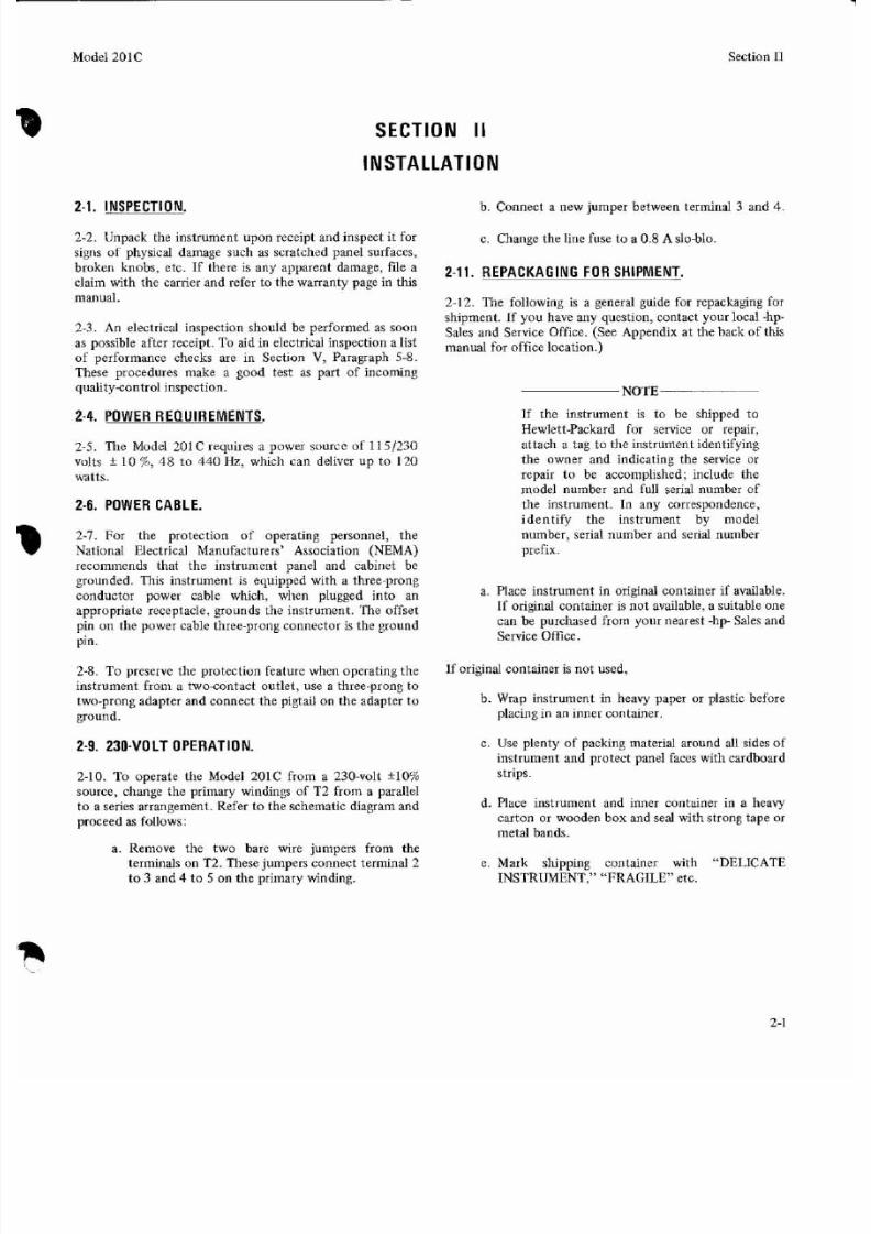
2-1. I N S P E C T I O N .
2-2. Unpack the instrument u pon receipt and inspect it forsigns of physical damage su ch as scratc hed panel surfaccs,
b. Connect a new jumper between terminal 3 and 4.
c. Change the line fuse to a 0.8 A slo-blo.
broken knobs, etc. If there is any apparent damage, fde aclaim with the carrier and refer to the warranty page in this
2-11. R E P A C K A G I N G F O R SHIPMENT,
manual.
2-3. An electrical inspection should be performcd as soonas possible after rece ipt. To aid in electrical inspection a listof performance checks are in Section V, Paragraph 5-8.
These procedures make a good test as part of incoming
qua lityco ntrol inspection. NOTE
2-12. The following is a general guide for repackaging forshipment. If you have any question, contact your local -hp-Sales and office.see ppendlx at the back of th i s
manual for office location,)
2-4. P O W E R R E Q U I R E M E N T S .
2-8 . The Model 201 C requires a power source of 118/230volts + 1 0 76 48 t o 440 Hz, which can deliver up to 120
waits.
2-6. P O W E R C A B L E .
2-1. For the protection of operating personnel, theNational Electrical Manufacturers’ Association (NEMA)recommends that the instrument panel and cabinet begrounded. This instrument is equipped with a three-prong
conductor power cablc which, when plugged into anappropriate receptacle, grounds the instrument. The offset
pin on the power cable three-prong connector is the groundpin.
2-8. To preserve the protection feature when operating theinstrument from a tw ocon tact out let , use a three-prong to
two-prong adapter an d connect th e pigtail on the adapter toground.
2-9. 2 3 0 - V O L T O P E R A T I O N .
2-10. To operate the Model 201C from a 230-volt * I O
source, change the primary windings of T2 f rom a parallelto a series arrangement. Refer to the schematic diagram and
proceed as follows:
a. Remove the two bare wire jumpen from theterminals on T2. These jum pers con nect terminal 2to 3 and 4 to 5 on th e prim ary winding.
If the instrument is to be shipped toHewlettPackard for service or repair,attach a tag to the instrument identifying
the owner and indicating the service orrepair t o be accomplished; include themodel number and full serial number ofthe instrument. In any correspondence,ident i fy the inst rument by modelnumber, serial number and serial number
prefix.
a. Place instrum ent in original container if available.If original container is not available, a suitable onc
can be purchased from your nearest h p - Sales andService Office.
If original container is not used,
b. Wrap instrument in heavy paper or plastic beforeplacing in an inner container.
c. Use plenty of packing material around all sides of
instrument and protect panel faces with cardboard
strips.
d. Place instrum ent and inner container in a heavy
carton or wooden box and seal with strong tape or
metal bands.
e. Mark shipping container with “DELICATEINSTRUMENT,” “FRAGILE etc.
2-1

7/27/2019 HP 201C Manual
http://slidepdf.com/reader/full/hp-201c-manual 9/27
Model 201C
SECTION
Section 111
OPERATING INSTRUCTIONS
3-1. C O N T R O L S A N D T E R M I N A L S .
3-2. ON. Toggle switch controls line voltage to instrum ent.
b. Turn th e power switch ON and allow approxima telyfive minutes for the instrument to reach its normaloperating temperature.
3-3. RANG E. Three-position rota ry switch selects variousvalues of resistance in the bridge circuit of the RC
oscillator. The position of this switch indicates themultiplying factor for the frequency dial calibration.
3 4 . FREQUENCY dial . This contro l varies the ca pacitancein the bridge circuit of the RC oscillator to vary ou tpu tfrequency between range switch steps. The dial is calibrated
f ro m 2 0 t o 200 and its indication multiplied by the factorindicated by the RANGE switch will give the actual output
frequency of the oscillator. The small knob below thefrequency dial is a vernier contro l for th c dial.
3-5.ATTENUATION. This is a dual concentric control.The inner cont rol is a potentiometer which adjusts theamplitude of the oscillator voltage admitted to the
amplifier, and therefore, it adjusts the output voltage of theinstrument fro m zero to a maximum value established bythe attenuator. The outer control is a bridged-T typeattenuator providing 0 to 40 dB of attenuation in 10 dBsteps.
3-6. OUTPUT terminal. Two binding posts on the lowercenter of the front panel are the output terminals for the
oscillator. Terminal m arked G is connected to the chassis ofthe instrument.
c. Set the FREQUENCY dial and RANGE switch fordesired outpu t frequency.
d. Set ATTENUATION outer control to 0 dB, then setinner control (amplitude) for desired output
voltage.
e. Set ATTENUATION outer contro l, if desired, toreduce o utp ut level in 10 dB steps.
NOTE
When the attenuator is in the O d B
position th e amplifier out put is delivered
from less than 600 ohms at frequencies
below 5000Hz , and it will produce its
rated output (3 watts) across a load of
600 ohms. When the attenuator is
positioned for 20 dB or more
attenuation, the internal impedance is
600 ohms.
3-8. L O W L E V E L A P P L IC A T I O N S .
3-9. To avoid excessive noise and hum at low outp ut levels
( 4 0 dBm or less), it it good practice to attenuate theoscillator output -30 or 4 0 dB and use the amplitude
control as an output vernier to obtain desired level.
3-7. O P E R A T I N G I N S T R U C T IO N S .
a. Connect the power cable to required power source.
3-1

7/27/2019 HP 201C Manual
http://slidepdf.com/reader/full/hp-201c-manual 10/27
Section IV Model 201C
OSCILLATOR AMPLIFIER 0-40db
ATTENUATORI 8. v2 v3, v4, v5
ATTENUATOR
6 n l O d b
6 n 2 0 - 4 0 d b
TTENU TION Q ATTENUATION]
VERNIER I
I
I
OWERSUPPLY
I
tOWER
SUPPLY
2 0 1 C 8 1988
Figure 4-1. Block Diagram of Model 201C

7/27/2019 HP 201C Manual
http://slidepdf.com/reader/full/hp-201c-manual 11/27
Model 201C Section IV
SECTION IV
THEORY O F
4-1. G E N E R A L .
4-2. The M odel 201C consists of an oscillator section, anamplifier section, an output attenuator and a power supplyas show n in the block d iag am , Figure 4.1.
4-3.O S C I L L A T O R S E C T I O N .
44 . The oscillator section consists of V1 and V2 as aresistance coup led amplifier contain ing tw o feedback loops.
The positive feedback loop sets up oscillation while thenegative feedback loop reduces distortion and maintains aconstant amplitude of oscillation. The positive feedbacknetwork contains fixed resistances (established by the
RANGE switch) and a variable capacitance. A simplifiedschematic diagam is shown in Figure 4-2. The network is
d es ig ne ds oth at R l , C l A a n d B = R 8 , C l C a n d D .
I I T I I
Figure 4-2. Simplified Sch ema tic Diagram of
Oscillator Section
4-5. The oscillator output is coupled to the input stage
through C8, and the input voltage is derived from thissignal. Oscillation will occur when there is zero phase shiftbetween the voltage applied to the netw ork a nd the voltageapplied to the grid of V1. The zero phase shift point is alsothe point of minimum loss through the network as shownin Figure 4-3. The frequency of oscillation (relative
frequ ency in F igure 4-3) is given by the expression:1
Fr = 2 n d (R1 .ClA,B) (R8. lC,D)
OPERATION
BO0 4
FREQUENCY
Figure 4 3. Oscillator Network Characteristics
4-6. The cathode by-pass capacitors in the oscillatorsection C5, C7 co rrect phase shift a t higher frequencies.
4-7. The negative feedback network minimizes change of
output amplitude with change in frequency. The
incandescent lamp, used as a cathode bias resistor for V1, is
part of the negative feedback voltage divider. It has a
temp eratu re resistance characteristic such tha t its resistance
increases in direct proportion to th e voltage applied to it .
Thus, changes in its resistance will change the amount of
negative feedback in the oscillator output. The thermal
inertia of the la mp is great enough to be unaffected by sine
wave voltages at th e lowe st frequencies involved.
4-8. M P L I F I E R S E C T IO N .
4-9. The amplifier section of the instrum ent consists of a
voltage amplifier V3A direct coupled to a phase inverter
V3B, and a push-pull output stage V4 and VS. The output
transformer contains a tertiary winding for overall negative
feedback around the amplifier. As a result of negative
feedback in excess of 30 dB, very little distortion is
introduce d by the amplifier section of the instrument.
4-1

7/27/2019 HP 201C Manual
http://slidepdf.com/reader/full/hp-201c-manual 12/27
Section V
TUBE
Table 5-1. Recommended Test Equipment
TYPE FUNCTION CHECK REQUIR ED
Model 201C
V6
Instrument Typ e
Multi-FunctionMeter
5AR 4 Rectifier Table 5 - 5 step 1
DistortionAnalyzer
Electronic
Counter
Required Characteristics
DC Voltage Range: 1 to 310 voltsOhmmeter Range: 1 ohm to 500 megohmsAccuracy: 53
AC Voltage Ranee: 1 m v to 100 volts
Distortion MeasurementRange: 20 Hz o 20 kHz
Frequency CalibrationAccuracy : +2
Elimination Characteristics:
Fundamental frequency reduced bymore than 60 dB
Sensitivity: Ability to measure distortionlevels of 1 full scale
Model
-hp- Model 421A
-hp- Model 33 1A
Frequency Range: 20 Hz to 20 kHz - h p Model 5223L
scillator Table 5-5, step 2Oscillator
6S NlG T Voltage Amp. Table 5 - 5 , step 3
phase inverter
6V6GT Output Tubc Table 5-5 step 3
6V6GT Output Tube

7/27/2019 HP 201C Manual
http://slidepdf.com/reader/full/hp-201c-manual 13/27
Model 201C
x 1
X I 0
X I 0 0
Section V
20so
20020so
20020SO
200
period: 49.5 to 50.5 msperiod: 1 9.9 to 20.1 ins
period: 4.95 to 5.05 ms
period: 4.95 to 5.05 ins
freq: 495 to 505 M z
freq: 19 80 to 2020 Hr
freq: 1980 to 2020 Hr
freq: 4950 to 5050 Hr
frcq: 19800 to 20200 Hz
SECTION V
MAINTENANCE
5-1. I N T R O D U C T I O N .
5-2. This section provides maintenance and serviceinformation for the Model 201C Audio Oscillator. Thesection includes recommended test equipment, a tube
replacement table, perform ance checks, adjustmen ts, repairprocedures and a troubleshooting table. The performance
checks will verify proper iiistrumen t ope ration.
5-3. T E S T E Q U I P M E N T .
5 4 . Test equipment recommended for use in maintainingand checking performance of the Model 201C is listed in
Table 5-1. Equipment having similar characteristics can besubstituted for the equipment listed.
5 -5 . P E R I O D I C M A I N T E N A N C E .
5 4 . The tuning capacitor drive bearing should belubricated once or twice a year depending upon the a mountof use. One drop of light machine oil in each of the bearingholes is adequate. The holes are located in the hearingprojections of the vertical casting behind the fro nt pane l.
5 1 . The inside of the instrument should be cleanedoccasionally to prevent accumulation of dust and dirt from
shorting plates of the main tuning capacitor.
Clean tuning capacitor with extreme care.DO NOT apply any force to i t whichcould beud the plates and destroycalibration. Compressed air under apressure no t to exceed 60 psi isrecom mend ed for cleaning.
5-8. P E R F O R M A N C E C H E C K S .
5-9. The Performance Checks are front panel proceduresdesigned to compare the Model 201C with its publishedspecifications. These checks may be incorporated inperiodic maintenance, post repair, and incoming inspection.The Performance Checks should be conducted before anyattempt is made to adjust or calibrate the instrument. APerformance Check Test Card is provided at th e end of thssection for recording the performance of the instrument.The card may be removed from the manual and used as apermanent record of the incoming inspection or of aroutine Performance C heck.
5-10. C A L I B R A T I O N A C C U R A C Y C H E CK .
a. Connect test setup as shown in Figure 5-1
b. Check the period or frequency for each frequency
setting shown in Table 5-3.
h p ZOIC
A U D I OO S C I L L A T O R
Figure 5-1. Calibration Accuracy Check
Table 5-3. Calibration Accuracy Check
5-11. F R E Q U E N C Y R E S P O N S E C H E C K .
a. Conne ct test setup as shown in Figure 5-2,
including a 600 ohm load resistor across theoutput terminals of the Model 201C.
b. Set the Model 201C frequency to 1 kHz andAttenuation Switch to 0 dB.
c. Adjust the M odel 201C amplitude vernier t oobtain 0 dB reading on the voltmeter.
d. Set th e M odel 201C to each of the frequencysettings in Table S 4 . At each setting the voltmetershould read 0 dB i-1 dB.
5-1

7/27/2019 HP 201C Manual
http://slidepdf.com/reader/full/hp-201c-manual 14/27
Section V Model 201C
h p ZOIC
AUDIO
OSCILLATOR
V O L T M E T E R
Figure 5-2. Freq uenc y Response and Outp ut Check
Table 5 4 . Frequency Response Check
Range Dial Setting Tolcrance
x1
x 1
XlOO
2 0
20020
200
20200
~~
-1 dB to + I dB
-1 dB to +I dB-1 d B t o + I dB-1 dB to +I dB
-1 dB to + I dB-1 d B t o + I d B
5-12. O U T P U T C H E C K .
a. Connect test setup as shown in Figure 5-2, using a600 ohm 3 watt load resistor.
b. Set the Model 201C Attenuation switch to 0 dB.
c. Increase attenuation vernier in CW direction untilthe voltmeter reads 42.5 volts. This is an outpu t of3 watts.
5-13. O l S T O R T l O N C H E C K .
5-14. O n e - W a tt O u t p u t .
a. Connect test setup as shown in Figure 5-3,including a 6 0 0 4 h m load resistor across theoutput terminals of Model 201C.
hp201C
AUDIOOSCILLATOR
Figure 5-3. Distortion Check
5-2
b. Set Model 331 A controls as follows:
INPUT . . . . . . . . . . . . . . . . . . . . . . . A FFREQUENCYRANGE . . . . . . . . . . . . . . X1
FREQUENCY dial . . . . . . . . . . . . . . . 50
FUNCTION . . . . . . . . . . . . . VOLTMETERMETER RANGE . . . . . . . . 3 0 RMS VOLTS
c. On Model 201C set RANGE t o X1 and frequenvydial to 50 (SO Hz).
d. Adjust output voltage levcl of Model 201C, withvernier, to obtain 24.5 volts on Model 331A.
e. On Model 331A set FUNCTION to SET LEVEL,
METER RANGE to loo , and adjust INPUTSENS ITIVITY for 100 (full scale is 100 ).
f . Set FUNCTION to DISTORTION and tu ne Model331A for null.
g. Set METER RANGE to 1 and retune for null.Reading shou ld be less tha n 1/2 (full scalc is 1 ).
h. Repeat steps a through g, except set Model 201CRANGE to XlOO and frequency dial to 200(20 kHz) and Model 331A FREQUE,NCY RANGEto XI K and FREQUENCY dial to 20.
5-15 . T h re e -Wa t t Ou tp u t .
a. Connect test setup as shown in Figure 5-3,including a 600 o h m 3 wa tt load resistor across theoutput terminals of Model 201C.
b. Set Model 33 1A contr ols as follows:
INPUT . . . . . . . . . . . . . . . . . . . . . . . A F
FREQUENCY RANGE . . . . . . . . . . . . . .XI
FREOUENCYdial . . . . . . . . . . . . . . . . 20~
FUNCTION . . . . . . . . . . . . . . . . . ME T E RMETER RANGE . . . . . . . . 100 RMS VOLTS
c . Model 201C set RANGE to X1 and frequencydial to 20 (20 Hz).
d. Adjust ou tput voltage level of Model 201C, w t hvernier , to obtain42.5 vol ts onModel331A.
e. On Model 331A set FUNCTION to SET LEVEL,METER RANGE to loo , and adjust INPUTSENSITIV ITY for 100 full scale is 100 ).
f. Set FUNCTION to DISTORTION and tune Model
331A for null.
g. Set METER RANGE to 1 and retune for null.Reading shou ld be less than 1 (full scale is 1 ).
h. Repeat steps a through g, except set Model 201CRANGE to XlOO and frequency dial to 200

7/27/2019 HP 201C Manual
http://slidepdf.com/reader/full/hp-201c-manual 15/27
Model 201C Section V
(20 kHz) and Model 331A FREQUENCY RANGEt o X1K and FREQUENCY dial to 20.
NOTE
If the Model 201C iy slightly out of
specification, refer to “Adjustments”
Paragaph 5-16 and “Factory SelectedComponents” Table 5 6 . If a malfunctionexists refer to “Troubleshooting” Para-graph 5-24.
5 - 1 6 . A D J U S T M E N T S .
5-17. P O W E R S U P P L Y .
5-18. Proper operation of the power supply is vital to
proper operation of the instrument. Excessive ripple in theoutp ut or a low o utpu t voltage can cause the instrument tohave excessive distortion or otherwise operate out of
specification. To check the power supply , measure thepower supply ripple and check the Bt voltage as describedin Table 5-5 (1). For cabinet removal refer to Paragraph
5-33.
5 -1 9 , O U T P U T V O L T A G E .
a. Connect Model 201C as shown in Figure 5-2 andproceed as follows:
b. Rotate RANGE switch to X I 0 position
c. Rotate frequency dial to 20.
d. Rotate amplitude control to 10 0 (fully clockwise).
e. Se t ATTENUATION switch to 0 dB position.
f. Adjust RlO for 4 5 volt indication on the volt-meter.
5 -2 0. D I S T O R T I O N A D J U S T M E N T .
a. Connect the 201C output to t he input of the331A D istortion Analyzer as in Figure 5-3.
b. Set the 201C frequency dial to 50 and th e Range
t o x1
c. Set the attenuation controls for a 42.5 volt outputinto a 600 ohm load.
d. Adjust R48 for minimum distortion as indicatedby the331A.
5 -2 1. F R E Q U E N C Y C A L I B R A T I O N .
a. Turn on the oscillator and allow 30 minutes for itto warm up. Put 600 ohm resistive load onoscillator fo r all adjustments.
b. Set the RANGE switch to X I 0 and the dial to 20 .Connect the instrument to the FrequencyCounter.
c. If the ou tput from the Model 201C is not 20 0 Hzadjust R7A so that the output is exactly 200 Hzwhen the d ial rests on 20 (X10 ange).
NOTE
It is necessary to remove the instrumentfrom the cabinet for each adjustment,and then replace it for check after eachadjustment. The instrument oscillates at adifferent frequency whcn removed fromthe cabinet. Use non-metallic (bakelite,etc.) aligning tools to adjust trimmercapacitors
d. Set the Model 201C outp ut to any convenientlevel for reference. Change the dial setting to 200
and note the output. The level should remain atthe established reference, and freque ncy should bewithin 1-112 percent of 2000 Hz. If this is not the
case, adjust CZ and C4 alternately to obtain2000 Hz at the established reference level.
e. Check dial tracking across the XI0 range. In nearlyall cases the dial tracking should be satisfactory. If,however, th e dial is ou t of calibration in the same
direction across the band , the dial may be adjustedslightly relative to the tuning unit as follows:
1. Remove center knob o n frequency dial
2. Loosen four screws which secure dial plate todrive sha ft.
3 . Reset dial by desired amount.
4. Tighten four securing screws. Replace centerknob.
5 . Rep eat steps b through d of Paragraph 5-21.
f. If the dial tracking cannot be brought into
specifications in this manner, or by compromisingthe calibration at the band extremes slightly(within specifications) to accommodate a larger
error in the middle of the band, then a retrackingof the dial and the main tuning capacitor isindicated. Retracking t he dial involves bending thesplit rotor plates on the main tuning capacitor C1.Assuming dial retracking is unnecessary, proceedwith steps g and h.
g. Place RANGE switch in the XI00 position, andturn the frequency dial to 20. Adjust R6A so thatthe instrument oscil lates at 2 k k .
5-3

7/27/2019 HP 201C Manual
http://slidepdf.com/reader/full/hp-201c-manual 16/27
Section V Model 201C
h. Place RANGE switch in the X1 position, and setthe frequency dial to 20. Adjust R8A so thatinstrument oscillates at 20 Hz
5 -2 2. D I A L R E T R A C K I N G .
5-23. Dial tracking is performed on th e X10 range
a. Check frequencies at 200, 150, 100, 70, 50, 30,and 20 on the dial.
b. For each point outside specifications, bend splitrotor plates (these plates are the outside plates of
each section of C1) as described below to bringpoint o n dial int o calibration.
NOTE
Outside rotor plates of each section aredivided into segments. The segmentassociated with specific dial points arethose which engage the stator when thedesired dial point is uqder the index. To
raise. the frequency spread the plates. Tolower frequency squeeze plates.
c. Sta rt bending a t highest frequency out o f
cal ibrat ion, and work toward the lowestfrequency. Bend the plates of the front twosections by the same amount as the rear twosections. It should not be necessary to bend platesnear the high end of the dial.
d. If the above procedures do not result in correctcalibration, start over by adjusting C2 and C4.Then work toward th e low e nd by setting the dialto the next numbered point and bending one ofthe outer rotor plates in each section 3f C1 at thepoint of mesh. C ontinue this procedure t o the low
end of the dial to obtain approximately corrtctfrequencies. Repeat the bending procedure fromthe high end, this time making fine adjustments offrequency with the other outer rotor plates. In thisway, bending of any one plate is minimized.
e. If bending process moves the dial out ofcalibration at ‘?A”, restore calibration at this
point by bending the plates rather than by anadjustment of R7A.
NOTE
If the X I 0 range is within specifications,and the high end of the X1 or XI 00 rangeis out of specifications, refer t o “Factory
Selected Com pone nts”, Table 5-6.
5 - 2 4 . T R O U B L E S H O O T I N G .
5 -2 5. T R O U B L E L O C A L I Z A T I O N .
5-26. If the instrument fails to operate, check the powersource, power cord, and fuse before attempting more
5-4
complicated troubleshooting. If the instrument operates,but not satisfactorily, check the test se tup for correctvoltages, connections, terminations, etc.
5-27. The conservative design of the Model 201C indicatesthat most normal aging effects will be remedied by tube
replacement and subsequent adjustments. Electrical
troubleshooting should always be preceded by a visualinspection. A cold tube found simply by touch may save
considerable time an d effort in restoring t he instrum ent to
operation. Look for signs of damage and overheated or
burned-out components associated with certain types oftub e failure; be alert for looseness of parts wh ich, if no ttrouble sources themselves, suggest areas of future trouble.
The Troubleshooting Cha rt, Table 5-5, lists checks to beperformed starting with the power supply and proceedingthrough the instrument in a manner which isolates circuit
failures and also includes possible causes and remedies.Isolation of a circuit failure is often possible by simplyoperating the front pane1 controls and observing their
effect.
5 -2 8. T R O U B L E S H O O T I N G C H A R T .
5-29 . For simplification in the following c hart , tubesusually have been referenced, but remember thatcomponents associated with reference tubes are also failurepossibilities. Perform the steps in the chart in the ordergiven since the chart assumes that the section ahead of theone under investigation is operating satisfactorily. For alltesting of the M odel 201C the use of a variable transformer
to adjust the line voltage to +lo of the norm al line voltageis recommended. An instrument in good condition should
opera te over this range. An instr um ent with marginal
operation (from weak tubes, etc.) can be quickly identifiedat low line voltages, and such weaknesses become easier totrace.
5 -3 0. E X C E S S I V E O I S T O R T I O N .
5-31. In general, distortion in the Model 201C can come
from the following:
a. Leaky coupling capacitors, C6, C8 , C9, C 10, C11.There should be no dc voltage on grids following
these c apacitors.
b. Defective electrolytic fdter and decoupling capa-
citors. Make ripple measurements as described inTable 5-5 .
c. Defective tubes. When a tube is replaced in theinstrument, the distortion measurement should berechecked.
d. Low B+. Check the supply voltages against those
shown in the Voltage and Resistance diagram witha line voltage of 115 volts.
5 - 3 2 . R E P A I R .

7/27/2019 HP 201C Manual
http://slidepdf.com/reader/full/hp-201c-manual 17/27
Model 201C Section V
Table 5-5 . Troubleshootinr C hart
CHECK O R SYMPTOM
1 . POWER SUPPLY
Measure +31 0 VDC (at 115 Vline) between pin 8,
V6 and chassis.
Voltage low
Measure power supply ripple at pin 4 of V4 or VS.
Ripple in excess of .25 vac.
Measure ripple at junction R2 8 and C12A.
Ripple in excess of 0.01 vac.
2. OSCILLATOR
Measure oscillator hum between negative terminalof C8 and chassis. Remove lamp RT11 to eliminateoscillator signal.
Hum in excess of 0.02 vac
Replace lamp and measure oscillator voltage be-tween negative terminal of C8 a nd chassis (seeFigure 5-5 .
Oscillator voltage no t within range indica ted onschematic.
Excessively high OSC voltage
Measure distortion between negative terminal ofC 8 an d chassis.
If it exceeds .5 at 1 watt an d 1000Hz
POSSIBLE CAUSE
Defective V6
Defective fdtercapacitor C12B or C
Defective V6
Defective C12A
Defective V1 or V2
Defect ive lamp R T ll
R10 o ut of adjustment.Defective V1 or V2.
Dirty contacts onRANGE switch
Shorted C1 , C2, C3,o r c4 .
Defective lamp RTll(Notch will appearin oscillator outputwaveform viewed onoscilloscope .)
Defective VI or V2Defective lamp, RTll
REMEDY
Replace
Replace
Replace
Replace
Replace.
Replace l amp5-37).
(See Paragraph
Adjust R10 for properoscillator voltage orreplace V1 or V2.
Check and clean RANGEswitch. Replace assemblywhen resistors are openor damaged. See Para-graph 5-39.
Replace defective trim.mers (C2, C 3, or C4).Foreign material mayshort C1.
Replace lamp (See Paragraph5-37).
Replace (See Paragraph 5-35).Replace lamp.
5-5

7/27/2019 HP 201C Manual
http://slidepdf.com/reader/full/hp-201c-manual 18/27
Section V
Table 5-5. Troubleshoo ting Chart (Cont’d)
Model 201C
CHECK OR SYMPTOM
3. AMPLIFIER
Load instrument with 600 ohms. M easure lowfrequency distortion at output terminals.
Excessive 2nd Harmonic distortion.
Load instrument with 600 ohms. Measure signalvoltage o n V3A grid (pin 5) for approximately13 V rms when instrumen t delivers 1 watt. Signalvoltage on grids (pin 5) of V4 a nd V5 should beapproximately 5 V rms.
Weak signals driving V4 and V 5
Amplitudes of signals driving V4 and V5not equal.
Rotation of amplitude control causes erratic
amplitude variation in output.
Measure dc voltage for approximately 0.2 volts.Voltage high.
Voltage above sa tisfactory. Contro l still pro-duces unstable o utp ut variation.
POSSIBLE CAUSE
Defective V4 or VS
Defective V3
Defective R21or R22
Defective C9
Defective R17
REMEDY
Replace
Replace
Investigate an d replace
Replace (See Paragraph 5-31).
Replace
v4 v3 v5 V 6 c12
5 2
R25
C l l
s; R i 7 d9 T I T 2
Figure 5 4 . Left Side View

7/27/2019 HP 201C Manual
http://slidepdf.com/reader/full/hp-201c-manual 19/27
Model 201C Section V
R I O R26 C 5 C 6 R13 R14 C 7 SI
R 3 3 R 2 3 R Z I R Z 9
C I D 54
\ I
Figure 5 5. Bottom and Right Side Views

7/27/2019 HP 201C Manual
http://slidepdf.com/reader/full/hp-201c-manual 20/27
Section V Model 201C
5-33. C A B I N E T R E M O V A L .
5-34. To remove instrum ent from the cabinet, unscrew thetwo machine screws on the rear of cabinet and pull frontpanel forward. The bezel remains attached to front panel.
5-35. T U B E R E P L A C E M E N T .
5-36. Tubes used in t h e Model 201C are listed in the Tub e
Replacement List (Table 5-2). A tube m ay be replaced with
any tube of its type having standard characteristics, butdistortion measurements should be made after replacing
any tube, with the exception of the rectifier tube , to insurethat the instrument still meets the specifications set forth in
the front of this manual.
5-37. R E P L A C E M E N T O F L A M P , RTl1.
5-38. The lamp operates well below its rating and should
have a long life, unless it is damaged by severe mechanicalvibration. A damaged lamp may be detected by thepresence of a notch in t h e output waveform, and by thepresence of excessive oscillator voltage. If the lamp opens,the circuit will not oscillate. When the lamp is replaced,check the oscillator voltage between the negative terminalof C 8 and th e chassis. If th e voltage does not fall within the
COMPONENT
C5*
C13* and R30*
C14*
C15*
C17*
RY *
R14*
R20*
limits specified on the schematic, adjust R10 to obtainproper oscillator voltage.
5-39. R E P L A C I N G R A N G E S W I TC H .
a. Remove instrument case (see Paragraph 5-33)
b. Remove defective RANG E switch. Note routing ofleads.
c. Install replacement switch with black wire towardthe center shield of the chassis and the wiper lugson the ceramic wafer horizontal.
d. Carry out frequency calibration procedure as
described in Paragraph 5-21.
5-40 . A D J U S T M E N T O F F A C T O R Y S EL E CT ED
C O M P O N E N T S .
541. Certain components within the Model 201C areindividually selected in order to compensate for slightlyvarying circuit parameters. These components are denotedby an asterisk (*) on the schem atic, and th e typical value is
shown. Table 6 describes the function of the factoryselected components and gives instructions for theirselection. Normally, these components do not need to be
changed unless another associated component is changed.
Table 5 4 . Factory Selected Com ponents
FUNCTION AND SELECTION
Compensates for High Fre quen cy responseDecrease C to increase amplitu de (X100 range).
Minimizes distortion a t 20 kHzChange size of R 30 first. C13 has very littleeffec t. Value of R30 is functio n ofoscillator tube s.
Adjusts frequency at high end of X I0 range.
Adjusts frequency a t high end of X1 range.
Decreases distortion caused by oscillationsin the output amplifier.
Provides proper range for R10 Output Voltage
Adju stme nt. Increase RY t o increase amp litude.
Adjusts bias level of V2.
Changes loop gain of amplifier.
MIN.
2 7 p F
10 kohm
0
0
1800 ohms
AVERAGE
5 6 p F
5 6 0 p F
1 2 k o hm
0
1 PF
4 7 p F
2200 ohms
680 ohms
270 kohms
MAX.
6 8 p F
16 kohm
1.5 pF
50 p F
2600 ohms
5-8

7/27/2019 HP 201C Manual
http://slidepdf.com/reader/full/hp-201c-manual 21/27
V 65 A R 4
v 5
6V6
v 3
6 S N 7
V 46V6
470K
15 18
85 14
OTES
1. CONDITIONS OF MEASUREMENT
A L L V O L T A G E S A N D
RESISTANCES MEASURED FROMPOINTS SHOWN TU CHASSISW I T H 122 M E GOHM INP UT
IMPEDANCE VTVM.
LINEVOLTACE: 115VI60 H z
2. CONTROL SETTINGS
FREQ. DIAL . . . . . . . . . . . . . . ,100
RANGE . . . . . . . . . . . . . . . . . . XI0AMPLITUDE . . . . . . . . . . . . .MAX.
r--E
5 15K
V I
14 68
V 26 A Q 5
Figure 5 6. Tube Location, Voltage and Resistance

7/27/2019 HP 201C Manual
http://slidepdf.com/reader/full/hp-201c-manual 22/27
3 * v n i w SELLCII'LI DURiNC
MANUIACTLRE
PANEL CONTKOL
5 . PAUEJ. MAKKTNC
*
RI O
R 3 A
R 38 3 K A M P L I T U D E
F R EQIX100/ R E S P O N S E
F R E Q U E N C Y
D I A L
7
8
COPYRIGHT 1955 B Y H E W L E T T -PACKARD COMPANY

7/27/2019 HP 201C Manual
http://slidepdf.com/reader/full/hp-201c-manual 23/27
R425 6 K
CI O01
R 2 3z 2 0 v R30
2 4 7 0 K9
0.047 C13
-.
M t5 v36 S N 7 G T
C I I
R 2 84700
T T
4
R I2
VERNIER
15K
c12c
128

7/27/2019 HP 201C Manual
http://slidepdf.com/reader/full/hp-201c-manual 24/27
Model 201C Section V
R 3 4 R 3 5 R 3 6 R 3 759480 18370 5400 1297
I
S 3 A
ATTENUATION
325v
CI5V
4
t325V
t 350V
5 A R 4 G T
C 1 2 C l
R 2 9
v2 v3 V S DSI
3 7 2 2
Figure 5-7. S chem atic DiagramPage 5-9/5-10

7/27/2019 HP 201C Manual
http://slidepdf.com/reader/full/hp-201c-manual 25/27
Appendix C
351 061 08 and below
Model 201C
10, 11, 12 , 1 3
M A N U A L B A C K D A T I N G C H A N G E S
1258 through 13 58
MODEL 201C
AUDIO OSCILLATOR
Manual Serial Prefixed: 351--hp- pdrt NO. 201C-906
This manual backdating sheet makes this manual applicable to earlier instruments.Instrument-compouent values that differ from those in the manual, yet are notlisted in the backdating sh eet, should be replaced using the part num ber given in themanual.
4 t h r o u g h 9 , 1 1 , 1 2 , 1 3
Instrument Serial Number Make Manual Changes
557 and below 1 th rou gh9 ,11 , 12,13
351-06357 to 06 315 8
Instrument Serial Number Make Manual Changes
1 2 , 1 3
311- 8 through 13
308-
558 through 857 2 throu eh9 . 11. 12. 13
7 t hrou g h 9 , 1 1 , 12,13
331- 9 13
858 through 125 7 3 12. 13
6 t h r o u g h 9 , 1 1 , 1 2 , 1 3
CHANGENO.
CHANGE NO. 2
CHANGE NO. 3
CHANGE NO. 4
CHANGE NO. 5
Table of Replaceable Parts:Coupler, flexible: Change to -hp-P art No. 5060-0210.C12A is single capa citor, 1 0 uF; hp- Part No. 0 1 8 0 4 0 0 2 .Change C12B to C12A , B.
Table of Replaceable Parts and Figure 5-8, Sch ema tic:Dele te R 42 , 45 .
Change T1 to hp-P ar t No . 912 040 37 .If TI is replaced by current Part No., add R42 an d R45
Freq uenc y drive gears are chang ed; separate parts are available for rep lacem ent.
For entire gear assy replacement, use current gear assy, hp- Part No. 200AB-36BGear (32 pitch); 200AB-36C Gear (32 pitch); 2AC-100Y shaft with gear (32pitch).
Table of R eplaceable Parts:
Add C16*: 560 p F (factory adjusted), h p - Part No. 01 40 40 28 (average value).Add R16*: 6800 ohms (factory adjusted), -hp- Part No. 0690-6821 (average
Parallel combination R16 and C 16 is conne cted in series with signal lead t o top)
Delete R46.
value).
AMPLITUDE control R17.
Delete C17* (This capacitor m ay be add ed to improve distortion.)
Table of Replaceable Parts, Miscellaneous:Add the following:
Disc, vernier 50 20 42 36Disc, vernier drive 50 40 42 11Spring, compression 14 60 40 19

7/27/2019 HP 201C Manual
http://slidepdf.com/reader/full/hp-201c-manual 26/27
Model 201C Appendix C
Delete the following:Disc assy, vernier drive; -hp-Pa rt No. 50 40 46 07 ; Mfr. 2848O;TQ 1.Sor ine th rus t ; h o - Part No . 50004 637;M fr . 28480; TQ(It is advisable to replace with c urren t vernier drive assy.)
CHANGE NO. 6 Table of Rep laceable Parts:
S3: Attenuator switch assy, w/po t; change to 201C-19A;pot ody--hp-PartNo.21004115;
switch w/pot - hp-Part No. 31004124.
CHANGE NO. 7 Table of R eplaceable Parts: (see Figure 1
Add R46: 390 kohms, hp- Part No. 0687-3941.R9: Change to 2.4 kohms, h p - Part NO. 0689-2425.
R12 : Change to 8 2 kohms, -hp-Part No. 069043231.R14: Change to 1 kohm, -hp-Pa rt No. 0693-1021.R15: Change to 7.5 kohms, -hp-Par t No . 0816400 7 .V1: Change to 6 9 7 , -hp-Par t No . 1923 4037 .V2: Change to 6K6, hp -P ar t No. 1 9 2 3 4 0 3 3 .
22-26 VACAT 1000 CPS
T T
Figure 1
CHANGE NO. 8 Table of Replaceable Parts:
C12: Change to 4 section, 2 0 uF /sect, -hp- Part No. 0 1 8 0 4 0 2 5 .C12B: Change to 20 uF.R27 : Change to 33 kohms, -hp-Part No. 0693-3331.
NOTEStock No’s. in c urren t manual may be used to impro ve hum anddistortion.
Table of R eplaceable Parts:
No . 21004 385 .
CHANGE NO. 9Rotar y, sw itch, with pot: change to hp - Par t No . 3100437 1 ;po t on ly , -hp- Part
Knob: change to -hp- Part No. 037 04 02 4.
CHANGE NO. 10 For Serials Prefixed 311-, 331- an d3 51 46 10 8 a nd below only
Table of Replaceable Parts and Figure 5-8 Schematic:Delete R46

7/27/2019 HP 201C Manual
http://slidepdf.com/reader/full/hp-201c-manual 27/27
Appendix C Model 201C
CHANGE NO. 1 1 Table of Re placeable Parts and Figure 5 8 SchematicDelete: C13 and R30.
CHANGE NO. 12 Table of Replace able Parts and Figure 5-8 Schematic:Delete: R47, 169 ohm resistor -hp- Part No. 08 11 40 41 and R 48 potentiometer
1M) ohms hp-P ar t No. 210 04730 .Add: R24 Resistor, fxd cam p 470 ohms + O 2 W -hp- Part No. 0 6 9 3 4 7 1 1 an d
R45 Resistor fxd camp 1 kohm ?I O 2 W -hp- Part No. 0693.1021. Changeschem atic diagram as in Figure 2.
Figure 2
ATTENUATOR S3 Instrument Serial No. Switch with pot Pot alone
0 t o 2 3 6 4 3 2 0 7 3 1 0 0 4 1 2 4 2 1 0 0 4 1153 0 8 4 3 2 0 8 to 3 3 1 4 3 6 3 2 3 1 0 0 4 3 7 1 2 1 0 0 4 3 8 5
35143 633 and above 31004 788 21004 839
NOTEThe above switches and pots must be used together as designated
although the current attenuator assembly may be used on any serialnumbered instrument.
CHANGE NO. 13 Figure 5-7:Change primary power input to T2 as shown below:
Table 6-1:
Change-hp- part no. W1 to 8120-0050Change -hp- part no. of Shield: bottom (in miscellaneous) to 200 AB 4B .Change -hp- part no. of Bracket: pot (in miscellaneous) to 6189.129.
Delete J1 and S4.
CHANGE NO. 14 Table 6-1 :
Change the -hp- part no. of MPI t o 1 5 0 0 4 0 0 2 .