Embed Size (px)
Citation preview
HPS Oil & Gas Applications
By Mike Van Gheem

Locations
Hammond Power Solutions is North America’s largest and broadest manufacturer of dry-type transformers:
Warehouses are located in CA, FL, IL, NC, TX, WA, WI (USA) & BC, ON, QB (Canada)

Contact & Technical Information
Canada:Tel: 519-822-2441 / Fax: [email protected]
United States: Tel: 608-356-3921 / Fax: 608-355-7623)[email protected]

Product Scope
STANDARD PRODUCTS• Our catalogs offer thousands of standard transformers from 25VA to 5MVA.• Control Transformers
– Encapsulated Machine Tool Industrial– Industrial Open Core & Coil
• Buck-Boost Transformers• General Purpose Enclosed Transformers• Line Reactors and DV/DT Filters• Energy Efficient Distribution Transformers
– General Purpose– K-Factor– Harmonic Mitigating
• Drive Isolation Transformers (Energy Efficient Option)• Autotransformers• Encapsulated Transformers
– Commercial Encapsulated– Encapsulated Transformers for Hazardous Locations
• Medium Voltage Distribution (Power) Transformers (Energy Efficient Option)

Product Scope
CUSTOM PRODUCTSWe are one of the industry’s most technically capable manufacturer's producing the broadest and most competitive range of custom dry-type transformers and related magnetic products• We design to your specifications in days instead of weeks or months• Offer custom designs from 10VA - 34MVA and up to 46,000 volts• Offer custom air core and iron reactors up to 2500 amps• Custom Transformers include:
– Marine and Land Duty Transformers– Excitation Transformers– Rectifier Duty Transformers– Traction Duty Transformers– Mining Duty Excavator Transformers– Large Indoor/Outdoor Current Limiting Air-Core Reactors– 12, 18, and 24 Multi-Pulse Drive/Inverter Duty Transformers– Cast coil through HPS – Euroelettro is available for the European market– Cast coil and oil through HPS – PETE is available for the Asian market.

Product Scope
ENGINEERING• Over 3000 custom designs are engineered and built every year.• HPS has designed over 250,000 designs in over 90 years of business.• We have over 40 engineers and technicians designing exactly what you need.
MATERIALS & PROCESSES• A wide range selection of standard materials and processes are available,
which provide the most cost effective and rugged designs.• Windings are available in copper or aluminum.• High performance impregnation processes - VPI, Epoxy• BIL ranges from 10 kV to 200 kV• Enclosures for indoor, outdoor and harsh environments such as mining and
marine duty• Step lap mitered cores• Disk or barrel wound coils

Product Scope
QUALITY ASSURANCE• All facilities have implemented quality management systems based on ISO
9001:2008 and are ROHS and REACH compliant.• Our units are designed to meet ANSI, CSA, UL, IEC, ABS and NEMA
standards required by our customers.• With our commitment to 'Excellence' and 'Continuous Improvement', we
build value and reliability into every product.• HPS stands behind its quality with warranties on both standard and special
products.

Major concerns in Oil & Gas
Safety – Can a product improve the safety?
Survivability – Will the product survive longer?
Causes of Magnetics Failures
• Typically after 30-40 years of use.• High load factors, harmonics and ambient
temperature can further reduce transformer life.
Heat – Ultimately the heat produced by transformer
losses will cause insulation failure.
• 600V Class does not define a BIL level.Over Voltage – A spike
overwhelms the insulation system and creates a self-
sustaining arc.
• Moisture or dust reduces insulation values.A contaminant is introduced.
• Connections should be inspected.Improper or loose connections.

Market Components
Extraction
Land DrillingMarine DrillingTar Sands
Transportation
PumpingLiquefied Natural GasProcessing
Refineries
PetroleumNatural GasChemical Plants

Account Targets
Distributors
End Users
Specifying Engineers

Oil & Gas Application Concerns
Safety is very important in the Oil & Gas industry but it must be discussed carefully.
Make reference to products as “facilitating safety” in a broad sense. There are no absolutes when it comes to safety.
In a legal sense, referring to your product as “safe” or “used when safety is a priority” may create a misleading perception related to product performance.
It is best to refer to these products as providing “improved safety” or “enhanced safety” rather than “safe” or “safety” products.

End of Life / MTBF
Transformers failures are very expensive because of lost commercial time. • Repair time exceeds many temporary power devices such as UPS’s.• Long term backup power often runs through the transformer.
Typically a transformer will last +30 years. • High load factors, ambient temperatures and harmonics can reduce the life of
a transformer’s insulation components.
Signs of failure would include:• Discoloration (clear to yellow, yellow to brown) or cracking of the insulation. • Lower megger values could indicate insulation damage. • Excessive heat, harmonics, high voltage spikes (including megger tests),
conductive dust and moisture can significantly reduce the expected lifetime.

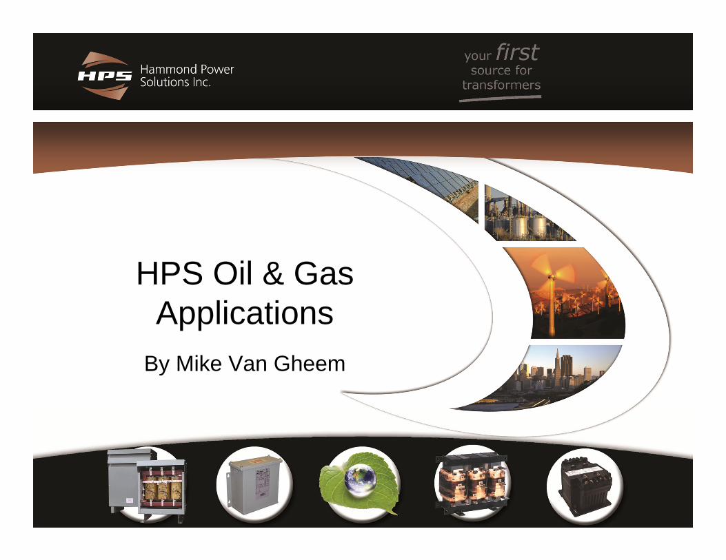
Causes of Magnetics Failures
Heat – Ultimately the heat produced by transformer losses will cause insulation failure.• Typically after 30-40 years of use.• High load factors, harmonics and ambient temperature can further reduce transformer life.
Over Voltage – A spike overwhelms the insulation system and creates a self-sustaining arc.• 600V Class does not define a BIL level.
A contaminant is introduced.• Moisture or dust reduces insulation values.
Improper or loose connections.• Connections should be inspected.

Preventative Maintenance
De-Energize transformer for testing.
Tighten the lugs every 6-12 months.• Mark lugs to show slippage.• Tighten per torque specs.
Check for dust on a transformer. • Blow off if needed.• Regard all dust as potentially conductive.
Thermal Scans are and effective method of checking for poor cooling, loose lugs, etc.

In-Rush Concerns
• Standard Efficiency Units: Inrush is 6 and 12 times the full load transformer current.
• High Efficiency Units: Inrush 8 and 14 times the full load transformer current.• Little Inrush change between TP1 and NEMA Premium.• Little Inrush change between standard and high efficiency
medium voltage units.
When a transformer is energized, it produces an inrush current to establish the electro-magnetic field.
Good circuit protection coordination dictates that the transformer’s overcurrent protection will not trip at the transformer’s energization while protecting it from damage.

In-Rush Concerns
• Secondary is sized at 125% of FLA.• Primary breaker at up to 250% FLA.
The National Electrical Code (NEC) requires primary and secondary protection.
When the transformer is energized, the primary breaker is the only overcurrent protective device through which the inrush current will pass, and therefore it is the only breaker required to coordinate with the transformer inrush.
In-Rush Concerns
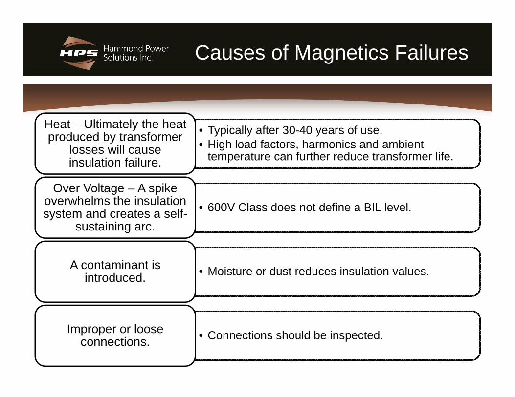
• Ideally, it’s the primary breaker, but either or both breakers could be for the protection of the transformer.
• The primary is ideal because it would protect from any fault that occurs between the secondary conductors and the primary breaker.
• Although it is ideal, accommodating the inrush and protecting the transformer with just the primary breaker can create a challenge.
Now, consider both fault and overload damage protection: Which breaker should protect the transformer?
• This occurs because the secondary coil’s closer proximity to the core results in higher inrush when it is energized first.
Back-feeding a transformer can significantly increase its inrush profile.
• The quicker the fault and the higher the deviation in phase angle at de- and re-energization the higher the current inrush.
Inrush is highly dependent on how long a transformer is de-energized and what was the voltage phase-angle was at de-energization and re-energization for short duration faults.

K-Rated is the New Normal
• It has changed the way we design, install and calculate losses for energy conservation
• High Efficiency units improves efficiency under Non-Linear Load Loss • Phase Shifting techniques reclaims more energy under non-linear
loads.
Non-linear loads which cause harmonics make up the majority of the
electrical loads.
• Harmonics cause the equivalent full load capacity to be reduced.• If less than half of the transformer’s load is non-linear, use K=4.• If more than half of the transformer’s load is non-linear use K=13• Use K=20 for critical loads with high harmonics.
Many projects specify general purpose transformers not
designed to operate non-linear loads.
• Single-phase sources produce the most current at the 3rd harmonic. • Three-phase sources (VFD’s, large DC Power supplies) produce the
most current at the 5th harmonic and don’t produce 3rd harmonics. • Higher order harmonics produce more heat per amp than lower order
harmonics.
Harmonics are typically odd (3rd, 5th,
7th, etc.).

Average World Temperatures

Cold Environments
De-Energized Storage:
• Frost and moisture can cause corrosion and short circuits.
• Frost and moisture can lower insulation ratings.
• Space heaters protect for corrosion and moisture.
Temperatures below freezing may
require:
• NEMA 3RE (E=Enhanced) enclosure protects for horizontal rain and snow.
• Mount in good areas to protect from drifting snow.
• Transformers are warm, rodent or insect guards may be needed.
Re-Energization:
• Follow dry-out procedures before energization.
• Transformers energized without proper start-up procedures can affect both the survivability of magnetics and the safety of workers.
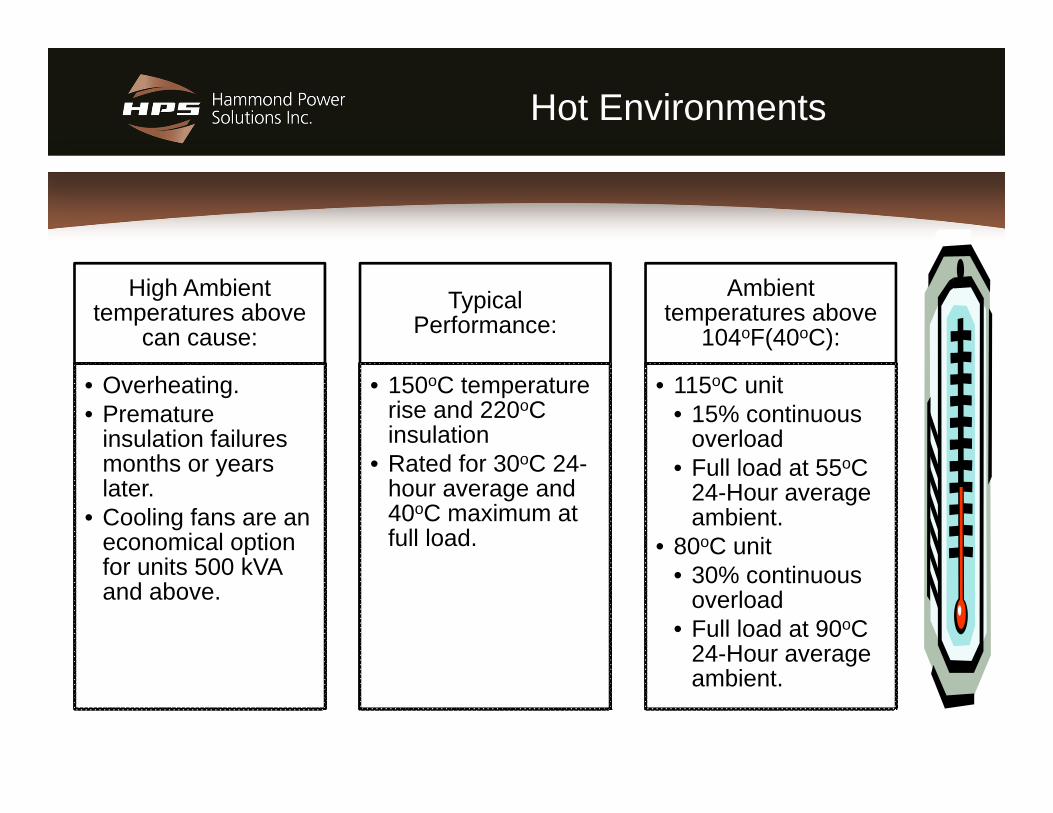
Hot Environments
High Ambient temperatures above
can cause:
• Overheating. • Premature
insulation failures months or years later.
• Cooling fans are an economical option for units 500 kVA and above.
Typical Performance:
• 150oC temperature rise and 220oC insulation
• Rated for 30oC 24-hour average and 40oC maximum at full load.
Ambient temperatures above
104oF(40oC):
• 115oC unit• 15% continuous
overload• Full load at 55oC
24-Hour average ambient.
• 80oC unit• 30% continuous
overload• Full load at 90oC
24-Hour average ambient.

Dust Concerns

Dust Concerns
• All dust should be considered conductive. • Arcing can occur through dust.• Dust can limit cooling capacity.
Dust:
• Up to 225 kVA in a potted design• Up to about 1500 kVA in a NEMA 4/12
enclosure
Non-VentilatedEnclosure:
• Difficult to use.• Maintained so dust build-up doesn’t impede
filter airflow. • Cannot be retro-fitted without de-rating.
Filters:
Transformers not designed for dusty environments can affect both the survivability of magnetics and the safety of workers.

Mechanical
Must be designed for the mechanical
shocks and vibrations to
provide survivability and
the safety of workers.
May need additional mechanical bracing if installed on moving equipment. • Skid Duty• Land Drilling Duty• Marine Duty
Large magnetics are moved via a spreader bar to the top of the core.• Larger units can
be ordered with a fork-lift capable base.
Mobile machinery can cause severe mechanical stresses, standard commercial transformers may not survive.• Specify for
Seismic Zone 4. • Some Applications
exceed Seismic Zone 4 specifications

Skid Mounted - Stresses & Environment
• Can be susceptible to leaks from cracked seals. • Need some method to contain the oil should a leak develop. • Air Tight
Oil Type
• Weigh less than oil immersed units.• Can be ordered with fork-lift provisions up to 2000 kVA instead
of the more traditional top lifting arrangements.
Dry Type
• Disconnected units may need heaters to reduce condensation.• May need louvers installed on openings if transported to limit
physical damage or moisture coming through the vent holes.• If not powered from the US or Canadian national power grid
may not need to meet mandated efficiency levels.
Transportation and Storage

Wind Speeds

Enclosure Options
Type 3R Enclosure
Most manufactures use field installed hood’s.
HPS distribution units come standard NEMA 3R.
NEMA 3R should be used in presence of fire sprinklers.
Degree of protection against
Falling dirt @ 45o
Falling rain @ 45o
Falling snow @ 45o
No protection for horizontally blowing dust, rain or snow.

NEMA 3R Enclosure Type
Design
Features
May use sloped roofs to avoid water and ice collection
Corrosion protection
Optional stainless steel hardware.
Bottoms of larger units are flush mounted to concrete slab.Horizontally blowing rain and snow can cause failures.
Can let in dust.

NEMA 3R Enclosure Type
Design features:• May use sloped roofs to avoid
water and ice collection• Corrosion protection• Optional stainless steel
hardware.• Bottoms of larger units are
flush mounted to concrete slab.• Horizontally blowing rain and
snow can cause failures.• Not dust tight.

NEMA 3RE Enhanced
Ventilated similar to NEMA Type 3R, as well as providing a degree of protection against:
Horizontally blowing Snow
Horizontally blowing
Rain
Nameplate marked as “NEMA 3R*”.
Nameplate shows* with Enhanced
features• More economical
to order 75 kVA and below as A NEMA 4/12 enclosure.

NEMA 3RE Enhanced
NEMA 3R Enhanced Design Features:
Filters to prevent the ingress of large dust, snow and rain.
Interior baffles to direct snow, rain and dust away from live parts

NEMA 4/12 Enclosure
General Specifications
Indoor or Outdoor use up to 1500 kVA.
Non-ventilated
Gasketted against dust, rain and snow.
Degree of protection against
Splashing or hose directed water
Snow, Sleet, and Dust
Not Submersible
Very rugged welded enclosure design for rough handling.
Higher in cost but…
Proven ability to survive stressful environments
Reduces costly failures.

NEMA 4X Enclosure
Same as NEMA
4/12, as well it
provides:
Corrosion Resistance
Must use stainless steel, fiberglass can’t handle heat magnetics produce.
304 SS for general purpose, 316 SS for marine or other caustic areas.
Design Features:
Corrosion resistant: Gasketed and dust-tight.
Very rugged welded enclosure design for rough handling.
Consider for areas combine wind and sand which can degrade paint.

PowerPlus Mini Power Center
HPS Shielded Transformer
Pad-Lockable Captive Hardware
Hinged Removable Cover
Primary Breaker(included)
Secondary Breaker(included)
Conduit Knockouts
Type 3R Enclosure or Stainless Steel
• Combines a pre-wired primary & secondary main breaker, secondary power panel, and a dry-type shielded transformer in a Type 3R enclosure.
• Saves time, money and space.• Lockable for security, safety and lock-out / tag-out programs.

Titan Potted Series
• All Copper Construction.• Encapsulated in epoxy for demanding environmental and
mechanical applications.• Unit cannot be submerged.
• ABS Marine Duty Rated as standard.• Class1, Div. II as standard.• Up to 37 kVA single phase and 225 kVA three phase.• Gasket kit upgrades 3-phase enclosures to NEMA 4/12.• Compact design compared to ventilated units.
Provides a rugged alternative to ventilated transformers for
difficult and critical applications:

Marine Duty

Marine Duty Comparison
Specification ABS DNV IEEE45 BV Lloyd’s
Voltage Variation + 6%-10%
+2.5%-2.5%
+5%-5% Not Stated + 6%
-10%Voltage Variation
Transient+20%-20%
+20%-15%
+16%-16% Not Stated +20%
-15%
Frequency Variation +5%-5%
+5%-5%
+3%-3% Not Stated +5%
-5%FrequencyVariationTransient
+10%-10%
+10%-10%
+4%-4% Not Stated +10%
-10%
THD - 5% 5% Not Stated 8%
Design Ambient Temperature
45 Deg C in Engine rooms and 40 Deg C at
other places.35 Deg C at controlled
locations
45 Deg C in all locations35 Deg C at controlled
locations
40 deg C to 65 Deg C at different locations 45 Deg C 45 Deg C
Temperature Rise150 Deg C
( For 40 Deg C ambient, for class H insulation)
140 Deg C( For 45 Deg C ambient,
for 220 Deg C class insulation)
130 Deg C(For 40 Deg C ambient for
class H insulation)
120 Deg C( Class H insulation)
110 Deg C(Class H insulation)
Enclosure
IP20-
IP56Depending on the
locations
IP20-
IP56Depending on the
locations
Drip proof as a minimum
IP20-
IP55Depending on locations
Not Stated
Prevention of Accumulation of
Moisture
Transformers above 10kVA provided with
heaters.Not Stated Not Stated Not Stated Not Stated
Winding Material Not indicated Not indicated Copper Not indicated Not Stated
Scope Includes Mobile Offshore Drilling
Includes Mobile Offshore Drilling
Excludes Mobile Offshore Drilling
Includes Mobile Offshore Drilling Not Stated
Approval Process Certification Witness Inspection Not Stated Witness Inspection Witness Inspection

Marine Duty Applications
• Horizontally blowing snow and wind use NEMA 3RE, NEMA 4/12 of NEMA 4X
• Long periods of de-energization – Use potted, strip hears to dry outs before operation..
• Specify vibrational, shock and vessel roll angles units may be exposed to verify mechanical mounting.
Marine duty must mitigate
corrosion, humidity, vibration and safety issues.
• Potted designs mitigate dust and moisture issues.• Use stainless steel enclosures to avoid corrosion problems. • Potted smaller by heavier than a comparable ventilated. • Gasket kits for 3-phase potted units convert to NEMA 4/12. • Ventilated enclosures can be dis-assembled to move.• Interior units often require higher ambient/low temp. rise
designs.
Common considerations would include:

Oil vs. Dry Type
• Dry type Advantages:– Self extinguishing in the
event of a fire. – Enclosures can be dis-
assembled for simpler access.
– Easily disposed of. – Weigh significantly less– No special provisions for
oil containment.
• Oil type Advantages:– Inherently a closed
system. – More easily made
tamper resistant.– Can go above 46 kV
class, 250 kV BIL and 30 MVA.
– Smaller size in medium voltage applications.

Oil vs. Dry Type
FLAMMABILITY CHARACTERISTICS
Mineral Oil Silicone Fluid Dry Type
Coolant Flash Point 155°C 310°C
Insulation Flash Point Above 500°C
Heat Release Rate above 1000 kw/m2
less than 1000 kw/m2 Negligible
Burning Mass % of Total Mass Up to 50% Less then 50% Less then 5%

Oil vs. Dry Type

Oil vs. Dry Type

Conclusion
Questions?


![Crude Assay Report · 15 Vacuum Gas Oil Cuts - Gas Oil [325-370°C] 15 16 Vacuum Gas Oil Cuts - Gas Oil 1[370 - 540°C] 16 17 Vacuum Gas Oil Cuts - Heavy Vacuum Gas Oil [370 - 548°C]](https://img.pdfslide.net/doc/110x75/5e68681c2598ff04995c67bc/crude-assay-report-15-vacuum-gas-oil-cuts-gas-oil-325-370c-15-16-vacuum-gas.jpg)