Embed Size (px)
Citation preview
1
Thermoset III
Diagnostic Procedure Manual For the HS171-1, HS171-5 The step-by-step procedures in this manual will help a service technician or qualified maintenance person to quickly identify the cause of problems in the machine. The service technician or qualified maintenance person must have the ability to use a meter to take AC voltage, DC voltage and Resistance readings at specific points in the machine. TOOLS REQUIRED To perform the tests in this manual, you will need a meter that will measure AC voltage, DC voltage, Resistance (Ohms) as well as and simple hand tools. Some of these test procedures require a second person to assist in performing the tests. When performing any of the test procedures in this manual, DO NOT connect the machine to a power source until instructed to do so. When power is connected to the machine, use extreme caution when working on the machine. ****** CAUTION ****** Some of the test procedures in this manual require that the machine be plugged in and turned on. USE CAUTION WHEN PERFORMING VOLTAGE TESTS.
2
Test Procedures in this Manual Table of Contents
Common Problems and Causes .............................................................................................................................. 3 Temperature Controller Error Codes ...................................................................................................................... 5 Temperature Controller Setting Procedure ............................................................................................................. 5 Air Leaks................................................................................................................................................................. 6 Temperature Controller Reset Procedure................................................................................................................ 7 Temperature Controller Lockout Procedure ......................................................................................................... 11 Touch Board Sensor Wire Test Procedure............................................................................................................ 13 Touch Board Bypass Wiring Procedure ............................................................................................................... 14 ATD Relay & Start Switch Test Procedure .......................................................................................................... 15 Timer Test Procedure............................................................................................................................................ 17 Air Valve Test Procedure...................................................................................................................................... 19 Seal Switch Test Procedure .................................................................................................................................. 21 Seal Switch Adjustment Procedure....................................................................................................................... 22 Muffler (Speed Control) Adjustment Procedure................................................................................................... 23 Emergency Stop Switch Test Procedure............................................................................................................... 24 No Heat Test Procedure ........................................................................................................................................ 25 Overheating Test Procedure.................................................................................................................................. 27 Heater and Wiring Test Procedure........................................................................................................................ 29 Pressure Switch Adjustment Procedure ................................................................................................................ 30 Pressure Switch Test Procedure............................................................................................................................ 31 Machine Wiring Diagram ..................................................................................................................................... 32
3
Common Problems and Causes
Head will not go down. The most common causes of this problem are:
1. Operator lockouts active: The machine is designed so it will not operate if: A - The actual temperature reading of the heaters is 15 degrees above or below the temperature setting. B - If the air pressure setting is below 42 PSI, (2.8 BAR).
2. The two start buttons are not pressed at the same time 3. Emergency stop button pressed 4. Touch board faulty or out of adjustment 5. Broken touch board sensor wire 6. Faulty ATD relay or faulty start switches 7. Faulty timer 8. Faulty valve
Head will not stay down. The most common causes of this problem are:
1. The start buttons are released before the upper heater is all the way down 2. Touch board faulty or out of adjustment. 3. Broken touch board sensor wire. 4. Seal switch out of adjustment 5. Faulty seal switch 6. Faulty timer
Head will not come up. The most common causes of this problem are:
1. Faulty timer 2. Faulty valve
Head moves too slow. The most common causes of this problem are:
1. Speed control adjustment 2. Faulty speed control 3. Faulty or obstructed valve 4. Faulty air cylinder
4
Heating Problems (No Heat & Overheat) The most common causes of this problem are:
1. Temperature setting too high or too low 2. Temperature controller set incorrectly 3. Faulty relay 4. Broken wiring to heater 5. Faulty temperature sensor 6. Faulty temperature controller 7. Faulty heater
5
Temperature Controller Error Codes
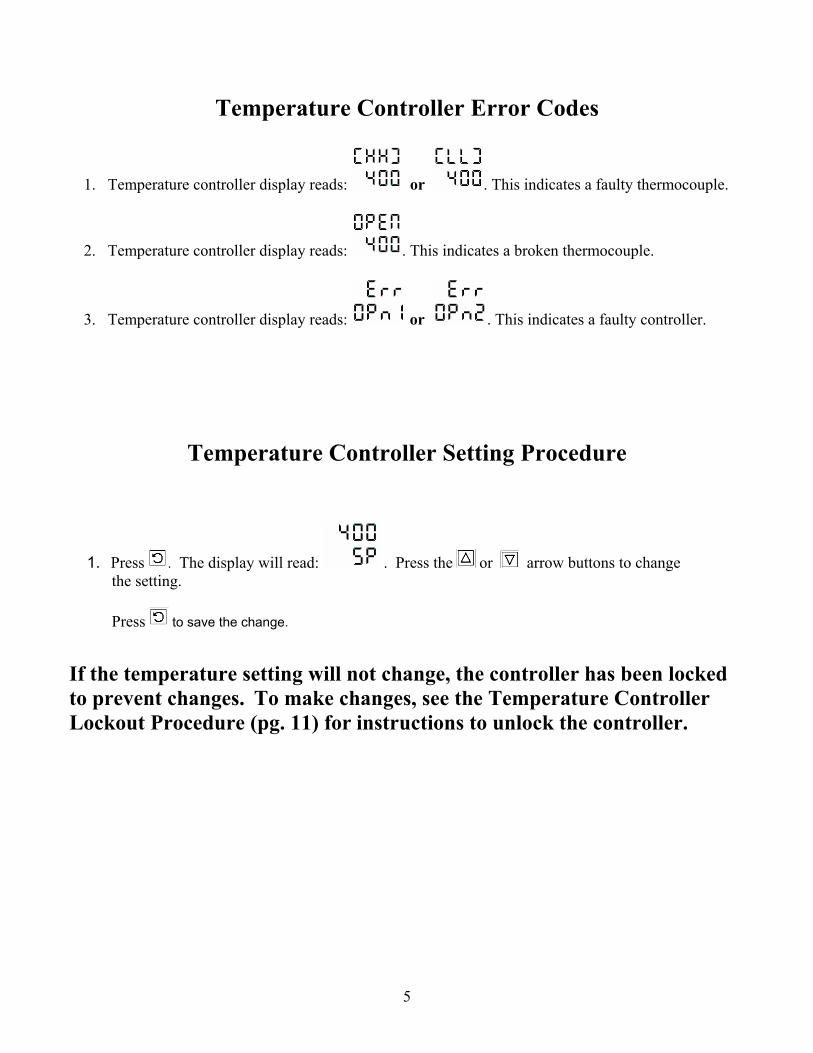
1. Temperature controller display reads: or . This indicates a faulty thermocouple.
2. Temperature controller display reads: . This indicates a broken thermocouple.
3. Temperature controller display reads: or . This indicates a faulty controller.
Temperature Controller Setting Procedure
1. Press . The display will read: . Press the or arrow buttons to change the setting. Press to save the change.
If the temperature setting will not change, the controller has been locked to prevent changes. To make changes, see the Temperature Controller Lockout Procedure (pg. 11) for instructions to unlock the controller.
6
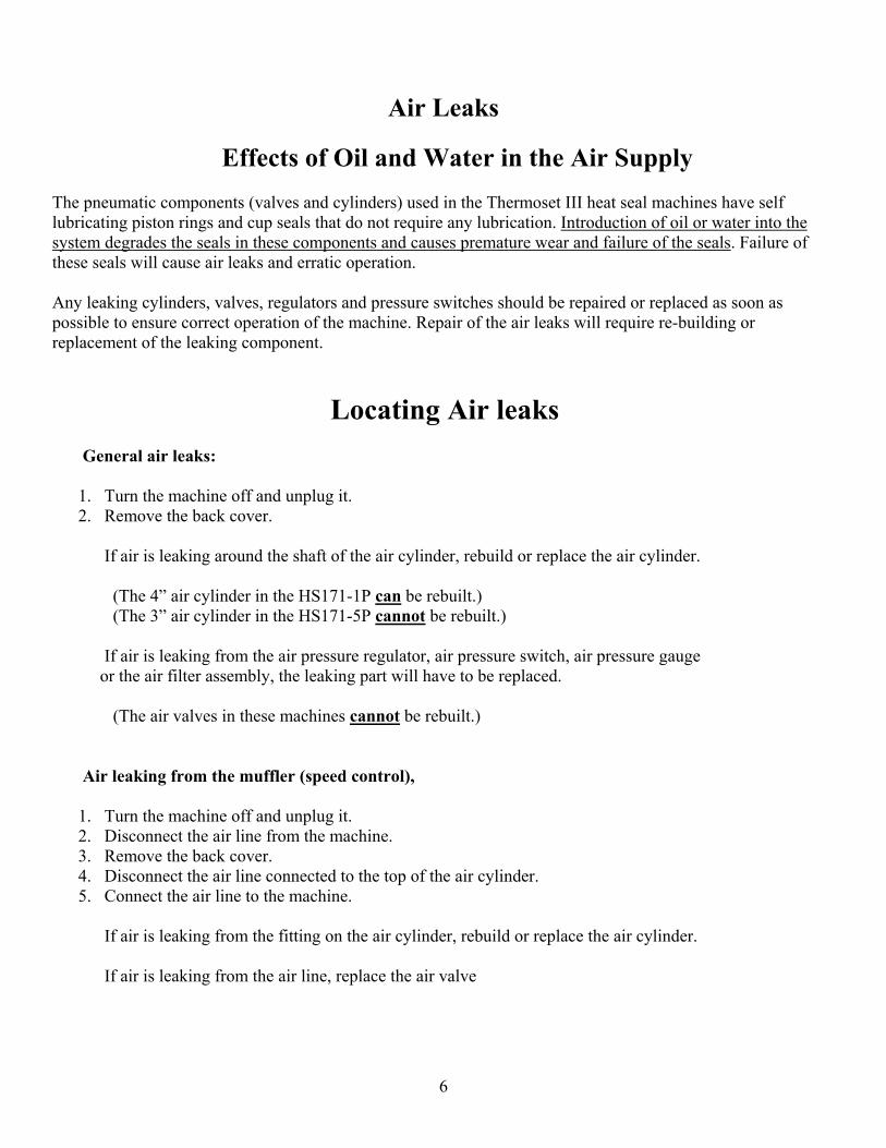
Air Leaks Effects of Oil and Water in the Air Supply The pneumatic components (valves and cylinders) used in the Thermoset III heat seal machines have self lubricating piston rings and cup seals that do not require any lubrication. Introduction of oil or water into the system degrades the seals in these components and causes premature wear and failure of the seals. Failure of these seals will cause air leaks and erratic operation. Any leaking cylinders, valves, regulators and pressure switches should be repaired or replaced as soon as possible to ensure correct operation of the machine. Repair of the air leaks will require re-building or replacement of the leaking component.
Locating Air leaks General air leaks:
1. Turn the machine off and unplug it. 2. Remove the back cover.
If air is leaking around the shaft of the air cylinder, rebuild or replace the air cylinder. (The 4” air cylinder in the HS171-1P can be rebuilt.) (The 3” air cylinder in the HS171-5P cannot be rebuilt.) If air is leaking from the air pressure regulator, air pressure switch, air pressure gauge or the air filter assembly, the leaking part will have to be replaced. (The air valves in these machines cannot be rebuilt.) Air leaking from the muffler (speed control),
1. Turn the machine off and unplug it. 2. Disconnect the air line from the machine. 3. Remove the back cover. 4. Disconnect the air line connected to the top of the air cylinder. 5. Connect the air line to the machine.
If air is leaking from the fitting on the air cylinder, rebuild or replace the air cylinder. If air is leaking from the air line, replace the air valve
7
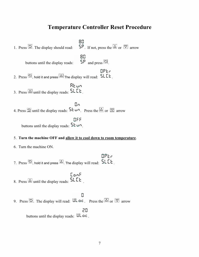
Temperature Controller Reset Procedure
1. Press . The display should read: . If not, press the or arrow
buttons until the display reads: and press .
2. Press , hold it and press The display will read: .
3. Press until the display reads: .
4. Press until the display reads: . Press the or arrow
buttons until the display reads: . 5. Turn the machine OFF and allow it to cool down to room temperature. 6. Turn the machine ON.
7. Press , hold it and press . The display will read: .
8. Press until the display reads: .
9. Press . The display will read: . Press the or arrow
buttons until the display reads: .
8
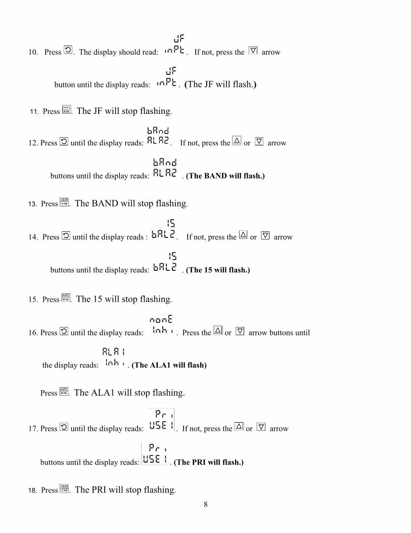
10. Press . The display should read: . If not, press the arrow
button until the display reads: . (The JF will flash.) 11. Press . The JF will stop flashing.
12. Press until the display reads: . If not, press the or arrow
buttons until the display reads: . (The BAND will flash.) 13. Press . The BAND will stop flashing.
14. Press until the display reads : . If not, press the or arrow
buttons until the display reads: . (The 15 will flash.) 15. Press . The 15 will stop flashing.
16. Press until the display reads: . Press the or arrow buttons until
the display reads: . (The ALA1 will flash) Press . The ALA1 will stop flashing.
17. Press until the display reads: . If not, press the or arrow
buttons until the display reads: . (The PRI will flash.) 18. Press . The PRI will stop flashing.
9
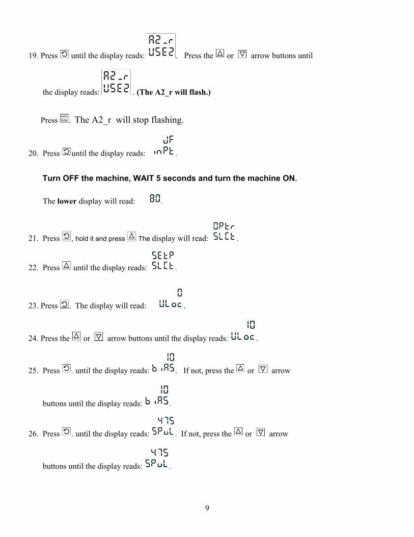
19. Press until the display reads: . Press the or arrow buttons until
the display reads: . (The A2_r will flash.) Press . The A2_r will stop flashing.
20. Press until the display reads: . Turn OFF the machine, WAIT 5 seconds and turn the machine ON.
The lower display will read: .
21. Press , hold it and press The display will read: .
22. Press until the display reads: .
23. Press . The display will read: .
24. Press the or arrow buttons until the display reads: .
25. Press . until the display reads: . If not, press the or arrow
buttons until the display reads: .
26. Press . until the display reads: . If not, press the or arrow
buttons until the display reads: .
10
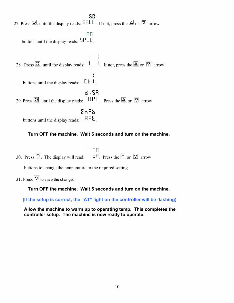
27. Press . until the display reads: . If not, press the or arrow
buttons until the display reads: .
28. Press . until the display reads: . If not, press the or arrow
buttons until the display reads: .
29. Press . until the display reads: . Press the or arrow
buttons until the display reads: . Turn OFF the machine. Wait 5 seconds and turn on the machine.
30. Press . The display will read: . Press the or arrow buttons to change the temperature to the required setting. 31. Press to save the change. Turn OFF the machine. Wait 5 seconds and turn on the machine. (If the setup is correct, the “AT” light on the controller will be flashing) Allow the machine to warm up to operating temp. This completes the controller setup. The machine is now ready to operate.
11
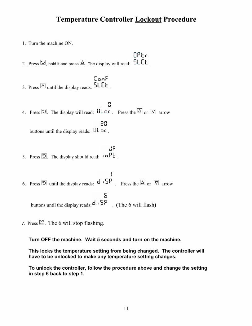
Temperature Controller Lockout Procedure 1. Turn the machine ON.
2. Press , hold it and press . The display will read: .
3. Press until the display reads: .
4. Press . The display will read: . Press the or arrow
buttons until the display reads: .
5. Press . The display should read: .
6. Press until the display reads: . Press the or arrow
buttons until the display reads: . (The 6 will flash) 7. Press . The 6 will stop flashing. Turn OFF the machine. Wait 5 seconds and turn on the machine. This locks the temperature setting from being changed. The controller will have to be unlocked to make any temperature setting changes. To unlock the controller, follow the procedure above and change the setting in step 6 back to step 1.
12
Touch Board Adjustment Procedure
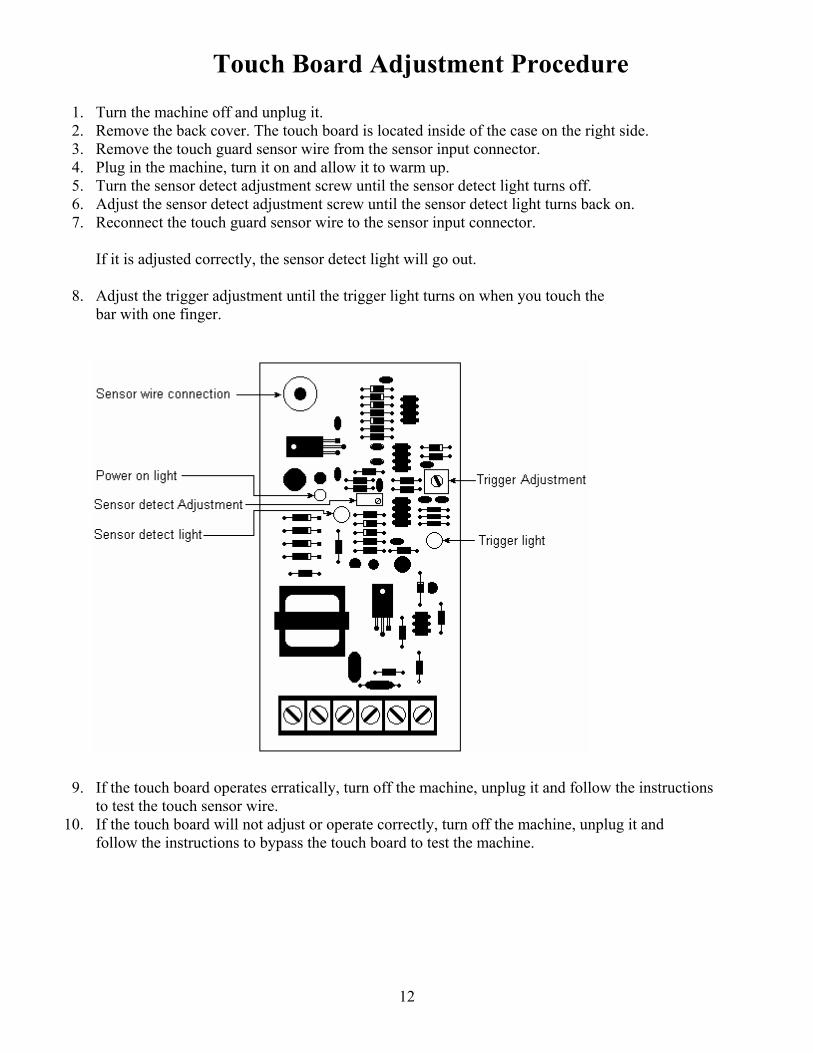
1. Turn the machine off and unplug it. 2. Remove the back cover. The touch board is located inside of the case on the right side.
3. Remove the touch guard sensor wire from the sensor input connector. 4. Plug in the machine, turn it on and allow it to warm up. 5. Turn the sensor detect adjustment screw until the sensor detect light turns off. 6. Adjust the sensor detect adjustment screw until the sensor detect light turns back on. 7. Reconnect the touch guard sensor wire to the sensor input connector. If it is adjusted correctly, the sensor detect light will go out. 8. Adjust the trigger adjustment until the trigger light turns on when you touch the bar with one finger.
9. If the touch board operates erratically, turn off the machine, unplug it and follow the instructions to test the touch sensor wire. 10. If the touch board will not adjust or operate correctly, turn off the machine, unplug it and follow the instructions to bypass the touch board to test the machine.
13
Touch Board Sensor Wire Test Procedure
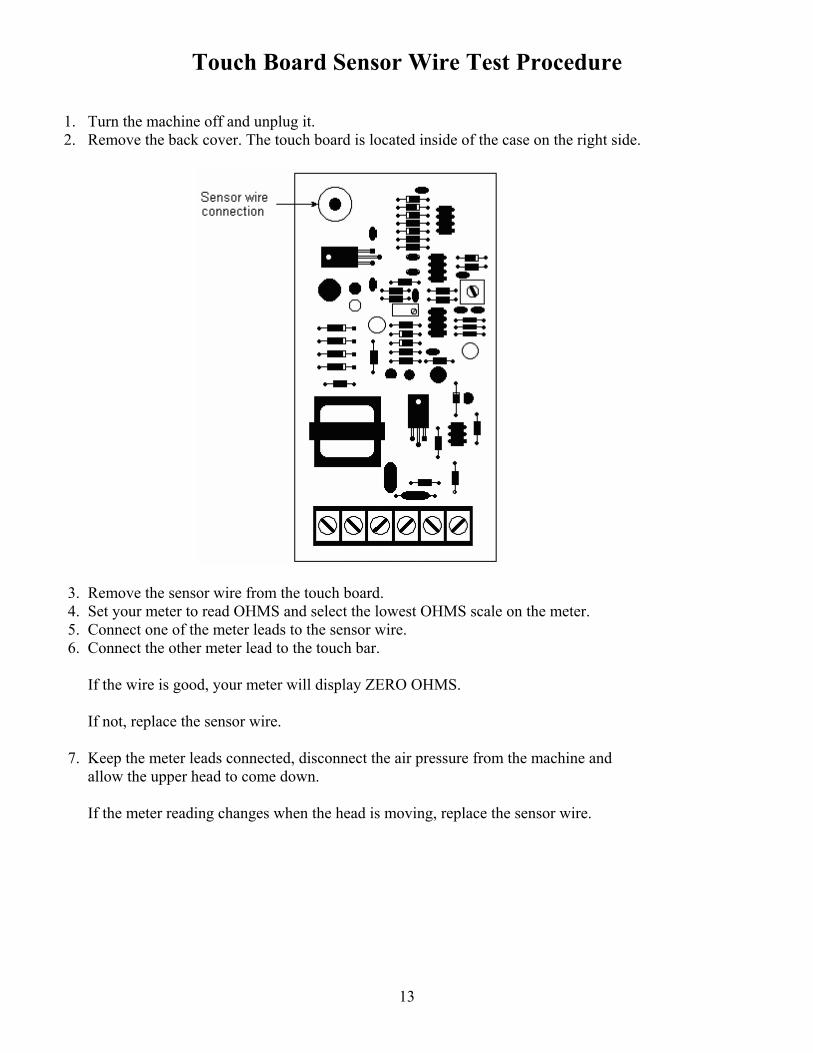
1. Turn the machine off and unplug it. 2. Remove the back cover. The touch board is located inside of the case on the right side.
3. Remove the sensor wire from the touch board. 4. Set your meter to read OHMS and select the lowest OHMS scale on the meter. 5. Connect one of the meter leads to the sensor wire. 6. Connect the other meter lead to the touch bar. If the wire is good, your meter will display ZERO OHMS. If not, replace the sensor wire. 7. Keep the meter leads connected, disconnect the air pressure from the machine and allow the upper head to come down. If the meter reading changes when the head is moving, replace the sensor wire.
14
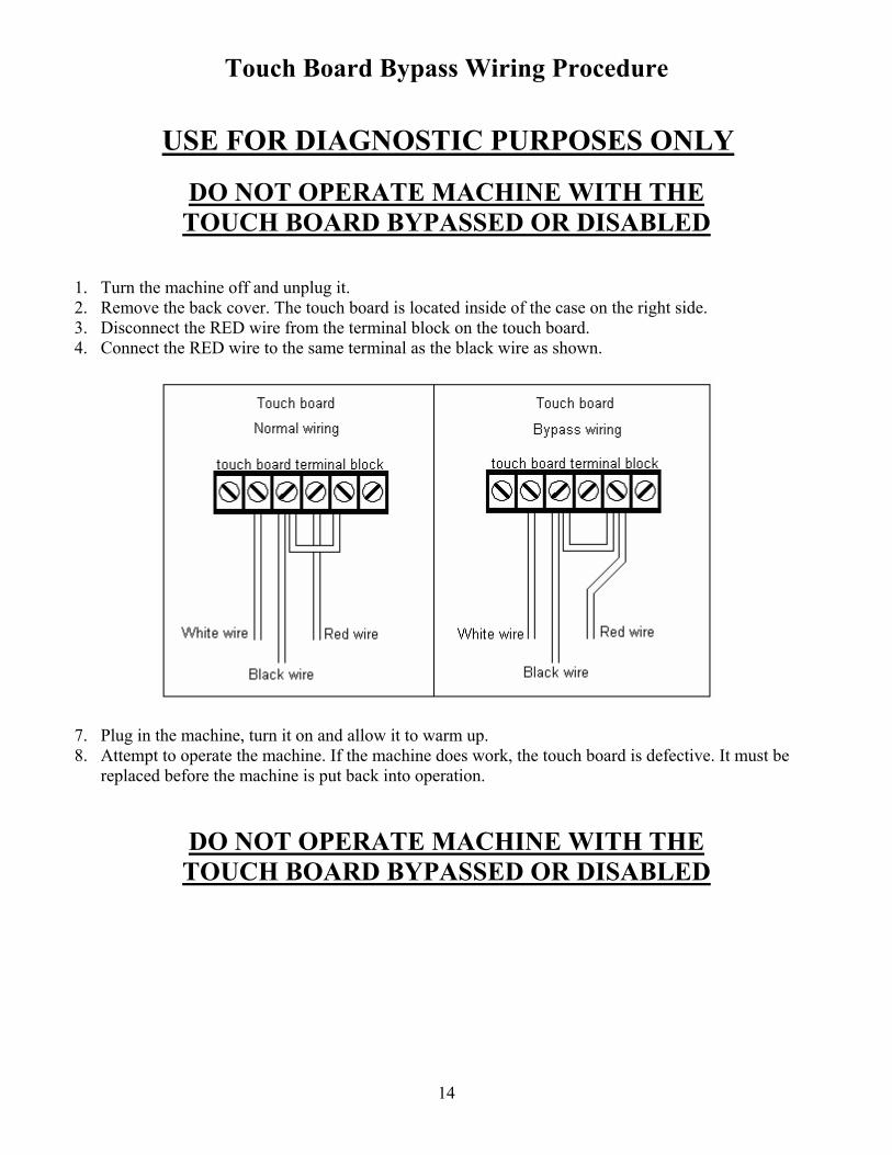
Touch Board Bypass Wiring Procedure
USE FOR DIAGNOSTIC PURPOSES ONLY
DO NOT OPERATE MACHINE WITH THE TOUCH BOARD BYPASSED OR DISABLED
1. Turn the machine off and unplug it. 2. Remove the back cover. The touch board is located inside of the case on the right side. 3. Disconnect the RED wire from the terminal block on the touch board. 4. Connect the RED wire to the same terminal as the black wire as shown.
7. Plug in the machine, turn it on and allow it to warm up. 8. Attempt to operate the machine. If the machine does work, the touch board is defective. It must be replaced before the machine is put back into operation.
DO NOT OPERATE MACHINE WITH THE TOUCH BOARD BYPASSED OR DISABLED
15
ATD Relay & Start Switch Test Procedure ****** CAUTION ****** THIS TEST PROCEDURE REQUIRES THAT THE MACHINE BE PLUGGED IN AND TURNED ON. USE CAUTION WHEN PERFORMING VOLTAGE TESTS.
1. Turn the machine off and unplug it. 2. Remove the back cover. 3. Unplug the ATD relay from the socket and remove it from the machine.
(The ATD relay – blue encasement - is located on the right side of the machine under the touch control board.)
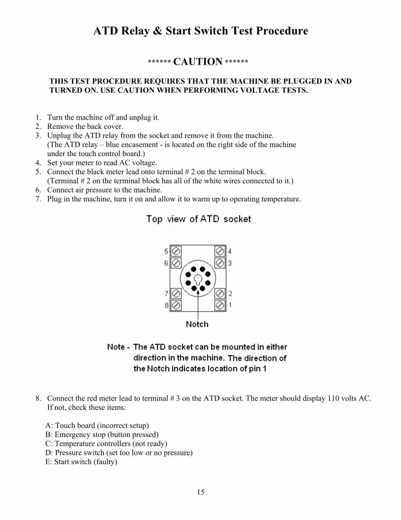
4. Set your meter to read AC voltage. 5. Connect the black meter lead onto terminal # 2 on the terminal block.
(Terminal # 2 on the terminal block has all of the white wires connected to it.) 6. Connect air pressure to the machine. 7. Plug in the machine, turn it on and allow it to warm up to operating temperature.
8. Connect the red meter lead to terminal # 3 on the ATD socket. The meter should display 110 volts AC. If not, check these items: A: Touch board (incorrect setup) B: Emergency stop (button pressed) C: Temperature controllers (not ready) D: Pressure switch (set too low or no pressure) E: Start switch (faulty)
16
9. Have an assistant press both start buttons. When the start buttons are pressed, the voltage on terminal # 3 should display 0 volts AC. If not, one of the start switches is faulty.
10. Remove the red meter lead from terminal # 3 and connect it to terminal # 8 on the ATD socket. The meter should display 0 volts AC.
11. Have an assistant press both start buttons. When the start buttons are pressed, the voltage on terminal # 8 on the ATD socket should display 110 volts AC. If not, one of the start switches is faulty.
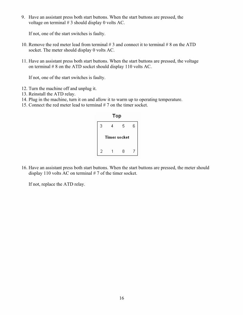
12. Turn the machine off and unplug it. 13. Reinstall the ATD relay. 14. Plug in the machine, turn it on and allow it to warm up to operating temperature. 15. Connect the red meter lead to terminal # 7 on the timer socket.
16. Have an assistant press both start buttons. When the start buttons are pressed, the meter should display 110 volts AC on terminal # 7 of the timer socket. If not, replace the ATD relay.
17
Timer Test Procedure ****** CAUTION ****** THIS TEST PROCEDURE REQUIRES THAT THE MACHINE BE PLUGGED IN AND TURNED ON. USE CAUTION WHEN PERFORMING VOLTAGE TESTS.
1. Turn the machine off and unplug it. 2. Remove the back cover. 3. Set your meter to read AC voltage. 4. Connect the black meter lead onto terminal # 2 on the terminal block.
(Terminal # 2 on the terminal block has all of the white wires connected to it.) 5. Connect air pressure to the machine. 6. Plug in the machine, turn it on and allow it to warm up to operating temperature.
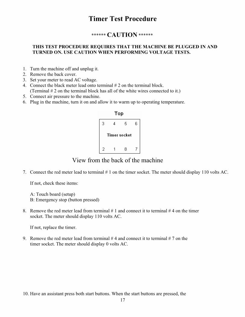
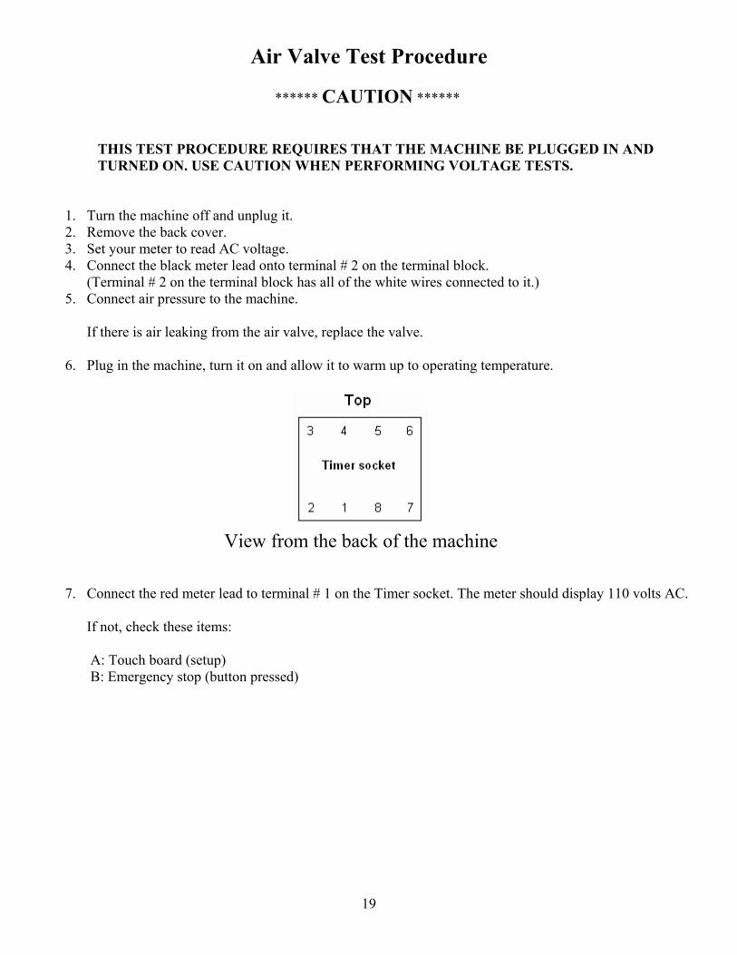
View from the back of the machine
7. Connect the red meter lead to terminal # 1 on the timer socket. The meter should display 110 volts AC. If not, check these items: A: Touch board (setup) B: Emergency stop (button pressed)
8. Remove the red meter lead from terminal # 1 and connect it to terminal # 4 on the timer socket. The meter should display 110 volts AC. If not, replace the timer.
9. Remove the red meter lead from terminal # 4 and connect it to terminal # 7 on the timer socket. The meter should display 0 volts AC.
10. Have an assistant press both start buttons. When the start buttons are pressed, the
18
voltage on terminal # 7 the meter should display 110 volts AC. If not, check these items: A: Temperature controllers (not ready) B: Pressure switch (set too low or no pressure) C: ATD relay (faulty) D: Start switches (faulty)
11. Remove the red meter lead from terminal # 7 and connect it to terminal # 3 on the timer socket. The meter should display 0 volts AC. Have an assistant press both start buttons. When the start buttons are pressed, the voltage on terminal # 3 on the timer socket should display 110 volts AC. If not, replace the timer.
19
Air Valve Test Procedure ****** CAUTION ****** THIS TEST PROCEDURE REQUIRES THAT THE MACHINE BE PLUGGED IN AND TURNED ON. USE CAUTION WHEN PERFORMING VOLTAGE TESTS.
1. Turn the machine off and unplug it. 2. Remove the back cover. 3. Set your meter to read AC voltage. 4. Connect the black meter lead onto terminal # 2 on the terminal block.
(Terminal # 2 on the terminal block has all of the white wires connected to it.) 5. Connect air pressure to the machine.
If there is air leaking from the air valve, replace the valve.
6. Plug in the machine, turn it on and allow it to warm up to operating temperature.
View from the back of the machine
7. Connect the red meter lead to terminal # 1 on the Timer socket. The meter should display 110 volts AC. If not, check these items: A: Touch board (setup) B: Emergency stop (button pressed)
20
8. Remove the red meter lead from terminal # 1 and connect it to terminal # 3 on the timer socket. The meter should display 0 volts AC. Have an assistant press both start buttons. When the start buttons are pressed, the voltage on terminal # 3 on the timer socket should display 110 volts AC. If not, check these items: A: Temperature controllers (not ready) B: Pressure switch (set too low or no pressure) C: ATD relay (faulty) D: Start switches (faulty) E: Timer (faulty) If the meter does display 110 volts AC and the air valve does not operate, replace the valve.
21
Seal Switch Test Procedure
1. Turn the machine off and unplug it. 2. Remove the back cover. 3. Connect air pressure to the machine. 4. Set your meter to read OHMS and select the lowest OHMS scale on the meter.
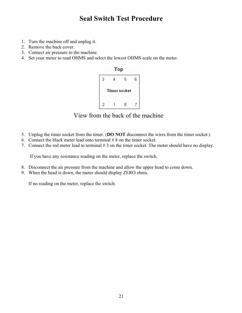
View from the back of the machine
5. Unplug the timer socket from the timer. (DO NOT disconnect the wires from the timer socket.) 6. Connect the black meter lead onto terminal # 8 on the timer socket. 7. Connect the red meter lead to terminal # 3 on the timer socket. The meter should have no display.
If you have any resistance reading on the meter, replace the switch.
8. Disconnect the air pressure from the machine and allow the upper head to come down. 9. When the head is down, the meter should display ZERO ohms.
If no reading on the meter, replace the switch.
22
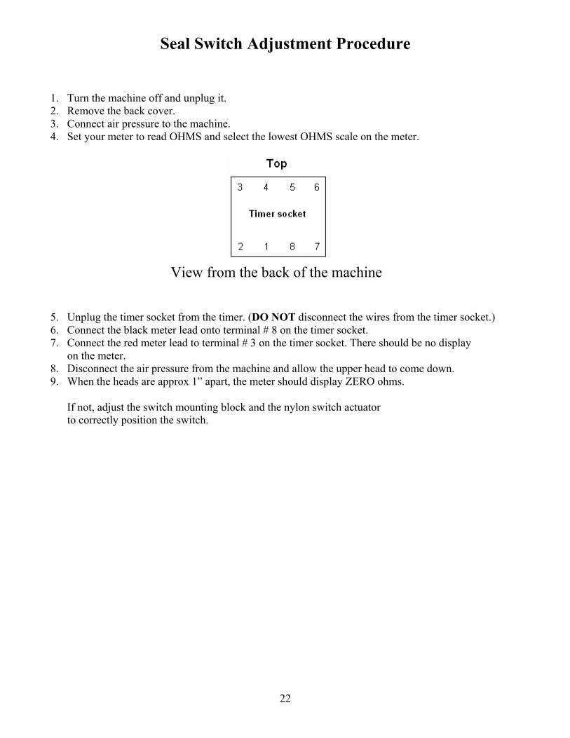
Seal Switch Adjustment Procedure
1. Turn the machine off and unplug it. 2. Remove the back cover. 3. Connect air pressure to the machine. 4. Set your meter to read OHMS and select the lowest OHMS scale on the meter.
View from the back of the machine
5. Unplug the timer socket from the timer. (DO NOT disconnect the wires from the timer socket.) 6. Connect the black meter lead onto terminal # 8 on the timer socket. 7. Connect the red meter lead to terminal # 3 on the timer socket. There should be no display
on the meter. 8. Disconnect the air pressure from the machine and allow the upper head to come down. 9. When the heads are approx 1” apart, the meter should display ZERO ohms.
If not, adjust the switch mounting block and the nylon switch actuator to correctly position the switch.
23
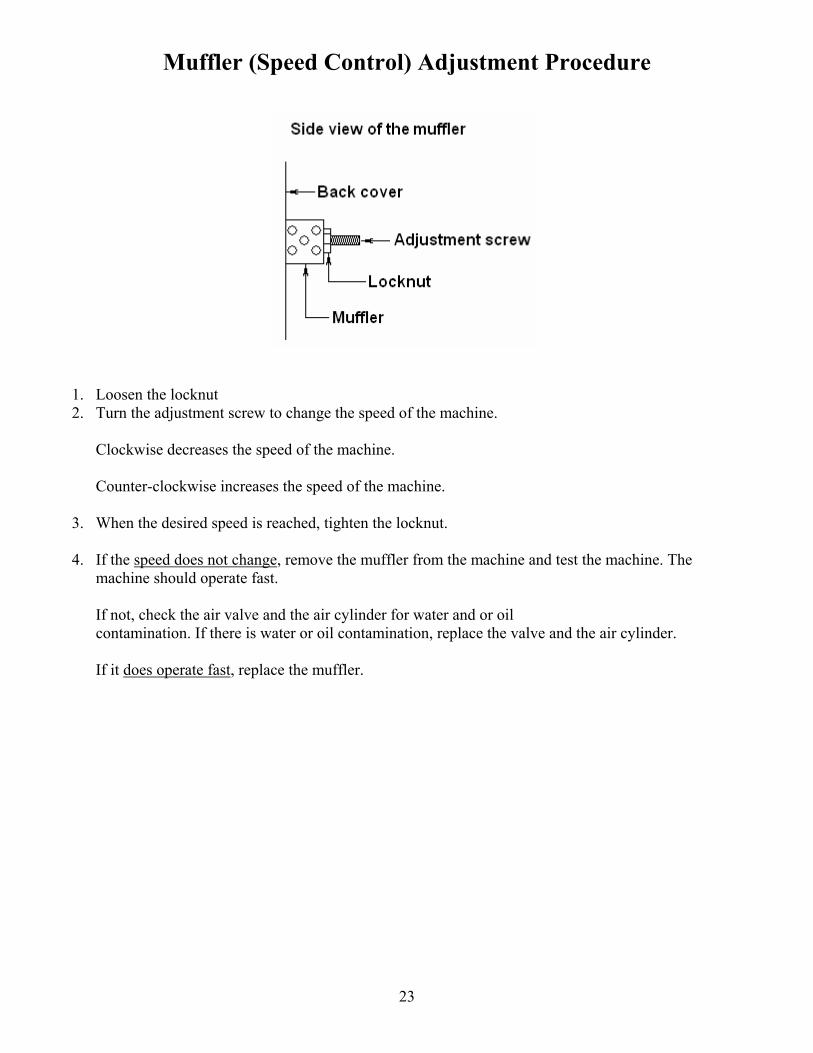
Muffler (Speed Control) Adjustment Procedure
1. Loosen the locknut 2. Turn the adjustment screw to change the speed of the machine.
Clockwise decreases the speed of the machine. Counter-clockwise increases the speed of the machine.
3. When the desired speed is reached, tighten the locknut.
4. If the speed does not change, remove the muffler from the machine and test the machine. The machine should operate fast. If not, check the air valve and the air cylinder for water and or oil contamination. If there is water or oil contamination, replace the valve and the air cylinder. If it does operate fast, replace the muffler.
24
Emergency Stop Switch Test Procedure ****** CAUTION ****** THIS TEST PROCEDURE REQUIRES THAT THE MACHINE BE PLUGGED IN AND TURNED ON. USE CAUTION WHEN PERFORMING VOLTAGE TESTS.
1. Turn the machine off and unplug it. 2. Turning the emergency stop button in the direction of the arrows until it pops out. 3. Remove the back cover. 4. Set your meter to read AC voltage. 5. Connect the black meter lead onto terminal # 2 on the terminal block.
(Terminal # 2 on the terminal block has all of the white wires connected to it.)
6. Plug in the machine and turn it on. 7. Connect the red meter lead to terminal # 3 on the terminal block.
(Terminal # 3 on the terminal block has all of the red wires connected to it.) The meter should read 110 volts AC.
8. If not, turn the machine off and unplug it.
9. Disconnect the red meter lead from terminal # 3 on the terminal block and connect the red meter lead onto the red wire on the touch control board.
10. Plug in the machine and turn it on. You should read 110 volts AC. If the meter displays 110 volts AC, turn the machine off, unplug it and replace the emergency stop switch. If not, turn the machine off, unplug it and follow the instructions to re-adjust the touch board.
25
No Heat Test Procedure ****** CAUTION ****** THIS TEST PROCEDURE REQUIRES THAT THE MACHINE BE PLUGGED IN AND TURNED ON. USE CAUTION WHEN PERFORMING VOLTAGE TESTS.
1. Perform the temperature controller reset procedure. If this does not correct the problem, turn the machine off and unplug it.
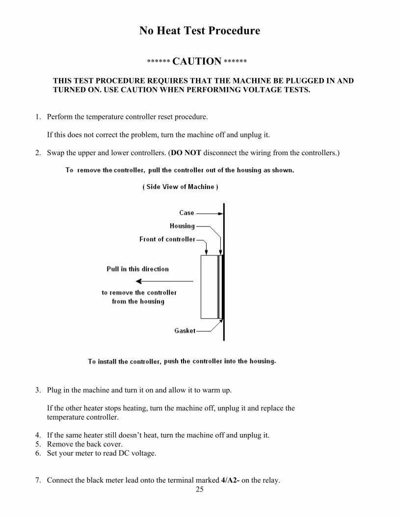
2. Swap the upper and lower controllers. (DO NOT disconnect the wiring from the controllers.)
3. Plug in the machine and turn it on and allow it to warm up. If the other heater stops heating, turn the machine off, unplug it and replace the temperature controller.
4. If the same heater still doesn’t heat, turn the machine off and unplug it. 5. Remove the back cover. 6. Set your meter to read DC voltage.
7. Connect the black meter lead onto the terminal marked 4/A2- on the relay.
26
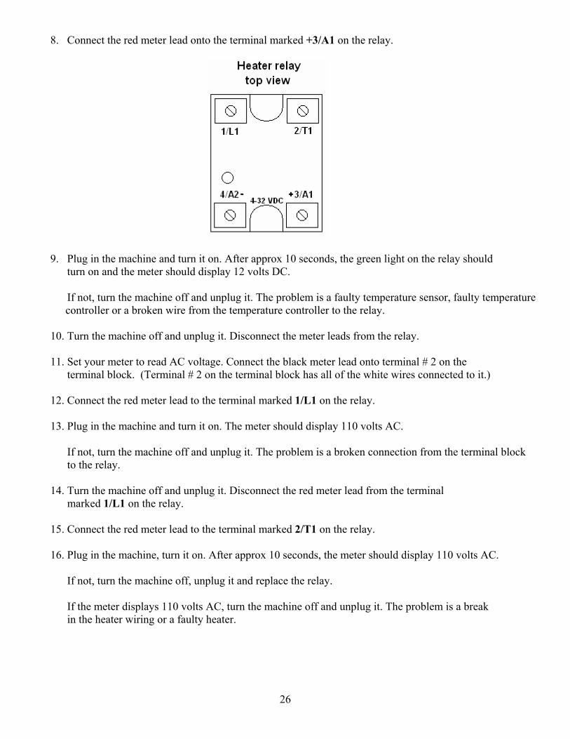
8. Connect the red meter lead onto the terminal marked +3/A1 on the relay.
9. Plug in the machine and turn it on. After approx 10 seconds, the green light on the relay should turn on and the meter should display 12 volts DC.
If not, turn the machine off and unplug it. The problem is a faulty temperature sensor, faulty temperature controller or a broken wire from the temperature controller to the relay.
10. Turn the machine off and unplug it. Disconnect the meter leads from the relay.
11. Set your meter to read AC voltage. Connect the black meter lead onto terminal # 2 on the terminal block. (Terminal # 2 on the terminal block has all of the white wires connected to it.)
12. Connect the red meter lead to the terminal marked 1/L1 on the relay.
13. Plug in the machine and turn it on. The meter should display 110 volts AC.
If not, turn the machine off and unplug it. The problem is a broken connection from the terminal block to the relay.
14. Turn the machine off and unplug it. Disconnect the red meter lead from the terminal
marked 1/L1 on the relay.
15. Connect the red meter lead to the terminal marked 2/T1 on the relay.
16. Plug in the machine, turn it on. After approx 10 seconds, the meter should display 110 volts AC. If not, turn the machine off, unplug it and replace the relay. If the meter displays 110 volts AC, turn the machine off and unplug it. The problem is a break in the heater wiring or a faulty heater.
27
Overheating Test Procedure ****** CAUTION ****** THIS TEST PROCEDURE REQUIRES THAT THE MACHINE BE PLUGGED IN AND TURNED ON. USE CAUTION WHEN PERFORMING VOLTAGE TESTS.
1. Check that the temperature setting is correct. 2. Perform the temperature controller reset procedure.
If this does not correct the problem, turn the machine off and unplug it.
3. Swap the upper and lower controllers. (DO NOT disconnect the wiring from the controllers.)
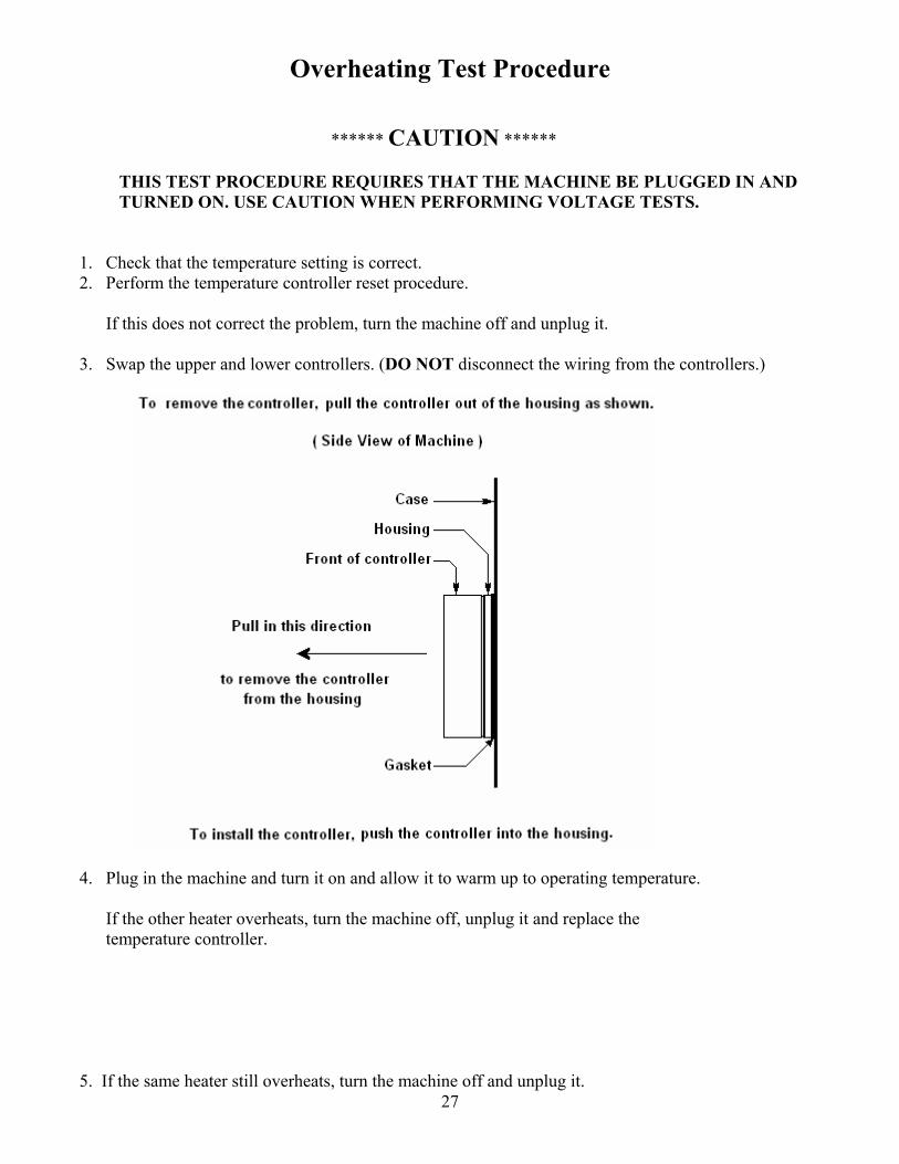
4. Plug in the machine and turn it on and allow it to warm up to operating temperature. If the other heater overheats, turn the machine off, unplug it and replace the temperature controller. 5. If the same heater still overheats, turn the machine off and unplug it.
28
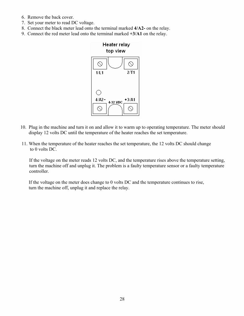
6. Remove the back cover. 7. Set your meter to read DC voltage. 8. Connect the black meter lead onto the terminal marked 4/A2- on the relay. 9. Connect the red meter lead onto the terminal marked +3/A1 on the relay.
10. Plug in the machine and turn it on and allow it to warm up to operating temperature. The meter should display 12 volts DC until the temperature of the heater reaches the set temperature.
11. When the temperature of the heater reaches the set temperature, the 12 volts DC should change to 0 volts DC.
If the voltage on the meter reads 12 volts DC, and the temperature rises above the temperature setting, turn the machine off and unplug it. The problem is a faulty temperature sensor or a faulty temperature controller.
If the voltage on the meter does change to 0 volts DC and the temperature continues to rise, turn the machine off, unplug it and replace the relay.
29
Heater and Wiring Test Procedure
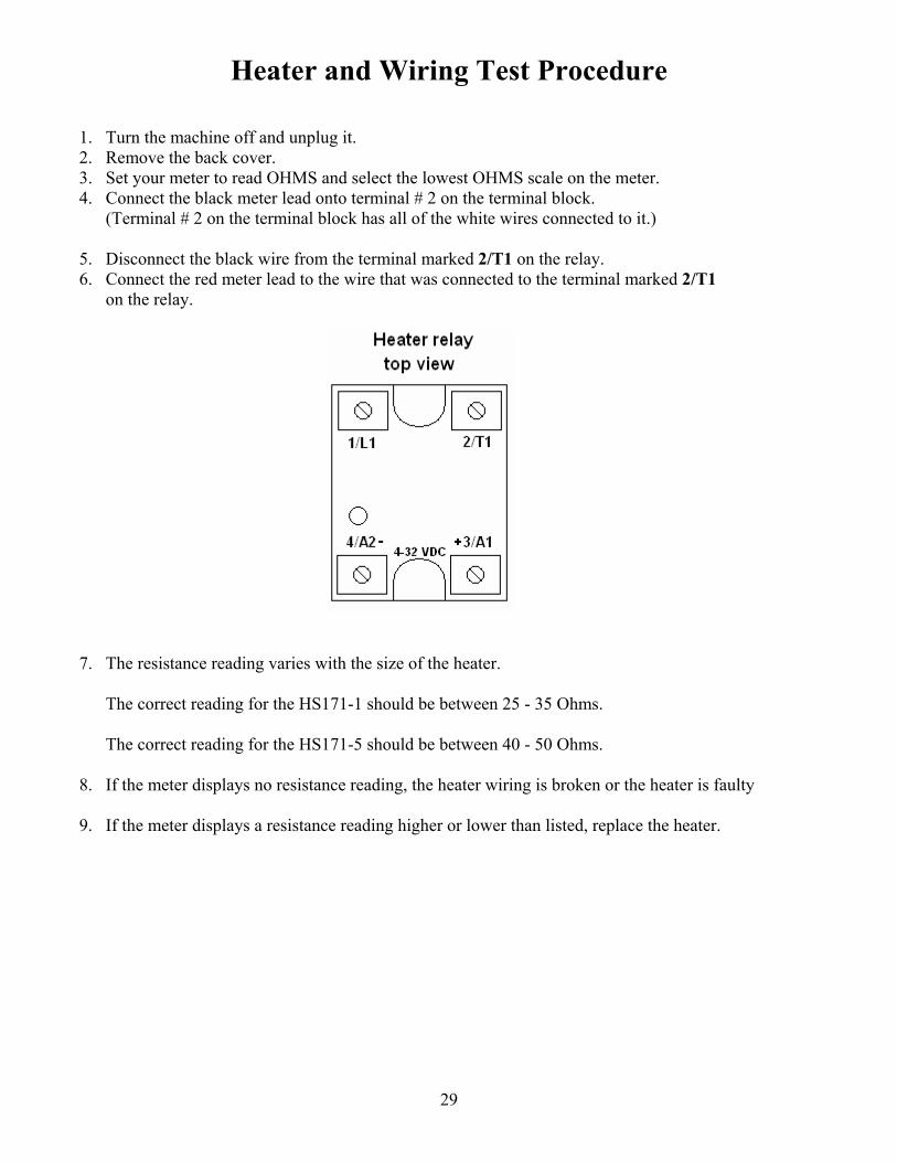
1. Turn the machine off and unplug it. 2. Remove the back cover. 3. Set your meter to read OHMS and select the lowest OHMS scale on the meter. 4. Connect the black meter lead onto terminal # 2 on the terminal block.
(Terminal # 2 on the terminal block has all of the white wires connected to it.)
5. Disconnect the black wire from the terminal marked 2/T1 on the relay. 6. Connect the red meter lead to the wire that was connected to the terminal marked 2/T1
on the relay.
7. The resistance reading varies with the size of the heater. The correct reading for the HS171-1 should be between 25 - 35 Ohms. The correct reading for the HS171-5 should be between 40 - 50 Ohms.
8. If the meter displays no resistance reading, the heater wiring is broken or the heater is faulty
9. If the meter displays a resistance reading higher or lower than listed, replace the heater.
30
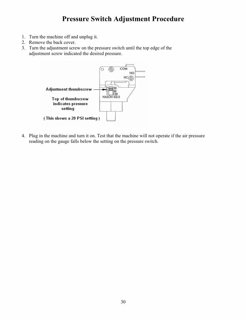
Pressure Switch Adjustment Procedure
1. Turn the machine off and unplug it. 2. Remove the back cover. 3. Turn the adjustment screw on the pressure switch until the top edge of the
adjustment screw indicated the desired pressure.
4. Plug in the machine and turn it on. Test that the machine will not operate if the air pressure reading on the gauge falls below the setting on the pressure switch.
31
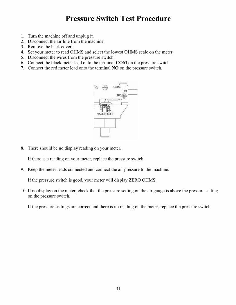
Pressure Switch Test Procedure
1. Turn the machine off and unplug it. 2. Disconnect the air line from the machine. 3. Remove the back cover. 4. Set your meter to read OHMS and select the lowest OHMS scale on the meter. 5. Disconnect the wires from the pressure switch. 6. Connect the black meter lead onto the terminal COM on the pressure switch. 7. Connect the red meter lead onto the terminal NO on the pressure switch.
8. There should be no display reading on your meter. If there is a reading on your meter, replace the pressure switch.
9. Keep the meter leads connected and connect the air pressure to the machine. If the pressure switch is good, your meter will display ZERO OHMS.
10. If no display on the meter, check that the pressure setting on the air gauge is above the pressure setting on the pressure switch.
If the pressure settings are correct and there is no reading on the meter, replace the pressure switch.
32
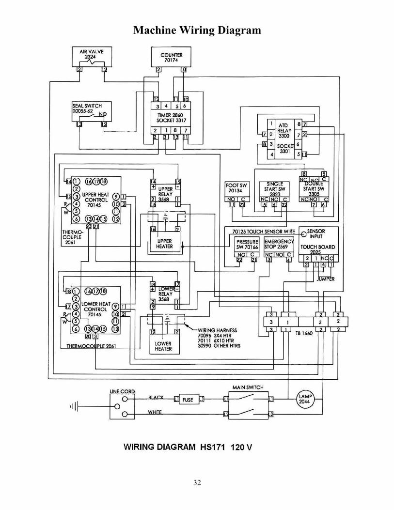
Machine Wiring Diagram


![Detecting faulty rolling-element bearings faulty rolling-element bearings f Faulty rolling-elemen ] t bear- ... such fault iss to regularly mea sure the overall vibration level at](https://img.pdfslide.net/doc/110x75/5b028d597f8b9a65618f638a/detecting-faulty-rolling-element-bearings-faulty-rolling-element-bearings-f-faulty.jpg)