Embed Size (px)
Citation preview
HSDSL, TechnionWinter 2008
Characterization Presentation on:
Skew And Jitter Generating And Measuring System For High Speed Experiments
Undergraduate Project By:Bassel MassadWasseem Zaher
5th March 2008

Agenda
• Definitions
• Project: Background And Objective
• System Architecture: Top Level
• System Analysis: Anchor Element
• Time Table: What next?
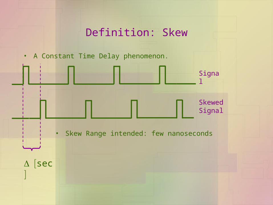
Definition: Skew
• A Constant Time Delay phenomenon.
sec
Signal
Skewed Signal
• Skew Range intended: few nanoseconds
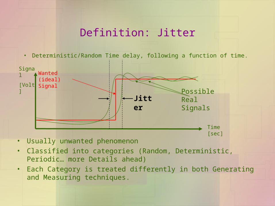
Definition: Jitter
• Deterministic/Random Time delay, following a function of time.
Jitter
Wanted (ideal) Signal
Possible Real Signals
Time [sec]
Signal
[Volt]
• Usually unwanted phenomenon
• Classified into categories (Random, Deterministic, Periodic… more Details ahead)
• Each Category is treated differently in both Generating and Measuring techniques.

Agenda
Definitions
• Project: Background And Objective
• System Architecture: Top Level
• System Analysis: Anchor Element
• Time Table: What next?
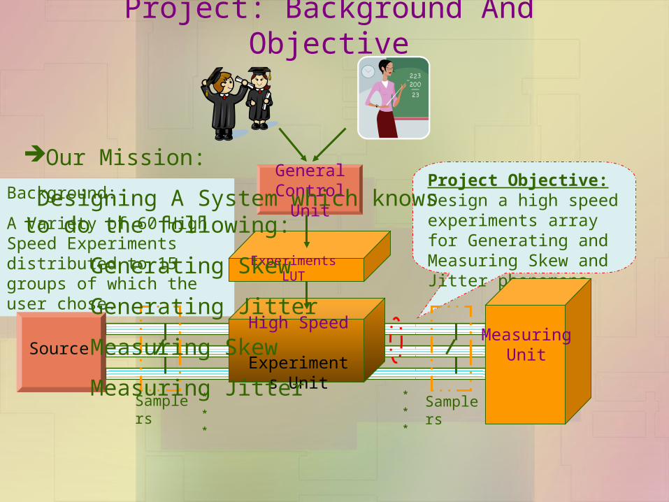
Project: Background And Objective
Project Objective:Design a high speed experiments array for Generating and Measuring Skew and Jitter phenomena
Background:
A Variety of 60 High Speed Experiments distributed to 15 groups of which the user chose.
SourceHigh Speed
Experiments Unit
*
*
*
*
*
*
Samplers Samplers
General Control Unit
MeasuringUnit
Experiments LUT
Our Mission:
Designing A System which knows to do the following:
Generating Skew
Generating Jitter
Measuring Skew
Measuring Jitter

Agenda
Skew Definition Jitter Definition Project: Background And Objective
• System Architecture: Top Level
• System Analysis: Anchor Element
• Time Table: What next?
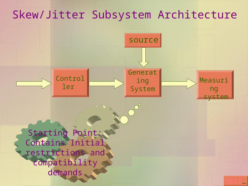
Generating SystemController Measuring
system
Next
Skew/Jitter Subsystem Architecture
Starting Point: Contains Initial restrictions and compatibility demands
source

Inputs fromController
source
Programmable Delay Chip
Skew / Jitter
ReferenceMeasuring
System
Generating UnitBack
To Controller מפצל שעון

Frequency Manipulation
Source From Generating Unit (Frequency=F0)
Commands form Users
Generating System
Controller
Encoding
LUT
Back
F/n
Memories Array
Memories Control
(Addresses,
Memories selection…)
n Select
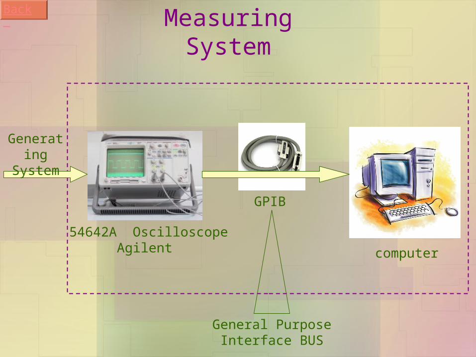
54642A Oscilloscope Agilent
GPIB
computer
Measuring System
Generating System
Back
General Purpose Interface BUS

Agenda
Definitions Project: Background And Objective System Architecture: Top Level
• System Analysis: Anchor Element
• Time Table: What next?
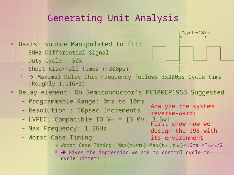
Generating Unit Analysis
• Basis: source Manipulated to fit:– 5MHz Differential Signal
– Duty Cycle = 50%
– Short Rise/Fall Times (~300ps) Maximal Delay Chip Frequency follows 3x300ps Cycle time (Roughly
1.11GHz)
• Delay element: On Semiconductor’s MC100EP195B Suggested
– Programmable Range: 0ns to 10ns
– Resolution : 10psec Increments
– LVPECL Compatible IO VCC = [3.0v, 3.6v]
– Max Frequency: 1.2GHz
– Worst Case Timing:» Worst Case Timing: Max{ts+th}+Max{tPLH,tPHL}<16ns <Tcycle/2 Gives the impression we are to control cycle-to-cycle Jitter!
Tcycle=200ns
Analyze the system reverse-ward:
First show how we design the 195 with its environment

Agenda
Definitions Project: Background And Objective System Architecture: Top Level System Analysis: Anchor Element
• Time Table: What next?
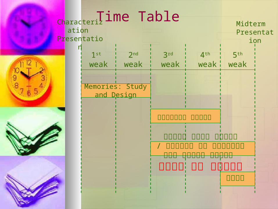
Time Table
1st weak
2nd
weak3rd
weak4th
weak5th
weak
Characterization Presentation
Midterm Presentation
Memories: Study and Design
חקירת דרכי מדידה ותיאומם עם המערכת / בניית מחלקי תדר
לשאול את יוסי
מצגת
בניית מצביעים