Embed Size (px)
Citation preview
IEEE 802.3 Higher Speed Study Group - DRAFT TUTORIAL
HSSG DRAFT TUTORIALMAC / PHY
John Jaeger, Infinera

39IEEE 802.3 Higher Speed Study Group - DRAFT TUTORIAL
Overview – 100G MAC & PHY
• Consistent with previous Ethernet rates, extension to 40,000 & 100,000 Mb/s data rates• Frame format; Services; Management attributes
• MAC• Proposing no changes to the MAC operation• Technical feasibility material reviewed:
• CRC checker, general MAC functions, gear-boxes, host interfaces – roll-ups at .13um & 90nm data points
• No issues or concerns identified• PCS
• Specified PCS(s) need to accommodate:• 40G backplane PHY; 40 & 100G copper cable PHYs;
40 & 100G MMF PHYs and 100G SMF PHYs• Commonality, leveraging existing 10G technology,
and working with the specified multi-channel/cable/fiber/wavelength PMDs will be examined
• Two example approaches reviewed (next slides)
PCS
PMA
PMD
LLC
MACReconciliation
Medium
Generalized LANCSMA/CD Layers

40IEEE 802.3 Higher Speed Study Group - DRAFT TUTORIAL
CTBI Technical Overview
100G64B66BEncode
100GX^58Scrm
CTBI I/F(InvMux)
CTBI I/F(deskew,reorder,
mux)
100GX^58
De-scrm
100G64B66BDecode
Tx PCS Tx PMA/PMD Rx PMA/PMD Rx PCS
10:n n:10
n lanes(fiber or wavelengths)
• Standard 64B/66B PCS (running up to 10x faster)• 100G Example: 10 Lane Electrical PCS to PMA/PMD Interface (CTBI)
• 64B/66B aggregate is inverse mux’ed to Virtual Lanes • A unique identifier is added to each Virtual Lane on a periodic basis• Virtual lanes are bit mapped to/from the 10 CTBI electrical lanes• Virtual lane alignment and skew compensation is done in Rx PCS only
• PMA maps 10 lane CTBI to n lane PMD• PMA is simple bit level muxing and demuxing• no realignment in PMA (for either electrical or optical skew)
• PCS and Virtual Lane overhead is very low, and independent of frame size

41IEEE 802.3 Higher Speed Study Group - DRAFT TUTORIAL
APL Technical Overview
• The PME aggregation concept from 802.3ah can be used with existing 10GBASE PHYs– Aggregation at the Physical Layer (APL)
• Variety of fragment format considerations discussed (header, size, fragment CRC…)• APL:
• Assumes equal speed links, point-to-point, & full duplex links• Resilient and scalable• Ensures ordered delivery and detects lost or corrupted fragments• Minimal added latency• Fits well with multi-port (quad/octal) PHYs
• An APL control protocol would be specified
Multi-wavelength PHY Example (nxXAUI)
42IEEE 802.3 Higher Speed Study Group - DRAFT TUTORIAL
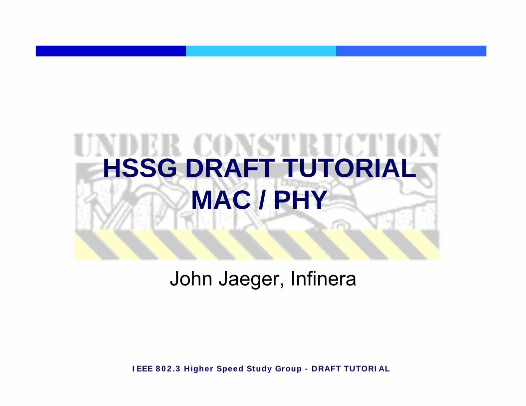
Physical Layer Specifications to be Defined
√At least 1m backplane
√√At least 10m cu cable
√√At least 100m OM3 MMF
√At least 10km SMF
40G
√At least 40km SMF
100G

IEEE 802.3 Higher Speed Study Group - DRAFT TUTORIAL
Draft HSSG Tutorial MMF Section
Jack Jewell – JDSU
44IEEE 802.3 Higher Speed Study Group - DRAFT TUTORIAL
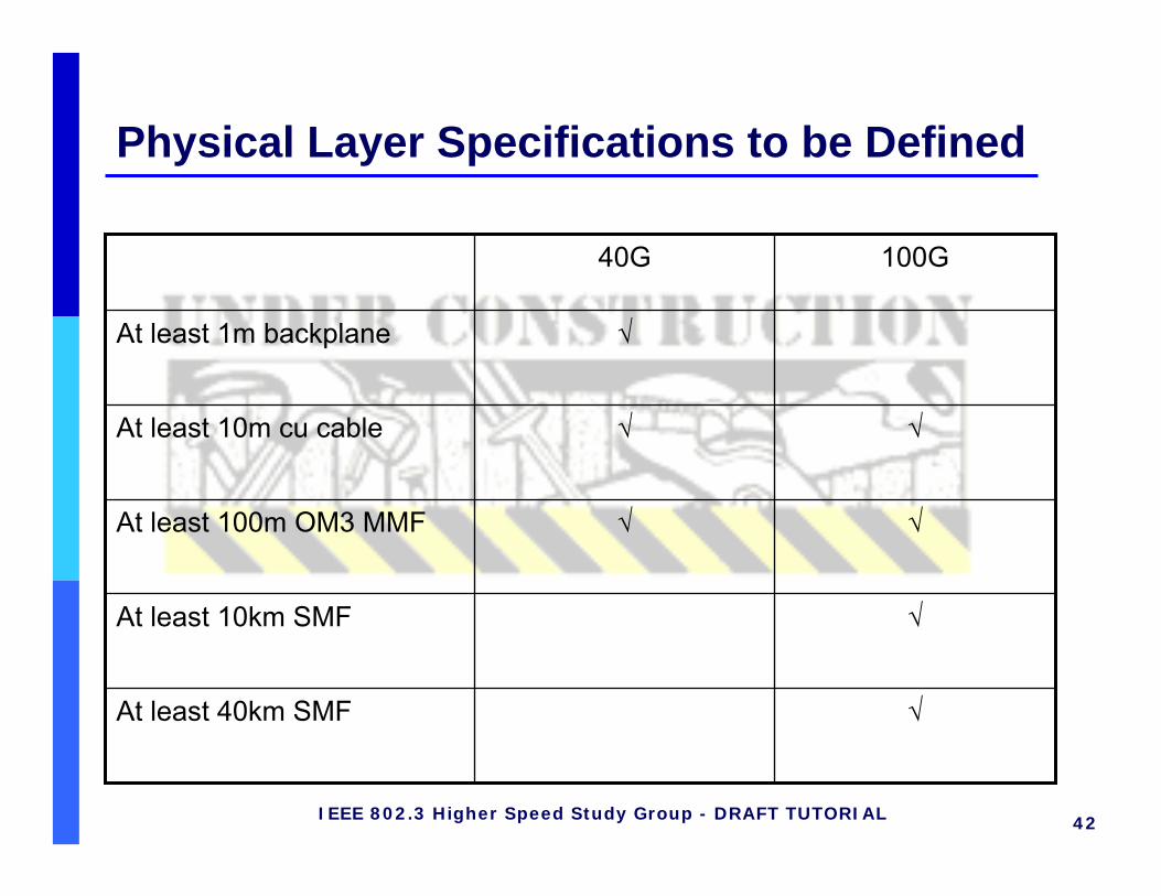
MMF PMD Review (40G and 100G)• Objective: At least 100m on OM3 MMF (40G and 100G)• Platform: Parallel fibers; ~10Gbps/ch; 850nm VCSEL arrays
• Combines existing 10GbE serial and 12x2.7G (or (4+4)x2.5G) parallel product technologies - both are technically sound and economical
• Considering 10x10.3Gbaud (64/66), 12x10Gbaud (8B/10B), others• Considering WDM (e.g. 2 λ‘s) to reduce fiber count/cost
• Advantages:• Low power for ~100m reach - initially ~3W (~1.5W) for 100G (40G)• Small footprint for high-density interconnects• Low cost
• Early Demo: 12x10GbE; >300m by IBM/Picolight; OFC 2003
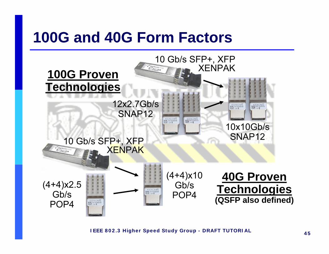
45IEEE 802.3 Higher Speed Study Group - DRAFT TUTORIAL
100G and 40G Form Factors
100G Proven Technologies
10x10Gb/sSNAP1210 Gb/s SFP+, XFP
XENPAK
(4+4)x10Gb/sPOP4
12x2.7Gb/sSNAP12
(4+4)x2.5 Gb/sPOP4
40G Proven Technologies(QSFP also defined)
10 Gb/s SFP+, XFPXENPAK

46IEEE 802.3 Higher Speed Study Group - DRAFT TUTORIAL
Economic Feasibility - VCSEL Yield10x10G VCSEL yield is necessary for cost feasibility
• VCSEL array is only a small portion of a 10x10G overall cost (same applies to 1x10G and 12x2.7G)
• Random microscale fallout:• 12x a small number is still a small number - not significant factor
• Areal-dependent performance fallout:• Affects 1x and 12x similarly (slight penalty for 12x, less for 4x)
Array yield will not be a significant cost factor
1
1.5
2
2.5
0 1 2 3 4 5% Random fallout
Cos
t mul
tiplie
r 1x12x 1x12
Array size
1x4 yield slightly higher than 1x12

47IEEE 802.3 Higher Speed Study Group - DRAFT TUTORIAL
Technical Feasibility - VCSEL ReliabilityWearout Time (Depends on uniformity)
• Perfect uniformity → 12x same as 1x• Exp. reports: 12x wearout time ~1/2 as for 1x
Random Failures• 12x array failure rate nearly 12 times the 1x failure rate• Virtually all “random” failures are eliminated through burn-in
ESD-Related Failures• Above-threshold ESD events damage 1x and 12x about equally
Non-Hermetic Packaging• 12x3G VCSELs robust to harsh environments
0
0.5
1
1.5
2
2.5
3
0 Time (h)
delta
Ith
(dB
)
Time (hours)
Power @ 7mA (mW)
48IEEE 802.3 Higher Speed Study Group - DRAFT TUTORIAL
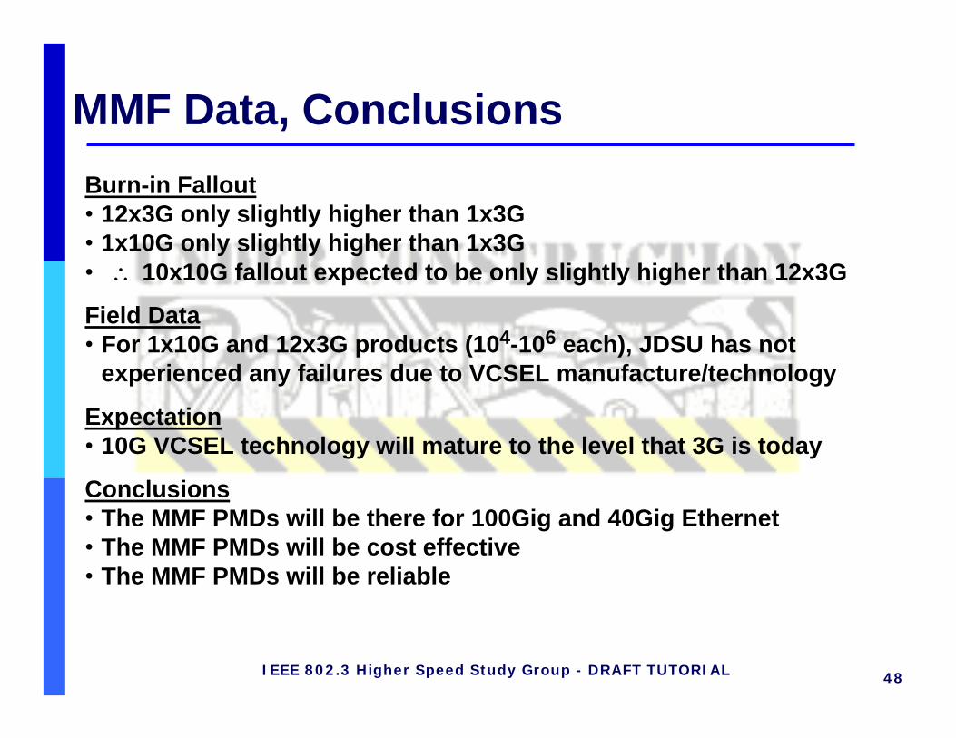
MMF Data, ConclusionsBurn-in Fallout• 12x3G only slightly higher than 1x3G• 1x10G only slightly higher than 1x3G• ∴ 10x10G fallout expected to be only slightly higher than 12x3G
Field Data• For 1x10G and 12x3G products (104-106 each), JDSU has not
experienced any failures due to VCSEL manufacture/technology
Expectation• 10G VCSEL technology will mature to the level that 3G is today
Conclusions• The MMF PMDs will be there for 100Gig and 40Gig Ethernet• The MMF PMDs will be cost effective• The MMF PMDs will be reliable

IEEE 802.3 Higher Speed Study Group - DRAFT TUTORIAL
Draft HSSG Tutorial SMF Section
Chris Cole – Finisar

50IEEE 802.3 Higher Speed Study Group - DRAFT TUTORIAL
SMF PMD Technical Alternatives
OA + DC
fisher_01_0107
+ DCOA + DC1x100G SerialML
OA + DCduelk_01_0107takeda_01_0107
+ DCOA + DC2x50G DQPSKML
OA + DCOAcole_01_0507jiang_01_0507traverso_01_0307
cole_01_0307jiang_01_0407 traverso_02_0307
5x20G / 4x25GML
OA + DCOAcole_01_1106traverso_02_0307
5x20G / 4x25GDML
OA
jaeger_01_0107martin_01_0307
OA10x10GML
OAschrans_01_0107tsumura_foah_1206
clairardin_01_0107hartman_01_0107
OA10x10GDML
40km1550nm
10km1550nm
40km1310nm
10km1310nm
SMFTechnology
• OA = Optical Amplification (or APD), DC = Dispersion Compensation• Green shading designates alternatives under consideration by HSSG contributors.
51IEEE 802.3 Higher Speed Study Group - DRAFT TUTORIAL
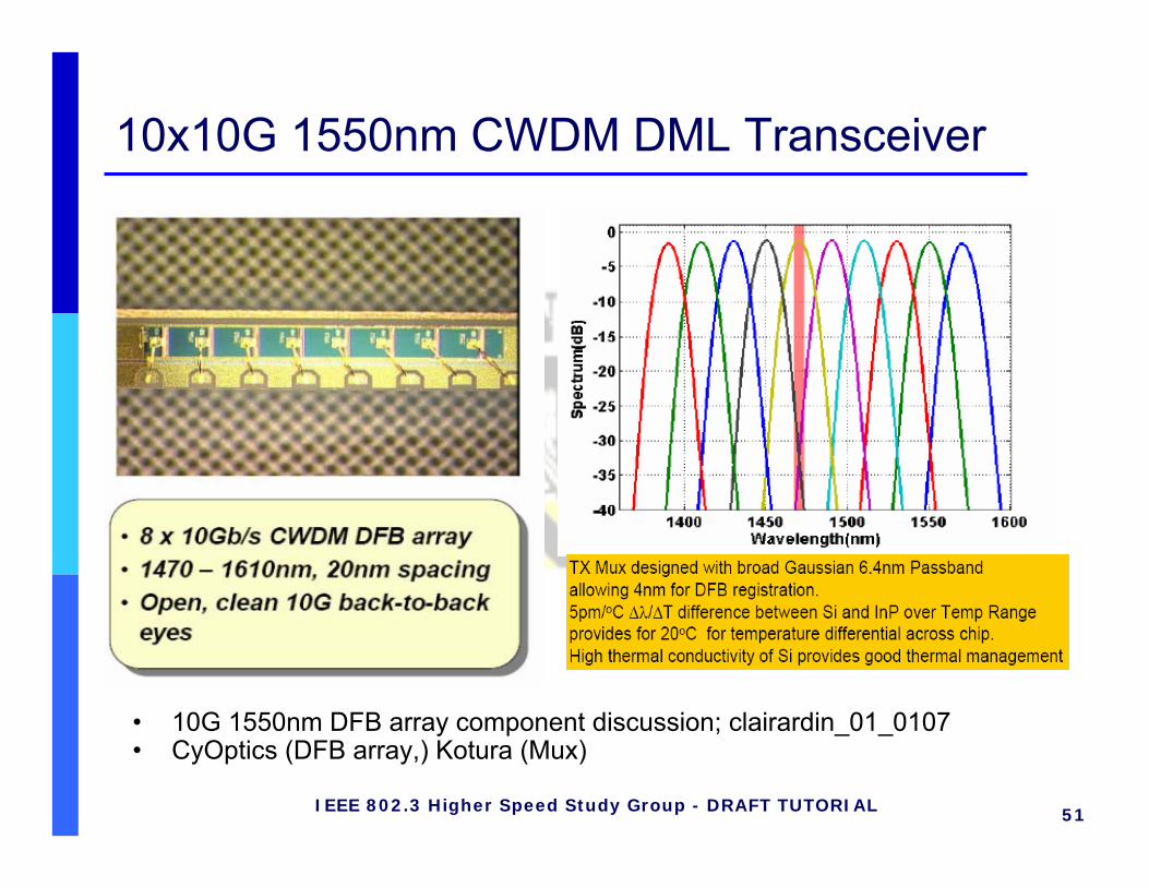
10x10G 1550nm CWDM DML Transceiver
• 10G 1550nm DFB array component discussion; clairardin_01_0107• CyOptics (DFB array,) Kotura (Mux)
52IEEE 802.3 Higher Speed Study Group - DRAFT TUTORIAL
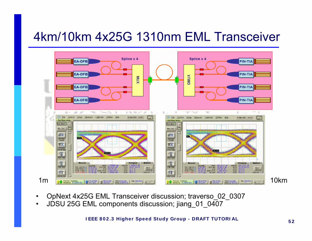
4km/10km 4x25G 1310nm EML Transceiver
• OpNext 4x25G EML Transceiver discussion; traverso_02_0307• JDSU 25G EML components discussion; jiang_01_0407
10km1m

53IEEE 802.3 Higher Speed Study Group - DRAFT TUTORIAL
40km 4x25G 1310nm EML OA Transceiver
• Finisar 1310nm Optical Amplification discussion; cole_01_0507
4:1WDMMUX
1:4WDMDe-
MUX
Micro-ControllerFirmware I/O
RXLANE3
RXLANE1
RXLANE5
RXLANE7
RXLANE9
TXLANE0
TXLANE3
TXLANE5
TXLANE7
TXLANE9
RX_LOS
TX_DIS
SMF
TEC
MD
MD
MD
MDTXLANE1TXLANE2
TXLANE4
TXLANE6
TXLANE8
RXLANE8
RXLANE6
RXLANE4
RXLANE2
RXLANE0
5:2Serializer
5:2Serializer
10x10G
SMF
SOA
Hardware I/O
EML
EML
EML
EML
2:5De-
Serializer
2:5De-
Serializer
TIA
TIA
TIA
TIA
PIN
PIN
PIN
PIN
25G
25G
25G
25G
25G
25G
25G
25G
SOA
REFCLK
RX_DCK
25G
-26
-25
-24
-23
-22
-21
-20
-19
-18
12 14 16 18 20 22 24
SOA Gain optical dB
Sens
itivi
ty d
Bm
30 nm NF=8 PsdB4 nm NF=8 PsdB0.65nm NF=8 PsdB30 nm NF=6 PsdB4 nm NF=6 PsdB0.65nm NF=6 PsdB
Required -22dBm Receiver Sensitivity is achievable with SOA technology.

54IEEE 802.3 Higher Speed Study Group - DRAFT TUTORIAL
10x10G 1550nm DWDM EML Transceiver
• Infinera 100Gbps 1550nm PIC components; jaeger_01_0107.• Example of future cost reduction approach for high volume applications.
55IEEE 802.3 Higher Speed Study Group - DRAFT TUTORIAL
Tutorial Material:HSSG Copper
Chris Di Minico
56IEEE 802.3 Higher Speed Study Group - DRAFT TUTORIAL
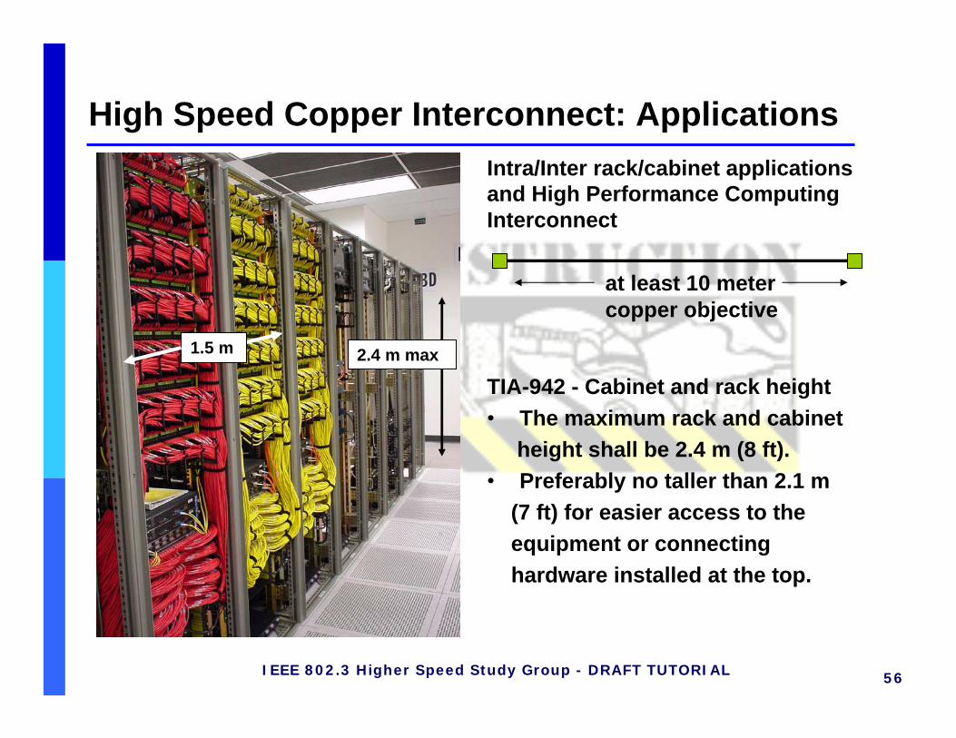
High Speed Copper Interconnect: ApplicationsIntra/Inter rack/cabinet applicationsand High Performance ComputingInterconnect
TIA-942 - Cabinet and rack height• The maximum rack and cabinet
height shall be 2.4 m (8 ft).• Preferably no taller than 2.1 m
(7 ft) for easier access to the equipment or connecting hardware installed at the top.
2.4 m max1.5 m
at least 10 meter copper objective

57IEEE 802.3 Higher Speed Study Group - DRAFT TUTORIAL
at least 10 meter interconnect
•100 ohm 8 pairs – 16 conductors
•12-Fiber OFNP Fiber Optic Cable 4.4 mm (0.17 in)•24-Fiber OFNP Fiber Optic Cable 8.3 mm (0.33 in)
•250 µm - 12-fibers groups for use with multifiber connectors
•28 AWG - 5.6 mm-7.2 mm (0.220 in – 0.281 in) – Leoni twinaxial designs
Twinaxial copper cable assembly

58IEEE 802.3 Higher Speed Study Group - DRAFT TUTORIAL
Cable assemblies - 28 AWG/24 AWG/28 AWG ADV-D 10 meter
0
20
40
60
80
100
120
140
0 2000 4000 6000 8000 10000 12000 14000
MHz
dB
worst case IL - 10 m - 28 AWG
PSNEXT-4 disturber assembly
PSFEXT-3 disturber-10 m assembly
PS Total disturber Noise
Insertion Loss - 10 m - scaled 24AWG
Insertion Loss ADV-D 28 AWG
Leoni twinaxial cable:advanced designs in comparison to nominal CX4/Infiniband constructionsboth electrical and mechanical
Source: Leoni High Speed Cables
59IEEE 802.3 Higher Speed Study Group - DRAFT TUTORIAL
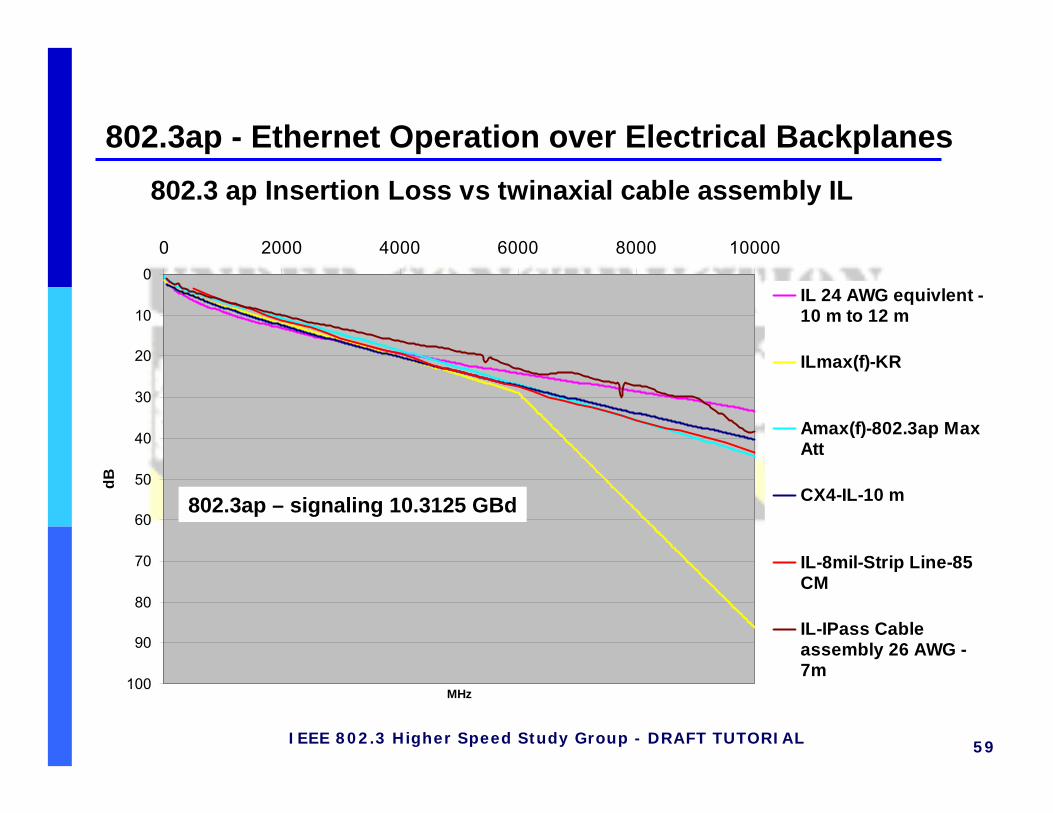
802.3ap - Ethernet Operation over Electrical Backplanes802.3 ap Insertion Loss vs twinaxial cable assembly IL
0
10
20
30
40
50
60
70
80
90
100
0 2000 4000 6000 8000 10000
MHz
dB
IL 24 AWG equivlent -10 m to 12 m
ILmax(f)-KR
Amax(f)-802.3ap MaxAtt
CX4-IL-10 m
IL-8mil-Strip Line-85CM
IL-IPass Cableassembly 26 AWG -7m
802.3ap – signaling 10.3125 GBd

60IEEE 802.3 Higher Speed Study Group - DRAFT TUTORIAL
Various levels de-emphasis without equalization
Eye Patterns for 24 AWG cable -10 to 12 meters
Source: Herb Van Deusen, W.L. Gore
Source: Herb Van Deusen, W.L. Gore

61IEEE 802.3 Higher Speed Study Group - DRAFT TUTORIAL
Lane Rate, Signaling rate, channel bandwidth10 m cable + connectors @ 6 dB Margin
Source: George Zimmerman, Solarflare Communications, Chris DiMinico, MC Communications
Maximum Lane rate
Maximum signaling
rate
Info bits/baud/
dim
Modulated Info bits/baud/dim
(2)
Channel bandwidth
(1)
Copper Gauge
Code gain Length Modulation
Mb/s Mbaud MHz AWG dB meters10889.28 8180.00 1.33 1.33 4090.00 28 0 10 PAM-313984.52 9476.64 1.38 1.48 4738.32 28 2 10 PAM-417555.24 10097.78 1.55 1.74 5048.89 28 4 10 PAM-424950.75 17290.00 1.44 1.44 8645.00 24 0 10 PAM-430727.91 16261.68 1.77 1.89 8130.84 24 2 10 PAM-436785.11 16888.89 1.94 2.18 8444.44 24 4 10 PAM-517212.31 13210.00 1.30 1.30 6605.00 28 ADVD 0 10 PAM-322044.24 13626.17 1.51 1.62 6813.08 28 ADVD 2 10 PAM-427147.01 13742.22 1.76 1.98 6871.11 28 ADVD 4 10 PAM-4
(1)Channel bandwidth=.5*(Maximum signaling rate) (2)Infor/bits/baud/dim adjusted for coding gain
Maximum Lane rate
Maximum signaling
rate
Info bits/baud/
dim
Modulated Info bits/baud/dim
Channel bandwidth
Copper Gauge
Code gain Length Signaling
Mb/s Mbaud MHz AWG dB meters10439.00 10439.00 1.00 1.00 5219.50 28 0 10 PAM-2/NRZ12630.13 13580.00 0.93 1.00 6790.00 28 2 10 PAM-2/NRZ14857.53 16690.00 0.89 1.00 8345.00 28 4 10 PAM-2/NRZ21639.98 21639.98 1.00 1.00 10819.99 24 0 10 PAM-2/NRZ23439.51 25170.00 0.93 1.00 12585.00 24 2 10 PAM-2/NRZ24885.04 27950.00 0.89 1.00 13975.00 24 4 10 PAM-2/NRZ16224.36 16224.36 1.00 1.00 8112.18 28 ADVD 0 10 PAM-2/NRZ18748.43 20159.60 0.93 1.00 10079.80 28 ADVD 2 10 PAM-2/NRZ21194.44 23813.98 0.89 1.00 11906.99 28 ADVD 4 10 PAM-2/NRZ
maximum achievable lane rate for each coding gain
maximum achievable lane rate for each coding gain that yields 1 bit/baud

62IEEE 802.3 Higher Speed Study Group - DRAFT TUTORIAL
• Technical feasibility, economic feasibility, and market potential for a Higher Speed copper interconnect demonstrated.
• Up to 10 meter reach consistent with intra/inter rack application and HPC cluster distances.
• High speed study group copper interconnect objective of at least 10 meters to address intra/inter rack applications and high performance computing (HPC) interconnects.
Conclusions

63IEEE 802.3 Higher Speed Study Group - DRAFT TUTORIAL
40 Gigabit Backplane Ethernet• IEEE 802.3ap™-2007 defines 1 and 10 Gigabit Ethernet
operation over a modular platform backplane (1 m objective)• 1000BASE-KX (Gigabit Ethernet)• 10GBASE-KX4 (10 Gigabit Ethernet, 4 x 3.125 GBd)• 10GBASE-KR (serial 10 Gigabit Ethernet)
• Blade servers: 2nd generation backplane• Based on 10GBASE-KX4
architecture...• ...but satisfy 10GBASE-KR
channel requirements• 40 Gb/s capability inherent
• “40GBASE-KR4” leveraged from 10GBASE-KR standard
Source: Koenen, “Channel Model Requirements for Ethernet Backplanes in Blade Servers”, May 2004.

64IEEE 802.3 Higher Speed Study Group - DRAFT TUTORIAL
Summary• Bandwidth requirements are growing for all
applcations in the Ethernet EcoSystem• The future bandwidth needs of Networking and
Computing / Server are diverging• The project targets the next generation of
Ethernet with two rates