UMTS Terrestrial Radio Access Network (UTRAN) NodeB RLC MAC PHY RLC MAC PHY RRC RRC RRC CRNC Source:...
67
UMTS Terrestrial Radio Access Network (UTRAN) • UMTS Terrestrial Radio Access (UTRA) • UTRAN Architecture and Protocols • UTRAN Procedures (see separate presentation)
UMTS Terrestrial Radio Access Network (UTRAN) NodeB RLC MAC PHY RLC MAC PHY RRC RRC RRC CRNC Source: 3GPP 25.301, sc 5.6.7 RRC terminates in • CRNC: provides broadcast information
So far focus on the system as a whole – now we focus on theUMTS Terrestrial radio access NETWORK (UTRAN) and the UMTS RADIO ACCESS (UTRA) itself Missing/Extensions: Details on Media Access of RACH, FACH DSCH, CPCH DCH
Cellular Communication Systems 2 Andreas Mitschele-Thiel, Jens Mueckenheim Oct-13
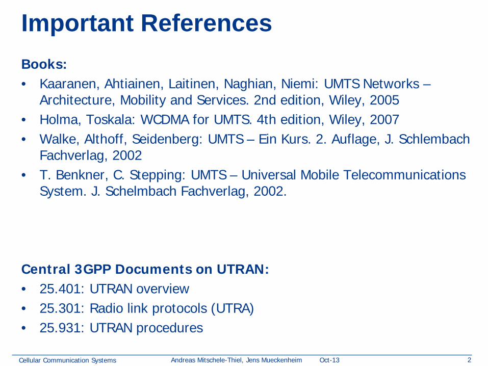
Architecture, Mobility and Services. 2nd edition, Wiley, 2005 • Holma, Toskala: WCDMA for UMTS. 4th edition, Wiley, 2007 • Walke, Althoff, Seidenberg: UMTS – Ein Kurs. 2. Auflage, J. Schlembach
Fachverlag, 2002 • T. Benkner, C. Stepping: UMTS – Universal Mobile Telecommunications
System. J. Schelmbach Fachverlag, 2002.
Central 3GPP Documents on UTRAN: • 25.401: UTRAN overview • 25.301: Radio link protocols (UTRA) • 25.931: UTRAN procedures
Cellular Communication Systems 3 Andreas Mitschele-Thiel, Jens Mueckenheim Oct-13
UTRAN Architecture
• Components and Interfaces • Macro Diversity • UTRAN Functions • Protocol Architecture • RRC connection and signaling connection • Access Stratum and Non Access Stratum
Cellular Communication Systems 4 Andreas Mitschele-Thiel, Jens Mueckenheim Oct-13
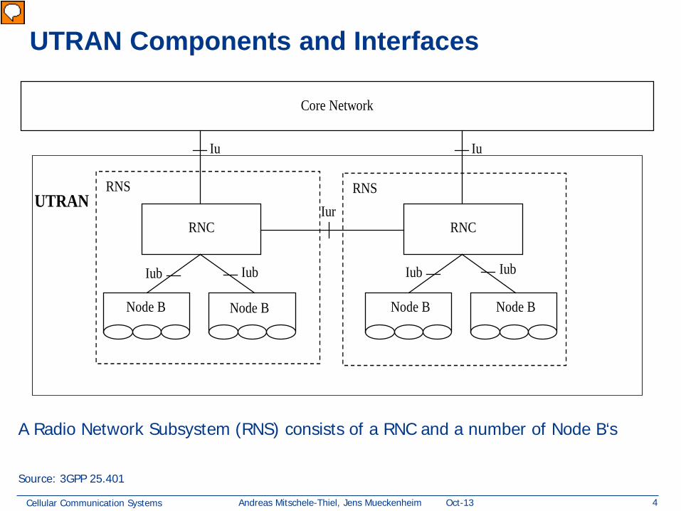
UTRAN Components and Interfaces
RNS
RNC
RNS
RNC
Core Network
Node B Node B Node B Node B
Iu Iu
Iur
Iub Iub Iub Iub
UTRAN
Source: 3GPP 25.401
A Radio Network Subsystem (RNS) consists of a RNC and a number of Node B‘s
Vorführender
Präsentationsnotizen
RNC may support combination/splitting of information streams SAS:Standalone A-GPS SMLC SMLC: Serving Mobile Location Centre
Cellular Communication Systems 5 Andreas Mitschele-Thiel, Jens Mueckenheim Oct-13
Macro Diversity: Serving and Drift RNS
Serving RNS (SRNS)
Core Network
Iu
Drift RNS (DRNS) Iur
UE
Cells
Source: 3GPP 25.401
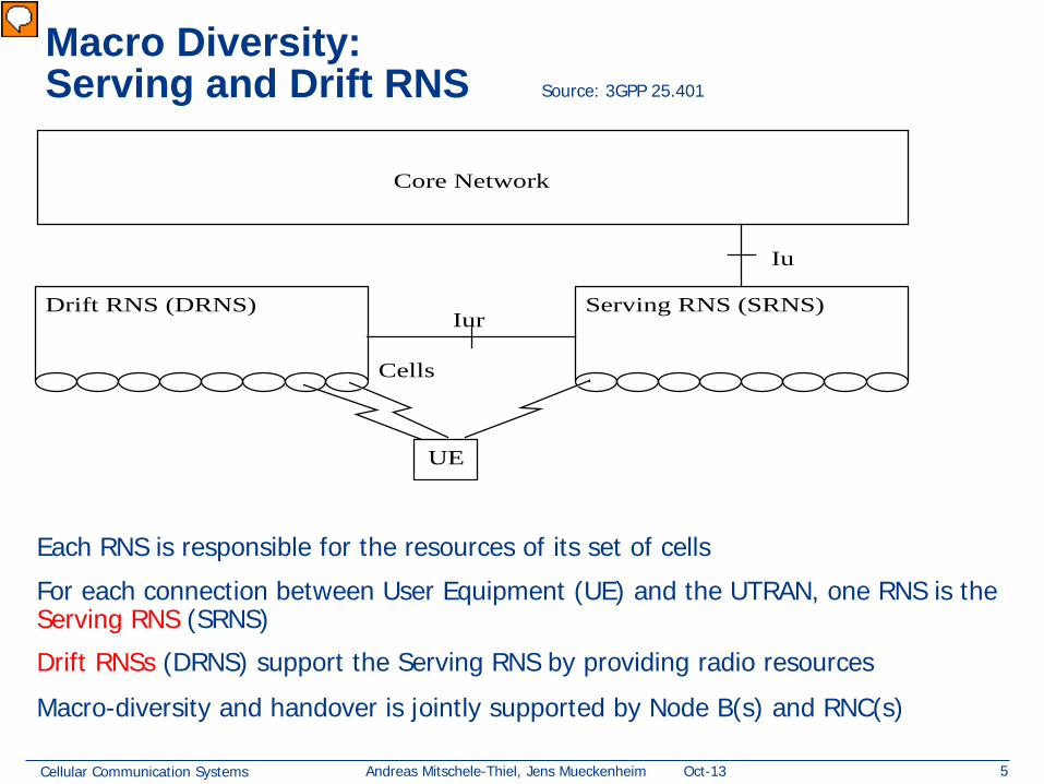
Each RNS is responsible for the resources of its set of cells For each connection between User Equipment (UE) and the UTRAN, one RNS is the Serving RNS (SRNS)
Drift RNSs (DRNS) support the Serving RNS by providing radio resources
Macro-diversity and handover is jointly supported by Node B(s) and RNC(s)
Vorführender
Präsentationsnotizen
Macro diversity: operation state in which UE simultaneously has radio links with two or more UTRAN access points (cells = sections) UTRAN access point: A conceptual point within the UTRAN performing radio transmission and reception. A UTRAN access point is associated with one specific cell (= sector), i.e. there exists one UTRAN access point for each cell. It is the UTRAN-side end point of a radio link. Radio link: A "radio link" is a logical association between single User Equipment and a single UTRAN access point. Its physical realisation comprises one or more radio bearer transmissions. Here we have 3 radio links in parallel!
Cellular Communication Systems 6 Andreas Mitschele-Thiel, Jens Mueckenheim Oct-13
Serving, Drift and Controlling RNC
RNS
RNC
RNS
RNC
Core Network
Node B Node B Node B Node B
Iu Iu
Iur
Iub Iub Iub Iub
UTRAN
UE
SRNC DRNC
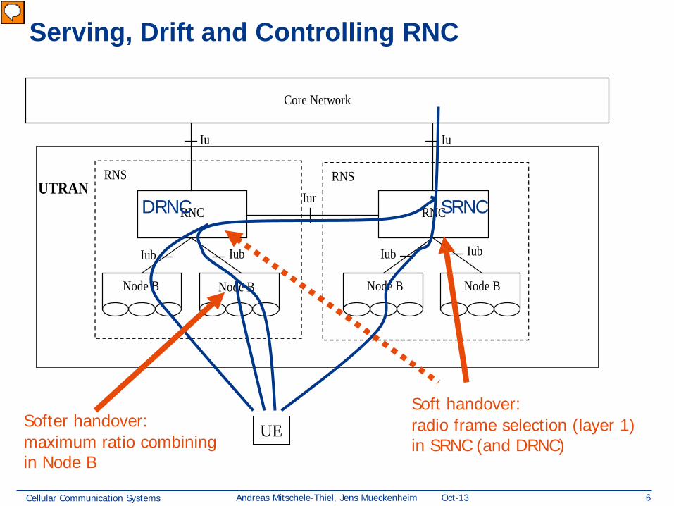
Softer handover: maximum ratio combining in Node B
Soft handover: radio frame selection (layer 1) in SRNC (and DRNC)
Vorführender
Präsentationsnotizen
How to deal with transmission errors – different choices: Lower L1: combination on analog level per bit (local repair at receiver) Higher L1 and L2: correction by forward error control per radio frame (local repair at receiver) L2: correction by retransmission of radio frame (~100 bíts) (distributed repair between sender and receiver) L4: correction by retransmission of TCP packet (distributed repair between sender and receiver)
Cellular Communication Systems 7 Andreas Mitschele-Thiel, Jens Mueckenheim Oct-13
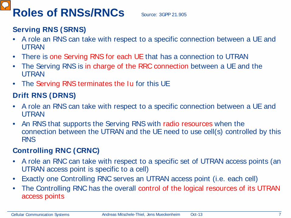
Roles of RNSs/RNCs Serving RNS (SRNS) • A role an RNS can take with respect to a specific connection between a UE and
UTRAN • There is one Serving RNS for each UE that has a connection to UTRAN • The Serving RNS is in charge of the RRC connection between a UE and the
UTRAN • The Serving RNS terminates the Iu for this UE
Drift RNS (DRNS) • A role an RNS can take with respect to a specific connection between a UE and
UTRAN • An RNS that supports the Serving RNS with radio resources when the
connection between the UTRAN and the UE need to use cell(s) controlled by this RNS
Controlling RNC (CRNC) • A role an RNC can take with respect to a specific set of UTRAN access points (an
UTRAN access point is specific to a cell) • Exactly one Controlling RNC serves an UTRAN access point (i.e. each cell) • The Controlling RNC has the overall control of the logical resources of its UTRAN
access points
Source: 3GPP 21.905
Vorführender
Präsentationsnotizen
Connection in this context means communication connection (control and possibly user plane), not a just physical radio link of which several may be present due to macro diversity (Mts) UTRAN access point; A conceptual point within the UTRAN performing radio transmission and reception. A UTRAN access point is associated with one specific cell, i.e. there exists one UTRAN access point for each cell. It is the UTRAN-side end point of a radio link. Radio link; A "radio link" is a logical association between single User Equipment and a single UTRAN access point. Its physical realization comprises one or more radio bearer transmissions
Cellular Communication Systems 8 Andreas Mitschele-Thiel, Jens Mueckenheim Oct-13
Distribution of Functions between RNCs
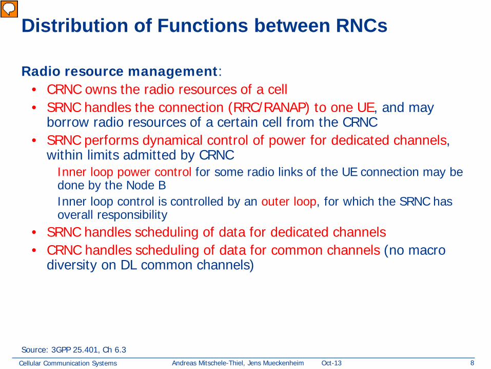
Radio resource management: • CRNC owns the radio resources of a cell • SRNC handles the connection (RRC/RANAP) to one UE, and may
borrow radio resources of a certain cell from the CRNC • SRNC performs dynamical control of power for dedicated channels,
within limits admitted by CRNC Inner loop power control for some radio links of the UE connection may be done by the Node B Inner loop control is controlled by an outer loop, for which the SRNC has overall responsibility
• SRNC handles scheduling of data for dedicated channels • CRNC handles scheduling of data for common channels (no macro
diversity on DL common channels)
Source: 3GPP 25.401, Ch 6.3
Vorführender
Präsentationsnotizen
Management of node-internal resources: Each UTRAN node is considered a network element on its own Knowledge about the equipment of a network element is kept within the network element itself and its management system The node itself always manages node-internal resources
Cellular Communication Systems 9 Andreas Mitschele-Thiel, Jens Mueckenheim Oct-13
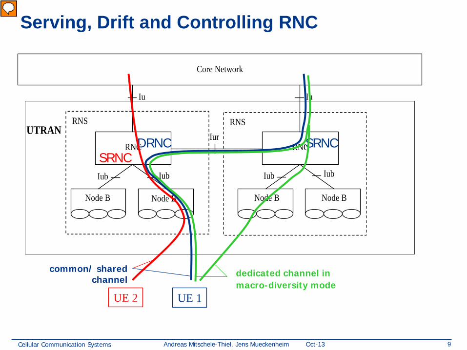
Serving, Drift and Controlling RNC
RNS
RNC
RNS
RNC
Core Network
Node B Node B Node B Node B
Iu Iu
Iur
Iub Iub Iub Iub
UTRAN
UE 1
SRNC DRNC
UE 2
common/ shared channel
SRNC
dedicated channel in macro-diversity mode
Vorführender
Präsentationsnotizen
two kind of transport channels provided at PHY SAP: shared and dedicated channels (DCH) shared: channel with shared code for multiple UEs that take shares in communication common: channel used for broadcast messages received by all/multiple UEs
Cellular Communication Systems 10 Andreas Mitschele-Thiel, Jens Mueckenheim Oct-13
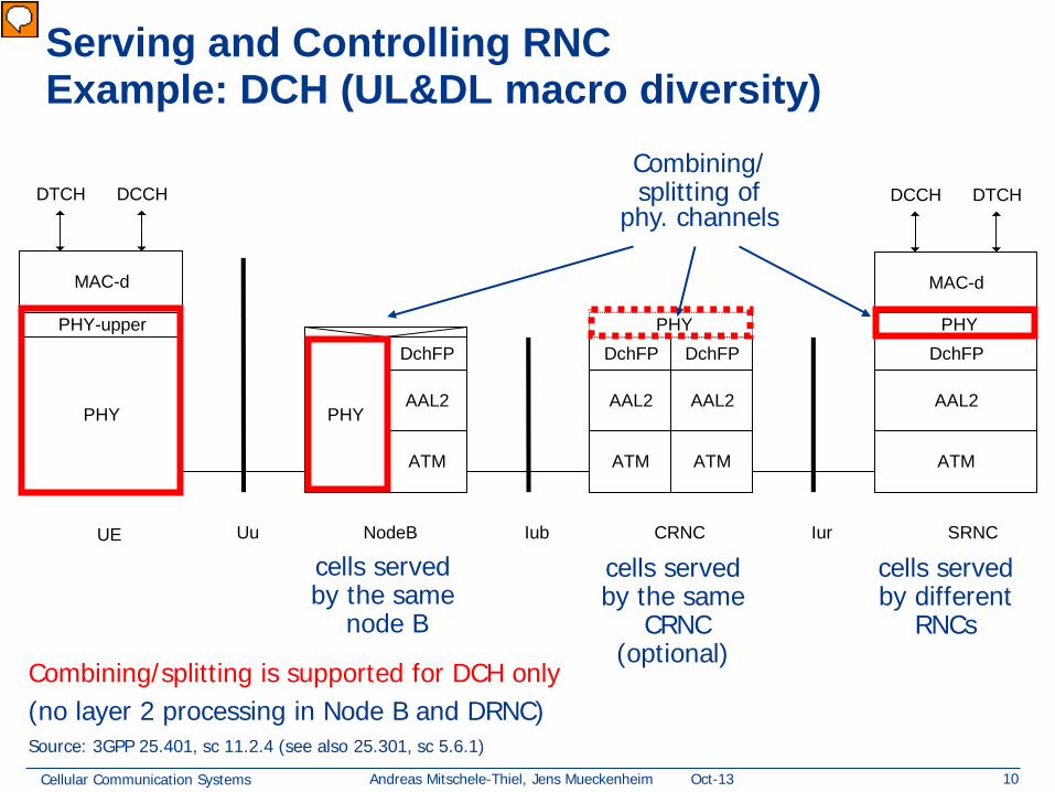
Serving and Controlling RNC Example: DCH (UL&DL macro diversity)
PHY PHY
ATM
DchFP
ATM
MAC-d
Iub UE NodeB CRNC Uu SRNC
ATM ATM
Iur
MAC-d
DCCH DTCH
DchFP PHY-upper PHY
AAL2 AAL2
DTCH DCCH
AAL2 AAL2
DchFP DchFP PHY
Source: 3GPP 25.401, sc 11.2.4 (see also 25.301, sc 5.6.1)
Combining/ splitting of
phy. channels
Combining/splitting is supported for DCH only (no layer 2 processing in Node B and DRNC)
cells served by the same
node B
cells served by the same
CRNC (optional)
cells served by different
RNCs
Vorführender
Präsentationsnotizen
Vgl mit 4-23: UTRAN als ein Block dargestellt Here: pathological case with SRNC and DRNC Bild mit radio links zu CRNC und SRNC zeigen! DCH is a transport channel, i.e provided at the PHY SAP Transport channel: focus on physical transport of data rather than focus on content (as with logical channels)
Cellular Communication Systems 11 Andreas Mitschele-Thiel, Jens Mueckenheim Oct-13
PHY PHY
ATM
FachFP
Iub UE NodeB CRNC Uu Iur SRNC
AAL2
ATM
FachFP
MAC-c/ sh
ATM ATM
MAC-d
DCCH DTCH
AAL2
MAC-c/ sh
MAC-d
DTCH DCCH
AAL2
FachFP
AAL2
FachFP
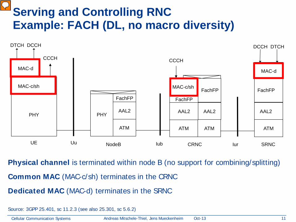
Serving and Controlling RNC Example: FACH (DL, no macro diversity)
Physical channel is terminated within node B (no support for combining/splitting)
Common MAC (MAC-c/sh) terminates in the CRNC
Dedicated MAC (MAC-d) terminates in the SRNC
Source: 3GPP 25.401, sc 11.2.3 (see also 25.301, sc 5.6.2)
CCCH CCCH
Vorführender
Präsentationsnotizen
FACH: Forward Access Channel, for replies to RACH with small volumes Why is CRNC involved here? only in case that the UE is connected to another RNC => Forget about the CRNC here
Cellular Communication Systems 12 Andreas Mitschele-Thiel, Jens Mueckenheim Oct-13
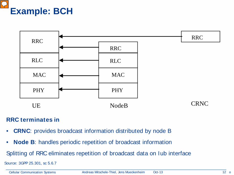
Example: BCH
UE NodeB
RLC
MAC
PHY
RLC
MAC
PHY
RRC RRC
RRC
CRNC
Source: 3GPP 25.301, sc 5.6.7
RRC terminates in
• CRNC: provides broadcast information distributed by node B
• Node B: handles periodic repetition of broadcast information
Splitting of RRC eliminates repetition of broadcast data on Iub interface
o
Vorführender
Präsentationsnotizen
5.6.7Protocol termination for transport channel of type BCH (copy from 25.301) System information on BCH (Broadcast Channel) can include information that is available only in Node B, and need to be updated very frequently (each 20-100 ms), such as uplink interference in the cell. Also, for the system information originating from the RNC, it is assumed that the updating of system information is at least one magnitude less (minutes) than the repetition frequency on the BCH (in the order of 1s). The system information originating from the CRNC should be sent transparently to Node B, which then handles the repetition. Protocol termination for the BCH shall therefore be distributed between the Node B and the CRNC, resulting in less signalling on Iub and lower processor load. Note that the RLC sublayer is transparent for this transport channel type.
Cellular Communication Systems 13 Andreas Mitschele-Thiel, Jens Mueckenheim Oct-13
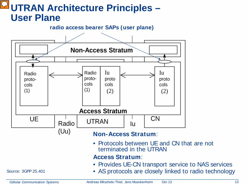
UTRAN Architecture Principles – User Plane
Source: 3GPP 25.401
Non-Access Stratum: • Protocols between UE and CN that are not
terminated in the UTRAN Access Stratum: • Provides UE-CN transport service to NAS services • AS protocols are closely linked to radio technology
UTRAN UE CN
Access Stratum
Non-Access Stratum
Radio (Uu)
Iu
Radio proto- cols (1)
Radio proto- cols (1)
Iu protocols (2)
Iu protocols (2)
radio access bearer SAPs (user plane)
Vorführender
Präsentationsnotizen
Non-Access Stratum; Protocols between UE and the core network that are not terminated in the UTRAN
Cellular Communication Systems 14 Andreas Mitschele-Thiel, Jens Mueckenheim Oct-13
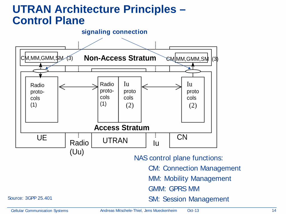
UTRAN Architecture Principles – Control Plane
UTRAN UE CN
Access Stratum
Non-Access Stratum
Radio (Uu)
Iu
Radio proto- cols (1)
Radio proto- cols (1)
Iu protocols (2)
Iu protocols (2)
CM,MM,GMM,SM (3)
CM,MM,GMM,SM (3)
Source: 3GPP 25.401
NAS control plane functions: CM: Connection Management MM: Mobility Management GMM: GPRS MM SM: Session Management
signaling connection
Cellular Communication Systems 15 Andreas Mitschele-Thiel, Jens Mueckenheim Oct-13
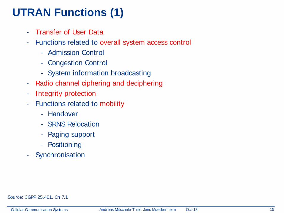
UTRAN Functions (1) - Transfer of User Data - Functions related to overall system access control
- Admission Control - Congestion Control - System information broadcasting
- Radio channel ciphering and deciphering - Integrity protection - Functions related to mobility
- Handover - SRNS Relocation - Paging support - Positioning
- Synchronisation
Source: 3GPP 25.401, Ch 7.1
Cellular Communication Systems 16 Andreas Mitschele-Thiel, Jens Mueckenheim Oct-13
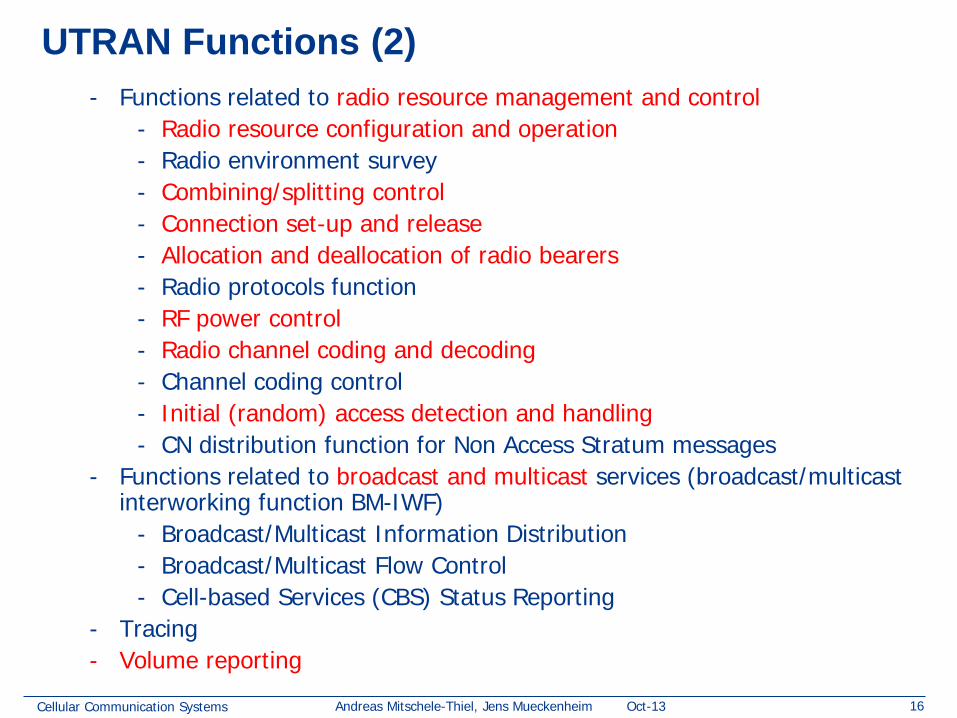
UTRAN Functions (2) - Functions related to radio resource management and control
- Radio resource configuration and operation - Radio environment survey - Combining/splitting control - Connection set-up and release - Allocation and deallocation of radio bearers - Radio protocols function - RF power control - Radio channel coding and decoding - Channel coding control - Initial (random) access detection and handling - CN distribution function for Non Access Stratum messages
- Functions related to broadcast and multicast services (broadcast/multicast interworking function BM-IWF)
- Broadcast/Multicast Information Distribution - Broadcast/Multicast Flow Control - Cell-based Services (CBS) Status Reporting
- Tracing - Volume reporting
Cellular Communication Systems 17 Andreas Mitschele-Thiel, Jens Mueckenheim Oct-13
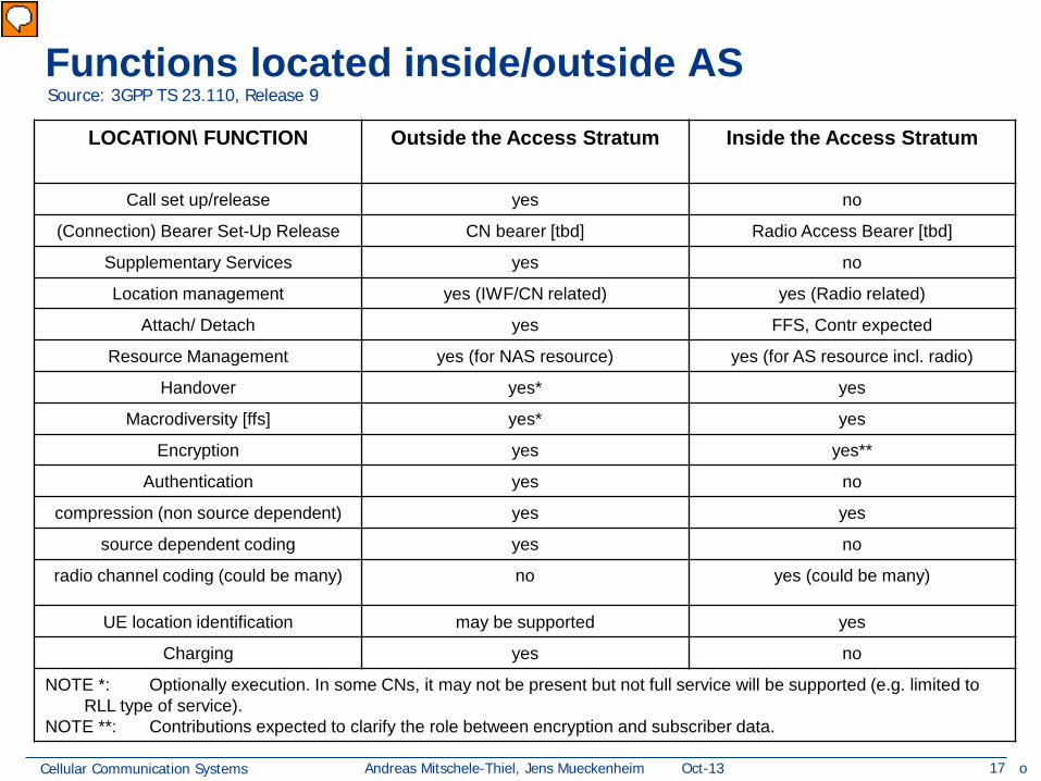
Functions located inside/outside AS Source: 3GPP TS 23.110, Release 9
LOCATION\ FUNCTION Outside the Access Stratum Inside the Access Stratum
Resource Management yes (for NAS resource) yes (for AS resource incl. radio)
Handover yes* yes
Macrodiversity [ffs] yes* yes
Encryption yes yes**
Authentication yes no
compression (non source dependent) yes yes
source dependent coding yes no
radio channel coding (could be many) no yes (could be many)
UE location identification may be supported yes
Charging yes no
NOTE *: Optionally execution. In some CNs, it may not be present but not full service will be supported (e.g. limited to RLL type of service).
NOTE **: Contributions expected to clarify the role between encryption and subscriber data.
o
Vorführender
Präsentationsnotizen
State: 2010, Release 9 (unchanged from earlier releases)
Cellular Communication Systems 18 Andreas Mitschele-Thiel, Jens Mueckenheim Oct-13
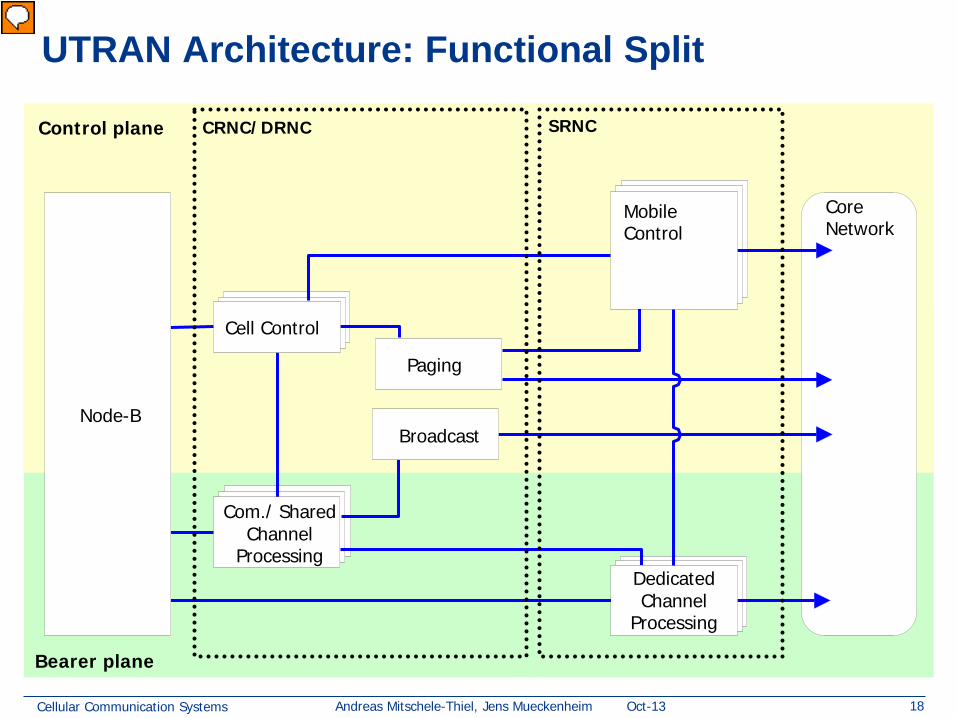
UTRAN Architecture: Functional Split
Control plane
Bearer plane
Core Network
Node-B
Paging
Com./ Shared Channel
Processing
Cell Control
Dedicated Channel
Processing
Mobile Control
Broadcast
CRNC/DRNC SRNC
Vorführender
Präsentationsnotizen
Compare shared with dedicated channel: IP/VoIP vs. plain old telefone service Yellow Post vs. Water supply (in residential area, not in disaster areas)
Cellular Communication Systems 19 Andreas Mitschele-Thiel, Jens Mueckenheim Oct-13
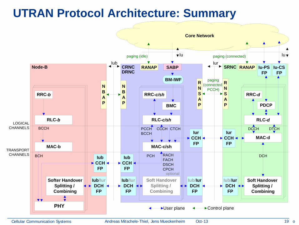
Core Network
User plane Control plane
Iub Iurpaging (connected)
paging(connected,
PCCH)
MAC-b
RLC-b
RRC-b
BCCH
BCH
PHY
Softer HandoverSplitting / Combining
NBAP
IubCCHFP
Node-B
Iub/IurDCHFP
Iu
Soft HandoverSplitting / Combining
optional
CTCHPCCHBCCH
NBAP
RNSAP
IurCCHFP
IubCCHFP
Iub/IurDCHFP
Iub/IurDCHFP
RANAPCRNC
paging (idle)
DRNCBM-IWF
PCH RACHFACHDSCHCPCH
CCCH
RLC-c/sh
MAC-c/sh
BMC
RRC-c/sh
SABP
Iu
MAC-d
DCH
DTCH
RLC-d
PDCP
RRC-d
Soft Handover Splitting / Combining
DCCH
SRNC
RNSAP
RANAP
IurCCHFP
Iub/IurDCHFP
Iu-CS FP
Iu-PS FP
LOGICAL CHANNELS
TRANSPORT CHANNELS
UTRAN Protocol Architecture: Summary
o
Cellular Communication Systems 20 Andreas Mitschele-Thiel, Jens Mueckenheim Oct-13
Wrap-up: Why is UTRAN so complicated?
Some answers:
• Limitation of radio resources and last-mile transport resources
• CDMA macro-diversity mode – Single RLC/MAC entity required for synchronous delivery of radio
frames over all SHO legs – Splitting/combining of radio frames (multicast)
• Tight handover requirements esp. for voice
– Need for proactive handover initiation requires interaction between radio layers
• Designed for maximum functionality and flexibility
– Overdimensioned from the viewpoint of a single application
Cellular Communication Systems 21 Andreas Mitschele-Thiel, Jens Mueckenheim Oct-13
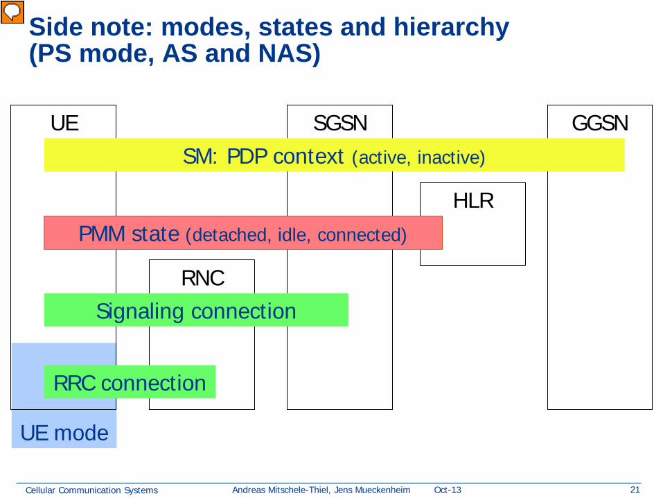
UE mode
HLR
GGSN
Side note: modes, states and hierarchy (PS mode, AS and NAS)
SGSN
RNC
UE
RRC connection
Signaling connection
PMM state (detached, idle, connected)
SM: PDP context (active, inactive)
Vorführender
Präsentationsnotizen
Problems we have to solve below PHY? manage sessions, manage mobility UTRAN: nur signaling connection und RRC connection relevant
Cellular Communication Systems 22 Andreas Mitschele-Thiel, Jens Mueckenheim Oct-13
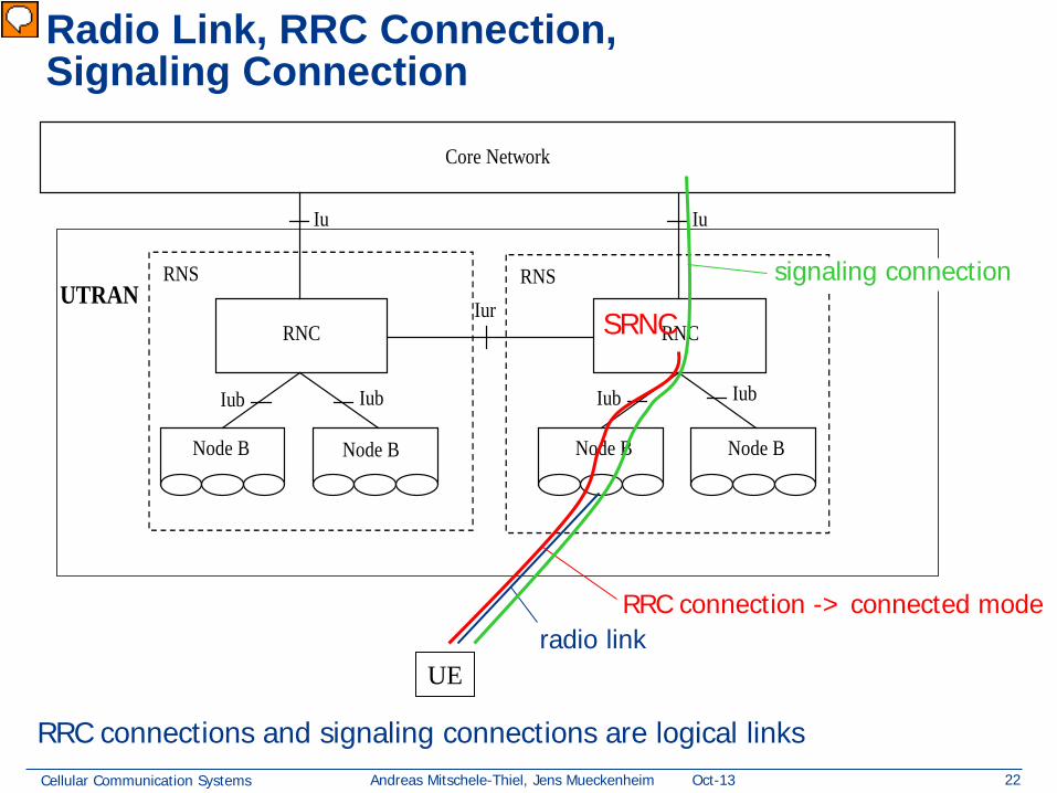
Radio Link, RRC Connection, Signaling Connection
RNS
RNC
RNS
RNC
Core Network
Node B Node B Node B Node B
Iu Iu
Iur
Iub Iub Iub Iub
UTRAN
UE radio link
RRC connection -> connected mode
signaling connection
SRNC
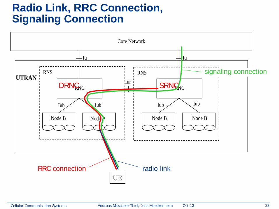
RRC connections and signaling connections are logical links
Vorführender
Präsentationsnotizen
compare to bearer-view in UMTS architecture picture (slide set 4) signaling connection: provice NAS a communication channel to the mobile RRC connection: provide UTRAN a communication channel to the mobile Radio link: phy/radio link to connect UE to RAN
Cellular Communication Systems 23 Andreas Mitschele-Thiel, Jens Mueckenheim Oct-13
Radio Link, RRC Connection, Signaling Connection
RNS
RNC
RNS
RNC
Core Network
Node B Node B Node B Node B
Iu Iu
Iur
Iub Iub Iub Iub
UTRAN
UE radio link
SRNC DRNC
RRC connection
signaling connection
Cellular Communication Systems 24 Andreas Mitschele-Thiel, Jens Mueckenheim Oct-13
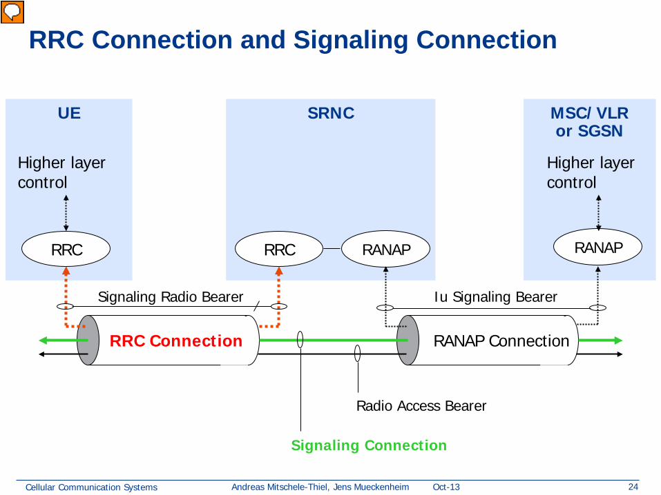
MSC/VLR or SGSN
SRNC UE
RRC Connection and Signaling Connection
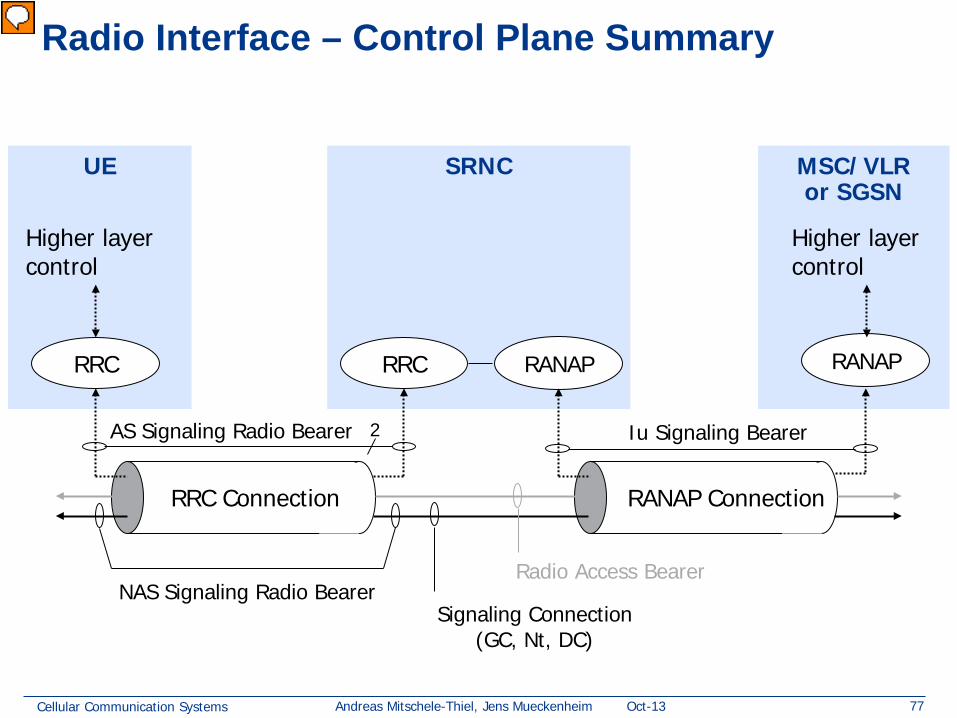
RRC Connection RANAP Connection
RRC RANAP RRC RANAP
Signaling Connection
Radio Access Bearer
Signaling Radio Bearer Iu Signaling Bearer
Higher layer control
Higher layer control
Vorführender
Präsentationsnotizen
RRC Connection; A point-to-point bi-directional connection between RRC peer entities on the UE and the UTRAN sides, respectively. An UE has either zero or one RRC connection This is not quite consistent with the figure!
Cellular Communication Systems 25 Andreas Mitschele-Thiel, Jens Mueckenheim Oct-13
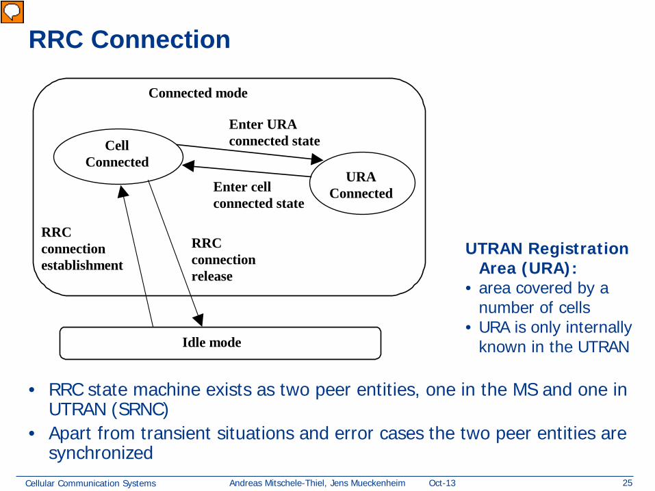
RRC Connection
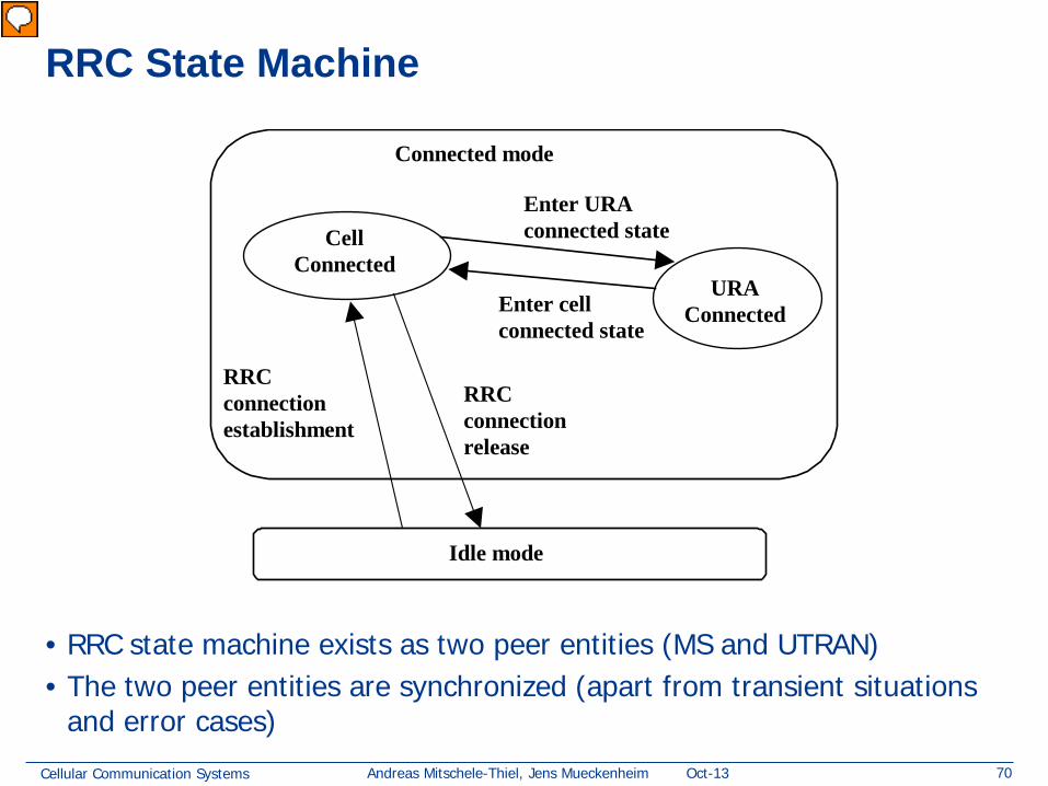
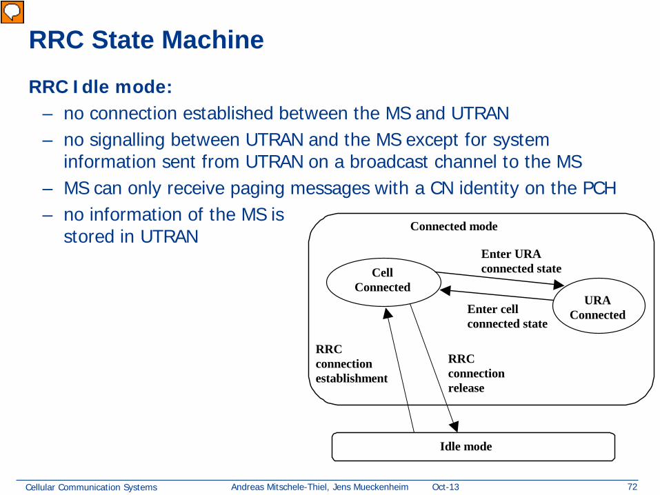
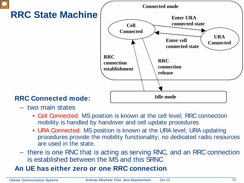
• RRC state machine exists as two peer entities, one in the MS and one in UTRAN (SRNC)
• Apart from transient situations and error cases the two peer entities are synchronized
Idle mode
CellConnected
RRCconnectionestablishment
URAConnected
RRCconnectionrelease
Enter URAconnected state
Enter cellconnected state
Connected mode
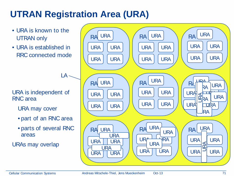
UTRAN Registration Area (URA):
• area covered by a number of cells
• URA is only internally known in the UTRAN
Vorführender
Präsentationsnotizen
The RRC state machine is a description model of how the MS and the UTRAN co-operate regarding RRC functionality. The RRC state describes the MS state in the UTRAN. This subclause contains a brief description of the RRC state machine, for more information see 3G TS 25.303.
Cellular Communication Systems 26 Andreas Mitschele-Thiel, Jens Mueckenheim Oct-13
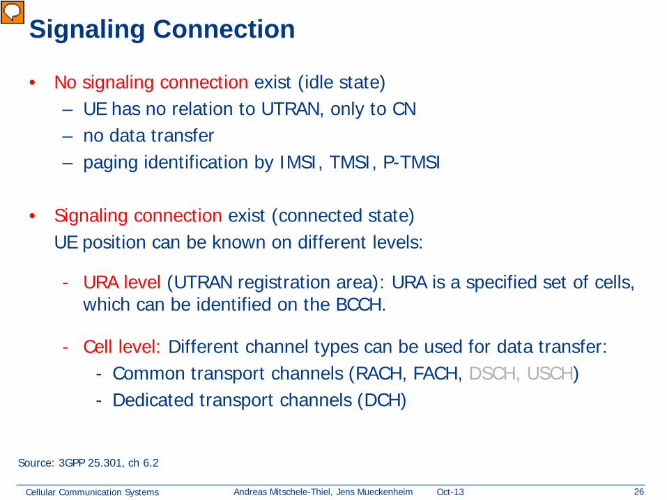
Signaling Connection
• No signaling connection exist (idle state) – UE has no relation to UTRAN, only to CN – no data transfer – paging identification by IMSI, TMSI, P-TMSI
• Signaling connection exist (connected state) UE position can be known on different levels:
- URA level (UTRAN registration area): URA is a specified set of cells, which can be identified on the BCCH.
- Cell level: Different channel types can be used for data transfer:
- Common transport channels (RACH, FACH, DSCH, USCH) - Dedicated transport channels (DCH)
Source: 3GPP 25.301, ch 6.2
Vorführender
Präsentationsnotizen
I am not sure if the meaning of signaling connection in the context of ch 6.2 is the same as the definition given in 25.990
Cellular Communication Systems 27 Andreas Mitschele-Thiel, Jens Mueckenheim Oct-13
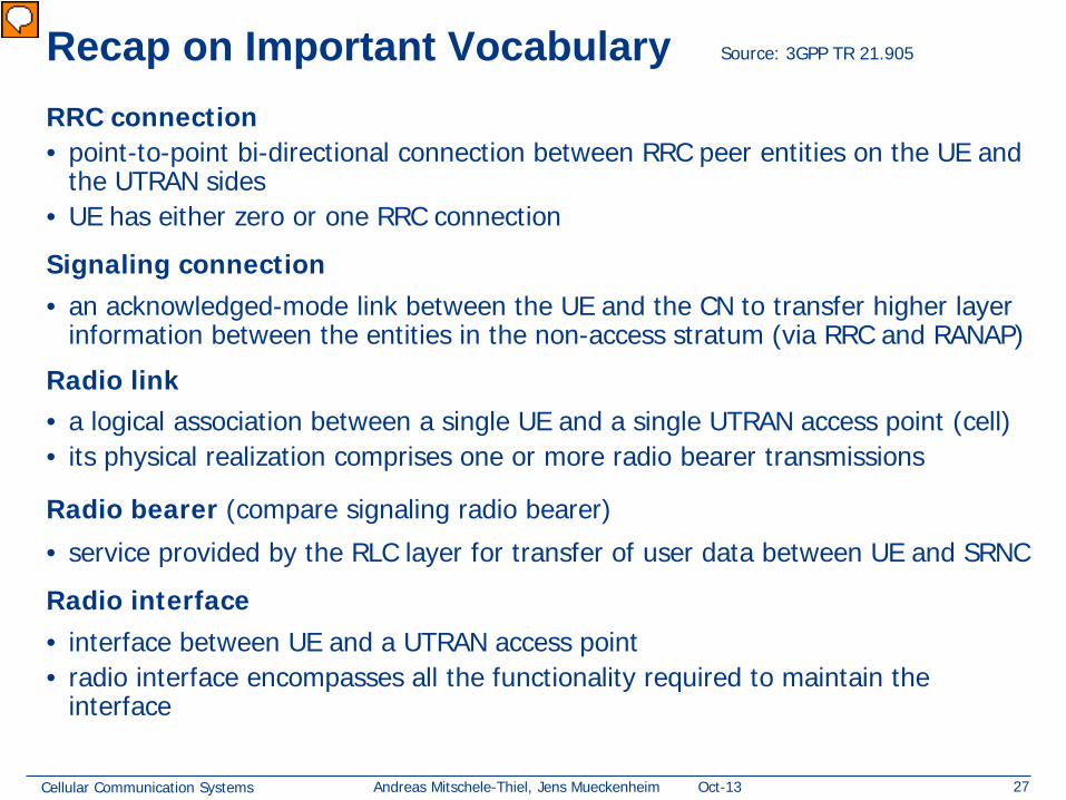
Recap on Important Vocabulary RRC connection • point-to-point bi-directional connection between RRC peer entities on the UE and
the UTRAN sides • UE has either zero or one RRC connection
Signaling connection • an acknowledged-mode link between the UE and the CN to transfer higher layer
information between the entities in the non-access stratum (via RRC and RANAP)
Radio link • a logical association between a single UE and a single UTRAN access point (cell) • its physical realization comprises one or more radio bearer transmissions
Radio bearer (compare signaling radio bearer)
• service provided by the RLC layer for transfer of user data between UE and SRNC
Radio interface • interface between UE and a UTRAN access point • radio interface encompasses all the functionality required to maintain the
interface
Source: 3GPP TR 21.905
Vorführender
Präsentationsnotizen
Radio access bearer; The service that the access stratum provides to the non-access stratum for transfer of user data between UE and CN. Signaling link; Provides an acknowledged-mode link layer to transfer the MS-UTRAN signaling messages as well as MS - Core Network signaling messages (using the signaling connection)
Cellular Communication Systems 28 Andreas Mitschele-Thiel, Jens Mueckenheim Oct-13
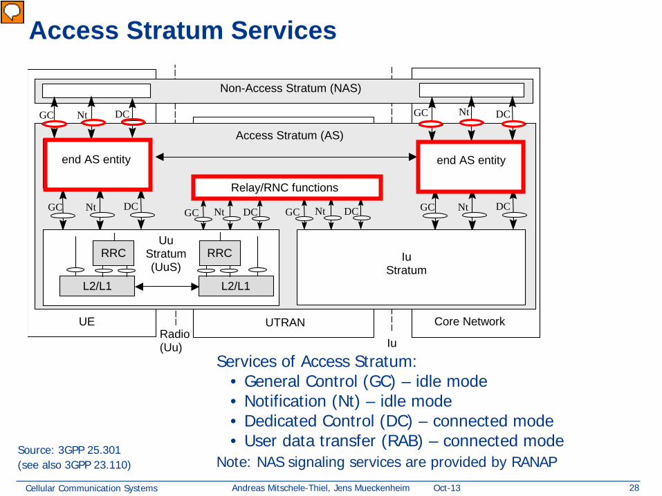
Access Stratum Services
DC Nt GC
UTRAN UE Core Network
Access Stratum (AS)
Non-Access Stratum (NAS)
Radio (Uu) Iu
DC Nt GC
DC Nt GC DC Nt GC DC Nt GC DC Nt GC
end AS entity end AS entity
Relay/RNC functions
Uu Stratum (UuS)
Iu Stratum
L2/L1
RRC
L2/L1
RRC
Source: 3GPP 25.301 (see also 3GPP 23.110)
Services of Access Stratum: • General Control (GC) – idle mode • Notification (Nt) – idle mode • Dedicated Control (DC) – connected mode • User data transfer (RAB) – connected mode
Note: NAS signaling services are provided by RANAP
Vorführender
Präsentationsnotizen
SAP des AS sind wie Briefkästen für Transport verschiedener Arten von Meldungen
Cellular Communication Systems 29 Andreas Mitschele-Thiel, Jens Mueckenheim Oct-13
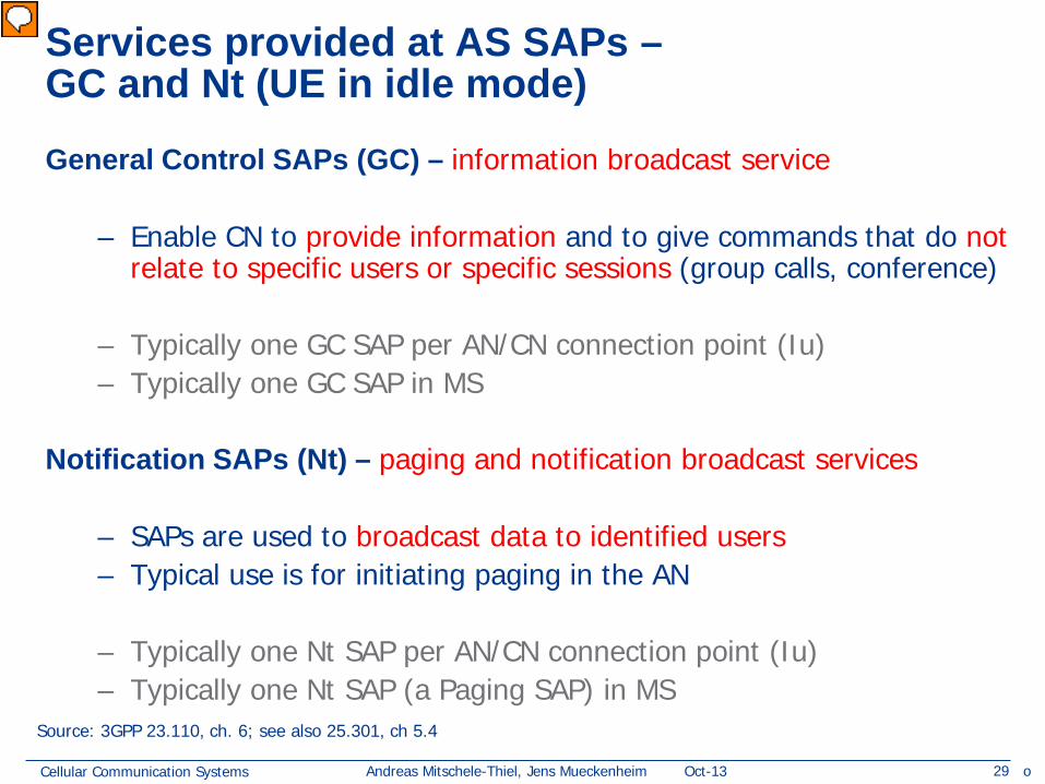
Services provided at AS SAPs – GC and Nt (UE in idle mode)
General Control SAPs (GC) – information broadcast service – Enable CN to provide information and to give commands that do not
relate to specific users or specific sessions (group calls, conference)
– Typically one GC SAP per AN/CN connection point (Iu) – Typically one GC SAP in MS
Notification SAPs (Nt) – paging and notification broadcast services
– SAPs are used to broadcast data to identified users – Typical use is for initiating paging in the AN
– Typically one Nt SAP per AN/CN connection point (Iu) – Typically one Nt SAP (a Paging SAP) in MS
Source: 3GPP 23.110, ch. 6; see also 25.301, ch 5.4
o
Vorführender
Präsentationsnotizen
5.4.1Uu Stratum services (copy from 25.301) 5.4.1.1General Control The GC SAP provides an information broadcast service. This service broadcasts information to all UEs in a certain geographical area. The basic requirements from such service are: -It should be possible to broadcast non-access stratum information in a certain geographical area. -The information is transferred on an unacknowledged mode link. Unacknowledged mode means that the delivery of the broadcast information can not be guaranteed (typically no retransmission scheme is used). It seems reasonable to use an unacknowledged mode link since the information is broadcast to a lot of UEs and since broadcast information often is repeated periodically. -It should be possible to do repeated transmissions of the broadcast information (how it is repeated is controlled by the non-access stratum). The point where the UE received the broadcast information should be included, when the access stratum delivers broadcast information to the non-access stratum. 5.4.1.2Notification The Nt SAP provides paging and notification broadcast services. The paging service sends information to a specific UE(s). The information is broadcast in a certain geographical area but addressed to a specific UE(s). The basic requirements from such service are: -It should be possible to broadcast paging information to a number of UEs in a certain geographical area. -The information is transferred on an unacknowledged mode link. It is assumed that the protocol entities in non-access stratum handle any kind of retransmission of paging information. The notification broadcast service broadcasts information to all UEs in a certain geographical. The basic requirements from this service are typically the same as for the information broadcast service of the GC SAP: -It should be possible to broadcast notification information in a certain geographical area. -The information is transferred on an unacknowledged mode link. 5.4.1.3Dedicated Control The DC SAP provides services for establishment/release of a connection and transfer of messages using this connection. It should also be possible to transfer a message during the establishment phase. The basic requirements from the establishment/release services are: -It should be possible to establish connections (both point and group connections). -It should be possible to transfer an initial message during the connection establishment phase. This message transfer has the same requirements as the information transfer service. -It should be possible to release connections. The information transfer service sends a message using the earlier established connection. According to [1] it is possible to specify the quality of service requirements for each message. A finite number of quality of service classes will be specified in [1], but currently no class has been specified. In order to get an idea of the basic requirements, the CC and MM protocols in GSM are used as a reference. A GSM based core network is chosen since it is one main option for UMTS. Considering the existing GSM specification of CC and MM the basic requirements from the information transfer service provided by the 'Duplication avoidance' function are (these are some of the services provided by the combination of a duplication layer, RR and the data link layer in GSM): -In-sequence transfer of messages�Messages are delivered to the NAS on the receiver side exactly in the order they have been submitted by the NAS on the sending side, without loss or duplication, except possibly for the loss of last messages in case of connection abortion. -Priority handling�If SMS messages should be transported through the control plane it should be possible to give higher priority to signalling messages. The CC and MM protocols also expect other services, which can not be supported by the current primitives of the DC SAP, e.g. indication of radio link failure. The information transfer service is provided by a combination of the services provided by the data link layer, RNC and the 'Duplication avoidance' function.
Cellular Communication Systems 30 Andreas Mitschele-Thiel, Jens Mueckenheim Oct-13
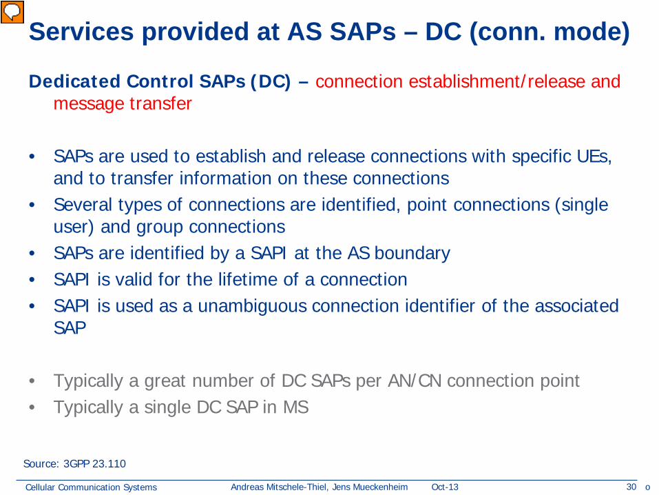
Services provided at AS SAPs – DC (conn. mode)
Dedicated Control SAPs (DC) – connection establishment/release and message transfer
• SAPs are used to establish and release connections with specific UEs, and to transfer information on these connections
• Several types of connections are identified, point connections (single user) and group connections
• SAPs are identified by a SAPI at the AS boundary • SAPI is valid for the lifetime of a connection • SAPI is used as a unambiguous connection identifier of the associated
SAP • Typically a great number of DC SAPs per AN/CN connection point • Typically a single DC SAP in MS
Source: 3GPP 23.110
o
Vorführender
Präsentationsnotizen
NOTE 1:On the UE side, an open issue is whether simultaneous services from distinct ANs can be provided to an MS. Settling this issue may lead to a different model, for instance with the possibility to have several Dedicated Control SAPs, one per AN with which an active context exists. Another issue, visible when analysing Point-to-Multipoint services in GSM, is the SAP modelling for those PTM services. NOTE 2:The model is limited in this version to the cases where all the activity between a User Equipment and the infrastructure pertains to the same subscriber. Extension to cases with several subscriber sharing a User Equipment requires further study. 5.4.1.3Dedicated Control (copy from 25.301) The DC SAP provides services for establishment/release of a connection and transfer of messages using this connection. It should also be possible to transfer a message during the establishment phase. The basic requirements from the establishment/release services are: -It should be possible to establish connections (both point and group connections). -It should be possible to transfer an initial message during the connection establishment phase. This message transfer has the same requirements as the information transfer service. -It should be possible to release connections. The information transfer service sends a message using the earlier established connection. According to [1] it is possible to specify the quality of service requirements for each message. A finite number of quality of service classes will be specified in [1], but currently no class has been specified. In order to get an idea of the basic requirements, the CC and MM protocols in GSM are used as a reference. A GSM based core network is chosen since it is one main option for UMTS. Considering the existing GSM specification of CC and MM the basic requirements from the information transfer service provided by the 'Duplication avoidance' function are (these are some of the services provided by the combination of a duplication layer, RR and the data link layer in GSM): -In-sequence transfer of messages�Messages are delivered to the NAS on the receiver side exactly in the order they have been submitted by the NAS on the sending side, without loss or duplication, except possibly for the loss of last messages in case of connection abortion. -Priority handling�If SMS messages should be transported through the control plane it should be possible to give higher priority to signalling messages. The CC and MM protocols also expect other services, which can not be supported by the current primitives of the DC SAP, e.g. indication of radio link failure. The information transfer service is provided by a combination of the services provided by the data link layer, RNC and the 'Duplication avoidance' function.
Cellular Communication Systems 31 Andreas Mitschele-Thiel, Jens Mueckenheim Oct-13
Radio Interface Protocols UMTS Terrestrial Radio Access (UTRA)
• Air interface protocol architecture
• Layer 1, 2 and 3 protocols
• Mapping between logical, transport and physical channels
Cellular Communication Systems 32 Andreas Mitschele-Thiel, Jens Mueckenheim Oct-13
Cellular Communication Systems 35 Andreas Mitschele-Thiel, Jens Mueckenheim Oct-13
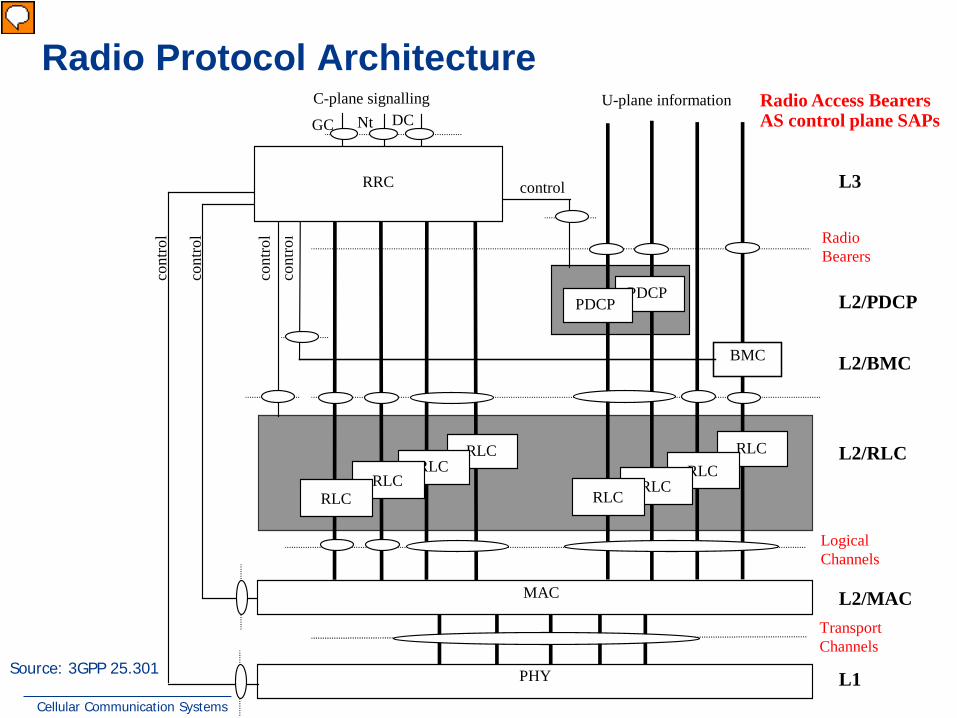
Source: 3GPP 25.301
Radio Access Bearers AS control plane SAPs
Radio Protocol Architecture
L3
cont
rol
cont
rol
cont
rol
cont
rol
Logical Channels
Transport Channels
C-plane signalling U-plane information
PHY
L2/MAC
L1
RLC
DC Nt GC
L2/RLC
MAC
RLC RLC
RLC RLC
RLC RLC
RLC
BMC L2/BMC
control
PDCP PDCP L2/PDCP
Radio Bearers
RRC
Vorführender
Präsentationsnotizen
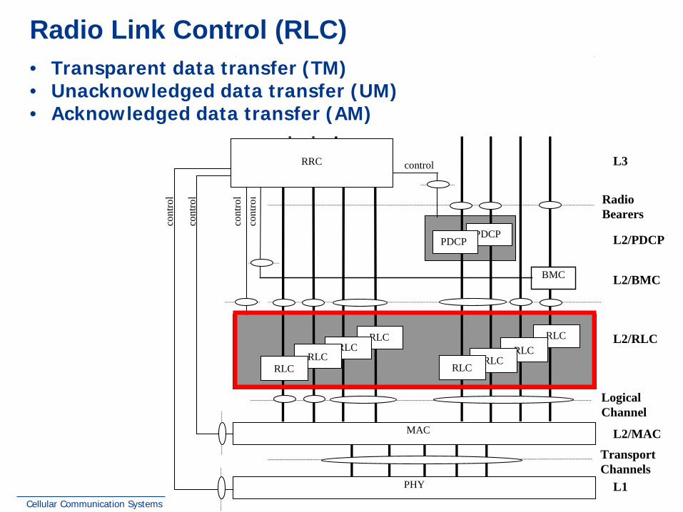
The radio protocol architecture in the UTRAN is layered. At the top are the RRC and the traffic; below that is the link layer, which is split into the RLC and the MAC (the BMC and PDCP layers are ignored in this discussion); and at the bottom is the Physical layer. The layers have different functionality, which can be summarised as follows: RRC: A great many functions, including setup, maintenance and teardown of connections to the mobile (UE). Also controls broadcast and paging, measurement reporting, outer loop power setpoints and it interprets requested Quality of Service (QoS) RLC: Functions related to data transfer, such as segmentation and reassembly, in-sequence delivery, error-correction and flow control. Three modes, transparent, acknowledged and unacknowledged, are provided. MAC: This readies transport blocks for most efficient transfer over the air. The functions include: scheduling, multiplexing, channel type switching, UE identification (on common channels) and transport format selection on a frame-by-frame basis. PHY: This provides low-level functionality such as macro-diversity combining, channel coding, rate matching, channel multiplexing, multi-code distribution, rake finger control, fast power control and others.
Cellular Communication Systems 36 Andreas Mitschele-Thiel, Jens Mueckenheim Oct-13
L3
cont
rol
cont
rol
cont
rol
cont
rol
Logical Channel
Transport Channels
C-plane signalling U-plane information
PHY
L2/MAC
L1
RLC
DC Nt GC
L2/RLC
MAC
RLC RLC
RLC RLC
RLC RLC
RLC
Duplication avoidance
UuS boundary
BMC L2/BMC
control
PDCP PDCP L2/PDCP
DC Nt GC
Radio Bearers
RRC
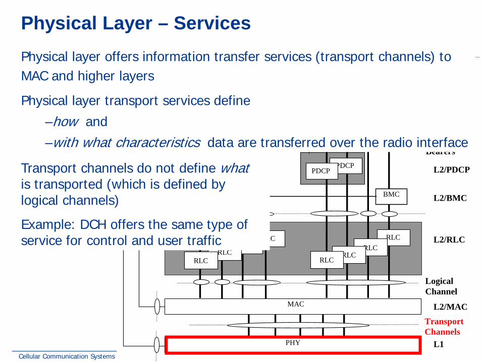
Radio Access Bearers AS control plane SAPs Physical Layer – Services
Transport channels do not define what is transported (which is defined by logical channels)
Example: DCH offers the same type of service for control and user traffic
Physical layer offers information transfer services (transport channels) to MAC and higher layers Physical layer transport services define
–how and –with what characteristics data are transferred over the radio interface
Cellular Communication Systems 37 Andreas Mitschele-Thiel, Jens Mueckenheim Oct-13
Radio Access Bearers AS control plane SAPs
L3
cont
rol
cont
rol
cont
rol
cont
rol
Logical Channel
Transport Channels
C-plane signalling U-plane information
PHY
L2/MAC
L1
RLC
DC Nt GC
L2/RLC
MAC
RLC RLC
RLC RLC
RLC RLC
RLC
Duplication avoidance
UuS boundary
BMC L2/BMC
control
PDCP PDCP L2/PDCP
DC Nt GC
Radio Bearers
RRC
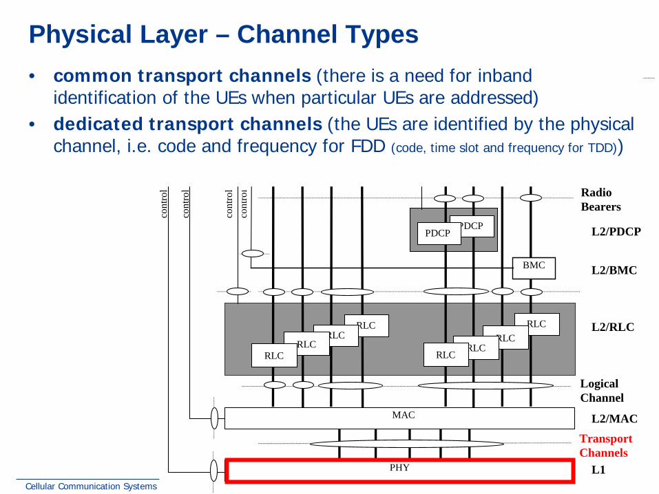
Physical Layer – Channel Types • common transport channels (there is a need for inband
identification of the UEs when particular UEs are addressed) • dedicated transport channels (the UEs are identified by the physical
channel, i.e. code and frequency for FDD (code, time slot and frequency for TDD))
Cellular Communication Systems 38 Andreas Mitschele-Thiel, Jens Mueckenheim Oct-13
Physical Layer – Common Transport Channels (1)
Random Access Channel (RACH) • Contention based uplink channel used for transmission of relatively
small amounts of data, e.g. for initial access or non-real-time dedicated control or traffic data
Forward Access Channel (FACH) • Common downlink channel for relatively small amount of data • no closed-loop power control
Downlink Shared Channel (DSCH) – TDD only • Downlink channel shared by several UEs carrying dedicated control or
traffic data Uplink Shared Channel (USCH) – TDD only
• Uplink channel shared by several UEs carrying dedicated control or traffic data
Cellular Communication Systems 39 Andreas Mitschele-Thiel, Jens Mueckenheim Oct-13
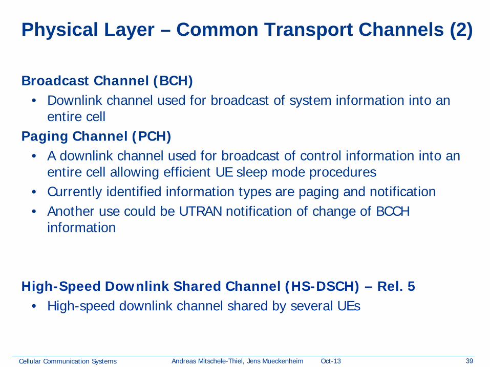
Physical Layer – Common Transport Channels (2)
Broadcast Channel (BCH) • Downlink channel used for broadcast of system information into an
entire cell Paging Channel (PCH)
• A downlink channel used for broadcast of control information into an entire cell allowing efficient UE sleep mode procedures
• Currently identified information types are paging and notification • Another use could be UTRAN notification of change of BCCH
• High-speed downlink channel shared by several UEs
Cellular Communication Systems 40 Andreas Mitschele-Thiel, Jens Mueckenheim Oct-13
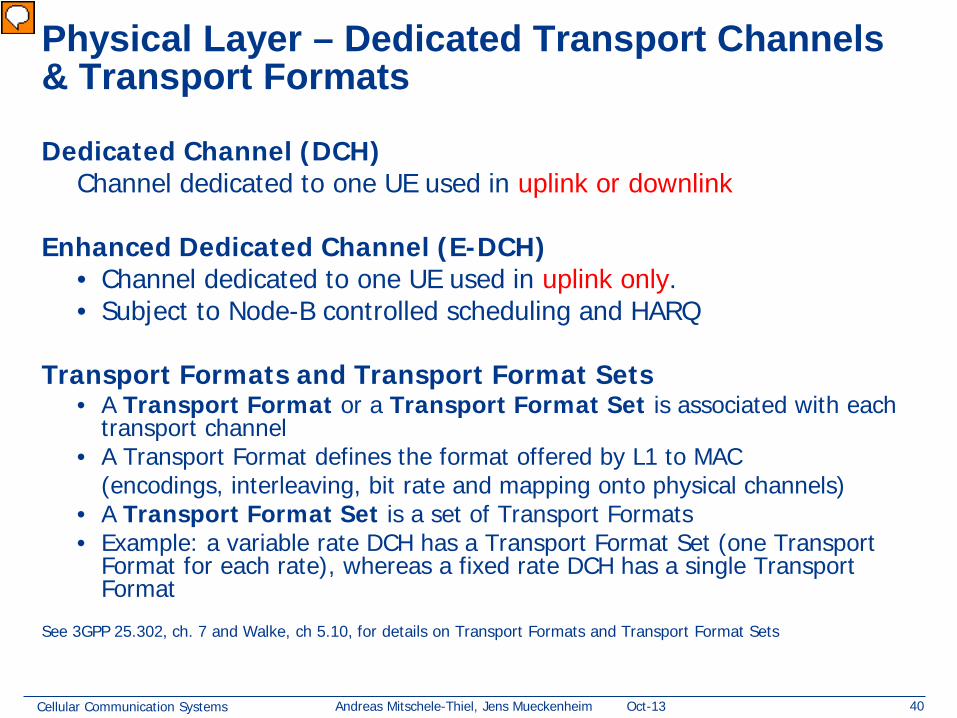
Physical Layer – Dedicated Transport Channels & Transport Formats
Dedicated Channel (DCH) Channel dedicated to one UE used in uplink or downlink
Enhanced Dedicated Channel (E-DCH) • Channel dedicated to one UE used in uplink only. • Subject to Node-B controlled scheduling and HARQ
Transport Formats and Transport Format Sets • A Transport Format or a Transport Format Set is associated with each
transport channel • A Transport Format defines the format offered by L1 to MAC (encodings, interleaving, bit rate and mapping onto physical channels) • A Transport Format Set is a set of Transport Formats • Example: a variable rate DCH has a Transport Format Set (one Transport
Format for each rate), whereas a fixed rate DCH has a single Transport Format
See 3GPP 25.302, ch. 7 and Walke, ch 5.10, for details on Transport Formats and Transport Format Sets
Vorführender
Präsentationsnotizen
Details on transport format and transport format set are described in 25.302, ch 7
Cellular Communication Systems 41 Andreas Mitschele-Thiel, Jens Mueckenheim Oct-13
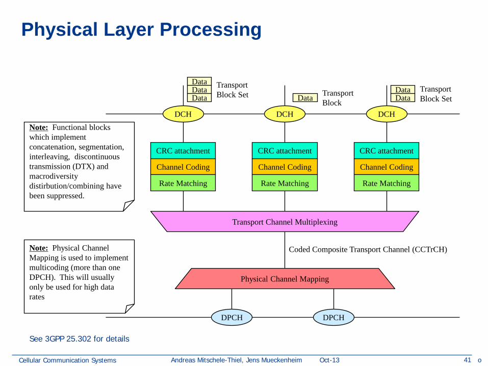
Physical Layer Processing
DCH DCH DCH
DPCH DPCH
CRC attachment
Channel Coding
Rate Matching
CRC attachment
Channel Coding
Rate Matching
CRC attachment
Channel Coding
Rate Matching
Transport Channel Multiplexing
Physical Channel Mapping
Coded Composite Transport Channel (CCTrCH)
Data Data Data Data
Data Data
Transport Block Set
Transport Block Set
Transport Block
Note: Physical Channel Mapping is used to implement multicoding (more than one DPCH). This will usually only be used for high data rates
Note: Functional blocks which implement concatenation, segmentation, interleaving, discontinuous transmission (DTX) and macrodiversity distirbution/combining have been suppressed.
See 3GPP 25.302 for details
o
Cellular Communication Systems 43 Andreas Mitschele-Thiel, Jens Mueckenheim Oct-13
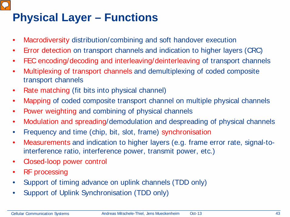
Physical Layer – Functions
• Macrodiversity distribution/combining and soft handover execution • Error detection on transport channels and indication to higher layers (CRC) • FEC encoding/decoding and interleaving/deinterleaving of transport channels • Multiplexing of transport channels and demultiplexing of coded composite
transport channels • Rate matching (fit bits into physical channel) • Mapping of coded composite transport channel on multiple physical channels • Power weighting and combining of physical channels • Modulation and spreading/demodulation and despreading of physical channels • Frequency and time (chip, bit, slot, frame) synchronisation • Measurements and indication to higher layers (e.g. frame error rate, signal-to-
interference ratio, interference power, transmit power, etc.) • Closed-loop power control • RF processing • Support of timing advance on uplink channels (TDD only) • Support of Uplink Synchronisation (TDD only)
Vorführender
Präsentationsnotizen
Rate Matching: due to FEC, etc. block size may not match the required size which requires deletion or addition of bits FER: Frame error rate
Cellular Communication Systems 44 Andreas Mitschele-Thiel, Jens Mueckenheim Oct-13
L3
cont
rol
cont
rol
cont
rol
cont
rol
Logical Channel
Transport Channels
C-plane signalling U-plane information
PHY
L2/MAC
L1
RLC
DC Nt GC
L2/RLC
MAC
RLC RLC
RLC RLC
RLC RLC
RLC
Duplication avoidance
UuS boundary
BMC L2/BMC
control
PDCP PDCP L2/PDCP
DC Nt GC
Radio Bearers
RRC
Radio Access Bearers AS control plane SAPs Medium Access Control (MAC) – Services
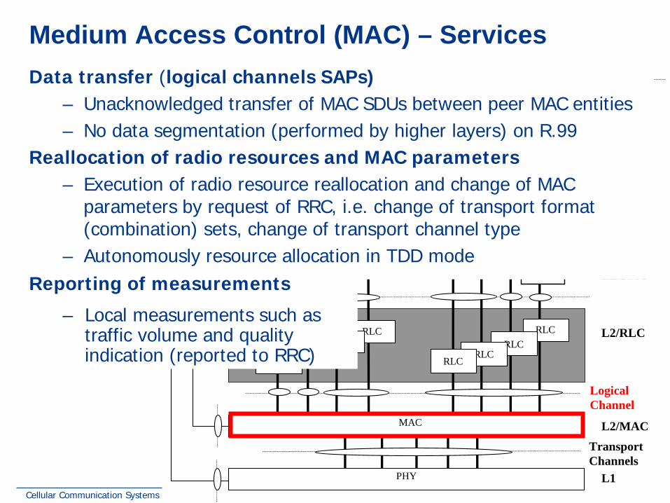
Data transfer (logical channels SAPs) – Unacknowledged transfer of MAC SDUs between peer MAC entities – No data segmentation (performed by higher layers) on R.99
Reallocation of radio resources and MAC parameters – Execution of radio resource reallocation and change of MAC
parameters by request of RRC, i.e. change of transport format (combination) sets, change of transport channel type
– Autonomously resource allocation in TDD mode Reporting of measurements
– Local measurements such as traffic volume and quality indication (reported to RRC)
Cellular Communication Systems 45 Andreas Mitschele-Thiel, Jens Mueckenheim Oct-13
MAC – Logical Channels
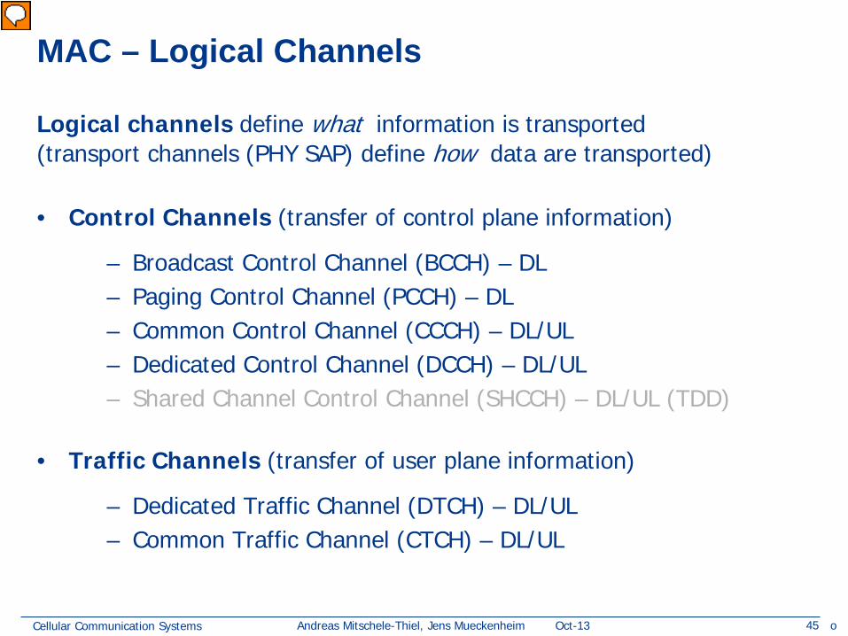
• Control Channels (transfer of control plane information) – Broadcast Control Channel (BCCH) – DL – Paging Control Channel (PCCH) – DL – Common Control Channel (CCCH) – DL/UL – Dedicated Control Channel (DCCH) – DL/UL – Shared Channel Control Channel (SHCCH) – DL/UL (TDD)
• Traffic Channels (transfer of user plane information) – Dedicated Traffic Channel (DTCH) – DL/UL – Common Traffic Channel (CTCH) – DL/UL
Logical channels define what information is transported (transport channels (PHY SAP) define how data are transported)
o
Vorführender
Präsentationsnotizen
Control Channels Control channels are used for transfer of control plane information only. Broadcast Control Channel (BCCH) A downlink channel for broadcasting system control information. Paging Control Channel (PCCH) A downlink channel that transfers paging information. This channel is used when the network does not know the location cell of the UE, or, the UE is in the cell connected state (utilising UE sleep mode procedures). Common Control Channel (CCCH) Bi-directional channel for transmitting control information between network and UEs. This channel is commonly used by the UEs having no RRC connection with the network and by the UEs using common transport channels when accessing a new cell after cell reselection. Dedicated Control Channel (DCCH) A point-to-point bi-directional channel that transmits dedicated control information between a UE and the network. This channel is established through RRC connection setup procedure. Shared Channel Control Channel (SHCCH) Bi-directional channel that transmits control information for uplink and downlink shared channels between network and UEs. This channel is for TDD only. Traffic Channels Traffic channels are used for the transfer of user plane information only. Dedicated Traffic Channel (DTCH) A Dedicated Traffic Channel (DTCH) is a point-to-point channel, dedicated to one UE, for the transfer of user information. A DTCH can exist in both uplink and downlink. Common Traffic Channel (CTCH) A point-to-multipoint unidirectional channel for transfer of dedicated user information for all or a group of specified UEs.
Cellular Communication Systems 46 Andreas Mitschele-Thiel, Jens Mueckenheim Oct-13
MAC – Functions (1)
PHY PHY
ATM
DschFP
IubUE NodeB CRNCUu Iur SRNC
AAL2
ATM
DschFP
MAC-c/sh
ATM ATM
MAC-d
DCCH DTCH
AAL2
MAC-c/sh
MAC-d
DTCH DCCH
AAL2
DschFP
AAL2
DschFP
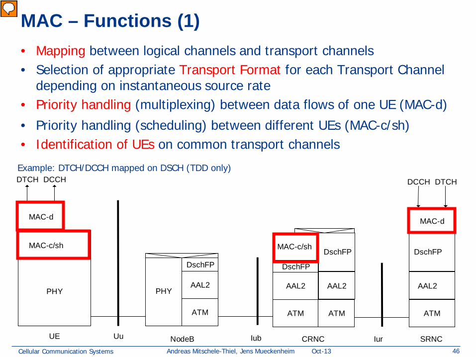
• Mapping between logical channels and transport channels • Selection of appropriate Transport Format for each Transport Channel
depending on instantaneous source rate • Priority handling (multiplexing) between data flows of one UE (MAC-d)
• Priority handling (scheduling) between different UEs (MAC-c/sh) • Identification of UEs on common transport channels
Example: DTCH/DCCH mapped on DSCH (TDD only)
Vorführender
Präsentationsnotizen
5.3.1.2MAC functions (copy from 25.301-4.1.0) The functions of MAC include: -Mapping between logical channels and transport channels. The MAC is responsible for mapping of logical channel(s) onto the appropriate transport channel(s). -Selection of appropriate Transport Format for each Transport Channel depending on instantaneous source rate. Given the Transport Format Combination Set assigned by RRC, MAC selects the appropriate transport format within an assigned transport format set for each active transport channel depending on source rate. The control of transport formats ensures efficient use of transport channels. -Priority handling between data flows of one UE. When selecting between the Transport Format Combinations in the given Transport Format Combination Set, priorities of the data flows to be mapped onto the corresponding Transport Channels can be taken into account. Priorities are e.g. given by attributes of Radio Bearer services and RLC buffer status. The priority handling is achieved by selecting a Transport Format Combination for which high priority data is mapped onto L1 with a "high bit rate" Transport Format, at the same time letting lower priority data be mapped with a "low bit rate" (could be zero bit rate) Transport Format. Transport format selection may also take into account transmit power indication from Layer 1. -Priority handling between UEs by means of dynamic scheduling. In order to utilise the spectrum resources efficiently for bursty transfer, a dynamic scheduling function may be applied. MAC realises priority handling on common and shared transport channels. Note that for dedicated transport channels, the equivalent of the dynamic scheduling function is implicitly included as part of the reconfiguration function of the RRC sublayer. NOTE:In the TDD mode the data to be transported are represented in terms of sets of resource units. -Identification of UEs on common transport channels. When a particular UE is addressed on a common downlink channel, or when a UE is using the RACH, there is a need for inband identification of the UE. Since the MAC layer handles the access to, and multiplexing onto, the transport channels, the identification functionality is naturally also placed in MAC. -Multiplexing/demultiplexing of upper layer PDUs into/from transport blocks delivered to/from the physical layer on common transport channels. MAC should support service multiplexing for common transport channels, since the physical layer does not support multiplexing of these channels. -Multiplexing/demultiplexing of upper layer PDUs into/from transport block sets delivered to/from the physical layer on dedicated transport channels. The MAC allows service multiplexing for dedicated transport channels. This function can be utilised when several upper layer services (e.g. RLC instances) can be mapped efficiently on the same transport channel. In this case the identification of multiplexing is contained in the MAC protocol control information. -Traffic volume measurement. Measurement of traffic volume on logical channels and reporting to RRC. Based on the reported traffic volume information, RRC performs transport channel switching decisions. -Transport Channel type switching. Execution of the switching between common and dedicated transport channels based on a switching decision derived by RRC. -Ciphering. This function prevents unauthorised acquisition of data. Ciphering is performed in the MAC layer for transparent RLC mode. Details of the security architecture are specified in [15]. -Access Service Class selection for RACH and CPCH transmission. The RACH resources (i.e. access slots and preamble signatures for FDD, timeslot and channelisation code for TDD) and CPCH resources (i.e. access slots and preamble signatures for FDD only) may be divided between different Access Service Classes in order to provide different priorities of RACH and CPCH usage. In addition it is possible for more than one ASC or for all ASCs to be assigned to the same access slot/signature space. Each access service class will also have a set of back-off parameters associated with it, some or all of which may be broadcast by the network. The MAC function applies the appropriate back-off and indicates to the PHY layer the RACH and CPCH partition associated to a given MAC PDU transfer.
Cellular Communication Systems 47 Andreas Mitschele-Thiel, Jens Mueckenheim Oct-13
MAC – Functions (2)
PHY PHY
ATM
DschFP
IubUE NodeB CRNCUu Iur SRNC
AAL2
ATM
DschFP
MAC-c/sh
ATM ATM
MAC-d
DCCH DTCH
AAL2
MAC-c/sh
MAC-d
DTCH DCCH
AAL2
DschFP
AAL2
DschFP
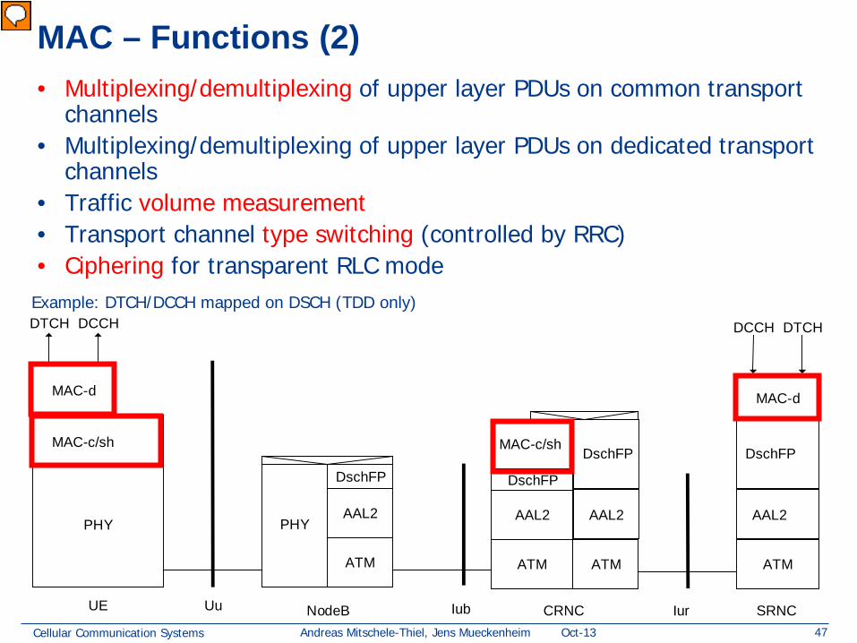
• Multiplexing/demultiplexing of upper layer PDUs on common transport channels
• Multiplexing/demultiplexing of upper layer PDUs on dedicated transport channels
• Traffic volume measurement • Transport channel type switching (controlled by RRC) • Ciphering for transparent RLC mode
Example: DTCH/DCCH mapped on DSCH (TDD only)
Vorführender
Präsentationsnotizen
5.3.1.2MAC functions (copy from 25.301-4.1.0) The functions of MAC include: -Mapping between logical channels and transport channels. The MAC is responsible for mapping of logical channel(s) onto the appropriate transport channel(s). -Selection of appropriate Transport Format for each Transport Channel depending on instantaneous source rate. Given the Transport Format Combination Set assigned by RRC, MAC selects the appropriate transport format within an assigned transport format set for each active transport channel depending on source rate. The control of transport formats ensures efficient use of transport channels. -Priority handling between data flows of one UE. When selecting between the Transport Format Combinations in the given Transport Format Combination Set, priorities of the data flows to be mapped onto the corresponding Transport Channels can be taken into account. Priorities are e.g. given by attributes of Radio Bearer services and RLC buffer status. The priority handling is achieved by selecting a Transport Format Combination for which high priority data is mapped onto L1 with a "high bit rate" Transport Format, at the same time letting lower priority data be mapped with a "low bit rate" (could be zero bit rate) Transport Format. Transport format selection may also take into account transmit power indication from Layer 1. -Priority handling between UEs by means of dynamic scheduling. In order to utilise the spectrum resources efficiently for bursty transfer, a dynamic scheduling function may be applied. MAC realises priority handling on common and shared transport channels. Note that for dedicated transport channels, the equivalent of the dynamic scheduling function is implicitly included as part of the reconfiguration function of the RRC sublayer. NOTE:In the TDD mode the data to be transported are represented in terms of sets of resource units. -Identification of UEs on common transport channels. When a particular UE is addressed on a common downlink channel, or when a UE is using the RACH, there is a need for inband identification of the UE. Since the MAC layer handles the access to, and multiplexing onto, the transport channels, the identification functionality is naturally also placed in MAC. -Multiplexing/demultiplexing of upper layer PDUs into/from transport blocks delivered to/from the physical layer on common transport channels. MAC should support service multiplexing for common transport channels, since the physical layer does not support multiplexing of these channels. -Multiplexing/demultiplexing of upper layer PDUs into/from transport block sets delivered to/from the physical layer on dedicated transport channels. The MAC allows service multiplexing for dedicated transport channels. This function can be utilised when several upper layer services (e.g. RLC instances) can be mapped efficiently on the same transport channel. In this case the identification of multiplexing is contained in the MAC protocol control information. -Traffic volume measurement. Measurement of traffic volume on logical channels and reporting to RRC. Based on the reported traffic volume information, RRC performs transport channel switching decisions. -Transport Channel type switching. Execution of the switching between common and dedicated transport channels based on a switching decision derived by RRC. -Ciphering. This function prevents unauthorised acquisition of data. Ciphering is performed in the MAC layer for transparent RLC mode. Details of the security architecture are specified in [15]. -Access Service Class selection for RACH and CPCH transmission. The RACH resources (i.e. access slots and preamble signatures for FDD, timeslot and channelisation code for TDD) and CPCH resources (i.e. access slots and preamble signatures for FDD only) may be divided between different Access Service Classes in order to provide different priorities of RACH and CPCH usage. In addition it is possible for more than one ASC or for all ASCs to be assigned to the same access slot/signature space. Each access service class will also have a set of back-off parameters associated with it, some or all of which may be broadcast by the network. The MAC function applies the appropriate back-off and indicates to the PHY layer the RACH and CPCH partition associated to a given MAC PDU transfer.
Cellular Communication Systems 48 Andreas Mitschele-Thiel, Jens Mueckenheim Oct-13
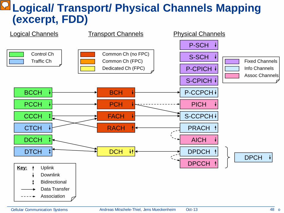
Logical Channels Transport Channels Physical Channels
DPCH Key: Uplink
Downlink Bidirectional Data Transfer Association
Control Ch Traffic Ch
Common Ch (no FPC) Common Ch (FPC) Dedicated Ch (FPC) Info Channels
Assoc Channels
Fixed Channels
o
Vorführender
Präsentationsnotizen
Transport channels are mapped to physical channels as shown in the slide. There are many physical channels which do not carry higher-layer traffic; some are associated with traffic-carrying channels, while others are necessary for cell discovery by the UE and channel estimation. As indicated previously, multiple transport channels can be multiplexed onto a single physical channel, or conversely, one transport channel can be transferred over multiple physical channels (multicode). PCH and FACH can be multiplexed onto the same S-CCPCH or can each be transferred over separate S-CCPCHs. Associated channels are used as follows: PICH indicates in an efficient manner that information for a mobile will shortly be transferred on the PCH transport channel; AICH indicates that an access preamble has been received, and that the UE can stop ramping up its power, or (for PCPCH) that a collision detect preamble has been received and resolved. DPCCH carries power control information for associated channels as well as TFC indication for DPDCH, and pilot and feedback information. This DCH can be of very low bandwidth compared to the shared channel, and may well carry the DCCH. Notes: Figure deschribes a subset of the possible mappings only! See 25.301, sc. 5.6 or following slides for the complete list of possible mappings. FPC denotes Fast Power Control
Cellular Communication Systems 51 Andreas Mitschele-Thiel, Jens Mueckenheim Oct-13
L3
cont
rol
cont
rol
cont
rol
cont
rol
Logical Channel
Transport Channels
C-plane signalling U-plane information
PHY
L2/MAC
L1
RLC
DC Nt GC
L2/RLC
MAC
RLC RLC
RLC RLC
RLC RLC
RLC
Duplication avoidance
UuS boundary
BMC L2/BMC
control
PDCP PDCP L2/PDCP
DC Nt GC
Radio Bearers
RRC
• Transparent data transfer (TM) • Unacknowledged data transfer (UM) • Acknowledged data transfer (AM)
Radio Link Control (RLC)
Cellular Communication Systems 52 Andreas Mitschele-Thiel, Jens Mueckenheim Oct-13
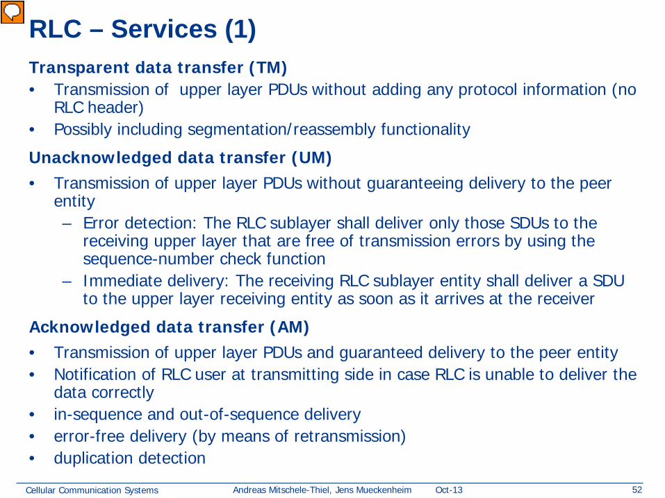
RLC – Services (1) Transparent data transfer (TM) • Transmission of upper layer PDUs without adding any protocol information (no
RLC header) • Possibly including segmentation/reassembly functionality
Unacknowledged data transfer (UM) • Transmission of upper layer PDUs without guaranteeing delivery to the peer
entity – Error detection: The RLC sublayer shall deliver only those SDUs to the
receiving upper layer that are free of transmission errors by using the sequence-number check function
– Immediate delivery: The receiving RLC sublayer entity shall deliver a SDU to the upper layer receiving entity as soon as it arrives at the receiver
Acknowledged data transfer (AM) • Transmission of upper layer PDUs and guaranteed delivery to the peer entity • Notification of RLC user at transmitting side in case RLC is unable to deliver the
data correctly • in-sequence and out-of-sequence delivery • error-free delivery (by means of retransmission) • duplication detection
Vorführender
Präsentationsnotizen
5.3.2.1Services provided to the upper layer (copy from 25.301-4.1.0) -Transparent data transfer. This service transmits upper layer PDUs without adding any protocol information, possibly including segmentation/reassembly functionality. -Unacknowledged data transfer. This service transmits upper layer PDUs without guaranteeing delivery to the peer entity. The unacknowledged data transfer mode has the following characteristics: -Detection of erroneous data: The RLC sublayer shall deliver only those SDUs to the receiving upper layer that are free of transmission errors by using the sequence-number check function. -Immediate delivery: The receiving RLC sublayer entity shall deliver a SDU to the upper layer receiving entity as soon as it arrives at the receiver. -Acknowledged data transfer. This service transmits upper layer PDUs and guarantees delivery to the peer entity. In case RLC is unable to deliver the data correctly, the user of RLC at the transmitting side is notified. For this service, both in-sequence and out-of-sequence delivery are supported. In many cases a upper layer protocol can restore the order of its PDUs. As long as the out-of-sequence properties of the lower layer are known and controlled (i.e. the upper layer protocol will not immediately request retransmission of a missing PDU) allowing out-of-sequence delivery can save memory space in the receiving RLC. The acknowledged data transfer mode has the following characteristics: -Error-free delivery: Error-free delivery is ensured by means of retransmission. The receiving RLC entity delivers only error-free SDUs to the upper layer. -Unique delivery: The RLC sublayer shall deliver each SDU only once to the receiving upper layer using duplication detection function. -In-sequence delivery: RLC sublayer shall provide support for in-order delivery of SDUs, i.e., RLC sublayer should deliver SDUs to the receiving upper layer entity in the same order as the transmitting upper layer entity submits them to the RLC sublayer. -Out-of-sequence delivery: Alternatively to in-sequence delivery, it shall also be possible to allow that the receiving RLC entity delivers SDUs to upper layer in different order than submitted to RLC sublayer at the transmitting side.
Cellular Communication Systems 53 Andreas Mitschele-Thiel, Jens Mueckenheim Oct-13
RLC – Services (2) Maintenance of QoS as defined by upper layers • retransmission protocol shall be configurable by layer 3 to provide
different levels of QoS
Notification of unrecoverable errors
• RLC notifies the upper layer of errors that cannot be resolved by RLC itself by normal exception handling procedures
There is a single RLC connection per Radio Bearer
Vorführender
Präsentationsnotizen
5.3.2.1Services provided to the upper layer (copy from 25.301-4.1.0) -Maintenance of QoS as defined by upper layers. The retransmission protocol shall be configurable by layer 3 to provide different levels of QoS. This can be controlled. -Notification of unrecoverable errors. RLC notifies the upper layer of errors that cannot be resolved by RLC itself by normal exception handling procedures, e.g. by adjusting the maximum number of retransmissions according to delay requirements. There is a single RLC connection per Radio Bearer.
Cellular Communication Systems 54 Andreas Mitschele-Thiel, Jens Mueckenheim Oct-13
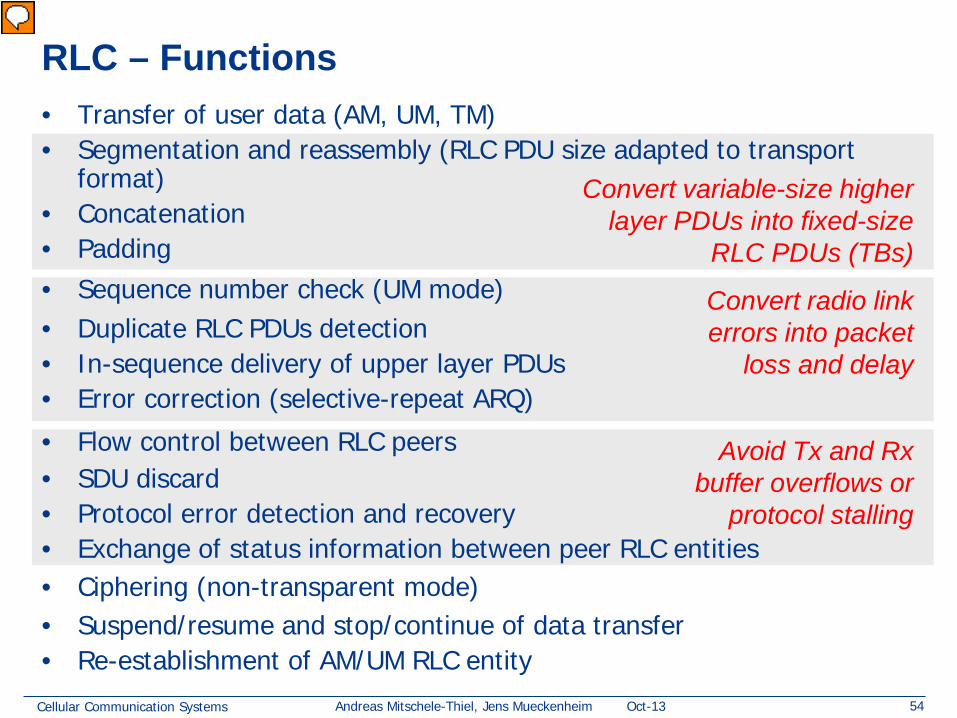
RLC – Functions • Transfer of user data (AM, UM, TM) • Segmentation and reassembly (RLC PDU size adapted to transport
• Flow control between RLC peers • SDU discard • Protocol error detection and recovery • Exchange of status information between peer RLC entities • Ciphering (non-transparent mode) • Suspend/resume and stop/continue of data transfer • Re-establishment of AM/UM RLC entity
Convert variable-size higher layer PDUs into fixed-size
RLC PDUs (TBs)
Convert radio link errors into packet
loss and delay
Avoid Tx and Rx buffer overflows or
protocol stalling
Vorführender
Präsentationsnotizen
5.3.2.2RLC Functions (copy from 25.301-4.1.0) -Segmentation and reassembly. This function performs segmentation/reassembly of variable-length upper layer PDUs into/from smaller RLC PDUs. The RLC PDU size is adjustable to the actual set of transport formats. -Concatenation. If the contents of an RLC SDU cannot be carried by one RLC PDU, the first segment of the next RLC SDU may be put into the RLC PDU in concatenation with the last segment of the previous RLC SDU. -Padding. When concatenation is not applicable and the remaining data to be transmitted does not fill an entire RLC PDU of given size, the remainder of the data field shall be filled with padding bits. -Transfer of user data. This function is used for conveyance of data between users of RLC services. RLC supports acknowledged, unacknowledged and transparent data transfer. QoS setting controls transfer of user data. -Error correction. This function provides error correction by retransmission (e.g. Selective Repeat, Go Back N, or a Stop-and-Wait ARQ) in acknowledged data transfer mode. -In-sequence delivery of upper layer PDUs. This function preserves the order of higher layer PDUs that were submitted for transfer by RLC using the acknowledged data transfer service. If this function is not used, out-of-sequence delivery is provided. -Duplicate Detection. This function detects duplicated received RLC PDUs and ensures that the resultant upper layer PDU is delivered only once to the upper layer. -Flow control. This function allows an RLC receiver to control the rate at which the peer RLC transmitting entity may send information. -Sequence number check. This function is used in unacknowledged mode and guarantees the integrity of reassembled PDUs and provides a mechanism for the detection of corrupted RLC SDUs through checking sequence number in RLC PDUs when they are reassembled into a RLC SDU. A corrupted RLC SDU will be discarded. -Protocol error detection and recovery. This function detects and recovers from errors in the operation of the RLC protocol. -Ciphering. This function prevents unauthorised acquisition of data. Ciphering is performed in RLC layer for non-transparent RLC mode. Details of the security architecture are specified in [15]. -Polling. This function is used when an RLC transmitter requests a status report of an RLC receiver. -Status transmission. An RLC receiver uses this function to transmit status reports to a RLC transmitter in order to inform about which PDUs that have been received and not received. -SDU discard. This function allows an RLC transmitter to discharge RLC SDU from the buffer. -Estimated PDU Counter (EPC) mechanism. This function is used for scheduling the retransmission of status reports in the receiver side. -Suspend/resume function. Suspension and resumption of data transfer. -Stop/continue function. Stop and continue of data transfer. -Re-establishment function. Re-establish an acknowledged or unacknowledged mode RLC entity.
Cellular Communication Systems 55 Andreas Mitschele-Thiel, Jens Mueckenheim Oct-13
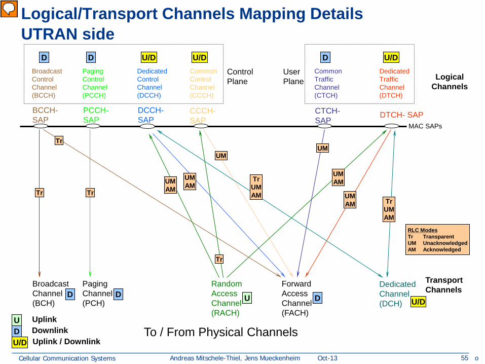
Logical/Transport Channels Mapping Details UTRAN side
Broadcast Channel (BCH)
Paging Channel (PCH)
Forward Access Channel (FACH)
Random Access Channel (RACH)
Dedicated Channel (DCH)
BCCH-SAP
DCCH-SAP
CCCH- SAP
PCCH-SAP DTCH- SAP
Transport Channels
MAC SAPs
CTCH- SAP
To / From Physical Channels
Logical Channels
Broadcast Control Channel (BCCH)
Paging Control Channel (PCCH)
Dedicated Control Channel (DCCH)
Common Control Channel (CCCH)
Common Traffic Channel (CTCH)
Dedicated Traffic Channel (DTCH)
U D U/D Uplink / Downlink
Uplink Downlink
U D D D U/D
U/D D D U/D U/D D
Tr
Tr
Tr UM AM
UM AM
Tr
Tr UM AM
UM
UM AM
UM AM Tr
UM AM
UM
Control Plane
User Plane
RLC Modes Tr Transparent UM Unacknowledged AM Acknowledged
o
Vorführender
Präsentationsnotizen
Tr: empty, possibly segmentation UM: error detection, no correction Q: why Transparent mode for BCH and PCH?
Cellular Communication Systems 56 Andreas Mitschele-Thiel, Jens Mueckenheim Oct-13
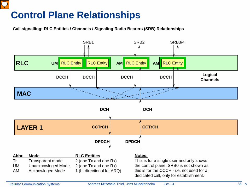
Abbr. Mode RLC Entities Tr Transparent mode 2 (one Tx and one Rx) UM Unacknowleged Mode 2 (one Tx and one Rx) AM Acknowleged Mode 1 (bi-directional for ARQ)
SRB1 SRB2 SRB3/4
Notes: This is for a single user and only shows the control plane. SRB0 is not shown as this is for the CCCH - i.e. not used for a dedicated call, only for establishment.
RLC Entity RLC Entity UM RLC Entity AM RLC Entity AM
MAC
Logical Channels DCCH DCCH DCCH DCCH
DCH
LAYER 1 CCTrCH
DCH
CCTrCH
DPDCH DPDCH
o
Vorführender
Präsentationsnotizen
separate RLC entities für UM, single joint entity for AM
Cellular Communication Systems 57 Andreas Mitschele-Thiel, Jens Mueckenheim Oct-13
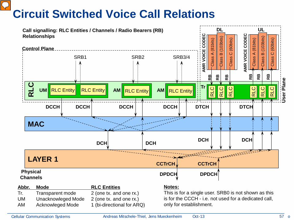
Abbr. Mode RLC Entities Tr. Transparent mode 2 (one tx. and one rx.) UM Unacknowleged Mode 2 (one tx. and one rx.) AM Acknowleged Mode 1 (bi-directional for ARQ)
SRB1 SRB2 SRB3/4
Notes: This is for a single user. SRB0 is not shown as this is for the CCCH - i.e. not used for a dedicated call, only for establishment.
RLC Entity RLC Entity UM RLC Entity AM
MAC
DCCH DCCH DCCH DCCH
LAYER 1 CCTrCH
RLC
RLC
RLC
RLC
RLC
RLC
Cla
ss A
(81b
its)
Cla
ss B
(103
bits
)
Cla
ss C
(60b
its)
AMR
VO
ICE
CO
DEC
DL
Cla
ss A
(81b
its)
Cla
ss B
(103
bits
)
Cla
ss C
(60b
its)
AMR
VO
ICE
CO
DEC
UL
Tr
RB
RB
RB
RB
RB
RB
DTCH DTCH
Control Plane
Use
r Pla
ne
DCH DCH
DPDCH Physical Channels
RLC Entity AM
DCH DCH
CCTrCH
DPDCH
o
Vorführender
Präsentationsnotizen
Questions: why two RLC instances for a single SRB1 => no ACK and no retransmission, just an error check => no state to share between UL and DL! same for voice communication! here no function at all
Cellular Communication Systems 58 Andreas Mitschele-Thiel, Jens Mueckenheim Oct-13
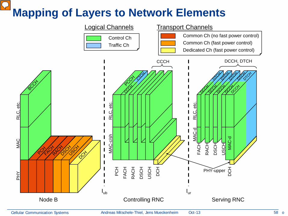
Mapping of Layers to Network Elements R
LC, e
tc.
PHY
MAC
Node B
CCCH DCCH, DTCH
MAC
-c/s
h
MAC
-d
MAC
-d
PHY-upper
RLC
, etc
.
RLC
, etc
. Controlling RNC Serving RNC
Iub Iur
PCH
FAC
H
RAC
H
DSC
H
USC
H
DC
H
FAC
H
RAC
H
DSC
H
USC
H
DC
H
Common Ch (no fast power control) Common Ch (fast power control) Dedicated Ch (fast power control)
Control Ch Traffic Ch
Logical Channels Transport Channels
o
Vorführender
Präsentationsnotizen
The protocol stacks are distributed across different network elements in the UTRAN. This is indicated in the slide, and occurs as follows: The Node B runs the entire stack for the Broadcast Control Channel (BCCH), and the physical layer for all other channels, except that the upper sub-layer of the DCH physical channel, which is concerned with macrodiversity distirbution and combining, is in an RNC. The Controlling RNC (CRNC), which is the RNC which has responsibility for the Node B in question, runs the MAC layer and above for the Paging Control Channels (PCCH), the Common Control Channels (CCCH) and the Common Traffic Channels (CTCH). The controlling RNC also has some responsibility for all traffic through MAC layers which run above the common transport channels, to perform functions such as scheduling, flow control and UE identification. The Controlling RNC can also be instructed to perform macrodiversity distribution/combining above the DCH, in order to reduce Iur traffic to the Serving RNC. The Serving RNC (SRNC) is the RNC which serves a particular UE, and only exists in relationship to dedicated channels. It contains the portion of the MAC layer for these channels concerned with MAC multiplexing, and all MAC functionality above the DCH (i.e. including scheduling). It can also perform macrodiversity distribution/combining (PHY-upper functionality). Note that for some UEs, the Serving RNC will also be the Controlling RNC.
Cellular Communication Systems 63 Andreas Mitschele-Thiel, Jens Mueckenheim Oct-13
L3
cont
rol
cont
rol
cont
rol
cont
rol
Logical Channel
Transport Channels
C-plane signalling U-plane information
PHY
L2/MAC
L1
RLC
DC Nt GC
L2/RLC
MAC
RLC RLC
RLC RLC
RLC RLC
RLC
Duplication avoidance
UuS boundary
BMC L2/BMC
control
PDCP PDCP L2/PDCP
DC Nt GC
Radio Bearers
RRC
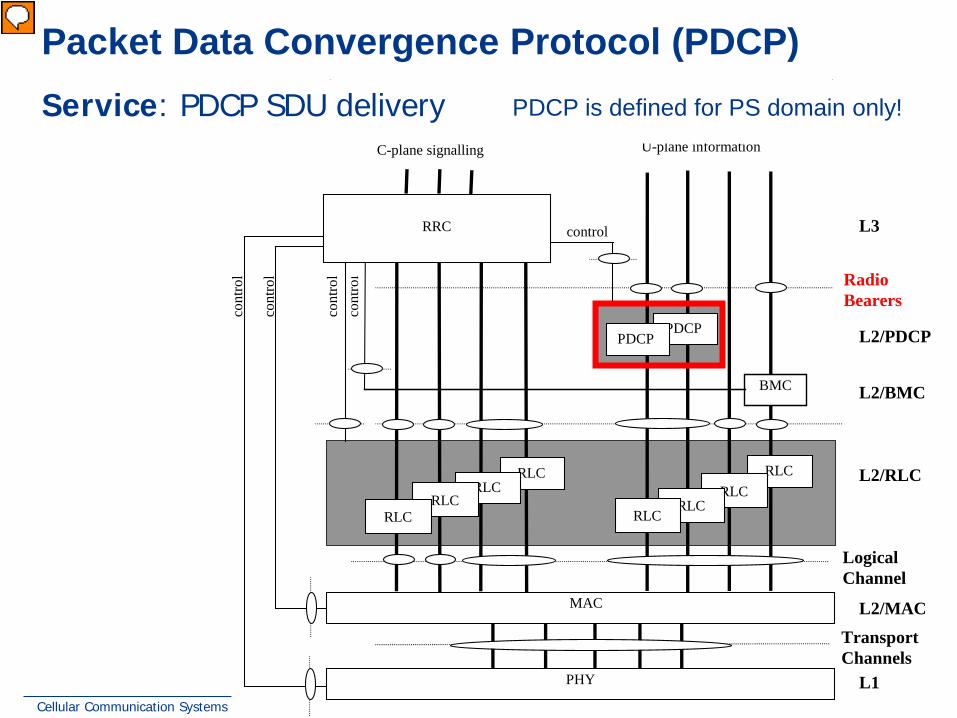
Radio Access Bearers AS control plane SAPs Packet Data Convergence Protocol (PDCP)
Service: PDCP SDU delivery PDCP is defined for PS domain only!
Vorführender
Präsentationsnotizen
5.3.3 PDCP Services and Function (copy from 25.301-4.1.0) This subclause provides an overview on services and functions provided by the Packet Data Convergence Protocol (PDCP). A detailed description of the PDCP is given in [10]. 5.3.3.1PDCP Services provided to upper layers -PDCP SDU delivery. 5.3.3.2PDCP Functions -Header compression and decompression. Header compression and decompression of IP data streams (e.g., TCP/IP and RTP/UDP/IP headers) at the transmitting and receiving entity, respectively. The header compression method is specific to the particular network layer, transport layer or upper layer protocol combinations e.g. TCP/IP and RTP/UDP/IP. -Transfer of user data. Transmission of user data means that PDCP receives PDCP SDU from the NAS and forwards it to the RLC layer and vice versa. -Support for lossless SRNS relocation. Maintenance of PDCP sequence numbers for radio bearers that are configured to support lossless SRNS relocation.
Cellular Communication Systems 64 Andreas Mitschele-Thiel, Jens Mueckenheim Oct-13
PDCP – Functions
Header compression and decompression • Header compression and decompression of IP data streams (e.g.
TCP/IP and RTP/UDP/IP headers) Header compression method is specific to the upper layer protocol
combinations, e.g. TCP/IP or RTP/UDP/IP (RFC 2507 & RFC 3095) Transfer of user data • PDCP receives PDCP SDU from the NAS and forwards it to the RLC layer
and vice versa Support for lossless SRNS relocation • Maintenance of PDCP sequence numbers for radio bearers that are
configured to support lossless SRNS relocation
Vorführender
Präsentationsnotizen
5.3.3 PDCP Services and Function (copy from 25.301-4.1.0) This subclause provides an overview on services and functions provided by the Packet Data Convergence Protocol (PDCP). A detailed description of the PDCP is given in [10]. 5.3.3.1PDCP Services provided to upper layers -PDCP SDU delivery. 5.3.3.2PDCP Functions -Header compression and decompression. Header compression and decompression of IP data streams (e.g., TCP/IP and RTP/UDP/IP headers) at the transmitting and receiving entity, respectively. The header compression method is specific to the particular network layer, transport layer or upper layer protocol combinations e.g. TCP/IP and RTP/UDP/IP. -Transfer of user data. Transmission of user data means that PDCP receives PDCP SDU from the NAS and forwards it to the RLC layer and vice versa. -Support for lossless SRNS relocation. Maintenance of PDCP sequence numbers for radio bearers that are configured to support lossless SRNS relocation.
Cellular Communication Systems 66 Andreas Mitschele-Thiel, Jens Mueckenheim Oct-13
L3
cont
rol
cont
rol
cont
rol
cont
rol
Logical Channel
Transport Channels
C-plane signalling U-plane information
PHY
L2/MAC
L1
RLC
DC Nt GC
L2/RLC
MAC
RLC RLC
RLC RLC
RLC RLC
RLC
Duplication avoidance
UuS boundary
BMC L2/BMC
control
PDCP PDCP L2/PDCP
DC Nt GC
Radio Bearers
RRC
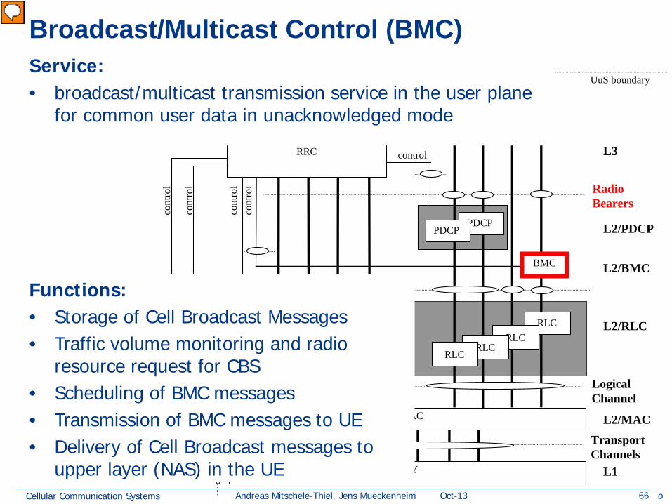
Broadcast/Multicast Control (BMC)
Functions: • Storage of Cell Broadcast Messages • Traffic volume monitoring and radio
resource request for CBS • Scheduling of BMC messages • Transmission of BMC messages to UE • Delivery of Cell Broadcast messages to
upper layer (NAS) in the UE
Service: • broadcast/multicast transmission service in the user plane
for common user data in unacknowledged mode
o
Vorführender
Präsentationsnotizen
5.3.4Broadcast/Multicast Control - Services and functions (copy from 25.301-4.1.0) This subclause provides an overview on services and functions provided by the BMC sublayer. A detailed description of the BMC protocol is given in [10]. 5.3.4.1BMC Services The BMC-SAP provides a broadcast/multicast transmission service in the user plane on the radio interface for common user data in unacknowledged mode. 5.3.4.2BMC Functions -Storage of Cell Broadcast Messages.�The BMC stores the Cell Broadcast messages received over the CBC-RNC interface for scheduled transmission. -Traffic volume monitoring and radio resource request for CBS.�At the UTRAN side, the BMC calculates the required transmission rate for Cell Broadcast Service based on the messages received over the CBC-RNC interface, and requests for appropriate CTCH/FACH resources from RRC. -Scheduling of BMC messages.�The BMC receives scheduling information together with each Cell Broadcast message over the CBC-RNC-interface. Based on this scheduling information, at the UTRAN side, BMC generates schedule messages and schedules BMC message sequences accordingly. At the UE side, BMC evaluates the schedule messages and indicates scheduling parameters to RRC, which are used by RRC to configure the lower layers for CBS discontinuous reception. -Transmission of BMC messages to UE.�This function transmits the BMC messages (Scheduling and Cell Broadcast messages) according to schedule. -Delivery of Cell Broadcast messages to upper layer (NAS).�This functions delivers the received Cell Broadcast messages to upper layer (NAS) in the UE. Only non-corrupted Cell Broadcast messages are delivered.
Cellular Communication Systems 67 Andreas Mitschele-Thiel, Jens Mueckenheim Oct-13
L3
cont
rol
cont
rol
cont
rol
cont
rol
Logical Channel
Transport Channels
C-plane signalling U-plane information
PHY
L2/MAC
L1
RLC
DC Nt GC
L2/RLC
MAC
RLC RLC
RLC RLC
RLC RLC
RLC
Duplication avoidance
UuS boundary
BMC L2/BMC
control
PDCP PDCP L2/PDCP
DC Nt GC
Radio Bearers
RRC
Radio Resource Control (RRC)
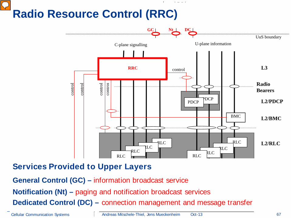
Services Provided to Upper Layers
General Control (GC) – information broadcast service
Notification (Nt) – paging and notification broadcast services Dedicated Control (DC) – connection management and message transfer
Vorführender
Präsentationsnotizen
Refer to slide 28 with global view on AS and NAS
Cellular Communication Systems 68 Andreas Mitschele-Thiel, Jens Mueckenheim Oct-13
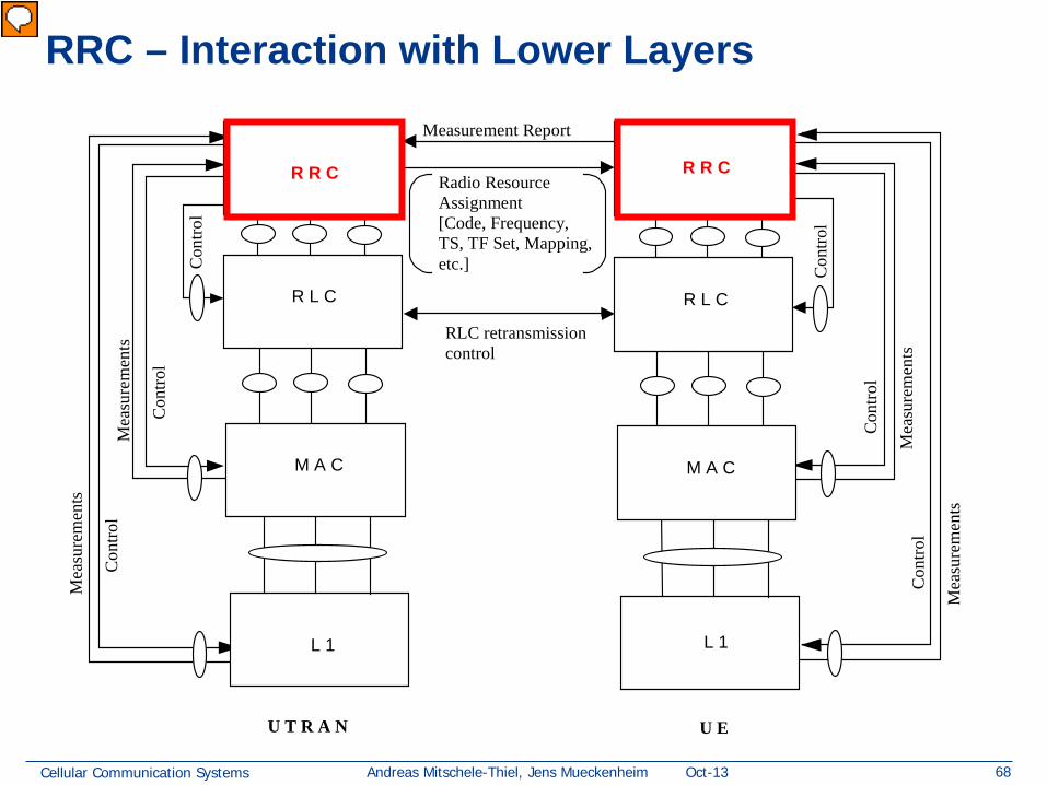
RRC – Interaction with Lower Layers
R R C R R C
R L C R L C
Radio Resource Assignment [Code, Frequency, TS, TF Set, Mapping, etc.]
Measurement Report
RLC retransmission control
L 1 L 1
U T R A N U E
Con
trol
Mea
sure
men
ts
Con
trol
Mea
sure
men
ts
Con
trol
Mea
sure
men
ts
Con
trol
Mea
sure
men
ts
M A C M A C
Con
trol
Con
trol
Vorführender
Präsentationsnotizen
Frage: UE schickt measurement report wegen HO-Anforderungen; was passiert in der Folge?
Cellular Communication Systems 69 Andreas Mitschele-Thiel, Jens Mueckenheim Oct-13
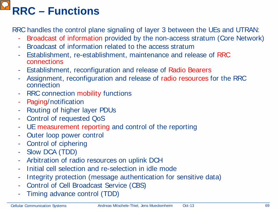
RRC – Functions RRC handles the control plane signaling of layer 3 between the UEs and UTRAN:
- Broadcast of information provided by the non-access stratum (Core Network) - Broadcast of information related to the access stratum - Establishment, re-establishment, maintenance and release of RRC
connections - Establishment, reconfiguration and release of Radio Bearers - Assignment, reconfiguration and release of radio resources for the RRC
connection - RRC connection mobility functions - Paging/notification - Routing of higher layer PDUs - Control of requested QoS - UE measurement reporting and control of the reporting - Outer loop power control - Control of ciphering - Slow DCA (TDD) - Arbitration of radio resources on uplink DCH - Initial cell selection and re-selection in idle mode - Integrity protection (message authentication for sensitive data) - Control of Cell Broadcast Service (CBS) - Timing advance control (TDD)
Vorführender
Präsentationsnotizen
The RRC performs the following functions (25.301, ch 5.4.2): -Broadcast of information provided by the non-access stratum (Core Network). The RRC layer performs system information broadcasting from the network to all UEs. The system information is normally repeated on a regular basis. The RRC layer performs the scheduling, segmentation and repetition. This function supports broadcast of higher layer (above RRC) information. This information may be cell specific or not. As an example RRC may broadcast Core Network location service area information related to some specific cells. -Broadcast of information related to the access stratum. The RRC layer performs system information broadcasting from the network to all UEs. The system information is normally repeated on a regular basis. The RRC layer performs the scheduling, segmentation and repetition. This function supports broadcast of typically cell-specific information. -Establishment, re-establishment, maintenance and release of an RRC connection between the UE and UTRAN. The establishment of an RRC connection is initiated by a request from higher layers at the UE side to establish the first Signalling Connection for the UE. The establishment of an RRC connection includes an optional cell re-selection, an admission control, and a layer 2 signalling link establishment. The release of an RRC connection can be initiated by a request from higher layers to release the last Signalling Connection for the UE or by the RRC layer itself in case of RRC connection failure. In case of connection loss, the UE requests re-establishment of the RRC connection. In case of RRC connection failure, RRC releases resources associated with the RRC connection. -Establishment, reconfiguration and release of Radio Bearers. The RRC layer can, on request from higher layers, perform the establishment, reconfiguration and release of Radio Bearers in the user plane. A number of Radio Bearers can be established to an UE at the same time. At establishment and reconfiguration, the RRC layer performs admission control and selects parameters describing the Radio Bearer processing in layer 2 and layer 1, based on information from higher layers. -Assignment, reconfiguration and release of radio resources for the RRC connection. The RRC layer handles the assignment of radio resources (e.g. codes, CPCH channels) needed for the RRC connection including needs from both the control and user plane. The RRC layer may reconfigure radio resources during an established RRC connection. This function includes coordination of the radio resource allocation between multiple radio bearers related to the same RRC connection. RRC controls the radio resources in the uplink and downlink such that UE and UTRAN can communicate using unbalanced radio resources (asymmetric uplink and downlink). RRC signals to the UE to indicate resource allocations for purposes of handover to GSM or other radio systems. -RRC connection mobility functions. The RRC layer performs evaluation, decision and execution related to RRC connection mobility during an established RRC connection, such as handover, preparation of handover to GSM or other systems, cell re-selection and cell/paging area update procedures, based on e.g. measurements done by the UE. -Paging/notification. The RRC layer can broadcast paging information from the network to selected UEs. Higher layers on the network side can request paging and notification. The RRC layer can also initiate paging during an established RRC connection. -Routing of higher layer PDUs. This function performs at the UE side routing of higher layer PDUs to the correct higher layer entity, at the UTRAN side to the correct RANAP entity. -Control of requested QoS. This function shall ensure that the QoS requested for the Radio Bearers can be met. This includes the allocation of a sufficient number of radio resources. -UE measurement reporting and control of the reporting. The measurements performed by the UE are controlled by the RRC layer, in terms of what to measure, when to measure and how to report, including both UMTS air interface and other systems. The RRC layer also performs the reporting of the measurements from the UE to the network. -Outer loop power control. The RRC layer controls setting of the target of the closed loop power control. -Control of ciphering. The RRC layer provides procedures for setting of ciphering (on/off) between the UE and UTRAN. Details of the security architecture are specified in [15]. -Slow DCA. Allocation of preferred radio resources based on long-term decision criteria. It is applicable only in TDD mode. - Arbitration of radio resources on uplink DCH. This function controls the allocation of radio resources on uplink DCH on a fast basis, using a broadcast channel to send control information to all involved users. NOTE: This function is implemented in the CRNC. -Initial cell selection and re-selection in idle mode. Selection of the most suitable cell based on idle mode measurements and cell selection criteria. -Integrity protection. This function adds a Message Authentication Code (MAC-I) to those RRC messages that are considered sensitive and/or contain sensitive information. The mechanism how the MAC-I is calculated is described in [14]. -Initial Configuration for CBS�This function performs the initial configuration of the BMC sublayer. -Allocation of radio resources for CBS�This function allocates radio resources for CBS based on traffic volume requirements indicated by BMC. The radio resource allocation set by RRC (i.e. the schedule for mapping of CTCH onto FACH/S-CCPCH) is indicated to BMC to enable generation of schedule messages. The resource allocation for CBS shall be broadcast as system information. -Configuration for CBS discontinuous reception�This function configures the lower layers (L1, L2) of the UE when it shall listen to the resources allocated for CBS based on scheduling information received from BMC. -Timing advance control. The RRC controls the operation of timing advance. It is applicable only in 3.84 Mcps TDD.
Cellular Communication Systems 70 Andreas Mitschele-Thiel, Jens Mueckenheim Oct-13
RRC State Machine
• RRC state machine exists as two peer entities (MS and UTRAN) • The two peer entities are synchronized (apart from transient situations
and error cases)
Idle mode
CellConnected
RRCconnectionestablishment
URAConnected
RRCconnectionrelease
Enter URAconnected state
Enter cellconnected state
Connected mode
Vorführender
Präsentationsnotizen
The RRC state machine is a description model of how the MS and the UTRAN co-operate regarding RRC functionality. The RRC state describes the MS state in the UTRAN. This subclause contains a brief description of the RRC state machine, for more information see 3G TS 25.303.
Cellular Communication Systems 71 Andreas Mitschele-Thiel, Jens Mueckenheim Oct-13
UTRAN Registration Area (URA)
LA
RA
RA
RA RA
RA
RA RA
RA
RA
URA
URA URA
URA URA
URA
URA URA
URA URA
URA
URA URA
URA URA
URA
URA URA
URA URA
URA
URA URA
URA URA
URA
URA URA
URA URA
URA
URA URA
URA URA
URA
URA URA
URA URA
URA
URA URA
URA URA
• URA is known to the UTRAN only
• URA is established in RRC connected mode
URA is independent of RNC area
URA may cover
•part of an RNC area
•parts of several RNC areas
URAs may overlap
URA
URA URA U
RA
URA
URA
URA
URA
URA
URA
URA
Cellular Communication Systems 72 Andreas Mitschele-Thiel, Jens Mueckenheim Oct-13
RRC State Machine
Idle mode
CellConnected
RRCconnectionestablishment
URAConnected
RRCconnectionrelease
Enter URAconnected state
Enter cellconnected state
Connected mode
RRC Idle mode: – no connection established between the MS and UTRAN – no signalling between UTRAN and the MS except for system
information sent from UTRAN on a broadcast channel to the MS – MS can only receive paging messages with a CN identity on the PCH – no information of the MS is stored in UTRAN
Vorführender
Präsentationsnotizen
The RRC state machine is a description model of how the MS and the UTRAN co-operate regarding RRC functionality. The RRC state describes the MS state in the UTRAN. This subclause contains a brief description of the RRC state machine, for more information see 3G TS 25.303.
Cellular Communication Systems 73 Andreas Mitschele-Thiel, Jens Mueckenheim Oct-13
RRC State Machine
RRC Connected mode: – two main states
• Cell Connected: MS position is known at the cell level; RRC connection mobility is handled by handover and cell update procedures
• URA Connected: MS position is known at the URA level; URA updating procedures provide the mobility functionality; no dedicated radio resources are used in the state.
– there is one RNC that is acting as serving RNC, and an RRC connection is established between the MS and this SRNC
An UE has either zero or one RRC connection
Idle mode
CellConnected
RRCconnectionestablishment
URAConnected
RRCconnectionrelease
Enter URAconnected state
Enter cellconnected state
Connected mode
Vorführender
Präsentationsnotizen
The RRC state machine is a description model of how the MS and the UTRAN co-operate regarding RRC functionality. The RRC state describes the MS state in the UTRAN. This subclause contains a brief description of the RRC state machine, for more information see 3G TS 25.303.
Cellular Communication Systems 74 Andreas Mitschele-Thiel, Jens Mueckenheim Oct-13
RRC State Machine: Details of connected mode
Establish RRC Connection
Release RRC Connection
UTRA RRC Connected Mode UTRA: Inter-RAT Handover
GSM: Handover
Establish RRC Connection
Release RRC Connection
URA_PCH CELL_PCH
GSM
Connected Mode
Establish RR Connection
Release RR Connection
Idle Mode
Camping on a UTRAN cell Camping on a GSM / GPRS cell
GPRS Packet Idle Mode
GPRS Packet
Transfer Mode
Initiation of temporary block flow
Release of temporary block flow
Cell reselection
CELL_DCH
out of service
in service
CELL_FACH
out of service
in service
out of service
in service
URA_PCH or CELL_PCH state
Neither DCCH nor DTCH are available in these states
CELL_FACH state
DCCH and, if configured, DTCH are available in this state
CELL_DCH state
DCCH and DTCH are available in this state
Vorführender
Präsentationsnotizen
7.2Processes in UE modes/states (excerpt from 25.331-420) NOTE:This subclause specifies what processes shall be active in the UE in the different RRC modes/states. The related procedures and the conditions on which they are triggered are specified either in clause 8 or elsewhere in the relevant process definition. 7.2.1UE Idle mode UE processes that are active in UE Idle mode are specified in [4]. The UE shall perform a periodic search for higher priority PLMNs as specified in [25] 7.2.2UTRA RRC Connected mode In this specification unless otherwise mentioned "connected mode" shall refer to "UTRA RRC connected mode". 7.2.2.1URA_PCH or CELL_PCH state In the URA_PCH or CELL_PCH state the UE shall perform the following actions: NOTE:Neither DCCH nor DTCH are available in these states. -if the UE is "in service area": -maintain up-to-date system information as broadcast by the serving cell as specified in the sub-clause 8.1.1; -perform cell reselection process as specified in [4]; -perform a periodic search for higher priority PLMNs as specified in [25]; -monitor the paging occasions and PICH monitoring occasions determined according to subclause 8.6.3.1a and 8.6.3.2 and receive paging information on the PCH mapped on the S-CCPCH selected by the UE according to the procedure in subclause 8.5.19; -act on RRC messages received on PCCH and BCCH; -perform measurements process according to measurement control information as specified in subclause 8.4 and in subclause 14.4; -maintain up-to-date BMC data if it supports Cell Broadcast Service (CBS) as specified in [37]; -run timer T305 for periodical URA update if the UE is in URA_PCH or for periodical cell update if the UE is in CELL_PCH; -if the UE is "out of service area": -perform cell reselection process as specified in [4]; -run timer T316; -run timer T305 7.2.2.2CELL_FACH state In the CELL_FACH state the UE shall perform the following actions: NOTE:DCCH and, if configured, DTCH are available in this state. -if the UE is "in service area": -maintain up-to-date system information as broadcast by the serving cell as specified in subclause 8.1.1; -perform cell reselection process as specified in [4]; -perform measurements process according to measurement control information as specified in subclause 8.4 and in subclause 14.4; -run timer T305 (periodical cell update); -listen to all FACH transport channels mapped on the S-CCPCH selected by the UE according to the procedure in subclause 8.5.19; -act on RRC messages received on BCCH, CCCH and DCCH; -act on RRC messages received on, if available, SHCCH (TDD only); -if the UE is "out of service area": -perform cell reselection process as specified in [4]; -run timers T305 (periodical cell update), and T317 (cell update when re-entering "in service") or T307 (transition to Idle mode) 7.2.2.3CELL_DCH state In the CELL_DCH state the UE shall perform the following actions: NOTE:DCCH and, if configured, DTCH are available in this state. -read system information broadcast on FACH as specified in subclause 8.1.1.3 (applicable only to UEs with certain capabilities and in FDD mode); -read the system information as specified in subclause 8.1.1 (for UEs in TDD mode); -perform measurements process according to measurement control information as specified in subclause 8.4 and in clause 14; -act on RRC messages received on DCCH; -act on RRC messages received on BCCH (applicable only to UEs with certain capabilities and in FDD mode); -act on RRC messages received on BCCH (TDD only) and, if available, SHCCH (TDD only).
Cellular Communication Systems 75 Andreas Mitschele-Thiel, Jens Mueckenheim Oct-13
UMTS RRC State Optimization (PS mode) Goal: Minimization of Radio Resource Consumption during Idle Times Tradeoff for idle periods • retaining in state => continuous state cost or • move to cheaper state => one time transition cost
Limited resources • radio resources (transmit power) • channelization codes • processing cost (signaling) • power consumption • transport resources (Iu, Iub, …) Find optimal timeout settings depending on • traffic model (distribution of idle times) • cost per state • cost per transition • user mobility • …
cell_DCH
URA_PCH
cell_PCH
idle
T1
T2
T3
Vorführender
Präsentationsnotizen
Für die LOGN-Verteilung eignen sich z.B. folgende Parameter: ��Zustandskosten: 16, 4, 1, 0.04 �Transitionskosten: 1, 1, 1, 20, 35, 50 �(Reihenfolge wie im Programm von oben nach unten)
Cellular Communication Systems 76 Andreas Mitschele-Thiel, Jens Mueckenheim Oct-13
UMTS RRC State Optimization O
ptim
izat
ion
of T
imeo
ut V
alue
s
sum
state cost
transition cost
Cellular Communication Systems 77 Andreas Mitschele-Thiel, Jens Mueckenheim Oct-13
MSC/VLR or SGSN
SRNC UE
Radio Interface – Control Plane Summary
RRC Connection RANAP Connection
RRC RANAP RRC RANAP
Signaling Connection (GC, Nt, DC)
Radio Access Bearer
AS Signaling Radio Bearer Iu Signaling Bearer
Higher layer control
Higher layer control
2
NAS Signaling Radio Bearer
Vorführender
Präsentationsnotizen
RRC Connection; A point-to-point bi-directional connection between RRC peer entities on the UE and the UTRAN sides, respectively. This is not quite consistent with the figure!