Embed Size (px)
Citation preview

Owner’s Manual
HTX-8800-U
Ultra HD/4K 8x8 HDMI to HDBaseT Matrix Switcher with POE and HDCP 2.2
PureLinkTM
535 East Crescent Avenue
Ramsey, NJ 07446 USA
Tel: +1.201.488.3232 Fax: +1.201.621.6118
E-mail: [email protected] www.purelinkav.com
For order support, please contact your local dealer.
For technical support, please contact us at [email protected]
PureLink by Dtrovision
2
TABLE OF CONTENTS
Chapter 1. Product Overview, Operation & Specification
1.1 Safety Precautions --------------------------------------------------------------- 3
1.2 Declaration of Conformity --------------------------------------------------------------- 4
1.3 What’s in the Box --------------------------------------------------------------- 4
1.4 Product Introduction --------------------------------------------------------------- 5
1.5 Front View --------------------------------------------------------------- 6
1.6 Front Panel Button Operation ----------------------------------------------------- 6
1.7 Rear View --------------------------------------------------------------- 8
1.8 HTX-Rx --------------------------------------------------------------- 9
1.9 Product Specification --------------------------------------------------------------- 10
1.10 IR Remote Control ------------------------------------------------------------- 12
1.11 IR Control ------------------------------------------------------------- 12
1.12 Cable Termination ------------------------------------------------------------- 13
1.13 Installation Guidelines ------------------------------------------------------------ 16
1.14 Communication Settings ------------------------------------------------------------ 16
Chapter 2. Communication Code Configuration
2.1 Control Programmer’s Guide ---------------------------------------------------- 17
2.2 Overview ---------------------------------------------------------------------- 17
2.3 Command Code Formats ----------------------------------------------------------- 17
2.4 General Rules for Command Codes --------------------------------------------- 18
2.5 Command Ack Value Response ---------------------------------------------------- 19
2.6 Connecting Switches --------------------------------------------------------------- 20
2.7 Disconnecting Switches ----------------------------------------------------------- 21
2.8 Connection Status Check ----------------------------------------------------------- 22
Chapter 3. Additional Information
3.1 Manufacturer’s Warranty (3-Year) ------------------------------------------------- 24
3.2 Customer Service ------------------------------------------------------------------- 24

PureLink by Dtrovision
3
Chapter 1. Introduction
1.1 Safety Precautions
All safety instructions should be read and understood before the unit is operated.
The owner’s manual and safety instructions should be retained for future reference.
Unplug this unit from the wall outlet before cleaning. Do not use liquid or aerosol cleaners. Use a damp
cloth only.
Keep away from wet, magnetic, and flammable surfaces or substances.
Always use the correct power supply (indicated on the product label) when operating this unit.
This unit may be equipped with a 3 wire grounding-type plug - a plug having a third (grounding) pin.
This pin will only fit in to a grounding type power outlet. If you are unable to insert the plug in to the
outlet, contact your electrician to replace your obsolete outlet.
Air vents should be kept clean and unobstructed at all times.
Please refrain from using frayed power cords and damaged wall outlets.
Do not place any heavy objects or equipment on top of the unit.
If you experience any malfunctioning of product or have any question as to operation of the
product, please contact our customer service center.
PureLinkTM
Tel: 201.488.3232
Email: [email protected]

PureLink by Dtrovision
4
1.2 Declaration of Conformity
According to Council Directive 73/23/EEC (February 19, 1973) on the Harmonization of the Laws of
Member States relating to Electrical Equipment; Council Directive 89/336/EEC (May 3, 1989) on
Electromagnetic Compatibility; Council Directive 93/68/EEC (July 22, 1993)-Amending Directives
89/336/EEC (MC) and 73/23/EEC (Low Voltage Equipment Safety), and/or CPU Boards and Power
Supplies used Council Directive 93/68/EEC with Matrix, Dtrovision LLC, 535 E Crescent Ave Ramsey, NJ
07446 201-488-3232, declares under sole responsibility, that the product identifies with 93/66/EEC of the
Council Directive Low Voltage Equipment Safety. Each product marketed is identical to the representative
unit tested and found to be compliant with the standards.
1.3 What’s in the Box
Main Frame: HTX-8800-U
Power cord
9 x IR Tx cable
10 x IR Rx cable
Phoenix connectors for RS232
IR remote
RS-232C & LAN cables
Rack Ears
Owner’s manual

PureLink by Dtrovision
5
1.4 Product Introduction
The new HTX-8800-U Ultra HD/4K HDMI to HDBaseT & HDMI mirrored outs with POE and HDCP 2.2
provides switching for up to eight (8) HDMI to any eight (8) HDBaseT outputs and (8) mirrored HDMI
outputs. PureLink’s legendary EDID/HDCP Management System, consistently praised by system
integrators as the most reliable in the industry. Together with full HDCP v 2.2, PureLink’s uncompromising
design and manufacturing standards, the HTX-8800-U delivers unparalleled quality and value.
* Features
(8) Ultra HD/4K source devices independently switchable to (8) Ultra HD/4K destinations
Ultra HD/4K support with HDCP v2.2 compliance
HDBaseT™ 5-play technology for Ultra HD/4K video, HD multichannel audio distribution,
bi-directional control via IR, RS-232 and LAN, Ethernet switching, and POE
Mirrored HDMI/HDBaseT™ outputs, providing up to 16 ports
o (8) HDBaseT™ outputs for remote destinations (@100m)
o (8) HDMI outputs for local destinations, such as in-room displays, AVRs, and switchers
Audio de-embedding for each output via (1) 3.5mm analog stereo or (1) RCA coaxial digital
output
Auto EDID management (EDID library and EDID emulation)
Full 3D compatibility (up to 1080p)
Supports Dolby TrueHD, Dolby Digital Plus and DTS-HD Master Audio plus LPCM (up to 192kHz)
Ideal for multi-zone applications to distribute A/V with control
DVI and DisplayPort support via HDMI ports with adapters (sold separately)
Includes IR remote for basic matrix switching
Front panel LCD display for easy menu navigation and status check
Compact 19’’ standard 2RU rack-mountable chassis
HDMI v1.4b uncompressed video/audio up to 10.2 Gbps
Integrated Ethernet switch serves LAN to all connected zones
HDBaseT outputs directly drive HTX extender receivers (sold separately) up to 330ft (100m)
TCP/IP, RS-232, IR and front panel control
Bundle kits available with receivers
3-year parts and labor warranty, extends to 5-year when used exclusively with PureLink
TotalWire™ CATx cable (some restrictions may apply, ask factory for details)

PureLink by Dtrovision
6
1.5 Front View of HTX-8800-U
The HTX-8800-U chassis is mountable on 19” standard rack with brackets. On front panel, there are some
function keys, input-output buttons and a status display window placed as shown in Figure 1-1.
<Front Panel>
(Figure 1-1)
POWER: Main power switch ON / OFF
DISPLAY: View menu and system mode
MENU: EDID setup menu
UP: Up button
DOWN: Down button
ENTER: Execution button
1.6 Front panel button operation
Creating a switching
Press Output # button
Press Input # button
Switching is completed
EDID
Press MENU button
Use Up and Down buttons to select EDID from the EDID library list
Press Enter button
Select input# which you want to save selected EDID to
Press Enter button

PureLink by Dtrovision
7
EDID
HTX series matrix switcher provides Auto EDID management system; easy and fail safe way to handle EDID,
via EDID library system and EDID emulation.
What's EDID?
Extended Display Identification Data (EDID) is an information set that digital display provides to describe its
capabilities to a Video source. Video source will know what kinds of displays are connected and it will
determine which resolution to Output according to the EDID information received from the display.
The EDID normally includes manufacturer name and serial number, sets of capable resolution including native
resolution, supported timing, pixel mapping data (for digital displays only) and etc.
In a digital connectivity environment; in order to support the maximum resolution of connected monitor, EDID
handshake is a critical because improper EDID handshake between sources to the display will result in no
image on the display.
EDID handshake may sound simple; however, with multiple peripheral devices within the chain, display's EDID
information easily get lost or blocked while it is traveling to the source device.
HTX series matrix switcher provides Auto EDID management system to meet today's sophisticated digital
connectivity integration environment.
Auto EDID management system
EDID library
15 most widely used EDID data is pre-programmed internal EEPROM chipset which user can take and save
onto the any of the matrix switcher's Input EEPROM.
EDID library list
1080p, 2 ch audio 1080p, dolby/dts 5.1 1080p, HD audio
1080i, 2 ch audio 1080i, dolby/dts 5.1 1080i, HD audio
3D, 1080p, 2 ch audio 3D, 1080p, dolby/dts 5.1 3D, 1080p, HD audio
4K@30Hz, 2 ch audio 4K@30Hz, dolby/dts 5.1 4K@30Hz, HD audio
4K@60Hz, 2 ch audio 4K@60Hz, dolby/dts 5.1 4K@60Hz, HD audio
Factory default EDID is set to 1920 x 1080p@60Hz
By optimizing factory default EDID and EDID library feature, in most cases, HTX series matrix switcher will
work out of the box without any additional configuration.

PureLink by Dtrovision
8
Emulation
The user can easily save an EDID data from any display devices directly onto the matrix switcher’s input port.
By saving display device's EDID information on the matrix switcher input port, input port will act as a display to
the video source.
Note) There may be display devices that are not allowing other device to emulate its EDID
data.
Note) Certain EDID data may not be compatible with some devices, in this case, it is
recommended to use scaling option
1.7 Rear View of HTX-8800-U
<Back Panel>
(Figure 1-2)
① IR EXT, IN/OUT: IR ext is for HTX-8800-U control, IR Inputs, and IR outputs are for IR communication on
HDBT outputs pass-thru
② Control Interface: LAN (TCP/IP) and RS232 control ports
③ 8 x HDMI inputs
④ Each output consists with
1 x HDBaseT,
1 x HDMI,
1 x bi-directional RS232,
1 x 3.5mm analog audio extraction,
1 x digital coaxial audio extraction port
* Signals are outputting simultaneously to on each output’s HDMI, HDBaseT, 3.5mm analog audio, and
digital coaxial ports
⑤ ETHERNET: Integrated Ethernet switch serves LAN to all connected zones (HDBaseT Rx)

PureLink by Dtrovision
9
⑥ AC Power: IEC power connector
1.8 HTX-Rx
HDMI OUT: HDMI output port
ETHERNET: Provides internet connection to the connected device
RS232: Provides bi-directional serial control to the connected device
DC IN: Optional 24V DC power supply connector
IR TX/RX: Provides bi-directional IR control to the connected device
HDBASET IN: Receives HDBaseT signal from HTX series matrix switcher ’s HDBaseT output
* There are LED signal status indicators next HDMI output port and HDBaseT input port
<Application diagram>

PureLink by Dtrovision
10
1.9 Product Specifications
HTX-8800-U General Specification
Power AC power supply
(US/EU standards, CE/FCC/UL certified)
Operational Temperature 32° ~ 117° F (0° to 47° C)
Storage Temperature - 4° ~ 140° F (-20° to 60° C)
Humidity 0 ~ 90% non-condensing
MTBF 50,000 hours
Dimensions (W x D x H) 17.3'' x 14.3'' x 3.5'' (440 x 362 x 88mm)
Shipping Dimensions (with cover box) TBD
Rack mounting Yes, 19'' standard rack, 2RU
Weight 14.8 lbs (6.7 kg)
Shipping Weight
(with accessories and cover box)
TBD
* Functional Specification
Communication
HDMI HDMI v1.4b, HDCP v2.2, EDID
RS-232 2-way device control and monitoring. Fixed baud rate at 115200, 8 data bits, no parity,
and 2 stop bits
LAN TCP/IP (Default IP: 192.168.0.100)
Video
Switcher HDMI input, HDBaseT & HDMI output 8x8 matrix switcher
Input Signal Types HDMI, DVI, Displayport
Output Signal Types HDMI, DVI, Displayport
Formats HDMI v1.4b, DVI 1.0, HDCP v2.2content protection support
HDMI Input resolutions
Ultra HD/4K up to 4096x2160 @24/25/30Hz (RGB/YCbCr 4:4:4 8 bits, YCbCr 4:2:2
8/10/12 bits), 4096 x 2160 @50/60Hz (YCbCr 4:2:0 8 bits)
PC resolution up to 1920 x 1200 @ 60Hz
Output Resolutions
(HDBaseT & HDMI)
Ultra HD/4K up to 4096x2160 @24/25/30Hz (RGB/YCbCr 4:4:4 8 bits, YCbCr 4:2:2
8/10/12 bits), 4096 x 2160 @50/60Hz (YCbCr 4:2:0 8 bits)
PC resolution up to 1920 x 1200 @ 60Hz

PureLink by Dtrovision
11
Control
Input ports
1 x RJ-45
10 x IR input
1 x RS232
Output ports 9 x IR output
HTX-Rx
HDBaseT receiver for HTX series matrix switchers
330ft (100m) @ Ultra HD/4K
HDMI v1.4b uncompressed video/audio up to 10.2 Gbps
Receives POE from HTX matrix switchers (optional local power provided)
Bi-directional IR and RS232
Supports HD multichannel audio including Dolby TureHD, Dolby Digital Plus and DTS-HD Master audio
plus LPCM (up to 192kHz)
Compact size for convenient installation behind displays
LED indicators for HDMI and HDBaseT signal status
Ethernet port for easy third party device networking
Power DC 24V power supply (optional)
Operational Temperature 32° ~ 117° F (0° to 47° C)
Storage Temperature - 4° ~ 140° F (-20° to 60° C)
Humidity 0 ~ 90% non-condensing
MTBF 50,000 hours
Dimensions (W x D x H) 4.0'' x 4.0'' x 0.9'' (102 x 102 x 22.86mm)
Weight 0.5 lbs (0.23 kg)

PureLink by Dtrovision
12
1.10 IR remote control
1.11 IR control
IR EXT: This port is to extend IR Rx for HTX-8800-U control
IR INPUT: These ports are for IR communication of end-points via HTR Rx (HDBaseT receiver)
1 ~ 8 indicate each HDBaseT output. Connect IR blasters to the IR inputs
IR OUTPUT: These ports are for IR communication of end-points via HTR Rx (HDBaseT receiver)
1 ~ 8 indicate each HDBaseT output. Connect IR receivers to the IR outputs
NOTE: Infrared receiving areas of devices can be located by shining a flashlight onto the front of the device –
the sensor should be able to be seen through the plastic as a small, round object inside. Insert 3.5mm jacks of
IR RX receivers into RX ports, making sure the receivers themselves are placed in clear view to receive an
1. Power button
2. Input # selection
3. Output # selection
Operation
How to make a switching
- Press output # or output all
- Select input# to be shown on selected output #

PureLink by Dtrovision
13
infrared signal from the remote handset used to control the display outputs.
1.12 Cable Termination
CATx (HDBaseT) cable
RS-232 (HTX matrix switcher)
LAN cable
RS-232 (HTX extenders)
CATx (HDBaseT) Cable Termination
HTX series matrix switcher and extenders are designed with TIA/EIA-568-B Standard. Please ensure that
each PIN layout of the cable is corresponding with the picture below before connecting the cable. Please note
that CAT6 or above level cable enables to deliver better quality and longer distance.

PureLink by Dtrovision
14
PureLink offers TotalWire CAT-X high performance cable for your CATx cable needs.
PureLink also offers extended warranty of HTX products when CX cables are used together.
For detail information, please contact [email protected].
CX SERIES
TOTALWIRE™ CAT-X High Performance Cable
CX-010 Certified CATx Cable with TotalWire Technology - 10m
CX-020 Certified CATx Cable with TotalWire Technology - 20m
CX-030 Certified CATx Cable with TotalWire Technology - 30m
CX-040 Certified CATx Cable with TotalWire Technology - 40m
CX-050 Certified CATx Cable with TotalWire Technology - 50m
CX-070 Certified CATx Cable with TotalWire Technology - 70m
CX-100 Certified CATx Cable with TotalWire Technology - 100m
CX-1000 Certified CATx Cable with TotalWire Technology - 1000' Reel
RS-232 Cable Termination (for Control)
Note) Straight cable must be used for the communication with HTX series matrix switcher
Pin
TIA/EIA-568B Signal
Wire color Digital RGB
1 Orange/ White TMDS Data2+
2 Orange TMDS Data2-
3 Green/ White TMDS Data1+
4 Blue TMDS Data0+
5 Blue/ White TMDS Data0-
6 Green TMDS Data1-
7 Brown/ White TMDS Clock+
8 Brown TMDS Clock-
PureLink by Dtrovision
15
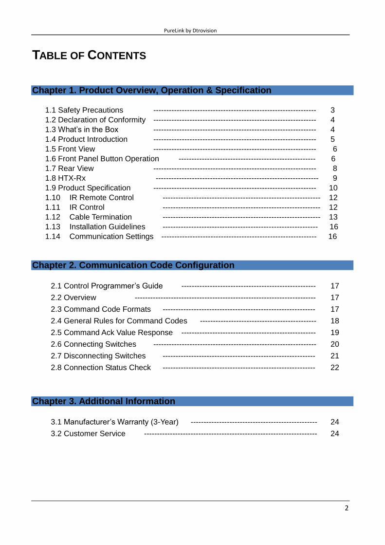
The following table shows the pinout of the RS-232 connector. DB9 cables are available with male-to-male,
female-to-female, and male-to-female connectors. HTX series matrix switcher's RS-232 port uses a female
DB9 connector and therefore requires a cable with a male connector.
Pin RS-232
1 Not used
2 Rx: Receive
3 Tx: Transmit
4 Not used
5 Ground
6 Not used
7 Not used
8 Not used
9 Not used
LAN Cable Termination (for Control)
The following table shows the pinout of the LAN connector. Note that in the pinout table, some transmit/receive
functions (abbreviated as Tx/Rx) are different for straight-through cable and crossover LAN cable.
Straight-through Cable: for connection of HTX series matrix switcher to an Ethernet network
Crossover Cable : for direct connection between the PC or controller and the HTX series
matrix switcher.
Pin
Crossover Cable
End 1 Wire Color End 2 Wire Color
1 Orange/ White Orange/ White
2 Orange Green
3 Green/ White Green/ White
4 Blue Blue
5 Blue/ White Blue/ White
6 Green Orange
7 Brown/ White Brown/ White
8 Brown Brown
Pin
Straight-through Cable
End 1 Wire Color End 2 Wire Color
1 Orange/ White Orange/ White
2 Green Green
3 Green/ White Green/ White
4 Blue Blue

PureLink by Dtrovision
16
RS-232 Cable Termination (for HTX receiver pass-thru)
3-pin Phoenix connector is used for RS-232 communication between HTX matrix switcher
and HTX receiver’s connected device.
* Pinout from the left
1.13 Installation Guidelines
The following installation settings are recommended for optimal performance.
Operational temperature should be 30° C or below
Operational humidity should be 60% or below
Operational environment should be dust-free and well ventilated
Stabilized AC input power (AVR-based power supply) is highly advised
1.14 Communication Settings (LAN and RS232)
Default RS232 communication parameters:
Baud rate: 115200
Data bit: 8 bits
Stop bit: 1 bits
Parity: none
Default LAN communication parameters:
IP address: 192.168.0.100
Mac address: 0x00,0x15,0x09,0x22,0x4c,0x87
5 Blue/ White Blue/ White
6 Orange Orange
7 Brown/ White Brown/ White
8 Brown Brown
Pin RS-232 RS-422
1 Tx Tx +
2 Ground Ground
3 Rx Rx +

PureLink by Dtrovision
17
Chapter 2. Communication Code Configuration
2.1 Control Programmer’s Guide (Code Structure and Examples)
This section is designed for programmers who wish to create their own control programs using the
command code. All PureLink digital matrix routers provide a simple character stream control used by
external control devices attached to a PureLink device. Command codes are used primarily for
control, during system installation and setup, and for diagnostic purposes.
2.2 Overview
Command code is a set of alphanumeric characters that combine to form control commands.
Command code strings are entered into a terminal emulation program (such as windows
HyperTerminal) running on an external control device. The control device (PC, third-party controller)
sends the commands to the system. Control devices must be able to send and receive ASCII or
HEXA code via an RS-232 or Ethernet port.
2.3 Command Code Formats
A command code is a series of command characters and numbers used to send commands to the
system. Commands include basic formulas for creating and disconnecting switches, as well as for
verifying the status of switches.
In a command code, each character is either general command (e.g., C for connect) or an identifier that
indicates what the following number designates (e.g., “O” and the number following it designate an “output
number”). The command code *999CI01O01! Can be interested as follows: (*) Starting the command code
(999) Router ID is 999 (C) Create connection on (I01) Input 01 to (O01) Output 01 (!) take the command. For a
complete list of command characters and their functions, see pages 16 -
Ack value (Acknowledge value: Response from Pure Link device) will be echoed back to the terminal screen
as the unit accepts them. When a command is successfully executed, all of the characters appear containing
the character “s” which stands for status. For example,
Ex 1) Command (Connect Input 1 to Output 1)
*999CI01O01!
Ack value
*999sC I01O01!
Ex 2) Command (Check Input connection status on Output 3)
*999?O03!
Ack Value
*999s? I03O03!

PureLink by Dtrovision
18
2.4 General Rules for Command Codes
The commands are coded in ASCII and HEXA. Please refer to Table 2.1 on pg. 17 for detailed
descriptions of keys and functions. A basic command code setup is shown below;
Ex) *999CI01O01!
Start (*) + Router ID (999) + Command (C) + Input number (I01) + Output
number (O01) + End (!) + Enter ( )
▶ A command line allows execution of only one command. Multiple commands require execution of
multiple strings; one command per string.
▶ All s begin with * (Start) byte.
▶ All s end with ! (End) byte.
▶ All s will be executed when (Enter) is entered.
▶ The correct Router ID must be entered in a command code. Systems will not
react to the command if a wrong Router ID is entered. The Factory Default
Router ID is set to 999 and the universal Router ID is 999. Systems will react
to the command whenever universal Router ID is entered in command code.
▶ Command codes typically are not case-sensitive.
▶ To specify multiple inputs and outputs, enter a “,” (Comma) between numbers.
(Ex., *999CI01O01,02,03! : Connects Input 01 to Output 01, 02, and 03)
▶ Use - (Hyphen) for range connection.
(EX., *999CI01O01-04! : Connects Input 01 to Output 01,02,03, and 04)

PureLink by Dtrovision
19
Table 2.1 Command Codes Characters Table
The table below shows command code characters (keys), which are used to generate control commands,
their functions, and short function descriptions.
Key Function Description and Example Byte
HEX ASCII
0x2A * Start the command Header Code 1
0x21 ! End the command Tail Code 1
Execute the command Execute the command
0x43
0x63
C
C Connect
Initiates a Connect (switch) command for Video;
this must precede input and output specification 1
0x3F ? Status Status command; this must precede input and
output specification 1
0x44
0x64
D
D Disconnect
Disconnect command for both Video and Audio;
this must precede input and output specification 1
, Space Separates the numbers within entries that
contain multiple numbers 1
- Range Specifies a range of numbers in entries
containing multiple numbers 1
?version Firmware version check Firmware version check command;
*255?version!
2.5 Command Ack (Acknowledge) Value Response
When command codes are entered into a terminal emulation program (such as HyperTerminal) and are
accepted by the system, they respond back to the terminal screen one at a time, as noted below in the
table. The complete command has executed successfully when all of the entered characters including “s”
which stands for status, appear. If a command character is not accepted, a different character than the one
entered appears and all or part of the command has not been executed.
Ack (Acknowledge) Value Response Table
The following table shows ack value response characters along with their descriptions and meanings,
which may appear instead of the initially entered character or number. If these characters appear, all or part
of the command has not been executed.
Table 3.2 Descriptions of Acknowledge (ACK) Signals
Ack value Description
Input 1 is not connected No information in each channel.
Command Code Error Indicates that system has rejected all or part of the command

PureLink by Dtrovision
20
Router ID Error Indicates that the wrong ID number was entered
Command Code Ack Value Examples
Command Code
Entered
Ack Value as appears in the control
program Explanation of Result
*999CI01O01! *255sC I01O01 ! The command was successfully executed
*999CO01! Command Code Error The command was not executed because
the input number was not included
*999CI01O01 Command Code Error The command was not executed because “!”
(End) was not included
*300CI01O01! Router ID Error
The command was not executed because
the actual Router ID and entered Router ID
did not match
2.6 Connecting Switches
A switch is an active connection between an input (source) signal and one or more output (display)
devices. The signals connected in a switch command are either individual signals or groups of signals
coming through the connectors on the rear of the unit.
The “C” key initiates a Connect command for routing a switch. The characters and numbers that follow the “C”
command tell the system, which inputs and outputs to connect. The last character “!” is found at the end of a
command code which tells the system to execute the command.
For example, the command code *999CI01O01!
can be interpreted as follows: (*) Starting the command code (999) Router ID is 999 (C) Create connection on
(I01) Input 01 to (O01) Output 01 (!) take the command. For a complete list of command characters and their
functions, see examples below.
To connect a switch:
1. Enter the Connect command below. Replace the “#”s with the input and output number(s).
*999CI#O#!
Examples (Connect) :
Command Codes Action
*999CI01O01! Connect Input 1 to Output 1
*999CI01O04,I04O02! Connect Input 1 to Output 4 and Input 4 to Output 2
*999CI01O01,I02O02,I03O03! Connect Input 1 to Output 1, Input 2 to Output 2, and Input 3 to Output 3
*999CI01O01,02,03! Connect Input 1 to Output 1, 2, and 3

PureLink by Dtrovision
21
*999CI01O01-04! Connect Input 1 to Output 1, 2, 3, and 4
*999PTP! Connect Input 1 to Output 1, Input 2 to Output 2, Input 3 to Output 3 and Input 4 to
Output 4
2.7 Disconnecting Switches
The characters and numbers in a Disconnect command tell the system which input or output to
disconnect. The “D” key initiates a Disconnect command for routing a switch. The characters and
numbers that follow the “D” command tell the system that inputs and outputs to disconnect. The last
character “!” is found at the end of the Command code, which tells the system to execute the
command.
For example, the command code
*999DI01O00!
It can be interpreted as follows: (*) Starting the command code (999) Router ID is 999 (D) Disconnect on (I01)
Input 01 to (O00) Output 00 (!) take the command. For a complete list of command characters and their
functions, see the command list below
1. Enter the Disconnect command below. Replace the “#”s with the input and output number(s).
*999DI#O#!
Examples (Disconnect) :
Command Codes Action
*999DI01O00! Disconnect Input 1 to no Output (00)
*999DI00O03,04! Disconnects Outputs 3, and 4
*999DI00O03-04! Disconnects output 3, and 4
*999DALLIO! Disconnects all inputs and outputs
EDID Setting
*999EDIDI01E3!
: write E3 EDID (1080p, HD audio) to input # 1
List of EDID
E1 1080p, 2 ch audio E2 1080p, dolby/dts 5.1 E3 1080p, HD audio
E4 1080i, 2 ch audio E5 1080i, dolby/dts 5.1 E6 1080i, HD audio
E7 3D, 1080p, 2 ch audio E8 3D, 1080p, dolby/dts 5.1 E9 3D, 1080p, HD audio
E10 4K@30Hz, 2 ch audio E11 4K@30Hz, dolby/dts 5.1 E12 4K@30Hz, HD audio
E13 4K@60Hz, 2 ch audio E14 4K@60Hz, dolby/dts 5.1 E15 4K@60Hz, HD audio
E16 Emulate from HDMI output #1 E17 Emulate from HDMI output #2 E18 Emulate from HDMI output #3

PureLink by Dtrovision
22
E19 Emulate from HDMI output #4 E20 Emulate from HDBT output #1 E21 Emulate from HDBT output #2
E22 Emulate from HDBT output #3 E23 Emulate from HDBT output #4
Beep On
*999BeepON!
Beep Off
*999BeepOFF!
Front panel buttons Lock On
*999lockon!
Front panel buttons Lock Off
*999lockoff!
Power on
*999poweron!
Power off
*999poweroff!
Factory setting restore
*999restore!
Reboot
*999reboot!
2.8 Status Check
A connection status can be checked to confirm that the switch has been correctly executed or to
confirm correct routing to multiple outputs. The characters and numbers in a status command tell the
system which input or output to check.
1. Enter the Connection status check command below. Replace the “#”s with the input and output
number(s).
*999?I#! or *255?O#!
Examples:
Command Codes Action
*999?I01! Check Output connection status on Input 1

PureLink by Dtrovision
23
*999?O04! Check Input connection status on Output 4
*999?ALLIO! Check all Input and Output connection status
Input EDID status
*999?EDIDi01!
I01 = input 1 i02 = input 2 i03 = input 3 i04 = input 4
Firmware version check
*999?version!

PureLink by Dtrovision
24
Chapter 3. Additional Information
3.1 Manufacturer’s Warranty (3-Years)
PureLink warrants this HTX series matrix switcher to be free from defects in workmanship and materials,
under normal use and service, for a period of three (3) year from the date of purchase from PureLink or its
authorized resellers.
If the product does not operate as warranted during the applicable warranty period, PureLink shall, at its
option and expense, execute one of the following as necessary:
1. Repair the defective product or part
2. Deliver to customer and equivalent product or part to replace the defective item
3. Refund to customer the purchase price paid for the defective product
All products that are replaced become the property of PureLink. Replacement products may be new or
reconditioned. Repaired or replacement products or parts come with a 90-day warranty or the remainder
of the warranty period. Dtrovision shall not be responsible for any software, firmware, information, or
memory data loss of contained in, stored on, or integrated with any products returned to Dtrovision for
repair under warranty.
3.2 Customer Service
Any customer service inquiries can be submitted electronically through the Q&A form on our website
( www.purelinkav.com ).
For immediate assistance please contact us at (201) 488-3232 to reach our customer care or tech support
team.


![[Bs 8800]-british standard-8800-1996[1]](https://img.pdfslide.net/doc/110x75/5587f770d8b42a03178b46e0/bs-8800-british-standard-8800-19961.jpg)