Embed Size (px)
Citation preview
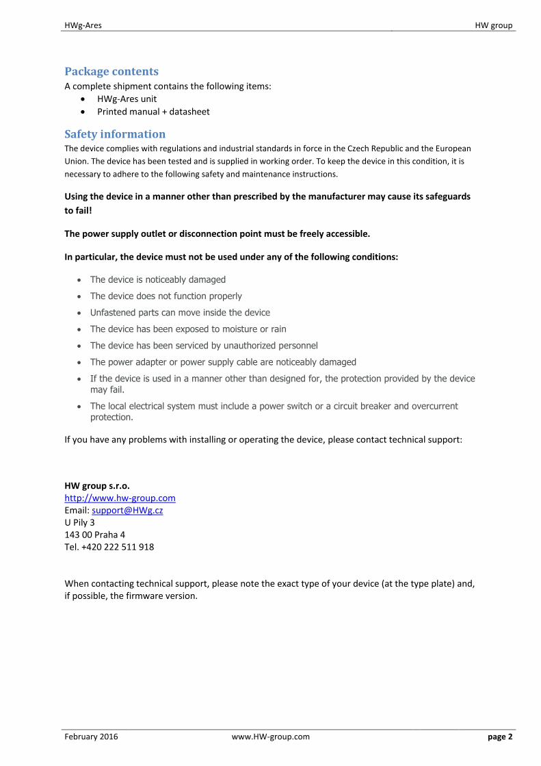
HWg-Ares 12/14
MANUAL
HWg-Ares HW group
February 2016 www.HW-group.com page 2
Package contents A complete shipment contains the following items:
HWg-Ares unit
Printed manual + datasheet
Safety information The device complies with regulations and industrial standards in force in the Czech Republic and the European
Union. The device has been tested and is supplied in working order. To keep the device in this condition, it is
necessary to adhere to the following safety and maintenance instructions.
Using the device in a manner other than prescribed by the manufacturer may cause its safeguards
to fail!
The power supply outlet or disconnection point must be freely accessible.
In particular, the device must not be used under any of the following conditions:
The device is noticeably damaged
The device does not function properly
Unfastened parts can move inside the device
The device has been exposed to moisture or rain
The device has been serviced by unauthorized personnel
The power adapter or power supply cable are noticeably damaged
If the device is used in a manner other than designed for, the protection provided by the device
may fail.
The local electrical system must include a power switch or a circuit breaker and overcurrent
protection.
If you have any problems with installing or operating the device, please contact technical support:
HW group s.r.o. http://www.hw-group.com Email: [email protected] U Pily 3 143 00 Praha 4 Tel. +420 222 511 918 When contacting technical support, please note the exact type of your device (at the type plate) and, if possible, the firmware version.
HWg-Ares HW group
February 2016 www.HW-group.com page 3
Table of Contents Package contents................................................................................................................................. 2
Safety information ............................................................................................................................... 2
Basic features ...................................................................................................................................... 4
Description of connectors and connections ........................................................................................ 5
First steps ............................................................................................................................................ 8
Digital Inputs tab ........................................................................................................................... 10
Sensors tab .................................................................................................................................... 11
SMS tab .......................................................................................................................................... 12
E-mail tab....................................................................................................................................... 13
Advanced settings ............................................................................................................................. 14
General tab .................................................................................................................................... 14
Digital Inputs tab ........................................................................................................................... 16
Sensors tab .................................................................................................................................... 17
Time tab ......................................................................................................................................... 18
SMS tab .......................................................................................................................................... 19
SMS Template tab ......................................................................................................................... 20
E-mail tab....................................................................................................................................... 22
Email Template tab........................................................................................................................ 23
GSM/GRPS/Internet tab ................................................................................................................ 24
Portal ............................................................................................................................................. 25
Logger ............................................................................................................................................ 28
System ........................................................................................................................................... 29
How to reduce operating costs ......................................................................................................... 30
Primary cost-saving options .......................................................................................................... 35
Special functions ............................................................................................................................... 35
Text message commands .................................................................................................................. 35
Troubleshooting ................................................................................................................................ 36
Internal memory size ......................................................................................................................... 37
1-Wire UNI sensors ............................................................................................................................ 37
Customizing user messages ............................................................................................................... 38
Mechanical ........................................................................................................................................ 41
HWg-Ares HW group
February 2016 www.HW-group.com page 4
Basic features
Quadband modem GSM 850 / 900 / 1800 / 1900 MHz
Number of 1-Wire sensors:
o Ares 12 – 3
o Ares 14 – 14
External antenna
Support for PIN-protected SIM
Alarm alerts
o SMS (up to 5 phone numbers)
o Ringing a specified number (up to 5 phone numbers)
o Email (up to 5 addresses) with selectable priority
User templates for SMS and Email alarms (different for each sensor)
Periodic reminders about active alarms
Per-sensor hysteresis settings
Logs periodically e-mailed to up to 5 addresses (independent from Alarm addresses) with
selectable priority
Configurable global interval for storing measured values (15 minutes by default)
Support for portal-based solutions with the HWg-PUSH protocol
o Periodic data transfer
o Data transfer when values differ by more than the specified tolerance
Status request
o SMS from a predefined number
o SMS from any number containing a password
o Ringing the device from a predefined number
Internal memory for measured values: 2 MB – 170,000 records
Simple configuration with an intuitive Windows utility
Connects to PC over USB without special drivers (Mass Storage, HID)
Power failure indication through a virtual input (supports alarms)
Battery status indication (supports alarms)
Option to activate/deactivate GPRS when roaming. SMS alarms and control still 100%
functional
Wall mount, DIN rail mount options
Firmware upgrade over USB or GPRS (On the Fly – Over the Air)
o Upgrade can be started with a SMS command
Logging stops when Ares is connected to USB
Sensors are automatically detected when the device is turned on
Alarm information available immediately after powering up
HWg-Ares HW group
February 2016 www.HW-group.com page 5
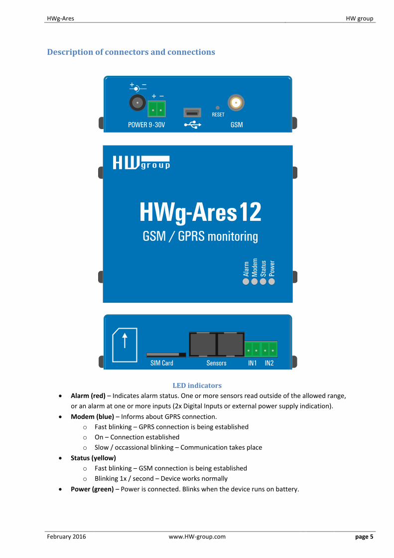
Description of connectors and connections
LED indicators
Alarm (red) – Indicates alarm status. One or more sensors read outside of the allowed range,
or an alarm at one or more inputs (2x Digital Inputs or external power supply indication).
Modem (blue) – Informs about GPRS connection.
o Fast blinking – GPRS connection is being established
o On – Connection established
o Slow / occassional blinking – Communication takes place
Status (yellow)
o Fast blinking – GSM connection is being established
o Blinking 1x / second – Device works normally
Power (green) – Power is connected. Blinks when the device runs on battery.

HWg-Ares HW group
February 2016 www.HW-group.com page 6
Inputs
2x Digital Input for connecting a voltage-free (dry) contact. Logic LOW (contact open) when the
resistance between terminals is greater than 15 kOhm. Logic HIGH (closed contact) when the
resistance is less than 2.7 kOhm. Resistances between these values are undefined.
Power
Power supply 9-30V/500mA can be connected to the power terminals or the power barrel connector.
The terminals and the connector are interconnected and can NOT be used to connect two different
power sources (e.g. adapter and back-up battery).
Sensors
2x independent port for connecting 1-Wire sensors, with support for 1-Wire UNI. Each port can be
connected to a bus, maximum length is 60 m. The total number of supported sensors is a device-
wide limitation, the sensors can be connected to one port or distributed among both ports in any
way.
Caution: There is a limit of two 1-Wire UNI sensors per port. Some 1-Wire UNI sensors may require an
active hub – see 1-Wire UNI sensors.
Sim Card
Standard plug-in SIM
GSM
SMA connector for an external antenna. The external antenna needs to be QuadBand-capable and
equipped with a male SMA connector. External antenna is required for proper operation of the
device.
HWg-Ares HW group
February 2016 www.HW-group.com page 7
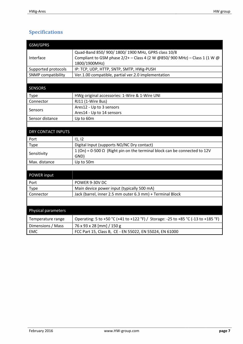
Specifications
GSM/GPRS
Interface Quad-Band 850/ 900/ 1800/ 1900 MHz, GPRS class 10/8 Compliant to GSM phase 2/2+ – Class 4 (2 W @850/ 900 MHz) – Class 1 (1 W @ 1800/1900MHz)
Supported protocols IP: TCP, UDP, HTTP, SNTP, SMTP, HWg-PUSH
SNMP compatibility Ver.1.00 compatible, partial ver.2.0 implementation
SENSORS
Type HWg original accessories: 1-Wire & 1-Wire UNI
Connector RJ11 (1-Wire Bus)
Sensors Ares12 - Up to 3 sensors Ares14 - Up to 14 sensors
Sensor distance Up to 60m
DRY CONTACT INPUTS
Port I1, I2
Type Digital Input (supports NO/NC Dry contact)
Sensitivity 1 (On) = 0-500 Ω (Right pin on the terminal block can be connected to 12V GND)
Max. distance Up to 50m
POWER input
Port POWER 9-30V DC
Type Main device power input (typically 500 mA)
Connector Jack (barrel, inner 2.5 mm outer 6.3 mm) + Terminal Block
Physical parameters
Temperature range Operating: 5 to +50 °C (+41 to +122 °F) / Storage: -25 to +85 °C (-13 to +185 °F)
Dimensions / Mass 76 x 93 x 28 [mm] / 150 g
EMC FCC Part 15, Class B, CE - EN 55022, EN 55024, EN 61000
HWg-Ares HW group
February 2016 www.HW-group.com page 8
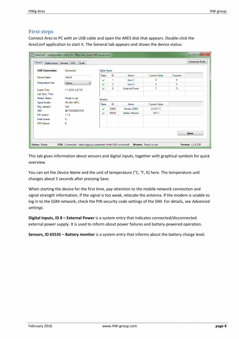
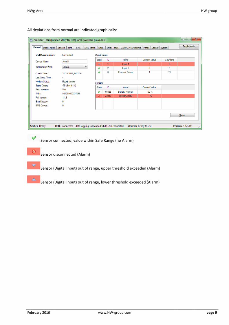
First steps Connect Ares to PC with an USB cable and open the ARES disk that appears. Double-click the
AresConf application to start it. The General tab appears and shows the device status:
This tab gives information about sensors and digital inputs, together with graphical symbols for quick
overview.
You can set the Device Name and the unit of temperature (°C, °F, K) here. The temperature unit
changes about 5 seconds after pressing Save.
When starting the device for the first time, pay attention to the mobile network connection and
signal strength information. If the signal is too weak, relocate the antenna. If the modem is unable to
log in to the GSM network, check the PIN security code settings of the SIM. For details, see Advanced
settings.
Digital Inputs, ID 8 – External Power is a system entry that indicates connected/disconnected
external power supply. It is used to inform about power failures and battery-powered operation.
Sensors, ID 65535 – Battery monitor is a system entry that informs about the battery charge level.
HWg-Ares HW group
February 2016 www.HW-group.com page 9
All deviations from normal are indicated graphically:
Sensor connected, value within Safe Range (no Alarm)
Sensor disconnected (Alarm)
Sensor (Digital Input) out of range, upper threshold exceeded (Alarm)
Sensor (Digital Input) out of range, lower threshold exceeded (Alarm)
HWg-Ares HW group
February 2016 www.HW-group.com page 10
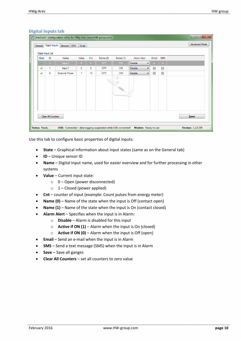
Digital Inputs tab
Use this tab to configure basic properties of digital inputs:
State – Graphical information about input states (same as on the General tab)
ID – Unique sensor ID
Name – Digital Input name, used for easier overview and for further processing in other
systems
Value – Current input state:
o 0 – Open (power disconnected)
o 1 – Closed (power applied)
Cnt – counter of input (example: Count pulses from energy meter)
Name (0) – Name of the state when the input is Off (contact open)
Name (1) – Name of the state when the input is On (contact closed)
Alarm Alert – Specifies when the input is in Alarm:
o Disable – Alarm is disabled for this input
o Active if ON (1) – Alarm when the input is On (closed)
o Active if ON (0) – Alarm when the input is Off (open)
Email – Send an e-mail when the input is in Alarm
SMS – Send a text message (SMS) when the input is in Alarm
Save – Save all ganges
Clear All Counters – set all counters to zero value
HWg-Ares HW group
February 2016 www.HW-group.com page 11
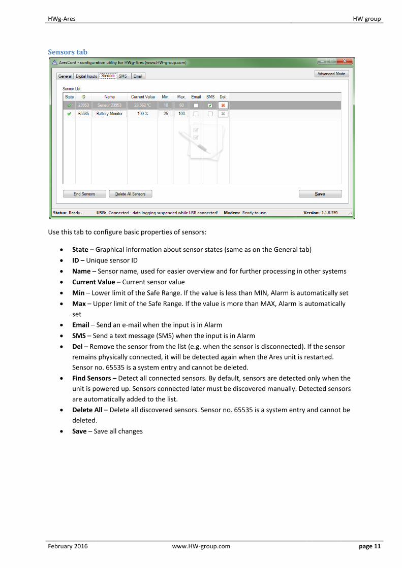
Sensors tab
Use this tab to configure basic properties of sensors:
State – Graphical information about sensor states (same as on the General tab)
ID – Unique sensor ID
Name – Sensor name, used for easier overview and for further processing in other systems
Current Value – Current sensor value
Min – Lower limit of the Safe Range. If the value is less than MIN, Alarm is automatically set
Max – Upper limit of the Safe Range. If the value is more than MAX, Alarm is automatically
set
Email – Send an e-mail when the input is in Alarm
SMS – Send a text message (SMS) when the input is in Alarm
Del – Remove the sensor from the list (e.g. when the sensor is disconnected). If the sensor
remains physically connected, it will be detected again when the Ares unit is restarted.
Sensor no. 65535 is a system entry and cannot be deleted.
Find Sensors – Detect all connected sensors. By default, sensors are detected only when the
unit is powered up. Sensors connected later must be discovered manually. Detected sensors
are automatically added to the list.
Delete All – Delete all discovered sensors. Sensor no. 65535 is a system entry and cannot be
deleted.
Save – Save all changes
HWg-Ares HW group
February 2016 www.HW-group.com page 12
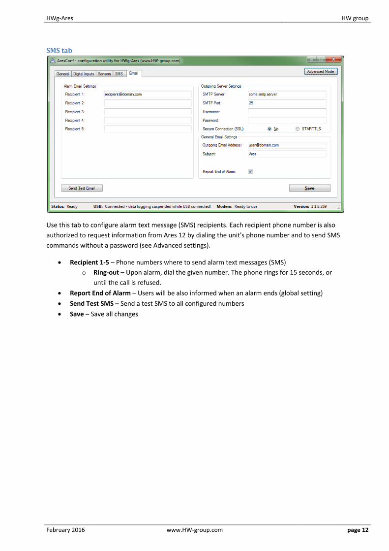
SMS tab
Use this tab to configure alarm text message (SMS) recipients. Each recipient phone number is also
authorized to request information from Ares 12 by dialing the unit's phone number and to send SMS
commands without a password (see Advanced settings).
Recipient 1-5 – Phone numbers where to send alarm text messages (SMS)
o Ring-out – Upon alarm, dial the given number. The phone rings for 15 seconds, or
until the call is refused.
Report End of Alarm – Users will be also informed when an alarm ends (global setting)
Send Test SMS – Send a test SMS to all configured numbers
Save – Save all changes

HWg-Ares HW group
February 2016 www.HW-group.com page 13
E-mail tab
Use this tab to configure alarm e-mail recipients and parameters.
Recipient 1-5 – Addresses of recipients for alarm e-mails
Report End of Alarm – Users will be also informed when an alarm ends (global setting)
SMTP Server* – IP address or host name of the SMTP server to use for sending e-mail
SMTP Port* – TCP port where the SMTP server listens
Username* – Username for authentication to the SMTP server
Password* – Password for authentication to the SMTP server
Show Password – Display the actual password instead of asterisks
Secure Connection (SSL)*: No/STARTTLS – Enables encrypted authentication
Outgoing Email Address – Sender e-mail address. E-mails will be sent to the recipients from
this address.
Subject – Subject prefix. Useful for adding a keyword to the e-mail subject in order to
simplify mail filtering.
Send Test Email – Send a test e-mail to all listed recipients
Save – Save all changes
*Ask your network administrator or mobile carrier for this information.
HWg-Ares HW group
February 2016 www.HW-group.com page 14
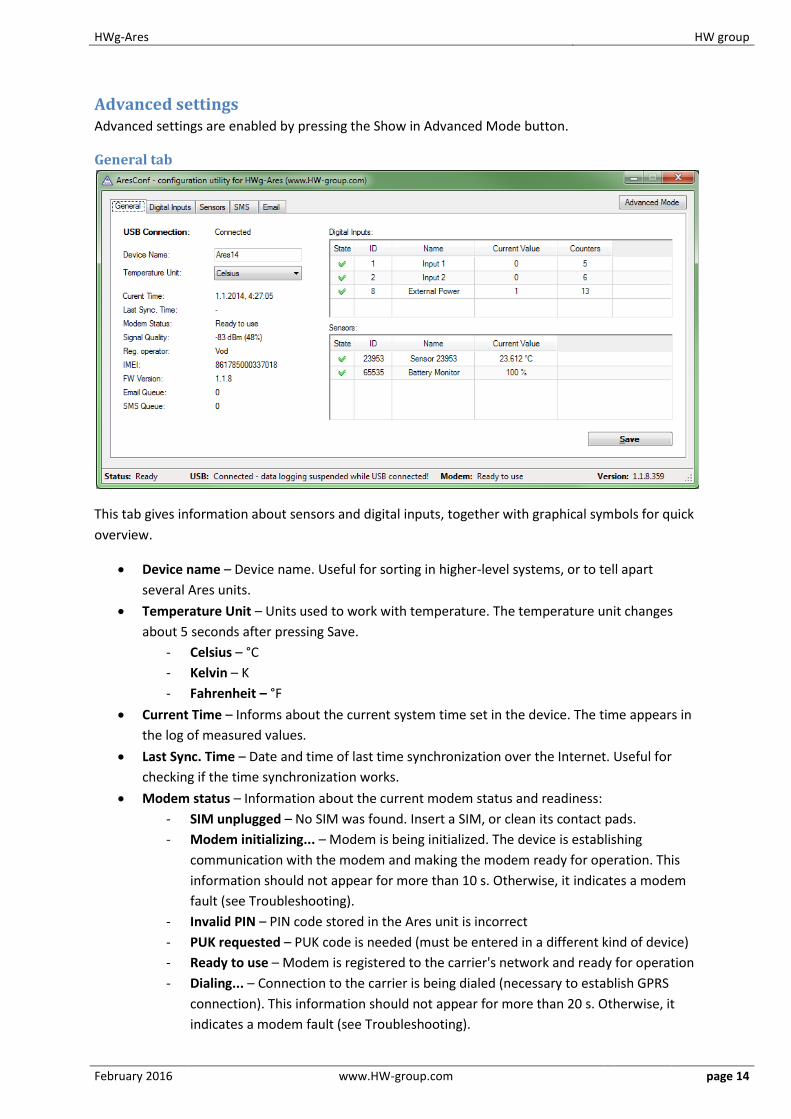
Advanced settings Advanced settings are enabled by pressing the Show in Advanced Mode button.
General tab
This tab gives information about sensors and digital inputs, together with graphical symbols for quick
overview.
Device name – Device name. Useful for sorting in higher-level systems, or to tell apart
several Ares units.
Temperature Unit – Units used to work with temperature. The temperature unit changes
about 5 seconds after pressing Save.
- Celsius – °C
- Kelvin – K
- Fahrenheit – °F
Current Time – Informs about the current system time set in the device. The time appears in
the log of measured values.
Last Sync. Time – Date and time of last time synchronization over the Internet. Useful for
checking if the time synchronization works.
Modem status – Information about the current modem status and readiness:
- SIM unplugged – No SIM was found. Insert a SIM, or clean its contact pads.
- Modem initializing... – Modem is being initialized. The device is establishing
communication with the modem and making the modem ready for operation. This
information should not appear for more than 10 s. Otherwise, it indicates a modem
fault (see Troubleshooting).
- Invalid PIN – PIN code stored in the Ares unit is incorrect
- PUK requested – PUK code is needed (must be entered in a different kind of device)
- Ready to use – Modem is registered to the carrier's network and ready for operation
- Dialing... – Connection to the carrier is being dialed (necessary to establish GPRS
connection). This information should not appear for more than 20 s. Otherwise, it
indicates a modem fault (see Troubleshooting).
HWg-Ares HW group
February 2016 www.HW-group.com page 15
- Configuring Internet... – Internet connection is being configured (reading IP
parameters)
- Connected to Internet – The modem is successfully connected to the Internet
- Terminating Internet... – Internet connection is being disconnected
- Terminate – Connection to the mobile network was terminated. This can appear
when the device is being restarted, switched off, or when its battery is low.
- Hanging... – Dial-up connection is being hanged up
- - – Unknown state
Signal Quality – GSM signal quality in dBm and as a percentage. The percentage should be as
high as possible. If it is less than 50%, we strongly suggest to relocate the antenna or use a
different mobile carrier.
Reg. Operator – Regional GSM carrier. Indicates a successful connection to the GSM
network, and the actual carrier when roaming.
FW version – Current firmware version
Email Queue – Number of outgoing e-mails waiting in the queue
SMS Queue – Number of outgoing text messages waiting in the queue
Digital Inputs, ID 8 – External Power is a system entry that indicates connected/disconnected
external power supply. It is used to inform about power failures and battery-powered operation.
Sensors, ID 65535 – Battery monitor is a system entry that informs about the battery charge level.
HWg-Ares HW group
February 2016 www.HW-group.com page 16
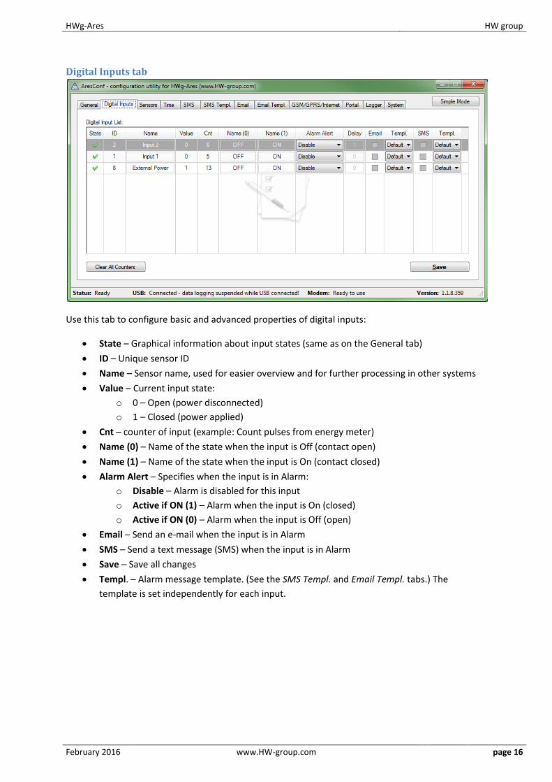
Digital Inputs tab
Use this tab to configure basic and advanced properties of digital inputs:
State – Graphical information about input states (same as on the General tab)
ID – Unique sensor ID
Name – Sensor name, used for easier overview and for further processing in other systems
Value – Current input state:
o 0 – Open (power disconnected)
o 1 – Closed (power applied)
Cnt – counter of input (example: Count pulses from energy meter)
Name (0) – Name of the state when the input is Off (contact open)
Name (1) – Name of the state when the input is On (contact closed)
Alarm Alert – Specifies when the input is in Alarm:
o Disable – Alarm is disabled for this input
o Active if ON (1) – Alarm when the input is On (closed)
o Active if ON (0) – Alarm when the input is Off (open)
Email – Send an e-mail when the input is in Alarm
SMS – Send a text message (SMS) when the input is in Alarm
Save – Save all changes
Templ. – Alarm message template. (See the SMS Templ. and Email Templ. tabs.) The
template is set independently for each input.
HWg-Ares HW group
February 2016 www.HW-group.com page 17
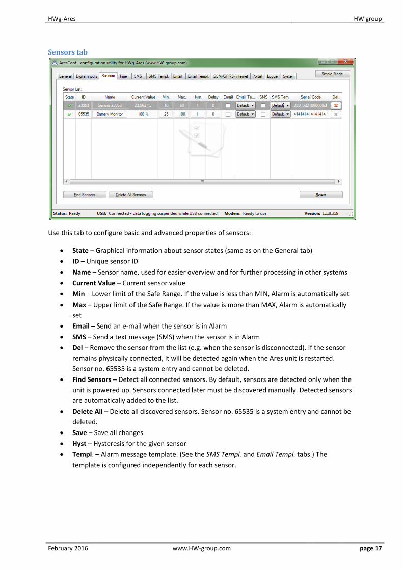
Sensors tab
Use this tab to configure basic and advanced properties of sensors:
State – Graphical information about sensor states (same as on the General tab)
ID – Unique sensor ID
Name – Sensor name, used for easier overview and for further processing in other systems
Current Value – Current sensor value
Min – Lower limit of the Safe Range. If the value is less than MIN, Alarm is automatically set
Max – Upper limit of the Safe Range. If the value is more than MAX, Alarm is automatically
set
Email – Send an e-mail when the sensor is in Alarm
SMS – Send a text message (SMS) when the sensor is in Alarm
Del – Remove the sensor from the list (e.g. when the sensor is disconnected). If the sensor
remains physically connected, it will be detected again when the Ares unit is restarted.
Sensor no. 65535 is a system entry and cannot be deleted.
Find Sensors – Detect all connected sensors. By default, sensors are detected only when the
unit is powered up. Sensors connected later must be discovered manually. Detected sensors
are automatically added to the list.
Delete All – Delete all discovered sensors. Sensor no. 65535 is a system entry and cannot be
deleted.
Save – Save all changes
Hyst – Hysteresis for the given sensor
Templ. – Alarm message template. (See the SMS Templ. and Email Templ. tabs.) The
template is configured independently for each sensor.
HWg-Ares HW group
February 2016 www.HW-group.com page 18
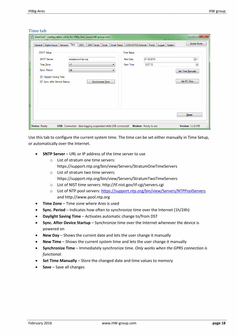
Time tab
Use this tab to configure the current system time. The time can be set either manually in Time Setup,
or automatically over the Internet.
SNTP Server – URL or IP address of the time server to use
o List of stratum one time servers:
https://support.ntp.org/bin/view/Servers/StratumOneTimeServers
o List of stratum two time servers:
https://support.ntp.org/bin/view/Servers/StratumTwoTimeServers
o List of NIST time servers: http://tf.nist.gov/tf-cgi/servers.cgi
o List of NTP pool servers: https://support.ntp.org/bin/view/Servers/NTPPoolServers
and http://www.pool.ntp.org
Time Zone – Time zone where Ares is used
Sync. Period – Indicates how often to synchronize time over the Internet (1h/24h)
Daylight Saving Time – Activates automatic change to/from DST
Sync. After Device Startup – Synchronize time over the Internet whenever the device is
powered on
New Day – Shows the current date and lets the user change it manually
New Time – Shows the current system time and lets the user change it manually
Synchronize Time – Immediately synchronize time. Only works when the GPRS connection is
functional.
Set Time Manually – Store the changed date and time values to memory
Save – Save all changes
HWg-Ares HW group
February 2016 www.HW-group.com page 19
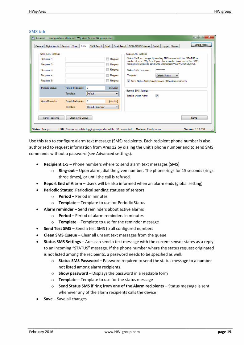
SMS tab
Use this tab to configure alarm text message (SMS) recipients. Each recipient phone number is also
authorized to request information from Ares 12 by dialing the unit's phone number and to send SMS
commands without a password (see Advanced settings).
Recipient 1-5 – Phone numbers where to send alarm text messages (SMS)
o Ring-out – Upon alarm, dial the given number. The phone rings for 15 seconds (rings
three times), or until the call is refused.
Report End of Alarm – Users will be also informed when an alarm ends (global setting)
Periodic Status: Periodical sending statuses of sensors
o Period – Period in minutes
o Template – Template to use for Periodic Status
Alarm reminder – Send reminders about active alarms
o Period – Period of alarm reminders in minutes
o Template – Template to use for the reminder message
Send Test SMS – Send a test SMS to all configured numbers
Clean SMS Queue – Clear all unsent text messages from the queue
Status SMS Settings – Ares can send a text message with the current sensor states as a reply
to an incoming “STATUS” message. If the phone number where the status request originated
is not listed among the recipients, a password needs to be specified as well.
o Status SMS Password – Password required to send the status message to a number
not listed among alarm recipients.
o Show password – Displays the password in a readable form
o Template – Template to use for the status message
o Send Status SMS if ring from one of the Alarm recipients – Status message is sent
whenever any of the alarm recipients calls the device
Save – Save all changes
HWg-Ares HW group
February 2016 www.HW-group.com page 20
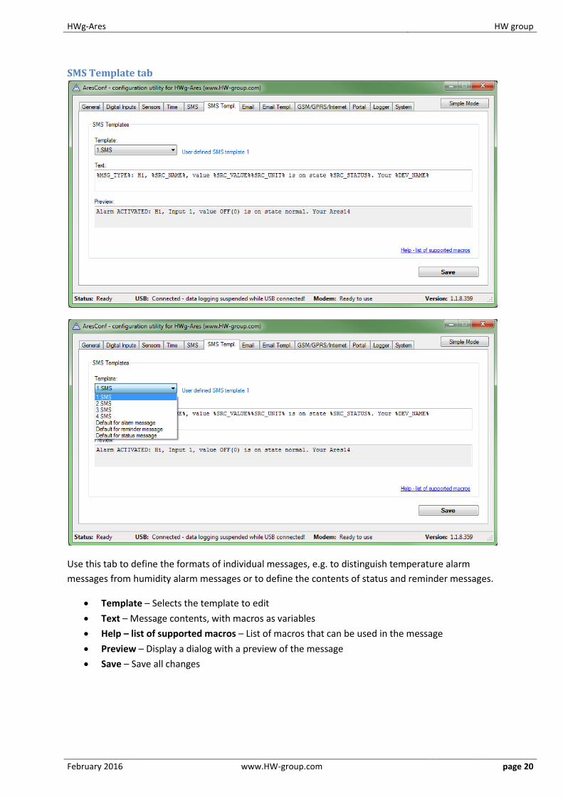
SMS Template tab
Use this tab to define the formats of individual messages, e.g. to distinguish temperature alarm
messages from humidity alarm messages or to define the contents of status and reminder messages.
Template – Selects the template to edit
Text – Message contents, with macros as variables
Help – list of supported macros – List of macros that can be used in the message
Preview – Display a dialog with a preview of the message
Save – Save all changes

HWg-Ares HW group
February 2016 www.HW-group.com page 21
Macros window
HWg-Ares HW group
February 2016 www.HW-group.com page 22
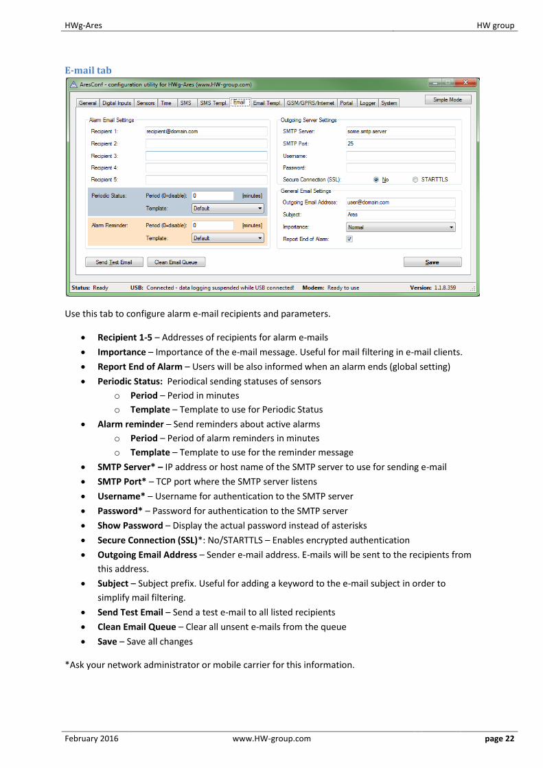
E-mail tab
Use this tab to configure alarm e-mail recipients and parameters.
Recipient 1-5 – Addresses of recipients for alarm e-mails
Importance – Importance of the e-mail message. Useful for mail filtering in e-mail clients.
Report End of Alarm – Users will be also informed when an alarm ends (global setting)
Periodic Status: Periodical sending statuses of sensors
o Period – Period in minutes
o Template – Template to use for Periodic Status
Alarm reminder – Send reminders about active alarms
o Period – Period of alarm reminders in minutes
o Template – Template to use for the reminder message
SMTP Server* – IP address or host name of the SMTP server to use for sending e-mail
SMTP Port* – TCP port where the SMTP server listens
Username* – Username for authentication to the SMTP server
Password* – Password for authentication to the SMTP server
Show Password – Display the actual password instead of asterisks
Secure Connection (SSL)*: No/STARTTLS – Enables encrypted authentication
Outgoing Email Address – Sender e-mail address. E-mails will be sent to the recipients from
this address.
Subject – Subject prefix. Useful for adding a keyword to the e-mail subject in order to
simplify mail filtering.
Send Test Email – Send a test e-mail to all listed recipients
Clean Email Queue – Clear all unsent e-mails from the queue
Save – Save all changes
*Ask your network administrator or mobile carrier for this information.
HWg-Ares HW group
February 2016 www.HW-group.com page 23
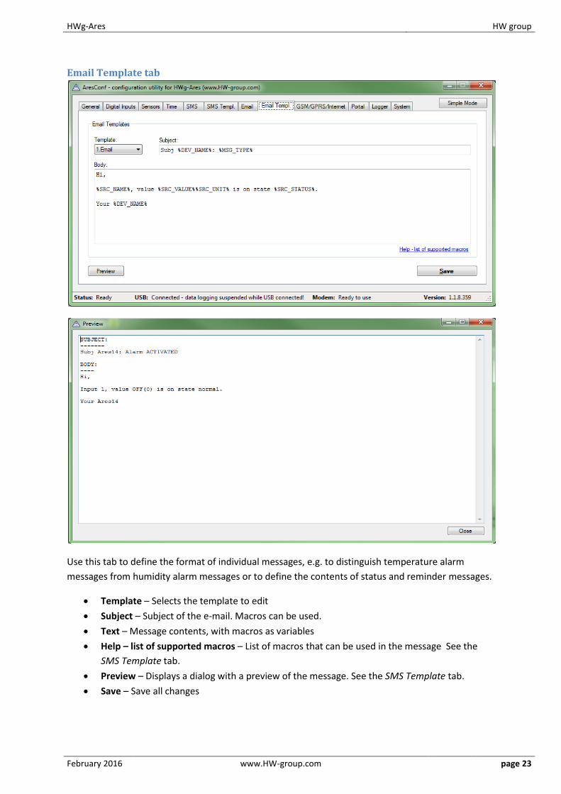
Email Template tab
Use this tab to define the format of individual messages, e.g. to distinguish temperature alarm
messages from humidity alarm messages or to define the contents of status and reminder messages.
Template – Selects the template to edit
Subject – Subject of the e-mail. Macros can be used.
Text – Message contents, with macros as variables
Help – list of supported macros – List of macros that can be used in the message See the
SMS Template tab.
Preview – Displays a dialog with a preview of the message. See the SMS Template tab.
Save – Save all changes

HWg-Ares HW group
February 2016 www.HW-group.com page 24
GSM/GRPS/Internet tab
Use this tab to configure the GSM and Internet connection details.
SIM Card PIN – Specifies the security PIN code for the SIM. The SIM can remain protected
with the PIN.
Show Password – Display the entered PIN
Enable GPRS/Internet – Enable Internet-based services, such as sending e-mail, portal
services and time synchronization
GPRS Operator Settings – Settings for accessing the GPRS network of the mobile carrier:
o APN Address – Access Point Name identifier. The default is “internet”. Your mobile
carrier can advise if another is needed.
o Dial Number – Phone number for accessing the Internet. The default is *99***1#.
Your mobile carrier can advise if another is needed.
Roaming – Enable Internet connection outside of the home carrier network, e.g. when
traveling abroad
Show Advanced GPRS Settings – Display advanced settings that are accessible directly using
AT commands (for experts only)
Username – User name for the connection. Will be provided by the mobile carrier if needed.
Password – Password for the connection. Will be provided by the mobile carrier if needed.
Dialup String – AT string. Will be provided by the mobile carrier if needed.
Save – Save all changes

HWg-Ares HW group
February 2016 www.HW-group.com page 25
Portal
Use this tab to configure the HWg-PUSH protocol.
Enable Portal – Enable transmission of data to a remote portal (HWg-PDMS etc.)
Server Address – HTTP address of the portal where the data should be sent
Port – TCP port of the remote portal (default 80)
Username – Username for authentication to the portal
Password – Password for authentication to the portal
Manual Push – Manual transmission for test purposes
Save – Save all changes
HWg-Ares HW group
February 2016 www.HW-group.com page 26
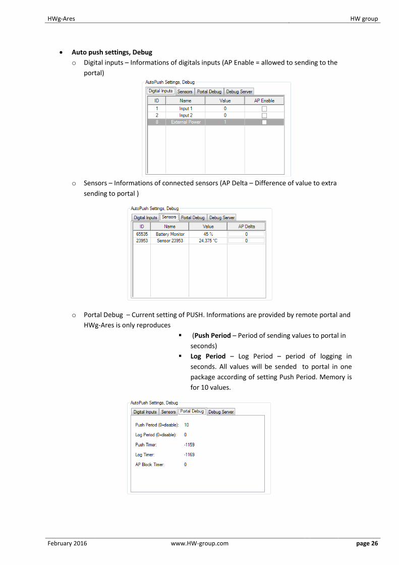
Auto push settings, Debug
o Digital inputs – Informations of digitals inputs (AP Enable = allowed to sending to the
portal)
o Sensors – Informations of connected sensors (AP Delta – Difference of value to extra
sending to portal )
o Portal Debug – Current setting of PUSH. Informations are provided by remote portal and
HWg-Ares is only reproduces
(Push Period – Period of sending values to portal in
seconds)
Log Period – Log Period – period of logging in
seconds. All values will be sended to portal in one
package according of setting Push Period. Memory is
for 10 values.
HWg-Ares HW group
February 2016 www.HW-group.com page 27
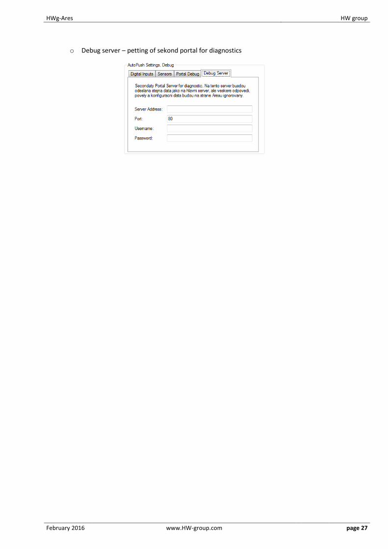
o Debug server – petting of sekond portal for diagnostics
HWg-Ares HW group
February 2016 www.HW-group.com page 28
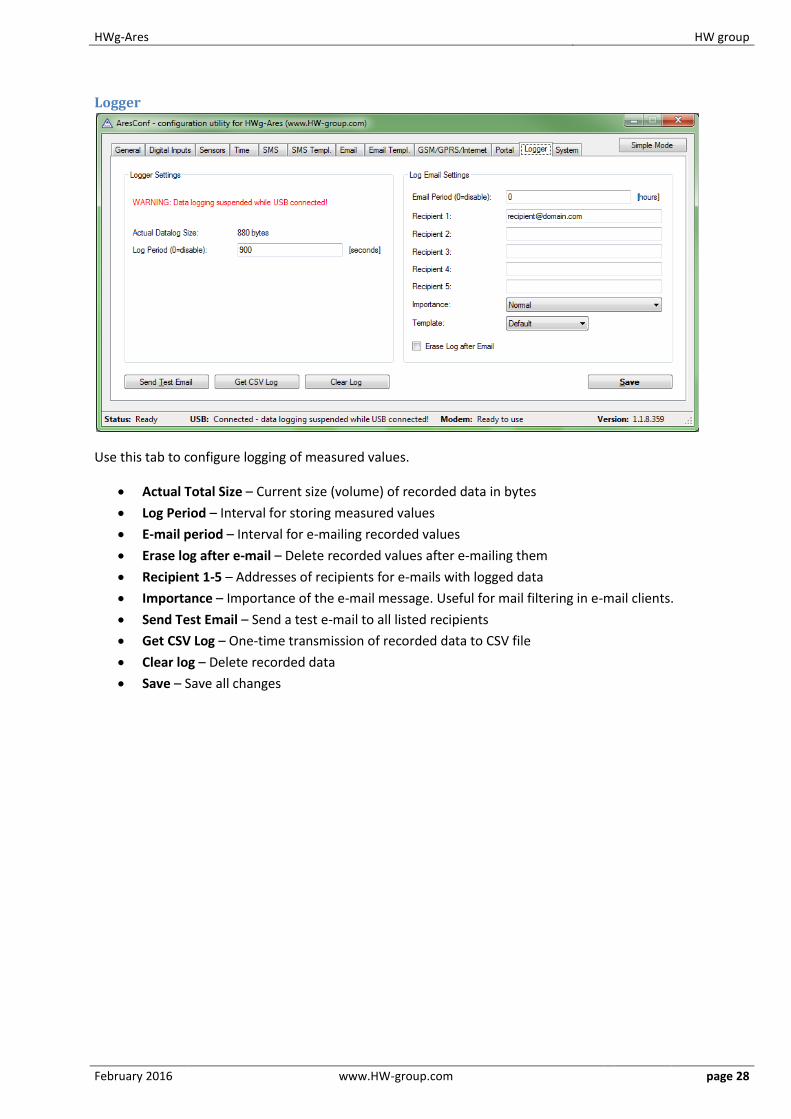
Logger
Use this tab to configure logging of measured values.
Actual Total Size – Current size (volume) of recorded data in bytes
Log Period – Interval for storing measured values
E-mail period – Interval for e-mailing recorded values
Erase log after e-mail – Delete recorded values after e-mailing them
Recipient 1-5 – Addresses of recipients for e-mails with logged data
Importance – Importance of the e-mail message. Useful for mail filtering in e-mail clients.
Send Test Email – Send a test e-mail to all listed recipients
Get CSV Log – One-time transmission of recorded data to CSV file
Clear log – Delete recorded data
Save – Save all changes
HWg-Ares HW group
February 2016 www.HW-group.com page 29
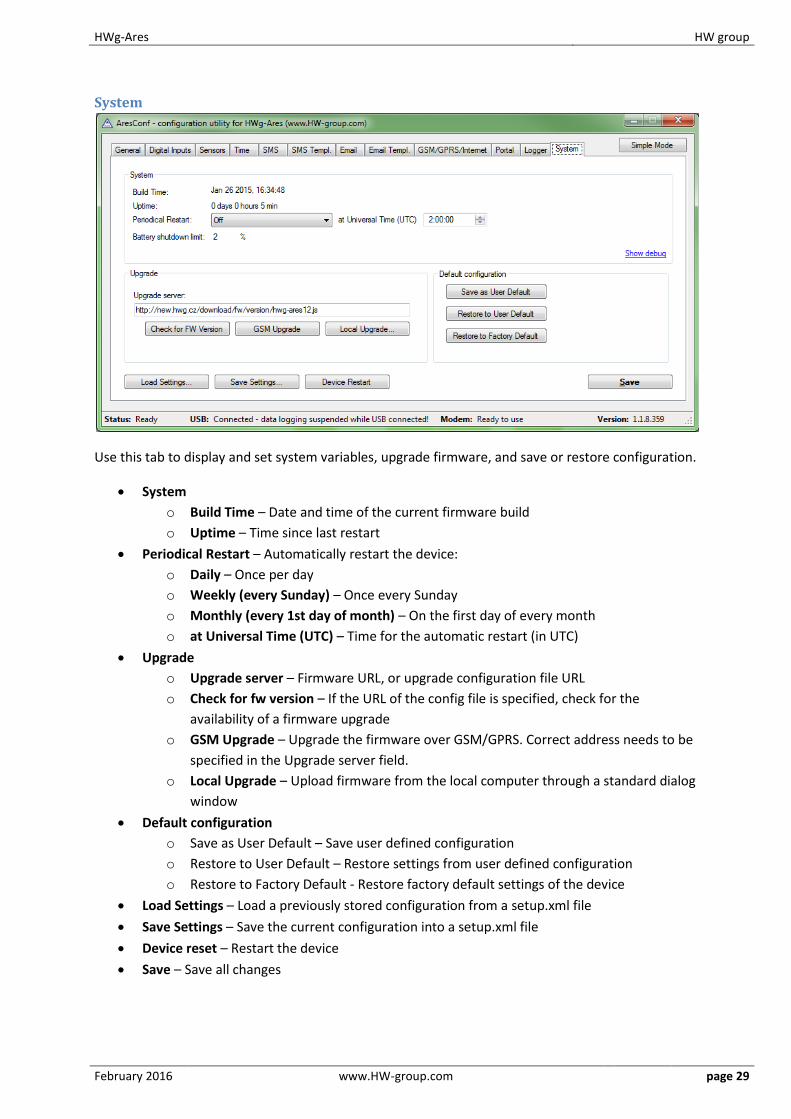
System
Use this tab to display and set system variables, upgrade firmware, and save or restore configuration.
System
o Build Time – Date and time of the current firmware build
o Uptime – Time since last restart
Periodical Restart – Automatically restart the device:
o Daily – Once per day
o Weekly (every Sunday) – Once every Sunday
o Monthly (every 1st day of month) – On the first day of every month
o at Universal Time (UTC) – Time for the automatic restart (in UTC)
Upgrade
o Upgrade server – Firmware URL, or upgrade configuration file URL
o Check for fw version – If the URL of the config file is specified, check for the
availability of a firmware upgrade
o GSM Upgrade – Upgrade the firmware over GSM/GPRS. Correct address needs to be
specified in the Upgrade server field.
o Local Upgrade – Upload firmware from the local computer through a standard dialog
window
Default configuration
o Save as User Default – Save user defined configuration
o Restore to User Default – Restore settings from user defined configuration
o Restore to Factory Default - Restore factory default settings of the device
Load Settings – Load a previously stored configuration from a setup.xml file
Save Settings – Save the current configuration into a setup.xml file
Device reset – Restart the device
Save – Save all changes
HWg-Ares HW group
February 2016 www.HW-group.com page 30
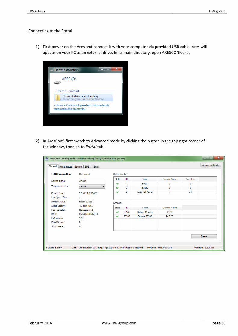
Connecting to the Portal
1) First power on the Ares and connect it with your computer via provided USB cable. Ares will
appear on your PC as an external drive. In its main directory, open ARESCONF.exe.
2) In AresConf, first switch to Advanced mode by clicking the button in the top right corner of
the window, then go to Portal tab.
HWg-Ares HW group
February 2016 www.HW-group.com page 31
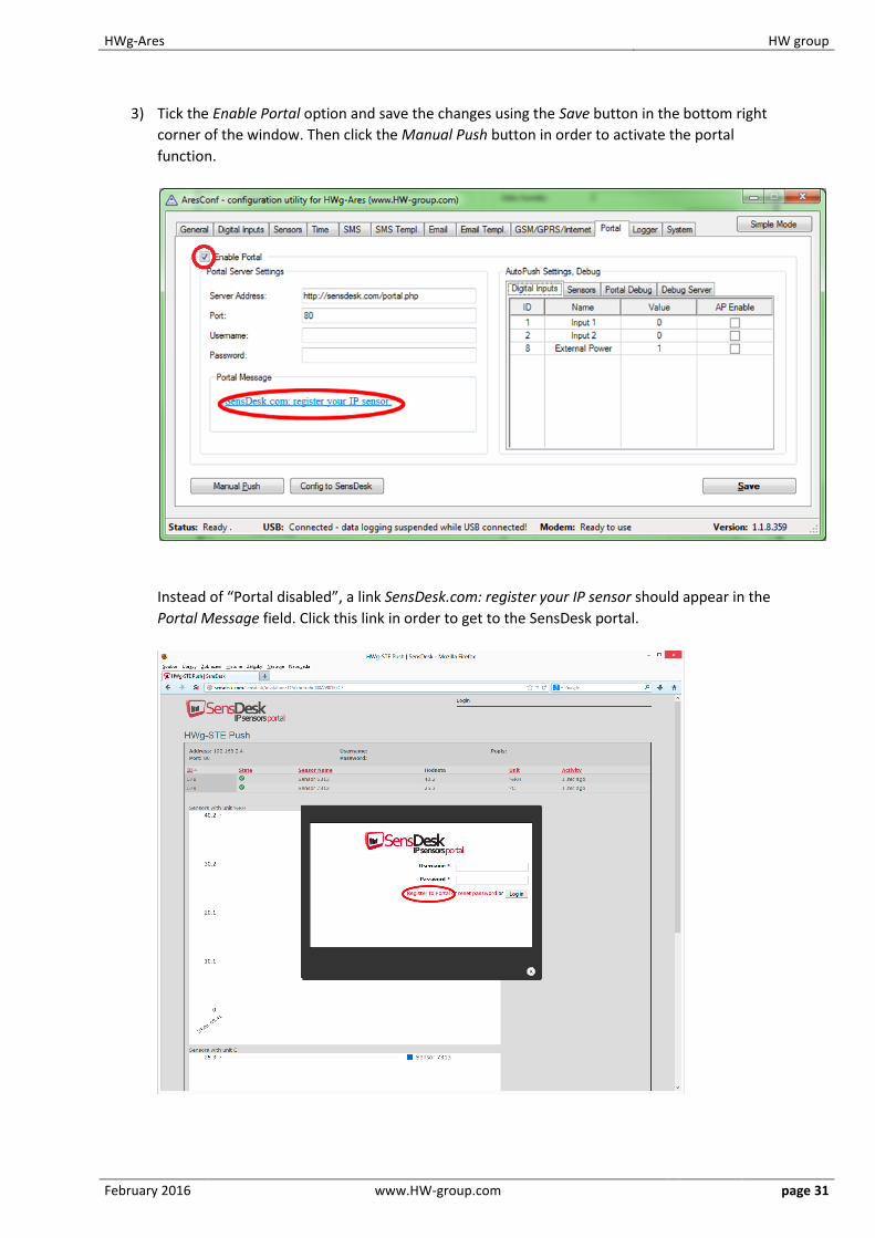
3) Tick the Enable Portal option and save the changes using the Save button in the bottom right
corner of the window. Then click the Manual Push button in order to activate the portal
function.
Instead of “Portal disabled”, a link SensDesk.com: register your IP sensor should appear in the
Portal Message field. Click this link in order to get to the SensDesk portal.
HWg-Ares HW group
February 2016 www.HW-group.com page 32
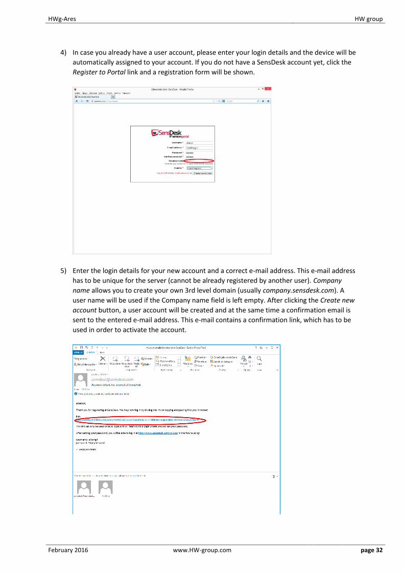
4) In case you already have a user account, please enter your login details and the device will be
automatically assigned to your account. If you do not have a SensDesk account yet, click the
Register to Portal link and a registration form will be shown.
5) Enter the login details for your new account and a correct e-mail address. This e-mail address
has to be unique for the server (cannot be already registered by another user). Company
name allows you to create your own 3rd level domain (usually company.sensdesk.com). A
user name will be used if the Company name field is left empty. After clicking the Create new
account button, a user account will be created and at the same time a confirmation email is
sent to the entered e-mail address. This e-mail contains a confirmation link, which has to be
used in order to activate the account.

HWg-Ares HW group
February 2016 www.HW-group.com page 33
6) By activating the account, you will be redirected to the Invitation page of the device. At this
moment, the data-sending period is set to 10 seconds to show the sensors functionality. This
page is active only for approximately 15 minutes after the activation, then the logging period
changes to 15 minutes.
7) If you check your user account configuration (My Account link), you will find your Push Device
Password. This password, together with your login name, identifies the device in
communication with your account and in communication of mobile applications with
SensDesk. The password cannot be changed and for a security reason it is different to the
login password.
HWg-Ares HW group
February 2016 www.HW-group.com page 34
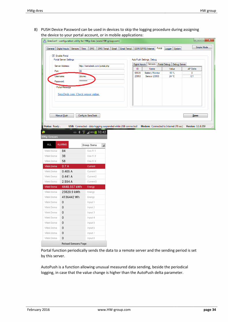
8) PUSH Device Password can be used in devices to skip the logging procedure during assigning
the device to your portal account, or in mobile applications:
Portal function periodically sends the data to a remote server and the sending period is set
by this server.
AutoPush is a function allowing unusual measured data sending, beside the periodical
logging, in case that the value change is higher than the AutoPush delta parameter.

HWg-Ares HW group
February 2016 www.HW-group.com page 35
How to reduce operating costs HWg-Ares units offer functions for reducing overhead GSM/GPRS costs, particularly in the following
scenarios:
Networks that limit the maximum volume of transferred data
Subscribers without a flat-rate data plan
Primary cost-saving options
Disabling GPRS/Internet functions
Disabling data services when roaming outside of the home network
Terminating GPRS connection when idle for longer than 60 seconds
Special functions Alarm information after power up – When any sensor or digital input is in alarm when the power is
connected, all alarm messages according to Ares configuration are sent as soon as the GSM/GPRS
connection is established.
Text message commands
1234 is the default password. You have to use it if your number is not listed as onr of 5 SMS
recipients.
In case you are not using the default password, it has to be only one-word password - cannot contain
any breaks.
STATUS or STATUS SMS – Sends a text message with the current status
STATUS EMAIL – Sends an e-mail with the current status
RESET or REBOOT – Restarts the Ares unit
DEBUG – Returns debugging information
UPGRADE – Without further parameters, upgrades the firmware using the configured
address. Full URL can be included in the message.
1234 STATUS
Test: Value OFF(0)
of input Input 1 is
on state normal.
Your HWgAres12
HWg-Ares HW group
February 2016 www.HW-group.com page 36
Troubleshooting
Modem does not respond
Check the information in the Modem Status field on the General tab:
SIM unplugged – No SIM was found. Insert a SIM, or clean its contact pads.
Modem initializing... – Modem is being initialized. This information should not appear for
more than 10 s. Otherwise, it indicates a modem fault. If this message persists, check the
SIM, clean its contact pads if necessary, and press Reset to restart the unit.
Invalid PIN – PIN code is not entered in the Ares unit, or it is incorrect. Input the correct PIN
in Advanced Config Mode on the GSM/GPRS/Internet tab.
PUK requsted – PUK code is required (must be entered in a different kind of device). The SIM
is blocked until the correct PUK is entered. Take the SIM out and unblock it in a mobile
phone.
Dialing... – Connection to the carrier is being dialed (necessary to establish GPRS
connection). This information should not appear for more than 20 s. Otherwise, it indicates a
modem fault. Check the Dial number in Advanced Config Mode on the GSM/GPRS/Internet
tab. When in doubt, contact your mobile carrier.
Configuring Internet... – Internet connection is being configured (reading IP parameters).
Check the APN in Advanced Config Mode on the GSM/GPRS/Internet tab.
Connected sensor cannot be found
Make sure that the sensors are properly connected.
Restart Ares.
Press Find Sensors on the Sensors tab to detect the missing sensor.
Press Delete All Sensors to remove all sensors, then press Find Sensors to find them again.
I am receiving too many alarm messages
Check the hysteresis setting. By default, hysteresis is set to 1 without regard to the measured
quantity. However, in some cases, this hysteresis is too low.
HWg-Ares HW group
February 2016 www.HW-group.com page 37
Internal memory size HWg-Ares is equipped with 2MB internal memory for storing measured values. The available recording time depends on the number of values being stored. One value takes up 12 bytes of memory. Therefore, 2048kB*1024=2,097,152B/12B = approximately 170,000 records (due to the internal memory organization, the actual number is slightly smaller).
Examples:
3 values Stored once per 300 s 170,000/3 = 56,666 records = 4722 hours = 196 days 1 value Stored once per 30 s 170,000 records = 85,000 minutes = 1416 hours = 54 days 2 values Stored once per 180 s 170,000/2 = 85,000 records = 4250 hours = 177 days
1-Wire UNI sensors 1-Wire sensors are connected using RJ-12 jacks. 1-Wire UNI sensors are a special kind of 1-Wire
sensors. They communicate using the same protocol over the same interface but also contain added
circuitry for connecting special probes. For this reason, 1-Wire UNI sensors may require an
additional power supply (Sens UDI 86).
When the 1-Wire UNI sensors do not explicitly require external power, a maximum of two 1-Wire
UNI sensors can be connected to one Ares port. More sensors can only be connected through the 1-
Wire HUB Power (active hub).
1-Wire UNI sensors strongly influence how long the internal Ares battery lasts. This needs to be taken
into account when planning your system.
For more information about connecting 1-Wire UNI sensors, carefully read the user manual for the
respective sensor.

HWg-Ares HW group
February 2016 www.HW-group.com page 38
Customizing user messages Ares supports up to 4 user-defined custom types of e-mail and text messages. The following macro
commands can be used to insert system variables, sensor names and measured values.
List of macro commands
Name Description
General: General macros
%DEV_NAME% Device name
%MSG_TYPE% Message type (Alarm, status, periodic)
Source sensor:
%SRC_NAME% Sensor name
%SRC_VALUE% Current value
%SRC_UNIT% Unit of the measured value
%SRC_STATUS% Sensors: Invalid, Normal, Alarm, Out Of Range Digital inputs: Normal, Alarm
%SRC_MIN% Lower limit of the Safe Range
%SRC_MAX% Upper limit of the Safe Range
%SRC_ALARM% Alarm begin/end
Sensor with ID=XXXX: Information about other sensors to include in the message
%NAME_XXXX% XXXX sensor name
%VALUE_XXXX% XXXX sensor reading
%UNIT_XXXX% XXXX sensor unit of measurement
%STATUS_XXXX% Sensors: Invalid, Normal, Alarm, Out Of Range Digital inputs: Normal, Alarm
%MIN_XXXX% Lower limit of the Safe Range XXXX
%MAX_XXXX% Upper limit of the Safe Range XXXX
%ALARM_XXXX% Alarm begin/end
HWg-Ares HW group
February 2016 www.HW-group.com page 39
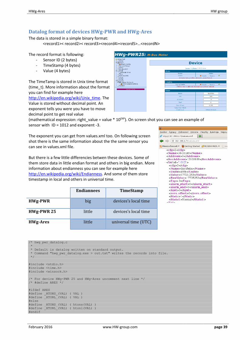
Datalog format of devices HWg-PWR and HWg-Ares The data is stored in a simple binary format:
<record1>< record2>< record3><record4><record5>…<recordN>
The record format is following: - Sensor ID (2 bytes) - TimeStamp (4 bytes) - Value (4 bytes)
The TimeTamp is stored in Unix time format (time_t). More information about the format you can find for example here http://en.wikipedia.org/wiki/Unix_time. The Value is stored without decimal point. An exponent tells you were you have to move decimal point to get real value (mathematical expression: right_value = value * 10EXP). On screen shot you can see an example of sensor with ID = 1012 and exponent -3. The exponent you can get from values.xml too. On following screen shot there is the same information about the the same sensor you can see in values.xml file. But there is a few little differencies betwen these devices. Some of them store data in little endian format and others in big endian. More information about endianness you can see for example here http://en.wikipedia.org/wiki/Endianness. And some of them store timestamp in local and others in universal time.
Endiannees TimeStamp
HWg-PWR big devices’s local time
HWg-PWR 25 little devices’s local time
HWg-Ares little universal time (UTC)
/* hwg_pwr_datalog.c
*
* Default is datalog written on standard output.
* Command "hwg_pwr_datalog.exe > out.txt" writes the records into file.
*/
#include <stdio.h>
#include <time.h>
#include <winsock.h>
/* For device HWg-PWR 25 and HWg-Ares uncomment next line */
/* #define ARES */
#ifdef ARES
#define _HTONS_(VAL) ( VAL )
#define _HTONL_(VAL) ( VAL )
#else
#define _HTONS_(VAL) ( htons(VAL) )
#define _HTONL_(VAL) ( htonl(VAL) )
#endif
HWg-Ares HW group
February 2016 www.HW-group.com page 40
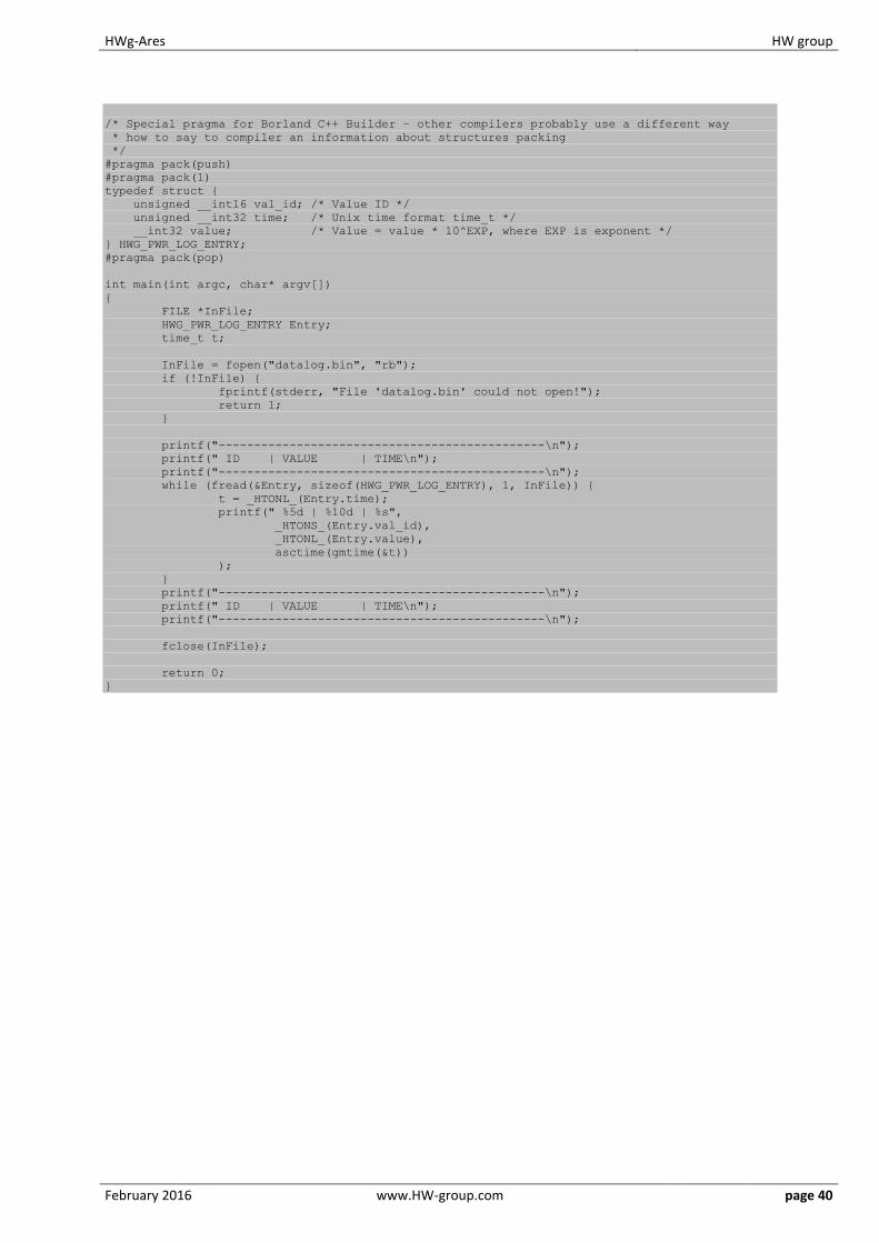
/* Special pragma for Borland C++ Builder – other compilers probably use a different way
* how to say to compiler an information about structures packing
*/
#pragma pack(push)
#pragma pack(1)
typedef struct
unsigned __int16 val_id; /* Value ID */
unsigned __int32 time; /* Unix time format time_t */
__int32 value; /* Value = value * 10^EXP, where EXP is exponent */
HWG_PWR_LOG_ENTRY;
#pragma pack(pop)
int main(int argc, char* argv[])
FILE *InFile;
HWG_PWR_LOG_ENTRY Entry;
time_t t;
InFile = fopen("datalog.bin", "rb");
if (!InFile)
fprintf(stderr, "File 'datalog.bin' could not open!");
return 1;
printf("----------------------------------------------\n");
printf(" ID | VALUE | TIME\n");
printf("----------------------------------------------\n");
while (fread(&Entry, sizeof(HWG_PWR_LOG_ENTRY), 1, InFile))
t = _HTONL_(Entry.time);
printf(" %5d | %10d | %s",
_HTONS_(Entry.val_id),
_HTONL_(Entry.value),
asctime(gmtime(&t))
);
printf("----------------------------------------------\n");
printf(" ID | VALUE | TIME\n");
printf("----------------------------------------------\n");
fclose(InFile);
return 0;
HWg-Ares HW group
February 2016 www.HW-group.com page 41
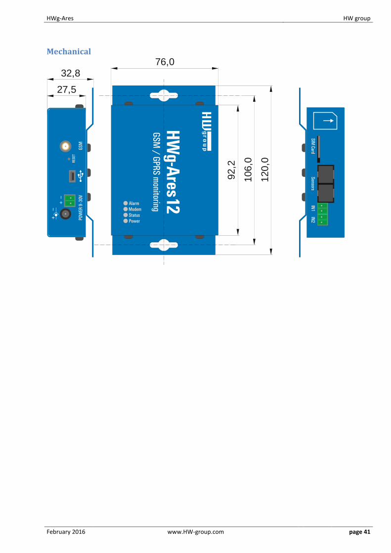
Mechanical
92,2
106,0
120,0
76,0
27,5
32,8