Embed Size (px)
Citation preview
Hybrid aerial and aquatic locomotion in an at-scale robotic insect
Yufeng Chen, E. Farrell Helbling, Nick Gravish, Kevin Ma, and Robert J. Wood
Abstract— Here we present a suite of theoretical, compu-tational, and experimental studies culminating in the firstaerial and aquatic capable insect-scale robot. We develop acomputational fluid dynamics (CFD) simulation to model fluid-wing interaction in air and water. From CFD and a systemdynamics analysis we predict that a multi-modal flappingstrategy will enable locomotion in both air and water for a singledevice. We validate the CFD predictions by running at-scale,robotic wing-flapping experiments. Finally, we demonstrate forthe first time a flying and swimming capable flapping-winginsect-like robot.
I. INTRODUCTION
Mobile robots capable of locomotion through complexenvironments are becoming increasingly essential for search-and-rescue, surveillance, and environment exploration appli-cations [1]. Aerial vehicles [2], [3] are attractive for theseapplications because they can survey large area and bypassheterogeneous ground with ease. However, unlike ground-based robots that have been shown to be able to move acrossrough terrain and within water [4], current aerial robots areincapable of multi-modal locomotion through air and waterwhich limits their utility [5].
The concept of dual aerial, aquatic vehicles emerged in1939 when Russian engineer Boris Ushakov proposed the“flying submarine” [6]. In recent years, several fixed-wingdual aerial, aquatic testing platforms have been developed[7], [8]. However, designs that rely on traditional airfoils togenerate lift and rotary propellers to generate thrust havebeen unsuccessful in achieving aquatic and aerial motion.The difference in density between air and water (1.2kg/m3
and 1000kg/m3, respectively) poses challenges to choosingsuitable wing size, vehicle cruise speed, and propeller speed.While underwater vehicle designs aim to minimize surfacearea to reduce drag, aerial vehicle designs need large airfoilsto maintain lift. This design conflict, in addition to thereduction of rotary motor efficiency at small scales, makesfixed wing designs ineffective for hybrid aerial, aquaticmicro-vehicles.
There are a number of biological examples for hybridaerial and aquatic locomotion including a number of fish,birds, and insect species [9], [10], [11]. In particular, puffinsand guillemots [10] are aquatic birds that both fly and swimby flapping-wings with adaptive kinematics for air and water.
To achieve multi-modal locomotion in a flapping-wingvehicle, wing kinematics must be adapted based on the fluid
These authors are with the School of Engineering and AppliedSciences, Harvard University, Cambridge, MA 02138, USA, and theWyss Institute for Biologically Inspired Engineering, Harvard University,Boston, MA, 02115, USA (email: yufengchen,ehelbling, gravish, kev-inma,[email protected])
Aerial environment
Aquatic environment
Fig. 1. The Harvard RoboBee is an 80mg flapping-wing aerial micro-robot. The flapping-wing design makes the robot a potential dual aerial,aquatic vehicle that varies flapping strategies in different fluid media. Thisconceptual illustration shows a RoboBee inspecting an buoyant object byflying in air, swimming in water, and making transitions between the fluids.
mechanics and system dynamics within these environmentsdue to changes in fluid density and viscosity. For instance,lift-enhancing, unsteady mechanisms such as the develop-ment and shedding of the leading edge vortex (LEV) changewith varying Reynolds number. While many previous studiesexplored these effects using dynamically scaled models [12],these experiments do not allow simultaneous inertia matchingto investigate system dynamics or wing flexibility in waterand air. Hence, to develop design principles for roboticaerial and aquatic locomotion, it is necessary to developa theoretical and experimental basis of flapping-wing fluid-mechanics in these environments. Fig. 1 shows a conceptualillustration of multi-modal locomotion in which robots canland on ground and sample the environment, fly acrosscomplex terrain, and swim within water.
The Harvard RoboBee, shown in Fig. 2a, is an under-actuated flapping-wing micro-aerial vehicle that is potentiallycapable of both aquatic and aerial locomotion. The robotutilizes bimorph piezoelectric actuators to actively control thewing stroke motion, while the wing pitch motion is passivelymediated by a polyimide flexure (Fig. 2c). Previous work onaerodynamic modeling [12], [13] and control algorithms [2]have lead to successful hovering and a number of trajectoryfollowing maneuvers in air.
Here we study flapping flight in air and water using numer-ical models and fluid mechanics experiments culminating inthe first demonstration of a flight and swim capable flapping-wing robot. We first give a high-level scaling analysis toestimate the appropriate operating frequency and flappingamplitude that lead to suitable passive wing kinematics in
2015 IEEE/RSJ International Conference on Intelligent Robots and Systems (IROS)Congress Center HamburgSept 28 - Oct 2, 2015. Hamburg, Germany
978-1-4799-9993-4/15/$31.00 ©2015 IEEE 331
a)
c)
b)
z
x
R
c(x)winghinge
z
x yφ
φ
z
xy
ψ
ψ
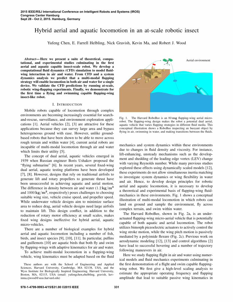
Fig. 2. RoboBee geometrical and kinematic parameters. a) Stroke angleφ and pitch angle ψ relative to the robot. b) φ rotates with respect to thez-axis and ψ rotates with respect to the x-axis. c) The wing planform usedfor experiments and simulations. The wing span is defined by R and wingchord c varies along the wing span direction. The compliant flexure positiondefines the coordinate system origin.
both fluids. To fully quantify the passive wing-fluid interac-tion in air and in water, we introduce a three dimensionalcomputational fluid dynamics model (3D-CFD) to study theeffects of decreasing Reynolds number and changing kine-matics. Aquatic flapping experiments are performed to assessmodel accuracy and we observe excellent agreement. Basedon the computational results, we find a flapping strategy forthe RoboBee and demonstrate open loop swimming.
II. FLUID MODELING AND VEHICLE DYNAMICS
A. Flapping Kinematics
While insect wing kinematics have three degrees of free-dom (DOF) during hover [15], stroke plane deviation isusually negligible compared to in-plane stroke motions andspanwise pitching. Consequently, most flapping-wing robotsemploy two rotational DOF to reduce system complexity.The RoboBee utilizes this design and its flapping kinematicsare shown in Fig. 2a. As illustrated in Fig. 2b, the rotationwith respect to the positive z-axis is defined as the strokemotion φ. The amplitude and frequency of stroke motionare fully controlled by a piezoelectric actuator. The secondDOF, ψ, is defined with respect to the negative x-axis and ispassively controlled by a compliant flexure. Fig. 2c shows theflexure position, the wing planform, and labels local chordlength c(x) and wing span R.
When the actuators are driven with a sinusoidal inputaround 100 − 140Hz in air, the measured pitch motionclosely resembles a phase shifted sinusoid. Fig. 3 illustratesa typical flap cycle. Analytically, the wing stroke and pitchkinematics can be written as
φ(t) = φmax cos(2πft)ψ(t) = −ψmax sin(2πft− δ), (1)
where φmax is the stroke amplitude, ψmax is the pitchamplitude, f is the flapping frequency and δ is the relativephase.
0 0.25 0.5 0.75 1 1.25−50
−25
0
25
50
degr
ee
Time
a)
b)ψϕ
-δ
downstroke
upstroke
upstrokedownstroke
Fig. 3. RoboBee flapping kinematics. a) Upstroke and downstroke of atypical flapping period. Wing stroke φ is actively controlled and pitch ψ ispassive. b) Experimentally measured φ(t) and ψ(t). These functions canbe fit to equation (1). The time scale is normalized to one flapping period.
B. Scaling analysis
We identify the frequency range at which a flapping-wingaerial robot can operate in an aquatic environment using thequasi-steady formula:
FL =1
2CLρU
2rmsS, (2)
where FL is mean lift force, CL is the time averaged liftcoefficient, ρ is the fluid density, Urms is the root meansquare of wing tip velocity, and S is the wing surface area.Since the wing planform, inertia, and hinge stiffness areunchanged as the vehicle transitions from air to water, weneed to change input frequency and stroke amplitude tomaintain the desired mean lift forces. Invoking equation (2)leads to
ρair(φmax,airRfair)2 = ρwater(φmax,waterRfwater)
2,(3)
For an under-actuated flapping-wing aerial robot like theRoboBee, φmax is actively controlled by vehicle actuation.If φmax is chosen to remain constant, then the flappingfrequency in water can be estimated as:
fwater =
√ρairρwater
fair (4)
The quasi-steady model also gives estimate of the fluid powerdissipation in air and water:
P = F · Urms ∼=1
2CLρU
3rmsS (5)
Substituting equation (4) into equation (5) suggests thatfluid power dissipation ratio in air and water is inverselyproportional to the square root of the fluid density ratio:
PairPwater
∼=√ρwaterρair
(6)
332
C. Numerical model with fully prescribed kinematics
The scaling analysis of equation (2) does not considerthe Reynolds number of the fluid-wing interaction. Reynoldsnumber is an important factor for flapping-wing flight and isthe ratio of inertial to viscous forces:
Re =UrmsR
ν, (7)
where ν is the kinematic viscosity of the immersed fluid. Asshown in a previous study [14], changes in passive pitchingcan lead to over 70% change in mean lift generation. Hence,it is important to model these unsteady effects using highfidelity computational solvers.
We implement a CFD model that solves the three dimen-sional incompressible Navier Stokes equation:
∂u∂t + u · ∇u = − 1
ρ∇p+ ν∇2u
∇ · u = 0(8)
where u = (u, v, w) is the fluid velocity field and p isthe pressure field. We further impose a non-slip boundarycondition for the velocity field along the wing surface and afar field pressure boundary condition:
u|wing = (u, v, w)|wingp|∞ = 0
(9)
The Reynolds number, in the non-dimensionalized form ofequation (8), can be interpreted as the ratio between inertialand viscous force contribution, which affects vortex growthand consequently force generation.
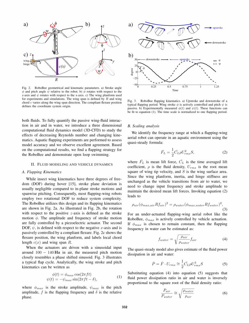
We implement the numerical solver using the nodal dis-continuous Galerkin finite element method on a movingCartesian coordinate system. The wing planform and thechord-wise cross section are modeled as thin ellipses. Fig. 4shows an illustration of the wing surface mesh, the inertialcoordinate system (x, y, z) and the moving coordinate sys-tem (ξ, η, ς). The computational mesh is generated from theopen source package gmsh [16]. The solver uses first-orderLagrange polynomials as the interpolation basis for eachtetrahedral element. The Navier Stokes solver is based ona multi-step method introduced in [17]. A first-order limiterbased on [18] is implemented to remove artificial numericaloscillations. Finally, given solutions to the flow fields, theinstantaneous force and torque with respect to wing root arecomputed by numerically integrating over the shear stresstensor:
F =´wing
n · σda,T =
´wing
r × (n · σ)da(10)
where σ = −pI + µ(∇u+∇uT ) is the shear stress tensor,r is the displacement from wing root and n is the local wingsurface normal at the differential surface da. This numericalsolver takes as input the prescribed flapping kinematicsas time varying boundary conditions to the Navier Stokesequation.
The simulation is compared to a previous flapping exper-iment using measured kinematic parameters φmax = 35◦,ψmax = 43◦, δ = 0◦ and f = 120Hz. The measured
η
ζξ
x
y
z
10c
Time
c)d)
2 3 4 5 6
0
0.5
1
F L [
mN
]
a) b)
Fig. 4. Computational mesh of 3D-CFD simulations and simulationvalidation. a) The spherical computational domain radius is 10 times themean wing chord. b) Definitions of the inertial coordinate system (x, y, z)and the moving coordinate system (ξ, η, ς). Both origins are at the leadingedge of the wing root. c) An enlarged view of wing surface mesh. Thecomputational mesh consists of 140,000 tetrahedral elements and 15,000surface elements. d) A comparison between experimentally measured liftforce (red) and simulated lift force (green) using measured kinematics.
instantaneous lift force is processed using a 500Hz low passfilter and is shown in Fig. 4d (red curve). The computedinstantaneous lift force (green curve) closely matches theexperimental measurement. The relative error of numericalmodel is 16% in this case.
D. Numerical model with passive hinge pitching
Our fully-prescribed CFD is capable of reproducing theexperimentally observed aerodynamic forces on flappingwings (Fig. 4d), however many fluid-structure interactions,including the wings of the RoboBee, involve flexible ele-ments. To study fluid-wing interaction we model the com-pliant flexure as a torsional spring. At each computationaltime step, we find the fluid torque component along the wingpitch axis. The wing pitch component of the Euler angularmomentum equation
∑τ i = I · ω + w × (I · ω) can be
expanded as
Kψ + τfluid = −Ixxψ − (Iyy − Izz)φ2 cosψ sinψ, (11)
where K is the wing hinge stiffness, τfluid is the fluidtorque along wing pitch axis, Ixx, Iyy and Izz are the wingprincipal moments of inertia. This second order ordinarydifferential equation describes the passive wing pitchingmotion. Solutions from the Navier Stokes equation are usedto calculate fluid torque τfluid, which is the input to equation(11). (ψ, ψ, ψ) are solutions to equation (11) and serveas inputs to equation (8). Solving this coupled ODE-PDEsystem allows us to study fluid-wing interaction. We givethe value of K in section IIIB.
E. Vehicle dynamics and energetics
When a flapping-wing robot is placed in an aquatic en-vironment, the vehicle’s dynamics change due to increased
333
damping from the water. We give an analysis of the buoyancyeffect, change of system resonance, cruise speed, uprightstability and system energetics for the Harvard RoboBee inwater.
The current RoboBee is primarily composed of piezoelec-tric ceramics and carbon fiber whose densities are 7g/cm3
and 1.6g/cm3, respectively. In an aquatic environment,buoyancy accounts for less than 14% of the vehicle weight,therefore wing flapping must be the main contribution tothe lift force. The robot is designed such that its aerialflapping frequency centers around the system resonance inair to achieve large wing stroke amplitudes. A previous study[19] from our group found that system resonance is wellestimated using a linearized lumped parameter model. In anaquatic environment, the added mass and effective dampingmore than double. Consequently, the vehicle becomes over-damped and the maximum stroke amplitude reduces toaround 30◦ at low frequencies. Thus we predict that forsuccessful locomotion in water, we will need to drive thewings at higher frequency to account for the reduction inamplitude.
To address the swimming capabilities of RoboBee weconsider fluid drag during locomotion. In an aerial lateralmaneuver, the RoboBee can achieve velocities of 0.5m/s,which is about 10% of the maximum wing stroke velocity.The aerodynamic drag on the airframe is negligible comparedto forces on the wing. In water, the maximum wing strokevelocity is around 20 cm/s and this places an upper boundon the vehicle speed. Fluid drag becomes significant whenvehicle speed exceeds 6.5 cm/s, at which point the drag onthe airframe exceeds 70% of the thrust according to equation(2). Thus, we estimate the vehicle mobility will be limitedto 10 cm/s in water.
Changes in flying kinematics and fluid density also affectvehicle upright stability. Compared to aerial flight, the robotflaps at a reduced frequency but produces equivalent fluidforces and torques. Consequently, the amplitude of the bodyoscillation is magnified by the ratio of flapping frequenciesin air and water– approximately 15 – during open loop takeoff or low speed swimming (< 1 cm/s). On the contrary,fluid torque acting on the robot’s airframe enhances uprightstability at high vehicle speed (> 5 cm/s) because the robotgeometric center is designed to be higher than the center ofmass. This analysis is supported by the observation that theRoboBee remains upright during free fall in water.
The scaling analysis in Section II compares fluid powerdissipation in air and water. The robot efficiency also dependson the loss from the piezo-bending acuators and transmis-sion flexures. The piezoelectric actuators are modelled ascapacitive plates and the power efficiency is proportionalto operating frequency. The robot transmission efficiency issimilar in air and water because frictional loss in compliantflexures is negligible. Compared to hovering flight in air,flapping locomotion in water costs less fluid dissipation buthas lower actuator efficiency. Experimental comparison oftotal power usage in air and water is given in Section IV.
2c
actuator
wing
transmission
input signal
high speed camera
compliant hinge
2c
a)
c)
b)
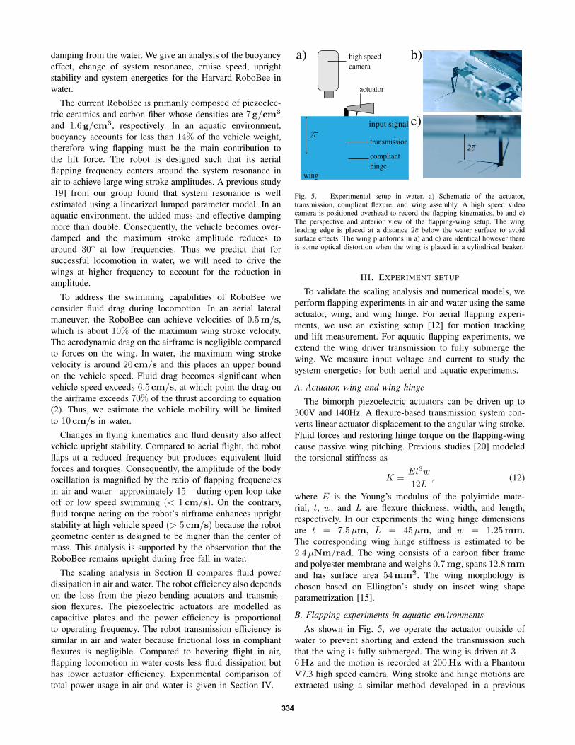
Fig. 5. Experimental setup in water. a) Schematic of the actuator,transmission, compliant flexure, and wing assembly. A high speed videocamera is positioned overhead to record the flapping kinematics. b) and c)The perspective and anterior view of the flapping-wing setup. The wingleading edge is placed at a distance 2c below the water surface to avoidsurface effects. The wing planforms in a) and c) are identical however thereis some optical distortion when the wing is placed in a cylindrical beaker.
III. EXPERIMENT SETUP
To validate the scaling analysis and numerical models, weperform flapping experiments in air and water using the sameactuator, wing, and wing hinge. For aerial flapping experi-ments, we use an existing setup [12] for motion trackingand lift measurement. For aquatic flapping experiments, weextend the wing driver transmission to fully submerge thewing. We measure input voltage and current to study thesystem energetics for both aerial and aquatic experiments.
A. Actuator, wing and wing hinge
The bimorph piezoelectric actuators can be driven up to300V and 140Hz. A flexure-based transmission system con-verts linear actuator displacement to the angular wing stroke.Fluid forces and restoring hinge torque on the flapping-wingcause passive wing pitching. Previous studies [20] modeledthe torsional stiffness as
K =Et3w
12L, (12)
where E is the Young’s modulus of the polyimide mate-rial, t, w, and L are flexure thickness, width, and length,respectively. In our experiments the wing hinge dimensionsare t = 7.5µm, L = 45µm, and w = 1.25mm.The corresponding wing hinge stiffness is estimated to be2.4µNm/rad. The wing consists of a carbon fiber frameand polyester membrane and weighs 0.7mg, spans 12.8mmand has surface area 54mm2. The wing morphology ischosen based on Ellington’s study on insect wing shapeparametrization [15].
B. Flapping experiments in aquatic environments
As shown in Fig. 5, we operate the actuator outside ofwater to prevent shorting and extend the transmission suchthat the wing is fully submerged. The wing is driven at 3−6Hz and the motion is recorded at 200Hz with a PhantomV7.3 high speed camera. Wing stroke and hinge motions areextracted using a similar method developed in a previous
334
work [13]. The measured passive pitching is later comparedwith a numerical simulation that uses measured wing strokemotion as the input. We do not measure time varying forcesfor flapping experiments in water because of the difficulty toincorporate sensitive electronics.
IV. RESULTS
We run a series of simulations and experiments todemonstrate the feasibility of flapping locomotion in aquaticenvironments. 3D-CFD simulations using fully prescribedkinematics estimated from the scaling analysis are doneto compare flow structures and wing dynamics in air andwater. We further conduct flapping experiments in water tostudy passive pitching. The measured pitching kinematicsare compared with 3D-CFD simulations using a partiallyprescribed kinematic model. In addition, we demonstrateRoboBee open-loop swimming.
A. Flapping in water versus in air
A hovering RoboBee flaps at 120Hz in air with 70◦
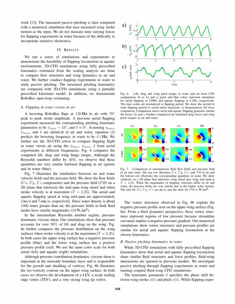
peak to peak stroke amplitude. A previous aerial flappingexperiment measured the corresponding pitching kinematicparameters to be ψmax = 43◦, and δ ≈ 0◦. Assuming φmax,ψmax, and δ are identical in air and water, equation (2)predicts the hovering frequency in water to be 4.1Hz. Wefurther use the 3D-CFD solver to compare flapping flightin water versus air using the φmax, ψmax, δ from aerialexperiments at different frequencies. Fig. 6 compares thecomputed lift, drag and wing hinge torque. Although theReynolds numbers differ by 46%, we observe that thesequantities are very similar between flapping in air (green)and in water (blue).
Fig. 7 illustrates the similarities between air and watervelocity fields and the pressure field. We show the flow fields(Ux, Uy, Uz components) and the pressure field (PR) on a2D plane that intersects the mid-span wing chord and whenstroke velocity is at maximum (T = 2.25). The aerial andaquatic flapping speed at wing mid-span are approximately2m/s and 7 cm/s, respectively. Since water density is about1000 times greater than air, the pressure fields in both fluidmedia have similar magnitudes (10N/m2).
In the intermediate Reynolds number regime, pressuredominates viscous shear. Our simulations show that pressureaccounts for over 90% of lift and drag on the wing. Fig.8a further compares the pressure distribution on the wingsurfaces when stroke velocity is at the maximum (T = 2.25).In both cases the upper wing surface has a negative pressureprofile (blue) and the lower wing surface has a positivepressure profile (red). We use the same color scale for bothaerial (left) and aquatic (right) simulations.
Although pressure contribution dominates, viscous shear isimportant in the unsteady boundary layer and is responsiblefor the growth and shedding of vortices. Fig. 8b illustratesthe iso-vorticity contour on the upper wing surface. In bothcases we observe the development of a LEV, a weak trailingedge vortex (TEV), and a very strong wing tip vortex.
2 3 4 5 60
0.5
1
F L [m
N]
2 3 4 5 60
0.5
1
F D [m
N]
2 3 4 5 6−2
0
2
τ h [m
N m
m]
Time
.
a)
b)
c)
Fig. 6. Lift, drag and wing pitch torque in water and air from CFDcomputation. In a), b) and c) green and blue colors represent simulationfor aerial flapping at 120Hz and aquatic flapping at 4.1Hz, respectively.The time scales are normalized to flapping period. We show the second tosixth flapping period to avoid initial transients. a) Instantaneous lift forcecomparison. Comparison shows aerial and aquatic flapping generates similarlift forces. b) and c) Further comparison pf simulated drag forces and wingpitch torques in air and water.
Ux Uy Uz PR
air
wat
er
Fig. 7. Comparison of instantaneous fluid flow fields and pressure fieldin air and water. The top row illustrates Ux, Uy, Uz, and PR in air andthe bottom row illustrates the corresponding quantities in water. We showsolutions on a 2D plane that intersects wing chord near wing mid-span atT = 2.25. While the magnitudes of flapping velocities differ in air andwater, the pressure fields are very similar due to the higher water density.The unit for Ux, Uy, Uz are m/s, and the units for PR is N/m2.
The vortex structures observed in Fig. 8b explain thenegative pressure profile seen on the upper wing surface (Fig.8a). From a fluid dynamics perspective, these vortex struc-tures represent regions of low pressure because streamlinecurvature implies a negative pressure gradient. Our numericalsimulations show vortex structures and pressure profiles aresimilar for aerial and aquatic flapping locomotion at thechosen kinematics.
B. Passive pitching kinematics in water
While 3D-CFD simulations with fully prescribed flappingkinematics show that aerial and aquatic flapping locomotionshare similar fluid structures and force profiles, fluid-winginteractions are ignored in previous models. We investigatepassive pitching through flapping experiments in water andrunning coupled fluid-wing CFD simulations.
The kinematic parameter δ specifies the phase shift be-tween wing stroke φ(t) and pitch ψ(t). While flapping exper-
335
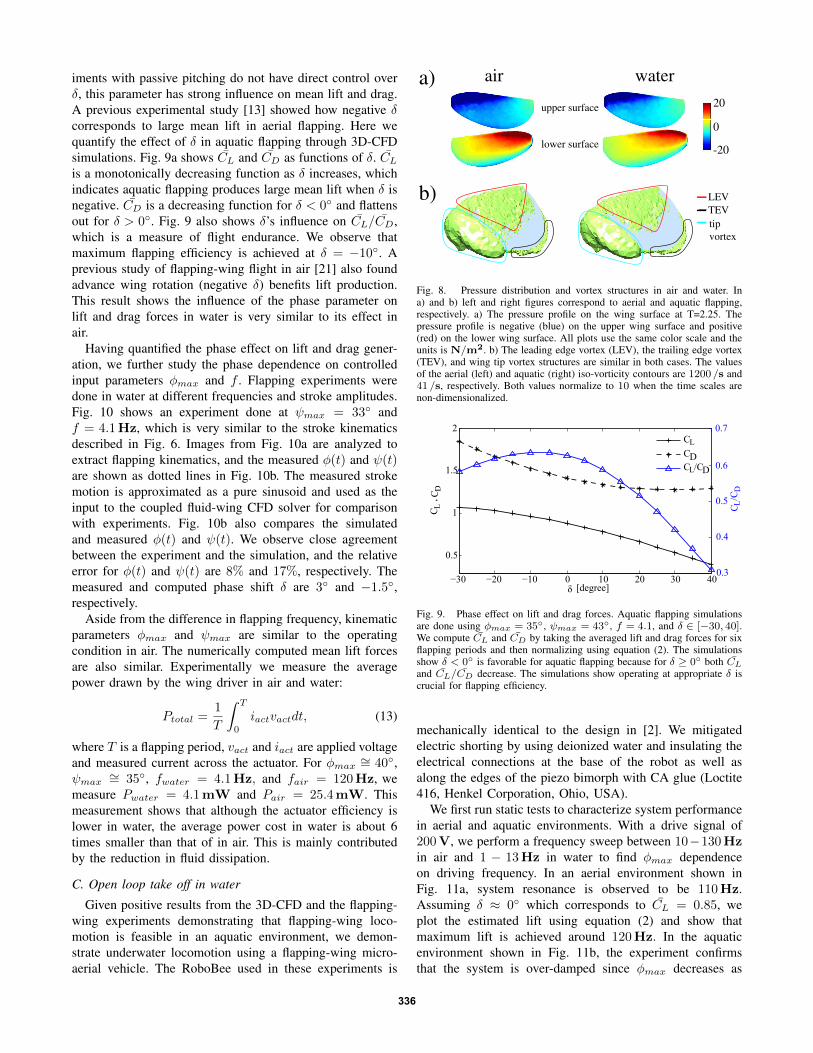
iments with passive pitching do not have direct control overδ, this parameter has strong influence on mean lift and drag.A previous experimental study [13] showed how negative δcorresponds to large mean lift in aerial flapping. Here wequantify the effect of δ in aquatic flapping through 3D-CFDsimulations. Fig. 9a shows CL and CD as functions of δ. CLis a monotonically decreasing function as δ increases, whichindicates aquatic flapping produces large mean lift when δ isnegative. CD is a decreasing function for δ < 0◦ and flattensout for δ > 0◦. Fig. 9 also shows δ’s influence on CL/CD,which is a measure of flight endurance. We observe thatmaximum flapping efficiency is achieved at δ = −10◦. Aprevious study of flapping-wing flight in air [21] also foundadvance wing rotation (negative δ) benefits lift production.This result shows the influence of the phase parameter onlift and drag forces in water is very similar to its effect inair.
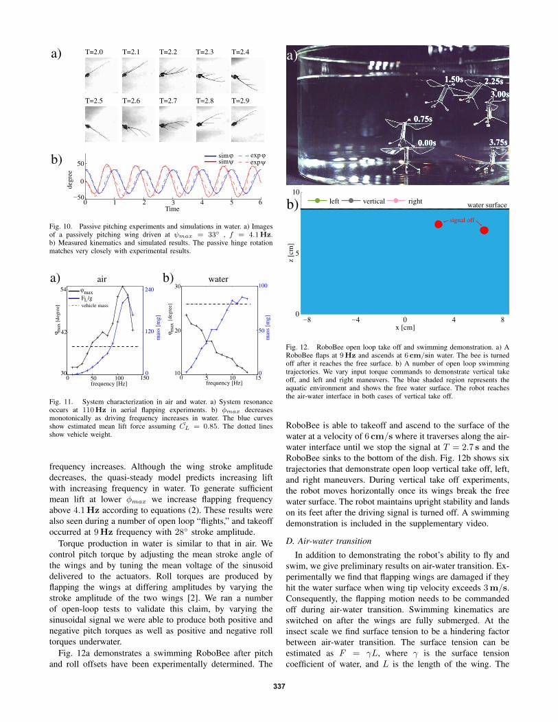
Having quantified the phase effect on lift and drag gener-ation, we further study the phase dependence on controlledinput parameters φmax and f . Flapping experiments weredone in water at different frequencies and stroke amplitudes.Fig. 10 shows an experiment done at ψmax = 33◦ andf = 4.1Hz, which is very similar to the stroke kinematicsdescribed in Fig. 6. Images from Fig. 10a are analyzed toextract flapping kinematics, and the measured φ(t) and ψ(t)are shown as dotted lines in Fig. 10b. The measured strokemotion is approximated as a pure sinusoid and used as theinput to the coupled fluid-wing CFD solver for comparisonwith experiments. Fig. 10b also compares the simulatedand measured φ(t) and ψ(t). We observe close agreementbetween the experiment and the simulation, and the relativeerror for φ(t) and ψ(t) are 8% and 17%, respectively. Themeasured and computed phase shift δ are 3◦ and −1.5◦,respectively.
Aside from the difference in flapping frequency, kinematicparameters φmax and ψmax are similar to the operatingcondition in air. The numerically computed mean lift forcesare also similar. Experimentally we measure the averagepower drawn by the wing driver in air and water:
Ptotal =1
T
ˆ T
0
iactvactdt, (13)
where T is a flapping period, vact and iact are applied voltageand measured current across the actuator. For φmax ∼= 40◦,ψmax ∼= 35◦, fwater = 4.1Hz, and fair = 120Hz, wemeasure Pwater = 4.1mW and Pair = 25.4mW. Thismeasurement shows that although the actuator efficiency islower in water, the average power cost in water is about 6times smaller than that of in air. This is mainly contributedby the reduction in fluid dissipation.
C. Open loop take off in water
Given positive results from the 3D-CFD and the flapping-wing experiments demonstrating that flapping-wing loco-motion is feasible in an aquatic environment, we demon-strate underwater locomotion using a flapping-wing micro-aerial vehicle. The RoboBee used in these experiments is
a)
b)
upper surface
lower surface
20
0
-20
air water
tip vortex
TEVLEV
Fig. 8. Pressure distribution and vortex structures in air and water. Ina) and b) left and right figures correspond to aerial and aquatic flapping,respectively. a) The pressure profile on the wing surface at T=2.25. Thepressure profile is negative (blue) on the upper wing surface and positive(red) on the lower wing surface. All plots use the same color scale and theunits is N/m2. b) The leading edge vortex (LEV), the trailing edge vortex(TEV), and wing tip vortex structures are similar in both cases. The valuesof the aerial (left) and aquatic (right) iso-vorticity contours are 1200 /s and41 /s, respectively. Both values normalize to 10 when the time scales arenon-dimensionalized.
−30 −20 −10 0 10 20 30 40
0.5
1
1.5
2
δ [degree]
C L C
D
0.3
0.4
0.5
0.6
0.7
C L/C
D
CLCDCL/CD
,
Fig. 9. Phase effect on lift and drag forces. Aquatic flapping simulationsare done using φmax = 35◦, ψmax = 43◦, f = 4.1, and δ ∈ [−30, 40].We compute CL and CD by taking the averaged lift and drag forces for sixflapping periods and then normalizing using equation (2). The simulationsshow δ < 0◦ is favorable for aquatic flapping because for δ ≥ 0◦ both CL
and CL/CD decrease. The simulations show operating at appropriate δ iscrucial for flapping efficiency.
mechanically identical to the design in [2]. We mitigatedelectric shorting by using deionized water and insulating theelectrical connections at the base of the robot as well asalong the edges of the piezo bimorph with CA glue (Loctite416, Henkel Corporation, Ohio, USA).
We first run static tests to characterize system performancein aerial and aquatic environments. With a drive signal of200V, we perform a frequency sweep between 10−130Hzin air and 1 − 13Hz in water to find φmax dependenceon driving frequency. In an aerial environment shown inFig. 11a, system resonance is observed to be 110Hz.Assuming δ ≈ 0◦ which corresponds to CL = 0.85, weplot the estimated lift using equation (2) and show thatmaximum lift is achieved around 120Hz. In the aquaticenvironment shown in Fig. 11b, the experiment confirmsthat the system is over-damped since φmax decreases as
336
a) T=2.4
T=2.5
T=2.3
T=2.9T=2.7 T=2.8T=2.6
T=2.2T=2.1T=2.0
b)
b)
c)
0 1 2 3 4 5 60
0.5
1
1.5
Time
mN
F LFD
0 1 2 3 4 5 6−50
0
50
degr
ee
sim expφexpψ
ϕsimψ
Time
Fig. 10. Passive pitching experiments and simulations in water. a) Imagesof a passively pitching wing driven at ψmax = 33◦ , f = 4.1Hz.b) Measured kinematics and simulated results. The passive hinge rotationmatches very closely with experimental results.
b)
0 5 10 1510
20
30
frequency [Hz]
φ max
0
50
100
mas
s [m
g]φ
[deg
ree]
air water
0 50 100 15030
42
54
frequency [Hz]
φ max
0
120
240
mas
s [m
g]
a)ϕmax
vehicle massF /gL
[deg
ree]
Fig. 11. System characterization in air and water. a) System resonanceoccurs at 110Hz in aerial flapping experiments. b) φmax decreasesmonotonically as driving frequency increases in water. The blue curvesshow estimated mean lift force assuming CL = 0.85. The dotted linesshow vehicle weight.
frequency increases. Although the wing stroke amplitudedecreases, the quasi-steady model predicts increasing liftwith increasing frequency in water. To generate sufficientmean lift at lower φmax we increase flapping frequencyabove 4.1Hz according to equations (2). These results werealso seen during a number of open loop “flights,” and takeoffoccurred at 9Hz frequency with 28◦ stroke amplitude.
Torque production in water is similar to that in air. Wecontrol pitch torque by adjusting the mean stroke angle ofthe wings and by tuning the mean voltage of the sinusoiddelivered to the actuators. Roll torques are produced byflapping the wings at differing amplitudes by varying thestroke amplitude of the two wings [2]. We ran a numberof open-loop tests to validate this claim, by varying thesinusoidal signal we were able to produce both positive andnegative pitch torques as well as positive and negative rolltorques underwater.
Fig. 12a demonstrates a swimming RoboBee after pitchand roll offsets have been experimentally determined. The
a)
b)
−8 −4 0 4 80
5
10
x [cm]
z [c
m]
left vertical right water surface
signal off
Fig. 12. RoboBee open loop take off and swimming demonstration. a) ARoboBee flaps at 9Hz and ascends at 6 cm/sin water. The bee is turnedoff after it reaches the free surface. b) A number of open loop swimmingtrajectories. We vary input torque commands to demonstrate vertical takeoff, and left and right maneuvers. The blue shaded region represents theaquatic environment and shows the free water surface. The robot reachesthe air-water interface in both cases of vertical take off.
RoboBee is able to takeoff and ascend to the surface of thewater at a velocity of 6 cm/s where it traverses along the air-water interface until we stop the signal at T = 2.7 s and theRoboBee sinks to the bottom of the dish. Fig. 12b shows sixtrajectories that demonstrate open loop vertical take off, left,and right maneuvers. During vertical take off experiments,the robot moves horizontally once its wings break the freewater surface. The robot maintains upright stability and landson its feet after the driving signal is turned off. A swimmingdemonstration is included in the supplementary video.
D. Air-water transition
In addition to demonstrating the robot’s ability to fly andswim, we give preliminary results on air-water transition. Ex-perimentally we find that flapping wings are damaged if theyhit the water surface when wing tip velocity exceeds 3m/s.Consequently, the flapping motion needs to be commandedoff during air-water transition. Swimming kinematics areswitched on after the wings are fully submerged. At theinsect scale we find surface tension to be a hindering factorbetween air-water transition. The surface tension can beestimated as F = γL, where γ is the surface tensioncoefficient of water, and L is the length of the wing. The
337
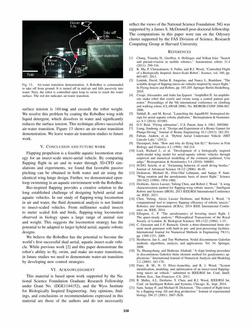
Fig. 13. Air-water transition demonstration. A RoboBee is commandedto take off from ground. It is turned off in mid-air and falls passively intowater. Next, the robot is controlled open loop to swim to reach the watersurface. The red dot indicates air-water transition.
surface tension is 160mg and exceeds the robot weight.We resolve this problem by coating the RoboBee wing withliquid detergent, which dissolves in water and significantlyreduces the surface tension. This technique allows successfulair-water transition. Figure 13 shows an air-water transitiondemonstration. We leave water-air transition studies to futurework.
V. CONCLUSION AND FUTURE WORK
Flapping propulsion is a feasible aquatic locomotion strat-egy for an insect-scale micro-aerial vehicle. By comparingflapping flight in air and in water through 3D-CFD sim-ulations and experiments, we found that favorable passivepitching can be obtained in both water and air using theidentical wing hinge design. Further, we demonstrated open-loop swimming in an aquatic environment with the RoboBee.
Bio-inspired flapping provides a creative solution to thelong established challenge of designing hybrid aerial andaquatic vehicles. In our study of flapping-wing locomotionin air and water, the fluid dynamical analysis is not limitedto insect-scaled vehicles. From millimeter scaled insectsto meter scaled fish and birds, flapping-wing locomotionobserved in biology spans a large range of animal sizeand weight. This suggests the locomotion strategy has thepotential to be adapted to larger hybrid aerial, aquatic roboticdesigns.
We believe the RoboBee has the potential to become theworld’s first successful dual aerial, aquatic insect-scale vehi-cle. While previous work [2] and this paper demonstrate therobot’s ability to fly, swim, and make air-water transitions,in future studies we need to demonstrate water-air transitionby developing new control strategies.
VI. ACKNOWLEDGMENT
This material is based upon work supported by the Na-tional Science Foundation Graduate Research Fellowshipunder Grant No. (DGE1144152), and the Wyss Institutefor Biologically Inspired Engineering. Any opinions, find-ings, and conclusions or recommendations expressed in thismaterial are those of the authors and do not necessarily
reflect the views of the National Science Foundation. NG wassupported by a James S. McDonnell post-doctoral fellowship.The computations in this paper were run on the Odysseycluster supported by the FAS Division of Science, ResearchComputing Group at Harvard University.
REFERENCES
[1] Chung, Timothy H., Geoffrey A. Hollinger, and Volkan Isler. "Searchand pursuit-evasion in mobile robotics." Autonomous robots 31.4(2011): 299-316.
[2] K. Ma, P. Chirarattanon, S. Fuller, and R.J. Wood, “Controlled Flightof a Biologically Inspired, Insect-Scale Robot”, Science, vol. 340, pp.603-607, 2013.
[3] Lentink, David, Stefan R. Jongerius, and Nancy L. Bradshaw. "Thescalable design of flapping micro-air vehicles inspired by insect flight."In Flying Insects and Robots, pp. 185-205. Springer Berlin Heidelberg,2010.
[4] Crespi, Alessandro, and Auke Jan Ijspeert. "AmphiBot II: An amphibi-ous snake robot that crawls and swims using a central pattern gen-erator." Proceedings of the 9th international conference on climbingand walking robots (CLAWAR 2006). No. BIOROB-CONF-2006-001.2006.
[5] Siddall, R., and M. Kovac. "Launching the AquaMAV: bioinspired de-sign for aerial–aquatic robotic platforms." Bioinspiration & biomimet-ics 9.3 (2014): 031001.
[6] D.V. Reid, “Flying submarine”, U.S. Patent, June 4, 1963, 3092060[7] Liang, Jianhong, et al. "Design and Experiment of a Bionic Gannet for
Plunge-Diving." Journal of Bionic Engineering 10.3 (2013): 282-291.[8] Fabian, Andrew, et al. "Hybrid Aerial Underwater Vehicle (MIT
Lincoln Lab)." (2012).[9] Davenport, John. "How and why do flying fish fly?." Reviews in Fish
Biology and Fisheries 4.2 (1994): 184-214.[10] Lock, Richard J., et al. "Development of a biologically inspired
multi-modal wing model for aerial-aquatic robotic vehicles throughempirical and numerical modelling of the common guillemot, Uriaaalge." Bioinspiration & biomimetics 5.4 (2010): 046001.
[11] SUDO, Seiichi, et al. "Swimming behavior of small diving beetles."Journal of Advanced Science 18.1/2 (2006): 46-49.
[12] Dickinson, Michael H., Fritz-Olaf Lehmann, and Sanjay P. Sane."Wing rotation and the aerodynamic basis of insect flight." Science284.5422 (1999): 1954-1960.
[13] Desbiens, Alexis Lussier, Yufeng Chen, and Robert J. Wood. "A wingcharacterization method for flapping-wing robotic insects." IntelligentRobots and Systems (IROS), 2013 IEEE/RSJ International Conferenceon. IEEE, 2013.
[14] Chen, Yufeng, Alexis Lussier Desbiens, and Robert J. Wood. "Acomputational tool to improve flapping efficiency of robotic insects."Robotics and Automation (ICRA), 2014 IEEE International Confer-ence on. IEEE, 2014.
[15] Ellington, C. P. "The aerodynamics of hovering insect flight. I.The quasi-steady analysis." Philosophical Transactions of the RoyalSociety of London. B, Biological Sciences 305.1122 (1984): 1-15.
[16] C. Geuzaine and J.-F. Remacle. Gmsh: a three-dimensional finite ele-ment mesh generator with built-in pre- and post-processing facilities.International Journal for Numerical Methods in Engineering 79(11),pp. 1309-1331, 2009.
[17] Hesthaven, Jan S., and Tim Warburton. Nodal discontinuous Galerkinmethods: algorithms, analysis, and applications. Vol. 54. Springer,2008.
[18] Tu, Shuangzhang, and Shahrouz Aliabadi. "A slope limiting procedurein discontinuous Galerkin finite element method for gasdynamics ap-plications." International Journal of Numerical Analysis and Modeling2.2 (2005): 163-178.
[19] Finio, B. M., N. O. Pérez-Arancibia, and R. J. Wood. "Systemidentification, modeling, and optimization of an insect-sized flapping-wing micro air vehicle." submitted to IEEE/RSJ Int. Conf. Intell.Robots Syst., San Francisco, CA. 2011.
[20] R. Malka, A.L. Desbiens, Y. Chen, and R.J. Wood, IEEE/RSJ Int.Conf. on Intelligent Robots and Systems, Chicago, IL, Sept. 2014.
[21] Sane, Sanjay P., and Michael H. Dickinson. "The control of flight forceby a flapping-wing: lift and drag production." Journal of experimentalbiology 204.15 (2001): 2607-2626.
338


![Locomotion [2015]](https://img.pdfslide.net/doc/110x75/55d39c9ebb61ebfd268b46a2/locomotion-2015.jpg)