Embed Size (px)
Citation preview
Hybrid BARC approaches for FEOL and BEOL integration
Willie Pereza, Stephen Turnera, Nick Brakensieka, Lynne Millsb, Larry Wilsonb,Paul Popab
aBrewer Science, Inc., 2401 Brewer Dr., Rolla, MO 65401bThe Dow Chemical Company, 1712 Building, Midland, MI 48674
ABSTRACT
Spin-on bottom anti-reflective coatings were introduced to the semiconductor industry about 20 years ago to help controlsubstrate reflectivity, improve critical dimension (CD) control, and, most importantly, improve depth of focus window,thus improving throughput and yields. Bottom anti-reflective coating (BARC) materials are either inorganic or organicin nature. Inorganic BARCs are chemical vapor deposition (CVD) films that work on the principle of destructiveinterference to eliminate reflectivity and demand tight thickness control in the BARC layer. In contrast, organic BARCsare generally spin-on polymeric materials that reduce substrate reflectivity by absorbing exposure radiation to providegreater latitude in thickness control. As an added benefit, organic spin-on BARCs also provide a level of planarizationefficiency prior to photoresist deposition to improve depth of focus and process window in the photolithography step.
As feature sizes continue to shrink, etching becomes very challenging due to thin ArF photoresist (PR) layers, which aremuch less etch resistant compared to KrF photoresists. The reduced thickness, as well as the reduced etch resistance, ofthe PR makes it nearly impossible to use the PR as both an imaging and a pattern transfer layer. This has led to thedevelopment of a new class of spin-on “hybrid” BARC materials which not only have improved etch selectivity to thePR due to inorganic functionality but also have the absorbing properties, and hence offer greater process latitude. HybridBARC (H-BARC) materials enable the BARC layer to act as both an anti-reflective coating and as a pattern transferlayer in standard etch-back integration schemes. Due to the polymeric functionality associated with H-BARCs, thesematerials have exceptional gap-fill and planarization properties and can also be used in via-first dual damasceneapplications where similar etch characteristics between interlayer dielectric materials and the via-fill BARC enable betterCD control.
This paper will focus on the benefits of ENSEMBLE* ARC® materials, a new class of spin-on hybrid BARC materials,which can be used in either standard BARC applications or in via-first dual damascene applications which require thatthe BARC act both as an anti-reflective coating and as a via-fill material to assist in CD control during trench etchprocesses. This paper demonstrates lithography with 193-nm resists, resist compatibility, via-fill performance, opticalproperties, and etch rates with different plasma recipes.
1 INTRODUCTION
Bottom anti-reflective coatings (BARCs) were developed about 20 years ago to help control reflections from thesubstrate, improve critical dimension (CD) and most importantly, improve the depth of focus. During that time, chipmanufacturers had two choices of BARCs, either spin-on organic coatings or BARCs deposited by chemical vapordeposition (CVD). Each material has respective advantages and disadvantages. Spin-on BARCs have excellentplanarizing properties and optical properties but etch only slightly faster than the photoresist. CVD BARCs areconformal in nature, have limited optical property ranges, and exhibit excellent etch selectivity to photoresist.
This paper will discuss a new spin-on hybrid BARC (H-BARC) that combines the properties of both CVD and organicBARCs. These include excellent planarizing properties for via-fill or gap-fill approaches and etch selectivity to thephotoresist that rivals that of CVD BARCS. The advantages of H-BARC will be shown by looking at the material
* Trademark of The Dow Chemical Company® Trademark of Brewer Science, Inc.
Copyright 2005 Society of Photo-Optical Instrumentation Engineers. This paper will be published in Proceedings of SPIE, vol. 5753, and is made available as anelectronic preprint with permission of SPIE. One print or electronic copy may be made for personal use only. Systematic or multiple reproduction, distribution tomultiple locations via electronic or other means, duplication of any material in this paper for a fee or for commercial purposes, or modification of the content of thepaper are prohibited.
properties such as shelf life, optical tuning capability, dry-etch selectivity, and wafer cleaning. Photolithography processwindows and resolution capabilities that are comparable to current organic BARCs will be demonstrated. Theplanarizing properties of the material will be demonstrated along with the via-first dual damascene integration throughthe trench etch. Wafer-coating processes were also explored and coat process windows were found to be compatiblewith 300-mm wafer processes.
2 RESULTS AND DISCUSSION
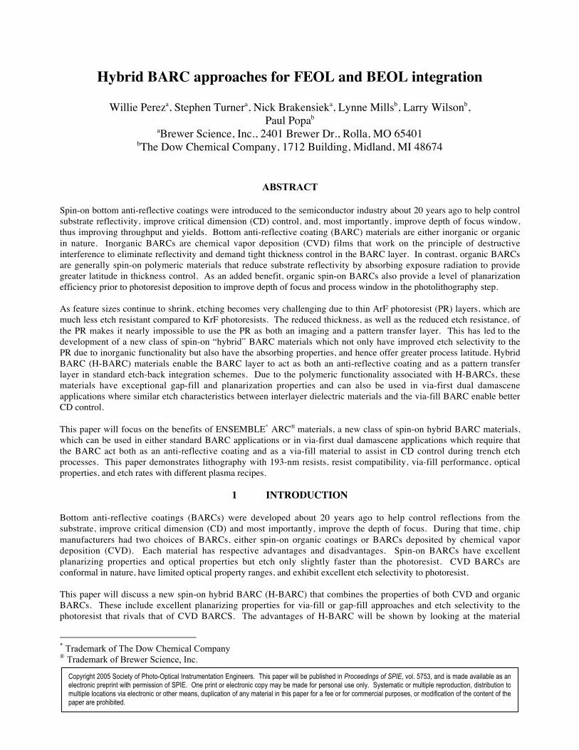
2.1 ENSEMBLE ARC Chemistry/General Properties SectionsENSEMBLE ARC formulations consist of an organosilicate copolymer in a PGMEA (1-methoxy-2-acetoxypropane)solvent system. The organic functionality was chosen to enable tuning of the optical properties of cured films to meetapplication-specific requirements.
ENSEMBLE ARC formulations can be spin coated on standard (photolithography) spin tracks and hot plate curedbetween 175-425°C with no degradation in optical characteristics. Formulations can be selected over a k-value rangefrom 0.15-0.75, with thicknesses ranging from <10 nm to 1000 nm.
Figure 1. ENSEMBLE ARC polymer chemistry.
2.2 Extinction Coefficient and BARC ReflectivityThe extinction coefficient of a BARC material generally depends on the loading of chromophore that is in the material.While reflectance that approaches 0 is ideal, a good target for front-end-of-line (FEOL) and back-end-of-line (BEOL)applications at 193 nm is having reflectance less than 1%. The extinction coefficient for ENSEMBLE ARC films can betuned from k193 ~0.15 – k193 ~0.75. Reflectivity curves (Figure 2) using PROLITH/2 were generated for both first- andsecond-minimum films on silicon where k193 was 0.53 and 0.36, respectively.
Figure 2.
OH
SiO O
R
Si
OHO R
R1 R2
Substrate Reflectivity (Silicon)
0
1
2
3
4
5
6
7
0 10 20 30 40 50 60 70 80 90 100 110 120 130 140 150 160 170 180 190 200
Thickness (nm)
% Re
flecta
nce
ENSEMBLE ARC-3ENSEMBLE ARC-8
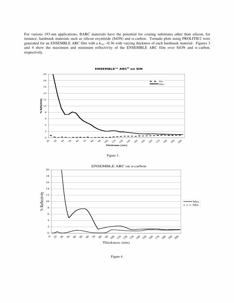
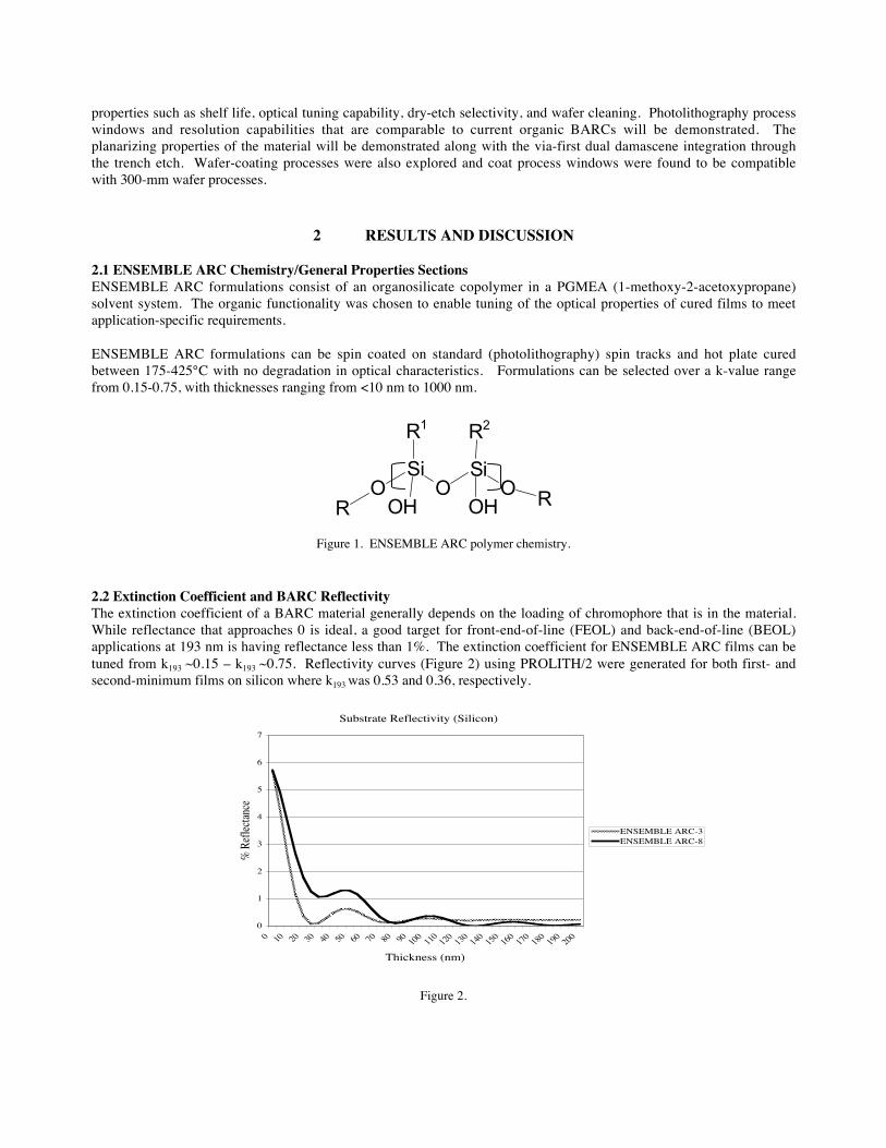
For various 193-nm applications, BARC materials have the potential for coating substrates other than silicon, forinstance, hardmask materials such as silicon oxynitride (SiON) and α-carbon. Tornado plots using PROLITH/2 weregenerated for an ENSEMBLE ARC film with a k193 ~0.36 with varying thickness of each hardmask material. Figures 3and 4 show the maximum and minimum reflectivity of the ENSEMBLE ARC film over SiON and α -carbon,respectively.
Figure 3.
Figure 4.
ENSEMBLE ARC on a-carbon
0
2
4
6
8
10
12
14
16
18
20
0 10 20 30 40 50 60 70 80 90 100 110 120 130 140 150 160 170 180 190 200
Thickness (nm)
% Re
flecti
vity
MaxMin
ENSEMBLE™ ARC® on SiN
0
2
4
6
8
10
12
14
16
18
20
20 30 40 50 60 70 80 90 100
110
120
130
140
150
160
170
180
190
200
Thickness (nm)
% R
efle
ctiv
ity
MinMax
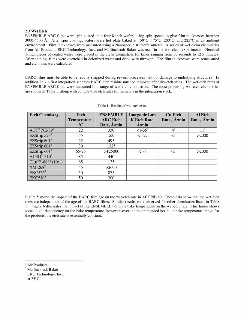
2.3 Wet EtchENSEMBLE ARC films were spin coated onto four 8-inch wafers using spin speeds to give film thicknesses between3000-4500 Å. After spin coating, wafers were hot plate baked at 150°C, 175°C, 200°C, and 225°C in an ambientenvironment. Film thicknesses were measured using a Nanospec 210 interferometer. A series of wet clean chemistriesfrom Air Products, EKC Technology, Inc., and Mallinckrodt Baker was used in the wet clean experiments. Nominal1-inch pieces of coated wafer were placed in the clean chemistries for times ranging from 30 seconds to 12.5 minutes.After etching, films were quenched in deionized water and dried with nitrogen. The film thicknesses were remeasuredand etch rates were calculated.
BARC films must be able to be readily stripped during rework processes without damage to underlying structures. Inaddition, in via-first integration schemes BARC etch residue must be removed after dry-etch steps. The wet-etch rates ofENSEMBLE ARC films were measured in a range of wet-etch chemistries. The most promising wet-etch chemistriesare shown in Table 1, along with comparative etch rates for materials in the integration stack.
Table 1. Results of wet-etch tests.
Etch Chemistry EtchTemperature,
°C
ENSEMBLEARC Etch
Rate, Å/min
Inorganic LowK Etch Rate,
Å/min
Cu EtchRate, Å/min
Al EtchRate, Å/min
ACT® NE-891 22 330 <1-354 44 114
EZStrip 5231 55 1535 <1-27 <1 >2000EZStrip 6011 22 495EZStrip 6011 30 1325EZStrip 6011 65-75 >125000 <1-8 <1 >2000ALEG®-3102 85 440CLκ™-8882 (10:1) 65 135XM-2682 45 >2600EKC5253 50 875EKC5103 50 200
Figure 5 shows the impact of the BARC film age on the wet-etch rate in ACT NE-89. These data show that the wet-etchrates are independent of the age of the BARC films. Similar results were observed for other chemistries listed in Table1. Figure 6 illustrates the impact of the ENSEMBLE hot plate bake temperature on the wet-etch rate. This figure showssome slight dependency on the bake temperature, however, over the recommended hot plate bake temperature range forthe products, the etch rate is essentially constant.
1 Air Products2 Mallinckrodt Baker3 EKC Technology, Inc.4 at 25°C
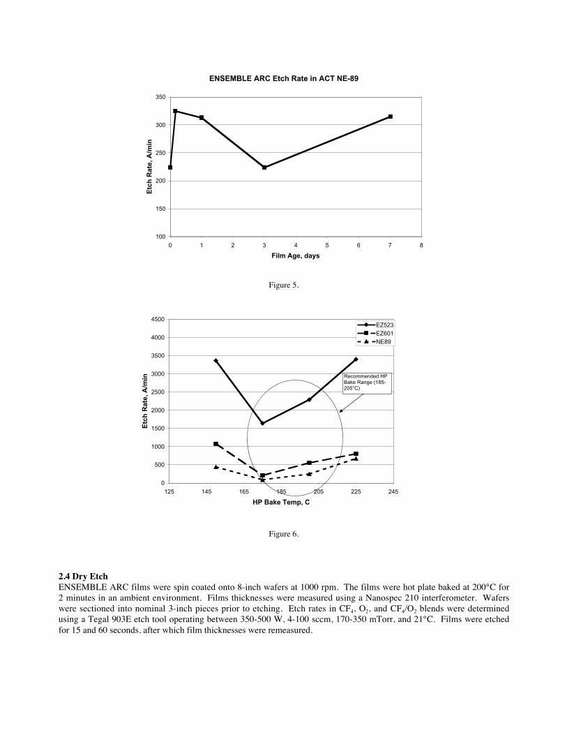
Figure 5.
Figure 6.
2.4 Dry EtchENSEMBLE ARC films were spin coated onto 8-inch wafers at 1000 rpm. The films were hot plate baked at 200°C for2 minutes in an ambient environment. Films thicknesses were measured using a Nanospec 210 interferometer. Waferswere sectioned into nominal 3-inch pieces prior to etching. Etch rates in CF4, O2, and CF4/O2 blends were determinedusing a Tegal 903E etch tool operating between 350-500 W, 4-100 sccm, 170-350 mTorr, and 21°C. Films were etchedfor 15 and 60 seconds, after which film thicknesses were remeasured.
ENSEMBLE ARC Etch Rate in ACT NE-89
100
150
200
250
300
350
0 1 2 3 4 5 6 7 8
Film Age, days
Etc
h R
ate,
A/m
in
0
500
1000
1500
2000
2500
3000
3500
4000
4500
125 145 165 185 205 225 245
HP Bake Temp, C
Etc
h R
ate,
A/m
in
EZ523EZ601NE89
Recommended HP Bake Range (185-205°C)
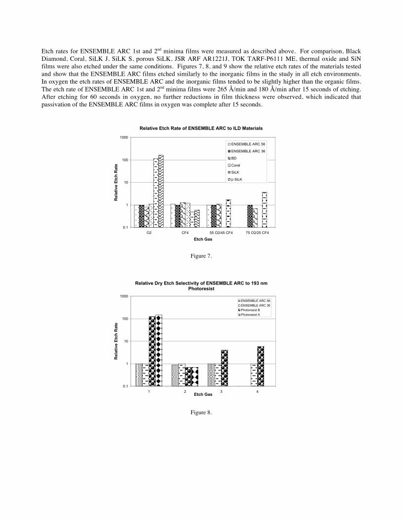
Etch rates for ENSEMBLE ARC 1st and 2nd minima films were measured as described above. For comparison, BlackDiamond, Coral, SiLK J, SiLK S, porous SiLK, JSR ARF AR1221J, TOK TARF-P6111 ME, thermal oxide and SiNfilms were also etched under the same conditions. Figures 7, 8, and 9 show the relative etch rates of the materials testedand show that the ENSEMBLE ARC films etched similarly to the inorganic films in the study in all etch environments.In oxygen the etch rates of ENSEMBLE ARC and the inorganic films tended to be slightly higher than the organic films.The etch rate of ENSEMBLE ARC 1st and 2nd minima films were 265 Å/min and 180 Å/min after 15 seconds of etching.After etching for 60 seconds in oxygen, no further reductions in film thickness were observed, which indicated thatpassivation of the ENSEMBLE ARC films in oxygen was complete after 15 seconds.
Figure 7.
Figure 8.
Relative Etch Rate of ENSEMBLE ARC to ILD Materials
0.1
1
10
100
1000
O2 CF4 55 O2/45 CF4 75 O2/25 CF4
Etch Gas
Rel
ativ
e E
tch
Rat
e
ENSEMBLE ARC 56
ENSEMBLE ARC 36
BD
Coral
SiLK
p SiLK
Relative Dry Etch Selectivity of ENSEMBLE ARC to 193 nm Photoresist
0.1
1
10
100
1000
1 2 3 4Etch Gas
Rel
ativ
e E
tch
Rat
e
ENSEMBLE ARC 56
ENSEMBLE ARC 36
Photoresist B
Photoresist A
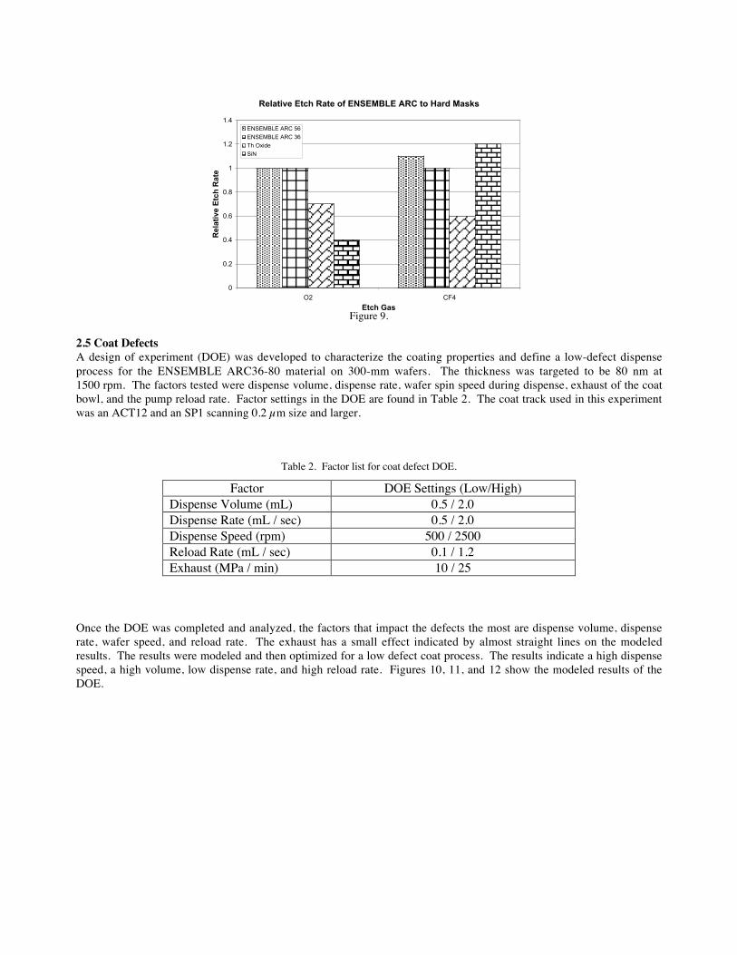
Figure 9.
2.5 Coat DefectsA design of experiment (DOE) was developed to characterize the coating properties and define a low-defect dispenseprocess for the ENSEMBLE ARC36-80 material on 300-mm wafers. The thickness was targeted to be 80 nm at1500 rpm. The factors tested were dispense volume, dispense rate, wafer spin speed during dispense, exhaust of the coatbowl, and the pump reload rate. Factor settings in the DOE are found in Table 2. The coat track used in this experimentwas an ACT12 and an SP1 scanning 0.2 µm size and larger.
Table 2. Factor list for coat defect DOE.
Factor DOE Settings (Low/High)Dispense Volume (mL) 0.5 / 2.0Dispense Rate (mL / sec) 0.5 / 2.0Dispense Speed (rpm) 500 / 2500Reload Rate (mL / sec) 0.1 / 1.2Exhaust (MPa / min) 10 / 25
Once the DOE was completed and analyzed, the factors that impact the defects the most are dispense volume, dispenserate, wafer speed, and reload rate. The exhaust has a small effect indicated by almost straight lines on the modeledresults. The results were modeled and then optimized for a low defect coat process. The results indicate a high dispensespeed, a high volume, low dispense rate, and high reload rate. Figures 10, 11, and 12 show the modeled results of theDOE.
X
Relative Etch Rate of ENSEMBLE ARC to Hard Masks
0
0.2
0.4
0.6
0.8
1
1.2
1.4
O2 CF4
Etch Gas
Rel
ativ
e E
tch
Rat
e
ENSEMBLE ARC 56
ENSEMBLE ARC 36
Th Oxide
SiN
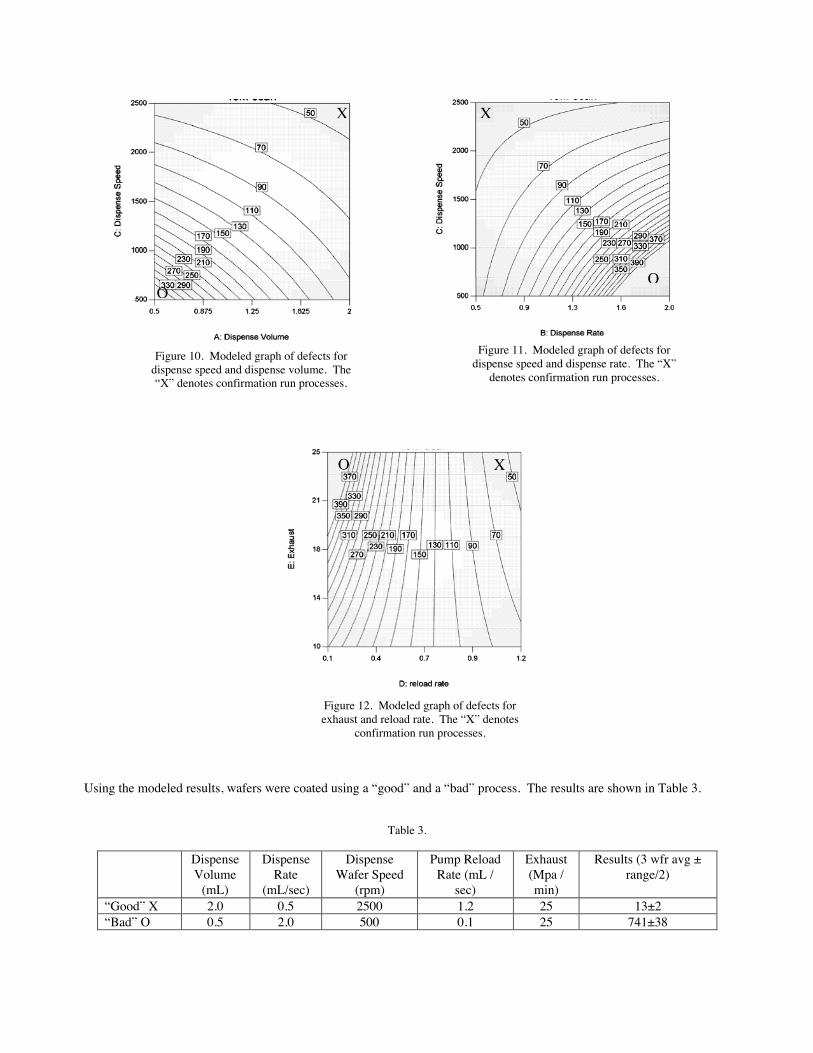
Using the modeled results, wafers were coated using a “good” and a “bad” process. The results are shown in Table 3.
Table 3.
DispenseVolume
(mL)
DispenseRate
(mL/sec)
DispenseWafer Speed
(rpm)
Pump ReloadRate (mL /
sec)
Exhaust(Mpa /min)
Results (3 wfr avg ±range/2)
“Good” X 2.0 0.5 2500 1.2 25 13±2“Bad” O 0.5 2.0 500 0.1 25 741±38
Figure 10. Modeled graph of defects fordispense speed and dispense volume. The“X” denotes confirmation run processes.
Figure 11. Modeled graph of defects fordispense speed and dispense rate. The “X”
denotes confirmation run processes.
X X
OO
Figure 12. Modeled graph of defects forexhaust and reload rate. The “X” denotes
confirmation run processes.
XO
With almost two orders of magnitude difference in defect count depending on the process, optimization is necessary forspecific production environments, but the capability for production-worthy spin-coat processes has been demonstrated.
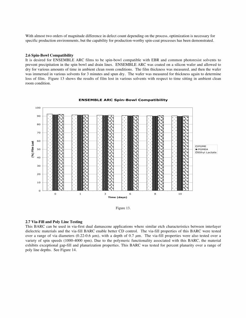
2.6 Spin-Bowl CompatibilityIt is desired for ENSEMBLE ARC films to be spin-bowl compatible with EBR and common photoresist solvents toprevent precipitation in the spin bowl and drain lines. ENSEMBLE ARC was coated on a silicon wafer and allowed todry for various amounts of time in ambient clean room conditions. The film thickness was measured, and then the waferwas immersed in various solvents for 3 minutes and spun dry. The wafer was measured for thickness again to determineloss of film. Figure 13 shows the results of film lost in various solvents with respect to time sitting in ambient cleanroom condition.
ENSEMBLE ARC Spin-Bowl Compatibility
0
10
20
30
40
50
60
70
80
90
100
0 1 3 6 8 10
Time (days)
(%)
Film
Los
t
PGMEPGMEAEthyl Lactate
Figure 13.
2.7 Via-Fill and Poly Line TestingThis BARC can be used in via-first dual damascene applications where similar etch characteristics between interlayerdielectric materials and the via-fill BARC enable better CD control. The via-fill properties of this BARC were testedover a range of via diameters (0.22-0.6 µm), with a depth of 0.7 µm. The via-fill properties were also tested over avariety of spin speeds (1000-4000 rpm). Due to the polymeric functionality associated with this BARC, the materialexhibits exceptional gap-fill and planarization properties. This BARC was tested for percent planarity over a range ofpoly line depths. See Figure 14.
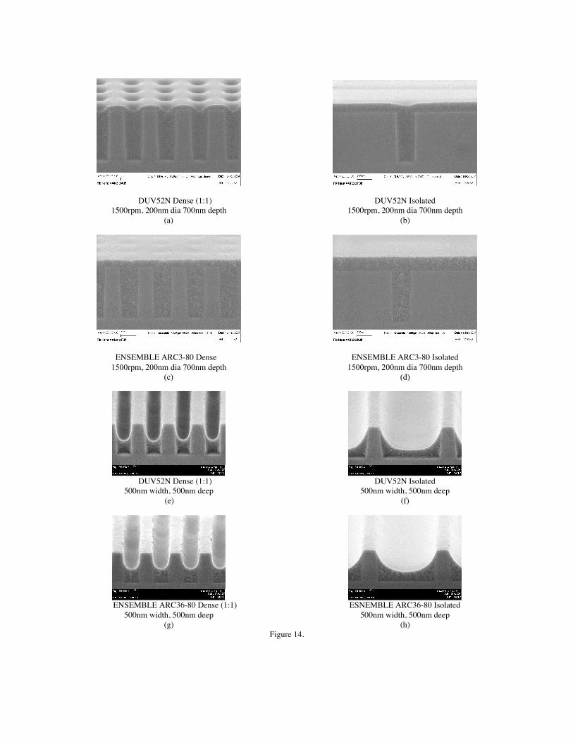
DUV52N Dense (1:1) DUV52N Isolated1500rpm, 200nm dia 700nm depth 1500rpm, 200nm dia 700nm depth
(a) (b)
ENSEMBLE ARC3-80 Dense ENSEMBLE ARC3-80 Isolated1500rpm, 200nm dia 700nm depth 1500rpm, 200nm dia 700nm depth
(c) (d)
DUV52N Dense (1:1) DUV52N Isolated500nm width, 500nm deep 500nm width, 500nm deep
(e) (f)
ENSEMBLE ARC36-80 Dense (1:1) ESNEMBLE ARC36-80 Isolated500nm width, 500nm deep 500nm width, 500nm deep
(g) (h)Figure 14.
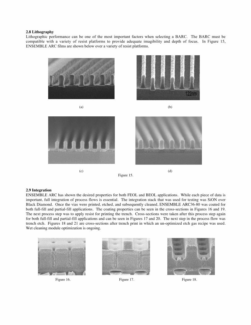
2.8 LithographyLithographic performance can be one of the most important factors when selecting a BARC. The BARC must becompatible with a variety of resist platforms to provide adequate imagibility and depth of focus. In Figure 15,ENSEMBLE ARC films are shown below over a variety of resist platforms.
(a) (b)
(c) (d)Figure 15.
2.9 IntegrationENSEMBLE ARC has shown the desired properties for both FEOL and BEOL applications. While each piece of data isimportant, full integration of process flows is essential. The integration stack that was used for testing was SiON overBlack Diamond. Once the vias were printed, etched, and subsequently cleaned, ENSEMBLE ARC36-80 was coated forboth full-fill and partial-fill applications. The coating properties can be seen in the cross-sections in Figures 16 and 19.The next process step was to apply resist for printing the trench. Cross-sections were taken after this process step againfor both full-fill and partial-fill applications and can be seen in Figures 17 and 20. The next step in the process flow wastrench etch. Figures 18 and 21 are cross-sections after trench print in which an un-optimized etch gas recipe was used.Wet cleaning module optimization is ongoing.
Figure 16. Figure 17. Figure 18.
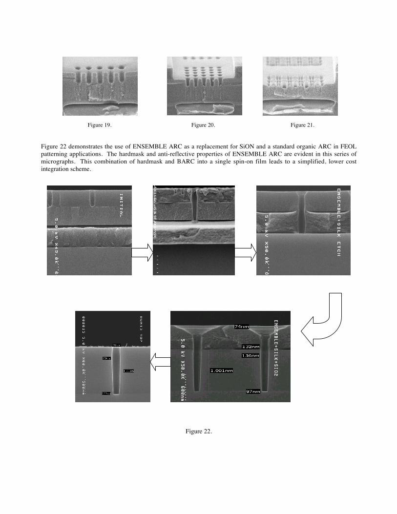
Figure 19. Figure 20. Figure 21.
Figure 22 demonstrates the use of ENSEMBLE ARC as a replacement for SiON and a standard organic ARC in FEOLpatterning applications. The hardmask and anti-reflective properties of ENSEMBLE ARC are evident in this series ofmicrographs. This combination of hardmask and BARC into a single spin-on film leads to a simplified, lower costintegration scheme.
Figure 22.
3 SUMMARY
ENSEMBLE ARC films represent a new class of spin-on hybrid BARC materials that are well suited for both FEOL andBEOL applications. These films can be used in both blanket film applications to control substrate reflectivity and inapplications where via-fill and planarization are required. In addition, the hybrid nature of these films provides forimproved etch selectivity between the BARC and photoresist, allowing for dual functionality during integration.ENSEMBLE ARC formulations also have excellent shelf lives, are compatible with leading 193-nm photoresists, exhibitstable film properties as a function of film age, and are tunable to allow for reflectivity control across key substrates.
4 ACKNOWLEDGMENTS
The authors would like to thank the following for their hard work and many contributions:
• Brewer Science, Inc.• The Dow Chemical Company• SiLKNet AllianceSM Partners
o Air Products - ACTo ATMIo Dupont EKC Technologyo SEZ Groupo Tokyo Electron Limited
• Mallinckrodt Baker