Embed Size (px)
Citation preview

General rights Copyright and moral rights for the publications made accessible in the public portal are retained by the authors and/or other copyright owners and it is a condition of accessing publications that users recognise and abide by the legal requirements associated with these rights.
Users may download and print one copy of any publication from the public portal for the purpose of private study or research.
You may not further distribute the material or use it for any profit-making activity or commercial gain
You may freely distribute the URL identifying the publication in the public portal If you believe that this document breaches copyright please contact us providing details, and we will remove access to the work immediately and investigate your claim.
Downloaded from orbit.dtu.dk on: Feb 17, 2022
Hybrid damper with stroke amplification for damping of offshore wind turbines
Brodersen, Mark L.; Høgsberg, Jan
Published in:Wind Energy
Link to article, DOI:10.1002/we.1977
Publication date:2016
Document VersionPeer reviewed version
Link back to DTU Orbit
Citation (APA):Brodersen, M. L., & Høgsberg, J. (2016). Hybrid damper with stroke amplification for damping of offshore windturbines. Wind Energy, 19(12), 2223–2238. https://doi.org/10.1002/we.1977

HYBRID DAMPER WITH STROKE AMPLIFICATION FOR DAMPING OF
OFFSHORE WIND TURBINES
MARK L. BRODERSEN(1) AND JAN HØGSBERG(1)
(1)DEPARTMENT OF MECHANICAL ENGINEERING, TECHNICAL UNIVERSITY OF DENMARK,
DK-2800 KGS. LYNGBY, DENMARK
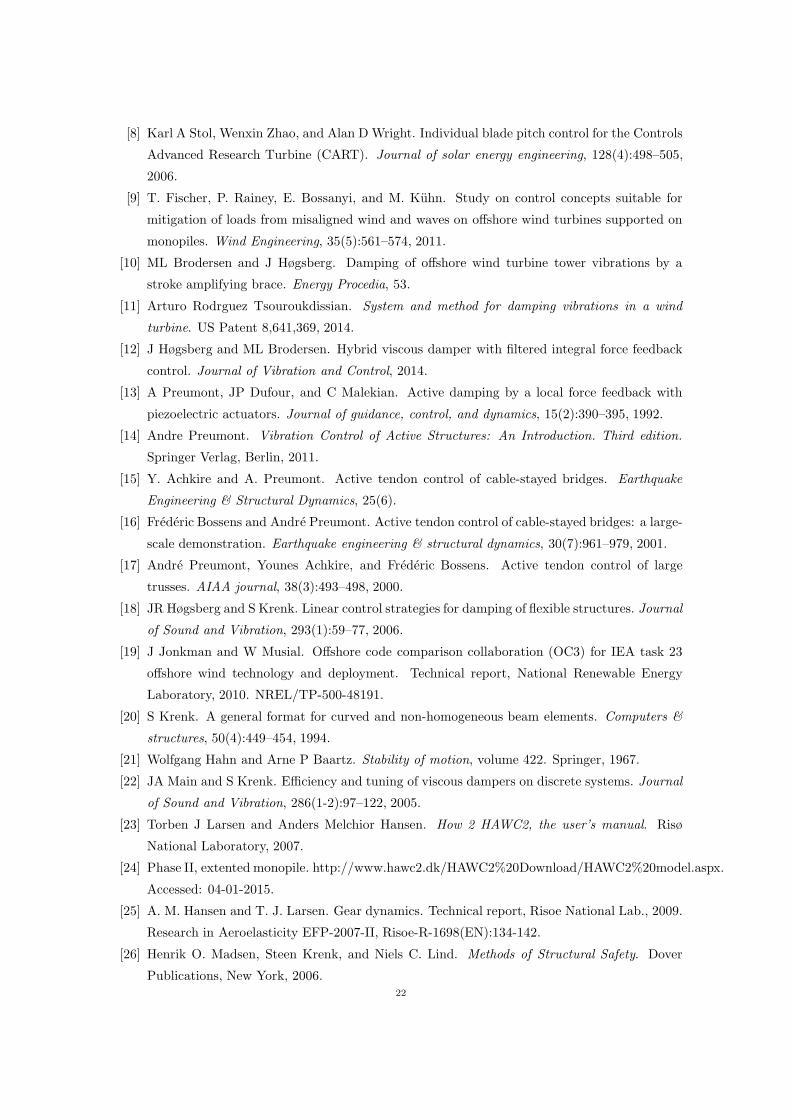
Abstract. The magnitude of tower vibrations of offshore wind turbines is a key design driver
for the feasibility of the monopile support structure. A novel control concept for the damping
of these tower vibrations is proposed, where viscous type hybrid dampers are installed at the
bottom of the wind turbine tower. The proposed hybrid damper consists of a passive viscous
dash-pot placed in series with a load cell and an active actuator. By integrated force feedback
control of the actuator motion the associated displacement amplitude over the viscous damper
can be increased compared to the passive viscous case, hereby significantly increasing the feasi-
bility of viscous dampers acting at the bottom of the wind tower. To avoid drift in the actuator
displacement a filtered time integration of the measured force signal is introduced. Numerical
examples demonstrate that the filtered time integration control leads to performance similar
to that of passive viscous damping and substantial amplification of the damper deformation
without actuator drift.
1. Introduction
The monopile foundation is currently the most used support structure for shallow water offshore
wind turbines. Compared to a jacket type foundation, the monopile has a simple and relatively
cost-effective design, which on the other hand also makes it prone to wave loading. It is primarily
a combination of the two lowest tower modes, the side-side mode and the fore-aft mode as seen in
figure 1, which are excited by the waves. Especially waves misaligned with the wind direction can
cause large fatigue damage due to the absence of aerodynamic damping in the direction lateral
to the wind [1, 2]. In the near future the majority of new offshore wind turbines will be taller
and/or positioned at deeper waters, whereby the natural frequencies of the side-side mode and
the fore-aft mode will be lowered. The natural frequencies will then move closer to the primary
excitation frequency of the waves, causing resonant excitation to be more frequent. This may
render the monopile support structure unfeasible. A means for increasing the feasibility of the
monopile support structure, would be to add external damping to the critical modes of the wind
turbine structure.
Several concepts have been proposed for structural control of tower vibrations of offshore wind
turbines. Passive resonant damper concepts like e.g. a pendulum absorber or a tuned mass or
liquid damper are well established concepts in structural control, and therefore widely used by the
wind turbine manufactures for vibration control of offshore wind turbines [3, 4, 5, 6, 7]. A resonant
damper like a pendulum absorber has the potential to achieve very high damping ratios, though
in order for the absorber to be effective, large mass and space at the top of the wind turbine
is required. As wind turbines become larger and located at larger water depths these mass and1

Figure 1. Fore-aft mode and side-side mode of a fixed offshore wind turbine
space requirements will increase and thereby limit the feasibility of pendulum type absorbers even
further. Active concepts such as individual pitch control or active generator torque control has
also been proposed for control of the side-side vibrations, see [8, 9]. These concepts are relatively
easy to integrate in a standard rotor-nacelle-assembly unit, though they may increase loading on
other components such as the gear-box or the pitch actuators. More recently a passive concept has
been proposed in [10], where dampers are installed inside the tower to act on the local curvature
of the corresponding tower bending deformation. This concept utilizes stroke amplifying braces in
order to amplify the relative motion of the tower, though the amplification is inherently limited
for passive damping devices. The specific concept of using toggle-brace damping systems for wind
turbines has recently been covered by the patent [11].
In the present paper it is proposed to install dampers inside the bottom of the tower by means
of the viscous hybrid damper concept introduced in [12]. The hybrid damper concept includes
a pure viscous dash-pot placed in series with both a force sensor and an active actuator. The
actuator motion is controlled using a decentralized collocated control algorithm based on a filtered
Integral Force Feedback (IFF) from the force sensor. In this paper a slightly modified controller
scheme, without the filter time constant, is used. Eliminating the filter time scale from the
feedback equation, the pure IFF scheme, introduced in [13, 14] for control of truss structures
using piezoelectric transducers, is recovered. Among other applications the IFF format has also
successfully been applied for control of cable stayed bridges [15, 16] and for control of large space
structures [17]. In the present hybrid damper concept appropriate tuning of this IFF controller
scheme introduces amplified motion of the structure locally at the damper position, leading to
significantly larger stroke over the viscous dash-pot. Thus, the stroke amplification obtained
by toggle-brace systems in [10, 11] is in the present case realized by active control. Since the
generated hybrid damper force is in phase with the associated damper velocity the controller
scheme is theoretically unconditionally stable in an idealized environment without time delays
and actuator saturation.2

G(ω)
q
uc
f
(c)(a) (b)
s-s
f-a
Figure 2. (a) Hybrid damper concept and its installation in the lower section ofa wind turbine tower: (b) side view and (c) top view.
2. The Hybrid Damper Concept
The hybrid damper concept is illustrated in figure 2(a). It consists of a viscous dash-pot with
viscous damping parameter c in series with a load cell, measuring the damper force f , and an
active actuator with piston motion q. The motion over the hybrid damper is given by u whereby
the measured force produced by the viscous dash-pot is given as
f(t) = c(u(t)− q(t)). (1)
The displacement of the actuator piston q(t) is determined by an Integral Force Feedback (IFF)
scheme [13], given as
q(t) = −gf(t), (2)
where g is the control gain. For g = 0 the passive limit without piston motion q = 0 is recovered. In
large scale structures, such as wind turbines, the desired damper reference signal q may be realized
by a hydraulic actuator with for example PID control of the piston motion, measured by a LVDT
or an alternative displacement transducer. The implementation of active control strategies, and
in particular IFF, is described in detail in [14]. The installation of the hybrid damper in a wind
turbine tower is illustrated in figure 2(b,c). The direction of the fore-aft vibrations in the direction
of the rotor is denoted by f-a, while the direction of the side-side vibrations is denoted by s-s. In
these, the two most critical tower modes with regards to wave excitation, the tower is primarily
deformed in bending, and the damper should therefore be installed at the bottom of the tower in
order to maximize modal interaction, as also illustrated in a side-view of the tower in figure 2(b).
During operation the Rotor Nacelle Assembly (RNA) will change orientation following the direction
of the wind. Thus, three or more dampers are needed in the circumferential direction to form a
symmetric layout that leads to efficient damping of both the fore-aft mode and the side-side mode,
independent of the specific orientation of the RNA. The three-damper layout, as illustrated by the
top-view of the tower in figure 2(c), is also applied for the toggle-brace systems in [10, 11].3

2.1. Frequency domain analysis. The hybrid damper characteristics are now investigated in
the frequency domain. Harmonic solutions are assumed using the complex representations
u(t) = u exp iωt , q(t) = q exp iωt , f(t) = f exp iωt , (3)
with angular frequency ω and with amplitudes denoted by a bar. In the frequency domain the
damper force in (1) is given by
f = iωc (u− q). (4)
The corresponding feedback equation in (2) now appears as
iωq = −gf, (5)
which can be rewritten in terms of the transfer function
G(ω) =−g
iω, (6)
to establish the feedback relation q = G(ω)f shown in figure 2(a). The relation between damper
force f and the displacement u of the hybrid damper is obtained by eliminating q between (4) and
(5). This gives the force relation
f = iωcHu. (7)
where the transfer function H in the present case is given as the constant
H =1
1− ν. (8)
with non-dimensional gain
ν = c g. (9)
In (8) the transfer function H modifies the transfer relation of the hybrid damper relative to
the pure viscous damper, which in the following will be used as benchmark for assessing the
performance of the proposed hybrid damper concept. In order to have positive damping it is
required that H > 0, thereby invoking the limit ν < 1. The phase ϕ of the damper force is defined
by the relation tanϕ = Im [H ] /Re [H ], which for ν < 1 gives ϕ = 0. Thus, for the pure IFF
controller the damper force is fully in phase with damper velocity, and the controller is therefore
unconditionally stable for ν < 1. The amplification of the displacement over the viscous dash-pot
relative to the passive case with q = 0 is given by the magnitude |H | of the transfer function
|H | =∣
∣
∣
∣
u− q
u
∣
∣
∣
∣
=
∣
∣
∣
∣
1
1− ν
∣
∣
∣
∣
. (10)
Thus, for 0 < ν < 1 the displacement of the viscous dash-pot is amplified relative to the passive
case with q = 0, whereas for ν = 0 the pure viscous case is recovered. In this way the hybrid
damper can be used to increase the feasibility of installing a viscous damper in a flexible structure,
such as a wind turbine, where the displacement over the damper is inherently small.4

2.2. Filtered integration. The hybrid damper implemented with the IFF controller, as given
by the feedback relation in (6), has a pole at s = iω = 0 in the Laplace domain. This makes it
prone to drift in the actuator displacement, which again can lead to saturation of the actuator
signal. In order to reduce this drift the actuator velocity is now integrated by a suitable filter.
First, the actuator velocity is defined as an independent variable v = q and the feedback equation
in (2) is therefore rewritten as
v(t) = −gf(t). (11)
Subsequently, the actuator displacement q is obtained by integration of the velocity v through the
second order filter
ωfq(t) + q(t) + τf q(t) = v(t). (12)
The first term with the corner frequency ωf reduces drift and potential actuator saturation in
the command displacement signal q. Note, that this is similar to the introduction of a forgetting
factor in [13]. The last term in (12) with the filter time constant τf is added to compensate for
the phase delay caused by the first term. The influence of this term will be demonstrated later in
this section. Combining equation (11) and (12) gives
ωfq(t) + q(t) + τf q(t) = −gf(t). (13)
In the frequency domain, obtained by assuming harmonic solutions as in (3), this equation can be
written as(
ωf − ω2τf + iω)
q = −gf , (14)
whereby the modified transfer function G(ω) is given as
G(ω) =−g
ωf − ω2τf + iω. (15)
The previous pole at iω = 0 for the pure IFF format is now replaced by the pair of complex
conjugate poles
s = iω = −1/(2τf)±√
ωf/τf
√
1/(4ωfτf ) − 1, (16)
which reduces the actuator drift. Combining (14) with (4), the transfer function H(ω) defined in
(7) is now given as
H(ω) =ωf − τfω
2 + iω
ωf − τfω2 + iω (1− ν), (17)
with real and imaginary parts
Re [H(ω)] =
(
ωf − τfω2)2
+ ω2 (1− ν)
(ωf − τfω2)2+ ω2 (1− ν)
2 , Im [H(ω)] =ων
(
ωf − τfω2)
(ωf − τfω2)2+ ω2 (1− ν)
2 . (18)
For ωf , τf → 0 the transfer function recovers the expression given in (8) for the pure IFF format.
The frequency characteristics of H(ω) given in (17) are conveniently described in terms of the
magnitude
|H(ω)| =∣
∣
∣
∣
u− q
u
∣
∣
∣
∣
=
√
√
√
√
(
ωf − τfω2)2
+ ω2
(ωf − τfω2)2+ ω2 (1− ν)
2 , (19)
5

which represents the amplification of the damper displacement, and by the phase angle ϕ obtained
from
tanϕ =Im [H(ω)]
Re [H(ω)]=
ων(
ωf − τfω2)
ω2(1 − ν) + (ωf − τfω2)2 . (20)
It can be seen from (19) that the amplification of the displacement over the viscous dash-pot is
in general reduced for non-negative filter parameters ωf , τf > 0, which unfortunately reduces the
performance of the hybrid damper. However, by choosing ωf and τf so that ωf = τfω20 , where ω0
is the natural frequency of the structure, the magnitude and phase at this structural frequency ω0
becomes
|H(ω0)| =∣
∣
∣
∣
1
1− ν
∣
∣
∣
∣
, ϕ(ω0) = 0. (21)
It is seen that the result for the pure IFF format in (8) is in fact recovered at structural resonance
corresponding to ω = ω0.
Figure 3 shows a plot of (a) the magnitude |H(ω)| as given in (19) and (b) the phase angle ϕ
obtained from (20). The non-dimensional gain value is ν = 0.5, while different values of ωf and τf
are chosen. The solid curves in the figure are for different non-negative values of ωf = τfω20 < ω0,
while the dashed curves represent the particular case with τf = 0 and different non-negative values
of ωf < ω0. The values of ωf are ω0/20 (blue), ω0/8 (red), ω0/5 (green), and 0.00 (straight black).
The latter case with ωf = 0 corresponds to the case without filtered integration. For τf = 0 and
0 < ωf < ω0 (dashed curves) the magnitude is seen to be reduced to |H(ω)| < 2 compared to the
case without filtered integration (straight black solid curve) with |H | = 2. The reduction is largest
for frequencies below the resonance frequency ω0. For the case with ωf = τfω20 (solid curves) the
magnitude is reduced for the frequency intervals below and above the resonance frequency ω0,
while around the resonance frequency ω = ω0 the desired level of stroke amplification is retained.
Thus, the amplification of the displacement of the damper is at its maximum at the structural
resonance frequency where effective vibration damping is required.
The phase angle is plotted in figure 3(b). For τf = 0 (dashed curves) a phase lead ϕ > 0
is observed compared to the pure viscous case (straight black solid curve). For the case with
ωf = τfω20 (solid curves) a phase lead is observed below the resonance frequency ω0, while a phase
lag ϕ < 0 is obtained for frequencies above ω0 with vanishing phase angle ϕ = 0 at ω = ω0. A
phase lead ϕ > 0 implies that the damper force acts ahead of the conjugated damper velocity,
while a phase lag ϕ < 0 corresponds to a damper force trailing velocity. The effect of a phase
difference compared to pure viscous damping is discussed in [18], where it is demonstrated that
a phase lead results in improved damper performance. Thus, by choosing the filter parameters
from the equality ωf = τfω20 the drift of the actuator motion can be reduced, while retaining the
desired displacement amplification at the natural frequency ω0 of the critical mode(s) of the wind
turbine. In practice, the filter parameters should be chosen large enough to limit drift, but also
small enough not to deteriorate the damping performance of the hybrid damper in the frequency
range close to the structural frequency ω0.6

10−2
100
102
1
1.25
1.5
1.75
2
(a)0.0
0.05
0.20
ω/ω0
|H|
10−2
100
102
−0.1
0
0.1
(b)
ω/ω0
ϕ/π
Figure 3. (a) Magnitude and (b) phase of frequency transfer function H(ω)for ν = 0.5 with τf = ωf/ω
20 (solid) and τf = 0 (dashed), and filter frequency
ωf = 0.0 (black), ω0/20 (blue), ω0/8 (red) and ω0/5 (green).
3. Properties of wind turbine and dampers
The present section introduces a numerical wind turbine model for later use in the investigation of
damping of tower vibrations, with particular emphasis on the installation of the hybrid dampers.
The wind turbine model is the 5 MW offshore wind turbine from the Offshore Code Comparison
Collaboration study (OC3), see [19]. The wind turbine is supported by a monopile foundation,
which is positioned at 20 m water depth with a penetration length of 36 m and connected to the
wind turbine tower 10 m above Mean Sea Level (MSL). The tower is connected to the nacelle at
87.6 m above MSL, with the hub located at a height of 90 m. Dampers are installed on the tower
wall at the bottom of the tower with the upper point of attachment located 4m above the bottom.
3.1. Linear beam model. Initially, the wind turbine is assumed to be at standstill, and the
wind turbine and monopile are therefore represented by a linear discrete beam model, with the
horizontal y-axis in the rotor direction, the horizontal x-axis lateral to the rotor direction and
the vertical z-axis in the longitudinal tower direction. The beam model is three-dimensional with
three translational displacements uTi = [uxiuyiuzi] and three rotations ϕT = [ϕxiϕyiϕzi] at element
nodes i = 1 and 2. Thus, the displacements of beam element j are described by the 12 degrees of
freedom (dofs) contained in vector uTj =
[
uT1 ϕ
T1 u
T2 ϕ
T2
]
, as shown in figure 4a. The equations of
motion for the total number of structural dofs in u are given by
Mu+Cu+Ku = f − fd, (22)
where M, C and K are the mass, damping and stiffness matrix, respectively, while f is the external
load vector and fd is the force vector representing the contributions from all hybrid dampers
installed inside the tower. The stiffness matrix K consists of a contribution from the constitutive
stiffness matrix of the tower and monopile, based on the complementary energy principle following
[20], and a contribution from the soil stiffness, which is represented using linear springs. The
mass matrix M represents the distributed mass and inertia of the tower and monopile, and the
inertia and mass of the nacelle, rotor and blades which are lumped at the top of the tower. The7

damping matrix C is a proportional damping matrix that represents structural - and soil damping,
and it is tuned to provide the two targeted tower modes (fore-aft and side-side) with a realistic
damping ratio of ζst = 0.0115 at standstill. The connection of the hybrid dampers to the tower
are conveniently described by a connectivity vector w for each damper, whereby the damper force
vector is given by the summation
fd =
r∑
k=1
wkfk, (23)
where r is the total number of dampers. Since the hybrid dampers are collocated the damper
displacement uk of the k′th damper is determined as
uk = wTk u. (24)
The connectivity vector wk for the k′th damper has the same dimension as the number of dofs in
the structural model, and it contains all zeros except at the dofs for the two adjacent nodes n and
n+ 1 where the dampers are attached in a circumferential configuration similar to that shown in
figure 4c. The connectivity vector of the k′th damper can therefore be written as
wk =[
0 . . . 0 wTk,n wT
k,n+1 0 . . . 0]T
, (25)
where the two nodal connectivity vectors wk,n and wk,n+1 associated with nodes n and n+ 1 of
the beam model represent the lower and upper points of the damper attachment inside the tower.
The vectors are determined by computing the nodal load vector that imposes the damper forces
at the two tower nodes n and n+ 1. This gives
wnk =
cos(θk2 ) cos(θ1)
sin(θk2 ) cos(θ1)
− sin(θ1)
− sin(θk2 ) sin(θ1)d1/2
cos(θk2 ) sin(θ1)d1/2
0
, wn+1k =
− cos(θk2 ) cos(θ1)
− sin(θk2 ) cos(θ1)
sin(θ1)
sin(θk2 ) sin(θ1)d2/2
− cos(θk2 ) sin(θ1)d2/2
0
. (26)
Here θ1 is the conic angle of the tower, while d1 and d2 are the diameters of the tower at the lower
and upper points of damper attachment inside the tower, as shown in figure 4b. The angle θk2
represents the circumferential orientation of the k′th damper as seen in figure 4c. The expressions
for the two connectivity vectors in (26) only differ in terms of sign and magnitude of the lever
arms d1/2 and d2/2.
3.2. Stability. Inserting the viscous relation for the damper force in (1) and the feedback relation
as given by (13) into the equations of motion in (22) provides the governing closed-loop equations
as[
M 0
0T τfI
] [
u
q
]
+
[
C+ cWWT −cWνWT (1− ν)I
] [
u
q
]
+
[
K 0
0T ωfI
] [
u
q
]
=
[
f
0
]
, (27)
where the dofs of the actuators are conveniently collected in the single column vector qT =[
q1 . . . qr]
, while the connectivity vectors are combined into a single matrixW =[
w1 . . . wr
]
.
Assuming that ωf , τf > 0 a non-negative energy functional for the system of equations of motion8

θ12θ22
(c)(a) (b)
θ1
d1
d2
ff
uz2
uy2
uz1 ux1
uy1
ux2
ϕz1
ϕx1
ϕy1
ϕx2
ϕz2 ϕy2
Figure 4. (a) 3D beam element and damper connectivity inside wind turbinetower: (b) side view and (c) top view.
in (27) is formulated as
V =1
2uTMu+
1
2
τfgqT q+
1
2uTKu+
1
2
ωf
gqTq ≥ 0. (28)
The corresponding rate of this function is obtained from (27) and given by the expression
V = −uTCu− c
(
uTWWT u+ qT q1− ν
ν
)
. (29)
This rate of the functional is negative for 0 ≤ ν < 1. Thus, for (u, u, q, q) 6= 0 the energy V
is a Lyapunov function and the system in (27) is therefore asymptotically stable for 0 ≤ ν < 1
according to Lyapunov’s second stability theorem [21].
3.3. Damper tuning. As demonstrated by Main and Krenk [22] the optimum tuning of sup-
plemental viscous dampers can be estimated from a two-component representation, where the
structural motion is expressed as a linear combination of the undamped mode shape u0 deter-
mined from the undamped eigenvalue problem
(
K− ω20M
)
u0 = 0, (30)
with natural frequency ω0, and the corresponding undamped mode shape vector u∞ associated
with fully rigid viscous dampers and governed by the modified eigenvalue problem
(
K− ω2∞M
)
u∞ = r, (31)
with frequency ω∞. In (31) the force vector r contains the reaction forces from the rigid dampers
on the structure. Following the procedure outlined in [22] the optimum viscous parameter for the
hybrid damper is obtained by the relation
coptω|H(ω)| = ω2∞
− ω20
γ2. (32)
Here |H(ω)| is the amplitude of the transfer function given in (19), while
γ2 = uT0 (WWT )u0 (33)
9

0 100 200 3000
2
4
6
8x 10
−3
(a)
θ12 - [◦]
γss/u0,top
0 100 200 3000
2
4
6
8x 10
−3
(b)
θ12 - [◦]
γfa/u0,top
Figure 5. Modal damper displacement γ scaled by the modal tower top dis-placement u0,top for (a) side-side and (b) fore-aft mode
represents the sum of squares of the modal amplitudes over the individual damper connections
when the undamped mode shape vector is scaled to unit modal mass, i.e. uT0 Mu0 = 1. With the
relation between the filter parameters given as ωf = τfω20 the magnitude of the transfer function
in (19) can be approximated as
|H(ω)| ≃∣
∣
∣
∣
1
1− ν
∣
∣
∣
∣
, (34)
assuming that the angular frequency is sufficiently close to the resonance frequency, i.e. ω ≃ ω0.
Substitution of (34) into (32) gives the optimum damping parameter
copt ≃2(ω∞ − ω0)
γ2|1− ν| , (35)
where the approximation (ω2∞
− ω20)/ω ≃ 2(ω∞ − ω0) has been used. The fraction on the right
hand side of (35) corresponds to the optimum damping parameter for the pure viscous damper,
while the final factor |1− ν| represents the correction due to the filtered IFF format. By choosing
0 < ν < 1 for increased damper stroke the magnitude of copt, and thereby the size of the viscous
dash-pots, is reduced accordingly. In order for the tuning to be optimal for any orientation of
the RNA, the expression in (35) should be independent with respect to the orientation of the
RNA for a constant value of ν, and thereby perform identical for both the side-side mode and
the fore-aft mode. In figure 5 the total modal damper displacement γ defined in (33) is plotted
as function of the RNA orientation defined by the angle θ12 in figure 4c. In the figure 5 the
subscript ss refers to the side-side mode, while fa refers to the fore-aft mode. The three different
curves are for an increasing number of dampers r = 2 (dashed), r = 3 (solid) and r = 5 (dash-
dotted). In each configuration the dampers are positioned symmetrically with respect to the
circumferential direction, whereby the angle ∆θ2 = θk+12 − θk2 between two adjacent dampers is
given as ∆θ2 = 360◦/r. The angle θ12 describes the orientation of the first damper. For two
dampers the value for γ varies as a function of the RNA orientation, while for three or more
dampers γ is constant and approximately the same for fore-aft and side-side vibration modes.
Table 1 shows the undamped frequencies ω0 and ω∞, the damping ratio ζst for the two modes,
and the optimum damper parameter copt for three dampers (r = 3). For more than three dampers
γ is simply increased proportionally according to the number of dampers, whereby the optimum10

damper parameter copt is reduced according to (35). In a practical implementation a sufficiently
large number of dampers would be preferable because it reduces the size of each damper and it
limits the local force impact on the tower wall from the individual damper. In the present beam
model all dampers are connected to the same dofs, and the tower therefore only experiences a
single damper, representing the combined effect of all dampers through the force vector in (23).
To keep the computations as simple as possible only three dampers are included in the beam
model. It is found that for three or more dampers in a symmetric circumferential configuration
the ratio of the optimum viscous parameter obtained from (35) for the fore-aft (fa) and side-side
(ss) vibration modes is copt,fa/copt,ss = 1.02. Because this ratio is close to unity the same size
viscous dampers and filter parameters can be used for all hybrid dampers inside the tower. For the
following simulations the mean value copt = (copt,ss + copt,fa)/2 is used as the optimum damping
parameter, and the corresponding mean frequency ω0 = (ω0,ss + ω0,fa)/2 is used to determine
filter parameters for the controller.
4. Damping of wind turbine tower vibrations
The performance of the hybrid damper configuration is now investigated. In the first part of this
section the wind turbine is assumed at standstill and a root locus analysis, a frequency response
analysis and a time transient analysis is conducted. In the final part the performance of the hybrid
damper is illustrated by simulations conducted in the commercial aeroelastic code HAWC2 [23]. As
discussed in the previous section three hybrid dampers are installed symmetrically inside the tower,
connected to the tower bottom and to the tower walls at 4m above the bottom. Furthermore,
in order for the damping to be independent of the particular orientation of the RNA, the same
viscous parameter c and the same controller with filter parameters ν, τf and ωf are assumed for
all three hybrid dampers inside the tower.
4.1. Root locus analysis. The optimum tuning in (35) is based on an assumption that the
trajectory of the root of the damped tower mode approximately follows a semicircle in the complex
plane from the undamped frequency ω0 to the undamped frequency ω∞ when the dampers are
fully locked [22]. For this idealized semicircular trajectory the corresponding maximum attainable
damping ratio is given as
ζmax =ω∞ − ω0
ω∞ + ω0. (36)
With respect to the wind turbine frequencies in Table 1 the predicted maximum attainable damp-
ing ratio in (36) becomes ζssmax = 0.0129 for the side-side mode and ζfamax = 0.0130 for the fore-aft
Table 1. Modal properties for vibration modes and optimum damper values forthree dampers with ν = 0
Mode ω0/(2π) [Hz] ω∞/(2π) [Hz] ζst [%] copt [Ns/m]
Side-side 0.2418 0.2481 1.15 5.9 109
Fore-aft 0.2437 0.2501 1.15 6.0 109
11

mode. To investigate the accuracy of the optimum tuning, the wind turbine with hybrid dampers
installed is now investigated with respect to a root-locus analysis. The system of governing equa-
tions in (27) is conveniently rewritten to state-space format without external loading f = 0,
d
dt
u
u
q
q
=
0uu Iuu 0uq 0uq
−M−1K −M−1(
C+ cWWT)
0uq cM−1W
0Tuq 0T
uq 0qq Iqq
0Tuq −ν/τfW
T −ωf/τfIqq −(1− ν)/τf Iqq
u
u
q
q
, (37)
where 0 and I denote the zero and identity matrices, respectively, with subscripts u and q iden-
tifying the specific dimensions with reference to the number of components in the corresponding
vectors u and q. The complex valued natural frequencies ω are determined directly from the
eigenvalues iω of the system matrix in (37). The natural frequency can be written as
ω = |ω|(
√
1− ζ2 + iζ)
, (38)
where the corresponding damping ratio is computed as
ζ =Im[ω]
|ω| . (39)
Thus, the attainable damping ratio is seen to be closely related to the maximum of the imaginary
part of the complex frequency.
Figure 6(a,b) shows the trajectories of the complex natural frequency of the side-side and fore-aft
vibration modes for an increasing value of the damping parameter c, a so-called root locus. The
solid black curve is for ν = 0 and therefore represents the pure viscous case without actuator
motion. The dashed black curve represents proportional intrinsic damping ζst = 0.0115, with
contributions from structural and soil damping as introduced in Section 3.1. Because the wind
turbine is analyzed at standstill aerodynamic damping is omitted in this initial analysis. The
remaining three curves in the figure are for ν = 0.9 with ωf = τfω20 = ω0/8 (blue), for ν = 0.9
with ωf = τfω20 = ω0 (red) and for ν = 0.975 with ωf = τfω
20 = ω0/8 (green). The natural
frequencies obtained from the eigenvalue analysis for copt in (35) are represented by the blue cir-
cles in the figure. The corresponding damping ratio determined by (39) is shown in figure 6(c,d).
The proportional damping and the supplemental damping from the hybrid dampers are found
to be approximately additive. For the pure viscous case (black solid) the trajectory accurately
reproduces the expected semicircle, and the damping ratio at copt reproduces the estimated total
maximum damping ζtot ≃ ζst + ζmax ≃ 0.245. For increasing values of both the filter parameters
and the gain value the semicircular shape is distorted and the attainable damping is consequently
reduced. As seen from the damping ratio in figure 6(c,d) an increase in the filter and gain pa-
rameters implies that copt overestimates the actual optimum. The present results indicate that
for gains ν ≤ 0.9 and filter parameters ωf = τfω20 < ω0 the complex trajectories approximately
reproduces the desired semicircle of the pure viscous case and copt gives a good estimate of the
optimum damping parameter.
12

1 1.005 1.01 1.015 1.02 1.0250.01
0.015
0.02
0.025(a)
Re[ωss]/ω0,ss
Im[ω
ss]/ω0,ss
1 1.005 1.01 1.015 1.02 1.0250.01
0.015
0.02
0.025(b)
Re[ωfa]/ω0,fa
Im[ω
fa]/ω0,f
a
0 1 2 3 40.01
0.015
0.02
0.025(c)
ζ ss
c/copt
0 1 2 3 40.01
0.015
0.02
0.025(d)
c/coptζ f
aFigure 6. (a,b) Root locus plot and (c,d) damping ratio for increasing c, forside-side mode in (a,c) and fore-aft mode in (b,d). Damper parameters: ωf =τfω
20 = ω0/8 with ν = 0 (black), ν = 0.9 (blue) and ν = 0.975 (green), and
ωf = τfω20 = ω0 with ν = 0.9 (red).
4.2. Frequency response analysis. In this section the hybrid damper concept is investigated
by a frequency response analysis, assuming harmonic solutions of the form
u = u exp iωt , q = q exp iωt , f = f exp iωt , (40)
with amplitudes denoted by a bar and with driving angular frequency ω. Substituting (40) into
the governing equations in (27) gives(
−ω2
[
M 0
0T τfI
]
+ iω
[
C+ cWWT −cWνWT (1− ν)I
]
+
[
K 0
0T ωfI
])[
u
q
]
=
[
f
0
]
, (41)
from which the structural amplitudes u and actuator amplitudes q are determined for a given load
amplitude f . The damper amplitudes uk are determined subsequently by (24),
uk = wTk u. (42)
The wind turbine is loaded locally by a single force at Mean Sea Level (MSL) acting at an angle of
45o relative to the plane of the rotor, hereby representing a wave load misalignment with respect
to the wind direction. The force vector can therefore be written as
f = f0[
0, . . . , 1/√2, 1/
√2, 0, . . . , 0
]T, (43)
where f0 represents the magnitude of the external load.
Figure 7 shows the frequency response of the wind turbine and the hybrid damper for different
gain values ν = 0 (black), ν = 0.5 (red) and ν = 0.75 (blue) and with filter parameters ωf =
τfω20 = ω0/8. The curves are scaled by the corresponding static displacement u0
top at the top
of the wind turbine tower, whereby figure 7(a) shows the dynamic amplification of the tower13

0 0.5 1 1.5 20
5
10
15
20
25(a)
ω/ω0
|utop|/u0 top
0 0.5 1 1.5 20
0.025
0.05
0.075
0.1
0.125(b)
ω/ω0
|u−q|
avg/u0 top
Figure 7. (a) Top floor and (b) damper displacement for ωf = τfω0 = ω0/8with ν = 0.0 (black), 0.5 (red) and 0.75 (blue).
top. Since the natural frequency and damping of the two tower modes are almost identical, the
response of the two modes will be in phase, and therefore only the total response of the tower
top is plotted in figure 7(a), and as expected the amplitude is the same for all three values for ν.
When the response is represented entirely by a single mode, the dynamic amplification factor at
the resonance frequency is 1/(2ζtot). Assuming that the response of the wind turbine is a linear
combination of the two tower modes this can be used to estimate the damping ratio of the two
modes with the hybrid damper installed inside the tower. From the dynamic amplification of the
tower top displacement in figure 7(a) the damping ratio is estimated to be ζtot = 0.0238, which
corresponds fairly well with the damping ratio ζtot = 0.0245 predicted by the root loci in figure 6.
Figure 7(b) shows the average of the individual displacement amplitudes over the three dampers,
which is constant for any orientation of the RNA, as shown in figure 5. It is seen that the damper
displacement in figure 7(b) is increased significantly as ν → 1, which is in agreement with the
expression in (10).
4.3. Time transient analysis and actuator drift. Drift of the actuator displacement may
arise due to errors in the force measurements. An error in the force measurement will for the IFF
controller correspond to adding an additional force term fe on the right-hand side of equation (2),
which by insertion of the damper force from (1) takes the form
q(t) = −ν(u(t)− q(t))− gfe(t). (44)
The actuator displacement at time t1 can be determined by time integration as
q(t1) = − ν
1− νu(t1)−
g
1− ν
∫ t1
0
fe(t) dt. (45)
The force error fe is seen to lead to drift of the actuator displacement, and in particular a constant
force error will lead to constant increase in the drift. If the drift leads to saturation of the
actuator signal, this may cause a significant reduction in the performance of the hybrid damper.
The filtered time integration presented in Section 2.2 is introduced in order to avoid drift in the
actuator signal, due to errors in the measured force feedback signal. To investigate the effect
of the filtered integration the hybrid damper concept is now analyzed by solving the closed-loop14

system of equation in (27) to obtain the time transient response when the wind turbine is loaded
by a wave load at MSL. Furthermore, a force offset is included to represent a signal error locally
in the feedback control loop of the third hybrid damper. The load consists of a wave train of
three regular sine waves with realistic wave period Tw = 10 s, whereafter the force drops to zero.
The period Tw corresponds approximately to 0.4 wave periods per vibration period of the wind
turbine. As in the previous example the misaligned wave load acts at an angle of 45o relative to
the rotor direction. The load vector is therefore given as
f(t) = p(t)[
0, . . . , 1/√2, 1/
√2, 0, . . . , 0
]T, (46)
where the time dependence of the load intensity p(t) is introduced as
p(t)
f0=
{
sin(2πt/Tw) , t ≤ 3Tw
0 , t > 3Tw
, (47)
where f0 is the force amplitude. The constant offset error signal fe = f0/200 is included in the
feedback signal to the force feedback control of the third damper by simply adding the force term
−gfe to the right hand side of the bottom equation in (27). The force error is only applied during
the first three wave periods 3Tw when the above wave train passes the wind turbine. For t > 3Tw
the offset error in the force signal is removed, i.e. fe = 0.
Figure 8 shows the time dependent response of the hybrid damper and wind turbine for ν = 0.5
and ωf = τf = 0.0 with error (blue) and without error (black) in the feedback signal, and for
ωf = τfω20 = ω0/8 with error in the feedback signal (red). In figure 8(a) the total displacement of
the tower top is plotted. The response of the three simulations are seen to be practically identical
and by use of an exponential fit (indicated by the dashed curve) the apparent damping ratio is
estimated to be ζtot = 0.0248. This is in agreement with the damping ratios determined from
both the root locus analysis in Section 4.1 and the frequency response analysis in Section 4.2.
The actuator displacement of the third hybrid damper q(3) is plotted in figure 8(b). The actuator
displacement is seen to have a linear drift during the wave train when an error is included in the
feedback signal (blue) compared to the reference case with no errors in the signal (black). After
the wave train has passed and the error signal is removed the offset in q(3) is constant. For the
case with an error in the feedback signal and filtered integration (red) the offset of the actuator
displacement is significantly reduced. Figure 8(c) shows the displacement of the viscous dash-pot
for the third hybrid damper (u − q)(3). The amplitude across the viscous dash-pot is amplified
to approximately twice the amplitude of the actuator displacement for the gain ν = 0.5. Finally,
figure 8(d) shows the three damper force histories for the third hybrid damper f (3) with error
signal. As expected the damper force is very similar for all the three simulations, and therefore
not influenced by the drift in the actuator motion. In the first part of the simulation, when the
wind turbine is vibrating in a forced response, the damper force amplitude is small compared to
the displacement response of the wind turbine in figure 8(a) and it is of more irregular type. In the
subsequent free vibration part the damper force immediately increases, followed by a harmonically
decaying response.15

0 5 10 15 20−3
−2
−1
0
1
2
3(a)
t ω0/2π
utop/u0 top
0 5 10 15 20
−2
−1
0
1
2
3
4
x 10−3
(b)
t ω0/2π
q(3)/u0 top
0 5 10 15 20
−4
−3
−2
−1
0
1
2
x 10−3
(c)
t ω0/2π
(u−q)
(3)/u0 top
0 5 10 15 20−1
−0.5
0
0.5
1(d)
t ω0/2π
f/f 0
Figure 8. (a) Tower top displacement, (b) actuator displacement, (c) displace-ment of viscous dash-pot and (d) damper force. The three curves represent:ν = 0.5 and ωf = τf = 0.0 with error feedback signal (blue) and without errorfeedback signal (black), and with ωf = τfω
20 = 0.125 and error feedback signal
(red).
4.4. Time transient simulations in HAWC2. Aerodynamic damping is the dominant damp-
ing component for the fore-aft vibrations in the rotor direction (y-axis) during operations of a
wind turbine, while the associated side-side vibrations in the rotor plane direction (x-axis) are
very lightly damped and therefore the target of the hybrid damper system. In the previous anal-
ysis, where the wind turbine is modeled by simple beam elements, the aerodynamic effects are
omitted. To investigate the effect of aerodynamic damping the time response simulations are now
carried out using the dedicated aeroelastic code HAWC2 (Horizontal Axis Wind turbine simulation
Code 2nd generation), introduced in the user manual [23]. The HAWC2 code is developed at DTU
Wind Energy and used both for industrial applications and research projects. The code includes
a multibody formulation for modeling of the nonlinear structural dynamics and a so-called Stig
Øye model for the aerodynamic modeling of the blades. Thus, the use of HAWC2 allows for very
realistic dynamic simulations of wind turbines during operations and not only at standstill, as in
the previous analysis in this section. The model used for the simulations is downloaded from the
HAWC2 webpage [24], and this model is equivalent to that used in the OC3-study [19].16

0 5 10 15 20
−1.5
−1
−0.5
0
0.5
1
1.5(a)
t ω0/2π
ux,top/u0 top
0 5 10 15 20−0.5
0
0.5
1
1.5
2
2.5(b)
t ω0/2π
uy,top/u0 top
0 5 10 15 20−1.5
−1
−0.5
0
0.5
1
1.5x 10
−3
(c)
t ω0/2π
(u−q)/u0 top
Figure 9. Tower top displacement in x-direction (a) and y-direction (b), and (c)displacement over the viscous dash-pot for ν = 0 (blue) and for ν = 0.75 (red)with ωf = τfω
20 = ω0/8 and without dampers (black).
The wind turbine is loaded by a mean wind speed of 8m/s, with zero turbulence intensity and
a wind shear profile with power law exponent 0.14. The aerodynamic forces on the blades are
computed using a Blade Element Momentum model and aerodynamic drag on the tower and
nacelle is included as well. Soil and structural damping is tuned to give a critical damping ratio
of ζst = 0.0115 for the two lowest tower (side-side and fore-aft) modes, which is identical to the
linear beam model used in the previous part of this section. In HAWC2 the hybrid dampers
are effectively implemented using an external dynamic link library (dll), as explained in [25] for
an advanced dynamic gear model. In addition to the wind load the wind turbine is also loaded
by a wave train identical to the wave loading in the previous example, whereby the fore-aft
mode and the side-side mode are simultaneously excited with equal magnitude. When increasing
the misalignment of the wave train relative to the wind direction the excitation of the lightly
damped side-side mode will increase as well, resulting in larger vibration amplitudes. Thus, the
magnitude of the displacement amplitudes presented in this section depends on the specific angle of
misalignment because of the large aerodynamic damping in the fore-aft direction. The wave train
is applied sufficiently long time after simulation startup so that any initial transient response from
the wind load has disappeared. Simulations are conducted for three cases: (a) without dampers,
(b) with three viscous dampers and (c) with three hybrid dampers installed inside the tower. For17

the hybrid dampers the gain parameter ν = 0.75 and the filter parameters ωf = τfω20 = ω0/8 have
been used.
In the HAWC2 model the x-direction represents the in-plane direction and is therefore associated
with the lightly damped side-side vibrations, while the corresponding y-direction represents the
fore-aft vibration form. As seen in figure 9(a,b) vibrations in the y-direction are damped much
faster than the corresponding vibrations in the x-direction. This is due to the additional aero-
dynamic damping in the rotor direction. Without dampers the effective damping ratio for the
fore-aft vibrations is estimated from vibration decay to ζtot = 0.1123, while this value increases
to ζtot = 0.1267 in the case with hybrid or viscous dampers. These values are significantly higher
than the values from the previous standstill simulations due to the presence of aerodynamic damp-
ing. For the side-side vibrations the damping ratio is similarly estimated to ζtot = 0.0122 for the
case without supplemental dampers, while it increases to ζtot = 0.0264 with dampers, which is
slightly larger than the values obtained previously from the simulations at standstill. This increase
could be due to modal interaction with the fore-aft mode, which has a significantly larger modal
damping.
The additional damping from the supplemental dampers is obtained from the total damping ratios,
by subtracting the values obtained from the simulations without dampers. This gives additional
damping ratios of ζfa = 0.0144 for the fore-aft vibrations and ζss = 0.0142 for the side-side
vibrations. These values are slightly larger then the expected value ζmax = 0.013 obtained from
the previous analysis. These higher damping values are likely due to changes in the vibration form
of the structure during operation caused by the insertion of dampers at the bottom of the tower.
The modified vibration form causes increased soil and aerodynamic damping, which is added to
the additional damping from the supplemental dampers. Thus, the present simulations conducted
in HAWC2 show that the performance of the hybrid damper concept is unaffected by aerodynamic
damping, and that inherent and supplemental damping values are approximately additive, also
during operation of the wind turbine. Finally, in figure 9(c) the displacement over the viscous
damper element in the hybrid damper is plotted. When comparing the pure viscous case with the
hybrid damper using ν = 0.75 the displacement across the damper is amplified by approximately
a factor of four, which again agrees with the theoretical predictions from the expression in (10).
4.5. Fatigue analysis in HAWC2. A three hour wave load record is now prepared and applied
to the off-shore wind turbine in HAWC2. The wind conditions are identical to those for the
transient analysis in the previous Section 4.4, which means that the wind is without turbulence
and therefore only introduces a wind pressure in the y-direction and aerodynamic effects. The
wave loading is generated as a three hour (10800 s) realization of a common JONSWAP spectrum,
with a peak frequency of 0.25Hz and peak factor 3.3, see details in [19]. The weave load is again
applied with a misalignment angle of 45◦ relative to the x-axis, whereby the fore-aft and the side-
side directions receive the same force components. Thus, the wave loading introduces the only
stochastic loading on the structure and the reduction of the extreme response and accumulated18

damage due to the presence of the active damper system is investigated in this section. The
simulations in HAWC2 with and without damper system are conducted for the same seed in the
realization of the wave loading, whereby the time histories for the damped response are directly
comparable to those without damper system.
Figure 10 shows the time response histories of (a) the top tower position ux,top in side-side x-
direction and the base bending moment My,base around the y-axis at the bottom of the tower.
The time t is again normalized by the natural frequency ω0/(2π) = 0.2418Hz, and it is seen that the
length of the time records in the figure correspond to around 2600 vibration periods. The response
of the wind turbine without damper is represented by the gray curve in the background, while the
red curve in the front shows the damped response with ν = 0.75 and ωf = τfω20 = ω0/8. The black
dashed horizontal line indicates the (common) mean value, while the gray and red dashed lines
represent the corresponding standard deviations. The maximum deflections and bending moments
are indicated in the figure by the asterisk markers. It is seen that the top tower deflection is only
reduced slightly by the hybrid damper system, with a reduction in maximum deflection (relative
to mean) of 13% and a corresponding reduction in standard deviation of 23%. The reduction
in the base moment at the bottom of the tower is significantly larger. The maximum bending
moment (relative to mean) is reduced by 38% due to presence of the hybrid damper system, while
the standard deviation of the base moment is reduced by 49%.
0 500 1000 1500 2000 2500 3000−0.2
−0.1
0
0.1
0.2(a)
t ω0/2π
ux,top−[m
]
0 500 1000 1500 2000 2500 3000−15
−10
−5
0
5
10
15(b)
t ω0/2π
My,base−[M
Nm]
Figure 10. Tower top position in side-side x-direction (a) and base momentaround y-axis (b).
19

A fatigue analysis is conducted based on the irregular response of the wind turbine tower using
the rainflow counting procedure described in [26]. Typically (normal) stress cycles are detected
and accumulated. However, in the present case the base bending moment My,base is used directly
in the fatigue analysis. A standard rainflow counting procedure is applied to generate moment
increments ∆Mj from the base bending moment record associated. The accumulated damage DM
is then estimated from the summation
D =
N∑
j=1
∆Mmj
K(48)
with power law exponent m and constant K, see [26]. The present results for the damage are
normalized by the constant K and an exponent of m = 3 is assumed. In the case without
damper the rainflow counting procedure detects N0 = 3475 cycles, while in the damped case this
number is reduced to Nd = 2313, which indicates that the damped response is significantly more
regular than the undamped case. The accumulate damage without damper system is denoted
D0, while Dd in the damped case. The accumulated damage ratio is obtained as Dd/D0 = 0.13,
while a corresponding damage ratio, corrected with respect to the individual number of cycles,
is determined as (DdN0)/(D0Nd) = 0.20. Both damage ratios indicate that the hybrid damper
system proposed in the present paper is able to reduce the accumulate damage and thereby increase
the fatigue life of the off-shore wind turbine.
5. Conclusion
Damping of wind turbine tower vibrations due to misaligned wave loading is expected to be critical
for the feasibility of the monopile support structure to be used for future offshore wind turbines at
larger water depths. The present paper presents a novel solution for damping of tower vibrations,
where viscous hybrid dampers are installed at the bottom of the wind turbine tower. In the hybrid
damper concept the actuator uses an Integral Force Feedback (IFF) scheme for amplifying the
displacement over the viscous dash-pot element, and thereby significantly increasing the feasibility
of installing dampers at the bottom of the tower. In this pure IFF format attainable damping is
fully equivalent to the attainable damping of a passive viscous dash-pot, and the optimum damping
parameter may therefore be determined by appropriate scaling of the corresponding optimum
damping parameter for the pure passive case obtained by the results in [22]. To avoid drift in the
actuator displacement, for example due to errors in the force measurements, a filtered integration
of the actuator velocity is introduced. It is demonstrated through numerical examples that this
filtering can significantly reduce the drift without notable loss of the damping performance. For
large values of the filter parameters or gain values in the IFF controller a reduction in attainable
damping is found, which therefore limits the potential amplification of the damper displacement.
It is found that with filter parameter values ωf = τfω20 = ω0/8 and gain values ν = 0.5− 0.9 the
associated amplification factor ranges from 2 to 10, while the attainable damping is approximately
similar to that obtained by the pure passive viscous case. In the numerical simulations the 5MW
offshore reference wind turbine from the Offshore Code Comparison Collaboration study [19] is20

considered. For this model it is demonstrated that when several hybrid dampers are installed in a
symmetric circumferential layout the same size of dampers and filter parameters for each damper
may be used without significant decrease in performance. Thus, the present damping configuration
is sufficiently independent of the direction of the Rotor Nacelle Assembly. Furthermore, the
simulations show that by placing hybrid dampers in a symmetric layout connected to the tower
wall at the bottom of the tower and 4 meters above the bottom a damping ratio of approximately
ζ = 0.0125 is achievable in both of the two lowest critical tower modes. Finally, a fatigue analysis
is conducted in HAWC2, using irregular wave loading, which shows that the hybrid damper system
reduces the accumulated damage in the wind turbine tower. The damping of the fore-aft and side-
side vibration modes of the wind turbine might also affect other important vibration problems.
For example, the present concept might introduce supplemental damping to the lightly damped
edgewise vibration modes of the rotor, which are coupled to the side-side tower motions, see [27].
Furthermore, the present approach could also be effective in damping of the vibrations induced
by voltage sag due to for example grid fault, see [28, 29].
Acknowledgments. This work has been supported by the Danish Energy Agency and Vestas
Wind Systems A/S under the EUDP project ’Monopile cost reduction and demonstration by joint
applied research’.
References
[1] Niels Jacob Tarp-Johansen, L Andersen, E. D. Christensen, C Mørch, B Kallesøe, and
S Frandsen. Comparing sources of damping of cross-wind motion. In Proceedings of the
European Wind Energy Conference & Exhibition, Stockholm, Sweden, 2009.
[2] Mads Damgaard, L. B. Ibsen, L. V. Andersen, and J. K. F. Andersen. Cross-wind modal prop-
erties of offshore wind turbines identified by full scale testing. Journal of Wind Engineering
and Industrial Aerodynamics, 116:94–108, 2013.
[3] P. J. Murtagh, A. Ghosh, B. Basu, and B. M. Broderick. Passive control of wind turbine vi-
brations including blade/tower interaction and rotationally sampled turbulence. Wind energy,
11:305–317, 2008.
[4] S Colwell and B Basu. Tuned liquid column dampers in offshore wind turbines for structural
control. Engineering Structures, 31(2):358–368, 2009.
[5] Matthew A. Lackner and Mario A. Rotea. Passive structural control of offshore wind turbines.
Wind energy, 14(3):373–388, 2011.
[6] Gordon M Stewart and Matthew A Lackner. The impact of passive tuned mass dampers and
wind-wave misalignment on offshore wind turbine loads. Engineering Structures, 73:54–61,
2014.
[7] V. N. Dinh and B. Basu. Passive control of floating offshore wind turbine nacelle and spar vi-
brations by multiple tuned mass dampers. Structural Control and Health Monitoring, 22:152–
176, 2015.21
[8] Karl A Stol, Wenxin Zhao, and Alan DWright. Individual blade pitch control for the Controls
Advanced Research Turbine (CART). Journal of solar energy engineering, 128(4):498–505,
2006.
[9] T. Fischer, P. Rainey, E. Bossanyi, and M. Kuhn. Study on control concepts suitable for
mitigation of loads from misaligned wind and waves on offshore wind turbines supported on
monopiles. Wind Engineering, 35(5):561–574, 2011.
[10] ML Brodersen and J Høgsberg. Damping of offshore wind turbine tower vibrations by a
stroke amplifying brace. Energy Procedia, 53.
[11] Arturo Rodrguez Tsouroukdissian. System and method for damping vibrations in a wind
turbine. US Patent 8,641,369, 2014.
[12] J Høgsberg and ML Brodersen. Hybrid viscous damper with filtered integral force feedback
control. Journal of Vibration and Control, 2014.
[13] A Preumont, JP Dufour, and C Malekian. Active damping by a local force feedback with
piezoelectric actuators. Journal of guidance, control, and dynamics, 15(2):390–395, 1992.
[14] Andre Preumont. Vibration Control of Active Structures: An Introduction. Third edition.
Springer Verlag, Berlin, 2011.
[15] Y. Achkire and A. Preumont. Active tendon control of cable-stayed bridges. Earthquake
Engineering & Structural Dynamics, 25(6).
[16] Frederic Bossens and Andre Preumont. Active tendon control of cable-stayed bridges: a large-
scale demonstration. Earthquake engineering & structural dynamics, 30(7):961–979, 2001.
[17] Andre Preumont, Younes Achkire, and Frederic Bossens. Active tendon control of large
trusses. AIAA journal, 38(3):493–498, 2000.
[18] JR Høgsberg and S Krenk. Linear control strategies for damping of flexible structures. Journal
of Sound and Vibration, 293(1):59–77, 2006.
[19] J Jonkman and W Musial. Offshore code comparison collaboration (OC3) for IEA task 23
offshore wind technology and deployment. Technical report, National Renewable Energy
Laboratory, 2010. NREL/TP-500-48191.
[20] S Krenk. A general format for curved and non-homogeneous beam elements. Computers &
structures, 50(4):449–454, 1994.
[21] Wolfgang Hahn and Arne P Baartz. Stability of motion, volume 422. Springer, 1967.
[22] JA Main and S Krenk. Efficiency and tuning of viscous dampers on discrete systems. Journal
of Sound and Vibration, 286(1-2):97–122, 2005.
[23] Torben J Larsen and Anders Melchior Hansen. How 2 HAWC2, the user’s manual. Risø
National Laboratory, 2007.
[24] Phase II, extented monopile. http://www.hawc2.dk/HAWC2%20Download/HAWC2%20model.aspx.
Accessed: 04-01-2015.
[25] A. M. Hansen and T. J. Larsen. Gear dynamics. Technical report, Risoe National Lab., 2009.
Research in Aeroelasticity EFP-2007-II, Risoe-R-1698(EN):134-142.
[26] Henrik O. Madsen, Steen Krenk, and Niels C. Lind. Methods of Structural Safety. Dover
Publications, New York, 2006.22

[27] Morten H. Hansen. Aeroelastic instability problems for wind turbines. Wind energy, 10:551–
577, 2007.
[28] R. Fadaeinedjad, G. Moschopoulos, and M. Moallem. Investigation of voltage sag impact on
wind turbine tower vibrations. Wind energy, 11:351–375, 2008.
[29] Biswajit Basu, Andrea Staino, and Malabika Basu. Role of flexible alternating current trans-
mission systems devices in mitigating grid fault-induced vibration of wind turbines. Wind
energy, 17:1017–1033, 2014.
23


![ACATacat.or.th/download/acat_or_th/journal-4/04 - 04.pdf · APmin APmax Appendix G [1] AP APmax Overpressure Relief Damper Damper 12 Relief Damper Relief Damper (Vent) Fire Damper](https://img.pdfslide.net/doc/110x75/5f7cb481641db55595223717/-04pdf-apmin-apmax-appendix-g-1-ap-apmax-overpressure-relief-damper-damper.jpg)