Embed Size (px)
Citation preview
NASA/TMD2000-210215 AIAA-2000-3100
On a Self-Tuning Impact Vibration Damper
for Rotating Turbomachinery
Kirsten P. Duffy
Ohio Aerospace Institute, Brook Park, Ohio
Ronald L. Bagley
University of Texas at San Antonio, San Antonio, Texas
Oral Mehmed
Glenn Research Center, Cleveland, Ohio
August 2000
https://ntrs.nasa.gov/search.jsp?R=20000121216 2020-01-20T17:26:10+00:00Z
The NASA STI Program Office... in Profile
Since its founding, NASA has been dedicated to
the advancement of aeronautics and spacescience. The NASA Scientific and Technical
Information (STI) Program Office plays a key part
in helping NASA maintain this important role.
The NASA STI Program Office is operated byLangley Research Center, the Lead Center forNASA's scientific and technical information. The
NASA STI Program Office provides access to theNASA STI Database, the largest collection of
aeronautical and space science STI in the world.The Program Office is also NASA's institutional
mechanism for disseminating the results of its
research and development activities. These resultsare published by NASA in the NASA STI Report
Series, which includes the following report types:
TECHNICAL PUBLICATION. Reports of
completed research or a major significantphase of research that present the results of
NASA programs and include extensive dataor theoretical analysis. Includes compilations
of significant scientific and technical data and
information deemed to be of continuingreference value. NASA's counterpart of peer-
reviewed formal professional papers but
has less stringent limitations on manuscriptlength and extent of graphic presentations.
TECHNICAL MEMORANDUM. Scientific
and technical findings that are preliminary orof specialized interest, e.g., quick release
reports, working papers, and bibliographiesthat contain minimal annotation. Does not
contain extensive analysis.
CONTRACTOR REPORT. Scientific and
technical findings by NASA-sponsored
contractors and grantees.
CONFERENCE PUBLICATION. Collected
papers from scientific and technical
conferences, symposia, seminars, or other
meetings sponsored or cosponsored byNASA.
SPECIAL PUBLICATION. Scientific,
technical, or historical information from
NASA programs, projects, and missions,
often concerned with subjects havingsubstantial public interest.
TECHNICAL TRANSLATION. English-
language translations of foreign scientificand technical material pertinent to NASA'smission.
Specialized services that complement the STI
Program Office's diverse offerings includecreating custom thesauri, building customized
data bases, organizing and publishing researchresults.., even providing videos.
For more information about the NASA STI
Program Office, see the following:
• Access the NASA STI Program Home Pageat http://www.sti.nasa.gov
• E-mail your question via the Internet to
• Fax your question to the NASA AccessHelp Desk at (301) 621-0134
• Telephone the NASA Access Help Desk at(301) 621-0390
Write to:
NASA Access Help Desk
NASA Center for AeroSpace Information7121 Standard Drive
Hanover, MD 21076
NASA/TM--2000-210215 AIAA-2000-3100
On a Self-Tuning Impact Vibration Damper
for Rotating Turbomachinery
Kirsten P. Duffy
Ohio Aerospace Institute, Brook Park, Ohio
Ronald L. Bagley
University of Texas at San Antonio, San Antonio, Texas
Oral Mehmed
Glenn Research Center, Cleveland, Ohio
Prepared for the
Joint Propulsion Conference
sponsored by the American Institute of Aeronautics and Astronautics
Huntsville, Alabama, July 17-19, 2000
National Aeronautics and
•Space Administration
Glenn Research Center
August 2000

Available from
NASA Center for Aerospace Information7121 Standard Drive
Hanover, MD 21076Price Code: A03
National Technical Information Service
5285 Port Royal Road
Springfield, VA 22100Price Code: A03
Available electronically at http://gltrs.grc.nasa.gov/GLTRS

ONA SELF-TUNINGIMPACTVIBRATIONDAMPERFORROTATINGTURBOMACHINERY
K.P.DuffyOhioAerospaceInstituteBrookPark,Ohio44142
R.L. BagleyUniversityofTexasatSanAntonio
SanAntonio,Texas78249
O.MehmedNationalAeronauticsandSpaceAdministration
GlennResearchCenterCleveland,Ohio 44135
ABSTRACT
A self-tuning impact damper is investigated
analytically and experimentally as a device to inhibitvibration and increase the fatigue life of rotating
components in turbomachinery. High centrifugal loadsin rotors can inactivate traditional impact dampers
because of friction or misalignment of the damper in the
g-field. Giving an impact damper characteristics of anacceleration tuned-mass damper enables the resulting
device to maintain damper mass motion andeffectiveness during high-g loading. Experimental
results presented here verify that this self-tuning impactdamper can be designed to follow an engine order line,
damping rotor component resonance crossings.
NOMENCLATURE
a Centrifugal accelerationA Nondimensional amplitude - ratio of
primary mass displacement amplitude tocavity clearance (C/d)
C Primary mass displacement amplitude
d Clearance in the damper cavitymr Modal mass of the turbomachinery
component (primary mass)m2 Mass of the self-tuning impact damper
(damper mass)
N Engine orderr Ball radius
R Trough radiusRo Distance of damper from center of
rotation
t Time
xdt)x,_(n
c
/1
oj1
(DR
Displacement of the primary massDisplacement of the damper mass relative
to the primary, massCoefficient of restitution between primary
and damper masses
Effective damping coefficient
Damping added to the system by the
damper (_-_1)
Damping coefficient of the primary massin the absence of the damper mass
Damping coefficient of the damper mass
when the primary mass is stationary
Ratio of damper mass to primary mass
Angular frequency of the primary mass inthe absence of the damper mass
Angular frequency of the damper masswhen the primary mass is stationary
Angular velocity of the rotor
BACKGROUND
Engineers now design turbomachinery bladeswithout shrouds, or as blisks, causing blade damping to
decrease significantly because mechanical dampingfrom shroud and blade joints is eliminated. New
damping concepts are required to provide the necessary
damping to avoid the problems caused by high cycle
fatigue (HCF) such as cracks or even catastrophicfailure. However, the engine environment precludes
many existing dampers because of high temperaturesand large acceleration fields. The self-tuning impactdamper described here is an attempt to address the HCF
problem in blades or other rotating turbomachinery
components.
NASA,q'M--2000-210215 1
Self-tuningvibrationabsorbershavebeenusedinthepasttoattenuatetorsionalvibrationsofrotatingshafts 6. These dampers take the form of centrifugal
pendulums that act as tuned-mass dampers. When the
resonance frequency of the tuned mass equals theforcing frequency, the vibrations of the shaft are
reduced. The self-tuning aspect of these dampers arisesfrom the fact that their resonance frequencies are
directly proportional to the rotational speed. Thismakes them ideal for engine blades because excitation
frequencies are generally engine order, or proportional
to rotor speed. Hollkamp et. at. explored the use of thecentrifugal pendulum for turbomachinery blades 5.However, adapting these dampers for blades can be
problematic. First, the pendulum length may be toolong for practical use in blades. Second, the thickness
of a turbomachinery blade may be too small for fullrange of motion of a tuned-mass pendulum device.
The self-tuning impact damper was designed
specifically for use in turbomachinery blades, but mayalso find use in other rotating components. Here, the
tuned mass is a ball rolling in a spherical trough under acentrifugal load. Its natural frequency is proportional to
the rotor speed, thus it has the dynamic properties of apendulum without its length. In addition, the dampermass is expected to strike the walls of the cavity in the
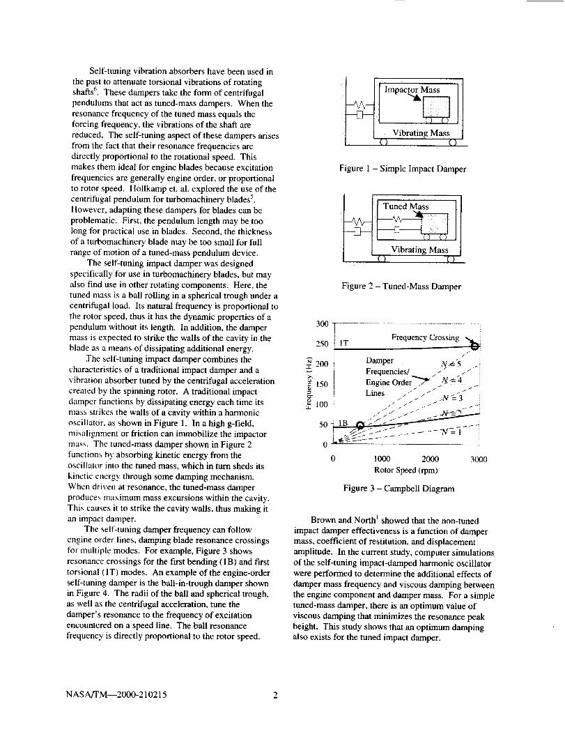
blade as a means of dissipating additional energy.The self-tuning impact damper combines the
characteristics of a traditional impact damper and avibration absorber tuned by the centrifugal acceleration
created by the spinning rotor. A traditional impactdamper functions by dissipating energy each time its
mass strikes the walls of a cavity within a harmonicoscillator, as shown in Figure 1. In a high g-field,
misalignment or friction can immobilize the impactormass. The tuned-mass damper shown in Figure 2
functions by absorbing kinetic energy from theoscillator into the tuned mass, which in turn sheds its
kinetic energy through some damping mechanism.When driven at resonance, the tuned-mass damper
produces maximum mass excursions within the cavity.This causes it to strike the cavity walls, thus making it
an impact damper.The self-tuning damper frequency can follow
engine order lines, damping blade resonance crossingsfor multiple modes. For example, Figure 3 shows
resonance crossings for the first bending (1B) and f'trsttorsional (1 T) modes. An example of the engine-order
self-tuning damper is the ball-in-trough damper shownin Figure 4. The radii of the ball and spherical trough,as well as the centrifugal acceleration, tune the
damper's resonance to the frequency of excitationencountered on a speed line. The ball resonance
frequency is directly proportional to the rotor speed.
Impac 11Vibrating Mass
() ()
Figure 1 - Simple Impact Damper
Tuned Mass ] J
Vibrating Mass
Figure 2 - Tuned-Mass Damper
I250 IT Frequency Crossing
Frequencies/ . -#
_= 150 Engine Order"'_J /y_-4
I f j
Lines _-"............. N t= 3
0
0 1000 2000 3000
Rotor Speed (rpm)
Figure 3 - Campbell Diagram
Brown and North I showed that the non-tuned
impact damper effectiveness is a function of dampermass, coefficient of restitution, and displacement
amplitude. In the current study, computer simulationsof the self-tuning impact-damped harmonic oscillatorwere performed to determine the additional effects of
damper mass frequency and viscous damping betweenthe engine component and damper mass. For a simpletuned-mass damper, there is an optimum value of
viscous damping that minimizes the resonance peakheight. This study shows that an optimum dampingalso exists for the tuned impact damper.
NAS A/TM--2000-210215 2

Figure4- Self-TuningImpact DamperBall-in-Spherical-Trough Design
ANALYSIS
The damped turbomachinery component ismodeled as a two-degree-of-freedom system, as shown
in Figure 4. The mass-spring-damper system representsa vibration mode of the component (primary mass). A
self-tuning impact damper is placed in a cavity within
the primary mass.The analysis technique follows that done by Brown
and North _. The derivation of the equations of motion
is divided into three parts. The first part describes themotion of the primary mass and damper mass between
impacts. In the second part, the behavior of the system
at the time of impact is characterized; impact affects thevelocities of both the primary and damper masses.
Finally, the damper mass can "bounce-down" againstthe cavity wall during a primary mass oscillation. Thisoccurs when the damper mass makes successively
smaller bounces during a primary mass half-cycle,
finally coming to rest against the cavity wall. Ratherthan spending computational time on infinitesimallysmall bounces, it is assumed that the damper massbecomes stuck on the wall when the time between
bounces becomes very small. The equations of motion
during this time represent the primary mass and damper
mass moving as one object.
MOTION BETWEEN IMPACTS
In Figure 4, the primary mass mr represents the
modal mass of the engine component. The parameters
_s and o)s are the damping coefficient and resonancefrequency of that mode in the absence of the dampermass.
The damper mass m2 is a ball of radius r that rolls
without slip inside a spherical trough, or bowl, of radiusR. The acceleration a is the radial acceleration caused
by rotation. This acceleration is a = RoO)ee, where Ro isthe distance of the ball from the center of rotation of the
rotor, and 0)n is the rotor angular velocity. The primary
mass displacement is xdt), and the displacement of theball relative to the bowl in the x-direction is x,.(t).
The natural frequency of a ball rolling without slip
in a trough under rotation is
_. 5Ro('02 = WR 7(R - r)' (1)
assuming small displacements. Since the ball
frequency is directly proportional to the rotationalfrequency, the bali frequency can be designed to follow
an engine order N such that o92= No)e and
-£5R oN = _?(__--r)- (2)
The equations of motion for the primary, mass and
the ball rolling in the bowl are
0+7/'/" -;':-_ +-5(2_"_°')3- 2(l+Hge°92 2,
[ ]{t{;}(.01- --/../0) 2 X 1 = (3)
+ s , (1+ _S -"_"-Trot H
where the mass ratio is H = m2/ms. Here there is noexternal force on the system. It is assumed that there is
some viscous damping between the primary mass and
the damper mass, which is denoted by __,. These
equations differ slightly from the simple pendulumequations since the damper mass rolling effects areincluded.
BEHAVIOR DURING IMPACT
As the ball motion increases, it can strike the wall
of the cavity. The impact behavior is modeled
assuming a simple coefficient of restitution e, andneglecting rotational inertia. Brown and North I show
that the equations governing the behavior at impact are
I< l[l° '1 - It'-,J
where the superscripts - and + denote the propertiesimmediately before and after impact, respectively.
(4)
STUCK DAMPER MASS
When the ball bounces down against the cavitywall during an oscillation, excessive computational
time can be spent on infinitesimally small bounces.Thus, it is assumed that the ball becomes stuck on the
wall when the time between bounces becomes very
NAS A/TM--2000-210215 3
small.Thedampermassandprimarymassthen move E 1.4as a single object. The equations describing this
E 1.2situation are _,
_?/[/ )t I _-0, (5) _ _ 1.024":o, :{ 4 0.8-_l + 1---_ I + 1
.it'-, =0, A2 =0, .v2 =-+_, _ 0.6-
where d is the clearance in the cavity through which the _ 0.4
damper mass can move. These equations are invoked 0.2when the time between successive impacts falls below a 5Zspecified number. 0.0
NUMERICAL ANALYSIS
Both the tuned and the impact nature of thisdamper were studied numerically for this simple two-
degree-of-freedom system. The frequency ratio o.k./to1
and the tuned mass damping 52 were varied to study the
effect on the effective damping coefficient 5, which
will be defined in the following section. The primary
mass damping (1 was set at 0.002 to agree with
previous experimental data 2'3"4. The mass ratio p was
set at 0.003, and the coefficient of restitution e wasassumed to be 0.6.
METHOD
The equations of motion governing the tuned-impact-damped system are nonlinear. Therefore, the
equations were solved numerically with a FORTRANprogram using an adaptable step size Runge-Kutta-
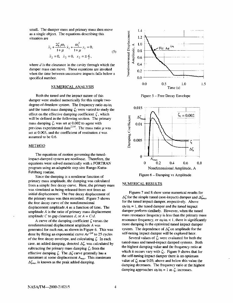
Fehlberg routine.Since the damping is a nonlinear function of
primary mass amplitude, the damping was calculatedfrom a simple free decay curve. Here, the primary masswas simulated as being released from rest from an
initial displacement. The free decay displacement ofthe primary mass was then recorded. Figure 5 shows
the free decay curve of the nondimensional
displacement amplitude A as a function of time. Theamplitude A is the ratio of primary mass displacement
amplitude C to gap clearance d, or A = C/d.
A curve of the damping coefficient _"versus thenondimensional displacement amplitude A was
generated for each run, as shown in Figure 6. This was
done by fitting an exponential curve Ae -(a" to 25 cycles
of the free decay envelope, and calculating 5. In each
case, an added damping, denoted A(, was calculated by
subtracting the primary mass damping (i from the
effective damping _'. The d(curve generally has a
maximum at some displacement Am,_,. This maximum
Ag_a,. is known as the peak added damping.
I ...................... i..............
0.0 0.5 1.0 1.5Time (s)
Figure 5 - Free Decay Envelope
E
EO
¢)
t-
0.015
0.01
0.005
/_max
0 0.2 0.4 0.6 0.8
Nondimensional Amplitude, A
Figure 6 - Damping vs Amplitude
NUMERICAL RESULTS
Figures 7 and 8 show some numerical results for
A(for the simple tuned (non-impact) damper and A(m,_,
for the tuned impact damper, respectively. Above
c.oe/og_= 1, the tuned damper and the tuned impact
damper perform similarly. However, when the tunedmass resonance frequency is less than the primary mass
resonance frequency, or r.oe/tol< 1, there is significantly
more damping in the optimized tuned impact damper
system. The dependence of d_'on amplitude for theself-tuning impact damper will be explored later.
Several values of 5-" were evaluated for both the
tuned-mass and tuned-impact damped systems. Both
the highest damping value and the frequency ratio at
which it occurs vary with 52. Figure 9 shows that for
the self-tuning impact damper there is an optimum
value of 52 near 0.03; above and below this value thedamping decreases. The frequency ratio at the highest
damping approaches ¢oe/co_= 1 as 52 increases.
NASA/TM--2000-210215 4

Note that in Figure 9, when 52 = 0.0 the highest
damping occurs near _/¢ol = 0.8. The ball frequency
does not coincide with the primary mass frequency at
that point. The engineer needs to account for the
expected (2 when designing the damper.
0.030
_.o 0.025<1
"_ 0.020
e,,,
<
.......... i ...................
_P = 0.003, _,- 0.002 i "_ _2 = 0.01
_2 = 0.03 i
0.015 _!0.010
0.005 t _
0.0 0.5 1.0 1.5 2.0
Frequency Ratio, _,j¢.o_
Figure 7 - Tuned-Mass Damper
Added Damping vs Frequency Ratio
-_.he-
7,E
<
0.030
0.025
0.020
0.015
0.010
0.005
0.000
0.0 0.5 1.0 1.5 2.0
Frequency Ratio, o)ffo_l
Figure 8 - Self-Tuning Impact Damper
Added Damping vs Frequency Ratio
Figure 10 shows that for the self-tuning impact
damper, the nondimensional amplitude A,,,_, at which
the peak added damping A_m,_ occurs also varies with
frequency ratio. The amplitude A,,_ corresponding to
the highest damping is very small. This is also
illustrated in Figure 11. Here the added damping is
shown as a function of frequency ratio for various
values of A.
In order to design a damper for a specific
application, the engineer needs to consult a diagram
such as Figure 11. The engineer should know the
expected blade displacement amplitude at the damper
location, and the frequency or frequency range of
interest. If large damping over a small frequency range
is desired, then the damper clearance d should be
chosen to give a very small A, in this case around 0.05.
If damping over a larger frequency range is desired,
then d should be chosen to give a moderate value of A,
in this case around 0.10.
0.030 ] .............................. 1.2
I ohlo_I
o.02510.020 i
i [ _,a0.015
"E.E
"o
<
Y.
O.OLO B = 0.003
_l = 0.0020.005
e=0.6
0,00O i 0.0
0.00 0.02 0.04 0.06
Damping Coefficient '_.,
Figure 9 - Optimum Damping and Frequency Ratio
vs Damping Coefficient 52
0.0 0.5 1.0 1.5
Frequency Ratio, o._,jo_
Figure 10 - Nondimensional Amplitude A at
Peak Added Damping
2.0
0.016
0.014
0.012<]
_5 0.010_.
?. 0.0o80.0o6
0.004
0.002
o.ooo
t g = 0.003
ooo2= 0.030
e=0.6
A = 0.50
"I_A = 0.15
tA=0.10
A = 0.05
0.0 0.5 1.0 1.5
Frequency Ratio. _o2/°)_
Figure 1 1 -A_ for Constant Nondimensional
Amplitude, A - Case: 52 = 0.03
NASA/TM--2000-210215 5
EXPERIMENTAL VALIDATION
The theoretical results for free decay behavior have
been validated by experiments in the Dynamic Spin2:_4
Facility at NASA Glenn Research center ".
EXPERIMENTAL SETUP
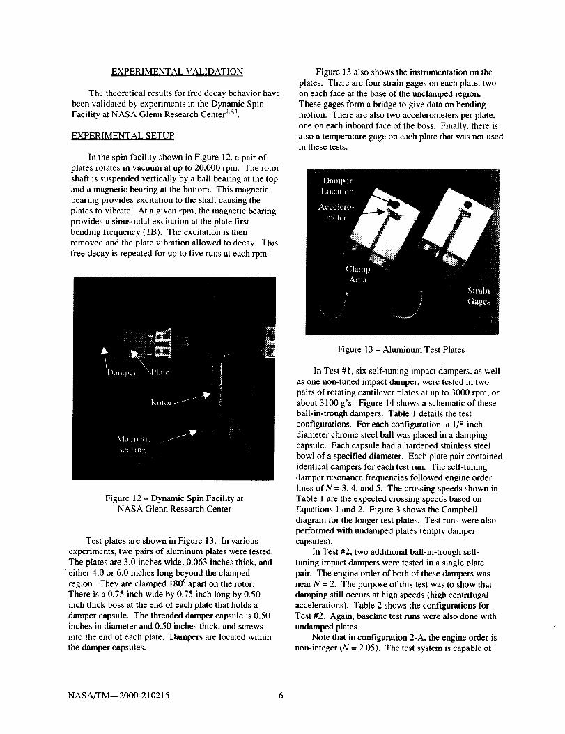
In the spin facility shown in Figure 12, a pair ofplates rotates in vacuum at up to 20,000 rpm. The rotor
shaft is suspended vertically by a ball bearing at the topand a magnetic bearing at the bottom. This magnetic
bearing provides excitation to the shaft causing theplates to vibrate. At a given rpm, the magnetic bearing
provides a sinusoidal excitation at the plate firstbending frequency (1B). The excitation is then
removed and the plate vibration allowed to decay. Thisfree decay is repeated for up to five runs at each rpm.
Figure 13 also shows the instrumentation on the
plates. There are four strain gages on each plate, twoon each face at the base of the unclamped region.These gages form a bridge to give data on bending
motion. There are also two accelerometers per plate,
one on each inboard face of the boss. Finally, there isalso a temperature gage on each plate that was not usedin these tests.
Figure 12 - Dynamic Spin Facility atNASA Glenn Research Center
Test plates are shown in Figure 13. In various
experiments, two pairs of aluminum plates were tested.The plates are 3.0 inches wide, 0.063 inches thick, and
'either 4.0 or 6.0 inches long beyond the clampedregion. They are clamped 180 ° apart on the rotor.
There is a 0.75 inch wide by 0.75 inch long by 0.50inch thick boss at the end of each plate that holds a
damper capsule. The threaded damper capsule is 0.50inches in diameter and 0.50 inches thick, and screws
into the end of each plate. Dampers are located withinthe damper capsules.
Figure 13 - Aluminum Test Plates
In Test #1, six self-tuning impact dampers, as well
as one non-tuned impact damper, were tested in twopairs of rotating cantilever plates at up to 3000 rpm, orabout 3100 g's. Figure 14 shows a schematic of these
ball-in-trough dampers. Table I details the test
configurations. For each configuration, a 1/8-inchdiameter chrome steel ball was placed in a dampingcapsule. Each capsule had a hardened stainless steel
bowl of a specified diameter. Each plate pair containedidentical dampers for each test run. The self-tuning
damper resonance frequencies followed engine order
lines of N = 3, 4, and 5. The crossing speeds shown inTable 1 are the expected crossing speeds based on
Equations 1 and 2. Figure 3 shows the Campbelldiagram for the longer test plates. Test runs were alsoperformed with undamped plates (empty damper
capsules).In Test #2, two additional ball-in-trough self-
tuning impact dampers were tested in a single plate
pair. The engine order of both of these dampers wasnear N = 2. The purpose of this test was to show that
damping still occurs at high speeds (high centrifugalaccelerations). Table 2 shows the configurations forTest #2. Again, baseline test runs were also done with
undamped plates.Note that in configuration 2-A, the engine order is
non-integer (N = 2.05). The test system is capable of
NASA/TM--2000-210215 6
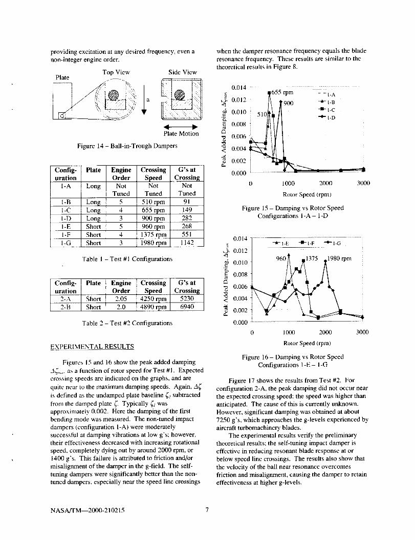
providingexcitationatanydesiredfrequency,evenanon-integerengineorder.
TopView SideViewPlate
PlateMotion
Figure14- Ball-in-TroughDampers
Config-uration
I-A
1-B
1-C
I-D
I-E
I-F
I-G
Config-uration
2-A
2-B
Plate EngineOrder
Long NotTuned
Long 5
Lon_ 4
Lon$ 3Short 5
Short 4
Short 3
Crossing
SpeedNot
Tuned
510rpm
655rpm
900rpm
960rpm
1375rpm
1980rpm
G's at
CrossingNot
Tuned
91
149
282
268
551
1142
Table 1 - Test #1 Configurations
Plate
Short
Short
EngineOrder2.05
2.0
Crossing G's at
Speed Crossing
4250rpm 52304890rpm 6940
Table 2 - Test #2 Configurations
EXPERIMENTAL RESULTS
Figures 15 and 16 show the peak added damping
.3_, ..... as a function of rotor speed for Test #1. Expected
crossing speeds are indicated on the graphs, and are
quite near to the maximum damping speeds. Again, A_
is defined as the undamped plate baseline _ subtracted
from the damped plate 5- Typically _i was
approximately 0.002. Here the damping of the firstbending mode was measured. The non-tuned impact
dampers (configuration l-A) were moderately
successful at damping vibrations at low g's; however,their effectiveness decreased with increasing rotational
speed, completely dying out by around 2000 rpm, or
1400 g's. This failure is attributed to friction and/ormisalignment of the damper in the g-field. The self-
tuning dampers were significantly better than the non-tuned dampers, especially near the speed line crossings
when the damper resonance frequency equals the blade
resonance frequency. These results are similar to the
theoretical results in Figure 8.
0.014 [........ ]_655 rpm - -_ilA .......
< 0.012! It 1900i L1 il -a-l-c _
=_ 0.010 510_[i_ / I0.008
__ o.006 _
< 0.004
0.002
0.000
0 1000 2000 3000
Rotor Speed (rpm)
Figure 15 - Damping vs Rotor SpeedConfigurations 1-A- I-D
E
0.014•"it- 1-E --m- I-F + 1-G
0.012
0.010 960 1:
0.008
0.006
0.004
0.002
0.000 I
0 1000 2000 3000
Rotor Speed (rpm)
Figure 16- Damping vs Rotor SpeedConfigurations l-E- I-G
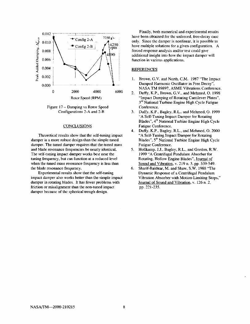
Figure 17 shows the results from Test #2. Forconfiguration 2-A, the peak damping did not occur near
the expected crossing speed; the speed was higher thananticipated. The cause of this is currently unknown.
However, significant damping was obtained at about7250 g's, which approaches the g-levels experienced by
aircraft turbomachinery blades.The experimental results verify the preliminary
theoretical results; the self-tuning impact damper is
effective in reducing resonant blade response at or
below speed line crossings. The results also show that
the velocity of the ball near resonance overcomesfriction and misalignment, causing the damper to retaineffectiveness at higher g-levels.
NASA/TM--2000-210215 7
0.012
E
_-_ 0.010<_
.E 0.008e_
E0.006
--o 0.004<
0.002
0.000
1\ ! -_Config 2-B j f/_l_ 50!:
,0 2000 4000 6000
Rotor Speed (RPM)
Figure 17 - Damping vs Rotor Speed
Configurations 2-A and 2-B
CONCLUSIONS
Theoretical results show that the self-tuning impactdamper is a more robust design than the simple tuned
damper. The tuned damper requires that the tuned massand blade resonance frequencies be nearly identical.The self-tuning impact damper works best near the
tuning frequency, but can function at a reduced levelwhen the tuned mass resonance frequency is less than
the blade resonance frequency.Experimental results show that the self-tuning
impact damper also works better than the simple impactdamper in rotating blades. It has fewer problems with
friction or misalignment than the non-tuned impactdamper because of the spherical trough design.
Finally, both numerical and experimental resultshave been obtained for the unforced, free-decay case
only. Since the damper is nonlinear, it is possible tohave multiple solutions for a given configuration. A
forced response analysis and/or test could giveadditional insight into how the impact damper will
function in various applications.
REFERENCES
1. Brown, G.V. and North, C.M. 1987 "The ImpactDamped Harmonic Oscillator in Free Decay",NASA TM 89897, ASME Vibrations Conference.
2. Duffy, K.P., Brown, G.V., and Mehmed, O. 1998
"Impact Damping of Rotating Cantilever Plates",3_dNational Turbine Engine High Cycle FatigueConference.
3. Duffy, K.P., Bagley, R.L., and Mehmed, O. 1999
"A Self-Tuning Impact Damper for RotatingBlades", 4 th National Turbine Engine High Cycle
Fatigue Conference.4. Duffy, K.P., Bagley, R.L., and Mehmed, O. 2000
"A Self-Tuning Impact Damper for RotatingBlades", 5 th National Turbine Engine High Cycle
Fatigue Conference.5. Hollkamp, J.J., Bagley, R.L., and Gordon, R.W.
1999 "A Centrifugal Pendulum Absorber forRotating, Hollow Engine Blades", Journal of
Sound and Vibration, v. 219 n. 3, pp. 539-549.6. Sharif-Bakhtar, M. and Shaw, S.W. 1988 "The
Dynamic Response of a Centrifugal PendulumVibration Absorber with Motion-Limiting Stops,"Journal of Sound and Vibration v. 126 n. 2,
pp. 221-235.
NASAfI'M--2000-210215 8


REPORT DOCUMENTATION PAGE FormApprovedOMB No. 0704-0188
Public reporting burden for this collection of information is estimated to average 1 hour per response, including the time for reviewing instructions, searching existing data sources,
gathering and maintaining the data needed, and completing and reviewing the collection of information. Send comments regarding this burden estimate or any other aspect of this
collection of information, including suggestions for reducing this burden, to Washington Headquarters Services, Directorate for Information Operations and Reports, 1215 Jeffe!son
Davis Highway, Suite 1204, Arlington, VA 22202-4302, and to the Office of Management and Budget, Paperwork Reduction Project (0704-0188), Washington, DC 20503,
1. AGENCY USE ONLY (Leave blank) 2. REPORT DATE 3. REPORT TYPE AND DATES COVERED
August 2000 Technical Memorandum
4. TITLE AND SUBTITLE
On a Self-Tuning Impact Vibration Damper for Rotating Turbomachinery
6. AUTHOR(S)
Kirsten P. Duffy, Ronald L. Bagley, and Oral Mehmed
7. PERFORMING ORGANIZATION NAME(S) AND ADDRESS(ES)
National Aeronautics and Space Administration
John H. Glenn Research Center at Lewis Field
Cleveland, Ohio 44135-3191
9. SPONSORING/MONITORING AGENCY NAME(S) AND ADDRESS(ES)
National Aeronautics and Space Administration
Washington, DC 20546-0001
5. FUNDING NUMBERS
WU-274-4)04)(O_
8. PERFORMING ORGANIZATIONREPORT NUMBER
E-12334
10. SPONSORING/MONITORINGAGENCY REPORTNUMBER
NASA TM--2000-210215
11. SUPPLEMENTARY NOTES
Prepared for the Joint Propulsion Conference sponsored by the American Institute of Aeronautics and Astronautics, Huntsville, Alabama,
July 17-19, 2000. Kirsten P. Duffy, Ohio Aerospace Institute, 22800 Cedar Point Road, Brook Park, Ohio 44142 (work funded under
NASA Cooperative Agreement NCC3-724): Ronald L. Bagley, Associate Professor, University of Texas at San Antonio, San Antonio,
Texas 78249-1130: and Oral Mehmed, Senior Research Engineer, NASA Glenn Research Center. Responsible person, Ben Choi,
organization code 5930, (216) 433--6040.
12a. DISTRIBUTION/AVAILABILITY STATEMENT
Unclassified - Unlimited
Subject Categories: 07 and 39 Distribution: Nonstandard
This publication is available from the NASA Center for AeroSpace Information, (301 ) 621-0390.13. ABSTRACT (Maximum 200 words)
12b. DISTRIBUTION CODE
A self-tuning impact damper is investigated analytically and experimentally as a device to inhibit vibration and increase
the fatigue life of rotating components in turbomachinery. High centrifugal loads in rotors can inactivate traditional
impact dampers because of friction or misalignment of the damper in the g-field. Giving an impact damper characteris-
tics of an acceleration tuned-mass damper enables the resulting device to maintain damper mass motion and effectiveness
during high-g loading. Experimental results presented here verify that this self-tuning impact damper can be designed to
follow an engine order line, damping rotor component resonance crossings.
14. SUBJECT TERMS
Turbomachine blades; Vibration damping; Spin tests
17. SECURITY CLASSIFICATIONOF REPORT
Unclassified
18. SECURITY CLASSIFICATIONOF THIS PAGE
Unclassified
NSN 7540-01-280-5500
19. SECURITY CLASSIFICATIONOF ABSTRACT
Unclassified
15. NUMBER OFPAGES
1416. PRICE CODE
20. LIMITATION OF ABSTRACT
Standard Form 298 (Rev. 2-89)Prescribed by ANSI Std. Z39-18
298-102


![Assessing the effect of nonlinearities on the performance ... · a tuned viscous mass damper, where an inerter is used as a mass amplifier. In [11], the effectiveness of the tuned](https://img.pdfslide.net/doc/110x75/6021da326b0bfb6f770c2c00/assessing-the-effect-of-nonlinearities-on-the-performance-a-tuned-viscous-mass.jpg)