Embed Size (px)
Citation preview
HydraForce Inc. August 20, 2013 Page 1
HydraForce PFPD assembly
HydraForce Incorporated
Henry Brewer
HydraForce Inc. August 20, 2013 Page 2
About
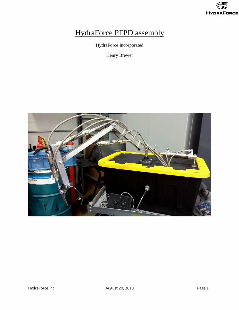
The HydraForce Portable Fluid Power Demonstrator was designed and built to showcase
hydraulics and introduce people to fluid power using the unit as a demonstrator and an
educational tool. The unit itself is a small sized, electronically controlled, self-contained, claw
arm capable of demonstration with a limited range of motion.
Much of this guide will be based off of the Portable Fluid Power Demonstrator (PFPD) v.2 –
Electronic Control Arm Trainer which was done by the Center for Compact and Efficient Fluid
Power and Purdue University. A link to the initial project can be found here. Direct excerpts
from the assembly document will be used in this document.
A comprehensive parts list can be found at the end of these instructions including parts needed,
quantities, and links to purchasing where applicable.
The fabrication and assembly in this guide are open to changes and modifications, and for each
step there are many ways to go about it. This guide will attempt to cover all of the methods you
can use, but will focus on the methods used in the initial construction.
HydraForce Inc. August 20, 2013 Page 3
Arm and Claw Fabrication
This step goes through the sub-steps to make the Arm and Claw. Recommended metal
machining tools including: a drill press, a band saw, and a vice as well as basic tools such as
hammers, files, and a hack saw. Dimensions can be inferred using all of the following pictures.
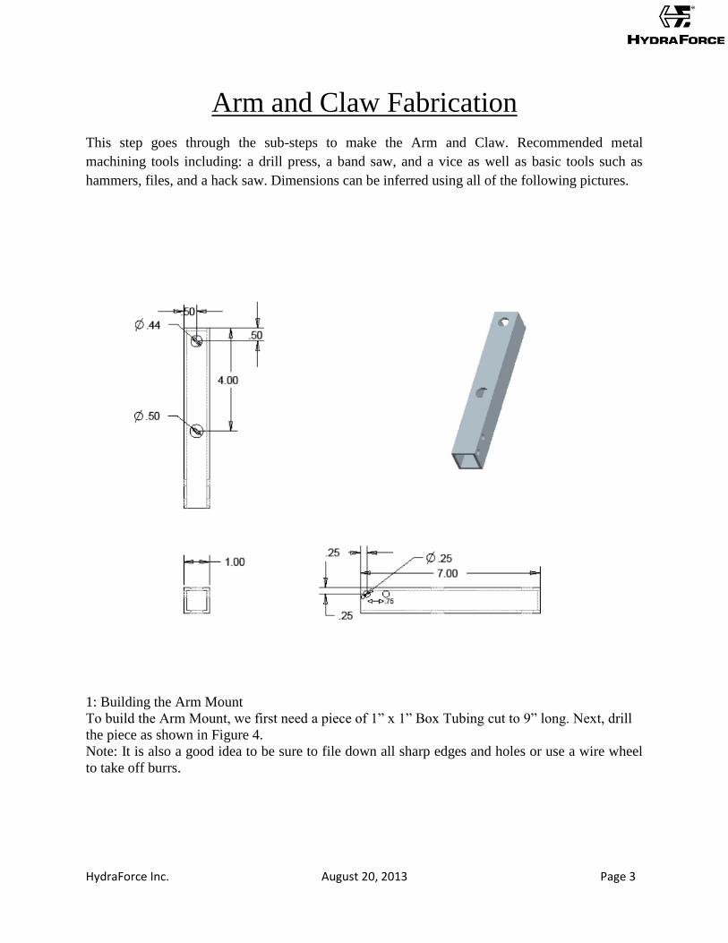
1: Building the Arm Mount
To build the Arm Mount, we first need a piece of 1” x 1” Box Tubing cut to 9” long. Next, drill
the piece as shown in Figure 4.
Note: It is also a good idea to be sure to file down all sharp edges and holes or use a wire wheel
to take off burrs.
HydraForce Inc. August 20, 2013 Page 4
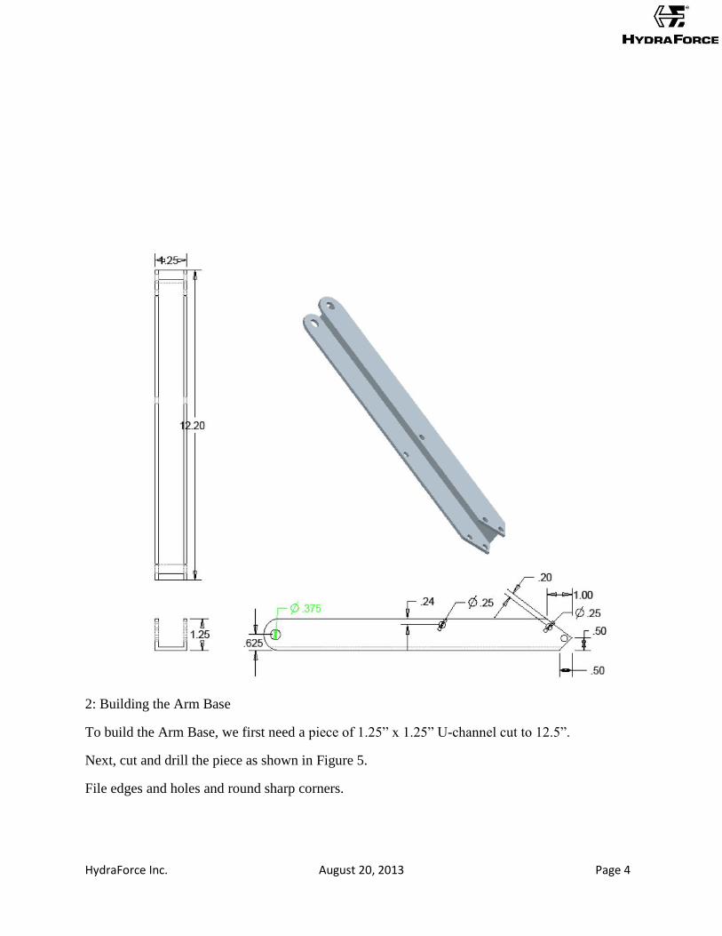
2: Building the Arm Base
To build the Arm Base, we first need a piece of 1.25” x 1.25” U-channel cut to 12.5”.
Next, cut and drill the piece as shown in Figure 5.
File edges and holes and round sharp corners.
HydraForce Inc. August 20, 2013 Page 5
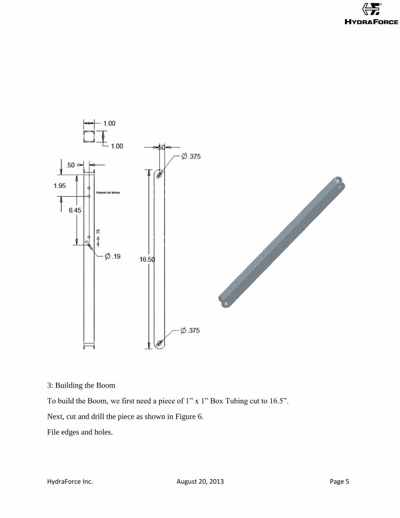
3: Building the Boom
To build the Boom, we first need a piece of 1” x 1” Box Tubing cut to 16.5”.
Next, cut and drill the piece as shown in Figure 6.
File edges and holes.
HydraForce Inc. August 20, 2013 Page 6
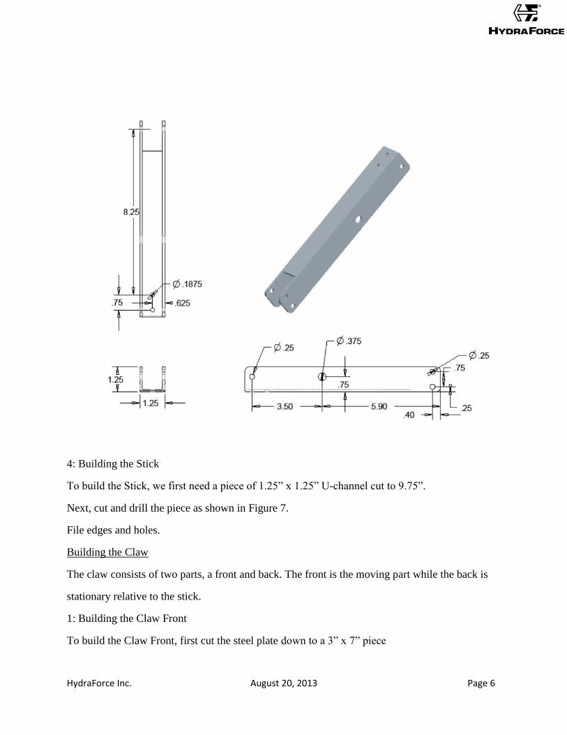
4: Building the Stick
To build the Stick, we first need a piece of 1.25” x 1.25” U-channel cut to 9.75”.
Next, cut and drill the piece as shown in Figure 7.
File edges and holes.
Building the Claw
The claw consists of two parts, a front and back. The front is the moving part while the back is
stationary relative to the stick.
1: Building the Claw Front
To build the Claw Front, first cut the steel plate down to a 3” x 7” piece
HydraForce Inc. August 20, 2013 Page 7
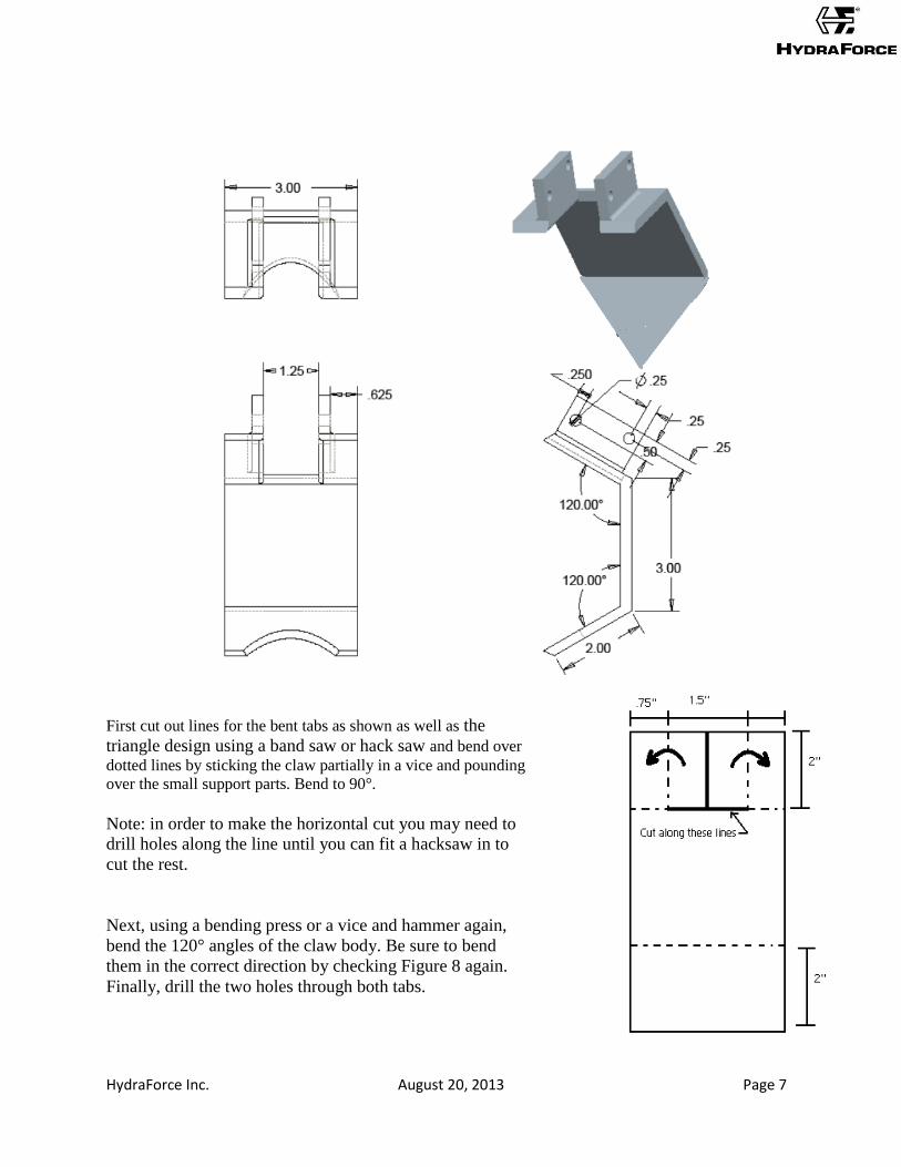
First cut out lines for the bent tabs as shown as well as the
triangle design using a band saw or hack saw and bend over
dotted lines by sticking the claw partially in a vice and pounding
over the small support parts. Bend to 90°.
Note: in order to make the horizontal cut you may need to
drill holes along the line until you can fit a hacksaw in to
cut the rest.
Next, using a bending press or a vice and hammer again,
bend the 120° angles of the claw body. Be sure to bend
them in the correct direction by checking Figure 8 again.
Finally, drill the two holes through both tabs.
HydraForce Inc. August 20, 2013 Page 8
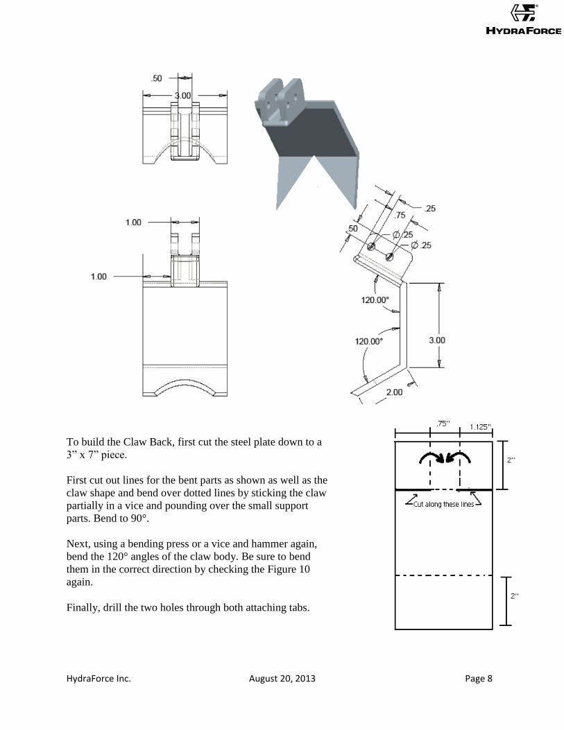
To build the Claw Back, first cut the steel plate down to a
3” x 7” piece.
First cut out lines for the bent parts as shown as well as the
claw shape and bend over dotted lines by sticking the claw
partially in a vice and pounding over the small support
parts. Bend to 90°.
Next, using a bending press or a vice and hammer again,
bend the 120° angles of the claw body. Be sure to bend
them in the correct direction by checking the Figure 10
again.
Finally, drill the two holes through both attaching tabs.
HydraForce Inc. August 20, 2013 Page 9
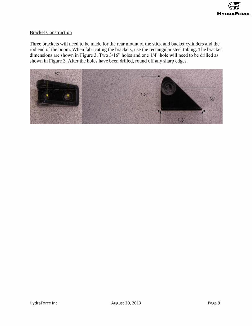
Bracket Construction
Three brackets will need to be made for the rear mount of the stick and bucket cylinders and the
rod end of the boom. When fabricating the brackets, use the rectangular steel tubing. The bracket
dimensions are shown in Figure 3. Two 3/16” holes and one 1/4” hole will need to be drilled as
shown in Figure 3. After the holes have been drilled, round off any sharp edges.
HydraForce Inc. August 20, 2013 Page 10
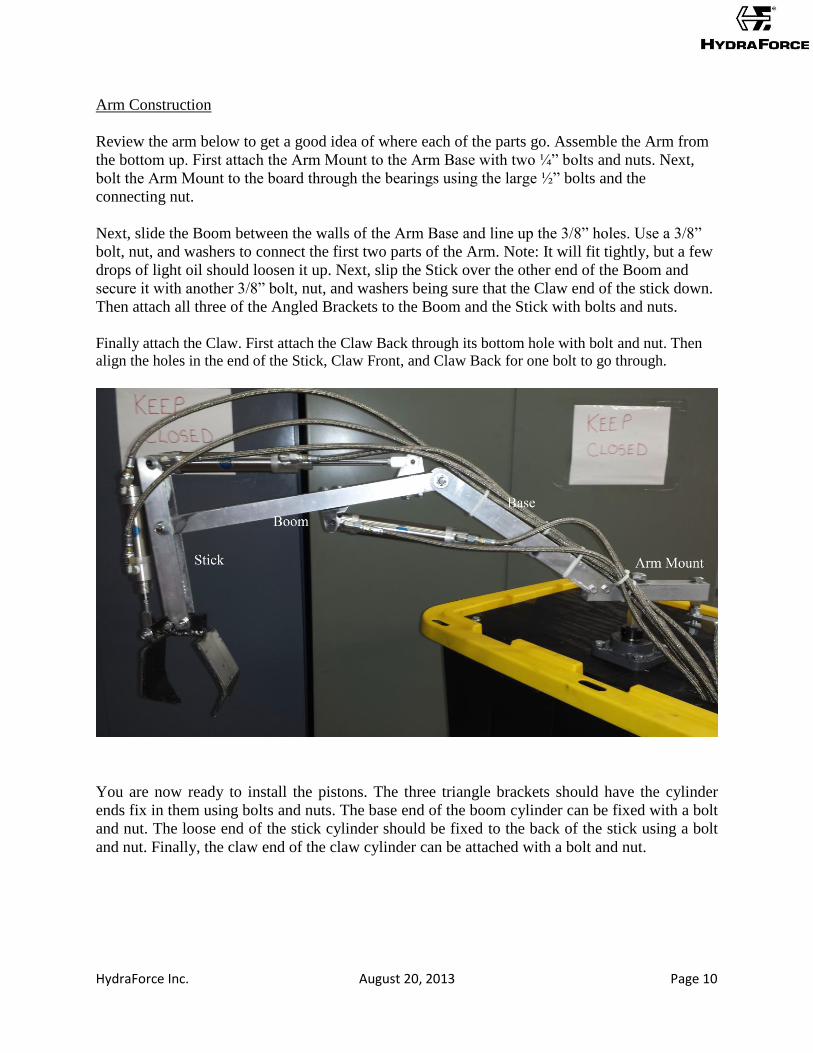
Arm Construction
Review the arm below to get a good idea of where each of the parts go. Assemble the Arm from
the bottom up. First attach the Arm Mount to the Arm Base with two ¼” bolts and nuts. Next,
bolt the Arm Mount to the board through the bearings using the large ½” bolts and the
connecting nut.
Next, slide the Boom between the walls of the Arm Base and line up the 3/8” holes. Use a 3/8”
bolt, nut, and washers to connect the first two parts of the Arm. Note: It will fit tightly, but a few
drops of light oil should loosen it up. Next, slip the Stick over the other end of the Boom and
secure it with another 3/8” bolt, nut, and washers being sure that the Claw end of the stick down.
Then attach all three of the Angled Brackets to the Boom and the Stick with bolts and nuts.
Finally attach the Claw. First attach the Claw Back through its bottom hole with bolt and nut. Then
align the holes in the end of the Stick, Claw Front, and Claw Back for one bolt to go through.
You are now ready to install the pistons. The three triangle brackets should have the cylinder
ends fix in them using bolts and nuts. The base end of the boom cylinder can be fixed with a bolt
and nut. The loose end of the stick cylinder should be fixed to the back of the stick using a bolt
and nut. Finally, the claw end of the claw cylinder can be attached with a bolt and nut.
HydraForce Inc. August 20, 2013 Page 11
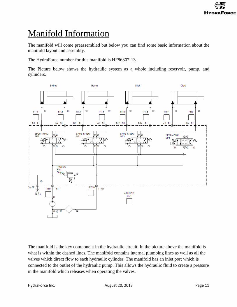
Manifold Information The manifold will come preassembled but below you can find some basic information about the
manifold layout and assembly.
The HydraForce number for this manifold is HF86307-13.
The Picture below shows the hydraulic system as a whole including reservoir, pump, and
cylinders.
The manifold is the key component in the hydraulic circuit. In the picture above the manifold is
what is within the dashed lines. The manifold contains internal plumbing lines as well as all the
valves which direct flow to each hydraulic cylinder. The manifold has an inlet port which is
connected to the outlet of the hydraulic pump. This allows the hydraulic fluid to create a pressure
in the manifold which releases when operating the valves.
HydraForce Inc. August 20, 2013 Page 12
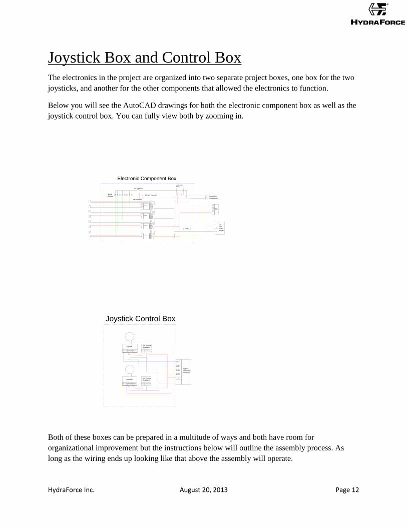
Joystick Box and Control Box The electronics in the project are organized into two separate project boxes, one box for the two
joysticks, and another for the other components that allowed the electronics to function.
Below you will see the AutoCAD drawings for both the electronic component box as well as the
joystick control box. You can fully view both by zooming in.
EVDR0201
1
Power in -
Ground
Power in +
Signal in
Sol B -
Sol B +Sol
A +
Sol
A -
EVDR0201
2
Power in -
Ground
Power in +
Signal in
Sol B -
Sol B +Sol
A +
Sol
A -
EVDR0201
3
Power in -
Ground
Power in +
Signal in
Sol B -
Sol B +Sol
A +
Sol
A -
EVDR0201
4
Power in -
Ground
Power in +
Signal in
Sol B -
Sol B +Sol
A +
Sol
A -
U/D 1
U/D 2
L/R 1
L/R 2
Joystick
control box
connector
12
Volt
Power
Supply
+
-
+
-
FUSE
Solid-State
Relay
Pump-Motor
Combination
Electronic Component Box
100 O Resistor
1 K O Resistor
100 µ F CapacitorSignal
Diodes
U/D 1
U/D 2
L/R 1
L/R 2
Joystick
control box
connector
+
-
12V inGround5v outLR+UD+GNDGND
Joystick 15 V Voltage
Regulator
L/RU/D
12V inGround5v outLR+UD+GNDGND
Joystick 25 V Voltage
Regulator
L/RU/D
Joystick Control Box
Both of these boxes can be prepared in a multitude of ways and both have room for
organizational improvement but the instructions below will outline the assembly process. As
long as the wiring ends up looking like that above the assembly will operate.

HydraForce Inc. August 20, 2013 Page 13
This is a picture of the joystick control box. Two small holes have been dremelled out of the top
of the box to allow movement of the joysticks. A Small LED power indicator has been mounted
to the top and linked directly to the incoming power and ground wires.
This is a picture of the inside of the joystick control box. All wires are soldered to a wire which
carries 8 connections out of the box.
HydraForce Inc. August 20, 2013 Page 14
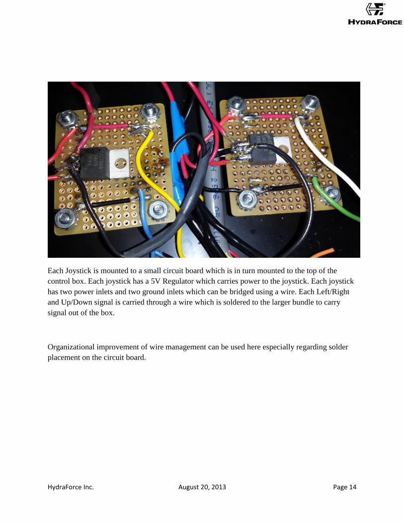
Each Joystick is mounted to a small circuit board which is in turn mounted to the top of the
control box. Each joystick has a 5V Regulator which carries power to the joystick. Each joystick
has two power inlets and two ground inlets which can be bridged using a wire. Each Left/Right
and Up/Down signal is carried through a wire which is soldered to the larger bundle to carry
signal out of the box.
Organizational improvement of wire management can be used here especially regarding solder
placement on the circuit board.
HydraForce Inc. August 20, 2013 Page 15
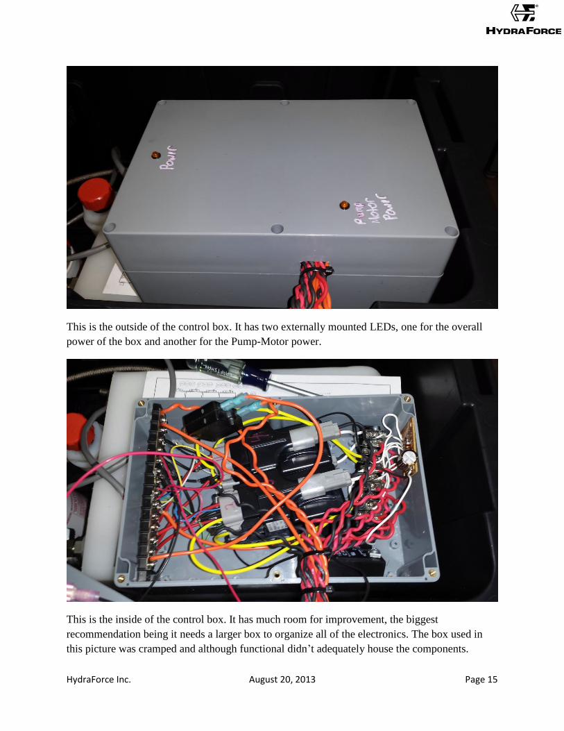
This is the outside of the control box. It has two externally mounted LEDs, one for the overall
power of the box and another for the Pump-Motor power.
This is the inside of the control box. It has much room for improvement, the biggest
recommendation being it needs a larger box to organize all of the electronics. The box used in
this picture was cramped and although functional didn’t adequately house the components.
HydraForce Inc. August 20, 2013 Page 16
The basic idea of the control box was to power all of the EVDRs, ground all of the EVDRs,
collect the signal from all of the EVDRs to send activate a relay, and power the Pump Motor
when the relay is activated.
To power and ground everything in the control box a terminal strip was used.
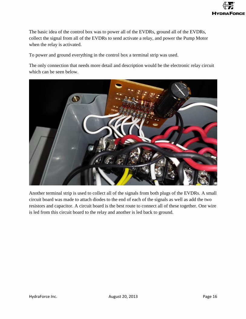
The only connection that needs more detail and description would be the electronic relay circuit
which can be seen below.
Another terminal strip is used to collect all of the signals from both plugs of the EVDRs. A small
circuit board was made to attach diodes to the end of each of the signals as well as add the two
resistors and capacitor. A circuit board is the best route to connect all of these together. One wire
is led from this circuit board to the relay and another is led back to ground.
HydraForce Inc. August 20, 2013 Page 17
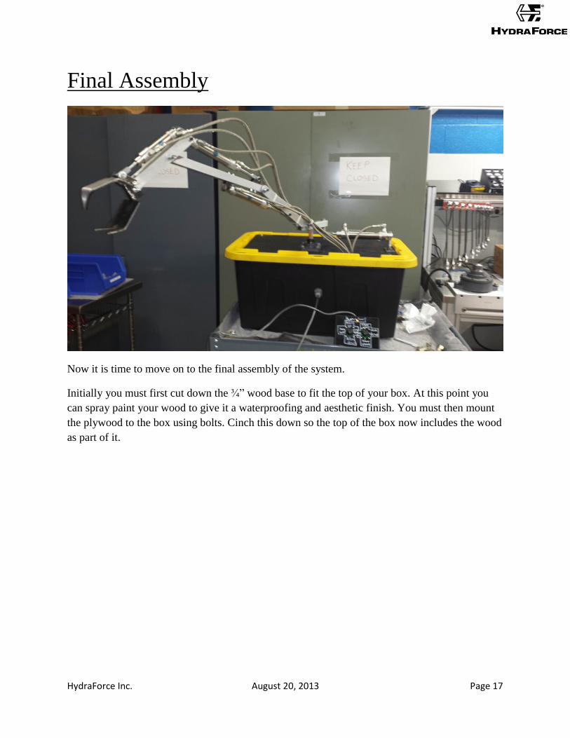
Final Assembly
Now it is time to move on to the final assembly of the system.
Initially you must first cut down the ¾” wood base to fit the top of your box. At this point you
can spray paint your wood to give it a waterproofing and aesthetic finish. You must then mount
the plywood to the box using bolts. Cinch this down so the top of the box now includes the wood
as part of it.
HydraForce Inc. August 20, 2013 Page 18
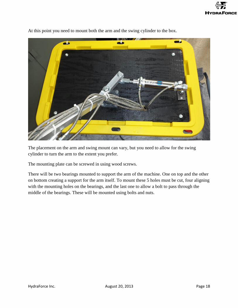
At this point you need to mount both the arm and the swing cylinder to the box.
The placement on the arm and swing mount can vary, but you need to allow for the swing
cylinder to turn the arm to the extent you prefer.
The mounting plate can be screwed in using wood screws.
There will be two bearings mounted to support the arm of the machine. One on top and the other
on bottom creating a support for the arm itself. To mount these 5 holes must be cut, four aligning
with the mounting holes on the bearings, and the last one to allow a bolt to pass through the
middle of the bearings. These will be mounted using bolts and nuts.
HydraForce Inc. August 20, 2013 Page 19
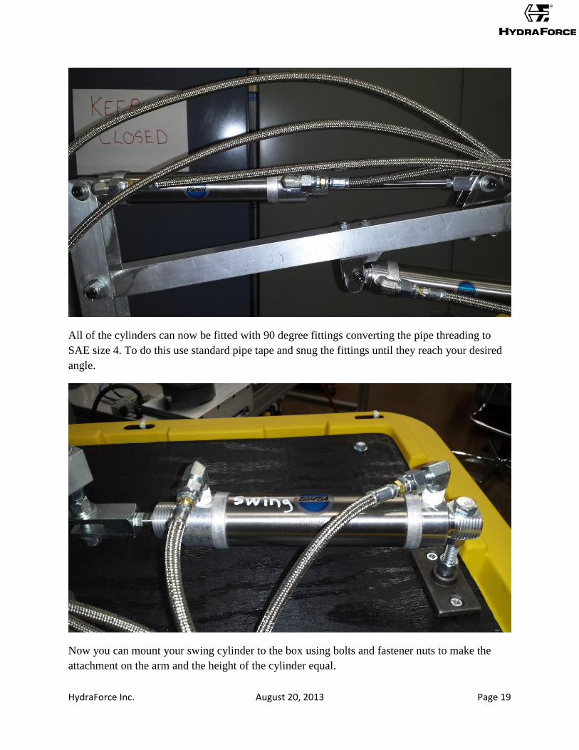
All of the cylinders can now be fitted with 90 degree fittings converting the pipe threading to
SAE size 4. To do this use standard pipe tape and snug the fittings until they reach your desired
angle.
Now you can mount your swing cylinder to the box using bolts and fastener nuts to make the
attachment on the arm and the height of the cylinder equal.
HydraForce Inc. August 20, 2013 Page 20
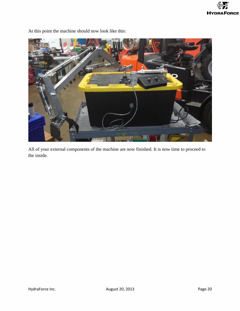
At this point the machine should now look like this:
All of your external components of the machine are now finished. It is now time to proceed to
the inside.
HydraForce Inc. August 20, 2013 Page 21
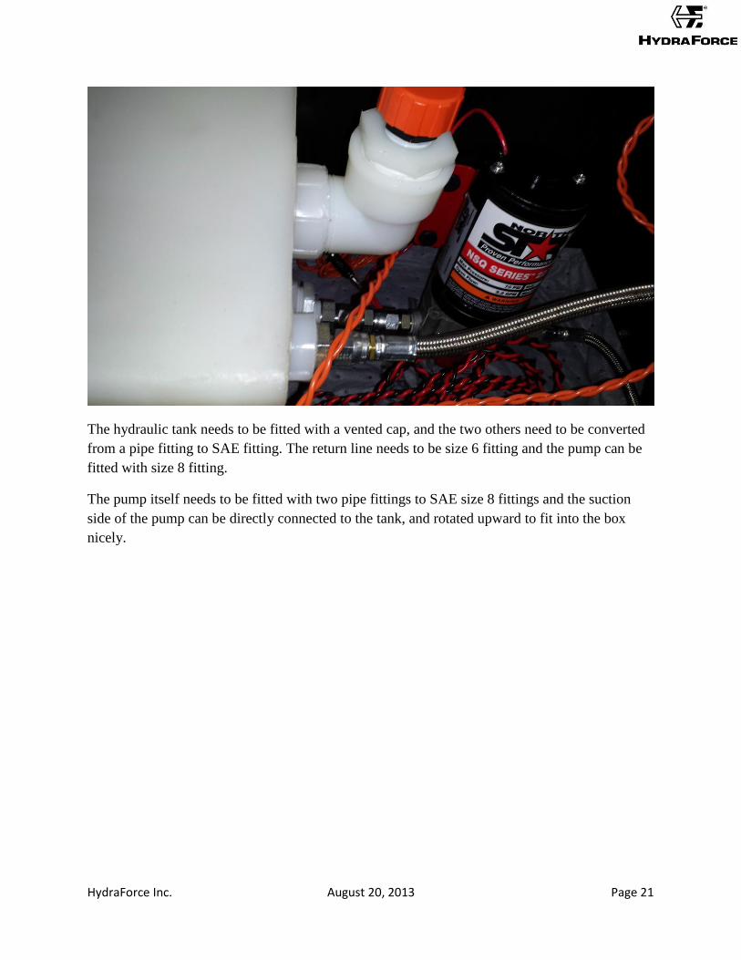
The hydraulic tank needs to be fitted with a vented cap, and the two others need to be converted
from a pipe fitting to SAE fitting. The return line needs to be size 6 fitting and the pump can be
fitted with size 8 fitting.
The pump itself needs to be fitted with two pipe fittings to SAE size 8 fittings and the suction
side of the pump can be directly connected to the tank, and rotated upward to fit into the box
nicely.

HydraForce Inc. August 20, 2013 Page 22
This is going to be the overall layout from the inside of the box. At this point you can start
inserting the tank with connected pump into the corner furthest away from the hydraulic arm. In
my project I used two 2x2’s to raise the tank and mounted it using industrial strength Velcro so
the system can be moved and tweaked still. The control box can be mounted in the corner next to
the tank vertically and the plug from the control box can be mounted to the outside of the box to
allow a disconnect from the joystick control box. The power supply is then mounted into the
opposing corner with a hole in the box placed so you can have the power cord externally. The
manifold can be placed on top and will rest on the bottom of the box secured by all of the hosing
that will be connected next, but so that you can open the box and troubleshoot without having to
redo the system. All of your wired connections from the control box can now be made, including
the signal from the EVDRs, the power source, and the power source for the pump-motor.
The next step is to hose the system and manifold. You must first step the port sizes for the hosing
down from size 6 to size 4 SAE. You can then begin hosing the system from the outside in. It can
be attached in any order but each valve must control both directions on the same cylinder.
HydraForce Inc. August 20, 2013 Page 23
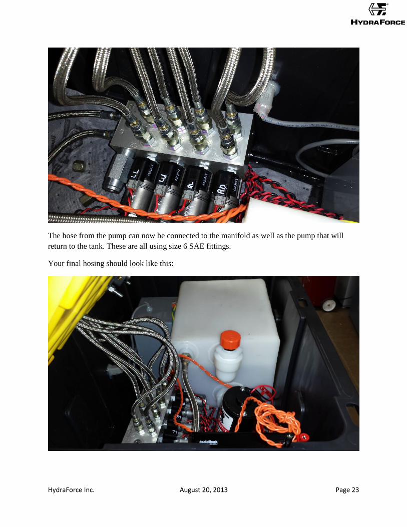
The hose from the pump can now be connected to the manifold as well as the pump that will
return to the tank. These are all using size 6 SAE fittings.
Your final hosing should look like this:
HydraForce Inc. August 20, 2013 Page 24
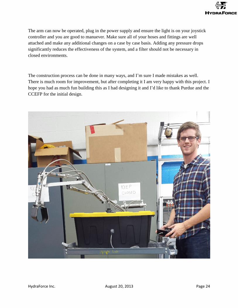
The arm can now be operated, plug in the power supply and ensure the light is on your joystick
controller and you are good to manuever. Make sure all of your hoses and fittings are well
attached and make any additional changes on a case by case basis. Adding any pressure drops
significantly reduces the effectiveness of the system, and a filter should not be necessary in
closed environments.
The construction process can be done in many ways, and I’m sure I made mistakes as well.
There is much room for improvement, but after completing it I am very happy with this project. I
hope you had as much fun building this as I had designing it and I’d like to thank Purdue and the
CCEFP for the initial design.
HydraForce Inc. August 20, 2013 Page 25
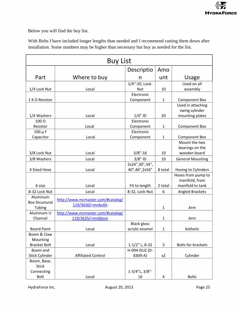
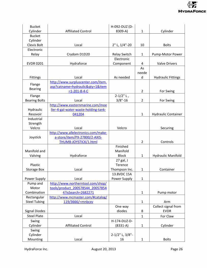
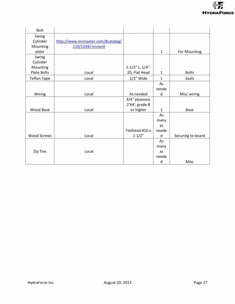
Below you will find the buy list.
With Bolts I have included longer lengths than needed and I recommend cutting them down after
installation. Some numbers may be higher than necessary but buy as needed for the list.
Buy List
Part Where to buy Descriptio
n Amount Usage
1/4 Lock Nut Local 1/4"-20, Lock-
Nut 10 Used on all assembly
1 K O Resistor Electronic
Component 1 Component Box
1/4 Washers Local 1/4" ID 20
Used in attaching swing sylinder
mounting plates
100 O Resistor Local
Electronic Component 1 Component Box
100 μ F Capacitor Local
Electronic Component 1 Component Box
3/8 Lock Nut Local 3/8"-16 10
Mount the two bearings on the wooden board
3/8 Washers Local 3/8" ID 10 General Mounting
4 Sized Hose Local 2x24",30",34",40",46",2x56" 8 total Hosing to Cylinders
6 size Local Fit to length 2 total
Hoses from pump to manifold, from
manifold to tank
8-32 Lock Nut Local 8-32, Lock-Nut 6 Angled Brackets
Aluminum Box Structural
Tubing
http://www.mcmaster.com/#catalog/119/3630/=mnbc6h
1 Arm
Aluminum U Channel
http://www.mcmaster.com/#catalog/119/3635/=mnbbsm 1 Arm
Board Paint Local Black gloss
acrylic enamel 1 Asthetic
Boom & Claw Mounting
Bracket Bolt Local 1-1/2" L, 8-32 3 Bolts for brackets
Boom and Stick Cylinder Affiliated Control
H-094-DUZ (D-8309-A) x2 Cylinder
Boom, Base, Stick
Connecting Bolt Local
1-3/4”L, 3/8”-16 4 Bolts
HydraForce Inc. August 20, 2013 Page 26
Bucket Cylinder Affiliated Control
H-092-DUZ (D-8309-A) 1 Cylinder
Bucket Cylinder
Clevis Bolt Local 2" L, 1/4"-20 10 Bolts
Electronic Relay Crydom D1D20 Relay Switch 1 Pump-Motor Power
EVDR 0201 Hydraforce Electronic
Component 4 Valve Drivers
Fittings Local As needed
As neede
d Hydraulic Fittings
Flange Bearing
http://www.surpluscenter.com/item.asp?catname=hydraulic&qty=1&item
=1-201-8-4-C 2 For Swing
Flange Bearing Bolts Local
2-1/2" L , 3/8"-16 2 For Swing
Hydraulic Resovoir
http://www.easternmarine.com/moeller-4-gal-water-waste-holding-tank-
041204 1 Hydraulic Container
Industrial Strength Velcro Local Velcro Securing
Joystick http://www.allelectronics.com/make-
a-store/item/PX-27800/2-AXIS-THUMB-JOYSTICK/1.html 2 Controls
Manifold and Valving Hydraforce
Finished Manifold
Block 1 Hydraulic Manifold
Plastic Storage Box Local
27 gal, J Terence
Thompson Inc. 1 Container
Power Supply Local 13.8VDC 15A Power Supply 1
Pump and Motor
Combination
http://www.northerntool.com/shop/tools/product_200578544_20057854
4?isSearch=2682271 1 Pump motor
Rectangular Steel Tubing
http://www.mcmaster.com/#catalog/119/3666/=mnbcxv 1 Arm
Signal Diodes One way diodes 8
Collect signal from EVDR
Steel Plate Local 1 For Claw
Swing Cylinder Affiliated Control
H-174-DUZ-D-(8331-A) 1 Cylinder
Swing Cylinder
Mounting Local 2-1/2" L, 3/8"-
16 1 Bolts
HydraForce Inc. August 20, 2013 Page 27
Bolt
Swing Cylinder
Mounting plate
http://www.mcmaster.com/#catalog/119/1534/=mnxnit
1 For Mounting
Swing Cylinder
Mounting Plate Bolts Local
1-1/2" L, 1/4"-20, Flat Head 1 Bolts
Teflon Tape Local 1/2" Wide 1 Seals
Wiring Local As needed
As neede
d Misc wiring
Wood Base Local
3/4" plywood, 2'X4', grade B
or higher 1 Base
Wood Screws Local Flathead #10 x
1 1/2"
As many
as neede
d Securing to board
Zip Ties Local
As many
as neede
d Misc