Embed Size (px)
Citation preview
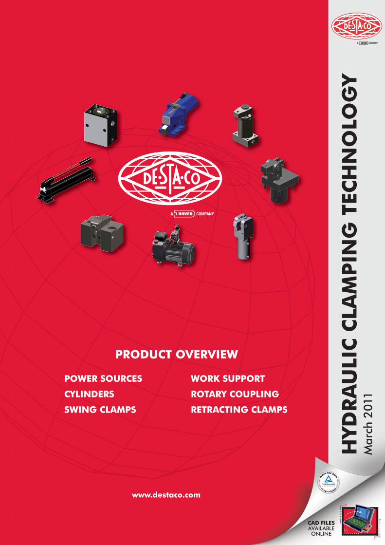
HYD
RA
ULI
C C
LAM
PIN
G T
ECH
NO
LOG
YM
arch
201
1
www.destaco.com
PRODUCT OVERVIEW
POWER SOURCES WORK SUPPORT
CYLINDERS ROTARY COUPLING
SWING CLAMPS RETRACTING CLAMPS
CAD FILESAVAILABLEONLINE
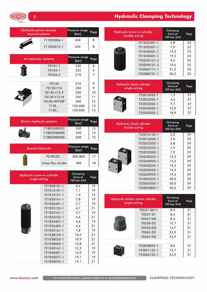
Hydraulic block cylinderdouble acting
Clampingforce at
100 bar [kN]Page
722D16162-1 2,0 29722D16502-1 2,0 29722D25202-1 4,8 29722D32252-1 7,9 29722D32502-1 7,9 29722D40252-1 12,3 29722D40992-1 12,3 29722D50252-1 19,3 29722D50502-1 19,3 29722D50992-1 19,3 29722D63252-1 30,0 29722D63502-1 30,0 29722D63802-1 30,0 29
Hydraulic Clamping Technology2
Hydraulic screw-in cylinderdouble acting
Clampingforce at
100 bar [kN]Page
721D25501-1 4,8 23721D32501-1 7,9 23721D40501-1 12,3 23721D50501-1 19,3 23725D35151-2 9,6 25725D50151-2 19,6 25725D63171-1 31,2 25725D80151-1 50,3 25
Hydraulic block cylindersingle acting
Clampingforce at
100 bar [kN]Page
722E16202-1 1,9 27722E25202-1 4,6 27722E32202-1 7,7 27722E40202-1 12,0 27722E50202-1 18,9 27
Hydraulic hollow piston cylindersingle acting
Clampingforce at
100 bar [kN]Page
70537-DX11 8,0 3170537-D1 8,4 3170537-DG 8,4 3170550-D2 15,7 3170550-DG 15,7 3170562-D2 23,9 3170562-DG 23,9 31
723E38092-1 8,0 31723E51122-1 15,7 31723E63152-1 23,9 31
Hydraulic power sourcesmanual systems
Pressure range[bar]
Page
711E35004-1 350 8
711E35012-1 350 8
Air-hydraulic systemsPressure range
[bar]Page
70101-1 230 670104-1 225 670104-2 210 7
70130 210 970130-Y12 350 9
70130-Y12-F 350 1070130-Y12-H 350 1170130-HW1DP 360 12
713E… 150-600 13713D… 150-600 13
Electro-hydraulic systemsPressure range
[bar] Page
718D3500201 350 15718D3500402 350 15718D2000402 200 15
Special hydraulicPressure range
[bar] Page
70-HC2D… 380-800 17
Linear flow divider 300 18
Hydraulic screw-in cylinder single acting
Clampingforce at
100 bar [kN]Page
721E08101-1 0,4 19721E12101-1 1,1 19721E16121-1 1,9 19721E20161-1 2,8 19721E20401-1 2,7 19721E25155-1 4,7 21721E25161-1 4,7 19721E25255-1 4,6 21721E25401-1 4,6 19721E25405-1 4,6 21721E32161-1 7,8 19721E38125-1 10,9 21721E38255-1 10,9 21721E38505-1 10,8 21721E40161-1 12,2 19721E40401-1 12,0 19721E50251-1 19,1 19721E50255-1 19,1 21
For more information, please contact us at [email protected] CLAMPING TECHNOLOGY
Hydraulic Clamping Technology 3
Hydraulic swing clampsdouble acting
Clampingforce at
100 bar [kN]Page
726D25221-2 1,9 35726D32321-2 3,4 35726D40341-2 5 35
726D25222-2 1,9 35726D32322-2 3,4 35726D40342-2 5 35
726D32243-2 3,2 35726D32373-2 3,2 35726D50293-2 6,4 35726D50393-2 6,4 35
726D32244-2 3,2 35726D32374-2 3,2 35726D50294-2 6,4 35726D50394-2 6,4 35
726D25082-5 1,6 35726D32122-5 3,2 35726D50162-5 6,4 35726D63242-5 9,6 35
726D25083-5 1,6 35726D32123-5 3,2 35726D50163-5 6,4 35726D63243-5 9,6 35
726D25084-5 1,6 35726D32124-5 3,2 35726D50164-5 6,4 35726D63244-5 9,6 35
Hydraulic work supportsLockingforce at
100 bar [kN]Page
724E160811-1 2,5 52
724E160812-1 2,5 52
724E201232-1 2,8 53724E301232-1 4,7 53724E401632-1 7,0 53
724E201242-1 2,8 54724E301242-1 4,7 54724E401642-1 7,0 54
Rotary coupling Page
70-DR20-1 5670-DR20-2 5670-DR40-1 5670-DR40-2 5670-DR60-1 5670-DR60-2 56
Hydraulic hollow piston cylinderdouble acting
Clampingforce at
100 bar [kN]Page
7411-2 8,6 337412-2 12,9 337413-2 18,1 337414-2 26,2 33
723D38102-2 8,6 33723D48152-2 12,9 33723D57242-2 18,1 33723D68242-2 26,2 33
Hydraulic lever clampdouble acting
Clampingforce at
100 bar [kN]Page
732D16HSZY-01 1,5 47732D25HSZY-01 3,9 47732D40HSZY-01 9,5 47
Hydraulic retracting clampdouble acting
Clampingforce at
100 bar [kN]Page
70622-D1 6,5 49
70622-DA 6,5 49
Hydraulic power clampsingle-/double acting
Clampingforce at
100 bar [kN]Page
7011-5 5,0 50
7012-2 5,0 50
Hydraulic edge clampsingle acting
Clampingforce at
100 bar [kN]Page
733E03701-1 3,7 51
733E03702-1 3,7 51
For more information, please contact us at [email protected] www.destaco.comCLAMPING TECHNOLOGY
General information
For more information, please contact us at [email protected]
4
www.destaco.com CLAMPING TECHNOLOGY
General informationClamping of workpieces for machining purposes has a majoreffect on the product quality, the manufacturing times, thedegree of machine utilisation, the operator’s safety and onthe production plant. The emphasis is on secure clampingand rapid changing of the workpieces.The clamping forces must be high enough to clamp theworkpieces safely even when being exposed to varying loads.
Requirements of modern clamping equipment:• Simple, rapid and safe handling• Wide variety of applications, re-usable• Easily exchangeable• Low costs per clamping point• High output per time unit• High quality of the machined workpieces
The profitability and rationalisation effect essentially dependon the choice of the correct clamping equipment. The electri-cal and air hydraulic power clamping system of DE-STA-COmeets these requirements and helps to solve the variousproblems of clamping.
The systemThe power sources, clamping elements and accessoriesshown in this catalogue are products which meet all the de-mands of modern clamping systems. The clamping systemcan be connected to any pneumatic, hydraulic and electricalnetwork. If none of the energy sources is available, the re-quired clamping pressure can be produced by a hydraulichand pump (e.g. in smaller workshops and building sites).The benefits and effects of the system remain the same, re-gardless of the choice of the energy source. The clampingsystem operates with high pressure hydraulics; it allows totransfer high clamping forces by the use of relatively smallclamping elements. This offers the advantage to use small,mobile devices. A particular advantage of this electrical andair hydraulic power clamping system is its application both inlarge high capacity production plants and small series pro-duction. Furthermore, it is used in fixed cycle operation onmachine tools.The clamping elements simultaneously clamp on various andremote clamping points with only one control valve. Theclamping system’s flexibility and its wide range of accessoriesallow to clamp even complex and irregularly shaped parts.The clamping pressures can be repeated as often as neces-sary. All system elements are supplied ex works along withinternational standard pipe thread connectors or NPT-threadconnectors. Adaptors (supplied free of charge along with theunit) allow to connect the NPT-threads to different types ofthreads or screw connections.
Assembly and ConnectionAlignment, assembly and connection can be carried out easilyand quickly without special tools. The power sources, such aspressure convertors, air hydraulic pumps or electrical hydraulicpumps, are first connected to the pneumatic or electrical net-works. Thereafter, they are connected to the clamping units. It is also possible to directly connect the clamping units to analready existing hydraulic network. However, the pressure produced by the hydraulic network must never exceed themaximum operating pressure of the clamping units. Before actuating the clamping system, it must be ventilated at itshighest point.This procedure is explained in detail in the assembly instructions delivered along with the power sources.
Information on sealsAll seals are made of BUNA N. This material is suitable forgas, air, hydraulic oil and mineral oil based liquids (water-glycol-mixtures). The material BUNA N is not suitable forhardly combustible hydraulic liquids, brake fluids, cetones and acids. Also cooling fluids are not always compatible withstandard seals and may affect compatibillity characteristics ofsealing material.BUNA N seals are designed for maximum operating tempera-tures of 110 °C. For operating temperatures exceeding 110 °C,VITON seals having a maximum operating temperature of210 °C must be used.The seals are designded for a maximum stroke speed of V max. = 0,5 m/sec.
Approved oilHydraulic oil: HLP according to the DIN 51524 Part 2
Viscosity range:min. 22 mm2/s, max. 68 mm2/s
Recommended viscosity grade:ISO VG 32 or VG 46 DIN 51519
Operating temperature:40 °C–50 °C
Filtering:use only filtered hydraulic oil of 25 µm absolute.
General information 5
For more information, please contact us at [email protected] www.destaco.comCLAMPING TECHNOLOGY
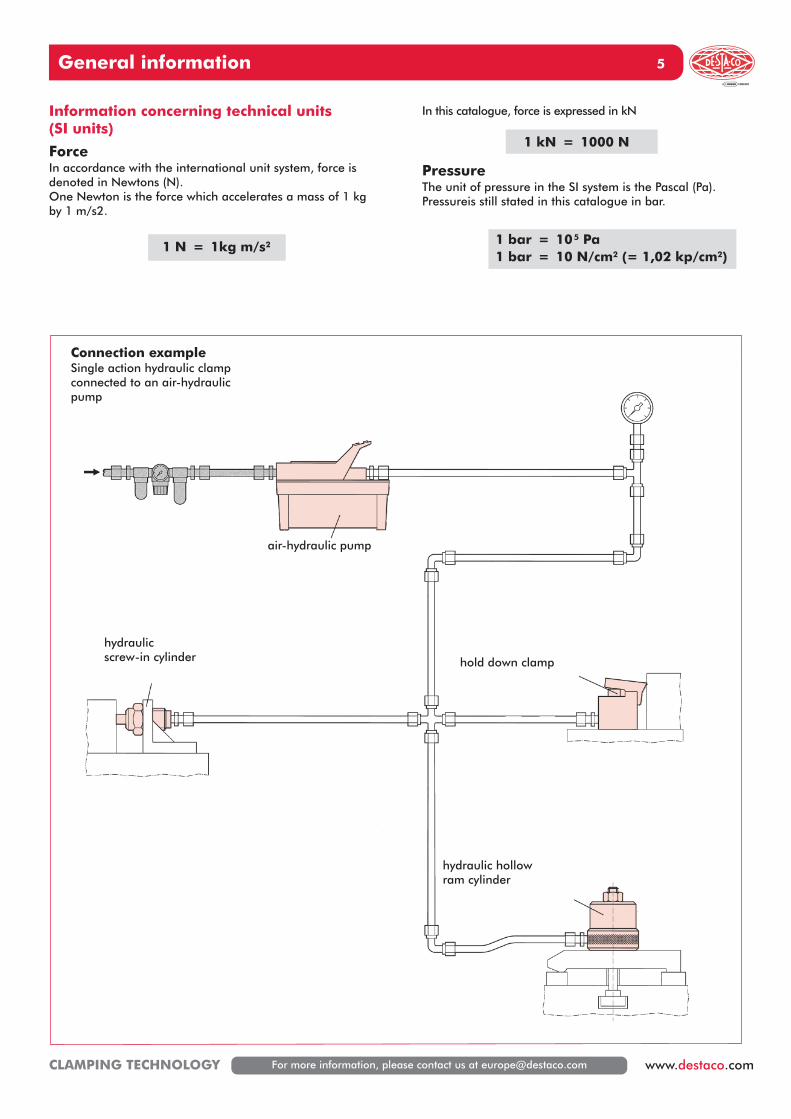
Information concerning technical units (SI units)
ForceIn accordance with the international unit system, force is denoted in Newtons (N).One Newton is the force which accelerates a mass of 1 kg by 1 m/s2.
1 N = 1kg m/s2
In this catalogue, force is expressed in kN
1 kN = 1000 N
PressureThe unit of pressure in the SI system is the Pascal (Pa). Pressureis still stated in this catalogue in bar.
1 bar = 105 Pa1 bar = 10 N/cm2 (= 1,02 kp/cm2)
Connection exampleSingle action hydraulic clampconnected to an air-hydraulicpump
air-hydraulic pump
hydraulicscrew-in cylinder hold down clamp
hydraulic hollowram cylinder
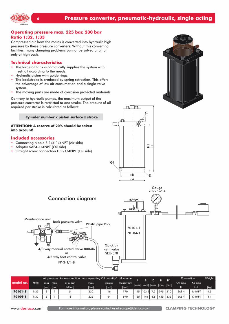
Pressure converter, pneumatic-hydraulic, single acting6
For more information, please contact us at [email protected] CLAMPING TECHNOLOGY
Operating pressure max. 225 bar, 230 barRatio 1:32, 1:33Compressed air from the mains is converted into hydraulic highpressure by these pressure converters. Without this convertingfacilities, many clamping problems cannot be solved at all oronly at high costs.
Technical characteristics• The large oil tank automatically supplies the system with
fresh oil according to the needs.• Hydraulic piston with guide rings.• The backstroke is produced by spring retraction. This offers
the advantage of low air consumption and a single valve system.
• The moving parts are made of corrosion protected materials.
Contrary to hydraulic pumps, the maximum output of the pressure converter is restricted to one stroke. The amount of oilrequired per stroke is calculated as follows:
Cylinder number x piston surface x stroke
ATTENTION: A reserve of 20% should be taken into account!
Included accessories• Connecting nipple R-1/4-1/4NPT (Air side)• Adapter SAE4-1/4NPT (Oil side)• Straight screw connection D8L-1/4NPT (Oil side)
Maintenance unit
4/3 way manual control valve 800416or
3/2 way foot control valve
Quick airvent valveSEU-3/8
Plastic pipe PL-9Back pressure valve
70101-1
70104-1
Gauge70925-214
Connection diagram
FP-3-1/4-B
AB
H1
H
G
G1
D
model no. Ratio
Air pressure Air consumption max. operating Oil quantity/ oil volumeA
[mm]
B
[mm]
D
[mm]
H
[mm]
H1
[mm]
Connection Weight
min max. at 6 bar max. stroke (Reservoir) Oil side Air side
[bar] [bar] [l/Hub] [bar] [cm³] [cm³] G G1 [kg]
70101-1 1:33 3 7 5 230 16 170 115 103,2 7,2 295 210 SAE 4 1/4NPT 4.5
70104-1 1:32 3 7 16 225 64 690 165 146 8,6 435 335 SAE 4 1/4NPT 11
Pressure converter, pneumatic-hydraulic, single acting 7
For more information, please contact us at [email protected] www.destaco.comCLAMPING TECHNOLOGY
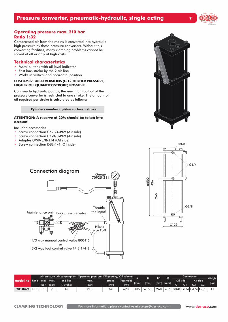
Operating pressure max. 210 barRatio 1:32Compressed air from the mains is converted into hydraulichigh pressure by these pressure converters. Without this converting facilities, many clamping problems cannot besolved at all or only at high costs.
Technical characteristics• Metal oil tank with oil level indicator• Fast backstroke by the 2.air line• Works in vertical and horizontal position
CUSTOMER BUILD VERSIONS (E. G. HIGHER PRESSURE,HIGHER OIL QUANTITY/STROKE) POSSIBLE.
Contrary to hydraulic pumps, the maximum output of the pressure converter is restricted to one stroke. The amount ofoil required per stroke is calculated as follows:
Cylinders number x piston surface x stroke
ATTENTION: A reserve of 20% should be taken into account!
Included accessories• Screw connection CK-1/4-PK9 (Air side)• Screw connection CK-3/8-PK9 (Air side)• Adapter GWR-3/8-1/4 (Oil side)• Screw connection D8L-1/4 (Oil side)
bar
31 2
4
Gauge70925-214
4/3 way manual control valve 800416or
3/2 way foot control valve FP-3-1/4-B
Maintenance unit
Plasticpipe PL-9
Back pressure valve
Throttlethe input!
Connection diagram
135
26
04
36
ca.5
00
G3/8
G3/8
G1/4
model no. Ratio
Air pressure Air consumption Operating pressure Oil quantity/ Oil volumeA
[mm]
H
[mm]
H1
[mm]
H2
[mm]
ConnectionWeight
[kg]min max. at 6 bar max. stroke (reservoir) Oil side Air side
[bar] [bar] [l/stroke] [bar] [cm³] [cm³] G G1 G2 G3
70104-2 1:30 3 7 16 210 64 690 135 ca. 500 260 436 G3/8 G1/4 G1/4 G3/8 11
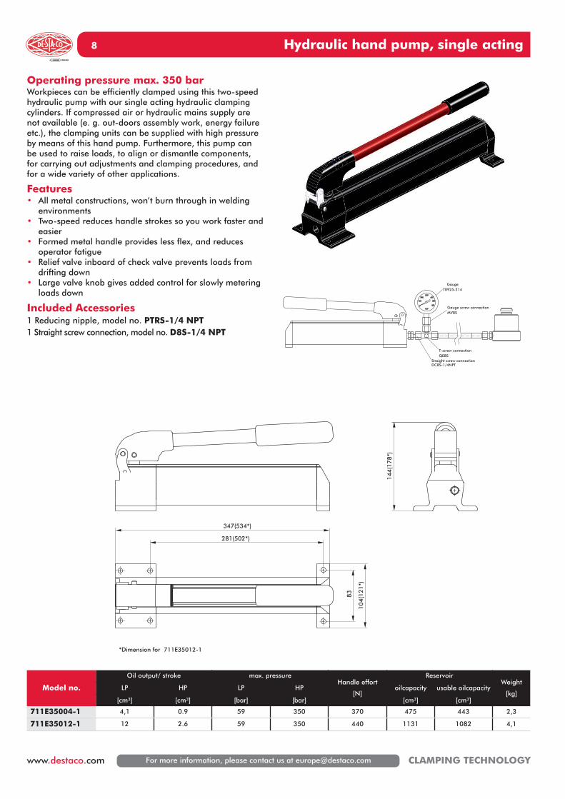
Hydraulic hand pump, single acting8
For more information, please contact us at [email protected] CLAMPING TECHNOLOGY
Gauge70925-214
Gauge screw connectionMV8S
T-screw connectionQE8S
Straight screw connectionDC8S-1/4NPT
83
104
(121*)
*Dimension for 711E35012-1
347(534*)
144
(178*)
281(502*)
Operating pressure max. 350 barWorkpieces can be efficiently clamped using this two-speedhydraulic pump with our single acting hydraulic clampingcylinders. If compressed air or hydraulic mains supply arenot available (e. g. out-doors assembly work, energy failureetc.), the clamping units can be supplied with high pressureby means of this hand pump. Furthermore, this pump canbe used to raise loads, to align or dismantle components,for carrying out adjustments and clamping procedures, andfor a wide variety of other applications.
Features• All metal constructions, won’t burn through in welding
environments• Two-speed reduces handle strokes so you work faster and
easier• Formed metal handle provides less flex, and reduces
operator fatigue• Relief valve inboard of check valve prevents loads from
drifting down• Large valve knob gives added control for slowly metering
loads down
Included Accessories1 Reducing nipple, model no. PTRS-1/4 NPT1 Straight screw connection, model no. D8S-1/4 NPT
Model no.
Oil output/ stroke max. pressureHandle effort
[N]
ReservoirWeight
[kg]LP HP LP HP oilcapacity usable oilcapacity
[cm³] [cm³] [bar] [bar] [cm³] [cm³]
711E35004-1 4,1 0.9 59 350 370 475 443 2,3
711E35012-1 12 2.6 59 350 440 1131 1082 4,1
Air hydraulic pump 9
For more information, please contact us at [email protected] www.destaco.comCLAMPING TECHNOLOGY
1800
1500
1200
900
600
300
00 100 200 300 400 500 600 700
operating pressure [bar]
70130
outp
ut [
cm3/m
in]
Output characteristics
air pressure at 7 bar
70130-Y12 70130-Y12-F
70130-Y12 70130-Y12-F
operating pressure setat max. 350 bar
197
254144
releaseclamp
127
Oil connector3/8NPT
filler plugAir connector
1/4NPT
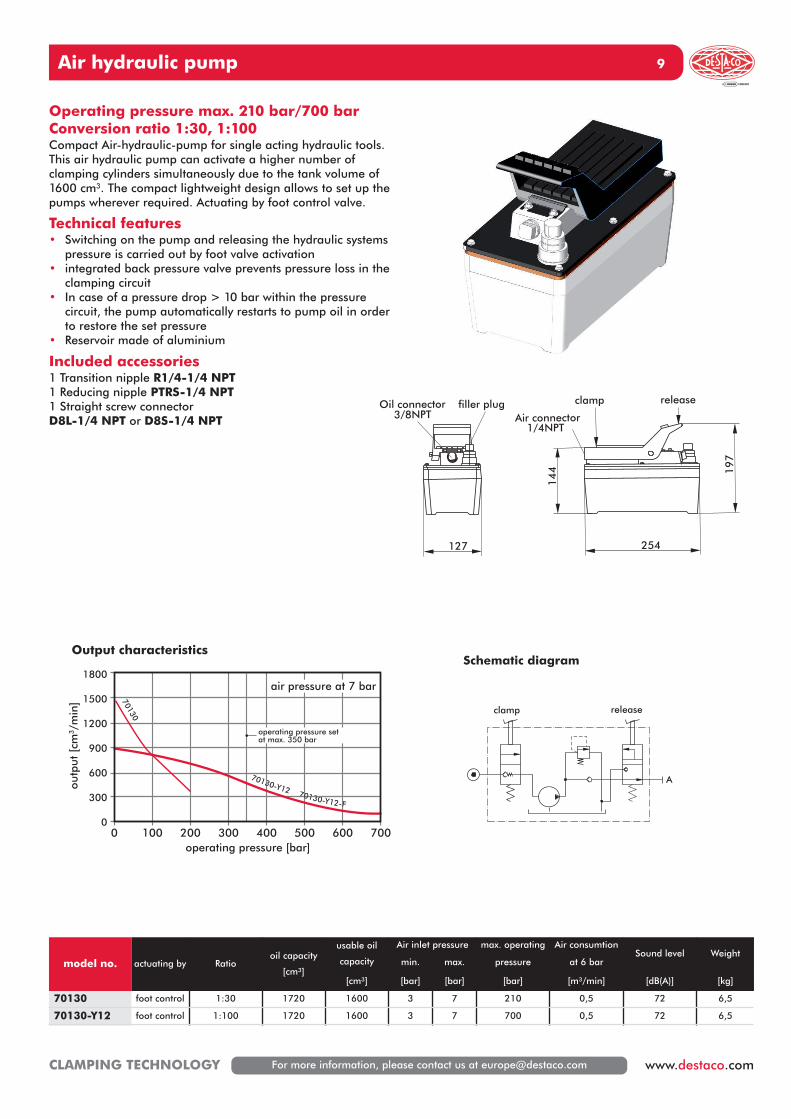
Operating pressure max. 210 bar/700 barConversion ratio 1:30, 1:100Compact Air-hydraulic-pump for single acting hydraulic tools.This air hydraulic pump can activate a higher number ofclamping cylinders simultaneously due to the tank volume of1600 cm3. The compact lightweight design allows to set up thepumps wherever required. Actuating by foot control valve.
Technical features• Switching on the pump and releasing the hydraulic systems
pressure is carried out by foot valve activation• integrated back pressure valve prevents pressure loss in the
clamping circuit• In case of a pressure drop > 10 bar within the pressure
circuit, the pump automatically restarts to pump oil in orderto restore the set pressure
• Reservoir made of aluminium
Included accessories1 Transition nipple R1/4-1/4 NPT1 Reducing nipple PTRS-1/4 NPT1 Straight screw connectorD8L-1/4 NPT or D8S-1/4 NPT
model no. actuating by Ratiooil capacity
[cm³]
usable oil
capacity
Air inlet pressure max. operating Air consumtionSound level Weight
min. max. pressure at 6 bar
[cm³] [bar] [bar] [bar] [m³/min] [dB(A)] [kg]
70130 foot control 1:30 1720 1600 3 7 210 0,5 72 6,5
70130-Y12 foot control 1:100 1720 1600 3 7 700 0,5 72 6,5
releaseclamp
A
Schematic diagram
Air hydraulic pump10
For more information, please contact us at [email protected] CLAMPING TECHNOLOGY
model no actuating by Ratio
Reservoir oil
capacity
usable oilcapacity
Air inlet pressure max. operating Air consumption Soundlevel Weight
[kg]min. max. pressure at 6 bar
[cm³] [cm³] [bar] [bar] [bar] [m³/min] [dB(A)]
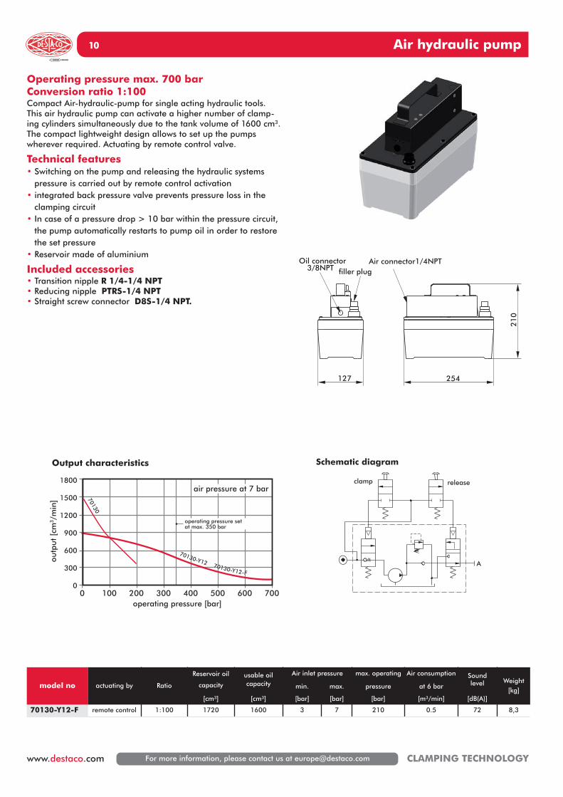
70130-Y12-F remote control 1:100 1720 1600 3 7 210 0.5 72 8,3
Operating pressure max. 700 barConversion ratio 1:100Compact Air-hydraulic-pump for single acting hydraulic tools.This air hydraulic pump can activate a higher number of clamp-ing cylinders simultaneously due to the tank volume of 1600 cm3.The compact lightweight design allows to set up the pumps wherever required. Actuating by remote control valve.
Technical features• Switching on the pump and releasing the hydraulic systems
pressure is carried out by remote control activation• integrated back pressure valve prevents pressure loss in the
clamping circuit• In case of a pressure drop > 10 bar within the pressure circuit,
the pump automatically restarts to pump oil in order to restorethe set pressure
• Reservoir made of aluminium
Included accessories• Transition nipple R 1/4-1/4 NPT• Reducing nipple PTRS-1/4 NPT• Straight screw connector D8S-1/4 NPT.
254
21
0
Air connector1/4NPT
127
Oil connector3/8NPT filler plug
A
clamp release
Schematic diagram
1800
1500
1200
900
600
300
00 100 200 300 400 500 600 700
operating pressure [bar]
70130
outp
ut [
cm3/m
in]
Output characteristics
air pressure at 7 bar
70130-Y12 70130-Y12-F
70130-Y12 70130-Y12-F
operating pressure setat max. 350 bar
Air hydraulic pump 11
For more information, please contact us at [email protected] www.destaco.comCLAMPING TECHNOLOGY
Operating pressure max. 700 barConversion ratio 1:100Compact Air-hydraulic-pump for single– and double acting hy-draulic tools. This air hydraulic pump can activate a higher numberof clamping cylinders simultaneously due to the tank volume of1600 cm3. The compact lightweight design allows to set up thepumps wherever required. Actuating by manual control valve.
Technical features• Switching on the pump and releasing the hydraulic systems pres-
sure is carried out by manual control valve activation• integrated back pressure valve prevents pressure loss in the
clamping circuit• In case of a pressure drop > 10 bar within the pressure circuit,
the pump automatically restarts to pump oil in order to restorethe set pressure
• Reservoir made of aluminium
Included accessories1 transition nipple R 1/4-1/4 NPT2 reducing nipple PTRS-1/4 NPT2 straight screw connector D8S-1/4 NPT.
2552
90
Oil connector3/8NPT
Air connector1/4NPTfilling
plug
127
AB
model no. actuating by Ratiooil capacity
usable oil
capacity
Air inlet pressure max. operating
pressure
Air consumption Sound
levelWeight
min. max. at 6 bar
[cm³] [cm³] [bar] [bar] [bar] [m³/min] [dB(A)] [kg]
70130-Y12-H manual valve 1:100 1720 1600 3 7 700 0,5 72 8,4
Schematic diagram1800
1500
1200
900
600
300
00 100 200 300 400 500 600 700
operating pressure [bar]
outp
ut [
cm3/m
in]
Output characteristics
air pressure at 7 bar
operating pressure setat max. 350 bar
Air hydraulic pump12
For more information, please contact us at [email protected] CLAMPING TECHNOLOGY
Maintenance unitC08-C2-FKG0
T-fittingFCK-3-PK6
plastic pipePK-6
Manual control valve800416
orfoot control valve
FP-3-1/4-B
pneumatic connector CK-1/4-PK6hydraulic connector: D8S-R1/4
158
173212
121
1788
176
203
158
373
Oil connector2xG1/4
Connectorcontrol air
G1/4Air connector
1/4NPT
AB
tank inlet/deaeration
Deaeration
Operating pressure max. 360 barConversion ratio 1:60Compact Air-hydraulic-pump for single– and double act-ing hydraulic tools. This air hydraulic pump can activate ahigher number of clamping cylinders simultaneously dueto the tank volume of 2100 cm3. The compact lightweightdesign allows to set up the pumps wherever required.
Technische Merkmale• Switching on the pump and releasing the hydraulic
systems pressure is carried out by foot valve activation• Valve control via air controlled 4/2 way direction valve• In case of a pressure drop > 10 bar within the pres-
sure circuit, the pump automatically restarts to pumpoil in order to restore the set pressure
Optional:• System extendible via valve vertical interconnection• Electro-magnetic, mechanical or manual controlled
valves available
Y A B
A+B=hydraulic loadY=pneumatic control pipe
3,0
2,5
2,0
1,5
1,0
0,5
00 50 100 150 200 250 300 350
operating pressure [bar]
outp
ut [
l/m
in]
No-load output flowat 6 bar approx. 1,5 l/min.
model no. actuating by Ratiooil quantity
usable oilquantity
Air inlet pressure max. operating Air consumptionat 6 bar
Sound
levelWeight
min. max. pressure
[cm³] [cm³] [bar] [bar] [bar] [m³/min] [dB(A)] [kg]
70130-HW1DP
4/2 way seatvalve, pneu-matic piloting
1:60 2500 2100 3 6 360 0,5 79 6,4
Schematic diagramConnection diagram
Output characteristics
Air hydraulic pump 13
For more information, please contact us at [email protected] www.destaco.comCLAMPING TECHNOLOGY
400 1000
713D/E3605.-1
900
800
700
600
500
400
300
200
100
0
0,0
0,4
0,8
4,8
4,4
4,0
3,6
3,2
2,8
2,4
2,0
1,6
1,2
350
300
250
200
150
100
50
0
4 bar 4 bar
6 bar 6 bar700 1000
713D/E6005.-1
900
800
700
600
500
400
300
200
100
0
0,0
0,2
0,4
2,4
2,2
2,0
1,8
1,6
1,4
1,2
1,0
0,8
0,6
600
500
400
300
200
100
0
4 bar4 bar
6 bar6 bar
200 1000
713D/E1505.-1
900
800
700
600
500
400
300
200
100
Output (l/min)
Ope
ratin
g pr
essu
re
(bar
)
Air
con
sum
ptio
n (l/
min
)
00 1 2 1211109876543
160
180
140
120
100
80
40
60
20
0
4 bar
4 bar
6 bar
6 bar
Output (l/min)
Ope
ratin
g pr
essu
re (b
ar)
Air
con
sum
ptio
n (l/
min
)
Output (l/min)
Ope
ratin
g pr
essu
re (b
ar)
Air
con
sum
ptio
n (l/
min
)
Operating pressure max. 150 bar/360 bar/600 barConversion ratio 1:25/1:60/1:1000These air hydraulic pumps are designed for various hydraulic applications,especially for intermittent operation. By connecting a 3/2- way or 4/2-waypneumatic valve, the built-in hydraulic valves for stroke and backstrokecan be actuated. The pumps are complete, and only have to be connectedto the existing compressed air supply.
Technical characteristics• Double piston pump-therefore pressure build-up almost pulsation free• Compact pump - low required space• 3 different conversion ratios available• integrated back pressure valve prevents pressure loss in the clamping
circuit• In case of a pressure drop > 10 bar within the pressure circuit, the
pump automatically restarts to pump oil in order to restore the setpressure
Recommended accessories (separate order)1 4/2-ways manual-control-valve 800416 1 3/2-way-foot-control-valve FP-3-1/4-H2 screw-in connections CK-1/4-PK61 screw-in connections CK-3/8-PK9
model no.Ratio
max. operating Reservoir usable oil
quantity
Air inlet pressureConnection
oil side
SoundWeight
pressure oil quantity min. max level
single acting double acting [bar] [l] [l] [bar] [bar] [dB(A)] [kg)]
713E15051-1 1:25 150 8 5,5 1,5 6 1xG1/4 65 30
713D15051-1 1:25 150 8 5,5 1,5 6 2xG1/4 65 31
713E36051-1 1:60 360 8 5,5 1,5 6 1xG1/4 65 30
713D36051-1 1:60 360 8 5,5 1,5 6 2xG1/4 65 31
713E60051-1 1:100 600 8 5,5 1,5 6 1xG1/4 65 30
713D60051-1 1:100 600 8 5,5 1,5 6 2xG1/4 65 31
14 Air hydraulic pump
For more information, please contact us at [email protected] CLAMPING TECHNOLOGY
Maintenance unitC08-C2-FKG0
Manual control valve 800416or
foot control valve FP-3-1/4-B
double acting
single acting
A B
Connection diagram:in this connection diagram you can see an air hydraulic pump, double action, with pneumatic control. On a single action design, the connection B does not apply.
P1P YA P1P Y A B
Clamping circuit combinations
1 clamping circuit*, single action*713E15051-1, 713E36051-1, 713E60051-1
1 clamping circuit*, double action*713D15051-1, 713D36051-1, 713D60051-1
* Pumps with more circuits, with electrically controlled valves, positioning circuit or accumulator control unit circuit are also available.500
310
G1/4
242
G1/4 G3/8
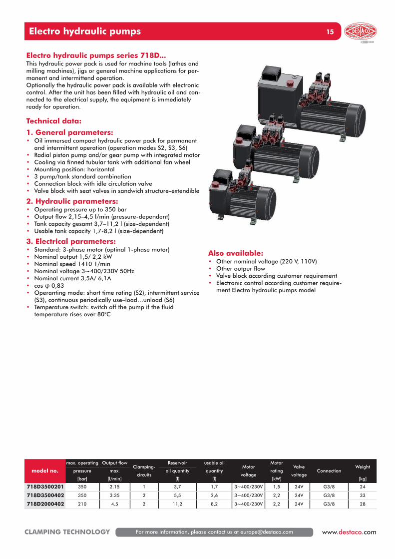
15Electro hydraulic pumps
For more information, please contact us at [email protected] www.destaco.comCLAMPING TECHNOLOGY
Also available:• Other nominal voltage (220 V, 110V)• Other outpur flow• Valve block according customer requirement• Electronic control according customer require-
ment Electro hydraulic pumps model
Electro hydraulic pumps series 718D...This hydraulic power pack is used for machine tools (lathes andmilling machines), jigs or general machine applications for per-manent and intermittend operation.Optionally the hydraulic power pack is available with electroniccontrol. After the unit has been filled with hydraulic oil and con-nected to the electrical supply, the equipment is immediatelyready for operation.
Technical data:
1. General parameters:• Oil immersed compact hydraulic power pack for permanent
and intermittent operation (operation modes S2, S3, S6)• Radial piston pump and/or gear pump with integrated motor• Cooling via finned tubular tank with additional fan wheel• Mounting position: horizontal• 3 pump/tank standard combination• Connection block with idle circulation valve• Valve block with seat valves in sandwich structure-extendible
2. Hydraulic parameters:• Operating pressure up to 350 bar• Output flow 2,15–4,5 l/min (pressure-dependent)• Tank capacity gesamt 3,7–11,2 l (size-dependent)• Usable tank capacity 1,7-8,2 l (size-dependent)
3. Electrical parameters:• Standard: 3-phase motor (optinal 1-phase motor)• Nominal output 1,5/ 2,2 kW• Nominal speed 1410 1/min• Nominal voltage 3~400/230V 50Hz• Nominal current 3,5A/ 6,1A• cos φ 0,83• Operanting mode: short time rating (S2), intermittent service
(S3), continuous periodically use–load…unload (S6)• Temperature switch: switch off the pump if the fluid
temperature rises over 80°C
model no.
max. operating Output flowClamping-
circuits
Reservoir usable oil
quantityMotor
voltage
Motor
ratingValve
voltageConnection
Weightpressure max. oil quantity
[bar] [l/min] [l] [l] [kW] [kg]
718D3500201 350 2.15 1 3,7 1,7 3~400/230V 1,5 24V G3/8 24
718D3500402 350 3.35 2 5,5 2,6 3~400/230V 2,2 24V G3/8 33
718D2000402 210 4.5 2 11,2 8,2 3~400/230V 2,2 24V G3/8 28
Electro hydraulic pump16
For more information, please contact us at [email protected] CLAMPING TECHNOLOGY
Y1
Y2 Y3
210bar
4,5
l/min
Y1
Y2
350bar
2,15 l/min
Y1
Y2 Y3
350bar
3,35
l/min
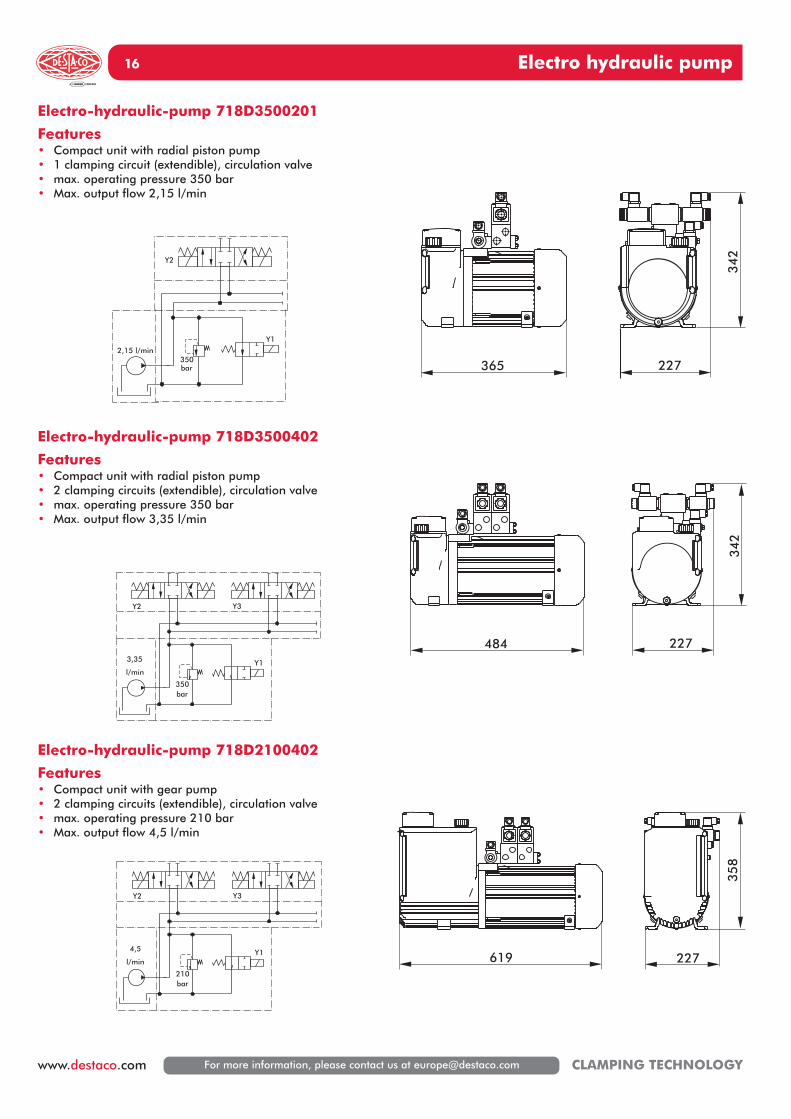
Electro-hydraulic-pump 718D3500201
Features• Compact unit with radial piston pump• 1 clamping circuit (extendible), circulation valve• max. operating pressure 350 bar• Max. output flow 2,15 l/min
Electro-hydraulic-pump 718D3500402
Features• Compact unit with radial piston pump• 2 clamping circuits (extendible), circulation valve• max. operating pressure 350 bar• Max. output flow 3,35 l/min
Electro-hydraulic-pump 718D2100402
Features• Compact unit with gear pump• 2 clamping circuits (extendible), circulation valve• max. operating pressure 210 bar• Max. output flow 4,5 l/min
484 227
342
365
342
227
619 227
35
8
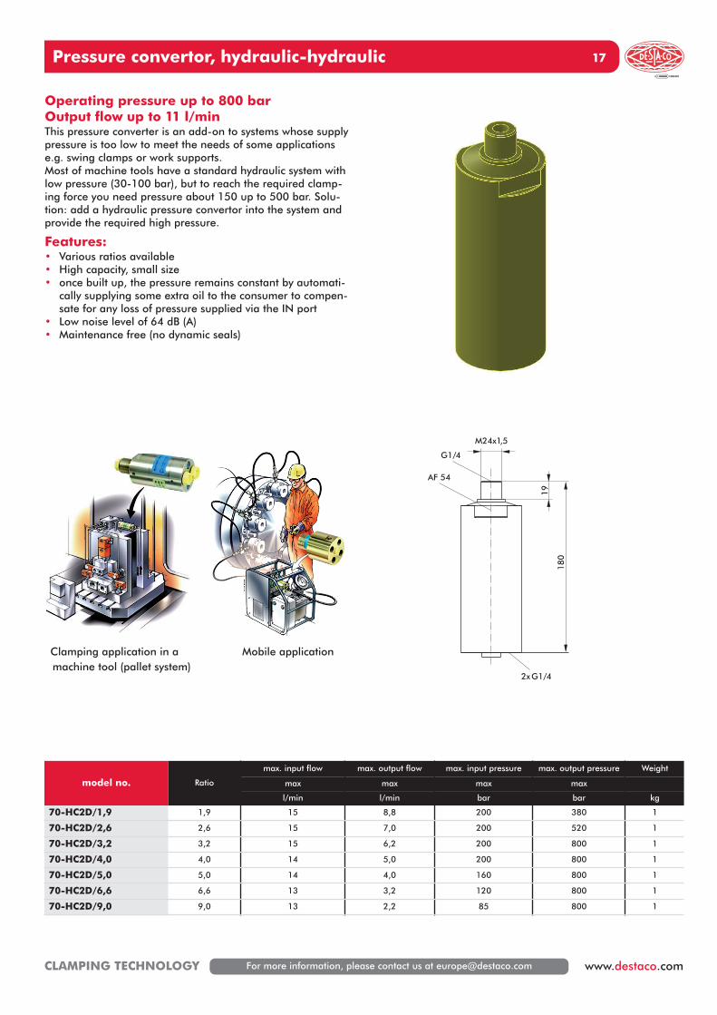
Pressure convertor, hydraulic-hydraulic 17
For more information, please contact us at [email protected] www.destaco.comCLAMPING TECHNOLOGY
Operating pressure up to 800 barOutput flow up to 11 l/minThis pressure converter is an add-on to systems whose supplypressure is too low to meet the needs of some applicationse.g. swing clamps or work supports.Most of machine tools have a standard hydraulic system withlow pressure (30-100 bar), but to reach the required clamp-ing force you need pressure about 150 up to 500 bar. Solu-tion: add a hydraulic pressure convertor into the system andprovide the required high pressure.
Features:• Various ratios available• High capacity, small size• once built up, the pressure remains constant by automati-
cally supplying some extra oil to the consumer to compen-sate for any loss of pressure supplied via the IN port
• Low noise level of 64 dB (A)• Maintenance free (no dynamic seals)
M24x1,5
180
19
AF 54
G1/4
2xG1/4
Clamping application in a machine tool (pallet system)
Mobile application
model no. Ratio
max. input flow max. output flow max. input pressure max. output pressure Weight
max max max max
l/min l/min bar bar kg
70-HC2D/1,9 1,9 15 8,8 200 380 1
70-HC2D/2,6 2,6 15 7,0 200 520 1
70-HC2D/3,2 3,2 15 6,2 200 800 1
70-HC2D/4,0 4,0 14 5,0 200 800 1
70-HC2D/5,0 5,0 14 4,0 160 800 1
70-HC2D/6,6 6,6 13 3,2 120 800 1
70-HC2D/9,0 9,0 13 2,2 85 800 1
18 Hydraulic Synchronous Flow Divider
For more information, please contact us at [email protected] CLAMPING TECHNOLOGY
M
Scope of delivery flow divider
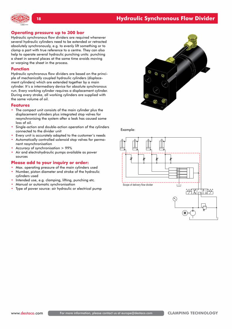
Operating pressure up to 300 barHydraulic synchronous flow dividers are required wheneverseveral hydraulic cylinders need to be extended or retractedabsolutely synchronously, e.g. to evenly lift something or toclamp a part with true reference to a centre. They can alsohelp to operate several hydraulic punching units: punching a sheet in several places at the same time avoids moving or warping the sheet in the process.
FunctionHydraulic synchronous flow dividers are based on the princi-ple of mechanically coupled hydraulic cylinders (displace-ment cylinders) which are extended together by a maincylinder. It‘s a intermediary device for absolute synchronousrun. Every working cylinder requires a displacement cylinder. During every stroke, all working cylinders are supplied withthe same volume of oil.
Features• The compact unit consists of the main cylinder plus the
displacement cylinders plus integrated stop valves for resynchronising the system after a leak has caused someloss of oil.
• Single-action and double-action operation of the cylindersconnected to the divider unit
• Every unit is accurately adapted to the customer’s needs• Automatically controlled solenoid stop valves for perma-
nent resynchronisation• Accuracy of synchronisation > 99%• Air and electrohydraulic pumps available as power
sources
Please add to your inquiry or order:• Max. operating pressure of the main cylinders used• Number, piston diameter and stroke of the hydraulic
cylinders used• Intended use, e.g. clamping, lifting, punching etc.• Manual or automatic synchronisation• Type of power source: air hydraulic or electrical pump
Example:
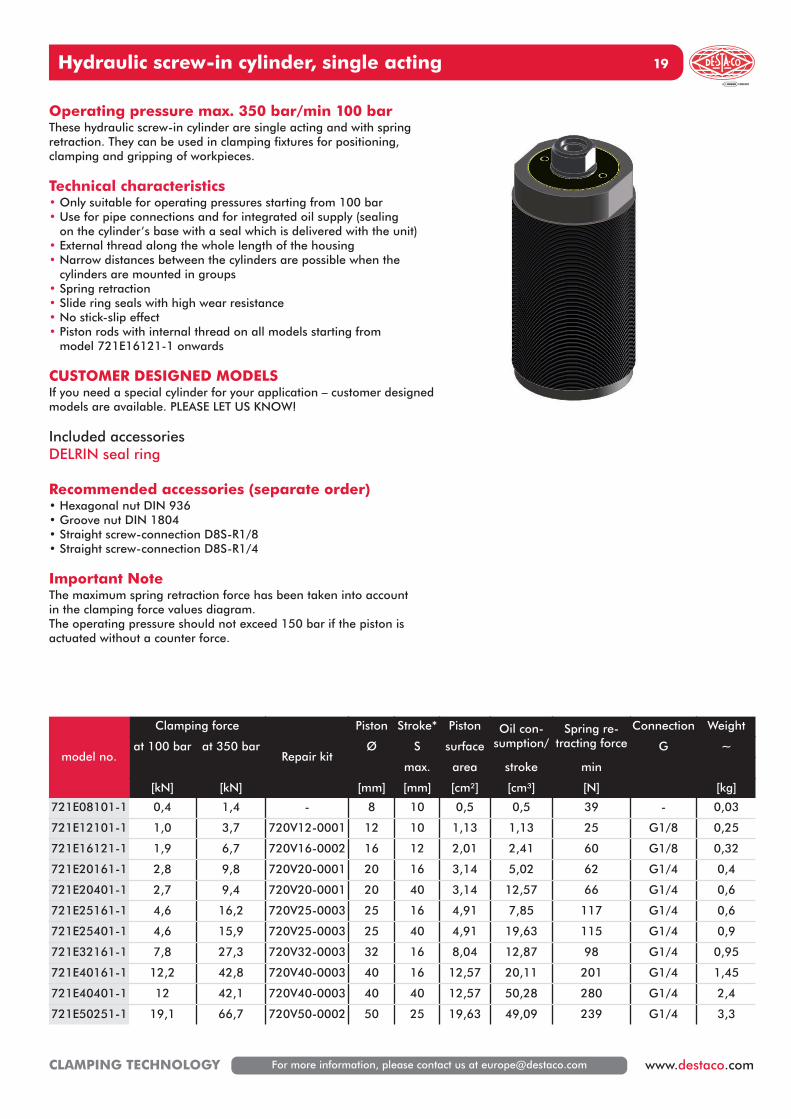
19Hydraulic screw-in cylinder, single acting
For more information, please contact us at [email protected] www.destaco.comCLAMPING TECHNOLOGY
Operating pressure max. 350 bar/min 100 barThese hydraulic screw-in cylinder are single acting and with springretraction. They can be used in clamping fixtures for positioning,clamping and gripping of workpieces.
Technical characteristics• Only suitable for operating pressures starting from 100 bar• Use for pipe connections and for integrated oil supply (sealing
on the cylinder’s base with a seal which is delivered with the unit)• External thread along the whole length of the housing• Narrow distances between the cylinders are possible when the
cylinders are mounted in groups• Spring retraction• Slide ring seals with high wear resistance• No stick-slip effect• Piston rods with internal thread on all models starting from
model 721E16121-1 onwards
CUSTOMER DESIGNED MODELSIf you need a special cylinder for your application – customer designedmodels are available. PLEASE LET US KNOW!
Included accessoriesDELRIN seal ring
Recommended accessories (separate order)• Hexagonal nut DIN 936• Groove nut DIN 1804• Straight screw-connection D8S-R1/8• Straight screw-connection D8S-R1/4
Important NoteThe maximum spring retraction force has been taken into accountin the clamping force values diagram.The operating pressure should not exceed 150 bar if the piston isactuated without a counter force.
model no.
Clamping force
Repair kit
Piston Stroke* Piston Oil con-sumption/
Spring re-tracting force
Connection Weight
at 100 bar at 350 bar Ø S surface G ~
max. area stroke min
[kN] [kN] [mm] [mm] [cm²] [cm³] [N] [kg]
721E08101-1 0,4 1,4 - 8 10 0,5 0,5 39 - 0,03
721E12101-1 1,0 3,7 720V12-0001 12 10 1,13 1,13 25 G1/8 0,25
721E16121-1 1,9 6,7 720V16-0002 16 12 2,01 2,41 60 G1/8 0,32
721E20161-1 2,8 9,8 720V20-0001 20 16 3,14 5,02 62 G1/4 0,4
721E20401-1 2,7 9,4 720V20-0001 20 40 3,14 12,57 66 G1/4 0,6
721E25161-1 4,6 16,2 720V25-0003 25 16 4,91 7,85 117 G1/4 0,6
721E25401-1 4,6 15,9 720V25-0003 25 40 4,91 19,63 115 G1/4 0,9
721E32161-1 7,8 27,3 720V32-0003 32 16 8,04 12,87 98 G1/4 0,95
721E40161-1 12,2 42,8 720V40-0003 40 16 12,57 20,11 201 G1/4 1,45
721E40401-1 12 42,1 720V40-0003 40 40 12,57 50,28 280 G1/4 2,4
721E50251-1 19,1 66,7 720V50-0002 50 25 19,63 49,09 239 G1/4 3,3
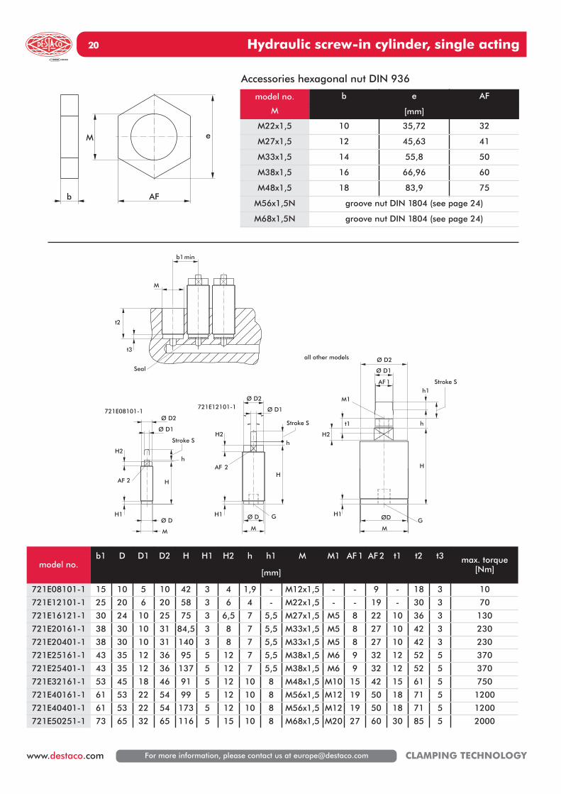
20 Hydraulic screw-in cylinder, single acting
For more information, please contact us at [email protected] CLAMPING TECHNOLOGY
GØ D
M
H2
H1
H
h
Ø D1
Ø D2
AF 2
721E12101-1
Ø D
M
H
h
H1
H2
Ø D1
Ø D2
AF 2
721E08101-1
GØD
M
H
h
Stroke S
H1
H2
t1
M1
AF 1
Ø D1
Ø D2
h1
all other models
b1min
t3
t2
M
Seal
Stroke S
Stroke S
model no.
M
b e AF
[mm]
M22x1,5 10 35,72 32
M27x1,5 12 45,63 41
M33x1,5 14 55,8 50
M38x1,5 16 66,96 60
M48x1,5 18 83,9 75
M56x1,5N groove nut DIN 1804 (see page 24)
M68x1,5N groove nut DIN 1804 (see page 24)
e
AF
M
b
Accessories hexagonal nut DIN 936
model no.b1 D D1 D2 H H1 H2 h h1
[mm]
M M1 AF1 AF2 t1 t2 t3 max. torque[Nm]
721E08101-1 15 10 5 10 42 3 4 1,9 - M12x1,5 - - 9 - 18 3 10
721E12101-1 25 20 6 20 58 3 6 4 - M22x1,5 - - 19 - 30 3 70
721E16121-1 30 24 10 25 75 3 6,5 7 5,5 M27x1,5 M5 8 22 10 36 3 130
721E20161-1 38 30 10 31 84,5 3 8 7 5,5 M33x1,5 M5 8 27 10 42 3 230
721E20401-1 38 30 10 31 140 3 8 7 5,5 M33x1,5 M5 8 27 10 42 3 230
721E25161-1 43 35 12 36 95 5 12 7 5,5 M38x1,5 M6 9 32 12 52 5 370
721E25401-1 43 35 12 36 137 5 12 7 5,5 M38x1,5 M6 9 32 12 52 5 370
721E32161-1 53 45 18 46 91 5 12 10 8 M48x1,5 M10 15 42 15 61 5 750
721E40161-1 61 53 22 54 99 5 12 10 8 M56x1,5 M12 19 50 18 71 5 1200
721E40401-1 61 53 22 54 173 5 12 10 8 M56x1,5 M12 19 50 18 71 5 1200
721E50251-1 73 65 32 65 116 5 15 10 8 M68x1,5 M20 27 60 30 85 5 2000
21Hydraulic screw-in cylinder, single acting
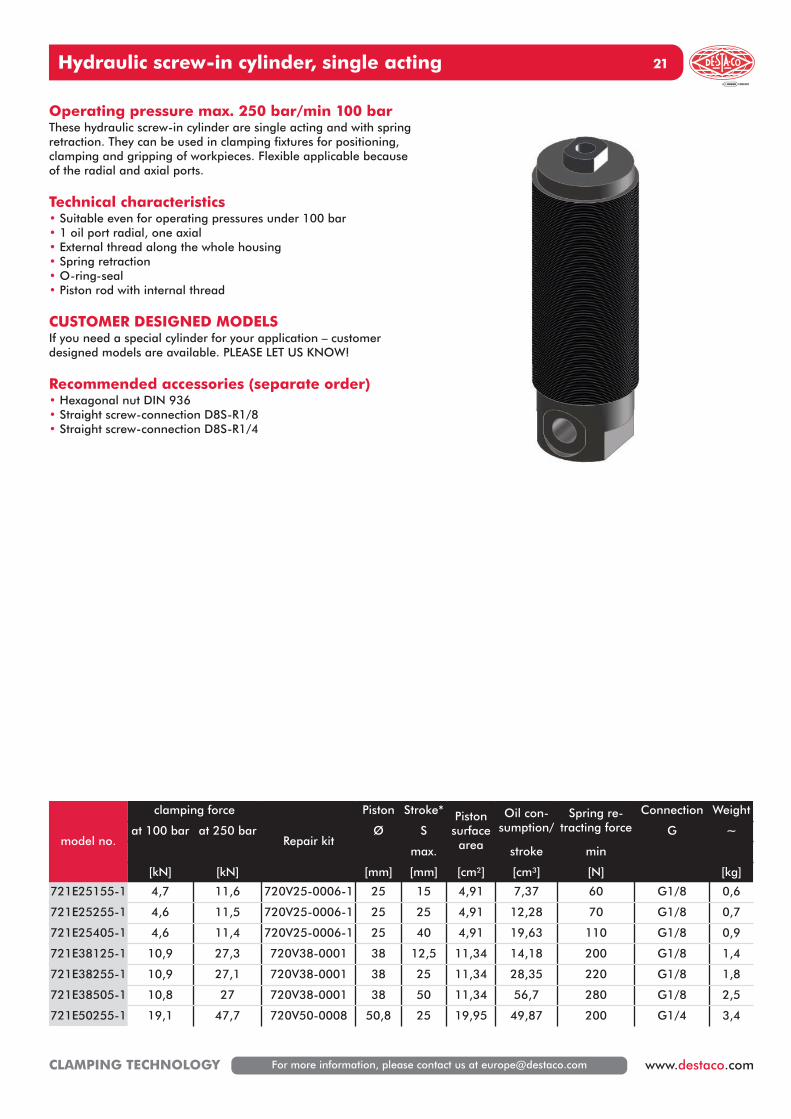
For more information, please contact us at [email protected] www.destaco.comCLAMPING TECHNOLOGY
Operating pressure max. 250 bar/min 100 barThese hydraulic screw-in cylinder are single acting and with springretraction. They can be used in clamping fixtures for positioning,clamping and gripping of workpieces. Flexible applicable becauseof the radial and axial ports.
Technical characteristics• Suitable even for operating pressures under 100 bar• 1 oil port radial, one axial• External thread along the whole housing• Spring retraction• O-ring-seal• Piston rod with internal thread
CUSTOMER DESIGNED MODELSIf you need a special cylinder for your application – customer designed models are available. PLEASE LET US KNOW!
Recommended accessories (separate order)• Hexagonal nut DIN 936• Straight screw-connection D8S-R1/8• Straight screw-connection D8S-R1/4
model no.
clamping force
Repair kit
Piston Stroke* Pistonsurfacearea
Oil con-sumption/
Spring re-tracting force
Connection Weight
at 100 bar at 250 bar Ø S G ~
max. stroke min
[kN] [kN] [mm] [mm] [cm²] [cm³] [N] [kg]
721E25155-1 4,7 11,6 720V25-0006-1 25 15 4,91 7,37 60 G1/8 0,6
721E25255-1 4,6 11,5 720V25-0006-1 25 25 4,91 12,28 70 G1/8 0,7
721E25405-1 4,6 11,4 720V25-0006-1 25 40 4,91 19,63 110 G1/8 0,9
721E38125-1 10,9 27,3 720V38-0001 38 12,5 11,34 14,18 200 G1/8 1,4
721E38255-1 10,9 27,1 720V38-0001 38 25 11,34 28,35 220 G1/8 1,8
721E38505-1 10,8 27 720V38-0001 38 50 11,34 56,7 280 G1/8 2,5
721E50255-1 19,1 47,7 720V50-0008 50,8 25 19,95 49,87 200 G1/4 3,4
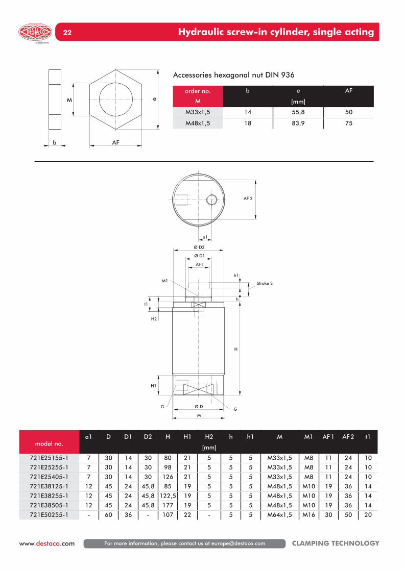
Hydraulic screw-in cylinder, single acting22
For more information, please contact us at [email protected] CLAMPING TECHNOLOGY
e
AF
M
b
Ø D
M
H
h
Stroke S
AF1
Ø D1
Ø D2
H1
H2
t1
G
h1M1
a1
G
AF 2
order no.
M
b e AF
[mm]
M33x1,5 14 55,8 50
M48x1,5 18 83,9 75
Accessories hexagonal nut DIN 936
model no.a1 D D1 D2 H H1 H2
[mm]
h h1 M M1 AF1 AF2 t1
721E25155-1 7 30 14 30 80 21 5 5 5 M33x1,5 M8 11 24 10
721E25255-1 7 30 14 30 98 21 5 5 5 M33x1,5 M8 11 24 10
721E25405-1 7 30 14 30 126 21 5 5 5 M33x1,5 M8 11 24 10
721E38125-1 12 45 24 45,8 85 19 5 5 5 M48x1,5 M10 19 36 14
721E38255-1 12 45 24 45,8 122,5 19 5 5 5 M48x1,5 M10 19 36 14
721E38505-1 12 45 24 45,8 177 19 5 5 5 M48x1,5 M10 19 36 14
721E50255-1 - 60 36 - 107 22 - 5 5 M64x1,5 M16 30 50 20
Hydraulic screw-in cylinder, double acting 23
For more information, please contact us at [email protected] www.destaco.comCLAMPING TECHNOLOGY
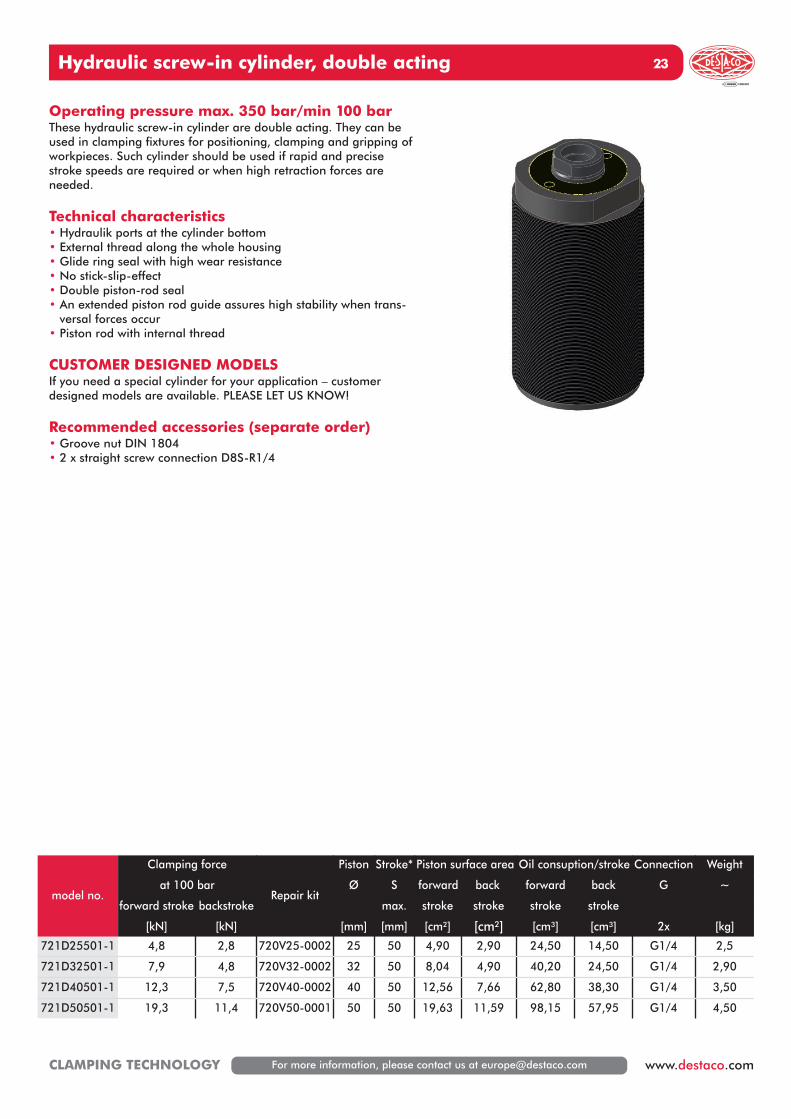
Operating pressure max. 350 bar/min 100 barThese hydraulic screw-in cylinder are double acting. They can beused in clamping fixtures for positioning, clamping and gripping ofworkpieces. Such cylinder should be used if rapid and precisestroke speeds are required or when high retraction forces areneeded.
Technical characteristics• Hydraulik ports at the cylinder bottom• External thread along the whole housing• Glide ring seal with high wear resistance• No stick-slip-effect• Double piston-rod seal• An extended piston rod guide assures high stability when trans-
versal forces occur• Piston rod with internal thread
CUSTOMER DESIGNED MODELSIf you need a special cylinder for your application – customerdesigned models are available. PLEASE LET US KNOW!
Recommended accessories (separate order)• Groove nut DIN 1804• 2 x straight screw connection D8S-R1/4
model no.
Clamping force
Repair kit
Piston Stroke* Piston surface area Oil consuption/stroke Connection Weight
at 100 bar Ø S forward back forward back G ~
forward stroke backstroke max. stroke stroke stroke stroke
[kN] [kN] [mm] [mm] [cm²] [cm²] [cm³] [cm³] 2x [kg]
721D25501-1 4,8 2,8 720V25-0002 25 50 4,90 2,90 24,50 14,50 G1/4 2,5
721D32501-1 7,9 4,8 720V32-0002 32 50 8,04 4,90 40,20 24,50 G1/4 2,90
721D40501-1 12,3 7,5 720V40-0002 40 50 12,56 7,66 62,80 38,30 G1/4 3,50
721D50501-1 19,3 11,4 720V50-0001 50 50 19,63 11,59 98,15 57,95 G1/4 4,50
Hydraulic screw-in cylinder, double acting24
For more information, please contact us at [email protected] CLAMPING TECHNOLOGY
M d1
b
s
90
Ø D1
M
H
h
Stroke S
H1
H2
AF1
Ø D1
Ø D3
t1
M1
Ø D2
h1
AF2
aa1
order no.
M
b d d1 s
[mm]
M50x1,5N 13 67 75 0,5
M56x1,5N 13 70 80 0,5
M68x1,5N 14 90 100 0,5
M80x2N 16 105 175 1
Accessories groove nut DIN 1804
model no.a a1 D D1 D2 D3 H H1 H2
[mm]
h h1 M M1 AF1 AF2 t
721D25501-1 14 10 48 16 47 15 133,5 5 15 9,5 5,5 M50x1,5 M10 13 41 20
721D32501-1 17 10 54 20 52 19 138 5 15 10 7 M56x1,5 M12 17 46 24
721D40501-1 22,5 5 65 25 64 24 144 5 15 11 8 M68x1,5 M16 21 55 32
721D50501-1 28 - 76 32 76 31 145,5 5 15 12 8 M80x2 M20 27 65 38
Hydraulic short stroke cylinder, double acting 25
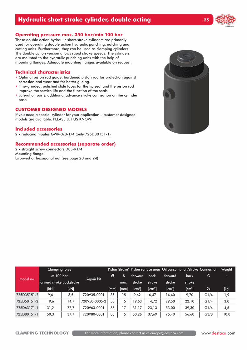
For more information, please contact us at [email protected] www.destaco.comCLAMPING TECHNOLOGY
Operating pressure max. 350 bar/min 100 barThese double action hydraulic short-stroke cylinders are primarily used for operating double action hydraulic punching, notching and cutting units. Furthermore, they can be used as clamping cylinders. The double action version allows rapid stroke speeds. The cylinders are mounted to the hydraulic punching units with the help of mounting flanges. Adequate mounting flanges available on request.
Technical characteristics• Optimal piston rod guide; hardened piston rod for protection against
corrosion and wear and for better gliding.• Fine-grinded, polished slide faces for the lip seal and the piston rod
improve the service life and the function of the seals.• Lateral oil ports, additional advance stroke connection on the cylinder
base
CUSTOMER DESIGNED MODELSIf you need a special cylinder for your application – customer designedmodels are available. PLEASE LET US KNOW!
Included accessories2 x reducing nipples GWR-3/8-1/4 (only 725D80151-1)
Recommended accessories (separate order)2 x straight screw connectors D8S-R1/4Mounting flangeGrooved or hexagonal nut (see page 20 and 24)
model no.
Clamping force
Repair kit
Piston Stroke* Piston surface area Oil consumption/stroke Connection Weight
at 100 bar Ø S forward back forward back G ~
forward stroke backstroke max. stroke stroke stroke stroke
[kN] [kN] [mm] [mm] [cm²] [cm²] [cm³] [cm³] 2x [kg]
725D35151-2 9,6 6,5 720V35-0001 35 15 9,62 6,47 14,40 9,70 G1/4 1,9
725D50151-2 19,6 14,7 720V50-0005-2 50 15 19,63 14,72 29,50 22,10 G1/4 3,0
725D63171-1 31,2 22,7 720V63-0001 63 17 31,17 23,13 53,00 39,30 G1/4 4,5
725D80151-1 50,3 37,7 720V80-0001 80 15 50,26 37,69 75,40 56,60 G3/8 10,0
Hydraulic short stroke cylinder, double acting26
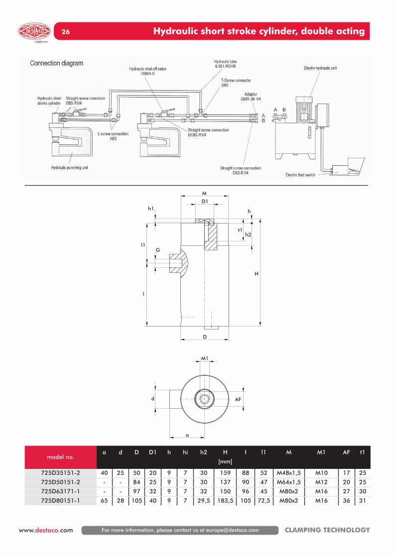
For more information, please contact us at [email protected] CLAMPING TECHNOLOGY
M
h1 h
h2
H
D
l1
l
G
t1
D1
d
a
AF
M1
model no.a d D D1 h hi h2 H
[mm]
I l1 M M1 AF t1
725D35151-2 40 25 50 20 9 7 30 159 88 52 M48x1,5 M10 17 25
725D50151-2 - - 84 25 9 7 30 137 90 47 M64x1,5 M12 20 25
725D63171-1 - - 97 32 9 7 32 150 96 45 M80x2 M16 27 30
725D80151-1 65 28 105 40 9 7 29,5 183,5 105 72,5 M80x2 M16 36 31
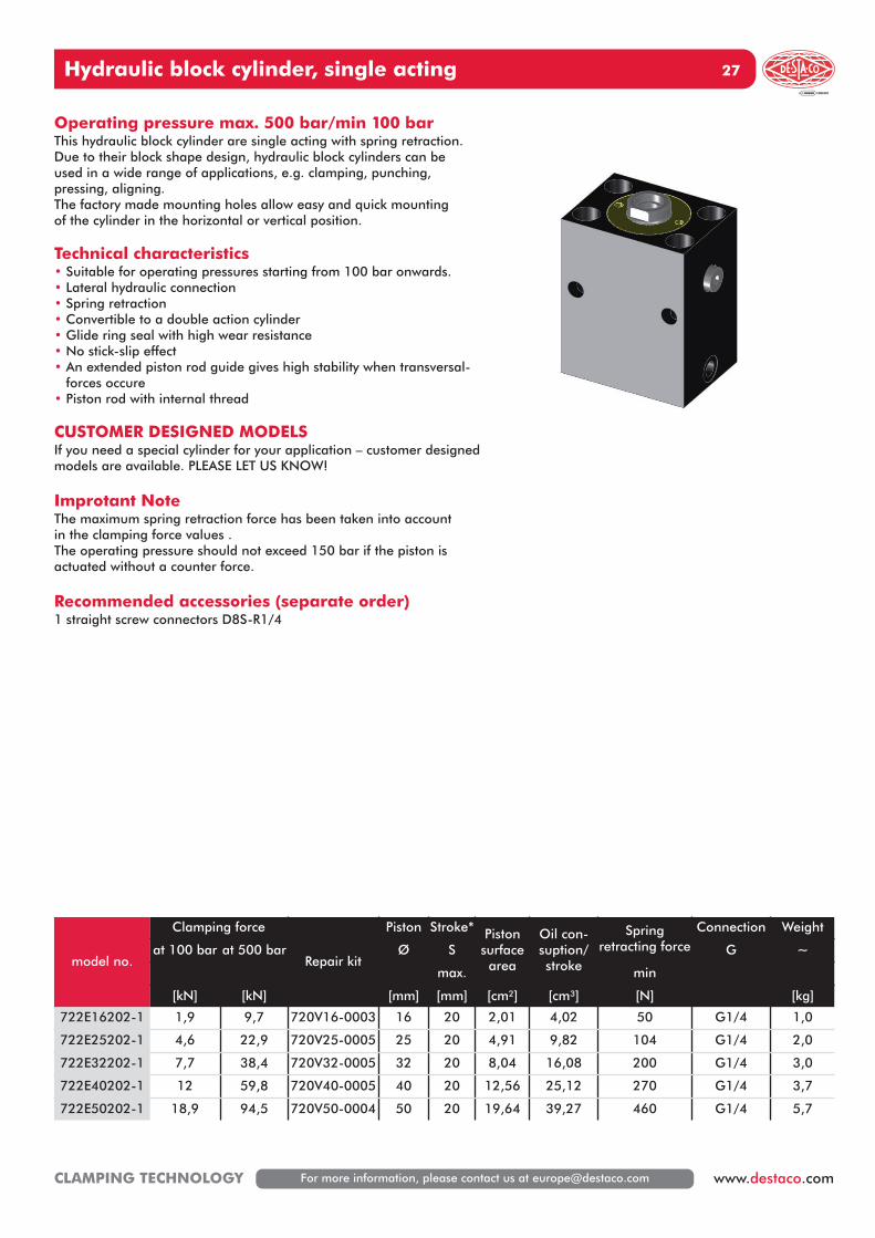
Hydraulic block cylinder, single acting 27
For more information, please contact us at [email protected] www.destaco.comCLAMPING TECHNOLOGY
model no.
Clamping force
Repair kit
Piston Stroke* Pistonsurfacearea
Oil con-suption/stroke
Spring retracting force
Connection Weight
at 100 bar at 500 bar Ø S G ~
max. min
[kN] [kN] [mm] [mm] [cm²] [cm³] [N] [kg]
722E16202-1 1,9 9,7 720V16-0003 16 20 2,01 4,02 50 G1/4 1,0
722E25202-1 4,6 22,9 720V25-0005 25 20 4,91 9,82 104 G1/4 2,0
722E32202-1 7,7 38,4 720V32-0005 32 20 8,04 16,08 200 G1/4 3,0
722E40202-1 12 59,8 720V40-0005 40 20 12,56 25,12 270 G1/4 3,7
722E50202-1 18,9 94,5 720V50-0004 50 20 19,64 39,27 460 G1/4 5,7
Operating pressure max. 500 bar/min 100 barThis hydraulic block cylinder are single acting with spring retraction.Due to their block shape design, hydraulic block cylinders can beused in a wide range of applications, e.g. clamping, punching,pressing, aligning.The factory made mounting holes allow easy and quick mountingof the cylinder in the horizontal or vertical position.
Technical characteristics• Suitable for operating pressures starting from 100 bar onwards.• Lateral hydraulic connection• Spring retraction• Convertible to a double action cylinder• Glide ring seal with high wear resistance• No stick-slip effect• An extended piston rod guide gives high stability when transversal-
forces occure• Piston rod with internal thread
CUSTOMER DESIGNED MODELSIf you need a special cylinder for your application – customer designedmodels are available. PLEASE LET US KNOW!
Improtant NoteThe maximum spring retraction force has been taken into accountin the clamping force values .The operating pressure should not exceed 150 bar if the piston isactuated without a counter force.
Recommended accessories (separate order)1 straight screw connectors D8S-R1/4
Hydraulic block cylinder, single acting28
For more information, please contact us at [email protected] CLAMPING TECHNOLOGY
d
d2
L
h
l1
AF
l4
l3
d1
t
d3
d1
G1/4
g b
e
a
M
model no.a b c d d1 d2 d3 e g
[mm]
h L l1 l3 l4 Mx depth
AF t t1
722E16202-1 60 35 17,5 10 6,5 9 11 40 22 6 111 44 30,5 11 M 6x15 8 6,8 4,5
722E25202-1 65 45 22,5 16 8,5 15 13,5 50 30 7 114 46 32 11 M10x15 13 9 5,5
722E32202-1 75 55 27,5 20 10,5 19 18 55 35 10 122 50 34 11 M12x18 17 11 7
722E40202-1 85 63 31,5 25 10,5 24 18 63 40 10 123 49 33 11 M16x25 21 11 7
722E50202-1 100 75 37,5 32 13 31 20 76 45 10 135 54 38 13 M20x30 27 13 8
Support is necessary in caseof operating pressure over 160 bar
Application example
Hydraulic block cylinder, double acting 29
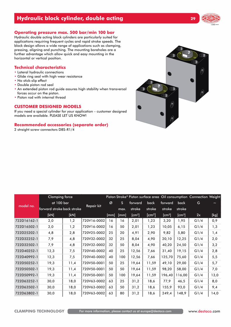
For more information, please contact us at [email protected] www.destaco.comCLAMPING TECHNOLOGY
Operating pressure max. 500 bar/min 100 barHydraulic double acting block cylinders are particularly suited forapplications requiring frequent cycles and rapid stroke speeds. Theblock design allows a wide range of applications such as clamping,pressing, aligning and punching. The mounting boreholes are afurther advantage which allow quick and easy mounting in the horizontal or vertical position.
Technical characteristics• Lateral hydraulic connections• Glide ring seal with high wear resistance• No stick-slip effect• Double piston rod seal• An extended piston rod guide assures high stability when transversal
forces occur on the piston.• Piston rod with internal thread
CUSTOMER DESIGNED MODELSIf you need a special cylinder for your application – customer designedmodels are available. PLEASE LET US KNOW!
Recommended accessories (separate order)2 straight screw connectors D8S-R1/4
model no.
Clamping force
Repair kit
Piston Stroke* Piston surface area Oil consumption Connection Weight
at 100 bar Ø S forward back forward back G ~
forward stroke back stroke max. stroke stroke stroke stroke
[kN] [kN] [mm] [mm] [cm²] [cm²] [cm³] [cm³] 2x [kg]
722D16162-1 2,0 1,2 720V16-0002 16 16 2,01 1,23 3,20 1,95 G1/4 0,9
722D16502-1 2,0 1,2 720V16-0002 16 50 2,01 1,23 10,05 6,15 G1/4 1,3
722D25202-1 4,8 2,8 720V25-0002 25 20 4,91 2,90 9,82 5,80 G1/4 1,4
722D32252-1 7,9 4,8 720V32-0002 32 25 8,04 4,90 20,10 12,25 G1/4 2,0
722D32502-1 7,9 4,8 720V32-0002 32 50 8,04 4,90 40,20 24,50 G1/4 3,2
722D40252-1 12,3 7,5 720V40-0002 40 25 12,56 7,66 31,40 19,15 G1/4 2,8
722D40992-1 12,3 7,5 720V40-0002 40 100 12,56 7,66 125,70 75,60 G1/4 5,5
722D50252-1 19,3 11,4 720V50-0001 50 25 19,64 11,59 49,10 29,00 G1/4 5,7
722D50502-1 19,3 11,4 720V50-0001 50 50 19,64 11,59 98,20 58,00 G1/4 7,0
722D50992-1 19,3 11,4 720V50-0001 50 100 19,64 11,59 196,40 116,00 G1/4 13,0
722D63252-1 30,0 18,0 720V63-0002 63 25 31,2 18,6 77,9 46,5 G1/4 8,0
722D63502-1 30,0 18,0 720V63-0002 63 50 31,2 18,6 155,9 93,0 G1/4 9,4
722D63802-1 30,0 18,0 720V63-0002 63 80 31,2 18,6 249,4 148,9 G1/4 14,0
Hydraulic block cylinder, double acting30
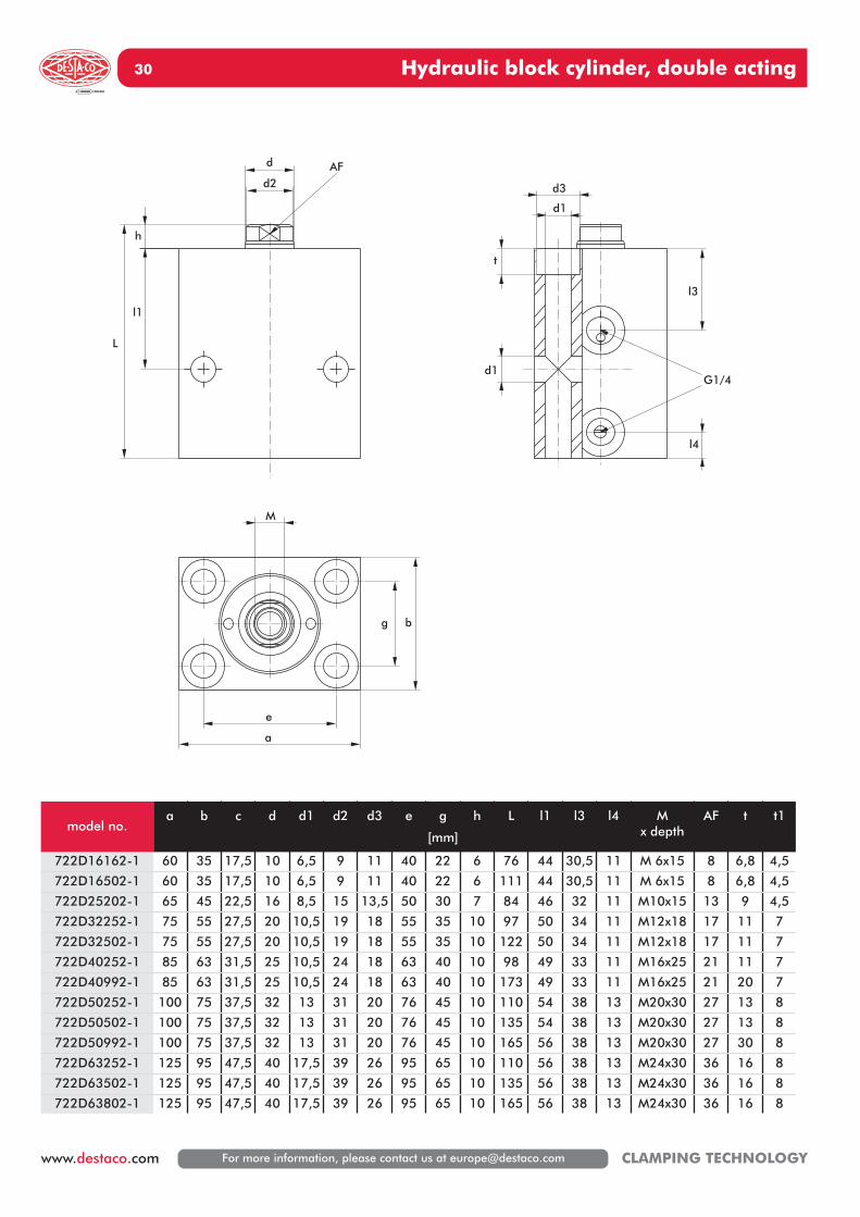
For more information, please contact us at [email protected] CLAMPING TECHNOLOGY
d
d2
L
h
l1
AF
l4
l3
d1
t
d3
d1
G1/4
g b
e
a
M
model no.a b c d d1 d2 d3 e g
[mm]
h L l1 l3 l4 Mx depth
AF t t1
722D16162-1 60 35 17,5 10 6,5 9 11 40 22 6 76 44 30,5 11 M 6x15 8 6,8 4,5
722D16502-1 60 35 17,5 10 6,5 9 11 40 22 6 111 44 30,5 11 M 6x15 8 6,8 4,5
722D25202-1 65 45 22,5 16 8,5 15 13,5 50 30 7 84 46 32 11 M10x15 13 9 4,5
722D32252-1 75 55 27,5 20 10,5 19 18 55 35 10 97 50 34 11 M12x18 17 11 7
722D32502-1 75 55 27,5 20 10,5 19 18 55 35 10 122 50 34 11 M12x18 17 11 7
722D40252-1 85 63 31,5 25 10,5 24 18 63 40 10 98 49 33 11 M16x25 21 11 7
722D40992-1 85 63 31,5 25 10,5 24 18 63 40 10 173 49 33 11 M16x25 21 20 7
722D50252-1 100 75 37,5 32 13 31 20 76 45 10 110 54 38 13 M20x30 27 13 8
722D50502-1 100 75 37,5 32 13 31 20 76 45 10 135 54 38 13 M20x30 27 13 8
722D50992-1 100 75 37,5 32 13 31 20 76 45 10 165 56 38 13 M20x30 27 30 8
722D63252-1 125 95 47,5 40 17,5 39 26 95 65 10 110 56 38 13 M24x30 36 16 8
722D63502-1 125 95 47,5 40 17,5 39 26 95 65 10 135 56 38 13 M24x30 36 16 8
722D63802-1 125 95 47,5 40 17,5 39 26 95 65 10 165 56 38 13 M24x30 36 16 8
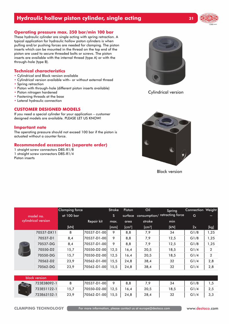
Hydraulic hollow piston cylinder, single acting 31
For more information, please contact us at [email protected] www.destaco.comCLAMPING TECHNOLOGY
model no.cylindrical version
Clamping force Stroke Piston Oil Spring retracting force
Connection Weight
at 100 bar S surface consumption/ G ~
Repair kit max. area stroke min
[kN] [mm] [cm²] [cm³] [kN] 2x [kg]
70537-DX11 8 70537-D1-00 9 8,8 7,9 34 G1/8 1,25
70537-D1 8,4 70537-D1-00 9 8,8 7,9 12,5 G1/8 1,25
70537-DG 8,4 70537-D1-00 9 8,8 7,9 12,5 G1/8 1,25
70550-D2 15,7 70550-D2-00 12,5 16,4 20,5 18,5 G1/4 2
70550-DG 15,7 70550-D2-00 12,5 16,4 20,5 18,5 G1/4 2
70562-D2 23,9 70562-D1-00 15,5 24,8 38,4 32 G1/4 2,8
70562-DG 23,9 70562-D1-00 15,5 24,8 38,4 32 G1/4 2,8
block version
723E38092-1 8 70537-D1-00 9 8,8 7,9 34 G1/8 1,5
723E51122-1 15,7 70550-D2-00 12,5 16,4 20,5 18,5 G1/4 2,5
723E63152-1 23,9 70562-D1-00 15,5 24,8 28,4 32 G1/4 3,3
Operating pressure max. 350 bar/min 100 barThese hydraulic cylinder are single acting with spring retraction. Atypical application for hydraulic hollow piston cylinders is whenpulling and/or pushing forces are needed for clamping. The pistoninserts which can be mounted in the thread on the top end of thepiston are used to secure threaded bolts or screws. The piston inserts are available with the internal thread (type A) or with thethrough-hole (type B).
Technical characteristics• Cylindrical and Block version available• Cylindrical version available with– or without external thread• Spring retraction• Piston with through-hole (different piston inserts available)• Piston nitrogen hardened• Fastening threads at the base• Lateral hydraulic connection
CUSTOMER DESIGNED MODELSIf you need a special cylinder for your application – customer designed models are available. PLEASE LET US KNOW!
Important noteThe operating pressure should not exceed 100 bar if the piston isactuated without a counter force.
Recommended accessories (separate order)1 straight screw connectors D8S-R1/81 straight screw connectors D8S-R1/4Piston inserts
Cylindrical version
Block version
Hydraulic hollow piston cylinder, single acting32
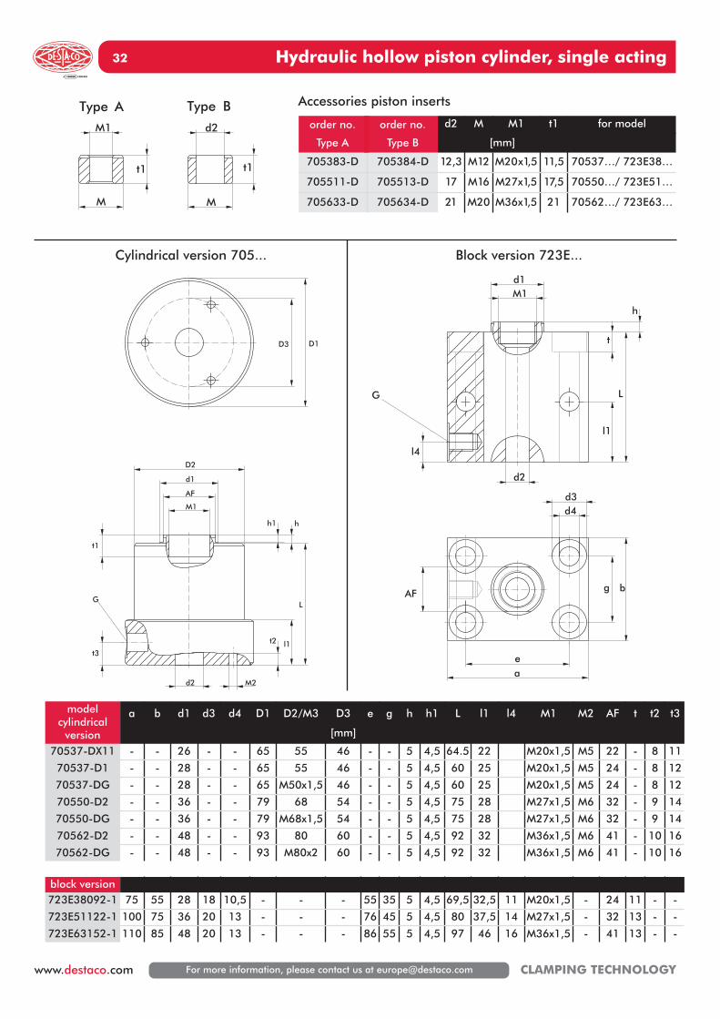
For more information, please contact us at [email protected] CLAMPING TECHNOLOGY
D3 D1
t2
t3
d2 M2
AF
d1
M1
h1 h
l1
L
t1
D2
G
Accessories piston inserts
modelcylindrical
version
a b d1 d3 d4 D1 D2/M3 D3
[mm]
e g h h1 L l1 l4 M1 M2 AF t t2 t3
70537-DX11 - - 26 - - 65 55 46 - - 5 4,5 64.5 22 M20x1,5 M5 22 - 8 11
70537-D1 - - 28 - - 65 55 46 - - 5 4,5 60 25 M20x1,5 M5 24 - 8 12
70537-DG - - 28 - - 65 M50x1,5 46 - - 5 4,5 60 25 M20x1,5 M5 24 - 8 12
70550-D2 - - 36 - - 79 68 54 - - 5 4,5 75 28 M27x1,5 M6 32 - 9 14
70550-DG - - 36 - - 79 M68x1,5 54 - - 5 4,5 75 28 M27x1,5 M6 32 - 9 14
70562-D2 - - 48 - - 93 80 60 - - 5 4,5 92 32 M36x1,5 M6 41 - 10 16
70562-DG - - 48 - - 93 M80x2 60 - - 5 4,5 92 32 M36x1,5 M6 41 - 10 16
block version723E38092-1 75 55 28 18 10,5 - - - 55 35 5 4,5 69,5 32,5 11 M20x1,5 - 24 11 - -
723E51122-1 100 75 36 20 13 - - - 76 45 5 4,5 80 37,5 14 M27x1,5 - 32 13 - -
723E63152-1 110 85 48 20 13 - - - 86 55 5 4,5 97 46 16 M36x1,5 - 41 13 - -
d2
l4
l1
L
h
d1
t
M1
G
g b
ea
AF
d4d3
M1
M
d2
M
t1 t1
Type BType A
Cylindrical version 705... Block version 723E...
order no.
Type A
order no.
Type B
d2 M M1 t1 for model
[mm]
705383-D 705384-D 12,3 M12 M20x1,5 11,5 70537…/ 723E38…
705511-D 705513-D 17 M16 M27x1,5 17,5 70550…/ 723E51…
705633-D 705634-D 21 M20 M36x1,5 21 70562…/ 723E63…

Hydraulic hollow piston cylinder, double acting 33
For more information, please contact us at [email protected] www.destaco.comCLAMPING TECHNOLOGY
model no.cylindrical version
Clamping force Stroke* Piston surface area Oil consumption Connection Weight
at 100 bar S forward back forward back G ~
forward stroke back stroke Repair kit max. stroke stroke stroke stroke
[kN] [kN] [mm] [cm²] [cm²] [cm³] [cm³] 2x [kg]
7411-2 8,6 5,9 7411-2-00 10 8,8 6,0 8,8 6,0 G1/4 0,9
7412-2 12,9 8,3 7412-2-00 15 13,2 8,4 21,1 13,4 G1/4 1,5
7413-2 18,1 12,7 7413-2-00 24 18,4 15,0 44,1 36,0 G1/4 2,0
7414-2 26,2 20 7414-2-00 24 26,7 20,4 64,1 49,0 G1/4 2,6
block version723D38102-2 8,6 5,9 7411-1-00 10 8,8 6,0 8,8 6,0 G1/4 1,3
723D48152-2 12,9 8,3 7412-1-00 15 13,2 8,4 21,1 13,4 G1/4 1,8
723D57242-2 18,1 12,7 7413-1-00 24 18,4 15,0 44,1 36,0 G1/4 2,5
723D68242-2 26,2 20 7414-1-00 24 26,7 20,4 64,1 49,0 G1/4 3,1
Operating pressure max. 350 bar/min 100 barHydraulic hollow piston cylinders can solve many clamping prob-lems because they can also be used as pulling cylinders due to thehollow piston combined with a tie rod. The double action principleallows short stroke times and high retraction forces, i.e. clampingforces in the reverse stroke direction.
Technical characteristics• Piston with through-hole and with internal thread• 2 fastening threads at the base• Lateral hydraulic connections
CUSTOMER DESIGNED MODELSIf you need a special cylinder for your application – customer designed models are available. PLEASE LET US KNOW!
Important noteThe operating pressure should not exceed 250 bar if the piston isactuated without a counter force.
Recommended accessories (separate order)2 straight screw connectors D8S-R1/4
Cylindrical version
Block version
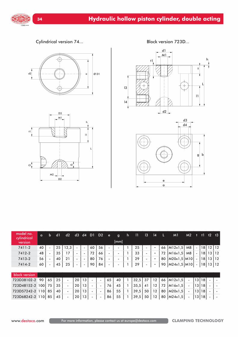
Hydraulic hollow piston cylinder, double acting34
For more information, please contact us at [email protected] CLAMPING TECHNOLOGY
D2
M2
t3 t2
t1l1
h
L
D3
M1
a Ø D1d2
g b
ea
d4d3
l4
l3L
h
l1
d2
d1M1
t1
t
model no.cylindrical
version
a b d1 d2 d3 d4 D1 D2 e g
[mm]
h l1 l3 l4 L M1 M2 t t1 t2 t3
7411-2 40 - 25 12,3 - - 60 56 - - 1 25 - - 66 M12x1,5 M8 - 18 12 12
7412-2 48 - 35 17 - - 72 66 - - 1 33 - - 72 M16x1,5 M8 - 18 13 12
7413-2 56 - 40 21 - - 80 76 - - 1 29 - - 80 M20x1,5 M10 - 18 13 12
7414-2 60 - 45 25 - - 90 84 - - 1 29 - - 90 M24x1,5 M10 - 18 13 12
block version723D38102-2 90 65 25 - 20 13 - - 65 40 1 32,5 37 12 66 M12x1,5 - 13 18 - -
723D48152-2 100 75 35 - 20 13 - - 76 45 1 35,5 41 12 72 M16x1,5 - 13 18 - -
723D57242-2 110 85 40 - 20 13 - - 86 55 1 39,5 50 12 80 M20x1,5 - 13 18 - -
723D68242-2 110 85 45 - 20 13 - - 86 55 1 39,5 50 12 80 M24x1,5 - 13 18 - -
Cylindrical version 74... Block version 723D...
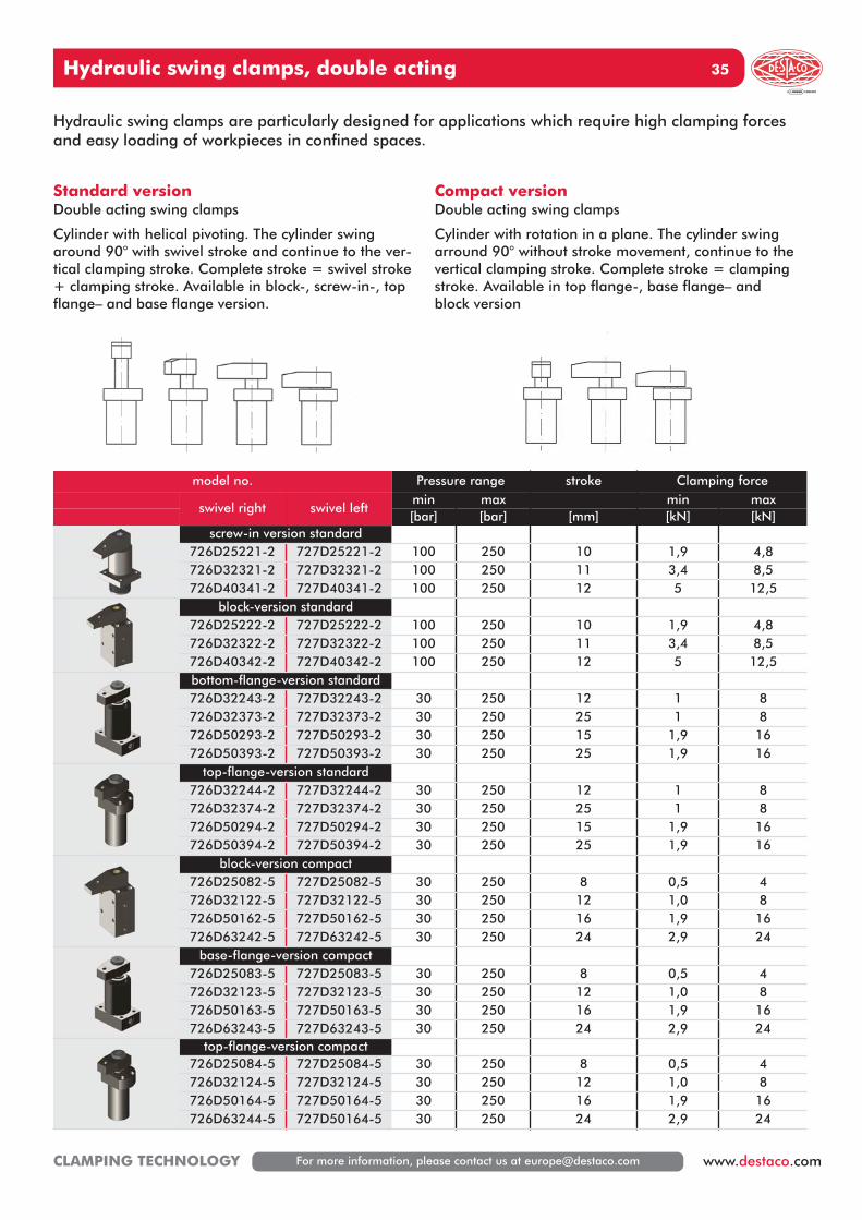
Hydraulic swing clamps, double acting 35
For more information, please contact us at [email protected] www.destaco.comCLAMPING TECHNOLOGY
Hydraulic swing clamps are particularly designed for applications which require high clamping forcesand easy loading of workpieces in confined spaces.
Standard versionDouble acting swing clamps
Cylinder with helical pivoting. The cylinder swingaround 90° with swivel stroke and continue to the ver-tical clamping stroke. Complete stroke = swivel stroke+ clamping stroke. Available in block-, screw-in-, topflange– and base flange version.
Compact versionDouble acting swing clamps
Cylinder with rotation in a plane. The cylinder swingarround 90° without stroke movement, continue to thevertical clamping stroke. Complete stroke = clampingstroke. Available in top flange-, base flange– andblock version
model no. Pressure range stroke Clamping force
swivel right swivel leftmin max min max[bar] [bar] [mm] [kN] [kN]
screw-in version standard726D25221-2 727D25221-2 100 250 10 1,9 4,8726D32321-2 727D32321-2 100 250 11 3,4 8,5726D40341-2 727D40341-2 100 250 12 5 12,5
block-version standard726D25222-2 727D25222-2 100 250 10 1,9 4,8726D32322-2 727D32322-2 100 250 11 3,4 8,5726D40342-2 727D40342-2 100 250 12 5 12,5bottom-flange-version standard726D32243-2 727D32243-2 30 250 12 1 8726D32373-2 727D32373-2 30 250 25 1 8726D50293-2 727D50293-2 30 250 15 1,9 16726D50393-2 727D50393-2 30 250 25 1,9 16
top-flange-version standard726D32244-2 727D32244-2 30 250 12 1 8726D32374-2 727D32374-2 30 250 25 1 8726D50294-2 727D50294-2 30 250 15 1,9 16726D50394-2 727D50394-2 30 250 25 1,9 16
block-version compact726D25082-5 727D25082-5 30 250 8 0,5 4726D32122-5 727D32122-5 30 250 12 1,0 8726D50162-5 727D50162-5 30 250 16 1,9 16726D63242-5 727D63242-5 30 250 24 2,9 24
base-flange-version compact726D25083-5 727D25083-5 30 250 8 0,5 4726D32123-5 727D32123-5 30 250 12 1,0 8726D50163-5 727D50163-5 30 250 16 1,9 16726D63243-5 727D63243-5 30 250 24 2,9 24
top-flange-version compact726D25084-5 727D25084-5 30 250 8 0,5 4726D32124-5 727D32124-5 30 250 12 1,0 8726D50164-5 727D50164-5 30 250 16 1,9 16726D63244-5 727D50164-5 30 250 24 2,9 24
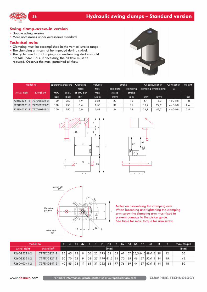
Hydraulic swing clamps – Standard version36
For more information, please contact us at [email protected] CLAMPING TECHNOLOGY
Swing clamp-screw-in version• Double acting version• More accessories under accessories standard
Technical note:• Clamping must be accomplished in the vertical stroke range.• The clamping arm cannot be impeded during swivel.• The cycle time for a clamping or a unclamping stroke should
not fall under 1,5 s. If necessary, the oil flow must be reduced. Observe the max. permitted oil flow.
75°
30°
R2
e c
swivel left90°
swivel right90°
d2
h7h6
S
t
h2
h3M
H1
a
h
H
d1
Clampingposition
model no. operating pressure Clamping volume stroke Ol consumption Connection Weight
force flow complete clamping clamping unclamping G
swivel right swivel left min. max. at 100 bar max. stroke stroke
[bar] [bar] [kN] [l/min] [mm] [mm] [cm³] [cm³] [kg]
726D25221-2 727D25221-2 100 250 1,9 0,26 27 10 6,4 13,3 4x G1/8 1,85
726D32321-2 727D32321-2 100 250 3,4 0,53 31 11 13,2 24,9 4x G1/8 2,6
726D40341-2 727D40341-2 100 250 5,0 0,87 34 12 21,8 42,7 4x G1/8 3,5
model no. a c d1 d2 e f H H1 h h2 h3 h6 h7 M R t max. torque
swivel right swivel left [mm] [Nm]
726D25221-2 727D25221-2 25 65 18 9 50 23 173 53 55 61 57 35,5 44,5 48x1,5 29 12 30
726D32321-2 727D32321-2 30 70 22 9 56 27 199 61,5 64 70 65 46 57 52x1,5 34 15 45
726D40341-2 727D40341-2 40 85 28 11 65 31 222 68 77 76 69 44 57 62x1,5 44 18 80
Notes on assembling the clamping armWhen loosening and tightening the clampingarm screw the clamping arm must fixed toprevent damage to the piston guide.See table for max. torque for arm screw.
Hydraulic swing clamps – Standard version 37
For more information, please contact us at [email protected] www.destaco.comCLAMPING TECHNOLOGY
Swing clamp-block version• Double acting version
Optional• Position control (E)• More accessories under accessories standard
Technical note:• Clamping must be accomplished in the vertical stroke range.• The clamping arm cannot be impeded during swivel.• The cycle time for a clamping or a unclamping stroke should
not fall under 1,5 s. If necessary, the oil flow must be reduced. Observe the max. permitted oil flow.
model no. operating pressure Clamping Volume Stroke Oil consumption Connection Weight
force flow complete clamping clamping unclamping G
swivel right swivel left min. max. at 100 bar max. stroke stroke
[bar] [bar] [kN] [l/min] [mm] [mm] [cm³] [cm³] [kg]
726D25222-2 727D25222-2 100 250 1,9 0,26 27 10 6,4 13,3 2x G1/8 2,2
726D32322-2 727D32322-2 100 250 3,4 0,53 31 11 13,2 24,9 2x G1/8 3,5
726D40342-2 727D40342-2 100 250 5 0,87 34 12 21,8 42,7 2x G1/8 4,9
S
t1
t2
h
H
h1
h7
h6
d1
a
f
G
e c
Ød 2 Ød 3e1
c1
d2
swivel left90°
swivel right90°
Clampingposition
model no. a c c1 d1 d2 d3 e e1 f H h h1 h6 h7 t1 t2 max. Torque
swivel right swivel left [mm] [Nm]
726D25222-2 727D25222-2 25 65 45 18 8,5 13,5 50 30 20,5 165 55 110 10 70,5 35 85 30
726D32322-2 727D32322-2 30 75 55 22 10,5 18 55 35 25,5 194 64 130 12,5 79 45,5 100,5 45
726D40342-2 727D40342-2 40 85 63 28 10,5 18 63 40 29,5 217 77 140 14 91 48,5 108,5 80
Notes on assembling the clamping armWhen loosening and tightening the clampingarm screw the clamping arm must fixed toprevent damage to the piston guide.See table for max. torque for arm screw.
Hydraulic swing clamps – Standard version38
For more information, please contact us at [email protected] CLAMPING TECHNOLOGY
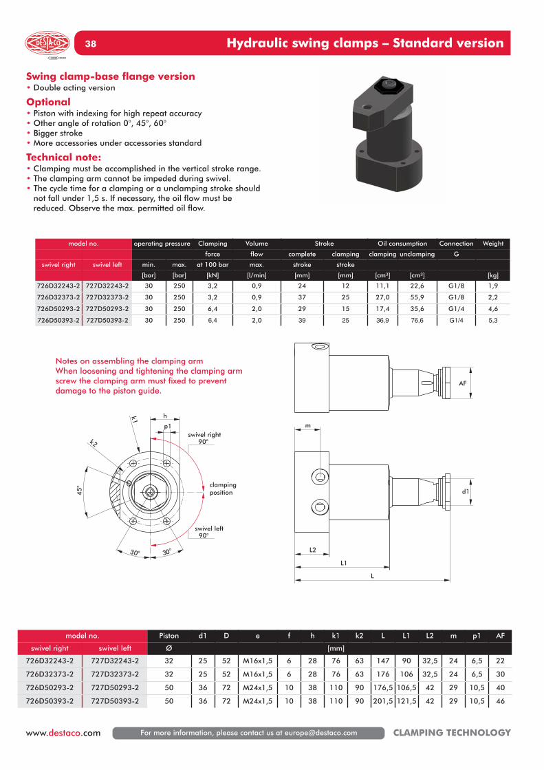
Swing clamp-base flange version• Double acting version
Optional• Piston with indexing for high repeat accuracy• Other angle of rotation 0°, 45°, 60°• Bigger stroke• More accessories under accessories standard
Technical note:• Clamping must be accomplished in the vertical stroke range.• The clamping arm cannot be impeded during swivel.• The cycle time for a clamping or a unclamping stroke should
not fall under 1,5 s. If necessary, the oil flow must be reduced. Observe the max. permitted oil flow.
m
d1
L2
L1
L
30° 30°
k2
45°
h
swivel right90°
swivel left90°
k1
p1
AF
clampingposition
model no. operating pressure Clamping Volume Stroke Oil consumption Connection Weight
force flow complete clamping clamping unclamping G
swivel right swivel left min. max. at 100 bar max. stroke stroke
[bar] [bar] [kN] [l/min] [mm] [mm] [cm³] [cm³] [kg]
726D32243-2 727D32243-2 30 250 3,2 0,9 24 12 11,1 22,6 G1/8 1,9
726D32373-2 727D32373-2 30 250 3,2 0,9 37 25 27,0 55,9 G1/8 2,2
726D50293-2 727D50293-2 30 250 6,4 2,0 29 15 17,4 35,6 G1/4 4,6
726D50393-2 727D50393-2 30 250 6,4 2,0 39 25 36,9 76,6 G1/4 5,3
model no. Piston d1 D e f h k1 k2 L L1 L2 m p1 AF
swivel right swivel left Ø [mm]
726D32243-2 727D32243-2 32 25 52 M16x1,5 6 28 76 63 147 90 32,5 24 6,5 22
726D32373-2 727D32373-2 32 25 52 M16x1,5 6 28 76 63 176 106 32,5 24 6,5 30
726D50293-2 727D50293-2 50 36 72 M24x1,5 10 38 110 90 176,5 106,5 42 29 10,5 40
726D50393-2 727D50393-2 50 36 72 M24x1,5 10 38 110 90 201,5 121,5 42 29 10,5 46
Notes on assembling the clamping armWhen loosening and tightening the clamping armscrew the clamping arm must fixed to prevent damage to the piston guide.
Hydraulic swing clamps – Standard version 39
For more information, please contact us at [email protected] www.destaco.comCLAMPING TECHNOLOGY
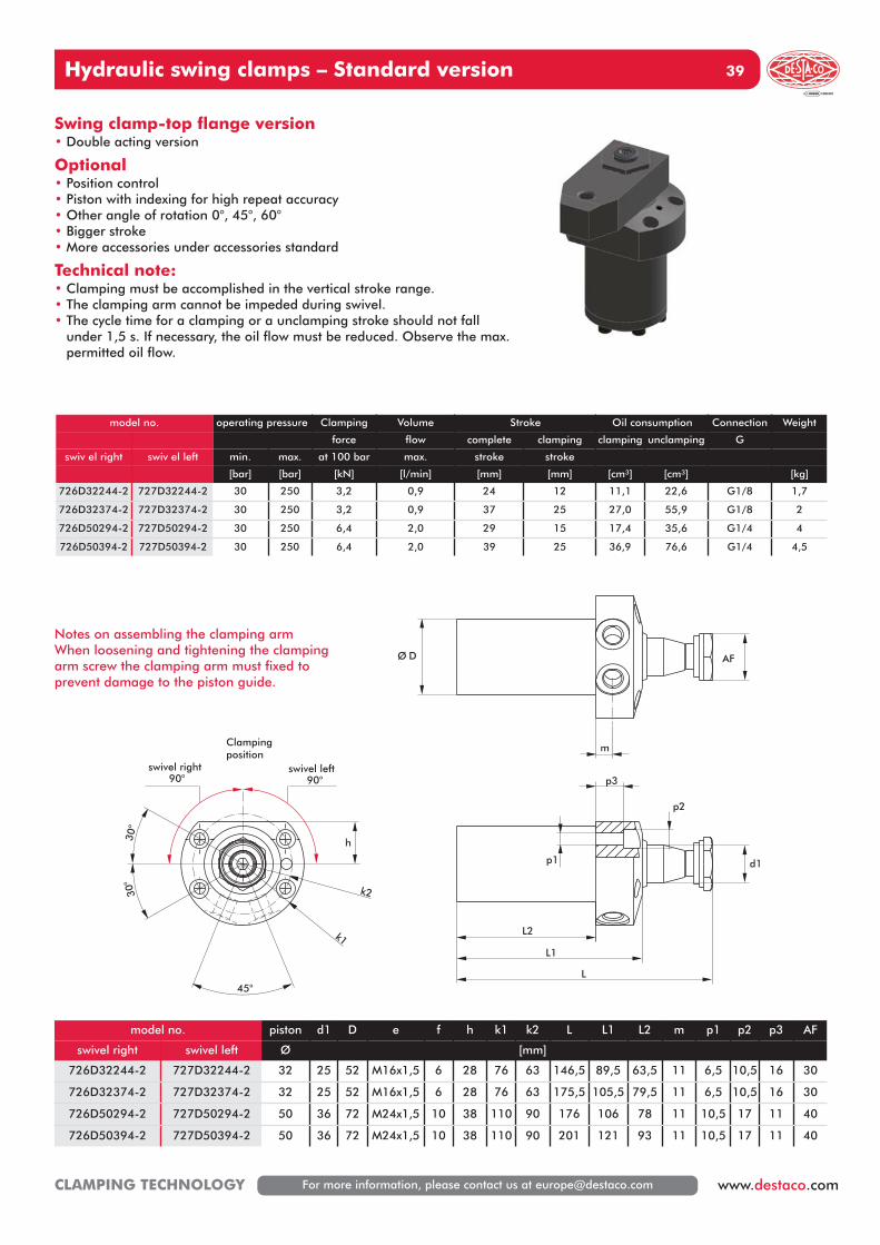
Swing clamp-top flange version• Double acting version
Optional• Position control• Piston with indexing for high repeat accuracy• Other angle of rotation 0°, 45°, 60°• Bigger stroke• More accessories under accessories standard
Technical note:• Clamping must be accomplished in the vertical stroke range.• The clamping arm cannot be impeded during swivel.• The cycle time for a clamping or a unclamping stroke should not fall
under 1,5 s. If necessary, the oil flow must be reduced. Observe the max.permitted oil flow.
d1
L2
L1
L
p1
p2
p3
45°
30°
30°
k2
swivel right90°
swivel left90°
h
k1
m
AFØ D
Clampingposition
model no. operating pressure Clamping Volume Stroke Oil consumption Connection Weight
force flow complete clamping clamping unclamping G
swiv el right swiv el left min. max. at 100 bar max. stroke stroke
[bar] [bar] [kN] [l/min] [mm] [mm] [cm³] [cm³] [kg]
726D32244-2 727D32244-2 30 250 3,2 0,9 24 12 11,1 22,6 G1/8 1,7
726D32374-2 727D32374-2 30 250 3,2 0,9 37 25 27,0 55,9 G1/8 2
726D50294-2 727D50294-2 30 250 6,4 2,0 29 15 17,4 35,6 G1/4 4
726D50394-2 727D50394-2 30 250 6,4 2,0 39 25 36,9 76,6 G1/4 4,5
model no. piston d1 D e f h k1 k2 L L1 L2 m p1 p2 p3 AF
swivel right swivel left Ø [mm]
726D32244-2 727D32244-2 32 25 52 M16x1,5 6 28 76 63 146,5 89,5 63,5 11 6,5 10,5 16 30
726D32374-2 727D32374-2 32 25 52 M16x1,5 6 28 76 63 175,5 105,5 79,5 11 6,5 10,5 16 30
726D50294-2 727D50294-2 50 36 72 M24x1,5 10 38 110 90 176 106 78 11 10,5 17 11 40
726D50394-2 727D50394-2 50 36 72 M24x1,5 10 38 110 90 201 121 93 11 10,5 17 11 40
Notes on assembling the clamping armWhen loosening and tightening the clampingarm screw the clamping arm must fixed toprevent damage to the piston guide.
Hydraulic swing clamps – compact version40
For more information, please contact us at [email protected] CLAMPING TECHNOLOGY
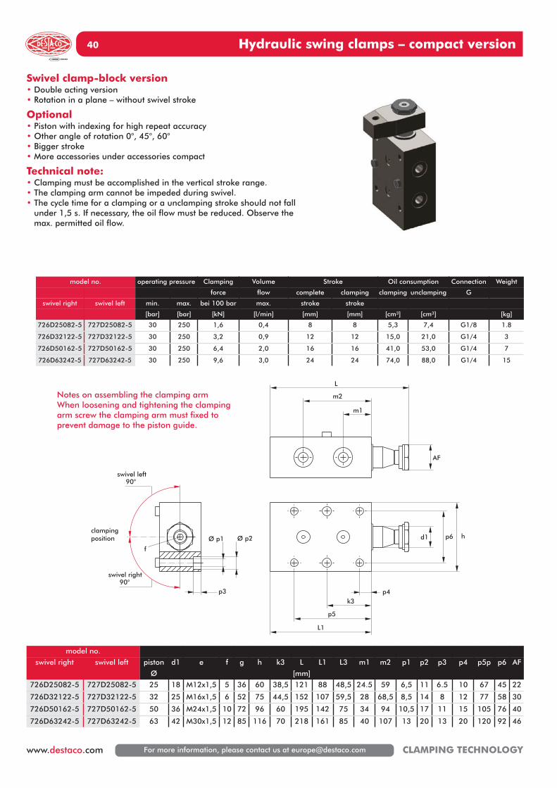
Swivel clamp-block version• Double acting version• Rotation in a plane – without swivel stroke
Optional• Piston with indexing for high repeat accuracy• Other angle of rotation 0°, 45°, 60°• Bigger stroke• More accessories under accessories compact
Technical note:• Clamping must be accomplished in the vertical stroke range.• The clamping arm cannot be impeded during swivel.• The cycle time for a clamping or a unclamping stroke should not fall
under 1,5 s. If necessary, the oil flow must be reduced. Observe themax. permitted oil flow.
d1
L1
p4k3
p5
p6 h
AF
m1
m2
L
Ø p1 Ø p2
p3
swivel left90°
swivel right90°
f
clampingposition
Notes on assembling the clamping armWhen loosening and tightening the clampingarm screw the clamping arm must fixed toprevent damage to the piston guide.
model no. operating pressure Clamping Volume Stroke Oil consumption Connection Weight
force flow complete clamping clamping unclamping G
swivel right swivel left min. max. bei 100 bar max. stroke stroke
[bar] [bar] [kN] [l/min] [mm] [mm] [cm³] [cm³] [kg]
726D25082-5 727D25082-5 30 250 1,6 0,4 8 8 5,3 7,4 G1/8 1.8
726D32122-5 727D32122-5 30 250 3,2 0,9 12 12 15,0 21,0 G1/4 3
726D50162-5 727D50162-5 30 250 6,4 2,0 16 16 41,0 53,0 G1/4 7
726D63242-5 727D63242-5 30 250 9,6 3,0 24 24 74,0 88,0 G1/4 15
model no.
swivel right swivel left piston d1 e f g h k3 L L1 L3 m1 m2 p1 p2 p3 p4 p5p p6 AF
Ø [mm]
726D25082-5 727D25082-5 25 18 M12x1,5 5 36 60 38,5 121 88 48,5 24.5 59 6,5 11 6.5 10 67 45 22
726D32122-5 727D32122-5 32 25 M16x1,5 6 52 75 44,5 152 107 59,5 28 68,5 8,5 14 8 12 77 58 30
726D50162-5 727D50162-5 50 36 M24x1,5 10 72 96 60 195 142 75 34 94 10,5 17 11 15 105 76 40
726D63242-5 727D63242-5 63 42 M30x1,5 12 85 116 70 218 161 85 40 107 13 20 13 20 120 92 46
Hydraulic swing clamps – compact version 41
For more information, please contact us at [email protected] www.destaco.comCLAMPING TECHNOLOGY
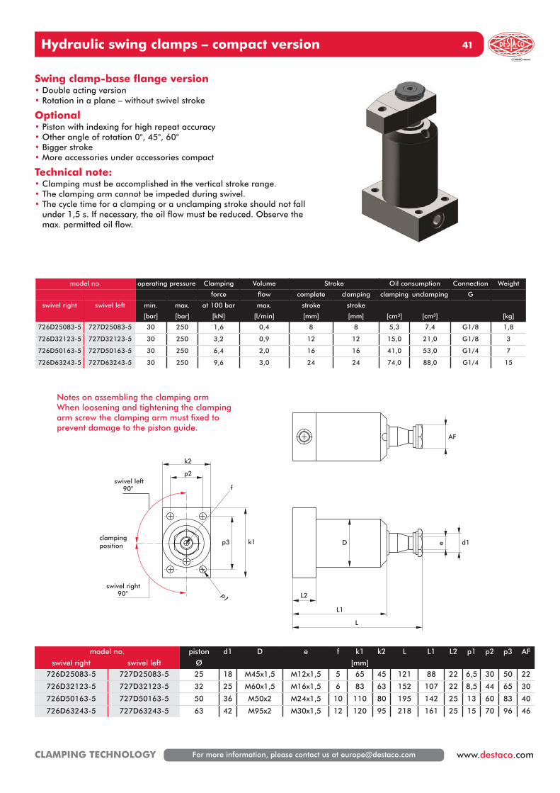
Swing clamp-base flange version• Double acting version• Rotation in a plane – without swivel stroke
Optional• Piston with indexing for high repeat accuracy• Other angle of rotation 0°, 45°, 60°• Bigger stroke• More accessories under accessories compact
Technical note:• Clamping must be accomplished in the vertical stroke range.• The clamping arm cannot be impeded during swivel.• The cycle time for a clamping or a unclamping stroke should not fall
under 1,5 s. If necessary, the oil flow must be reduced. Observe themax. permitted oil flow.
d1D e
L
L2
L1
k1
k2
p2
p3
p1
f
AF
swivel left90°
swivel right90°
clampingposition
Notes on assembling the clamping armWhen loosening and tightening the clampingarm screw the clamping arm must fixed toprevent damage to the piston guide.
model no. operating pressure Clamping Volume Stroke Oil consumption Connection Weight
force flow complete clamping clamping unclamping G
swivel right swivel left min. max. at 100 bar max. stroke stroke
[bar] [bar] [kN] [l/min] [mm] [mm] [cm³] [cm³] [kg]
726D25083-5 727D25083-5 30 250 1,6 0,4 8 8 5,3 7,4 G1/8 1,8
726D32123-5 727D32123-5 30 250 3,2 0,9 12 12 15,0 21,0 G1/8 3
726D50163-5 727D50163-5 30 250 6,4 2,0 16 16 41,0 53,0 G1/4 7
726D63243-5 727D63243-5 30 250 9,6 3,0 24 24 74,0 88,0 G1/4 15
model no. piston d1 D e f k1 k2 L L1 L2 p1 p2 p3 AF
swivel right swivel left Ø [mm]
726D25083-5 727D25083-5 25 18 M45x1,5 M12x1,5 5 65 45 121 88 22 6,5 30 50 22
726D32123-5 727D32123-5 32 25 M60x1,5 M16x1,5 6 83 63 152 107 22 8,5 44 65 30
726D50163-5 727D50163-5 50 36 M50x2 M24x1,5 10 110 80 195 142 25 13 60 83 40
726D63243-5 727D63243-5 63 42 M95x2 M30x1,5 12 120 95 218 161 25 15 70 96 46
Hydraulic swing clamps – compact version42
For more information, please contact us at [email protected] CLAMPING TECHNOLOGY
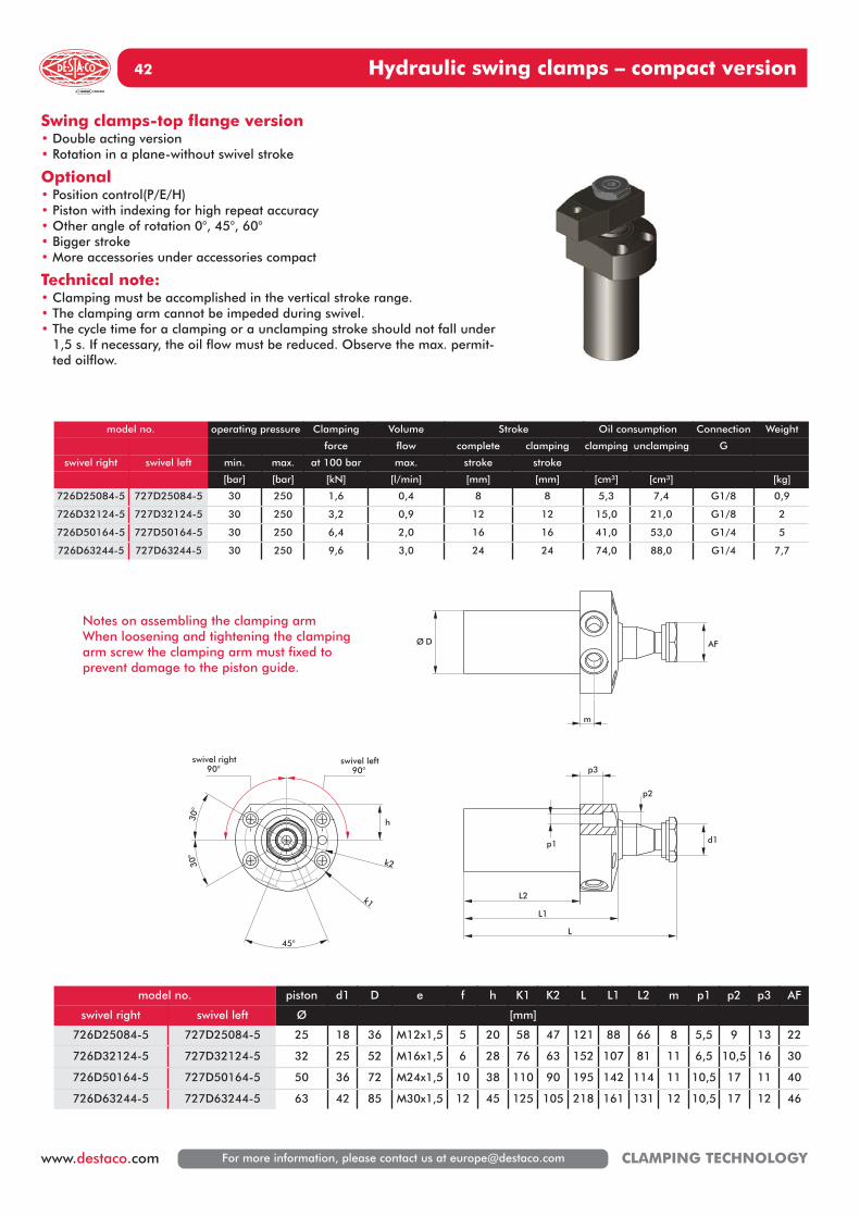
Swing clamps-top flange version• Double acting version• Rotation in a plane-without swivel stroke
Optional• Position control(P/E/H)• Piston with indexing for high repeat accuracy• Other angle of rotation 0°, 45°, 60°• Bigger stroke• More accessories under accessories compact
Technical note:• Clamping must be accomplished in the vertical stroke range.• The clamping arm cannot be impeded during swivel.• The cycle time for a clamping or a unclamping stroke should not fall under
1,5 s. If necessary, the oil flow must be reduced. Observe the max. permit-ted oilflow.
d1
L2
L1
L
p1
p2
p3
45°
30°
30°
k2
swivel right90°
swivel left90°
h
k1
m
AFØ D
model no. operating pressure Clamping Volume Stroke Oil consumption Connection Weight
force flow complete clamping clamping unclamping G
swivel right swivel left min. max. at 100 bar max. stroke stroke
[bar] [bar] [kN] [l/min] [mm] [mm] [cm³] [cm³] [kg]
726D25084-5 727D25084-5 30 250 1,6 0,4 8 8 5,3 7,4 G1/8 0,9
726D32124-5 727D32124-5 30 250 3,2 0,9 12 12 15,0 21,0 G1/8 2
726D50164-5 727D50164-5 30 250 6,4 2,0 16 16 41,0 53,0 G1/4 5
726D63244-5 727D63244-5 30 250 9,6 3,0 24 24 74,0 88,0 G1/4 7,7
model no. piston d1 D e f h K1 K2 L L1 L2 m p1 p2 p3 AF
swivel right swivel left Ø [mm]
726D25084-5 727D25084-5 25 18 36 M12x1,5 5 20 58 47 121 88 66 8 5,5 9 13 22
726D32124-5 727D32124-5 32 25 52 M16x1,5 6 28 76 63 152 107 81 11 6,5 10,5 16 30
726D50164-5 727D50164-5 50 36 72 M24x1,5 10 38 110 90 195 142 114 11 10,5 17 11 40
726D63244-5 727D63244-5 63 42 85 M30x1,5 12 45 125 105 218 161 131 12 10,5 17 12 46
Notes on assembling the clamping armWhen loosening and tightening the clampingarm screw the clamping arm must fixed toprevent damage to the piston guide.

Hydraulic swing clamps – accessories Standard 43
For more information, please contact us at [email protected] www.destaco.comCLAMPING TECHNOLOGY
model no.a b l l1
[mm]
l2 M1 max. torque[Nm]
728Z25SP0-1 25 25 88 51 19,5 M12 30
728Z32SP0-1 30 30 97 57 19,5 M12 45
728Z40SP0-1 40 40 117 63 29 M12 80
model no.a b l l1
[mm]
l2 l8 M1 max. torque[Nm]
793S01AS2-1 25 25 116,5 51 19,5 37,5 M12 30
793S02AS2-1 30 30 127,5 57 19,5 42,5 M12 45
793S03AS2-1 40 40 147 63 29 46,5 M12 80
l
l1
a
M1
l2
b
Clamping arm-standard
l1l2
l
l8
a
8
M1
b
Scope of delivery:The highlighted parts belongs to the package.The sensor is not part of the package.
Clamping arm for position control
Notes on assembling the clamping armWhen loosening and tightening the clampingarm screw the clamping arm must fixed toprevent damage to the piston guide.See table for max. torque for arm screw.
Notes on assembling the clamping armWhen loosening and tightening the clampingarm screw the clamping arm must fixed toprevent damage to the piston guide.See table for max. torque for arm screw.
Hydraulic swing clamps – accessories Standard 44
For more information, please contact us at [email protected] CLAMPING TECHNOLOGY
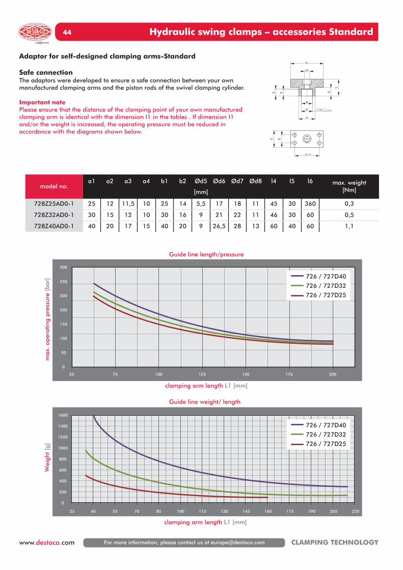
1600
1400
1200
1000
800
600
400
200
0
300
250
200
200
150
100
50
0
4025 55 70 85 100 115 130 145 160 175 190 205 220
clamping arm length L1 [mm]
Guide line length/pressure
Guide line weight/ length
clamping arm length L1 [mm]
Wei
ght
[g]
max
. op
erat
ing
pres
sure
[ba
r] 726 / 727D40
726 / 727D32
726 / 727D25
25 75 100 125 150 175 200
726 / 727D40
726 / 727D32
726 / 727D25
model no.a1 a2 a3 a4 b1 b2 Ød5
[mm]
Ød6 Ød7 Ød8 l4 l5 l6 max. weight[Nm]
728Z25AD0-1 25 12 11,5 10 25 14 5,5 17 18 11 45 30 360 0,3
728Z32AD0-1 30 15 12 10 30 16 9 21 22 11 46 30 60 0,5
728Z40AD0-1 40 20 17 15 40 20 9 26,5 28 13 60 40 60 1,1
d8
d6
d7 1:10
a4a3
l6
a2
a1
l5
l4 ±0,1
b1 b2
Adaptor for self-designed clamping arms-Standard
Safe connectionThe adaptors were developed to ensure a safe connection between your ownmanufactured clamping arms and the piston rods of the swivel clamping cylinder.
Important notePlease ensure that the distance of the clamping point of your own manufacturedclamping arm is identical with the dimension I1 in the tables . If dimension I1and/or the weight is increased, the operating pressure must be reduced in accordance with the diagrams shown below.
Hydraulic swing clamps – accessories compact 45
For more information, please contact us at [email protected] www.destaco.comCLAMPING TECHNOLOGY
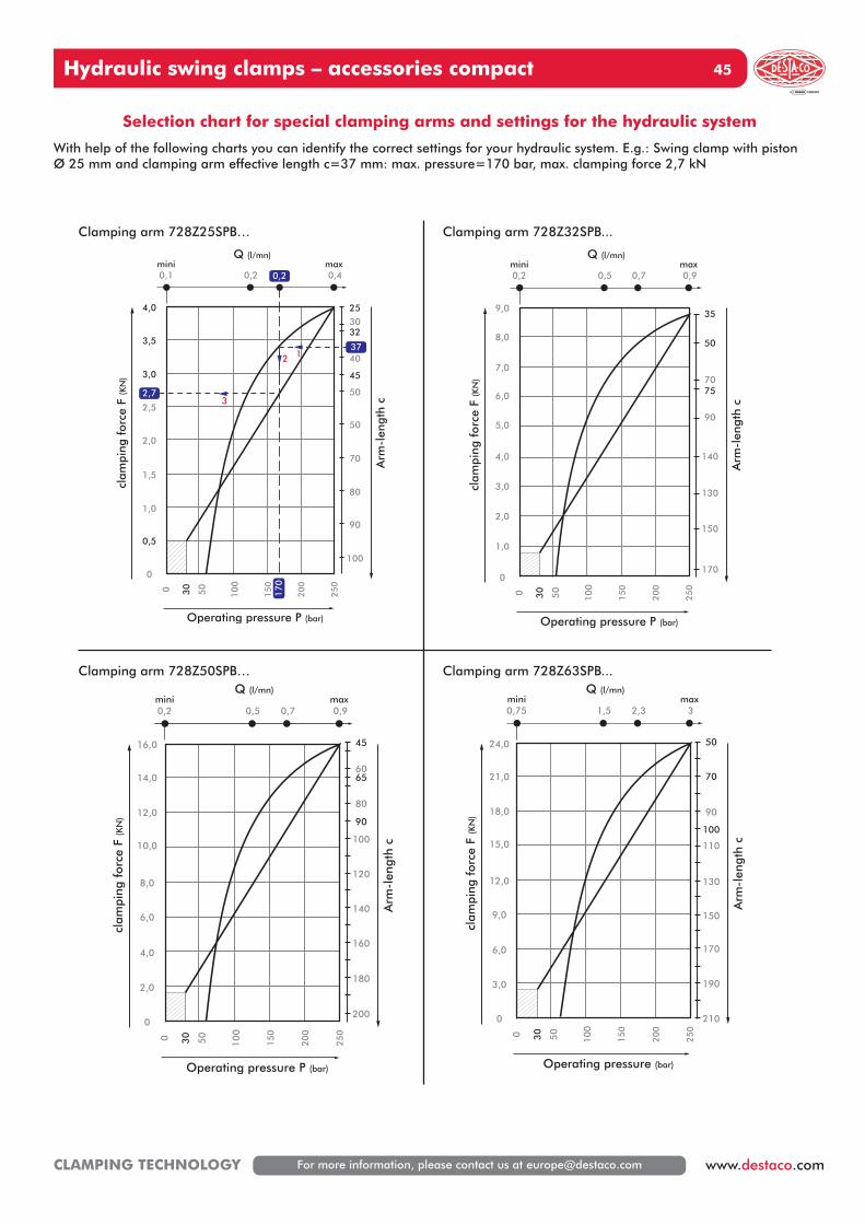
Selection chart for special clamping arms and settings for the hydraulic system
With help of the following charts you can identify the correct settings for your hydraulic system. E.g.: Swing clamp with piston Ø 25 mm and clamping arm effective length c=37 mm: max. pressure=170 bar, max. clamping force 2,7 kN
100
0,5
0
0 30
50
100
150
200
250
clam
ping
for
ce F
(KN
)
Arm
-len
gth
c
Q (l/mn)
Operating pressure P (bar)
1,0
1,5
2,0
2,5
3,0
3,5
4,0
0,1mini max
0,2
12
3
0,4
90
80
70
50
50
40
45
3032
25
0,2
37
2,7
170
170
1,0
0
0 30
50
100
150
200
250
clam
ping
for
ce F
(KN
)
Q (l/mn)
2,0
3,0
5,0
4,0
6,0
7,0
8,0
9,0
0,2mini max
0,5 0,7 0,9
150
130
140
90
7570
50
35
Arm
-len
gth
c
Operating pressure P (bar)
200
2,0
0
0 30
50
100
150
200
250
clam
ping
for
ce F
(KN
)
Q (l/mn)
4,0
8,0
6,0
10,0
12,0
14,0
16,0
0,2mini max
0,5 0,7 0,9
180
160
120
140
100
80
90
6560
45
Arm
-len
gth
c
Operating pressure P (bar)
210
3,0
0
0 30
50
100
150
200
250
clam
ping
for
ce F
(KN
)
Q (l/mn)
6,0
12,0
9,0
15,0
18,0
21,0
24,0
0,75mini max
1,5 2,3 3
190
170
130
150
100
110
90
70
50A
rm-l
engt
h c
Operating pressure (bar)
Clamping arm 728Z25SPB… Clamping arm 728Z32SPB...
Clamping arm 728Z50SPB… Clamping arm 728Z63SPB...
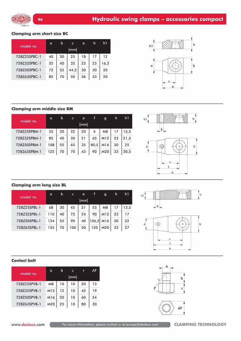
Hydraulic swing clamps – accessories compact46
For more information, please contact us at [email protected] CLAMPING TECHNOLOGY
hh1
a
c
be
h1 h
g
a
b
c
f
e
hh1
g
a
b
c
f
e
c
b
a
r
AF
Clamping arm short size BC
Clamping arm middle size BM
Clamping arm long size BL
Contact bolt
model no.a b c
[mm]
e h h1
728Z25SPBC-1 40 30 25 18 17 12
728Z32SPBC-1 55 40 35 23 23 16,5
728Z50SPBC-1 72 55 44,5 30 30 20
728Z63SPBC-1 85 70 50 36 33 20
model no.a b c e
[mm]
f g h h1
728Z25SPBM-1 55 30 32 20 4 M8 17 15,5
728Z32SPBM-1 85 40 50 21 65 M12 23 21,5
728Z50SPBM-1 108 55 65 35 80,5 M16 30 25
728Z63SPBM-1 125 70 70 43 90 M20 33 30,5
model no.a b c e
[mm]
f g h h1
728Z25SPBL-1 68 30 45 21 53 M8 17 13,5
728Z32SPBL-1 110 40 75 24 90 M12 23 17
728Z50SPBL-1 134 55 90 40 106,5 M16 30 22
728Z63SPBL-1 155 70 100 50 120 M20 33 27
model no.a b c
[mm]
r AF
728Z25SPVB-1 M8 10 10 20 13
728Z32SPVB-1 M12 12 10 45 19
728Z50SPVB-1 M16 20 10 60 24
728Z63SPVB-1 M20 25 10 80 30
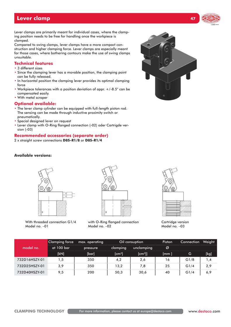
Lever clamp 47
For more information, please contact us at [email protected] www.destaco.comCLAMPING TECHNOLOGY
With threaded connection G1/4Model no. –01
with O-Ring flanged connectionModel no. –02
Cartridge versionModel no. –03
Lever clamps are primarily meant for individual cases, where the clamp-ing position needs to be free for handling once the workpiece isclamped.Compared to swing clamps, lever clamps have a more compact con-struction and higher clamping force. Lever clamps are especially meantfor those cases, where bothering contours make the use of swing clampsunsuitable.
Technical features• 3 different sizes• Since the clamping lever has a movable position, the clamping point
can be fully released.• In horizontal position the clamping lever provides its optimal clamping
force• Workpiece tolerances with a position deviation of appr. +/-8.5° can be
compensated easily.• With metal scraper
Optional available:• The lever clamp cylinder can be equipped with full-length piston rod.
The sensing can be made through inductive proximity switch or pneumatically.
• Special designed lever on request• Lever clamp with O-Ring flanged connection (-02) oder Cartrigde ver-
sion (-03)
Recommended accessories (separate order)2 x straight screw connections D8S-R1/8 or D8S-R1/4
model no.
Clamping force max. operating Oil consuption Piston Connection Weight
at 100 bar pressure clamping unclamping Ø
[kN] [bar] [cm³] [cm³]] [mm ] G [kg]
732D16HSZY-01 1,5 350 4,2 2,6 16 G1/8 1,4
732D25HSZY-01 3,9 350 13,2 7,8 25 G1/4 2,9
732D40HSZY-01 9,5 200 50,3 30,6 40 G1/4 6,9
Available versions:
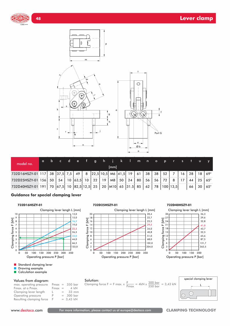
Lever clamp48
For more information, please contact us at [email protected] CLAMPING TECHNOLOGY
Operating pressure P [bar]Operating pressure P [bar]
� Standard clamping lever� Drawing example� Calculation example
00
1
2
3
4
5
6
7
8
9
10
0
2
4
68
10
12
14
16
18
20
0
3
6
912
15
18
21
24
27
30 26,3
29,6
32,8
41,043,752,5
65,687,5
131,7
262,5
20,4
22,7
25,5
29,5
34,040,8
51,068,0
102,0
204,0
13,0
15,0
16,5
19,0
22,526,5
33,044,0
66,5
133,0
50 100 150 200 250 300 350 0 50 100 150 200 250 300 350 0 50 100 150 200
Operating pressure P [bar]
Cla
mpi
ng f
orce
F [
kN]
Cla
mpi
ng f
orce
F [
kN]
Cla
mpi
ng f
orce
F [
kN]
Clamping lever lengh L [mm]Clamping lever lengh L [mm]
732D16HSZY-01 732D25HSZY-01 732D40HSZY-01
Clamping lever lengh L [mm]
Values from diagram:max. operating pressure Pmax = 350 barFmax. at a Pmax. Fmax = 4 kNClamping lever length L = 33 mmOperating pressure P = 300 barResulting clamping force F = 3,43 kN
Clamping force F = F max. x 300 bar350 bar
PPmax
= 4kN x = 3,43 kNSolution:
e
l
c
k
d
g
h
n
Port Gjr
y
Ø b
a
u
f
o
t
p
m
s
Guidance for special clamping lever
model no.a b c d e f g h j
[mm]
k l m n o p r s t u y
732D16HSZY-01 117 38 37,5 7,5 49 8 22,5 10,5 M6 41,5 19 61 38 38 52 7 16 28 18 69°
732D25HSZY-01 156 50 54 10 63,5 10 22 19 M8 50 24 80 56 56 72 8 17 44 25 65°
732D40HSZY-01 191 70 67,5 10 82,5 12,5 25 20 M10 65 31.5 85 62 78 100 13,5 66 30 65°
special clamping lever
L
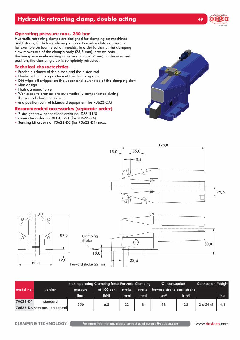
Hydraulic retracting clamp, double acting 49
For more information, please contact us at [email protected] www.destaco.comCLAMPING TECHNOLOGY
model no. version
max. operating Clamping force Forward Clamping Oil consuption Connection Weight
pressure at 100 bar stroke stroke forward stroke back stroke
[bar] [kN] [mm] [mm] [cm³] [cm³] [kg]
70622-D1 standard250 6,5 22 8 38 23 2 x G1/8 4,1
70622-DA with position control
80,0
89,0
12,0Forward stroke 22mm
23, 5
10,0
Clampingstroke
8mm
190,0
15,0 35,0
8,5
60,0
25,5
Operating pressure max. 250 barHydraulic retracting clamps are designed for clamping on machinesand fixtures, for holding-down plates or to work as latch clamps asfor example on foam ejection moulds. In order to clamp, the clampingclaw moves out of the clamp’s body (23,5 mm), presses ontothe workpiece while moving downwards (max. 9 mm). In the releasedposition, the clamping claw is completely retracted.
Technical characteristics• Precise guidance of the piston and the piston rod• Hardened clamping surface of the clamping claw• Dirt wipe-off stripper on the upper and lower side of the clamping claw• Slim design• High clamping force• Workpiece tolerances are automatically compensated during
the vertical clamping stroke• end position control (standard equipment for 70622-DA)
Recommended accessories (separate order)• 2 straight srew connections order no. D8S-R1/8• connector order no. 8EL-002-1 (for 70622-DA)• Sensing kit order no. 70622-DE (for 70622-D1) max.
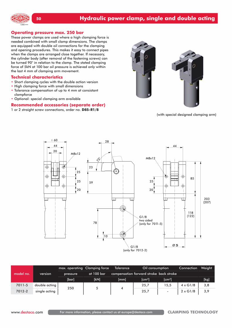
Hydraulic power clamp, single and double acting50
For more information, please contact us at [email protected] CLAMPING TECHNOLOGY
model no. version
max. operating Clamping force Tolerance Oil consumption Connection Weight
pressure at 100 bar compensation forward stroke back stroke
[bar] [kN] [mm] [cm³] [cm³] [kg]
7011-5 double acting250 5 4
25,7 15,5 4 x G1/8 3,8
7012-2 single acting 25,7 - 2 x G1/8 3,9
23
28
59
75°
10
78
G1/8(only for 7012-2)
G1/8two sided(only for 7011-5)
203(207)
85
118(122)
44
20
25
Ø 55
M8x12
60
20
44
20
25
25
M8x12
Operating pressure max. 250 barThese power clamps are used where a high clamping force isneeded combined with small clamp dimensions. The clampsare equipped with double oil connections for the clampingand opening procedures. This makes it easy to connect pipeswhen the clamps are arranged close together. If necessary,the cylinder body (after removal of the fastening screws) canbe turned 90° in relation to the clamp. The stated clampingforce of 5kN at 100 bar oil pressure is achieved only withinthe last 4 mm of clamping arm movement.
Technical characteristics• Short clamping cycles with the double action version• High clamping force with small dimensions• Tolerance compensation of up to 4 mm at consistant
clampforce• Optional: special clamping arm available
Recommended accessories (separate order)1 or 2 straight screw connections, order no. D8S-R1/8
(with special designed clamping arm)
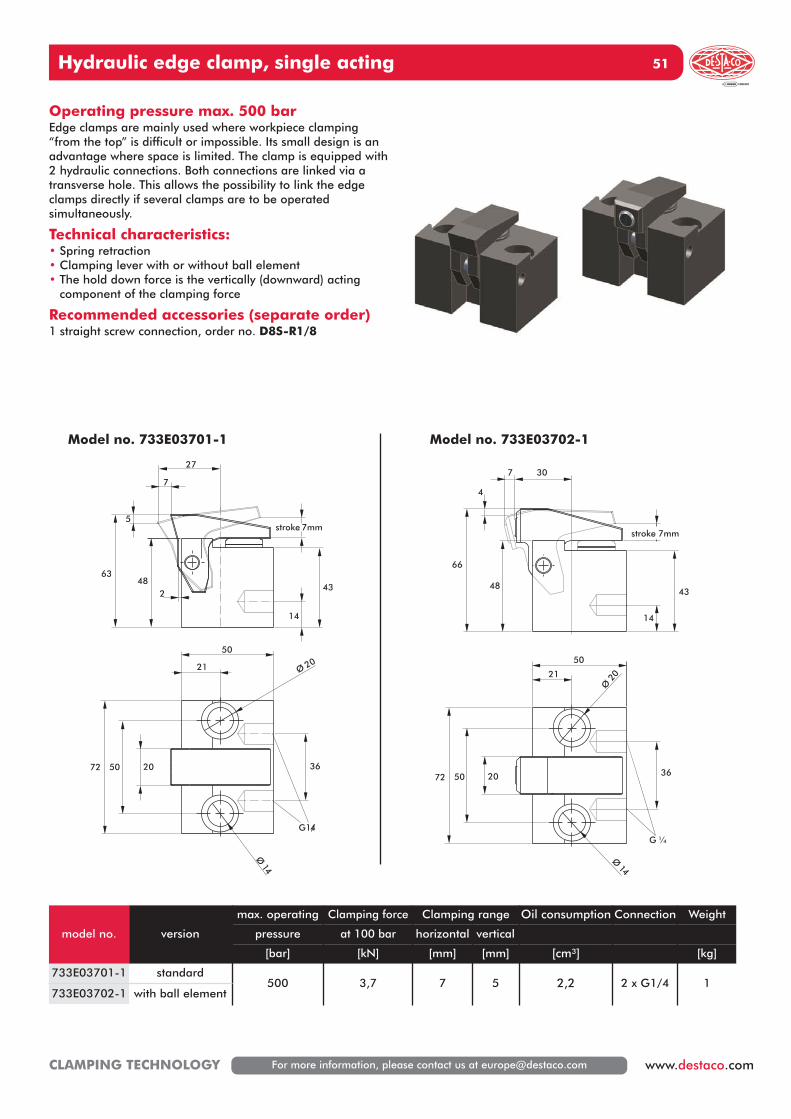
Hydraulic edge clamp, single acting 51
For more information, please contact us at [email protected] www.destaco.comCLAMPING TECHNOLOGY
model no. version
max. operating Clamping force Clamping range Oil consumption Connection Weight
pressure at 100 bar horizontal vertical
[bar] [kN] [mm] [mm] [cm³] [kg]
733E03701-1 standard500 3,7 7 5 2,2 2 x G1/4 1
733E03702-1 with ball element
14
7
5
4843
stroke 7mm
63
2
36
Ø 20
Ø14
205072
21
50
G1/4
27
Operating pressure max. 500 barEdge clamps are mainly used where workpiece clamping“from the top” is difficult or impossible. Its small design is anadvantage where space is limited. The clamp is equipped with2 hydraulic connections. Both connections are linked via atransverse hole. This allows the possibility to link the edgeclamps directly if several clamps are to be operated simultaneously.
Technical characteristics:• Spring retraction• Clamping lever with or without ball element• The hold down force is the vertically (downward) acting
component of the clamping force
Recommended accessories (separate order)1 straight screw connection, order no. D8S-R1/8
Model no. 733E03701-1
7 30
14
4843
stroke 7mm
66
4
G ¼
Ø20
Ø14
5072 20
21
50
36
Model no. 733E03702-1
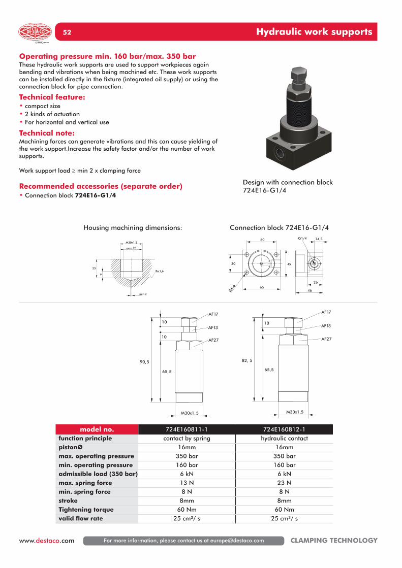
Hydraulic work supports52
For more information, please contact us at [email protected] CLAMPING TECHNOLOGY
50
45
65
30
Ø6,
6
26
46
14,5G1/4
82, 5
65,5
10
M30x1,5
AF17
AF13
AF27
90,5
10
65,5
M30x1,5
10
AF17
AF27
AF13
max. 20
M30x1.5
9
25
min 2
Ra 1,6
model no. 724E160811-1 724E160812-1function principle contact by spring hydraulic contactpistonØ 16mm 16mmmax. operating pressure 350 bar 350 barmin. operating pressure 160 bar 160 baradmissible load (350 bar) 6 kN 6 kNmax. spring force 13 N 23 Nmin. spring force 8 N 8 Nstroke 8mm 8mmTightening torque 60 Nm 60 Nmvalid flow rate 25 cm³/ s 25 cm³/ s
Operating pressure min. 160 bar/max. 350 barThese hydraulic work supports are used to support workpieces againbending and vibrations when being machined etc. These work supportscan be installed directly in the fixture (integrated oil supply) or using theconnection block for pipe connection.
Technical feature:• compact size• 2 kinds of actuation• For horizontal and vertical use
Technical note:Machining forces can generate vibrations and this can cause yielding ofthe work support.Increase the safety factor and/or the number of worksupports.
Work support load � min 2 x clamping force
Recommended accessories (separate order)• Connection block 724E16-G1/4
Connection block 724E16-G1/4Housing machining dimensions:
Design with connection block724E16-G1/4
Hydraulic work supports 53
For more information, please contact us at [email protected] www.destaco.comCLAMPING TECHNOLOGY
p
b
D
c
a
l
ku u
f
r
eAF
g
Operating pressure min. 150 bar/max. 300 barThese hydraulic work supports are used to support workpieces againbending and vibrations when being machined etc. The work supportautomatically adjusts to the contour of the workpiece and support theworkpiece in position. This support adds rigidity to the fixturedcomponent to minimize machining variations.
Technical features:• 3 sizes with base flange• With additional venting port• For horizontal and vertical use• Manifold mounting version (with O-Ring) available on request
Technical note:Machining forces can generate vibrations and this can cause yielding ofthe work support.Increase the safety factor and/or the number of worksupports.
Work support load � min 2 x clamping force
• Do not exceed maximum flow rates of 1,5 l/min to avoid prematurelockup
• Always center load over work support.
Recommended accessories (separate order)• 1 straight screw connection D8S-R1/4
model no.Locking force
at 150 bar at 300 bar[kN] [kN]
StrokePiston
ØD a b c e
LK[mm]
g k l p r u
724E201232-1 2,8 7 12 20 42 28 20 84 67 54 M12x15 G1/4 12 7 42 30°
724E301232-1 4,7 12,5 12 30 54 32 22 82 79 66 M12x18 G1/4 12 7 54 30°
724E401632-1 7 22 16 40 67 40 28 110 98 82 M16x16 G1/4 12 9 67 35°
Hydraulic work supports54
For more information, please contact us at [email protected] CLAMPING TECHNOLOGY
D
cn
mp
k
ba
l
u u
f e
r
AF
g
Operating pressure min. 150 bar/max. 300 barThese hydraulic work supports are used to support workpieces againbending and vibrations when being machined etc. The work supportautomatically adjusts to the contour of the workpiece and support theworkpiece in position. This support adds rigidity to the fixturedcomponent to minimize machining variations.
Technical features:• 3 sizes with top flange• With additional venting port• For horizontal and vertical use• Manifold version (with O-Ring sealing, Cartridge version)
available on request
Technical note:Machining forces can generate vibrations and this can cause yieldingof the work support.Increase the safety factor and/or the number ofwork supports.
Work support load � min 2 x clamping force
• Do not exceed maximum flow rates of 1,5 l/min to avoidpremature lockup
• Always center load over work support.
Recommended accessories (separate order)• 1 straight screw connection D8S-R1/8 or• 1 straight screw connection D8S-R1/4
model no.Locking force
at 150 bar at 300 bar[kN] [kN]
StrokePiston
ØD a b c e
LK[mm]
g k l m n p r u
724E201242-1 2,8 7 12 20 42 28 20 84 67 54 M12x15 G1/8 9 11 6,5 7 42 30°
724E301242-1 4,7 12,5 12 30 54 32 22 82 79 66 M12x18 G1/8 9 11 6,5 7 54 30°
724E401642-1 7 22 16 40 67 40 28 110 98 82 M16x16 G1/4 12 14 9 9 67 35°
Pressure accumulator control unit, double action 55
For more information, please contact us at [email protected] www.destaco.comCLAMPING TECHNOLOGY
191
175
accumulator13cm³
pressure relief valvep max 400 bar
6034
102
P2 P1
P1P Y A BAir-hydraulic-pumps713D15058-1(up to 150 bar)713D36058-1(up to 360 bar)713D60058-1(up to 600 bar)
quickdisconnect
P2 P1
Y1
quickdisconnect
761D40001-113cm³
Pressure accumulator control unit, double actionOperating pressure max. 400 barThe pressure accumulator control unit is used in those applicationswhere hydraulic clamping devices are disconnected from thepressure generators, e.g. on flexible production systems withhydraulic clamping devices, CNC machine tools in conjunction withpalette exchangers.The main task of the pressure accumulator control unit is tocompensate for pressure fluctuations and in the event of any minorleakages to prevent sudden drops in pressure.Control is effected only via the air hydraulic pump. Switchover isautomatically controlled by an internal back pressure valve insidethe pressure control unit which avoids the necessity to fit anadditional manual valve.The protection for the pressure control unit is guaranteed by theintegrated pressure relief valve.
Model no.max. operating
pressure[bar]
Pressure reliefvalve set at
[bar]
Gas pressure[bar]
Accumulator volume[bar]
ConnectionWeight
[kg]
761D40001-1 400 400 100 13 G1/4 5,4
Hydraulic rotary unions56
For more information, please contact us at [email protected] CLAMPING TECHNOLOGY
Pressure [bar]
50 100 150 200 250 300 350 400
14
12
10
8
6
4
2
0
Torq
ue [
Nm
]
Starting torque70-DR20 70-DR40 70-DR60
Pressure [bar]
50 100 150 200 250 300 350 400
9080706050403020100
Rota
tions
[1
/min
]
Admissible numbers of rotation70-DR20 70-DR40 70-DR60
Operation pressure max. 400 barRotary unios transfer hydraulic oil from a fixed to a rotatingmachine part. The assembly is done in the rotating axis of thesubassembly. Depending on the number of junction levels severalsingle or double acting hydraulic elements can be connected.On principle, the rotary coupling is only suitable for hydraulic oil.If pneumatic shall be transferred, the catalogued elements can beused providing that the air is filtered and lubricated to guaranteeseal greasing and corrosion protection.
Technical features:• 2 versions per size• Suitable for hydraulic, pneumatic and vacuum
Optional:• Rotary valve unions
model no. nominaldiameter
ConnectionsRotations*
1/min
Leakage rate
cm³/ 100h
Connectionstandard
ports
Connectionleakage port
Weight
[kg]
70-DR20-1 5 2 50-80 0 G1/4 - 2,2
70-DR20-2 5 2 50-80 30 G1/4 G1/8 2,5
70-DR40-1 5 4 25-45 0 G1/4 - 3,8
70-DR40-2 5 4 25-45 50 G1/4 G1/8 4,2
70-DR60-1 5 6 25-35 0 G1/4 - 5,8
70-DR60-2 5 6 25-35 60 G1/4 G1/8 6,2
*pressure-controlled
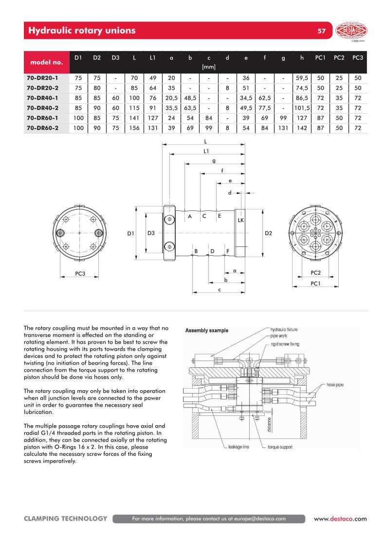
Hydraulic rotary unions 57
For more information, please contact us at [email protected] www.destaco.comCLAMPING TECHNOLOGY
L1
D2D3D1
a
b
c
d
e
f
g
L
C E
FDB
LKA
PC2
PC1
PC3
model no.D1 D2 D3 L L1 a b c
[mm]
d e f g h PC1 PC2 PC3
70-DR20-1 75 75 - 70 49 20 - - - 36 - - 59,5 50 25 50
70-DR20-2 75 80 - 85 64 35 - - 8 51 - - 74,5 50 25 50
70-DR40-1 85 85 60 100 76 20,5 48,5 - - 34,5 62,5 - 86,5 72 35 72
70-DR40-2 85 90 60 115 91 35,5 63,5 - 8 49,5 77,5 - 101,5 72 35 72
70-DR60-1 100 85 75 141 127 24 54 84 - 39 69 99 127 87 50 72
70-DR60-2 100 90 75 156 131 39 69 99 8 54 84 131 142 87 50 72
The rotary coupling must be mounted in a way that notransverse moment is effected on the standing orrotating element. It has proven to be best to screw therotating housing with its ports towards the clampingdevices and to protect the rotating piston only againsttwisting (no initiation of bearing forces). The lineconnection from the torque support to the rotatingpiston should be done via hoses only.
The rotary coupling may only be taken into operationwhen all junction levels are connected to the powerunit in order to guarantee the necessary seallubrication.
The multiple passage rotary couplings have axial andradial G1/4 threaded ports in the rotating piston. Inaddition, they can be connected axially at the rotatingpiston with O-Rings 16 x 2. In this case, pleasecalculate the necessary screw forces of the fixingscrews imperatively.
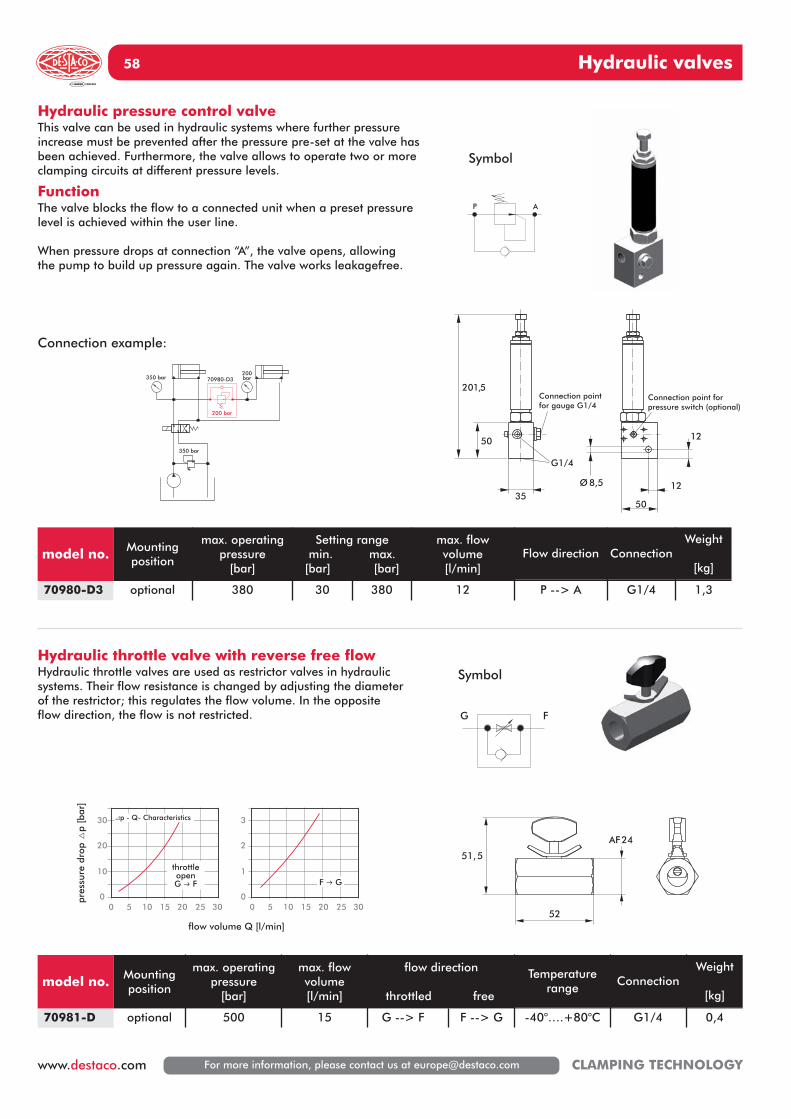
Hydraulic valves58
For more information, please contact us at [email protected] CLAMPING TECHNOLOGY
50
Ø 8,5
12
12
Connection point forpressure switch (optional)
201,5
35
50
Connection pointfor gauge G1/4
G1/4
51,5
52
AF24
00
10
20
30
5 10 15
flow volume Q [l/min]
pres
sure
dro
p △
p [b
ar]
20 25 30 00
1
2
3
5 10 15 20 25 30
�p - Q- Characteristics
throttleopenG � F F � G
350 bar
350 bar200bar
200 bar
70980-D3
AP
G F
Hydraulic pressure control valveThis valve can be used in hydraulic systems where further pressureincrease must be prevented after the pressure pre-set at the valve hasbeen achieved. Furthermore, the valve allows to operate two or moreclamping circuits at different pressure levels.
Function The valve blocks the flow to a connected unit when a preset pressurelevel is achieved within the user line.
When pressure drops at connection “A”, the valve opens, allowingthe pump to build up pressure again. The valve works leakagefree.
Hydraulic throttle valve with reverse free flowHydraulic throttle valves are used as restrictor valves in hydraulicsystems. Their flow resistance is changed by adjusting the diameterof the restrictor; this regulates the flow volume. In the oppositeflow direction, the flow is not restricted.
Connection example:
Symbol
Symbol
model no. Mounting position
max. operatingpressure
[bar]
Setting rangemin. max.
[bar] [bar]
max. flow volume[l/min]
Flow direction ConnectionWeight
[kg]
70980-D3 optional 380 30 380 12 P --> A G1/4 1,3
model no. Mountingposition
max. operatingpressure
[bar]
max. flow volume[l/min]
flow direction
throttled free
Temperaturerange
ConnectionWeight
[kg]
70981-D optional 500 15 G --> F F --> G -40°….+80°C G1/4 0,4
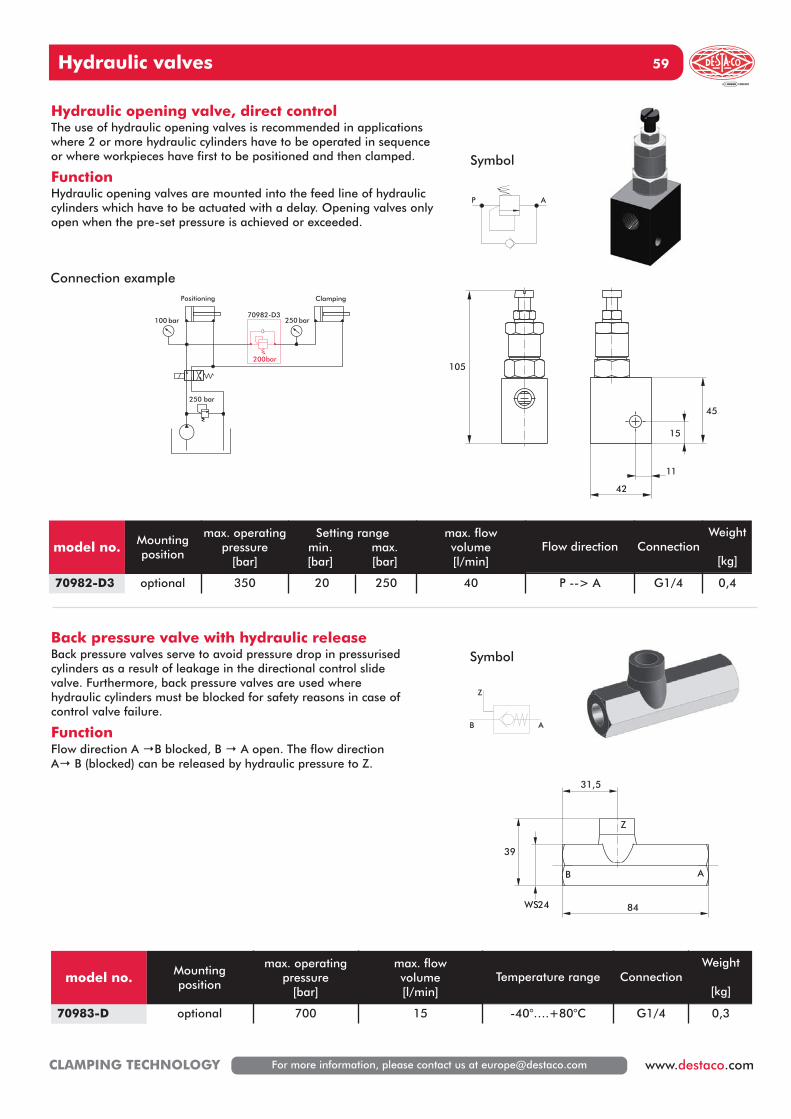
Hydraulic valves 59
For more information, please contact us at [email protected] www.destaco.comCLAMPING TECHNOLOGY
105
42
11
15
45
AB
Z
84WS24
39
31,5
250 bar
100 bar 250 bar
200bar
70982-D3
Positioning Clamping
P A
B A
Z
Connection example
Symbol
Hydraulic opening valve, direct controlThe use of hydraulic opening valves is recommended in applicationswhere 2 or more hydraulic cylinders have to be operated in sequenceor where workpieces have first to be positioned and then clamped.
FunctionHydraulic opening valves are mounted into the feed line of hydrauliccylinders which have to be actuated with a delay. Opening valves onlyopen when the pre-set pressure is achieved or exceeded.
Back pressure valve with hydraulic releaseBack pressure valves serve to avoid pressure drop in pressurisedcylinders as a result of leakage in the directional control slidevalve. Furthermore, back pressure valves are used wherehydraulic cylinders must be blocked for safety reasons in case ofcontrol valve failure.
FunctionFlow direction A →B blocked, B → A open. The flow directionA→ B (blocked) can be released by hydraulic pressure to Z.
Symbol
model no. Mountingposition
max. operatingpressure
[bar]
Setting rangemin. max.[bar] [bar]
max. flow volume[l/min]
Flow direction ConnectionWeight
[kg]
70982-D3 optional 350 20 250 40 P --> A G1/4 0,4
model no. Mountingposition
max. operatingpressure
[bar]
max. flow volume[l/min]
Temperature range ConnectionWeight
[kg]
70983-D optional 700 15 -40°….+80°C G1/4 0,3
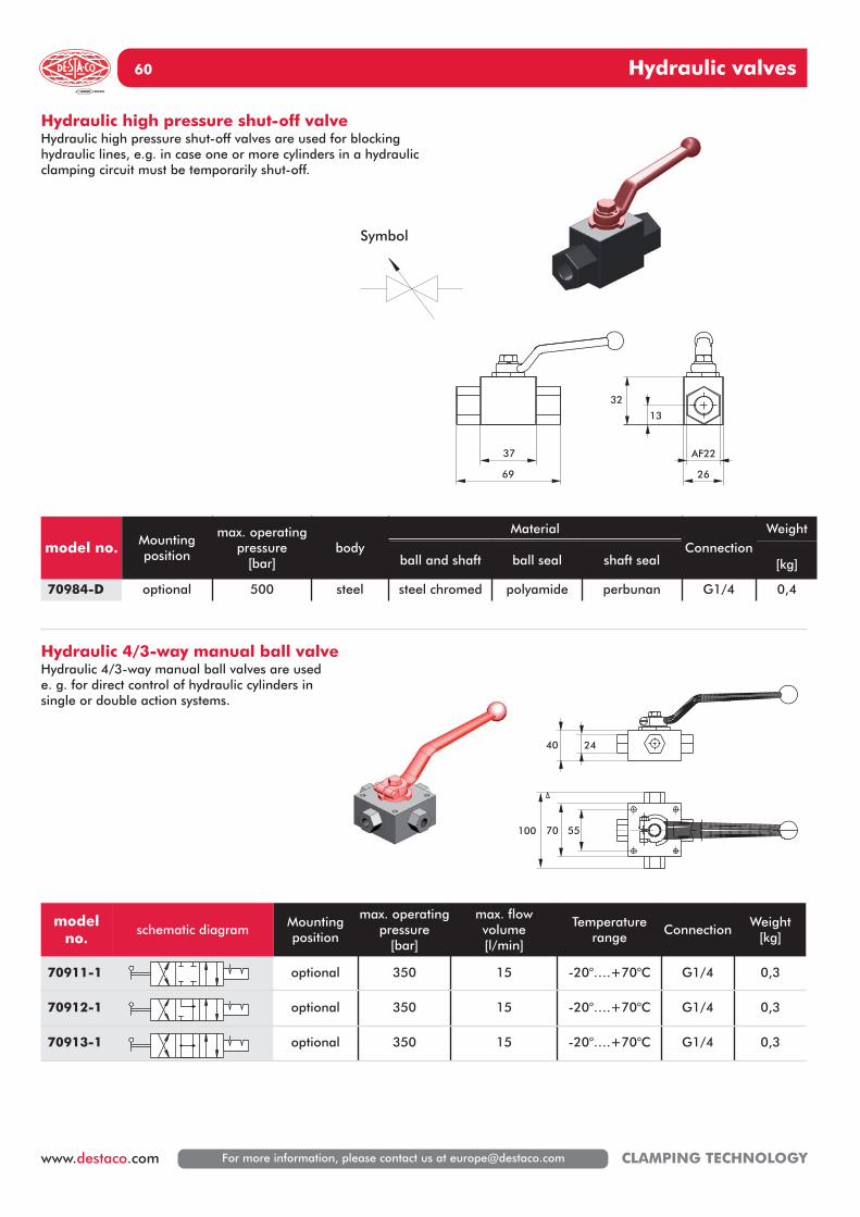
Hydraulic valves60
For more information, please contact us at [email protected] CLAMPING TECHNOLOGY
70 55100
2440
69
37
26
AF22
32
13
Hydraulic high pressure shut-off valveHydraulic high pressure shut-off valves are used for blockinghydraulic lines, e.g. in case one or more cylinders in a hydraulicclamping circuit must be temporarily shut-off.
Hydraulic 4/3-way manual ball valveHydraulic 4/3-way manual ball valves are used e. g. for direct control of hydraulic cylinders insingle or double action systems.
Symbol
model no. Mountingposition
max. operatingpressure
[bar]body
MaterialConnection
Weight
ball and shaft ball seal shaft seal [kg]
70984-D optional 500 steel steel chromed polyamide perbunan G1/4 0,4
modelno.
schematic diagramMountingposition
max. operatingpressure
[bar]
max. flow volume[l/min]
Temperaturerange
ConnectionWeight
[kg]
70911-1 optional 350 15 -20°….+70°C G1/4 0,3
70912-1 optional 350 15 -20°….+70°C G1/4 0,3
70913-1 optional 350 15 -20°….+70°C G1/4 0,3
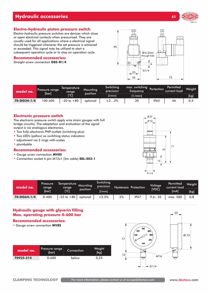
Hydraulic accessories 61
For more information, please contact us at [email protected] www.destaco.comCLAMPING TECHNOLOGY
73
25
35
6
95
G1/4
Ø 6,3mmthrough hole
12
G 1/4
6271
Ø 12
Ø 27
12
77
G1/4
AF14
Ø 73
32
Electro-hydraulic piston pressure switchElectro-hydraulic pressure switches are devices which closeor open electrical contacts when pressurized. They areusually used for all applications where a electrical signalshould be triggered whenever the set pressure is achievedor exceeded. This signal may be utilized to start asubsequent operation cycle or to stop an operation cycle.
Recommended accessories:Straight screw connection D8S-R1/4
model no. Pressure range[bar]
Temperaturerange[°C]
Mountingposition
Switchingprecision
max. switchingfrequency
PortectionPermitted
current loadWeight
[l/min] [1/min] [kg]
70-DG34-1/4 100-400 -20 to +80 optional ±2…3% 30 IP65 4A 0,4
model no.Pressurerange[bar]
Temperaturerange[°C]
Mountingposition
Switchingprecision Hysteresis Protection
Voltage[VDC]
Permittedcurrent load
[mA]
Weight
[l/min] [kg]
70-DG64-1/4 0-400 -25 to +80 optional ±2,5% 2% IP67 9,6...32 max. 500 0,8
Electronic pressure switchThe electronic pressure switch apply wire strain gauges with fullbridge circuitry. The adaptation and evaluation of the signaloutput is via analogous electronics.• Two fully-electronic PNP-outlets (switching plus)• Two LED's (yellow) as switching status indicators• adjustment via 2 rings with scales• plombable
Recommended accessories:• Gauge screw connection MV8S• Connection socket 4-pin M12x1 (5m cable) 8EL-003-1
Hydraulic gauge with glycerin fillingMax. operating pressure 0-600 bar
Recommended accessories:• Gauge screw connection MV8S
model no. Pressure range[bar]
ConnectionWeight
[kg]
70925-214 0-600 below 0,25
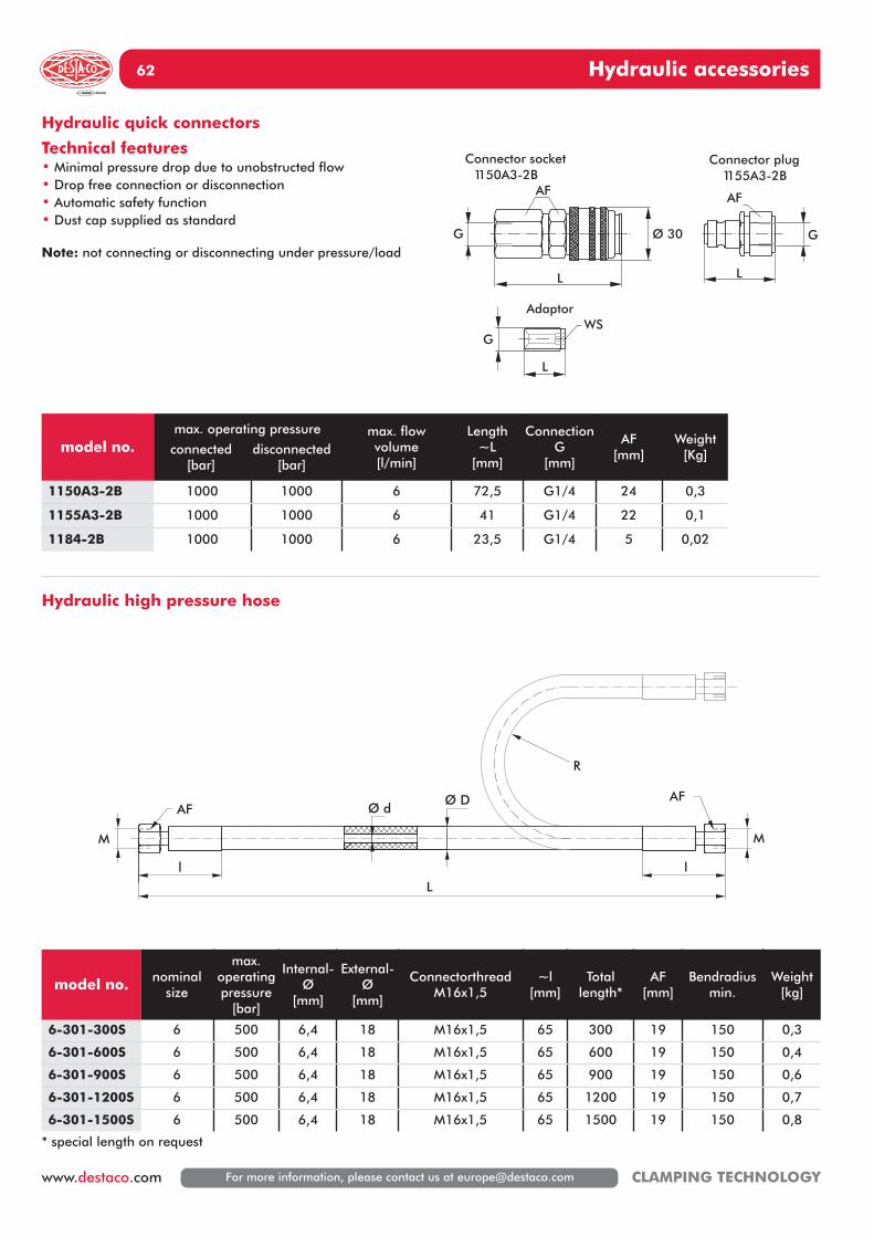
Hydraulic accessories62
For more information, please contact us at [email protected] CLAMPING TECHNOLOGY
L
G
G G
LL
AF AF
Ø 30
WS
Connector socket1150A3-2B
Connector plug1155A3-2B
Adaptor
R
Ø dØ D
l
M
AF
lL
M
AF
model no.max. operating pressure
connected disconnected[bar] [bar]
max. flowvolume[l/min]
Length~L
[mm]
Connection G
[mm]
AF[mm]
Weight[Kg]
1150A3-2B 1000 1000 6 72,5 G1/4 24 0,3
1155A3-2B 1000 1000 6 41 G1/4 22 0,1
1184-2B 1000 1000 6 23,5 G1/4 5 0,02
Hydraulic quick connectors
Technical features• Minimal pressure drop due to unobstructed flow• Drop free connection or disconnection• Automatic safety function• Dust cap supplied as standard
Note: not connecting or disconnecting under pressure/load
model no. nominalsize
max. operatingpressure
[bar]
Internal-Ø
[mm]
External-Ø
[mm]
ConnectorthreadM16x1,5
~l[mm]
Totallength*
AF[mm]
Bendradiusmin.
Weight[kg]
6-301-300S 6 500 6,4 18 M16x1,5 65 300 19 150 0,3
6-301-600S 6 500 6,4 18 M16x1,5 65 600 19 150 0,4
6-301-900S 6 500 6,4 18 M16x1,5 65 900 19 150 0,6
6-301-1200S 6 500 6,4 18 M16x1,5 65 1200 19 150 0,7
6-301-1500S 6 500 6,4 18 M16x1,5 65 1500 19 150 0,8
Hydraulic high pressure hose
* special length on request
Hydraulic accessories 63
For more information, please contact us at [email protected] www.destaco.comCLAMPING TECHNOLOGY
model no.max. pressure ~L M AF1 AF2 Thread
[bar] [mm] GD8L-R1/8 200 31 M14x1,5 17 17 G1/8D8L-R1/4 250 36,5 M14x1,5 19 17 G1/8D8L-SAE4 250 36,5 M14x1,5 19 17 7/16-20UNFD8S-R1/8 630 39 M16x1,5 17 19 G1/4D8S-R1/4 630 42 M16x1,5 19 19 G1/4
D8L-1/8NPT 200 31,5 M14x1,5 14 17 1/8NPTD8L-1/4NPT 250 36,5 M14x1,5 14 17 1/4NPTD8S-1/4NPT 630 42,5 M16x1,5 17 19 1/4NPT
model no.max. pressure H ~h M AF1 AF2 Thread
[bar] [mm] GDSVK-8LR 250 45 29 M14x1,5 17 22 G1/4DSVK-8SR 630 45 31 M16x1,5 19 22 G1/4
Straight screw connection
Screw connections for hydraulic pipe (external Ø 8mm) and hydraulic hoses
L-screw connection, adjustable
H
G
M
h
AF1
AF2
G
LM
AF1 AF2
L-screw connection
M
h
h
AF2
AF1
T-screw connection
h
L
M
M
AF2AF1
Screw connection, standard application (coupling nut M14x1,5 or M16x1,5 and cutting ring are removable)
Permittet operating pressure• L-screw connection R1/8 max. 200 bar (e.g. D8L-R1/8)• L-screw connection R1/4 max. 250 bar (e.g. D8L-R1/4)• S-screw connection max. 630 bar (e.g. D8S-R1/4)
model no.max. pressure ~h M AF1 AF2
[bar] [mm]K8L 250 29 M14x1,5 17 12K8S 630 31 M16x1,5 19 14
model no.max. pressure ~h ~L M AF1 AF2
[bar] [mm]Q8L 250 29 57 M14x1,5 17 12Q8S 630 31 63 M16x1,5 19 14
Hydraulic accessories64
For more information, please contact us at [email protected] CLAMPING TECHNOLOGY
model no.max. pressure ~H M AF1 AF2
[bar] [mm]KV8L 250 57 M14x1,5 17 12KV8S 630 63 M16x1,5 19 14
Cross screw connection
H
H
M
AF2
AF1
model no.max. pressure ~H M Thread AF1
[bar] [mm] GKV8L MV8L 250 34 M14x1,5 17KV8S MV8S 630 36 M16x1,5 19
Gauge screw connectionG
H
M
AF1
AF2
model no.max. pressure ~L AF1
[bar] male femaleGWR-3/8-1/4 630 36 G3/8 G1/4 22PTRS-1/4NPT 630 22 3/8NPT 1/4NPT 19
Reducing hippleIG
L
AG
AF1
model no.max. pressure ØD H AF1 Thread
[bar] [mm] G70215-09 630 14 12 5 G1/870230-09 630 18 15 6 G1/4
130-000-019 630 AF14 17 AF14 SAE4
Blanking plug
ØD
H
G
AF
model no.max. pressure Ød ØD S for
[bar] [mm] Thread70200-01 630 10 15 1,5 G1/870200-02 630 13 18 1,5 G1/4
Copper seal ringØDØd
s
Manifold• 1 reducing nipple GWR-3/8-1/4 included
50
15
9
55 55 5517,5
110
200
45G3/8
Thread

Hydraulic accessories 65
For more information, please contact us at [email protected] www.destaco.comCLAMPING TECHNOLOGY
model no.max. pressure ~H M AF1 AF2 Thread
[bar] [mm] GDC8L-R1/8 200 35 M14x1,5 17 17 G1/8DC8L-R1/4 250 37 M14x1,5 19 17 G1/4DC8S-R1/4 630 42 M16x1,5 19 19 G1/4
DC8L-1/4NPT 250 34 M14x1,5 14 17 1/4NPTDC8S-1/4NPT 630 40 M16x1,5 14 19 1/4NPT
Straight screw connection, pre-assembled
Screw connections
L-screw connection, pre-assembledh
h1
M
AF2
AF1
G
L
M
AF1 AF2
T-screw connection, pre-assembled
M
64
h
M
AF2AF1
T-screw connection, pre-assembled
M
L
h
M
AF2 AF1
Screw connection, pre-assembled (the coupling nut M14x1,5 or M16x1,5 and cutting ring are pre-assembled)
Permittet operating pressure• L-screw connection R1/8 max. 200 bar (e.g. D8L-R1/8)• L-screw connection R1/4 max. 250 bar (e.g. D8L-R1/4)• S-screw connection max. 630 bar (e.g. D8S-R1/4)
model no.max. pressure ~h ~H1 M AF1 AF2
[bar] [mm]KE8L 250 29 27 M14x1,5 17 12KE8S 630 31 30 M16x1,5 19 14
model no.max. pressure ~h ~L M AF1 AF2
[bar] [mm]QE8L 250 27 57 M14x1,5 17 12QE8S 630 30 63 M16x1,5 19 14
model no.max. pressure ~h ~L M AF1 AF2
[bar] [mm]LE8L 250 27 56 M14x1,5 17 12LE8S 630 30 61 M16x1,5 19 14
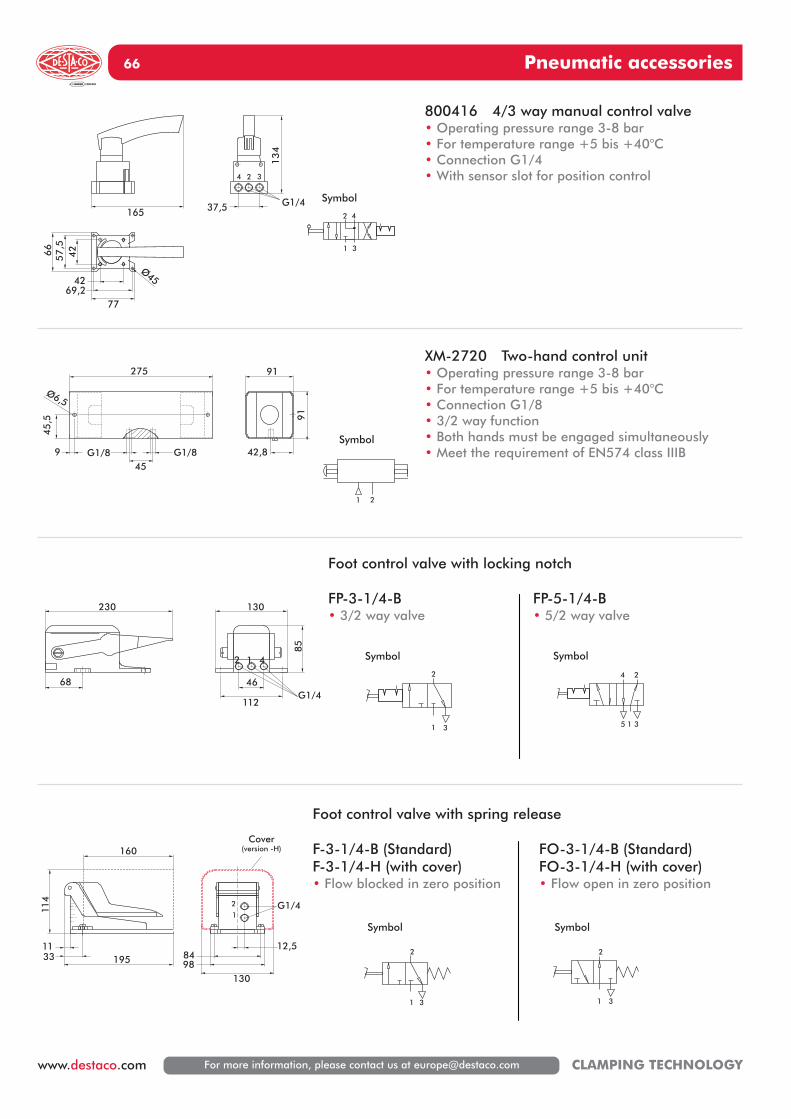
Pneumatic accessories66
For more information, please contact us at [email protected] CLAMPING TECHNOLOGY
165
134
37,5 G1/4
42Ø45
69,277
66
57,5
42
4 32
1 3
42
275
45G1/8G1/89
45
,5
Ø6,5
91
42,8
91
1 2
230
68
85
130
112
46G1/4
2 1 4
1 3
2
1 3
24
5
114
1953311
160
1309884
12,5
G1/42
1
Cover(version -H)
1 3
2
1 3
2
800416 4/3 way manual control valve• Operating pressure range 3-8 bar• For temperature range +5 bis +40°C• Connection G1/4• With sensor slot for position control
Foot control valve with locking notch
FP-3-1/4-B FP-5-1/4-B• 3/2 way valve • 5/2 way valve
Foot control valve with spring release
F-3-1/4-B (Standard) FO-3-1/4-B (Standard)F-3-1/4-H (with cover) FO-3-1/4-H (with cover)• Flow blocked in zero position • Flow open in zero position
XM-2720 Two-hand control unit• Operating pressure range 3-8 bar• For temperature range +5 bis +40°C• Connection G1/8• 3/2 way function• Both hands must be engaged simultaneously• Meet the requirement of EN574 class IIIB
Symbol
Symbol
Symbol Symbol
Symbol Symbol
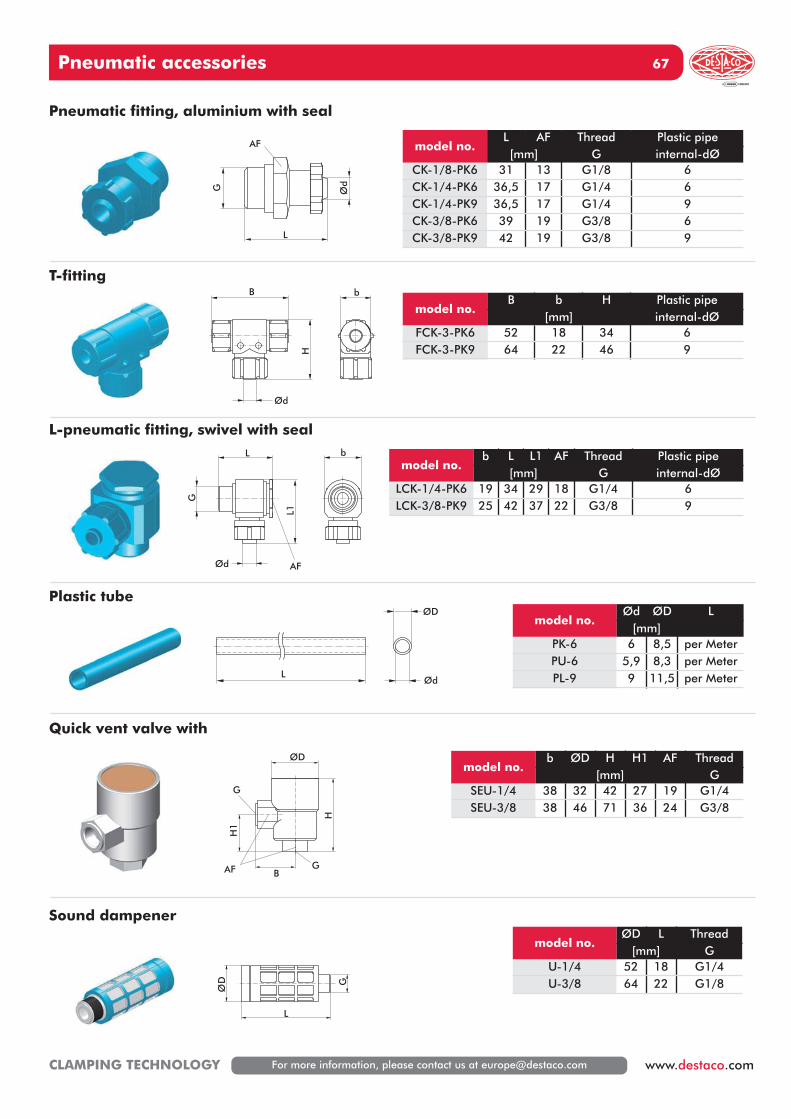
Pneumatic accessories 67
For more information, please contact us at [email protected] www.destaco.comCLAMPING TECHNOLOGY
model no.L AF Thread Plastic pipe[mm] G internal-dØ
CK-1/8-PK6 31 13 G1/8 6CK-1/4-PK6 36,5 17 G1/4 6CK-1/4-PK9 36,5 17 G1/4 9CK-3/8-PK6 39 19 G3/8 6CK-3/8-PK9 42 19 G3/8 9
model no.b L L1 AF Thread Plastic pipe
[mm] G internal-dØLCK-1/4-PK6 19 34 29 18 G1/4 6LCK-3/8-PK9 25 42 37 22 G3/8 9
model no.b ØD H H1 AF Thread
[mm] GSEU-1/4 38 32 42 27 19 G1/4SEU-3/8 38 46 71 36 24 G3/8
model no.Ød ØD L
[mm]PK-6 6 8,5 per MeterPU-6 5,9 8,3 per MeterPL-9 9 11,5 per Meter
model no.ØD L Thread
[mm] GU-1/4 52 18 G1/4U-3/8 64 22 G1/8
model no.B b H Plastic pipe
[mm] internal-dØFCK-3-PK6 52 18 34 6FCK-3-PK9 64 22 46 9
Pneumatic fitting, aluminium with seal
T-fitting
L-pneumatic fitting, swivel with seal
Plastic tube
Quick vent valve with
Sound dampener
ØdG
L
AF
Ød
HB b
L
L1
G
Ød AF
b
Ød
ØD
L
ØD
B
H
H1
G
GAF
L
DØ
G
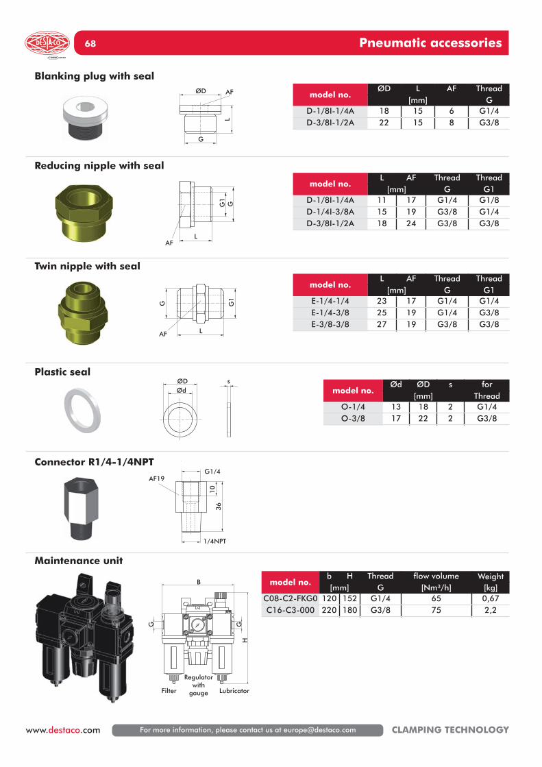
Pneumatic accessories68
For more information, please contact us at [email protected] CLAMPING TECHNOLOGY
Blanking plug with seal
L
ØD
G
AF
Reducing nipple with seal
G1
GL
AF
model no.L AF Thread Thread
[mm] G G1E-1/4-1/4 23 17 G1/4 G1/4E-1/4-3/8 25 19 G1/4 G3/8E-3/8-3/8 27 19 G3/8 G3/8
Twin nipple with seal
L
G G1
AF
model no.Ød ØD s for
[mm] ThreadO-1/4 13 18 2 G1/4O-3/8 17 22 2 G3/8
Plastic sealØDØd
s
36
1/4NPT
G1/4
10
AF19
Maintenance unit
GG
H
B
Filter
Regulatorwith
gauge Lubricator
model no.b H Thread flow volume Weight[mm] G [Nm³/h] [kg]
C08-C2-FKG0 120 152 G1/4 65 0,67C16-C3-000 220 180 G3/8 75 2,2
model no.L AF Thread Thread
[mm] G G1D-1/8I-1/4A 11 17 G1/4 G1/8D-1/4I-3/8A 15 19 G3/8 G1/4D-3/8I-1/2A 18 24 G3/8 G3/8
model no.ØD L AF Thread
[mm] GD-1/8I-1/4A 18 15 6 G1/4D-3/8I-1/2A 22 15 8 G3/8
Connector R1/4-1/4NPT

Notes 69
Notes
For more information, please contact us at [email protected] www.destaco.comCLAMPING TECHNOLOGY

Notes 71
Notes
For more information, please contact us at [email protected] www.destaco.comCLAMPING TECHNOLOGY
PRECISELY POSITIONING OUR CUSTOMERS FOR PRODUCTIVITY.
Workholding• Widest variety of workholding products• High durability and reliability• Flexible solutions for all applications• Custom products for unique requirements
Automation• Broad range of engineered automation products • Complementary products for modular integration • Unmatched accuracy, reliability and performance • Unparalleled global sales, service and engineering support
EUROPEGermanyTel: +49-6171-705-0Customer Service: [email protected]
FranceTel: +33-1-3996-5000Customer Service: [email protected]
UKTel: +44-1902-797980Customer Service: [email protected]
SpainTel: +34-936361680Customer Service: [email protected]
NetherlandsTel: +31-297285332Customer Service: [email protected]
ASIAThailandTel: +66-2-326-0812Customer Service: [email protected]
ChinaTel: +86-21-60812888Customer Service: [email protected]
IndiaTel: +91-80-41123421-426Customer Service: [email protected]
NORTH AMERICADE-STA-CO HeadquartersAuburn Hills, MichiganTel: 1.248.836.6700Toll Free: 1.888.DESTACOMarketing: [email protected] Service: [email protected]
Charlevoix, MichiganTel: 1.888.DESTACOCustomer Service: [email protected]
Wheeling, IllinoisTel: 1.800.645.5207Customer Service: [email protected]
Red Wing, MN (Central Research Laboratories)Tel: 651.385.2142Customer Service: [email protected]
SOUTH AMERICABrazilTel: 0800-124070Customer Service: [email protected]
DE-STA-CO GLOBAL LOCATIONS
To find a representative in your area,Please visit our websitewww.destaco.com Prec i se l y pos i t ion ing our cus tomers fo r p roduc t i v i t y.
DSC_CT_HY_C_0311_GB_3K