Embed Size (px)
Citation preview
ENGINEERING CONSULTANTS TSCHERNUTTER
UNIV.-PROF. DIPL.-ING. DR. TECHN. PETER TSCHERNUTTER, CIVIL ENGINEER SWORN AND COURT CERTIFIED EXPERT
FABRIKSTEIG 10/11, A-9500 VILLACH, AUSTRIA
TEL: +43 (4242) 23113-0, FAX: ext 3 E-Mail: [email protected]
Government reg.: 10885 VAT ID: ATU 266 55 009
Hydropower Cascade Project
Decan River, Kosovo
REVISER REPORT 3L2 AS-BUILT EVALUATION
Special excerpt:
Design Amendments of HPP Lumbardhi II
15th June 2018
ENGINEERING CONSULTANTS TSCHERNUTTER 2
D E C A N R I V E R H Y D R O P O W E R C A S C A D E P R O J E C T R E V I S E R R E P O R T 3 L 2 - A S - B U I L T E V A L U A T I O N D E S I G N A M E N D M E N T S O F H P P L U M B A R D H I I I
CONTENTSPART 1 – DOCUMENTATION OF THE REVISER COMPANY ................................................................................ 3
1.1 CIVIL ENGINEERING CERTIFICATE ..................................................................................................................................................... 3 1.2 QUALIFICATION PROFILE OF UNIV. PROF. DR. TECHN. TSCHERNUTTER ........................................................................................... 5 1.3 QUALIFICATION PROFILE OF EXPERT TEAM ..................................................................................................................................... 8
1.3.1 MILAN MULLEY ................................................................................................................................... 8 1.3.2 MICHAEL ADUNKA ............................................................................................................................. 11
1.4 LIST OF HYDROPOWER REFERENCE PROJECTS ............................................................................................................................... 14 1.5 DECISION ........................................................................................................................................................................................ 15 1.6 DECLARATION ................................................................................................................................................................................ 16
PART 2 – REVISER REPORT ........................................................................................................................... 17
2.1 GENERAL REMARKS ........................................................................................................................................................................ 17 2.2 TECHNICAL OVERVIEW ................................................................................................................................................................... 18
2.2.1 ORIGINAL DESIGN ACCORDING TO THE CONSTRUCTION PERMIT ................................................................... 18 2.2.2 OVERVIEW OF THE AS‐BUILT DESIGN ...................................................................................................... 18 2.2.3 INDIVIDUAL AS‐BUILT DESIGN OF EACH STAGE .......................................................................................... 20
2.2.3.1 EGU BELAJE ............................................................................................................................................ 20 2.2.3.2 EGU DECAN ............................................................................................................................................ 21 2.2.3.3 HPP LUMBARDHI II ................................................................................................................................... 21
2.2.4 DEVIATIONS FROM THE PRE‐FEASIBILITY DESIGN ...................................................................................... 22 2.2.4.1 EGU BELAJE ............................................................................................................................................ 22 2.2.4.2 EGU DECAN ............................................................................................................................................ 23
2.3 DESIGN AMENDMENTS OF HPP LUMBARDHI II .............................................................................................................................. 24 2.3.1 ORIGINAL DESIGN LAYOUT ................................................................................................................... 24 2.3.2 INVESTIGATION OF THE PROJECTED DAM LOCATION .................................................................................. 25
2.3.2.1 CORE DRILLINGS AND TRENCH ANALYSES .................................................................................................................. 25 2.3.2.2 HYDROGEOLOGICAL ANALYSES ..................................................................................................................... 27
2.3.3 CONSEQUENCES FROM INVESTIGATION RESULTS FOR THE STAGE DESIGN ...................................................... 28 2.3.3.1 DAM FEASIBILITY AND LOCATION ............................................................................................................................ 28 2.3.3.2 ALTERNATIVE DAM ALLOCATION ................................................................................................................... 29 2.3.3.3 ALTERNATIVE INTAKE ALLOCATION ................................................................................................................ 30
2.3.4 REVISED TWO‐STAGE INTAKE/DAM DESIGN ............................................................................................ 30 2.3.4.1 IMPLEMENTATION OF STAGE 1 – INTAKE .................................................................................................................. 30 2.3.4.2 INVESTIGATION REQUIREMENTS DURING STAGE 2 ....................................................................................................... 31
2.3.5 AS‐BUILT DESIGN OF HPP LUMBARDHI II ............................................................................................... 31 2.4 REVISER CHECK NR. 1 – PLAUSIBILITY OF THE DESIGN AMENDMENTS OF THE STAGE HPP LUMBARDHI II .................................... 35
2.4.1 ORIGINAL DAM/RESERVOIR DESIGN ...................................................................................................... 35 2.4.2 GEOTECHNICAL AND HYDROGEOLOGICAL IMPLICATIONS ........................................................................... 35 2.4.3 AMENDED INTAKE DESIGN .................................................................................................................. 36 2.4.4 CHANGE OF INSTALLED CAPACITY .......................................................................................................... 37 2.4.5 CHANGE IN ANNUAL PRODUCTION ........................................................................................................ 37 2.4.6 CONSEQUENCES FOR THE DECAN RIVER HPP CASCADE OPERATION ............................................................. 37 2.4.7 CONCLUSION OF THE REVISER ............................................................................................................... 38
2.5 REVISER CHECK NR. 2 – IMPACT ASSESSMENT OF THE AMENDED DESIGN FOR THE ENVIRONMENTAL CONDITIONS OF THE DECAN HPP STAGE ..................................................................................................................................................................................... 39
2.5.1 BASELINE ENVIRONMENTAL IMPACT CONDITIONS (EXTRACTED FROM EIA‐REPORT, MARCH 2011) ................. 39 2.5.1.1 EFFECTS UPON FLORA AND FAUNA, NATURAL HERITAGE AND GEOLOGY .................................................................. 39 2.5.1.2 CHANGES OF WATER QUALITY AND QUANTITY .......................................................................................................... 39
2.5.2 CONSTRUCTIVE EFFECTS OF THE AMENDED DESIGN ................................................................................... 40 2.5.2.1 PENSTOCK AND POWERHOUSE ..................................................................................................................... 40 2.5.2.2 INTAKE VERSUS DAM/RESERVOIR .................................................................................................................. 40
2.5.3 EFFECTS OF THE AMENDED DESIGN ON THE FLORA AND FAUNA, NATURAL HERITAGE AND GEOLOGY .................. 40 2.5.4 EFFECTS OF THE AMENDED DESIGN ON THE RESIDUAL FLOW OF THE HPP STAGE ............................................ 41 2.5.5 EFFECTS OF THE AMENDED DESIGN ON THE RECULTIVATION ....................................................................... 41 2.5.6 OTHER POTENTIAL EFFECTS OF THE AMENDED DESIGN IN RELATION TO THE EIA‐REPORT ................................. 43 2.5.7 CONCLUSION OF THE REVISER ............................................................................................................... 43
2.6 CONCLUDING VERDICT OF THE REVISER ........................................................................................................................................ 44
ENGINEERING CONSULTANTS TSCHERNUTTER 3
D E C A N R I V E R H Y D R O P O W E R C A S C A D E P R O J E C T R E V I S E R R E P O R T 3 L 2 - A S - B U I L T E V A L U A T I O N D E S I G N A M E N D M E N T S O F H P P L U M B A R D H I I I
PART 1 – DOCUMENTATION OF THE REVISER COMPANY
1.1 CIVIL ENGINEERING CERTIFICATE
ENGINEERING CONSULTANTS TSCHERNUTTER 4
D E C A N R I V E R H Y D R O P O W E R C A S C A D E P R O J E C T R E V I S E R R E P O R T 3 L 2 - A S - B U I L T E V A L U A T I O N D E S I G N A M E N D M E N T S O F H P P L U M B A R D H I I I
Translation
ENGINEERING CONSULTANTS TSCHERNUTTER 5
D E C A N R I V E R H Y D R O P O W E R C A S C A D E P R O J E C T R E V I S E R R E P O R T 3 L 2 - A S - B U I L T E V A L U A T I O N D E S I G N A M E N D M E N T S O F H P P L U M B A R D H I I I
1.2 QUALIFICATION PROFILE OF UNIV. PROF. DR. TECHN. TSCHERNUTTER University Professor Confirmation
ENGINEERING CONSULTANTS TSCHERNUTTER 6
D E C A N R I V E R H Y D R O P O W E R C A S C A D E P R O J E C T R E V I S E R R E P O R T 3 L 2 - A S - B U I L T E V A L U A T I O N D E S I G N A M E N D M E N T S O F H P P L U M B A R D H I I I
Translation

ENGINEERING CONSULTANTS TSCHERNUTTER 7
D E C A N R I V E R H Y D R O P O W E R C A S C A D E P R O J E C T R E V I S E R R E P O R T 3 L 2 - A S - B U I L T E V A L U A T I O N D E S I G N A M E N D M E N T S O F H P P L U M B A R D H I I I
Membership in professional Societies of Univ.-Prof. Tschernutter Austrian Chamber of Consulting and Civil Engineers ICOLD Committee "Materials for Fill Dams", Austrians representative (since 1985) Federal Ministry of Agriculture, Forestry, Environment and Water Management, Vienna,
Member of the Austrian Federal Commission on Dams (since 1987) Federal Ministry of Agriculture, Forestry, Environment and Water Management, Vienna,
Member of the Austrian Dam Safety Review Panel (since 1998) Vienna University of Technology, Professor for Hydraulic Engineering
Main fields of qualification
Senior Hydraulic Engineer Senior Dam Engineer Design and construction of hydropower plants and dams Hydropower and dam safety assessment and rehabilitation, monitoring and
maintenance Hydropower project feasibility studies and project management Risk and disaster management Hydropower, dam and reservoir operation Flood control Earthquake analysis Emergency plan design and implementation
Countries of work experience
Austria Albania Bulgaria Canada China Cyprus Germany Greece Indonesia Iran Israel Italy Kazakhstan Kosovo Poland Romania Sierra Leone Slovenia Spain Switzerland Turkey USA.
ENGINEERING CONSULTANTS TSCHERNUTTER 8
D E C A N R I V E R H Y D R O P O W E R C A S C A D E P R O J E C T R E V I S E R R E P O R T 3 L 2 - A S - B U I L T E V A L U A T I O N D E S I G N A M E N D M E N T S O F H P P L U M B A R D H I I I
1.3 QUALIFICATION PROFILE OF EXPERT TEAM
1.3.1 MILAN MULLEY
Main fields of qualification
Civil structural engineering Hydraulic structures Statics and stability analysis Soil mechanical engineering Hydraulic calculations
Reference projects
Salzburg AG, Austria, HPP Diessbach - Spillway and Dam Rehabilitation
HPP Hochsteiner, Austria – Rehabilitation and new weir, Flip gate, Fish bypass
HPP Steinwender, Austria – Basic and detail design, static calculations
HPP Wetzmann, Austria – Rehabilitation and detail design, static calculations
Vorarlberger Illwerke AG, Austria, HPP Rodund, Reservoirs Latschau and Rifa, Silvretta Dam – Approval of static calculations for intake, outlet structures, gates, etc. for the Austrian Ministry and Authorities
Austrian Hydropower, Verbund, HPP Hieflau, Reservoir Wag – Approval of static calculations for various hydraulic structures for the Austrian Ministry and Authorities
Embankment dam engineering, soil mechanic investigations, basic design and stability analyses (4 projects in Austria and 1 abroad)
Austrian Service for Torrent and Avalanche Control – Concrete Dams static calculation (Trübenbach, Vorderbergerbach, Wartschenbach, Klebensteiner Bach etc.)
Design and calculation of bottom outlets for hydraulic weirs, flood retention reservoirs and reservoirs for artificial snow (about 8 projects in Austria and abroad)
Static calculations and detail design for numerous pumping stations and hydropower plants (about 10 projects in Austria and abroad)
Hydraulic calculations and risk assessment, flood control (4 projects in Austria)
Other civil engineering projects, detail design and static calculations
ENGINEERING CONSULTANTS TSCHERNUTTER 9
D E C A N R I V E R H Y D R O P O W E R C A S C A D E P R O J E C T R E V I S E R R E P O R T 3 L 2 - A S - B U I L T E V A L U A T I O N D E S I G N A M E N D M E N T S O F H P P L U M B A R D H I I I
Diploma certificate
ENGINEERING CONSULTANTS TSCHERNUTTER 10
D E C A N R I V E R H Y D R O P O W E R C A S C A D E P R O J E C T R E V I S E R R E P O R T 3 L 2 - A S - B U I L T E V A L U A T I O N D E S I G N A M E N D M E N T S O F H P P L U M B A R D H I I I
Translation

ENGINEERING CONSULTANTS TSCHERNUTTER 11
D E C A N R I V E R H Y D R O P O W E R C A S C A D E P R O J E C T R E V I S E R R E P O R T 3 L 2 - A S - B U I L T E V A L U A T I O N D E S I G N A M E N D M E N T S O F H P P L U M B A R D H I I I
1.3.2 MICHAEL ADUNKA
Main fields of qualification
Civil structural engineering Hydraulic structures Soil mechanical engineering Hydraulic calculations
Reference projects
Public Authorities and Local Communities – Design, reconstruction, safety assessment of public bridges and bridges for hydraulic structures (about 30 bridges and tunnels)
Salzburg AG, Austria, HPP Diessbach - Spillway and Dam Rehabilitation, Project Salzburg AG, Austria, HPP Nassfeld – Cavern, Reservoir tunnels, intake and outlet
structure, basic and detail design, tendering, etc. Salzburg AG, Austria, HPP Zederhaus – Dam structure, safety assessment and
rehabilitation design KELAG, HPP Tröpolach, Austria – Detail design HPP Feistritz/Gail, Austria – Study and detail design
HPP Hochsteiner, Austria – Rehabilitation and new weir
HPP Wetzmann, Austria – Rehabilitation and detail design, tendering, site management
Hydraulic structures for flood protection and regulation, Government of Carinthia, Austria – Design, tendering
Austrian Service for Torrent and Avalanche Control – Concrete dams detail design (Feistritzbach, Kirchbach, Schmidbach, etc.)
HHP Rosenburg, Austria – Design and rehabilitation of dam, weir and adjacent structures, tendering, site management
River Management Plans, Government of Carinthia, Austria – Sediment transport, flood protection, hydrology etc.
Design of hydraulic weirs, flood retention reservoirs and reservoirs for artificial snow (about 12 projects in Austria and abroad)
HPP Forstnig, Austria – Basic and detail design
ENGINEERING CONSULTANTS TSCHERNUTTER 12
D E C A N R I V E R H Y D R O P O W E R C A S C A D E P R O J E C T R E V I S E R R E P O R T 3 L 2 - A S - B U I L T E V A L U A T I O N D E S I G N A M E N D M E N T S O F H P P L U M B A R D H I I I
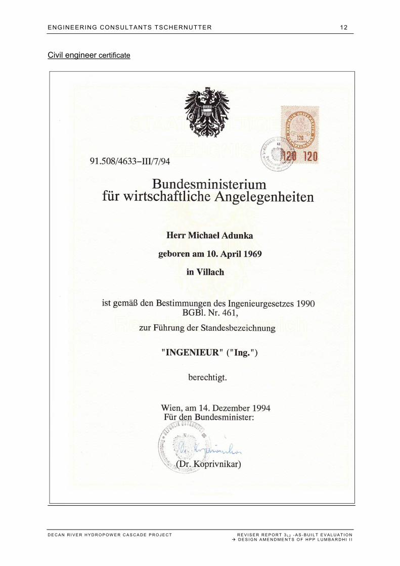
Civil engineer certificate
ENGINEERING CONSULTANTS TSCHERNUTTER 13
D E C A N R I V E R H Y D R O P O W E R C A S C A D E P R O J E C T R E V I S E R R E P O R T 3 L 2 - A S - B U I L T E V A L U A T I O N D E S I G N A M E N D M E N T S O F H P P L U M B A R D H I I I
Translation

ENGINEERING CONSULTANTS TSCHERNUTTER 14
D E C A N R I V E R H Y D R O P O W E R C A S C A D E P R O J E C T R E V I S E R R E P O R T 3 L 2 - A S - B U I L T E V A L U A T I O N D E S I G N A M E N D M E N T S O F H P P L U M B A R D H I I I
1.4 LIST OF HYDROPOWER REFERENCE PROJECTS Cooperation with Vienna Technical University
River run-off hydropower plant Ashta, Albania River run-off hydropower plant Gössendorf & Kalsdorf, Austria Embankment dams, overtopping and internal erosion laboratory tests River run-off hydropower plant Lehen, Austria Pump storage feasibility projects for four locations, Austria
Engineering Consultants Tschernutter (extract)
HPP Shala River (feasibility study), Albania HPP Bernegger (pump storage design), Austria HPP Atdorf (pump storage, reservoir design), Germany HPP Ebensee (pump storage design), Austria HPP La Romaine (dam engineering), Canada HPP Diessbach (high head plant, hydraulic structures and dam, spillway, redesign),
Austria HPP Hochsteiner (river run-off project), Austria HPP Kops II and Rodund II (pump storage scheme), Austria HPP Kühtai (high head pump storage plant, design with reservoirs and underground
powerhouse), Austria HPP Steinwender (river run-off project), Austria HPP Oflek (high head plant), Austria Drin river cascade, HPP Banja (refurbishment and basic design), Albania Devol river cascade and HPPs (safety assessment), Albania Antiesen, Flood retention dam and hydraulic structures (flood retention basin), Austria Homestake Dam (reservoir and distribution tunnels, intakes etc.), USA Dam safety assessment post-earthquake, Java, Indonesia 16 dams and reservoirs (dame safety expertise), Austria Bumbuna hydropower plant and dam (rockfill dam, concrete facing, project review
and assessment, design, monitoring), Sierra Leone Multipurpose reservoirs and 12 dams (review and assessment, dam safety, risk
management), Romania Wiori dam (flood protection reservoir, 35 m dam, design review), Poland Yntymak dam (project review, safety assessment, design optimization), Kazakhstan Kannaviou dam (feasibility study and design), Cyprus Kroussovitis dam (feasibility study, 70 m rockfill dam), Greece De Algar dam (rockfill dam, flood protection, design review), Spain Seneca pump storage scheme (safety assessment, site supervision), USA HPP Birecik (design and foundation, risk analysis, monitoring), Turkey Ahar dam (85 m rockfill dam, spillway and bottom outlet), Iran Tianhuangping HPP (pump storage scheme, upper reservoir, dams), China
ENGINEERING CONSULTANTS TSCHERNUTTER 15
D E C A N R I V E R H Y D R O P O W E R C A S C A D E P R O J E C T R E V I S E R R E P O R T 3 L 2 - A S - B U I L T E V A L U A T I O N D E S I G N A M E N D M E N T S O F H P P L U M B A R D H I I I
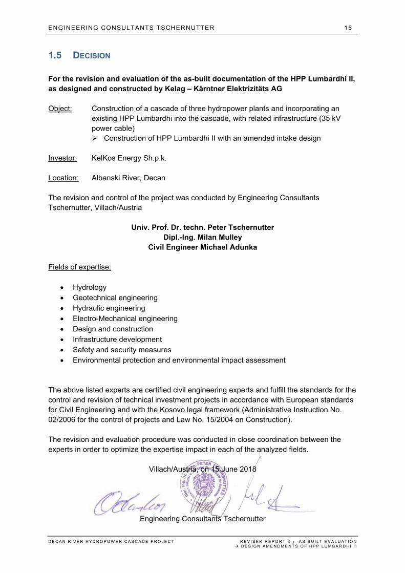
1.5 DECISION For the revision and evaluation of the as-built documentation of the HPP Lumbardhi II, as designed and constructed by Kelag – Kärntner Elektrizitäts AG Object: Construction of a cascade of three hydropower plants and incorporating an
existing HPP Lumbardhi into the cascade, with related infrastructure (35 kV power cable) Construction of HPP Lumbardhi II with an amended intake design
Investor: KelKos Energy Sh.p.k. Location: Albanski River, Decan The revision and control of the project was conducted by Engineering Consultants Tschernutter, Villach/Austria
Univ. Prof. Dr. techn. Peter Tschernutter Dipl.-Ing. Milan Mulley
Civil Engineer Michael Adunka Fields of expertise:
Hydrology Geotechnical engineering Hydraulic engineering Electro-Mechanical engineering Design and construction Infrastructure development Safety and security measures Environmental protection and environmental impact assessment
The above listed experts are certified civil engineering experts and fulfill the standards for the control and revision of technical investment projects in accordance with European standards for Civil Engineering and with the Kosovo legal framework (Administrative Instruction No. 02/2006 for the control of projects and Law No. 15/2004 on Construction). The revision and evaluation procedure was conducted in close coordination between the experts in order to optimize the expertise impact in each of the analyzed fields.
Villach/Austria, on 15 June 2018
Engineering Consultants Tschernutter
ENGINEERING CONSULTANTS TSCHERNUTTER 16
D E C A N R I V E R H Y D R O P O W E R C A S C A D E P R O J E C T R E V I S E R R E P O R T 3 L 2 - A S - B U I L T E V A L U A T I O N D E S I G N A M E N D M E N T S O F H P P L U M B A R D H I I I
1.6 DECLARATION After an in-deep revision and evaluation of the presented as-built documentation of the HPP Lumbardhi II and based on related field visits, it is herewith confirmed that the amended design is founded, and the construction implementation fulfils all criteria as set out by the Law on Construction and all other legal standards in force. Object: Construction of a cascade of three hydropower plants and incorporating an
existing HPP Lumbardhi into the cascade, with related infrastructure (35 kV power cable) Construction of HPP Lumbardhi II with an amended intake design
Investor: KelKos Energy Sh.p.k. Location: Albanski River, Decan
Univ. Prof. Dr. techn. Peter Tschernutter Dipl.-Ing. Milan Mulley
Civil Engineer Michael Adunka Herewith we declare that the professional revision and evaluation of the as-built documentation, designed and constructed by Kelag – Kärntner Elektrizitäts AG, has been conducted in accordance with the legal standards and valid administrative directions of MESP.
Villach/Austria, on 15 June 2018
Engineering Consultants Tschernutter
ENGINEERING CONSULTANTS TSCHERNUTTER 17
D E C A N R I V E R H Y D R O P O W E R C A S C A D E P R O J E C T R E V I S E R R E P O R T 3 L 2 - A S - B U I L T E V A L U A T I O N D E S I G N A M E N D M E N T S O F H P P L U M B A R D H I I I
PART 2 – REVISER REPORT
2.1 GENERAL REMARKS The investor KelKos Energy Sh.p.k. has requested the consulting and expert team Engineering Consultants Tschernutter, Villach/Austria, to undertake a special revision of the as-built documentation of the HPP Lumbardhi II, which is part of a series of three new-built hydropower plants along Decan River, which shall operate together with the existing hydropower plant Lumbardhi of KelKos Energy as four-stage hydropower cascade. The special revision shall focus on the plausibility and founding of the amended construction design and its constructive implementation of HPP Lumbardhi II. This Special Excerpt of the as-built Reviser Report of the Decan River hydropower plant cascade refers to the as-built documentation compendium of the HPP Lumbardhi II, comprising 3 files with more than 200 pages and more than 50 design plans of as-built documentation, which was submitted by KelKos Energy to the Kosovo Ministry of Environment and Spatial Planning (MESP). The project was designed by the company Kelag – Kärntner Elektrizitäts AG, Klagenfurt/Austria. After reviewing and analyzing the available documentation, Engineering Consultants Tschernutter has agreed to conduct the revision of the as-built documentation of the project.
ENGINEERING CONSULTANTS TSCHERNUTTER 18
D E C A N R I V E R H Y D R O P O W E R C A S C A D E P R O J E C T R E V I S E R R E P O R T 3 L 2 - A S - B U I L T E V A L U A T I O N D E S I G N A M E N D M E N T S O F H P P L U M B A R D H I I I
2.2 TECHNICAL OVERVIEW
2.2.1 ORIGINAL DESIGN ACCORDING TO THE CONSTRUCTION PERMIT
The original design, which was assessed and approved through a Reviser Report of the undersigned experts in April 2012, had foreseen the following stage parameters: EGU (energy generation unit) “Decan”
PA = 8,4 MW GoE = 28 GWh
EGU “Belaje”
PA = 9,2 MW GoE = 29,7 GWh
HPP (hydropower plant) “Lumbardhi II”
PA = 5,5 MW GoE = 30 GWh (including reservoir related cascade potential)
Rockfill dam with a maximum height from foundation to crest of 40 m Max. storage volume of the reservoir of 3,9 Mio. m3
Existing HPP Lumbardhi (upgraded installations)
PA = 8,2 MW GoE = 21 GWh
2.2.2 OVERVIEW OF THE AS-BUILT DESIGN
In principle, the as-built design of the Decan River HPP cascade follows the overall layout of
the pre-feasibility study and the related Construction Permissions, issued by MESP.
However, two major design amendments had to be implemented, both caused by technical
reasons.
Amendment 1:
The individual length of the stages EGU Decan and EGU Belaje, with a planned total
installed capacity of 17,6 MW, had to be adjusted to meet the requirements for the optimal
location of the powerhouse of EGU Belaje.
ENGINEERING CONSULTANTS TSCHERNUTTER 19
D E C A N R I V E R H Y D R O P O W E R C A S C A D E P R O J E C T R E V I S E R R E P O R T 3 L 2 - A S - B U I L T E V A L U A T I O N D E S I G N A M E N D M E N T S O F H P P L U M B A R D H I I I
The originally planned location of the power house turned out to be
a. Situated just inside the Special Protective Zone of Decan Monastery,
b. Placed on a grassland parcel next to the river with unclear ownership status,
c. Facing difficult accessibility from the existing public road.
Consequently, the final location of the powerhouse Belaje had to be moved upstream to a
place, which is
a. Located just outside the Special Protective Zone of Decan Monastery,
b. Placed on a parcel, which is covered by the servitude contract with Decan
Municipality and
c. directly accessible from the public road.
The as-built installed capacity of EGU Belaje and EGU Decan totals with 17,9 MW.
Amendment 2:
According to the pre-feasibility study, the original design of the stage HPP Lumbardhi II
foresees an intake structure, consisting of a dam and related reservoir with estimated 3,5-4
Mio. m3 volume, situated at Zali Rupe.
However, as further detailed in this report, the geotechnical and hydrogeological
investigations into the projected basement of the dam location revealed a
a. lack of the required solid rock basement beyond a confirmed drilling depth of 85 m
b. substantial underground water transition through the projected basement of the dam,
with up to 50% of the hydrogeological water potential being lost across the entrance
swell of Zali Rupe.
To compensate the above described problems, the amended design foresees a classic
intake structure along with the example of EGU Decan and EGU Belaje.
The intake is located at a point downstream Albanski River, where a calculated more than
90% of the water, transiting underground, has surfaced again.
Based on the hydrogeological conditions of the new intake location, the installed capacity
increased from 5,5 MW to 6,2 MW. Upon request of the licensing authority, this Revisor
Report extract will assess in detail the plausibility of this design and capacity amendment.
Based on future continuous hydrogeological measurements of the operational intake
structure, the water transition from Zali Rupe shall be identified in more detail. Together with
additional test drillings at an alternative dam location inside Zali Rupe, the geotechnical and
ENGINEERING CONSULTANTS TSCHERNUTTER 20
D E C A N R I V E R H Y D R O P O W E R C A S C A D E P R O J E C T R E V I S E R R E P O R T 3 L 2 - A S - B U I L T E V A L U A T I O N D E S I G N A M E N D M E N T S O F H P P L U M B A R D H I I I
hydrogeological conditions shall be assessed for a redesigned and height-reduced dam,
which would be feasible for the overall stage operation.
In phase 2 this concept should be assessed from the economical and operational viewpoint and – in case of positive investigation results – an alternative dam/reservoir location be presented to the authorities. From the expert point of view, a minimum of 2 years shall be calculated for these investigations.
2.2.3 INDIVIDUAL AS-BUILT DESIGN OF EACH STAGE
2.2.3.1 EGU BELAJE
The as-built design of the stage EGU Belaje shows the following parameters:
Catchment area est. 91 km2
Q = 7 m3/s
H = 128 m
P = 8,1 MW
A = 24,9 GWh
Two intakes are constructed, one with a fix weir, one with a Tyrolean weir. Both intakes are
connected with flushing channel, flushing gate, sedimentation tank, coarse track and fish
ladder. They connect into the collecting basin EGU Belaje.
The penstock with a total length of 3.270 m is embedded into the existing road. The GRP
pipes have a diameter of 2.000-1.600 mm.
The powerhouse is free-standing with an indoor crane. Its tailrace channel is connected with
the collecting basin of the lower stage EGU Decan.
Two Francis turbines are installed with the following parameters:
P1 = 5.268 kW
n1 = 500 RPM
Q1 = 4,6 m3/s
P2 = 2.796 kW
N2 = 1.000 RPM
Q2 = 2,4 m3/s
Two generators (three-phase synchronous) are connected, with related switchgear, control
equipment and transformer.
ENGINEERING CONSULTANTS TSCHERNUTTER 21
D E C A N R I V E R H Y D R O P O W E R C A S C A D E P R O J E C T R E V I S E R R E P O R T 3 L 2 - A S - B U I L T E V A L U A T I O N D E S I G N A M E N D M E N T S O F H P P L U M B A R D H I I I
2.2.3.2 EGU DECAN
The as-built design of the stage EGU Decan shows the following parameters:
Catchment area est. 112 km2
Q = 7 m3/s
H = 178 m
P = 9,81 MW
A = 42,3 GWh
The intake is constructed with a fix weir and connected flushing channel, flushing gate,
sedimentation tank, coarse track and fish ladder. It connects with the collecting basin EGU
Decan.
The penstock with a total length of 5.600 m is embedded into the existing road. The GRP
pipes have a diameter of 2.200-1.800 mm.
The powerhouse is semi-submerged with an indoor crane. Its tailrace channel empties into
Decan River.
Two Francis turbines are installed with the following parameters:
P1 = 6.655 kW
n1 = 600 RPM
Q1 = 4,6 m3/s
P2 = 3.154 kW
N2 = 1.000 RPM
Q2 = 2,4 m3/s
Two generators (three-phase synchronous) are connected, with related switchgear, control
equipment and transformer.
2.2.3.3 HPP LUMBARDHI II
The as-built design of the stage HPP Lumbardhi II shows the following parameters:
Catchment area est. 18,3 km2
Q = 3 m3/s
H = 231,85 m
P = 6,2 MW
A = 19 GWh
ENGINEERING CONSULTANTS TSCHERNUTTER 22
D E C A N R I V E R H Y D R O P O W E R C A S C A D E P R O J E C T R E V I S E R R E P O R T 3 L 2 - A S - B U I L T E V A L U A T I O N D E S I G N A M E N D M E N T S O F H P P L U M B A R D H I I I
The intake is constructed with a fix weir with side intake, connected flushing channel, flushing
gate, sedimentation tank, coarse track and fish ladder.
The penstock with a total length of 2.350 m is embedded into the existing road. The GRP
pipes have a diameter of 1.400 and 1.200 mm.
The powerhouse is free-standing with an indoor crane. The tailrace channel is connected to
the Intake 1 of HPP Lumbardhi.
One Pelton turbine is installed with the following parameters:
P = 6.200 kW
n = 600 RPM
Q = 3 m3/s
One generator (three-phase synchronous) is connected, with related switchgear, control
equipment and transformer.
2.2.4 DEVIATIONS FROM THE PRE-FEASIBILITY DESIGN
2.2.4.1 EGU BELAJE
As described in point 2.2.2, the overall length of the stage EGU Belaje needed to be reduced
due to formal and legal reasons and reasons of logistics. Consequently, the gross head
(overall stage length) of EGU Belaje was amended from the pre-feasibility value of 173 m to
128 m.
Accordingly, the installed capacity was changed amended from the pre-feasibility value of 9,2
MW to 8,1 MW.
This effects an estimated annual production of 24,9 GWh instead of projected 29,7 GWh.
With the above change of parameters, the following infrastructural parameters changed:
Changed allocation of the powerhouse
Decreased length of the penstock
Changed technical parameters of the turbines
Regarding the operational conditions, listed in the Environmental Impact Assessment Report
(March 2011), no deviations to the positive or negative for the overall cascade segment
Belaje-Decan can be assessed from the expert point of view.
ENGINEERING CONSULTANTS TSCHERNUTTER 23
D E C A N R I V E R H Y D R O P O W E R C A S C A D E P R O J E C T R E V I S E R R E P O R T 3 L 2 - A S - B U I L T E V A L U A T I O N D E S I G N A M E N D M E N T S O F H P P L U M B A R D H I I I
The decrease in penstock length of the stage EGU Belaje compensates overall with the
increase in penstock length of EGU Decan. This does not affect the overall environmental
impacts during the construction phase of these two stages.
2.2.4.2 EGU DECAN
As described in point 2.2.2, the overall length of the stage EGU Belaje needed to be reduced
due to formal and legal reasons and reasons of logistics. Consequently, the overall length of
the stage EGU Decan needed to be adjusted/increased for the same amount.
The gross head (overall stage length) of EGU Decan was amended from the pre-feasibility
value of 127 m to 178 m.
Accordingly, the installed capacity was changed amended from the pre-feasibility value of 8,4
MW to 9,8 MW.
This effects an estimated annual production of 42 GWh instead of projected 28 GWh.
With the above change of parameters, the following infrastructural parameters changed:
Changed allocation of the Intake
Increased length of the penstock
Changed technical parameters and capacity of the turbines
With regard to the operational conditions, listed in the Environmental Impact Assessment
Report (March 2011), no deviations to the positive or negative for the overall cascade
segment Belaje-Decan can be assessed from the expert point of view.
The increase in penstock length of the stage EGU Decan compensates overall with the
decrease in penstock length of EGU Belaje. This does not affect environmental impacts
during the construction phase of these two stages.
ENGINEERING CONSULTANTS TSCHERNUTTER 24
D E C A N R I V E R H Y D R O P O W E R C A S C A D E P R O J E C T R E V I S E R R E P O R T 3 L 2 - A S - B U I L T E V A L U A T I O N D E S I G N A M E N D M E N T S O F H P P L U M B A R D H I I I
2.3 DESIGN AMENDMENTS OF HPP LUMBARDHI II
2.3.1 ORIGINAL DESIGN LAYOUT
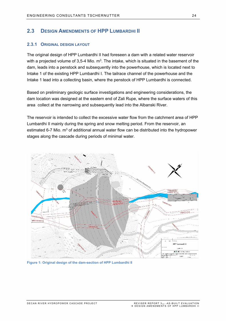
The original design of HPP Lumbardhi II had foreseen a dam with a related water reservoir
with a projected volume of 3,5-4 Mio. m3. The intake, which is situated in the basement of the
dam, leads into a penstock and subsequently into the powerhouse, which is located next to
Intake 1 of the existing HPP Lumbardhi I. The tailrace channel of the powerhouse and the
Intake 1 lead into a collecting basin, where the penstock of HPP Lumbardhi is connected.
Based on preliminary geologic surface investigations and engineering considerations, the
dam location was designed at the eastern end of Zali Rupe, where the surface waters of this
area collect at the narrowing and subsequently lead into the Albanski River.
The reservoir is intended to collect the excessive water flow from the catchment area of HPP
Lumbardhi II mainly during the spring and snow melting period. From the reservoir, an
estimated 6-7 Mio. m3 of additional annual water flow can be distributed into the hydropower
stages along the cascade during periods of minimal water.
Figure 1: Original design of the dam-section of HPP Lumbardhi II
ENGINEERING CONSULTANTS TSCHERNUTTER 25
D E C A N R I V E R H Y D R O P O W E R C A S C A D E P R O J E C T R E V I S E R R E P O R T 3 L 2 - A S - B U I L T E V A L U A T I O N D E S I G N A M E N D M E N T S O F H P P L U M B A R D H I I I
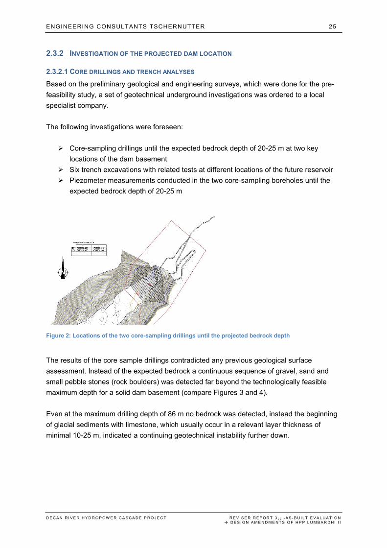
2.3.2 INVESTIGATION OF THE PROJECTED DAM LOCATION
2.3.2.1 CORE DRILLINGS AND TRENCH ANALYSES
Based on the preliminary geological and engineering surveys, which were done for the pre-
feasibility study, a set of geotechnical underground investigations was ordered to a local
specialist company.
The following investigations were foreseen:
Core-sampling drillings until the expected bedrock depth of 20-25 m at two key
locations of the dam basement
Six trench excavations with related tests at different locations of the future reservoir
Piezometer measurements conducted in the two core-sampling boreholes until the
expected bedrock depth of 20-25 m
Figure 2: Locations of the two core-sampling drillings until the projected bedrock depth
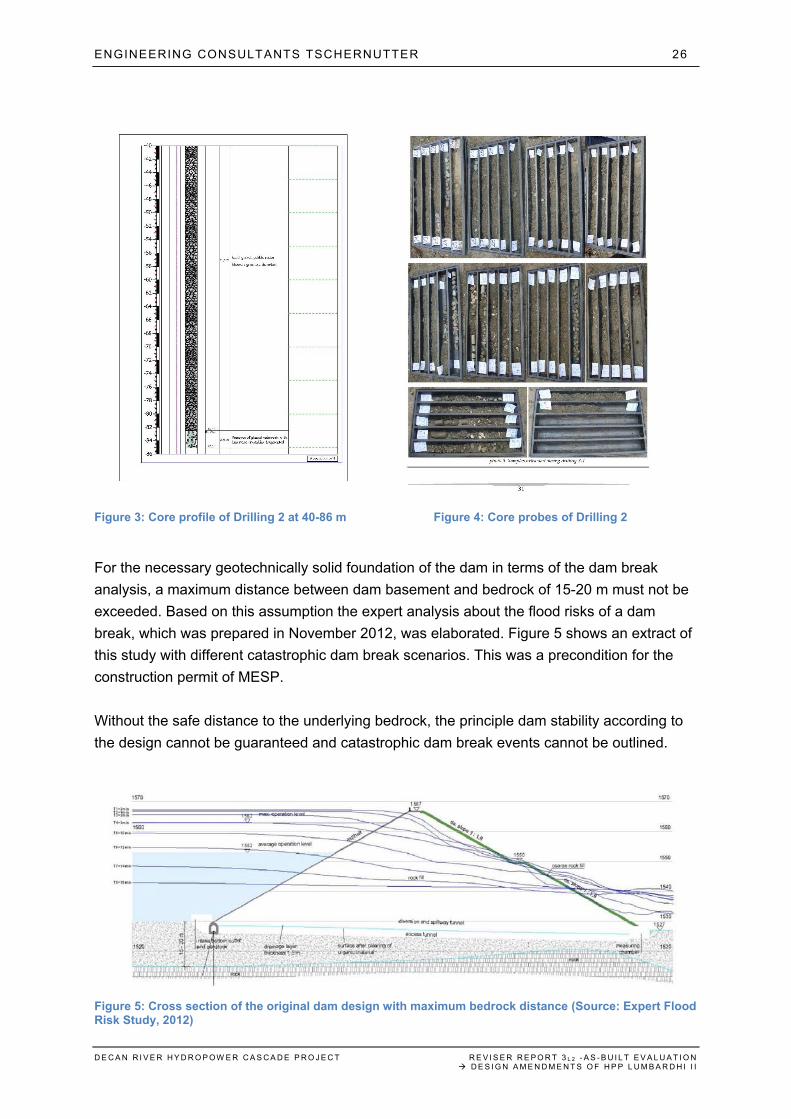
The results of the core sample drillings contradicted any previous geological surface
assessment. Instead of the expected bedrock a continuous sequence of gravel, sand and
small pebble stones (rock boulders) was detected far beyond the technologically feasible
maximum depth for a solid dam basement (compare Figures 3 and 4).
Even at the maximum drilling depth of 86 m no bedrock was detected, instead the beginning
of glacial sediments with limestone, which usually occur in a relevant layer thickness of
minimal 10-25 m, indicated a continuing geotechnical instability further down.
ENGINEERING CONSULTANTS TSCHERNUTTER 26
D E C A N R I V E R H Y D R O P O W E R C A S C A D E P R O J E C T R E V I S E R R E P O R T 3 L 2 - A S - B U I L T E V A L U A T I O N D E S I G N A M E N D M E N T S O F H P P L U M B A R D H I I I
Figure 3: Core profile of Drilling 2 at 40-86 m Figure 4: Core probes of Drilling 2
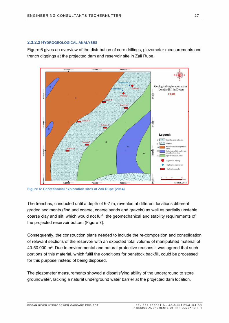
For the necessary geotechnically solid foundation of the dam in terms of the dam break
analysis, a maximum distance between dam basement and bedrock of 15-20 m must not be
exceeded. Based on this assumption the expert analysis about the flood risks of a dam
break, which was prepared in November 2012, was elaborated. Figure 5 shows an extract of
this study with different catastrophic dam break scenarios. This was a precondition for the
construction permit of MESP.
Without the safe distance to the underlying bedrock, the principle dam stability according to
the design cannot be guaranteed and catastrophic dam break events cannot be outlined.
Figure 5: Cross section of the original dam design with maximum bedrock distance (Source: Expert Flood Risk Study, 2012)
ENGINEERING CONSULTANTS TSCHERNUTTER 27
D E C A N R I V E R H Y D R O P O W E R C A S C A D E P R O J E C T R E V I S E R R E P O R T 3 L 2 - A S - B U I L T E V A L U A T I O N D E S I G N A M E N D M E N T S O F H P P L U M B A R D H I I I
2.3.2.2 HYDROGEOLOGICAL ANALYSES
Figure 6 gives an overview of the distribution of core drillings, piezometer measurements and
trench diggings at the projected dam and reservoir site in Zali Rupe.
Figure 6: Geotechnical exploration sites at Zali Rupe (2014)
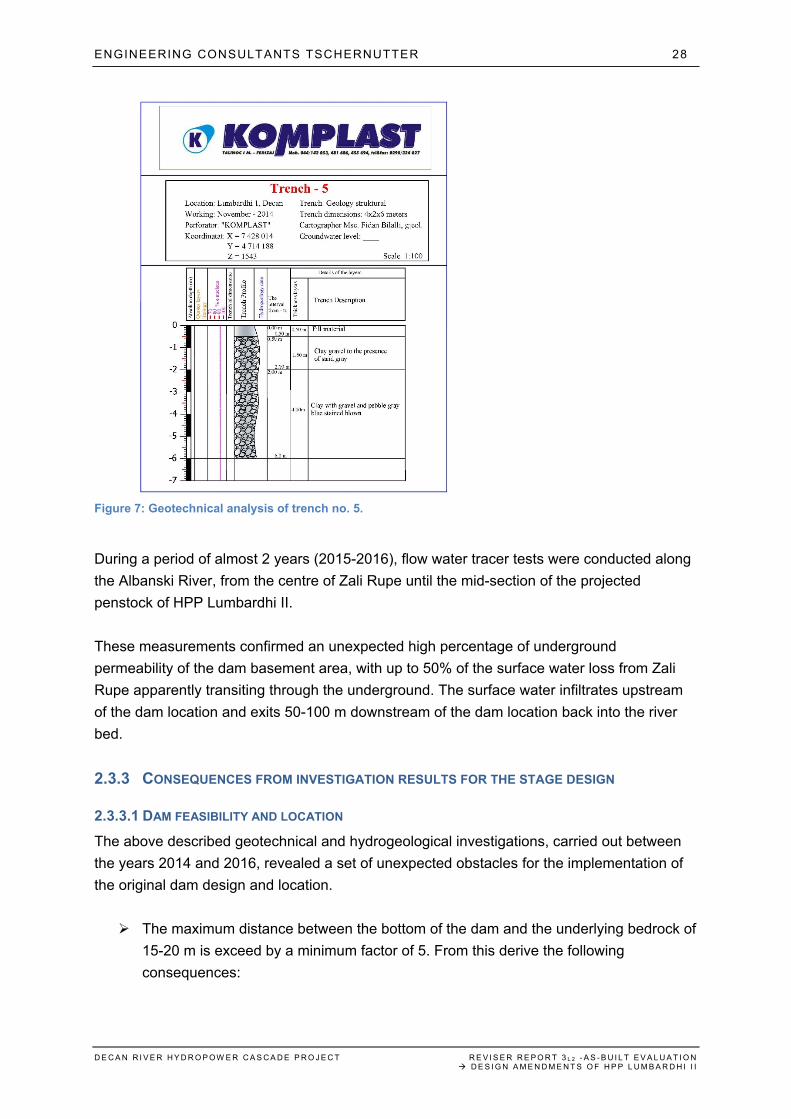
The trenches, conducted until a depth of 6-7 m, revealed at different locations different
graded sediments (find and coarse, coarse sands and gravels) as well as partially unstable
coarse clay and silt, which would not fulfil the geomechanical and stability requirements of
the projected reservoir bottom (Figure 7).
Consequently, the construction plans needed to include the re-composition and consolidation
of relevant sections of the reservoir with an expected total volume of manipulated material of
40-50.000 m3. Due to environmental and natural protective reasons it was agreed that such
portions of this material, which fulfil the conditions for penstock backfill, could be processed
for this purpose instead of being disposed.
The piezometer measurements showed a dissatisfying ability of the underground to store
groundwater, lacking a natural underground water barrier at the projected dam location.
ENGINEERING CONSULTANTS TSCHERNUTTER 28
D E C A N R I V E R H Y D R O P O W E R C A S C A D E P R O J E C T R E V I S E R R E P O R T 3 L 2 - A S - B U I L T E V A L U A T I O N D E S I G N A M E N D M E N T S O F H P P L U M B A R D H I I I
Figure 7: Geotechnical analysis of trench no. 5.
During a period of almost 2 years (2015-2016), flow water tracer tests were conducted along
the Albanski River, from the centre of Zali Rupe until the mid-section of the projected
penstock of HPP Lumbardhi II.
These measurements confirmed an unexpected high percentage of underground
permeability of the dam basement area, with up to 50% of the surface water loss from Zali
Rupe apparently transiting through the underground. The surface water infiltrates upstream
of the dam location and exits 50-100 m downstream of the dam location back into the river
bed.
2.3.3 CONSEQUENCES FROM INVESTIGATION RESULTS FOR THE STAGE DESIGN
2.3.3.1 DAM FEASIBILITY AND LOCATION
The above described geotechnical and hydrogeological investigations, carried out between
the years 2014 and 2016, revealed a set of unexpected obstacles for the implementation of
the original dam design and location.
The maximum distance between the bottom of the dam and the underlying bedrock of
15-20 m is exceed by a minimum factor of 5. From this derive the following
consequences:
ENGINEERING CONSULTANTS TSCHERNUTTER 29
D E C A N R I V E R H Y D R O P O W E R C A S C A D E P R O J E C T R E V I S E R R E P O R T 3 L 2 - A S - B U I L T E V A L U A T I O N D E S I G N A M E N D M E N T S O F H P P L U M B A R D H I I I
o The projected dam location, together with the projected dam design cannot
provide the necessary structural stability for a safe construction and operation
of the dam.
o The safety conditions for the prevention of a catastrophic dam break, as
defined in an expert flood study of 20123, cannot be fulfilled.
o Consequently, the Construction Permit of MESP for the dam, which relies on
the compliance with these flood risk calculations, cannot be upheld.
The composition of the reservoir basement reveals substantial geotechnical deficits in
relation to the minimal requirements. Consequently, relevant sections of the reservoir
basement would need geotechnical processing and preparation, with an expected
volume of manipulated material of 40-50.000 m3.
Apart from the dramatic deficits regarding the basement at the projected dam
location, the substantial underground water loss through the entrance swell of Zali
Rupe questions in principle the projected dam location. Without the required water
barrier in the foundation, the projected reservoir would leak permanently to such an
extent, that no coordinated reservoir operation can be guaranteed. In a worst case,
the reservoir would be dry during most of the calendar year.
2.3.3.2 ALTERNATIVE DAM ALLOCATION
Considering the existing geotechnical and hydrologeological obstacles at the projected dam
location, which are summarized in point 2.3.3.1, the implementation of the original
dam/reservoir design is impossible from an expert point of view.
At this point it seems useful to reflect basically on the principle advantages of the
dam/reservoir at all.
With a designed reservoir volume of 3,5-4 Mio. m3 of water, an estimated average total of
6,5-7 Mio. m3 of additional water volume can be utilized during the year and can be
distributed in a very efficient way over the HPP cascade of Decan. This would enable an
estimated additional production of 10-12 GWh per year. Furthermore, it would increase the
minimal natural water flow during summer and dry periods.
With the investigated geotechnical and hydrogeological situation, an alternative dam location
with solid dam foundation conditions and in a certain distance from the entrance swell of Zali
Rupe, would most likely be located upstream somewhere in the center part of Zali Rupe.
However, any alternative dam location would need to fulfill the principle geotechnical and
hydrogeological conditions as described above:
Maximum distance between dam basement and bedrock of 15-20 m
ENGINEERING CONSULTANTS TSCHERNUTTER 30
D E C A N R I V E R H Y D R O P O W E R C A S C A D E P R O J E C T R E V I S E R R E P O R T 3 L 2 - A S - B U I L T E V A L U A T I O N D E S I G N A M E N D M E N T S O F H P P L U M B A R D H I I I
Existence of water retaining layers in the underground of the dam, preventing a
natural leakage of the reservoir.
Under the assumption of a feasible alternative dam location in the middle of Zali Rupe, the
dam size (height) as well as the reservoir volume would decrease substantially. The
estimated maximum volume of an alternative reservoir would range between 1-1,5 Mio. m3 at
the best.
This aspect has to be considered in a cost-benefit analysis for the alternative location,
provided that the geotechnical and hydrogeological conditions are fulfilled at all.
2.3.3.3 ALTERNATIVE INTAKE ALLOCATION
With the above described geotechnical and hydrogeological obstacles for the projected
dam/reservoir location, the original cascade concept for the four hydropower plants along
Decan River cannot be implemented. Effectively the design of the HPP Lumbardhi II requires
an amendment of the intake area.
A first re-design option would be to maintain the intake at the original location, without
integrating it into the original dam concept. However, with the described substantial water
losses through the underground along the entrance swell of Zali Rupe, this design would be
both unlogic and highly ineffective.
The remaining second option is to relocate the original intake in the direction downstream so
that more than 90% percent of the underground water flow has re-surfaced at that relocated
new intake point.
2.3.4 REVISED TWO-STAGE INTAKE/DAM DESIGN
With the geotechnical and hydrogeological scenarios as described above, KelKos Energy
decided reasonably to transfer the original intake design of HPP into a two-stage concept.
2.3.4.1 IMPLEMENTATION OF STAGE 1 – INTAKE
To complete the stage design of HPP Lumbardhi II and meet the timewise limitations of the
construction permit of ERO, KelKos Energy made the right decision to:
Postpone the construction of the original dam/reservoir concept, until sufficient
further geotechnical and hydrogeological investigations can confirm a feasible
alternative location.
Re-locate the intake from Zali Rupe to that point downstream along Albanski
River, where – according to the earlier conducted water flow tracer tests – more
ENGINEERING CONSULTANTS TSCHERNUTTER 31
D E C A N R I V E R H Y D R O P O W E R C A S C A D E P R O J E C T R E V I S E R R E P O R T 3 L 2 - A S - B U I L T E V A L U A T I O N D E S I G N A M E N D M E N T S O F H P P L U M B A R D H I I I
than 90% of the water from the catchment area of HPP Lumbardhi II can be
utilized to produce energy.
The intake design would follow the example of the earlier constructed stages EGU Decan
and EGU Belaje, minimizing the environmental impact as prescribed in the EIA-Report.
2.3.4.2 INVESTIGATION REQUIREMENTS DURING STAGE 2
As described in point 2.3.2, geotechnical and hydrogeological investigations at the alternative
location of the dam need to focus on two critical parameters:
Exact profile of the underlying bedrock surface at the alternative dam location. A
maximum vertical distance of 15-20 m between the ground surface and the
bedrock surface should be confirmed. The applied tests must include core drilling
and piezometer tests.
High impermeability of the reservoir underground in general and the dam
basement in particular.
Hydrogeological measurements and analysis of the real-time water flow at the
new intake and comparison with earlier results from water tracer tests along the
entrance swell of Zali Rupe. In order to acquire authoritative timelines, these
analyses should cover a minimum of 24 months.
Considering this background, the expert recommends conceding from MESP to KelKos
Energy a test period until mid-2020.
At the end of this period, KelKos Energy should have a clearer picture of the geotechnical
and hydrogeological conditions along Zali Rupe, substantiating the chances for implementing
a relocated dam/reservoir design, considering also the existing intake.
The final decision about a potential extension of the stage HPP Lumbardhi II should be
agreed between the Investor and the Authority.
2.3.5 AS-BUILT DESIGN OF HPP LUMBARDHI II
The amended intake design for the first stage of HPP Lumbardhi II follows the example of the
other newly built HPP stages EGU Decan and EGU Belaje.
The intake structure consists of a fixed weir with side intake, flushing channel, flushing gate,
sedimentation tank, coarse rack and fish ladder. The intake is located downstream at an
estimated vertical distance of 60 m from the entrance swell of Zali Rupe.
The location of the intake was selected based on the following parameters:
ENGINEERING CONSULTANTS TSCHERNUTTER 32
D E C A N R I V E R H Y D R O P O W E R C A S C A D E P R O J E C T R E V I S E R R E P O R T 3 L 2 - A S - B U I L T E V A L U A T I O N D E S I G N A M E N D M E N T S O F H P P L U M B A R D H I I I
Hydrogeological situation (>90% of the tracible underground waterflow resurfaced
at that point of the river)
Topographically optimized position of the intake structures in terms of accessibility
and integration into the riverbed.
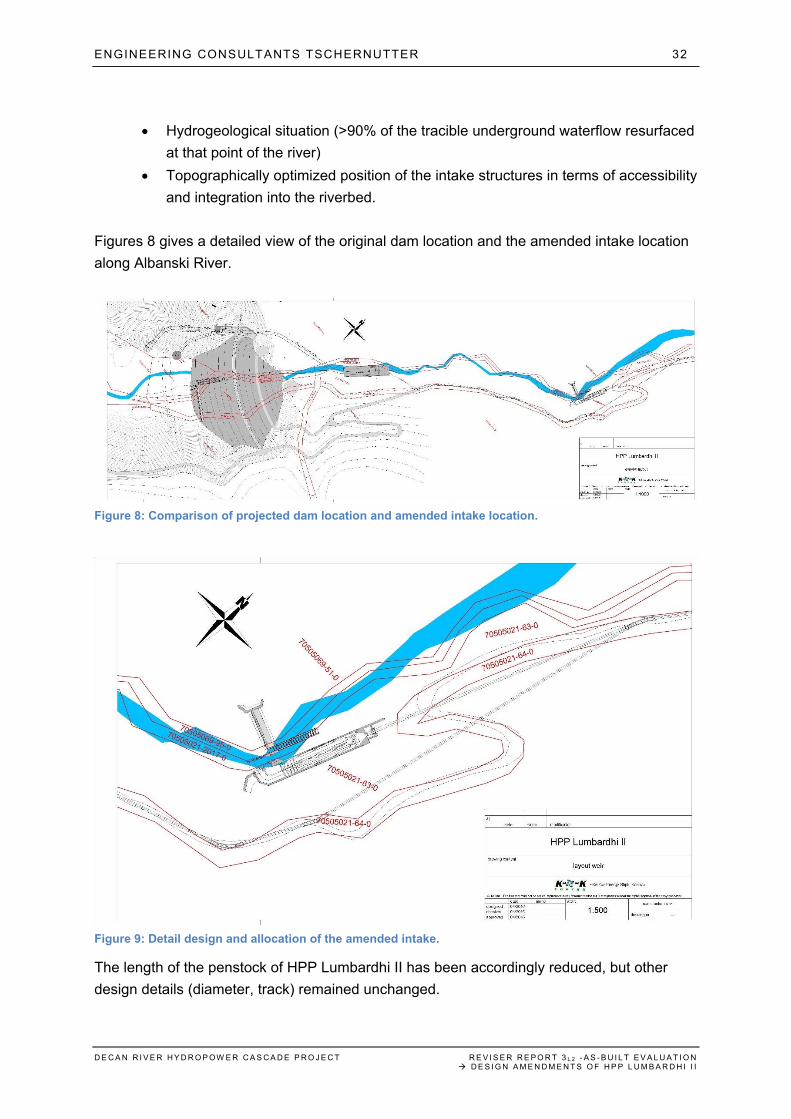
Figures 8 gives a detailed view of the original dam location and the amended intake location
along Albanski River.
Figure 8: Comparison of projected dam location and amended intake location.
Figure 9: Detail design and allocation of the amended intake.
The length of the penstock of HPP Lumbardhi II has been accordingly reduced, but other
design details (diameter, track) remained unchanged.
ENGINEERING CONSULTANTS TSCHERNUTTER 33
D E C A N R I V E R H Y D R O P O W E R C A S C A D E P R O J E C T R E V I S E R R E P O R T 3 L 2 - A S - B U I L T E V A L U A T I O N D E S I G N A M E N D M E N T S O F H P P L U M B A R D H I I I
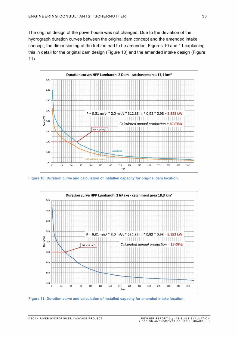
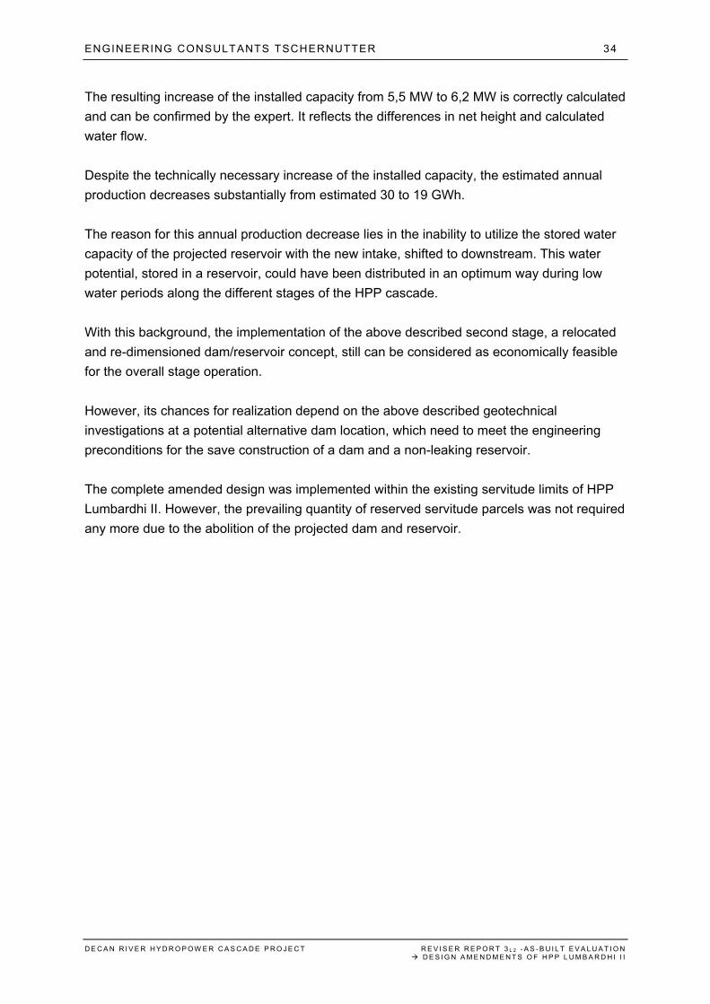
The original design of the powerhouse was not changed. Due to the deviation of the
hydrograph duration curves between the original dam concept and the amended intake
concept, the dimensioning of the turbine had to be amended. Figures 10 and 11 explaining
this in detail for the original dam design (Figure 10) and the amended intake design (Figure
11)
Figure 10: Duration curve and calculation of installed capacity for original dam location.
Figure 11: Duration curve and calculation of installed capacity for amended intake location.
ENGINEERING CONSULTANTS TSCHERNUTTER 34
D E C A N R I V E R H Y D R O P O W E R C A S C A D E P R O J E C T R E V I S E R R E P O R T 3 L 2 - A S - B U I L T E V A L U A T I O N D E S I G N A M E N D M E N T S O F H P P L U M B A R D H I I I
The resulting increase of the installed capacity from 5,5 MW to 6,2 MW is correctly calculated
and can be confirmed by the expert. It reflects the differences in net height and calculated
water flow.
Despite the technically necessary increase of the installed capacity, the estimated annual
production decreases substantially from estimated 30 to 19 GWh.
The reason for this annual production decrease lies in the inability to utilize the stored water
capacity of the projected reservoir with the new intake, shifted to downstream. This water
potential, stored in a reservoir, could have been distributed in an optimum way during low
water periods along the different stages of the HPP cascade.
With this background, the implementation of the above described second stage, a relocated
and re-dimensioned dam/reservoir concept, still can be considered as economically feasible
for the overall stage operation.
However, its chances for realization depend on the above described geotechnical
investigations at a potential alternative dam location, which need to meet the engineering
preconditions for the save construction of a dam and a non-leaking reservoir.
The complete amended design was implemented within the existing servitude limits of HPP
Lumbardhi II. However, the prevailing quantity of reserved servitude parcels was not required
any more due to the abolition of the projected dam and reservoir.
ENGINEERING CONSULTANTS TSCHERNUTTER 35
D E C A N R I V E R H Y D R O P O W E R C A S C A D E P R O J E C T R E V I S E R R E P O R T 3 L 2 - A S - B U I L T E V A L U A T I O N D E S I G N A M E N D M E N T S O F H P P L U M B A R D H I I I
2.4 REVISER CHECK NR. 1 – PLAUSIBILITY OF THE DESIGN AMENDMENTS OF THE STAGE HPP LUMBARDHI II
2.4.1 ORIGINAL DAM/RESERVOIR DESIGN
The original design for the water intake of HPP Lumbardhi II had foreseen
A dam with a maximum of 40 m height, located at the entrance swell of Zali Rupe
A connected water reservoir with an estimated volume of 3,5-4 Mio. m3
The water intake is located in the base of the dam and is connected with the penstock, which
transfers water to the turbine of the powerhouse.
The expert confirms in this context that the overall concept of a cascade with four
hydropower plants along the Decan River valley is the most feasible for an optimal utilization
of the available water potential along the Decan River HPP cascade. This was already
assessed in the Reviser Report 2, 2012.
2.4.2 GEOTECHNICAL AND HYDROGEOLOGICAL IMPLICATIONS
The above described geotechnical and hydrogeological investigations at the projected dam
location show a number of serious obstacles for the implementation of the original design:
Lack of bedrock within the maximum depth underneath the projected dam location
Substantial underground water permeability
o At the projected location of the dam
o In the reservoir area
o Across the entrance swell of Zali Rupe
Serious and wide spread inhomogeneity of the surface layer of the projected
reservoir basement
These results of the investigation have the following consequences:
Projected dam location impossible due to a lack of constructive stability
o Due to geotechnical reasons (lack of bedrock)
o Due to hydrogeological reasons (high water permeability of the basement)
Projected reservoir location impossible near the dam due to hydrogeological
reasons (high permeability of the basement)
Projected reservoir location impossible for unprepared use due to inhomogeneity
of the surface layer
ENGINEERING CONSULTANTS TSCHERNUTTER 36
D E C A N R I V E R H Y D R O P O W E R C A S C A D E P R O J E C T R E V I S E R R E P O R T 3 L 2 - A S - B U I L T E V A L U A T I O N D E S I G N A M E N D M E N T S O F H P P L U M B A R D H I I I
Considering these background conditions KelKos Energy decided to abandon the original
dam/reservoir design at the prospective location due to unsurmountable technical and
engineering obstacles.
This was from the expert´s point of view a correct decision.
2.4.3 AMENDED INTAKE DESIGN
Consequently, KelKos Energy was forced to amend the intake design of HPP Lumbardhi II to
such an extent that
The above described technical obstacles were avoided
The calculated water potential of the catchment area of HPP Lumbardhi II can be
utilized in the optimum way
From the expert point of view, the selected re-design with a classic intake structure, located
in such distance from the entrance swell of Zali Rupe, where the predominant part of the
underground water had surfaced again, was the only logic and feasible solution.
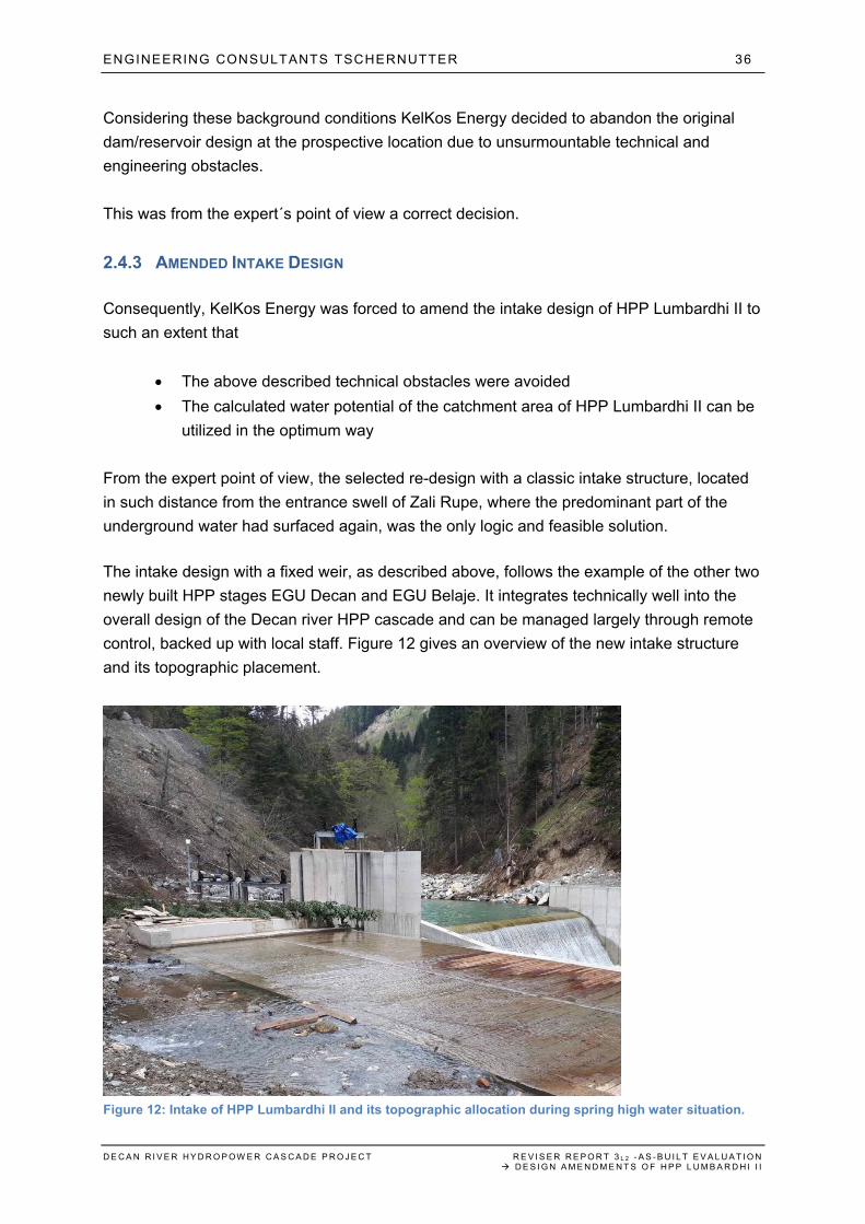
The intake design with a fixed weir, as described above, follows the example of the other two
newly built HPP stages EGU Decan and EGU Belaje. It integrates technically well into the
overall design of the Decan river HPP cascade and can be managed largely through remote
control, backed up with local staff. Figure 12 gives an overview of the new intake structure
and its topographic placement.
Figure 12: Intake of HPP Lumbardhi II and its topographic allocation during spring high water situation.
ENGINEERING CONSULTANTS TSCHERNUTTER 37
D E C A N R I V E R H Y D R O P O W E R C A S C A D E P R O J E C T R E V I S E R R E P O R T 3 L 2 - A S - B U I L T E V A L U A T I O N D E S I G N A M E N D M E N T S O F H P P L U M B A R D H I I I
2.4.4 CHANGE OF INSTALLED CAPACITY
As described in point 2.3.5, the changed and adapted parameters as well as the difference in
the calculated average water flow required a recalculation of the installed capacity of the
turbine of HPP Lumbardhi II. The related formulas for the original dam design and the
amended intake design are displayed in Figures 10 and 11.
From the expert point of view this recalculation was inevitable in order to ensure an efficient
stage operation under the changed water inflow conditions.
The formulas are correct.
The dimensioning of the turbine must follow the hydrogeological requirements and has been
correctly fixed with 6,2 MW.
2.4.5 CHANGE IN ANNUAL PRODUCTION
As displayed in Figures 10 and 11, the changed intake design has a substantial negative
effect on the estimated annual production. Instead of estimated 30 GWh of annual energy
production with the original dam/reservoir concept, largely benefiting from the additional
reservoir capacity, which can be utilized in the most efficient way over the year, the amended
intake design will not surpass 19 GWh of annual energy production under normal weather
conditions.
The related calculations are current and can be confirmed from the expert point of view.
Without question, the amended intake design is an economic disadvantage for KelKos
Energy.
Therefore, the above described investigation for an alternative dam location (stage 2) are in
the investor’s interest and should serve as basis for a final stage design decision after the
necessary investigation period of estimated 2-2,5 years.
2.4.6 CONSEQUENCES FOR THE DECAN RIVER HPP CASCADE OPERATION
The original dam/reservoir design would have been a substantial benefit for the cascade
operation along Decan River. With an estimated annual water reserve from the reservoir of
about 6-7 Mio. m3, the cascade operations could have been optimized especially during low
water periods (late summer, winter) and additional water could have been evenly distributed
across the four stages.
In addition, the stored water reserve would have been highly beneficial for the minimal water
management along the cascade.
ENGINEERING CONSULTANTS TSCHERNUTTER 38
D E C A N R I V E R H Y D R O P O W E R C A S C A D E P R O J E C T R E V I S E R R E P O R T 3 L 2 - A S - B U I L T E V A L U A T I O N D E S I G N A M E N D M E N T S O F H P P L U M B A R D H I I I
2.4.7 CONCLUSION OF THE REVISER
The original design of HPP Lumbardhi II has been approved from the expert point of view
through a Reviser Report dated 2012.
The expert assessment of the subsequent investigations and design amendments is as
following:
The above described geotechnical and hydrogeological investigations were carried
out in a professional and diligent way.
The conclusions from the investigations were correct and considerate.
A retaining on the original dam/reservoir with the background of the findings of these
investigations would have been negligent and imperiling.
The amended intake design is the best possible solution from both a hydrogeological
and engineering point of view.
The necessary recalculation of the installed capacity of the turbine of HPP Lumbardhi
II is inevitable under changed stage conditions and has been done correctly.
The calculated reduction of the estimated annual production is correct und takes into
consideration the abolition of the projected reservoir and its storage potential.
From the expert point of view this redesign procedure of the intake structure of HPP
Lumbardhi II has been conducted in a professional way.
The amended design is outright approved in all its technical aspects.
ENGINEERING CONSULTANTS TSCHERNUTTER 39
D E C A N R I V E R H Y D R O P O W E R C A S C A D E P R O J E C T R E V I S E R R E P O R T 3 L 2 - A S - B U I L T E V A L U A T I O N D E S I G N A M E N D M E N T S O F H P P L U M B A R D H I I I
2.5 REVISER CHECK NR. 2 – IMPACT ASSESSMENT OF THE AMENDED DESIGN FOR THE ENVIRONMENTAL CONDITIONS OF THE DECAN HPP STAGE
2.5.1 BASELINE ENVIRONMENTAL IMPACT CONDITIONS (EXTRACTED FROM EIA-REPORT, MARCH 2011)
2.5.1.1 EFFECTS UPON FLORA AND FAUNA, NATURAL HERITAGE AND GEOLOGY
The following scenarios, which could occur during the operational phase and which could
have a negative impact on the environment, have been assessed during the design phase of
the project and will be regularly monitored for prevention purposes.
Figure 13: Environmental impact scenarios and prevention measures during the operational phase
Impact scenario / prevention measure Prevention objective Subject of Protection
A) Instability of the reservoir embankment
Based on underground explorations and laboratory
analyses, the stability of reservoir embankments
under expected conditions will be proven
Prevention of
embankment instabilities
Human, animals and
plants, soil, water, material
properties
B) Contamination of surface water, ground water and soil
Careful handling of potentially harmful substances Prevention of
contamination
Human, animals and
plants, soil, water, air and
climate, material properties
In the powerhouses Lumbardhi and Lumbardhi II as
well as in the generation units Belaje and Decan
sufficient amounts of oil binding agents are stored to
be introduced during leakages of fuel, lubricants and
oil
Prevention of
contamination of surface
water, ground water and
soil
Human, animals and
plants, soil, water, air and
climate, material properties
Installation of oil separators and oil containment
devices inside the powerhouses and generation
units
Prevention of
contamination of surface
water, ground water and
soil
Human, animals and
plants, soil, water, air and
climate, material properties
C) Waste accumulation
Non-recyclable waste or waste with to high recycling
costs will be introduced to appropriate treatment
Treatment of non-
recyclable waste
Human, animals and
plants, soil, water, air and
climate, landscape,
material property
2.5.1.2 CHANGES OF WATER QUALITY AND QUANTITY
Emission effects from construction work regarding water-quality and related prevention and
monitoring measures are described in chapter I.7 of the EIA-Report.
During the operational phase, no such emissions will occur. Monitoring instruments and
routines will ensure the water quality throughout the entire operational period.
ENGINEERING CONSULTANTS TSCHERNUTTER 40
D E C A N R I V E R H Y D R O P O W E R C A S C A D E P R O J E C T R E V I S E R R E P O R T 3 L 2 - A S - B U I L T E V A L U A T I O N D E S I G N A M E N D M E N T S O F H P P L U M B A R D H I I I
The water quantity of Albanski and Decan river will be reduced in all river segments situated
between the respective intakes and tailrace channels.
Despite the current lack of legislative requirements, KelKos Energy has introduced into its
project design concept EU standards for residual water flow during hydropower generation.
With a residual flow of at least 20% of the average water quantity, the natural display of
Albanski and Decan River will be maintained throughout the year.
2.5.2 CONSTRUCTIVE EFFECTS OF THE AMENDED DESIGN
2.5.2.1 PENSTOCK AND POWERHOUSE
The increased installed capacity of 6,2 MW has no whatsoever effect on the constructive
dimensions of both the penstock and the powerhouse of HPP Lumbardhi II.
The technical parameters of both the turbine and the generator are amended accordingly,
without any need for constructive changes of the powerhouse building.
2.5.2.2 INTAKE VERSUS DAM/RESERVOIR
The original intake design with a combined dam and water reservoir with estimated 3,5-4
Mio. m3 volume would have had substantial environmental impact into the area of Zali Rupe.
The EIA-Report, dated March 2011, has detailed the necessary environmental precautions
and measures in order to guarantee the necessary environmental compatibility throughout
the construction and operation phase.
With the shift to a standard intake in stage 1 of the amended design, the environmental
impact during the operational phase is reduced to a fraction in comparison to the original
design. It equals the environmental conditions, which are applied for the two other stages
EGU Decan and EGU Belaje.
From the expert point of view, the amended intake design is highly favorable from the
environmental point of view throughout the construction, operation and post operation
phases.
2.5.3 EFFECTS OF THE AMENDED DESIGN ON THE FLORA AND FAUNA, NATURAL HERITAGE
AND GEOLOGY
The increased installed capacity of 6,2 MW has no whatsoever effect on the operational
parameters of the hydropower stage Lumbardhi II.
Consequently, in comparison to the original installed capacity of 5,5 MW, no additional
effects are expected on
ENGINEERING CONSULTANTS TSCHERNUTTER 41
D E C A N R I V E R H Y D R O P O W E R C A S C A D E P R O J E C T R E V I S E R R E P O R T 3 L 2 - A S - B U I L T E V A L U A T I O N D E S I G N A M E N D M E N T S O F H P P L U M B A R D H I I I
- Flora
- Fauna
- Natural Heritage
- Geology
of the HPP stage Lumbardhi II.
2.5.4 EFFECTS OF THE AMENDED DESIGN ON THE RESIDUAL FLOW OF THE HPP STAGE
According to the EIA-Report the residual flow must amount to at least 20% of the average
water quantity.
This condition remains unchanged, irrespective of the installed capacity of the hydropower
stage.
2.5.5 EFFECTS OF THE AMENDED DESIGN ON THE RECULTIVATION
The original dam design requires an adequate preparation of the basis of the related
reservoir. Excessive soil and lose gravel must be removed and the prospective basis of the
future reservoir has to be compacted to such an extent that the risk of loose particles, being
washed into the underwater intake system, are minimized.
Consequently, since 2014 the projected reservoir basis was excavated and reworked
accordingly. Excessive material was re-used for bedding material of the penstock
construction works along all three newly built stages of the Decan River HPP cascade.
According to the as-built documentation of the three stages EGU Belaje, EGU Decan and
HPP Lumbardhi II, an estimated total of 50.000.- m3 of bedding material was used for the
construction of the three individual penstocks. It divides as following:
EGU Belaje – 15.000 m3
EGU Decan – 30.000 m3
HPP Lumbardhi II – 5.000 m3
The following estimated quantities of bedding material were provided from other sources:
Excavated material from penstock track – 11.000 m3
Complementary material provided from outside Decan valley during frozen period –
4.000 m3
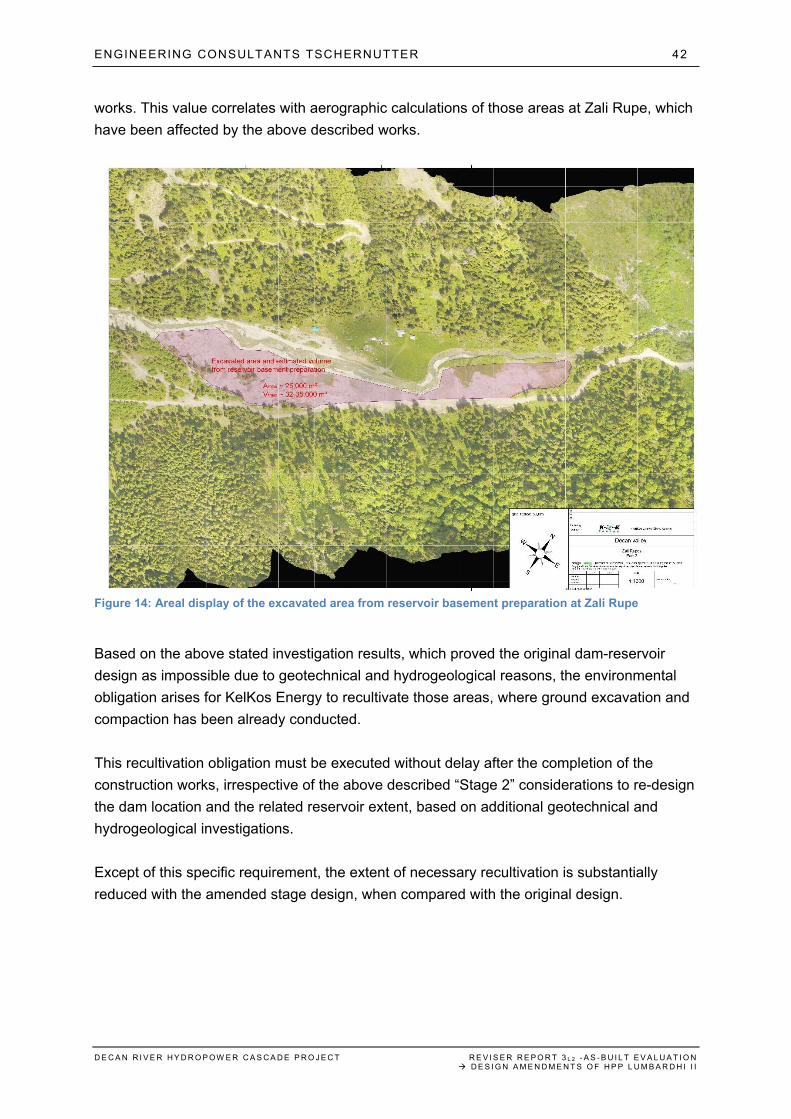
With this calculation, an estimated total of 35.000 m3 of soil and lose gravel have been
excavated from the prospective reservoir basement during the two years of preparatory
ENGINEERING CONSULTANTS TSCHERNUTTER 42
D E C A N R I V E R H Y D R O P O W E R C A S C A D E P R O J E C T R E V I S E R R E P O R T 3 L 2 - A S - B U I L T E V A L U A T I O N D E S I G N A M E N D M E N T S O F H P P L U M B A R D H I I I
works. This value correlates with aerographic calculations of those areas at Zali Rupe, which
have been affected by the above described works.
Figure 14: Areal display of the excavated area from reservoir basement preparation at Zali Rupe
Based on the above stated investigation results, which proved the original dam-reservoir
design as impossible due to geotechnical and hydrogeological reasons, the environmental
obligation arises for KelKos Energy to recultivate those areas, where ground excavation and
compaction has been already conducted.
This recultivation obligation must be executed without delay after the completion of the
construction works, irrespective of the above described “Stage 2” considerations to re-design
the dam location and the related reservoir extent, based on additional geotechnical and
hydrogeological investigations.
Except of this specific requirement, the extent of necessary recultivation is substantially
reduced with the amended stage design, when compared with the original design.
ENGINEERING CONSULTANTS TSCHERNUTTER 43
D E C A N R I V E R H Y D R O P O W E R C A S C A D E P R O J E C T R E V I S E R R E P O R T 3 L 2 - A S - B U I L T E V A L U A T I O N D E S I G N A M E N D M E N T S O F H P P L U M B A R D H I I I
2.5.6 OTHER POTENTIAL EFFECTS OF THE AMENDED DESIGN IN RELATION TO THE EIA-REPORT
From the expert point of view, no other negative environmental effects – as listed in the EIA-
Report of 2011 – are possible from the increased installed capacity of 6,2 MW.
2.5.7 CONCLUSION OF THE REVISER
The amended design, which shifts from a dam/reservoir to an intake, will have a significantly
reduced environmental impact in comparison to the original design.
From the expert point of view this design amendment causes no whatsoever negative impact
on the environmental profile of the HPP stage Lumbardhi II.
ENGINEERING CONSULTANTS TSCHERNUTTER 44
D E C A N R I V E R H Y D R O P O W E R C A S C A D E P R O J E C T R E V I S E R R E P O R T 3 L 2 - A S - B U I L T E V A L U A T I O N D E S I G N A M E N D M E N T S O F H P P L U M B A R D H I I I
2.6 CONCLUDING VERDICT OF THE REVISER KelKos Energy has requested from the undersigned experts an evaluation and plausibility check of the design amendments of HPP Lumbardhi II from dam/reservoir to intake. The undersigned have conducted an in-deep analysis of the
- On-site investigations results - Related analyses, safety considerations and consequences of KelKos Energy - Considerations and calculations for the necessary re-design of the intake system - Detail design of the amended intake system - As-built documentation of HPP Lumbardhi - On-site situation of the completed facilities construction
They come to the following concluding verdict: 1. Based on the geotechnical and hydrogeological investigation results, the implementation
of the original dam/intake design was not justifiable.
2. Neither the constructive stability of the dam, nor the hydrogeologic functionality of the reservoir could have been ensured, contradicting with this the conditions of the Construction Permit.
3. The re-design of the intake has implemented the special geotechnical and hydrogeological conditions on site in the best possible way to achieve a functional hydropower plant.
4. The formula-based re-calculation of the dimensioning of the turbine (installed capacity) was done in a correct way. For a fully functional powerplant operation the increase from 5,5 MW to 6,2 MW was inevitable.
5. The substantial decrease of the estimated annual production from 30 GWh to 19 GWh has been calculated correctly. It derives from the fact that an estimated 6-7 Mio. m3 of additional water potential are missing for distributed energy production along the stage due to the elimination of the reservoir.
6. The omission of the reservoir implies a drawback for the overall efficiency and energy output of the Decan River hydropower plant cascade. The undersigned experts recommend therefore follow-up geotechnical and hydrogeological investigations at an alternative dam location in the center of Zali Rupe. After the necessary investigation period of 2-2,5 years, a final decision should be possible whether an alternative location might be feasible for a reservoir.
Univ. Prof. Dr. techn. Peter Tschernutter
Dipl.-Ing. Milan Mulley Civil Engineer Michael Adunka
Univ. Prof. Dipl.-Ing. Dr techn. Peter Tschernutter, Reviser
Engineering Consultants Tschernutter


![Workshop Hydropower and Fish.pptx [Schreibgeschützt] - Workshop Hydropower and Fish... · Workshop Hydropower and Fish Existing hydropower facilities: ... spawning grounds and shelter](https://img.pdfslide.net/doc/110x75/5a8733247f8b9afc5d8da3c5/workshop-hydropower-and-fishpptx-schreibgeschtzt-workshop-hydropower-and-fishworkshop.jpg)