Embed Size (px)
Citation preview
Hypersonic Technology Status and Development Roadmap
Presentation to AIAA HyTASP Program Committee
December 18, 2003
Dr. Kevin G. Bowcutt TFAB #1 Chairman
Technical Fellowship Advisory Board Study
Briefing Outline
• Study Objectives, Scope and Approach
• Hypersonic Technology Assessment
• Technology Findings, Recommendations and Roadmaps
• Overall Findings and Recommendations
Technology 1 4 7 10 12 15
Structures/TPS Component & Isolated Tank ValidationsMid -Scale Structure/TPS with Conformal H2 Tanks
Mach 3-7 Small-Scale -Warm StructuresHydrocarbon & H2 TanksAblative TPS
Mach 3-14 Larger -Scale Hydrogen TanksIntegrated TPS / Structure
Mach 3-14 Near Full-Scale Integral Hydrogen Tanks Payload Attach/Release
~30 Ft VehicleICBM Boosted, Multiple Data Points
After Reentry, Reusable
2 3 65 8 9 1 1 141 3 162004
Annual $M 55 80 110 120 7 5 100 75225125 125
Validate Integrated Large-Scale Structural Assembly
($50M)
($100M)
~100 Ft VehicleTurbine To Mach 3- 4
Fully Reusable
($100M)
($200M)
($40M)
($100M)
($1.7B)*
($220M)*
($100M)*
Design
Critical Detail Tests
Fab
Ground Tests
PDR CDR Fab FlightTest
Flight Test
SRR& CoDR
Design
Critical Comp Ground Tests
Fabrication
Ground Test
• X-43A, Hyper -X• Single Engine Demo• X-43C
($500M)
Integrated Airframe Structures & Cryogenic Tanks Development Roadmap
Fundamental High Temperature Materials ResearchManufacturing Technology Development
Reactivate/Modify Ground Test Facilities
Validate High Temp Materials & Structures Using Ground Test
Boundary layer heating, thermal protection systems, sealants, coatings, and chemistry, etc.
Structural concepts, tooling, fabrication concepts, assembly concepts,
• AFRL Carbon -lamp heating component test fac .• NASA Dryden high temperature component test facility restoration• NASA Langley COLTS facility upgraded to hypersonic temps
Panel Level Tests
Coupon Tests
Design
Ground Tests
Fabrication
Fabrication
Ground Tests
PDR CDRSRR
* Includes integrated airframe, cryogenic tanks and TPS
Flight Demonstration
Backup Cost DataFlight Demonstrations
Small Scale Mid Scale Near Full Scale
(Propulsion)
Scale(Rationale)
Speed Range
Vehicle/Demo Attributes
Test Objectives
Schedule
Mach 3~4-7 Mach 3~4 -14 Mach 0-14
• 1/10 cruiser or space access vehicle
• Full- scale missile demo
• 6- 10 vehicles tested at different conditions
• Recoverable, not reusable• Several min. of data/flight• Actively cooled engine• Integrated VMS
• Rocket boosted to air -breathing takeover
• Single flowpath• Hydrocarbon fuel
• Characterize hypersonic environments
• Engine -airframe validation
• Airframe-TPS validation• MDO validation
• ~1/3-scale engine• Large enough for 1- 4
minutes of engine data
• Rocket boosted (ICBM class booster)
• Single/multiple flowpaths• Hydrogen fuel
• 3 vehicles, 6- 9 flight tests• Reusable• Multiple, ~1- minute tests
as vehicle decelerates• Re- entry or depressed
trajectory TBD
• First Mach 8-14 flight data• Cryogenic hydrogen;
cryotank-structures integration
• Some boundary layer transition data
• Near full- scale high speed engine• Sub- scale flight vehicle• Potential residual ops capability
• Low speed propulsion to ramjet/scramjet takeover
• Single/Multiple flowpaths• Hydrogen fuel
• Confirm boundary layer transition prediction
• Validate integrated airframe, TPS & control system
• Demo engine cycle & mode transitions, stage separation and rapid turnaround ops.
• 2 flight vehicles• Reusable (unmanned)• 1 or 2 stages, depending
upon vision vehicle concept• Horizontal takeoff• Vertical launch
1 2 3 4 5 6 7 8 9 10 11 12 13 14
Small ScaleSmall Scale
Mid ScaleMid Scale
Near Full ScaleNear Full Scale
Hypersonic Technology Development ROM Cost Estimates*
Annual Cost ($M)
Cumulative Cost ($M)
01000
2000
3000
4000
50006000
7000
8000
9000
10000
2004 2005 2006 2007 2008 2009 2010 2011 2012 2013 2014 2015 2016 2017
$M's
Cu
m
Flight DemonstrationVehicle Design & OptimizationStructures & CryotanksThermal ManagementPropulsion
Technology 2004 2005 2006 2007 2008 2009 2010 2011 2012 2013 2014 2015 2016 2017 TotalPropulsion 150 150 180 160 160 160 400 400 400 400 2560Thermal Management 75 75 75 95 95 95 65 65 25 25 690Structures & Cryotanks 55 80 110 120 75 100 125 225 125 75 1090Vehicle Design& Optimization 10 15 15 15 10 5 70Flight Demonstration 60 70 70 100 100 100 100 100 660 660 660 675 675 670 4700Total 350 390 450 490 440 460 690 790 1210 1160 660 675 675 670 9110
Technology 2004 2005 2006 2007 2008 2009 2010 2011 2012 2013 2014 2015 2016 2017Propulsion 150 300 480 640 800 960 1360 1760 2160 2560 2560 2560 2560 2560Thermal Management 75 150 225 320 415 510 575 640 665 690 690 690 690 690Structures & Cryotanks 55 135 245 365 440 540 665 890 1015 1090 1090 1090 1090 1090Vehicle Design & Optimization 10 25 40 55 65 70 70 70 70 70 70 70 70 70Flight Demonstration 60 130 200 300 400 500 600 700 1360 2020 2680 3355 4030 4700Total 350 740 1190 1680 2120 2580 3270 4060 5270 6430 7090 7765 8440 9110
* Engineering estimates only Boeing Limited
Hypersonic Technology Development Roadmap
Technology 1 4 7 10 12 15
Annual $M *
2 3 65 8 9 11 1413 16
2004
Propulsion
Thermal Management
Structures & Materials
Vehicle Design & Optimization
OtherMissionApplications
Space AccessFlight Demonstrations
Small Scale HC DemoSmall Scale HC Demo
Mid Scale H2 DemoMid Scale H2 Demo
Near Full Scale H2 DemoNear Full Scale H2 Demo
Small-Scale Engine Ground Test
Mid-Scale Engine Freejet Test
Near Full-Scale Engine Ground Test
High Mach Turbine Ground Test
Boundary Layer Transition Flight Test
Ultra High Temp Passive TPS
Actively Cooled TPS TMS/TPS Components
HC Hypersonic Missile
TPS/Structures Integration
TPS/Hot Structures Conformal H2 Tanks
Component Ground Tests Validate Horizontal Launch Capability With Conformal H2 Tanks
Simulation-Derived MDO Objective Functions
Complete MDO System Full Mission Simulation
SimulationManufacturing
Ground/ Flight Ops
Automated Data Flow Cost Model
Parametric OML/Layout
X-43B HC Flight Demo HC Hypersonic Cruise, Intercept, Global Strike
H2 Space Access Vehicle
350 390 450 490 440 460 690 790 1210 1160 660 675 670675 9,110
*Note: Annual $M does not include Other Mission Applications
Potential Residual CAV Launch Capability
Atmospheric Research
Business Plan
Team Selection
Tools & Procedures
• Management Briefings
• Customer Briefings
• Lessons-Learned
• TFAB Guidebook
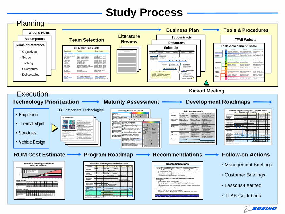
Study ProcessPlanning
Execution
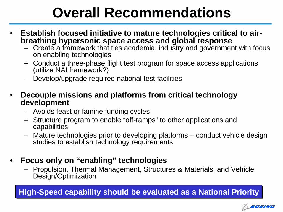
• Establish focused initiative to mature technologies critical to air-breathing hypersonic space access and global response
– Create a framework that ties academia, industry and government with focus on enabling technologies
– Conduct a three-phase flight test program for space access applications (utilize NAI framework?)
– Develop/upgrade required national test facilities
• Decouple missions and platforms from critical technology development
– Avoids feast or famine funding cycles– Structure program to enable “off-ramps” to other applications and
capabilities– Mature technologies prior to developing platforms – conduct vehicle design
studies to establish technology requirements
• Focus only on “enabling” technologies– Propulsion, Thermal Management, Structures & Materials, and Vehicle
Design/Optimization
Recommendations
High-Speed capability should be evaluated as a National PriorityHigh-Speed capability should be evaluated as a National Priority
Ground Rules
Assumptions
Terms of Reference
• Objectives
• Scope
• Tasking
• Customers
• Deliverables
Literature Review
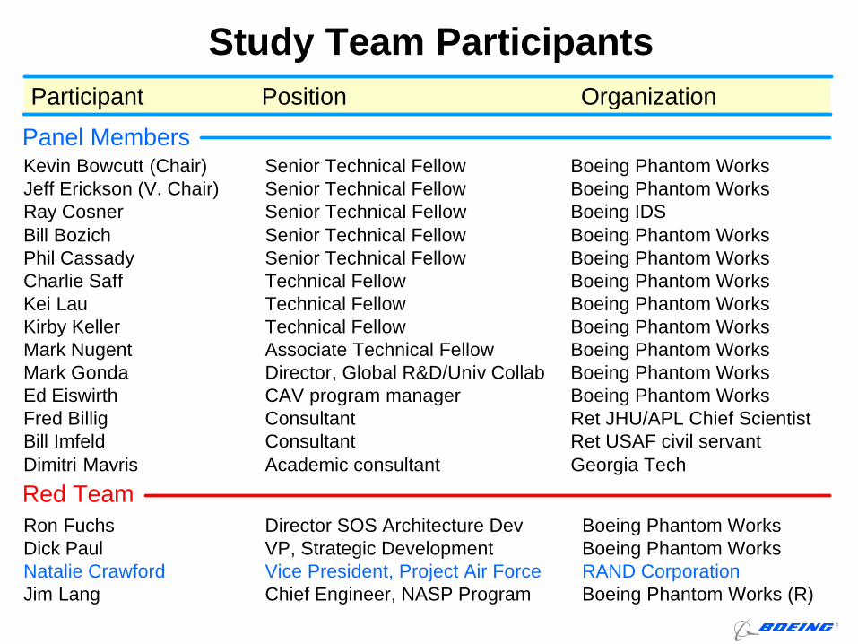
Study Team Participants
Kevin Bowcutt (Chair) Senior Technical Fellow Boeing Phantom WorksJeff Erickson (V. Chair) Senior Technical Fellow Boeing Phantom WorksRay Cosner Senior Technical Fellow Boeing IDSBill Bozich Senior Technical Fellow Boeing Phantom WorksPhil Cassady Senior Technical Fellow Boeing Phantom WorksCharlie Saff Technical Fellow Boeing Phantom WorksKei Lau Technical Fellow Boeing Phantom WorksKirby Keller Technical Fellow Boeing Phantom WorksMark Nugent Associate Technical Fellow Boeing Phantom WorksMark Gonda Director, Global R&D/Univ Collab Boeing Phantom WorksEd Eiswirth CAV program manager Boeing Phantom WorksFred Billig Consultant Ret JHU/APL Chief ScientistBill Imfeld Consultant Ret USAF civil servantDimitri Mavris Academic consultant Georgia Tech
Position OrganizationParticipant
Ron Fuchs Director SOS Architecture Dev Boeing Phantom WorksDick Paul VP, Strategic Development Boeing Phantom WorksNatalie Crawford Vice President, Project Air Force RAND CorporationJim Lang Chief Engineer, NASP Program Boeing Phantom Works (R)
Panel Members
Red Team
Subcontracts
Resources
November December January February March
Kickoff Meeting• Work Assignments
• Study Schedule• Initial Briefings
Interim Review
Final Review
• TOR & Study Plan• Literature Review• Team Coordination• Customer Contacts
Preparation
• Red Team Critique• Feedback/Adjustments• Final Assignments• Customer Contact Plan
• Management Out-brief• Deliver Products• Discuss Follow-on Tasks• Rev Customer Contact Plan
Customer Briefings
Draft Report
April
2002 2003
Dec 3 -4
Mar 27
External Review
Individual & Group Research Mar 7
• Technology Prioritization• Technology & Process Maturity Assessment• Technology Development Roadmaps• ROM Cost Estimates & Supporting rationale• Recommendations for follow-on activities
Study Deliverables
• Technical Briefings• Review of Deliverables
Meeting Jan 21 -24
Technical InterchangeTelecons
Final Report
Schedule
TFAB Website
123456789
Basic Research
ProvingFeasibility
Development
Demonstration
Validation/Verification
Implementation
TRL Product Process Analysis/Simulation
Actual System “Flight Proven” Through Successful Mission Ops.
Actual Process Proven Through Successful Operation by Program
Actual Models In Use By The Community
Actual System “Flight Qualified” Through Test & Demo
Actual Process Completed and “Qualified” Through Test/Demo
Actual Models are validated against “Flight Qualified” data
System Prototype Demonstration In an Operating Environment
Prototype Process Demo In a Program Environment
Prototype Model ValidatedAgainst Flight-Test Data
System/ Subsystem Prototype Demo In a Relevant Environment
Process Prototype Demo In a Relevant Environment
Model Validated Against Relevant Ground-Test Data
Component Validation In Relevant Environment
Beta Version Key Elements Validated In Relevant Env.
Component Validation In Laboratory Environment
Alpha Version Key Elements Validated Against Benchmark
Tools Assembled Into Package and Tested Against Hand Calcs.
Critical Function of Characteristic Proof-of-Concept.
Alpha Version Operational In a Test Environment
Data Flow Diagrams, Tools Collection and Familiarization
Technology Concept and/or Application Formulated
Requirements Document Approved By Customer
Methods and Algorithms for Similar Systems Identified
Basic Principles Observed and Reported
Current Process Documents and Potential Savings Identified
System Characterized and Tool Needs Defined
Model Components Evaluated Against Relevant Data
Tech Assessment Scale
Kickoff Meeting
Technology Prioritization Maturity Assessment Development RoadmapsTechnology Maturity Assessment
Propulsion
Thermal Management
Engine Materials ...................................Cooled Engine Panels ..........................Scramjet Combustors (Mach>7) .........Fuel Injectors/Flame Holders ..............Integrated Flowpath-Hydrocarbon ......Integrated Flowpath-Hydrogen ...........Engine Seals .........................................Engine Sensors ....................................Engine Active Control System ............TBCC Flowpath Integration .................
Hypersonic Aerothermodynamics ......Boundary Layer Transition ..................Engine Flowpath Thermal Design .......Thermal Management/Control SystemHigh/Ultra-High Temp M & S ................Actively Cooled Thermal Protection ...Durable Thermal Protection ................
11 22 33 44 55 66 77 88 99TRLCooled Metals
Cooled CMCHigh Temp
UncooledStructure
Mach>7
Mach>7
Mach>7
Mach>7
Mach>7
Mach>7
Low Maintenance High Maintenance
Technology Maturity Assessment
Structures and Materials
Vehicle Design and Optimization
Integral Metallic Cryotank ......................
Integral Composite Cryotank .................
High Temperature Metallic Structure ....High Speed (Mach 3 -7) Structures .........
Hypersonic (Mach 7-14) Structures .......Hypersonic (Mach 0-14) Structures .......
Aero-servo-elastic Structures Analysis
Parametric Geometry Generation ..........Discipline Analysis Integration ..............High Fidelity Analysis Automation ........Probabilistic Analysis .............................Multi-disciplinary Design Optimization Cost Modeling ..........................................Manufacturing Modeling .........................Operations/Campaign Modeling & SimDesign/Simulation Integration ................
11 22 33 44 55 66 77 88 99TRL
Mach 7
Al/Li Aluminum
Metal Matrix G r-EP & Gr -Bmi Composites
Advanced Metallics/Ceramics
Titanium Matrix Composite
C/C Wing Box Active & Passive
Cooling
Multi-disciplinary Analyses
Hot Structures Analysis
Hybrid Cryotanks
Integral Tank-Passive TPS
Mach 3
• Propulsion
• Thermal Mgmt
• Structures
• Vehicle Design
33 Component Technologies
Follow-on ActionsROM Cost Estimate Program Roadmap Recommendations
Engine Sensors
Technology Development Description:• Continue on-going development of shear
measurement and non-intrusive instrumentation systems.
• Apply CFD tools to develop a higher fidelity model for “Reynolds Analogy” in reacting supersonic flow to directly relate shear and heat transfer
• Demonstrate viability of advanced sensors in ground test facilities
• Demonstrate sensors, data acquisition and transmission in flight test engines
TRL Substantiation
Technology Need:Instrumentation, data acquisition and transmission capable of deducing pressure, wall temperature, heat flux and shear. Flight test vehicles require sensors capable of directing the modulation of fuel flow to maximize performance while meeting cooling requirements and preventing engine unstart. Technical Challenges:Development of robust instrumentation that is survivable in the high temperature, high heat flux environment., Capability to deduce thrust, heat transfer and mass flow with and without spillage.Technical Status: TRL = 6 for M 3-7; 3 for M 7-14Engine measurements and control has already been demonstrated in flight at Mach 4.2 (Typhon, 1962) and Mach 4.5- 5.5 ASALM (1973) and in numerous ground tests up to Mach 7-8. Sensor development for operation at M>7 has been limited to a few ground tests.Requirements for Technology Maturation:TRL 6: Development of sensors including non -intrusive diagnostics capable of functioning in high temperature high noise environment of ground test and flight.TRL 7: Flight Tests of sensor systems in sub or full scale vehicle at typical vehicle configuration that verify the functionality of the devices and design principles.
Skin Friction Gauge
PCB Transducer Kulite Transducer
Thin-Film Gage
Study Team Participants
Kevin Bowcutt (Chair) Senior Technical Fellow Boeing Phantom WorksJeff Erickson (V. Chair) Senior Technical Fellow Boeing Phantom WorksRay Cosner Senior Technical Fellow Boeing IDSBill Bozich Senior Technical Fellow Boeing Phantom WorksPhil Cassady Senior Technical Fellow Boeing Phantom WorksCharlie Saff Technical Fellow Boeing Phantom WorksKei Lau Technical Fellow Boeing Phantom WorksKirby Keller Technical Fellow Boeing Phantom WorksMark Nugent Associate Technical Fellow Boeing Phantom WorksMark Gonda Director, Global R&D/Univ Collab Boeing Phantom WorksEd Eiswirth CAV program manager Boeing Phantom WorksFred Billig Consultant Ret JHU/APL Chief ScientistBill Imfeld Consultant Ret USAF civil servantDimitri Mavris Academic consultant Georgia Tech
Position OrganizationParticipant
Ron Fuchs Director SOS Architecture Dev Boeing Phantom WorksDick Paul VP, Strategic Development Boeing Phantom WorksNatalie Crawford Vice President, Project Air Force RAND CorporationJim Lang Chief Engineer, NASP Program Boeing Phantom Works (R)
Panel Members
Red Team
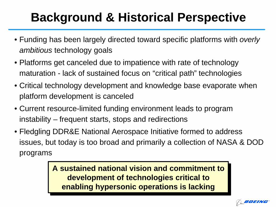
• Funding has been largely directed toward specific platforms with overly ambitious technology goals
• Platforms get canceled due to impatience with rate of technologymaturation - lack of sustained focus on “critical path” technologies
• Critical technology development and knowledge base evaporate when platform development is canceled
• Current resource-limited funding environment leads to program instability – frequent starts, stops and redirections
• Fledgling DDR&E National Aerospace Initiative formed to address issues, but today is too broad and primarily a collection of NASA & DOD programs
Background & Historical Perspective
A sustained national vision and commitment to development of technologies critical to
enabling hypersonic operations is lacking
A sustained national vision and commitment to development of technologies critical to
enabling hypersonic operations is lacking
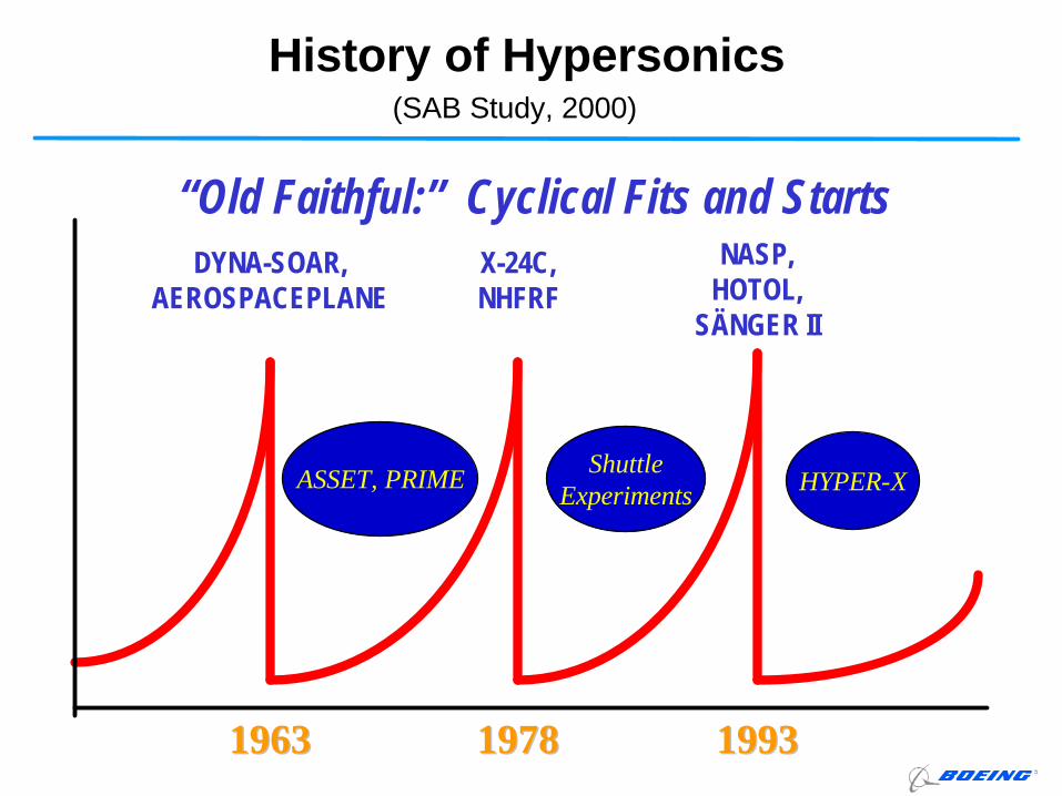
“Old Faithful:” Cyclical Fits and StartsDYNA-SOAR,
AEROSPACEPLANEX-24C, NHFRF
NASP, HOTOL,
SÄNGER II
19631963 19781978 19931993
ASSET, PRIME ShuttleExperiments HYPER-X
History of Hypersonics(SAB Study, 2000)
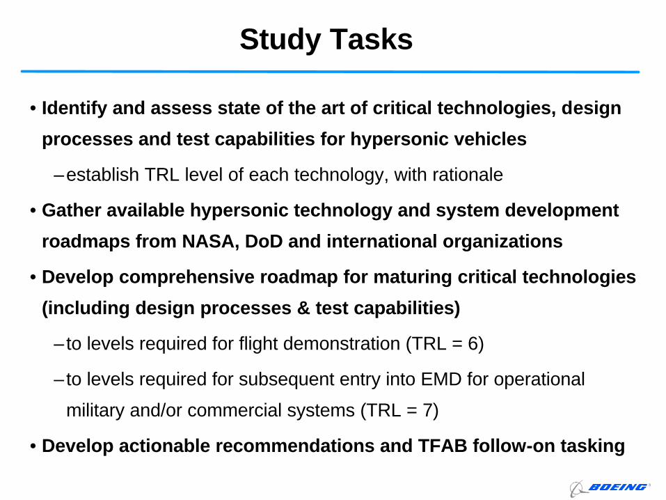
• Identify and assess state of the art of critical technologies, design
processes and test capabilities for hypersonic vehicles
–establish TRL level of each technology, with rationale
• Gather available hypersonic technology and system development
roadmaps from NASA, DoD and international organizations
• Develop comprehensive roadmap for maturing critical technologies
(including design processes & test capabilities)
–to levels required for flight demonstration (TRL = 6)
–to levels required for subsequent entry into EMD for operational
military and/or commercial systems (TRL = 7)
• Develop actionable recommendations and TFAB follow-on tasking
Study Tasks
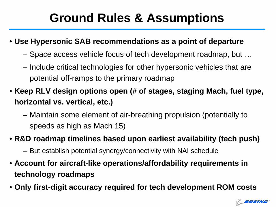
• Use Hypersonic SAB recommendations as a point of departure
– Space access vehicle focus of tech development roadmap, but …
– Include critical technologies for other hypersonic vehicles that are potential off-ramps to the primary roadmap
• Keep RLV design options open (# of stages, staging Mach, fuel type, horizontal vs. vertical, etc.)
– Maintain some element of air-breathing propulsion (potentially to speeds as high as Mach 15)
• R&D roadmap timelines based upon earliest availability (tech push)
– But establish potential synergy/connectivity with NAI schedule
• Account for aircraft-like operations/affordability requirements in technology roadmaps
• Only first-digit accuracy required for tech development ROM costs
Ground Rules & Assumptions
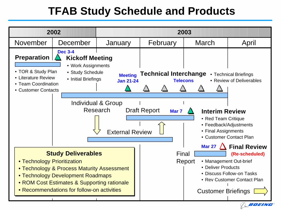
TFAB Study Schedule and Products
November December January February March
Kickoff Meeting• Work Assignments• Study Schedule• Initial Briefings
Interim Review
Final Review
• TOR & Study Plan• Literature Review• Team Coordination• Customer Contacts
Preparation
• Red Team Critique• Feedback/Adjustments• Final Assignments• Customer Contact Plan
• Management Out-brief• Deliver Products• Discuss Follow-on Tasks• Rev Customer Contact Plan
Customer Briefings
Draft Report
April
2002 2003
Dec 3-4
Mar 27
External Review
Individual & Group Research Mar 7
• Technology Prioritization• Technology & Process Maturity Assessment• Technology Development Roadmaps• ROM Cost Estimates & Supporting rationale• Recommendations for follow-on activities
Study Deliverables
• Technical Briefings• Review of Deliverables
Meeting Jan 21-24
Technical InterchangeTelecons
Final Report
(Re-scheduled)
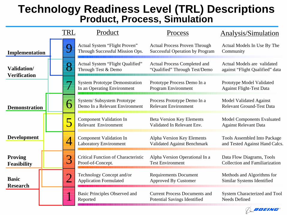
Technology Readiness Level (TRL) DescriptionsProduct, Process, Simulation
123456789
Basic Research
ProvingFeasibility
Development
Demonstration
Validation/Verification
Implementation
TRL Product Process Analysis/Simulation
Actual System “Flight Proven” Through Successful Mission Ops.
Actual Process Proven Through Successful Operation by Program
Actual Models In Use By The Community
Actual System “Flight Qualified” Through Test & Demo
Actual Process Completed and “Qualified” Through Test/Demo
Actual Models are validated against “Flight Qualified” data
System Prototype Demonstration In an Operating Environment
Prototype Process Demo In a Program Environment
Prototype Model ValidatedAgainst Flight-Test Data
System/ Subsystem Prototype Demo In a Relevant Environment
Process Prototype Demo In a Relevant Environment
Model Validated Against Relevant Ground-Test Data
Component Validation In Relevant Environment
Beta Version Key Elements Validated In Relevant Env.
Component Validation In Laboratory Environment
Alpha Version Key Elements Validated Against Benchmark
Tools Assembled Into Package and Tested Against Hand Calcs.
Critical Function of Characteristic Proof-of-Concept.
Alpha Version Operational In a Test Environment
Data Flow Diagrams, Tools Collection and Familiarization
Technology Concept and/or Application Formulated
Requirements Document Approved By Customer
Methods and Algorithms for Similar Systems Identified
Basic Principles Observed and Reported
Current Process Documents and Potential Savings Identified
System Characterized and Tool Needs Defined
Model Components Evaluated Against Relevant Data
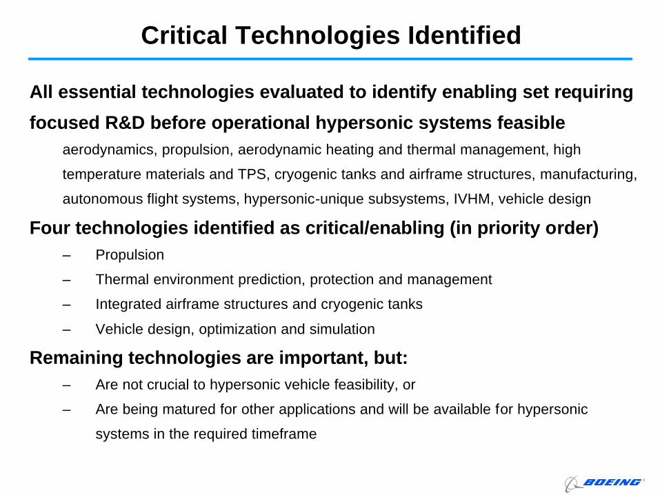
Critical Technologies Identified
All essential technologies evaluated to identify enabling set requiring
focused R&D before operational hypersonic systems feasibleaerodynamics, propulsion, aerodynamic heating and thermal management, high
temperature materials and TPS, cryogenic tanks and airframe structures, manufacturing,
autonomous flight systems, hypersonic-unique subsystems, IVHM, vehicle design
Four technologies identified as critical/enabling (in priority order)– Propulsion
– Thermal environment prediction, protection and management
– Integrated airframe structures and cryogenic tanks
– Vehicle design, optimization and simulation
Remaining technologies are important, but:– Are not crucial to hypersonic vehicle feasibility, or
– Are being matured for other applications and will be available for hypersonic
systems in the required timeframe
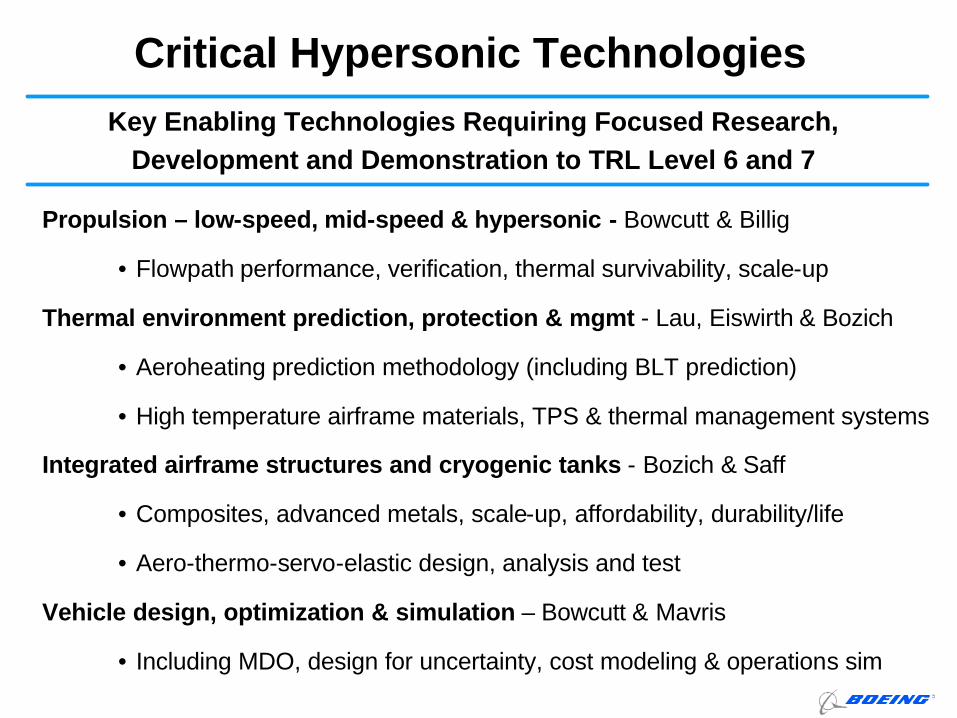
Critical Hypersonic Technologies
Propulsion – low-speed, mid-speed & hypersonic - Bowcutt & Billig
• Flowpath performance, verification, thermal survivability, scale-up
Thermal environment prediction, protection & mgmt - Lau, Eiswirth & Bozich
• Aeroheating prediction methodology (including BLT prediction)
• High temperature airframe materials, TPS & thermal management systems
Integrated airframe structures and cryogenic tanks - Bozich & Saff
• Composites, advanced metals, scale-up, affordability, durability/life
• Aero-thermo-servo-elastic design, analysis and test
Vehicle design, optimization & simulation – Bowcutt & Mavris
• Including MDO, design for uncertainty, cost modeling & operations sim
Key Enabling Technologies Requiring Focused Research, Development and Demonstration to TRL Level 6 and 7
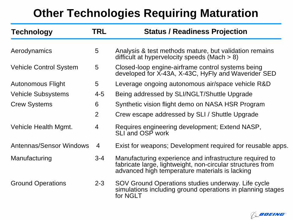
Technology
Other Technologies Requiring MaturationTRL Status / Readiness Projection
Aerodynamics 5 Analysis & test methods mature, but validation remains difficult at hypervelocity speeds (Mach > 8)
Vehicle Control System 5 Closed-loop engine-airframe control systems beingdeveloped for X-43A, X-43C, HyFly and Waverider SED
Autonomous Flight 5 Leverage ongoing autonomous air/space vehicle R&D
Vehicle Subsystems 4-5 Being addressed by SLI/NGLT/Shuttle Upgrade
Crew Systems 6 Synthetic vision flight demo on NASA HSR Program
2 Crew escape addressed by SLI / Shuttle Upgrade
Vehicle Health Mgmt. 4 Requires engineering development; Extend NASP, SLI and OSP work
Antennas/Sensor Windows 4 Exist for weapons; Development required for reusable apps.
Manufacturing 3-4 Manufacturing experience and infrastructure required to fabricate large, lightweight, non-circular structures from advanced high temperature materials is lacking
Ground Operations 2-3 SOV Ground Operations studies underway. Life cycle simulations including ground operations in planning stages for NGLT
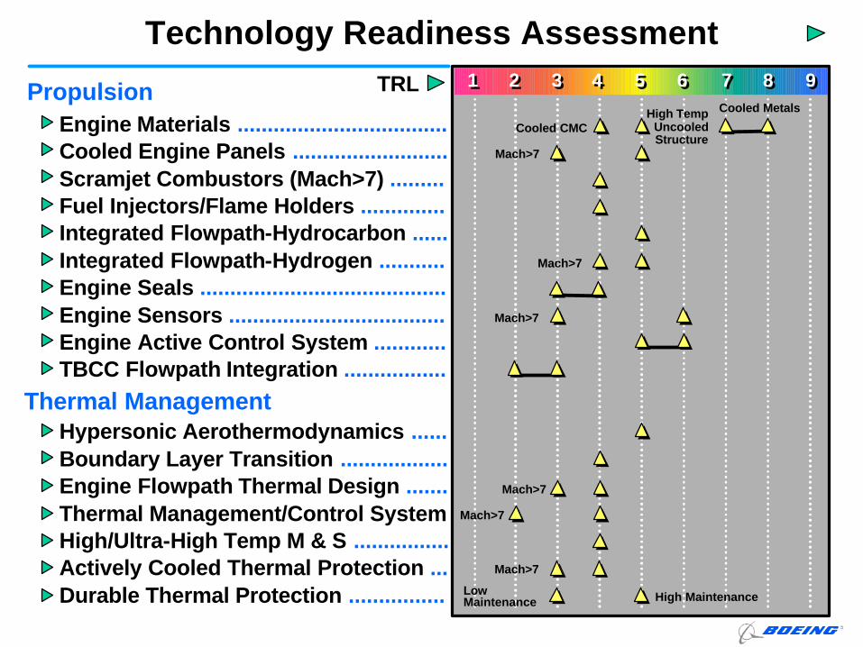
Technology Readiness Assessment
Propulsion
Thermal Management
Engine Materials ...................................Cooled Engine Panels ..........................Scramjet Combustors (Mach>7) .........Fuel Injectors/Flame Holders ..............Integrated Flowpath-Hydrocarbon ......Integrated Flowpath-Hydrogen ...........Engine Seals .........................................Engine Sensors ....................................Engine Active Control System ............TBCC Flowpath Integration .................
Hypersonic Aerothermodynamics ......Boundary Layer Transition ..................Engine Flowpath Thermal Design .......Thermal Management/Control SystemHigh/Ultra-High Temp M & S ................Actively Cooled Thermal Protection ...Durable Thermal Protection ................
11 22 33 44 55 66 77 88 99TRLCooled Metals
Cooled CMCHigh Temp
Uncooled Structure
Mach>7
Mach>7
Mach>7
Mach>7
Mach>7
Mach>7
Low Maintenance High Maintenance
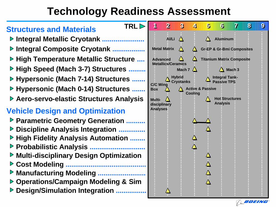
Technology Readiness Assessment
Structures and Materials
Vehicle Design and Optimization
Integral Metallic Cryotank ......................Integral Composite Cryotank .................High Temperature Metallic Structure ....High Speed (Mach 3-7) Structures .........Hypersonic (Mach 7-14) Structures .......Hypersonic (Mach 0-14) Structures .......Aero-servo-elastic Structures Analysis
Parametric Geometry Generation ..........Discipline Analysis Integration ..............High Fidelity Analysis Automation ........Probabilistic Analysis .............................Multi-disciplinary Design Optimization Cost Modeling ..........................................Manufacturing Modeling .........................Operations/Campaign Modeling & SimDesign/Simulation Integration ................
11 22 33 44 55 66 77 88 99TRL
Mach 7
Al/Li Aluminum
Metal Matrix Gr-EP & Gr-Bmi Composites
Advanced Metallics/Ceramics
Titanium Matrix Composite
C/C Wing Box Active & Passive
Cooling
Multi-disciplinary Analyses
Hot Structures Analysis
Hybrid Cryotanks
Integral Tank-Passive TPS
Mach 3
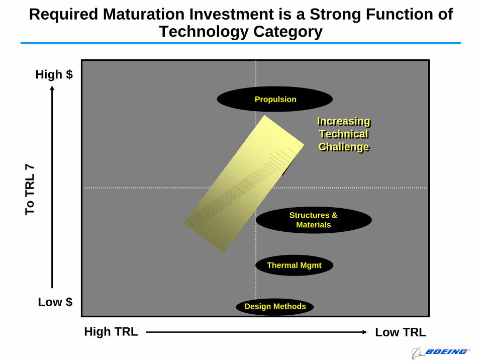
Required Maturation Investment is a Strong Function of Technology Category
High TRL Low TRL
High $
Low $
Increasing Technical Challenge
Increasing Technical Challenge
To T
RL
7
Design MethodsDesign Methods
Thermal MgmtThermal Mgmt
PropulsionPropulsion
Structures & Materials
Structures & Materials
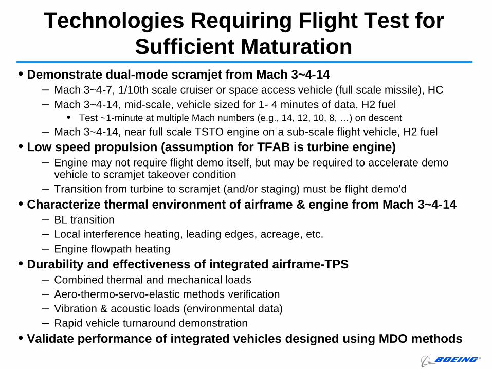
• Demonstrate dual-mode scramjet from Mach 3~4-14– Mach 3~4-7, 1/10th scale cruiser or space access vehicle (full scale missile), HC– Mach 3~4-14, mid-scale, vehicle sized for 1- 4 minutes of data, H2 fuel
• Test ~1-minute at multiple Mach numbers (e.g., 14, 12, 10, 8, …) on descent
– Mach 3~4-14, near full scale TSTO engine on a sub-scale flight vehicle, H2 fuel• Low speed propulsion (assumption for TFAB is turbine engine)
– Engine may not require flight demo itself, but may be required to accelerate demo vehicle to scramjet takeover condition
– Transition from turbine to scramjet (and/or staging) must be flight demo’d• Characterize thermal environment of airframe & engine from Mach 3~4-14
– BL transition– Local interference heating, leading edges, acreage, etc.– Engine flowpath heating
• Durability and effectiveness of integrated airframe-TPS– Combined thermal and mechanical loads– Aero-thermo-servo-elastic methods verification– Vibration & acoustic loads (environmental data)– Rapid vehicle turnaround demonstration
• Validate performance of integrated vehicles designed using MDO methods
Technologies Requiring Flight Test for Sufficient Maturation
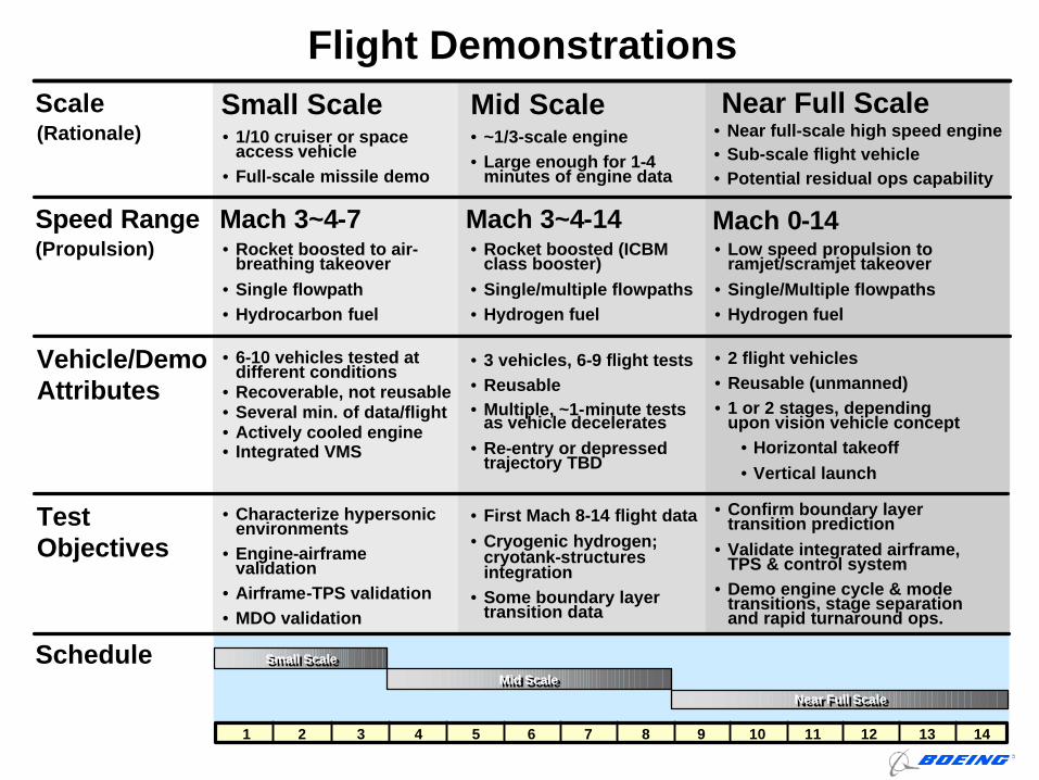
Flight DemonstrationsSmall Scale Mid Scale Near Full Scale
(Propulsion)
Scale(Rationale)
Speed Range
Vehicle/Demo Attributes
Test Objectives
Schedule
Mach 3~4-7 Mach 3~4-14 Mach 0-14
• 1/10 cruiser or space access vehicle
• Full-scale missile demo
• 6-10 vehicles tested at different conditions
• Recoverable, not reusable• Several min. of data/flight• Actively cooled engine• Integrated VMS
• Rocket boosted to air-breathing takeover
• Single flowpath• Hydrocarbon fuel
• Characterize hypersonic environments
• Engine-airframe validation
• Airframe-TPS validation• MDO validation
• ~1/3-scale engine• Large enough for 1-4
minutes of engine data
• Rocket boosted (ICBM class booster)
• Single/multiple flowpaths• Hydrogen fuel
• 3 vehicles, 6-9 flight tests• Reusable• Multiple, ~1-minute tests
as vehicle decelerates• Re-entry or depressed
trajectory TBD
• First Mach 8-14 flight data• Cryogenic hydrogen;
cryotank-structures integration
• Some boundary layer transition data
• Near full-scale high speed engine• Sub-scale flight vehicle• Potential residual ops capability
• Low speed propulsion to ramjet/scramjet takeover
• Single/Multiple flowpaths• Hydrogen fuel
• Confirm boundary layer transition prediction
• Validate integrated airframe, TPS & control system
• Demo engine cycle & mode transitions, stage separation and rapid turnaround ops.
• 2 flight vehicles• Reusable (unmanned)• 1 or 2 stages, depending
upon vision vehicle concept• Horizontal takeoff• Vertical launch
1 2 3 4 5 6 7 8 9 10 11 12 13 14
Small ScaleSmall Scale
Mid ScaleMid Scale
Near Full ScaleNear Full Scale
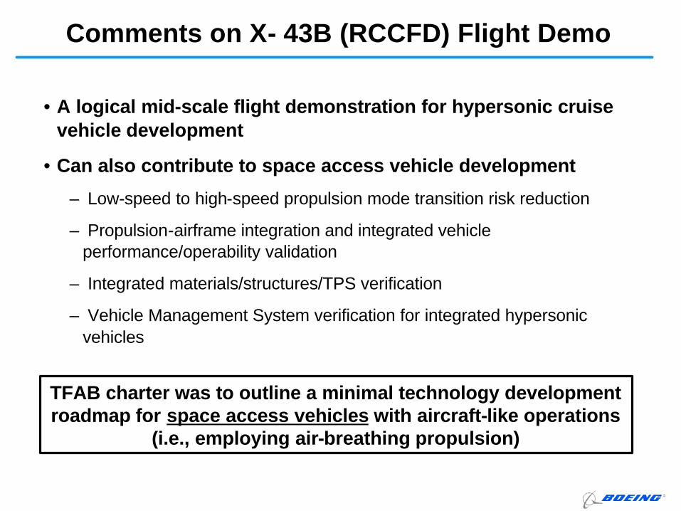
Comments on X- 43B (RCCFD) Flight Demo
• A logical mid-scale flight demonstration for hypersonic cruise vehicle development
• Can also contribute to space access vehicle development
– Low-speed to high-speed propulsion mode transition risk reduction
– Propulsion-airframe integration and integrated vehicle performance/operability validation
– Integrated materials/structures/TPS verification
– Vehicle Management System verification for integrated hypersonic vehicles
TFAB charter was to outline a minimal technology development roadmap for space access vehicles with aircraft-like operations
(i.e., employing air-breathing propulsion)
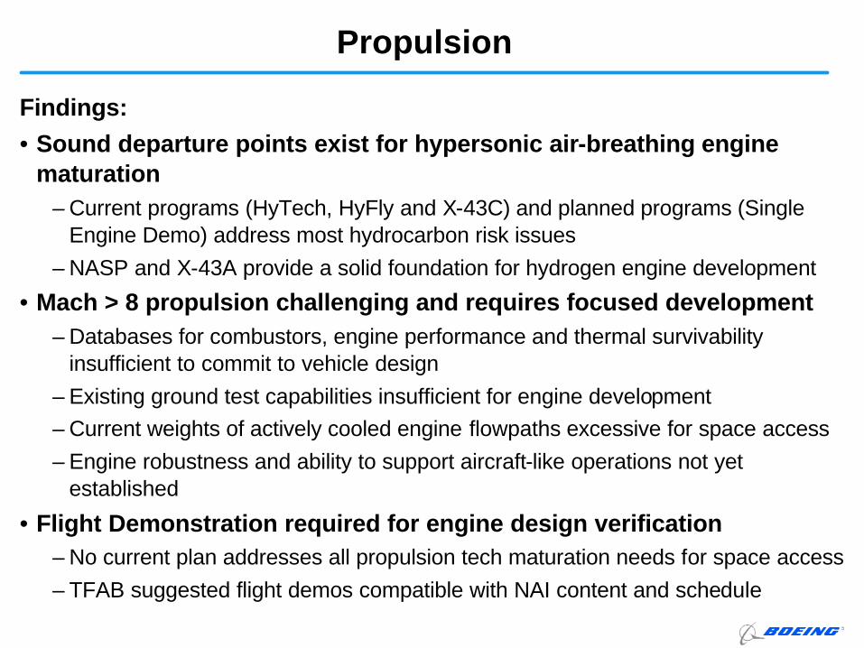
Propulsion
Findings:• Sound departure points exist for hypersonic air-breathing engine
maturation– Current programs (HyTech, HyFly and X-43C) and planned programs (Single
Engine Demo) address most hydrocarbon risk issues– NASP and X-43A provide a solid foundation for hydrogen engine development
• Mach > 8 propulsion challenging and requires focused development– Databases for combustors, engine performance and thermal survivability
insufficient to commit to vehicle design– Existing ground test capabilities insufficient for engine development– Current weights of actively cooled engine flowpaths excessive for space access– Engine robustness and ability to support aircraft-like operations not yet
established
• Flight Demonstration required for engine design verification– No current plan addresses all propulsion tech maturation needs for space access– TFAB suggested flight demos compatible with NAI content and schedule
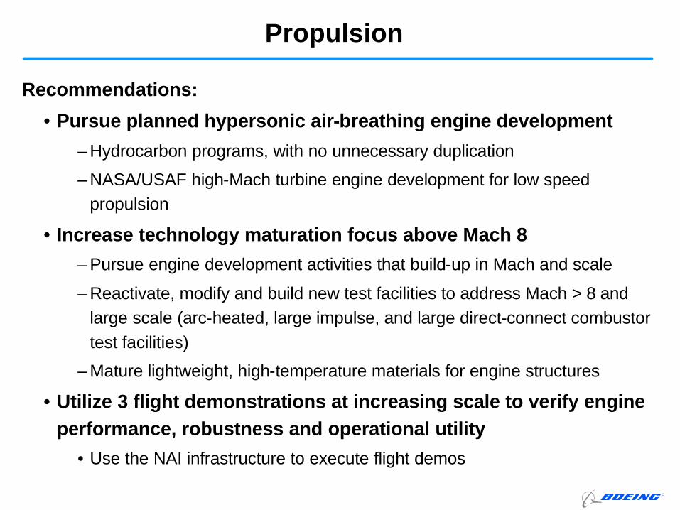
Propulsion
Recommendations:
• Pursue planned hypersonic air-breathing engine development
– Hydrocarbon programs, with no unnecessary duplication
– NASA/USAF high-Mach turbine engine development for low speed propulsion
• Increase technology maturation focus above Mach 8
– Pursue engine development activities that build-up in Mach and scale
– Reactivate, modify and build new test facilities to address Mach > 8 and large scale (arc-heated, large impulse, and large direct-connect combustor test facilities)
– Mature lightweight, high-temperature materials for engine structures
• Utilize 3 flight demonstrations at increasing scale to verify engine performance, robustness and operational utility
• Use the NAI infrastructure to execute flight demos
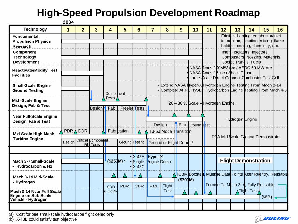
High-Speed Propulsion Development RoadmapTechnology 1 4 7 10 12 15
Small-Scale Engine Ground Testing
Fundamental Propulsion Physics ResearchComponent Technology Development
Reactivate/Modify Test Facilities
Mid -Scale Engine Design, Fab & Test
Near Full-Scale Engine Design, Fab & Test
Mach 3-7 Small-Scale - Hydrocarbon & H2
Mach 3-14 Mid-Scale - Hydrogen
Mach 3-14 Near Full-Scale Engine on Sub-Scale Vehicle - Hydrogen
Friction, heating, combustor/inlet interaction, injection, mixing, flame holding, cooling, chemistry, etc.
• Extend NASA Hyper-X Hydrogen Engine Testing From Mach 8-14• Complete AFRL HySET Hydrocarbon Engine Testing From Mach 4-8
20 – 30 % Scale – Hydrogen Engine
ICBM Boosted, Multiple Data Points After Reentry, Reusable
Inlets, Isolators, Injectors, Combustors, Nozzles, Materials, Cooled Panels, Fuels
2 3 65 8 9 11 1413 16
2004
Mid-Scale High Mach Turbine Engine
• NASA Ames 100MW Arc / AEDC 50 MW Arc• NASA Ames 16-inch Shock Tunnel• Large-Scale Direct-Connect Combustor Test Cell
Turbine To Mach 3- 4, Fully Reusable
Hydrogen Engine
($5B)
($700M)
($250M) a
Design
ComponentTests
Fab Freejet Tests
FabDesign Ground Test
PDR CDR Fab FlightTest Flight Test
SRR& CoDR
PDR DDR
Design Critical Component Rig Tests
Fabrication
Ground Testing
• X-43A, Hyper-X• Single Engine Demo• X-43C
RTA Mid-Scale Ground Demonstrator
Flight Demonstration
(a) Cost for one small-scale hydrocarbon flight demo only(b) X-43B could satisfy test objective
TJ-SJ Mode Transition
Ground or Flight Demo b
Findings:
• High uncertainty in environment prediction, including
boundary layer transition, mandates conservative TPS/TMS
design
• Vehicle-level thermal design tools are cumbersome
• Advanced all-weather, durable thermal protection materials
and components are immature (TRL<6)
• High temperature material supplier infrastructure is sparse
• Thermal management/control requirements are insufficiently
defined
Thermal Environment Prediction, Protection and Management
Recommendations:
• Form national team focused on boundary layer transition
prediction
- Conduct boundary layer transition flight experiments
- Develop physics-based prediction methods for complex geometries
- Integrate BLT prediction into CFD and design analysis
• Define focused requirements for access-to-space material and
thermal control system development
• Expand candidate material research and develop high
temperature materials database
• Design and test full-scale advanced components, e.g., tanks
with integrated TPS, leading edges, control surfaces, windows,
seals, etc.
Thermal Environment Prediction, Protection and Management
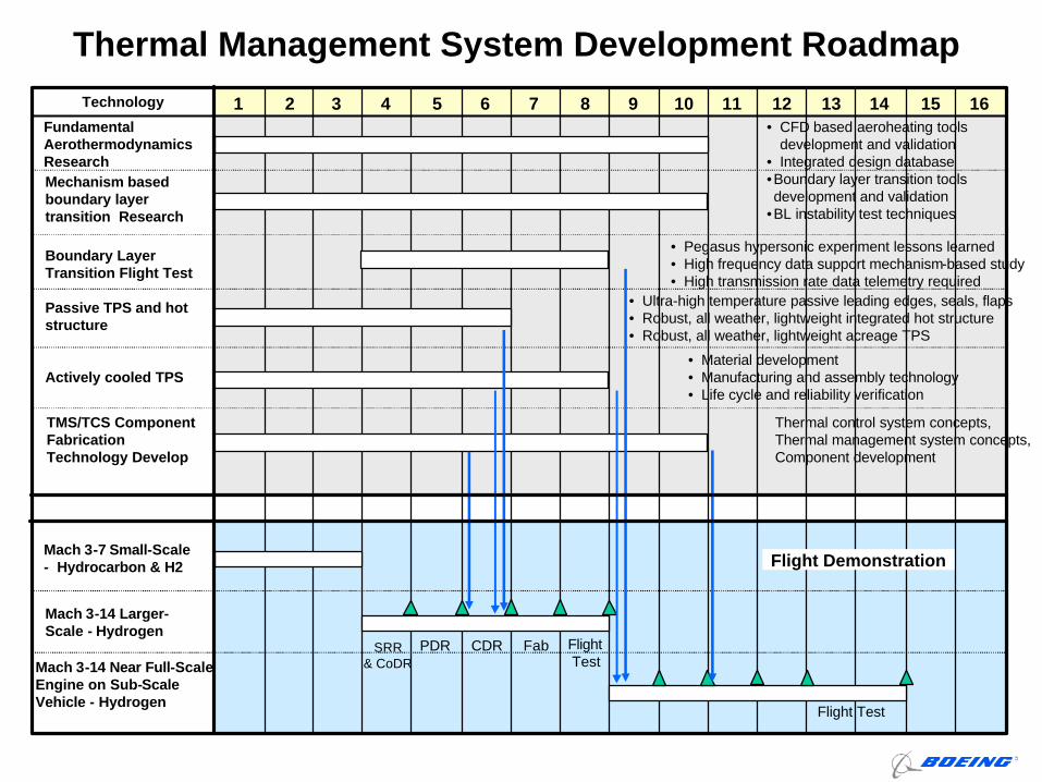
Technology 1 4 7 10 12 15Fundamental Aerothermodynamics ResearchMechanism based boundary layer transition Research
• CFD based aeroheating tools development and validation
• Integrated design database
Thermal control system concepts, Thermal management system concepts, Component development
2 3 65 8 9 11 1413 16
Mach 3-7 Small-Scale - Hydrocarbon & H2
Mach 3-14 Larger-Scale - Hydrogen
Mach 3-14 Near Full-Scale Engine on Sub-Scale Vehicle - Hydrogen
PDR CDR Fab FlightTest
Flight Test
SRR& CoDR
TMS/TCS Component Fabrication Technology Develop
•Boundary layer transition tools development and validation
•BL instability test techniques
Boundary Layer Transition Flight Test
• Pegasus hypersonic experiment lessons learned• High frequency data support mechanism-based study• High transmission rate data telemetry required
Passive TPS and hot structure
Actively cooled TPS
Thermal Management System Development Roadmap
• Ultra-high temperature passive leading edges, seals, flaps• Robust, all weather, lightweight integrated hot structure• Robust, all weather, lightweight acreage TPS
• Material development• Manufacturing and assembly technology• Life cycle and reliability verification
Flight Demonstration
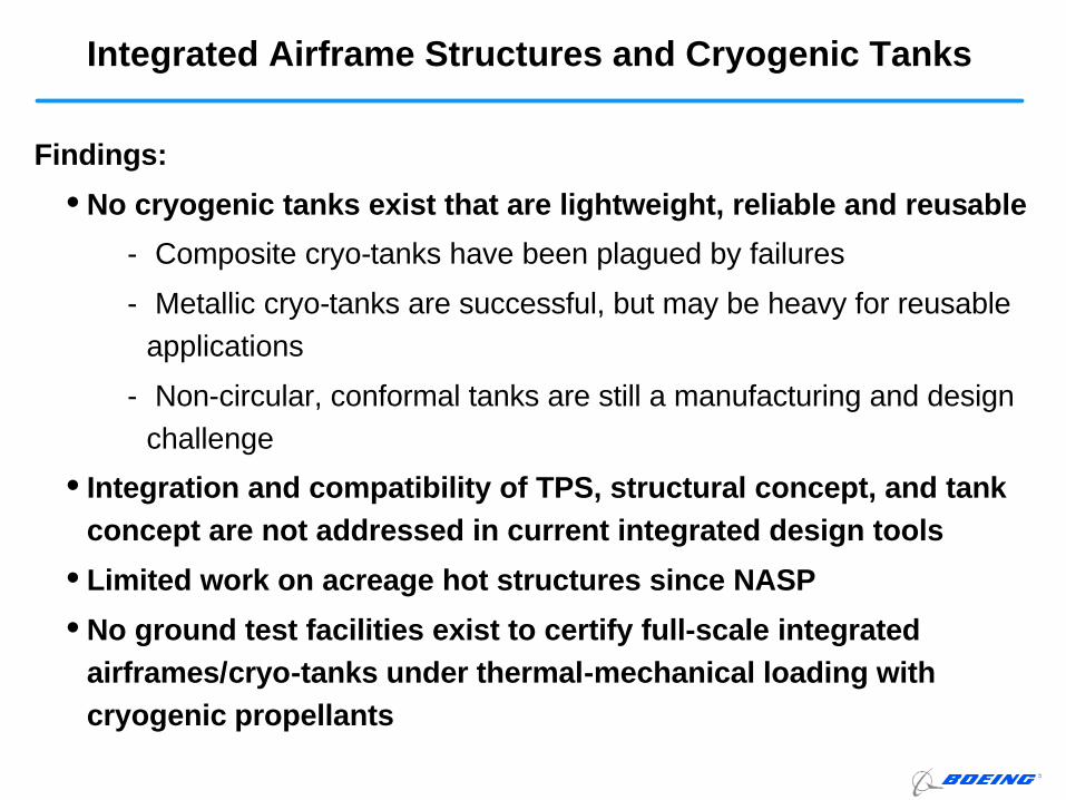
Findings:
• No cryogenic tanks exist that are lightweight, reliable and reusable
- Composite cryo-tanks have been plagued by failures
- Metallic cryo-tanks are successful, but may be heavy for reusable applications
- Non-circular, conformal tanks are still a manufacturing and design challenge
• Integration and compatibility of TPS, structural concept, and tank concept are not addressed in current integrated design tools
• Limited work on acreage hot structures since NASP
• No ground test facilities exist to certify full-scale integrated airframes/cryo-tanks under thermal-mechanical loading with cryogenic propellants
Integrated Airframe Structures and Cryogenic Tanks
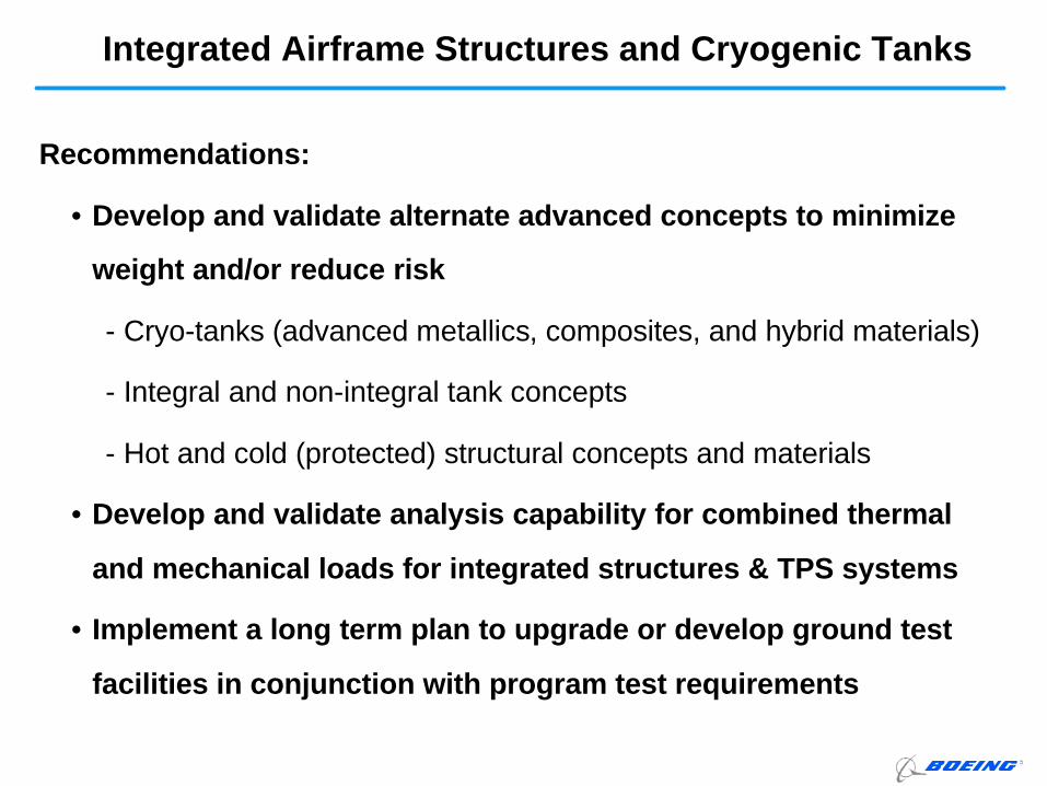
Recommendations:
• Develop and validate alternate advanced concepts to minimize
weight and/or reduce risk
- Cryo-tanks (advanced metallics, composites, and hybrid materials)
- Integral and non-integral tank concepts
- Hot and cold (protected) structural concepts and materials
• Develop and validate analysis capability for combined thermal
and mechanical loads for integrated structures & TPS systems
• Implement a long term plan to upgrade or develop ground test
facilities in conjunction with program test requirements
Integrated Airframe Structures and Cryogenic Tanks
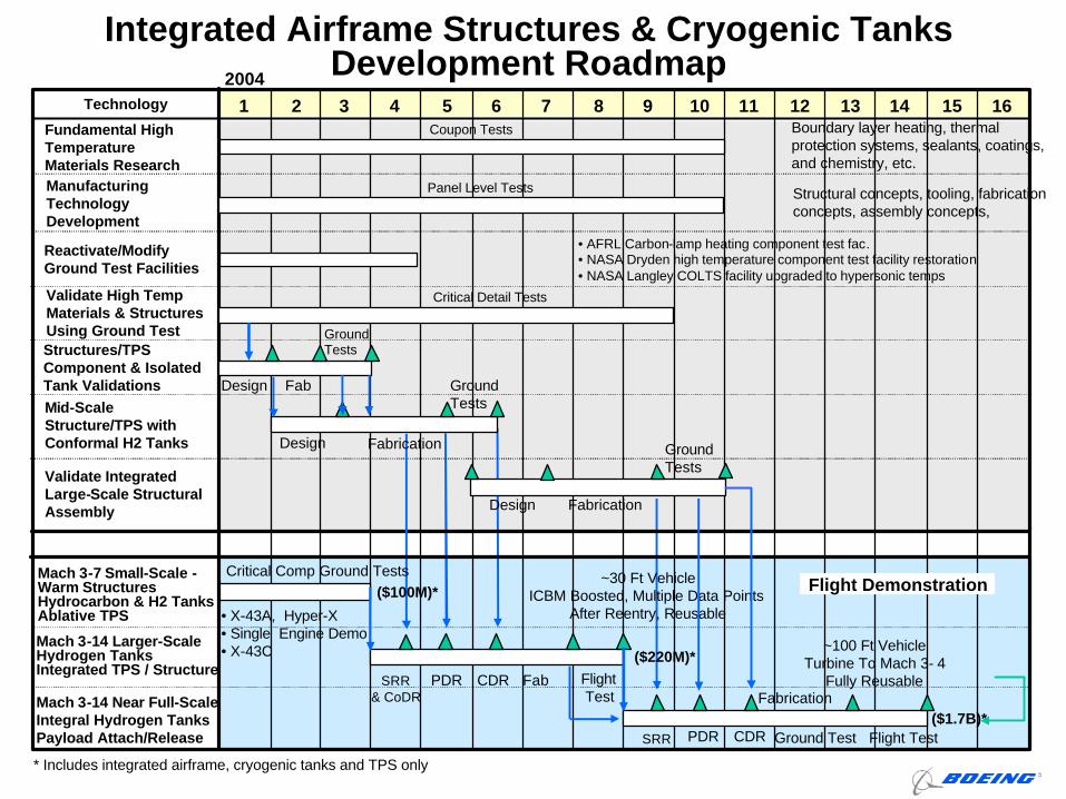
Technology 1 4 7 10 12 15
Structures/TPS Component & Isolated Tank ValidationsMid-Scale Structure/TPS with Conformal H2 Tanks
Mach 3-7 Small-Scale -Warm StructuresHydrocarbon & H2 TanksAblative TPS
Mach 3-14 Larger-Scale Hydrogen TanksIntegrated TPS / Structure
Mach 3-14 Near Full-Scale Integral Hydrogen Tanks Payload Attach/Release
~30 Ft VehicleICBM Boosted, Multiple Data Points
After Reentry, Reusable
2 3 65 8 9 11 1413 16
2004
Validate Integrated Large-Scale Structural Assembly
~100 Ft VehicleTurbine To Mach 3- 4
Fully Reusable
($1.7B)*
($220M)*
($100M)*
Design
Critical Detail Tests
Fab
Ground Tests
PDR CDR Fab FlightTest
Flight Test
SRR& CoDR
Design
Critical Comp Ground Tests
Fabrication
Ground Test
• X-43A, Hyper-X• Single Engine Demo• X-43C
Integrated Airframe Structures & Cryogenic Tanks Development Roadmap
Fundamental High Temperature Materials ResearchManufacturing Technology Development
Reactivate/Modify Ground Test Facilities
Validate High Temp Materials & Structures Using Ground Test
Boundary layer heating, thermal protection systems, sealants, coatings, and chemistry, etc.
Structural concepts, tooling, fabrication concepts, assembly concepts,
• AFRL Carbon-lamp heating component test fac.• NASA Dryden high temperature component test facility restoration• NASA Langley COLTS facility upgraded to hypersonic temps
Panel Level Tests
Coupon Tests
Design
Ground Tests
Fabrication
Fabrication
Ground Tests
PDR CDRSRR
* Includes integrated airframe, cryogenic tanks and TPS only
Flight Demonstration
Vehicle Design System
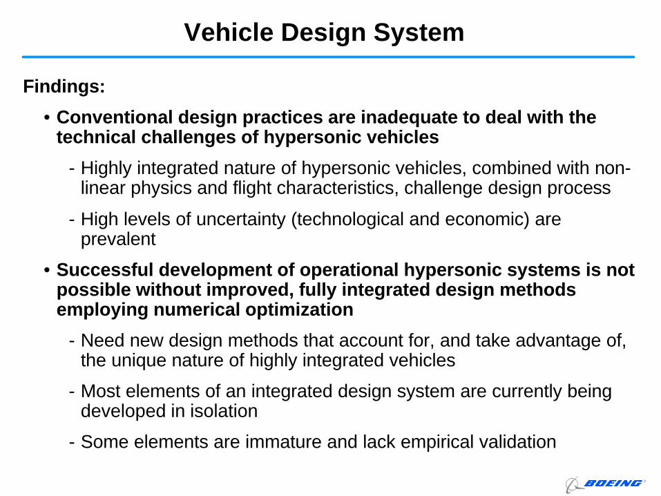
Findings:
• Conventional design practices are inadequate to deal with the technical challenges of hypersonic vehicles
- Highly integrated nature of hypersonic vehicles, combined with non-linear physics and flight characteristics, challenge design process
- High levels of uncertainty (technological and economic) are prevalent
• Successful development of operational hypersonic systems is not possible without improved, fully integrated design methods employing numerical optimization
- Need new design methods that account for, and take advantage of,the unique nature of highly integrated vehicles
- Most elements of an integrated design system are currently beingdeveloped in isolation
- Some elements are immature and lack empirical validation
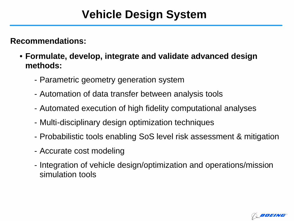
Vehicle Design System
Recommendations:
• Formulate, develop, integrate and validate advanced design methods:
- Parametric geometry generation system
- Automation of data transfer between analysis tools
- Automated execution of high fidelity computational analyses
- Multi-disciplinary design optimization techniques
- Probabilistic tools enabling SoS level risk assessment & mitigation
- Accurate cost modeling
- Integration of vehicle design/optimization and operations/mission simulation tools
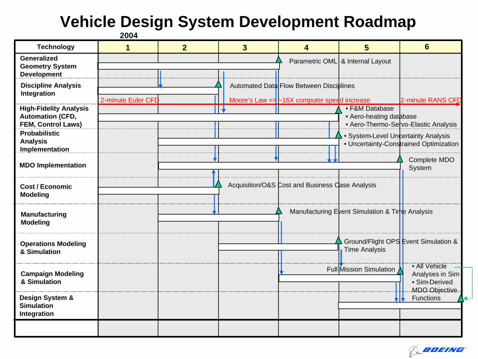
Vehicle Design System Development RoadmapTechnology 1 2 3 4 5 6
Probabilistic Analysis Implementation
Generalized Geometry System Development
Discipline Analysis Integration
High-Fidelity Analysis Automation (CFD, FEM, Control Laws)
MDO Implementation
Cost / Economic Modeling
Manufacturing Modeling
Operations Modeling & Simulation
Campaign Modeling & Simulation
Design System & Simulation Integration
Parametric OML & Internal Layout
• F&M Database• Aero-heating database• Aero-Thermo-Servo-Elastic Analysis
Complete MDO System
Acquisition/O&S Cost and Business Case Analysis
Manufacturing Event Simulation & Time Analysis
Ground/Flight OPS Event Simulation & Time Analysis
• All Vehicle Analyses in Sim• Sim-Derived MDO Objective Functions
Full Mission Simulation
Automated Data Flow Between Disciplines
• System-Level Uncertainty Analysis• Uncertainty-Constrained Optimization
2-minute Euler CFD 2-minute RANS CFDMoore’s Law => ~16X computer speed increase
2004
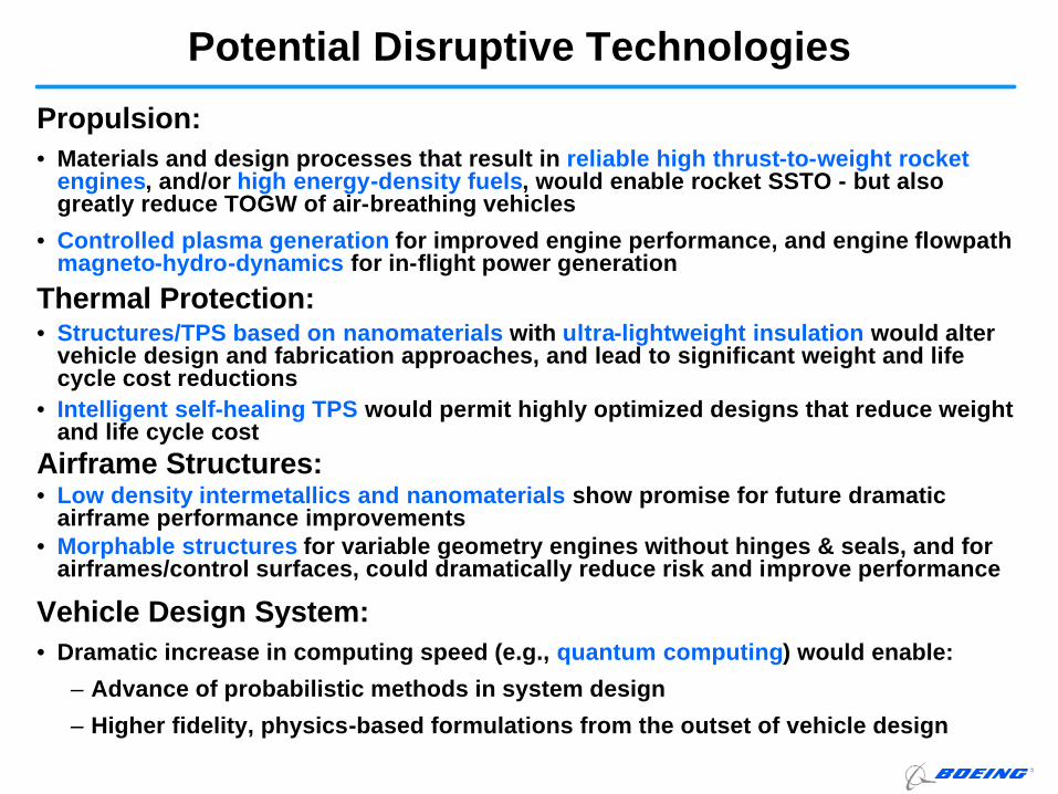
Potential Disruptive Technologies
Propulsion:• Materials and design processes that result in reliable high thrust-to-weight rocket
engines, and/or high energy-density fuels, would enable rocket SSTO - but also greatly reduce TOGW of air-breathing vehicles
• Controlled plasma generation for improved engine performance, and engine flowpathmagneto-hydro-dynamics for in-flight power generation
Thermal Protection:• Structures/TPS based on nanomaterials with ultra-lightweight insulation would alter
vehicle design and fabrication approaches, and lead to significant weight and life cycle cost reductions
• Intelligent self-healing TPS would permit highly optimized designs that reduce weight and life cycle cost
Airframe Structures:• Low density intermetallics and nanomaterials show promise for future dramatic
airframe performance improvements• Morphable structures for variable geometry engines without hinges & seals, and for
airframes/control surfaces, could dramatically reduce risk and improve performance
Vehicle Design System:• Dramatic increase in computing speed (e.g., quantum computing) would enable:
– Advance of probabilistic methods in system design
– Higher fidelity, physics-based formulations from the outset of vehicle design
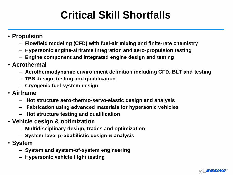
• Propulsion– Flowfield modeling (CFD) with fuel-air mixing and finite-rate chemistry– Hypersonic engine-airframe integration and aero-propulsion testing– Engine component and integrated engine design and testing
• Aerothermal– Aerothermodynamic environment definition including CFD, BLT and testing– TPS design, testing and qualification– Cryogenic fuel system design
• Airframe – Hot structure aero-thermo-servo-elastic design and analysis– Fabrication using advanced materials for hypersonic vehicles– Hot structure testing and qualification
• Vehicle design & optimization– Multidisciplinary design, trades and optimization– System-level probabilistic design & analysis
• System– System and system-of-system engineering– Hypersonic vehicle flight testing
Critical Skill Shortfalls
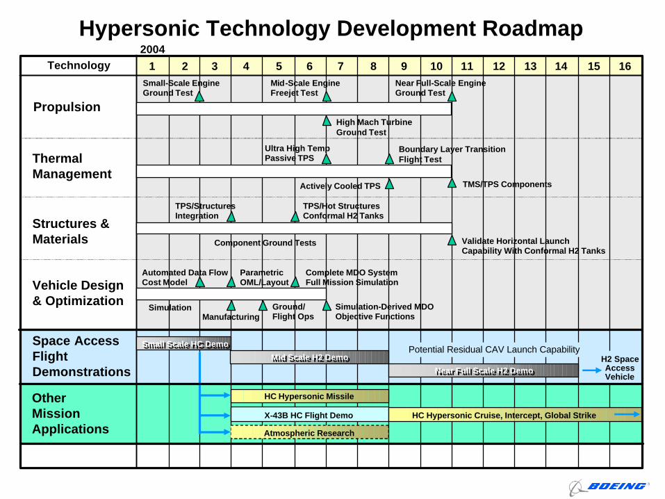
Hypersonic Technology Development RoadmapTechnology 1 4 7 10 12 152 3 65 8 9 11 1413 16
2004
Propulsion
Thermal Management
Structures & Materials
Vehicle Design & Optimization
OtherMissionApplications
Space AccessFlight Demonstrations
Small Scale HC DemoSmall Scale HC Demo
Mid Scale H2 DemoMid Scale H2 Demo
Near Full Scale H2 DemoNear Full Scale H2 Demo
Small-Scale Engine Ground Test
Mid-Scale Engine Freejet Test
Near Full-Scale Engine Ground Test
High Mach Turbine Ground Test
Boundary Layer Transition Flight Test
Ultra High Temp Passive TPS
Actively Cooled TPS TMS/TPS Components
HC Hypersonic Missile
TPS/Structures Integration
TPS/Hot Structures Conformal H2 Tanks
Component Ground Tests Validate Horizontal Launch Capability With Conformal H2 Tanks
Simulation-Derived MDO Objective Functions
Complete MDO System Full Mission Simulation
SimulationManufacturing
Ground/ Flight Ops
Automated Data Flow Cost Model
Parametric OML/Layout
X-43B HC Flight Demo HC Hypersonic Cruise, Intercept, Global Strike
H2 Space Access Vehicle
Potential Residual CAV Launch Capability
Atmospheric Research
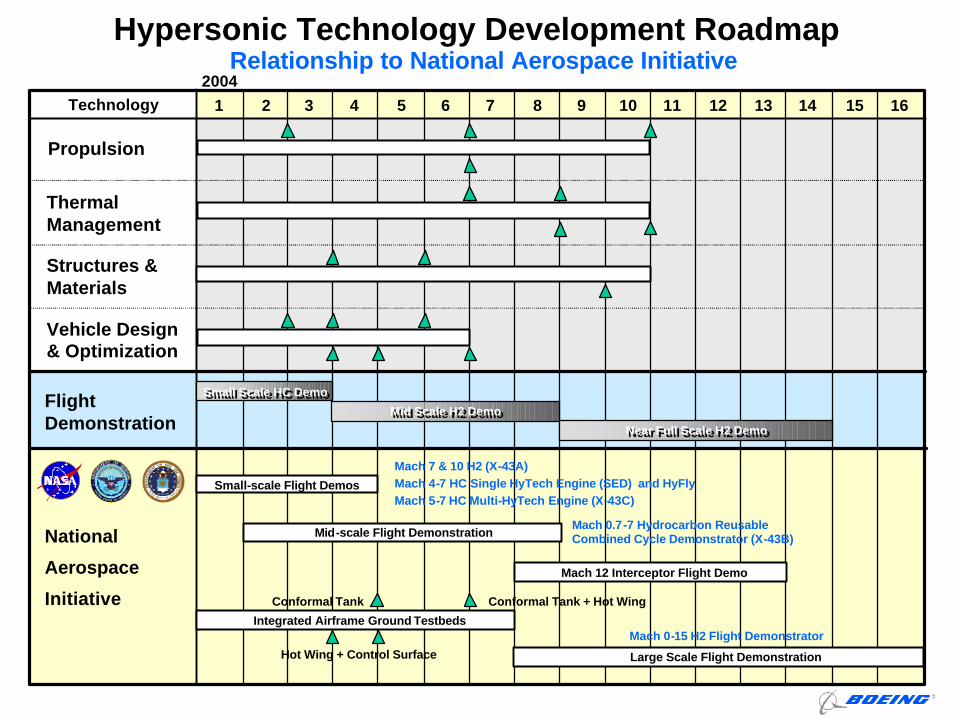
Hypersonic Technology Development Roadmap
Technology 1 4 7 10 12 152 3 65 8 9 11 1413 16
2004
Thermal Management
Structures & Materials
Vehicle Design & Optimization
Flight Demonstration
Propulsion
Mid-scale Flight DemonstrationMach 0.7-7 Hydrocarbon Reusable Combined Cycle Demonstrator (X-43B)
Integrated Airframe Ground Testbeds
Conformal Tank Conformal Tank + Hot Wing
Hot Wing + Control Surface
Small-scale Flight Demos
Mach 7 & 10 H2 (X-43A)Mach 4-7 HC Single HyTech Engine (SED) and HyFlyMach 5-7 HC Multi-HyTech Engine (X-43C)
National
Aerospace
Initiative
Relationship to National Aerospace Initiative
Mach 12 Interceptor Flight Demo
Large Scale Flight Demonstration
Mach 0-15 H2 Flight Demonstrator
Small Scale HC DemoSmall Scale HC Demo
Mid Scale H2 DemoMid Scale H2 Demo
Near Full Scale H2 DemoNear Full Scale H2 Demo
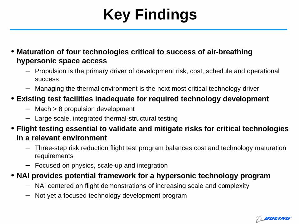
Key Findings
• Maturation of four technologies critical to success of air-breathing hypersonic space access
– Propulsion is the primary driver of development risk, cost, schedule and operational success
– Managing the thermal environment is the next most critical technology driver
• Existing test facilities inadequate for required technology development– Mach > 8 propulsion development– Large scale, integrated thermal-structural testing
• Flight testing essential to validate and mitigate risks for critical technologies in a relevant environment
– Three-step risk reduction flight test program balances cost and technology maturation requirements
– Focused on physics, scale-up and integration
• NAI provides potential framework for a hypersonic technology program– NAI centered on flight demonstrations of increasing scale and complexity– Not yet a focused technology development program
• Establish focused initiative to mature technologies critical to air-breathing hypersonic space access and global response– Create a framework that ties academia, industry and government with focus
on enabling technologies– Conduct a three-phase flight test program for space access applications
(utilize NAI framework?)– Develop/upgrade required national test facilities
• Decouple missions and platforms from critical technology development– Avoids feast or famine funding cycles– Structure program to enable “off-ramps” to other applications and
capabilities– Mature technologies prior to developing platforms – conduct vehicle design
studies to establish technology requirements
• Focus only on “enabling” technologies– Propulsion, Thermal Management, Structures & Materials, and Vehicle
Design/Optimization
Overall Recommendations
High-Speed capability should be evaluated as a National PriorityHigh-Speed capability should be evaluated as a National Priority
Supporting Data Example: Hypersonic Propulsion
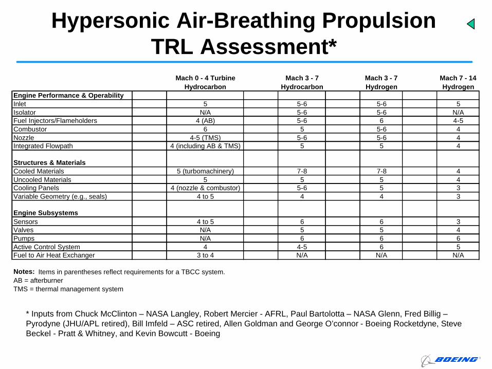
Hypersonic Air-Breathing Propulsion TRL Assessment*
* Inputs from Chuck McClinton – NASA Langley, Robert Mercier - AFRL, Paul Bartolotta – NASA Glenn, Fred Billig –Pyrodyne (JHU/APL retired), Bill Imfeld – ASC retired, Allen Goldman and George O’connor - Boeing Rocketdyne, Steve Beckel - Pratt & Whitney, and Kevin Bowcutt - Boeing
Mach 0 - 4 Turbine Hydrocarbon
Mach 3 - 7 Hydrocarbon
Mach 3 - 7 Hydrogen
Mach 7 - 14 Hydrogen
Engine Performance & OperabilityInlet 5 5-6 5-6 5Isolator N/A 5-6 5-6 N/AFuel Injectors/Flameholders 4 (AB) 5-6 6 4-5Combustor 6 5 5-6 4Nozzle 4-5 (TMS) 5-6 5-6 4Integrated Flowpath 4 (including AB & TMS) 5 5 4
Structures & MaterialsCooled Materials 5 (turbomachinery) 7-8 7-8 4Uncooled Materials 5 5 5 4Cooling Panels 4 (nozzle & combustor) 5-6 5 3Variable Geometry (e.g., seals) 4 to 5 4 4 3
Engine SubsystemsSensors 4 to 5 6 6 3Valves N/A 5 5 4Pumps N/A 6 6 6Active Control System 4 4-5 6 5Fuel to Air Heat Exchanger 3 to 4 N/A N/A N/A
Notes: Items in parentheses reflect requirements for a TBCC system.AB = afterburnerTMS = thermal management system

Boeing Supports NAI Hypersonic Flight Demonstration Programs
• Joint DoD and NASA plan to leverage Air Force HyTechprogram through a series of critical flight demonstrations– Demonstrate technologies required for first generation hypersonic vehicles– Single Engine Demonstration: Single hydrocarbon fueled scramjet engine– X-43C: Combines three Hytech engines in an aircraft-like configuration– X-43B: Combines HyTech advances with high-speed turbine to enable a
reusable x-plane in the tradition of the X-15
Will enable capabilities for responding to future time-critical threats rapidly from CONUS, and provide for reusable, cost-effective access to space
– Hypersonic missiles– Hypersonic aircraft– Air-breathing Reusable Launch Vehicles
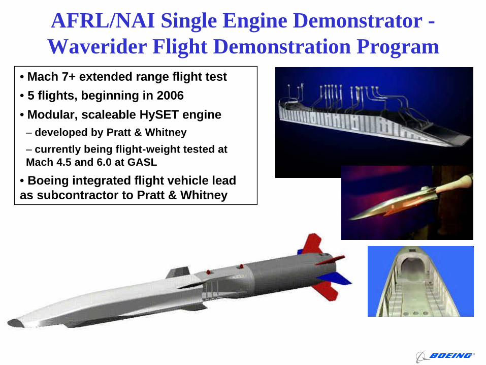
AFRL/NAI Single Engine Demonstrator -Waverider Flight Demonstration Program
• Mach 7+ extended range flight test
• 5 flights, beginning in 2006
• Modular, scaleable HySET engine– developed by Pratt & Whitney
– currently being flight-weight tested at Mach 4.5 and 6.0 at GASL
• Boeing integrated flight vehicle lead as subcontractor to Pratt & Whitney
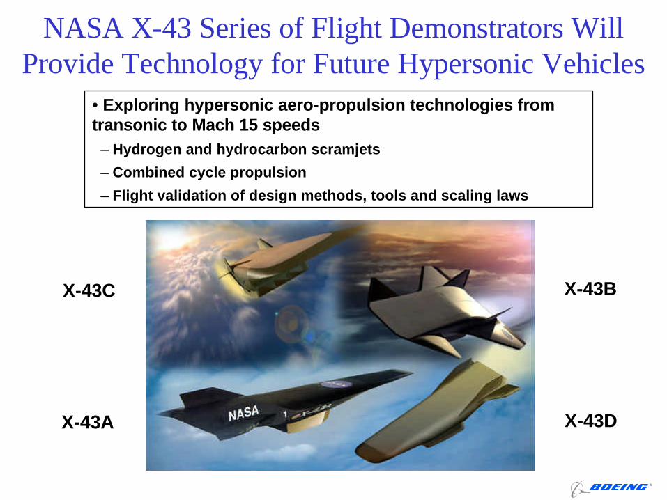
NASA X-43 Series of Flight Demonstrators Will Provide Technology for Future Hypersonic Vehicles
• Exploring hypersonic aero-propulsion technologies from transonic to Mach 15 speeds
– Hydrogen and hydrocarbon scramjets
– Combined cycle propulsion
– Flight validation of design methods, tools and scaling laws
X-43DX-43A
X-43BX-43C
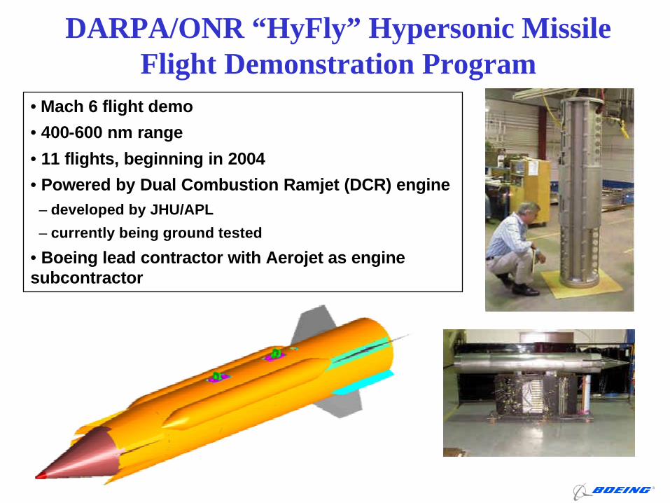
DARPA/ONR “HyFly” Hypersonic Missile Flight Demonstration Program
• Mach 6 flight demo
• 400-600 nm range
• 11 flights, beginning in 2004
• Powered by Dual Combustion Ramjet (DCR) engine– developed by JHU/APL
– currently being ground tested
• Boeing lead contractor with Aerojet as engine subcontractor
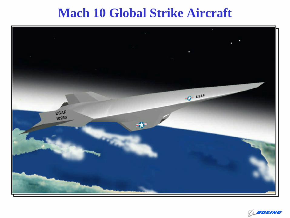
Mach 10 Global Strike Aircraft
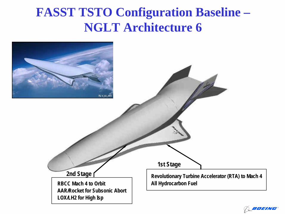
FASST TSTO Configuration Baseline –NGLT Architecture 6
RBCC Mach 4 to Orbit
LOX/LH2 for High IspAAR/Rocket for Subsonic Abort
Revolutionary Turbine Accelerator (RTA) to Mach 4All Hydrocarbon Fuel
1st Stage
2nd Stage