Embed Size (px)
Citation preview

AC-PRO-MPTM Instruction Manual www.utilityrelay.com
Manual Rev 2.0
Section: Page 1.0 Introduction ........................................................1 2.0 Qualification Tests .............................................1 3.0 General .............................................................2 3.1 Front View................................................2 3.2 Rear View ................................................3 3.3 Top View..................................................3 4.0 Installing the AC-PRO-MPTM..............................4 4.1 Remove Front Cover................................4 4.2 Disconnect STR Wiring............................4 4.3 Remove STR Trip Unit .............................5 4.4 Connect CT Connectors ..........................5 4.5 Attach AC-PRO-MPTM to Breaker ............6 4.6 Check Alignment of “Push-to-Reset” Rod ................................6 4.7 Auxiliary Wiring Connections ...................6 4.8 Insert the Auxiliary Terminal Blocks into the Lower Control Unit .............................7 4.9 Modify & Install Terminal Block Cover .....7 4.10 Ground the AC-PRO-MP Trip Unit ...........8 4.11 Replace Breaker Front Cover .................8 5.0 Entering or Changing Settings ...........................9 5.1 Using the Front Panel ..............................9 5.2 Changing Time & Date.............................13 5.3 Using the USB Interface ..........................13 6.0 Quick-TripTM Arc Flash Reduction......................14 6.1 Local Quick-TripTM Switch........................14 6.2 Optional Remote Quick-TripTM Switch......15 7.0 Retrieving Last Trip Data ...................................16 8.0 Replacing the Battery.........................................16 9.0 Self-Test Feature ...............................................17
10.0 Primary & Secondary Injection Testing ..............17 10.1 Primary Injection Testing............................17 10.2 Secondary Injection Testing.......................17
11.0 DINF Instantaneous Trip....................................17 12.0 Warranty ............................................................18 13.0 Environmental Ratings.......................................18
Time-Current-Curves: Page 14.1 AC-PROTM STR-18M TCC.............................. 19 14.2 AC-PROTM STR-28D TCC .............................. 20 14.3 AC-PROTM STR-38S TCC .............................. 21 14.4 AC-PROTM STR-58U TCC .............................. 22 14.5 AC-PROTM STR-38S & 58U GF TCC.............. 23 14.6 AC-PROTM STR-58U Load Monitoring TCC.... 24 14.7 AC-PROTM Quick-TripTM Inst. TCC ................. 25 14.8 AC-PROTM Quick-TripTM GF TCC ................... 26 Firmware Revision: F1.05

Utility Relay Company
P a g e 1
The AC-PRO-MPTM is a plug-in, direct replacement trip unit for the STR trip units on the Merlin Gerin & Square D Masterpact MP breakers. The AC-PRO-MPTM offers the following features: o User programmed to replace any of the versions of
STR-18M, 28D, 38S or 58U trip units on IEC or UL rated Masterpact MP breakers.
o A security code system protects against unauthorized
changes to the settings. o Includes the exact trip unit functions, settings and time-
current-curves as the original STR trip unit.
o Includes the same information and alarm features as the original STR trip unit.
o Includes additional self-test features.
o No physical rating plug is required. The required rating
plug value is a programmed setting.
o Includes the Quick-TripTM arc flash reduction settings with an On/Off switch and LED on the front of the trip unit as a standard feature.
o An optional remote Quick-TripTM On/Off switch and
indicating light can also be connected. o Easy access to the settings and last trip data is provided
with an OLED graphic display and “smart” push buttons.
o The OLED display is easy to read in either low or high ambient light conditions.
o A USB port on the front of the trip unit provides for
connection to a laptop computer for easy access to the settings and last trip data.
o A test port for connection to a secondary injection test
set that performs actual Phase and Ground Fault tests, not simulated tests.
Zone Select Interlocking (ZSI) and communications are not currently available.
The AC-PRO-MPTM was tested by an independent laboratory and found in compliance with the following standards: o ANSI/IEEE C37.90.2-2004, RF Susceptibility o ANSI/IEEE C37.90.1-2002, Surge Withstand
o EN61000-4-2 Electro-Static Discharge
1.0 Introduction 2.0 Qualification Tests
AC-PRO-MPTM
Instruction Manual www.utilityrelay.com
P a g e 2
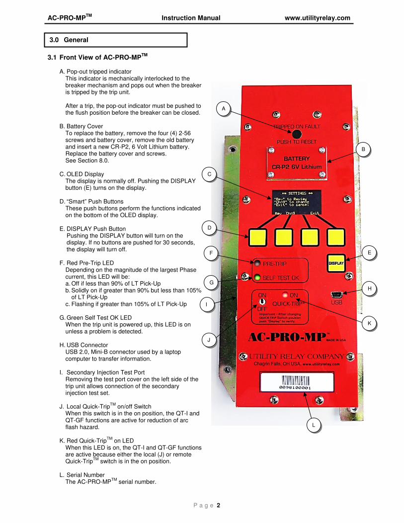
3.1 Front View of AC-PRO-MP
TM
A. Pop-out tripped indicator
This indicator is mechanically interlocked to the breaker mechanism and pops out when the breaker is tripped by the trip unit.
After a trip, the pop-out indicator must be pushed to the flush position before the breaker can be closed.
B. Battery Cover
To replace the battery, remove the four (4) 2-56 screws and battery cover, remove the old battery and insert a new CR-P2, 6 Volt Lithium battery. Replace the battery cover and screws. See Section 8.0.
C. OLED Display
The display is normally off. Pushing the DISPLAY button (E) turns on the display.
D. “Smart” Push Buttons
These push buttons perform the functions indicated on the bottom of the OLED display.
E. DISPLAY Push Button
Pushing the DISPLAY button will turn on the display. If no buttons are pushed for 30 seconds, the display will turn off.
F. Red Pre-Trip LED Depending on the magnitude of the largest Phase current, this LED will be: a. Off if less than 90% of LT Pick-Up b. Solidly on if greater than 90% but less than 105%
of LT Pick-Up c. Flashing if greater than 105% of LT Pick-Up
G. Green Self Test OK LED
When the trip unit is powered up, this LED is on unless a problem is detected.
H. USB Connector USB 2.0, Mini-B connector used by a laptop computer to transfer information.
I. Secondary Injection Test Port Removing the test port cover on the left side of the trip unit allows connection of the secondary injection test set.
J. Local Quick-Trip
TM on/off Switch
When this switch is in the on position, the QT-I and QT-GF functions are active for reduction of arc flash hazard.
K. Red Quick-Trip
TM on LED
When this LED is on, the QT-I and QT-GF functions are active because either the local (J) or remote Quick-Trip
TM switch is in the on position.
L. Serial Number
The AC-PRO-MPTM
serial number.
3.0 General
C
D
G
A
B
E F
I
H
K
L
J
Utility Relay Company
P a g e 3
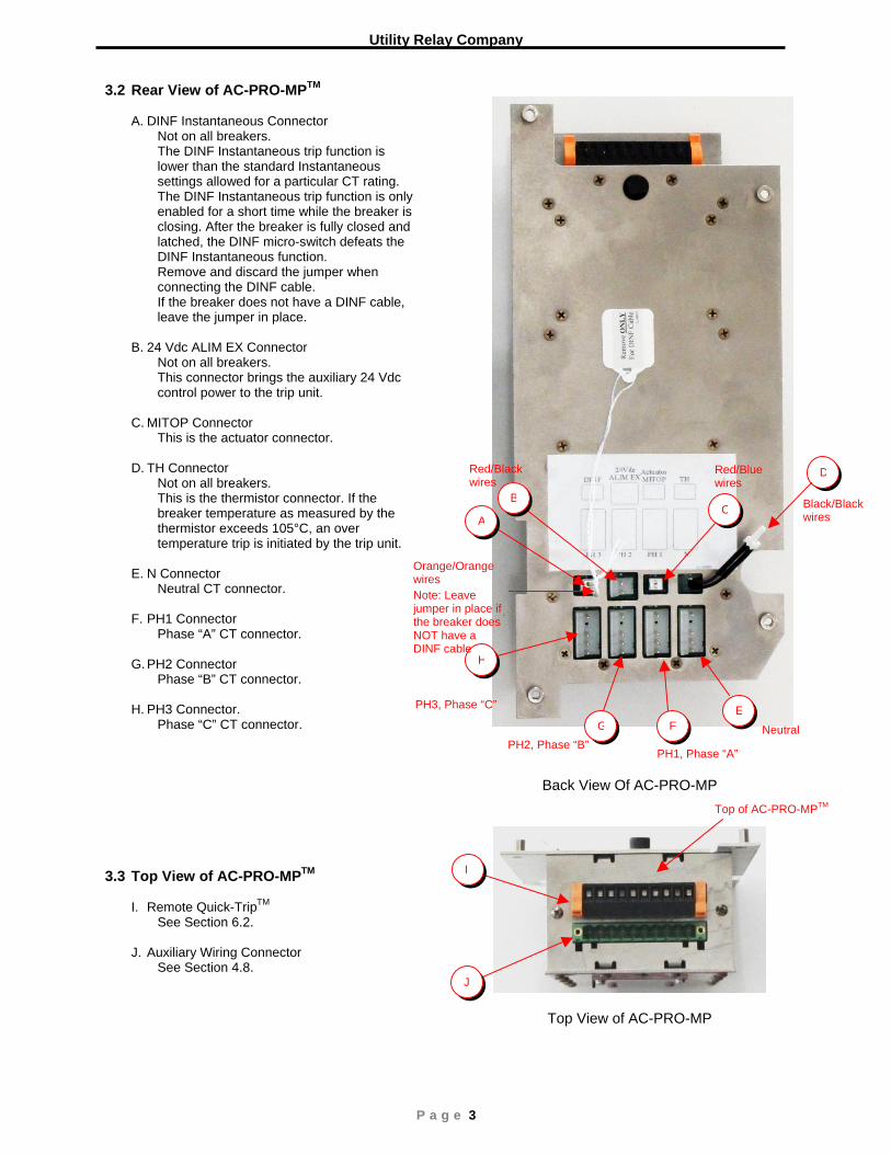
3.2 Rear View of AC-PRO-MPTM
A. DINF Instantaneous Connector Not on all breakers.
The DINF Instantaneous trip function is lower than the standard Instantaneous settings allowed for a particular CT rating. The DINF Instantaneous trip function is only enabled for a short time while the breaker is closing. After the breaker is fully closed and latched, the DINF micro-switch defeats the DINF Instantaneous function. Remove and discard the jumper when connecting the DINF cable. If the breaker does not have a DINF cable, leave the jumper in place.
B. 24 Vdc ALIM EX Connector
Not on all breakers. This connector brings the auxiliary 24 Vdc control power to the trip unit.
C. MITOP Connector
This is the actuator connector. D. TH Connector
Not on all breakers. This is the thermistor connector. If the breaker temperature as measured by the thermistor exceeds 105°C, an over temperature trip is initiated by the trip unit.
E. N Connector
Neutral CT connector.
F. PH1 Connector Phase “A” CT connector.
G. PH2 Connector
Phase “B” CT connector.
H. PH3 Connector. Phase “C” CT connector.
3.3 Top View of AC-PRO-MPTM
I. Remote Quick-TripTM
See Section 6.2. J. Auxiliary Wiring Connector
See Section 4.8.
Back View Of AC-PRO-MP
Top View of AC-PRO-MP
D
H
G FE
BC
A
I
J
Red/Black wires
Red/Blue wires
Neutral
Top of AC-PRO-MPTM
Orange/Orange wires
Black/Blackwires
PH3, Phase “C”
PH2, Phase “B”PH1, Phase “A”
Note: Leave jumper in place if the breaker does NOT have a DINF cable
AC-PRO-MPTM Instruction Manual www.utilityrelay.com
P a g e 4
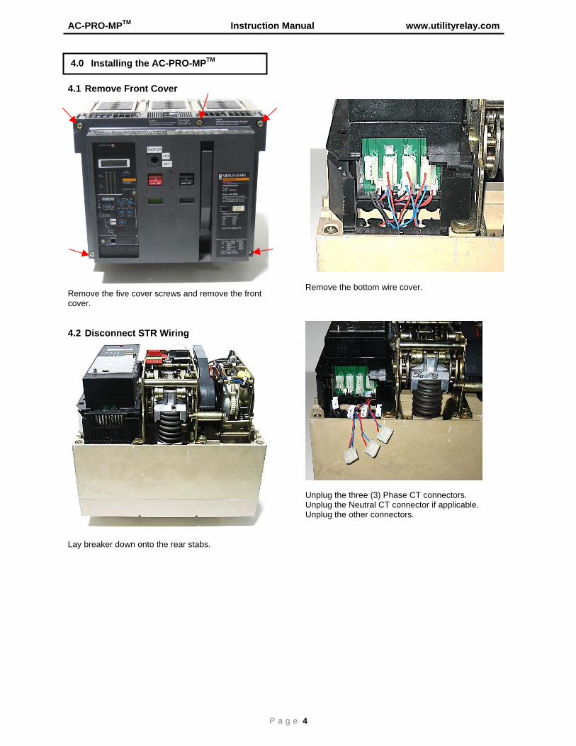
4.1 Remove Front Cover
Remove the five cover screws and remove the front cover. 4.2 Disconnect STR Wiring
Lay breaker down onto the rear stabs.
Remove the bottom wire cover.
Unplug the three (3) Phase CT connectors. Unplug the Neutral CT connector if applicable. Unplug the other connectors.
4.0 Installing the AC-PRO-MPTM
Utility Relay Company
P a g e 5
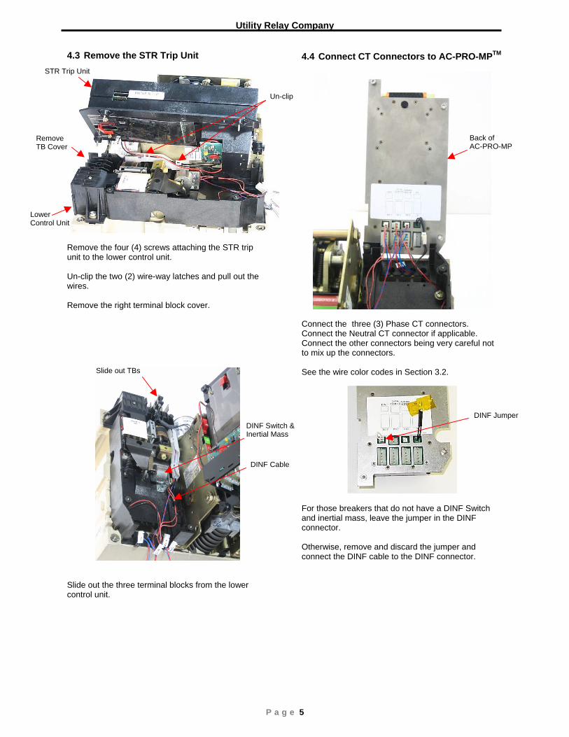
4.3 Remove the STR Trip Unit
Remove the four (4) screws attaching the STR trip unit to the lower control unit. Un-clip the two (2) wire-way latches and pull out the wires. Remove the right terminal block cover.
Slide out the three terminal blocks from the lower control unit.
4.4 Connect CT Connectors to AC-PRO-MPTM
Connect the three (3) Phase CT connectors. Connect the Neutral CT connector if applicable. Connect the other connectors being very careful not to mix up the connectors. See the wire color codes in Section 3.2.
For those breakers that do not have a DINF Switch and inertial mass, leave the jumper in the DINF connector. Otherwise, remove and discard the jumper and connect the DINF cable to the DINF connector.
DINF Switch &Inertial Mass
Un-clip
Remove TB Cover
Slide out TBs
STR Trip Unit
Lower Control Unit
DINF Jumper
DINF Cable
Back of AC-PRO-MP
AC-PRO-MPTM Instruction Manual www.utilityrelay.com
P a g e 6
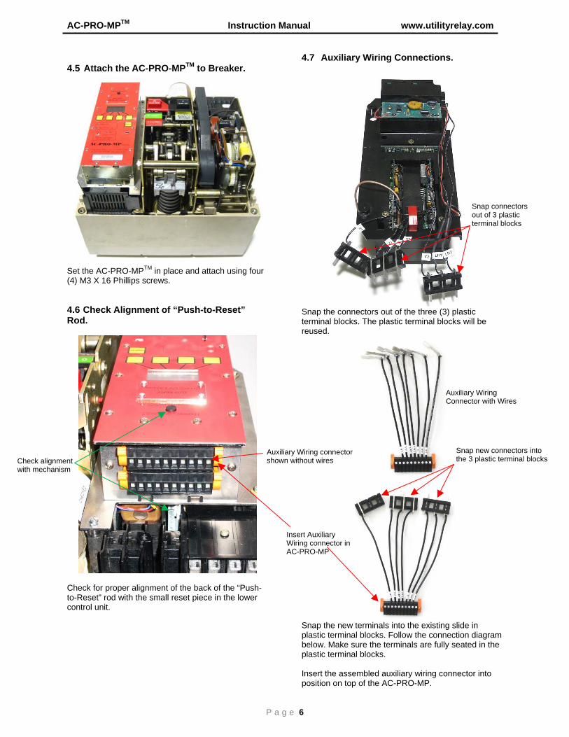
4.5 Attach the AC-PRO-MPTM to Breaker.
Set the AC-PRO-MPTM in place and attach using four (4) M3 X 16 Phillips screws.
4.6 Check Alignment of “Push-to-Reset” Rod.
Check for proper alignment of the back of the “Push-to-Reset” rod with the small reset piece in the lower control unit.
4.7 Auxiliary Wiring Connections.
Snap the connectors out of the three (3) plastic terminal blocks. The plastic terminal blocks will be reused.
Snap the new terminals into the existing slide in plastic terminal blocks. Follow the connection diagram below. Make sure the terminals are fully seated in the plastic terminal blocks. Insert the assembled auxiliary wiring connector into position on top of the AC-PRO-MP.
Check alignment with mechanism
Snap connectors out of 3 plastic terminal blocks
Snap new connectors into the 3 plastic terminal blocks
Auxiliary Wiring connector shown without wires
Insert Auxiliary Wiring connector in AC-PRO-MP
Auxiliary Wiring Connector with Wires
Utility Relay Company
P a g e 7
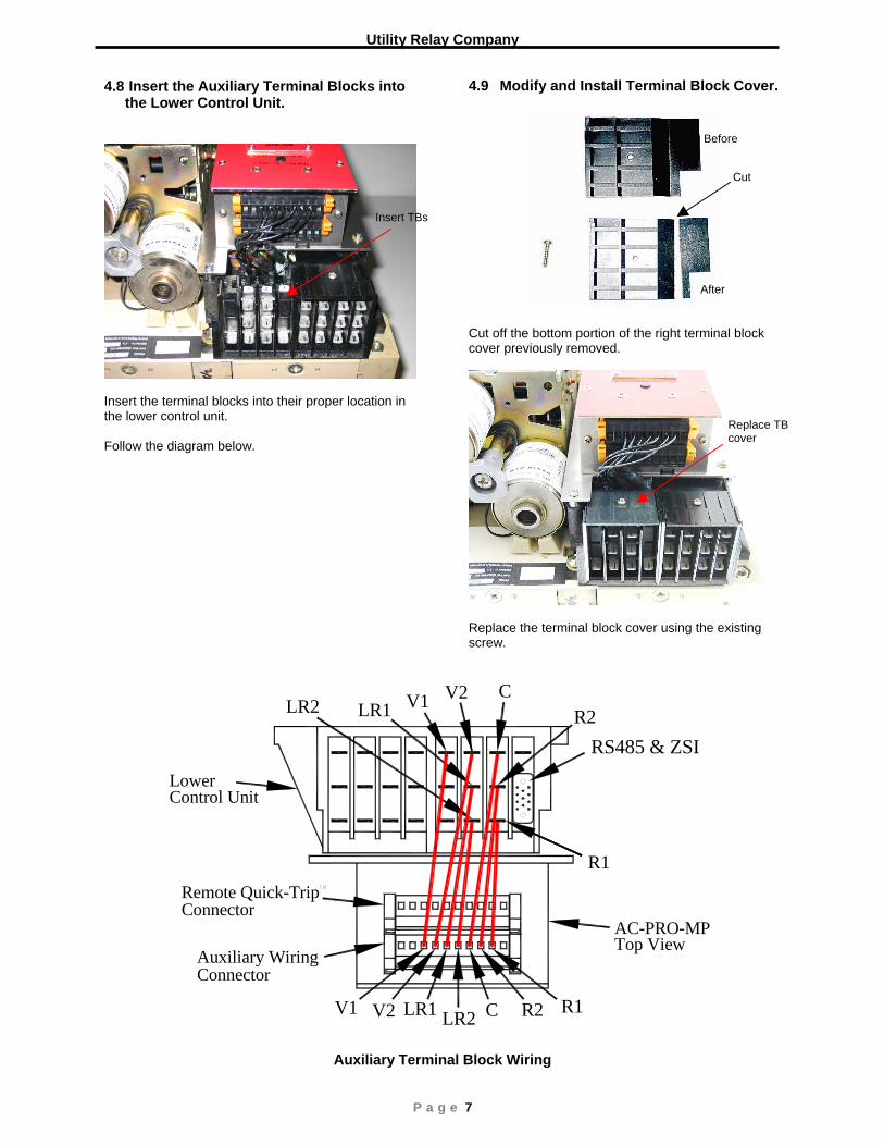
4.8 Insert the Auxiliary Terminal Blocks into the Lower Control Unit.
Insert the terminal blocks into their proper location in the lower control unit. Follow the diagram below.
4.9 Modify and Install Terminal Block Cover.
Cut off the bottom portion of the right terminal block cover previously removed.
Replace the terminal block cover using the existing screw.
V1 V2 CLR1 R2LR2
R1
6
RS485 & ZSI
V1 V2 LR1 LR2 C R2 R1
Auxiliary Wiring
Remote Quick-Trip
Connector
Connector
Control UnitLower
AC-PRO-MPTop View
Auxiliary Terminal Block Wiring
Cut
Before
After
Replace TB cover
Insert TBs
AC-PRO-MPTM Instruction Manual www.utilityrelay.com
P a g e 8
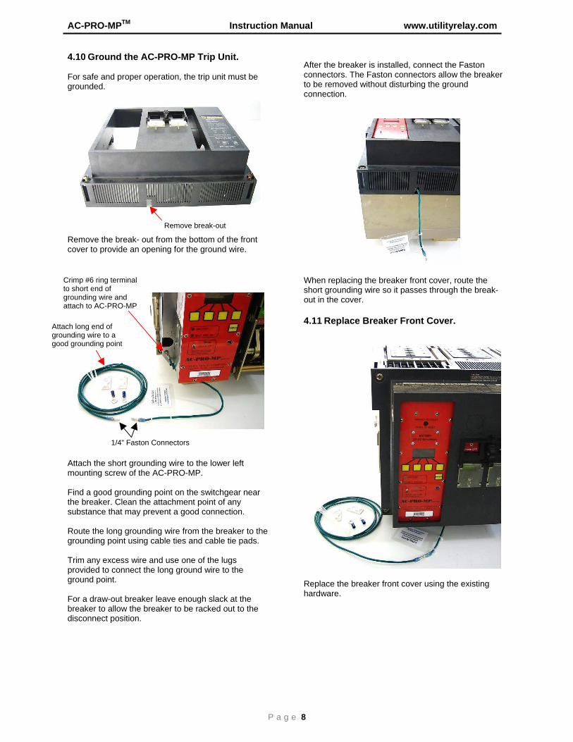
4.10 Ground the AC-PRO-MP Trip Unit. For safe and proper operation, the trip unit must be grounded.
Remove the break- out from the bottom of the front cover to provide an opening for the ground wire.
Attach the short grounding wire to the lower left mounting screw of the AC-PRO-MP. Find a good grounding point on the switchgear near the breaker. Clean the attachment point of any substance that may prevent a good connection. Route the long grounding wire from the breaker to the grounding point using cable ties and cable tie pads. Trim any excess wire and use one of the lugs provided to connect the long ground wire to the ground point. For a draw-out breaker leave enough slack at the breaker to allow the breaker to be racked out to the disconnect position.
After the breaker is installed, connect the Faston connectors. The Faston connectors allow the breaker to be removed without disturbing the ground connection.
When replacing the breaker front cover, route the short grounding wire so it passes through the break-out in the cover. 4.11 Replace Breaker Front Cover.
Replace the breaker front cover using the existing hardware.
Remove break-out
Crimp #6 ring terminal to short end of grounding wire and attach to AC-PRO-MP
1/4” Faston Connectors
Attach long end of grounding wire to a good grounding point
Utility Relay Company
P a g e 9
The AC-PRO-MPTM is shipped un-commissioned and must be commissioned before placing in service. The push buttons and display on the front panel or the USB Interface with a laptop computer can be used to make the initial settings or change existing settings. 5.1 Using the Front Panel Push the “DISPLAY” button to power up the trip unit. The following is displayed:
Push the “Set” button to display the security window:
The Security Code is the last four (4) digits of the Serial Number. See Section 3.1 for the location of the Serial Number. Push the “Up” or “Down” button to select the value of each digit. Use the “Next” button to advance to the next digit.
For the last digit, the following is displayed:
Push the “Enter” button after the last digit of the Security Code is entered. The following is displayed:
Push the “Up” or “Down” buttons until the desired STR trip unit type is flashing. The other STR types are displayed by pushing the “Up” button several times.
After pushing “Enter”, the following is displayed: (Not for 18M or 28D)
The H1/N1 breakers have standard or special interrupting rating and the H2 breakers have high interrupting rating.
5.0 Entering or Changing Settings
** “WARNING” ** Enter Settings Before Placing In Service
Push “Set”
Set
Security Code To change settings enter 4 digit code
0 _ _ _
Up Dwn Next Exit
SECURITY CODE To Change Settings Enter 4 Digit Code
X X X X
Up Dwn Enter
SELECT STR TYPE: STR 38S RatingPlug STR 58U NoRatingPlug STR 58U RatingPlug
Up Dwn Exit Enter
SElECT STR TYPE: STR 18M STR 28D NoRatingPlug STR 28D RatingPlug STR 38S NoRatingPlug Up Dwn Exit Enter
Breaker Type: H2 H1/N1 H2 Back Enter
**** IMPORTANT **** The trip unit will NOT FUNCTION as it is shipped from the factory. The user must first COMMISSION the unit as outlined in this Section to make it functional.
AC-PRO-MPTM Instruction Manual www.utilityrelay.com
P a g e 10
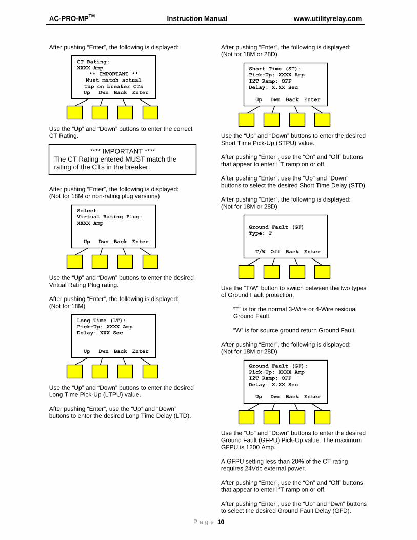
After pushing “Enter”, the following is displayed:
Use the “Up” and “Down” buttons to enter the correct CT Rating. After pushing “Enter”, the following is displayed: (Not for 18M or non-rating plug versions)
Use the “Up” and “Down” buttons to enter the desired Virtual Rating Plug rating. After pushing “Enter”, the following is displayed: (Not for 18M)
Use the “Up” and “Down” buttons to enter the desired Long Time Pick-Up (LTPU) value. After pushing “Enter”, use the “Up” and “Down” buttons to enter the desired Long Time Delay (LTD).
After pushing “Enter”, the following is displayed: (Not for 18M or 28D)
Use the “Up” and “Down” buttons to enter the desired Short Time Pick-Up (STPU) value. After pushing “Enter”, use the “On” and “Off” buttons that appear to enter I2T ramp on or off. After pushing “Enter”, use the “Up” and “Down” buttons to select the desired Short Time Delay (STD). After pushing “Enter”, the following is displayed: (Not for 18M or 28D)
Use the “T/W” button to switch between the two types of Ground Fault protection. “T” is for the normal 3-Wire or 4-Wire residual
Ground Fault. “W” is for source ground return Ground Fault. After pushing “Enter”, the following is displayed: (Not for 18M or 28D)
Use the “Up” and “Down” buttons to enter the desired Ground Fault (GFPU) Pick-Up value. The maximum GFPU is 1200 Amp. A GFPU setting less than 20% of the CT rating requires 24Vdc external power. After pushing “Enter”, use the “On” and “Off” buttons that appear to enter I2T ramp on or off. After pushing “Enter”, use the “Up” and “Dwn” buttons to select the desired Ground Fault Delay (GFD).
CT Rating: XXXX Amp
** IMPORTANT ** Must match actual Tap on breaker CTs
Up Dwn Back Enter
**** IMPORTANT **** The CT Rating entered MUST match the rating of the CTs in the breaker.
Select Virtual Rating Plug: XXXX Amp Up Dwn Back Enter
Long Time (LT): Pick-Up: XXXX Amp Delay: XXX Sec Up Dwn Back Enter
Short Time (ST): Pick-Up: XXXX Amp I2T Ramp: OFF Delay: X.XX Sec Up Dwn Back Enter
Ground Fault (GF) Type: T T/W Off Back Enter
Ground Fault (GF): Pick-Up: XXXX Amp I2T Ramp: OFF Delay: X.XX Sec Up Dwn Back Enter
Utility Relay Company
P a g e 11
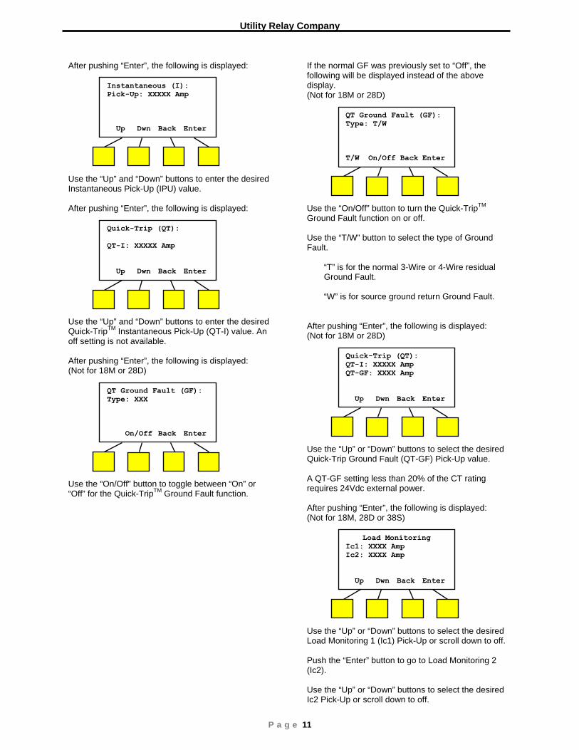
After pushing “Enter”, the following is displayed:
Use the “Up” and “Down” buttons to enter the desired Instantaneous Pick-Up (IPU) value.
After pushing “Enter”, the following is displayed:
Use the “Up” and “Down” buttons to enter the desired Quick-TripTM Instantaneous Pick-Up (QT-I) value. An off setting is not available.
After pushing “Enter”, the following is displayed: (Not for 18M or 28D)
Use the “On/Off” button to toggle between “On” or “Off” for the Quick-TripTM Ground Fault function.
If the normal GF was previously set to “Off”, the following will be displayed instead of the above display. (Not for 18M or 28D)
Use the “On/Off” button to turn the Quick-TripTM Ground Fault function on or off. Use the “T/W” button to select the type of Ground Fault. “T” is for the normal 3-Wire or 4-Wire residual
Ground Fault. “W” is for source ground return Ground Fault. After pushing “Enter”, the following is displayed: (Not for 18M or 28D)
Use the “Up” or “Down” buttons to select the desired Quick-Trip Ground Fault (QT-GF) Pick-Up value. A QT-GF setting less than 20% of the CT rating requires 24Vdc external power.
After pushing “Enter”, the following is displayed: (Not for 18M, 28D or 38S)
Use the “Up” or “Down” buttons to select the desired Load Monitoring 1 (Ic1) Pick-Up or scroll down to off. Push the “Enter” button to go to Load Monitoring 2 (Ic2). Use the “Up” or “Down” buttons to select the desired Ic2 Pick-Up or scroll down to off.
Instantaneous (I): Pick-Up: XXXXX Amp Up Dwn Back Enter
Quick-Trip (QT): QT-I: XXXXX Amp Up Dwn Back Enter
QT Ground Fault (GF): Type: XXX On/Off Back Enter
Quick-Trip (QT): QT-I: XXXXX Amp QT-GF: XXXX Amp Up Dwn Back Enter
QT Ground Fault (GF): Type: T/W T/W On/Off Back Enter
Load Monitoring Ic1: XXXX Amp Ic2: XXXX Amp Up Dwn Back Enter
AC-PRO-MPTM Instruction Manual www.utilityrelay.com
P a g e 12
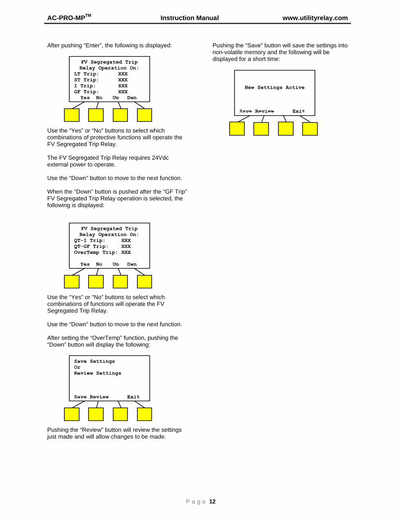
After pushing “Enter”, the following is displayed:
Use the “Yes” or “No” buttons to select which combinations of protective functions will operate the FV Segregated Trip Relay. The FV Segregated Trip Relay requires 24Vdc external power to operate. Use the “Down” button to move to the next function. When the “Down” button is pushed after the “GF Trip” FV Segregated Trip Relay operation is selected, the following is displayed:
Use the “Yes” or “No” buttons to select which combinations of functions will operate the FV Segregated Trip Relay. Use the “Down” button to move to the next function. After setting the “OverTemp” function, pushing the “Down” button will display the following:
Pushing the “Review” button will review the settings just made and will allow changes to be made.
Pushing the “Save” button will save the settings into non-volatile memory and the following will be displayed for a short time:
FV Segregated Trip Relay Operation On:
LT Trip: XXX ST Trip: XXX I Trip: XXX GF Trip: XXX Yes No Up Dwn
FV Segregated Trip Relay Operation On:
QT-I Trip: XXX QT-GF Trip: XXX OverTemp Trip: XXX Yes No Up Dwn
Save Settings Or Review Settings Save Review Exit
New Settings Active
Save Review Exit
Utility Relay Company
P a g e 13
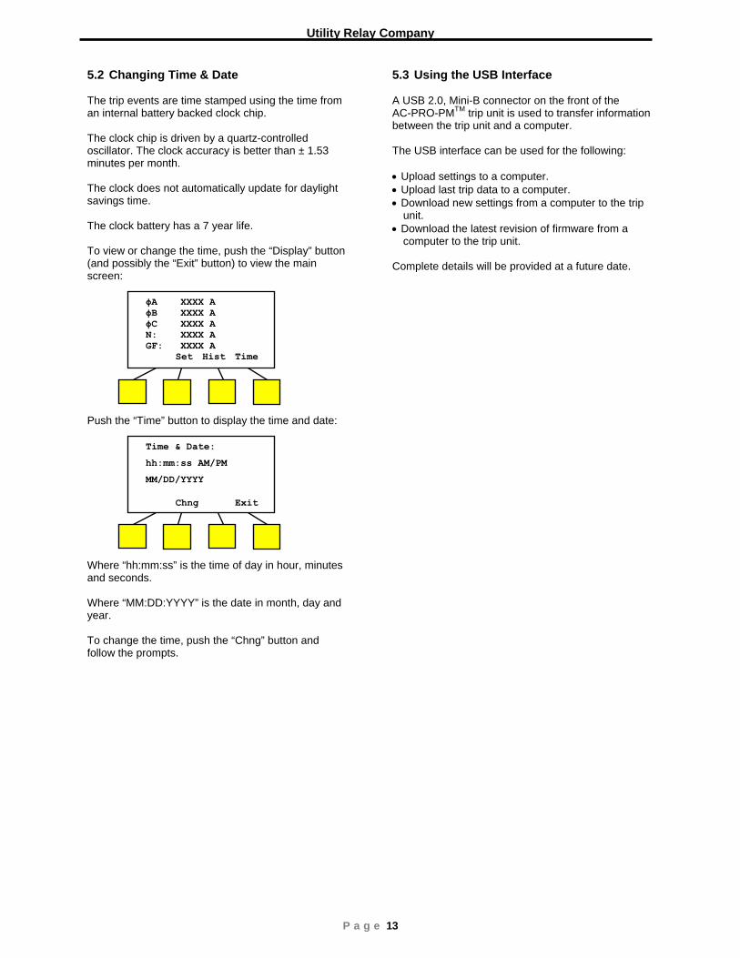
5.2 Changing Time & Date The trip events are time stamped using the time from an internal battery backed clock chip. The clock chip is driven by a quartz-controlled oscillator. The clock accuracy is better than ± 1.53 minutes per month. The clock does not automatically update for daylight savings time. The clock battery has a 7 year life. To view or change the time, push the “Display” button (and possibly the “Exit” button) to view the main screen:
Push the “Time” button to display the time and date:
Where “hh:mm:ss” is the time of day in hour, minutes and seconds. Where “MM:DD:YYYY” is the date in month, day and year. To change the time, push the “Chng” button and follow the prompts.
5.3 Using the USB Interface A USB 2.0, Mini-B connector on the front of the AC-PRO-PMTM trip unit is used to transfer information between the trip unit and a computer. The USB interface can be used for the following: • Upload settings to a computer. • Upload last trip data to a computer. • Download new settings from a computer to the trip
unit. • Download the latest revision of firmware from a
computer to the trip unit. Complete details will be provided at a future date.
ϕA XXXX A ϕB XXXX A ϕC XXXX A N: XXXX A GF: XXXX A
Set Hist Time
Time & Date:
hh:mm:ss AM/PM
MM/DD/YYYY
Chng Exit
AC-PRO-MPTM
Instruction Manual www.utilityrelay.com
P a g e 14
The Quick-Trip
TM system (patents 7,646,575 &
7,889,474) is a manually controlled Zone Selective Interlock (ZSI) system. It can reduce trip times when turned on and allows selective coordination between circuit breakers when turned off. If maintenance personnel must work on energized equipment, they will first turn the Quick-Trip
TM system
on at the breaker feeding the equipment. If a fault now occurs, the upstream breaker will trip quickly based on the Quick-Trip
TM settings reducing the Arc Flash
Hazard to personnel. When the work is done, the Quick-Trip
TM system is
turned off and the original selective coordination is back in effect. When Quick-Trip
TM is on, the following settings are
enabled:
• Quick-Trip Instantaneous (QT-I)
• Quick-Trip Ground Fault (QT-GF) All other settings remain in effect. The “QUICK-TRIP
TM ON LED” provides positive
indication that the Quick-TripTM
settings are active if the LED is on.
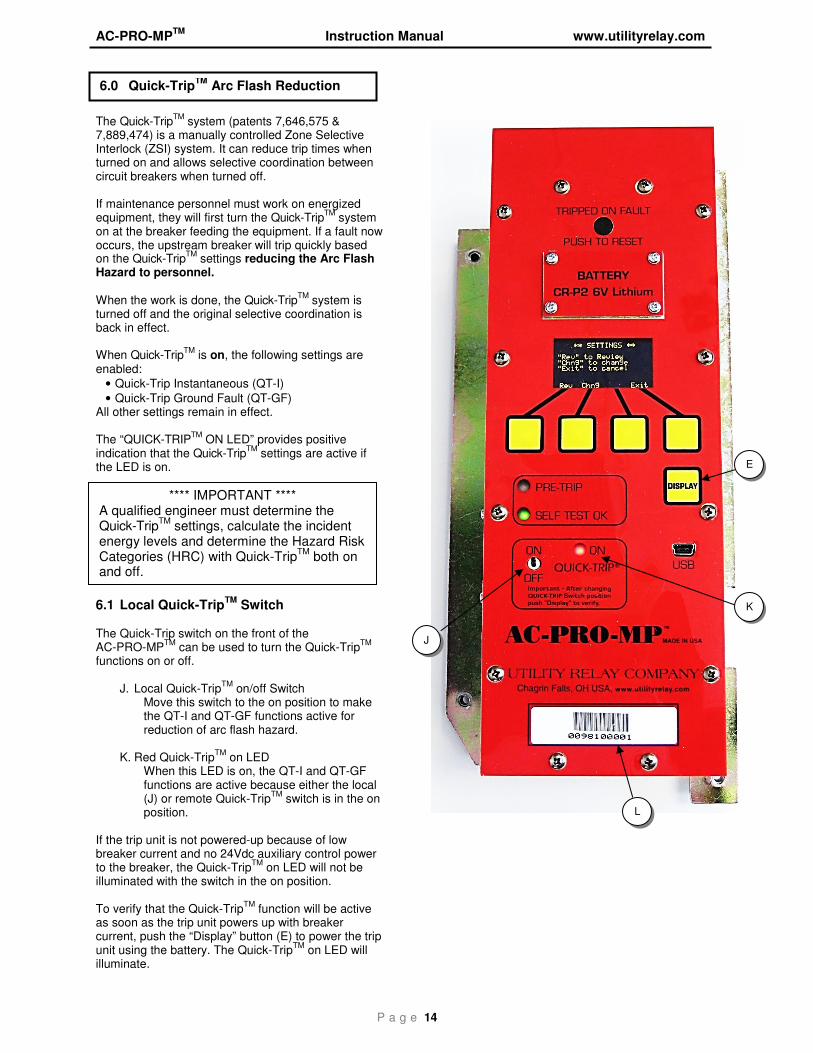
6.1 Local Quick-TripTM
Switch The Quick-Trip switch on the front of the AC-PRO-MP
TM can be used to turn the Quick-Trip
TM
functions on or off.
J. Local Quick-TripTM
on/off Switch Move this switch to the on position to make the QT-I and QT-GF functions active for reduction of arc flash hazard.
K. Red Quick-TripTM
on LED When this LED is on, the QT-I and QT-GF functions are active because either the local (J) or remote Quick-Trip
TM switch is in the on
position.
If the trip unit is not powered-up because of low breaker current and no 24Vdc auxiliary control power to the breaker, the Quick-Trip
TM on LED will not be
illuminated with the switch in the on position. To verify that the Quick-Trip
TM function will be active
as soon as the trip unit powers up with breaker current, push the “Display” button (E) to power the trip unit using the battery. The Quick-Trip
TM on LED will
illuminate.
6.0 Quick-TripTM
Arc Flash Reduction Changing Settings
**** IMPORTANT **** A qualified engineer must determine the Quick-Trip
TM settings, calculate the incident
energy levels and determine the Hazard Risk Categories (HRC) with Quick-Trip
TM both on
and off.
E
K
L
J
Utility Relay Company
P a g e 15
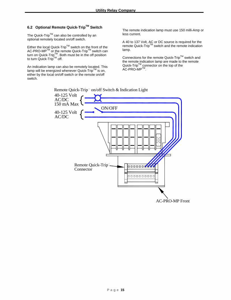
6.2 Optional Remote Quick-TripTM Switch The Quick-TripTM can also be controlled by an optional remotely located on/off switch. Either the local Quick-TripTM switch on the front of the AC-PRO-MPTM or the remote Quick-TripTM switch can turn on Quick-TripTM. Both must be in the off position to turn Quick-TripTM off. An indication lamp can also be remotely located. This lamp will be energized whenever Quick-TripTM is on, either by the local on/off switch or the remote on/off switch.
The remote indication lamp must use 150 milli-Amp or less current. A 40 to 137 Volt, AC or DC source is required for the remote Quick-TripTM switch and the remote indication lamp. Connections for the remote Quick-TripTM switch and the remote indication lamp are made to the remote Quick-TripTM connector on the top of the AC-PRO-MPTM.
Remote Quick-Trip Connector
40-125 VoltAC/DC
40-125 VoltAC/DC
150 mA Max
AC-PRO-MP Front
Remote Quick-Trip on/off Switch & Indication Light
ON/OFF
AC-PRO-MPTM
Instruction Manual www.utilityrelay.com
P a g e 16
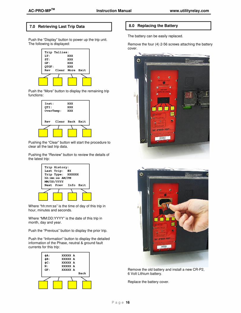
Push the “Display” button to power up the trip unit. The following is displayed:
Push the “More” button to display the remaining trip functions:
Pushing the “Clear” button will start the procedure to clear all the last trip data. Pushing the “Review” button to review the details of the latest trip:
Where “hh:mm:ss” is the time of day of this trip in hour, minutes and seconds. Where “MM:DD:YYYY” is the date of this trip in month, day and year. Push the “Previous” button to display the prior trip. Push the “Information” button to display the detailed information of the Phase, neutral & ground fault currents for this trip:
The battery can be easily replaced. Remove the four (4) 2-56 screws attaching the battery cover.
Remove the old battery and install a new CR-P2, 6 Volt Lithium battery. Replace the battery cover.
7.0 Retrieving Last Trip Data 8.0 Replacing the Battery
Trip Tallies: LT: XXX
ST: XXX GF: XXX
QTGF: XXX
Rev Clear More Exit
Inst: XXX
QTI: XXX OverTemp: XXX
Rev Clear Back Exit
Trip History: Last Trip: #X
Trip Type: XXXXXX hh:mm:ss AM/PM
MM/DD/YYYY Next Prev Info Exit
ϕA: XXXXX A ϕB: XXXXX A
ϕC: XXXXX A N: XXXXX A
GF: XXXXX A Back
Utility Relay Company
P a g e 17
The AC-PRO-MP continually performs self tests in the background. If an internal problem is detected, the “Self Test OK” LED is turned off. The internal self tests include: • Watch dog timer • Memory check sum • Memory access error • Low battery voltage • Actuator connected 10.1 Primary Injection Testing A primary injection test is recommended as the final test of the AC-PRO-MPTM. This tests the complete system. If Ground Fault with the “T” option (residual) is used, GF must be temporarily turned off when single phase testing the other trip functions with a primary injection test set.
10.2 Secondary Injection Testing
The AC-PRO-MPTM secondary injection test set provides a quick and easy way to test the AC-PRO-MPTM trip units. The test set does a true test of each Phase and can also test the Ground Fault function. The test set plugs into a port on the left side of the test AC-PRO-MPTM. Follow the instructions provided with the test set.
Some Masterpact MP breakers have a DINF Instantaneous (DINF-I) feature. The DINF-I trip function is only enabled for a short time while the breaker is closing. After the breaker is fully closed and latched, the DINF-I trip function is disabled by the DINF micro-switch. The DINF-I function is controlled with a micro-switch and inertial mass. They are located in the lower control unit as shown in Section 4.3. The connection to the AC-PRO-MP trip unit is via connector “A” as shown in in Section 3.2. Not all Masterpact MP breakers are equipped with the DINF micro-switch and, therefore, the DINF-I trip function is never active. The DINF-I Pick-Up settings are fixed depend on the CT rating as shown below.
CT Rating (Amp)
DINF‐I Pick‐Up (Amp)
250 2700 400 4300 600 6500 800 8600 1200 12,900 1600 16,700 2000 20,800 2500 26,900 3000 32,300 3200 19,200 4000 24,000 5000 30,000 6300 37,800
The DINF-I Pick-Up setting is not adjustable and is also not shown on the OLED display. If the breaker does NOT have a DINF cable, leave the DINF jumper in place. See Section 4.4.
9.0 Self-Test Feature
10.0 Primary & Secondary Injection
Secondary injection test port
Secondary injection test set
11.0 DINF Instantaneous Trip
AC-PRO-MPTM Instruction Manual www.utilityrelay.com
P a g e 18
The AC-PRO-MP has a conditional 2-year warranty. Please contact Utility Relay Company for full details.
Ambient Temperature: Trip Unit Electronics: -4°F (-20°C) to 158°F (70°C) OLED Display: -22°F (-30°C) to 158°F (70°C) Battery: -4°F (-20°C) to 140°F (60°C) Internal Clock Battery: 32°F (0°C) to 140°F (70°C) Humidity: 95% non-condensing Conformal Coating: Acrylic conformal coating, HumiSeal type 1A33 UL Component File #E105698 Enclosure: 14 Gauge, type 304 stainless steel Battery: Panasonic CR-P2 6 Volt, 1400 mAh Lithium Non-Rechargeable
12.0 Warranty
13.0 Environmental Ratings
Utility Relay Company
P a g e 19
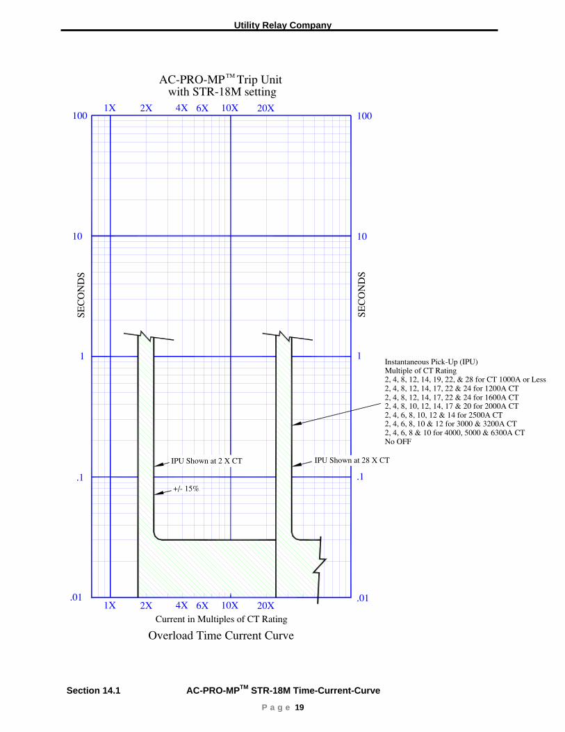
Multiple of CT RatingInstantaneous Pick−Up (IPU)
2, 4, 8, 12, 14, 19, 22, & 28 for CT 1000A or Less
Current in Multiples of CT Rating20X2X
.011X 6X4X 10X
.01
.1
SEC
ON
DS
1
10
.1
SEC
ON
DS
1
10
Overload Time Current Curve
AC−PRO−MP Trip Unit
20X2X1X 6X4X 10X
TM
with STR−18M setting
IPU Shown at 28 X CTIPU Shown at 2 X CT
2, 4, 8, 12, 14, 17, 22 & 24 for 1200A CT
2, 4, 8, 10, 12, 14, 17 & 20 for 2000A CT2, 4, 6, 8, 10, 12 & 14 for 2500A CT2, 4, 6, 8, 10 & 12 for 3000 & 3200A CT2, 4, 6, 8 & 10 for 4000, 5000 & 6300A CTNo OFF
2, 4, 8, 12, 14, 17, 22 & 24 for 1600A CT
+/− 15%
100 100
Section 14.1 AC-PRO-MPTM STR-18M Time-Current-Curve

AC-PRO-MPTM Instruction Manual www.utilityrelay.com
P a g e 20
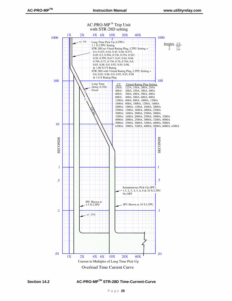
1.5, 2, 3, 4, 5, 6, 8 & 10 X LTPUInstantaneous Pick−Up (IPU)
No OFF
Current in Multiples of Long Time Pick−Up20X2X
.01
1.5 X LTPU
1X 6X4X 10X.01
.1
.5
SEC
ON
DS
1
10
.1
.5
SEC
ON
DS
1
Overload Time Current Curve
AC−PRO−MP Trip Unit
20X
100
2X1000
1X 6X4X 10X
100
1000
TR
with STR−28D setting
IPU Shown at 10 X LTPU
Delay (LTD)Fixed
IPU Shown at
Long Time Pick−Up (LTPU)1.1 X LTPU SettingSTR 28D no Vitual Rating Plug, LTPU Setting = 0.4, 0.425, 0.44, 0.45, 0.46, 0.475, 0.49, 0.5, 0.504, 0.536, 0.554, 0.567, 0.58, 0.599, 0.617, 0.63, 0.64, 0.68, 0.704, 0.72, 0.736, 0.76, 0.784, 0.8, 0.85, 0.88, 0.9, 0.92, 0.95, 0.98, & 1.00 X CT RatingSTR 28D with Virtual Rating Plug, LTPU Setting = 0.8, 0.85, 0.88, 0.9, 0.92, 0.95, 0.98 & 1.0 X Rating Plug
+/− 5%
250A: 125A, 150A, 200A, 250A400A: 200A, 250A, 300A, 400A600A: 300A, 400A, 500A, 600A800A: 400A, 500A, 600A, 800A1200A: 600A, 800A, 1000A, 1200A1600A: 800A, 1000A, 1200A, 1600A2000A: 1000A, 1200A, 1600A, 2000A2500A: 1200A, 1600A, 2000A, 2500A3000A: 1600A, 2000A, 2500A, 3000A3200A: 1600A, 2000A, 2500A, 3000A, 3200A4000A: 2000A, 2500A, 3000A, 3200A, 4000A5000A: 2500A, 3000A, 3200A, 4000A, 5000A6300A: 3000A, 3200A, 4000A, 5000A, 6000A, 6300A
CT Virtual Rating Plug SettingLong Time
+/− 15%
40X
40X
Boundary I TEF
311219
2
120 Sec
E
F
Section 14.2 AC-PRO-MPTM STR-28D Time-Current-Curve

Utility Relay Company
P a g e 21
1.5 X LTPU
1.5, 2, 3, 4, 5, 6, 8 & 10 X LTPUShort Time Pick−Up (STPU)
No OFF
Current in Multiples of Long Time Pick−Up for Short Time20X2X
.01
STPU
1X 6X4X 10X.01
.1
.5
SEC
ON
DS
1
10
.1
.5
1
Overload Time Current Curve
AC−PRO−MP Trip Unit
20X
100
2X1000
1X 6X4X 10X
100
1000
TR
with STR−38S setting
10 X LTPUSTPU
0.40 Sec
0.30 Sec
0.20 Sec
0.10 Sec
0.00 Sec STD0.00 Sec STD
Fixed at 120 SecLong Time Delay (LTD)
with & without I TShort Time Delay (STD)
2
0.40 Sec
0.30 Sec
0.20 Sec
0.10 Sec
I T OFF
I T OFF
I T OFF
2
2
2
Fixed Based on CT RatingInstantaneous Pick−Up (IPU)
24 X CT for 1200 & 1600A CT
14 X CT for 2500A CT20 X CT for 2000A CT
12 X CT for 3000 & 3200A CT10 X CT for 4000, 5000 & 6300A CTNo OFF for "H2" type Breaker
IPU Shown at 28 X CT
Current in Multiples of CT Rating for Instantaneous
28 X CT for 250A to 800A CT
0.30 Sec I T ON
2
0.20 Sec I T ON
20.10 Sec I T ON
2
at 1.5 X LTPU
Long Time Pick−Up (LTPU)1.1 X LTPU SettingSTR 38S no Vitual Rating Plug, LTPU Setting = 0.4, 0.425, 0.44, 0.45, 0.46, 0.475, 0.49, 0.5, 0.504, 0.536, 0.554, 0.567, 0.58, 0.599, 0.617, 0.63, 0.64, 0.68, 0.704, 0.72, 0.736, 0.76, 0.784, 0.8, 0.85, 0.88, 0.9, 0.92, 0.95, 0.98, & 1.00 X CT RatingSTR 38S with Virtual Rating Plug, LTPU Setting = 0.8, 0.85, 0.88, 0.9, 0.92, 0.95, 0.98 & 1.0 X Virtual Rating Plug
+/− 5%
250A: 125A, 150A, 200A, 250A400A: 200A, 250A, 300A, 400A600A: 300A, 400A, 500A, 600A800A: 400A, 500A, 600A, 800A1200A: 600A, 800A, 1000A, 1200A1600A: 800A, 1000A, 1200A, 1600A2000A: 1000A, 1200A, 1600A, 2000A2500A: 1200A, 1600A, 2000A, 2500A3000A: 1600A, 2000A, 2500A, 3000A3200A: 1600A, 2000A, 2500A, 3000A, 3200A4000A: 2000A, 2500A, 3000A, 3200A, 4000A5000A: 2500A, 3000A, 3200A, 4000A, 5000A6300A: 3000A, 3200A, 4000A, 5000A, 6000A, 6300A
CT Virtual Rating Plug Setting
+/− 15%
+/− 15%
Boundary I TEFWXYZ
31121922.415.368.965.12
2
W
X
Y
Z
40X
40X
E
F
120 Sec
With OFF for "H1/N1" type Breaker
Section 14.3 AC-PRO-MPTM STR-38S Time-Current-Curve

AC-PRO-MPTM Instruction Manual www.utilityrelay.com
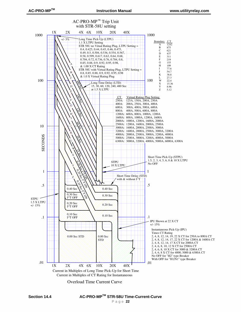
P a g e 22
1.5 X LTPU
1.5, 2, 3, 4, 5, 6, 8 & 10 X LTPUShort Time Pick−Up (STPU)
No OFF
Current in Multiples of Long Time Pick−Up for Short Time20X2X
.01
STPU
1X 6X4X 10X.01
.1
.5
SEC
ON
DS
1
10
.1
.5
1
Overload Time Current Curve
AC−PRO−MP Trip Unit
20X
100
2X1000
1X 6X4X 10X
100
1000
TR
with STR−58U setting
10 X LTPUSTPU
0.40 Sec
0.30 Sec
0.20 Sec
0.10 Sec
0.00 Sec0.00 Sec STD
15, 30, 60, 120, 240, 480 SecLong Time Delay (LTD)
with & without I TShort Time Delay (STD)
2
0.40 Sec
0.30 Sec
0.20 Sec
0.10 Sec
I T OFF
I T OFF
I T OFF
2
2
2
Times CT RatingInstantaneous Pick−Up (IPU)
2, 4, 8, 12, 14, 17, 22 X CT for 1200A & 1600A CT
2, 4, 6, 8, 10, 12 X CT for 2500A CT2, 4, 8, 12, 14, 17 X CT for 2000A CT
2, 4, 6, 8, 10 X CT for 3000 & 3200A CT2, 4, 6, 8 X CT for 4000, 5000 & 6300A CTNo OFF for "H2" type Breaker
IPU Shown at 22 X CT
Current in Multiples of CT Rating for Instantaneous
2, 4, 8, 12, 14, 19, 22 X CT for 250A to 800A CT
0.30 Sec I T ON
2
0.20 Sec I T ON
20.10 Sec I T ON
2
at 1.5 X LTPU
15 Sec30 Sec
60 Sec120 Sec
240 Sec480 Sec
Long Time Pick−Up (LTPU)1.1 X LTPU SettingSTR 58U no Vitual Rating Plug, LTPU Setting = 0.4, 0.425, 0.44, 0.45, 0.46, 0.475, 0.49, 0.5, 0.504, 0.536, 0.554, 0.567, 0.58, 0.599, 0.617, 0.63, 0.64, 0.68, 0.704, 0.72, 0.736, 0.76, 0.784, 0.8, 0.85, 0.88, 0.9, 0.92, 0.95, 0.98, & 1.00 X CT RatingSTR 58U with Virtual Rating Plug, LTPU Setting = 0.8, 0.85, 0.88, 0.9, 0.92, 0.95, 0.98 & 1.0 X Virtual Rating Plug
+/− 5%
250A: 125A, 150A, 200A, 250A400A: 200A, 250A, 300A, 400A600A: 300A, 400A, 500A, 600A800A: 400A, 500A, 600A, 800A1200A: 600A, 800A, 1000A, 1200A1600A: 800A, 1000A, 1200A, 1600A2000A: 1000A, 1200A, 1600A, 2000A2500A: 1200A, 1600A, 2000A, 2500A3000A: 1600A, 2000A, 2500A, 3000A3200A: 1600A, 2000A, 2500A, 3000A, 3200A4000A: 2000A, 2500A, 3000A, 3200A, 4000A5000A: 2500A, 3000A, 3200A, 4000A, 5000A6300A: 3000A, 3200A, 4000A, 5000A, 6000A, 6300A
CT Virtual Rating Plug Setting
+/− 15%
+/− 15%
Boundary I TABCDEFGHIJKLWXYZ
124287562143731121915510977.654.738.827.322.415.368.965.12
2
A
B
C
D
E
F
G
H
I
J
K
L
W
X
Y
Z
40X
40X
STD
With OFF for "H1/N1" type Breaker
Section 14.4 AC-PRO-MPTM STR-58U Time-Current-Curve

Utility Relay Company
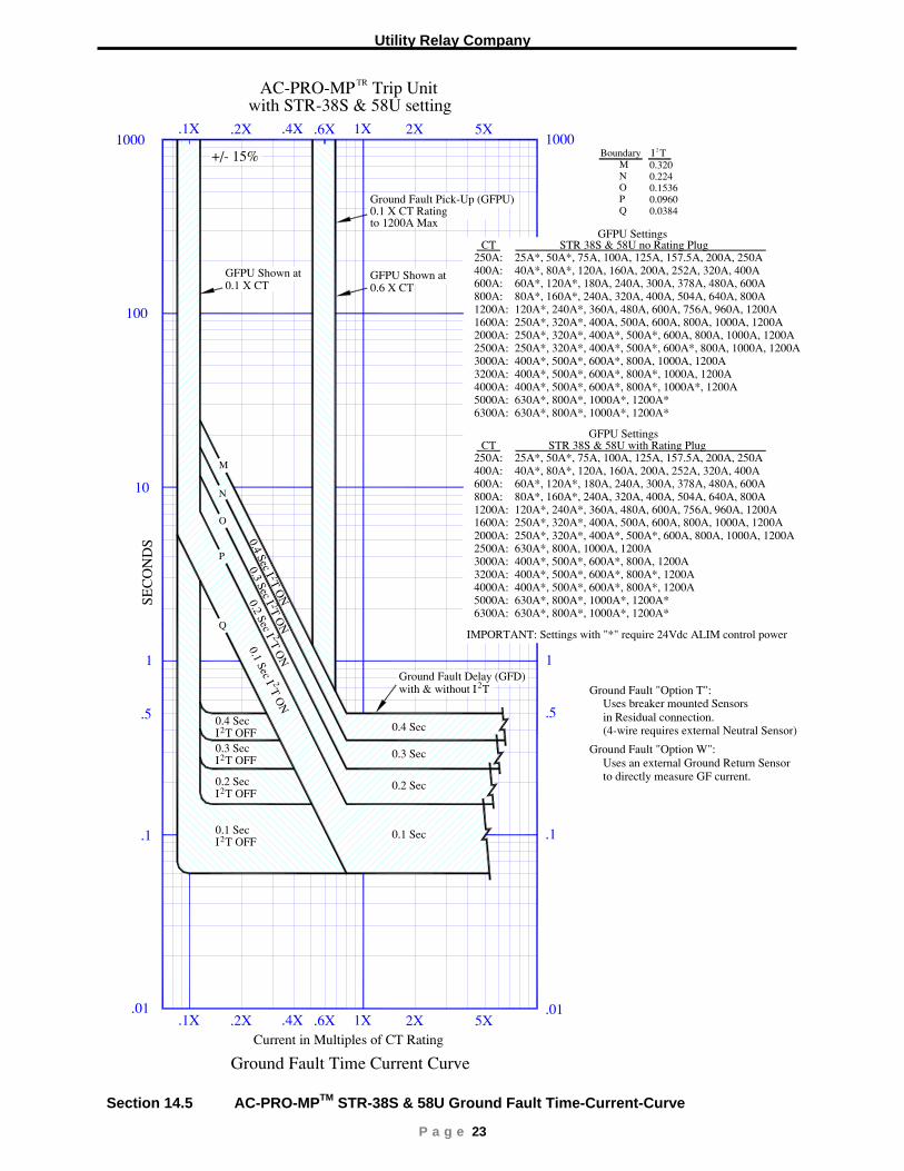
P a g e 23
.1
Current in Multiples of CT Rating
.01 .01
.1
.5
SEC
ON
DS
1
10
.5
1
Ground Fault Time Current Curve
AC−PRO−MP Trip Unit
2X
100
.2X1000
.1X .6X.4X 1X1000
TR
with STR−38S & 58U setting5X
2X.2X.1X .6X.4X 1X 5X
0.1 X CT
0.1 X CT Rating
GFPU Shown at0.6 X CTGFPU Shown at
Ground Fault Pick−Up (GFPU)
to 1200A Max
0.4 Sec
with & without I TGround Fault Delay (GFD)
0.4 Sec I T ON
2
0.3 SecI T OFF2
0.4 SecI T OFF2
0.2 SecI T OFF2
0.1 SecI T OFF2
0.3 Sec
0.2 Sec
0.1 Sec
2
0.3 Sec I T ON
20.2 Sec I T ON
2
0.1 Sec I T ON
2
Boundary I TMNOPQ
0.3200.2240.15360.09600.0384
2
250A:400A:600A:800A:1200A:1600A:2000A:2500A:3000A:3200A:4000A:5000A:6300A:
CT25A*, 50A*, 75A, 100A, 125A, 157.5A, 200A, 250A40A*, 80A*, 120A, 160A, 200A, 252A, 320A, 400A60A*, 120A*, 180A, 240A, 300A, 378A, 480A, 600A80A*, 160A*, 240A, 320A, 400A, 504A, 640A, 800A120A*, 240A*, 360A, 480A, 600A, 756A, 960A, 1200A250A*, 320A*, 400A, 500A, 600A, 800A, 1000A, 1200A250A*, 320A*, 400A*, 500A*, 600A, 800A, 1000A, 1200A250A*, 320A*, 400A*, 500A*, 600A*, 800A, 1000A, 1200A400A*, 500A*, 600A*, 800A, 1000A, 1200A400A*, 500A*, 600A*, 800A*, 1000A, 1200A400A*, 500A*, 600A*, 800A*, 1000A*, 1200A
STR 38S & 58U no Rating Plug
630A*, 800A*, 1000A*, 1200A*630A*, 800A*, 1000A*, 1200A*
250A:400A:600A:800A:1200A:1600A:2000A:2500A:3000A:3200A:4000A:5000A:6300A:
CT25A*, 50A*, 75A, 100A, 125A, 157.5A, 200A, 250A40A*, 80A*, 120A, 160A, 200A, 252A, 320A, 400A60A*, 120A*, 180A, 240A, 300A, 378A, 480A, 600A80A*, 160A*, 240A, 320A, 400A, 504A, 640A, 800A120A*, 240A*, 360A, 480A, 600A, 756A, 960A, 1200A250A*, 320A*, 400A, 500A, 600A, 800A, 1000A, 1200A250A*, 320A*, 400A*, 500A*, 600A, 800A, 1000A, 1200A630A*, 800A, 1000A, 1200A400A*, 500A*, 600A*, 800A, 1200A400A*, 500A*, 600A*, 800A*, 1200A400A*, 500A*, 600A*, 800A*, 1200A
STR 38S & 58U with Rating Plug
630A*, 800A*, 1000A*, 1200A*630A*, 800A*, 1000A*, 1200A*
IMPORTANT: Settings with "*" require 24Vdc ALIM control power
M
N
O
P
Q
Ground Fault "Option T":Uses breaker mounted Sensors
Ground Fault "Option W":
(4−wire requires external Neutral Sensor)
Uses an external Ground Return Sensor
GFPU Settings
GFPU Settings
in Residual connection.
to directly measure GF current.
+/− 15%
Section 14.5 AC-PRO-MPTM STR-38S & 58U Ground Fault Time-Current-Curve

AC-PRO-MPTM Instruction Manual www.utilityrelay.com
P a g e 24
Current in Multiples of Long Time Pick−Up (LTPU)
.01 .01
.1
SEC
ON
DS
1
10
.1
SEC
ON
DS
1
10
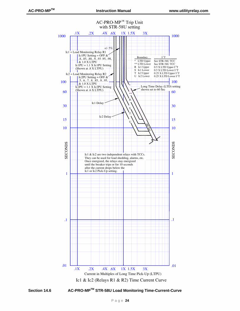
Ic1 & Ic2 (Relays R1 & R2) Time Current Curve
AC−PRO−MP Trip Unit
3X
100
.2X1000
.1X .6X.4X 1X
100
1000
TR
with STR−58U setting1.5X
3X.2X.1X .6X.4X 1X 1.5X
15 15
30 30
60 60
Ic1PU Setting = OFF &.8, .85, .88, .9, .93 .95, .98,& 1.0 X LTPU
Ic1PU = 1.1 X Ic1PU Setting
Ic2PU Setting = OFF &.5, .6, .7, .8, .85, .9, .95,& 1.0 X LTPU
Ic2PU = 1.1 X Ic2PU Setting Long Time Delay (LTD) setting
Ic1 Delay
Ic2 Delay
Ic1 = Load Monitoring Relay R1
Ic2 = Load Monitoring Relay R2
60 Sec
*
**
Ic1 & Ic2 are two independent relays with TCCs.
until the breaker trips or for 10 secondsOnce energized, the relays stay energized
after the current drops below theIc1 or Ic2 Pick−Up setting.
They can be used for load shedding, alarms, etc.
shown set to 60 Sec
Boundary* LTD Upper** LTD LowerR Ic1 UpperS Ic1 LowerT Ic2 UpperU Ic2 Lower
See STR−58U TCCSee STR−58U TCC0.5 X LTD Upper I T0.5 X LTD Lower I T0.25 X LTD Upper I T0.25 X LTD Lower I T
I T2
2
2
2
2
+/− 5%
R
S
T
U
(Shown at .8 X LTPU)
(Shown at .6 X LTPU)
Section 14.6 AC-PRO-MPTM STR-58U Load Monitoring Time-Current-Curve

Utility Relay Company
P a g e 25
Current in Multiples of CT Rating20X2X
.011X 6X4X 10X
.01
.1
SEC
ON
DS
1
10
.1
SEC
ON
DS
1
10
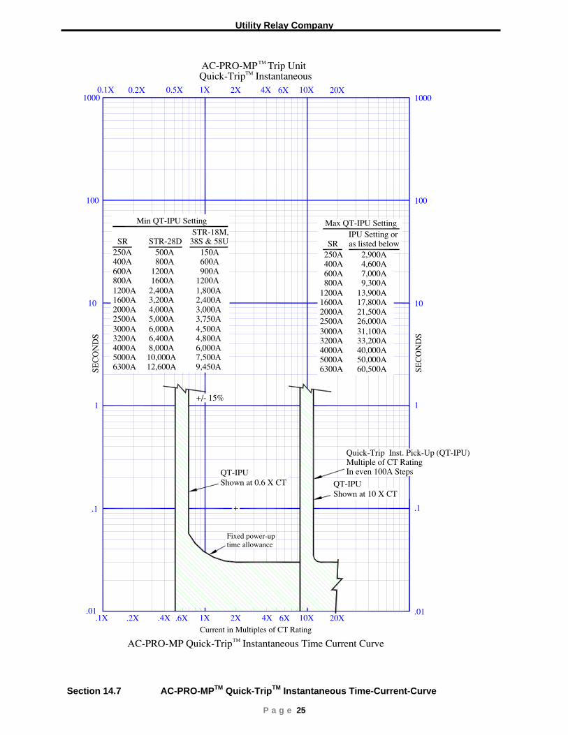
AC−PRO−MP Quick−Trip Instantaneous Time Current Curve
AC−PRO−MP Trip Unit
20X2X1X 6X4X 10X
TM
Quick−Trip Instantaneous
Shown at 10 X CTShown at 0.6 X CT
TM
TM
QT−IPUQT−IPU
0.2X0.1X 0.5X
100 100
.2X.1X .6X.4X
+/− 15%
Multiple of CT RatingQuick−Trip Inst. Pick−Up (QT−IPU)
In even 100A Steps
as listed below 2,900A 4,600A 7,000A 9,300A13,900A17,800A21,500A26,000A31,100A33,200A40,000A50,000A60,500A
IPU Setting orMax QT−IPU Setting
250A 400A 600A 800A1200A1600A2000A2500A3000A3200A4000A5000A6300A
SRSTR−28D250A 500A400A 800A600A 1200A800A 1600A1200A 2,400A1600A 3,200A2000A 4,000A2500A 5,000A3000A 6,000A3200A 6,400A4000A 8,000A5000A 10,000A6300A 12,600A
Min QT−IPU Setting
150A 600A 900A1200A1,800A2,400A3,000A3,750A4,500A4,800A6,000A7,500A9,450A
38S & 58U SRSTR−18M,
1000 1000
Fixed power−uptime allowance
Section 14.7 AC-PRO-MPTM Quick-TripTM Instantaneous Time-Current-Curve

AC-PRO-MPTM Instruction Manual www.utilityrelay.com
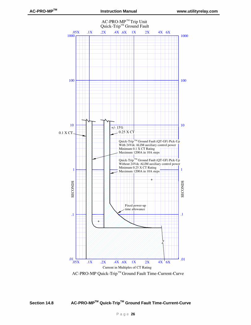
P a g e 26
Current in Multiples of CT Rating
2X1X 6X4X.01
.1
SEC
ON
DS
1
10
AC−PRO−MP Quick−Trip Ground Fault Time−Current−CurveTM
.2X .6X.4X.01
.1X
.1
SE
CO
ND
S
1
10
.05X
0.1 X CT 0.25 X CT
Quick−Trip Ground Fault (QT−GF) Pick−UpWithout 24Vdc ALIM auxiliary control powerMinimum 0.25 X CT RatingMaximum 1200A in 10A steps
Quick−Trip Ground Fault (QT−GF) Pick−UpWith 24Vdc ALIM auxiliary control powerMinimum 0.1 X CT RatingMaximum 1200A in 10A steps
TM
TM
100 100
AC−PRO−MP Trip UnitTM
Quick−Trip Ground FaultTM
+/− 15%
2X1X 6X4X.2X .6X.4X.1X.05X1000 1000
Fixed power−uptime allowance
Section 14.8 AC-PRO-MPTM Quick-TripTM Ground Fault Time-Current-Curve


![Power Swing Phenomena and Comparative Study of Its ... · PDF fileA. Mho relay Mho relay is the classical distance relay[5]. This relay gives a trip signal when power swing enters](https://img.pdfslide.net/doc/110x75/5a9630207f8b9a9c5b8ce22b/power-swing-phenomena-and-comparative-study-of-its-mho-relay-mho-relay-is.jpg)