Embed Size (px)
Citation preview
IIIIIIIIIIIIIIIIIII
SUP:l:'LEMENT 'ID
BIBLIOGRAPHY ON BOLTED AND RIVETED
STRUCTURAL JOINTS
by
John W. Fisher
Robert Kormanik
Ronald N. Allan
This work was carried out as a part ofthe Bibliography on Bolted and Riveted ConnectionsProject, sponsored by the Research Council onRiveted and Bolted Structural Joints.
Fritz Engineering LaboratoryDepartment of Civil Engineering
Lehigh UniversityBethlehem, Pennsylvania
February 1966
Fritz Engineering Laboratory Report No. 302.2
IIIIIIIIIIIIIIIIIII
1.
2.
3.
. 4.
.5.
6.
7.
8.
9.
CONTENTS
ABSTRACT
ACKNOWLEDGEMENTS
INTRODUCTION
ABSTRACTS (Arranged Chronologically)
TABLES (Graphical Summaries of the Experimental Work)
AUTHOR INDEX
SUBJECT INDEX
CROSS REFERENCE LIST (Correlates Material inReport 302.1 with List of References)
LIST OF REFERENCES
ii
IIIIIIIIIII-IIIIIIII
1. ABSTRACT
In this supplement are presented abstracts of most
of the work that has been performed during the past decade in
non-English speaking countries on riveted and bolted structural
joints. In addition, articles overlooked during the prepara
tion of the initial effort (302.1) and articles written up
through the end of calendar year 1965 are included.
Altogether, 249 abstracts were prepared and are
included in this report. This supplements the 241 abstracts
reported in the initial effort. A revised series of graphical
summaries are also presented for many of the abstracts reported
herein and has been combined with the summary provided in
Report 302.1. These summaries are provided for all articles
which report the results of experimental investigations. They
provide a rapid summary of the type of connection and the
major variables studied.
New lists are also provided for the user. They in
clude the subject and author indexes and a complete listing
of all the references. These lists include the material
presented in the initial report (302.1). All abstracts have
been renumbered by year.
-1-
IIIIIIIIIIIIIIIIIII
2. A C K NOW LED GEM E N T S
The investigation reported herein was conducted at Fritz
Engineering Laboratory, Lehigh University, Bethlehem" Pennsylvania.
Professor W. J. Eney is Head of the Civil Engineering Department and
of the Laboratory. The Research Council on Riveted and Bolted Struc
tural Joints has continued to sponsor the project.
Throughout the work has been guided by the Council's Com-
mittee on Bibliography (Mr. R. B. Belford, Chairman and Messrs. J. E. Burke,
E. L. Erickson, T. R. Higgins, E. J. Ruble, members). Dr. L. S. Beedle
has served as Project Director. The authors acknowledge the advice
and guidance of the Committee and Project Director.
Sincere appreciation is due Messrs. J. F. Parola and E. Chesson,
Jr. for suggesting many references to include in this report. In
addition, Dr. Chesson has provided many articles that were not otherwise
available so that suitable abstracts could be prepared.
Thanks are also due Mr. R. Sopko and his staff for preparing
the drawings; to Mrs. Carol Kostenbader for typing the manuscript; and
to Mr. William Digel for reviewing the manuscript.
Sincere appreciation is due Mr. K. P. Gaedke who assisted
in the preparation of many of the German language articles.
-2-
IIIIIIIIIIIIIIIIIII
3. I N T ROD U C T ION
As was noted in the initial volume of this bibliographic
work, the emphasis was on Council-sponsored work. The results of this
study was presented as Fritz Engineering Laboratory Report No. 302.1
entitled "Bibliography on Bolted and Riveted Structural Joints". The
coverage in that report extended in time from 1944 up to June 1964.
Most of the articles were reported in the English language and were
also readily available.
In this report all known literature not covered in the earlier
study up to December 1965 is covered. Much of the work appeared in
foreign language literature. Included are articles appearing in
West German, East German, Dutch, Austrian, Japanese, French, Belgium,
Swiss, and Italian periodicals. In addition several early works not
reported by deJonge in his bibliography on Riveted Joints which was
published in 1945 were abstracted and are reported herein.
Articles published since January 1964 in the Journals of
ASCE have had suitable abstracts prepared and they are not repeated
herein. However, these articles are listed in the List of References
which appears as in Section 9.
The abstracts in Section 4 follow the format established for
the initial report. Each abstract is printed in the middle of a special
card-type format so that it can be cut out and pasted on a 3 x 5 in.
file card if desired. Complete bibliographic information is included
with each abstract so that the article may be retrieved if desired.
-3-
IIIIIIIIIIIIIIIIIII
1All sources for each published article are listed with the principle
source listed first. The other sources are enclosed in brackets after
the principle source. Articles published by the ASCE in the Transactions
up to 1963 are listed as principle sources even though they first appeared
in the Proceedings. Articles published by AREA have the AREA Proceedings
indicated as the principle source. Original reports issued by the re-
search agency are also included in the bracketed sources.
The abstract number assigned in this supplement appears in
the bottom right hand corner. These numbers are used for reference
in all sections of this report. The numbering system used herein differs
from that used in the initial report (302.1). Numbers have been assigned
chronologically within each year.
The tables in Section 5 are designed to give a quick summary
of the experimental work. The tables in this supplement include the
material presented in the first report as well as the new material
reported herein. The revised Reference number system has been used
for all reports. Cross reference to the numbering system used in
Report 302.1 is provided in Section 8.
The list of references given in Section 9 includes all the
abstracts reported in this supplement and the initial report. An
effort has been made to make this listing as complete as possible.
All possible reference sources are included in this listing. Reference
is made to the principle source as only one abstract has been prepared.
Since reference numbers are assigned to sources which appear earlier
than the principle source, they have been assigned numbers for the year
-4-
IIIIIIIIIIIIIIIIIII
they appeared.
The author and subject indexes follow standard format. They
include information presented in Report 302.1.
-5-
IIIIIIIIIIIIIIIIIII
4. A B S T R ACT S
The abstracts in this section appear in chrono
logical order. The numbers are not necessarily consecutive
since the abstracts presented in the earlier report (302.1)
have been included in the revised numbering system. The
reader is referred to Section 8 if he desires to correlate
the material. Complete bibliographic information is included
with each abstract.
-6-
IIIIIIIIIIIII
Greiner, J. E.RECENT TESTS OF BRIDGE MEMBERS, Transactions I ASeE, Vol. 38, December, 1897
The Results are given for six series of tension tests of bridge members other than eyebars. Studied were the strength and value of built-up tension members, the net arearequired behind pin holes in plates having sheared and planed ends, the tensile strengthof single angles having ends riveted to connection plates, and the strength of steel whichhas been worked partly hot and partly cold. The test specimens and the results are discussed in detail.
KEY WORDS:" joint; rivet; steel; strength; tension; testing
97-1
-------------------------------------------------
Deming, G. M.THE STRENGTH OF BOLT THREADS AS AFFECTED BY INACCURATE MACIDNING, Mechanical Engineering,Vol. 45, 1923, pp. 583-585
Discussed are the results of experiments conducted at the National Bureau of Standards todetermine the effect of variations in the pitch-diameter clearance, the face angle of thenut on tensile strength and the effect of m;Herials used. It was found that as the clearanceincreases the proportional limit and yield p:>int decrease. As the face angle of the nutincreases the proportional limit and yield point are practically constant for angles up to6 degrees. The strength of heat-treated nickel steel is higher than that of open-hearthcold-rolled steel. Bol ts of nickel steel showed more strength after the prop:lrtional limitis reached than did bolts of open-hearth cold-rolled steels.
KEY WORDS: bolts; steel; strength; testing
23-1
I
!_-----------------------------------------------
Whittemore, H. L., Nusbaum, G. W., and Seaquist, E. O.THE RELATION OF TORQUE TO TENSION FOR THREAD-LOCKING DEVICES, U. S. Bureau ofStandards, Journal of Research, Vol. 7, 1931, pp. 945-1016.
This investigation determined the torsional resistance to unscrewing of nuts, withand Without locking devices, under static loads, and the relationships these torqueshave to the stresses in the bolt. The torque required to produce a given bolt stresswas also determined for each device. Forty-one devices were tested, including standardnuts, jam nuts, and slotted nuts with cotter pins. Only about one-quarter of thesedevices showed a static torque-tension relation different from that of the AmericanNational coarse-thread standard nut.
-7-
IKEY WORDS: bolts; nuts; testing; 'torque
31-1
IIII
-------------------------------------------------
Whittemore, H. L., Seaquist, E. 0., Bnd Nusbaum, G. W.IMPACT AND STATIC TENSILE PROPERTIES OF BOLTS, U. S. Bureau of Standards, Journalof Research, Vol. 14, 1935, pp. 139-188.
This investigation detennined the properties of bolts under impact and static tensileloading. The 360 specimens tested represented all possible combinations of 5 differentmaterials, 4 different bolt diameters, and 3 different thread forms. In all cases theimpact work for bolts of American National coarse threads was less than for bolts ofthe same size and material with American National fine threads. Except for the brassbolts and those cold-rolled steel bolts which showed brittle failures, the impact workfor bolts with American National fine threads was approximately the same as for boltsof the same size and material with Dardelet threads. Similar relations were observedfor static work and maximum static load.
IKEY WORDS: bolts; impact; steel; strength; testing; threads
35-1
III
Chapin, C. H.THE NET SECTION OF RIVETED TENSION MEMBERS, Proceedings, AREA, Vol. 36, 1935,pp. 775-779.
Previous methods of determining the net section of a riveted tension member and general background information are given. A discussion of the Cochrane 1922 formula andits adoption into the proposed A.R.E.A. Railway Bridge Specifications is presented.The specifications are given, together with an illustration of their application.
-8-
IKEY. WORDS: analysis; joints; specification
35-2
IIIIIIIII \
-------------------------------------------------
Brueggeman. W. C.MECHANICAL PROPERTIES OF ALUMINUM-ALLOY RIVETS, NACA Technical Note 585, Nov., 1936.
This report gives the results of tests to develop the riveting technique for testspecimens and to determine the effect of several factors on the strength of rivetedjoints. These factors include the form of the head, the ratio of the rivet diameterto sheet thickness, and the driving stress. Also discussed is the effect of upsettingthe rivet shank upon the tensile and shear strength of a joint, and whether there isa relationship between the radial deformation of the sheets and the driving stress at'which buckling and separation of the sheets occur.
KEY WORDS: joints; rivet; strength; steel; testing
36-1
.------------------------------------------------
Korber, F., and Hempel, M.THE BEHAVIOR OF WELDED AND BOLTED BEAM COLUMN CONNECTIONS IN STATIC AND FATIGUE BENDING,Welding Journal, Vol. 17, March, 1938, pp. 23-30
Reported are investigations of stress distribution and yield phenomenon under load inbeams with especially stiff welded or welded and bolted column connections. The behavior of the connec tions under bending fatigue was also examined for several meanstress levels. Irregularities in the stress distribution in the welded specimens weredetected at the edges of the upper and lower flanges, which indicated local stress concentrations at the junction between weld and beam. The measurements also show that thestrains depend on the shape of the specimens and that concentrated loads materiallyaffect the resul ts, particularly in the continuous beams.Fa,tigue tests caused the weld to fail in the column sections with welded connectingplate, but caused the bolts to fracture in the combined bolted and welded specimens.
II
KEY WORDS: bolt; fatigue; joints; steel; strength; testing; weld
38-1
III
Goodier, J. N.THE DISTRIBUTION OF LOAD ON THE THREADS OF SCREWS, ASME Transactions, VoL 62,1940, pp. AI0-AI6.
The distribution of loads and the types of deformation affecting the threads of screwswere investigated by means of extensometer measurements made on the outside of the nut.The types of deformation characteristic of concentrations of load on differ~nt parts ofthe thread were found by using a bolt carrying only a single turn of thread. ~ Conclusions are reached concerning low and high load values on threads, and an applicationof an approximate method for deducing the distribution from deformation measurements.Distribution is governed by stretch and compression in the bolt and nut, respectively;bending of the thread; circumferential stretch (at the base); and contraction (near thefree end) of the nut wall, all of which have comparable effects in reducing the concentration.
IKEY WORDS: analysis; bolts; nuts; stress; testing; threads
40-1
IIIIIIIIIIIIIIIIIII
Rust, T. H.SPECIFICATION AND DESIGN OF STEEL GUSSET PLATES. ASeE Transactions, Paper No. 2058, Vol.105, 1940, pp. 142-166.
This general article presents specifications for and design of gusset plates, supportedby experimental work with photoelasticity.
KEY WORDS: design; joints j specifications; steel j testing
40-2
Johnston, B. and Hechtman, R. A.DESIGN ECONOMY BY COLUMN RESTRAINT, Engineering News Record, Vol. 125, October, 1940,pp. 484-487.
A design procedure is prepared that proportions the connections for the semi-rigid endmovements which will· occur if the columns do not rotate, and proportions the beam forthe maximum center movement which occurs when the columns do rotate. A study of 105beam sizes shows that this design reduces beam weight by 15 to 20 percent. The semirigid joint and the joint constant are discussed in detail. The design procedure isexplained step by step. and an illustration is provided.
KEY WORDS: analysis; design; joints; semi-rigid
40-3
------------------------------------------------
Brueggeman, W. C. and Roop, F. C.MECHANICAL PROPERTIES OF FLUSH RIVETED JOINTS, NACA Report No. 701, 1940
The strength of representative types of flush~riveted aluminum joints was determined bytesting 865 single shearing, double shearing, and tensile srecimens representing 7 typesof rivet and 18 types of joint. The results, presented in graphic form, show the stressat failure, type of failure, and dlt ratio. In general, dimpled joints were appreciablystronger than countersunk or protruding-head joints, but their strength" was greatly influenced by constructional details. The optiImJIIl dlt ratios have been determined for theseveral kinds of joints. Photomacrographs of each type show constructional details and,in several instances, cracks in the sheet.
KEY WORDS: aluminum; joinfs; rivets; .strength; testing
40-4
Hartmann, E. C.FATIGUE TESTS RESULTS. THEIR USE IN DESIGN CALCULATIONS. Product Engineering, February.1941, pp. 74-78.
Design to include the effects of repeated loading is discussed in this paper. Thefollowing factors which must be taken into consideration to prevent a faulty fatigueanalysis are discussed in detail: stress range; number of cycles; condition of surfaceof meta 1; influence of holes. notches. re-entrant corners, and other points of stressconcentration; and effect of plastic action at stresses above the elastic range. Anexample of how such factors are employed in predicting the strength of an aluminumalloy riveted joint is given and compared to experimental results.
KEY WORDS: aluminum; design; fatigue; joints; testing
41-1
-9-
III
(
Templin,. R. L. and Hartmann. E. C.STATIC AND REPEATED LOAD TEST OF ALUMINUM ALLOY AND STEEL RIVETED HULL PLATE SPLICES,Alcoa Research Laboratories Technical Paper, No.5, 1941.
The 6 different types of joints tested in static load and fatigue represented actualriveted hull plate splices of high tensile steel, medium steel, and aluminum alloydesigned for equal loads per inch of width. Comparative deformations. static strengths,and fatigue strengths were measured. The tests indicate that aluminum alloy rivetedhull construction should be as satisfactory. from the standpoint of strength in actualservice. as the medium steel riveted construction which has been so successful.
-10-
IKEY WORDS: aluminum; fatigue; joints; rivet; steel; strength; testing
41-2
IIIIIIIIIIIIIII
-------------------------------------------------
Brueggeman, W. C.MECHANICAL PROPERTIES OF FLUSH-RIVETED JOINTS SUBMITTED BY FIVE AIRPLANE MANUFACTURERS,NACA Wartime Report W-79, February, 1942.
Reported are tests on standardized specimens obtained from 5 airplane manufacturers.Strength, defects, and the effect of the angle of rivet head were determined. Thespecimens represent combinations of structural members frequently joined by flushrivets and were selected to afford a comparison between the different types of rivetsand riveting processes •. The present program completes tests on series of specimensfrom 15 manufacturers of which 5 series have been comp leted and are reported herein.
KEY WORDS: aluminum; joints; rivets; testing
42-1
.------------------------------------------------
Levy. S., McPherson, A. E., and Ramberg, W.EFFECT OF RIVET AND SPOT-WElD SPACING ON THE STRENGTH OF AXIALLY LOADED SHEET-STRINGERPANELS OF 24S-T ALUMINUM ALLOY. NACA Technical Note 856. August, 1942.
Eighteen 24S-T aluminum alloy sheet stringer panels were tested in end compression undercarefully controlled edge conditions. The stringers were fastened to the sheet byeither brazier head rivets, or spot welds, or round head rivets. For the first twofastener types, measurements were made of the stringer strains and of the bucklingdeflectionS of the sheet. In the tests of the panels with round head rivets. onlythe buckling loads and ultimate loads were measured. Most of the observed bucklingloads and deflections were in agreement with Howland's theory and Timoshenko's .theory,and indicated that the two types of buckling were substantially independent of eachother for the specimens tested. A nomogram was devised for calculating the load forfailure by stringer instability of panels. No significant differences were found instrength of panels fabricated with the different fasteners.
KEY WORDS: aluminum; compression; rivets; stringers; testing
42-2
-------------------------------------------------
Johnston.B., and Mount, E. H.ANALYSIS OF BUIIDING FRAMES WITH SEMI-RIGID CONNECTIONS, Transactio.ns, ASCE, Vol. 107,1942, pp. 993-1019.
Methods using charts and diagrams for analysis of building frames with semi-rigid rivetedor welded connections between the beams and columns are presented. Economy through reduced beam size requirements is made possible by considering partial restraint affordedby standard or near-standard connections. particularly riveted or welded connections ofthe top- and seat-angle type. This paper also presents test results of a welded buildingframe that corroborate the methods of analysis. Included is a study of the effect ofneglecting the member width in the analysis.
KEY WORDS: analysis; joints; rivets; testing; welds
42-3
Sharp, W. H.THE EFFECT OF THE TYPE OF SPECIHEN ON THE SHEAR STRENGTHS OF DRIVEN RIVETS. NACATechnical Note 916, November, 1943.
Tests of various types of riveted joints composed of 24S-T sheet and lIB-inch A17S-Trivets were made to determine the effects of specimen type on shear strengths anddeformation characteristics of the joints. ,There was only slight variation in shearstrength with considerable variation in the type of specimen .. Lap joints gave ashear strength about 2 percent greater than joints with a single-butt strap andabout 4 percent greater than double shear double-butt-strap joints. Joints in which8 single rivet resists the shearing forces gave ahout 0.6 percent greater shearstrength than joints with two or more rivets. The double-shear joints generally resisted deformation better than other types of joints.
-11-
43-1
aluminum; joints; rivets; strength; testingKEY WORDS:
.IIIIIIIIIIIIIIIIIIIIIII
~------------------------------------------------
II
I
II
III
Arnold, S. M.EFFECT OF SCREW THREADS ,ON FATIGUE, Mechanical Engineering. Volumn 65, pp. 497-505, 1943.
The failure of metal parts under repeated loads at stresses well below the stresses forfailure under static loading is discussed. This review is primarily concerned withinvestigations which include endurance testing of threaded members and screwed jointsand was made in an attempt to segregate information concerning screw threads from thegeneral topic of metal fatigue. Three broad classifications of recommendations areestablished. These are the choice and treatment of the material to be used as screwstock, changes affecting the physical dimensions and shape of the threaded part, andthe post-manufacturing treatment.
KEY WORDS: bolts; fatigue screws; testing; threads
I43-2
43-3
KEY WORDS: analysis; bolts; nuts; photoelastic; stress; testing
Hetenyi, M.A PHOTOELASTIC STUDY OF BOLT AND NUT FASTENINGS, Transactions, ASHE, Vol. 65. 1943,pp. A93-AlOO.
IIIII
!_-----------------------------------------------.IIIIIIIIII
This investigation was designed to find ways of improving streSS distribution in boltand nut fastenings through changes in nut design. For this purpose four bolt models,with nuts at both ends of each bolt, were machined out of photoe1astic Bakelite andwere tested by the three-dimensional photoelastic stress freezing method. Six differentnut designs were tested', and the maximum stress values at the bottom of the threads foreach design were obtained. It has been found that by the application of either a taperedthread nut or a nut with a tapered lip the strength of the fastening can be increased bymore than 30 per cent. This improvement can be expected only when the type of. loading orcondition of application is conducitve to brittle failure, such as dynamic loads or staticloads at elevated temperatures.
I -------------------------------------------------
I Hartmann, E. C. and Wescoat, C. F.THE SHEAR STRENGTH OF ALUMINUM ALLOY DRIVEN RIVETS AS AFFECTED BY INCREASING D/t RArIOS,NACA Technical Note 942, July, 1944 .
II
This report describes the results of an investigation of single shear joints and ofprevious investigations of double shear joints. The 1/2-inch protruding-head aluminumalloy rivet used for these tests was driven in aluminum alloy plates of various. thicknesses.The single- and double-shear strength of these rivets decreases below the basic value ifthe bearing stress exceeds 2-1/2 times the shear stress, and the rate of decrease of shearstrength is greater with double-shear than single-shear rivets. Equations for predictionof shear strength of protru~ing-head aluminum alloy rivets driven in aluminum alloy platesare given.
KEY WORDS: aluminum; joints; rivets; strength; testing
I44-2
II -12-
IIIIIIIIIII
Hartmann, E. c., Hoglund, G. 0., and Miller, M. A.JOINING ALUMINUM ALLOYS, Steel, Vol. 1151, September 11, 1944, PP. 116
A method for resin-binding metal-to-metal or non-metal joints 1s presented. The usesof natural, synthetic, and thermoplas tic adhesives are discussed. Resin-bonded jointdesign and the performance of joints made with adhesives are outlined.
KEY WORDS: aluminum; adhesive; design; joint; strength
44-3
-------------------------------------------------
zamboky, A. l'f.ARTIFICIAL AGING OF RIVETED JOINTS !lADE IN ALCLAD 24S-T SHEET USING A17S-T, 17S-T, AND24 S-T RIVETS, NACA Technical Note 948, September, 1944.
Investigated was the effect of artificial aging on the shear strength of joints of alclad248-T sheet using commercial alloy rivets A17S·T,) 175-T, and 245-T. The change in shearstrengths from aging treatment of 10 hours at 3750 F applied to the driven rivets was asfollows: 24S-T rivets increased 6 percent. l7S-T driven refrigerated showed no change.l7S-T driven in the full T temper decreased 8 percent, and A17S-T decreased 10 percent.
KEY WOR.DS: aluminum; aging; joints; rivets; strength testing; temperature
44-4
.------------------------------------------------.
Hartmann. E. C•• Lyst. J. 0., and Andrews, H. J.FATIGUE TESTS OF RIVETED JOINTS: PROGRESS OF TESTS OF 17S-T AND 53-T JOINTS, NACAAdvance Restricted Report 4115, September. 1944 (also Wartime Report W-55)
This report presents fatigue data obtained at the Aluminum Research Laboratories fromtests of various types of l75-T and535-T specimens. These specimens were designed tobe large enough to represent actual service conditions, but the repetition of loadingwas more rapid than would occur in normal service, to shorten the testing time. Twoplate materials. 3 rivet materials, 29 types of specimens. and 4 different stressratios were used in the tests and 486 test specimens are covered in this progressreport. In addition to tests of actual joint specimens. 72 of the 486 tests weremade using single plate specimens which either were solid or contained open holesor idle rivets. A suunary of results is given.
KEY WORDS: aluminum; fatigue; joints; rivets; testing
I 44-5
IIII
Moiue1ff, L. 5., Hartmann, E. C•• and !obore, R. L.IlIVETED AND PIN-CONNECTED JOINTS OF STEEL AND ALUMINUM ALLOYS, Transactions. ,ASCEPaper No. 2233, Vol. 109, 1944, pp. 1359-1396
In view of the need for experimental data on the behavior of newer (sic) 'structuralmaterials, tests of riveted and pin-connected joints were undertaken. Five alloys(two steel and three aluminum) having a fairly wide range of ductilities and ratiosto yield to ultimate strength were included. All of the joints tested behaved in amanner consistent with the basic assumptions of design and with the properties of thematerials. Furthermore. the tes ts showed that the plastic yielding mus t be relativelysmall, for a uniform distribution of load among the rivets and that differences inratios of yield strength to ultimate strength, elongation values, and moduli ofelasticity are not significant factors in static ultimate strength of compact joints.
KEY WORDS: aluminum; load distribution; joint; rivet; steel; strength; testing
44-8
IWilson, W. M.• Bruckner, W. H. J Duberg, J. E. and Beede) M. C.FATIGUE STRENGTH OF fiLLET-WELD AND PLUG-WELD GONNECTIONS IN STEEL STRUCTURAL MEMBERS,Bulletin No. 350, University of Illinois Engineering Experiment Station, 1944.
,The majority of the tests reported are of fillet-weld and pl_ug-weld joints to determinethe best type of each to withstand fatigue. Reported also are fatigue tests of 12double-s trap and 18 single-s trap riveted butt join ts in carbon and low-alloy steels.Several composite riveted and fillet-weld joints were tested. as well as a series ofconnections riveted eccentrically to gusset plates. Twelve continuous plates withriveted transverse double-tee connections were also tested. Riveted joints reinforcedwith plates to compensate for reductions due to rivet holes did not have higher fatiguestrengths than riveted joints without reinforcement. Results of all fatigue tests aregiven.
-13-
44-9
fatigue; joints; rivets; steel; strength; testing; weldsKEY WORDS:
IIIIIIIIIIII-------------------------------------------------I
III
II
Hartmann, E. C., Hoglund, G. 0., and Miller, M. A.METHODS OF JOINING ALUMINUM-ALLOY PRODUCTS, Transactions ASHE, Vol. 67, No.1,January 1945, pp. 1-21
This detailed discussion clarifies the many procedures for making joints wi th aluminumalloys, including riveting, welding, brazing, soldering, and resin-bonding. Includedunder each method is the basic method, the joint design, and the performance of joints;but more information will be required to actually use the methods.
IKEY WORDS: aluminum; bracing; joints; rivets; soldering; welds
45-1
II
.------------------------------------------------
III
Andrews, H. J •• and Holt, M.FATIGUE TESTS ON liB INCH ALlJM[NUM ALLOY RIVETS, NACA Technical Note, February, 1945
'l'be purpose of this report is to summarize the results of fatigue tests made to date inthe Aluminum Research Laboratories of lap joints having liB-in. aluminum alloy rivets.the rivet materials were 175-T, A17 S-T, 24S-T, and Alclad 24S-T. Summarized in a tableare the test results of liB-in. diameter rivets, including information on alloyand type of rivet, sheet alloy and thickness, preparation of rivet holes, and type offailure. Another table lists fatigue strengths. Comparisons are made using the data.
KEY WORDS: aluminum; fatigue; joints; rivets; testing
45-2
.1IIII
Hoare, R. L.• and Hill, H. N.COMPARATIVE FATIGUE TESTS OF RIVETED JOINTS OF ALCLAD 24S-T, ALCLAD 24S-T81, ALCLAD24S-RT. ALCLAD 24S-TB6, AND ALCLAD 75S-T SHEET, NACA. Bulletin No. SFll, August, 1945(Also Wartime Report W-76).
Reported is a series of tests to determine the fatigue strength of various types ofriveted and spot-welded joints in the aluminum alloys of current interest in aircraftdesign. All sheets were 0.064 in. thick with 2-1/2 percent Alclad coating on eachside, and the rivets were 3/16-in. 24S-T with brazier manufactured heads and flatdriven heads. Listed in tables are the tensile properties of the specimens and theaverage joint strengths obtained in both static and fatigue tests.
KEY WORDS: aluminum; fatigue; joints; rivets; testings; welds
45-4
I
IIIIIIIIIIIIIIII
II
Wilson, W. M., Bnd Ozell, A. M.INVESTIGATION OF THE STRENGTH OF RIVETED JOINTS IN COPPER SHEETS. Bulletin No. 360,University of Illinois Engineering Experiment Station. 1945.
The 220 riveted joint tests described in this report determined the strength of rivetedjoints against failure by each of the following: tearing out of rivets to the edge ofthe sheet. shearing the rivets. bearing pressure of the rivets against the edge of theholes in the sheet J and tension failure of the sheet between the rivets. Also conductedwere tests to determine the effect of the rivet pattern upon the strength of the sheets.Determined also was the relation between the load and the slip of the rivets, and betweenthe load and separation of the sheets at the edge of the joints. The results are reported.including joint efficiencies.
~Y WORDS: analysis; copper; joints; rivets; strength; testing
45-7
-------------------------------------------------
Hartmann, E. C. and zamboky, A. N.COMPARISON OF STATIC STRENGTHS OF MACHINE COUNTERSUNK RIVETED JOINTS IN 24S-T. X7S5-T.AND ALCLAD 75S-T SHEET, NACA Technical Note 1036, May, 1946
This investigation compared the static strengths of machine-countersunk riveted jointsof different alloys to evaluate the differences in cutting action of the sharp edge ofthe sheet when the machine-countersunk hole was the same depth as the thickness of thesheet. The ultimate shear strength of aluminum alloy rivets in machine-countersunkjoints is 23 to 39 percent less in this series of tests than the shear strength ofprotruding-head rivets of the same alloy. The reduction in ultimate shear strengthcaused by the cutting action of the countersunk hole is greater in hard sheet (X75S-T)than in softer sheet (24S-T) and greater in non-clad sheet (X75S-T) than in Alcladsheet (Alclad 75S-T).
KEY WORDS: aluminum; joints; rivets i strength; testing
46-2
------------------------------------------------
Bolt. M.FATIGUE FAILURES OF BOLTED, WELDED, AND RIVETED CONNECTIONS, Proceedings, Society ofExperimental Stress Analysis, Vol. 3, No.2, pp. 131, 1946.
Included in this general discussion of fatigue failures in structures, machines, andother manufactured parts, are the following factors: material, design of jo.ints,manufacture and operation, and maintenance of structural joints. The variousresponsibili ties of designer, manufacturer. and operator share in the sucessfuloperation of manufactured parts subjected to fatigue action.
KEY WORDS: bolts; fatigue; failures; joints; rivets; strength; welds
46-3
III-------------------------------------------------
Boiten, R. G.REF GEDRAG VAN OF TREK BELASK VERBINDINGEN, BESTAANDE UIT STRIFFEN, DIE DOOR EEN BOUTOF EL KARR WORDEN GEKLEMD. (CONNECTIONS SUBJECTED TO TENSION FORCES, CONSISTING OFl.()NG PLATES WHICH ARE CONNECTED BY BOLTS). De Ingenieur, Vol. 59. No.2, 1947, Holland,pp. 1-7.
Tests were performed on butt joints fastened with two bolts. The bolts were prestressedby tightening. The joints were then tested under static tensile forces. The results of55 tests are presented. The effects of surface conditions and surface treatment. on thesUp resistance and ultimate capacity of j~~ts are investigated.
KEY WORDS: bolts j friction; joints; surface tJreatment i testing
47-3
-14-
47-4
Badir, M.THE EFFECT OF RIVET PATTERN ON THE STRENGTH OF RIVETED JOINTS, M. S. Thesis, Universityof Illinois, 1947.
IIIIIIIIIIIIIIIIIII
Fefferman, R. L., and Langhaar, H. L.INVESTIGATION OF 24S-T RIVETED TENSION JOINTS, Journal of the Aeronautical Sciences,Vol. 14", No.3, March, 1947, pp. 133-147
Test data are given, in "duplicate, for approximately 110 different tension joints formedby uniting 24S-T sheets with protruding-head rivets. With the aid of a general empiricalIIs tress-concentration" factor, the data are well correlated with a modified form of theelementary theory of tension joints. The modification lies in the assumption that rivetsof unequal diameter in a joint carry equal bearing stresses J rather than equal shearingstresses, when ultimate load is approached. Extensive data are given to demonstrate thatthis is a good approximation for 17S-T rivets in 24S-T sheets. An algebraic formulationof the elemtary theory is presented to render the problem of optimum proportions of amultiple-row joint accessible to mathematical analysis. Explicit rules are developed forlaying out efficient joints.
KEY WORDS: aluminum; analysis; joints j rivets j strength; tes ting
-------------------------------------------------,,IIIIIIII
Previous static tests of riveted joints have led to the following two conclusions: first,their useful net area cannot be increased to more than about 75% of the gross area bychoosing rivet patterns in which some of the rivets in the outer row are omitted; andsecondly, that the rules ·used in determining the effective net area of riveted members donot agree with test results. This thesis attempts to check these conclusions and to finda rivet pattern which yields a joint efficiency higher than 75%. Six specimens withdfferent rivet patterns were tested, each designed to fail in the plates. A digest ismade of the literature describing similiar tests and includes a summary of the results.
KEY WORDS: design; efficiency; joints; rivets; steel; testing
47-6
------------------------------------------------.
Hendry, A. W.THE TESTING OF STRUCTURAL CONNECTIONS, Engineering, Vol. 164, No. 4259, September 12, 1947,London, pp. 261-263
Experiments on portal-frame knees are reported in this discussion. The main object wasto demonstrate the stability of the knee joint. Discussed are the design of portal frames,the parts of the stresses at the knees, and the best detail for the knees. The firstseries of tests ecamined the stress distribution in various types of knees in the elasticrange, and further tests were conducted on 3 transparent plastic models, using the photoelastic method. The effect of varying the length of the legs of the frame and the stressesin other shapes of knees was investigated. Tests on steel frames were carried out todetermine the maximum loads the connections would carry and their behavior after plasticyielding had commenced. Simple rules were deduced from these tests for proportioningstiffeners for the portal frames. Twenty welded frames were tested to determine the variation in strength that may be encountered in welded construction.
KEY WORDS: analysis; design; frames; joints; plastic; steel; strength; testings; welds
47-7
Hechtman, R. A.A STUDY OF THE EFFECTS OF HEATING AND DRIVING CONDITIONS ON HOT-DRIVEN STRUCTURAL STEELRIVETS, Ph.D. Thesis, University of Illinois, Sept. 1948.
The investigation studies the thermal and mechanical behavior of the structural rivetduring heating, driving, and subsequent cooling, and then correlated this behavior withthe metallurgical characteristics and mechanical properties of the rivet steels. Secondlythe effect of heating and driving conditions upon the metallurgical quality of the drivenrivet was determined. These studies were made with 7/8-in. rivets of 3 carbon steels and1 silica-manganese steel, all driven by pneumatic harmner. The suitability of full-killedcarbon steel for rivets an.d the comparative forgeability of the 4 rivet steels wereexamined. The determination of initial tensions developed in a hot-driven rivet duringdriving and cooling is c·arried out.
KEY WORDS: metallurgy; properties; rivets; steel; testing
48-5
-15-
IIIIIIIIIIIIIIIIIII
Sopwith, D. G.THE DISTRIBUTION OF LOAD IN SCREW THREADS, Proceedings. Institution of MechanicalEngineers, Vol. 159, London, pp .. 373-383, 1948
The distribution of load along the length of a nut is examined. The strains set up in thebolt Bnd nut under load are analyzed. Bnd the load distribution along the thread helix isdeduced. It is shown that the loa~ may be taken as concentrated at mid-depth of thethreads. In the normal bolt-and·nut case the maximum intensity of loading occurs at thebearing face of the nut. Bnd may be two to four times the average, depending on threadform, proportions of the members, Bnd lubrication. Discussed are possible methods ofimproving the load distribution such as differential pitch, tapered threads. and softermaterial for the nut; and the effect of yielding on load distribution. Experimentalresults are included.
KEY WORDS: ana lysis; bol ts; nuts; stress; testing
48-6
Hartmann. E. C., Miller. M. A., and Stroup, P. T.JOINING ALUMINUM ALLOYS, National Metals Handbook, 1948, pp. 777-786
Methods of joining aluminum alloys are presented, including detailed descriptions ofriveting; welding by gas, metal are, carbon-arc, tungsten-torch; furnace and dipprocesses; diffusion bonding; resin bonding; and .. soldering.
KEY WORDS: aluminum; bonding; joints; riveting; welding
48-7
------------------------------------------------
Ros, M. and Ceradine , G.STATIC AND FATIGUE TESTS WITH DIFFERENT TIPES OF COVER STRAPS WELDED ON AND MACHINEDFROM THE SOLID STEEL MATERIAL AND ALSO WITH LAP JOINTS, Bericht Nr. 168, EMPA, Zurich.1949.
Reported are 3 groups of tests to determine the fatigue strength of the specimens andto support mathematical evaluation of the fatigue strength. The group of interest isthe third group, Lap Joints, of which 9 were tested in static tension and fatigue inriveted, welded', and combined riveted and welded conditions. The lateral deflectionsare reported for the different joints, and a comparison is made between the measurementsand the calcula tions.
KEY WORDS: fatigue; joints; rivets; strength; steel; testing; welds
49-3
Cayci, M. A. .FATIGUE STRENGTH OF RIVETED JOINTS, M. S. Thesis, University of Illinois, 1949
This report reviews German literature on the fatigue strength of riveted joints andcompares the results of the German tests with the results of simi-Iar tests conductedat the Universi ty of Illinois. The test variables compared and thier effect on thefatigue strength are as follows: kind of steel, influence of friction between plates,unit rivet bearings, unit rivet shear, relation of minimum to maximum stress in stresscycle. and transverse distance between rivets. A summary of the results of all testsand the effect of the variables is given.
KEY WORDS: fatigue; joints; rivets; steel; strength; testing
49-5
-16-
IIIIIIIIIIII
II
Wilson, W. M., and Munse, W. H.THE FATIGUE STRENGTH OF VARIOUS DETAILS USED FOR THE REPAIR OF BRIDGE MEMBERS. BulletinNo. 382, University of IlUnoh Engineering Experiment Station, 1949
Experiments were conducted to determine the relative fatigue strength of various devicesproposed or actually used to strengthen or repair old bridge members to discover andeliminate those methods that involve details wi th low fatigue strength, and to determinequantitatively the fatigue strength of the members thus strengthened or repaired. Themethods included the shortening of eyebars of reinforced bridge members for which anincreased area has become necessary due to an increase in load and other expedientsused to splice members in service.
KEY WORDS: fatigue; joints; repairs; steel; strength; testing
49-6
-------------------------------------------------
Holt, M.RESULTS OF SHEAR FATIGUE TESTS OF JOINTS WITH 3/16 INCH DIAMETER 24S-T31 RIVETS IN0.064 INCH THICK ALCLAD SHEET, NACA Technical Note 2012, February, 1950
This report summarizes the available test data of joints with 3/l6-in. 24S-T3l rivetsin 0.064-in. thick alclad sheet of the high-strength aluminum alloys. These shearfatigue tests showed that the design of the joint gives a wider range of fatiguestrengths than does the choice of material from the group studied. No one sheet alloyshowed superiori ty over the others.
KEY WORDS: alumin'um; fatigue; rivets; strength; testing
50-1
------------------------------------------------
AREA Connnittee on Iron and Steel StructuresSTRESS DISTRIBUTION IN BRIDGE FRAMES-FLOORBEAM HANGERS, Proceedings, AREA, Vol. 51, 1950,pp. 470-503.
Summarized are investigations into the cause ,of and remedies for the failures in floorbeamhangers in railway bridges. Reported ar,e 91"' failures in floorbeam hangers of rivetedtruss spans and the results of a detailed stress analysis. The failures are then classified according to location. The analysis of 79 failures in 28 different pin-connectedtruss spans is also discussed, and the detailed stress analysis, including the classification of the failures according to their location, is also given. The results listing thecauses which contributed to the failures and laboratory tests which were conducted toexplain the failures are summarized. Listed also are some of the unsolved problems andcurrent laboratory studies.
KEY WORDS: bolts; bridges; joints; rivets; structural engineering
50-14
-------------------------------------------------
-17-
IIII
IIIIIIIIIIII
Dolan, T. J. and McClow, J. H.THE INFLUENCE OF BOLT TENSION AND ECCENTRIC TENSILE LOADS ON THE BEHAVIOR OF A BOLTEDJOINT, Proceedings, Society for Experimental Stress Analysis, Vol. 8, No. I, 1950,pp. 29-43
This paper deals with the strains developed in bolted joints loaded with forces perpendicular to the surfaces of contact of the joined members. Derived is' an approximateexpression for the stresses .developed in critical areas of this type of bolted assembly.A laboratory study of the strains in a conventional model was made and the accuracy ofthe analysis was checked. The stress range in the bolt decreased if the bolt was replaced by one haVing a lower modulus of elasticity. Also, shifting the bolt to a positionnearer the action line of the load reduced optimum initial stresses and total stresses inthe bolt. Equations derived served to approximate the stresses in assembly and predictentire bolt tension required to prevent separation of members under external load.
KEY WORDS: analysis; bolts; joints; testing
50-17
INaval Research Laboratory I
INVESTIGATION OF BOLT DESIGNS UNDER SIDCK LOADING, Navy Department, Washington, D. C.,February, 1950
'l1te purposes of a series of dynamic tests conducted at the Naval Research Laboratory were:to determine the physical properties of some commonly used types of bolts when subjectedto shock loadingj to determine the best design and materials for holding down bolts subjected to shipboard type shocks; and to investigate the effectiveness of the best boltdesign as determined when applied to the securing of a deisel engine to its foundationunder simulated shock loadings. The tentative results of shock tests on a limited numberof SAE 1020 steel bolts are discussed. The effects of stress concentration factors,straight and reduced shank bol ts J length and necking are discussed. The differences inthe physical properties for a representative specimen under static and dynamic conditionsare enumerated.
-18-
50-18
bolts; dynamics; joints; steel; strength; testingKEY WORDS:
IIIIIIIIIII-------------------------------------------------
II
I
I
IIIIII
Eaton,!. DI, and Holt, M. .FLEXURAL - FATIGUE STRENGTHS OF RIVETED BOX-BEAMS ALcIAD 14S-T6, ALCIAD 75S-T6, ANDVARIOUS TEMPERS OF ALCLAD 245, NACA Technical Note 2452, November, 1951
These tests were conducted to obtain roore information about the fatigue strengt.h ofbuilt-up members. The flexural fatigue strengths of the 5 alloy-temper combinationsstudied in riveted box-beam sections lay in a narrow band, and no one combination wasfound to have higher strength values than all others for the entire range of fatigueUfe covered. This is in contrast with a previous investigation where the moduli offailure and impact strengths varied with the tensile strength of the material. Mostof the speci~ens had OXlre than one failure at completion of the tests; the most c01llDOnfailure involved rivet holes in the charmel. The fatigue strengths of the box beamsexceeded the net section fatigue strengths of riveted lap joints having single rivetsof the same diameter and sheet of the same thickness.
KEY WORDS: aluminum; beams; fatigue; rivets; strength; testing
II .51-12
III
!_-----------------------------------------------iIIII
II
St.ang, A. H.THE TENSILE FORCES IN TIGHTENED BOLTS, Produc t Engineering, February, 1951
Various methods of measuring the tension induced in a high tensile bolt are discussed;the micrometer method, use of skilled workmen, angular turn-of-nut, and torque wrench.The micrometer method yields good accuracy. A skilled workman can sense a slight yieldwhen the bolt reaches yield strength. Tpe angular turn-of-nut and torque wrench methodscan give results within a certain allowable range provided the variables involved arecan tro lIed.
KEY WORDS: bolts; installation; steel
51-13
IIIII
Baron, F' J and Larson, E. ,W' J Jr.THE EFFECT OF CERTAIN RIVET PATTERNS ON THE FATIGUE AND STATIC STRENGTHS OF JOINTS. part I.Department of Civil Engineering, Northwestern University, February 1, 1952 (Summarized byBaron, F., Larson, E. W. Jr., and Kenworth, K. J., THE EFFECT OF CERTAIN RIVET PATIERNS ONTHE FATIGUE AND STATIC STRENGTH OF JOINTS; RCRBSJ, Engineering Foundation, Feb. 1955)
This investigation was to determine the effect of rivet patterns on the fatigue and statictension strengths of structural steel joints. Fifty tests were conducted in fatigueusing 9 different rivet patterns to determine the effect of varying the pitch betweenthe rows of a joint and of advancing certain rivets beyond the first row of rivets of ajoint. Nineteen joints were tested in static tension to determine the efficiencies,characteristics of failure, load-slip relationships, and the coefficients of friction.Conclusions regarding the factors are included.
KEY WORDS: fatigue; geometry; joints; rivet; steel; strength; static; testing
I52-5
IIIIIIIIIIIIIIIIIII
Bailey, J. C., and Brace, A. W.STRENGTH TESTS ON DRIVEN LARGE DIAMETER ALUMINUM RIVETS The Aluminum DevelopmentAssociation, Research Report No. 13, May. 1952, London
Tests were conducted using single shop-fabricated riveted specimens to determine theshear and tensile strengths of driven aluminum alloy rivets in a range of alloys,including some not at present widely used in riveting. In addition, the strength andquali ty of joints made wi th rivets wi th various types of driven points, hole sizes J
and driving methods were studied. Representative joints were examined visually andalso with a new system of radiographic examinations, sectioning, polishing, etching,and hardness explorat{ons. Presented are the conclusions from the results of bothshear and tensile specimens.
KEY WORDS: aluminum; rivets j strength; testing
52-7
-------------------------------------------------
Davey, J. S.STRENGTH OF BOLTED ASSEMBLIES, Tool Engineer, May, 1952.
A detailed discussion of bolts is given. Included is the new standard of theAmerican Standards Association concerning the strength of a bolted joint. Examinedare bolt preload, fatigue tests at Northwestern University and stress concentrationsdue to the hole in a single plate. Non-rigid joints such as gasket joints or plasticmaterial or aluminum joints are covered, and torquing and torquing methods areinvestigated. Various types of bolts and threads in current use are discussed.Factors affecting stripping strength are listed.
KEY WORDS: aluminum; bolts; fatigue; friction; joints; steel; strength
52-8
------------------------------------------------
Brown, A. A.ANALYSIS OF ANCOOR BOLTS AND CONCRETE PIERS FOR lARGE STILLS AND KEITLES. CivilEngineering, Vol. 22, July, 1952, pp. 491-492.
This paper deals with the design problem of anchor bolts and concrete piers for largekettles, stills, or tanks subjected to unusually large horizontal forces in proportionto the vertical reactions. In the solution presented it is assumed that horizontalforces transmitted from the base plates to the pier are brought about by the coefficient,of friction or by other means besides the anchor belts. The problem can be solved byusing tables or formulas developed for the analysis of concrete beams with some tensionat the section. A numerical example is solved by both approaches.
KEY WORDS: analysis; bolts; anchor design
52-11
Higgins, T. R., and Ruble, E. J.HIGH-STRENGTH BOLTS ~ A NEW CONCEPT IN STRUCTURAL CONNECTIONS, Civil Engineering;' Vol. 22,No.9, Sept. 1952, pp. 760-763
The development of the use of high-strength bolts in structural connections is described·and they are compared to rivets. The various applications and the economical use ofhigh strength bolts and the use of hardened washers are included. Installation of highstrength bolts by pneumatic-impact wrenches is discussed, along with several devices thatadjust the air pressure at the wrench to obtain the desired bolt tension. Described areseveral buildings using high-strength bolts in which some cost comparisons were made, andbolting procedures are discussed. Listed are some projects in which research by theCouncil is being or will be conducted.
KEY WORDS: bolts; joints; installation; steel; strength
52-13
-19-
IIIIIIIIIIIIIIIIIII
Kreis Ie. L. F., and Oliphiht, J. B.BOLT ELONGATIONS AND LOADS, Transactions, ASME Vol. 74,1952, pp. 38.
This paper is a rationalization of the general bolt problem showing the interaction ofmating threads, elongations of both unmated and ·mated threaded shanks, magnitude of theapplied load, ntimber of load applications, bolt size, thread size, and gasket effects.Equations are derived to predict total elongations of a bolt corresponding to a desiredtotal load in the bolt and to predict total load in the bolt for a given set ofconditions. An elongation factor B and an interaction factor M are defined and methodsare presented for calculat"lng Band M in terms of known dimensions and experimentallydetermined values.
KEY WORDS: analysis; bol ts; design; threads
52-15
-------------------------------------------------
Howard, D. M., and Smith, F. G.FATIGUE AND STATIC TESTS OF FLUSH-RIVETED JOINTS, NACA Technical Note 2709, 1952.
Fatigue tests at zero mean loads were made on 190 multiple-rivet joints having1/8- inch diameter AL7S-T3 100
0countersunk-head rivets. Both machine-countersunk and
dimpled holes were used. Thirty-four tests in static tension of butt and lap jointswere made, and 190 fatigue tests were also conducted. Joints made by dimpling showedmarked superiority in both fatigue and static strength over those made by machinecountersinking. Lap joints were superior under fatigue, and joints of ~lclad sheets hadgreater fatigue strength than joints of bare sheets. The relationships between staticproperties of lap joints and fatigue life of the materials are given, but no singlerelation for all four materials tested could be found.'
KEY WORDS: fatigue; joints; rivets; steel; testing
52-17
_~_---------------------------------------------.
Scott, M. B., and Cox, J. W.A FURTHER STUDY OF THE BEHAVIOR OF FLOOR BEAM HANGERS, Proceedings, AREA, Vol. 53, 1952,pp. 35-64.
A description and analysis of a static test made on a floor beam hanger in a 124-ft. 2-in.,pin connected through-truss span, near Ponca City, Oklahoma, is reported. The objectiveswere to determine the effectiveness of continuous shear lacing in tying the main componentsof the hanger together. the general distribution of stresses in the hanger, and any bendingstresses due to rotation induced by stringer deflection. Also investigated were the stress'distribution in the laced hanger, the stress concentrations in bridges due to the hanger,and the stress concentrations occurring at the sharp re-entrant cut where the channelflange is coped. The test procedure, the results, and the analysis, as well as atheoretical analysis, are presented.
KEY WORDS: analysis; bridge; stress; testing
52-18
Carter, J. W.STRESS CONCENTRATIONS IN BUILT-UP STRUCTURAL MEMBERS, Proceedings, AREA, Vol. 53, 1952,pp. 1-34. (First prepared as STRESS CONCENTRATION IN BUILT-UP STRUCTURAL MEMBERS ANDITS EFFECT ON THEIR ENDURANCE LIMIT, Ph.D Thesis, Purdue University, 1951).
Described and analyzed is a test to determine stress concentrations in plates nearfastener holes under varying conditions of pitch, gage, edge distance, bearing, andclamping force. SR-4 strain gages and photo-elasticity techniques were used in theinvestigation. The items investigated and results are described.
KEY WORDS: joints; stress concentrations; models; testing
52-19
-20-
IIIIIIIIIIIIIIIIIII
Bergendoff, R. C., and Munse, W. H.THE EFFECT OF BEARING PRESSURE ON THE STATIC STRENGTH OF RIVETED JOINTS, SRS No. 55,University of Illinois, June. 1953. (First prepared as M.S. Thesis by R. C. Bergendoff,University of Illinois, 1953.)
Tests provided further information on the eff'ect of high rivc..t bearing pressures andthe strength and behavior of double-strap butt· type joints tested in static tensionand compression at room temperature, and answered questions developed from previoustests. Eight different designs were used in the 48 joints tested in tension and the.18 tested in compression. The bearing ratio varied from 1.45 to 2.74 for the tensionspecimens and from 1.88 to 4.71 for the compression specimens. Some conclusions are:joint efficiency apparently varies, with the relative gage; it seems impossible toisolate the effect of bearing pressure on joint efficiency; and ultimate stress on thenet section and efficiency of the net section decreases slightly with an increase inbearing ratio.
KEY WORDS: analysis; bearing; joints; rivets; steel; strength; testing
53-5
-------------------------------------------------
Sassenheimer, H.ZUR VERWENDUNG HOCHFESTER SCHRAUBEN (ON THE APPLICATION OF HIGH-STRENGTH BOLTS), DerStahlbau. Vol. 22 (1953), Heft 9, pp. 214-215.
The article is based on: Higgins, T. R•• BOLTED JOINTS FOUND BETTER UNDER FATIGUE,Engineering News Record, Vol. 147, August 2, 1951, pp. 35-36, Abstract No. 51-7.
KEY WORDS: bolts; fatigue; structural engineering
53-6
.------------------------------------------------
Hyler) W. S., and Grover, H. J.THE TENSION-TENSION FATIGUE BEHAVIOR OF l/4-INCH ALWY-STEEL HUCK WCKBOLTS, S-1205-4,Huck Manufacturing Company, Detroit. Mich.) December 18, 1953.
The qualititative effect of 'tensile preload on tp..nsion-tension fatigue behavior ofHuck Lockbolts was determined. Tested also were the Standard-Aircraft AN·4 bolts) andboth bolts were tested in fatigue with and without tensile preload in 114 fatigue tests.The most important results show that the fatigue-limit lead of the Lockbalt assembly withtensile preload (when driven with normal practice), is about twice as high as that for theLockbolt assembled with no tensile preload. This difference was less noticeable athigher tea t loads.
KEY WORDS: bolts; fatigue; joints; steel; strength; testing
53·12
Nelson J H. M.ANGLES IN TENSION, SUMMARY OF A REPORT ON TESTS CARRIED OUT FOR THE BRITISHCONSnmCTIONAL STEELWORK ASSOCIATION, BCSA Publication No.7, London J 1953
Tests were conducted to discover a simple, safe, and more economical design method forangles in tension. It was first necessary to establish the stre'ss distribution and thedeformation of a tension angle at all stages of loading up to failure to define clearlya "failure" of an angle. As a result of 18 angle tests J 3 criteria of failure are suggested) each of which can be used as the basis for a design rule. Equations are developedto calculate the loads for each stage) and reduction factors are formulated to account forthe number of bolts. The design procedure for each stage is then discussed.
KIrl WORDS: angles; boltsj design; joint; steel; strengthj testing
53-13
-21-
o
Studies of the behavior of floorbeam hanger frames independent of the effect ofadjoining members were conducted using model frames under laboratory eondi tions. Theframes of floorbesmS and hangers were similar in section and detail to the prototypeframes. Three s·pecimes)twere marked and tested to isolate one of the factors observedto contribute to the measured bending stresses. The paper describes the frames and thesupplementary specimens. and inc ludes the tes t procedure and resul ts. A shear slopetheory is developed and applied to the models to explain the measured stresses.
-22-
53-14
analysis; frames; joints; models; structural engineeringKEY WORDS:
Cox •. J. W.EXPERIMENTAl; AND ANALYTICAL STUDIES OF STRESS DISTRIBUTION IN LABORATORY M:lDELS OFFLOORBEAM HANGER FRAMES, Proceedings I AREA, Vol. 54, 1953, pp. 65-132.
IIIIIIIIIIIIIIIIIIIIIII
~------------------------------------------------IIIIII
I
I
II
IIII
Stewart, W. C.PROPERTIES OF PRELOADED STEEL BOLTS, Product Engineering, November, 1953
The behavior of pre loaded steel bolts in assemblies that are loaded in direct tensionand shear is discussed. The ratio between the torque applied to the nut and the tensioninduced in the bolt is investigated. Reasons causing relaxation of initial bolt tensionand factors that affect fatigue and endurance life of high tensile bolts are discussed.The different grades of high tensile steel bolts and their properties are compared.
KEY WORDS; bolts; connections; fatigue; installation; steel
I53-16
I ----------~--------------------------------------
IIII
Baron, F., and Kenworthy, K. J.THE EFFECT OF CERTAIN RIVET PATTERNS ON THE FATIGUE AND STATIC Sll<ENGTII OF JOINTS.Part II, Department of Civil Engineering, Northwestern University, February I, 1954(Summarized by Baron, F., Larson, E. W. Jr., and Jenworthy, K. J., THE EFFECT OFCERTAIN RIVET PAITERNS ON THE FATIGUE AND STATIC STRENGTH OF JOINTS; RCRBSJ,Engineering Foundation, Feb. 1955).
Studied were the effects of edge distance, gage distance, and certain rivet patternson the fatigue and static behavior of riveted structural joints. Fourteen differenttypes of double lap joints were tested, 96 in static tension, and 32 in fatigue. Thetest variables lis ted above included 3 rivet diameters, 3 main plate thicknesses, and5 rivet patterns. The clamping force of the driven rivets is reported, and the staticefficiencies of the test specimens are compared with those predicted by design rules.The coefficient of slip for the joints is reported, and conclusions are made concerningedge distances, gage distances, and rivet patterns.
KEY WORDS; fatigue; joints; geometry; rivet; steel; strength; testing
54-1
IIII
Nicholson, H. H.A MILLION AND A HALF HIGH-STRENGTH BOLTS SPEED UP STEEL ERECTION, Civil Engineering,Vol. 24, No.8, August 1954, pp. 521-524.
Fabrication and erection of three process buildings in an Atomic Energy Commission siteare discussed, and the use of bolts and rivets is compared. The procedure for usingbolts in erecting and fabrication, and the make-up of the bolt crew are outlined. Airimpact wrenches were used, and they were calibrated in a hydraulic pulling jack frame.They also could be checked by a manual torque wrench. Specification for inspection ofbolting operations is included, and the results showed that less than 0.57
0of the bolts
were a.#::£ more than 1070 of the set torque value. The average bolting crew of two menhandles from 350 to 450 bolts per shift, compared to a riveting crew of four menaveraging 175 rivets per shift, with about 15'70 cut-outs.
KEY WORDS: bolts; joints; installation; inspection
I 54-6
III
Ernst, E.DIE ERSTE EISENBAHNBRUCKE DER DEUTSCIlEN BUNDESBAHN MIT VORCESPANNTEN, HOClIFESTENSCIlRABUEN A/s VERBINDUNGSMITTEL (TIlE FIRST RAILROAD BRIDCE OF TIlE CERMAN RAILROADWITH PRESTRESSED, HIGH-STRENGTH BOLTS AS CONNECTIONS MEANS), Der Stahlbau, Vol. 33(1954), Heft la, pp. 225-228.
The experiences gained during the design and construction of the first railroad bridgeassembled in Germany with high-strength bolts are described. The behavior of thestructure under load is discussed. .
-23-
KEY WORDS: bol ts; bridge; steel; structural engineering
I ~w
I -------------------------------------------------
ISteinhardt. O. and Mohler, K.VERSUCIIE ZUR ANWENDUNG VORGE SPANNTER SCHRAUBEN 1M STAHLBAU, I. TEIL (TESTS ON TIlEAPPLICATION OF HIGH-STRENGTH BOLTS IN STEEL CONSTRUCTION, PART I), Berichte desDeutschen Ausschusses fur Stahlbau. Stahlbau-Verlags, GmbH. Cologne, 1954 Heft. Nr. 18
54-11
KEY WORDS: bolts; friction; joints; relaxation; steel.; tests
Simple static tension tests of slip resistan~e and behavior of high-strength boltedjoints are reported. Various faying surface treatments were tested to determine theinfluence of surface treatment on the slip coefficient. Also, bolt positions werevaried to ascertain the influence of geometry. Tests of single bolts were conductedto determine the relationship between internal bolt tension and applied torque.Relaxation tests were conducted to determine the loss in preload with time. The testsindicated that a significant increase in the slip coefficient resulted when the fayingsurfaces were flame cleaned or sand blasted. Also demonstrated is the feasibility ofUSing high-strength bolts as a structural fastener.
IIIIIIIIII!_------------------------------------------------I
II
I
III
Schmid, W.NEUERE AMERIKANISCHE VERSUCIIE MIT HOCHFESTEN SCHRAUBEN (NEW AMERICAN TESTS ON HIGHSTRENGTH BOLTS), Oer Bauingenieur 30 (1955), Heft 8, pp. 302-307.
The article is based on: Stewart, W. C., HISTORY Olf THE USE OF HIGH-STRENGTH BOLTS,Transaction, ASCE, Vol. 120, Paper No. 2778, 1955, pp. 1296-1298, Abstract No. 55-13.Munse, W. H., Wright, D. T., and Newmark, N. M., LABORATORY TESTS OF BOLTED JOINTS,Transactions, ASCE, Vol. 120, paper No. 2778,' 1955, pp. 1299-1318, Abstract No. 55-14.
KEY WORDS: bolts; fatigue j joints; plasticity; rivets"; slip
55-21
IIIII
Schmid, W.
HOClIFESTE SCIlRAUBEN IN DER AMERIKANISCIlEN STAHLBAUPRAXIS (HIGH-S'IRENGTH BOLTS IN AMERICANSTEEL CONSTRUCTION), Der Bauingenieur 30 (1955), Heft 12, pp. 436-439
Article is based on: Nicholson, H., H., A MILLION AND A HALF HIGH-STRENGTH BOLTS SPEEDUP STEEL ERECTION, Civil Engineering, Vol. 24, No.8, Aug. 1954, pp. 49-52. Abstract 54-6,Higgins, T. R., and Ruble, E. J., STRUCTURAL USES OF HIGH-STRENGTH BOLTS, Transactions,ASCE, Vol. 120, 1955, pp. 1389-1398, Abstract No. 55-20. Munse, W. H., RESEARCH ONBOLTED CONNECTIONS, Transactions, ASCE, Vol. 121,1956. pp. 1255-1266, Abstract No. 56-11.
KEY WORDS: bolts; construction
55-22
I
IIIIIIIIIIII
Schmid. W.ZUGVERSUCllE MIT GROSSEN TRAGERANSCIILUSSEN (TENSILE TESTS ON LARGE BEAM CONNECTIONS) ,Der Bauingemieur 30 (1955), Heft 12, pp. 439-441.
Article is based on Fuller, J. R. J Leahey, T. F. J and Munse, W. H•• A STUDY OF THEBEHAVIOR OF LARGE I-SECTION CONNECTIONS J Proceedings, ASeE 81 (1955). No. 659.Abstract No. 55-4. .
KEY WORDS: bolts; efficiency; joints; rivets; steel; test;';,ng
55-23
-------------------------------------------------
Sippell, K. W.DA.S FLAMMSTRAlIT.EN (FLAME TREATMENT). Metalloberflache, TeU A, Vol. 9 (1955) J Heft 10,pp. 147(A) - 162(A)
The advantages of a good surface treatment are discussed. A desirably dry and cleansurface can be easily and inexpensively achieved through flame treatment.
KEY WORDS: cost; surface treatment; steel
55-24
.------------------------------------------------.
Wiegand, H., Schaar, K., and Nieth, F.BEITRAG ZUM ENTZUNDERN VON WALZM'TERIAL DURCH FLAMMSTRAIILEN (ON THE FLAME TREAlMENT OFROLLED MATERIALS), Metalloberflache, Teil A, Vol. 9 (1955), Heft 10, pp. 162(A) - 173(A).
Flame treatment of rolled materials .is discussed. The effectiveness of the flametreatment for various plate thicknesses was investigated. The results of 50 testsare summarized.
KEY WORDS: surface treatment; steel
-24-
IIIIII
N1eth, F. .DIE BESCHAFFENllEIT DER STAHLOBERFLACHE BEl ANWENDUNG VESCHIEDENER ENTROSTUNGS-UNDENTZUNDERUNGSVERFAIlREN. (THE CONDITION OF THE STEEL SURFACE AFTER THE APPLICATIONOF TIlE VARIOUS METHODS OF SURFACE TREATMENT), Metalloberflache. Tei1 A., Vol. 9 (1955).Heft 10, pp. 174(A) - 178(A).
Three different types of surface treatment are investigated, manual brushing, sand blasting, and flame treatment. Manual brushing is completely insufficient because the surfacecannot be cleaned well enough. The effectiveness of sand blasting was investigated forthree different kinds of sand. All three types of sand are effective. The flametreatment was also very adequate •.
KEY WORDS: surface treatment; steel
55-26
IIIIIIIIIIIIIIIII
Berg, S.) and Sippell, K. W.EINFLUSS DES FLAMMSTRAHLENS AUF DIE FESTIGKEIT VON BAUTElLEN (THE INFLUENCE OF FLAMETREATMENT ON THE STRENGTH OF STRUCTURAL MEMBERS), Metalloberflache, TeU A•• Vol. 9(1955), Heft 10, pp. 179(A) - 1B5(A)
From 46 tests of steel bars under static and fatigue loading is is concluded that flametreatment has no significant effect on the strength of structural steel,
KEY WORDS: strength; surface treatment; steel; testing
55-27
-------------------------------------------------,III,
Ingenerf. w.HOCHFESTE. VORGESPANNTE SCHRAUBEN FUR DEN STAHL-UND KRANBAU (HIGH-STRENGTH, PRESTRESSEDBOLTS FOR STEEL AND CRANE CONSTRUCTION) J Fordern und Heben, 1955, Heft 6, pp. 372-376
Tests at the Technical University of Karlsruhe were used to develop formulas for thedesign of bolted connections. The most suitable types of bolts are discussed. Someapplications of high-strength bolts in Germany. the United States. and Canada aregiven.
KEY WORDS: bolts; design formulas
55-28
.------------------------------------------------
Kellermann, R., and Klein, R. -CR.UNTERSUCHUNGEN UBER DEN EINFLUSS DER REIBUNG AUF VORSPANNUNG UND ANZUGSMOMENT VONSCHRAUBENVERBINDUNGEN, Konstruktion, Vol. 7, No.2, 1955, pp. 54-68
The load-carrying capacity of bolts in bolted connections was investigated. The boltswere subjected to prestressing. The effect of the thread of the bolts on their strengthwas· investigated in particular. Formulas for the tightening of the bolts are derivedwhich take into account the effect of frIction in the thread and also of the diameter ofthe bolt. Using the geometric relations of the thread and the head of the bolt, thetightening moment is derived considering that some parts carry more load than others.These ,theoretical results are compared with test results from approximately 200 bolts.The effect of different kinds of threads and different types of grease on the coefficientof friction was also investigated. The best form for bolts is thus determined both .experimentally and theoretically.
KEY WORDS: bolts; friction; tension
55-29
Hancke. A.ANZUGSMlMENT, REIBUNGSWERT UND VORSPANNKRAFT BEl HOCHFESTEN SCHRAUBEN (TIGHTENING MlMENT,COEFFICIENT OF FRICTION. AND PRESTRESSING FORCE FOR lfiGH-S'l'RENGTH BOLTS). Draht. Vol. 6 .(1955), No.2. pp. 39-42 and No.3. pp. 86-93
Various formulas for the determination of the tightening moment are gi:ven and the resultsobtained from these formulas are critically compared. The formulas gave quite differentvalues for the tightening moment. The assumptions made in the different formulas are notmet in many cases so that their application is questionable. A completely new formulashould be derived, making as few assumptions as possible. Special consideration wasgiven to the determination of the coefficient of friction.
-25-
II
KEY WORDS: bolts; coefficient of friction; tightening moment
55-30
IIIIIIIIIIIIIIIIIII
Sossenheimer J H.ZUR ANWENDUNG VON HOGHFESTEN SCHRAUBEN (ON THE APPLICATION OF HIGH-STRENGTH BOLTS). DerStahlbau 24, 1955. Heft 1, pp. 11-16
Article is based on: W. C. Stewart. THE WORK OF THE RESEARCH COUNCIL ON RIVETED AND BOLTEDSTRUCTURAL JOINTS, Proceedings, ASeE, VoL 80 (1954), Sept. No. 440, Abstract No.55-13.W. H. Munse, D. T. Wright, N. M. Newmark, LABORATORY TEST OF HIGH~TENSlLE BOLTED STRUCTURALJOINTS, Proceedings, ASeE, Vol. 80 (1954), Sept. No. 441, Abstract No. 55-14.
KEY WORDS: bolts; fatigue; joints; history; rivets; slippage; tension
55-31
-------------------------------------------------
Steinhardt, O.VORGESPANNTE SCHRAUBEN IM STAHLBAU (PRESTRESSED BOLTS IN STEEL CONSTRUCTION) VDI-Zeitschrift97 (1955), p. 701-708
Article is based on: Steinhardt, 0., and Mohler, K., VERSUCHE ZUR ANWENDUNG VORGESPANNTERSCHRAUBEN 1M STAHLBAU, 1. TeU, Berichte des Deutschen Ausschusses fur Stahlbau) DeutscherStahlbau - Verband, Heft 18) Cologne 1954, Abstract No. 54-11.
KEY WORDS: bolts; friction; joints; relaxation; steel; tests
55-32
III,!_------------------------------------------------
Hebrant, F. and Demol, L.TENSILE TEST ON RIVETED CONNECTIONS OF ROLLED SECTIONS MADE OF STEEL A37, Acier StahlSteel, April, 1955, pp. 178-184
Several types of end connections of standard rolled sections with gusset plates wereinvestigated; holes were ei,ther punched or drilled. The bar strength was the main objectof the tests, and the effects of the hole forming methods are discussed. An analysisof the effective section for design purposes for riveted tension members is given) as wellas a discussion'of the plasticity' load of the net section and the slip of the test specimens.
KEY WORDS: analysis; joints; rivets; strength; testing
55-33
Mordfin) L.CREEP AND CREEP RUPTURE CHARACTERISTICS OF SOME RIVETED AND SPOT-WELDED LAP JOINTS OFAIRCRAFT MATERIALS, NACA Technical Note 3412) June, 1955
Twenty-seven tests of riveted aluminum-alloy joints fabricated from 75S-T6 and 24S-T3with 24S and 24S-T31 rivets are reported. Nine tests were made at temperatures of300
0,400
0, and 500
0F. Spot-welded joints of ~ - hard, type 301 stainless steel were a
tested at 8000
F. Each type of joint was also tested in tension at room temperature.Riveted joint creep is considerably greater than that of unriveted sheet, although notso large that the creep of the sheet is negligible compared to that of the joints. Anempirical relation based on the experimental results is proposed to give estimates ofthe creep-rupture strength of a riveted joint. The creep at 8000 F of spot-weldedjoints of cold-worked austenitic stainless steel is negligible. .
KEY WORDS: aluminum; creep; joints; rivets; steel; testing; welds
55-34
-26-
Sandberg, C. H.INVESTIGATION OF FLOORBEAM HANGERS IN RAILROAD TRUSSES, Journal of the Structural Division,ASeE, Vol. 81, Proceedings Paper No. 762, August, 1955
'IIIIIIIIIIIIIIIIIII
Boomsma. M.LOOSENING AND FATIGUE STRENGTH OF BOLTED JOINTS. The Engineer. Vol. 200, p. 284, London,August 26, 1955
The effect of bolted joints loosening under variable tension loads is discussed, togetherwith the knowledge of this topic. The parameters which are compared are the effect ofbolt length and bolt diameter on loosening" the advantage of using many small bolts insteadof a few large ones, and the fatigue strength of bolted joints with comparatively rigidabutments. Equations are derived for the stress loss in a bolt for a given amount oflinear loosening and for the fatigue strength of a bolted joint. Test results from otherreferences are compared to calculated values.
KEY WORDS': analysis; bolts; joints; fatigue; structural engineering
55-35
-------------------------------------------------,II,III
Reviewed are recent investigations of the causes of and possible remedies for failure infloorbeam hangers of railroad truss bridges. A survey was conducted to find the fai lures,and type them. Strain measurements were made on floorbeam hangers of various railroadtrusses under static and dynamic loads. In addition, laboratory investigations includingstatic and fatigue tests were made on models of floorbeams and floorbeam hangers andcomponents to explain the fai lures. The fatigue life of floorbeam hangers in existingbridges can be extended by increasing the radius of re-entrant cuts at copes. Anothermethod is to replace the two lowest rows of rivets in the upper hanger gussets with highstrength bolts.
KEY WORDS: bolts; floor beam. hangers, trusses; fatigue; rivet; static; gussets
55-3fi
.------------------------------------------------
~~~~~ri.N~iL~·BOLTS ARE GAINING, Railway Track and Structures, Sept., 1955, pp. 43:-45
The use of high-strength bolts on the Santa Fe is discussed and th~ background of theintroduction and the properties of the high-strength bolt are outhned. The currentpractice of bolting is explained, and economic advantages of high-strength bolts andtheir· ease in installation are enumerated. Given is an example of a 75-ft. dec~ plategirder span that ¥Jas erected with an inexperienced crew of 4. It took the bolt~ng crew7 hours to bolt up the entire span while it would take 4 men 4 days to rivet the same
span.
WORDS: bolts; bridge; construction; joints; steel
55-37
. Winter, G.TESTS ON BOLTED CONNECTIONS IN LIGHT GAGE STEEL, Journal of the Structural Division, ASeE,Vol. 82, proceedings Paper 920, Feb. 1956.
Results are summarized of 574 tests on bolted connections in light-gage steel, coveringconsiderable ranges of the pertinent variables such as bolt diameter, sheet thickness,mechanical properties of sheet and bolt steels, edge distance, etc. This series of testswas to provide information for the development of design methods for connections with"handtight" black bolts in light gage, cold-formed construction. Four conditions areformulated for predicting failure loads, and test results are compared to expected values.It is shown that if an adequate safety factor is applied to these four conditions, jointdeformations at design loads can be held to reasonably small values.
KEY WORDS: bolts; joints; steel; testing
56-1
-27-
IIIIIIIIIIIIIIIIIII
COIlIDittee on Design in Lightweight Structural Alloys, J. W. Clark, ChairmanSPECIFICATIONS FOR S'lRUCnJRES OF ALUMINUM ALLOY 6061-T6, Proceedings ASCE Vol. 82,Paper 970 J May J 1956
These specifications cover allowable stresses J design rules, and fabrication proceduresfor structures using the highly corrosion-resistant aluminum alloy known commercially as6061-T6 (formerly 615-T6). The basic allowable tensile working stress is 15 kips per sq.in. based on a minimum yield strength of 35 kips per sq. in. and a minimum tensile strengthof 38 kips per sq. in.
KEY WORDS: aluminum; designj specification
56-2
-------------------------------------------------
CotllD1ttee on Design in Lightweight Structural Alloys, J. W. Clark, ChairmanSPECIFICATIONS FOR STRUCTURES OF ALUMINUM ALLOY 2014-T6, Proceedings ASeE V82, Paper971, lIay, 1956.
These specifications cover allowable stresses, design rules, and fabrication proceduresfor riveted heavy-duty structures built of the high-strength aluminum alloy commonlyused for such structures and known commercially as 2014-T6 (formerly 148-T6). Thebasic allowable tensile working stress is 22 kips per sq. in. and the minimum tensilestrength is 60 kips per sq. in.
KEY WORDS: aluminum; design; specification
56-3
IIIIII
!_-----------------------------------------------
McFarland, W. J.HIGH STRENGTH BOLTS-FEATURE OF AN ALASKA MAST, Civil Engineering, Vol. 29, Sept., 1959,pp. 630-632
Discussed is a 450-ft. "radiator" tower at Kodiak, Alaska, and the use of high-strengthbolts and their subsequent economy and adaptability for construction of such structuresin remote locations. The tower took only 12 working days to top out, and no more than7 workers were on the job at anyone time. The design criteria and an approximate methodof design are explained. The method of torquing the bolts was thoroughly explored, andthe methods discussed include the pneumatic impact wrench, turn of the nut, and themanually-operated calibrated torque wrench.
KEY WORDS: bolts; construction; design; joints; steel; tower
56-7
Dornen, A •• and Trittler, G.NEUE WEGE DER VERBINDUNGSTECHNIK 1M STAHLBAU (NEW TYPES OF CONNECTIONS IN STEEL CONSTRUCTION),Der Stahlbau. Vol. 25 (1956), Heft 5, pp.181-184
Riveted, bolted, and glued connections are broadly discussed. The three types are comparedand their advantages and disadvantages are listed. The behaviors of the different types ofconnections under various loading conditions are described. No test results are given.
KEY WORDS: bolts; costs; glue; joints; rivets
56-13
-28-
IIIIIIIIIIIIIIIIIII
Schmid, W.
UBER DAS ANSPANNEN HOCHFESTER SCHRAUBEN (ON THE TIGHTENING OF HIGH-STRENGTH BOLTS), DerBauingenieur 31 (1956). Heft 5. pp. 183-185
Article is based on: Drew, F. P., TIGHTENING OF HIGH-STRENGTH BOLTS, Proceedings,ASeE, 81 (1955). No. 786, See Abstract No. 55-7.
KEY WORDS: bolts
56-14
Schmid, W.SCHLUPFVERHALTEN VON STQSSEN MiT IDCHFESTEN SCHRAUBEN (SLIP BEHAVIOR OP CONNECTTONS WITHmGR-STRENGTH BOLTS). Der Bauingenieur 31 (1956), Heft 9. pp. 354-55
Article is based on: R. A. Hechtman, D. R. Young. H. G. Chin and E. R. Savikko, SLIP OFJOINTS UNDER STATIC LOADS J Proceedings, ASeE, 80 (1954), No. 484, Abstract No. 55-18.
KEY WORDS: bolts; friction; joints; static; slip; testing
56-15
I--------------------------------------------------
Winter, G.LIGHT GAGE STEEL CONNECTIONS WITH HIGH-STRENGTH, HIGH TORQUED BOLTS. Publications, IABSE J
Vol. 16, 1956, pp. 513-528
Results previously published by the author of cold-formed, light-gage steel connectionswith ordinary bolts are briefly reviewed, and 4 equations are given, referring to the 4pos·sible modes of failure. The equations permit the strength of such connections to becomputed. Detailed results are then presented for 476 additional tests made with highstrength, high-torqued bolts of the kind increasingly used in steel construction -inthe U.S.A. These tests were undertaken to investigate how high-strength bolted connections would perform differently than those made with ardirl'ary bolts, and what advantagewould accompany their use. It is shown that: a) the quoted 4 equations also apply toconnections with high-strength bolts; b) the required number of bolts can be reducedbecause of their higher shear strength; c) connection slip at design loads can beeliminated by use of such bolts; and d) a lower factor of safety is warranted forconnections using high-s trength bol ts than for those using ordinary black bol ts.
KEY WORDS: bolts; friction; joints; steel; slip; testing
56-16
-------------------------------------------------
Holt, M., Eaton. I. D., and Matthiesen, R. B.FATIGUE TEST OF RIVETED OR BOLTED ALUMINUM ALLOY JOINTS, Journal of the Structural Division,ASeE, Vol. 83, No. STI. Proceedings Paper 1148, Jan. 1957.
Fatigue tests for aluminum-alloy monoblock specimens assembled in butt joints, lap jointsand double-strap butt joints were conducted and the effects of joint geometry. type, stressrate, and fatigue strength reduction factors were investigated. Symmetrical joints havehigher fatigue strength than unsymmetric joints, as lap joints or single-strap butt jointshave lower fatigue strength than double-strap butt joints. Increasing the stiffness alsoincreases the fatigue strength of unsymmetric joints. Joints 'with hot-driven aluminumalloy rivets have about the same fatigue strength as those with cold-driven aluminum alloyrivets. The authors believe that the fatigue strength of a joint with a stress concentration factor greater than 2.4 can be obtained by reducing the allowable stress in proportionto the stress concentration factor of the joint. The data presented suggest improvementsin current design specifications. .
KEY WORDS: bolts; fatigue; joints; rivets; testing
57-3
-29-
IIIIIIIIIIIIIIIIIII
Musul tsky, H.BOLTS: HOW TIGIIT IS 'lOO TIGHT?, The Iron Age, March 28, 1957. pp. 120-121.
The problem of tightening bolts to proper torque values is examined. Several variablesaffecting the torque value are discussed, including bolt material. assembled material,friction in the threads, shape and area of surface contact of nut or bolt, and type of~ashers. A workable formula that gives an approximate value of the torque requirementthat would compensate for these variables is discussed in this report. Presented is atable showing the computed theoretical torque values to produce 60'7. bolt stress in thedifferent stress classifications of unluhricated steel bolts.
KEY WORDS: bolts; installation; steel
-------------------------------------------------
Viglione, J.FATIGUE STRENGTH OF BOLTS REDUCED BY LONGITUDINAL FLAWS, Product Engineering, Vol. 28,March, 1957, pp. 203-204
Fatigue tests were conducted on 3/8- and 1/4-in. aircraft" bolts of nickel~chrome-moly
bdenum steel. The longitudinal flaws investigated were seams, laps, and inclusions, andthese flaws were made visible by circular magnetizations. There were no transversedefects. Twenty sound bolts were tested to form a mean and a standard deviation to compare with the flawed bolts. Twenty bolts with severe flaws and twenty with mild flawswere tested, half at loads of zero to 1400 lbs. and half at zero to 2300 lbs. Failurein fatigue for all cases occurred in the threads and was related to the flaws. Thebolts were inspected after testing to correlate the fatigue life to the flaws. Tensiontests showed no difference between sound bolts and defective bolts.
KE:Y WORDS: bolts; fatigue; strength; steel; testing
57-6
.------------------------------------------------
Sommer, A. A.THE ADVANTAGES OF HIGH TENSILE BOLTS IN STRUCTURAL WORK, Construction in South Africa,March 1957.
High-Strength bolts are important in machinery design because of their strength. Boltsare more economical than rivets as structural fasteners because they require less manpower,time, and on-site equipment; and finally, they require less maintenance. Furthermore,their installation is quieter. Because they are stronger than rivets, bolts are now usedwhere dynamic loading is encountered~ Assemblies using high-strength bolts are relativelylight, because a small, strong fastener can do the work of a larger, heavier but weakerfastener. Examples of steel construction with high-strength bolts are discussed.
KEY WORDS: bolts; construction; joints; machinery; steel
57-7
-------------------------------------------------
Hardrath, H. F., and Whaley, R. E.FATIGUE-CRACK PROPAGATION AND RESIDUAL STATIC STRENGTH OF BUILT-UP STRUCTURES NACATechnical Note 4012, May, 1957
Fatigue tests were conducted on box beams and tension panels in order to study factorsaffecting fatigue-crack propagation. The box beams had essentially the same configurationexcept for the mode of connecting stringers to the tension cover. The beams with bondedstringers had the lowest rate of crack growth, and beams with riveted and integral·stiffeners had higher rates of crack growth. Crack growth was slower in beams with closerivet spacing than in beams with greater rivet spacing. The tension panels were all ofthe same configuration except that the proportions of cross-sectional areas of skin,stringers, and flanges were varied. The comparison of results with predictions made bysimple theory indicated that test results were affected by a redistribution of-loads amongthe various remaining elements and by whether cracks terminated at rivet holes.
KE:Y WORDS: aluminum; beams; fatigue; joints; rivets; stiffeners; tes ting
57-11
-30-
IIII
Fincher, J. R.INVESTIGATION OF BASIC REQUIREMENTS FOR A DIRECT MJMENT CONNECTION USING IITGH STRENGTHSTRUCTURAL BOLTS AND WIDE FLANGE BEAMS, M. S. Thesis J Georgia losti tute of Technology J
May, 1957
This study ·""as undertaken to develop a moment connection for wide-flange beams thatwould stress the high-strength bolts in tension, develop the full plastic moment of thebeam, have adequate rotation capacity, he practical to fabricate and erect, and be capable of design by rational means. A direct moment connection was devised in which steelplates were welded to the end of 2 sections of a wide-flange beam. Five such beams ofvarying strength were tested by loading the connection in pure moment. Tested were two8WF20 beams where connection plate thickness varied, two 8WF17 beams where t.he bolt sizevaried, and one 18WF50 beam in balanced design. Design of the connections was made usingtheoretical equations developed during this study.
KEY WORDS: analysis; bolts; frame; joints; steel; strength; testing
57-12
111I.
-31-
IIIIIIIIIIIIIII
-------------------------------------------------
Sanks, R. L., and Rampton, C. C.GRIT AND SHOT-REINFORCED HIGH TENSIlE BOLTED JOINTS, Journal of the Structural Division,ASCE, Vol. 83, No. ST6, Proceedings Paper No. 1435, Nov. 1957 (First appeared asREINFORCED HIGH TENSILE BOLTED JOINTS, Dept. of Civil Engineering, University of Utah,Nov. 1956). .
This report summarizes procedures and results of tests to determine the effectivenessof reinforcement in increasing the frictional resistance of painted structural steeljoints. The reinforcement consisted of angular white cast iron grit, rounded whitecast iron shot, or polished steel balls. The par.ticles were. held in place by wet redlead paint or by spot welding to washers. Comparisons were made to tests of unreinforcedjoints with painted and with clean mill scale surfaces. Although the paint drasticl!lllyreduces frictional resistance to slip, these tests show it can be restored by reinforcement. The best reinforcement appears to be the polished balls somewhat less than 1/16-1n.in diameter. Rounded shot is nearly as effective as polished balls, and far superior tosngu lar gri t.
KEY WORDS: bolts; friction; joints; steel; surface treatment; testing
57-1~
.------------------------------------------------~
Irvan, W. G., Jr.EXPERIMENTAL STUDY OF PRIMARY STRESSES IN GUSSET PLATES OF A DOUBLE PLANE PRATT TRUSS,University of Kentucky Experimental Station Bulletin No. 46, December, 1957.
The article provides a thorough study of a miniature joint using electrical resistancestrain gages. An aluminum model with a continuous chord was used.
KEY WORDS: aluminum; joints; rivets; testing
57-20
----------------------------------------------~--
SteelTHE LIMITS OF THE TRANSMISSION OF FORCE IN RIVETED AND BOLTED CONNECTIONS INSTRUCTURAL STEELWORK, Acier-Stahl Steel, Vol. 22, No.3, 1957, pp. 131-137
The slip resistance of a riveted connection depends on the gripping force ex.ertedthe rivet and contact surface condition. Discussed further are the kinds of materlalsfor rivets and grip length. Ex.plained is the behavior of riveted connections underfluctuating loads, and a comparison is made between connections using high-tensile boltsand those using rivets. 'The bolt used is 10K steel, and the rivet ST. 37.11. 'Thebehavior of bolted connections under plates and fluctuating loads is examined, andsurface treatment and the factors in choice of bolt type are discussed.
KEY WORDS: bolts; fatigue; joints; rivets; steel
57-21
IIIIIIIIIIIIIIIIIII
Mordfin, L•• and Legate. A. C.CREEP BEHAVIOR OF STRUCTURAL JOINTS OF AIRCRAFT MATERIALS UNDER CONSTANT LOADS ANDTEMPERATURE, NAeA Technical Note 3842, January, 1957.
The results of S5 creep and creep-rupture tests on structural joints are presented.Methods are described by which the time to rupture, the mode of rupture, and thedeformation of joints in creep may be predicted. These methods use data on the creepof the materials used and the tension, bearing and shear to which the materials aresubjected. The accuracy of these methods is within the scatter of the materials creepdata.
KEY WORDS: aluminum; creep; joints
57-22
Pfungen, R.HOCHFESTE SCHRAUBEN ERSETZEN NIETE 1M STAHLBAU (HIGH-STRENGTH BOLTS REPLACE RIVETS INSTEEL CONSTRUCTION) Bauindustrie (Vienna), 1957, No.3, pp. 141-144.
The advantages of structural joints using high-strength bolts instead of rivets are discussed. The Austrian specification for bolted connections is explained. No test resultsare reported.
KEY WORDS: bolts; joint; rivets; specification
57-28
------------------------------------------------
Schmid, W.DAUERBRUCHE IN GENIETETEN UND HOCHFEST VERSCHRAUBTEN LASCHENSTOSSEN (RIVETED AND BOLTED LAPJOINTS UNDER FATIGUE LOADING), Der Bauingenieur 32 (1957), Heft 12, pp. 474·476.
Article is based on: J. W. Carter, K. H. Lenzen, and L. T. Wy1y, FATIGUE IN RIVETED ANDBOLTED SINGIE LAP JOINTS, Proceedings, ASCE, 80 (1954), No. 469, Abstract No. 55-19.
KEY WORDS: bolts; clamping; fatigue; joint; rivet; slip; testing
57-29
Micha los, J., and Louw, J. M.PROPERTIES FOR NUMERICAL ANALYSIS OF GUSSETTED FRAMEWORKS, AREA Proceedings, Vol. 58,1957. pp. 1-51.
This paper compares various methods for including the effect of the gusset plate inthe slope deflection or moment distribution methods of analyses to find secondarymoments and effects. The method advocated is based on the method of equivalentlengths. The charts provided are used for easier computation. The method, as demonstrated in examples, could be used as a check for values of typical secondary momentson a particular gusset plate.
KEY WORDS: analysis; joints; steel
57-30
-32-
IIIIIIIIIIIIIIIIIII
Hehrant, F.) Hermitte, G. L•• Bnd Massonet. C.BOULONS A HAUTE RESISTANCE (BOLTS WITH HIGH RESISTANCE): Imprimenie Sainte Catherine.Tempelhof 37, Belgigue: 1957.
The development snd advantages of high-strength bolts as structural fasteners are described.The report describes tests which were conducted in the United States Bnd Europe. Thesetests led to the following conclusions: the use of hard washers under the nuts "od heads ofthe bolts yields a clamping force far superior to that obtained through the shrinkage ofrivets. Preloading bolts diminishes the concentration of stresses near holes. High-strengthbolts do not necessitate the replacement or modification of erection equipment for bridgesor buildings and are economical compared to rivets.
KEY WORDS: bolts; joints; rivets
II 57-31IIIIII .-------------------------------------------------
Hebrant, F. Demo 1 , L., and Massonnet, C.ESSAIS D'ASSEMBLAGES A BOULONS ON RIVETS TIRES (TESTS ON ASSEMBLIES WITH STRETCHEDBOLTS OR RIVETS), Publications, IABSE, Vol. 17, 1957, Zurich
Two series of tests were conducted to define rules for dimensioning riveted assembliesin which the rivets are subjected to combined tension and shear under static or fatigueloading. Comparative tests were also conducted with each series on ordinary black boltsand on high-strength pretensioned A325 bolts. The first series of tests involved one ortwo rivets or bolts. The rivets were'machine or hand driven. Tests on single rivets
~~~i~:~e=st; c~m~rJd+t~~;~~)li2~ s~:rf:~~:~:d t:s ~:i~~~~~:t~~rt~~~t~~er~~~~~:n~~ i~mi tof the rivet§ was about 19.1 ksi and all fractures occurred in the plates. Thesecond series of tests was carried out on trianglar brackets fixed to a column andsubjected to a force parallel to the plane of the assembly. The test variablesincluded: (1) fastener type, (2) magnitude of clamping force, and (3) stiffenertype. One static and 2 fatigue tests were conducted for each type of specimen.conventional methods for designing these assemblies gave reliable results if the rootarea of the threaded fasteners was used. Also, the use of pretensioned high·strengthbolts instead of rivets provided a 20% increase in static strength and a 100% increase infatigue strength.
KEY WORDS: analysis; bolts; fatigue; joints; rivets; steel; strength; structuralengineering; static; tes ting
57-32
I
!_-----------------------------------------------
Hyler, W. S., Popp, H. G. Gideon, D. N., Gordon, S. A., and Grover, H. J.FATIGUE BEHAVIOR OF AIRCRAFT STRUCTURAL BEAMS, NACA Technical Note 4137, January, 1958.
This investigation involves a study of the correlation between composite structuralbehavior of basic material and simple-element behavior. Fatigue and related statictests were made on aluminum alloy box beams and beams and also on elements simulatingthe failure locations in the two beams. The study indicates that the simulationapproach will be useful when it is possible to assess factors contributing to stressraisers in the structure. The more complex the secondary stress becomes, the moreexacting will be the requirements of the stress analysis. Fatigue notch-failures muchhigher than might be expected on simply notched specimens were found in both beams.Such high fatigue notch factors may be expected in composi te s true tures involving stressgradients and stress distributions at or near rivets.
KEY WORDS: aluninum; beams; fatigue; lrivets; strength; testing
58-1
-------------------------------------------------
Jenkins, J. W., Williams, W. L., and Herring, J. L.EFFECTS OF COLD ROLLED THREADS IN THE PROPERTIES OF HIGH TEMPERATURE CHROMIUM-MOLYBDENUMSTEEL THREADS, U. S. Bureau of Ships Journal, Vol. 6, February, 1958, pp. 7-12
Room temperature tension tests and elevated temperature creep relaxation tests were performed on chromium-molybdenum steel bolt 'studs to compare cut threads and cold rolledthreads. The thread rolling produced a significant reduction _in proof stress which couldbe largely recovered by stress relief. The yield strength was not similarly affected,at least not much. The relaxation properties were independent of the threading procedureand of the stress relief treatment used to improve the proof stress. The yield strengthhad greater utility than the proof tests for specifications acceptance testing.
KEY WORDS: bolts; creep; steel; strength; threads; testing
58-6
-33-
IIIIIIIIIIIIIIIIIII
Field •. J. E.TIGHTENING AND TENSILE TESTS ON JOINTS. The Engineer, May 2, and May 9. 1958. London,pp. 654 and 700.
The static strengths of BSW, BSF. UNC, and UNF bolt-nut combinations have been comparedunder various conditions of tightening, with a particular view to checking the stabilityof UNF threads for general use. Tests were carried out under single and repeatedtightening, and some of the nuts were loaded out to simulate conditions caused by an oversize tapping drill. While the UNF combinations were at least as strong as the other types ofbolts for a single tightening. many of them failed by thread bending and stripping, andthey were not so resistent to repeated tightening as the other types. The UNC threads wouldgenerally be preferable in heavy applications where close control of tightening is notpossible.
KEY WORDS: bolts; installation; steel; strength; testing
58-7
-------------------------------------------------
Aviation WeekBRITISH ACCIDENT INVESTIGATION REPORT: FLAP BOLT FAILURE CAUSED VISCOUNT CRASH, AviationWeek, London, June 9,1958, pp. 72-87.
This report concerns the crash of a Vickers Viscount aircraft while approaching to landat Ringway Airport, Manchester, and the subsequent investigation into the cause of thecrash. The final conclusion of the investigation was that the cause of the accidentwas the fracture of 'the 9/l6-in. bolt holding the bottom of a starboard flap unit, andthat this failure was due to fatigue. Discussed in detail are the reasons for the fatiguefailure.
KEY WORDS: bolt; fatigue; failure
58-8
------------------------------------------------
Zar, M.WATCH YOUR BOLTS, Civil Engineering, Vol. 28, No.7. July, 1958. pp. 521·522.
Installing bolts to their required minimum tension is discussed. An inspection ofpower plants is cited: 4 had bolts which were 2070 under-torqued, and on the 5th, thesteel erector had to retorque 13,000 bolts. The first 4 were installed by turn-of-nutmethod, and the 5th was installed by a calibrated impact wrench. The problems of usinga calibrated wrench for obtaining minimum tension in the bolts are enumerated. Undertorquing may prevent the joints from developing the required strength. The ResearchCouncil is preparing a new specification to reduce the number of bolts required injoints, which are now designed according to rules for rivets. which are weaker.Recommended are specifications for installing high-strength bolts, and also specificationsfor an independent inspection service to maintain adequate checks and a high performancestandard. To obtain the greatest benefit from bolting, a visible turn-of-nut procedureis needed with tight fit-up for snug.
KEY WORDS: bolts; joints; installation; inspection
58-9
Hardin, B. O.EXPERIMENTAL INVESTIGATION OF THE PRIMARY STRESS DISTRIBUTION IN THE GUSSET PLATES OF ADOUBLE PLANE PRATT TRUSS JOINT WITH CHORD SPLICE AT THE JOINT, University of KentuckyEngineering Experiment Station Bulletin No. 49, Sept., 1958.
A study of a miniature joint using electrical strain' gages is reported. Secondarystresses were purposely avoided in the test setup.
KEY WORDS: bolts; joints; model; te~ting
58-11
-34-
IIIIIIIIIIII
IIIIII
Schmid, W.DIE ZUIASSIGE BEANSPRUCHUNG HOCHFESTER SCHRAUBEN (ALLOWABLE STRENGTH OF HIGH-STRENGTHBOLTS). Der Bauingenieur 33 (1958). Heft 3, pp. 101-105.
The American specifications for high-strength bolted connections are compared with theGerman Preliminary Specifications. American test results for connections under staticand fatigue loading are presented.
KEY WORDS: bolts; fatigue; joints; static; specifications
5B-20
--~----------------------------------------------
Schmid, W.EINFLUSS DER KLEMMLANGEN AUF DIE DAUERFESTIGKEITEN GESCHRAUBTER UND GENIETETER STOSSE,(EFFECT OF GRIP LENGTH ON THE STRENGTH OF RIVETED AND BOLTED CONNECTIONS), Der Bauingenieur33 (1958), Heft 7, pp. 277-79.
Article is based on: Baron. Fo, and Larson, E. W., COMPARATIVE BEHAVIOR OF BOLTED ORRIVETED JOINTS, Proceedings ASCE 80. (1954), No. 470, Abstract No. 55-17.
KEY WORDS: bolts; fatigue; force; clamping; joint; load; static; rivet
53-21
------------------------------------------------
Mohler, K.VERSUCHE MIT HV-VERBINDUNGEN (TESTS ON BOLTED CONNECTIONS) Veroffentlichungen desDeutschen Stahlbau-Verbandes, Stahlbau-Berlags GmbH, Cologne, Heft 12, 1958, GleitfesteSchraubenverbindungen im Stahlbau, pp. 8-26.
Diagrams are given summarizing the results of tests of bolted connections, also describedin Abstracts Nos. 54-11 and 59-43. The ,test program was designed to investigate: 1) loadcarrying and deformation behavior of bolted joints under static loading, includingdetermination of slip load for connections with differently treated contact surfaces andthe effect of number and location of bolts as well as of the holes in the slip load,yield load anq ultimate load of bolted connections under static tensile loading; 2) effecton fatigue behavior in bolted joints of the stress distribution in the cross~section ofthe hole and the location of bolts and holes; 3) the mechanism of load transfer in boltedconnections in the elastic range; and 4) behavior of T-section tension connections understatic loads.
KEY WORDS: bolts; deformation; fatigue; joints; load transfer; slip load; stress distribution; tes ting
58-22
-------------------------------------------------
Hannn, B.FABRIKATION DER SCHRAUBEN (FABRICATION OF BOLTS), Veroffentlichungen des DeutschenStahlbau-Berbandes, Stahlbau-Verlags GmbH, Cologne, Heft 12, 1958, GleitfesteSchraubenverbindungen im Stahlbau, pp. 27-36
The different types of bolts used in Germany are discussed. The essential types offabrication procedures are presented in detail.
KEY WORDS: bol ts; fabrica tion
58-23
-35-
IIIIIIJII,I
IIIIIIII
Wolf, w.VORLAUFIGE RICHTLINIEN FURBERECHNUNG, AUSFUHRUNG UND BAULICHE DURCHBILDUNG VON GLEITFESTENSCHRAUBEN VERBINDUNGEN (HV-VERBINDUNGEN) (PRELIMINARY SPECIFICATIONS FOR THE ANALYSIS,DESIGN, AND FABRICATION OF SLIP-PROOF BOLTED CONNECTIONS). Veroffentlichungen des DeutschenStahlbau-Verbandes. Stahlbau-Verlags GmbH, Cologne, Heft 12, 1958, Gleitfeste Schraubenverbindungen 1m Stahlbau, PP. 37-47.
The preliminary specifications for the design and analysis of bolted connections adoptedby "the German Steel Association are explained. They are based on tests carried out atthe Technical University of Karlsruhe under the supervision of the author.
KEY WORDS: analysis; bolts; design; fabrication; specifications
58-24
Steinhardt. O.KONSTRUIEREN IN STAHL UNTER BESONDERER BERUCKSICHTIGUNG DER HV-SCHRAUBEN, (STEEL CONSTRUCTIONWITH SPECIAL CONSIDERATION OF HIGH-STRENGTH BOLTS), Veroffenflichungen des DeutschenStahlbau-Verbandes. Stahlbau-Verlags GmbH. Cologne, Heft 12, 1958, Gleitfeste Schraubenverbindungen 1m Stahlbau, pp. 48-60.
The behavior of structural elements composed of differing 'materials, such as compositeconcrete-stee 1 members. is discussed in broad terms. The prob lems of connecting thesedifferent materials with high-strength bolts are discussed. The effect of welding onbolted connections was determined in two tests. Comparative tests of welded and boltedconnections were also made. The load-carrying capacity of the bolts and the weld canbe added to obtain the ultimate strength of the connection.
KEY WORDS: bolts; composite members; construction; welding
58-25
.------------------------------------------------
Dornen. K.AUSGEFUHRTE BRUCKEN MIT HV-SCHRAUBEN, (BRIDGES WITH HIGH-STRENGTH BOLTS). Veroffent lichungendes Deutschen Stahlbau-Verbandes. Stahlbau-Verlags GmbH, Cologne, Heft 12 •. 1958, GleitfesteSchraubenverbindungen im Stahlbau, pp. 61-81.
The author discusses the experience gained in design and construction of the first 7railroad bridges in which high-strength bolts were used. The steel frame systems weremostly shop welded, and high-strength bolts' were used only for the construction joint;s.The use of high-strength bolts was successful. Even on the basis of costs, bolts can atleast compete with rivets. Reference is made ·to the test results reported in AbstractsNos. 54-11 and 59-43 for supporting evidence.
KEY WORDS: bolts; construction; economy; welding
58-26
Munse, W. H.TESTS OF TRUSS-TYPE CONNECTIONS ASSEMBIED WITH BEARING BOLTS. The Lamson and SessionsCompany, Cleveland. Ohio. Feb. 1959.
Tests are reported of two truss-type connections assembled with bearing bolts for comparison with similar tests conducted previously. One of the principle factors studied wasthe reduction in the number of fasteners, a~d hence the allowable shear and bearing stressesexceeded the design specifications. The load-slip behavior of the truss-type connectionswas similar to that obtained for riveted connections. The experiment indicated that themost effective use of bolts fn an I-section truss-type connection may result when agreater number of small bolts is used instead of a small number of large bolts.
KEY WORDS: bolts; bearing; joints; steel; testing
59-4
-36-
IIIIIIII
Ri tchie, J. I Gregory, P. and Bangay, A. J.IMPROVEMENTS IN BOLTED JOINT EFFICIENCY BY TIlE ADDITION OF A COLD-SETTING RESIN MIXTURE.The Structural Engineer, June, 1959. London, pp. 175-177.
This investigation covered the use of epoxy-polyamide cold-setting resin mixture to fillthe clearance space between bolt and bolt hole and minimize bolt slip. Suitably applied,it also provides adhesion at the plate interface which, for single bolted lap jointssubjected to bending, would restrict rotation of the plates. The tests were repeatedwith galvanized surfaces. Using the results of the tests, it was decided to apply theresin mixture to a bridge structure where sagging and distortion after erection would bea problem. The results of that experiment are reported and indicated good behavior.
KEY WORDS: bolts; epoxy; installation; joints; steel
59-8
Brody, I. H.A REVIEW OF HAND TOOLS WHICh FACILITATE TIlE USE OF HIGH STRENGTH STRUCTURAL BOLTS.Institution of Structural Engineers Jubilee Symposium. Session 2, June, 1959. tondon.pp. 24-29
A general review is given of hand tools for accurately torquing bolts. The torquewrench is defined, and methods of determining the torque-bolt load relationship aregiven. The types of torque wrenches covered are the dual, bending beam, slipping,and breakback; and advantages and disadvantages of each type are given. Also discussed is the torque wrench with a gearbox to increase the input torque. Listed are3 methods of inspecting bolts to determine whether the proper minimum torque has beeninduced.
-37-
IKEY WORDS: bolts; installation; wrench
59-24
IIIIIIIIII
.------------------------------------------------
Brown. W. C.THE USE OF PRETENSIONED BOLTS IN S'lRUCTURAL CONNECTIONS. Institution of StructuralEngineers Jubilee Symposium, Session 2, June, 1959, London. pp. 16-24.
A discussion is given of bolts in shear and in tension, together with their characteristics in either condition. The bolted connection is explained according to type andfunction of bolts used, resistance to slip, and determination of load factor. Thepractice of tightening bolts with the impact wrench is explained, as well as the usageof the Torshear Bolt. The available bolt 'tensions with waisted bolts and parallelshanked bolts are compared, and test results with waisted bolts are given in tables.Bolts used in direct tension in joints and their limitations are discussed.
KEY WORDS: bolts; joints; steel
Grant. M.HIGH S'IRENGTH BOLTS FOR STRUCTURAL ENGINEERING. Institution of StructuralEngineers Jubilee Symposium. Session 2, June 1959, London. pp. 11-15.
Progress in the use of bolts up to their current application as high-strength fastenersand the problems solved during this progress are discussed. Installation is discussed,using as an example a BS 1768 grade waisted bolt, nut, and· washer assembly. Safety andconsistency in bolt use are stressed.
KEY WORDS: bolts; construction; joints; installation; steel
59-26
IIIIIIIIIIIIIIIIIII
Martin, H.THE PROPERTIES OF HIGH S'l'RENGTH BOLTS I Institution of Structural- Engineers JubileeSymposium, Session 2, June, 1959, London, PP. 2-11.
Early investigations of the use of high-strength bolts and conclusions concerning bolts.nuts, and washers are discussed. The development of specifications and the various testsincluding wedge test, proof load of nuts and bolts. and washer hardness are described.Tightening techniques and the bolt tension obtained with various torque values areexamined. The latest developments in bolts which are discussed include the Prolong Bolt,Alloy Steel Bolt V, and the Torshear Bolt.
KEY WORDS: bolts; nuts; steel; specification; washers
~":-"
59-27
-------------------------------------------------
Quertier, J. R.mEUMATIC TOOLS FOR TIGHTENING HIGH STRENGtH BOLTS. Institution of Structural EngineersJubilee Symposium, Session 2, June. 1959, London. pp. 30-35
Compared are the manual wrench, the electric impact wrench, the hydraulic wren~h, andthe pneumatic impact wrench. The advantages of the pneumatic wrench over the othersare listed. and the principles of operation of 5 different pneumatic impact wrenchesfrom different manufacturers are outlined. The advantages and disadvantages of thetorque control method and turn.of-the-nut method are discussed and compared. Torquingbolts with the Torshear-Pneumatic tool and using Torshear bolts are explained.
I KEY WORDS: bolts; installation; wrench
II "-9IIIIIII
!_-----------------------------------------------
van Douwen.,A. A., deBack, J., and Bouwman, L. P.CONNECTIONS WITH HIGH-STRENGTH BOLTS. The Friction Factor Hinder Influence of DifferentTightening Methods of the Bolts and of Different Conditions of the Contact Surfaces,Technological University Delft, Civil Engineering Department, Stevin-Laboratory. ReportNo. 6-59-9-VB-3, August, 1959.
Two series of tests were conducted; the fir'st series investigated the effects ofdifferent surfaces, tightening methods, and bolt qualities on the coefficient offriction. The second series evaluated the influence on slip load of a dissimilarityin thicknesses of the contacting plates. The first series of tests used flame cleaned,shot blasted, and untreated surfaces, and A325 and 10K bolts tightened by a torquewrench or pneumatic tool. There is no significant influence due to tightening methodsor bolt quality; and as expected. rusted surfaces had high coefficient values. Thesecond series of tests showed a marked influence on the coefficient and further studiesare recommended.
KEY WORDS: bolts; friction; joints; steel; surface treatment; testing
59-36
Ault, Robert T.RAPID LOADING OF ALUMINUM ALLOY RIVETED JOINTS. Wright Air Development Center. T. R.59-433, October, 1959.
Slow and rapid loading tensile shear tests conducted at room temperature determinedthe failing strength of multiple riveted lap and butt joints. Both concentric andeccentric loading conditions were used. The time to failure for the rapid loadingtests ranged from 0.02 to 0.08 seconds. All failures were by rivet shear. For bothloading conditions, rapid loading had no significant effect on the strength of thejoint.
KEY WORDS: joints; rapid loading; rivets; strength; testing
59-39
-38-
II Estes, E. R., Jr.
HIGH STRENGTH BOLTS) Presented at the Tenth National Conference in Standards of theAmerican Standards Association. Detroit, October 20-22, 1959.
-39 -
Uses for high-strength bolts and the reasons for their rapid acceptance as substitutesfor rivets are discussed. The research for the development of the ASTM A325 bolt bythe RCRBSJ is described. 'rtJ.e need for continuing research and cooperation to keepspecifications up to date is emphasized.
59-40
bol ts; research; specifications; s teetKEY WORDS;IIIIIIIIIII-------------------------------------------------I
II
III
Taint. E.JOINTS ASSEMBLED WITH HIGH STRENGTH FRICTION GRIP BOLTS, Acier-Stahl-Steel. Vol. 24,No. 11, Nov. 1959, pp. 469-473.
A brief background of the development of the high-strength bolt is given, as well asthe chief advantages of using high-strength friction-grip bolts instead of rivets orturned and fitted bolts. A sample joint design problem is worked, and listed areparticulars which must be considered with the use of friction-grip bolts.
KEY WORDS: bolts; friction; joints
I59-42
I ------------------------------------------------
ISteinhardt, 0., and Mohler, K.VERSUCHE ZUR ANWENDUNG VORGESPANNTER SCHRAUBEN 1M STAHLBAU. II. TElL (TESTS ON THEAPPLICATION OF HIGH~STRENGTH BOLTS IN STEEL CONSTRUCTION, PART II), Berichte desDeutschen Ausschusses fur Stahlbau, Stahlbau-Verlags GmbH, Cologne, 1959, Heft 22.
III
This extensive study of bolts and bolted joints includes: 1) Investigations of the formand material quality of bolts and their behavior under prestressing forces and installation conditions, and relaxation tests. 2) Tests to determine the slip resistance ofhigh-strength bolted joints. Several joints were retested. All bolts were installedby torquing. The tests indicated that the slip coefficient of clean mill scale variedbetween 0.382 and 0.68. Flame cleaning increased the slip coefficient to a value varyingbetween 0.608 and 0.852. High-strength steel (ST52) had the largest slip coefficientswhen flame cleaned and the lowest slip coefficients for clean mill scale. 3) The effectof the bolt location on the strain behavior and on the strength of the bolts under staticloads. 4) High-strength bolted connections under fatigue loading using ST37 and ST52.Comparative fatigue tests were also conducted on plates with holes. The results did notindicate a significant difference between bolted joints of differing steels. 5) Investigations and tests of the handling and behavior of high-strength bolted connections commonlyused in steel construc"tion. Altogether, the results of 252 tests are summarized andreported.
KEY WORDS: bolts; fatigue; friction; geometry; joints; steel; testing
59-43
II
Hoyer, H.UBER GLEITFESTE SCHRAUBENVERBINDUNGEN 1M STAHLBAU (VERSUCHSERGEBNISSE UND BEMESSUNGSRICHTLINIEN) (ON SLIDE-PROOF BOLTEO CONNECTIONS IN STEEL STRUCTURES ( TEST RESULTS ANDDESIGN SPECIFICATIONS», Wissenschaftliche Reihe der Hochschule fur Bauwesen, Cottbus,1959, Heft 1.
II
Static tensile and compression tests were conducted on 30 and 10 specimens, respectively.Contact surfaces were either sand-blasted, flame-cleaned, or painted. Sand-blasting andflame-cleaning gave very good results as compared to non-treated contact surfaces.Connections with painted contact surfaces were unsatisfactory. Two sliding movementsin important segments of the joint were visible to the unaided eye. Photoelasticinvestigations on a plexiglas model of a bolted joint showed the distribution of prestressover the faying surface. The distribution area is confined. Considering the compressivestress distribution, it appears to be advisable to space the bolts as closely as twodiameters. Preliminary specifications for the design and analysis of bolted high.strengthconnections are presented.
IKEY WORDS: friction; joints; bolts; surface treatment; photoelastic techniques
59-44
IIIIIIIIIIIIIIIIIII
Hoyer, W., and Skwirblies, H.UBER GLEIFFESTE SCHRAUBENVERBINDUNGEN (2. BERICHT) HOCHFESTE SCHRAUBEN IN VERBINDUNG MITSClIWEISSNAHTEN (ON SLIDE-PROOF BOLTED CONNECTIONS (2nd REPORT) HIGH-STRENGTH BOLTS TOGETHERWITH WELDS), Wissenschaflliche Zeitschrift der Hochschule fur Bauweseri Cottbus, 3(1959-60), Heft 1, pp. 33-4B.
The load~carrying capacity of 45 joints with both high-strength bolts and welds wasinvestigated. The test program was divided into five phases according to the type ofweld used. The five types of welds were: light and heavy butt welds, light and heavylongitudinal fillet welds, and transverse fillet welds. In each phase of the test program the following types of connections were tested: (1) Welding and high-strength boltsj(2) No welding, high strength bolts. and (3) Welding, no high-strength bolts. The loadcarrying capacities of the connecting media 1 high-strength bolts and welds, can be addedto obtain the strength of the joint. Only short test specimens having 2 rows of boltswere tested, and therefore the results may be applied for only thiS specific type ofconnection. At ultimate, the stresses in the lap plate will be so high, that the prestressing force of the bolt decreases substantially. A part of the applied load willthen be transmitted from the bolt to the faces of the holes by bearing.
KEY WORDS: bolts; joints; strength; testing; welds
59-45
-------------------------------------------------
Hoyer, W.UBER GLEITFESTE SCHRAUBENVERBINDUNGEN (3. BERICHT) HOCHFESTE SCHRAUBEN MIT VERSCHIEDENEMLOCHSPIEL (ON SLIDE-FROOF BOLTED CONNECTIONS (3rd REPORT ) HIGH-STRENGTH BOLTS WITHDIFFERENT HOLE CLEARANCE), Wissenschaffliche Zeitschrift der Hochschule fur BauwesenCottbus, 3 (1959-60), Heft I, pp. 49-53.
Twenty-one specimens were tested with hole clearance as the only variable. For each ofthe 3 values of hole clearances ranging from 1 mm to 3 mm, 7 tests were conducted. Thesize of the hole clearance within the mentioned limits did not have any effect on thesliding load. This is important to assembling steel structures because reaming of holescan be eliminated. Extraordinary high friction coefficients (.79 to 0.82) were obtained.These results show the importance of a careful surface treatment (sand-blasting and flamecleaning) .
KE):' WORDS: bolts; hole clearance; friction; joints; steel; surface treatment; testing
59-46
------------------------------------------------
Prynne, P.STRESS DISTRIBUTION IN HIGH TENSILE BOLTED CONNECTIONS, Ph.D. Thesis, University ofLeeds J England, 1959
A brief history on the research of high-tensile bolted joint performance is presented.Eight types of high-tensile bolts with standard nuts were tested to determine a reliablemethod of inducing tension in the bolts. The torque m~thod, turn-of-nut method and halftorque-half-turn method were investigated. Relationships between the torque applied tothe nut and the tension induced in the bolt and also relationships between the angleturned by the nut and the induced bolt tension are studied. Four types of high tensilebolted joints were tested in tension: 29 single bolt lap joints, 17 double bolt lapjoints, 10 single bolt butt joints and 9 double bolt butt joints were tested. Factorsconsidered are: slip load, slip, creep, roughness, bending factor, rotation factor,coefficient of friction I and per cent fall in bolt tension in slip. The joints variedin plate roughness, plate thickness, and washer design. The tests are discussed withgraphs of load-slip relationships presented. The general problems of distribution ofpressure between the plates and the coefficient of friction between steel surfaces werediscussed. The object of the work is to obtain sufficient information to lay down arational method for the design of high tensile bolted connections based on a friction criterionof failure.
KEY WORDS: analysis; bolts; creep; friction; joints; installation; steel; strength; testing
59-50
-------------------------------------------------
Mathison, W.M:JMENT-ROTATION CHARACTERISTICS OF SEMI-RIGID IIlGH-TENSILE BOLTED CONNECTIONS, M. S.Thesis, McGill University, Montreal, August, 1959
Moment-rotation characteristics are obtained for a standard web connection for a l2-inchdeep' beam using high tensile bolts. Four tests were performed using varying initial bolttension, angle. thickness and moment-shear ratios. The results obtained are compared withexisting information. The rotation is found to be due to angle deformation and columndeformation. The effect of the column flange stiffness on the connection is shown also.The determination of pre-tension in the bol ts is described as well as the complete instru-'mentation and behavior during the testing.
KEY WORDS: bolts; joints; steel; strength; testing
59-51
-40-
II Charlton, T. M.
COLLAPSE BEHAVIOR OF A BOLTED FRAME, Engineering, London, February 12 I 1960 -41-Described is a test of a frame using bolted joints of a simple pattern, Bod designed havingregard to the use of the plastic theory for the design of steel structures. The structureconsisted of two symmetric purlin.braced pitched-roof portals having concentrated loadsapplied simultaneously to the center of each rafter. The joints, 'designed to transmitwithout significant distortion the full plastic moment of the members. consisted of3/4-10. steel plate flame cut from stock, drilled, and then profile welded to the endsof members. They were bolted with 3/4-10. diameter BSF high-teot:.ile steel bolts. Theloading at collapse was predicted by the elementary plastic theory to be 10.8 tons. Theframe collapsed unsymmetrically when the load was ll.l-tons; the O.9-tons excess isattributed to strain hardening at the plastic hinge. This type of bolted joint can beused with confidence if designed for ultimate load-carrying capacity and shear loadingprovision is made where necessary.
60-3
KEY WORDS: bolts; frame; joints; steel; testing
IIIIIII
~------------------------------------------------
II
IIII
Lewitt, C. W., Chesson, E., Jr., and Munse, W. H.STUDIES OF THE EFFECT OF WASHERS ON THE CLAMPING FORCE IN HIGH-STRENGTH BOLTS, Dept. ofCivil Engineering, University of Illinois, SRS No. 191, March 1960.
In 46 relaxation tests of regular and heavy head bolts neither washers, lack of washers,oversize holes, or type bolt head or nut affected the clamping force of A325 boltssignificantly. Nine fatigue tests of four-bolt double lap joints indicated that theomission of washers had no appreciable influence on the fatigue strength.
KEY WORDS: bolts; clamping; fatigue; force; oversize holes; washers
I60-4
I ------------------------------------------------
I Lehman, F. G.STRESS ANALYSIS OF GUSSET PLATES, D.Sc. Degree thesis, M.LT., June 1960
II
Two methods of analysis for determining stress distribution in a gusset plate wereinvestigated. The first was a methematical model using the finite differencetechnique and the theory of elasticity, and the other method was a small-scalephysical model using brittle lacquer and wire resistance strain gages. The resultswere sufficiently accurate, but it is noted that higher accuracy could be obtainedin the numerical solution by using finer networks. The author concludes that thephysical model has certain inherent advantages over the mathematical model in thiscase.
KEY WORDS: analysis; joint; model; testing
60-6
II -------------------------------------------------
III
Munse, W. H.
TESTS OF VARIOUS CONNECTIONS ASSEMBLED WITH BEARING BOLTS, The Lamson and ·Sessions Company,Cleveland, Ohio, August, 1960.
Tests were performed for better understanding of connections assembled with bearing bolts,and for information comparable to that available for connections assembled with A325 bolts.Tests included studies of the static and fatigue behavior of bearing bolts in shear, 2connections with painted contact surfaces and fitted together with bearing bolts, and2 large flat-plate connections assembled with bearing bolts. These results are comparedwith previous tests with A325 bolts. The painted surface.had no effect, and the jointsconnected with bearing bolts behaved similarly to the joints with A325 bolts in the aspectsinvestigated.
KEY WORDS: bolts; joints; steel; surface treatment; testing
I60-7
IIIIIIIIIIIIIIIIIII
de Bach, J. and Bouwan, L. P.EFFECT OF THERIDGALVANIZING AND SHERADIZING OF PRESlRESSING BOLTS ON THEIR MECHANICALPROPERTIES AND ON THE REIATIONSHIP BE'lVEEN WRENCH TORQUE AND PRESTRESSING FORCE, StevinLaboratory, Delft Polytechnic Institute, Report No. 6060-8-VB-S, September, October, 1960,Holland
Eighteen type 10K prestressing bolts were tested in tension, and 18 of the same bolts weretested to determine the relationship between wrench torque and prestressing force. Thermogalvanized and sherardized bolts of the same type were tested ~.n the same manner. Thermogalvanizing, at 460°C produced a coating of zinc lOO~llO microns thick, while sherardizingat 40Qac produced a coating about 15 microns thick. Untreated and treated bolts hadidentical properties. Very high torques were req.Jired to prestress the thermogalvanizedbnlts. while sherardized bolts required less torque. Greasing the threads would lowertorque requirements, but this would probably be impractical because tightening to a giventorque would not al\oolays produce the same amount of prestressing. The advantages an~ disadvantages of torquing with a pneumatic wrench are discussed.
,KEY WORDS: bolts; galvanize; installation; steel; testing
60-19
-------------------------------------------------,,
Graves, F. E.HOW TO CUT THE COST OF THREADED FASTENERS, Purchasing, September, 1960, pp. 78-81
The many fasteners available and the problems they create for the purchasing agentare discussed. Reasons are given for standardization of fasteners, and theeconomies from such a step are shown in an example. Seven rules are listed for thepurchasing agent to simplify fastener usage and specifications, and lead to cuttingthreaded fastener cost. Included also is the simplified fastener nomenclaturedeveloped by Russell, Burdsall, and Ward.
KEY WORDS:~ bolts; cost; standards
60-20
.------------------------------------------------.
ROnnJaldi. J. P. and Sanders, P. H.FRACTURE ARREST BY RIVETED STIFFENERS, Carnegie Insti tute of Technology, Contrac t No.AF 49(638) -237, October, 1960.
This study considers the effectiveness of riveted stiffeners as crack arresters. Investigated in detail are the static and dynamic relationships involved in fracturearrests, and experiments were conducted to support the investigation. The theoreticalanalysis is based on energy release concept. Conclusions are drawn regarding thenecessary and sufficient conditions for fracture arrests, and are embodied in a designprocedure for crack-arresting riveted stiffeners. Suggestions for further study 'aremade.
KEY WORDS: design; fracture; rivets; steel; stiffener; testing
60-23
Sattler, K.BETRACHTUNGEN UBER DIE VERWENDUNG HOCHZUGFESTER SCHRAUBEN BEl STAHLTRAGER-VERBUNDKONSTRUKTIONEN (CONSIDERATIONS ON THE USE OF HIGH-TENSILE BOLTS IN COMPOSITE CONCRETE AND· STEELGIRDER STRUCTURES), Preliminary PUblication, Sixth Congress, IABSE, 1960, pp. 333-349.
If a connection between concrete and steel components is made \oolith high-tensile boltsinstead of steel studs, then the coefficient of friction is very important. Two preliminary push-out tests were conducted with specimens consisting of a concrete slab towhich steel T-shapes were attached by means of high-strength bolts. 'Also, four testswere run on full· sized composite beams where the steel beam was connected to the concreteplate by means of high-strength bolts. This type of connection seemed suitable for use inpractice. For working load conditions a lower limiting value, IJ. .... 45, can be adopted togive a sufficient safety factor. It is important that the concrete slab be cast in placeand that the holes in the concrete be' reinforced by a simple helical reinforcement.
KEY WORDS: bolts; composite structures; concrete; friction; steel; testing
60-25
-42-
IIIIIIIIIIIIIIIIIII
Steinhardt, O.HOCHFESTE VORGESPANNTE SCHRAUBEN (HV-SCHRAUBEN) ALS NEUARTIGE VERBINDUNGSMITIEL DES STAHLBAUS(HIGH-TENSILE PRESTRESSED BOLTS AS A NEW TYPE OF STRUCTURAL CONNECTION IN STEEL CONSTRUCTION),Preliminary Publication, Sixth Congress, IABSE, 1960, pp. 351-370.
The Buthor summarizes the results of numerous tests conducted at the Technical Universityof Karlsruhe. The results presented are a summary of the material given in greater detailin References 54-11 Bnd 59-43. During the 3 test series the following topics wereinvestigated:
1. Behavior of single bolts.2. Slip resistance of bolted connections,3. Behavior of bolted connections under static loading,4. Behavior of bolted connections under dynamic loading.5. Deformations of bolted connections under increasing loads.6. Influence of fatigue on the prestreSSing forces of the bolts, and7. Forms of construction using high-strength bolts.
Structural connections fastened with high-strength bolts are an advancement in steelconstruction. Composite steel and ~oncrete construction provides another field ofapplication. In fabricating bolted joints it is essential to apply the correcttightening torque and provide suitable preparation of the faying surface.
KEY WORDS: bolts; fatigue; friction; composite construction; joints; static testing
-------------------------------------------------60-26
Beer. H.EINIGE GESICHTSPUNKTE ZUR ANWENDUNG HOCHFESTER, VORGESPANNTER SCHRAUBEN, (SOME ASPECTS OFTHE USE OF HIGH-STRENGTH BOLTS). Final Report, Sixth Congress. IABSE, 1960, pp. 157-172.
Fifteen tests were carried out in Austria to determine the effect of repeated cycles ofloading and unloading on prestressed bolted joints, when the loads approached the frictionlimit. There wes no substantial reduction in the friction resistance in these cyclicaltests when compared to tests performed with static loads. When the "turn-of-nut" method
·of tightening high-strength bolts is used it is important to know the rotational factorof safety against failure through torsion of the shank or stripping of the threads.Diagrams relating the load to nut rotation were P&epared and show that the most suitableangle of rotation after tightening by hand is 180. The arrangement of high-strengthbolts in the connections of truss bridges with welded box-section members involvesforms for these types of connections. Design details for this problem are given.
KEY WORDS: bolts; fatigue; friction; design detai~s. static loads
60-27
.------------------------------------------------
Steinhardt. O.ZUR ANWENDUNG VON HV-SCHRAUBEN 1M STAHLBAU, (ON THE APPLICATION OF HIGH-STRENGTH BOLTS INSTEEL CONSTRUCTION). Fina I Report, Sixth Congress, International Association for Bridgeand Structural Engineering, Stockholm, 1960, pp. 173-189.
This paper summarizes the research reported in Ref. 62~15 on bolted end plate connectionsand the development of a new bolt profile. Tests in Germany in order to determine thebest "design" for high-strength bolts demonstrated that the ratio of the pressure betweenthe bolt-head and the washer to the stress in the cross-sectional area of the root of thethread on the bolt shaft can be improved by changes in the dimensions of the bolt head andthe fillet radius. This makes it possible to increase the pre-tension ~orce by about 30%.which allows greater forces to be applied to the bolted connection. Tests of girders withbutt type bolted moment connections and rigid bolted joints of portal structures haveproven that economical and technically unobjectionable standardized bolted joint::; can beestablished for normal steel sections. Suggestions are made for these standardizedjoints, including the arrangement and number of bolts and the size and thickness of thebutt plates.
KEY WORDS: bolts; frame; geometry; joints; steel; testing
60-28
McMullen, A. C.AN INVESTIGATION IN'ID THE STRENGTH OF BOLTED JOINTS IN OOUGLAS FIR, M.S. Thesis,University of Alberta, Edmonton, April, 1960
In the investigation into the effects of moisture content on the strength of boltedjoints in Douglas Fir, a total of 60 specimens were tested in compression. All specimens were identical with regard to number of bolts, bolt size. bolt spacing, end distance. edge distance and size of the individual wood pieces. In all specimens thegrain in the side plates was parallel to the grain in the main member. Results indicatethat the strength of a bolted joint decreases with an increase in the moisture content.It appears that the modification factors for various seasoning conditions as given inthe Canadian Standards ,Association Specification Number 086-1959 are conservative. Itis found that bolted joints which are seasoned after fabrication and in which the jointsare retightened after seasoning are as strong as joints fabricated from seasoned lumber.On the basis of the results of this investigation it is uncertain whether bolted jointswhich are seasoned after fabrication and in whi.c h the nuts are not retightened afterseasoning are as strong as joints fabricated from seasoned lumber.
KEY WORDS: bolts; joints; specifications; strength; wood
60-29
-43-
IIIIIIIIIIIIIIIIIII
Chronis, N. P.55% THREAD DEPTH WILL MAKE BERYLLUIM BOL'IS PRACTICAL, Product Engineering, Nov. 14,1960, pp. 75-77.
A new thread form using threads wi th a large root radius and a thread depth only 55%of the theoretical has been developed by Standard Pressed Steel. The radius at theroot blends with the thread flanks at a point 5S'7D below the crest of the Unified andAmerican basic thread depth. It requires that holes with internal threads be tappedlarger. The advantages gained by using berylluim are listed, as well as several otherinnovations used to obtain maximum bolt strength. A strength-to-weight comparisondemonstrates that in shear strength, the berylluim bolts are 1-1/2 times strongerthan titanium bolts and twice as strong as steel bolts and that in fatigue, berylliumbolts are 2 times stronger than titanium and 10 times stronger than steel bolts.
KEY WORDS: beryllium; bolts; fatigue; strength; testing
60-30
Kuzmanovic, B. O.RIVETED WEB CONNECTIONS IN BENDING, Publications, IABSE, Vol. 20, 1960, Zurich,pp. 151-178.
Reported are a series of tests to obtain basic information on the behavior of rivetedweb connections. The two main details of the investigation concerned the mechanismsof deformation and of forces in rivets in connections subjected to simple bendingunder static loading. It was found that the collapse load of riveted connections ishigher than computed according to normal practice if instability or other discontinuitiesare excluded. According to the assumed mode of functioning of the connection. a tentativecalculation is made of the actual forces in each rivet and the results are compared withthe values from normal practice.
KEY' WORDS: analysis; joints; rivets; steel; strength; testing
60-31
------------------------------------------------
Wright, D. T., and Lewis, E. M.FUNDAMENTAL CONCEPTS. AND THE DEVELOPMENT OF SPECIFICATIONS FOR ffiGH-TENSILE BOLTEDJOINTS, Preliminary Publications, 6th Congress, IABSE, 1960, Zurich, pp. 371-382
The development of the specifications for high-strength bolts and the adoption intoprac tice of high-s trength bolts in North America and the Uni ted Kingdom are relatedand compared. The design parameters of both sp':!cifications are discussed, the designcri teria of fatigue and static loadings are examined in detail, and sugges tions forthe design of bolted joints are given.
KEY WORDS: bolts; design; joints; specifications
60-32
Berridge, P. S. A.'1\lE USE OF HIGH STRENGTH BOL'IS IN RAILWAY GIRDER BRIDGES, Prelimary Publication,Sixth Congress, IABSE, 1960, Zurich. pp. 313-332.
The general discussion includes the use of the friction grip joint, and a comparisonis made between bolted and riveted friction joints. Tests of 11 bolted joints withvarious faying surface conditions are reported, together with the effect of bolt threadcondition on bolt torque coefficient. Bolt loading by the Torque Coefficient Methodand the Turn-of-the-Nut Method are explained in detail, as is the use of the TorshearBolt. The article concludes by discussing the use of high-strength bolts in bridgework.
KEY WORDS: bolts; bridges; joints; installation
60-33
.-44-
IIIIIIIIIIIIIIIIIII
Pringle, O. A.LOOSENING OF BOLTED JOINTS BY SMALL PLASTIC DEFORMA.TIONS, ASME Paper Number 60~WA-116,
1960
Formulas are derived for several cases of loosening of bolted joints caused by stressesin excess of ela5tic limits and accompanying permanent deformations. It is shown thatloosening occurs during the initial application of an external force, but that subsequentr'epetitions of the same force cause no further loosening. External impact loads J whichrequire a definite energy absorption of the joint, result in loosening upon both theinitial load application and later repetitions. The effects of initial tightening, gaskets,and spring washers are investigated. Loosening under moderate loads may be completelyavoided if the initial bolt tension does not exceed a certain maximum value. Looseningis unavoidable under extremely high loads, but the amount of loosening can be decreased byuse of higher initial tensions. Illustrative experimental data are reported.
KEY WORDS: analysis i bolts i joints i ins talladon
60-41
-------------------------------------------------
Gerstung, H.FRICTION AS A FACTOR IN BOLT TENSION J GALLING, SEIZING, Assemb ly and FastenerEngineering, Vol. 4, No.1 and No. 2, J~nuary and February, 1961
Friction and its relationship to the ability of torque to tighten a bolt, along with theeffects of galling and seizing, are discussed in detail. The need for thread lubricationis emphasized i and the application of molybdenum disulfide concentrate as a lubricant,and results of tests of this lubricant, are explained. Included is a listing ofrequirements for a friction bond between parts and the high temperature problems faced.Several examples are given of the advantage of using molybdenum disulfide in hightemperature, and a list of applications of molybdenum disulfide on threaded connectionsin various industries is given.
KEY WORDS: bolts i friction; installation; threads
61-1
------------------------------------------------
Budiansky, B. and Wu. T. W.TRANSFER OF LOAD TO A SHEET FROM A RIVET - ATTACHED STIFFENER, Technical Report No. 11,Division of Engineering and Applied Physics, Harvard University, February, 1961.
This paper considers the problem of an infinite sheet stiffened by an infinite stringersubjected to single concentrated load. It is assumed to be fastened by equally spacedrivets of equal diameter. The simplifying assumptions made are as follows: loss·ofgross section area due to rivet holes is neglected, frictional (clamping) forces areignored, and the rivets ac:t as rigid inclusions in the plate. Several cases aredescribed to show how other configurations can be approached by superposition.
KEY WORDS: analysis; plate rivets; stiffeners; steel
61-2
Denkhaus, H. G.STRENGTH OF WASHERS, The National Mechanical Engineering Research Institute. CSIR ContractNo. CN378, Council for Scientific and Industrial Research, Pretoria. South Africa,February 3, 1961,
Tests were conducted to investigate the influence of different washer sizes and treatmentson friction-gripped joints. Four different types of hardened washers were examined in thetests. The variables were size 3/4- and 7/8-in; and maximum bolt load. The bolt used inall tests was a BS 1768, Grade V. The loss in preload tension was considered the mostimportant factor in evaluating the relative suitability of the washers. This was doneby measuring the plastic flow in the steel under the washer after the bolt was tightened.The four types of hardened washers were all suitable for use with bolts up to thestrength of BS 1768 Grade V, and the best overall results were obtained from the GermanDIN washer. The total loss in bolt load was about 9% after 1 day, and only 2% from 1day to 1 year.
KEY WORDS: bolts; relaxation; testing; washers
61-3
-45-
Monse, W. H.STATIC AND FATIGUE TESTS OF BOLTED CONNECTIONS COATED WITH DlMETCOTE, the AmercoatCorporation, South Gate, California, March, 1961
IIIIIIIIIIIIIIIIIII
Munse, W. H.FATIGUE OF HUCKBOLT FASTENERS AND JOINTS ASSEMBLED WITH HUCKBOLT FASTENERS, Huck Manufacturing Company, Detro! t J Michigan, February I 1961.
The purpose of this report is to demonstrate that the Huckbolt can be used in highstrength bolting. Included are (a) measurements of clamping force and relaxation,(b) a fatigue evaluation of Ruckholt fasteners in direct tension, and (c) fatigue testsof connections assembled with Ruckholt fasteners. Eight 5/8- and 3/4-1n. regular Buckbolts and eight high-tensile Huckbolts were tested in part (:1), 27 tests of 5/8- and3/4-1n. diameter were conducted in part (b), and 3 joints assembled with 4-7/8-1n. hightensile Huckbolt fasteners were tested in fatigue, and after the fatigue test werestatically pulled apart. The high-tensile Huckbolt exceeded by 30% the minimum bolttension, but the tension of the commercial type Ruckbolt was only 70% of the minimum bolttension required by Council Specification. The Huckbolts behaved like high-strengthbolts in fatigue in direct tension and in the joints tested in fatigue, meeting requirements of the RCRBSJ.
KEY WORDS: bolts; fatigue; relaxation; testing
61-4
-------------------------------------------------11I1
The primary purpose was to evaluate the behavior of bolted structural connectionsin which the faying or contact surfaces are coated with Dimetcote, an inorganic zinccoating. Static and fatigue tests were included in the study to demonstrate that thecoated surfaces could develop high frictional resistance, and the fatigue tests werecompared to fatigue tests of non-coated joints. One joint was tested statically andtwo were tested in fatigue.
From these few tests it was noted that the fatigue resistance of members coated withDimetcote is about the same as for bolted joints with dry mill scale surfaces, and, ingeneral, that frictional resistance is comparable to that of sand-blasted or rivetedsurfaces.
KEY WORDS: bolts; fatigue; joints; steel; surface treatment; testing
61-5
------------------------------------------------
Hyler, W. S., Humphrey, K. D., and Cioth, N. S.AN EVALUATION OF THE HIGH TENSILE HUCKBOLT FASTENER FOR STRUCTURAL APPLICATIONS, HuckManufacturing Company, Detroit, Michigan, Report No. 72, March, 1961.
A complete descriptive summary of the high-tensile Huckbolt fastener in 5/8-, 3/4-, 7/8-,and I-in. diameters is presented. Included are mechanical properties of the Huckboltfastener, which covers the design features, clamping force, tensi Ie strength, combinedshear and tensile strengths, and fatigue strength. Properties of simple connections instatic and fatigue loading, and the application of the Ruckbolt to these structural members,are discussed. Reported are the results of tests conducted to compare the Ruckbolt tothe ASTM-A325 bo 1t. .
KEY WORDS: bolts; joints; fatigue; structural engineering
61-6
Leybold, H. A.RESIDUAL STATIC STRENGTH OF ALUMINUM-ALLOY BOX BEAMS CONTAINING FATIGUE CRACKS IN THETENSION COVERS, NASA Technical Note D796, April, 1961
Static tests performed on 31 box beams determined their residual static strength. Thebeams were constructed of 7075 and 2024 aluminum alloy according to several designs andemployed stringers that were either bonded, riveted, or an integral part of the skin.Beam~ with stringers bonded to the skin (both material) had the highest residual staticstrength, whereas 7075 beams with integrally stiffened covers had the lowest residualstatic strength.
KEY WORDS: aluminum; beams; rivets; strength; testing
61-8
-46-
IIIIIIIIIIIIIIIIIII
Hoyer, W.UBER GLEITFESTE SCHRAUBENVERBINDUNGEN (4. BERICHT) VORVERSUCHE MIT VERSUCHSKORPERN AUSLEICHTMETALL (ON SLIDE-PROOF BOLTED CONNECTIONS (4th REPORT), PRELIMINARY TESTS WITHLIGHT-WEIGHT-METAL SPECIMEN) J Wissenschaftliche Zeitschrift der Hochschule fur BauwesenCottbus,4 (1961), Heft I, pp. 41-47.
The author reports the results of 20 preliminary tests in which aluminium plates wereconnected with high-strength steel bolts (KlO or 8G). This type of connection seemsvery suitable. High coefficients of friction (0.54 to 0.67) were obtained for Ai Mg51 F32 with and without substantial treatment of the contact surfaces. Decreasing ofthe faying surfaces by means of trichlorethylene is recommenrleci to prevent the washersfrom turning when installing the bolts and to provide a suitable frictional surface.Fifty long-time tests in which the questions of creep and contact corrosion will beinvestigated are summarized. The results indicate that it will not be necessary toincrease the size of washers to prevent undesirab 1e creep.
KEY WORDS: aluminium; bolts; friction coefficient; creep; contact corrosion; surfacetreatment
61-31
-------------------------------------------------
Fernlund, I.A METHOD 10 CALCULATE THE PRESSURE BETWEEN BOLTED OR RIVETED PlATES, Report 1117,Institute of Machine Elements, Chalmers University of Technology, Gotherburg, Sweden, 1961.
Presented is a derivation of an analytical method to determine the pressure between boltedor riveted plates. The cases derived for are the stresses produced in a plate by theapplication of pressure to its free surfaces J and the case of loaded lateral surface ina hole of a plate. A sample calculation of the determination of the pressure between twoplates is given and then a simplified procedure is offered. The mode of procedure forpressures of different thicknesses of the plates is given, as well as the application toa flange coupling. Experimental investigations are conducted in the contact zone and inthe sealing of a joint.
KEY WORDS: analysis; bolt; joint; pressure; rivet
61-32
.------------------------------------------------
Dewalt, W. J.NEW TEST DATA ON ALUMINUM SCREW STRENGTH, Product Engineering) November 13, 1961,pp. 99-104.
Presented is a discussion of aluminum threaded fasteners, including types of materials,types of threaded fasteners, head styles, sizes, and strengths. Two types of screwsare described in detail, wood and sheet·metal. Tensile strength tests as well as teststo determine the shear strength are explained and examined in this article.
KEY WORDS: aluminum; bolts; strength; testing
61-33
-------------------------------------------------Nitkin, 1. H.PLASTIC STEEL DESIGN WITH SEMI-RIGID CONNECTIONS, Master of Engineering Thesis, McGi 11University, Montreal, 1961.
The thesis is concerned with the effect of connections of the semi-rigid type on thePlastic methods of structural steel design. The basic principles of Plastic Design arepresente~, illustrating the formation of plastic "hinges" and their rotational properties.The beam line method for semi-rigid connections, originated by C. Batho, is shown, anda theory presented using this beam line to find the required semi-rigid connection whichwill transfer the hinge rotation from the beam to the connection. Experiments are described in which this theory was verified. Two connections were tested to obtain theirmoment-rotation characteristics. Then two statically indeterminate structures using thesame types of connections were tested to demonstrate that all plastic hinges formed atthe same load. Finally, the advantages of this method are discussed.
KEY WORDS: bolts; frames; joints; semi-rigid; steelj strength; testing
61-34
-47-
III
Leon, E. V.MOIlIlNT-ROTATION CHARACTERISTICS OF SEMI-RIGID HIGH-TENSILE BOLTED CONNECTIONS - III,M..S. Thesis, McGill University, Montreal, April, 1961.
Six beam-to..column test specimens of different weight beams connected to lOWF33· by webconnections. Studied are moment-rotat ion characteristics, slip of connections. momentshear ratio, variation of beam depth, separation of column flanges. center of rotationand effects of fabrication. A numerical problem in semi-rigid design is discussed andsolved.
-48-
IKEY WORDS: bolts; frames; joints; semi-rigid; steel; strength; tea ting
61-35
IIIIIIIIIIIIIII
-------------------------------------------------Howe, J. W.MOMENT-ROTATION CHARACTERISTICS OF SEMI-RIGID HIGH-TENSILE BOLTED CONNECTIONS - II,M.S. TheSiS, McGill University. Montreal, April, 1961.
Four semi-rigid type beam-to-column web angle connections with high-strength bolts weretested. Each connection was of a different type; one had no seat angle, two had seatangles of different thicknesses and the fourth had a plate litiffener on the seat angle.Moment-rotation curves were obtained for all of the joints. A theoretical explanationis given why the failures occurred the way they did. The test results were used to calculate the coefficient o"f friction for steel against steel. A building is designed usingno-seat-angle connections and also for using seat angle connections.
KEY WORDS: analysis, bolts; joints; semi-rigid; steel; strength; testing
61-36
.------------------------------------------------
Wal termire, W. G.EVALUATING FASTENER AND JOINT PERFORMANCE WITH A LOAD ANALYZER, Assembly andFastener Engineering, January and February 1962, pp. 33 and pp. 44.
In this article a "load analyzer l1 with 2 principle functions is described todetermine the load relaxation characteristics of a joint to evaluate the properclamping load, and to determine the proper torque to obtain this clamping level.The design concept of the load analyzer is given, ::lnd its operation is described.Reported are the results of tests on bolts and locknuts. The relationship betweentorque and clamping load is provided for the locknuts, and the results using the"load analyzer and a hand calibrator are compared.
KEY WORDS: bolts; creep; testing
62-1
-------------------------------------------------
Tajima, J.STATICAL AND FATIGUE STRENGTH OF RIVETED AND BOLTED JOINTS USING 60 kg/mm 2 HIGH-STRENGTHSTEEL IN TENSION, Railway Technical Research Report No. 283, Japanese National Railways,April 1962 (in Japanese).
Reported are 17 static tests to determine the slip resistance of high-strength steeljoints. Both lap and butt joints having 2 bolts or rivets in a line were tested. Thebolt preload ""as determined from torque measurements. Also reported are 33 fatigue testsof riveted, bolted, and plain high-strength steel plate. All fatigue tests ""ere for azero-to-tension loading. The high-strength bolts provided a substantial increase injoint stiffness. Also, the fatigue strength of the bolted joints approached that of theplain plate.
K~ ;'·!ORDS: bolts; fatigue; friction; joints; steel; structur.:l.l engineering; testing
I
62-9
KEY WORDS: bolts; installation; inspection
Gill, P. J.LOAD INDICATING BOLTS, The Consulting Engineer, London, April and May. 1962.
"Weber J N. E.BOLT-'IORQUE INSPECTION BY STATISTICAL ANALYSIS, Civil Engineering, Vol. 32, June.1962. pg. 69.
-49-
62-5
KEY WORDS: bolts; installation; steel; testing
Discussed are several methods by which high-strength friction-grip bolts are tightenedto ensure that the induced tensions exceed specified minimum values. The torquecoefficient method in which a given applied tightening torque develops the requiredminimum tension, and the turn-of-the-nut methods in which a specific nut rotationinduces tensions above specified minimum are discussed in detail. The load indicatingbolt is then examined as an alternative to the other two methods. The load indicatingbolt gives ,an inspector a method of determining whether the required tension has beenachieved. Load relaxation and slippage tes'ts on joints are reported.
The principle of statistical analysis was used in the inspection of bolted fieldconnections for a lO-story building in California. A total of 23.960 high-strengthbolts were involved and the procedure used here involved a total of 36 man-inspectionhours as opposed to an estimated 2,000 man-inspection hours for a complete check ofevery bolt. The procedure is outlined, and the results of the analysis are discussed.
IIIII,,I,I
~------------------------------------------------IIIIIIIII
I
I
II
I
I
I
II -------------------------------------------------
IIII
Steinhardt, 0., and Mohler, K.VERSUCIIE ZUR ANWENDUNG VORGESPANNTER SClIRAUBEN 1M STAIILBAU. III. TElL (TESTS ON THEAPPLICATION OF ffiGH-STRENGTH BOLTS IN STEEL CONSTRUCTION, PART III,) Berichte desDeutschen Ausschusses fur Stahlbau, Stahlbau-Verlags GmbH, Cologne, 1962, Heft 24.
This extensive study on bolts and bolted joints, including a total of 104 tests, coveredthe following areas; (1) Calibration studies of single bolts including direct tensionand torqued tension behavior. Also included is the development of the current Germanbolt profile. (2) The results of analysis and tests of bolted end plate connections fromwhich design tables are developed. Also, the semi-rigid behavior of the connections isincorporated into a beam-line analysis. (3) Static and fatigue tests .of bolted buttsplices with main plates and lap plates inclined to increase the net section area arediscussed. Plane plate specimens with similar hole geometry were tested for comparison.Changing the net-section area did not significantly alter the fatigue strength of thebolted connection. (4) A few tests of the corrosion resistance of bolted joints arereported.
KEY WORDS: bolts; steel; testing; corrosion; fatigue; friction; joints
62-15
IIII
Wiedemann, J.DIE ERSTLE ANWENDUNG DER GLEITFESTEN SCHRAUBENVERBINDUNG 1M BRUCKENBAU DER DEUTSCHENREICHSBAHN (TIlE FIRST APPLICATION OF SLIP-PROOF BOLTED CONNECTIONS IN BRIDGE CONSTRUCTIONFOR THE GERMAN RAILROAD), Wissenschaftliche Zeitschrift der Hochschule fur BauwesenCottbus, 5 (1962), Heft 1/2, pp. 11-18.
Discussed are the experiences obtained during the design and construction of the firstrailroad bridge assembled with high-strength bolts in East Germany. Several preliminarybolt calibration tests and tests for the determination of the coefficients of friction,were made. The contact surfaces were all sand-blasted which gave very satisfactorycoefficients of friction. The most suitable form for bolts had to be determined. It wasdifficult to compare the cost for this bridge with riveted bridges, since many unforeseendifficulties occurred during the fabrication and erection of the structure.
IKEY WORDS: bolts; 'bridge; friction; joints; sand-blasting
62-16
IIIIIIIIIIIIIIIIIII
Sarmnet, J.HOCHFEST VERSCHRAUBTE ROHRVERBINDUNGEN (PIPE CONNECTIONS USING HIGH-STRENGTH BOLTS).Wissenschafliche Zeitschrift der Hochschule fur Bauwesen Cottbus. 5 (1962), Heft 12.pp. 19-30.
Two different types of pipe connections were investigated. Tests were made on 4 specimenswhere the pipes were connected by lap plates and bolts. Ten more specimens tested wereconnected through head flanges and bolts. The test results are presented in the form ofP-o diagrams. The coefficients of friction for the lap specimens (no surface treatment)ranged from 0.49 to 0.67. All specimens were subjected only to static loading, but theauthor believes that for fatigue loading the tested types of pipe connection will proveto be as suitable as for static loading. Comparative tests using high-strength bolts andstandard bolts showed that with high-strength bolts up to 30'7. thinner flanges can be used.An empirical design method is presented which is based on the test data.
KEY WORDS: bolts; friction; joints; Iipe; testing
62-17
-------------------------------------------------
Rybak, M.DIE VERSUCHE UBER SPANNUNGSVERTEILUNGEN IN GLEITFESTEN VERBINDUNGEN (TESTS ON THE STRESSDISTRIBUTION IN SLIP-PROOF CONNECTIONS). Wissenschaftliche Zeitschrift der Hochschule furBauwesen Cottbus, 5 (1962). Heft 1/2, pp. 31-42.
Two phases of stress distribution are investigated theoretically and experimentally:first the stresses due to prestressing of the bolt, and then the stresses due to the load.Tests were conducted on double-lap connections with a single row of bolts. The mostimportant stresses in the neighborhood of the holes were measured using the tensometricmethod. Since only a limited number of actual stress measu.cements could be taken. andthese only at the outer fibers of the steel plates, it was necessary to interpolate toobtain values for the stress in the center of the plates. In addition. photoelastictests were conducted with plexiglass models. There was a large stress concentrationdue to normal stress. The photoelastic studies also indicated that high stress peakscould be observed at the boundaries of the holes.
KEY WORDS: bolts; friction; joints; photoelastic technique; stress; testing
62-18
------------------------------------------------
Skwirblies. D.EINIGE BETRACHTUNGEN ZU DEN SCHRAUBENABSTANDEN HOCHFEST VERSCHRAUBTER VERBINDUNGEN (SOMEASPECTS ON THE SPACING OF BOLTS OF HIGH-STRENGTH BOLTED CONNECTIONS), WissenschaftlicheZeitschrift der Hochschule fur Bauwesen Cottbus, 5 (1962), Heft 1/2, pp. 43-48.
According to the "Preliminary German Specifications for High-Strength Bolted Connections"the spacing for the high-strength bolts is the same as for rivets. A decrease in thespacing of bolts would be desirable in order to construct smaller connections. Photoelastic investigations on a plexiglass model of a bolted connection' were made to determinehow much the bolt spacing can be reduced. A smaller spacing can be ex.pected, because forbolts. as compared to rivets. the load transfer occurs over a considerably larger area.The test results showed that any spacing would be permissible which is also acceptablefrom the construction point of view. Therefore. bolt-to-bolt spacings of 2-\ diametersare proposed.
KEY WORDS: bolts; spacing; specifications
62-19
Ziemba, St.. and Rybak, M.FESTIGKEITSVERSUCHE UBER HOCHFESTE SCHRAUBEN (TESTS ON THE ULTIMATE STRENGTH OF HIGHSTRENGTH BOLTS), Wissenschaftliche Zeitschrift der Hochschule fur Bauwesen Cottbus.5 (1962). Heft 1/2, pp. 49-57.
Theoretical and experimental work was conducted to investigate the true stress distributionin the high-strength bolt when subjected to prestressing and the applied loads. Animportant problem is the creep behavior of the bolt material and the resulting loss inprestressing force. Bolts subjected to both tensile and torsional forces were tested todefine certain constants necessary to describe the stresses in the bolts. Diagrams forthese constants are presented. The tests which gave information about creep behaviorshowed that the loss in the prestressing force is mostly negligible, although a fewlosses up to 20% were measured.
KEY WORDS: bolts; creep; tensile forces; torsional forces; stress distribution
62-20
-50-
Hohaus, D.UNTERSUCHUNG UBER HOCHFESTE SCHRAUBEN IN LEICHTMETALL-VERBINDUNGEN (INVESTIGATIONS ONHIGH-STRENGTH BOLTS IN LIGHT-WEIGlIT METAL CONNECTIONS), Wissenschaftliche Zeitschriftder Hochschule fur Bauwesen Cottbus, 5 (1962) J Heft 1/2. pp. 65-73
IIIIIIIIIIIIIIIII
I
Pfungen, R.VERSOCHE MIT HV-SCHRAUBEN lJND ANWENDUNG DER GLEITFESTEN SCHRAUBVERBINDUNG IN OSTERREICH(TESTS ON HIGH-STRENGTH BOLTS AND APPLICATION OF THE SLIP-PROOF BOLTED CONNECTION INAUSTRIA), Wissenschaftliche Zeitschrift der Hochschule fur Bauwesen Cottbus) 5 (1962),Heft 1/2, pp. 59-64
Some explanation of the "Austrian Specifications for High-Strength Bolted Connections"are given. The results of 6 torqued-tension tests where the nut was turned to failureare given. Bolts used in the Austrian construction industry were tested.
KEY WORDS: bolts; turn-oi-nut; specifications
62-21
-------------------------------------------------,IIIII
Fifteen aluminium specimens were tested to investigate the slip load and the coefficientof friction of light-weight metal connections. The contact surfaces were treateddifferently to investigate the effects of sand-blasting, flame-cleaning, painting, andgrease on the slip loads of the connections. The coefficient of friction varied from0.21 to 0.26. The effect of the variation of the prestressing force of the bolt wasalso investigated. Formulas are given for the analytical determination of the frictioncoefficient. All specimens which were tested for the effect of contact corrosion didnot show any decrease in the ultimate slip load, which indicates that contact corrosioncan be ignored.
KEY WORDS: aluminium connection; bolts; coefficient of friction; surface treatment;slip loadj contact corrosion
62-22
.------------------------------------------------
Weigand, H., and Illgner, K. H.BERECHNUNG UND GESTALTUNG VON SCHRAUBENVERBINDUNGEN (ANALYSIS AND DESIGN OF BOLTEDCONNECTIONS), Konstrucktionsbucher 5, Springer-Verlag 1962.
Various types of mechanical fasteners are discussed. Much information is presentedabout bolt and nut standards, both German and American. Fit and tolerances are discussed.Several chapters deal with the strength and behavior of bolts under static and fatigueloading. Formulas and graphs are presented to explain bolt deformation and stressconditions. The behavior of prestressed bolts is discussed and the stress distribution1n the threaded portion is explained. Also, various types of special threaded fastenersare described and their application discussed. Considerable discussion is given on thevarious factors which influence the fatigue strength of threaded fasteners. Test resultsfrom a large number of sources are summarized and design suggestions are made for variousmachine design appoications. The final two chapters deal with the effects of temperatureand corrosion on the behavior of bolted joints. Temperature deformations are discussedand their application to design is summarized. The influence of temperature on the creepof prestressed bofts and the causes of corrosion in prestressed threaded fasteners arediscussed.
KEY WORDS: ana1ysisj behavior;. bolts; corrosion; fatigue; friction; joints; steet"; tests
62-23
-------------------------------------------------
Task Committee on Lightweight Alloys, John W. Clark, ChairmanSUGGESTED SPECIFICATIONS FOR STRUCTURES OF ALUMINUM ALLOYS, 6061-T6, and 6062-T6,Journal of the Structural Division, ASeE, VoL aa, No. ST6, Proceedings Paper 3341,December, 1962
The specifications presented wou'ld supersede 2 sets of specifications covering allowablestresses, design rules, and fabrication procedures for structures built of highlycorrosion-resistant aluminum alloys 606l-T6 and 6062-T6. Alloy 606l-T6 is available insheet, plate, shapes, tubes, rods, bars, rivets, and forgings. Alloy 6062-T6 is availablein shapes and tubes. The two alloys have the same mechanical properties and may be usedinterchangeably. Two sets of specifications are provided, one for bridges and otherstructures to which allowable stresses for bridges are normally appliedj the other forbuildings and other structures to which allowable stresses for buildings are normallyapplied. The basic allowable stresses are 17 KSI for bridge structures and 19 KSI forbuilding structures, based on a minimum yield strength of 35 KSI and a minimum tensilestrength of 38 KS I.
KEY WORDS: aluminum; design; specifications
62-24
-51-
IIIIIIIIIIIIIIIIII
Komatsubara, M•• Tajima, J. and Omiys, K.SEVERAL EXPERlMENrS ON HIGH-STRENGTH-BOLTED JOINTS. Quarterly Report of the Rai lwayTechnical Research Institute, Vol. 3, No.2, 1962, Japan.
The tests reported are a part of study on how to obtain a design method in which thecharacteristics of the high-strength bolted joints are fully utilized. Described areslip tests for joints given various surface treatments and stress measurement sndfatigue tests for these joints. Riveted joints were tested for comparison. Reportedare the results of 12 slip tests of bolted joints, their slip loads, and the rivetingcoefficient of friction. The yield point and tensile strength are recorded for rivetedand bolted joint components. Joints with reduced cross-sectional areas of 20% and 307:are also compared to normal joints. The relation between fatigue strength and slip stressis given in figures. Altogether the results of 81 fatigue tests are summarized.
. Included are 14 partial-tension-to-tension tests of riveted joints with a 2 x 2 pattern,15 tests of similar bolted joints with various faying'surface conditions, 24 tests ofbolted and riveted joints with 1 x 4 pattern, and 5 riveted and 5 bolted joints with2 x 2 patterns tested in reversal. For comparative purposes 18 tests of plain anddrilled plate are reported.
KEY WORDS: bol ts; fatigue; friction; joints; rivets; steel; strength; testing
62-25
-------------------------------------------------,,Eaton. 1. D.COMPARATIVE FATIGUE STRENGTHS OF SCREW-THREAD FORMS, Product Engineering, Vol. 34,No.3, Feb. 4, 1963, pp. 66-69.
Tests are reported of 7 different types of threads tested in fatigue and the results arecompared. Included are American National, Saw-tooth, Stub-saw tooth, Unified, 90-dayVee, Round, and the Modified Round Thread. The test results show the superiority oflarge-radious threads in resisting fatigue; in these tests threads with rounded flankswere used rather than V-shape threads with increased root radii. Some of the keyconclusions are that the Modified Round thread form had a 60'70 higher fatigue strengthat 10 7 cycles and that Unified thread 22% higher than the American National. Ingeneral, with the exception of the Modified-Round 'thread form, the threaded membersshowed a greater reduction in fatigue strength t.han did the sharply notched roundspecimens when compared to smooth round specimens.
KEY WORDS: bolts; fatigue; strength; thread form; testing
63-4
.------------------------------------------------
Loubser, R. S.
A CRITICAL REVIEW OF THE LITERATURE ON FRICTION GRIP BOLTED JOINTS FOR STEEL STRUCTURES,National Mechanical Engineering Research Institute, Council for Scientific andIndustrial "Research, CSIR Special Report No. N273, Pretoria, South Africa, February, 1963.
A critical review is made of 19 codes of practice and standards, and 85 general articleson friction-grip bolted joints. An attempt is made to analyze the tendencies ofEuropean and American practice and to resolve some of the contradictory information onthe properties of the joints and the fasteners. Also presented is the most suitable Uneof practice for local conditions. The reviewed articles are classified into sub-divisions,and a discussion of each is included.
KEY WORDS: bibliography; bolts; friction; joints; steel; standards
63-5
-------------------------------------------------
Cullimore. M. S. G.BASIC FACTORS IN THE BEHAVIOR OF FRICTION GRIP BOLT JOINTS. Civil Engineering andPublic Works Review, March and April, Vol. 58, No. 680 and 681, 1963. London, pp. 379384. and pp. 498 - 500.
This article reviews the various design and assembly techniques in relation to theirscientific backgrounds and current research. The history of high-strength frictiongrip bolted joints is briefly traced and the factors affecting the strength of suchjoints are described. The choice of working stress in the bolt is discussed inrelation to its material properties and the method of preload control, and therelevant properties of several special forms of bolts are described in light of theseconsiderations. The nature-of the contact between the plies of the joint and the causesof the resistance to slipping are examined in terms of modern ideas of solid friction.Finally it is suggested how those notions may be applied to the discussion of thebehavior of the assembled joint in both static and repeated loading conditions.
-52-
IKEY WORDS, bolts; behavior; joints
63-6
III
Daesen, J. R.REVISE SPECIFICATIONS FOR GALVANIZING ON SLIP SURFACES. Consulting Engineer J October.1963, pp. 127-128.
The changes and restrictions in the 1951 Specifications with respect to galvanizing ofcontact surfaces are discussed. Effects of galvanizing on contact surfaces of frictiontype joints, including factor of safety against slip, are illustrated with test results.A 300-ft. span made with hot-dipped galvanized steel is described.
-53-
IKEY WORDS: bolts; friction; galvanizedj specifications
63- 9
IIIIIIIIIIIIIII
-------------------------------------------------
Wright. W.ULTIMATE STRENGTH OF LONG LAP JOINTS. Engineering Institute of Canada, Volume 1, No. 31,Paper No. EIC-63-BR&STR 17. November. 1963
Presented is a analytical and experimental investigation into the subject of predictingthe ultimate strength of bolted joints. The author makes five major assumptions forthe calculation of shear deformations of the end fasteners, and a fe..... minor assumptions.The simplified method to estimate the ultimate strength of a joint makes use of theprinciple that the failure of the end fastener takes place .....hen its actual sheardeformation just exceeds the tolerable value. The predicted failure load of the jointwill be the intersection of the curve showing the shear deformation of a end fasteneras a function of the load in the joint, and the vertical straight line representingthe maximum shear deformation of the end fastener. An example using these simplyingassumptions is done, and the results of three joints tests are repeated and comparedto predicted values. The proposed method .....as in reasonably good .agreement with test"results.
KEY WORDS: analysis; bolts; joints; steel; testing
63-10
------------------------------------------------
Tajima, J., and Tamonaga, K.FATIGUE TEST ON HIGH-STRENGTH BOLTED JOINTS~ Structural Design Office, Japanese NationalRailway, 1963.
Described are several fatigue tests of plates, plates with drilled holes, riveted plates,and bolted plates. Included are fatigue tests of bolted joints with 2, 4, and 6 boltsin line, a fatigue test of an angle with gusset plates, a fatigue test for jointsof 60 kg/mm2 class steel plate, and an investigation of reduction of cross-sectionalarea by and clamping force of bolts on fatigue strength. The conclusions are that theslip stress and the number of bolts in line affect the fatigue strength significantly.The fatigue strength for 2 x 10⁶ cycles was nearly the same for both SS4l and SMSO steels.When the slip stress becomes larger, or if the bolt tension increases, the fatiguestrength of a joint will also increase.
KEY WORDS: bolts; fatigue; friction; joints; steel; testing
63-11
Daesen, J. R.SLIP RESISTANCE OF BOLTED GALVANIZED STEEL JOINTS, The Galvanizing Institute, ParkRidge, Ill., 1963.
Explained are the present limitations in the Specifications barring galvanized frictionsurfaces in bolted joints, thus prohibiting use of a most effective protection againstcorrosion. These tests were to study the comparative slip under load of galvanized andbare steel joints bolted to the same proof load. 'Th.ese tests indicated that theprohibition against galvanized steel is not warranted where there is no substantialstress reversal, such as in bridges. It was demonstrated that at identical bolt loads,gal vani zed steel joints, after insigni ficant movement, had a slip resis tance equal to orgreater than that of bare steel joints. "
KEY WORDS: bolts·j-frictionj joints; surface treatment, testing
63-13
I
KEY WORDS: bolts; design; joints; steel; structural engineering
Onderdonk, A. B.• Lathrop, R. P .• and Cod. J.END PLATE CONNECTIONS IN PLASTICALLY DESIGNED STRUCTURES, Engineering Journal, AISC.Volume 1, 'Number 1. January, 1964, pp. 24-27.
Yamada, M.BEHAVIOR OF WIDE FLANGE BEAM-COLUMN CONNECTIONS (HIGH-STRENGTH BOLTED CONNECTIONS.Dept. of Architecture. Kobe University, Kobe, Japan. 1963, (in Japanese)
The use of end plate connections for moment connections and the economy of using endplates over tees as moment connections are discussed. The advantages of two-wayplastic design for framing systems over other structural designs for a one-storyschool and a seven-story office building are presented. The savings due to plasticdesign and the use of end plate connections are explained.
-54-
63-14
KEY WORDS: bolts; joints; frame; steel; testing
Presented are the resultsof 8 tests of bolted corner connections for rigid frames.F.our of the specimens had web angles we well as a lap plate and beam seats. Inaddition. a comparison is made of specimens with and without diagonal stiffeners.The remaining 4 specimens had no web angles. The results are presented in loaddeformation curves and strain.distribution curves for various cross-sections. Allconnections developed the full plastic moment. Without the diagonal stiffener, theconnections were substantially more flexible. In all connections the beam seatprovided subs tantial reinforcement.
IIIIIIIIIIII-------------------------------------------------,
IIIIIIII.Ii
II
IIII
I64-1
II .------------------------------------------------
III
Nordmark, G. E.FATIGUE OF ALUMINUM WITH ALCLAD AND SPRAYED COATINGS, Journal of Spacecraft andRockets, Vol. 1, No.1, Jan., Feb., 1964, pp. 125-127.
Results are discussed 'concerning a1c1ad materials, the surfaces of which have a greatercorrosion resistance than the cores. A1c1ad specimens had lower fatigue strengths thanbare specimens in both sheet flexure and axial-stress fatigue tests. The reduction ofthe fatigue strength due to the cladding was as much as 50% for 7075-T6 and 33'70 for2024-T3. However, the stress raisers in riveted construction overshadow the effectof the coatings, so that there was little difference in the fatigue strengths of beamsand joints fabricated of bare and clad materials.
KEY WORDS: aluminum; fatigue; strength; surface; testing
I64-2
IIII
Upton, K. A., and Cullimore, M. S. G.THE DISTRIBUTION OF PRESSURE BE'lWEEN TWO FLAT PLATES BOLTED IDGETHER, InternationalJournal of Mechanical Sciences, V6, N. 1, February 1964, pp. 13-27.
The method described was developed to measure the distribution of pressure betweentwo plates bolted together. From these measurements empirical formulae for thepressure distribution were established. An idealization of the geometry permitted arelaxation solution of the stress function equation. The pressure distribution for4 different cases and the predictions of the empirical formula show that the pressureis highest at the edges of the hole but faUs off quickly to zero at a point whosedistance from the edges of the hole depends on the thickness of the plates.
KEY WORDS: bolts; behavior; joints; pressure; testing
I64-9
IIIIIIIIIIIII
~~~:B~i.T DESIGN, Engi~eering Materials and Design. Vol. 7, No. 10, October, 1964,pp. 687-689
The design of bolts for the end supports of beams is erit,ieal since the bolts determinethe end fixity of the beams. These are two common ways to design the bolts. The authordevelops a third way based upon the fact that the bolts must be designed so that they maybe tightened sufficiently to maintain face-to~face contact at the point of maximum tensilestress of the joint faces due to bending. The specific relationship is as follows;
where Nw
.. (~ - W). Nw
"" number of bolts, M. bending moment, D = depth of joint face,
W a tightening load per bolt. A table is included that gives formulas based on the aboveequation for several flange shapes. The table also has values of bolt tension based uponthe three ways of design. These are compared and show that the connnon methods give valuestoo low to keep the faces tight. In the case where the flanges are subjected to cyclicstresses. the bolts must be designed to operate at stresses that are eeual to the st::essrequired to maintain face-to-face contact plus the cyclic' stress. Suggestions are g~ven
concerning the control of bolt tightening for these applications.
KEY WORDS: bolts; connections; design; steel
64-10
Tajima, J.
LONGITUDINAL STRESS DISTRIBUTION OF THE IUGH STRENGTH-BOLTED JOINTS, Structural DesignOffice, Japanese National Rai lway, Tokyo, June, 1964.
This paper deals with the measurement and analysis of longitudinal distribution ofshearing force between the contact surfaces of the plates fastened with high strengthbolts. Equations are derived for the shear stress of the joint surface and the axialforce in the plate when slip occurs on the faying surface. Equations are also derivedfor the case where applied load increases and shearing stress exceeds the frictionalresistance at the end of the joint and minor slip occurs. and for the case where theapplied load exceeds the total friction of the contact surfaces of the joint and majors lip occurs. Experimental and theoretical values compared well.
KEY WORDS: Analysis; bolts; friction; joints; slip; steel; testing
64-11
------------------------------------------------
Tajima, JEFFECT OF RELAXATION AND CREEP ON TIlE SLIP LOAD OF TIlE HIGH-STRENGTH BOLTED JOINTS.Structural Design Office, Japanese National Railway, Tokyo, June, 1964
Joints were tested some time after assembly to determine their slip behavior. Relaxationof the bolts was considered of little effect on the slip load. When the induced bolt tensionwas 10, 90, and 100% of yield p:lint, the extent of relaxation was oilly 2, 3, and 6% respectively, at 100,000 hrs. (11.4 yrs). When the combined stress of the bolt with respectto the effective croBs-sectional area of the threaded part is 85'7. or more of the yieldstrength, the decrease of slip load after assembly is 5% or more; and when the combined stressis over the yield strength, the extent of decrease of the slip load is 10% or more. Decreaseof slip load due to lapse of time occurs only in joints allowed to dry and joints exposedoutside. The decrease in bolt tension is counteracted by an increase in the slip resistance.
-55-
II
KEY WORDS: bolts; creep; friction; joints; relaxation; steel; testing;
64-12
IIII
Johnson, L. G.TEST ON FRICTION GRIP BOLTED SHF:A.'t CONNECTIONS WITH VARIOUS FINISHES ON THE CONTACTFACES, Dorman Long and Co., Limited, England, July, 1964.
Sixty·one tests are reported :In high-strength friction-grip bolted shear connections.Slip load values for various contact surface finishes are compar"ed. The shearconnections were tested when the various contact surface finishes were both fresh andweathered, and two types of friction-grip bolts were used, the waisted and the parallelfriction grip bolt. The connections were tested in both single and double shear. witha higher slip load value for the single shear specimen. Weathering gave a reduction inslip factor for waisted friction-grip bolts, but gave an increase for parallel friction-grip bolts. .
KEY WORDS: bolts; friction; joints; surface treatment; steel; testing
64-14
III
Daesen, J. R.COOOSE THE RIGHT ZINC COATING FOR LARGE STRUCTURES, Metal Progress J V86, No.3,Sept., ·1964, pp. 950-110.
Several topics are covered in this report concerning the characteristics of zinccoatings and their effect on corrosion resistance and structural integrity. Anexample of the use of zinc coating to prevent slippage is given in the Lizotte Bridge.Tests indicated that galvanized steel joints were more resistant than bare steel atthe proof loading of the bolt but slipped more easily than the bare steel at low bolttensions. The protective layers and the protection obtainable from galvanizing areexamined. The various processes for galvanizing are mentioned and the adherence ofthe galvanized coats under accelerated corrosion is illustrated in figures.
KEY WORDS: bolts; galvanized; joints; strength
-56-
I 64-15
IIIIIIIIIIIIIII
-------------------------------------------------Kloppel. K.) and Seeger) T.DAUERVERSUCHE MIT EINSCHNIITIGEN HV-VERBINDUNGEN AUS ST 37 (FATIGUE TESTS ON lAPJOINTS USING ST37 STEEL AND HIGH-STRENGTH BOLTS). Der Stahlbau (Berlin) Heft 8. 33.Jahrgang, Augus t 1964. pp. 225-245 and Heft 11, 33. Jahrgang. Nov. 1964. pp. 335-346
The results of 14 static and 143 fatigue tests of 7 different types of connections arereported and analyzed. A variety of shapes, plates, and specimen geometries weretested. Most of the joints were ST37 steel lap joints connected by high-strength bolts.The tests showed that under stress reversal and zero-to maximum loading, eccentric lapjoints had considerably less fatigue strength than butt joints. A few static testsyielded similar results. Several types of eccentric lap joints had fatigue strengthsof only 28% of the fatigue strength of bolted butt joints. The reason for decrease inultimate strength is the eccentricity of the axial force in the lap joints. Formulasfor the computation of stress reduction factors for the various types of connectionsare deve loped.
KEY WORDS: bolts; fatigue; geometry; joints; steel; testing
64-16
.------------------------------------------------
Chesson, E., Jr •• and Munse, W. H.STUDIES OF THE BEHAVIOR OF HIGH-STRENGTH BOLTS AND BOLTED JOINTS, Bulletin No. 469, Vol. 62,No. 26, University of Illinois Engineering Experiment Station, University of Illinois,Urbana. Illinois, Oct. 1964.
A325 and A354BD bolts were used in tests which demonstrated that washers have nosignificant effect on the clamping force of high-strength bolts tightened with a turnof·nut method. Additional turning is required in a turn-of-nut method when the surfacesat the head and nut are on 5% slopes. Thirty-eight fatigue tests were made with 4-boltdouble-lap shear-type joints. Some specimens had the outside plates critical, whileothers had the inside plates critical. The tests showed that washers generally have noeffect on the fatigue lives of properly-bolted A325 joints. A few relaxation testswere conducted with oversize holes of 27/32 and 7/8-in. for studies of 3/4-in. bolts.Even with no washers under the bolt head and nut no significant differences in bolt tensionwere observed.
KEY WORDS: bolts; fatigue; joints; steel; structural engineering; testing
64-17
Shermer. C. L.ULTIMATE-STRENGTH ANALYSIS AND DESIGN OF ECCENTRICALLY-LOADED BOLTED OR RIVETED CONNECTIONS.Preprint for ASCE Structural Engineering Conference. October. 1964
The actual behavior of small eccentrically loaded connections at ultimate load isexplained, and a design method consistent with the behavior is presented. Anexplanation of the theoretical analysis and a sample solution using design chartsis given. The results of tests conducted, with various fastener pa'tterns.(up to 5 ina line) are listed wi th the average discrepancy between actual predicted ultimateloads being 2.5 percent; the maximum deviation, 5.7 percent.
KEY WORDS: Analysis; bolts; joints; steel; testing
64-18
KEY WORDS: bolts; colu'lUl.; joints; steel; testing; tubing
White, R. N., Bnd Fang, R. J.SIMPLE FRAMING CONNECTIONS FOR SQUARE STRUCTURAL TUBING, Preprint of ASCE StructrualEngineering Conference, October, 1964.
This .paper presents the results of an experimental and theoretical investigation of thebehavior of five different types of connections for framing flanged beams into tubularcolumns using only AISC Type 2 framing C'conventio:lal" or "l:imple" framing). The firstphase of the investigation concerned only connection behavior and performance, while thesecond phase included the degree of column strength reduction caused by the tub-deformingaction of a Type A connection, which consists of a piece of flat plate, fillet welded onboth sides to the tube wall at the center of a tube face. Included is a theroeticalsolution for the flexibility of connection Type A, and strength reductions of 10 to 40percent of base column capacities are observed.
IIIIIIIIIIIIIIIIIII
Chesson, E., Jr.JOINT BEHAVIOR OF A BOLTED RAILWAY BRIDGE DURING ERECTION AND SERVICE. Department ofCivil Engineering. University of Illinois, SRS No. 284, October, 1964 (Published inthe Journal of the Structural Division, ASeE, Vol. 91, No. 8T3, June 1965).
An investigation conducted over a period of 3-1/2 years of the movements of connectionsof a 310-foot railway bridge is reported. The study began during shop assembly of atruss and ended after three years of service loadings. No service movements or markedchanges in camber were observed. The effect of the measured movements on the camber isdiscussed. The problems of ·structural alignment and camber due to joint slippage underbibration and dynarnic loads were studied, problems of special importance in joints wherehigh strength bolts are used. The conclusion is that a properly designed structure withproperly installed high-strength bolts will not slip under norm'3.1 service loads.
KEY WORDS: bolts; bridge; joints; slip; steel; testing
64-19
-------------------------------------------------,IIIIIIIII
64-20
------------------------------------------------
Beedle, L. S., and Christoper, R.TEST OF STEEL K1MENT CONNECTIONS, Engineering Journal, AISC, Volume 1, No. 4 J Oc tober,1964, pp. 116-125.
The report consolidates and discusses the results of some of the more important studiesof rigid moment connections in building frames, and suggests possible areas for futurework. The three types of connecting media considered are welding, riveting, and bolting;and the types of connections given primary attention are the corner connection, the beamto-column connection, and the beam splice. The moment capacity and deformation capacityof these connections are of main concern. The criterion used is the ability of theconnection to undergo inelastic strain resulting in joint rotation many times thatassociated with initial yielding. The most important result of these tests is that forall properly designed and detailed welded and bolted moment connections, the plasticmoment of the adjoining member was reached and large plastic rotation was observed.
KEY WORDS: bolts; frames; joints; steel; testing; welds
64-21
Fisher, J. W.ON THE BEHAVIOR OF FASTENERS AND PLATES WITH HOLES, Fritz Engineering Laboratory ReportNo. 288.18, Lehigh University, Bethlehem, Pa., Dec. 1964. (Pub Hshed in a shortened versionin the Journal of the Structural Division, ASeE, Vol. 91, No. St6, Dec. 1965).' ,
The behavior of the individual components of bolted or riveted joints is analyzed anddiscussed. The results of plate calibration tests of A7 steel and tests of A440 steelare presented. General stress-strain relationships are developed for a plate with holesin the elastic range and beyond. The relationships are shown to be valid for low alloy,low carbon steels such as A7. A36. A242, A440, and A44l. Also, the relationships accountfor changes in specimen geometry. In addition, a load-deformation relationship isdeveloped for mechanical fasteners in shear. The shape of the curve was observed to begoverned by the ultimate shear strength and two empirical parameters. The analyticalmodel was compared with test data for Al4l and A502-grade 2 steel rivets and A325 andA490 high-strength bolts. The model was in good agreement with the test'data.
KEY WORDS: analysis; boltsj connections; coupons; rivets; shear; steel; strength;structural engineering; tests
64-22
-57-
64-23
KEY WORDS: bolts; joints; friction; instrumentation; prying; shear; steel; strength;structural engineering; testing
Wallaert, J. J., Sterling, G. H., and Fisher, J. W.HISTORY OF TENSION IN BOLTS CONNECTING LARGE JOINTS, Fritz Engineering Laboratory ReportNo. 288.13, Lehigh University, Bethlehem, Pa., Dec. 1964. (Published in a shortenedversion in the Journal of the Structural Division, ASeE, Vol. 91, No. ST3, June 1965).
This report describes an experimental study of the changes in bolt tension in high-strengthA325 and A490 bolts connecting A440 and constructional alloy steel joints. Various boltsin seven large joints were instrumented and changes in their internal tension measured.Until major slip occurred the bolts lost only a small amount of their initial tension.This loss was due to the lateral plate contraction caused by the Poisson effect. Asinelastic deformations in the plate and bolts began to occur the bolts at the lap plateend began to show an increase in tension. This was caused by the outward prying actionof the plate and the resulting force was not indicative of the normal force acting onthe faying surface. These tests showed that negligible load was transferred by frictionalresistance near the ultimate joint strength. Also it was found that the bolts at the lapplate ends, being under a higher combined shear and tension loading than the bolts at themain plate end. were usually the first to fail.
-58-
IIIIIIIIIIIffIIfIIIIIII
~------------------------------------------------
III
II
IFisher, J. W., and Beedle, L. S.BIBLIOGRAPHY ON BOLTED AND RIVETED STRUCTURAL JOINTS, Fritz Engineering Laboratory Repor tNo. 302.1, Lehigh Uniw;rsity, Bethlehem, Pa., Dec. 1964.
II
Abstracts of most of the work that has been performed during the past two decades onriveted and bolted joints are contained in this report. The bibliography covers theperiod from De Jonge's bibliography in 1944 up to the present time. Altogether 241 abstractsare included. The abstracts are proceeded by historical notes and discussion which coverthe development of fasteners, re lated materia Is, research efforts and specifications. Aseries of graphical summaries are also presented for many of the articles abstracted.These provode a means of rapidly assessing the type of joints tested and the variablesstudied. In addition to the abstracts several lists are provided for the user. Theseinclude the subject and author indexes, a list of Research Council work and a list ofreferences.
KEY WORDS: aluminum; bibliography; bolts; connections; rivets; steel; ~tructural engineering;testing
I64-24
KEY WORDS: fatigue; joints; rivets; steel; testing
Parola, J. F., Chesson, E., Jr., and Munse, W. H.EFFECT OF BEARING PRESSURE ON FATIGUE STRENGTH OF RIVETED CONNECTIONS. SRS 286, Dept. ofCivil Engineering, University of Illinois, December, 1964.
Reported are fatigue tests of 120 double lap joints of A7 steel connected with A141steel rivets. They were tested using four different bearing ratios and various fatiguestress cycles. Four joints were loaded statically as control specimens. The resultsof these tests, along with data from other sources, were analyzed. In general, itwas found that fatigue strength is reduced by increasing bearing ratios and therelated geometry changes. However. the effect was not pronounced for bearing ratiosof less than 2.25 for model plates.
IIII
!_-----------------------------------------------.IIIIIIIIIIf
I64-25
I -------------------------------------------------
IIII
Aurnhammer, G.HV-VERBINDUNGEN. UBERLEGUNGEN, BETRA.CHTUNGEN, VERSUCHE (HIGH-STRENGTIl BOLTeD JOINTS,THOUGHTS, OBSERVATIONS, TESTS). Preliminary Publication, Seventh Congress, IABSE, Rio deJaneiro, 1964, pp. 415-430.
The author presents results from a test program based upon considerations and observations of the mode of action of high-strength bolted connections, in order to controlunfavorable conditions. The results of 12 static tension tests and 30 fatigue tests onbolted butt joints are summarized. The subjects treated are: effect upon the frictioncoefficient of surface preparation and repeated application of load; divergent values ofinduced bolt tension; influence of form irregulatities on compression in contact surfaces;transfer of force in joints; and effect of creep and corrosion. The slip coefficient forclean mill scale was 0.38; flame cleaning increased the slip coefficient to about 0.70,and repeated loading did not significantly alter the slip coefficient. Sand blastingyielded a slip coefficient of about 0.75. The size of sand used in cleaning influencedthe coefficient. The transfer of force was measured in several bridge and test joints.Also, bolts were observed to lose about 10% of their preload over a two-year period.
KEY WORDS: bolts; creep; corrosion; friction; joints; surface treatment; steel; testing
64-26
IIIIIIIIIIIIIIIIII·1
Beer) H., and Wallner, H.BEITRAG ZUR WANDERSICHEIT VON IIV-VERBINDUNGEN (THE SAFElY FACTOR OF HIGH-STRENGTHFRICTION GRIP BOLTS UNDER REPEATED LOADING), Preliminary Publications, Seventh Congress, IABSE1964, pp. 371-378.
Friction-grip-holted joints were tested under repeated loading. Tests were made withSO and 1000 repetitions of loads ranging from low up to a load close to a maximum basedupon the static friction coefficient. Inter-bolt slip did not occur even when arelatively high friction coefficient was used, e.g. 0.56 for ST37. The tests justifya clearance of 2mm for the bolt and show that it is impossible to justify any increasein the safety factor against sliding (1.25) used in the European Drafts.
KEY WORDS: bolts; coefficient of friction; factor of safety; slippage
64-27
Konishi, I.STUDIES ON THE APPLICATION OF HIGH-STRENGTH BOLTED JOINTS TO BRIDGSS, PreliminaryPublications, 7th Congress, IAB3E, 1964, pp. 363-370.
The results of an experimental investigation of the static and fatigue beha;rior of4 full-scale high-strength steel welded girders with mechanically-fastened joints isreported. The connections were web- and flange-plate lap splices. Static tests werefirst performed with two girders having high-strength bolted joints and two withriveted joints. The girders were loaded until a significant departure from linearitywas noted. The load was removed and the rivets in one girder were replaced with highstrength bolts. Fatigue tests were then conducted :m all the girders until failureoccurred. The high-strength bolted joints were compared to the ordinary riveted joints,and the superiority of the high-strength bolted joints was clearly evident in bothstatic and fatigue conditions.
KEY WORDS: bolts; fatigue; girders; joints; steel; strength; testing
64-28
.------------------------------------------------
Tomonaga, K. and Tajima, J.THE USE OF HIGH-STRENGTH BOLTED JOINTS IN RAILWAY BRIDGES, Preliminary Publication,7th Congress, IABSE, 1964.
In this paper, tests on high-strength bolted joints and their use in railway bridgesthe Japanese National Railway are described. The effect of the slip coefficient andthe number of bolts in the direction of load is significant to the fatigue strength ofa joint. Discussed in detail are the factors that affect slip load, such as condition offaying surface, strength of bolted plate, type and size of joint, arrangement of "bolts ,the relationship between slip coefficient and slip stress, and the influence of boltrelaxation of slip load.
KEY WORDS: bolts; fatigue; friction; joints; surface" treatment, steel; testing
64-29
Tada, H., and Naka, T.EXPERIMENTS ON TENSILE JOINTS USING HIGH-STRENGTH BOLTS, Preliminary Publication,7th Congress, IABSE, 1964.
Tests were conducted to provide a basis for the specification for field assembly ofthe tower members discussed by Dr. B. Kate in his paper "Stress Analysis and Test ona One-Sheet Hyperboloidal Tower." Loading tests were conducted to observe bolt tensionand joint rigidity to verify the safety of joints using pre loaded high-strength bolts.To determine the proper method of securing the required bolt tension, bolt tighteningtests were conducted to investigate the relationship between bolt tenSion, torque, andturn-of-nut angle.
KEY WORDS: bolts; calibration; joints; installation; testing
64-30
-59-
64-32
KEY WORDS: bolts; fatigue; joints; steel; testing
Gafti, L.L 'EMPLOI DES BOULONS A HAUTE RESISTANCE DANS LA CONSTRUCTION METALLIQUE; LEUR COMPORTEMENT,DANS LES CONDITIONS DE SOLLICITATIONS REPETEES (THE USE OF HIGH STRENGTH BOLTS IN STEELStRUCTURES; THEIR BEHAVIOR UNDER REPEATED LOADING); Preliminary Publications 7th Congress"IABSE, 1964 Zurich, pp. 407-414
IIIIIIIIIIIIIIIII
carpentier. L. J and Alemany J B.EXPERIENCE FRANCAISE DES BOULONS A HAUTE RESISTANCE (EXPERIENCE WITH HIGH STRENGTHFRICTION GRIP BOLTS IN FRANCE) Preliminary Publications. 7th Congress IABSE, 1964,Zurich, pp. 397-405.
An account is given of the principal applications of and research efforts on highstrength bolts in France since 1955. The principal applications have been in therepair and reinforcement of existing structures, construction of buildings J particularlyaircraft hangars and the construction of thermal power stations. 81,000 bolts inbridges were checked for tightness and less than 370 were found to be loose. Loosenesswas found primarily in bolts subjected to combined tension and shear. It was noted thatwhen high-strength bolts were used on old bridge structures a large amount of preloadwas necessary to bring the deformed members into contact. A few calibration tests ofbolts were conducted and several different types of joint tests were undertaken. Nodetails of tests results are reported.
KEY WORDS: bolts; behavior; joints; structures
64-31
-------------------------------------------------1IIIIIIII
Preliminary results are reported of fatigue tests of web angle bolted connections .. Theresults with high-strength bolts are compared with the results of similar tests withordinary bolts. The highwstrength bolts were preloaded to about 70% of proof load. Thechanges in internal bolt tension were recorded. The outstanding legs of the web anglesintroduced additional stresses into the bolts due to prying. The web connection was notcritical because the load transfer was due to friction on the faying surfaces.
------------------------------------------------
Radzimovsky, E. I.BOLTED JOINTS, Section 21, Mechanical Design and Systems Handbook, McGraw-Hill, 1964,pp. 21-1, 21-6
Bolts as fasteners are discussed, including the material and strengths of ASTM and SAEgrades of steel bolts and cap screws, as well as non-ferrous fastener materials. Thedesign of bolts subjected to steady loads, covering several different conditions foundin practice, and the design of bolts for repeated loading are examined. The diagramof many locking devices for fatigue are also given. A general discussion of improvingbolt performance and reliability closes the section.
KEY WORDS: bolts; design; fatigue; joints; strength
64-33
Holt, M.RIVE~S AND RIVETED JOINTS, Mechanical Design and Systems Handbook. McGraw Hill.Sect10n 22. pp. 22-1,22-18.1964
Different types of rivets. different head forms, and in general. factors importantto the proper use of rivets are discussed. Discussed in detail are the design factorsin riveted jointed designed for static and fatigue strength. Other characteristics ofriveted joints such as fretting. creep. and slip are mentioned.
-60-
II
KEY WORDS: design; fatigues; joints; rivets
64-34
KEY WORDS: aluminum; bolts; fatigue; friction; galvanized; nuts; steel; strength; testing
Levy, S.BOLT FORCE TO FLATTEN WARPED FLANGES, Transactions, ASME, Journal of Engineering forIndustry, Vol. 86, No.3, Series B, August 1964, pp. 269-272.
IIIIIIIIIIIIIIIIIII
Demol, L. and Mas, E.ASSEMBlAGES PAR BOULONS A HAUTE RESISTANCE. (JOINTS WITH lllGH-STRENGTH BOLTS) •Centre de Recherches Scientifiques et Techniques de l'Industrie des FabricationsMetalliques, MT 11 December, 1964, Brussels
Reported are tests to determine the characteristics of BG and 10K bolts. Direct tension,torqued tension, and relaxation characteristics of the bolts are discussed. Also discussedare installation conditions, including torque control and turn-af-nut. Removing residualscale from the bolt after manufacture increased strength. The turn-af-nut procedure wasroore practical than the use of a torque wrench. In addition to the studies on bolt calibration, 372 static tension tests of small bolted joints were conducted to determine thefrictional resistance of A37 and A52 steel. Several joint configurations and surfaceconditions were investigated. Flame cleaning and sandblasting the faying surface increasedthe slip resistance and produced less scatter in the slip coefficient. The sandblastedsurfaces yielded slightly higher slip coefficient that the flame~cleaned surfaces. Testswere also conducted on joints exposed to atmospheric conditions for 5, 14, and 60 days.(In all cases the slip coefficient increased from 0.36 to 0.60 after 60 days. For A52steel the coefficient increased for 0.28 to 0.46.) Time and atmosphere did not significantly change the slip coefficient of the flame-cleaned surfaces. The results of a fewtests to determine the slip resistance of aluminum and special surface treatme!1ts of A37steel are also reported.
KEY HORDS: aluminum; bolts; friction; joints, steel; surface treatment; structuralengineering; testing
I 64-35I
~------------------------------------------------Doyle, D. V.PERFORMANCE OF JOINTS WITH EIGHT BOLTS IN LAMINATED OOUGLAS-FIR, U. S. Dept. ofAgriculture, Forest Service, Forest Products Laboratory, Madison, Wise., FPL-lO,January, 1964
Joints similar to those of the lower chord member of a timber truss were constructed of3~1/4 by 7-1/2-in. laminated Douglas fir and 2 steel side plates. The plates were fastened'to the wooden members with 2 rows of four bolts. The bolts were either 1/2- or 3/4~in. x6-in. long steel machine bolts with hexagonal heads and nuts. The assemblies were testedto determine joint slip, ultimate strength, bearing strength, crushing strength, and stressstrain relationships. Bolt-spacing was varied to study its effect. The results were compared with those from tests on joints wi th single bolts to determine the relative performance of each bolt. On the basis of the experimental studies, the author concludesthat: (1) The bearing stress at the proportional limit for joints with 2 rows of 4-3/4-in.bolts in laminated Douglas-fir members is about the same as that for similar joints withone bolt, but the ultimate bearing stress is about 1/3 lower. With l/2-in. bolts, thebearing stress at the proportional limit is about 15% higher, and the ultimate bearingstress is about 15% lower. (2) Joints with the eight bolts slip from 2 to 3 times moreat the proportional limit than joints with a single bolt, but joints with a single boltslip about twice as much as ultimate load as joints with 8 bolts. (3) The strength andbehavior of joints with 8-3/4-in. bolts are not appreciably affected by such modificationin construction as bolt spacing, stitch bolts, tapered end cut, or bolts in laminationsof high and low density. (4) The bearing stress at the proportional limit of boltedjoints is about 35'0 that of the maximum crushing strength of the wood when 3/4-in. boltsare used and about 30'0 higher when l/2-in. bolts are used.
KEY WORDS: bolts; joints; strength; testing; wood
.------------------------------------------------.
Wal termire, W. G.RECENT RESEARCH ON BOLTED JOINTS, Building Research, Vol. 1, No.4, July-August 1964,pp. 51,52.
Research has been done to determine the performance of galvanized and aluminum joints.Galvanized joints were constructed as follows: (1) single lap joints using A325 boltsand nuts; (2) same joints with locknuts of the ovalized~collar type; (3) single lapjoints using A325 interference body bolts and A325 nuts, and (4) same joints withlocknuts. The joints were assembled to four degrees of tightness, from one-fourthright to full tight, and tested. Results showed rather large variations in torque-load relationships; the turns-load relationship was fairly constant. Use of a lock-nut reduced required torques and produced more uniform torque-load charac teris tics.Static load·slip shear tests showed that all joints, regardless of tightness, developedabout the same ultimate joint load. Use of locknuts permitted higher bolt loads andtherefore provided greater resistance to slipping. Joints had to be converted to buttstrap joints to perform fatigue tests. The tests showed that fatigue Ufe ranged from600,000 to 700,000 cycles with l/4-tight bolts; it was 3 million or more cycles withl/2-tight bolts. Aluminum joints were similar to the galvanized joints. The fastenermaterial was 2024-T4 aluminum and the plate was 6061-T6 aluminum. Although the work isincomplete, it appears that 3/8 turn from snug is the best criterion for tighteningaluminum fasteners. Alcoa is performing similar tests. Their results show thatinterference body bolts in a normal 11/16 oversize hole produce load-slip characteristicssimilar to those of a hexagon head bolt with snug fit in a .623 reamed hole.
----------------------------------------~~-------I .IIIIIII
Warpage of joint flanges in pressure vessels and piping systems requires that bolts beproperly tensioned, not only to prevent leakage at the joint but also to avoid overstressing of the bolts. In this discussion, the author uses two simplifying assumptionsin determining the bolt stresses: (1) that the flange is sturdy and does not changecross-sectional shape and (2) that the resistance of the pipe to bending into an ovalshape is completely due to hoop bending. The equations employed are based on elastictheory and do not consider yielding. The analysis is concerned with conditions where thewarpage varies as the cos. 20. The values for bolt load, FB, and pipe f~rce, Fp , may bedetermined by equations. Values of bolt stresses computed with these equations were lowerthan those obtained from similar analyses by other authors.
KEY WORDS: bolts; installation; joints; pipe; pressure vessel; steel
64-38
-61-
IIIIIIIIIIIII
Hood, A. C.CORROSION IN THREADED FASTENERS. Machine Design, Vol. 36, No. 29, December 17. 1964, pp.153-156
Corrosion of fastened joints is a serious problem in many industries, since it ultiinatelyleads to failure of the joint. The problem of corrosion may be eliminated, or at leastreduced, by selecting corrosion-resistant materials for the fasteners J by usingprotective coatings. or by designing the joint to minimize corrosion. Selection ofcorrosion-resistant fastener materials depends on strength requirements. position of thematerial on the galvanic scale. special design considerations such as weight and gallingtendency. and susceptibility of fasteners to other types of corrosion such as frettingor stress corrosion. To help designers choose the proper corrosion~resistantmaterial.a table is included that lists several of the cormnon alloys. with data on their tensileand yield strengths. maximum service temperatures. coefficients of thermal expansion.densities, relative cost, and positions on the galvanic scale. Protective coatings areeffective as corrosion preventers. but they sometimes introduce other problems, such ashydrogen embrittlement. The use of paints and electroplated coatings on various materialsfor service at different demperatures is described. The author discusses joint designfrom the standpoint of precautions. to follow to minimize the following corrosion problems:direct attack by corrosives. galvanic corrosion, concentra tion-cell corrosion. frettingcorrosion, oxidation corrosion. s tresS corrosion, and corrosion fatigue.
KEY WORDS: bolts; corrosion; design; joints; steel
64-39
------------------------------------------------_.
Butz, G. A. and Nordmark. G. E.FATIGUE RESISTANCE OF ALUMINUM AND ITS PRODUCTS. National Farm. Construction and IndustrialMachinery Meeting. SAE. Milwaukee, Wisconsin. September 14-17. 1964
The analysis of tests conducted on aluminum alloy specimens to determine their behaviorunder fatigue conditions is duscussed. Some of the conclusions reached are as follows:the fatigue strength remains essentially constant over 500 million load cycles; there isno distinct fatigue ratio that is generally applicable to aluminum ~lloys; the fatiguestrength of smooth separately cast or small machined coupons is usually higher than thatfor fabricated parts; the presence of notches. including notches associated with welds andriveted and bolted joints tends to nullify most of the differences between the variousalloys and various methods of fabrication. For long fatigue life. good design and attentionto details are often more important than the choice of alloy.
KEY WORDS: bluminum; bolts; fatigue; joints; rivets; strength~; testing
64-45
-------------------------------------------------
Nordmark. G. E.FATIGUE TESTS OF BOLTED ALlJM[NUM JOIN'IS, Aluminum Company of America, . New Kens ington,Pa., February 13, 1964
Axial stress fatigue tests have been made of double-strap bolted joints in alloy6061-16 and 6071-16 plate. The following variables were investigated: method of holepreparation. bolt type and fit, clamping load. and the use of bonding agents on the fayingsurfaces. Alloy 2024-T4 structural bolts. 2024-T4 interfence body bolts. and A325 steelstructural bolts were used. Most of the fatigue specimens were subjected to -0.5 stressratio loadings; a fe\.;o were tested at 0.0 and +0.5 stress ratios. At the allowable designstress. slip was observed in all static specimens except those having Alcoa Filler compound or an epoxy adhexive on the faying surfaces. The use of small hole clearances.interference body bolts or high strength steel bolts reduced the amount of slip. Most ofthe fatigue failures were a result of fretting between the mainplate and coverplates. Itwas found that the fatigue strength of bolted joints was improved by using interferencebody bolts or small hole clearances. The use of Alcoa Filler compound or an epoxy adhesivebetween the mainplates and the coverplates also improved the fatigue strength.
-62-
IKEY WORDS: aluminum; bolts; fatigue; joints; strength; testing
64-46
IIIII
II-------------------------------------------------
Higgins, T. R.NEW FORMULA FOR FASTENERS LOADED OFF-CENTER, Engineering News-Record, Vol. 172, No. 21.May 21, 1964, pp. 65-67
Commentary is offered on two new formulae published in the 1963 AISC Manual for use indesigning riveted or bolted connections. For fasteners equally spaced on:
(a) Single gage line: left. = lact.- I : 2n
(b) Two or more gage lines: 1 = I - !....:!:.......eft. act. 2
in which:lef£. = effective eccentricity of bolt or rivet group in inches
lact. = nominal eccentricity of group
n = the number of fasteners per gage line
A series of tests at Lehigh University provided the background leading to rules forcalculating effective eccentricity in terms of connection geometry, Curves showingthe relationship between increases in test load and rotation of the riveted connectionwere plotted. With these curves as a basis for study. a number of empirical formulaefor reducing nominal eccentricity to a reasonable effective value were iixamined,Eq. (a) and (b) were incorporated into the AISC Manual to cover Cases of explicitlyeccentric load on fastener groups.
KEY WORDS: bolts; design; eccentricity; joints; rivets; steel; strength; testing
64-51
IIIIIIIIIIIIIIIIII
Sterling. G. H•• and Fisher. J. W.TESTS OF LONG A440 STEEL BOLTED BUTT JOINTS, Fritz Engineering Laboratory Report No.288.26, Lehigh University, Bethlehem, Pa., February 1965.
Tests of four long structural joints fabricated from A440 steel and 7/8 in. diameterA325 bolts were conducted to determine their slip resistance and ultimate strength.The major test variables were joint length and the relative proportions of the nettensile area and the bolt shear area. Two of the joints had two lines of bolts withseven bolts per line. The remaining two specimens had two lines of bolts with sixteen bolts per line. The pitch length for all four joints was three and one halfinches, or four bolt diameters, One joint of each length had the net tensile areaequal to eighty percent of the bolt shear area. The other two joints had the nettensile area equal to one hundred and twenty percent of the bolt shear area.These tests have shown that some differential movement should occur between the lapand main plate at the ends of a joint prior to major slip. Major slip occurred whenthe frictional resistance was exceeded along the entire faying surface, and a suddenlarge movement was noted which caused the bolts to come into bearing. The ultimatestrength of the joint was predicted with a high degree of accuracy by consideringthe non· linear behavior of the component pa,rts.
KEY WORDS: bolts; joints; friction; steel; structural engineering; tensile strength;testing.
I 65-1
I
~------------------------------------------------
Chesson, E. Jr., and Munse, W. H.BEHAVIOR OF TYPE C50L RUCKBOLT FASTENERS SUBJECTED TO COMBINED TENSION AND SHEAR, HuckManufacturing Company, Detroit, Michigan, February, 1965.
The advantages of Huckbolts in general are discussed. and reported are tests in .tension.shear, and combined tension and shear, of a 7lB-inch higher-strength Huckbolt. Fourtests were conducted in tension. 4 in shear, and 20 in various combinations of tensionand shear. On the basis of these tests, it is concluded that the C50L Huckbolt is 65percent stronger than Al41 type rivets, 17 percent stronger than the minimum strengthA325 high-strength bolts, and 3 percent stronger than A490 high-strength bolts ofminimum strength.
KEY WORDS: bolts; steel; strength; testing
65-2
.------------------------------------------------
Chesson, E., Jr.EXPLORATORY TESTS ON THE BEHAVIOR OF A490 BOLTS SUBJECTED TO FATIGUE LOADINGS IN TENSIONWITH PRYING, Status Report for the Research Council on Riveted and Bolted StructuralJoints, University of Illinois, February, 1965.
Exploratory fatigue tests of 7/8-inch A490 high-strength bolts were conducted. Ninetee connections fastened by four A490 bolts were tested in fatigue, and four testswere made of single A490 bolts in direct tension. Several preliminary conclusionswere based on these test results. as well as on similar tests usirig A325 bolts. Thefatigue lives for A490 bolted tee specimens are lower than current knowledge of thebehavior of this type of connection would have predicted. Also, the prying force inthese connections may have been as much as 100 percent of the applied bolt load. Additional research is recommended to select satisfactory design stresses for A490 boltssubjected to bending fatigue loadings.
KEY WORDS: bolts; fatigue; joints; steel; testing
I 65-3IIII-------------------------------------------------II
Prynne, P.FUNDAMENTALS OF THE USE OF HIGH TENSILE BOLTS IN STRUCnJRAL CONNECTIONS. CivilEngineering and Public Works Review. March and April, 1965. London, pp. 375-383,and pp. 542-545.
This paper describes research to investigate problems of the friction grip joint andto arrive at a rational design approach. Discussed initially are tests of 10 specimensof B different types of H. S. bolts to determine the best method of inducing predetermined tensions. Examined were the torque, turn-of-the-nut, part-torque, and partturn methods. Methods discussed but not tested were the Torshear Bolt. the LoadIndicating Bolt, and the Load Indicating Washer. Four types of simple joints weretested and the results are reported. A detailed discussion of joint behavior duringjoint slip is given, with the joints having a standard surface described in the test.The mechanics of .slip are explained with the information derived from micro-graphrecordings. The distribution of pressure between joint plates and the effect of highpressure on the friction coefficient are outlined in the report. Conclusions are maderegarding bolt tensions and the coefficient of friction. An average value of 0.47 wasfound in these tests for the coefficient of friction.
-63-
IKEY WORns: bolts; design; friction; joints; testing
65-4
II
Yoshimoto, S.) Tokunaga, A., and Tadada, S.TEST ON LARGE SPLIT TEE CONNECTIONS USING SPLICE PLATES AND HIGH-STRENGTH BOLTS WITHINITIAL TENSION, Transactions, Architectural Institute of Japan, No. 110, April, 1965(in Japanese) -64-
IDirect tension tests of 10 different bolted tee stubs are reported. The variables included 2 holt diameters .(1/2" and 3/4") J 2 tee stub flange thicknesses (20 and 30 nun) J
3 filler thicknesses (0, 10 and 20 mm) and the bolt pattern. All tees were fabricatedfrom steel plates and were bolted to the flange of a welded built-up beam. A fillerplate was inserted between the tee stub flange and the beam flange. As expected, increasing the flange thickness of the tee stub and filler produced an increase in jointstrength.
II
KEY WORDS: bolts; joints; steel; structural engineering; testing
II 65-5
IIIIII-------------------------------------------------
III
Chesson, E., Jr.THE 1964 REVISIONS OF SPECIFICATIONS FOR HIGH-STRENGTH BOLTS, Agricultural Engineering,American Society of Agriculture Engineers, Vol. 46, No.6, pp. 318-319, 325, June1965.
The background of the 1964 revisions in the Specifications of the Research Council onRiveted and Bolted Structural Joints and t.he ASTM Specifications on the A490 bolt aregiven. The development of the use of the high-strength bolt are discussed together withthe revision on washer dimension in the specification. Advantages and current usage ofnewly introduced fasteners, the interference body bolt, and the Huckbolt are alsodiscussed.
KEY WORDS: boltsj joints; steel specifications
65-6
II .------------------------------------------------
I
65-7
KEY WORDS: bolts; steel; structural engineering; testing
Sterling, G. H., and Fisher, J. W.A44Q STEEL JOINTS CONNECTED BY A490 BOLTS. Fritz Engineering Laboratory Report No. 288.30,Lehigh University. Bethlehem. Pa., August, 1965.
Christopher, R. J., Kulak. G. L.• and Fisher. J. W.CALIBRATIOlil OF ALUJY STEEL BOLTS. Fritz Engineering Laboratory Report No. 288.l9A.Lehigh University. Bethlehem. Pa •• July. 1965
The results of tests conducted to determine the behavior of joints fabricated of A440steel plate and fastened with 7I8-in. diameter ASTM A490 bolts are covered in this report.The experimental results of four compact joints. conducted to determine the bolt shearstrength and the effect of variation in An/As ratio. and four long joints are presented.The variables covered in this investigation include pitch. joint length. and changes inthe An/As ratio. Theoretical studies were carried out and the conclusions reachedconcerning the experimental variables are included. The present specification for allA490 bearing-type bolted short joints, and the slip coefficient used for the design offriction-type joints are discussed in relation to the test results.
The performance of alloy steel structural bolts subjected to various conditions ofinstallation and load was determined. The bolts investigated were ASTM A354 Grades BCand BO. and ASTM A490. Variables included bolt diameter. grip length. thread lengthunder nut. and thread lubrication. The problems investigated in the 120 direct tensiontests and 174 torqued tension tests included the behavior of a bolt loaded in tensionby either direct axial force or torque, the response of bolts installed by torquing tosubsequent application of direct tension, the effect of reinstallation. differencesbetween tests performed in a hydraulic load cell and field behavior of the bolts. differences between incremental torquing and continuous torquing. and the effect of threadlubrication. Conclusions and recommendations are made concerning alloy steel bolts andtheir performance as structural fasteners.
IIII------------------------------------------------,IIIIIIII,I
II
II
I
II
IKEY WORDS: bolted jointsj high-strength bolts; joint length; pitch; slip coefficient
65-8
IIIIIIIIIIIIIIIIIII
Fisher, J. W., Kulak, G. L., and Beedle, L. S.BEHAVIOR OF LARGE BOLTED JOINTS, Fritz Engineering Laboratory Report No. 288.31, LehighUniversity, Bethlehem, Pa .• August, 1965.
This paper summarizes the results of tension tests of long structural splices of A7 or A440steel connected by high-strength bolts (A325 or A490) which have provided background forparts of the specification of the Research Council on Riveted and Bolted Structural Joints.The influence of the joint length, pitch, and relative proportions of the net tensile areaof the plate to the bolt shear area on the ultimate strength of bearing-type connections isdetermined by theoretical studies and confirming tests. Data on the slip resistance isalso presented for use in designing friction-type connections.
KEY WORDS: bolts; friction; joints; shear; slip; steel; structural engineer~ng; testing
65-9
-------------------------------------------------Fasteners1,000,000 IUGH SmENGTH BOLTS SPEED FIELD ERECTION OF 526-FT. VEHICLE ASSEMBLY BUILDING,Fasteners, VoL 20, No. I, Spring, 1965, pp. 4, 5
Approximately 1,000 ,ODD high-s trength bol ts are being used in the cons truction of thesteel framework of the Vehicle Assembly Building at NASA's John F. Kennedy Space Center.The building, which will be the base for the man-to-moon shot, will be the largeststructure in the world. It was specially designed to eliminate interfering interiorstiffening trusses, yet to withstand hurricane winds. By using for fastening"; designersthought it possible to alleviate distortion of the structure that might occur withwelded construction. loklst of the bolts will be 1-1/4-inch of A325 highwstrength steel,but other sizes will also be used. The metal and plastic siding for the building willbe fastened with stainless steel bolts.
KEY WORDS: bolts; construction; frame; joints; steel
65-10
------------------------------------------------
Viglione, Joseph"NUT DESIGN FACroRS FOR LONG BOLT LIFE", Machine Design, Vol. 37, No. 18, August, 1965
Eight samples each of 42 different high-tensile bolt-nut combinations were tested todetermine the factors that affect bolt life in fatigue loading. Important factors tobe considered were found to be: nut material strength, nut height, lubricants. washers.angulari ty of bearing surface, range of load, tightening torque, unengaged threads andre-use of nuts. Other factors, though not as important, were, strength of the nut.locking devices. and special threads.
KEY WORDS: bolts; fatigue; nuts; strength; steel
65-11
Roderick, J. W., and Nielsen, D. A.THE STRUCTURAL USE OF FRICTION GRIP BOLTS, Aus tralasian Engineer. January, 1965,Sydney, pp. 25-33. (First distributed by School of Civil Engineering, University.ofSydney, 1964)
Investigations to assist in preparing a specification for the use of friction-grip boltsin Australia are reported. A review is presented of research and development leading tothe use of friction-grip bolts in forming connections in structural steelwork. Theunderlying principles upon which bolts depend is discussed for simple tension splices.Experimental investigations of beam and beam-to-column connections are also reviewed._
KEY WORDS: bolts; friction; joints; steel; testing
65-12
-65-
II Godfrey, G. B.
HIGH STRENGTH FRICTION GRIP BOLTS. British Constructional Steelwork Association,publication No. 26, London, 1965. -66-
IDiscussed in the report are: a brief historical summary of the use of high-strengthbolts, a review of British Standards for bolts, the structural behavior of high-strengthfriction grip bolts in connections, a discussion of the various types of British highstrength bolts, nuts, and washers, and methods of storage, assembly. and- tighteningof high-strength bolts. Also presented are Some worked examples of designs of connections using high-strength friction grip bolts.
IKEY WORDS: bolts; design; joints; steel
65-22
I-------~-----------------------------------------
I Stevin LaboratoryTIlE PROGRAMME OF A SERIES OF TESTS IN ORDER TO COMPARE THE FRICTION FACTORS OF FE3) ANDFE52, Dept. of Civil Engineering, Technological University, Delft, The Netherlands, 1965(C.E.A.C.M. X-65-12)
IA proposal to establish a definite ratio between the friction factors of Fe37 and Fe52using butt splice test jigs with high tensile steel bolts .is illustrated. A chart ispresented giving results of previous tests conducted in Belgium, Germany, Sweden, andHolland which compares these factors.
KEY WORDS: bolts; friction; joints
I 65-23
II .------------------------------------------------
""~~aIte, J. C., and Kurtz, H. J.'l'BE UNCER'IAIN';I'IES OF MEASURING FASTENER PRELOAD, Machine Design. -September 30, 1965,pp. 128-131 .
The results of relaxation tests on 3 high-tensile steel bolts, one With. 2 washers andtwo with I washer are shown on a chart using a logarithmic time' scale. Extrapolationof results shows that the decrease in preload in 20 years of a bolt with 2 washers to besbout 570 snd about 1070 for a bolt with I washer.
Stevin Laboratory .DECREASE OF THE PRE-LOAD IN HIGH-STRENGTH BOLTS IN THE COURSE OF TIME (PROVISIONALRESULTS), Department of Civil Engineering, Technological 'University, Delft, The .Netherlands, 1965, (C.E.A.C.M. X-65-l3)
65-24
KEY WORDS: bolts; creep; steel; testing
,,I.IIIIIIII,I
---------------------~-------~~--------~--------IIIIIIII
I
II
III
IDiscussed are various methods of directly and indirectly measuring, bolt preloads, and thedeficiencies associated with torque and bolt elongation measurements. The effect ofbending and torsional strains on principle stresses are observed,·.and methods of reducing"the effect of these strains are examined. Comparison between the results of bolt testsand current fastener technology is made.
KEY WORDS: bolts; installation; testing
III
IIIIIIIIIIIII
Hartmann, E. C., Westcoat, C. F., and Brennecke, M. W.PRESCRIPTIONS FOR HEAD CRACKS IN 24ST RIVETS, Aviation, Vol. 42, No. 11, November, 1943,p. 139
Various tests of 1/8-in. and 1/4~in. 24ST rivets were conducted to determine the causesof shear cracks that form in the driven heads. It is stated that although the head cracksdo not adversely affect the performance of the rivets they do give the rIvets an objectionallypoor appearance. Two major causes of head cracks discussed are: heat-treating and reheattreating above the specified temperature range of 910 to 930 0 F. and allowing the rivet toage at room temperature between heat treatment and driving. The rivets should be refrigeratedimmediately after quenching and transferred from the refrigerant to the work without delay.Reducing the head diameter from the commonly used size of 1-1/2 times the shank diameterdecreases the tendency for head cracking but may also decrease the shear strength of therivet and its resistance to being pulled through the hole in lap joints in thin sheet.
KEY WORDS: fatigue test; joints; rivets; shear; static test; testing
43-4
-------------------------------------------------
Bannis ter. A.BEHAVIOUR OF CERTAIN CONNECTIONS INCORPORATING lITGH STRENGTH FRICTION GRIP BOLTS,Civil Engineering and Public Works Review, London, Vol. 60, No. 711, October 1965,pp. 1499-1502 and Vol. 60, No. 712, November, 1965, pp. 1619-1625
Several laboratory tests were carried out to ascertain the behavior of groups ofhigh-strength bolts which had generally been preloaded beyond a specified proofload and also to determine the friction values of bolts in connections sustainingmoment only. In the preload series of tests, the relationship between nut rotationand bolt elongation and variations in mean bolt load in different groups are studied.In the moment series of tests, by means of a four point loading system pure momentswere applied to joints comprising gusset plates, coverplates, and split I connectionsand behaviour to slip observed. Several graphs are presented that illustrate the testresul ts.
KEY WORDS: bolts; joints; moment connections; steel; strength; testing
65-27
------------------------------------------------
Hagen, H. W. and Penkul, R. C.DESIGN CHARTS FOR BOLTS WITH COMBINED SHEAR AND TENSION, Engineering Journal, AISC,Vol. 2, No.2, April, 1965, pp. 42-45
To assist designers in deternuning the sizes of structural joints, design chartshave been developed for A325 bolts in bearing-type joints and friction-type joints.The charts were constructed by deriving equations relating shear load and fastenerarea, and tension load and fastener area, starting with equations relating allowabletension and shear stresses. Feom these derived equations, a simple nomograph wasconstructed from which 1 t is possible to obtain bolt area for a given joint knowingthe tension and shear load components. Also from the nomograph, the number of boltsof various diameters to make up the bolt area also could be read off easily. Thesedesign charts were illustrated for bearing-type and friction-type joints.
-67-
IIIIII
KEY WORDS: bolts; design; shear; steel; structural engineering; tension
65-30
IIIIIIIIIIIIIIIIIII
5. TAB L E S
The Reference number referred to in the first
column of these tables is the same as that used in the
"Abstracts" and the List of References. These tables
also include the material presented in Report 302.1.
Section 8 correlates the abstract numbers used in these
two reports.
-68-
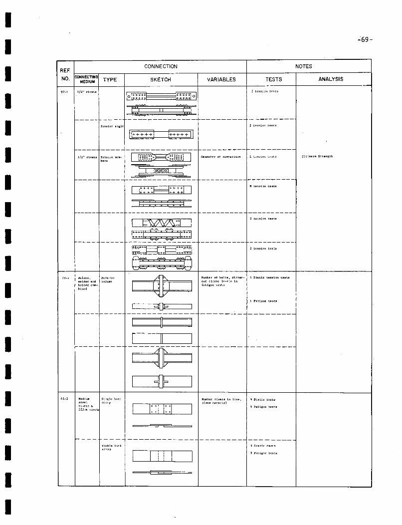
II
":69-
I REF
NO. CONNECTINGMEDIUM TYPE
CONNECTION
SKETCH VARIABLES TESTS
NOTES
ANALYSIS
II
97-1 1/2" rivets
f-----
Tension angle
Jer:: II ::c:[---------
2 tension tests
2 tension teSlS
I_____ --------------1----------1----------
1/2" rivets ~:~:10n mem- I [[(:.};:~;I¥fjJ I Getr.netry of connection 2 tension tests Ultimate Strength
-----I--~-----~-
----- 1------ ---------------- ---------- ----------2 tension tests
8 tension tests
1:::::::1
I
II
II
38-1 Welded. Beam-to-welded snd columnbolted com-bined
2 tension tests
Number of bolts, differ- 5 Static tension testseot stress levels infstigue tests
I ----------I SO? I
--------------
~
6 Fatigue teslS
-----------------
-- -- ------------- --------- ---------
IIIII
41-2
1-----1----
Medium Single buttsteel straprivets &:S35-W rivetl:
r----double buttstrop
L.......-_~L___-----3-----~4DIl__F-
O::i 1::0
OliO
Number rivets in line.plate material
9 Static teslS
9 Fl:!tigue tests
9 Static tests
9 Fatigue tests
II
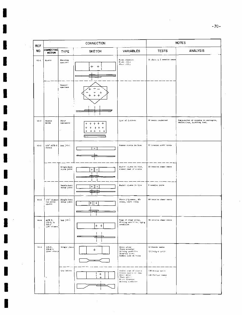
II -70-
f----f---- -
Tensionspecimen
--- ------------
ANALYSIS
NOTES
TESTS
16 shear &; 2 tension testsRivet dia:ne~er
Rivet H 110)'Pl;;,te illlo;'
VARIABLES
+ + "+ + 'I>+ + /'
"
SKETCH
CONNECTION
'-- 1_+__+_"------
==d=L~:=:3I
---~----
TYPE
Shearingspecimen
Rivets
CONNECTING. MEDIUM
42-1
REF
NO.
I
II
I
I"'VI !
i Ii I
I42-2 Rivets
WeldsPlatespecimens t + + + +
+ + + t ++ + + + t
Type of f,-,stener 18 tests conducted Computation of strains in stringers,deflections, buckling load,
I 43-1 liB" A17S-T Lap jointrivets
Number rivets in line 12 tension shear tests
I i,----r---- ---------- -------
t- i_ L _
~~~~~ej~~~~ I+ :: + Ic:LJ:;
II
Single';'buttstrap joint ~___--.J~L- _
I I
rt-±
Nllmher rivets in line,nllmber rows of rivets
Number rivets in line
20 tension shear tests
"-------8 tension tests
II
44-2 1/2" alumin- Single-butt Plate thickness. Dit 69 tension shear testsium alloy strap joint [£IE] ratio, rivet alloyrivets
[ !
tnTI I
44-4 AI7S-T, Lap joint Type of rivet alloy, 20 tension shear tests17S-T, Eo
l~driving condition, aging
24S-T condition1/8" rivets
I
f-----f----- ------1-------- -------
III
44-5 17S-T, Single plate53S-W &steel rivets
Lap joi:":ts
Rivet alloyPlate materialDriving conditionDiameter rivetNumber roloiS of holes
Numher r:lWS of rivetsNlImher rivets iel lineRivl't ,All:l\PLItt' All,'Ri F~ t d i "mE' t erDrivi:'lj: CHldi,i:'1l
15 Static tests
15 Fatigue tests
138 Static tests
13R FntigliE' r.ests
I
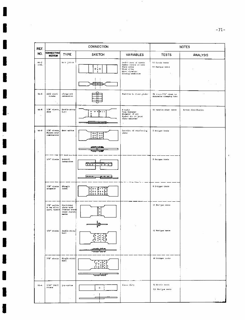
I1I1III-IIII1IIIIIII
-71-
REF.CONNECTION NOTES
NO. CONNECTINGTYPE SKETCH VARIABLES TESTS ANALYSISMEDIUM
44-5 Butt joints Number rows of rivets 93 Static testscont.
OEITJNumber rivets in linePlate alloy 93 Fatigue testsRivet alloyRivet diameterDriving condition
! !
~I I
44-6 A141 steel Flange-web m Position in plate girder 28 tests-JIS" rivet torivets connection determine clamping fore
44-8 7/8" rivets, Double-strap H width 55 tension shear tests Stress distributionpins butt =rrrL Type fastener+ I Diameter of pin
. . I Number pin in jointPlate material
44-9 7/8" rivets, Butt splice Location of reinforcing 9 Fatigue testsPillet-weld
IHiI+!1plate
combination ++11 ++++, ++
I :2Jo:2 I
1---- r----- ---------- ------- ------3/4" rivets Lateral
i+ +
8 Fatigue testsconnection
I 9 I+ i
100 n 2S n !
~--'- ~--~-----------1------- t-------7/8" rivets Shingle ~ ~ 6 Fatigue testsplugweld joint
I 111H!IHlil I~ ~
1---- --- ---_.,.----~--f-------'- ------7/8" carbon Continuous
DO12 Fatigue teats
& low alloy plate withsteel rivets riveted tran
verse attachments
~3/4" rivets Double-strap
r----\ ;-12 Fatigue tests
butt
$<i~1)+ ++1 ++-+ , +
L--....J '---
:223 3D---- ---- --------- r-------....:. -------
7/8" rivets Single-strap 18 Fatigue testsbutt
I (,<~~rrI + 1+ ...1"+++ + ~
I I000 000
Sheet alloy 15 Static tests45-4 3/16" 24S~T Lap splice
I I I
Irivets + II 252 Fatigue testa
Ii I
i
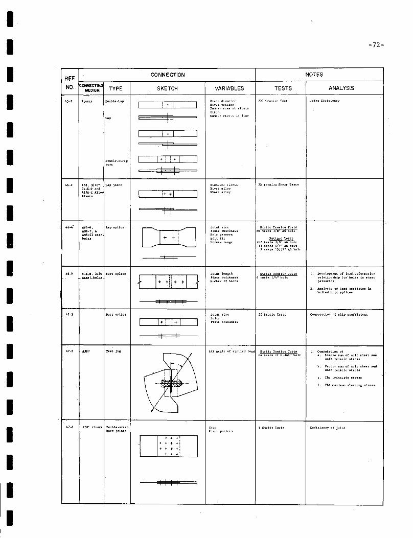
IIIIIIIIIIIIIIIIII
-72-
REF.CONNECTION NOTES
NO. CONNECTINGTYPE SKETCH VARIABLES TESTS ANALYSISMEDIUM
45-7 Rivets Double.U!p RLvet diameter 220 Tens ion Tes t Joint Efficiency
I ! + I I Rivet patternNumber rows of rivets
!PitchNumber rivets in line
Lap
I ! +- I III
Double-strap I 1+ ! ! + I Ibutt
q P46-2 1/8, 3/16", Lap joint Diameter rivets 25 Tension Shear Tests
24-6-T and Rivet alloyA178-T A110 I 1+ +1 I Sheet alloyI.ivets
I II I
46.4- AH6~6, Lap splice
0 jJ Joint size Static Tension TestsAN6.'·, 60 Plate thickness 60 tests 3/8" ,\6 boltAN6-11 teee Bolt patternbolt. + + Bolt fit
788 tes~:t~,~~ ~:8~~ltStress range11 tests 1/4" A6 bolt
7 tests 15/32" ,\6 bolt
I I
46-9 5.&.1. 2330 Butt splice Joint length Static Tension Tests 1. Development of load-deformation...... LI>nll4 0+ +·!l ++0 Plate thtctttTe1rr 6 tests 114" half relationship for· bolts in shear
Number of bolts (elastic) .
2. Analysis of load partition i.nbolted butt .plicel
I I I
47-3 Butt aplice Joint siZe 55 Static Tests Computation of aUp coefficient
1 1+ ! !+ I IBoltsPlate thickness
I I
47-5 AJ07 Tut jiB (A) Angle of applied load Static Tention Tests 1. Computation of64 tests of 0.369" bolt a. Simple aum of unit shear and
unit tenaile stress
b. Vector sum of unit shear and-, unit tenaile· stressII
The principle stress.d.. , c.
_.
;r d. The llIaximum 8~earing stunIII
-----0
47-6 7/8" riveta Double-strap Gage 6 Static Tests Efficiency of jointbutt joints Rivet pattern
, + +I, + + +'
+ + +,
"+ + +'
I I I I
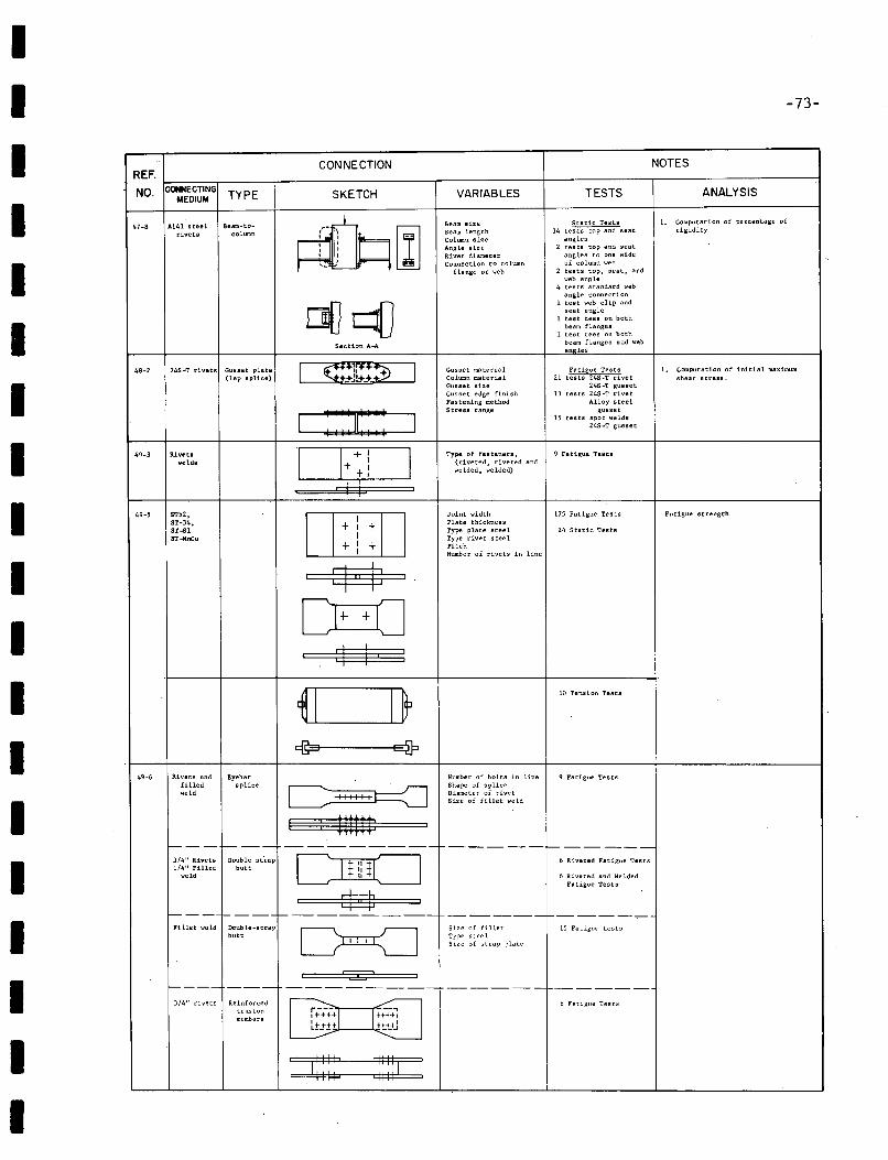
II -73-
ANALYSIS
1. Computation of percentage ofrigidity
NOTES
TESTS
Static Tests34 tests top and seat
angles2 teats top and seat
angles to one sideof column web
2 tests toP. seat, andweb angle
4 tests standard webangle connection
1 test web clip andseat angle
1 test tees on bothbeam flanges
1 test tees on bothbeam flanges and websooles
VARIABLES
Beam sizeBeam lengthColumn sizeAngle sizeRivet diameterConnection to column
flange or web
SKETCH
CONNECTION
TYPE
Section A-A
A141 steeL Beam-to-rivets column
..
REF. (..---.----.,-----------,---------f--------,-----------.,NO CONNECTING
. MEDIUM
II
II
Joint width 17S Fatigue TestsPlate thicknessType plate steel 24 Static TestsType rivet steelPitchNumber of rivets in line
IIIII
48-2 24S-T rivets Gusset plate(lap splice)
Rivetswelds
5T52,5T-34,5T-51ST-HnCu
I ::::~: ::: I
DL+_+..;.+~! I! i
I+ I +I
+ : +
=¢=
~j : I I, :
Gusset materialColumn materialGusset sizeGusset edge finishFastening methodStress range
Type of fasteners,(riveted, riveted andwelded, welded)
Fatigue Tests21 tests 24S-T rivet
245-T gusset13 tests 24S-1 rivet
Alloy steelgusset
15 tests spot welds24S·T gusset
9 Fatigue Tests
1, Computation of initial maximumshear stress.
Fatigue strength
III
49-6 Rivets and Eyebarfilled spliceweld
<:@::3t-----q}
C -++++++1
I : .:===Number of bolts in lineShape of spliceDiameter of rivetSize of fillet weld
10 Tension Tests
9 Fatigue Testa
Fillet weld 15 Fatigue testsSize of filletType steelSize of strap plate
6 Riveted and We ldedFatigue Tests
6 Riveted Fatigue Tests
---------I-----~
-----1------Double st·rap
butt3/4" Rivets1/4" Fillet
weld
f---I----- ---------
C)mCJ$$I
III
f----- --- -------------- ----------
3/4" rivets Reinforced !l Fatigue Teststension
i+4-;~1 -I t+++~memberst±+.±+ ttt_+J
: I:::: : :::::1 :
I
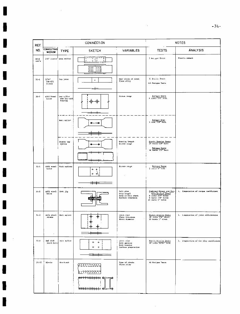
IIIIIIIIIIIIIIIIIII
-74-
CONNECTION NOTESREF.
NO. CONNECTINGTYPE SKETCH VARIABLES TESTS ANALYSIS
MEDIUM
49·6 3/4" rivets Beam splice 0: +1f+ :tJ 3 Fatigue Tests Plastic, moment
conlt + II ...._ JL_ -
I l~t+"++11 I:+;i!:~~
50-1 3/16" lap joint I ! + I I Head style of rivet 11 Static Tests
245-T31 Plate alloy
rivets 124 Fatigue Tests
I
50-7 A325 Steel Lap splice
03JStress range Fatigue Tests
bolts and lap with 4 tests 718" boltbracing
I I-----1---------- ---- ------- '--------
Ci--O Fatigue TeatButt splice1 test 718" bolt
4 I.~--- ------- - -- - --- --- -------
Double lep
CI~i:JBracing length Static Tension Tests
splice Stress range 22 tests 718" bolt
Fatigue Tests30 tests 7/8" bolt
D : : 051-1 A325 steel Butt splices Stress range Fatigue Testa
bolts D: :\1 I2 tests 1" bolt
I I
51-2 A325 steel Test jig
~Bolt size Combined Direct and Tor- 1. COIII.putat1on of torque coefficient
bolta Grip length qued Tension TeatsArea of bolt shank 8 tests 3/4il boltsSurface treatment 8 tests 7/8" bolts
22 tests 1" bolts
51-3 A14l steel ~utt splice
DOJJoint size Static Tension Tests 1. Computation of joint efficiencies
rivets Plate thickness 16 tests 3/4" rivetRivet diameter 16 tests 1" rivet
I I
D51-6 SAE 4140 Butt splice
+ +
i IJoint size Static Tension Tests 1. Computation of the slip coefficient
Steel bolt Bolt pattern 18 tests 63/64" boltBolt tension
+ + Surface preparation
I I
51-12 Rivets Box-beams Type of rivets 40 Fatigue Tests
~~~~~~~:~~ .
Plate alloy
=+~:.-+-+-.~
OII
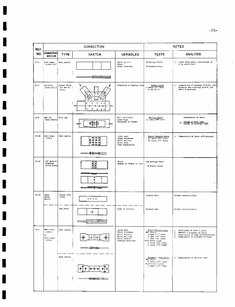
IIIIIIIIIIIIIIIIIII
-75-
CONNECTION NOTESREF.
NO. CONNECTING TYPE SKETCH VARIABLES TESTS ANALYSISMEDIUM
52-5. A141 steel Butt splice
IRivet pattern SO Fatigue Tests 1. Joint efficiency, coefficient of
I,
Irivets 3/4" I Pitch slip coefficient
J Rivet location 19 Tension Tests,
52-6 Alwninum Gusset Plate "- n I Direction of applied load Static Tests 1. computation of maximum tensile, com.-Alloy b.otts for Warren 2 tests 1/4" bolt presslve and shearing stress. and
Truss / 61-ST plate their directions.
.~' ,0 0: <~1.o 0' I I /0, 0,0 0...>,0° 1(,)( 0,
-F'.:'" 19.,PJ ~/
1---------o 0 0 0 0
-----...- -...........-o 0 0 0 0
52·9 BSF 511 Test jig Bolt pretension Fatigue Teats Computation' of a.atl0Steel Bolts +C§tfEJ ]-
Load range 17 tests 374" boltThickness of ....ssher of
Change 1n bolt loadChange in external load
52-10 Al41 steel Butt splice
DmJJoint size Static Tension Teats 1. Computation of joint efficlenc1e1
rivets Plate thickness 12 tests 718" rivetRivet pattern 24 tests 3/4" rivetRivet sizeTest temperature
I I I
52-17 1/8" AL7S-T3
I a§ IPitch 190 Fatigue Tests-- Number, of rivets in line
Alloy RtvetJ 34 Static Tests
=-=
D ; I IIJ
I
52-19 Pin, Plates '-'ith Tension test Stress concentrationsBolts holes I IRivets o 0 o 0
- '--- --- - ---_.- -- -- - --Lap joint
D I
IType of fastener Tension test Stress concentrations
+ I!
.1 q I :53-4 NR6 steel Butt splice Joint size Static Tension Test 1. Partitions of load in joint
rivets Plate thickness NR6 rivets 2. Overall elongation of joint
0' tt:J+i!+G]Rivet diameter 8 test 3/4" rivet 3. Computation of loss of efficienciesRivet material ij test 1/2" rivet 4. Computation of ultimate strength
Mild steel Rivet pattern 1 test 1/4" rivetrivets Loading condition Mild steel rivet
2 tests 3/4" ~ivet6 tests 1/2" rivet
I I---- --- - -- ---
Butt splice Eccentric Load Tests 1. Computation of failure loadsNR6 rivets
ij tests 1/2" rivet
[iliJ+++1Mild steel rivets
~9 tests 1/2" rivet
. ,
I I I
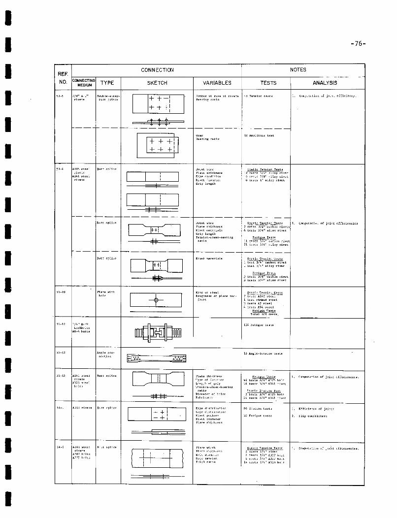
II -76-
Number of rows of rivets 4~ Tension testsBearing ratio
--------_.-
IIIII
CONNECTIONREF.
NO. CONNECTING TYPE SKETCHMEDIUM
53-5 7/B" & 1" Double-strap- D+++:I'
rivets butt joints
+ -t +1I
$$$=f---- t--------.-
1+ ++: I++ +:I
53-9 A195 steel Butt splicerivets 0A141 steelrivets
VARIABLES
GageBeilring ratio
Joint sizePlate thicknessEdge conditionRivet diameterGrip length
TESTS
l~ Amplitude test
Static Tension Tests12 tests 3/4" alloy rivet
6 tests 7/8" alloy rivet6 tests 1" alloy rivet
NOTES
ANALYSIS
1. Computation of joint efficiency.
f- ----1-----------.------ ------ --. - -- -- - _
I--- 1---_.- --- -----.---1---- -.--.. - -------- _
IIIII
53-10
53-12 1/4" HuckLockbolts
AN-4 butts
Butt splice
Butt splice
Plate withhole
D
CEI=:=JII
+
Joint sizePlate thicknessRivet materialsGrip lengthTens ion -5 hear-bea r1 ugratio
Rivet materials
Kind of steelRoughness of plate sur
faces
Static Tension Tests 1. Computatiuu of joint efficiencies2 tests 3/4" carbon rivets4 tests 3/4" alloy rivet
Fatigue Tests11 tests 374" carbon rivet21 tests 3/4" alloy rivet
Static Tension Tests1 test 3/4" carbon rivet1 test 3/4" alloy rivet
5 tes~:t~n~ ~::~:n rivet5 tests 3/4" alloy rivet
Static Tension Tests7 tests A242 steel1 test rimmed steel3 tests A7 steel4 tests A94 steel
Fatigue TestsTotal 109 tests.
114 Fatigue tests
53-15 A14l steel Butt splicerivets
A325 steelbolts
54-1 A14l rivets Butt splice
Fatigue Tests 1. Computation of joint efficiencies.46 tests 3/4" A325 bolt98 tests 3/4" Al4l rivet
I
IIII
53-13
54-2
Angle connection
A141 steel Butt splicerivets
A307 boltsA325 bolts
S3§'=====~::;;pflj.
cnr=J'"""
{±+±D
Plate thicknessType of fastenerLength of gripTension-shear -bearingratio
Diameter of holesFabricator
Edge distributionGage distributionRivet patternRivet diameterPlate thickness
Plate widthPlate thitkressBolt diameterBolt tensionT:S;B ratio
18 Angle-tension tests
Static Tension Test3 tests 3/4" A325 bolt
21 tests 3/4" A14l rivet
96 Tension tests
32 Fatigue tests
Static Tension Tests2 tests 3/4" rivet2 tests 3/4" A307 bolt4 tests 7/8" A307 bolt
14 tests 3/4" A325 bolt
1. Efficiency of joints
2. Slip coefficient
I, Computation of joi'nt efficiencies,
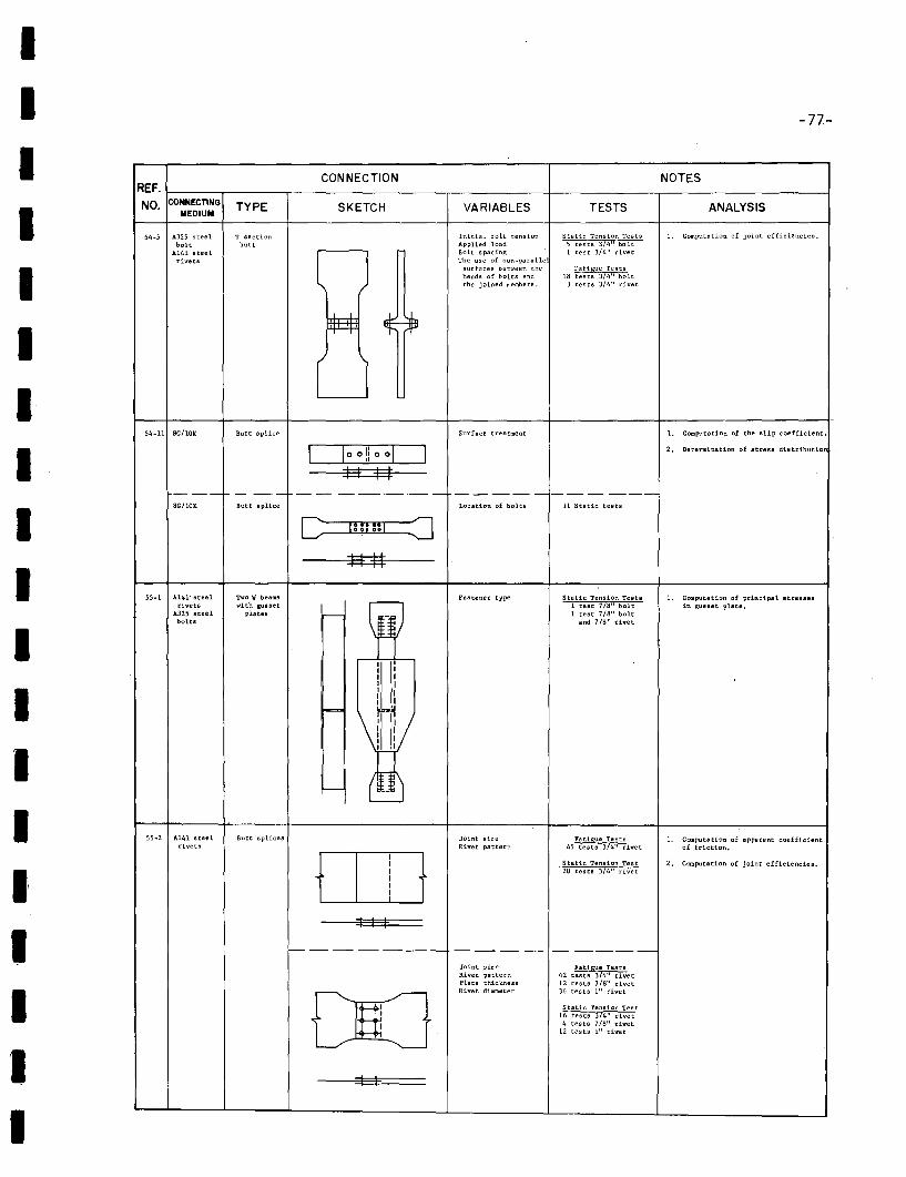
IIIIIIIIIIIIII
IIII
-77-
CONNECTION NOTESREF.
NO. CONNECTING TYPE SKETCH VARIABLES TESTS ANALYSISMEDIUM
54-5 A325 steel T section Initial bolt tension Static Tension Tests 1. Computation of joint efficiencies.bolt butt Applied load 5 tests 3/4" bolt
A141 steel
l JBolt spacing 1 test 3/4" rivet
rivets The use of non-para liesurfaces between the Fatigue testsheads of bolts and IS tests 3/4" boltthe joined memhers. 3 tests 3/4" rivet
~
r I54-11 Bc/lOK Butt splice Surface treatment 1. COlIIputation of the slip coefficient.
CJoo!iooD 2, Determination of stress distribution
I I I I--- - -- -- ---'--._- -----------SCIlOK Butt splice Location of bolts 11 Static tests
C Im::1 ::=J##
55-1 A141· steel Two 'i beams Fastener type Static TensiOn Tests 1. Computation of principal strene.rivets with gusset 1 test 718" bolt in gusset plate.
A325 steel plates -U
1. test 7/8" boltbolts snd 7/8" rivet
I
~II II II II I-!IV
- t~
S5~2 A1.41 stee1. Butt splices Joint size Fatigue Tests 1. Computation of I!lpparent coefficientrivets Rivet pattern 45 tests 37411 rivet of friction.
0I
tI Static Tension Test 2. Computation of joint efficiencies.I 20 tests 3/4" rivetIIII
I I I
f---- -- -- ----- ----- -- - ----Joint size Fatigue TestsRivet pattern 42 tests 374" rivetPlate thickness 12 tests 7/8" rivet
00Rivet diameter 36 tests 111 rivet
Static Tension Test16 tests 374" rivet4 tes ts 7/8" rivet
12 t~sts 1." rivet
I I
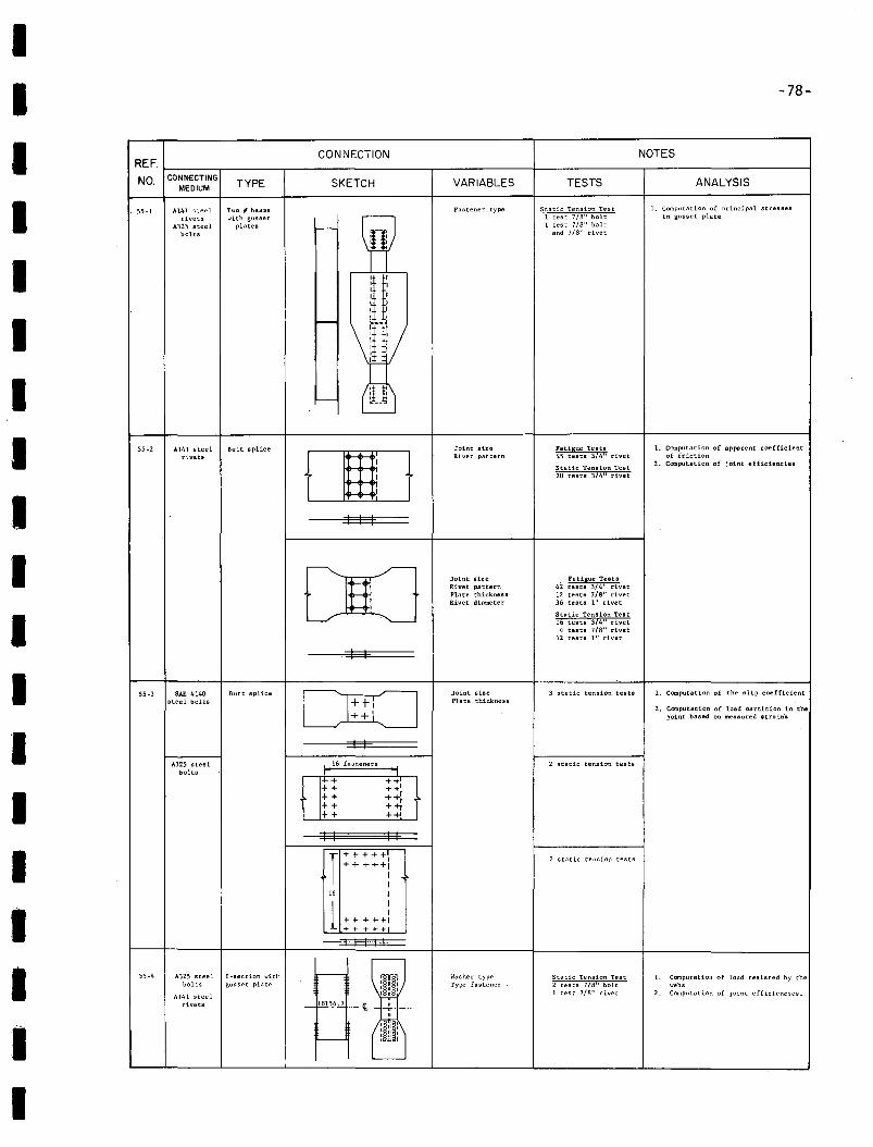
II -78-
I CONNECTION NOTESREF.
NO. CONNECTINGTYPE SKETCH VARIABLES TESTS ANALYSIS
MEDIUM
I 55-1 A141 ":teel Two 'yf beams Fastener type Static Tension Test 1. Complltation of principal stresses
rivets with gusset
\W1 test 7/8" bolt in gusset plate
A325 steel plates >-- 1 test 7/8" bolt
bolts and 7/8" rivet
I nI
~ ~~~'
lIt!I I-- ~__E
I 55-2 A141 steel Butt splice
[][]Joint size Fatigue Tests 1. Computation of apparent coefficient
rivets Rivet pattern 45 tests 3/4" rivet of friction
Static Tension Test2. Computation of joint efficiencies
20 tests 3/4" rivet
I I I I
I DO Joint size Fatigue TestsRivet pattern 42 tests 3/4" rivetPlate thickness 12 tests 7/8" rivetRivet diameter 36 tests 1" rivet
IStatic Tension Test16 tests 3/4" rivet4 tests 7/8" rivet
12 tests 1" rivet
I I
I 55-3 SAE 4140 Butt splice Joint size 3 static tension tests L Computation of the slip coefficient
steel bolts DO Plate thickness
++'2. ComputatiOn of load partition in the
joint based on measured .train".
I I IA325 steel 16 fasteners 2 static tension tests
bolts
++ ++++ ++1
I ++ ++i++ ++r++ ++'
I I I I
I T+++++' 2 static tension tests
+++++!
16 I
I 1 II
+ + + +-+1+ + + + +
I I I I
I 55-4 A325 steel I-section witl' ,...----,
rmlWasher type Static Tension Test 1. Computation of load resisted by the
bolts gusset plate1
Type fastener 2 tests 7/B" bolt webs
Al41 steel1 test 7/B" rivet 2. Computation of joint efficiencies.
rivets - jill'_42I-~ ".-"
I~ :~'t"----If : ~ :
I
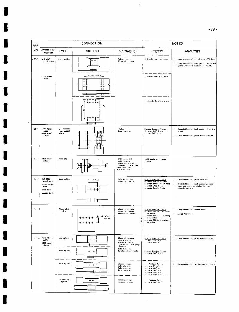
IIIIIIIIIIIIIIIIIII
-79-
CONNECTION NOTESREF.
NO. CONNECTING TYPE SKETCH VARIABLES TESTS ANALYSISMEDIUM
. 55 ..3 SAE 4140 Butt splice DO Joint size 3 Static Tension tests 1. Computation of the slip coefficient.steel bolts Plate thickness
++' 2. computation of load partition in thejoint based on measured strains.
I I1----------- ------A325 steel I
16 fastenersI 2 Static Tension tests
bolts
1:1:::: ++1++,++ ++,++ ++,++ ++,I I II
f- --- ----- ------T+++++: 2 Static Tension tests+++++,II
16 II
1t++~t!I I I I I
55-4 A325 steeL I - section Washer type Statlc Tension Tests 1. Computation of load resisted by thebolts with gusset ,....--
rnrr:Type fastener 2 tests 7/8" bolt webs.
A141 steeL pLate 1 test 7/8" rivetrivets 111 1 2. Computation of joint efficiencie••
- --- f-- "..~
rn',~~I ~ I
55 ..5 A325 steel Test jig
~~Bolt diameter 1200 tests of single
bolts Bolt length boltsAir-pressure of
pneumatic wrenchesTime intervalNut rotation
55-9 SAE 1020 Butt splice no. varies Bolt materials Static Tension Tests 1. Computstion of joint modulus.steel bolt· Number of bolts 4 tests SAE 1020 bolt
Brass 60/40 oen 4 tests brass 60/40 bolt 2. Computation of load carrying capa-
bolt 4 tests 24ST bolt city and load partition in the4 tests lucite bolt elastic region.
245T bolt
Lucite bolt
I I I I
55-12 Plate with Plate materials Static Tension Tests L Computation of stress ratioholes Number of ho les 29 tests hot rolled steel
Pattern of holes no holes 2. Limit AnalysisNo, of holes 11 tests hot rolled steel
+++++ ] varies with holes
++++ 6 tests 61S-T6 aluminum
+++++ no holes
55-14 A325 steel Lap splice
D+I
I Plate thickness Static Tension Tests 1. Computation of joint efficiencies.bolts +: Bolt diameter 32 tests 3/4" bolt,
Number of holes 12 tests 3/4" boltA14l steelI I C/?ntact surface prep-rivets f-- - - t--- ---- - -- aratton
C]+I
IBolt Tension
Butt splice + Tension-shear ratio Static Tension Tests,12 tests 3/4" bolt,
I II-- -- 1------- --- '- --- - - - ---- 1-----------
Butt splice
~Stress range Fatigue Tests 1. Computation of the fatigue strengthBolt diameter 35 tests 1" boltBolt tension 5 tests 7/8" bolt
I IType fas tener 3 tests 5/8" bolt
3 tests 3/4" bolt1-'--- -- ---- ---- - l-- - -- - - f-- L!:.s!:!..l../8~v:.E....- _
Double-lap C 1++: -=:J Loading ranKe.1 te~~~i~/:}:*splice ~racinF ler:gth
\ a \
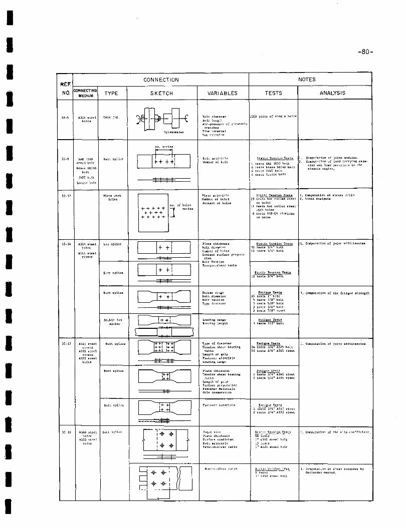
IIIIIIIIIIIIIIIIIII
-80-
CONNECTION NOTESREF.
NO.CONNECTING
TYPE SKETCH VARIABLES TESTS ANALYSISMEDIUM
55-5 A325 steel Test jig
~Bolt diameter 1200 tests of single bolts
bolts Bolt lengthAir-pressure of pneumatic
wrenches
Dynamometer Time interva 1Nut rotation
no, varies
55-9 SA! 1020 Butt splice oen Bolt materials Static Tension Tests l. Computation of joint modulus.
steel bolt Number of bo 1 t 4 tests SAE 1020 bolt2. Computation of load carrying capa-
Brass 60/40 4 tests brass 60/40 boltcity and load partition in the
bolt 4 tests 245T boltelastic region.
245T bolt4 tests lucite bolt
Lucite bolt I I I I
55 ~ 12 Plate with Plate materials Static Tension Tests 1. COIIIputation of stress ratio
holes Number of holes 29 tests hot rolled steel 2. Limit Analysis
of holesPa ttern of holes no holes
no. 11 tests hot rolled steel+++++ ] varies with holesr+++ 6 tests 61S-T6 aluminum
+ + +++ no holes
55-14 A325 steel Lap splice 0+ +1 IPlate thickness Static Tension Tests 1. Coniputation of joint efficiencies
bolts Bolt diameter 32 tests 3/4" bolt
A141 steelNumber of bolts 12 tests 3/4" boltContact surface prepara-
rivets I I tionBolt Tension
0+ +1 ITension-shear ratio
Butt splice Static Tension Testa12 tests 3/4" bolt
I I
Butt splice
~Stress range Fatigue Teats 1. 'COIItfJUtation of the fatigue strengthBolt diameter 35 tests 1" boltBolt tenaion 5 tests 7/8" boltType fastener 3 tests 5/8" bolt
I I 3 teats 3/4" bolt3 tests 7/8" rivet
Double lap C 1++1 :J Loading range Fatigue Testssplice Bracing length 3 tests 7IS" bolt
\ I I \
55·17 Al41 steel Butt splice [JillJTI(J Type of fas tener Fatigue Tests 1. Computation of joint efficienciesrivets ++1 1++ Tension shear bearing 24 testa 3/4" A325 bolt
A195 steel ++1 1++ ratio 56 tests 3/4" A141 rivetrivets Length of grip
A325 steel un Fastener materialsbolts Loading range
Butt splice
DOPlate thickness Fatigue TestsTension shear bearing 5 tests 3/4" Al41 rivet
ratio 7 tests 3/4" A195 rivetLength of gripSurface preparation
I IFastener MaterialsHole preparation
Butt splice
~Fastener materials Fatigue Tests
++ 2 tests 3/4" A14l rivet2 tests 3/4" A195 rivet
I I55-18 4140 steel Butt splice j i: :0 Joint size Static Tension Tests 1. Computation of the slip coefficient.
bolts Plate thickness 48 testsA325 steel Surface condition tt' 4140 steel bolt
bolts Bolt materials 13 testsTension-shear ratio 1" A325 steel holt
I I
4- I 0Moment-shear ratio Sl1ltic Torsion rest 1. Computation of shear stresses by.- 6 tests Gullander method.
II 1" 4140 steel bolt
I4- 4- I, I
I
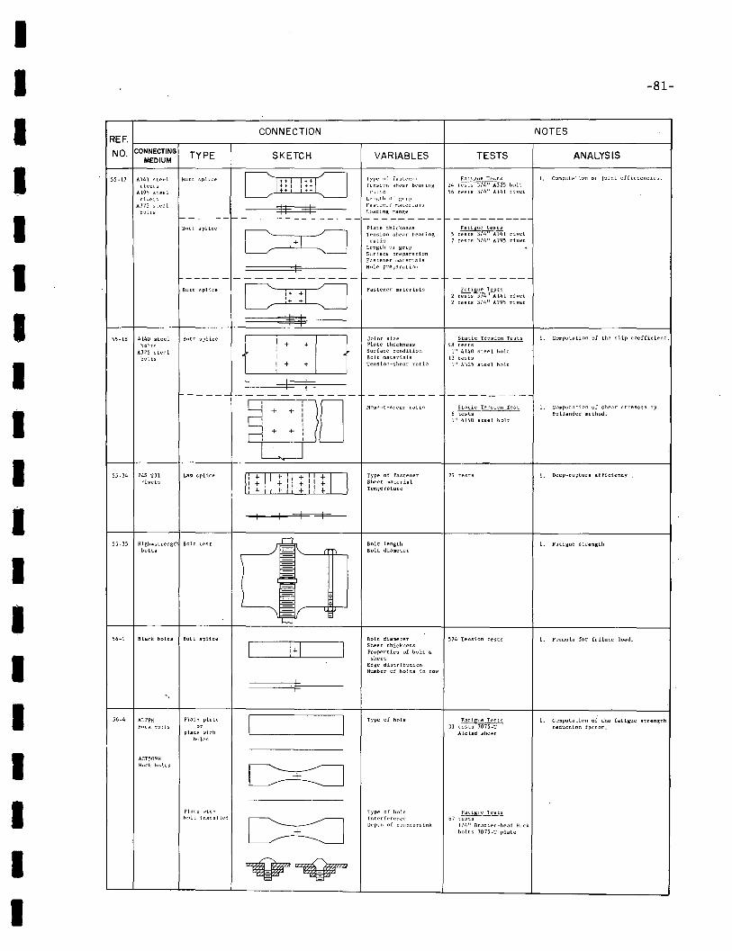
II -81-
ANALYSIS
I. C~;npllu'·".on of joint efficiencies.
1. Deep-rupture efficiency
1. computation of shear stresses byBullander method.
1. Computation of the slip coefficient.
NOTES
TESTS
Static Tension Test6 tests1" 4140 steel bolt
Fatigue Tests2 tests 3/4" A141 rivet2 tests 3/4" A195 rivet
--------
Fatigue tests5 tests 3/4" A141 rivet7 tests 3/4" A195 rivet
27 tests
Fn::l,I~lle Tests24 tC5i:7)~:rr5 bolt50 tests 3/t," A141 rivet
Static Tension Tests48 tests
1" 4140 steel bolt13 tests
1" A325 steel bolt
VARIABLES
Fastener materials
Type of fastenerSheet materialTemperature
Moment-shear ratio
Joint sizePlate thicknessSurface conditionBolt materialsTension-shear ratio
SKETCH
CONNECTION
t II t :It: I t
----------------
~::\ 10I I
Plate thicknessTension shear bear ingratio
Length of gripS\lrface preparationFastener materials
I Hole prep9.riltion
-----------------f-------
~I I
Lap splice
Butt splice
Butt splice
Blltt splice
Butt splice D i! 0 Typl' ~)i fa"te:~er1:! I:: 'j'~::~~I~ ~hear bearin~LI'Il!';t!J of grip
II II ~~:~~~~r r:~~:rials----------------------------------------
4140 steelbolts
A325 steelbolts
A141 steelrivets
A19S s::eelrive:s
A325 s~eel
bolts
55-34 245-131rivets
55-Hl
55-17
REF. j----.----,-------------,-------I-------r--------------jNO. CONNECTING TY PE
MEDIUM
II
I
II
I
II
III
5S-3S High_strengt Bolt testbolts
Bolt lengthBolt diameter
1. Fatigue strength
IS6-1 Black bolts Butt splice
__--'1_+1 _Bolt diameter 574 Tension testsSheet thicknessProperties of bolt &;
sheetEdge distributionNumber of bolts in row
1. Formula for failure load.
II
-.
56-4 ALPP\-IHlick h~lts
ACT509HHuck holts
Plain plate
"'plate withholes
Type of hole Fatigue Tests31 tests 7075-T
Alclad sheet
1. Computation of the fatigue strengthreduction factor.
II
Plate \-"ithh:llt in~Hal ted
Type of holeIr.terferenceDepth of cO\lntersink
!'..atigul' T~~~67 tests
1/4" Brazier-head Huckbolts 707S-T plate
I
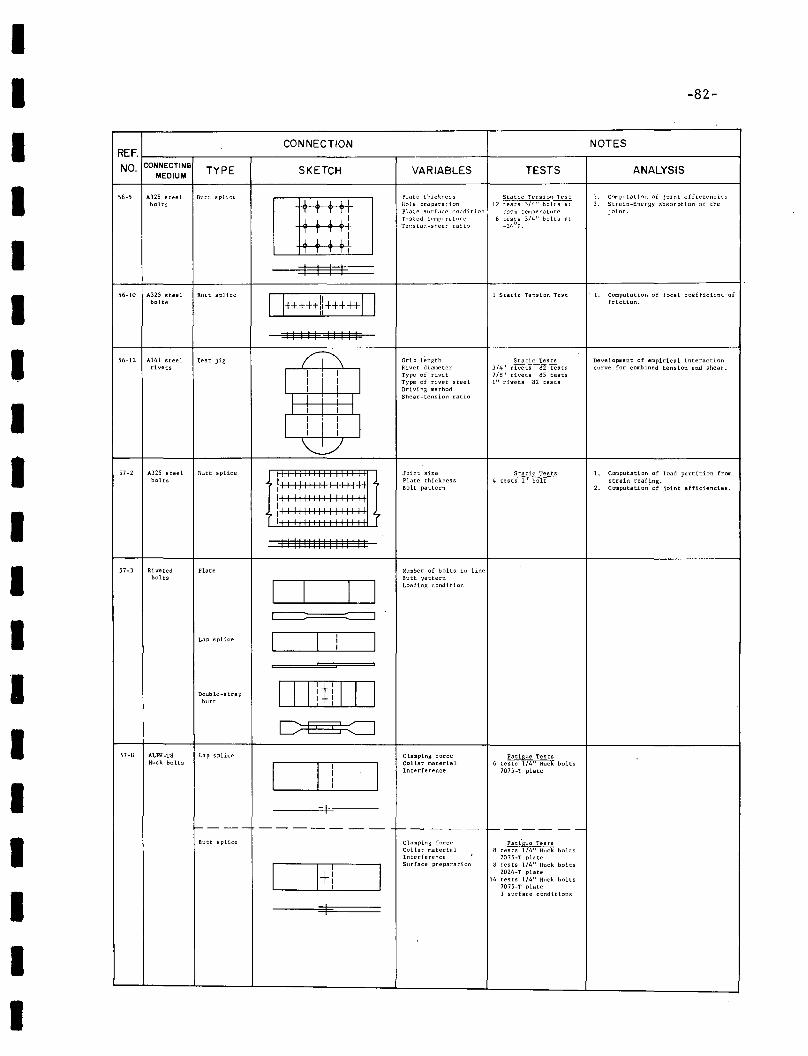
IIIIIIIIIIIIIIIIIII
-82-
CONNECTION NOTESREF.
NO. CONNECTINIOTYPE SKETCH VARIABLES TESTS ANALYSIS
MEDIUM
56-5 A325 steel Btl::: splir:e
[8]Plate thickness Static Tension Test l. c~putati::ln of joint efficiencies
bolts Hole prepara~ion 12rest~1~ ,. Strain-Energy absorption of thePlate surface cor.ditian room temperature joint.Tested temperature 6 tests 3/4" bolts atTe\:sion-she<Jr ra~i';) -24°F.
I I I I56-10 A325 steel 1 Static Tension Test l. Computation of local coefficient ofBult splice
0+++++1:+++++0bolts friction.
II I I I II I II
56-12 A141 steel Test jig iI\ Grip length Static Tests Development of empirical interactionrivets Rivet diameter 3/4" rivets 82 tests curve for comb ioed tens ion and shear.
I I
iI
IType of I:"ivet 7/8" rivets 85 tests
I I Type of rivet steel 1" rivets 82 teats
I I Drivin6 methodShear-tension ratio
I I I I I
II
iI
II II I
~
57-2 A325 steel Butt splice Joint size Static Tests L Computation of load partition frombolts ill 1I111I11111111
Plate thickness 4 tests 1" bolt strain read~ng.
Bolt pattern '. Computation of joint efficiencies.
III 1111II11 I11I11
ill I1I11111 II1I11I
II II1III1 I 1111 II
57-3 Riveted Plate Number of bolts in linebolts Butt pattern
D [J Loading condition
I I
Lap splice I II
I1I
Double-strap OJJID]Jbutt 1+ i
C PS ::::::::J57-8 ALPH-T8 Lap splice Clamping force Fatigue Tests
Huck bolts
I II
ICollar material 6 tests I/4" Huck bolts
IInterference 7075·T plate
II
I---- ----- ---- ----- 1---- --
Butt splice Clamping force Fati'gue TestsCollar material 8 tests 114" Huck boltsInterference 7075-T plate
I I+l ISurface preparation 8 tests 1/4" Huck bolts
2024-T plate14 tests 1/4" Huck bolts
7075-T plate3 surface conditions
I
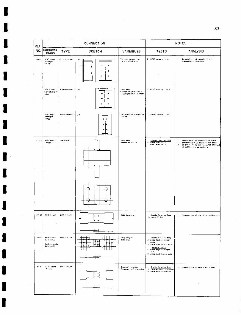
IIIIIIIIIIIIIIIIIII
-83-
CONNECTION NOTESREF.
NO. CONNECTING TYPE SKETCH VARIABLES TESTS ANALYSISMEDIUM
57-12 5/8" high- Direct-Moment- '.,U IT]Varying c:>nnection Z-8WFZO bending test 1. Computation of moments 'com
strength plate thickness theoretical equations.
bolts
5/8 & 7/8" Direct-Moment- (8)
IT]Bolt size 2 8WF17 bending t~sts
high-strength Change in geometry &bolta eccentricity of bolts
718" high- Direct-Moment- (C)
rnVariation in number of I-lBWFSO bending test
strength boltsbolts
57-14 A325 steel T-section n Bolt size Static Tension Test 1. Development of interaction curvebolts Number of bolts 5 tests 718" bolt for -strength in tension snd shear.
1 test 5/8" bolt 2. Computation of the ultimate strengtl
Iof bolted tee connection.
I
I i~ r+-
L-..-
I
- ·-r -
- -t- --K- l-
I
57-15 A32S bolts Butt splice DLJ Bolt tension Ststic Tension Test 1. Computation of the 51 ip coefficient26 tests I" bolt
+ +'
I I51-16 Hook·Knurl Butt splice
~S'tatic Tension TestGrip length
A325 bolt Bolt type 3 tests high-strength
-- I -- boltsHigh tensile
_. I Ii' , " --
3 tests Hook-knurl boltbolt A325
Fatigue TeRts4 tests high-strength
bolt
I8 tests Hook-knurl bolt
I
57-L7 A325 steel Butt splice Internal tension Static Tension Test 1. Computation of slip coefficient.bolts Frequency of vibration 29 tests without vibratio
D: :! J33 tests with vibration
I I
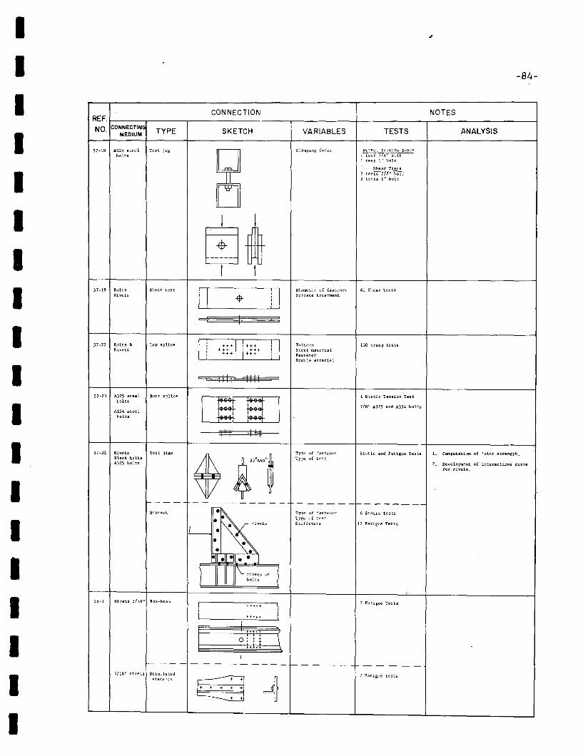
IIIIIIIIIIIIIIIIIII
-84-
CONNECTION NOTESREF.
NO. CONNECTINGTYPE SKETCH VARIABLES TESTS ANALYSISMEDIUM
57·18 A325 steel Test jig Clamping force Direct Tension Testsbolts 1 test 778" bolt
1 test 1" bolt
Shear Tests2tes~t2 tests 1" bolt
I I
~ t! I
57-19 Bolts Shear test
0 j IDiameter of fastener 61 Shear Tests
Rivets -+ Surface treatment
: I
57-22 Bolts 6. Lap splice
I,
H+ IH+ i IPattern 130 creep tests,
Rivets, +H +++ Sheet material: +++ H+ Fastener
Double material
IIII IIII
57-23 A325 steel Butt splice
[E 8J1 Static Tension Test
bolts7/8" A325 and A354 bolts
A354 steelbolts
III III
57-32 Rivets Test jigs
~~,o,••~
Type of fastener Static and Fatigue Tests l. Computation of joint strength.Black b.olts Type of testA325 bolts 2. Development of interacti.ons curve
for rivets.
1--- - - ------- - - - -----f-- ------Bracket
~~.Type of fastener 6 Static Tests
IL- •.• · rivet,
Type of testStiffeners 12 Fatigue Tests
• •• •• • • • I
) \.. rivets or
?bolts
58-1 Rivets 3/16" Box-beam 7 Fa tigue Tes ts
It+t++
)+++++
I in:: (\
I
f--- - - - - - - -- ---- f- -- - - - - - --3/16" rivets Stimulated - 7 Fatigue Tests
elements r- + +1
~+ + + + +
~
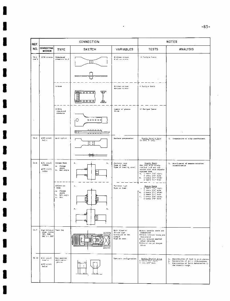
II -85-
I CONNECTION NOTES
1---- -~- ------ --
I-Beam
-----
ANALYSIS
- ---~-
TESTS
17 Fatigue Tests
4 Fatigue Tests
12 Fatigue Tests
--------
VARIABLES
Mini.mum strc;;sMaximum stress
Minimum st ressMaximolffi stress
Number of platesPitch
o
SKETCH
orE 0000001
--- - -------
TYPE
I-Beamsimulatedelements
CONNECTINGMEDIUM
58-1 3/16 rivets Simulatedcon't elements No.2I
I
I
II
II
58-2 A325 steelbolts
Butt splice
Ii: :: :: : :1
I I
Surface preparation Static Tension Test35 test 1" bolt
1. Computation of slip coefficient.
58-4 A141 steel Column Baserivets .. Flange
A325 steel angle
bolts b. Web angle
High-tensUe Test jigsteel boltsBSF, BSW,UNC and UNF
L Development of moment-relationrelationships
1. Distribution of load to pull plates.2. Computation of joint efficiencies.3. Computation of joint deformation in
the elastic range.
Static Tests2 tests 3/4" rivet2 tests 3/4" bolt
b. 2 tests 3/4" rivet2 tests 3/4" bolt
c. 2 tests 3/4" rivet2 tests 3/4" bolt
Static TestsOne test with slowlyapplied Joad and thesecond test with rapidlyapplied Load8. '3 tests 3/4" rivet
2 tests 3/4" boltb. 2 'tests 3/4" rivet
2 tests 3/4" bolt
Direct tensile tests aresummarized
Torqued tension tests, aresumllarized
Direct tension appliedafter torquing
Repea::ed torque ten~on
tests
Fastener typeType of loadType of loading steel
Fastener typeType of load
Bolt diameterThread typeCondition of NutLengthType of test
Specimen configuration Static Tension Tests2 tests 3/4" rivetI test 3/4" bolt
b.
161,I I, ,
.. lie:: i I=--~-----'Ir w-- !
s. Flangeangle
b. Web anglec. Tee
Column-tobeam
Box sectionwith batten
plates
1-------
A325 steelbolts
5~-12 A14l steelrive'';
58-7I
I
I
I
I
I
I
I
I
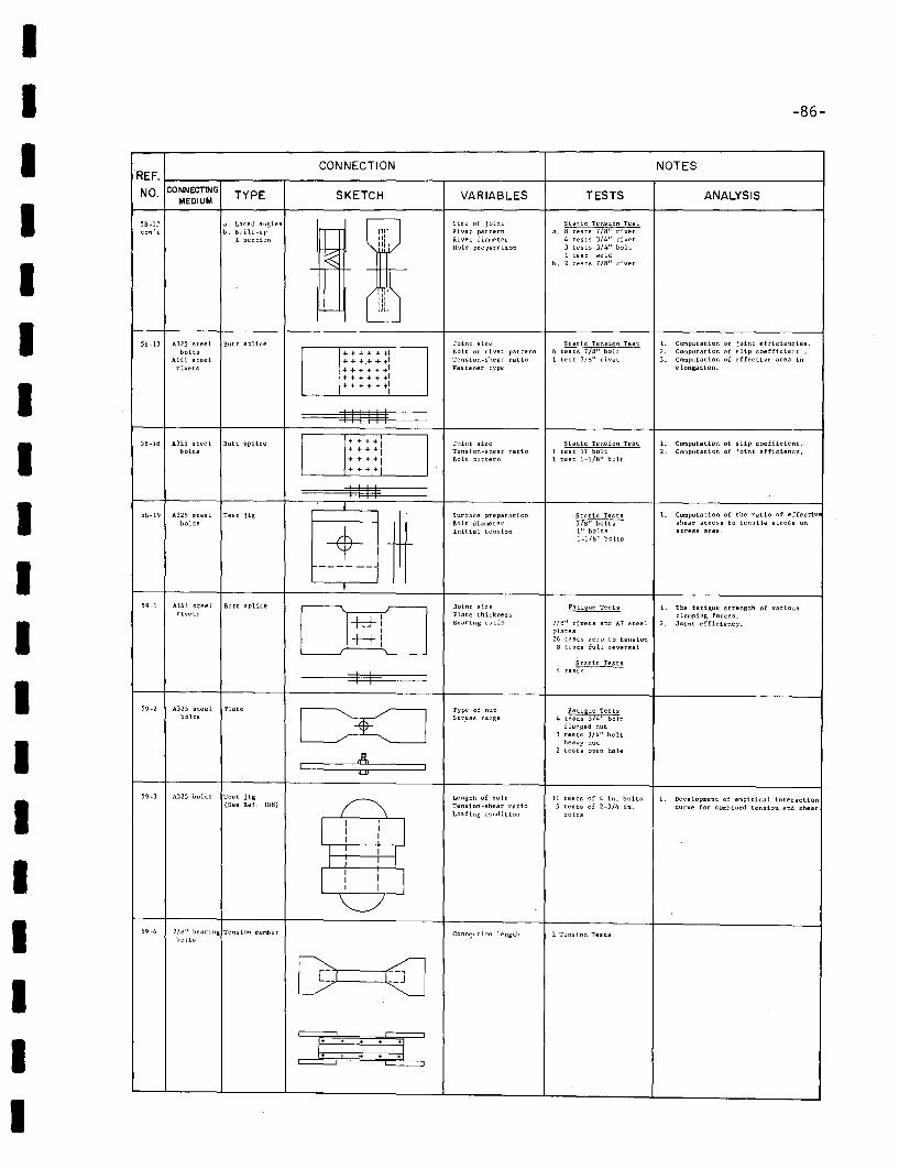
II -86-
ANALYSIS
1. Computation of joint efficiencies.2. Computation of slip coefficient.3. Computation of effective area in
e 100gat100•
NOTES
TESTS
Static Tension Test6 tests 7/8" bolt1 test 7/8" rivet
Static tension Testa.~"rivet
4 tests 3/4" rivet3 tests 3/4" bolt1 test weld
b. 2 tests 7/B" rivet
VARIABLES
Size of jointRivet patternRivet diameterHole preparation
Joint sizeBolt or rivet patternTension-shear ratioFastener type
'1'1::ll
IIIII1
++++++1+++ +1.... + of. +1+ + + + t +1+ + + + +- t l
I
SKETCH
CONNECTION
-
I.:-~
58-13 A32S steel Butt splicebolts
A141 steelrivets
58-I? a. Laced anglescan't b. Built-up
I section
REF. t----.----.--------------r------+------~--------___lNO. CONNECTING TYPE
MEDIUM
IIIIII
58-18 A325 steel Butt splicebolts
+ + + -+ I+ + +"'1.. + + ... I+ + + + i
Joint sizeTension-shear ratioBolt pattern
Static Tension Test1 test 11 bolt1 test 1-1/8" bolt
1. Computation of slip coefficient.2. Computstion of joint efficiency.
III
58-19 A325 steel Test jigbolts
59-1 Al41 steel Butt splicerivets
IIII
II++ilLJ-±±LJ
Surface preparationBolt diameterInitial tension
Joint sizePlate thicknessBearing ratio
Static Tests778" boltsI" bolts1-1/8" bolts
Fatigue Tests
7//j" rivets and A7 steelplates26 tests zero to tension
8 tests full reversal
1. Computation of the ratio of effectiveshear stress to tensile stress onstreas area.
1. The fatigue strength of variousclamping forces.
2. Joint efficiency.
II
59-2 A325 steel Platebolts
Type of nutStr.ess range
Static Tests4 tests
Fatigue Tests4 tests 3/4" bolt
flanged nut3 tests 3/4" bolt
heavy nut2 tests open hole
I,II
59-3 A32S bolts Test jig(See Ref. to/j)
I II I
I
I
Length of boltTension-shear ratioLoading condition
11 tests of 4 in. bolts5 tests of 2-3/4 in.
bolts
1. Development of empirical interactioncurve for combined tension and shear
I 59-4 7/8" bearing Tension memberbolts
Conn~ction length 2 Tension Tests
III
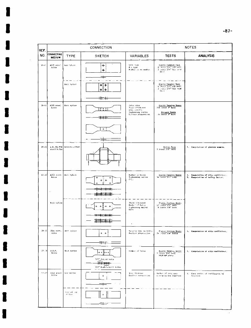
IIIIIIIIIIII
-87-
CONNECTION NOTESREF.
NO. CONNECTINGTYPE SKETCH VARIABLES TESTS ANALYSISMEDIUM
59-7 A32S steel Lap splice
1:1Holt type Static Tension Test
bolts Nut type 6 tests 3/4" rib boltWasher or no wllsher 3 tests 3/4" hex he.:ld
bolt
I- - --- ------- -- ----- - -- - -- ---Butt splice
DOStatic Tension le-st
I' 6tests3/~t:
.1:. J tests 3/4" hel( he-adbolt
=t=I=59-12 A325 steel Butt splice
C 8JOil~t size Static Tension Trsts
bolts I::::::. :::iPL,te thickrU'ss 230 tests I" boltHolt patternTightening torq,!t' Fatigw~· l'estsSurface preparation 15 tests P' bolt:
I I I
C :=J+
I59-13 B.S. No.970 beam-to.co lumn .-L Static test 1. Computation of plastic mClllle'ot.
steel bolts 2tes[~
:/ ""II I I III "~V I
59-14 A325 steel Butt splice Number of bolts Static Tension Test.s 1. CO'lI:Iputation of slip coefficient.bolts CJ: +!) + :CJ Tightening m~thod 36 tests 3/4" bolt 2. COIlIputation of safety factor.
Grip
1-----1--
IIIIIII
Butt splice
59-15 35SG steel Butt splicebolts
59-16 H.S.F. Butt spliceBoits
sq·]" A:l25 stl'P[ L"p spliceholts
J;1<,'~ 1~'d 1;1 rs:,lic"
'----__/_+_+--'---_----J
D±I:J1/2" fitted bolts
IT II'-v--'
3/1:l" High-tens Lon hoi ts
~I_+-,------I_
_1rr=J---=P~---
Plate thicknessNumber of boltsTightening methodGrip
Tensile loRd on boltsSurface preparation
Number ~f holts
IL1\t di":nl-'tp:"5nr f. <",.,. ~rC'flar[lt ion
Static Tension Tests12 tests 3/4" bolt
6 tests lIB" bolt
Static Tension Tests24 tests 7/'d" bolLs
Stat ie Tenskm Tests9 r;;rs )}~" bo-lt-
HEJO-WP plat{"
Number "f [('St cor:dUeled is n~t rep:ntpd
1. Computation of slip coefficient.
I. COIllputation of slip coefficient.
1. C~):nP'ltfltion ,,[ coefficient offriction.
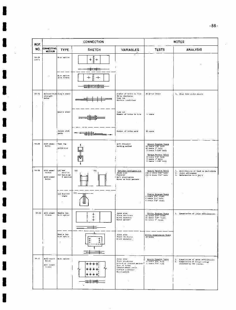
IIIIIIIIIIIIIIIIIII
-88-
CONNECTION NOTESREF.
NO. CONNECTING TYPE SKETCH VARIABLES TESTS ANALYSISMEDIUM
/'/
59-19 811tt splice D II D. con't +:1+II
"I I
f--- t---------Butt splice D I' D+ II +..... ith liners ,I
,I
--~- ---1----- ----- ---
59-25 Waisted high Single shear Number of bolts in line 36 Sl~ear Tests \, Slip loae! plate stressstrength
~Plate thickness
bolts Type nutSurface conditions
f------ ---Doub Ie shear Type nut
==P=Number of bolts in line 4 tests
f--------
Joints with
II INumber of bolts used 10 tests
packs - I -59-29 A325 steel Test jig
~Bolt diameter Direct TensIon Tests
bolts Loading method HI tests 7/6" boltCalibrator 10 tests 1" bolt
5 tests 1-1/8" bolt
Torque tension Tests6 tests 11M" bolt3 tests 1" bolt2 tests 1-1/8" bolt
59-30 A141 steel (8) box (a) (b) 5 pecimen Conf1gurat ion Static Tension Tests \, Distribution of load to pull-platerivets section
It tLJoint size (a) 4. tests 3/4" bolt 2. Joint efficiency
(b) bui It-up Fastener (b) 4 tests 7/8" bolt 3. Deformation in a jointA325 s tee 1 1 section Hole preparationbolts Rivet or Bolt pattern
f---- --------(c) Starred <o>~__ Static Tension Tests
angle 8 tests 3/4" rivet6 tests 3/4" bolt11 tests 71B" rivet
I59-32 Al4l steel Double lap I + D
Joint size Static Tension Tests 1. Computation of Joint efficiencies.rivets. butt splice I Plate thickness 33 tests 3/4" dvet
I + Rivet diameter 24 tests 7/B" rivetI + Rivet pattern 64 tests 1" rivetI
It------------- ----- ------_.-
D,:)uble lap
QJoint size Static Compression Tests
butt splice Plate· thickness 1M testsRivet diameter
I I59·]; Aj25 steel butt splice J~int size Static Tensi~n Tests I. Computati~n of joint efficiencies
b~lts Plate thickness 2 tl'sts 3/4"~ 2. Computation ~f strain energy+++t: B:llted ~r riveted pattern 4 tests 7/M" holt i!hsorbed by the joints.Al41 stcpl Type of h~les
rivets ++++: '7 Tensi()n·shcar ratio'7 Surface c::mditi~n
I Misali~nment
++++:I 1 I I
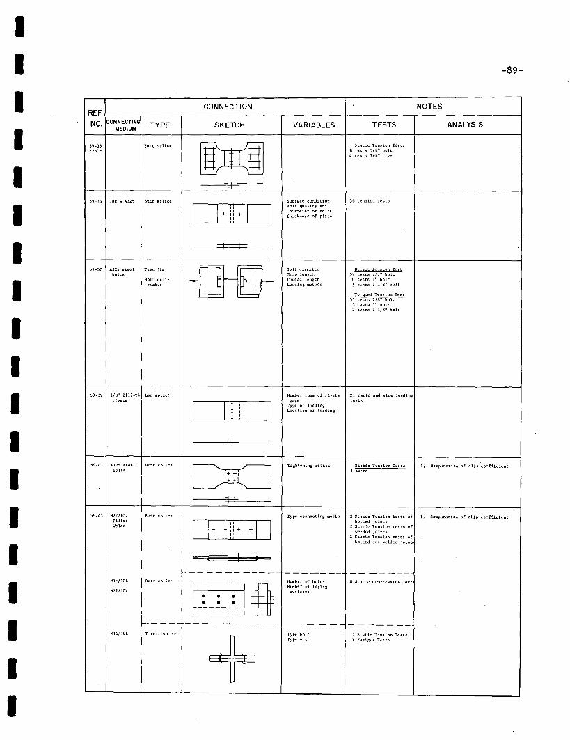
IIIIIIIIIIIIIIIIIII
-89-
CONNECTION NOTESREF.
NO. CONNECTING TYPE SKETCH VARIABLES TESTS ANALYSISMEDIUM
59-33 Butt splice
MStatic Tension Tests
con't ~ test~ 3/4" bolt4 tests 3/4" rivet
I
59-36 10k. 6< A325 Butt splice Surface condition 56 Tension Tests
D II + DBolt quality and
+ diameter of boltsThickness ~f plate
I I
59-37 A325 steel Test jig -00- Bolt diameter Direct Tension Testbolts Grip length 39 tests 7/8" bolt
Bolt cali- Thread length 10 tests 1'1 boltbrator Loading method 5 tests 1-1/8" bolt
Torqued Tension Test51 tests 7/8" bolt
3 tests 1" bolt2 tests 1-1/8" bolt
59-39 1/8" 2117-T4 Lap spliCE! Number rows of rivets 21 rapid and slow loadingrivets
I I+l I
gage tests
!Type of loadingLocation of loading
+I
59-41 A325 steel Butt splice Tightening method Static Tension Tests 1. Computation of slip coeffiCientbolts DO 2 tests
+ +'I I
59-43 H22/l0k Butt splice Type connecting media 2 Static Tension tests of 1. Computation of slip coefficientFillet
D+ Ii + + IJ bolted jointsWelds 2 Static Tension tests of
+ welded joints2 Static Tension tests of
bolted and welded joinO
I I I If--- ---- ----- ------- -- -----
MH,/lOk Butt splice Number of bolts 8 Static Compression Test
§ ftNumber of faying
M22/10k surfaces
f----- ---- ------- -- - --- -- -----Ml6/10k T s(!ctiorl butt
+Type bolt 12 Static Tension TestsType mit 8 Fatigue Tests
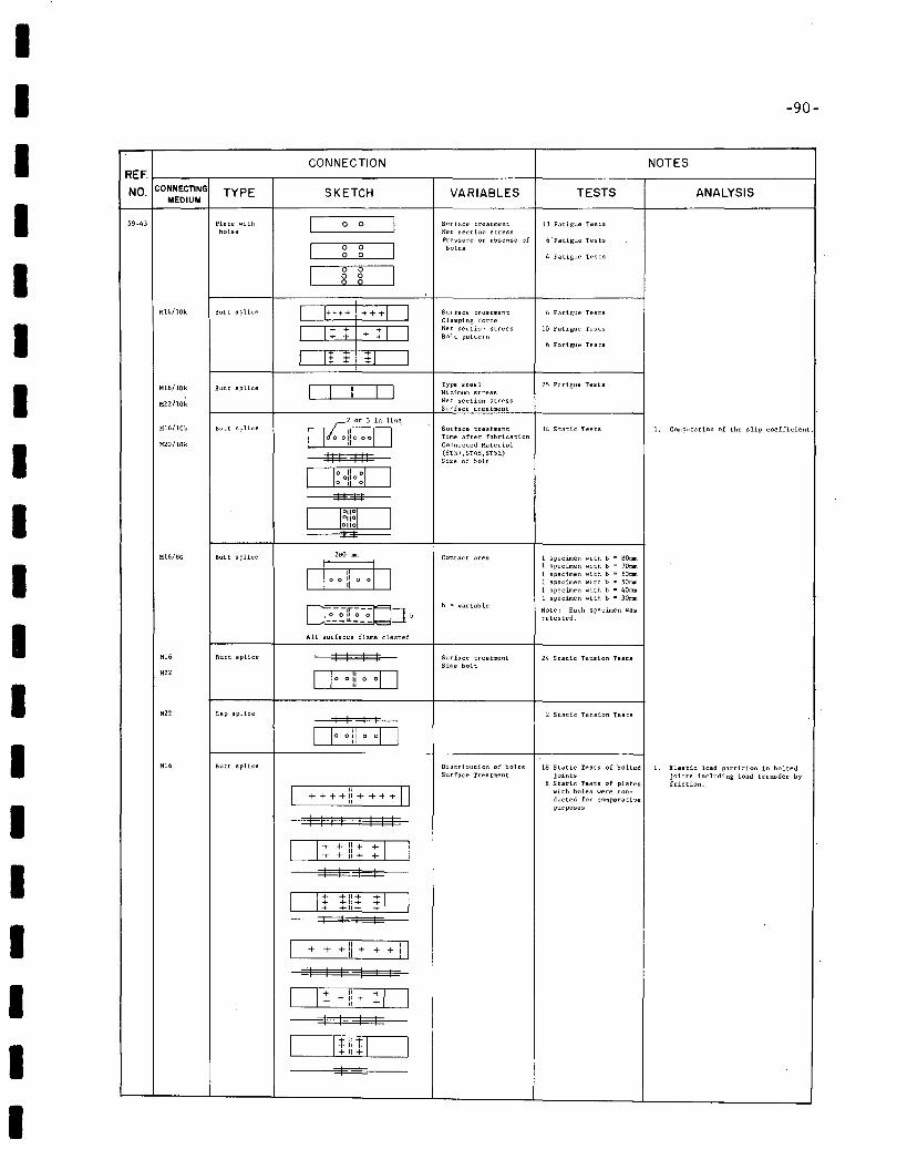
II -90-
ANALYSIS
NOTES
TESTS
6 -Fatigue Tests
4 Fatigue Tests
13 Fatigue Tests
VARIABLES
Surface treatmentNer section stressPressure or absense ofbolts
SKETCH
....1 __->8,-->8<-__1
CONNECTION
I 0 0 II g g I
Plate withholes
59-43
REF. 1-__,---__---, ----,,-- -+ ---, ---1NO. CONNECTING TYPE
MEOIUM
IIII
M16!lOk Butt splice1
I
I
I++;+! +++1
It :t' i 1
1
I
1
Surface treatmentClamping forceNet section stressBolt pattern
6 Fatigue Tests
10 Fatigue Tests
6 Fatigue Tests
II
Mi6/10k
H22!lOk
Mi6/lOk
H20/10k
Butt splice
Butt splice
I Ic2 or 3 in line,
D/O O!IOOOOII I ++t-----
038[]11, o01 °° I °
Type steel 25 Fatigue TestsMinimum stressNet section stressSurface treatment
Surface trcstment 34 Static TestsTime after fabricationConnected Material(5T37 ,5T48,5T52)Size of bolt
1. Computation of the slip coeffici~nt.
III II
2tsO mm
All surfaces flame cleaned
I I I I
1. Elastic load partition in boltedjoints including load transfer byfriction.
2 Static Tension Tests
24 Static Tension Tests
18 Static Tests of hoI tedjoints
8 Static Tests of plateswith holes were conducted for comparativepurposes
1 specimen with b = 80mm1 specimen with b = 70mm1 specimen with b D 60mm1 specimen with h .. SOmm1 specimen with h D 40Il1l\1 specimen with b a 30mm
Note; Each specimen wasretested.
b = variable
Contact area
Surface treatmentSize holt
Distribution of boltsSurface Treatment
I 1 I I
OLO_O...!!.!...!_°_°0
I I I I
" 0++++"++++"
0"o 0 Ii 0I,
+11++11++11+
I I
I I
O ,+"±:----'+--"-"-'+'----+±_D_ +11+
I + + + Ii + + + IJ
Lap splice
Butt splice
Butt splice
Butt splice
H22
H22
H16
H16
H16/BG
IIII
II
I0 ...._:-_+----'1'-:_+_-'~_D
I I I III I I I I I
I c:=rrrn=J"++11++11+
I I
I
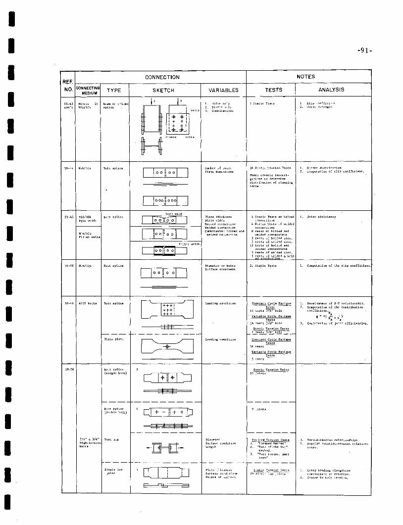
II -91-
ANALYSIS
1. Slip coefficient2. Joint strength
NOTES
TESTS
3 Static TC'sts
VARIABLES
1. Bolts only2, Rivets o;>nly3. C:lmbinations
SKETCH
CONNECTION
59-43 Rivets 25 Beam or columncon't H24/lOk splice
REF. f----..------r-----------,-------f--------r-----------iNO. CONNECTING TYPE
MEDIUM
IIIII
59-44 Mi6/1Ok Butt splice Number of bolts,Plate dimensions
10 Static Tension Tests
Photo elastic investigations to determinedistribution of clampingforce
L Strei;s distribution2. Computation of slip coefficient.
IIII
59-45 Mi6/10k Butt spliceButt 'Welds
Mi6/lOkFillet welds
M16/1O.k Butt .splice
butt weld
CE~Jr-?--i:D
fillet welds
C88=J
[]oo!!o 00
Plate thicknessPlate widthBolted connectionWelded connectionCombination bolted and
welded connection
Diameter of holesSurface treatment
4 Static Tests of boltedconnections
4 Static Tests of weldedconnections
8 tests of bolted andwelded connections
3 tests of bolted conn.7 tests of welded conn.
12 tests of bolted andwelded connections
3 tests of welded conn.5 tests of welded & bolt
21 Static Tests
1. Joint efficiency
1. Computation of the slip coefficient
1---.- ----------
1----- --------
1. Development of S-N relationship.2. Computation of the distribution
coefficient.N
Ae = f( NA
+ N/3. Computation of joint efficiencies.
Static Tension Tests10 Joints
Variable Cycle FatigueTests
5 tests
Constant Cycle FatigueTests
19 tests "'3'7B"bolt
Variable Cycle .FatigueTests
16 tests 3'7"B" bolt
Static Tension TestsI- ~e~37£...bolt__
Constant Cycle FatigueTests
3M tests
1-------
Loading condition
Loading condition
III
1
+++1+++:+++,
Butt splice
Plain plate
Butt splice(single bolt)
A325 bolts59-49
59-50
IIIII
Butt splice(double bott) LJ++ ++[) 9 joints
I7/8" & 3/4" Test jigHigh-tensionbolts
f---------
DiameterSurface conditionLen~th
1-------Torque~ Tension Tests
I. ''Torqued Method"2. ''Turl'-of-the Nllt"
method.3. "Part torque, part
tllrn"
1. Torque-tension relationshi.ps2. Angular rotation-tension relation
ships.
--- ------- ,-----1------
II
Sin~te lapjoint
Plate. t!1icknessSurfuce c:>nditionsShu pes ~)f washers
Slalic Tensior. Tests29-sin~t;;t;p"~~
1. Creep bending elongationc~)efficient of friction.
2. Change in bolt tension.
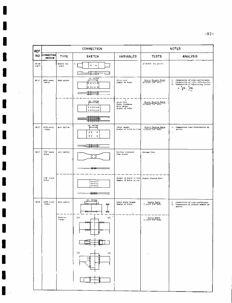
III
-92-
CONNECTION
II
59-50 Double lapcon't joint
SKETCH
'c[J++iE? 1=$
VARIABLES TESTS
17 Double ~ap joints
ANALYSIS
I60-2 A325 steel Butt splice
bolts
no. varies
ct:::iII I
Joint sizeNumber of holes
Static Tension Tests16 tests 718" bolt
1. Computation of slip coefficients.2. Co:nputation of joint efficiencies.3. 'Computation of unbuttoning factor.
R TU=~ .. !:!a
R Tult
II
1-----1------------~
D~+++HD+++ ++...
Joint sizePlate thicknessGrip lengthNumber of bolts
Static Tension'Tests16 tests 718" bolt
I60-5 A325 steel Butt splice
bolts
no. varies
r------1
D:: :1Joint length Static Tension TestsNumber of bolts in line 4 tests 7/8" bolt
1. Computation load distribution injoints.
- --,--1-----------Number of bolta in line Static Tenaion TeatNtunber' of bolta in row
III
60-7 lis" black Butt splicebolts
7/8" blackbolts
II I
CI::i :=JI I
Surface treatmentTime tea ted
Fatigue Test
----- ---
1. Computation of slip coefficient.2. ~:~~~tion of plastic moment: c~-
Static Tests2 tests 3/4" bolt
Cover plate lengthNumber of bolts
Static Tests4 tests 3/4" bolt
-----.:.. ----------
II
--
IIII
II
Beam splice
~I-----1- - ------ ---Beam-to- (a) (b) ~column -"--
A325 steelbolts
II
I
IIII
~(c) r+ (d)
I = i~':rF------j1r ~c4- l
rr::ESt=J
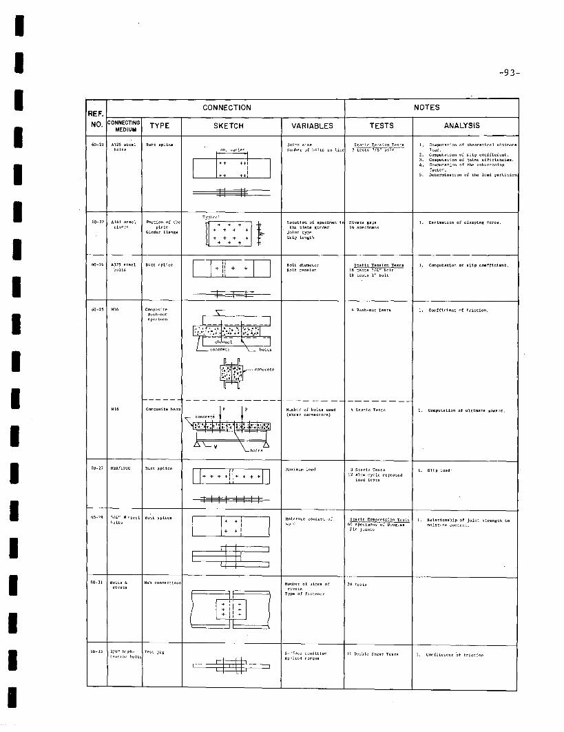
II -93-
VARIABLES TESTS
Joint size Static Tension TestsNumber of bolts in line !:I t'ests 7/8" bolt
Location of specimen i Rivets gapsthe plate girder 16 specimens
Joint typeGrip length
IIIIII
CONNECTIONREF.
NO. CONNECTING TYPE SKETCHMEDIUM
60-21 A325 steel Butt splicebolts d:: ·"'::1
++1
II II
Typical60-22 A141 steel Portion of the
~:~:~:::I~rivets plate
Girder flange
60-24 A325 steel Butt splice D !i Dbolts + + +Bolt diameterBolt tension
Static Tension Tests18 tests 3/4" boltHI tests 1" bolt
NOTES
ANALYSIS
1. Computation of theoretics 1. ultimateload.
2. Computation of slip coefficient.3. Computation of joint efficiencies.4. Computation of the unbuttoning
factor.5. Determination of the load partition
1. Estimation of clamping force.
1.. Computation of slip coefficient.
------- --------
IIIII
60-25 Mi6
MI6
60-27 H20/101C
Compositepush-outspecimen
1--- ---Composite beam
Butt .splice
I It
concrete lP lP
\ I
Number of bolts used(shear connectors)
Maximum load
4 Push-out Tests
4 Static Tests
3 Static Tests12 slow cycle repeated
load tests
1. Coefficient of friction,
1. Computation of ultimate moment,
1. Slip load"
60-29 3/4" 0 st.eel Butt splicebolts
IIII
60-31 Bolts ["rivet.s
Web connections
!
I I I I
Moisture content ofwood
Number of lines ofrivets
Type of fastener
Static Compression Test!.' I, Relationship of joint strength to60 specimens of Douglas moisture content.Fir joints
78 tests
II
00-)) 3/4" hiRh- Test jigtensi"n holts
Surface conditionApplied torque
11 DO'Jble Shear Tests 1. Coefficient 'of friction
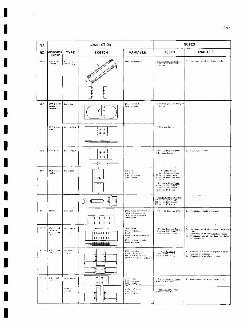
60-36 A141 steel Built-uprivets Chord LoUt
IIII
REF.
NO. CONNECTINGMEDIUM
TYPE
CONNECTION
SKETCH
\
VARIABLE
Bend parameters
TESTS
Static Tension Tests3~t;-;rend post in
truss
-94-
NOTES
ANALYSIS
1. Computation of ultimate load.
III
61-4 3/4" 6< 5/H" Test jigRuckholtfasteners
n10101
Diameter of boltType of bolt
27 Direct TensLon-FatigueTests
--- f------.--I------
III
61-5
7/8" Ruckbolt
7/8" A325
Butt splice
Butt splice
___..:-:_:----'c
=:J:: ==
3 Fatigue Tests
1 Static Tension Tests2 Fatigue Tests
1. Slip coefficient
IIIIIIIII
61-7 A325 steel Test jigs
LJbolts
n,
JP c=P ;J61-8 Rivets BOl( beam I I
I : : : : : I61-9 A141" steel Butt splice I Irivets
A325 steel
Ittttttttt:
Ibolts
tHttttt+1
III1IIII161-10 A325 steel. Beam-to-
~bolts column
0E3=J01-11 B.S. 1083 Butt s pUce 0+ :1: +0bolts
Beam-to-
~collimn
Nut sizeNut typeLoading methodLubrication
Integrally stiffened orriveted stringers
Or riveted (. bondedstringers
Joint sizePlate thicknessPitchNumber of fasteners in
lineTension-shear ratio~astener type
Bolt diameterNumber of boltsEnd plate thicknessCoillmn stiffener thicknes
J::lin t s iz~'
llol t diame~l'r
ll~) Itt e 11 ::; i :l r.Nilmher ·.)f b~l1 ts
Nllmb~'r :If hell Ls
L~'dd r<.!':":l'll:ll: ". l' '". ~ i :"~
Tensile TestsNut Striping Tests
26 tests hesvy nuts27 tests finished thick
Ultimate Load Tests10 tests 374" bolts. 6 tests 7/8" boltsIi tests I" bolts
Torqued Tension Tests216 tests 374" bolts144 tests 7/8" bolts216 tests I" bolts
3 Static Bending Tests
Static Tension Tests5 tests 7/8" bolt2 tests 7/8" rivet
Static Tests3 tests 3/4" bolt2 tests 7/8" bolt
Static Tensi:>o Tests4 tests 578" holt
1. Predicted statia strength.
1. Computation of theoretical ultimateload.
2. Computation of unbuttoning factor3. Determination of. the load partition
at ultimate.
1. Computation of load capacity of column web stiffeners.
2. Computation of plastic moment.
1. Complltation of slip coefficient.
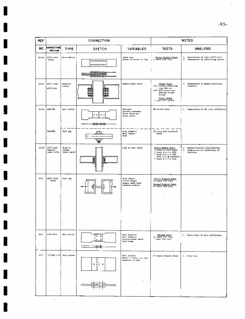
IIIIIIIIIIIIIIIIIII
-95-
REF CONNECTION NOTES
NO. CONNECTING TYPE SKETCH VARIABLES TESTS ANALYSISMEDIUM61·14 A325 steel Butt splice Joint size Static Tension Tests 1. Computation of slip coefficient.
bolts
O:::::I::::j INumber of bolts in line 4 tests 7/'0" bolt 2. Computation of unbuttoning factor.
I II I II II I I I
~,-------
61·21 A141 rivet Beam-to- Homent·shear ratio Static Tests 1. Computation of moment-reshtingcolumn
'~=
3/4" rivets connecting capacity.A325 bolt beam web and
314" A325 bolts con-necting columnflange
Static Tests1 test 3/4" rivet.s
'----
61·31 Mi6/10k Butt splice
D++!!HOMsterial 20 Static Tests 1. Ca.nputatlon of the slip coefficientSurface treatmentPlate thicknessPlate width
I I I If-- --- ----------- ---- --- ------
M16/H20 Teat jig
VBolt diameter 50 Creep and Corrosion
I IBolt length TestsTim,
i
61-36 3/4" high Sealll-to- ~ Type of sea tangle Static Moment" Teats 1. Moment·relation relationships.tensile colUllln 7 tests no seat angle 2. Computation of coefficient ofsteel bolts (seat angle) 7 tests 6 x 4 x 3/BL friction.
7 tests 6 x 4 x 3/BL
I Jl Wwith 1/4" t stiffener
7 tests 6 x 4 x 3/4L
~
62-2 A325 steel Test jig Grip length Direct Tension Testsbolts
-£]=fiThread length 32 tests 7/8" boltLength under head
Torqued Tension TestsLosding conditon24 testa 718" bolt
62-3 A325 bolt Sutt splice c:rr=J Hole diameter Fatigue Tests 1. Co:nputation of slip coefficient.Bolt diameter 11 tests 3/4" bolt
,+ + Tension-shear ratio 1 t"est 5/8" boltLoad range
I I
62-5 3/4''UNC x 4" Butt splice Bolt pattern 17 Static Tension Teats 1. Slip load
II thunber of bolts in lineDiameter of holeII
+ 11++II
, m ,
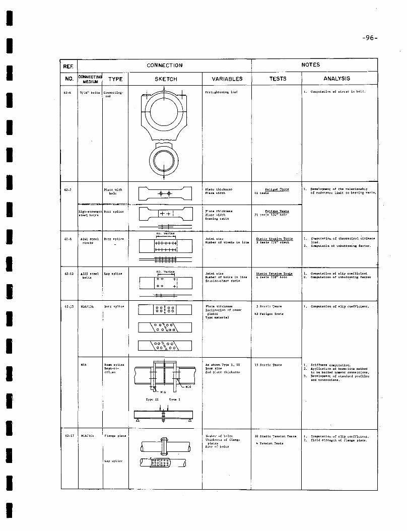
IIIIIIIIIIIIIIIIIII
-96-
REF. CONNECTION NOTES
NO. CONNECTING TYPE SKETCH VARIABLES TESTS ANALYSISMEDIUM
62-6 9/16" bolts Connectlng- ---l-.. I pcetightening load l. Computation of stress in bolt.
,od
©62-7 Plate with [ J Plate thickness Fatigue Tests l. Developnent of the relationship
hole ++ Plate width 41 teats of endurance limit to bearing ratio.
e ~High-strength Butt splice 1++ I Plate thickness
71 tes~:t~14~ ~~~~ssteel bolts 1 Plate widthBearing ratio
--- I Ino. varies
62·8 A141 steel Butt splice ~ Joint size Static Tension Tests l. Computation of theoretical ultimaterivets - D::: ~ : ::1 I
Number of rivets in line 3 tests 718" rivet load.2. Computat~n of unbuttoning factor.
III I I ":
I I1III1
62-U ll2.S steel Lap spliceno. varies
Joint size Static Tension Tes,$a l. Computation of slip coefficient~
bolts 0:: +1
INumber of bolts in line 4 tests 718" bolt 2. Computation of unbutt~ning fac~or
1Tension·shesr ratio
+1
, I I. I
62-.15 M16/l0k Butt splice 0° 011 °°0 Plate thickness 5 Static Testa 1. Computation of slip coef"ficient.Inclination of covero 0 ~l 00
platea 43 Fatigue TestsType material
I \00\00i\ I°0\\0°I ';0\\00\ I00'\00
Mi. Beam splice
UAs shown Type I, II 15 Static Tests l. Stiffness computation.
Beam-to- e Beam size 2: Application of beam-line methodcolumn End plate thickness to"be bolted moment connections.
3. Development of standard profilesand connections.
I\-: Mi.
Type 11 Type 1
I1,1
A I2i
62-17 M16/l0k Flange plate Number of bolts 10 Static Tension Tests l. computation of slip coefficient.
c1IThickness of flange 2. Yield strength of flange plate.
Dplates 4 Tension Tests
Size of bolts
Lap splice p )g00\000) 6og)02'6
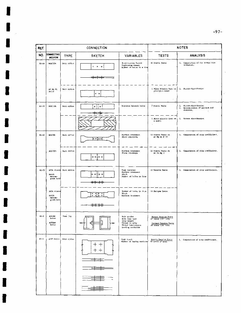
IIIIIIIIIIIIIIIIIII
-97-
REF. CONNECTION NOTES
NO. CONNECTING TYPE SKETCH VARIABLES TESTS ANALYSISMEDIUM
62-18 M16/10k Butt splice Prestressing forces 10 Static Tests 1. Computation of the stress dis-
0+ + +( I Tightening moment tribution.Number of bolts in a lin
I I I
--- - - - - - - - -- 1--- ---- - ---- -Ai Kg 51 Butt splice 1 Photo Elastic Test on 1. S tres 8 -dis t ribution
Bolts
I \+ +1 Iplexiglas model
62·19 H16/10k Butt splice Distance between bolts 7 Static Tests 1. Stress -distribution2. Determination of minimum end
distance,
I If-- -- - - -- - - f-- - - --- --- - --
~1 Photo Blastic Test on 1. Stress distribution
8 model
62-22 MIO/8G Butt splice Surface treatment 33 Static Tests on 1. Computation of sUp coefficient,
C F+HHI =J Plate thickness Ai Kg 51 F 32
----- - -- - ---- - - -- - - -- -----:--M16/10k Butt splice Surface treatment 15 Static Tests on 1. Computation of slip coefficient.
0++11++0Plate thickne.ss AlCuKg2
62·25 SV34 rivet Butt splice Trpe fastener 12 Tensile tests 1. Computation of '-lip coefficient.
0+1;++0 Surface treatment81154 Pitch
medium- Number of bolts in linegrade bol
I I I I---- ---------- - ----- -------
SV34 rivet D: :0Number of bolts in line 12 Fatigue Tests
:1 I: Pitch81154 Surface treatment
medium.grade bol
I I I I
63-2 A354BC Test jig
--[H}Bolt grades Direct Tension Tests
bolts Bolt head type 27 tests 7/8 11 bolt
A354BDGrip lengthThread in grip Torqued Tension Tests
bofts Thread lubrication 56 tests 7/8" boltLoading condition
63-3 A325 bolts Butt splice ~ Type steel Static Tension Tests 1. Computation of slip coefficient.I Number of faying surface 18 tests 1" boltI + +II + +II
'-----' '----
I I
I I
===asq§§
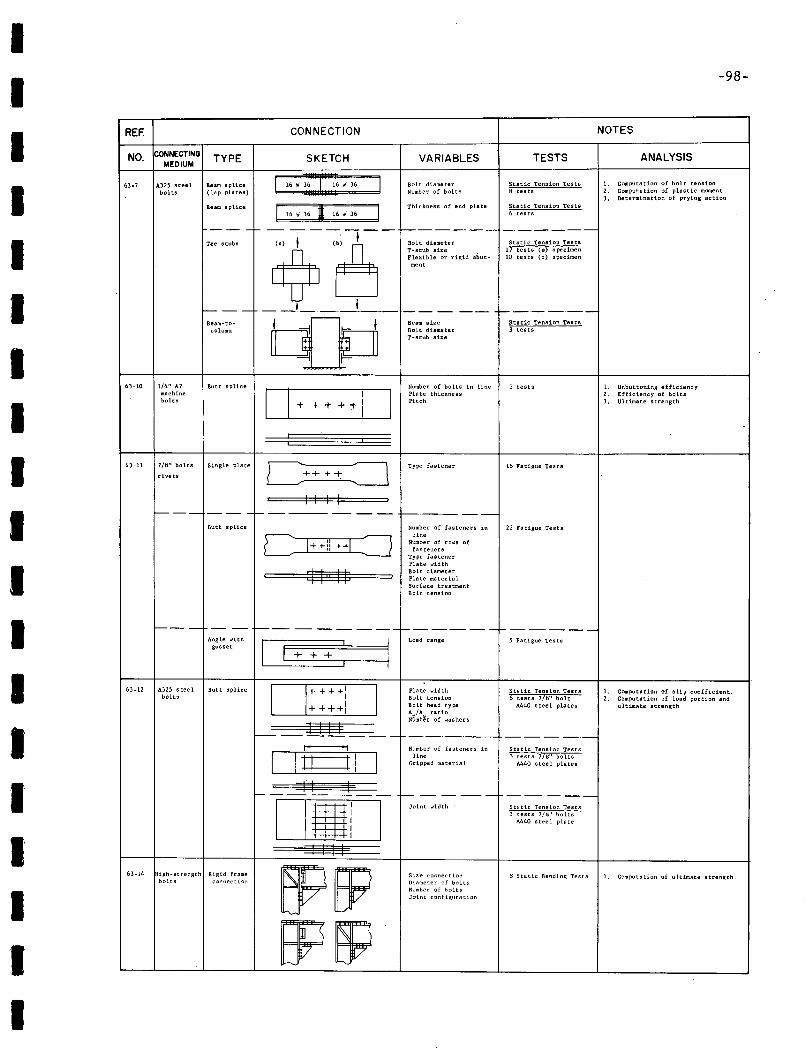
II
-98-
------------
~_._--_.-
IIIIII
REF.
NO.
63-7
63-10
CONNECTINGMEDIUM
A,325 steeLboLts
1/4" A7machinebolts
TYPE
Beam splice(lap plates)
Beam splice
---Tee stubs
f----Beam-ta
eolumn
Butt splice
CONNECTION
SKETCH
116W~W36 II 16 W 36 I 16 'N" 36 ,
-:;-, - <~-
_~__l __
O I I++++t-l,------,----I
VARIABLES
Bolt diameterNumber of bolts
Thickness of end pIa te
Bolt diameterI-stub sizeFlexible or rigid abutment
Beam sizeBoLt diameterI-stub size
Number of bolts in linePlate thicknessPitch
TESTS
Static Tension Testsl:l tests
Static Tension Tests6 tests
Static tension Tests17 tests (8) specimen10 tests (b) specimen
Static Tension Tests3 tests
] tests
NOTES
ANALYSIS
1. Computation of bolt tension2. Comput:ation of pLastic moment3. Determination of prying sction
1. Unbuttoning efficiency2. Efficiency of bolts3. Ultimate strength
I 63-11 7/tf." bolts Single plate
rivets
Type fastener ltf.-Fatigue Tests
f-- - - - - -f- _.- ----- -- -- t---.--- ---
II
Butt splice
I I I I
==$$Sl$ .
Number of fasteners inline
Number of rowS offasteners
Type fastenerPlate ....idthBolt diameterPlate materialSurface treatmentBolt tension
22 Fatigue Tests
1---- - --1=--.-. ---~---f-------'-~-----
63-12 A325 steel Butt splicebolts
1. Computation of sUp coefficient.2. Computation of load portion. and
ultimate strength
1. Computation of ultimate strength.~ Static Bending Tests
5 Fatigue Tests
Static Tension Tests] tests 71tf." bolts
A440 steel plates
Static Tension Tests) tests 7/ij" bolts
A440 stee 1 plate
Static Tension Tests6 tests 7/tf." bolt
A440 steel plates
------Joint width
Number of fasteners inline
Gripped materia I
_._-_._.- ------
Size cor-nectionDiameter of boltsNumber of b~lts
Joint configllrlltion
Load range
Plate widthBolt tensionBolt head typeAn/As ratio .Number of washers
r------
I I
DBi II I I I
O..=::II::::::::::!:JI1'-.-'II I
D ++++: I++++i----'-----
1---....:'===++===+:::r---:---jl
-
Rigid framec~n:Jectlon
Angle withgusset
igh_strengthbolts
63-14
'I
II
II
II
I
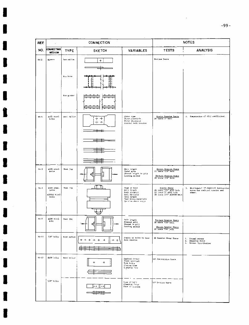
IIIIIIIIIIIIIII
III
-99-
REF. CONNECTION NOTES
NO. CONNECTING TYPE SKETCH VARIABLES TESTS ANALYSISMEDIUM
I64'-2 Rivets Lap splice I
+ CJ Fstigue TestsII
IBox beam r-t~I
P I II IU I II III I Ii ih I
Box girder
00[ ~o
Static Tension Tes"ts 1. Computstion of slip coefficient.64-4 A3Z5 steel Butt splice I +Joint type
bolts I Plate materials 29 tests 1" bolt
I + Pia te thickness
I Initial bolt tension
I I
1 1
::g
~64-5 A490 steel Test jig -fIHJJ- Bolt length Direct Tension Tests
bolts Totsl grip 21 tests 7/tJ" boltThread length in gripLoading method Torqued Tension Tests
26 tests 7/M" bolt
64-6 A325 steel Test jig fTT1 Type of bolt Static Tests 1. Development of empiresl interactionbolts
IBolt length t:I6 tests 374" A325 bolt curve for combined tension andBolt diameter 10 tests "I" A325 bolt shear.
A354BD steel Bolt hardness 20 tests 3/4" A354BD boltbolts Grip length
Test block materials
ITension-shear ratio
~64-7 A490 steel Test jig -fIHJJ- Bolt length
bolt Torqued Tendon TestsNominal grip 20 tests 7/8" boltThread in gripLoading method Direct Tension Tests
20 tests 7/8" ,bolt
64-11 7/8" bolts
1+Butt splice
Ii +\ Number of bolts in line 10 Tension Shear Tests 1, Normal stress+ + + ++ + Bolt tension 2. Shearing force3, Stress distribution
~I I I I~64-12 SA90 bolts Butt splice
[IApplied torque
il324 Compression Tests
+ + Plate materialType boltsTesting timeClamping time
~f----f----- ____ ---------------
5/8" boltsType of holt 322 Tension Tests
I 1++ 1:++1 IClamping forceTime of testing
~
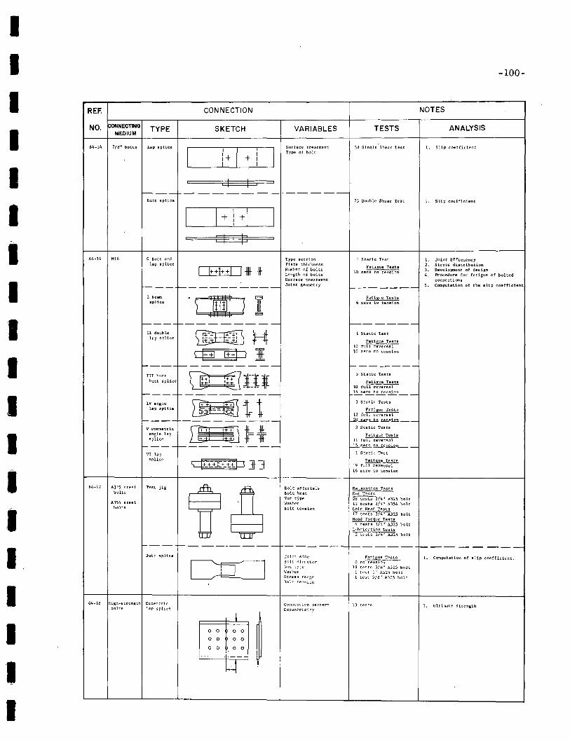
IIIIIIIIIIIIIII.IIII
-100-
REF. CONNECTION NOTES
NO. ~ONNECTING TYPE SKETCH VARIABLES TESTS ANALYSISMEDIUM
64-14 7/8" bolts Lap splice Surface treatment 38 Slngle Shear Test l. Slip coefficient
II
I,
IType of bolt
1+ I+ II I
I 1,,
f----.- -- -- -- ---- -_.- -----Butt splice 23 Double Shear Test l. Slip coefficient
I II
+I~+ II,
N9J ,
64~16 M16 o Butt snd Type section 1 Static Test 1. Joint Efficiencylap splice Plate thickness
Fatigue Tests 2. Stress distribution
1 I++!++I l-llt *Number of bolts 3. Development of designLength of bolts 10 zero to tensi::m
4. Procedure for fatigue of boltedSurface treatment connections
--- f----------- Joint geometry~------
5. Computation of the slip coefficient
I beam :m: } IFatigue Tests
splice ) 6 zero to tension
1------1---------- f-------.-II double ffiFffill H 1 Static Test
lap splice L=t:- - -.;J Fatigue Teats10 full reversal
qHJ $P I 10 zero to tension
'----1---------- '-------III butt lJI' ;[Illl 3 Static Tests
butt splice Fatigue Tests++110 full reversal
1----1--------- ~e~t~n!2:2..n__
IV angle
~ 1r t 3 Static Tests
lap splice Fatigue Tests~ 12 full reversal
f---- --------- l-iP-=-o....t..o.=1oIl.__V symmetric W! 'ED wt 3 Static Tests
angle lap Fatigue Testssplice I -+ 11 full reversal
~---t----------- ~z.,U.Q...t.2..te.D.l12TL..--
VI lap 1 Static Test
splice G++ +][+ ++p ]-]fFatigue Tests
19 full reversal16 zero to tension
64-17 A325 steel Test jig
tr~Bolt materials Relaxation Tests
bolts Bolt head Nut TestsNut type ~3/4" A325 bolt
A354 steel Washer 11 tests 3/4" A354 boltbolts Bolt tension Bolt Head Tests
12 tests 3/4" A325 boltHead Torgue Tests
4 tests 3/4" A325 boltLubrication Tests
2 tests 3/4" A325 bolt
1--- 1------------- ------ ------- 1---------Butt splice Joint size Fatigue Tests 1. ComputatiOn of slip coefficient.
CLCJBolt diameter o to tensionNllt type 19 tests 3/4" A325 boltW<lsher 1 test 1" A325 boltStress range 1 test 5/8" A325 boltBolt tension
64-18 High-strength Eccentric Connection pattern 13 tests 1. Ultimate strengthbolts lap splice Eccen~rici~,!
~ I0 o +0 0
~0 0 t 0 0
0 0 0 0
-----t----kf t
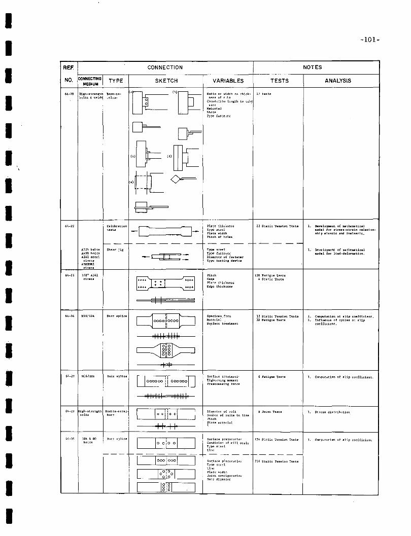
IIIII
IIIIIIIIIIIII
-101-
REF. CONNECTION NOTES
NO. CONNECTING TYPE SKETCH VARIABLES TESTS ANALYSISMEDIUM
64-20 High~lltrengt Beam-to- 'OC "'[]L Ratio of width t.o thick- 27 testsbolts £. weld column ness of tube
Connection length to tub!!size
MaterialShapeType fastener
~ [F
{}= '.[D[f~[ ()===
gs64-22 Calibration -c =:J-
Plate thickness 22 Static Tension Tests I. Developnent of mathematicaltests Type steel model for strells-strain relation-
Plate width ship elastic and inelsat1c.,Pitch of holes
f-- --1---- -- -- -- -- -- - 1--- -- --A325 bolts Shear jig Type steel I. Development of mathematicalA490 bolts
-~=Type fastener model for load-deformation.
A141 steel Diameter of fastenerrivets Type testing device
A''O!Cll2:rivets
64-25 7/8" A141 Pitch 120 Fatigue Testarivets ++++
1:+t•• Gage 4 Static Tests
+ I Plate thickness
... -++++
H'H Edge thickness
I I
64-26 M16/lOk Butt splice C:}oooliooooP Specimen. form 12 Static Tension Tests I. Computation of slip coefficient.Material 30 Fatigue Testa '. Influence of cycles on slipSu.rface treatment coefficient.
1111 1I1I
~811 80110
I I64-27 M16/l0k Butt splice Surface treatment· 6 Fatigue TestsOoooooo!! 0000000
I. Computation of slip coefficient.Tightening momentPrestressing force
III1I1 III111
64-29 igh-strength Double-strap CIHI!++O Diameter of bolt 8 Joint Tests I. Stress distributionbolts butt Number of bolts in line
Pitch
I I I Iilate material
64-35 10k & 8G Butt splice DooiooO Surface preparation 156 Static Tension Tests I. Computation of slip coefficientbolts Condition of mill scale
Type steelTime
--- -------- -- --- - r------c=J ooo! oooC] Sur.face preparation 216 Static Tension TestsType steelTime
~Plate width
00·00 Joint configurationBolt diameter
I LmJ Igig
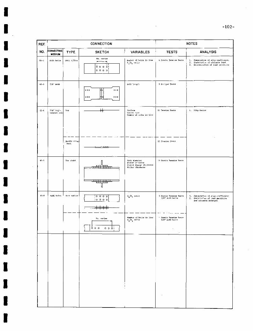
IIIIIIIIIIIIIIIIIII
-102-
REF. CONNECTION NOTES
NO. CONNECTING TYPE SKETCH VARIABLES TESTS ANALYSISMEDIUM
No. varies4 Static Tension Tests Computation of slip coefficient65·1 A325 bolts Butt splice om Number of bolts in line L
A IA ratio 2. Computation of ultimate loadn ,
3. Determination of load partition
~
65-3 7/8" A490 Bolt "length 9 Fatigue Tests~ ~
+++
m+t+
+++ +++~ ~
65-4 7/8" high- lap II Surface 26 Tension Tests L Slip factortension bol Washer type
Number of bolts in line
f---- - - ----- - --- --- -- - ---Double stra 13 Tension Tests
• butt
65-5 Tee stubs
n-rLBolt diameter 10 Static Tension TestsNumber of boltsT-stub flange thicknessFiller thickness
~
65-8 A490 bolts Butt splice
? i~0 0
~DA IA ratio 4 Static Tension Tests L Computation of slip coefficientu ,
7/8" A490 bolts 2. Computstion of load partition0 0 snd ultimate strength
I I I I---- - --------- ------ -----
No. variesNumber of bolts in line 4 Static Tension TestsA/As ratio 7/8" A490 bolts
ufo b0 0 0

III 6. AUTHOR. INDEX
IIIIIIII'I
IIIIIII
Bada1iance, R., 65-13Badir, M" 47-6Bailey, J~ C., 51-9, 52-7Baker, A.R., 61-11Ball, Eo Yo, 60-15 i 61-19, 61-24, 61-29Bangay, A. J., 59-8Baron, F., 52-5, 52-23, 53-9, 53-10,53-15, 54-1, 54-19, 55-2, 55-17
Baumgartner, T. C., 58-5Beam, W. So, 54-17, 55-11Beane, S. T.~ 58-2, 59-33, 59-59, 61-23Becker, W. K., 51-3Beede, M. C., 44-9Beedle, 1. S., 63-1, 63-12,63-15, 64-21,64-24, .65-9, 65~i3, 68-18
Bee1ick, K. H., 64-50Beer, N., 60~27, 64-27Belford, B., 60-11Belford, Ro B., 59-35, 62-13Bell, M. N., 55-41, 57-27Bell, W. G., 57-37, 58-29, 59-55, 61-21Bendigo, R. A., 59-29,59-37, 60-2, 62-12Berg, So, 55-27Bergendoff, R. C.,. 53-5, 53-17Berridge, P. S. A., 59-21,60-33Boiten, R. G., 47-3Boomsma, M., 53-35Batt, B. A., 65-13Bouwan, L. P., 54-36, 60-19Brace, A. W.,52-7Brady, W. C., 53-18, 55-12Brennecke, 43-4.Brody, I. H., 59-24Browri;A. A., 52-11
. Brown, W. C., 59-25Bruckner, W. H., 44-9Brueggeman, W. C., 36-1, 40-4, 42-1Budiansky, B., 61-2Butz, G. A., 64-45Cannon, Jo C., 59-17, 60-8Carpentier, L., 64-31Carter, J. W., 50~11, 51-14, 52-19,54-21,
54-23, 55-1, 55-19Cayci; M. A., 49-5, 50-20, 52-10Ceradine, G., 49-3Chapin, C. H., 35-2
-103-
Chauner, R. W" 57-17Chang, F, K., 52-24, 53-11Chang, W. N., 63-3, 63-8', 65-17Charlton; T. M., 60-3Chesson,E. Jr., 56-18, 56-19, 57-1,
57-33, 58-12, 58-29, 59-1,59-3,59-30, 59-38, 59-41, 59-52, 59-55,59-56,60"';4,61-7,61-17,61-20,61-21, 62-3, 63-16, 63-17, 63~18,
64-5, 64-6, 64-8, 64-13, 64-17,64~19, 64-25, 65-2, 65-3, 65-6,65-15, 65-19, 65-20, 65-25
Chiang, K. C., 64-4 .Chin, Ao G., 54-20, 55-18Christopher, R. J., 63-2, 64-21,
65-7Chronis, N. P., 60-30Chu, K., 50-19,Chu, T. V., 62-7Cioth, N~ So, 61-6Clark, J. W., 64-43Cod, J., 64,..1Committee on Design in Lightweight'Structur~l Alloys, J. W. Clark,Chairman, 56-2, 56-3
Corrado, J. A., 65-13Cowen, E. Y., 58-5Cox, N. L., 50-7, 52-25, 52-26, 56-~2
. Cox, J. W., 52-18, 53-14Cre~sy,L. R., 59-19Crispell, C., 58-5Crocker, S., 45-6Cullimore, M. S. G., 59-16, 63-6,
64-9Dassen, J. R., 63-9, 63-13, 64-15Davey, J. S., 52-8DeBack, J., 59-36, 60-19Delaney, T. J., 51-10, 54-8.Dem~l, L., 55-33, 57-32, 64-35Deming, G. M., 23-1Denkhaus, No G., 61-3Deutscher Normenanschuss, 60-39Deutscher Stah1bau-Ver1and, 57-34Dewalt, W. J., 61-33Diemer, C. P., 61-12, 62-14Dineen, R. 'L., 61-7
" ..
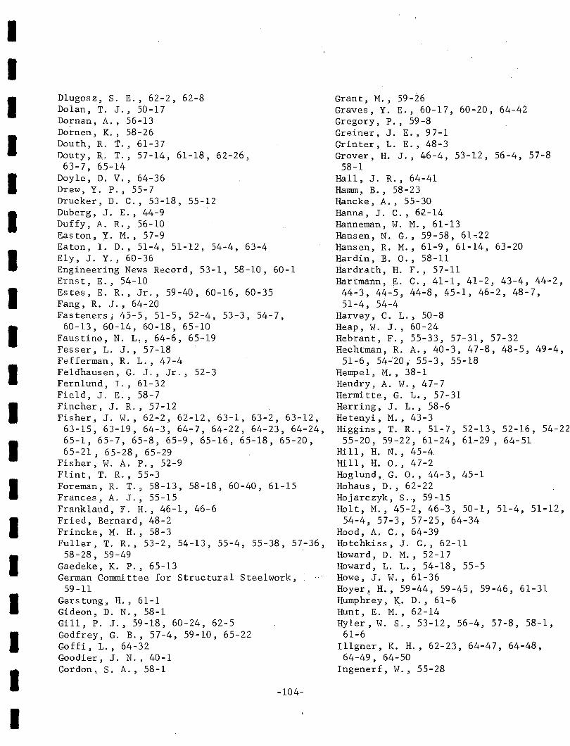
IIIIIIIIIIIIIIIIIII
Dlugosz, S. E., 62-2, 62-8Dolan, T. J., 50-17Dornan, A., 56-13Dornen, K., 58-26Douth, R. T., 61-37Douty, R. T., 57-14, 61-18, 62-26,63-7, 65-14
Doyle, D. V., 64-36Drew, Y. P., 55-7Drucker, D. C., 53-18, 55-12Duberg, J. E., 44-9Duffy, A. R., 56-10Easton, Y. M., 57-9Eaton, 1. D., 51-4, 51-12, 54-4, 63-4Ely, J. Y., 60-36Engineering News Record, 53-1, 58-10, 60-1Erns t, E., 54-10Estes, E. R., Jr., 59-40, 60-16, 60-35Fang, R. J., 64-20Fasteners; 45-5, 51-5, 52-4, 53-3, 54-7,
60-13, 60-14, 60-18, 65-10Faustino, N. L" 64-6, 65-19Fesser, L. J., 57-18Fefferman, R. L., 47-4Fe1dhausen, G. J., Jr., 52-3Fern1und, I., 61-32Field, J. E., 58-7Fipcher, J. R., 57-12Fisher, J. W., 62-2, 62-12, 63-1, 63-2, 63-12,
63-15, 63-19, 64-3, 64-7, 64-22, 64-23, 64-24,65-1, 65-7, 65-8, 65-9, 65-16, 65-18, 65-20,65-21, 65-28, 65-29
Fisher, W. A. P., 52-9Flint, T. R., 55-3Foreman, R. T., 58-13, 58-18, 60-40, 61-15Frances, A. J., 55-15Frankland, F. H., 46-1, 46-6Fried, Bernard, 48-2Frincke, M. H., 58-3Fuller, T. R., 53-2, 54-13, 55-4, 55-38, 57-36,
58-28, 59-49Gaedeke, K. P., 65-13German Committee for Structural Steelwork,
59-11Gers tung , H., 61-1Gideon, D. N., 58-1Gill, P. J., 59-18, 60-24, 62-5Godfrey, G. B., 57-4, 59-10, 65-22Goffi, L., 64-32Goodier, J. N., 40-1Gordon, S. A., 58-1
-104-
Grant, M., 59-26Graves, Y. E., 60-17, 60-20, 64-42Gregory, P., 59-8Greiner, J. E., 97-1Grinter, L. E. ,48-3Grover, H. J., 46-4, 53-12, 56-4, 57-8
58-1Hall, J. R., 64-41Hamm, B., 58-23Hancke, A., 55-30Hanna, J. C., 62-14Hanneman, W. M., 61-13Hansen, N. G., 59-58, 61~22
Hansen, R. M., 61-9,61-14, 63-20Hardin, B. 0., 58-11Hardrath, H. F., 57-11Hartmann, E. C., 41-1, 41-2, 43-4, 44-2,
44-3, 44-5, 44-8, 45-1, 46-2, 48-7,51-4, 54-4
Harvey, C. L., 50-8Heap, W. J., 60-24Hebrant, F., 55-33, 57-31, 57-32Hechtman, R. A., 40-3, 47-8, 48-5, 49-4,
51-6, 54~20i 55-3, 55-18Hempel, M., 38-1Hendry, A. W., 47-7Hermitte, G. L., 57-31Herring, J. L., 58-6Hetenyi, M., 43-3Higgins, T. R., 51-7, 52-13, 52-16, 54-22
55-20, 59-22, 61-24, 6L-29 , 64-51Hill, H. N., 45-~
Hill, H. 0., 47-2Hoglund, G. 0., 44-3, 45-1Hohaus, D., 62-22Hojarczyk, S., 59-15Holt, M., 45-2, 46-3, 50-1, 51-4, 51-12,
54-4, 57-3, 57-25, 64-34Hood, A. C., 64-39Hotchkiss, J. G., 62-11Howard, D. M., 52-17Howard, L. L., 54-18, 55-5Howe, J. W., 61-36Hoyer, H., 59-44, 59-45, 59-46, 61-31Humphrey, K. D., 61-6Hunt, E. M., 62-14Hyler, W. S., 53-12, 56-4, 57-8, 58-1,
61-6Illgner, K. H., 62-23, 64-47, 64-48,
64-49, 64-50Ingenerf, W., 55-28
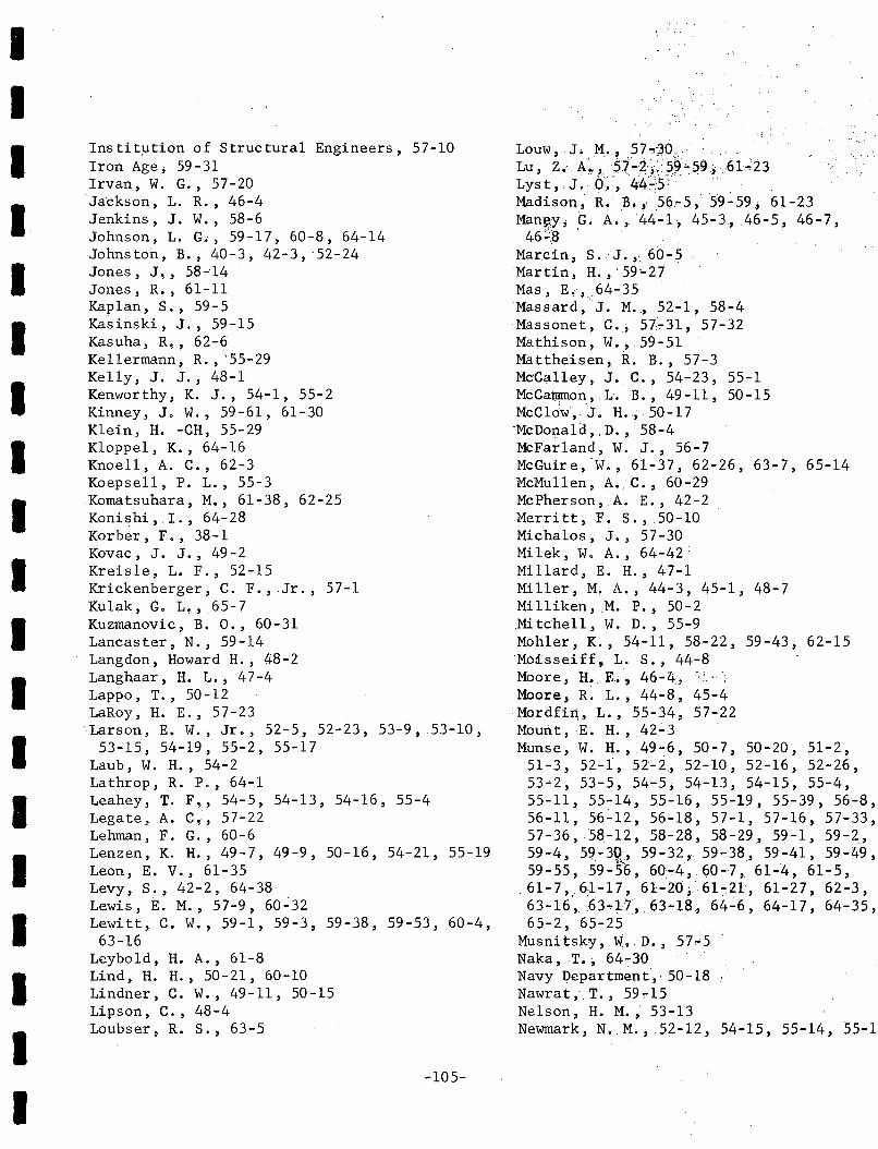
IIIIIIIIIIIIIIIIIII
Instit~tion of Structural Engineers, 57-10Iron Age; 59-31Irvan, W.G., 57-20Jackson, L. R., 46-4Jenkins, J. W., 58-6Johnson, L. G., 59-17,60-8,64-14·Johns ton, B., 40-3, 42-3,' 52-24Jones, J" 58-14Jones, R;, 61-11Kaplan, S., 59-5Kasinski, J., 59-15Kasuha, R" 62-6Kellermann, R., '55-29Kelly, J. J., 48-1Kenworthy, K. J., 54-1, 55-2Kinney, J. W., 59-61, 61-30Klein, H. -CH, 55-29K1oppe1, K., 64-16Knoell, A. C., 62-3Koepsell, P. L., 55-3Komatsuhara, M., 61-38, 62-25Konishi, I., 64-28Korber, F., 38-1Kovac, J. J., 49-2Kreis1e, L. F., 52-15Krickenberger, C. F., Jr., 57-1Kulak, G. L., 65-7Kuzmanovic, B. 0., 60-31Lancaster, N., 59-14Langdon, Howard H., 48-2Langhaar, H. L., 47-4Lappo, T., 50-12LaRoy, H. E., 57-23Larson, E. W., Jr., 52-5, 52-23, 53-9, 53-10,
53-15, 54-19, 55-2, 55-17Laub, W. H., 54-2Lathrop, R. P., 64-1Leahey, T. F" 54-5, 54-13, 54-16, 55-4Legate, A.C" 57-22Lehman, F. G., 60-6Lenzen, K. H., 49-7, 49-9, 50-16, 54-21, 55-19Leon, E. V., 61-35Levy, S., 42-2, 64-38Lewis, E. M., 57-9, 60-32Lewitt, C. W., 59-1, 59-3, 59-38, 59-53, 60-4,
63-16Leybo1d, H. A., 61-8Lind, H. H., 50-21, 60-10Lindner, C. W., 49-11, 50-15Lipson, C., 48-4Loubser, R. S., 63-5
":105-
.Louw, J. M..~ 57.,,;30, ..····Lu, z. A'.. " ·5f"'4i:.5~'".59,61;23Lys t, J. 6'~,44~'5': .... 'Madison, R~ B.". .56.... 5, 59-59, 61-23Man~y, G; A., 44':'1, 45-3, 46-5, 46-7,46~.~ ,
Marcin,. S,J. ,.,60-5Martin, H., '59"'27Mas, E".64-35Massard ,J. M" 52-1, 58-4Massonet, C,., 57... 31, 57-32Mathison, W., 59-51Mattheisen, R. B., 57-3McCalley, J. C., 54-23, 55-1McCat1l!ffion, L. B., 49-11, 50-15McC1ow"J. H.;, 50-17'McDonald, .D., 58-4MCFarland, W.J., 56-7McGuire,W., 61-37, 62-26, 63-7, 65-14McMullen, A;. C. ,60-29McPherson, A.E., 42-2Merritt, F. S., 50-10Michalos, J., 57-30Mi1ek, W. A., 64-42;Millard, E. H., 47-1Miller, M. A., 44-3, 45-1, 48-7Milliken, ,M. P., 50-2Mitchell, W. D., 55-9Mohler, K., 54-11, 58-22, 59-43, 62-15Mo:Lsseiff, L. S. ,44-8Moore, n.R;, 46-4""Moore, R~ L., 44-8, 45-4Mordfi~, L., 55-34, 57-22Mourit,E. H., 42-3Munse, W. H.,.49-:6, 50-7, 50-20, 51-2,
51-3, 52-f, 52';'2, 52-10, 52-16, 52-26,53-2, 53 ...5, 54-5, 54-13, 54-15, 55-4,55-11, 55~14~ 55~16, 55-19, 55-39, 56-8,56-11, 56~12, 56-18, 57-1, 57-16, 57-33,57-36,58-12, 58-28, 58-29, 59-1, 59 ... 2,59-4, 59-3R,59-32,59-38, 59-41, 59-49,59-55, .59-56, 60 ...4,60-], 61-4, ,61-5,
,61-7,,61..;17, 61-20;' 61-21, 61-27, 62-3,63-16~~3...L1,63 ... ia, 64"'6, 64-17, 64-35,65-2, 65-25 .
Musnitsky,W., D." 57~5
Naka, .T.; 64-:30Navy Department"50-18Nawrat, T., 59 ... 15Nelson, H. M.; 53 ... 13Newmark, N. M., 52-12, 54-15, 55-14, 55-1~
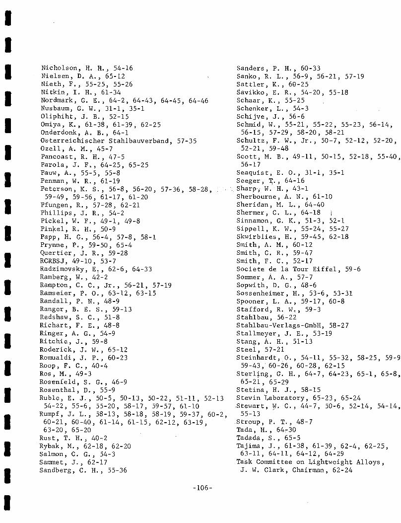
I,
52-155-2762-18
IIIIIIIIIIIIIIIIIII
Nicholson, Ho H.~ 54-16Nielsen, D. A., 65-12Nieth, F., 55-25, 55-26Nitkin, T. H., 61-34Nordmark, G. E., 64-2, 64-43, 64-45, 64-46Nusbaum, Go W., 31-1, 35-101iphiht, J. B., 52-15Omiya, K., 61-38, 61-39, 62-25Onderdonk, A. B., 64-1Os'terreichischer Stah1bauverband, 57-35Oze11, A. M., 45-7Pancoast, R. H., 47~5
Paro1a, J. F., 64-25, 65-25Pauw, A., 55-5, 55-8Penman, W. R., 61-19Peterson, K. s., 56-8, 56-20, 57-36, 58-28,
59-49, 59-56, 61-17, 61-20Pfungen, R., 57-28, 62-21Phillips, J. R., 54-2Pickel, W. F., 49-1, 49-8Pin~e1,iRo H., 50-9Papp, H. G., 56-4, 57-8, 58-1Prynne, P., 59-50, 65-4Quertier, J. R., 59-28RCRBSJ, 49-10, 53-7Radzimovsky, E~, 62-6, 64-33Ramberg, W., 42-2Ramp ton , C. C., Jr., 56-21, 57-19Ramseier, P. 0., 63-12, 63~15
Randall, P. N., 48-9Ranger, B. E. S., 59-13Redshaw, S. C., 51-8Richart, F. E., 48-8Ringer, A. G., 54-9Ritchie, J., 59-8Roderick, J. W., 65-12Romua1di, J. P., 60-23Roop, F. C., 40-4Ros, M., 49-3Rosenfeld, S. G., 46-9Rosenthal, D., 55-9Rub1e, E. J., 50 - 5, 50 -13, 50 - 22, 51-11, 52-13
54-22, 55-6, 55-20, 58-17, 59-57, 61-10Rumpf, J. L., 58-13, 58-18, 58-19, 59-37, 60-2,60~21, 60-40, 61-14, 61-15, 62-12, 63-19,63-20, 65-20
Rust, T. H., 40~2
Rybak, M., 62-18, 62-20Salmon, C. G., 54-3Sammet, J., 62-17Sandberg, C. H., 55-36
-106-
Sanders, P. H., 60-33Sanko, R. L., 56-9, 56-21, 57-19Sattler, K., 68-25Savikko, E. R., 54-20, 55-18Schaar, K., 55-25Schenker, L., 54-3Schijve, J., 56-6Schmid, W., 55-21, 55-22, 55-23, 56-14,
56-15, 57-29, 58-20, 58-21Schultz, F. W., Jr., 50-7, 52-12,52-20,
52-21, 59-48Scott, M. B., 49-11, 50-15, 52-18, 55-40,
56-17Seaquist, E. 0., 31-1, 35-1Seeger, r., 64-16
., Sharp; W.' H., 43-1Sherbourne, A. N., 61-10Sheridan, M. L., 64-40Shermer, C. L., 64-18Sinnamon, G. K., 51-3,Sippe11, K. W., 55-24,Skwirb1ies, H., 59-45,Smith, A. M., 60-12Smith, C. R., 59-47Smith, F. C., 52-17Societe de 1a Tour Eiffe1, 59-6Sommer, A. A., 57-7Sopwith, D. G., 48-6Sossenheimer, H., 53-6, 53-31Spooner, L. A., 59-17, 60-8Stafford, R. W~, 59-3Stah1bau, 56-22Stah1bau-Ver1ags-GmbH, 58-27Sta11meyer, J. E., 53-19Stang, A. H., 51-13Steel, 57-21Steinhardt, 0., 54-11, 55-32, 58-25, 59-9
59-43,' 60-26, 60-28, 62-15Ster1~ng, G. H., 64-7, 64-23, 65-1, 65-8,65-21, 65-29
Stetiria, H. J., 58-15Stevin Laboratory, 65-23, 65-24Stewart, ¥. C., 44-7, 50-6, 52-14, 54-14,
55-13,Stroup, P. T., 48-7Tada, H., 64~30
Tadada, S., 65-5Tajima, J., 61-38, 61-39, 62-4, 62-25,63-11, 64-11, 64-12, 64-29
Task Committee on Lightweight Alloys,J. W. Clark, Chairman, 62-24

IIIIIIIIIIIIIIIIIII
Tate, M. B., 46-9 Yura, J. A., 65-13Taylor, J. C., 60-9 Zamboky, A. N., 44-4, 46-2Templin, R. L., 41-2, 54-12 Zar, M., 58-9, 61-26Thrasher, J. Q., 57-13 Zardman, F., 59-47Thurlimann, B., 57-26, 60-34 3iemba, St., 62-20Toint, E., 59-42 Zweig, B. A., 61-25Tokunaga, A., 65-5Tomonaga, K., 63-11, 64-29Treanor, H. E., 57-23Trittler, G., 56-13Troup ~ E. W. J., 64-5, 65-21Upton, K. A., 64-9, 64-44Vasarhelyi, D. D., 56-5, 57-2, 57-15, 57-17,
58-2, 59-33, 59-59, 60-9, 61-23, 63-3, 63-8,64-4, 65-17
Vasishth, C., 57-2, 57-15, 59-59, 60-9, 60-22,61-23
Viglione, J., 57-6, 65-11Viner, J. A., 61-7Vogt, F., 47-9Wallaert, J. J., 64-23, 65-16, 65-29Wallner, H., 64-27Waltermire, W. G., 58-16, 62-1Watson, I., 64-10Weber, N. E., 62-9Wescoat, C. F., 43-4, 44-2Whaley, R. E., 57-11White, M. w., 57-26White, R. N., 64-20Whitmore, R. E., 52-6Whittemore, H. L., 31-1, 35-1Wiedemann, J., 62-16Wiegand, H., 55-25, 62-23, 64-49, 64-50Williams, W. L., 58-6Wilson, W. M., 44-6, 44-9, 45-7, 46-4, 49-6,50-20,
51-1Wilson, W. R., 55-37Winter, G., 56-1, 56-16Wolf, w., 58-24, 59-23Wright, D. T., 51-2, 52-2, 52-22, 54-15, 55-14,
55-16, 57-9, 60-32Wright, W., 63-10Wu, T. W., 61- 2Wyly, L. T., 49-11, 50-4, 50-11, 50-15, 54-21,
54-23, 55-1, 55-19, 55-46, 56-17, 57-23, 57-24Yamada, M., 63-14Yeun, C. Y., 60-9Yeakel, W. R., 62-10Yoshimoto, S., 65-5Young, D. R., 51-6, 54-20, 55-18Young,' w. C., 59 - 7
-107-
I N D E X
IIIIIIIIIIIIIIIIIII
7. SUB J E C T
A
AISC Specifications, 62-11, 64-20Alloy Steel Bolts, 46-9, 59-27, 65-7Aluminum Alloy
Joints, 44-3, 44-8, 45-1, 46-2, 48-7~
52-6, 53-4, 54-4, 55-34, 57-8, 57-22,59-16, 64-24, 64-37, 64-46
Material, 50-2, 53-1, 56-2, 56-3, 62-24,64-2, 64-45
Plates, 42-3, 46-9, 61-31, 64-45Rivets, 44-2, 45-2, 51-9, 52-7, 54-8
Aluminum Butt Joints, 57-8, 59-16Aluminum Highway Bridges, 51-10, 62-24Aluminum Riveted Joints, 40-4, 44-2, 44-8,
45-1, 45-4, 51-8, 52-7~ 55-34, 61-8Analogous Grid, 48-3Analysis
Bolted Plate Splices, 64-3, 61-32Columns, 57-26
Assembly Clearance, 62-6Assembly of Joints, 54-7, 59-11ASTM, 60-16, 64-13Axial Load, 53-4, 60-21
B
Bakelite Joints, 52-6Balanced Design
Bolted Joints, 54-2, 55~14, 55-15, 63-1Riveted Joints, 58-12
Beam-to-Co1umn Joints, 40-3, 42-3, 47-8,54-3, 58-4, 59-13, 59-14, 61-10, 61-21,63-7, 63-14, 64-20, 64-21, 65-12
Bearing of Rivets, 55-19Bearing Pressure, 51-3, 52-1, 53-5, 53-7,
57-24, 58-14, 59-1, 59-32, 60-35, 64-25Bearing Ratio, 51-3, 52-1, 58-14, 59-1,
59 -32, 64-25Bearing Strength, 59-34, 62-15Bearing Stresses, 59-4, 62-7Bearing-Tension Ratio, 59-1Bending Stresses of Bolts, 62-6Beryllium Bolts, 60-30Bolt
Assembly, 49-1, 61-27, 62-6
-108-
Calibration, 59-29~ 59-37, 62-2Characteristics, 23-1, 51-7, 52-8,
58-23, 62-23, 63-4, 63-6, 64-39,65-2
Clearance, 54-4, 62-19Diameter, 63-2Fit, 46-4Holes, 50-11, 61-32, 64-9High Strength (see high strength
bo1 ts)Load, 35-1, 46-9, 59-18, 59-38,
61-3Load-Elongation Curves, 50-9, 62-17Material, 35-1, 46-6, 63-6Preload, 49-2, 52-8~~53~16,:59-18,
60-28, 61-11, 65-24Proof Load, 60-13, 64-15Properties, 50-8, 60-19, 62-23Shear Area, 60-2, 61-14, 61-15Shear Strength, 47-5, 60-30, 61-14Shear Test, 57-18Stresses, 43-3, 50-2Tensile Stress, 59-31Tension, 46-8, 48-3, 50-17, 51-6,
52-2, 55-8, 55-14, 56-9, 57-1,57-27, 58-6, 58-19, 60-13, 60-19,60-34, 61-18, 61-24, 62-2, 62-3,63-7, 64-5, 64-23, 64-38, 65-1
Tightening, 50-2, 59-41, 61-13,. 61-24, 61-25, 61-27, 61-28, 62-13Bolted Joint Efficiency, 56-8Bolted Joint Strength, 59-31, 60-29Bolted Joints, 49-4, 50-3, 50-4, 50-5,
50-17, 51-7, 52-8, 52-14, 53-1, 54-5,55-1, 55-10, 55-11, 55-14, 55-15,55-16, 55-17, 55-21, 56-1, 56-5,56-7, 56-8, 56-10, 56-13, 57-2, 57-9,57-15, 57-17, 57-21, 57-24, 58-2,58-4, 58-7, 58-13, 58-18, 58-20,58-22, 58-24, 58-25, 59-9, 59-11,59-12,59-30,59-33,59-40,59-41,59-48, 59-50, 59-51, 60-3, 60-5,60-7, 60-16, 60-21, 60-22, 60-24,60-25, 60-26, 60-28, 60-29, 60-33,
-109-
54-358-461-10
D
Deflection-Rotation Characteristics,61-21
Deformationof Fasteners, 61-21of Joints, 59-7, 60-26of Rivets, 56-12of Bolt Threads, 40-1
DesignAluminum Riveted Joints, 51-8, 56-2,
62-24Bolted Joints; 54-10, 58-24, 59-11
59-19, 59-50, 60-16, 60-27, 60-32,-. . -
C
60-34, 61-4, 61-5, 61-9, 61-14, 61-17, Column Anchorages,61-18, 61-23, 61-30, 61-31, 61-32, Column Base Joint,62-4, 62-7, 62-15, 62-16, 62-17, 62-19, Column Stiffeners,62-21, 62-23, 62-25, 62-26, 63-1~ 63-5, Columns63-6, 63-8, 63-11, 63-13, 63-14, 64-1, Axially Loaded, 57-2664-8, 64-9, 64-11, 64-12, 64-14, 64-15, Eccentrically Loaded, 57-2664~16, 64-17, 64-19, 64-20, 64-21, .. : Strength, 57-2664-22, 64-23, 64-24, 64-26, 64-28, Combined Shear and Tension Strength64-29, 64-32, 64-33, 64-35, 64-36, Bolts, 59-3, 62-11, 64-6, 64-23,64-37, 64-38, 65-1, 65-5, 65-6, 65-7, ~'64';-3~,~65,-:2
65-8, 65-10, 65-23 Rivets, 56-12, 62-11Bolted Plate Strength, 6H-3 Combined Stress, 52-16, 53-17Bolting, 45-6, 54-9, 62-13 Compact Bolted Joints, 61-15, 63-1
Cost, 55-7, 58-10 Compression Test, 55-18, 58-14, 58-19,Economy, 52-4 59-32Specifications, 45-6, 58-20, 63-5 Construction, 51-5, 62-11vs. Riveting, 54-6, 60-17, 64-13 Building, 55-20
Bridge Construction, 57-4, 57-25, 60-33, High Strength Bolted, 54-10, 55-22,64-28 60-26, 62-10, 65-10
Bridge Hangers, 50-4, 50-14, 52-18 Welded, 62-10British Standard Specifications, 57-9 Contact Surface Treatment, 59-11, 59-36Brittle Failure, 55-3 Continuous Frame Joints, 54-3Butt Joints, 46-9, 47-3, 53-15, 55-14, Cost
55-17, 58-13, 59~7, 59-16, 60-2, 60-28, Bolts vs. Rivets, 59-19, 60-35,61-14, 61-15, 62-4, 62-8, 63-1, 63-8, 61-1264-4, 65-1 Fasteners, 58-15, 60-20
Installing High Strength Bolts,37-25, 52-13
Cover Plates, 57-26Creep, 57-22, 58-6, 65-24Critical Buckling Load for Plate
Girder, 60-9Cumulative Fatigue Damage, 59-49
Calibrated Impact Wrench, 55-5, 59-22,60-13, 60~18, 61-29
CalibrationHeavy Head Bolts, 62-2High Strength Bolts, 51-2, 59-37, 63-2,
64-5, 64-30, 65-7Clamping Force, 44-1, 45-3, 46-6, 50-4,
50-11, 50-16, 51-7, 53-8, 53-15, 55-5,55-8,55-17,56-10,57-2,57-8,57-17,57-23, 57-24, 57-32, 59-1, 59-2, 59-31,60-4, 60-22, 60-24, 60-28, 61-22, 61-23,61-27, 62-3, 62-7, 62-14, 64-7, 64-17
Clamping Stresses, 53-9,::62-1Cleavage, 63-3Cold Driven Rivets, 46-6, 50-5, 51-9Cold Riveting, 46-1, 46-6, 50-5, 51-9, ._.
51-10, 53-15, 54-8, 62-14Advantages, 45-5, 47-1Disadvantages, 47-1
IIIIIIIIIIIIIIIIIII
IIIIIIIIIIIIIIIII
62~25, 63-1, 63-6, 64-18, 64-33,64-39, 65-9, 65-22
Bolts, 46-6, 48-1, 48-4, 53-3, 64-10,65-11
British High Strength Joints, 59-10Columns, 57-26Fasteners, 48-1, 58-15Flexible Flange Joint, 57-14Joints, 53-7, 54-3, 55-5Light Alloy Structures, 47-9, 56-3Moment Joint, 57-12, 59-48, 62-26
64-11Non-Slip Bolted Joints, 59-11Riveted Joints, 47-8, 50-1, 59-35,
64-18, 64-34Rivets, 46-6, 60-23, 61-9, 62-24Tension Members, 59-30Web Splices, 50-12
Direct Tensile Strength, 64-7Direct Tension Calibration, 59-29, 62-2,
63-2Direct Tension Test of Bolts, 54-5, 59-37,
61-7,61-22,'64-7Distortion Energy Theory, 57-18Distribution of Load in Gusset Plates,
59-30Double Coverplated Butt Joint, 59-16Double tap Joints, 49-4, 51-6, 55-3, 55-18,
55-19, 56-5, 57-16, 57-17, 58-18, 59-12,59-15, 59-33, 60-24, 61-22, 61-23, 63-3
Double Lap Shear Joints, 64-17Double Lap Tension Joints, 60-5, 61-11,
63-3, 64-3Double Scarf Joints, 54-4Double Shear Joints, 54-4, 62-12Double Shear, Strength of Bolts, 59-5Double Shear Test, 59-5, 59-34, 60-35Double Strap Butt Joints, 51-3, 52-10,' ,
52-12, 53-12, 54-2, 56-10, 59-59Dynamic Loading, 51-7, 59-12, 60-26
E
Eccentric Static Load, 53-4, 50-17Economic Factors
Bolts, 53-3, 60-35Fasteners, 58-15, 60-20Joints, 52-3, 54-6
Effect of Holes, 55-12
Effective Area, 51-2, 59-30Efficiencies
Bolt, 49-2Bolted Joints, 54-2Drilled Member, 58-12Joint, 52-10, 52-12, 53-1, 53-9,
61-11, 61-17, 61-23, 63-3,63-8
Plate, 53-15Punched Member, 58-12Riveted Joints, 52-12, 55-2Test, 51-3, 52-10, 55-4,
'57-2, 58-12, 59-30, 59-32Eiffel Tower, 59-6Elastic Constants, 55-9Ela8tic~Proof Load, 48-1, 55-14Elongation of Bolts, 63-8, 64-5End Plate Joint, 63-7, 64-1End Plate Stiffeners, 61-10Endurance Limit of Bolted Joints,
62-7Extensometer, 50-9
F
Fabrication, 51-1, 57-25, 58-24,60-1, 60-17, 60-18
Fabrication Techniques, 61-23Fastener
Bearing, 50-11Behavior in Joint, 56-8, 59-2,
62-1Cost Comparison, 58-10, 60-20Deformation, 61-21Diameter, 64-3Material, 54-2Misalignment, 59-33Pattern, 52-12Review, 59-35, 62-23, 63-5,
65-6Tensio~, 52-~2, 54-2Use, 51-5, 59-35, 60-20
Fatigue Behavior, 56-4Fatigue Cracks, 54-4, 57-11Fatigue Failure, 46-3, 55-3, 57-24
Bolts, 38-1, 52-9, 58-8Fatigue Life
Bolts, 53-19,~54-:?, 60-4Double Strap Butt Joint, 59-49
II
-110- ::/:.'" . I . " .
IIIIIIIIIIIIIIIIIII
Joints, 44-5, 50-16, 51-12, 54-4,55-2, 59-1, 62-3, 64-17
P1a te, 59 -49Plate Material Around Rivets, 51-12
58-1, 59-47Fatigue Load, 55-17, 56-11, 57-16, 59-3Fatigue Strength
Aluminum Alloy Joints, 41-1, 41-2, 50-1,51-2, 54-4, 57-8, 64-2
Bolted Joint£, 46-4, 50-7, 50-16, 53-7,53-15, 54-5, 55-19, 57-21, 58-16, 60-4,60-26, 61-22, 64-25
'Bolted vs. riveted joints, 53-6, 55~11,
55-14, 55-16, 55-17, 62-4, 62-25,64-28
Bolts, 43-2, 53-3, 53-12, 57-6, 60-30,61-4, 63-4, 65-11
Fasteners, 62-11Gusseted Joints, 48-2Hangers, 50-4Lugs, 56-6Plates, 59-2Riveted Joints, 44-5, 51-2, 52-5, 53-7,
53-9, 53-15, 54-1, 54-5, 55-2, 55-19,56-6, 59-1, 61-22, 64-25
Steels, 53-10Structural Joints, 49-4, 50-5, 50-16,
55-1, 56-17, 62-7Fa tigue Tes t
Aluminum Bolted Joints, 41-1, 54-4,57-3, 64-46
Bolted Joints, 50-4, 50-16, 55-14, 55-17,56-11, 57-29, 58-20, 60-27, 61-5, 61-22,62-3, 62-15, 63-11, 64-16, 64-17, 64-28,64-32, 64-37, 65-3
Riveted Joints, 45-2, 50-1, 52-17, 57-3,57-29, 58-1, 61-22, 64-25
Structural Joints, 53-7, 53-15, 54-5,55-2, 55-11, 59-49
Fatigue'.J;esting Machine, 46-5, 59-49Faying Surface, 44-7, 51-6, 52-2, 53-3, 55-18,
56-5, 57-4, 57-8, 57-15, 57-17, 51-19, 58-2,58-19, 59-5, 59-8, 59-9, 59-12, 59-15, 59-16,59-17, 59-33, 59-36, 60-2, 60-24, 61-5,
-111-
61-14, 61-23, 61-32, 62-12,62-23, 63-9, 63-12, 64-4, 64-11,64-14, 64-23, 64-26, 64-29,64-32
Field Erecting, 61-12Fillet Welds, 58-15Finishes, 61-13Fitting Up Bolts, 61-26, 61-28,
61-29Flange, 57-14, 61-18, 64-38
1 Joints~r45~6;j57~14;~64-10,
~ :64.,.38Rivets, 50-12
Flanges Nuts, 59-2Flat Plates, 59-2Flexural Deformation, 62-6Floor Beam Hangers, 50-15, 53-14Fretting Corrosion, 57-8Friction, 52-11, 55-5, 56-5, 56-10,
57-2, 57-4, 57-23, 57-15, 57-17,58-2, 58-13, 59-9, 59-15, 59-16,59-17, 59-41, 59-50, 60-8, 60-22,60-24, 60-25, 60-27, 61-1, 61-5,61-14, 61-15, 61-23, 62-12, 62-16,62~17, 62-22, 62-23, 63-3, 63-9,63-11, 63-12, 63-13, 64-4, 64-11,64-12, 64-23, 64-26, 64-35, 64-37,65-1, 65-4, 65-9, 65-12, 65.,.23
Friction Grip Joints, 57-9, 59-12,60-33, 61-3, 63-5, 63-6, 64-14,65-4
Friction Type Joints, 58-18Frictional Characteristics of Surface,
51-1~, 64-4
G
Gages, 56-9Galvanized Bo~ts, 47-2, 60-19, 64-39Girders
Bolted, 53-11Riveted, 53-11, 60-9Web Splices, 50-12Welded, 53-11

IIIIIIIIIIIIIIIIIII
Grip Length, 52-15, 52-16, 53-7, 55-17,59-1, 59-37, 62-2, 63-2
Gu11ander Method, 55-18Gusset Plates, 40-2, 50-15, 52-6, 55-12,
57-20, 58~12, 59-30, 60-6Gusseted Joints, 48-2, 48-3, 57-30, 58-11
H
Ha1f-Torque-Ha1f Turn Technique, 57-9,57-10, 60-8
Half-Turn Method, 61-27, 62-2Hand Torque Wrench, 59-41Heat Treatment of Bolts, 50-8Heavy Head Bolts, 62-10Hexagonal Nuts (see Nuts)High Strength Bearing Bolt, 58-16High Strength Bolting, 52-4, 60-10, 62-13
63-5High Strength Bolts, 48-4, 49-4, 50-4, 50-5,
50-16, 51-1, 51-5, 51-13, 52-13, 53-3,53-8, 54-7, 55-3, 55-4, 55-7, 55-8, 55-11,55-13, 55-14, 55-17, 55-18, 55-21, 56-5,56-7, 56-9, 56-10, 56-11, 56-16, 57-1, 57-2,57-12, 57-15, 57-16, 57-18, 57-23, 57-25,57-27, 58-2, 58-16, 58-18, 58-26, 59-7,59-13, 59-15, 59-17, 59-19, 59-23, 59-24,59~25, 59-26, 59-27, 59-29, 59-33, 59-37,59-38,59-40,59-50,60-1,60-4,60-11,60-13, 60-15, 60-18, 60-25, 60-26, 60-32,60-34,61-7,61-9,61-10,61-11,61-13,61-14, 61-15, 61-17, 61-18, 61-21, 61-22,61-24, 61-26, 61-28, 61-31, 62-9, 62-11,62-12, 62-13, 62-15, 62-17, 62-19, 62-20,62-21~ 62-26, 63-1, 63-3, 64-11, 64-16,64-23, 64-24, 64-26, 64-28, 64-29, 64-30,65-1, 65-4, 65-5, 65-6, 65-7, 65-8, 65-10,65-11, 65-12, 65-22, 65-23, 65-24
A325, 58-13, 59-22, 59-40, 60-2, 60-~,
60-7, 60-16, 61-6, 63-7, 63-12, 64-3,64-4, 64-6, 64-22, 65-3, 65-7
A490, 64-5, 64-6, 64-7, 64-17, 64-22,65-3, 65-7, 65-8
Advantages, 51-1, 53-3, 56-16, 57-7, 60-1
-112-
Advantages over Other Fasteners,59-19, 59-23
Advantages over Rivets, 51-7,52-14, 57-13, 57-28, 57-31,57-32, 58-9, 58-19, 58-21,64-13, 64-28
. Combined Shear and Tens.ion,57-32, 59-3
Concepts, 55-5Cost, 58-10, 58-15, 64-13Double Shear Test, 59-5Low Carbon Steel, 46-8.Overstressed, 53-2Properties, 50-6, 52-12, 53-16,
64-13Shear Resistance~ 58-19Specifications, (see Specification)Ultimate Strength, (see Ultimate
Strength)Uses, 50-6, 53-3, 55-20, 59-22,
59-40, 60-35High Strength Friction Grip Bolts,
59-14, 59-20, 62-5, 64-27, 64-31,65-12, 65-22
High Strength Heavy Head Bolts, 60-11High Strength Hexagon Head Bolts,
59-7,62-13High Strength Steel Joints, 57-23,
62-4Highway Bridges in Germany, 59-23History
Eiffe1 Tower, 59-6High Strength Bolts, 55-13, 57-27,
59-10, 59-22, 59-23, 59-35High Strength Bolts in Joints,
61-24High Strength Friction Grip Bolts,
59-14RCRBSJ, (see RCRBSJ)Use of Rivet~ and Bolts, 57-13,
64-13Hook Knurl Bolts, 57-16Hot Riveting, 50-5, 52-15, 55-4, 59-1Huck Bolt, 53-12, 56-4, 57-8, 61-4,

IIIIIIIIIIIIIIIIIII
61-6, 65-2, 65-6Hydraulic Calibrator, 64-7
I
I Section Joint, 55-4Impact Loading, 59-3, 59-39Impact Wrenching, 48-3, 52-13, 54-9, 57-10,
59-22, 59-27Initial Bolt Tension, 56~11
Inspection of Bolted Joints, 50-3, 51-11,54-6, 54-7, 55-10, 61-30, 62-5, 62-9
Installation of High Strength Bolts, 50-3,52-13, 55-5, 55-6, 55-8, 57-25, 59-24,59-26, 59-28, 59-37, 60-12, 60-19, 60-33,61-24, 61-25, 61-26, 61-27, 61-28, 61-29,61-30, 62-19, 63-5, 63-6
Installing Fasteners, 58-15, 59-35Instructions for Tightening Bolts, 61-24,
61-28Instrumentation, 45-3, 64-8Interference-Body Bolts, 60-12Interference Fit, 56-4, 57-4, 59-7
J
Joint Assembly, 60-13Joint Efficiency, 54-1, 56-5, 56-8, 61-17,
63-3Joint Length, 60-2, 61-14, 62-8, 62-12,
63-12, 64-3Joint Life, 46-4Joint Modu1us,.55-9Joint Slippage (see Slippage)Joint Strength, 55-15, 64-10Joints (se~ specific types of joints,
(lap joints, butt joints))
L
Lap Joints, 46~4, 50-7, 50-11, 51-6, 52-2,62-4, 63-10, 64-16
Aluminum, 55-34, 57-8Bolted, 53-1;'55~14, 55-19, 57-2~
-113-
59-7;,62-12Riveted, 49-3, 52-10, 53-1,
55-19, 57-29Limit Design, 55-12Load Cells, 56-9Load Deformation, 54-3Load Distribution, 48-6, 55-9, 56-10,
60-5, 60-21, 61-23, 64-3Bolts, 46-9Joints, 53-4Rivets, 47-9, 51-8
Load Elongation Characteristics,52-15, 59-41
Load Slip Characteristics, 59-15,59-50
Long Bolted Joints, 60-2, 63-1,63-10, 65-1, 65-9
Lugs, 56-6
M
Mackinac Bridge Project, 61-30Magnesium, 50-2Manual Torque Wrench, 55-5, 55-6Masonite Joint, 52-6Metals
Aluminum, 59-15Chrome Nickel Steel, 59-15Zinc, 59-15
Minimum Bolt Tension Method, 57-2Misalignment
of Fasteners, 63-3of Holes, 59-33, 61-23, 63-8
Moment Joint, 59-13, 59-48, 60-16,63-7
Moment-to~Shear Ratio, 61-21Monob1ock Specimens, 56-4
N
Net Area, 55-12, 60-2, 61-15, 61-20Net Tension Stress, 58-14Non-Slip Joints, 59-11Nut Assemblies, 49-1
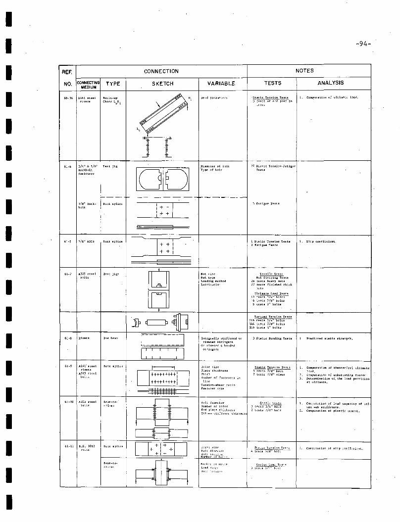
60-36 A141 steelrivets
IIII
REF.
NO. CONNECTINGMEDIUM
TYPE
Built-up
Chord LoU 1
CONNECTION
SKETCH
",\
VARIABLE
Bend parameters
TESTS
Static Tension Tests3testS~p;stin
truss
-94-
NOTES
ANALYSIS
1. Coml'.utation of ultimate load.
--- f------ - -.-- .---~._--------
IIII
61-4 3/4" & 5/8" Test jigRuckholtfasteners
7/'0" Huck- BUll splicebolt
n10101
:++C: + +___~_--J
Diameter of b::lLt"Type of bolt
27 Direct Tension-FatigueTests
3 Fatigue Tests
II
61-5 7/H" A325 Butt splice 1 Static Tension Tests2 Fatigue Tests
L Slip coefficient
IIIIIIIII
I61-7 AJ25 steel Test jigs
lJbolts
nt
jp~~61-8 Rivets Box beam I I
I : : : : : I61-9 A141' steel Butt splice I Irivets
A325 steel
I+++tt++++:
Ibolts
+++++++++1
11111111161-10 A325 steel Beam-to-
.~bolts column
0E3=J61-11 B.S. lOti) Butt splice 0+:i:+0bolts
Beam-to- pURc::olllmn
Nut sizeNut typeLoading methodLubrication
Integrally stiffened orriveted stringers
Or riveted & bondedstringers
Joinr sizePlate thicknessPitchNumber of fasteners in
lineTension-shear ratioFaste~er type
Bolt diameterNumber of boltsEnd plate thi.cknessColumn stiffener thicknes
']:)int SiZl'
!Solt diamL'~('r
B;J!l tensi('r,Nllmber of b;llts
Nllmber ;11 h~'l tsL;'<ld1:1;>[:
Tensile TestsNut Striping Tests
26 tests heavy nuts27 tests finished thick
Ultimate Load Tests10 tests 3/4" bolts
6 tests 7/8" bolts8 tests 1" bolts
Torqued Tension Tests216 tests 3/4" bolts144 tests 7/8" bolts216 tests 1" bolts
3 StBtic Bending Tests'
Static Tension Tests5 tests 7/8" bolt2 tests 7/8" rivet
Static Tests)test~
2 tests 7/8" bolt
Static Tensi (Ill Tests4 tesls 5/8" bolt
1. Predicted statia strength.
1. Computation of theoretical ultimateload. .
2. Computation of unbuttoning factor3. Determination of, the load partition
at ultimate.
1. Computation of load capacity of column web stiffeners.
2. Computation of plastic moment.
I. Computati.on of slip coefficient.
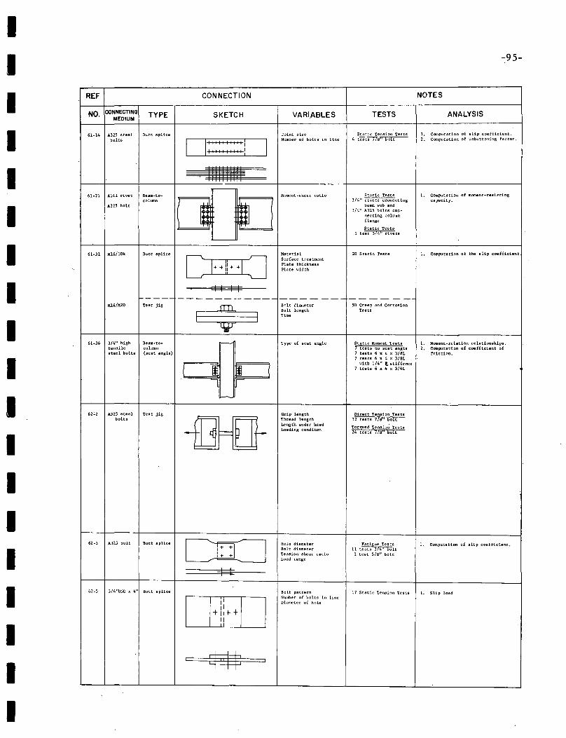
IIIIIIIIIIIIIIIIIII
-95-
REF CONNECTION NOTES
NO. CONNECTING TYPE SKETCH VARIABLES TESTS ANALYSISMEDIUM
61-14 A325 steel Butt splice Joint size Static Tension Tests 1. Computation of slip coefficient.bolts 0::::::::::1 I
Number of bolts in line 4 tests 7l~1I bolt 2. Computation of unbuttoning factor.
IIIIII1111 1
~-
61·21 A141 rivet Beam-to- Moment-shear ratio Static Tests 1. Computation of moment-resistingcolumn
~ m3/4" rivets connecting capacity.
A325 bolt beam web and3/4" A325 bolts con-
necting columnflange
Static Tests1 test 3/4" rivets
-
61·31 M.i6/10k Butt splice
CI++!jHOMaterial 20 Static Tests 1. COlDputation of the slip coefficientSurface treatmentPlate thicknessPlate width
I I I I----- ---------------------- --
Mi6/H20 Test jig
iBolt diameter 50 Creep and Corrosion
I IBolt length TestsTime
61·36 3/4" high Beam-to- r---' Type of seat angle Static Moment Tests 1. Moment-relation relationshillll.tensile column 7 tests no seat angle 2. Computation of coefficient ofsteel bolts (seat angle) 7 tests 6 x 4 x 3/8L friction.
7 tests 6 x 4 x 3/8L
J Wwith 1/4" t stiffener
7 tests 6 x 4 x 3/4L
'-----
62':'2 A325 steel Test jig Grip length Direct Tension Testsbolts
-fIH}Thread length 32 tests 7!a ll boltLength under head
Torqued Tenaio~ TestsLoading conditon
24 tests 7!8" bolt
62-3 A325 bolt Butt splice Ll:O Hole diameter Fatigue Tests 1. COOlputstion of slip coefficient.Bolt diameter 11 tests 3/4" bolt
1+ + Tension-shear ratio 1 t"est 5/8" boltLoad range
I I
62-5 3/4''UNC x 4'~ Butt splice Bolt pattern 17 Static Tension Tests 1. Slip load
IIN~ber of bolts in lineDiameter of hole
II+11++
II
I m I
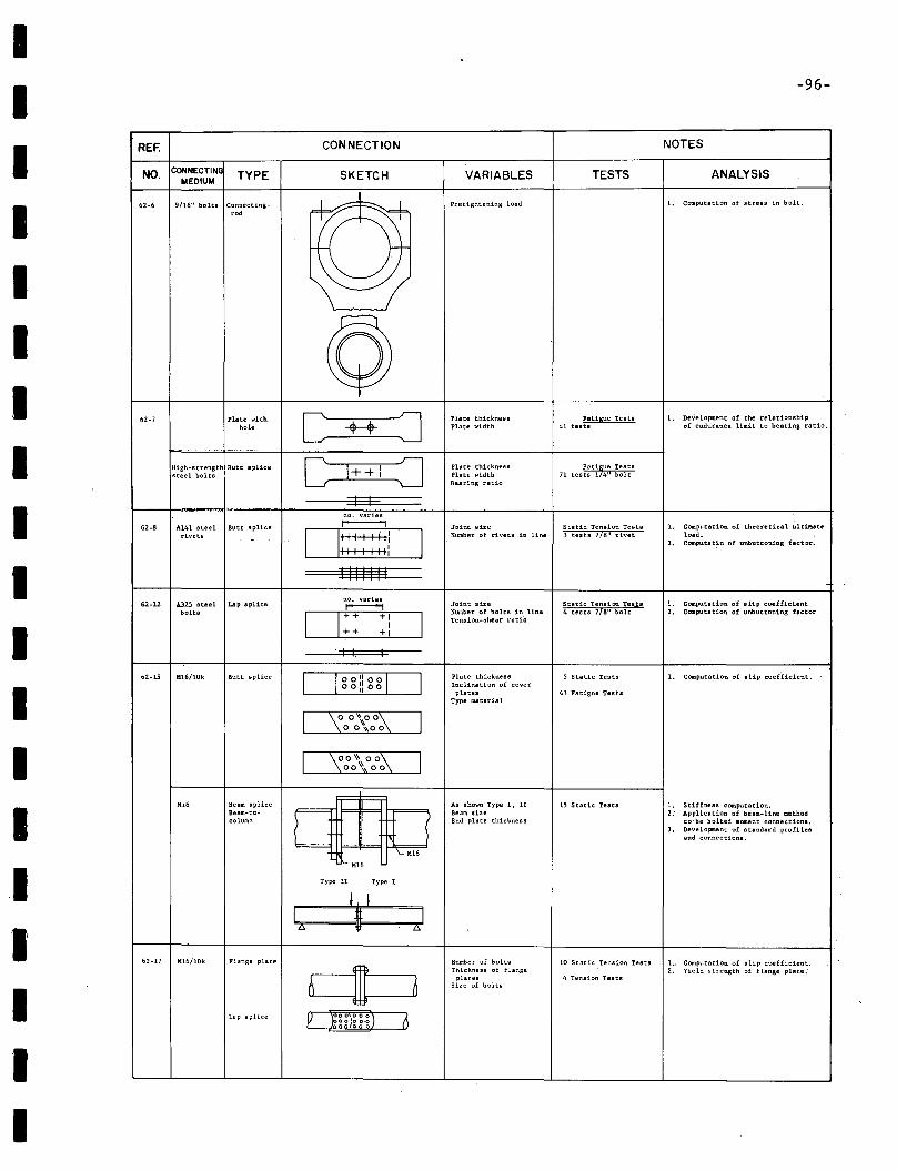
IIIIIIIIIIIIIIII'III
-96-
REF. CONNECTION NOTES
NO. CONNECTING TYPE SKETCH VARIABLES TESTS ANALYSISMEDIUM
62-6 9/16" bolts Connecting- --1--. Pretightening load 1. COll1putation of stress in bolt.
,ad
©62-7 Plate with C J Plate thickness Fatigue Tes t8 1. Development of the relationship
hole ++ Plate width 41 tests of endurance limit to bearing ratio.
.-- ----
C= :]High-strength Butt splice 1++ I Plate thickness71 tes~:ti,*~ ~~~~8steel bolts I Plate width
Bearing ratio
I I--no. varies
62-8 A141 steel Butt splice r---------1 Joint size Static Tension Tests 1. Computation of theoretical ultilUterivets 0:1
: :: ~ Ii INumber of rivets in line 3 tests 718 11 rivet load. . '- 2. C"omputatin of unbuttoning hc:tor.
"', IIIi
I III III
62-12 A.3.2.5 steel Lap spliceno. varies
Joint size Static Tension Tes.ts 1. Computation of slip coefficientr----1bolts D++ +1
INumber of bolts in line 4 tests 7/8" bolt 2. Computation of unbuttoning hc~or, Tension-shear ratio++ +1
I I, I
62·15 H16!lOk Butt splice ClooliooD Plate thickness 5 Static Tests 1. Computation of slip coet"ficient.Inclination of covero 0 ~l 00plates 43 Fatigue Tests
Type material
I \oo,\ooi\ I00 \\00
I ~O\\ 000: I00'\00
M16 Beam splice
C1== :==
QAs shown Type I, II 15 Static Tests 1. Stiffness computation.
Beam-to- Beam size 2: Application of beam-line methodcolumn End plate thickness to"be bolted moment connections.
3. Development of standard profilesand connections.
1== =f',..;. M16
Type II Type I
j II .1lt I
L> 'It L>
62-17 H16/10k FLange plate Number of bolts 10 Static Tension Tests 1.. Computation of slip coefficient.
c1Thickness of flange 2. Yield strength of flange plate:
0plates 4 Tension Tests
Size of bolts
Lap splice p ~OO\OoO) 6gp)06-g
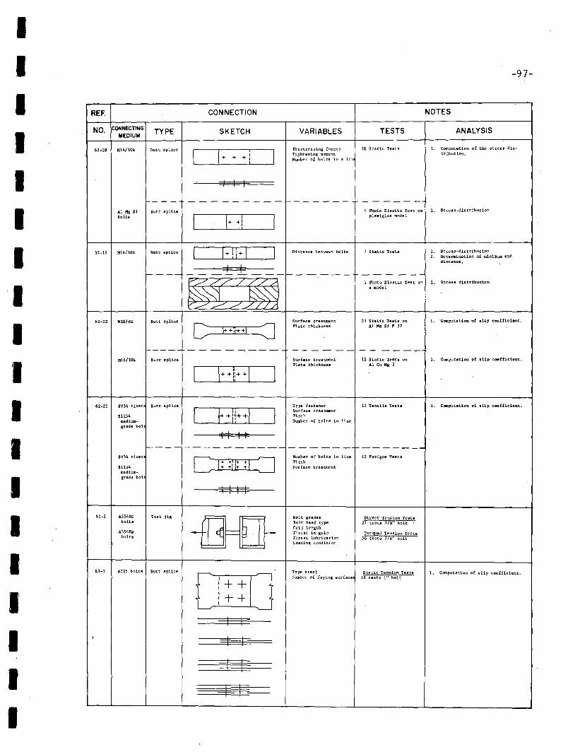
IIIIII
IIIIIIIIIIII
-97-
REF. CONNECTION NOTES
NO. CONNECTING TYPE SKETCH VARIABLES TESTS ANALYSISMEDIUM
62·18 Mi6/10k Butt splice Prestressing forces 10 Static Tests 1. Computation of the stress dis-
0+ ++! I Tightening moment tribution.Number of bolts in a lin
I I I
--- - -- - - - - -- 1--- ---- - ---- -Ai Kg 51 Butt splice 1 Photo Elastic Test on 1. Stres 8-dis tribution
Bolt8 I I· ·1 Iplexiglas mode 1
62·19 MiG/10k Butt splice~Distance between bolts 7 Static Tests 1. Stress -distribution
2. Determination of minimum enddistance.
I II-- --- - - -- --- I-- - - --- --- - --
~1 Photo Elastic Test on 1. Strus distribution
8 model
62-22 MIO/BG Butt splice
CSurface treatment 33 Static Tests on 1. Computation of aUp coefficint.
E·;;HI :J Plate thickness Al Kg 51 F 32
1----- - - - - ---- -- -- -- -- ---"":""'""Mi6/10k Butt splice Surface treatment 15 Static Testa on 1. Computation of • Up coefficient.
0++11+·0Plste thicknelll At Cu Kg 2
62·25 SV34 rivet Butt splice
CF+l!++I~Type fastener 12 Tensile Testa 1. C(llIlputation of slip coefficient.Surface treatment
B1154 Pitchmedium- Number of bolts in linegrade bol
I I I If---- ---------- ------ ...-------
SV34 rivet D: :I=:=JNumber of bolts in line 12 Fatigue Tests
:! I: PitchB1154 Surface treatment
medium-grade bol
I I I I
63-2 A354BC Test jig
-illl=UBolt grades Direct Tension Tests
bolts Bolt head type 27 tests 7/8" bolt
A354BDGrip lengthThread in gri p Torqued Tension Tests
bofts Thread lubrication 56 tests 7/'0" boltLoading condition
63-3 A325 bolts Butt splice - Type steel Static Tension Teats L Computation of slip coefficient.
I Number of faying surface 18 tests I" boltI + +II + +II
~ '--
I II I I
=----=s=~
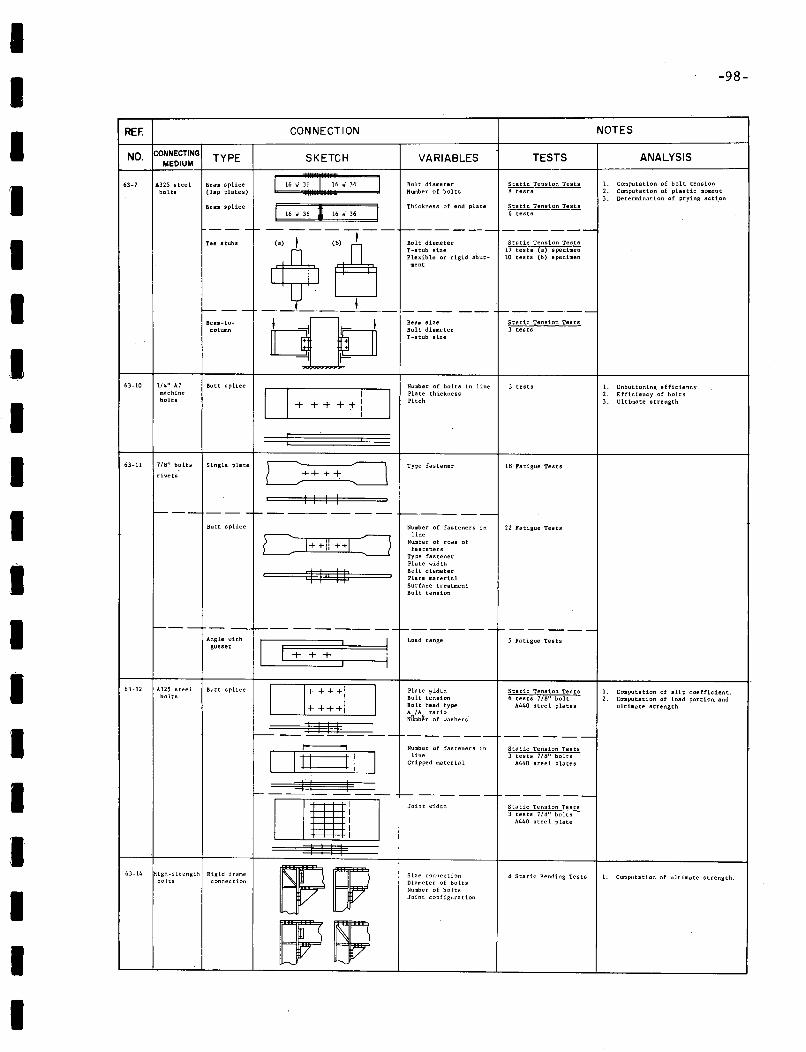
II
-98-
1. Vnbuttoning efficiency2. Effic1.ency of bolts3. Ultimate strength
ANALYSIS
1. Computation of bolt tension2. Computation of plastic moment3. Determination of prying seC1.on
NOTES
TESTS
Static Tension TestsH tests
3 tests
Static Tension Tests3 tests
Static Tension Tests6 tests
Static Tension Tests17 tests (a) specimen10 tests (b) specimen
VARIABLES
Number of bolts in linePlate thicknessPitch
Bolt diameterNumber of bolts
Beam sizeBolt diameterI-stub size
SKETCH
CONNECTION
O I I+ + + +:t-lL..--------!....--I
TYPE
Beam-tacolumn
Butt splice
Ream splice
Beam splice(lap plates) I 16 W~;=W=3=6==1
I I I Thickness of end plate16 'w 36 I 16 i 36
-- -I- -- ---- ---1------- ------Tee ",ub, (e> I (~b)I Bolt d"metorA, ~;:~~:l:i~; rigid .but-
~ ment
1---- _._I l_. --.. t---.-----
1/4" A7machinebolts
,\325 steelbolts
CONNECTINGMEDIUM
NO.
63-10
REF.
63-7
II
I
I
I
I
I 63-11 7/8" bolts Single plate
rivets
Type fastener ItJ·Patigue Tests
t-- -- - - -1--- ---.-- -- -- ~.----_.-
II
Butt splice
I I I I
==$$:$$ .
Number of fasteners inline
Number of rOJa offasteners
Type fastenerPlate widthBolt diameterPlate materialSurface treatmentBolt tension
22 Fatigue Tests
- -- t=---.-. -- - --- - -1---- -- -_.-. -I- - - - __
63-12 A325 steel Butt splicebolts
1. Computation of slip coefficLent.2. Computation of load portion. snd
ultimate strength
1. Computation of ultimate strength.
5 Fatigue Tests
ts Static Bending Tests
Static Tension Tests3 tests 7/8" bolts
A440 stce 1 plate
Static Tension Tests6 tests Ha" bolt
A440 steel plates
Static Tension tests) tests 7/8" bolts
A440 steel plates
------_.-
Size connectionDiameter of boltsNumber of boltsJoint configuration
Number of -fasteners inline
Gripped material
Joint ....idth
Load range
Plate ...idthBolt tensionBolt head typeAnlAs ratio .Number of washers
-_._._.-
1------- -----
-I I I II I
1+++ :
DL.2::::'.::1I::::::::::::::.1L-IIII Ic-OllIi
--1
I I I IRigid frame
con:lection
Angle withgusset
High.strengthbolts
~--
63-14
'II
I
I
II
I
I
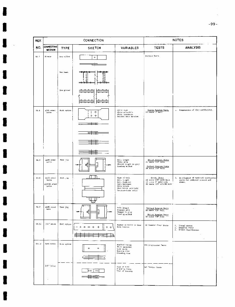
IIIIIIII
IIIIIIIIII
-99-
REF. CONNECTION NOTES
NO. CONNECTING TYPE SKETCH VARIABLES TESTS ANALYSISMEDIUM
64-2 Rivets Lap splice I I L::J Fatigue TestsI +I
I
Box beam r--w~; ,, II,II , II III I 1'1~ I ,I I
Box girder
00A325 steel [ ~o
Joint type Static Tension Tests 1- Computation of slip coefficient.64-4 Butt splice Ibolts ,+ Plate materials 29 tests 1" bolt,+ Plate thickness
I Initial bolt tension
I I
I I
::g
~64.-5 A490 steel Test jig -00- Bolt length Direct Tension Tests
bolts Tota 1 grip 21 tests 7/tj" boltThread length in gripLoading method Torqued Tension Tests
26 tests 7/1!J" bolt
64-6 A325 steel Test jig rTT1 Type of bolt Static Tests 1- Development of empiresl interactionbolts
IBolt length H6 tests 3/4" A325 bolt curve for combined tension andBolt diameter 10 tests 1" A325 bolt shear.
A3S4BD steel Bolt hardness 20 'tests 3/4" A354BD boltbolts Grip length
Test block materials
ITension-shear ratio
~64-7 A490 steel Test jig
~-Bolt length Torqued Tension Testsbolt Nominal grip 20 tests 7/8" boltThread in gripLoading method Direct Tension Tests
20 tests 778" bolt
64-11 7/8" bolts
1+Butt splice
ii +\Number of bolts in line 10 Tension Shear Tests 1. Normal stress+ + + + + + Bolt tension 2. Shearing force
3. Stress distribution
~I I I~64-12 SA90 bolts Butt splice Applied torque
~ il324 Compression Tesrs
+ +Plate materialType boltsTesting timeClamping time
~--- ----------- - ------------
5/8" bolts Type of holt 322 Tension Tests
1 1++ 1: ++1 IClamping forceTime of testing
~
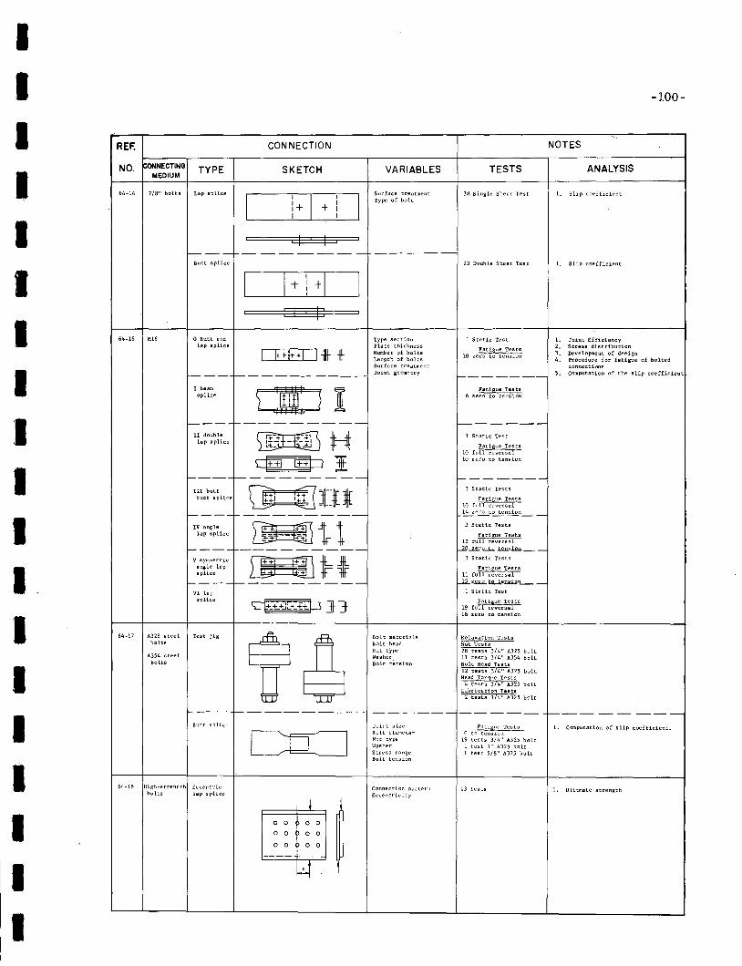
IIIIIIII
IIIIII,I
III
-100-
REF. CONNECTION NOTES
NO. !coNNECTING TYPE SKETCH VARIABLES TESTS ANALYSISMEDIUM
64-14 7/8" bolts Lap splice Surface treatment )8 Single Shear Test l. Slip coefficient
II
II
l Type of bolt
:+ I+ II I
I II
f----.- -----_.- -----Butt splice 23 Double Shear Iest l. Slip coefficient
I II +D+ III
riP64-16 M16 o Butt and Type section 1 Static Test l. Joint Efficiency
lap splice Plate thicknessFatigue Tests 2. Stress distribution
I F+!++I l-llt 1\- Number of bolts 3. Deve lopment of des 19nLength of bolts
10 zero to tensi:m4. Procedure for fatigue of bolted
Surface treatment connections
--- ---------- Joint geometry ------- 5. Computation of the slip coefficient
1 beam
K IFatigue Tests
splice ) ) 6 zero to tension
--- --------- f-------.-11 double lliffill H 1 Static Test
lap splice l=t:- - -.;J Fatigue Tests10 full reversal
qEJ @:J I 10 zero to tension
f----f---------- f-----.---III butt UI' :fi]lll 3 Static Tests
butt splice Fatigue Tests...... 110 full reversal
f-----f--------- ~eE£....t~nsion__
IV angle
~ t t 3 Static Tests
lap splice Fatigue Tests~ 12 full reversal
f---- --------- ~...llJ'o...ll~Wl.--V symmetric ill m$=+
3 Static Tests
angle lap Fatigue Testssplice ;S
11 full reversal
f----1---------- ~z~.t.2....!.e.!1ll2IL--_
VI lap 1 Static Test
splice
Q+++JC+++P ]-]tFatigue Tests
19 full reversal16 zero to tension
64-17 A325 steel Test jig
tr~Bolt materials Relaxation Tests
bolts Bolt head Nut TestsNut type ~3/4" A325 bolt
A354 steel Washer 11 tests 3/4" A354 boltbolts Bolt tension Bolt Head Tests
12 tests 3/4" A325 boltHead Torque Tests
4 tests 3/4" A325 boltLubrication Tests
2 tests 3/4" A325 bolt
f---- --------_.- ------------- 1---------Butt splice Joint size Fatigue Tests 1, Computation of slip coefficient.
c:ecJBolt diameter o to tensionNut type 19 tests 3/4" A325 boltWasher 1 rest 1" A325 boltStress range I test 5/8" A325 holtBolt tension
64-18 High-strength Eccentric Connection pattern 13 tests 1, Ultimate strengthbolts lap splice Eccentricity
I I I0 o ~ 0 0
~0 0 t 0 0
0 0 0 0
----~--
L:.t I
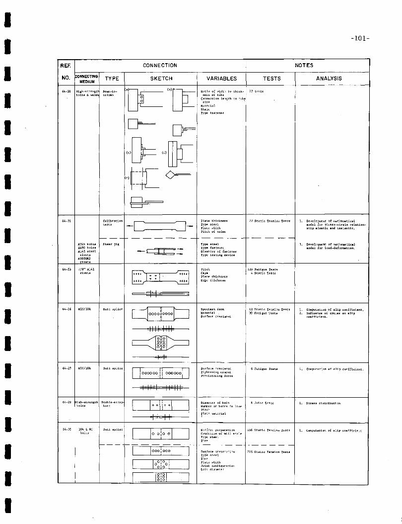
IIIIIIIIIIIIIIIIIII
-101-
REF. CONNECTION NOTES
NO. CONNECTING TYPE SKETCH VARIABLES TESTS ANALYSISMEDIUM
64-20 High-strengt Beam-to- "OCT~Ratio of width to thick- 27 testa
bolts & weld column ness of tubeConnection length to tub~
sizeMaterialShapeType fastener
cr= [Js=
{}= '''ffi[·,t-~c 0=-
gs64-22 Calibration -c ~-
Plate thickness 22 Static Tension Tests L Developnent of mathern.tieeltests Type steel model for stress-strain relation-
plate width ship elastic and inel811tic.,pitch of holes
I-- --I- -- -- -- -- -- - -- -- -- - -- -- --A325 bolts Shear jig Type steel L DeveloJ:Ul;ent of mathematic81A490 bolts
- e::::t:::t::b:7= Type fastener model for load-deformation.A141 steel Diameter of fastenerrivets Type testing device
A'OtGll2rivets
64-25 7/8" A141 Pitch 120 Fatigue Testsrivets
++++ I: +f++ Gage 4 Static Tests+ I plate thickness+ Edge thickness++++ ..-t+
I I
64-26 M16/lOk Butt splice [joooolioooob Specimen, form 12 Static Tension Tests 1. Computation of slip coefficient.Material 30 Fatigue Teats 2. Influence of cycles on slipSu.rface treatment coefficient.
IIII 1I1I
~811 8010I I
64-27 M16/l0k Buh splice Surface treatment 6 Fatigue Teats[100000011 0000000 1. Computation of slip coefficient.Tightening momentprestressing force
III111 I1III1
64-29 igh-strength Double-strap CIHli++l=J Diameter of bolt 8 Joint Tests 1. Stress distributionbolts butt Number of bolts in line
Pitch
I I I Iflate material
64-35 10k & 8C Butt splice Dooio°DSurface preparation 156 Static Tension Tests 1. Computation of slip coefficient
bolts Condition of mill scaleType steelTime
f--- f--------r-- ---- r------c=J 000 j000CJ Surface preparation 216 Static Tension TestsType steelTime
~plate widthoI 0Joint configuration0'0 Bolt diameter
I [[[I I
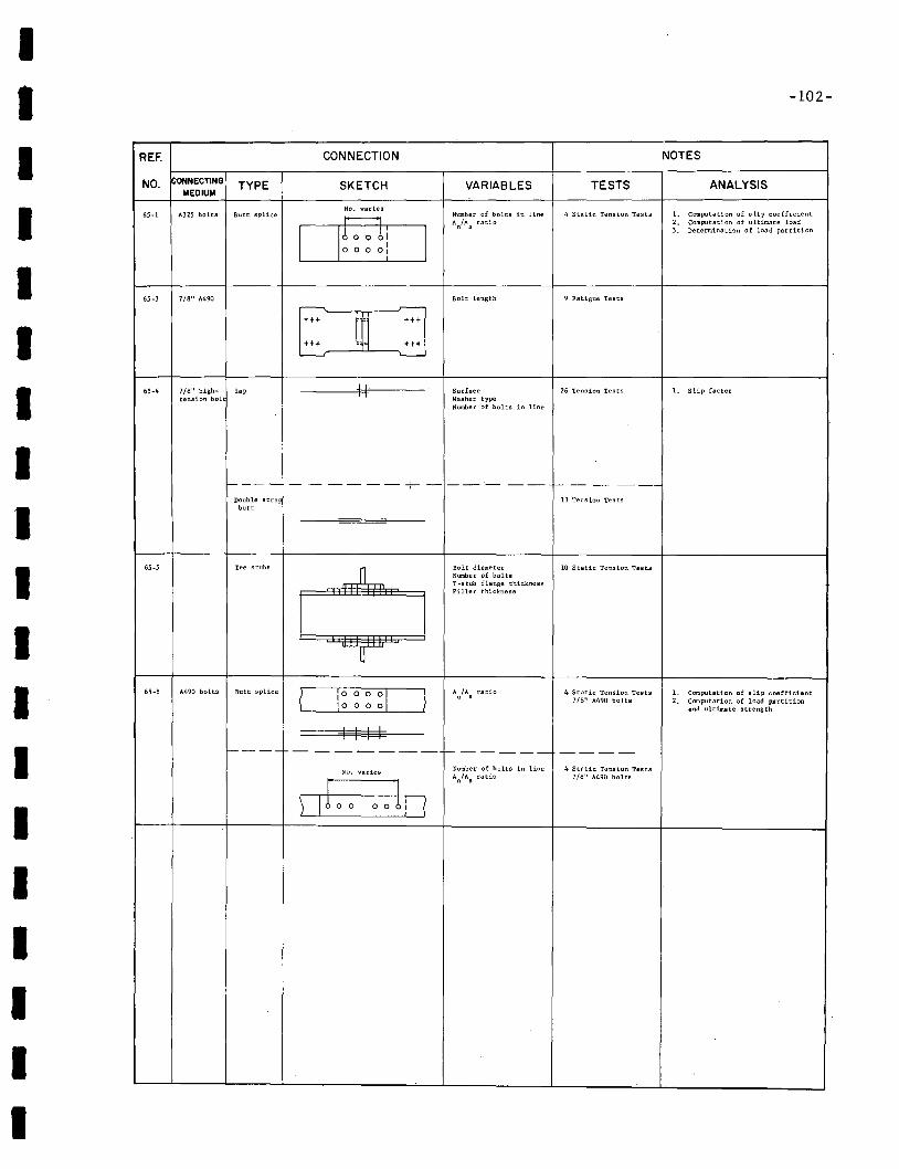
IIIIIIIIIIIIIIIIIII
-102-
REF. CONNECTION NOTES
NO. ONNECTING TYPE SKETCH VARIABLES TESTS ANALYSISMEDIUM
No. varies4 Static Tension Tests65-1 A325 bolts Butt splice om Number of bolts in line 1. Computation of s lip coefficient
AnlAs ratio 2. Computation of ultimate load3. Determination of load partition
~
65-3 7/8" A490 Bolt' length 9 Fatigue Tests
~ r--
+t+
m+t+
+H +t+L.-.---J '---
65·4 7/8" bigh- lap II Surface 26 Tension Tests 1. Slip factortension bol Washer type
Number of bolts in line
f---- - ----- - --- --- f- - - ----Double stra 13 Tens ion Tes tsbutt
65-5 Tee stubs
.-JLBolt diameter 10 Static Tension TestsNumber of boltsI-stub flange thicknessFiller thickness
U
~65-8 A490 bolts Butt splice
i~0 0
~DA fA ratio 4 Static Tension Tests 1. Computation of slip coefficient
u •7/8" A490 bolts 2. Computation of load partition
0 0 snd ultimate strength
I I I If---- - --------- f------ -----
No. varies Number of bolts in line 4 Static Tenaion TestsAnlA
sratio 718" A490 bolts
ufo In0 0 0
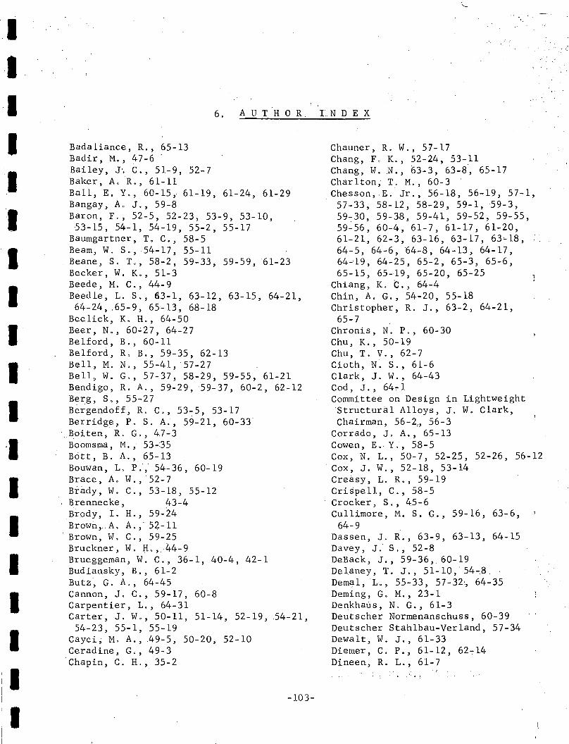
IIIIIIIIIII
IIIIIII
6. AUTHOR.
Bada1iance, R., 65-13Badir, M" 47-6Bailey, J~ C., 51-9, 52-7Baker, A.R" 61-11Ball, E. Y., 60-15~ 61-19, 61-24, 61-29Bangay, A. J., 59-8Baron, F., 52-5, 52-23, 53-9, 53-10,53-15, 54-1, 54-19, 55-2, 55-17
Baumgartner, To C., 58-5Beam, W. So, 54-17, 55-11Beane, S, T" 58-2, 59-33, 59-59, 61-23Becker, W. Ko, 51-3Beede, M. C., 44-9Beedle, L. S., 63-1, 63-12, 63-15, 64-21,64-24, .65-9, 65~13, 68-18
Bee1ick, K. H., 64-50Beer, No, 60~27, 64-27Belford, B., 60-11Belford, R, B., 59-35, 62-13Bell, M. N., 55-41,57-27Bell, W. G., 57-37, 58-29, 59-55, 61-21Bendigo, R. A., 59-29, ~9-37, 60-2, 62-12Berg, So, 55-27Bergendoff, R. C., 53~5, 53-17Berridge, P. S. A., 59-21, 60-33
. Boiten, R. G., 47-3Boomsma, M., 53-35Britt, B. A., 65-13Bouwan, L P., 54-36, 60-19Brace, Ao W.,52-7Brady, W. C., 53-18, 55-12Brennecke, 43-4Brody, I. H" 59-24Brown;A. A., 52-11Brown, W. C" 59-25Bruckner, W. H., 44-9Brueggeman, W. C., 36-1, 40-4, 42-1Budiansky, B., 61-2Butz~ G. A., 64-45Cannon, Jo C" 59-17, 60-8Carpentier, L., 64-31Carter, J. We' 50~11, 51-14, 52-19, 54-21,
54-23, 55-1, 55-19Cayci; M. A., 49-5, 50-20, 52-10Ceradine, G" 49-3Chapin, C. H., 35-2
-103-
.,"TN D E X
Chauner, R. W" 57-17Chang, F. K., 5~-24, 53-11Chang, W. N., 63-3, 63-8, 65-17Charlton; T. M., 60-3Chesson,E. Jr., 56-18, 56-19, 57-1,
. 57-33, 58-12, 58-29, 59-1,59-3,59~30, 59-38, 59-41, 59-52, 59-55,59-56, 60-4, 61-7, 61-17, 61-20,61-21, 62-3, 63-16, 63-17, 63~18,
64-5, 64-6, 64-8, 64-13, 64-17,64~19, 64-25, 65-2, 65-3, 65-6,65-15, 65-19, 65-20, 65-25
Chiang, K. C., 64-4Chin, A, G., 54-20, 55-18Christopher, R. J., 63-2, 64-21,
65-7Chronis, N. P., 60-30Chu, K., 50-19Chu, T. V., 62-7Cioth, N. S" 61-6Clark, J. W., 64-43Cod, J., 64- 1Committee on Design in Lightweight'Struttura1 Alloys, J. W. Clark,Chairman, 56-2" 56-3
Corrado, J. A., 65-13Cowen, E. Y., 58-5Cox, N. L., 50-7, 52-25, 52-26, 56-12
. Cox, J. W., 52-18, 53-14Cre~sy,L. R., 59-19Crispell, C., 58-5Crocker, S., 45-6Cullimore, M. S. G., 59-16, 63-6,
64-9Dassen, J. R., 63-9, 63-13, 64-15Davey, J. S., 52-8DeBack, J., 59-36, 60-19Delaney, T. J., 51-10, 54-8.Dema1,L., 55-33, 57-32:, 64-35Deming, G. M., 23-1Denkhaus, No G., 61-3Deutscher Normenanschuss, 60-39Deutscher Stah1bau-Ver1and, 57-34Dewalt, W. J., 61-33Diemer, C. P., 61-12, 62-14Dineen, R. Lo, 61-7
.". ,
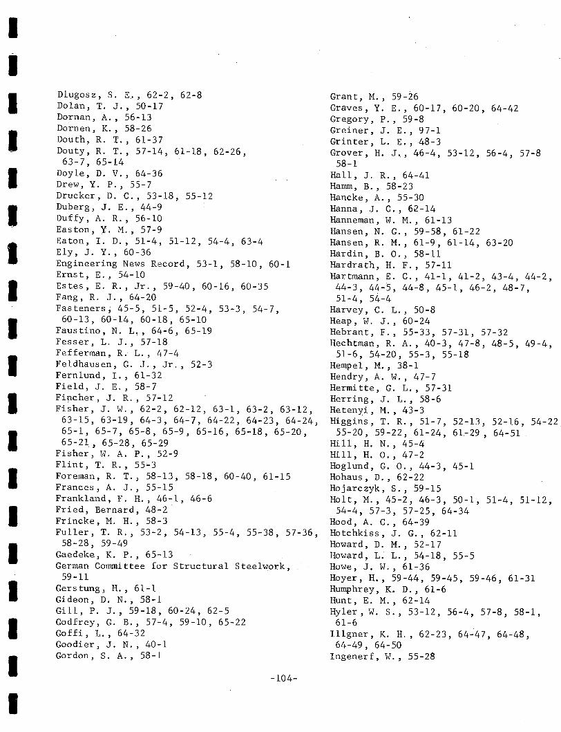
IIIIIIIIIIIIIIIIIII
Dlugosz, S. E., 62-2, 62-8Dolan, T. J., 50-17Dornan, A., 56-13Dornen, K., 58-26Douth, R. T., 61-37Douty, R. T., 57-14, 61-18, 62-26,63-7, 65-14
Doyle, D. V., 64-36Drew, Y. P., 55-7Drucker, D. C., 53-18, 55-12Duberg, J. E., 44-9Duffy, A. R., 56-10Easton, Y. M., 57-9Eaton, 1. D., 51-4, 51-12, 54-4, 63-4Ely, J. Y., 60-36Engineering News Record, 53-1, 58-10, 60-1Ernst, E., 54-10Estes, E. R., Jr., 59-40, 60-16, 60-35Fang, R. J., 64-20Fasteners; 45-5, 51-5, 52-4, 53-3, 54-7,
60-13, 60-14, 60-18, 65-10Faustino, N. L" 64-6, 65-19Fesser, L. J., 57-18Fefferman, R. L., 47-4Fe1dhausen, G. J., Jr., 52-3Fern1und, I., 61-32Field, J. E., 58-7Fi~cher, J. R., 57-12Fisher, J. W., 62-2, 62-12, 63-1, 63-2, 63-12,
63-15, 63-19, 64-3, 64-7, 64-22, 64-23, 64-24,65-1, 65-7, 65-8, 65-9, 65-16, 65-18, 65-20,65-21, 65-28, 65-29
Fisher, W. A. P., 52-9Flint, T. R., 55~3
Foreman, R. T., 58-13, 58-18, 60-40, 61-15Frances, A. J., 55-15Frankland, F. H., 46-1, 46-6Fried, Bernard, 48-2Frincke, M. H., 58-3Fuller, T. R., 53-2, 54-13, 55-4, 55-38, 57-36,
58-28, 59-49Gaedeke, K. P., 65-13German Committee for Structural Steelwork,
59-11Gerstung, H., 61-1Gideon, D. N., 58-1Gill, P. J., 59-18, 60-24, 62-5Godfrey, G. B., 57-4, 59-10, 65-22Goffi, L., 64-32Goodier, J. N., 40-1Gordon, S. A., 58-1
-104-
Grant, M., 59-2.6Graves, Y. E., 60-17, 60-20, 64-42Gregory, P., 59-8Greiner, J. E., 97-1Grinter, L. E. ,48-3Grover, H. J., 46-4,53-12,56-4,57-8
58-1Hall, J. R., 64-41Hamm, B., 58-23Hancke, A., 55-30Hanna, J. C., 62-14Hanneman, W. M., 61-13Hansen, N. G., 59-58, 61-22Hansen, R. M., 61-9,61-14, 63-20Hardin, B. 0., 58-11Hardrath, H. F., 57-11Hartmann, E. C., 41-1, 41-2, 43-4, 44-2,44-3, 44-5, 44-8, 45-1, 46-2, 48-7,51-4, 54--4
Harvey, C. L., 50-8Heap, W. J., 60-24Hebrant, F., 55-33, 57-31, 57-32Hechtman, R. A., 40-3, 47-8, 48-5, 49-4,
51-6, 54~20i 55-3, 55-18Hempel, M., 38-1Hendry, A. W., 47-7Hermitte, G. L., 57-31Herring, J. L., 58-6Hetenyi, M., 43-3Higgins, T. R., 51-7, 52-13, 52-16, 54-22
55-20, 59-:-22, 61-24, 61.-29, 64-51Hill, H. N., 45-4Hill, H. 0., 47-2Hoglund, G. 0., 44-3, 45-1Hohaus, D., 62-22Hojarczyk, S., 59-15Holt, M., 45-2, 46-3, 50-1, 51-4, 51-12,
54-4, 57-3, 57-25, 64-34Hood, A. C., 64-39Hotchkiss, J. G., 62-11Howard, D. M., 52-17Howard, L. L., 54-18, 55-5Howe, J. w., 61-36Hoyer, H., 59-44, 59-45, 59-46, 61-31Humphrey, K. D., 61-6Hunt, E. M., 62-14Hyler, W. S., 53-12, 56-4, 57-8, 58-1,
61-6Il1gner, K. H., 62-23, 64-47, 64-48,64-49, 64-50
Ingenerf, W., 55-28

IIIIIIIIIIIIIIIIIII
Instit~tion of Structural Engineers, 57-10Iron Age; 59-31Irvan~ W. G., 57-20Jackson, L. R., 46-4Jenkins, J. W., 58~6
Johnson, L. G~, 59-17,60-8,64-14Johnston, B., 40-3, 42-3, 52-24Jones, J" 58-14Jones, R.', 61-11Kaplan, S., 59-5Ka~inski, J., .59-15Kasuha, R" 62-6Kellermann, R., '55-29Kelly, J. J., 48-1Kenworthy, K. J., 54-1, 55-2Kinney, J. W., 59-61, 61-30Klein, H. -CH, 55-29K1oppe1, K., 64-16Knoell, A. C., 62-3Koepsell, P. L., 55-3Komatsuhara, M., 61-38, 62-25Konishi, I., 64-28Korber, F., 38-1Kovac, J. J., 49-2Kreis1e, L. F., 52-15Krickenberger, C. F., Jr., 57-1Kulak, G. L., 65-7Kuzmanovic, B. 0., 60-31Lancaster, N., 59-14Langdon, Howard H., 48-2Langhaar, H. L., 47-4Lappo, T., 50-12LaRoy, H. E., 57-23Larson, E. W., Jr., 52-5, 52-23, 53-9,53-10,
53-15, 54-19; 55-2, 55-17Laub, W. H~, 54-2Lathrop, R. P., 64-1Leahey, T. F" 54-5, 54-13, 54-16, 55-4Legate, A. C" 57-22Lehman, F. G., 60-6Lenzen, K. H., 49-7, 49-9, 50-16, 54-21, 55-19Leon~ E. V., 61-35Levy, S., 42-2, 64-38Lewis, E. M., 57-9, 60-32Lewitt, C. W., 59-1, 59-3, 59-38, 59-53, 60-4,
63-16Leybo1d, H. A., 61-8Lind, H. H., 50-2~, 60-10Lindner, C. W., 49-11, 50-15Lipson, C., 48-4Loubser, R. S., 63-5
";105-
"';',';
Louw, J .Mi, ~ 5h'30Lu, z. A'.. ,5'i'''',~'i:~9''S.9~ ,61;;'23Lys t, J. i:r~, 44::;:5" '.Madison, R. B~ ,<56,-5, 59':'59, 61-23Man~y; G. A., 44-1, 45-3, 46":5, 46-7,
':{.'. '
46:':,~ ".Marcin,. S~:3. , 60-5Martin, H. ,59--,27Mas, E" 64-35Massard, J. M" 52-1, 58-4Massonet,.C., 57.,.31, 57-32Mathison, W., 59-51Mattheisen, R. B., 57-3McCalley, J.,C., 54-23, 55-1McCa1lJ!IIlon, L. B., 49-11, 50-15McC1ow,,3. n.;· 50-17'McDonald, ,D., 58-4MCFarland, W.J.; 56.,.7McGuire,W., '61-37, 62-26, 63-7, 65-14McMullen, A.,C., 60-29McPherson,A.E., 42-2Merritt, F. S. ,50-10Michalos, ,J., 57-30,Milek, W. A., 64-42:Millard, E., H., 47-1Miller, M. A., 44-3, 45-1, 48-7Milliken,M. P., 50-2Mitchell, W. D., 55-9Mohler, K., 54-11, 58-22, 59-43, 62-15Mod,sseiff, L. S., 44-8Moor~ ,." H~":;"'~:~':' "4.6-?f..., ./:.!~ .. ':;.Moore, R. L., 44-8, 45-4Mordfin, L., 55-34, 57-22Mount, E. H., 42,':'3Munse, W. H., 49-:6,.50-7,50-20,51-2,
51-3, 52-f, 52~2~ 52-10, 52-16, 52-26,53-2, 53-:5, 54..5; 54-13, 54-15, 55-4,55-11, 55~14; 55..16, 55-19; 55-39,56-8,56-11~ 56~12, 56-18, 57-1~ 57-16, 57-33,57-36, 58-12, 58-28, 58-29, 59-1, 59.,.2,59-4,' 59-39"" .59-32,' 59-38, 59-41, 59-49,59-55, 59-56, 60-4, 60-7, 61-4,61-5~
61-7 61-17 61-20'61~21 61-27 62.,.3"0. " .. ~.' , ,63-16,.63-17,.63,.,18,64-6,64-17,64-35,65-2, 65-25
Musnitsky,W. D., 57~5
Naka, T.; 64-:30Navy Department", 50-18Nawrat, T., 59.,.15Nelson, H. M.; 53-13Newmark,N.M., 52-12, 54-15, 55-14, 55-lE
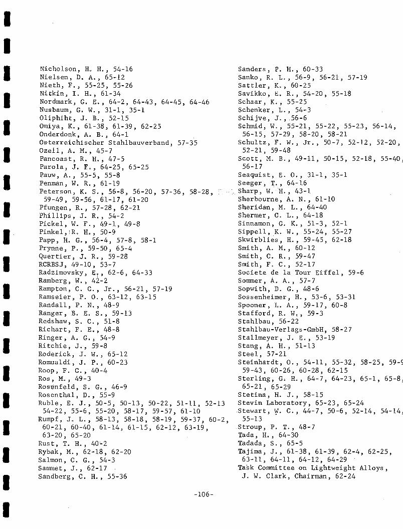
IIIIIIIIIIIIIIIIIII
Nicholson, H. H' J 54-16Nielsen, D. A., 65-12Nieth, F., 55-25, 55-26Nitkin, I. H., 61-34Nordmark, G. E., 64-2, 64-43, 64-45, 64-46Nusbaum, G. W., 31-1, 35-101iphiht, J. B., 52-15Omiya, K., 61-38, 61-39, 62-25Onderdonk, A. B., 64-1Os'terreichischer Stahlbauverband, 57-35Ozell, A. M., 45-7Pancoast, R. H., 47-5Parola, J. F., 64-25, 65-25Pauw, A., 55-5, 55-8Penman, W. R., 61-19Peterson, K. s., 56-8, 56-20, 57-36, 58-28,
59-49, 59-56, 61-17, 61-20Pfungen, R., 57-28, 62-21Phillips, J. R., 54-2Pickel, W. F., 49-1, 49-8Pinkel,iR. H., 50-9Papp, H. G., 56-4, 57-8, 58-1Prynne, P., 59-50, 65-4Quer ti er, J. R., 59 - 28RCRBSJ, 49-10, 53-7Radzimovsky, E~, 62-6, 64-33Ramberg, W., 42-2Ramp ton , C. C., Jr., 56-21, 57-19Ramseier, P. 0., 63-12, 63-15Randall, P. N., 48-9Ranger, B. E. S., 59-13Redshaw, S. C., 51-8Richart, F. E., 48-8Ringer, A. G., 54-9Ritchie, J., 59-8Roderick, J. W., 65-12Romualdi, J. P., 60-23Roop, F. C., 40-4Ros, M., 49-3Rosenfeld, S. G., 46-9Rosenthal, D., 55-9Ruble, E. J., 50-5, 50-13, 50-22, 51-11, 52-13
54-22, 55-6, 55-20, 58-17, 59-57, 61-10Rumpf, Jo L., 58-13, 58-18, 58-19, 59-37, 60-2,60~21, 60-40, 61-14, 61-15, 62-12, 63-19,63-20, 65-20
Rust, T. H., 40~2
Rybak, M., 62-18, 62-20Salmon, C. G., 54-3Sammet, J., 62-17Sandberg, C. H., 55-36
-106-
Sanders, P. H., 60-33Sanko, R. L., 56-9, 56-21, 57-19Sattler, K., 60-25Savikko, E. R., 54-20, 55-18Schaar, K., 55-25Schenker, L., 54-3Schijve, J., 56-6Schmid, W., 55-21, 55-22, 55-23, 56-14,
56-15, 57-29, 58-20, 58-21Schultz, F. W., Jr., 50-7, 52-12, 52-20,
52-21, 59-48Scott, M. B., 49-11, 50-15, 52-18, 55-40,
56-17Seaquist, E. 0., 31-1, 35-1Seeger, ~., 64-16
•. Sharp~ W."H., 43-1Sherbourne, A. N., 61-10Sheridan, M. L., 64-40Shermer, C. L., 64-18Sinnamon, G. K., 51-3, 52-1Sippell, K. W., 55-24, 55-27Skwirblies, H., 59-45, 62-18Smith, A. M., 60-12Smith, C. R., 59-47Smith, F. C., 52-17Societe de la Tour Eiffel, 59-6Sommer, A. A., 57-7Sopwith, D. G., 48-6Sossenheimer, H., 53-6, 53-31Spooner, L. A., 59-17, 60-8Stafford, R. W!, 59-3Stahlbau, 56-22Stahlbau-Verlags-GmbH, 58-27Stallmeyer, J. E., 53-19Stang, A. H., 51-13Steel, 57-21Steinhardt, 0., 54-11, 55-32, 58-25, 59-5
59-43, 60-26, 60-28, 62-15Sterling, Go H., 64-7, 64-23, 65-1, 65-8,
65-21, 65-29Stetiria, H. J., 58-15Stevin Laboratory, 65-23, 65-24Stewart, W. C., 44-7, 50-6, 52-14, 54-14,
55-13Stroup, P. T., 48-7Tada, H., 64-30Tadada, S., 65-5Tajima, J., 61-38, 61-39, 62-4, 62-25,63-11, 64-11, 64-12, 64-29
Task Committee on Lightweight Alloys,J. W. Clark, Chairman, 62-24
IIIII~
IIIIIIIIIIIIII
Tate, M. B., 46-9 Yura, J. A., 65-13Taylor, J. C., 60-9 Zamboky, A. N., 44-4, 46-2Templin, R. L., 41-2, 54-12 Zar, M., 58-9, 61-26Thrasher, J. Q., 57-13 Zardman, F., 59-47Thur1imann, B., 57-26, 60-34 aiemba, St., 62-20Toint, E., 59-42 Zweig, B. A., 61-25Tokunaga, A., 65-5Tomonaga, K., 63-11, 64-29Treanor, H. E., 57-23Trittler, G., 56-13Troup, E. W. J., 64-5, 65-21Upton, K. A., 64-9, 64-44Vasarhelyi, D. D., 56-5, 57-2, 57-15, 57-17,
58-2, 59-33, 59-59, 60-9, 61-23, 63-3, 63-8,64-4, 65-17
Vasishth, C., 57-2, 57-15, 59-59, 60-9, 60-22,61-23
Viglione, J., 57-6, 65-11Viner, J. A., 61-7Vogt, F., 47-9Wallaert, J. J., 64-23, 65-16, 65-29Wallner, H., 64-27Waltermire, W. G., 58-16, 62-1Watson, I., 64-10Weber, N. E., 62-9Wescoat, C. F., 43-4, 44-2Whaley, R. E., 57-11White, M. W., 57-26White, R. N., 64-20Whitmore, R. E., 52-6Whittem~re, H. L., 31-1, 35-1Wiedemann, J., 62-16Wiegand, H., 55-25, 62-23, 64-49, 64-50Williams, W. L., 58-6Wilson, W. M., 44-6, 44-9, 45-7, 46-4, 49~6, 50-20,
51-1Wilson, W. R., 55-37Winter, G., 56-1, 56-16Wolf, W., 58-24, 59-23Wright, D. T., 51-2, 52-2, 52-22, 54-15, 55-14,
55-16, 57-9, 60-32Wright, W., 63-10Wu, T. W., 61- 2Wy1y, L. T., 49-11, 50-4, 50-11, 50-15, 54-21;
54-23, 55-1, 55-19, 55-46, 56-17, 57-23, 57-24Yamada, M., 63-14Yeun, C. Y., 60-9Yeakel, W. R., 62-10Yoshimoto, S., 65-5Young, D. R., 51-6, 54-20, 55-18Young, W. C., 59-7
-107-
I N D E X
IIIIIIIIIIIIIIIIIII
7. SUB J E C T
A
AISC Specifications, 62-11, 64-20Alloy Steel Bolts, 46-9, 59-27, 65-7Aluminum Alloy
Joints, 44-3, 44-8, 45-1, 46-2, 48-7,52-6, 53-4, 54-4, 55-34, 57-8, 57-22,59-16, 64-24, 64-37, 64-46
Material, 50-2, 53-1, 56-2, 56-3, 62-24,64-2, 64-45
Plates, 42-3, 46-9, 61-31, 64-45Rivets, 44-2, 45-2, 51-9, 52-7, 54-8
Aluminum Butt Joints, 57-8, 59-16Aluminum Highway Bridges, 51-10, 62-24Aluminum Riveted Joints, 40-4, 44-2, 44-8,
45-1, 45-4, 51-8, 52-7~ 55-34, 61-8Analogous Grid, 48-3Analysis
Bolted Plate Splices, 64-3, 61-32Columns, 57-26
Assembly Clearance, 62-6Assembly of Joints, 54-7, 59-11ASTM, 60-16, 64-13Axial Load, 53-4, 60-21
B
Bakelite Joints, 52-6Balanced Design
Bolted Joints, 54-2, 55~14, 55-15, 63-1Riveted Joints, 58-12
Beam-to-Co1umn Joints, 40-3, 42-3, 47-8,54-3, 58-4, 59-13, 59-14, 61-10, 61-21,63-7, 63-14, 64-20, 64-21, 65-12
Bearing of Rivets, 55-19Bearing Pressure, 51-3, 52-1, 53-5, 53-7,
57-24, 58-14, 59-1, 59-32, 60-35, 64-25Bearing Ratio, 51-3, 52-1, 58-14, 59-1,
59-32, 64-25Bearing Strength, 59-34, 62-15Bearing Stresses, 59-4, 62-7Bearing-Tension Ratio, 59-1Bending Stresses of Bolts, 62-6Beryllium Bolts, 60-30Bolt
Assembly, 49-1, 61-27, 62-6
-108-
Calibration, 59-29~ 59-37, 62-2Characteristics, 23-1, 51-7, 52-8,
58-23, 62-23, 63-4, 63-6, 64-39,65-2
Clearance, 54-4, 62-19Diameter, 63-2Fit, 46-4Holes, 50-11, 91-32, 64-9High Strength (see high strength
bolts)Load, 35-1, 46-9, 59-18, 59-38,
61-3Load-Elongation Curves, 50-9, 62-17Material, 35-1, 46-6, 63-6 .Preload, 49-2, 52-8~~53~16,:59-18,
60-28; 61-11, 65-24Proof Load, 60-13, 64-15Properties, 50-8, 60-19, 62-23Shear Area, 60-2, 61-14, 61-15Shear Strength, 47-5, 60-30, 61-14Shear Test, 57-18Stresses, 43-3, 50-2Tensile Stress, 59-31Tension, 46-8, 48-3, 50-17, 51-6,
52-2, 55-8, 55-14, 56-9, 57-1,57-27, 58-6, 58-19, 60-13, 60-19,60-34, 61-18, 61-24, 62-2, 62-3,63-7, 64-5, 64-23, 64-38, 65-1
Tightening, 50-2, 59-41, 61-13,. 61-24, 61-25, 61-27, 61-28, 62-13Bolted Joint Efficiency, 56-8Bolted Joint Strength, 59-31, 60-29Bolted Joints, 49-4, 50-3, 50-4, 50-5,
50-17, 51-7, 52-8, 52-14, 53-1, 54-5,55-1, 55-10, 55-11, 55-14, 55-15,55-16, 55-17, 55-21, 56-1, 56-5,56-7, 56-8, 56-10, 56-13, 57-2, ~7-9,
57-15, 57-17, 57-21, 57-24, 58-2,58-4, 58-7, 58-13, 58-18, 58-20,58-22, 58-24, 58-25, 59-9, 59-11,59-12,59-30,59-33,59-40,59-41,59-48, 59-50, 59-51, 60-3, 60-5,60-7, 60-16, 60-21, 60-22, 60-24,60-25, 60-26, 60-28, 60-29, 60-33,
-109-
54-358-461-10
D
Column Anchorages,Column Base Joint,Column Stiffeners,Columns
Axially Loaded, 57-26Eccentrically Loaded, 57-26Strength, 57-26
Combined Shear and Tension StrengthBolts, 59-3, 62-11, 64-6, 64-23,".' 64i-n, :65~2Rivets, 56-12, 62-11
Combined Stress, 52-16, 53-17Compact Bolted Joints, 61-15, 63-1Compression Test, 55-18, 58-14, 58-19,
59-32Construction, 51-5, 62-11
Building, 55-20High Strength Bolted, 54-10, 55-22,
60-26, 62-10, 65-10Welded, 62-10
Contact Surface Treatment, 59-11, 59-36Continuous Frame Joints, 54-3Cost
Bolts vs. Rivets, 59-19, 60-35,61-12
Fasteners, 58-15, 60-20'Installing High Strength Bolts,
37-25, 52-13Cover Plates, 57-26
. Creep, 57-22, 58-6, 65-24Critical Buckling Load for Plate
Girder, 60-9Cumulative Fatigue Damage, 59-49
C
60-34, 61-4, 61-5, 61-9, 61-14, 61-17,61-18, 61-23, 61-30, 61-31, 61-32,62-4, 62-7, 62-15, ,62-16, 62-17, 62-19,62-21 62-23 62-2562-26 63-1' 63-5, , , , , ,63-6, 63-8, 63-11, 63-13, 63-14, 64-1,64-8, 64-9, 64-11, 64-12, 64-14, 64-15,64-16, 64-17, 64-19, 64-20, 64-21, ~:
64-22, 64~23, 64-24, 64-26, 64-28,64-29, 64-32, 64-33, 64-35, 64-36,64-37, 64-38, 65-1, 65-5, 65-6, 65-1,65-8, 65-10, 65-23
Bolted Plate Strength, 64-3Bolting, 45-6, 54-9, 62-13
Cost, 55-7, 58-10Economy, 52-4Specifications, 45-6, 58-20, 63-5vs. Riveting, 54-6, 60-17, 64-13
Bridge Construction, 57-4, 57-25, 60-33,64-28
Bridge Hangers, 50-4, 50-14, 52-18British Standard Specifications, 57-9Brittle Failure, 55-3Butt Joints, 46-9, 47-3, 53-15, 55-14,
55-17, 58-13, 59~7, 59-16, 60-2, 60-28,61-14, 61-15, 62-4, 62-8, 63-1, 63-8,64-4, 65-1
Calibrated Impact Wrench, 55-5, 59-22,60-13, 60~18, 61-29
Calibra tionHeavy Head Bolts, 62-2High Strength Bolts, 51-2, 59-37, 63-2,
64-5, 64-30, 65-7Clamping Force, 44-1, 45-3, 46-6, 50-4,
50~11, 50-16, 51-7, 53-8, 53-15, 55-5, Deflection-Rotation Characteristics,55-8, 55-17, 56-10, 57-2, 57-8, 57-17, 61-2157-23, 57-24, 57-32, 59-1, 59-2, 59-31, Deformation60-4, 60-22, 60-24, 60-28, 61-22, 61-23, of Fasteners, 61-2161-27, 62-3, 62-7, 62-14, 64-7, 64-17 of Joints, 59-7, 60-26
Clamping Stresses, 53-9,::62-1 of Rivets, 56-12Cleavage, 63-3 of Bo1 t Threads, 40-1Cold Driven Rivets, 46-6, 50-5, 51-9 DesignCold Riveting, 46-1, 46-6, 50-5, 51-9, ..', Aluminum Riveted Joints, 51-8, 56-2,
51-10, 53-15, 54-8, 62-14 62-24Advantages, 45-5, 47-1 Bolted Joints, 54-10, 58-24, 59-11Disadvantages, 47-1 59-19, 59-50, 60-16, 60-27, 60-32,
IIIIIIIIIIIIIIIIIII
IIIIIIIIIIIIIIIIIII
62~25, 63-1, 63-6, 64-18, 64-33,64-39, 65-9, 65-22
Bolts, 46-6, 48-1, 48-4, 53-3, 64-10,65-11
British High Strength Joints, 59-10Columns, 57-26Fasteners, 48-1, 58-15Flexible Flange Joint, 57-14Joints, 53-7, 54-3, 55-5Light Alloy Structures, 47-9, 56-3Moment Joint, 57-12, 59-48, 62-26
64-11Non-Slip Bolted Joints, 59-11Riveted Joints, 47-8, 50-1, 59-35,
64-18, 64-34Rivets, 46-6, 60-23, 61-9, 62-24Tension Members, 59-30Web Splices, 50-12
Direct Tensile Strength, 64-7Direct Tension Calibration, 59-29, 62-2,, 63-2Direct Tension Test of Bolts, 54-5, 59-37,. 61-7, 61-22,~64-7
Distortion Energy Theory, 57-18Distribution of Load in Gusset Plates,
59-30Double Coverplated Butt Joint, 59-16Double Lap Joints, 49-4, 51-6, 55-3, 55-18,
55-19, 56-5, 57-16, 57-17, 58-18, 59-12,59-15, 59-33, 60-24, 61-22, 61-23, 63-3
Double Lap Shear Joints, 64-17Double Lap Tension Joints, 60-5, 61-11,
63-3, 64-3Double Scarf Joints, 54-4Double Shear Joints, 54-4, 62-12Double Shear Strength of Bolts, 59-5Double Shear Test, 59-5, 59-34, 60-35Double Strap Butt Joints, 51-3, 52-10,
52-12, 53-12, 54-2, 56-10, 59-59Dynamic Loading, 51-7, 59-12, 60-26
E
Eccentric Static Load, 53-4, 50-17Economic Factors
Bolts, 53-3, 60-35Fasteners, 58-15, 60-20Joints, 52-3, 54-6
Effect of Holes, 55-12
Effective Area, 51-2, 59-30Efficiencies
Bolt, 49-2Bolted Joints, 54-2Drilled Member, 58-12Joint, 52-10, 52-12, 53-1, 53-9,
61-11, 61-17, 61-23, 63-3,63-8
Plate, 53-15Punched Member, 58-12Riveted Joints, 52-12, 55-2Test, 51-3, 52-10, 55-4,
57-2, 58-12, 59-30, 59-32Eiffel Tower, 59-6Elastic Constants, 55-9Ela8ttc~Proof Load, 48-1, 55-14Elongation of Bolts, 63-8, 64-5End Plate Joint, 63-7, 64-1End Plate Stiffeners, 61-10Endurance Limit of Bolted Joints,
62-7Extensometer, 50-9
F
Fabrication, 51-1, 57-25, 58-24,60-1, 60-17, 60-18
Fabrication Techniques, 61-23Fastener
Bearing, 50-11Behavior in Joint, 56-8, 59-2,
62-1Cost Comparison, 58-10, 60-20Deformation, 61-21Diameter, 64-3Material, 54-2Misalignment, 59-33Pattern, 52-12Review, 59-35, 62-23, 63-5,
65-6Tension, 52-~2, 54-2Use, 51-5, 59-35, 60-20
Fatigue Behavior, 56-4Fatigue Cracks, 54-4, 57-11Fatigue Failure, 46-3, 55-3, 57-24
Bolts, 38-1, 52-9, 58-8Fatigue Life
Bolts, 53-1g, ~54~.'?, 60-4Double Strap Butt Joint, 59-49
IIIIIIIIIIIIIIIIIII
Joints, 44-5, 50-16, 51-12, 54-4,55-2, 59-1, 62-3, 64-17
P1a te, 59 -49Plate Material Around Rivets, 51-12
58-1, 59-47Fatigue Load, 55-17, 56-11, 57-16, 59-3Fatigue Strength
Aluminum Alloy Joints, 41-1, 41-2, 50-1,51-2, 54-4, 57-8, 64-2
Bolted Joint£, 46-4, 50-7, 50-16, 53-7,53-15, 54-5, 55~19, 57-21, 58-16, 60-4,60-26, 61-22, 64-25
Bolted vs. riveted joints, 53-6, 55;11,55-14, 55-16, 55-17, 62-4, 62-25,64-28
Bolts, 43-2, 53-3, 53-12, 57-6, 60-30,61-4, 63-4, 65-11
Fasteners, 62-11Gusseted Joints, 48-2Hangers, 50-4Lugs, 56-6Plates, 59-2Riveted Joints, 44-5, 51-2, 52-5, 53-7,
53-9, 53-15, 54-1, 54-5, 55-2, 55-19,56-6, 59-1, 61-22, 64-25
Steels, 53-10Structural Joints, 49-4, 50-5, 50-16,
55-1, 56-17, 62-7Fatigue Test
Aluminum Bolted Joints, 41-1, 54-4,57-3, 64-46
Bolted Joints, 50-4, 50-16, 55-14, 55-17,56-11, 57-29, 58-20, 60-27, 61-5, 61-22,62-3, 62-15, 63-11, 64-16, 64-17, 64-28,64-32, 64-37, 65-3
Riveted Joints, 45-2, 50-1, 52-17, 57-3,57-29, 58-1, 61-22, 64-25
Structural Joints, 53-7, 53-15, 54-5,55-2, 55-11, 59-49
Fatigue'J;'estingMachine, 46-5, 59-49Faying Surface, 44-7, 51-6, 52-2, 53-3, 55-18,
56-5, 57-4, 57-8, 57-15, 57-17, 51-19, 58-2,58-19, 59-5, 59-8, 59-9, 59-12, 59-15, 59-16,59-17, 59-33, 59-36, 60-2, 60-24, 61-5,
-111-
61-14, 61-23, 61-32, 62-12,62-23, 63-9, 63-12, 64-4, 64-11,64-14, 64-23, 64-26, 64-29,64-32
Field Erecting, 61-12Fillet Welds, 58-15Finishes, 61-13Fitting Up Bolts, 61-26, 61-28,
61-29-Flange, 57-14, 61-18, 64-38
1 Joints~r45!6;j57~14;~64-10,
:,64'.,.38Rivets, 50-12
Flanges Nuts, 59-2Flat Plates, 59-2Flexural Deformation, 62-6Floor Beam Hangers, 50-15, 53-14Fretting Corrosion, 57-8Friction, 52-11, 55-5, 56-5, 56-10,
57-2, 57-4, 57-23, 57-15, 57-17,58-2, 58-13, 59-9, 59-15, 59-16,59-17, 59-41, 59-50, 60-8, 60-22,60-24, 60-25, 60-27, 61-1, 61-5,61-14, 61-15, 61-23, 62-12, 62-16,62~17, 62-22, 62-23, 63-3, 63-9,63-11, 63-12, 63-13, 64-4, 64-11,64-12,64-23, 64-26, 64-35, 64-37,65-1, 65-4, 65-9, 65-12, 65-23
Friction Grip Joints, 57-9, 59-12,60-33, 61-3, 63-5, 63-6, 64-14,65-4
Friction Type Joints, 58-18Frictional Characteristics of Surface,
57-1~, 64-4
G
Gages, 56-9Galvanized Bo~ts, 47-2, 60-19, 64-39Girders
Bolted, 53-11Riveted, 53-11, 60-9Web Splices, 50-12Welded, 53-11
III.1IIIIIIIIIIIIIII
Grip Length, 52-15, 52-16, 53-7, 55-17,59-1, 59-37, 62-2, 63-2
Gu11ander Method, 55-18Gusset Plates, 40-2, 50-15, 52-6, 55-12,
57-20, 58~12, 59-30, 60-6Gusseted Joints, 48-2, 48-3, 57-30, 58-11
H
Half-Torque-Half Turn Technique, 57-9,57-10, 60-8
Half-Turn Method, 61-27, 62-2Hand Torque Wrench, 59-41Heat Treatment of Bolts, 50-8Heavy Head Bolts, 62-10Hexagonal Nuts (see Nuts)High Strength Bearing Bolt, 58-16High Strength Bolting, 52-4, 60-10, 62-13
63-5High Strength Bolts, 48-4, 49-4, 50-4, 50-5,
50-16, 51-1, 51-5, 51-13, 52-13, 53-3,53-8, 54-7, 55-3, 55-4, 55-7, 55-8, 55-11,55-13, 55-14, 55-17, 55-18, 55-21, 56-5,56-7, 56-9, 56-10, 56-11, 56-16, 57-1, 57-2,57-12, 57-15, 57-16, 57-18, 57-23, 57-25,57-27, 58-2, 58-16, 58-18, 58-26, 59-7,59-13, 59-15, 59-17, 59-19, 59-23, 59-24,59-25, 59-26, 59-27, 59-29, 59-33, 59-37,59-38,59-40,59-50,60-1,60-4,60-11,60-13, 60-15, 60-18, 60~25, 60-26, 60-32,60-34,61-7,61-9,61-10,61-11,61-13,61-14, 61-15, 61-17, 61-18, 61-21, 61-22,61-24, 61-26, 61-28, 61-31, 62-9, 62-11,62-12, 62-13, 62-15, 62-17, 62-19, 62-20,62-21, 62-26, 63-1, 63-3, 64-11, 64-16,64-23, 64-24, 64-26, 64-28, 64-29, 64-30,65-1, 65-4, 65-5, 65-6, 65-7, 65-8, 65-10,65-11, 65-12, 65-22, 65-23, 65-24
A325, 58-13, 59-22, 59-40, 60-2, 60-~,
60-7, 60-16, 61-6, 63-7, 63-12, 64-3,64-4, 64-6, 64-22, 65-3, 65-7
A490, 64-5, 64-6, 64-7, 64-17, 64-22,65-3, 65-7, 65-8
Advantages, 51-1, 53-3, 56-16, 57-7, 60-1
-112-
Advantages over Other Fasteners,59-19, 59-23
Advantages over Rivets, 51-7,52-14, 57-13, 57-28~ 57-31,57-32, 58-9, 58-19, 58-21,64-13, 64-28
-Combined Shear and Tens.ion,57-32, 59-3
Concepts, 55-5Cost, 58-10, 58-15, 64-13Double Shear Test, 59-5Low Carbon Steel, 46-8Overstressed, 53-2Properties, 50-6, 52-12, 53-16,
64-13Shear Resjstance~58-19
Specifications, (see Specification)Ultimate Strength, (see Ultimate
Strength)Uses, 50-6, 53-3, 55-20, 59-22,
59-40, 60-35High Strength Friction Grip Bolts,
59-14, 59-20, 62-5, 64-27, 64-31,65-12, 65-22
High Strength Heavy Head Bolts, 60-11High Strength Hexagon Head Bolts,
59-7,62-13High Strength Steel Joints, 57-23,
62-4Highway Bridges in Germany, 59-23History
Eiffe1 Tower, 59-6High Strength Bolts, 55-13, 57-27,
59-10, 59-22, 59-23, 59-35High Strength Bolts in Joints,
61-24High Strength Friction Grip Bolts,
59-14RCRBSJ, (see RCRBSJ)Use of Rivetq and Bolts, 57-13,
64-13Hook Knurl Bolts, 57-16Hot Riveting, 50-5, 52-15, 55-4, 59-1Huck Bolt, 53-12, 56-4, 57-8, 61-4,
IIIIIIIIIIIIIIIIIII
61-6, 65-2, 65-6Hydraulic Calibrator, 64-7
I
I Section Joint, 55-4Impact Loading, 59-3, 59-39Impact Wrenching, 48-3, 52-13, 54-9, 57-10,
59-22, 59-27Initial Bolt Tension, j6~11
Inspection of Bolted Joints, 50-3, 51-11,54-6, 54-7, 55-10, 61-30, 62-5, 62-9
Installation of High Strength Bolts, 50-3,52-13, 55-5, 55-6, 55-8, 57-25, 59-24,59-26, 59-28, 59-37, 60-12, 60-19, 60-33,61-24, 61-25, 61-26,61-27, 61-28, 61-29,61-30, 62-19, 63-5, 63-6
Installing Fasteners, 58-15, 59-35-Instructions for Tightening Bolts, 61-24,
61-28Instrumentation, 45-3, 64-8Interference-Body Bolts, 60-12Interference Fit, 56-4, 57-4, 59-7
J
Joint Assembly, 60-13Joint Efficiency, 54-1, 56-5, 56-8, 61-17,
63-3Joint Length, 60-2, 61-14, 62-8, 62-12,
63-12, 64-3Joint Life, 46~4
Joint Modulus, 55-9Joint Slippage (see Slippage)Joint Strength, 55-15, 64-10Joints (see specific types of joints,
(lap joints, butt joints))
L
Lap Joints, 46~4, 50-7~ 50-11, 51-6, 52-2,62-4, 63-10, 64-16
Aluminum, 55-34, 57-8Bolted, 53-1;55~14, 55-19, 57-2~
-113-
59-7~,62-12
Riveted, 49-3, 52-10, 53-1,55-19, 57-29
Limit Design, 55-12Load Cells, 56-9Load Deformation, 54-3Load Distribution, 48-6, 55-9, 56-10,
60-5, 60-21, 61-23, 64-3Bolts, 46-9Joints, 53-4Rivets, 47-9, 51-8
Load Elongation Characteristics,52-15, 59-41
Load Slip Characteristics, 59-15,59-50
Long Bolted Joints, 60-2, 63-1,63-10, 65-1, 65-9
Lugs, 56-6
M
Mackinac Bridge Project, 61-30Magnesium, 50-2Manual Torque Wrench, 55-5, 55-6Masonite Joint, 52-6Metals
Aluminum, 59-15Chrome Nickel Steel, 59-15Zinc, 59-15
Minimum Bolt Tension Method, 57-2Misalignment
of Fasteners, 63-3of Holes, 59-33, 61-23, 63-8
Moment Joint, 59-13, 59-48, 60-16,63-7
Moment-to~Shear Ratio, 61-21Monob1ock Specimens, 56-4
N
Net Area, 55-12, 60-2, 61-15, 61-20Net Tension Stress, 58-14Non-Slip Joints, 59-11Nut Assemblies, 49-1
IIIIIIIIIIIIIIIIIII
Nut Rotation, 59-37Nuts, 31-1, 40-1, 48-6, 50-6, 54-7, 57-1,
57-4, 58-5, 59-2, 59-11, 61-13, 65-11Heavy Finished, 61-7Heavy Semi-Finished, 59-29Hexagonal, 47-2, 60-11, 61-20Lubrication, 51-2Specifications, 51-11, 58-17, 61-20Turns of Nut, 64-5
o
Optimum Target Value, 55-8Oversize Holes, 60-4, 64-17
P
Painted Joints, 54-7, 57-19, 60-7Photoe1astic Techniques, 43-3, 48-2, 50-11,
62-18Photostress Plastic, 59-47Pipe Flanges, 45-6, 62-17Pitch, 50-12, 64-3
Bolt, 53-11, 61-9, 61-14, 65-8Rivet, 53-11, 55-2, 61-9
Plastic Analysis, 59-48, 60-3Bolted Joints, 60~3,,61-18
Plastic DeformationPlate, 60~22, 64-22Rivet, 60-22
Plastic Design of Bolted Joints, 59-48,61-10, 64-1
Plastic Moment, 59-17, 60-8, 61-18, 62-2t,63-7~ ,63-14
Plastic Range of Bolts, 60-13Plastic-Self Adjustment of Bolted Joints,
63-8Plate Efficiencies, 55-17Plate Frac~ure~ 60-2Plate Girders (see Girders)Plated Finishes, ,61-13Pneumatic Hammer Riveting, 51-9Pneumatic Impact Wrench, 48-3, 55-6, 55-8,
55-20, 57-25, 57-27, 59-20, 59-28, 60-13,60-19, 60-34
-114-
Pressure Vessels, 45-6, 64-38Pretensioned Bolte, 48-3, 52-9,
54-4, 54-5, 55-5, 55-8, 57-9,57-10, 59-16, 59-17, 59-18, 59-22,59-25, 60-19, 60-26, 60-27, 61-10,61-27, 62-6,63-3, 65-5
PretensioningBolted Joints, 57-9,v 57-10, 59-31, 60-8Profilm, 58-2Properties
Bolts, 54-3Rivets, 54-3
Protective Metal Coatings, 59-8,59-15
Prolong Bolt, 59-21, 59-27Proof Load
Bolts, 58-6, 61-7~,61411, 64-7Hexagonal Nuts, 58-6;,58-17
Prying Action, 57-14, 63-7, 64-23Punched Holes, 61-23
R
Railway Bridges, 50-3, 55-10,64-19, ,64-29
In Germany , 53-8, 54"':W, 58-26,62-16 '
RCRBSJFormation, 60-10Organization, 50-6, 55-13, 57-13Projects, 50-6, 50-13, 51-11,
53-7, 55-20, 59-40, 61-16Report, 54-7Specifications, 51-11, 54-7,
60-35, 61-4, 62-13, 64-13,65-6, 65-9
Relative Gage~ethod, 52-10, 53-1Relaxation Test of Bolts, 59-38,
61-3, 61-4, 62-1, 62-20, 64-12Repeated Loading, 50-4, 51-1, 53-2,
55-11, 64-27, 64-32Research
Bolts, 55-22, 56-11, 64-37German, 59-9
Resistance-Characteristics
IIIIIIIIIIIIIII,
IIII
Bo1 ts, 58-4Frames, 58-4
Ribbed Bodts, 58-15, 59-7Rigid Joints, 59-17, 60-8, 63-14, 64-21Rigid Steel Frames, 59-13, 59-48Rivet
Diameter, 52-16Hole Preparation, 59-30Holes, SO-llIn Tension, 44-6Pattern, 45-7, 47-4, 47-6, 47-8, 49-5,
52-10, 53-7, 54-3, 55-2, 62-25Rivet-Bolt, 46-1Riveted Joint Efficiencies, 47-6, 56-8Riveted Column, 57-26Riveted Joints, 35-2, 40-4, 41-2, 42-2,
43-1; 44-8, 45-4, 45-7, 46-5, 47-4,47-6, 47-8, 48-2, 49-3, 49-5, 51-3, 52-1,52-2, 52-12, 53-1, 53-4, 53-5, 54-5,55-1, 55-2, 55-9, 55-11, 55-14: 55-15,55-16, 55-17, 55-34, 56-6, 56-8, 56-13,57-21, 57-24, 57-32, 58-4, 58-12, 58-13,59-1, 59-6, 59-32, 59-39, 59-48, 60-22,60-31, 60-33, 61-2, 61-9, 61-15, 61-17,
.61-23, 61-32, 62-4, 62-8, 64-8, 64-2~,
64-34,Rivets, 44-1, 45-5, 47-9, 50-10, 50-12,
51-5,51-8,53-9,55-4,55-17,57-13,58-12, 58-13, 58-14, 58-16, 59-6, 60-1,60-1b, 60-23, 61-2, 61-8, 61-9, 61-12,61-21, 62-11, 64-13, 64-34Advantages, 53-9, 64-13Aluminum, 51-9, 54-8Behavior, 48-5, 60-22, 61-17Carbon Steel, 44-1, 48-5, 61-22.Comparison, 52-14Cost, 58-10, 58-15, 61-12, 62-14, 64-13Design, 62-14Development, 61-12Disadvantages, 57-31, 64-13Driving Method, 62-14Manganese, 48-5, 61-22Manufacturing Specifications, 62-14Material, 46-6
-1l5-
Properties, 48-5, 52-12, 53-9,64-13
Requirements, 46-1Static Strength, 56-12Stress Distribution, 59-47Use, 59-35
S
Safety Factor, 55-12,60-25,63-9,64-27
Semi-Killed Carbon'Stee1, 59-15Semi-Rigid Joints, 40-3, 42-3, 52-3,
58-4,59-51Shear Fai1ure'of Riveted Joints,
58-12, 59-39Shear Jig, 60-5Shear Load, 57-18, 62-11, 63-1Shear Ratio, 52-2Shear Resistance
Bo 1ts, 58 - 19Joints, 63-12, 64-14
Shear StrengthBolted Joints, 63-12Bolts, 57-18, 58-19, 59-5, 60-2,
61-14 ,Rivet~d Joi~ts, 44-5, 52-7, 62-8Rivets, 52-7, 52-16, 61-12, 62-14
Shear Test, 57-18, 58-14,59-13,59-34, 60-35
Shearing StressBolts, 55~14, 58-18Riveted Joints, 58-14
Shock Capacity of Bolted Joints,58-16
Shock Loading .ofBo1ts, 60-21, Shop Erection, 61 .. 12Slip Coefficients, 58-13, 60-2, 61-14,
61-15, 62-12, 64-26, 65-8Slip Load, 58-22, 60-21, 60-24, 62-22,
64-12, 64-14Slip Resistance, 59-9, 60-26, 62-18,
63-13, 64-12, 64-35Slippage, 49-4, 50-7, 50-13, 50-16,
IIII.IfIIIII,
IIIII,
IIII
51-6, 52-15, 53-3, 55-3, 55-5, 55-14,55-18, 56-10, 56-15, 57-2, 57-15,57-16, 57-17, 57-23, 57-24, 58-2,58-13, 58-16, 58-18, 59-7, 59-12,59-15, 59-16, 59-41, 60-2, 60-22,61-14, 61-15, 61-21, 61-23, 61-31,62-8, 62-12, 63-3, 63-8, 63-9, 64-11~
64-15, 64-27Space Needle, 62-10Specifications
ASTM, 64-13Bo1 ts, 50;6., 58:",~0, 60d6, 65-6Rt~et and Bolt Steel, 46-6
Bolt Holes, 57-4Fasteners, 60-20, 62-11Field Assembly of Bolts, 57-27High Strength Bolting, 62-13High Strength Bolts, 46-1, 50-8, 51-11,
53-3,54-7,58-17,59-10,59-40,60-3.2,60-34, 60-35, 62-13, 62-19
Joints, 58-24, 60-10, 60-29, 62~21,
63-5, 63-9, 63-13Nuts, 58-17Rivets, 62-14Rivets and Bolts in Tension Joints,
61-19Semi-Rigid Beam-to-Co1umn Joint, 47-8
Static Load, 55-], 55-17, 55-18, 56~11,
56-15, 57-15, 57-16, 58-22, 59-12) 59-15,60-21, 60-26, 61-8, 61-15
Static Preload, 54-4Static Tension Test, 47-3, 51-2, 51-4,
52-15, 53-9, 55-17, 56-8, 57-17, 58-18~
Bolted Joints, 50-16, 58-13, 59-33,60-2, 61-15, 62-12
Riveted Joints, 52-17, 59-32, 61-9,62-8
Static StrengthBolted Joints, 52-12, 53-2, 58-16,
63-12Bolted vs. Ri~eted Joints, 55-14,
62-4Bolts, 54-5, 64-6Large Joints, 55-15
-116-
Riveted Joints, 35-2, 40-4, 41-2,42-2, 43-1, 44-8, 45-4, 45-7,46-5, 47-4, 47-6, 47-8, 48-2,49-3, 49-5, 51-3, 52-1, 52-2,52-12, 53-1, 53-4, 53-5, 54-5,55-1, 55-2, 55-9, 55-11, 55-14,55-15, 55-16, 55-17, 55-34,56-6, 56-8, 56-13, 57-21, 57-24,57-32, 58-4, 58-12, 58-13, 59-1,59-6, 59-32, 59-39, 59-48, 60-22,60-31, 60-33, 61-2, 61-9, 61-15,61-17, 61-23, 61-32, 62-4, 62-8,64-8, 64-24, 64-34,
Rivets, 56-12Static Test
Aluminum .Bo1ted Joints, 51-4,54-4
Aluminum Riveted Joints, 53-4Bolted Joints, 50-7, 52-2, 53:-2,
55-14, 56-11, 58-20, 60-34,61-5
Riveted Joints, 52-2, 52-5, 53-5,54-5, 55-11,.58-14
Structural Joints, 59-49Steel Railway Bridge Cost, 55-7Steels
Carbon, 53-10Low-Alloy, 53-10Rimmed, 53-10Si licon, 53-10Stainless, 55-34, 65-10Stiffeners, 61-2
Strain Gages, 45-3Strain Hardening of Flange, 57-14Stress Concentration Factor, 56-6Stress Distribution, 40-1, 43-3,
47-7, 50-4, 50-14, 52-6, 52-18,52-19, 53-13, 55-4, 58-22,59-47,60-6, 60-9, 61-32, 62-18, 62-20,64-9, 64-11
Stress Ratio, 55-15Structural Joints, 46-3, 47-7, 51-1,
52-6, 52-19, 53-8, 54-3, 55-11,58-4, 59-7, 59-25, 62-7, 62-19,
IIIIII
IIIIII,I
III
I
63-5, 63-12, 64-24, 64-31, 65-12Structural Steel, 62-11
Bolt Stee1,.46-6Material, 51-6, 53-1Rivet Steel, 46-6
T
Temperature Effects, 52-10Tensile Strain Concentration, 55-19Tensile S,1;rength, 53-10, 57-23, 61-17
Bolts, 47-2Rivets, 52-7, 62-14
Tensile Strength to Shear Strength, 59-3Tensile Stress Concentration, 55-19Tension Control of High Strength Bolts,
51-13, 55-5Tension Joint, 47-5, 57-18, 64-6Tension Load, 47-5, 57-18, 64-6Tension Member Analysis, 55-12, 97-1Tension Shear Ratio, 52-16, 55-3, 55-11,
55-16, 56-5, 58-13, 59-3, 60-21, 61-15Tension-Shear-Bearing, 52-15~ 54-2, 55-17Tension Test, 55-18, 57-23, 58-7, 58-14,
59-50, 61-4, 63-7Bolts, 61-7Rivets, 59-1, 59-32
Tensioning Bolts, 55-7, 59-11, 61-29Testing Equipment, 59-50, 59-51, 64-8Thread Length, 59-37, 60-11, 62-2, 63-2Thread Lubrication, 61-2, 63-2Tightening
High Strength Bolts, 48-3, 56-14,: 57-5,58-7, 59-36, 59-41, 61-24, 61-25,61-27, 61-28, 62-13, 64-10
Fitting Up Bolts, 61-25, 61-28Tightening Characteristics
Bolt and Nut Assemblies, ,49-1Torsional Shear Failure, 46-7Torque, 31-1, 44-7, 47-2, ~9-2, 53-2, 54-9,
55-20, 57-4, 57-25, 59-12, 59-17, 59-31,§9-37, 60-18, 60-24, 61-1, 61-7, 61-13,61-27, 64-5
Torque Application Practices, 49-1, 56-7
-117-
Torque Calibration, 59-29Torque Coefficient Technique, 57-9,
60-33, 62-5Torque Failure of Bolts, 47-2Torque Tension Relationship, 31-1,
53-16, 57-5, 59-4, 59-14, 59-50~
60-19Torque-Tension Ratio, 44-7Torque-Tension Test of Bolts, 51-2,
59-37, 62-2, 62-21, 63-2, 64-7Torqued Strength of Bolts, 56-16,
58-9, 61-7, 62-1Torshear Bolt, 59-21, 59-25, 59-27,
59-28, 60-33Torsion, .53-11Torsional Shear Strains, 45-3Traverse Shear Stress, 45-3Truss Bridge Project, 60-36Truss Type Joint, 52-6, 55-4, 55-11,
57-20, 58-11, 59-4, 59-30Riveted, 58-12
.Turn Limiting Technique, 57-9Turn-of-the-Nut Method, 48-3, 55-5,
55-6, 55-7, 55-8, 55-10, 56-7,57-2, 57-15, 57-25, 58-9, 58-13,58-28, 59-21, 59~22, 59-38, 59-50,60-2, 60-13, 60-15, 60-27, 60-33,61-15, 61-23, 61-26, 61-27, 6l~29,
62-5, 62-13, 62-21, 63-12, 64-17Twist-off-Bo1t Failure, 46-7
U
UN Secretariat, 50-10Unbuttoning, 61-14, 63-1Unfinished Bolts, 58-15Unknown Bolt Forces', 60-21Ultimate Double Shear Strength ofBolts, 59-5
Ultimate Load of Bolted .Joints,60-21, 64-4
Ultimate StrengthBolted Joints, 54-3, 60-21,
6l-9~ 61-11, 63-10, 63-12,.) ." _.
IIIIIIIIIIIII'IIIIII
64-3, 64-18, 64-23Bolts, 54-5, 56-5, 59-29, 62-20,
64-22Bolts in Joints, 60-21Columns, 57-26Riveted Joints, 53-4, 61-9, 64-18Rivets, 52-16, 56-12, 64-22
v
Vehicle Assembly Building, 65-10Vibration, 57-17Vibrational Loads, 50-5, 53-8
Bolted vs. Riveted Joints, 50-3
W
Washers, 50-6, 50-16, 55-4, 59-11, 59-29,60-4, .60-14, 61-3, 61-13, 62-3, 62-13,64-17, 65-6, 65-24
Web Clips, 63-7Web Joint, 50-12, 60-31, 64-32Web Plate, 60-9Weld Construction, 58-25, 62-10Weld Size, 53-11Welded Joint, 38-1,42-3, 44-9, 45-4, 48-2,
49-3, 59-9, 64-21Welding Cost, 58-10Wood Joint, 60-29, 64-36Wrenches, 59-23, 59-24, 59-28Wrought Iron, 53-1
Y
Yield PointBolts, 23-1, 57-18Joint, 61-11, 62-25
Yield StrengthBo1 ts, 48-1Rivets, 56-12Steel, 53-10
-118-
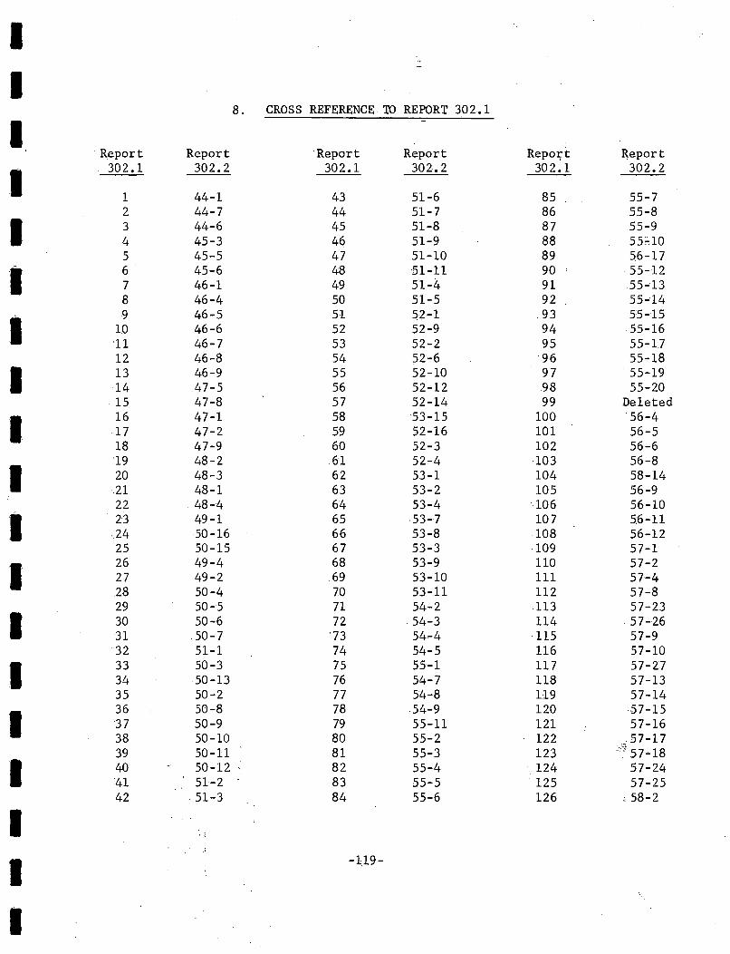
I..,-,
I8. CROS S REFERENCE, 1D REPORT 302.1
IRepoI;'tReport Report Report Report Report
I302.1 302.2 302.1 302.2 302~1 302.2
1 44-1 43 51-6 85 55-72 44-7 44 51-7 86 55-8
I 3 44-6 45 51-8 87 55-94 45-3 46 51-9 88 55;:'105 45-5 47 51-10 89 56-17
I 6 45 .. 6 48 51-11 90 . 55-127 46-1 49 51-4 91 55-138 46-4 50 51-5 92 55-14
I9 46-5 51 52-1 93 55-15
10 46-6 52 52-9 94 55-16'11 46-7 53 52-2 95 55-1712 46-8 54 52-6 96 55-18
I 13 46-9 55 52-10 97 55-1914 47-5 56 52-'12 98 55-20
·15 47-8 57 52-14 99 Deleted
I16 47-1 58 53-'15 100 56-417 47-2 59 52-16 101 56-518 47-9 60 52-3 102 56-6'19 48-2 61 52 ..4 103 56-8
I 20 48-3 62 53-1 104 58-1421 48-1 63 53-2 105 56-922 ,48-4 64 53-4 106 56-10
I 23 49-1 65 53-7 107 5,6-11,24 50-16 66 53-8 108 56-1225 50-15 67 53-3 109 57-1
I26 49-4 68 53-9 110 57-227 49-2 69 53-10 111 57-428 50-4 70 53-11 112 57-829 50-5 71 54-2 113 57-23
I 30 50-6 72 54-3 114 57-2631 ,50-7 '73 54,..4 115 57-932 51-1 74 54-5 116 57-10
I 33 50-3 75 55-1 117 57-2734 50-13 76 54-7 118 57-1335 50-2 77 54-8 119 57-14
I36 50-8 78 54-9 120 57-1537 50-9 79 55-11 121 57-1638 50'-10 80 55-2 122 ",57-1739 50-11 81 55-3 123 :;':'57-'18
I 40 50-12 ' 82 55-4 124 57-2441 51-2 83 55-5 125 57-2542 51-3 84 55-6 126 , 58-2
II
-119-
I
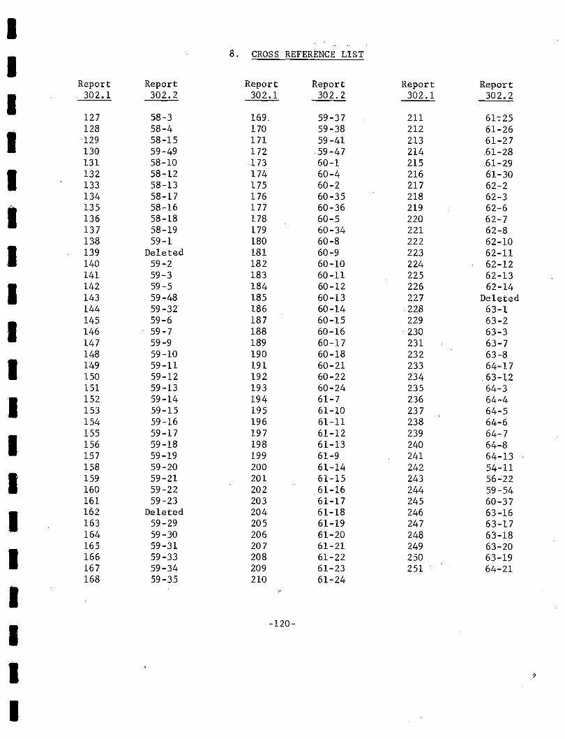
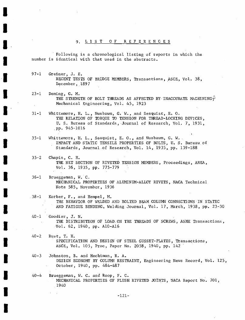
-121-
Following is a chronological listing of reports in which thenumber is identical with that used in the abstracts.
40-4 Brueggeman, W. C. and Roop, F. C.MECHANICAL PROPERTIES OF FLUSH RIVETED JOINTS, NACA Report No. 701,1940
23-1 Deming, G. M.THE STRENGTH OF BOLT THREADS AS AFFECTED BY INACCURATE MACHINING~
Mechanical Engineering, Vol. 45, 1923
REF ERE N C E S9. LIS T 0 F
38-1 Korber, F., and Hempel, M.THE BEHAVIOR OF WELDED AND BOLTED BEAM COLUMN CONNECTIONS IN STATICAND FATIGUE BENDING, Welding Journal, Vol. 17, March, 1938, pp. 23-30
36-1 Brueggeman, W. C.MECHANICAL PROPERTIES OF ALUMINUM-ALLOY RIVETS,NACA TechnicalNote 585, November, 1936
35-2 Chapin, C. H.THE NET SECTION OF RIVETED TENSION MEMBERS, Proceedings, AREA,Vol. 36, 1935, pp. 775-779
31-1 Whittemore, H. L., Nusbaum, G. W., and Seaquist,.E. O.THE RELATION OF TORQUE TO TENSION FOR THREAD-LOCKING DEVICES,U. S. Bureau of Standards, ·Journa1 of Research, Vol. 7, 1931,
,pp. 945-1016
35-1 Whittemore, H..L., .seaquist, E. 0., and Nusbaum, G. W.IMPACT AND STATIC TENSILE PROPERTIES OF BOLTS, U. S. Bureau. ofStandards, Journal of Research, Vol. 14, 1935, pp. 139-188
40-3 Johnston, B. and Hechtman, R. A.DESIGN ECONOMY BY COLUMN RESTRAINT, Engineering News Record, Vol. 125,October, 1940, pp. 484-487
40-2 Rust, T. H.SPECIFICATION AND DESIGN OF STEEL GUSSET-PLATES,Transactions,ASCE, Vol. 105, Proc, Paper No. 2058, 1940, pp. 142 .
40-1 Goodier, J. N.THE DISTRIBUTION OF LOAD.ON THE THREADS OF SCREWS, ASME Transactions,Vol. 62, 1940, pp. A10-A16
97-1 Greiner, J. E.RECENT TESTS OF BRIDGE MEMBERS, Transactions, ASCE, Vol. 38,December, .1897
IIIIIIIIIIIIIIIIIII
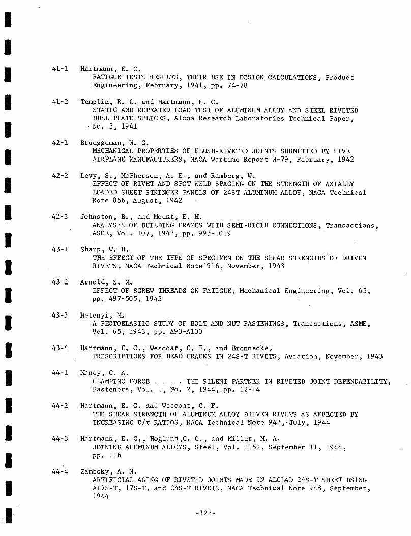
I,IIIIIIIIIIIIIIIII
.'1
41-1 Hartmann, E. C.FATIGUE TESTS RESULTS, THEIR USE IN DESIGN. CALCULATIONS, .ProductEngineering, February, 1941,pp. 74-78
41-2 Templin, R. L. and Hartmann, E. C.STATIC AND REPEATED LOAD TEST OF ALUMINUM ALLOY AND STEEL RIVETEDHULL PLATE SPLICES, Alcoa Research Laboratories Technical Paper,No.5, 1941
42-1 Brueggeman, W. C.MECHANICAL PROPERTIES OF FLUSH-RIVETED JOINTS SUBMITTED BY FIVEAIRPLANE MANUFACTURERS, NACA Wartime Report W-79, February, 1942
42-2 Levy, S., McPherson, A. E., and Re;tmberg, W.EFFECT OF RIVET AND SPOT WELD SPACING ON THE STRENGTH OF AXIALLYLOADED SHEET STRINGER PANELS OF 24ST ALUMINUM ALLOY, NACA TechnicalNote 856, August, 1942
42-3 Johnston, B., and Mount, E. H.ANALYSIS OF BUILDING FRAMES WITH SEMI-RIGID CONNECTIONS, Transactions,ASCE, Vol. 107, 1942, pp. 993-1019
43-1 Sharp, W. H.THE EFFECT OF THE TYPE OF SPECIMEN ON THE SHEAR STRENGTHS Olf DRIVENRIVETS, NACA Technical Note:'916, November, 1943
43-2 Arnold, S. M.EFFECT OF SCREW THREADS ON FATIGUE, Mechanical Engineering, Vol. 65,pp. 497-505, 1943
43-3 Hetenyi, M.A PHOTOELASTIC STUDY OF BOLT AND NUT FASTENINGS, Transactions, ASME,Vol. 65, 1943, pp. A93-AlOO
43-4 Hartmann, Eo C., Wescoat, .C. F., and Brennecke,PRESCRIPTIONS FOR HEAD CRACKS IN 24S-T RIVETS, Aviation, November, 1943
44-1 Maney, G. A.CLAMPING FORCE THE SILENT PARTNER IN RIVETED JOINT DEPENDABILITY,Fasteners, Vol. 1, No.2, 1944,pp. 12-14
44-2 Hartmann, E. C. and Wescoat, C. F.THE SHEAR STRENGTH OF ALUMINUM ALLOY DRIVEN RIVETS AS AFFECTED BYINCREASING Dlt RATIOS, NACA Technical Note 942, July, 1944
44-3 Hartmann, E. C., Hoglund,G. 0., and Miller, M. A.JOINING.ALUMINUM ALLOYS, Steel, Vol. 1151, September 11, 1944,pp. 116
44-4 Zamboky, A. N.ARTIFICIAL AGING OF RIVETED JOINTS MADE IN ALCLAD 24S-T SHEET USINGA17S-T, l7S-T, and 24S-T RIVETS, NACA Technical Note 948, September,1944
-122-
IIIIIIIIIIIIIIIIIII
44~5 Hartmann, E. C., Lyst, J. 00' and Andrews, H. J.FATIGUE TESTS OF RIVETED JOINTS: PROGRESS OF TESTS OF 17S-T AND53-T JOINTS, NACA Advance Restricted Report 4115, September, 1944
44-6 Wilson, W. M.DO RIVETS RETAIN THEIR INITIAL TENSION?, Civil Engineering, Vo1.14,No. 10, October, 1944, pp. 437-438
44-7 Stewart, W. C.WHAT TORQUE?, Fasteners, ,Vol. 1, No.4, 1944, pp. 8-10
44-8 Moisseiff, L. S., Hartmann, E. C., and Moore, R. L.RIVETED AND PIN-CONNECTED JOINTS OF STEEL AND ALUMINUM ALLOYS,Transactions, ASCE, Paper No. 2233:; Vol. 109, pp. 1359-1396
44-9 Wilson, W. M., Bruckner, W. Ho, Duberg, J. E., and Beede, M. C.FATIGUE STRENGTH OF FILLET-WELD AND PLUG-WELD CONNECTIONS INSTEEL STRUCTURAL MEMBERS, Bulletin No. 350, University 6f IllinoisEngineering Experiment Station, 1944
45-1 Hartmann, ,Eo C."Hog1und, G. 0., and Miller, M. A.METHODS OF JOINING ALUMINUM-ALLOY PRODUCTS, Transactions, ASME.,Vol. 67, No. 1, January,1945, ppo 1-21
45-2 Andrews, H. J., and Holt, M.FATIGUE TESTS ON·1/8 INCH ALUMINUM ALLOY RIVETS, NACA TechnicalNote, February, 1945
45-3 Ma~ey, G. A.BOLT STRESS MEASUREMENTS BY ELECTRICAL STRAIN GAGES, FasteI).e;rs,VoL 2, No.1, 1945,pp. 10-13
45.,.4 Moore ,R. L., and Hi 11, H. N.COMPARATIVE FATIGUE TESTS OF RIVETED JOINTS OF ALCLAD 24S-T,ALCLAD 24S-T81, ALCLAD 24S-RT, ALCLAD 24S-T86, AND ALCLAD 75S-TSHEET, NACA, Bu11etinNo. SF11, August, 1945
45-5 FastenersCOLD RIVETING GAINS ACCEPTANCE, Fasteners, Vol. 2, No. 3, r~45,
pp. 16-17
45-6 Crocker, S.BOLTING FOR PIPE FLANGES AND PRESSURE VESSELS, Fasteners, Part 1,in Vol. 2, No.4, 1945,pp. 4-7, and Part 2, ,in Vol. 3, No.1,1946',pp. 16-18
45-7 Wilson, W. M., and Oze11, Ao M.INVESTIGATION OF THE STRENGTH OF RIVETED JOINTS IN COPPER SHEETS,Bulletin No. 360, ,University of Illinois Engi~eering ExperimentStation, 1945 '
-123-
IIIIIIIIIIII'IIIIIII
46-1 Frankland, F. H.MORE EFFECTIVE USE OF RIVETS AND BOLTS, Engineering News Record,March 7, 1946, pp. 85-87
46-2 Hartmann, E. C.and Zamboky, A. N.COMPARISON OF STATIC STRENGTHS OF MACHINE COUNTERSUNK RIVETED JOINTSIN 24S-T, X7S5-T, AND ALCLAD 75S-T SHEET, NACA Technical Note 1036,May, 1946
46-3 Holt, M.FATIGUE FAILURES OF BOLTED, WELDED, AND RIVETED CONNECTIONS,Proceedings, ,Society of Experimental Stress AD,alysis, Vol. 3, No.2,pp. 131, 1946
46-4 Jackson, L. R., Wilson, W, M" Moore, H. F., and Grover, H. J.THE FATIGUE CHARACTERISTICS OF BOLTED LAP JOINTS OF 24S-T ALCLADSHEET MATERIALS, NACA, TN 1030, October, ,1946
46-5 Maney, G. A.REPEATED LOADS ON RIVET JOINTS, Fas teners, Vol, 3, No.2, 1946,pp. 14-15
46-6 Frankland, F, H.RIVETS AND BOLTS IN STRUCTURAL DESIGN, Fasteners, Vol, 3, No.3,1946, pp, 4~6,18
46-7 Maney, G, A.WHAT HAPPENS WHEN A BOLT IS TWISTED OifJF?, Fasteners, Vol. 3,No. 4,1946, pp. 12-16
46-8 Maney, G. A.PREDICTING BOLT TENSION,Fasteners, Vol. 3, No.5, 1946, pp. 16-18
46-9 Tate, M. B., and Rosenfeld, S. G.PRELIMINARY INVESTIGATION OF THE LOADS CARRIED BY INDIVIDUAL BOLTSIN BOLTED JOINTS, NACA, TN 1051, 1946
47-1 Millard, E. H.HALF A CENTURY OF COLD RIVETING, Fasteners, Vol. 4, No.1, 194v,pp. 7-9
47~2~ ,Hill, H. 0,DOES TORQUE WEAKEN BOLTS?,Fasteners, Vol. 4, No.1, 1947, pp. 10-12
47-3 Boiten, R. G.HEF GEDRAG VAN OP TREK BELASK VERBINDINGEN, BESTAANDE UIT STRIPPEN,DIE DOOR EEN BOUT OP EL KARR WORDEN GEKLEMD. (CONNECTIONS SUBJECTEDTO TENSION FORCES, CONSISTING OF LONG PLATES WHICH ARE CONNECTED BYBOLTS). De Ingenieur, Vol. 59, No.2, 1947, Ho1land,pp. 1-7
-124-
IIIIIIIIIIIIIIIIIII
47-4 Fefferman, R. L., and Langhaar ,R. L.INVESTIGATION OF 24S-T RIVETED TENSION JOINTS, Journal of the Aeronautical Sciences, Vol. 14 ,No.3, March, 1947 ,pp. 133-147
47-5 Pancoast, R. H.THE EFFECT ON BOLT SHEARING STRENGTH OF VARIOUS AMOUNTS OF TENSILESTRESS SIMULTANEOUSLY APPLIED, B. S. Thesis, FennCol1ege ,-cMay, ,1947
47-6 Badir,M.THE EFFECT OF RIVET PATTERN ON THE STRENGTH OF RIVETED JOINTS,
,M. S •. Thesis, l:Jt).iv.ersity of 111it.lOis, 1947"
47-7 Hendry, A. W.THE TESTING OF STRUCTURAL.CONNECTIONS, Engiqeering, Vol. 164,No. 4259, September 12, 1947, London,pp. 261-263
47-8 .Hech.tman, R. A., and Johnston, B. G•. RIVETED SEMI-RIGID BEAM-TO-COLUMN BPILDING. CONNECTIONS, .Cdmmi ttee on
Steel Structures Research, No. 206, AISC, November, 1947
47-9 Vogt, F..THE DISTRIBUTION OF LOADS ON'RIVETS CONNECTING A PLATE TO A BEAMuNDER TRANSVERSE LOADS, NACA, TN No •.1134, 1947
48-1 Kelly, J,. J.DESIGN FACTORS FOR THREADED FASTENERS, Fas teners,. Vol. 5" No.1,1948, pp~ 16-18
48 ... 2 Langdon,. Howard, H., and Fried, BernardFATIGUE OF GUSSETED JOINTS, NACA"TN 1514, September, 1948
48-3 Grinter, L. E.STRESSES IN GUSSET PLATES BY USE OF AN ANALOGOUS GRID (WITH APPENDIXON PROBLEM ANALYSIS by Marvin Mass) , Proceedings, .IABSE, Vol. 8,September, 1948 .
48 1 4 Lipson, C.DESIGNING BOLTS TO RESIST SHOCK LOADING, Fasteqers, Vol. 5, ,No.3,1948, pp. 4-6
48-5 .Hechtman, R. A.A STUDY OF THE EFFECTS OF HEATING AND DRIVING CONDITIONS ON HOT-DRIVENSTRUCTURAL STEEL RIVETS, Ph.D. Tqesis,. University of Illinois,September, 1948
48-6 Sopwith, D. G.THE DISTRIBUTION OF LOAD IN SCREW THREADS, Proceedings, I~stitution
of Mechanical Engineers, VoL 159, London,pp. 373-383, 1948
48-7 . Hartmann, E•.C., Miller, .M. A., and Stroup, p" T.JOINING ALUMINUM ALLOYS,. National Metals Handbook; 1948, pp. 777-786
-125-
IIIIIIIIIIIIIIIIIII
48-8
48-9
49-1
49-2
49-3
49-4
49-5
49-6
49-7
49-8
49-9
49-10
Richart, F. E. .A PROCEDURE FOR EVALUATING C~TIVE DAMAGE IN F~~m.QUE~ Ph.D.Dissertation, University of Illinois, 1948
Randall, P. N.FACTORS INFLUENCING THE STRENGTH AND DUCTILI1Y OF SLOTTED TENSILESPECIMENS OF STRUCTURAL STEEL PLATE, Ph.D. Dissertation, University ofIllinois, 1948
Pickel, W. F.TIGHTENING CHAR.i\CTERISTICS OF NUT AND STUD ASSEMBLIES, ProductEngineering, January, 1949
Kovac,J. J.PRELOADING INTERNAL WRENCHING BOLTS, Fasteners, Vol. 6, No.2,1949, pp. 10-12
Ros, M. and d~~adine, G.STATIC AND'-FATIGUE TESTS WITH DIFFERENT 1YPES OF COVER STRAPS WELDEDON AND MACHINED FROM THE SOLID STEEL MATERIAL AND ALSO WITH LAPJOINTS, Bericht Nr. 168, EMPA, Zurich, 194~
Hechtman, R. A.CONDITIONS AFFECTING THE SLIP OF STRUCTURAL STEEL BOLTED JOINTS,The Trend in Engineering, University of Washington, Vol. 1, No.4,October 1949 ,pp. 12-18
Cayci, .M. A.FATIGUE STRENGTH OF RIVETED JOINTS,M. S. Thesis, University of.Illinois, 1949
Wi1son,W. M., and Munse, W. H. .THE FATIGUE STRENGTH OF VARIOUS' DETAILS USED FOR THE REPAIR OFBRIDGE MEMBERS, Bulletin No. 382, University of Illinois EngineeringExperiment Station, 1949
Lenzen, K. H.BOLTED JOINTS UNDER FATIGUE LOADING, Fasteners, Vol. 6,No. 1, 1949,pp. 6-9 (See Abstract 50-16)
Pickel, W. F.TIGHTENING CHARACTERISTICS OF NUT AND STUD ASSEMBLIES, Fasteners,Vol. 6, No.1, 1949, pp. 10-13 (S~e Abstract 49-1)
Lenzen, K. H.THE EFFECT OF VARIOUS FASTENER ON THE FAFIGUE STRENGTH OF ASTRUCTURAL JOINT, Bulletin 480, AREA, June-July, 1949 (SeeAbstract 50-16)
RCRBSJPROGRESS REPORT OF RESEARCH COUNCIL ON RIVETED AND BOLTED STRUCTURAL JOINTS, Bulletin 482, AREA, September-October, 1949 (SeeAbs trac t 50 -13)
-126-
IIIIIIIIIIIIIIIIIII
.49-llWy1y, L. T., Scott, M. B., McCammon, L. B., and Lindner, C.,W.A STUDY OF THE BEHAVIOR OF FLOOR BEAM HANGARS, Bulletin 482,AREA, September-October, 1949 (See Abstract 50-15)
50-1Ho1t, M.'RESULTS OF SHEAR FATIGUE TESTS OF JOINTS WITH 3/16 INCH DIAMETER24S-T31 RIVETS IN 0~064 INCH THICK ALCLAD SHEET, NACA TechnicalNote 2012, February, 1950
50-2 Milliken, M. P., HOW TIGHT IS TOO TIGHT?, Fastell,ers, Vol. .6, No. 1,1950, pp. 14-17
50-3 AREA Committee on Iron.and Steel StructuresUSE OF HIGH STRENGTH STRUCTURAL BOLTS IN STEEL RAILWAY BRIDGES,Proceedings ,AREA, Vol. 51, March, 1950, pp. 506-540
50-4 Wy1y, L. T.SYMPOSIUM ON HIGH-STRENGTH BOLTS, Part I, Proceedings, AISC,April 12, 1950, pp. 22-27
50 - 5' Rub1e, E. J.SYMPOSIUM ON HIGH-STRENGTH BOLTS, Part II, Proceedings, AISG,April 12 , 1950 ,pp. 27-31
50-6 Stewart, W. C.SYMPOSIUM ON HIGH-STRENGTH BOLTS, Part III, .Proceedings, AISC,April 12, 195.0, pp. 31-36
50-7 Munse,W. H., Schutz, F. W., Jr., and Cox, H. L.STATIC .AND FATIGUE TESTS OF BOLTED STRUCTURAL LAP 'JOINTS,SRS No.3, Departmen,t of Civil Engineering, University of Illinois,Urbana, July, 1950
50-8 Harvey, C. L.HIGH STRENGTH STEEL BOLTS, Fasteners, Vol. 6, No.3, 1950,pp. 10-12
50-9 Pinke1, .R.H.DETERMINING BOLT LOAD ELONGATION CURVES, Fas teners, Vol. 6,
,No.4, 1950, pp. 8-9
50-10 Merritt, F. S.UN SECRETARIAT USED UNUSUALLY LARGE RIVETS, Fasteners, Vol. 6,No.4, .1950, pp. 12.,.14
50-11 Wy1y, L. T., and Carter"J. W.STRESSES NEAR BOLT AND RIVET HOLES, Fasteners, Vol. 6, ,No.4,1950, pp. 15-17
50-12 Lappo" T.EXTRA FLANGE RIVETS FOR WEB SPLICE EASILY COMPUTED, Civil Engineering.,Vol. 20, 1950, p. 786
-127-
IIIIIIIIIIIIIIIIIII
50 -13 RCRBS JPROGRESS REPORT OF RESEARCH COUNCIL ON RIVETED AND BOL,TED STRUCTURALJOINTS , Proceedings, AREA, Vol. 51, 1950 ,pp. 74-86
50-14 AREA Committee on Iron and Steel StructuresSTRESS DISTRIBUTION IN BRIDGE FRAMES-FLOORBEAM HANGERS, Proceedings,AREA, Vol. 5~, 1950, pp. 470-503
50-15 Wy1y, L., T., Scott, M. B.• ,McCammon, L. B., ,and Lindner,C. W.A STUDY OF THE BEHAVIOR OF FLOORBEAM HANGERS, Proceedings, AREA,Vol. 51, 1950, pp. 51-73
50-16 Lenzen, K. H.THE EFFECT OF VARIOUS FASTENERS ON THE FATIGUE STRENGTH OF ASTRUCTURALJOINT,Proceedings, AREA, Vol. 51,1950, pp. 1-28
50-17 Dolan, T. J. andMcC1ow,J. H.THE INFLUENCE OF BOLT TENSION AND ECCENTRIC 'TENSILE LOADS ON THEBEHAVIOR OF A BOLTED JOINT ,Proceedings ,Societyfor ExperimentalStress Analysis, Vol. 8,No. 1, 1950, pp. 29-43
5,0-18 Navy ,Department, BOLT DESIGNS UNDER SHOCK LOADING , NRLProb1em No. 38F03-20T,
Naval Research Laboratory, Washington, D.C., February, 1950
50-19 Chu, K.A STUDY OF DESIGN SPECIFICATIONS FOR STEEL BRIDGES"Ph.D.Dissertation, University of Illinois, 1950
50-20 Wilson,W.,M."Munse"W. H., ,and Cayci, M. A.THE EFFECT OF THE RIVET PATTERN ON STATIC STRENGTH OF RIVETEDJOINT CONNECTING PLATES, -Department of Civil Engineering,University of Illinois, Progress Report ProJect II,January,1950. (See Abstract 52-10) I,
50-21 Lind, H. H.,COOPERATIVE RESEARCH, Fasteners, Vol. 6, No.3, 1950, pp.8-9,(See Abstract 5P-13)
50-22 Ruble, ,E.J., USE OF HIGH STRENGTH STRUCTURAL BOLTS IN, STEEL RAILWAY' BRIDGES,,Fasteners, Vol. 6,No. 4, 1950, pp~ 3-5 (See Abstract 50-3)
51-1 Wilson, W. ,M.HIGH-STRENGTH BOLTS AS A MEANS OF FABRICATING STEEL STRUCTURES,Proceedings, Highwa)':,;Re~earch Board, 1951 ,pp. 136-143
51-2 Wright, D. T., and Munse, W. H.CALIBRATION TESTS OF HIGH STRENGTH BOLTS, Department of Civil~ngineering, University of Illinois, SRS No.9, January, 1951
-128-
IIIIIIIIIIIIIIIIIII
51-3 Becker ,We K., Sinnamon, G. K., and Munse,W. H.THE EFFECT OF BEARING PRESSURE ON THE STATIC STRENGTH OF RIVETEDJOINTS, Department of Civil Engineering, University of Illinois,SRS No.8, January, 1951.
51-4 Hartmann, E. C., Holt, M., and Eaton, 1. D.STATIC AND FATIGUE STRENGTHS OF HIGH-STRENGTH ALUMINUM ALLOYBOLTED JOINTS, NACA TN 2276, Washington, February, .1951
51-5 FastenersMORE THAN A MILLION POUNDS OF FASTENERS" Fasteners, Vol. 7,No.1, 1951, pp. 5-6
51-6 Young, D. Ro, and Hechtman, R. A.SLIP OF STRUCTURAL STEEL DOUBLE-LAP JOINTS ASSEMBLED WITH HIGH
. STRENGTH BOLTS, The Trend in Engineering, ,Part I in April 1951,pp. 24-27, and Part II in July 1951, pp. 23-26
51-7 Higgins, T. R.BOLTED JOINTS FOUND BETTER UNDER FATIGUE, ,EngiqeeringNewsRecord, Vol. 147, August 2, 1951, pp. 35-36
51-8 Redshaw, So C.THE DESIGN CHARACTERISTICS OF ALUMINUM RIVETED JOINTS, Symposiumon WeiLding and Riveting Larger Aluminum Structures, London,November, 1951, pp. 155-1750
51-9 Bailey, J o C.THE PROPERTIES AND DRIVING OF LARGE ALUMINUM ALLOY RIVETS,Symposium on Welding and Riveting Larger Aluminum Structures,London, November, 1951, pp. 133-1540
51-10 Delaney, To J.COLD RIVETING USED IN FIRST ALL-ALUMINUM HIGHWAY BRIDGE,Fasteners, Vol. 7,No.2, 195,1, pp. 5-6
51-11 Ruble" E. J.STRUCTURAL DESIGNERS ACCEPT HIGH STRENGTH BOLTS, Fasteqers,Vol. 7, No. 2,1951, ppo 7-10
51-12 Eaton, I. Do, and Holt" M., FLEXURAL-, FATIGUE STRENGTHS OF RIVETED BOX-BEAMS ALCLAD 14S-T6,
ALCLAD 75S-T6, ,AND VARIOUS TEMPERS OF ALCLAD 24S, NACA TechnicalNote 2452, November, 1951
51-13 Stang" Ao H.THE TENSILE FORCES IN TIGHTENED BOLTS, Product Engineering,February, 1951
51-14 Carter, J. W.STRESS CONCENTRATION IN BUILT-UP STRUCTURAL MEMBERS AND ITS EFFECTON THEIR ENDURANCE LIMIT, PhoD. Dissertation, ,Purdue University,1951 (See Abstract 52-19)
-129-
IIIIIIIIIIIIIIIIIII
51-15 Becker, W. K.THE EFFECT OF BEARING PRESSURE ON THE STATIC STRENGTH OF RIVETEDJOINTS, M. S. Thesis, University of Illinois, 1951 (See Abstract51-3)
52-1 Massard, J. M., Sinnamon, G. K., ,and Munse, W. H.THE EFFECT OF BEARING PRESSURE ON THE STATIC STRENGTH OF RIVETEDJOINTS, Department of Civil Engineering, University of Illinois;SRS No. 21, January, 1952
52-2 Wright, D. T., and Munse, W. H.STATIC TESTS OF BOLTED AND RIVETED JOINTS, Department of CivilEngineering, University of Illinois, SRS No. 20, January, 1952
52-3 Fe1dhausen, G. J.,Jr.DO SEMI-RIGID CONNECTIONS PROVE ECONOMICAL?, .Fasteners, Vol. 8,No.1, 1952, pp. 7-10
52-4 FastenersBOLTS SPEED ERECTION, Fasteners, Vol. 8,No. 1, 1952, pp. 12-13
52-5 Baron, Fo, and Larson, E. Wo, Jr.THE EFFECT OF CERTAIN RIVET PATTERNS ON THE FATIGUE AND STATIC
. STRENGTHS OF JOINTS, .Part I, Department of Civil Engineering,Northwestern University, February 1, 1952
52-6 Whitmore, R. E.EXPERIMENTAL INVESTIGATION OF STRESSES IN GUSSET PLATES,Bulletin Noo 16, Engineering Experiment Statio~, Universityof Tennessee, Knoxville, May, 1962
52-7 Bai1ey,J. C., and Brace, A. W.STRENGTH TESTS ON DRIVEN LARGE DIAMETER ALUMINUM RIVETS, TheAluminum Development Association, Research Report No. 13, May,1952, London
52-8 . Davey, J. S.STRENGTH OF BOLTED ASSEMBLIES, Tool Engineer, May, 1952
52-9 Fisher, W. Ao P., Cross, R. H., and Norris, G. M.PRE-TENSIONING FOR PREVENT~NG FATIGUE FAILURE IN BOLTS, AircraftEngineering, England, Vol. XXIV, No. 280, June, 1952, pp. 160-163
52-10 Wilson, W. Mo, Munse, W. Ho, and Cayci, M. AoA.STUDY OF THE PRACTICAL EFFICIENGY UNDER STATIC LOADING OFRIVETED JOINTS CONNECTING PLATES, Bulletin No. 402, EngineeringExperiment Station, Universi ty of Illinois, .July , 1952 '
52-11 Brow~, A. A.ANALYSIS OF ANCHOR BOLTS AND CONCRETE'~:PIERS FOR LARGE STILLSAND KETTLES, Civil Engineering, Vol. 22, July, 1952, pp. 491-492
-130-
IIIIIIIIIIIIIIIIIIII
52-12 Schutz, F. W., and Newmark, N. M.THE EFFICIENCY OF RIVETED STRUCTURAL JOINTS, Department ofCivil Engineering, University of Illinois ,SRS No. 30,September, 1952
52-13 Higgins ,T. R., and Ruble, E. J.HIGH-STRENGTH BOLTS - A NEW CONCEPT IN STRUCTURAL CONNECTIONS,Civil Engineering, Vol. 22, No. 9, September, 1952, pp. 760-763
52-14 Stewart, W. C.STRUCTURAL JOINTS WITH HIGH-STRENGTH BOLTS, Proceedings, TheSecond Illinois Structural Engineering Conference, Universityof Illinois, Urbana, November, 1952
52-15 Kreis1e, L. F., and Oliphiht,J. B.BOLT ELONGATIONS AND LOADS, Transactions, ASME, Vo1. 74,1952, pp. 38
52-16 Higgins, T. R., and Munse,W. H.HOW MUCH .COMBINED STRESS CAN A RIVET TAKE?;;, Engineering NewsRecord, December 4, 1952, Vol. 149, No. 23, pp. 40-42
52-17 Howard, D. M., and Smith, F. C.FATIGUE AND STATIC TESTS OF FLUSH RIVETED JOINTS, NACATechnical Note 2709, 1952
52-18 Scott,M. B., and Cox,J. W.A FURTHER STUDY OF THE BEHAVIOR OF FLOOR BEAM RANGERS,Proceedings, AREA, Vol. 53, 1952, pp. 35-64
52-19 Carter, J. W.STRESS CONCENTRATIONS IN BUILT-UP STRUCTlJRAL MEMBERS, Proceedings, AREA, Vol. 53,1952, pp. 1-34
52-20 Schutz, F. W.EFFECTIVE NET SECTION OF RIVETED JOINTS, Proceedings, 2ndIllinois Structural Engineering Conference, November, 1952,pp. 54-62 (See Abstract 52-12)
52-21 Schutz, F. W.THE EFFICIENCY OF RIVETED STRUCTURAL JOINTS, Ph.D. Dissertation,Universi ty of Illinois, 1952 (See Abstract 52-12)
52-22 Wright, D. T.TESTS OF HIGH TENSILE BOLTED STRUCTURAL JOINTS, M•. S. Thesis,University of Illinois, 1952 (See Abstract 52-2).
52-23 Baron, F., and Larson, E. W.THE EFFECT OF GRIP ON THE FATIGUE STRENGTH OF RIVETED ANDBOLTED JOINTS ,Bulletin 503" AREA, 1952 (See Abstract 53-15)
-131-
IIIIIIIIIIIIIIIIIII
52-24 Chang, F.K., and Johnston, B. G.TORSION OF PLATE GIRDERS, Proceedings, ASCE, Sep. No. 125,April, 1952, (See Abstract 53-ll)
52-25 Cox ,H. L., STATIC STRENGTH OF RIVETS SUBJECTED TO:COMBINED TENSION AND
SHEAR,M. S. Thesis, Universi tyof Illinois, 1952 (SeeAbstract 56-12)
52- 26 Muns e, W. H., ,and Cox , H. L.THE STATIC STRENGTH OF RIVETS SUBJECTED TO COMBINED TENSION
. AND SHEAR, SRS No. 22, .Department of Civil Engineering,University of Illinois, January ~ . 1952 (See Abstrac t 56-12)
53",:1 Engineering News .RecordHERE'S A BETTER WAY 'TO DESIGN SPLICES, EngiqeeringNewsR~cord, Vol. 150,Part I,January 8,1953, pp. 41-42
53-2 Fuller ,James R., and Munse, W. H.LABORATORY TESTs OF STRUCTURAL· JOINTS WITH OVER-STRESSEDHIGH TENSILE STEEL BOLTS, Departmeqt of Civ;ilEngineering,University of Illinois, .SRS No. 44,_ January, 19~3 .
53-3 FastenersHIGH STRENGTH BOLTING, Fasteners, Vol. 9, No.1, Ohio, 1953,RP. 9-13
53-4 Francis, A. J.THE BEHAVIOR OF ALUMINUM ALLOY RIVETED JOINTS, ResearchReport No. 15, The Aluminum Development Association, London,March, 1953
53-5 Bergendoff ,R. C., and Munse" W. H.rim EFFECT OF BEARING PRESSURE ON THE STATIC STRENGTH OFRIVETED JOINTS ,SRS No. 55, Universi tyof I11i~ois, June,1953 -
53-6 Sossenheimer,H.ZUR VERWENDUNGHOCHFESTER SCHRAUBEN (ON THE APPLICATION OFHIGH-STRENGTH BOLTS), Der S.tah1bau, Vol. 22(1953), Heft 9,pp. 214-215
53-7 ResearchCouncilon.Riveted and Bolted Struct~ralJoints
NEW CONCEPTS IN STRUCTURAL JOINT DESIGN, Second Progress Reporton Research Council on ,Riveted and Bo1-ted Strqctura1 Joints,Distributed by the Engineering Foundation, December, .1953
53-8 ,AREA Comrrd.ttee on .Iron and Steel Structures,. ~ ,
USE OF 'HIGH-STRENGTH STRUCTURAL BOLTS IN STEEL RAILWAY BRIDGES,Proceed:i.ngs,AREA, Vol. 54,1953, pp •.929-940
-132-
IIIIIIIIIIIIIIIIIII
53-9 Baron, F.• , and Larson, E. W., Jr.PROPERTIES AND BEHAVIOR OF A HIGH-STRENGTH RIVET STEEL, Pro-ceedings, ASTM, Vol. 53, 1953, pp. 597-609 -
53-10 Baron, F., .and Larson, E. W., Jr.STATIC AND FATIGUE PROPERTIES OF CARBON, SILICON, .AND HIGHSTRENGTH LOW-ALLOY STEEL PLATES HAVING A HOLE, Proceedings,ASTM, Vol. 53, 1953, pp. 805-822
53-llChang, F. K., and Johnston, B. G.TORSION OF PLATE GIRDERS, Transactions, ASCE, Paper No. 2549,Vol. 118, 1953, pp. 337-382
53-12 Hy1er,W. S., and Grover, H•. J.THE TENSION-TENSION FATIGUE BEHAVIOR OF1/4-INCH ALLOY-STEELHUCK LOCKBOLTS, S-1205-4, Huck Manufacturing Company, .Detroit,Michigan,. December 18, 1953
53-13 Nelson, H. M.ANGLES INTENSION, SUMMARY OF A REPORT ON· TESTS CARRIED OUT FORTHE BRITISH CONSTRUCTIONAL STEELWORK ASSOCIATION, BCSA PublicationNo~ 7,London, 1953
53-14 COX~ J. W.EXPERIMENTAL AND ANALYTICAL STUDIES OF STRESS DISTRIBUTION INLABORATORY MODELS OF FLOORBEAM HANGER FRAMES, Proceedings,AREA, Vol. 54, 1953,pp. 65-132
53-15 Baron, F., and Larson, E. W., ,Jr.THE EFFECT OF GRIP ON THE FATIGUE STRENGTH OF RIVETED AND BOLTEDJOINTS,Proceedings, AREA, Vol. 54, 1953
53-16 Stewart, W. C.PROPERTIES OF PRELOADED STEEL BOLTS, .Product Engineering, November,1953
53-17 Bergendoff, R. C.THE EFFECT OF BEARING PRESSURE ON .THE STATIC STRENG~H OF RIVETEDJOINTS, M. S. Thesis, University of Illinois, 1953 (SeeAbstract 53-5)
53-18 Brady,~. G~, and Drucker, D.C.AN EXPERIMENTAL INVESTIGATION· AND LIMIT ANALYSIS OF NET AREAIN TENSION, Proceedings, ASCE, Vol. 7.9, Sep. No. 296, October,1953 (See Abstract 55-12)
53-19 Stallmeyer, J. E.THE EFFECT OF STRESS HISTORY ON CUMULATIVE DAMAGE IN FATIGUE,Ph.D. Dissertation, University of Illinois, 1953
-133-
~ ..'
IIIIIIIIIIIIIIIIIII
54-1 Baron, F., and Kenworthy, K. J.THE EFFECT OF CERTAIN RIVET PATTERNS ON THE FATIGUE AND STATICSTRENGTH OF JOINTS, Part II, Department of Civil Engiqeering,Northwestern University, February 1, 1954
54-2 Laub, W. H., and Phillips, J. R.THE EFFECT OF FASTENER MATERIAL AND FASTENER TENSION ON THEALLOWABLE BEARING STRESSES OF STRUCTURAL JOINTS, FritaLaboratory Report 243.2, Lehigh University, Bethlehem,Pennsylvania, June, ,1954
54-3 Schenker, L., Salmon, G. G., and ~ohnston, B. G.STRUCTURAL STEEL CONNECTIONS, University of Michigan, AFSWPReport No. 352, Project 2065-1-F, June, 1954
54-4 Hartmann, E. G., Ho1 t, M., and Eaton, 1. D.ADDITIONAL STATIC AND FATIGUE TESTS OF HIGH-STRENGTH ALUMINUMALLOY BOLTED JOINTS, NACA TN 3269, Washington, D. C., July, 1954
54-5 Leahey, T. F., and Munse, W. H.STATIC AND FATIGUE TESTS OF RIVETS AND HIGH-STRENGTH BOLTS INDIRECT TENSION, Department of Civil Engineering, University ofIllinois, SRS No. 80, July, 1954
54-6 Nicholson, H. H.A MILLION AND A HALF HIGH-STRENGTH BOLTS SPEED UP STEELERECTION, Civil Engineering, Vol. 24, No.8, August, 1954,pp. 521-524
54-7 VastenersRESEARCH COUNCIL ANNOUNCES NEW SPECIFICATIONS FOR HIGH STRENGTHBOLTS, Fasteners, Vol. 9, No.3, Ohio, 1954,pp. 10-12
54-8 Delaney, T. J.RIVETING CANADA 's ALUMINUM MINESWEEPERS, Fasteners, Vol. 9,No.4, Industrial Fasteners Institute, Cleveland, Ohio, 1954,pp. 6-7
54~9 Ringer, A. G.PRINCIPLES AND USES OF IMPACT WRENCHING, Fasteners, Vol. 10,No.3, 1954, pp~ 3-5
54-10 Ernst, E.DIE ERSTE EISENBAHNBRUCKE DER DEUTSCHEN BUNDESBAHN MIT VORGESPANNTEN,HOCHFESTEN SCHRABUEN A/S VERBINDUNGSMITTEL (THE FIRST RAILROAD BRIDGEWITH PRESTRESSED, HIGH~STRENGTH BOLTS AS CONNECTIONS MEANS}, DerStah1bau, Vol. 33, (1954), Heft 10, pp. 225-228
54-11 Steinhardt, 0., and Mohler, K.VERSUCHE ZUR ANWENDUNG VORGE SPANNTER SCHRAUBEN 1M STAHLBAU, 1. TElL(TESTS ON THE APPLICATION OF HIGH-STRENGTH BOLTS IN STEEL CONSTRUCTION,PART I), Berichte des Deutschen Aussachusses fur Stah1bau, Stah1bauVer1ags, GmbH, Cologne, 1954 Heft. Nr. 18
-134-
IIIIIIIIIIIIIIIIIII
54-12 Templin, R. L.FATIGUE OF ALUMINUM, Proceed~ngs, ASTM, Vol. 54, pp. 641, 1954
54-13 Fuller, J. R., Leahey, T. F., and Munse, W. H.STATIC TENSILE TES TS OF I -SECTION CONNECTIONS, SRS No. 68,Department of Civil Engineering, University of Illinois,January, 1954 (See Abstract 55-4) .
54-14 Stewart, w. C.THE WORK OF THE RESEARCH COUNCIL ON RIVETED AND BOLTED JOINTS,Proceedings, ASCE, Vol. 80, Sep. No. 440" May, .1954 (SeeAbstract 55-13)
·54-15 Munse, W. H., Wright, D. T., and Newmark, N. M.LABORATORY· TESTS OF HIGH TENSILE BOLTED STRUCTURAL JOINTS,Proceedings, ASCE, Vol. 80, Sep. No. 441, May, 1954 (SeeAbstract 55-14)
54-16 Leahey, T. F.STATIC AND FATIGUE TESTS OF RIVETS AND HIGH-STRENGTH BOLTS INDIRECT TENSION,M. S•. Thesis, University of Illinois, 1954.(See Abstract 54-5)
54-17 Beam, W. S.EFFECTS OF REPEATED LOADINGS ON STRUCTURAL CONNECTIONS WITHHIGH STRENGTH BOLTS, .M. S. 'Thesis, University of Illinois,1954 (See Abstract 55-11) .
54-18 Howard, L. L.A STATISTICAL STUDY OF THE TENSION DEVELOPED IN HIGH STRENGTHSTRUCTURAL BOLTS TIGHTENED WITH PNEUMATIC IMPACT WRENCHES,
., Department of Civil Engineering, University of Missouri, 1954(See Abstract 55-5)
54-19 Baron, F., and Larson, E. W.,Jr.COMPARATIVE BEHAVIOR OF BOLTED AND RIVETED JOINTS, Proceedings,ASCE, Vol. 80, Sep. No. 470, August, 1954 (See Abstract 55-:-17)
54-20 Hechtman, R. A., Young, D. R., Chin, A. G~, and Sa:vikko, E. R.SLIP OF JOINTS UNDER STATIC LOADS, Proceedings, ASCE, Vol. 80,Sep. No. 484, August, 1954 (See Abstract 55-18)
54-21 Carter, J. W., ,Lenzen, K., H., and Wy1y, L. T.FATIGUE IN RIVETED AND BOLTED SINGLE LAP JOINTS, Proceedings,ASCE, Sep. No. 469, August, 1954 (See Abstract 55-19)
54-22 Higgins, T. R., and Ruble, E. J.STRUCTURAL APPLICATION OF HIGH STRENGTH BOLTS, Proceedings,ASCE, Vol. 80, Sep. No. 485, September, 1954 (See Abstract 55-20)
-135-
IIIIIIIIIIIIIIIIIII
54-23 Carter,.J. W., McCalley, J. C., and Wyly, L. T.COMPARATIVE TEST OF A STRUCTURAL JOINT CONNECTED WITH HIGHSTRENGTH BOLTS AND A STRUCTURAL JOINT CONNECTED WITH RIVETS ;AND HIGH-STRENGTH BOLTS', Bulletin 517, AREA, SeptemberOctober, 1954 (See Abstract 55-1)
55-1 Carter, J. W., McCalley, J. C., and Wyly, L. T.COMPARATIVE TEST OF A STRUCTURAL JOINT CONNECTED WITH HIGH-
. STRENGTH BOLTS AND A STRUCTURAL JOINT CONNECTED WITH RIVETS ANDHIGH-STRENGTH BOLTS, Proceedings, AREA, Vol. 56, 1955,pp. 217-268
55-2 Baron , F., Larson, E. W., Jr., and Kenworthy, K. J.THE· EFFECT OF CERTAIN RIVET PATTERNS ON THE FATIGUE ANDSTATIC STRENGTH OF JOINTS,Published by the Research Councilon Riveted and Bolted Structural Joints, Distributed by theEngineering Foundation, February, 1955
55-3 Hechtman, R. A., Flint, T. R., and Koepsell, P. L.FIFTH PROGRESS REPORT ON SLIP OF STRUCTURAL STEEL DOUBLE-LAP JOINTS ASSEMBLED WITH HIGH-TENSILE STEEL BOLTS,Department of Civil Engineering, University of Washington, Seattly,February, 1955
55-4 Fuller, J. R., Leahey, T. F., and Munse, W•. H.A STUDY OF THE BEHAVIOR OF LARGE I~SECTION CONNECTIONS,Proceedings, ASCE, Vol. 81, Sep. No. 659, April, 1955
55-5 Pauw, A., and Howard, L. L.TENSION CONTROL FOR HIGH-STRENGTH STRUCTURAL BOLTS, Proceedings,AISC, April, 1955, pp. 13-21
55-6 Ruble, E. J.TURN-OF-THE-NUTMETHOD, Proceedings, Ais~, April, 1955,pp. 21-26
55-7 Drew, F. P.TIGHTENING HIGH STRENGTH BOLTS, Proceedings, ASCE, Vol. 81,Paper No .786 , August, 1955
55...,8 Pauw, A.DISCUSSION OF (IITIGHTENING HIGH-STRENGTH BOLTS II by F. P. Drew),Proceedings, ASCE, Vol. 81 ,Paper No. 381 ,November, 1955
55-9 Mitchell, W. D., and Rosenthal, D.INFLUENCE OF THE ELASTIC CONSTANTS ON THE PARTITION OF LOADBETWEEN RIVETS, Proceedings of the Society for ExperimentalStress Analysis, Vol. 7, No.2, 1955,. pp. 17-26
55-10 AREA Committee on Iron and Steel StructuresUSE OF HIGH STRENGTH STRUCTURAL: BOLTS IN STEEL RAILWAY BRIDGES,Proceedings, AREA, Vol. 56, 1955, pp. 592-634
-136-
IIIIIIIIII,II,
II'I,
IIII
55-11 Beam, W. S., ar.d Munse, W. H.EFFECTS OF REPEATED LOADINGS ON STRUCTURAL CONNECTIONS WITHHIGH-STRENGTH BOLTS, Department of Civil Engineering, Universityof Illinois, SRS No. 91, January, 1955
55-12 Brady, W. G., and Drucker, D. C,INVESTIGATION AND LIMIT ANALYSIS OF NET AREA IN TENSION,Transactions, ASCE, Vol, 120, 1955, pp. 1133-1164
55-13 Stewart, W. C.HISTORY OF THE USE OF HIGH-STRENGTH BOLTS, Transactions,ASCE, Vol. 120, Paper No. 2778, 1955, pp. 1296-1298
55-14 Munse, W. H., Wright, Do T., and Newmark, N. M.LABORATORY TESTS OF BOLTED JOINTS, Transactions, ASCE, Vol. 120,Paper No. 2778, 1955, pp. 1299-1318
55-15 Francis, Ao J.DISCUSSION ON ("LABORATORY TESTS OF BOLTED JOINTS" by Munse,Wright, and Newmark), Transactions, ASCE, Vol. 120,1955,pp. 1319-1320
55-16 Munse, Wo Ho, Wright, D. To, and Newmark, NoM.COMMENTS ON THE DISCUSSIONS ON ("LABORATORY TESTS OF BOLTEDJOINTS"), Transactions, ASCE, Vol. 120, 1955, pp. 1320-1321
55-17 Baron, Fo, and Larson, Eo W., Jr.COMPARISON OF BOLTED AND RIVETED JOINTS, Transactions, ASCE,Vol. 120, Paper Noo 2778, 1955, pp. 1322-1334
55-18 Hechtman, Ro Ao, Young, Do R., Chin, A. G., and Savikko, E. R.SLIP OF JOINTS UNDER STATIC LOADS:,' Transactions, ASCE, Vol. 120,Paper No. 2778, 1955, pp. 1335-1352
55-19 Carter, J. W., Lenzen, Ko H., and Wy1y, Lo T.FATIGUE IN RIVETED AND BOLTED SINGLE LAP JOINTS, Transactions,ASCE, Vol. 120, ,1955, ppo 1353-1383
55-20 Higgins, To R';, Ruble, E. J.STRUCTURAL USES OF HIGH STRENGTH BOLTS, Transactions, ASCE,Vol. 120, 1955, ppo 1389-1398
55-21 Schmid, W.NEUERE AMERIKANISCHE VERSUCHE MIT HOCHFESTEN SCHRAUBEN(NEW AMERICAN TESTS ON HIGH-STRENG~H BOLTS), Der Bauingerieur30 (1955), Heft 8, ppo 302-307
55-22 Schmid, W.HOCHFESTE SCHRAUBEN IN DER AMERlKANISCHEN STAHLBAUPRAXIS(HIGH-STRENGTH BOLTS IN AMERICAN STEEL CONSTRUCTION), DerBauingerieur 30 (1955), Heft 12, pp. 436-439
-137-
II,I
IIIIIIIIIIII.1III
55-23 Schmid, W.ZURVERSUCHE MIT GROSSEN TRAGERANSCHLUSSEN (TE~SILE TESTS ONLARGE BEAM CONNECTIONS), Der Bauingenieur 30 (1955), Heft,L2,pp. 439-441
55-24 .Sippell, K.W.DASFLA~TRAHLEN (FLAME TREATMENT), Metalloberflache, Teil A,Vol. 9 (1955), Heft 10, pp. l47(a) - 162(A)
55-25 Wiegand, H., Sch~ar, K., and Nieth, F.BEITRAG ZUM ENTZUNDERN VON WALZMATERIAL DURCH FLAMMSTRAHLEN(ON THE FLAME TREATMENT OF ROLLED MATERIALS) , ,Metalloberflache,Teil A, Vol. 9 (1955), Heft 10, pp. l62(A) - l73(A)
55-26 Nieth, F.DIE BESCHAFFENHEIT DER STAHLOBERFLACHE BEl ANWENDUNG .:VESCHIEDENER ENTROSTUNGS-UND ENTZUNDERUNGSVERFAHREN (TaECONDITION OF THE STEEL SURFACE ~FTER THE APPLICATION OF THEVARIOUS METHODS OF SURFACE TREATMENT), Metalloberflache, Teil A,Vol. 9 (1955), Heft 10, pp. l74(A) - l78(A)
55-27 Berg, S., and Sippell, K. W.EINFLUSS DES FLAMMSTRAHLENS AUF DIE FESTIGKEIT VON BAUTEILEN(THE INFLUENCE OF FLAME TREATMENT ON THE STRENGTH OF STRUCTURALMEMBERS), Metalloberflache, Teil A., Vol. 9 (1955), Heft 10,pp. l79(A) - l85(A)
55-28 Ingenerf, W.HOCHFESTE,. VORGES PANNTE SCHRAUBEN FUR DEN STAHL- UND KRANBAU(HIGH-STRENGTH, PRESTRESSED BOLTS FOR STEEL AND CRANE CONSTRUCTTQN), Fordern und Heben,1955, Heft 6,pp. 372-376
55-29 Kellermann, R., and Klein, H. -GHUNTERSUCHUNGEN UBER DEN EINFLUSS DER REIBUNG AUF VORSPANNUNGUND ANZUGSMOMENT VON SCHRAUBENVERBINDUNGEN, Kons truk:t,ion,Vol. 7, No.2, 1955, pp. 54-68 1",11'
55-30 Hancke, A.ANZUGSMOMENT, REIBUNGSWERT UND VORSPANNKRAF'T-!; BEl HOCHFESTENSCHRAUBEN (TIGHTENING MOMENT, COEFFICIENT OF FRICTION, ANDPRESTRESSING FORCE FOR HIGH-STRENGTH BOLTS), Draht, Vol. 6(1955), No.2, pp. 39-42, and No.3, pp. ~6-93
55-31 Sossenheimer, H.ZUR ANWENDUNG VON HOCHFESTEN SCHRAUBEN (ON THE APPLICATION OFHIGH-STRENGTH BOLTS), Der Stahlbau 24, 1955, Heft 1, pp. 11-16
55-32 Steinhardt, O.VORGESPANNTE SCHRAUBEN 1M STAHLBAU. (PRESTRESSED BOLTS IN STEELCONSTRUCTION), VDI-Zeitschrift 97 (1955) ,po 701-708
-138-
IIIIIIIIIIIIIIIIIII
55-33 Hebrant, F., and Demol, L.TENSILE TEST ON RIVETED CONNECTIONS OF ROLLED SECTIONS MADEOF STEELA37, Acier Stahl Steel, April, 1955, pp. 178-184
55-34 Mordfin, L.CREEP AND CREEP RUPTURE CHARACTERISTICS OF SOME RIVETED ANDSPOT-WELDED LAP JOINTS OF AIRCRAFT MATERIAL, NACA TechnicalNote 3412, June, 1955
55-35 Boomsma, M.LOOSENING AND FATIGUE STRENGTH OF BOLTED JOINTS, The Engineer,Vol. 200, p.284, London, August 26, 1955
55-36 Sandberg, C. H.INVESTIGATION OF FLOORBEAM HANGERS IN RAILROAD TRUSSES,Journal of the Structural Division, ASCE, Vol. 81, ProceedingsPaper No. 762,. August, 1955
55-37 Wilson, W. R.HIGH-TENSILE BOLTS ARE GAINING, Railway Track and Structures,September, 1955, pp. 43-45
55-38 Fuller, J. R.CUMULATIVE DAM\GE IN THE FATIGUE OF STRUCTURAL JOlNTS,Ph.D. Dissertation, University of Illinois,. 1955 (SeeAbs trac t 59 -49)
55-39 Munse, W. H.BOLTED CONNECTIONS RESEARCH, Proceedings, ASCE, Vol. 81,Sep. No. 650, March, 1955 (See Abstract 56-11)
55-40 Wyly, L. T., and Scott,.M. B.AN INVESTIGATION OF FATIGUE FAILURES IN STRUCTURAL MEMBERSOF ORE BRIDGES UNDER SERVICE LOADING, Bulletin 524, AREA,1955 (See Abstract 56-17)
55-41 Bell, M. H.HIGH-STRENGTH STEEL BOLTS IN STRUCTURAL PRACTICE, Proceedings,ASCE, Vol. 81, Sep. No. 651, March, 1951 (See Abstract 57-27)
56-1 Winter, G.TESTS ON BOLTED CONNECTIONS IN LIGHT GAGE STEEL, Journal offhe Structural Division, ASCE, Vol. 82, Proceedings Paper 920,February, 1956
56-2 Committee on Design in Lightweight Structural Alloys, J. W. Clark, ChairmanSPEClFICATIONSFOR STRUCTURES OF ALUMINUM ALLOY606l-T6, Pro-ceedings ASCE, Vol. 82, Paper 970, May, 1956
56-3 Committee on Design in Lightweight Structural Alloys, J. W. Clark, ChairmanSPECIFICATIONS FOR STRUCTURES OF ALUMINUM ALLOY 20l4-T6, Pro-ceedings ASCE, Vol. 82, Paper 971, May, 1956
-139-
III'II'IIIIIIIIIIIIII
56-4 Popp, H. G., 'Hyler ,W. S., and Grover, H. J.THE EFFECT OF INTERFERENCE FIT ON THE FATIGUE BEHAVIOR OFIDNOBLOCK SPECIMENS OF 7075-T ALCLAD SHEET, BattelleMemorial Institute, Columbus 1, Ohio,June 6, 1956
56-5 Madison, R. B., and Vasarhelyi, D. D.THE BEHAVIOR OF BOLTED JOINTS WITH MISALIGNED PUNCHED HOLESAND PAINTED FAYING SURFACES AT ROOM AND SUB-ZERO TEMPERATURE,Department of Civil Engineering, University of Washington,Sixtj:I Progress Report, June, 1956
56-6 Schijve, J.THE FATIGUE STRENGTH OF RIVETED JOINTS AND LUGS, NACA TN 1395,Washington, August, 1956
56-7 McFarland, ,W. J. ,HIGH STRENGTH BOLTS-FEATURE OF AN ALASKA MAST,Civi1 Engineerin~,
Vol. 29 ,September, ,1959, pp. 630-632
56-8 Petersen, K. S., and Munse, W. H.STATIC TENSION ,TESTS OF RIVETS AND HIGH STRENGTH BOLTS INSTRUCTURAL CONNECTIONS, Department of Civil Engineering,University ,of Illinois, SRS No. 124, November, 1956
56-9 Sanks, R. L.TWO USEFUL GAGES MEASURE BOLT TENSION AND SLIP IN A JOINT,Civil Engineering, Vol. 26,No. ll,November, 1956
56-10 Duffy, A. R.STATIC ,MECHANICS OF A DOUBLE-STRAP BUTT JOINT CONNECTED WITH HIGHSTRENGTH BOLTS, M. S. Thesis,Purdue University, Lafayette,Indiana, 1956
56-11 Munse, W. H.RESEARCH ON BOLTED CONNECTIONS, ,Transactions, ASCE, Vol. 121,Paper No. 2839,1956, ,pp. 1255-1266
56-12 Munse, W. H., ,and Cox,H. L.THE STATIC STRENGTH OF RIVETS SUBJECTED TO COMBINED TENSIONAND SHEAR, Bulletin, University of Illinois Engineering Experiment Station, Vol. 54, No. 437, No. 29, December, 1956
56-13 Dornen, A., and Trittler, G.NEUE WEGE DER VERBINDUNGS TECHNIK 1M, STAHLBAU (NEW 1YPES OFCONNECTIONS IN STEEL CONSTRUCTION), Der Stah1bau, Vol. 25,(1956), Heft 5, pp. 181-184
56-14 Schmid, W.UBER DAS ANSPANNENHOCHFESTER SCHRAUBEN (ON THE TIGHTENINGOF HIGH-STRENGTH BOLTS) , Der Bauingenieur 31 (1956), Heft 5,pp. 183-185
-140-
IIIIIIIIIIIIIIIIIII
56-15 Schmid,W.SCHLUPFVERHALTEN VON STOSSEN MIT HOCHFESTEN SCHRAUBEN (SLIPBEHAVIO~~QF CONNECTIONS WITH HIGH-STRENGTH BOLTS), DerBauingenieur 31 (1956), Heft 9, pp. 354-55
56-16 Winter, G.LIGHT GAGE STEEL CONNECTIONS WITH HIGH-STRENGTH, HIGHTORQUED BOLTS, Publications, IABSE, Vol. 16, 1956, pp. 513-528
56-17Wy1y. L. T., and Scott, M. B.AN INVESTIGATION OF FATIGUE FAILURES IN STRUCTURAL MEMBERSOF ORE BRIDGES ill:WER SERVICE LOADINGS, Proceedings , AREA,Vol. 57, 1956, pp.175-298
56-18 Chesson, E., Jr., and Munse,W. H.A STUDY OF THE BEHAVIOR OF RIVETED CONNECTIONS IN TRUSSTYPE MEMBERS, SRS U5, Department of Civil Engineering,untyersi ty of Illinois, January, 1956 (See Abstract 58-12)
56-19 Chesson, E., Jr.A STUDY OF THE BEHAVIOR OF RIVETED CONNECTIONS IN TRUSS1YPE MEMBERS, M. S. Thesis, University of Illinois, 1956,(See Abstract 58-12)
56-20 Peterson, K. S.STATIC TENSION TESTS OF RIVETS AND HIGH STRENGTH BOLTS INSTRUCTURAL CONNECTIONS, M. S. Thesis, University of Illinois,1956 (See Abstract 56-8)
56-21 Sanks, R. L., and Rampton, C. C., Jr.REINFORCED HIGH TENSILE BOLTED JOINTS, Department of CivilEngineering, Urriversityof Utah, November, 1956 (SeeAbstract 57-19) ~
56-22 Stah1bauVORLAUFIGENRICHTLINIENFUR BERECHNUNG, AUSFAUHRUNG UNDBAULICHE DURCH BILDDNG VON FLEITFESTEN SCHRAUBEN VERBINDUNGEN(HV-VERBINDUNGEN) FUR STAHLERNE INGENIEUR-UND HOCHBAUTEN,BRUCKEN, UND KRANE (PRELIMINARY DIRECTIVES FOR THE CALCULATION,DES;r.9N AND ASSEMBLY OF NON-SLIP BOLTED CONNECTIONS (H. s.CONNECTIONS) FOR STEEL STRUCTURES, BRIDGES, AND CRANES;Stah1bau-Ver1ags,. G.m.b.H. ,Cologne, 1956 (See Abstract 59-11)
57-1 Krickenberger,C. F., ·Jr., Chesson, E., Jr., and Munse, W. H.EVALUATION OF NUTS FOR USE WITH HIGH STRENGTH BOLTS, Departmentof Civil Engineering, Universi ty of Illinois, SRS No. 128,January, 1957
57-2 Lu, Z. A. ,Vasishth, C., and Vasarhelyi, D. D.TESTS OF LARGE BOLTED JOINTS TIGHTENED BY THE ONE-TURN-OF-THENUT METHOD, Department of Civil Engineering, Universi ty; ofWashington, Seattle, Seventh Progress Report to RCRBSJ,January, 1957
-141-
IIIIIIIIIIIIIIIIIII
~7-3 Holt, M., Eaton, I. D., and Matthiesen, R. B.FATIGUE TEST OF RIVETED OR BOLTED ALUMINUM ALLOY JOINTS, Journalof the Structural Division, ASCE, Vol. 83, No. ST1, ProceedingsPaper 1148, January, 1957
57-4 Godfrey, G. B.POST-WAR DEVELOPMENTS IN GERMAN STEEL BRIDGES AND STRUCTURES,The Structural Engineer, Vol. XXXV, No.2, London, February, 1957
57-5 Musnitsky, H.BOLTS: HOW TIGHT IS TOO TIGHT?, The Iron Age, March 28, 1957,pp. 120-121
57-6 Viglione, J.FATIGUE STRENGTH OF BOLTS REDUCED BY LONGITUDINAL FLAWS, ProductEngineering, Vol. 28, March, 1957, pp. 203-204
57-7 Sommer, A. A.THE ADVANTAGES OF HIGH TENSILE BOLTS IN STRUCTURAL WORK, Construction in South Africa, March, 195.7
57-8 Popp, H. G., Hyler, W. S., and Grover, H. J.THE EFFECT OF INTERFERENCE FIT ON THE FATIGUE BEHAVIOR OF ALUMINUMALLOY JOINTS, Battelle Memorial Institute, Columbus 1, Ohio,April 19, 1957
57-9 Easton, F. M., Lewis, E. M., and Wright, D. T.SOME NOTES ON THE USE OF HIGH PRELOAD BOLTS IN THE UNITEDKINGDOM, The Structural Engineer, Vol. XXXV, No.5, London,May, 1957, pp. 167-175
57-10 Institution of Structural EngineersDISCUSSION OF ("SOME NOTES ON THE USE OF HIGH PRELOAD BOLTS INTHE UNITED KINGDOM" by Easton, Lewis, and Wright), The StructuralEngineer, Vol. XXXV, No.5, London, May, 1957, pp. 228-242
57-11 Hardrath, H. F., and Whaley, R. E.FATIGUE-CRACK PROPAGATION AND RESIDUAL STATIC STRENGTH OF BUILT-UPSTRUCTURES, NACA Technical Note 4012, May, 1957
57-12 Fincher, J. R.INVESTIGATION OF BASIC REQUIREMENTS FOR A DIRECT MOMENT CONNECTIONUSING HIGH STRENGTH STRUCTURAL BOLTS AND WIDE FLANGE BEAMS, M. S.Thesis, Georgia Institute of Technology, May, 1957
57-13 Thrasher, J. Q."SILENCE, IT'S GOLDEN: ", Steelways, June, 1957, pp. 22-23
57-14 Douty, R. T.CHARACTERISTICS OF FLEXIBLE FLANGE CONNECTIONS AND FASTENERS,M. S. Thesis, Georgia Institute of Technology, June, 1957
-142-
IIIIIIIIIIIIIIIIIII
57-15 Vasishth, U. C., Lu, Z. A., and Vasarhelyi, D. D.A STUDY OF THE NOMINAL COEFFICIENT OF FRICTION IN STRUCTURALSTEEL JOINTS FASTENED BY HIGH TENSILE BOLTS,. Department of CivilEngineering, University of Washington, Eighth Progress Report toRCRBSJ, June, 1957
57-16 Munse, W. H.AN EVALUATION OF THE BEHAVIOR OF STRUCTURAL CONNECTIONSASSEMBLED WITH HOOK-KNURL BOLTS, The Lamson and Sessions Co.,Cleveland, Ohio
57-17 Chauner, R. W., and Vasarhelyi, D. D.DOES VIBRATION AFFECT FRICTION IN A BOLTED JOINT, The Trend inEngineering, University of Washington, Seattle, Vol. 9, No.4,October, 1957, pp. 23-29
57-18 Feeser, L. J.BOLT SHEAR TESTS, Final Report for C. E. 103, Lehigh University,B~~h1ehem, Pa., 1957
57-19 Sanks, R. L., .and Rampton, C. C.GRIT AND SHOT-REINFORCED HIGH TENSILE BOLTED JOINTS, Journal ofthe Structural Division, ASCE, Vol. 83,No. ST6, ProceedingsPaper No. 1435, November, 1957
~7-20 Irvan, W. G.EXPERIMENTAL STUDY OF PRIMARY STRESSES IN GUSSET PLATES OF ADOUBLE PLANE PRATT TRUSS, University of Kentucky EngineeringExperiment Station, Bulletin 46, December, 1957
57-21 SteelTHE LIMITS OF THE TRANSMISSION OF FORCE IN RIVETED AND BOLTEDCONNECTIONS IN STRUCTURAL STEELWORK, Acier-Stah1-Stee1, Vol. 22,No.3, 1957, pp. 131-137
57-22 Mordfin,L., and Legate, A. C.CREEP BEHAVIOR OF STRUCTURAL JOINTS OF AIRCRAFT MATERIALS UNDER
. CONSTANT LOADS AND TEMPERATURE, .NACA Technical Note 3842,January, 1957
57-23 Wy1y,- T. ,Treanor, H. E., and LaRoy, H. E.DEMONSTRATION TEST OF AN A242 HIGH-STRENGTH STEEL SPECIMEN CONNECTED BY A325 AND BY A354 BOLTS, Proceedings, AISC, 1957
57-24 Wy1y, L. T.FATIGUE STUDIES ON STRUCTURAL JOINTS OF ASTM A-7 AND A242 HIGHSTRENGTH STEEL, Proceedings, AISC, pp. 56-65, 1957
57-25 Holt, J. A.300,000 HIGH STRENGTH BOLTS-WORLD'S RECORD IN BRIDGE CONS'llUCTrON, Fasteners, Vol. 12, Nos. 2 and 3, Fall, 1957, pp. 2-3
-143-
IIIIIIIIIIIIIIIIIII
57-26 White, M. W., and Thur1imann, B.STUDY OF COLUMNS WITH PERFORATED COVER PLATES, Proceedings,AREA, Vol. 58, 1957, pp. 173-292
57-27 Bell, M. H.HIGH-STRENGTH STEEL BOLTS IN STRUCTURAL PRACTICE, Transactions,ASCE, Vol. 122, Paper No. 2845, 1957, pp. 1-21
57-28 Pfungen, R.HOCHFESTE SCHRAUBEN ERSETZEN NIETE 1M STAHLBAU (HIGH STRENGTHBOLTS REPLACE RIVETS IN STEEL CONSTRUCTION), Bauindustrie (Vienna),1957,.No. 3, pp. 141-144
57-29 Schmid, W.DAUERBRUCHE IN GENIETETEN UND HOCHFEST VERSCHRAUBTEN LASCHENSTOSSEN(RIVETED AND BOLTED LAP JOINTS UNDER FATIGUE LOADING), DerBauingenieur 32 (1957), Heft 12, pp. 4Z4-476
57-30 Michalos, J., and Louw, J. M.PROPERTIES FOR NUMERICAL ANALYSIS OF GUSSETED FRAMEWORKS,Proceedings,AREA, Vol. 58, 1957,pp. 1-51
57-31 Hebrant, F., Hermitte, G. L., and Massonet, C.BOULONS A HAUTE RESISTANCE (BOLTS WITH HIGH RESISTANCE) ,Imprfmenie Sainte Catherine, Tempe1hof 37, Be1gigue, 1957
57-32 Hebrant, F., Demo1, L., and Massonnet, C.ESSAIS D'ASSEMBLAGES A BOULONS ON RIVETS (TESTS ON ASSEMBLIESWITH STRETCHED BOLTS OR RIVETS), Publications, IABSE, Vol. 17,1957, Zurich
57-33 Chesson, E., Jr., and Munse, W. H.A STUDY OF THE BEHAVIOR OF RIVETED CONNECTIONS IN 'TRUSS-TYPE MEMBERS, Journal of the Structural Division, ASCE, Vol. 83,ST1, Proceedings Paper 1150, January, 1957 (See Abstract 58-12)
57-34 Deutscher Stah1bau-VerbandGEITFESTE SCHRAUBEN VERBINDUNGEN 1M STAHLBAU, VORTRAGSVERANSTALTUNG,7Mai, 1951 Essen, Veroffenttichingen old Deutschen Stah1bauverbanas,No. 12
57-35 Osterreichischer Stah1bauverbandVORLAUFIGE RICHTLINIEN FUR DIE VERWENDUNG HOCHFESTER, VORGESPAONTESSCHRAUBEN 1M STAHLBAU MIT ERLAUTERUNGEN, Wien, 1957
57-36 Fuller, J. R., Petersen, K. S., and Munse, W. H.CUMULATIVE DAMAGE IN STRUCTURAL JOINTS, SRS 127, Department ofCivil Engineering, University of Illinois, January, 1957,(See Abstract 59-49)
-144-
IIIIIIIIIIIIIIIIIII
57-37 Bell, W. G.STATIC TESTS OF STANDARD RIVETED AND BOLTED BEAM-TO-COLUMNCONNECTIONS, M. S. Thesis, University of Illinois, 1957,(See Abstract 61-21)
58-1 Hyler, W. S., Popp, H. G., Gideon,D. N., Gordon, S. A., and Grover, H. J.FATIGUE BEHAVIOR OF AIRCRAFT STRUCTURAL BEAMS, NACA TechnicalNote 4137, January, 1958
58-2 Beano , S. Y., and Vasarhelyi, D., D.THE EFFECT OF VARIOUS TREATMENTS OF THE FAYING SURFACES ON THECOEFFICIENT OF FRICTION IN BOLTED JOINTS, Department of CivilEngineering, University of Washington, Ninth Progress Reportto RCRBSJ, January, 1958
58-3 Frincke, M. H.TURN-OF-NUT METHOD FOR TENSIONING BOLTS, Civil Engineering,Vol. 28, No. 1, January, 1958
58-4 McDonald, D., Ang, A., and Massard, J. M.AN INVESTIGATION OF RIVETED AND BOLTED COLUMN-BASE AND BEAMTO-COLUMN CONNECTIONS UNDER SLOW AND RAPID LOADING, Departmentof Civil Engineering, University of Illinois, February, 1958
58-5 Baumgartner, T.C., Gowen, E. F., and Crispell, C.TENSION-TENSION FATIGUE INVESTIGATION OF HIGH-STRENGTH AIRCRAFTBOLTS - EFFECT OF NUT ENGAGEMENT AND THREAD ROOT RADIUS, WrightAir Development Center, TR 58-326, February, 1958
58-6 Jenkins, J., W., Wi11iams,W. L., and Herring, J. L.,EFFECTS OF COLD ROLLED THREADS IN THE PROPERTIES OF HIGH TEMPERATURECHROMIUM-MOLYBDENUM STEEL THREADS, U. S. Bureau of Ships Journal,Vol. 6, February, 1958, pp. 7-12
58-7 Field, J. E.TIGHTENING AND TENSILE TESTS ON JOINTS, The Engineer, May 2 andMay 9, 1958, London,pp. 654 and 700
58-8 Aviation WeekBRITISH ACCIDENT INVESTIGATION REPORT: FLAP BOLT FAILURE CAUSEDVISCOUNT CRASH, Aviation Week, London, June 9, 1958, pp. 72-87
58-9 Zar ,M.WATCH YOUR BOLTS, Civil .Engineering, Vol. 28, No.7, July, 1958,pp. 521-522
58-10 Engineering News RecordSTEEL FASTENER COSTS COMPARED, Engineering News Record, September 18,1958
-145-
I'IIIIIIIIIIIIIIIIII
58-11 Hardin, B. O.EXPERIMEN~L INVESTIGATIONS OF THE PRIMARY STRESS DISTRIBUTIONIN THE GUSSET OF A DOUBLE PLANE PRATT TRUSS JOINT WITH CHORDSPLICE AT THE JOINT, University of Kentucky Engineering Experiment Station, Bulletin 49, September, 1958
58-12 Chesson, E., Jr., and Munse, W. H.BEHAVIOR OF RIVETED TRUSS-TYPE CONNECTIONS, Transactions, ASCE,Vol. 123, 1958, pp. 1087-1128
58-13 Foreman, R. T., and Rumpf, J. L.STATIC TENSION TESTS OF BOLTED JOINTS, Fritz EngineeringLaboratory Report No. 271.1, Lehigh University, Bethlehem,Pa., December, 1958
58-14 Jones, J.BEARING-RATIO EFFECT ON STRENGTH OF RIVETED JOINTS" Transactions,ASCE, Paper No. 2949, Vol. 123, 1958, pp. 964-972
58-15 Stetina, H. J.CHOOSING THE RIGHT FASTENER, Proceedings, AISC, 1958, pp. 49-55
58-16 Waltermire, W. G.NEW HIGH TENSILE BEARING BOLT, Proceedings, AISC, 1958
58-17 Ruble, E. J.BEHIND THE SCENES IN THE DEVELOPMENT OF THE ASTM HIGH-STRENGTHBOLT SPECIFICATIONS, Fasteners, Vol. 13, No.3, 1958, pp. 3-5
58-18 Foreman, R. T., and Rumpf, J. L.FURTHER STATIC TENSION TESTS OF BOLTED JOINTS, Fritz EngineeringLaboratory Report No. 271.2, Lehigh University, Bethlehem, Pa.,December, 1958
58-19 Rumpf, J. L.SHEAR RESIS~NCE OF HIGH STRENGTH BOLTS, Fritz EngineeringLaboratory Report No. 271.3, Lehigh University, Bethlehem, Pa.,1958
58-20 schmid, W.DIE ZULASSIGE BEANSPRUCHUNG HOCHFESTER SCHRAUBEN (ALLOWABLESTRENGTH OF HIGH-STRENGTH BOLTS), Der Bauingenieur 33 (1958),Heft 3, pp. 101-105
58-21 Schmid, W.EINFLUSS DER KLEMMLANGEN AUF DIE DAUERFESTIGKEITEN GESCHRAUBTERUND GENIETETER STOSSE, (EFFECT OF GRIP LENGTH ON THE STRENGTHOF RIVETED AND BOLTED CONNECTIONS), Der Bauingenieur 33 (1958),Heft 7, pp. 277-29
-146-
IIIIIIIIIIIIIIIIIII
58-22 MOhler, K.VERSUCHE MIT HV-VERBINDUNGEN (TESTS ON BOLTED CONNECTIONS)Veroffentlichungen des Deutschen Stahlbau-Verbandes, StahlbauBerlags BmbH, Cologne, Heft 12, 1958, Gleitfeste Schraubenverbindungen im Stahlbau, pp. 8-26
58-23 Hamm, B.FABRIDATION DER SCHRAUBEN (FABRICATION OF BOLTS), VeroKfentlichungendes Deutschen Stahlbau-Berbandes, Stahlbau-Verlags GmbH~ Cologne,Heft 12, 1958, G1eitfeste Schraubenverbindungen im Stahlbau,pp. 27-36
58-24 Wolf , W.VORLAUFIGE RICHTLINIENFURBERECHNUNG, AUSFUHRUNG UND.BAULICHEDURCHBILDUNG VON GLEIRFESTEN SCHRAUBEN VERBINDUNGEN (HV-VERBINDUNGEN) (PRELIMINARY SPECIFICATIONS FOR THE ANALYSIS, .DESIGN,AND FABRICATION OF SLIP-PROOF BOLTED CONNECTIONS), Veroffent1ichungen des Deutschen Stah1bau-Verbandes, Stah1bau-Ver1ags GmbH,Cologne, Heft 12, 1958, G1eitfeste Schraubenverbindungen imStah1bau, pp. 37-47
58-25 Steinhardt, O.KONSTRUIEREN INS~HL UNTER BESONDERER BERUCKSICHTIGUNG DERHV-SCHRAUBEN, (STEEL CONSTRUCTION WITH SPECIAL CONSIDERATIONOF HIGH-STRENGTH BOLTS), Veroffenflichungen des DeutschenStah1bau-Verbandes,Stah1bau-Ver1ags GmbH, Cologne, Heft 12,1958, Gleitfeste Schraubenverbindungen im Stahlbau, pp. 48-60
58-26 Dornen, K.AUSGEFUHRTE BRUCKEN MIT HV-SCHRAUBEN, (BRIDGES WITH HIGH-STRENGTHBOLTS), Veroffent1ichungen des Deutschen Stah1bau-Verbandes,Stah1bau-Ver1ags GmbH, Cologne, Heft 12, 1958, G1eitfesteSchraubenverbindungen im Stahlbau, pp. 61-81
58-27 Stah1bau-Ver1ags-GmbHGEITFESTE SCHRAUBENVERBINDUNGEN 1M S~HLBAU, Veroffenf1ichungendes Dell~schen Stah1bau-Verbandes, Stah1bau-Verlags M GmbH; Cologne,Vol. 12, 1958 (See Abstracts 58-14 and 59-11)
58-28 . Munse, W. H., Fuller, J. R., and Petersen, K. S.CUMULATIVE DAMAGE IN STRUCTURAL JOINTS, Bulletin 544, AREA,June-July, 1958, p. 67 (See Abstract 59-49)
58-29 Bell, W. G., Chesson, E., Jr., and Munse,W. H.STATIC TESTS OF STANDARD RIVETED AND BOLTED BEAM-TO-COLUMNCONNECTIONS, SRS 146, Department of Civil Engineering,University of Illinois, January, 1958 (See Abstract 61-21)
59-1 Lewitt, C. W., Chesson, E., Jr., and Munse, W. H.THE EFFECT OF RIVET BEARING ON THE FA~IGUE STRENGTH OF RIVETEDJOINTS, University of Illinois, SRS No, 170, January, 1959
-147-
IIIIIIIIIIIIIIIIIII
59-2 Munse, W. H.STUDY OF THE EFFECT OF FLANGED NUTS ON THE FATIGUE BEHAVIOROF FLAT PLATES, University of Illinois, Urbana, January, 1959
59-3 Stafford, R. W., Lewitt, C. W., and Chesson, E., Jr.PRELIMINARY TESTS OF HIGH STRENGTH BOLTS UNDER COMBINED SHEARAND TENSION, University of Illinois, Urbana, February, 1959 .
59-4 Munse, W. H.TESTS OF TRUSS-TYPE CONNECTIONS ASSEMBLED WITH BEARING BOLTS,The Lamson and Sessions Company,. Cleveland, Ohio, February, 1959
59-5 Kaplan, S.DOUBLE SHEAR TESTS OF HIGH STRENGTH BOLTS, Fritz EngineeringLaboratory Report No. 271.4, Lehigh University, Bethlehem, Pa.,April, 1959
59-6 Societe de 1a Tour Eiffe1THE EIFFEL TOWER AFTER 70 YEARS, Fasteners, Vol. 14, No.1,Spring, 1959, pp. 7-8
59-7 Young, W. C.RESULTS OF TESTS OF STRUCTURAL CONNECTIONS ASSEMBLED WITH HIGHTENSILE STRUCTURAL RIB BOLTS-INTERRUPTED RIBS, University ofWisconsin, May, 1959
59-8 Ritchie,J., Gregory, P., and Bangay,A. J.IMPROVEMENTS IN BOLTED JOINT EFFICIENCY BY THE ADDITION OF ACOLD-SETTING RESIN MIXTURE, The Structural Engineer, June,1959, London, pp. 175-177
59-9 Steinhardt,O.THE GERMAN CONTRIBUTION TO RESEARCH, Jubilee Symposium onHigh Strength Bolts, The Institution of Structural Engineers,London, June, 1959, pp. 2-9
59-10 Godfrey, G. B.SPECIFICATIONS FOR HIGH STRENGTH BOLTS, Jubilee Symposi~ onHigh Strength Bolts, The Institution of Structural Engineers,London, June, .1959, pp. 10-13
59-11 German Connnittee for Structural SteelworkAPPENDIX-A TRANSLATION OF THE PRELIMINARY DIRECTIVES FOR THECALCULATION, DESIGN AND ASSEMBLY OF NON-SLIP, BOLTED CONNECTIONS(H. S. CONNECTIONS) FOR STEEL STRUCTURES, BRIDGES AND CRANES,Jubilee Symposium on High Strength Bolts, The Institution of
. Structural Engineers, London, June, 1959, pp. 14-19
59-12 Alder, J. F.EXPLORATORY TESTS ON FRICTION GRIP BOLTED JOINTS, JubileeSymposium on High Strength Bolts, The Institution of StructuralEngineers, .London, June, 1959,.pp. 19-27
-148-
IIIIIIIIIIIIIIIIIII·
59-13 Ranger, B. E. S.DEVELOPMENT OF A MOMENT CONNECTION FOR RIGID FRAMES, JubileeSymposium on High Strength Bolts, The Institution of StructuralEngineers, London, June, 1959, pp. 28-36
59-14 Lancaster, N.THE USE OF HIGH STRENGTH FRICTION GRIP BOLTS IN STRUCTURES,Jubilee Symposium on High Strength Bolts, The Institution ofStructural Engineers, London, June, 1959, pp. 36-43
59-15 Hojarczyk, S., Kasinski, J., and Nawrat,T.,LOAD-SLIP CHARACTERISTICS OF HIGH STRENGTH BOLTED STRUCTUREL·
:~:
JOINTS PROTECTED FROM CORROSION BY VARIOUS SPRAYED COATINGS;Jubilee Symposium on'High Strength Bol ts, The Institution ofStructural Engineers, London, June, 1959, pp. 43-48
59-16 Cullimore, M. S. G.TESTS ON AN ALUMINUM-ALLOY JOINT WITH PRE-TENSIONED BOLTS,Jubilee Symposium on High Strength Bolts, The Institution ofStructural Engineers, London, June, 1959, pp. 48-51
59-17 Johnson, L. G., Cannon, J. C., and Spooner, L. A.JOINTS IN HIGH TENSILE, PRELOADED BOLTS~TESTS ON JOINTS DESIGNEDTO DEVELOP FULL PLASTIC MOMENTS OF CONNECTED MEMBERS, .JubileeSymposium on High Strength Bolts, The Institution of StructuralEngineers, London, June, 1959, pp. 52-62
59-18 Gill, P. J.NOTES ON THE LOAD CARRYING CHARACTERISTICS OF PRE,.,TENSIONED'BOLTSTENSIONED JOINTS, Jubilee Symposium on High Strength Bolts, TheInstitution of Structural Engineers, London, June, 1959, pp. 62-64
59-19 Creasey, L. ,R.THE USE OF HIGH STRENGTH BOLTS IN INDUSTRIAL AND COMMERCIALBUILDINGS, Jubilee Symposium on High Strength Bolts, The Institution of Structural Engineers, London, June, 1959, pp. 2-10
59-20 Arch, W. H.THE FIELD USE OF HIGH STRENGTH FRICTION GRIP BOLTS, JubileeSymposium on High Strength Bolts, The Institution of StructuralEngineers,London, June, 1959, pp. 10-13
59-21 Berridge, .P. S. A.HIGH STRENGTH BOLTS IN RAILWAY BRIDGES AND STRUCTURES IN BRITAIN,Jubilee Symposium on High Strength Bolts, The Institution ofStructural Engineers, London, June, 1959, pp. 14-24
59-22 Higgins, T. R.THE USE OF HIGH STRENGTH BOLTS IN. THE UNITED STATES OF AMERICA,Jubilee Symposium on High Strength Bolts', The Institution ofStructural Engineers, London, June, 1959, pp. 24-29
-149-
IIIIIIIIIIIIIIIIIII
59-23 Wolf. W.THE USE OF IITGH STRENGTH BOLTS IN GERMANY ,Jubilee Symposium onHigh Strength Bolts, The Institution of Structural Engineers,London, June, 1959, pp. 30-35
59-24 Brody,I. H.A REVIEW OF HAND TOOLS WIITCHFACILITATE THE USE OF IITGHSTRENGTHSTRUCTURAL BOLTS, Institution of Structural Engineers, JubileeSymposium, Session 2, June, 1959, London, ,pp. 24-29
59-25 Brown, W. C.THE USE OF PRETENSIONED BOLTS IN STRUCTURAL CONNECTIONS,Institution of Structural Engineers Jubilee Symposium,Session 2, June, 1959, London, pp. 16-24
59 -26 Grant" M.HIGH STRENGTH BOLTS FOR STRUCTURAL ENGINEERING, Institution ofStructural Engineers Jubilee Symposium, Session 2, June, 1959,London, pp. 11-15
59-27 Martin, H.THE PROPERTIES OF HIGH STRENGTH BOLTS, Institution of StructuralEngineers Jubilee Symposium, Session 2, June, 1959, London,pp. 2-11
59 -28 Quert'ier, J. R.PNEUMATIC,TOOLS FOR TIGHTENING HIGH STRENGTH BOLTS, ,Institutionof Structural Engineers Jubilee Symposium, Session 2, June,1959, London, pp. 30-35
59-29 Bendigo, R. A.BOLT CALIBRATION STUDY, Fritz Engineering Laboratory ReportNo. 271.5, Lehigh University, Beth1ehem~ Pa., June, 1959
59-30 Chesson, E., Jr., and Munse, W. H.BEHAVIOR OF LARGE ,RIVETED AND BOLTED STRUCTURAL CONNECTIONS,Department of Civil Engineering , University of Illinois,Urbana, SRS No. 174, 1959
59-31 Iron AgeSTRONGER JOINTS CAN COST LESS, The Iron Age, July 2, 1959,pp~ 72-76
59-32 Munse"W!. H.THE EFFECT OF BEARING PRESSURE ON THE STATIC, STRENGTH OFRIVE~D CONNECTIONS, Bulletin No. 454, University of IllinoisEngineering Experiment Station, July, 1959
59-33 Beano, S. Y., and Vasarhelyi, D. D.THE EFFECT OF MISALIGNMENT OF HOLES ON THE BEHAVIOR OF BOLTEDJOINTS, Department of Civil Engineering, University of Washington,Tenth Progress Report to RCRBSJ, August, 1959
-150-
IIIIIIIIII-IIIIIIIII
59-34 Adler, R· o . Co '."MORE ON BOLTS, Reader Comments,Engineering News-~~~ord,August 6, 1959, p. 6
59-35 Belford, R. B.A REVIEW OF THE USE OF STRUCTURAL FASTENERS, Fasteners, Vol. 14,Nos. 2 and 3, Summer, 1959, pp. 5-8
59-36 van Douwen, A.. A. ,deBack, J., and Bouwman, 1. P.CONNECTIONS WITH HIGH-STRENGTH BOLTS,. The Friction Factor HinderInfluence of Different Tightening Methods of the Bolts and ofDifferent Conditions of the Contact Surfaces, TechnologicalUniversity Delft, Civil Engineering Department, Stevin-Laboratory,R~port No.· 6-59-9-'VB-3, August, 1959 .
59-3 7 Bendigo, R.A., and Rumpf ,J. L.CALIBRATION AND INSTALLATION OF HIGH-STRENGTH BOLTS , FritzEngineering Laboratory Report No. 271.7, Lehigh University,Bethlehem, Pa., September, 1959
59-38 Lewitt,C. W., Chesson, E., Jr., and Munse, W. H.PRELIMINARY REPORT ON RELAXATION STUDIES OF HIGH-STRENGTHBOLTS, Department of· Civil Engineering, .Universi ty of Illinois, ..
; October, 1959
59-39 Ault, Robert T.RAPID LOADING OF ALUMINUM ALLOY RIVETED JOINTS, Wright AirDevelopment Center, T. R. 59-433, October, 1959
59-40 Estes, E. R., Jr.HIGH STRENGTH BOLTS, Presented at the Tenth National Conferencein Standards of the American Standards Association, Detroit,October 20-22, 1959
59-41 Munse, W. H., and Chesson, E., Jr.· THE EFFECT OF METHOD OF. TIGHTENING ON ·THE SLIP BEHAVIOR OF
BOLTED JOINTS, Department of .Civil Engineering, University ofIllinois ,Urbana , Illinois, .November, 1959
59-42 Toint, E.· JOINTS ASSEMBLED WITH HIGH STRENGTH FRICTION GRIP BOLTS,Acier-StahhSteel, Vol. 24, No. 11, November ,1959, pp. 469-473
59-43 Steinhardt, ,0., and Mohler, K.VERSUCHE ZUR ANWENDUNG VORGESPANNTER SCHRAUBEN 1M STAHLBAU.II. TElL (TESTS ON THE APPLICATION OF HIGH-STRENGTH BOLTS INSTEEL CONSTRUCTION, PART II), Berichte des Deutschen Ausschussesfur Stahlbau, Stahlbau-VerlagsGmbH, Cologne, 1959, Heft 22
59 -44 Hoyer, H.UBER GLEITFESTE SCHRAUBENVE~BINDUNGEN 1M S!AHLBAU (VERSUCHSERGEBNISSEUND BEMESSUNGSRICH':['LINIEN) (ON SLIDE-PROOF BOLTED. CONNECTIONS INSTEEL STRUCTURES) (TEST RESULTS AND DESIGN SPECIFICATIONS),
· Wissenschaftliche Reihe der Hochschule fur Bauwesen, Cottbus,1959 ,Heft 1
-151-
IIII'III'II-
I:I-
I:I~
IIIIII
59-45 Hoyer, W., and Skwirblies, H.UBER GLEIFFESTE SCHRAUBENVERBINDUNGEN (2. BERICHT) HOCHFESTESCHRAUBENIN VERBINDUNG MIT SCHWEISSNAHTAN (ON SLIDE-PROOFBOLTED CONNECTIONS (2nd REPORT) HIGH-STRENGTH BOLTS TOGETHERWITH WELDS), Wissenschaflliche Zei tschrift der Hochschule furBauwesen Cottbus, 3 (1959-60), Heft 1, pp. 33-48
59-46 Hoyer,W.UBER GLEITFESTE SCHRAUBENVERBINDUNGEN (3. BERICHT) HOCHFESTESCHRAUBEN MIT VERSCHIEDENEM LOCHSPIEL (ON SLIDE-PROOF BOLTEDCONNECTIONS {3rd Report) HIGH-STRENGTH BOLTS WITH DIFFERENTHOLE CLEARANCE), Wissenschaffliche Zeitschrift der Hochschulefur Bauwesen Cottbus, 3 (1959-60), Heft 1, pp. 49-53
59-47 Smith, C. R., and Zandman, F.PHOTOS TRESS PLAs'TII;~';'FOR MEASURING STRESS DISTRIBUTION AROUNDRIVETS, Proceedings of Society for Experimental Stress Analysis,Vol. XVII, No.1, 1959, pp. 23-24
59-48 Schutz, F. W;, Jr.STRENGTH OF MOMENT CONNECTIONS USING HIGH TENSILE STRENGTHBOLTS, P~oceedings" AISC, 1959, pp. 98-110
59-49 Munse, W. H., Fuller, J. R., and Petersen, K. S.CUMULATIVE DAMAGE IN STRUCTURAL JOINTS, Proceedings, AREA,Vol. 60, 1959, pp. 67-128
59-50 Prynne, P.STRESS DISTRIBUTION IN HIGH TENSILE BOLTED CONNECTIONS,Ph.D. Thesis, University of Leeds, England, 1959
59-51 Mathison, W.MOMENT-ROTATION CHARACTERISTICS OF SEMI-RIGID HIGH-TENSILEBOLTED CONNECTIONS~ M. S. Thesis, McGill University, Montreal,August, 1959
59-52 Chesson, E., Jr.BEHAVIOR OF LARGE RIVETED AND BOLTEDSTRUCTTJRAL CONNECTIONS,Ph.D. Thesis, University of Illinois, 1959 (See Abstract 59-30)
59-53 Lewitt, C. W.THE EFFECT OF RIVET BEARING ON THE FATIGUE STRENGTH OF RIVETEDJOINTS,M. S. Thesis, University of Illinois (See Abstract 59-1)
59-54 BS 3139: 1959HIGH STRENGTH FRICTION GRIP BOLTS FOR STRUCTURAL ENGINEERING,Part I, General Grade Bolts
59-55 Munse, W. H., Bell, W. G., and Chesson, E. Jr.BEHAVIOR OF RIVETED AND BOLTED BEAM-Tb-COLUMN CONNECTIONS,Journal of the Structural Division, ASCE, Vol. 85, ST3, Proceedings Paper 1971, March, 1959, pp. 29-50 (See Abstract 61-21)
-152-
IIIIIIIIIIIIIIIIIII
59-56 Munse, W. H.', Petersen, K. S., and Chesson, E., Jr.STRENGTH OF RIVETS AND BOLTS IN TENSION, Journal of theStructural Division, ASCE, Vol. 85, ST3 ,March, 1959(See Abstract 61-17)
59-57 Ruble, E. J.RIVET AND BOLT COUNCIL RESEARCH, Journal of the StructuralDivision, ASCE, Vol. 85, No. ST3, Proceedings Paper 1969,March, 1959, pp. 1-6 (S~~ Abstract 61-16)
",,'
59-58 Hansen, N. G.FATIGUE TESTS OF JOINTS OF HIGH STRENGTH STEEL, Journal ofthe Structural Division, ASCE, Vol. 85, ST3, ProceedingsPaper 1972, March, 1959, pp. 51-68 (See Abstract 6l~22)
59-59 Vasorhelyi, D. D., Beano, S. Y., Madison, R. B., Lu, Z. A., and Vasishth, U. G.EFFECTS OF FABRICATION TECHNIQUES, Journal of the Structu~al
Division, ASCE, Vol. 85, ST3, Proceedings Paper 1973, March,1959 (See Abstract 61-23)
59-61 Kinney, J. W.EXPERIENCE WITH HIGH STRENGTH BOLTS IN THE MACKINAC BRIDGE,Journal of the Structural Division, ASCE, Vol. 85, ST3,Proceedings Paper 1975, March, 1959, pp. 133-144 (See
. Abstract 61-30)
60-1 Engineering News-RecordWHICH WAY IS BETTER IN THE SHOP?, Engineering News-Record,January 14, 1960, pp. 53-54
60-2 Bendigo, R. A., and Rumpf, J. L.STATIC TENSION TESTS OF LONG BOLTED JOINTS, Fritz EngineeringLaboratory Report No. 271.8, Lehigh University, Bethlehem, Pa.,February, 1960
60-3 Charlton, T. M.COLLAPSE BEHAVIOR OF A BOLTED FRAME, Engineering, London,February 12, 1960
60-4 Lewitt, C. W., Chesson, E., Jr., and Mllnse, W. H.STUDIES OF THE EFFECT OF WASHERS ON THE~ CLAMPING FORCE INHIGH-STRENGTH BOLTS, Department of Civq Engineering, Universityof Illinois, SRS No. 191, ~n9.b) 1960
60-5 Marcin, S. J.LOAD DISTRIBUTION IN BOLTED JOINTS, Fritz Engineering LaboratoryReport No. 271.13, Lehtgh University, Bethlehem, Pa., June, 1960
60-6 Lehman, F. G.STRESS ANALYSIS OF GUSSET PLATES Sc.D. Dissertation, MassachusettsInstitute of Technology, June, 1960
-153-
IIIIIIIIIIIIIIIIIII
60-7 Munse, W. H.TESTS OF VARIOUS CONNECTIONS ASSEMBLED WITH BEARING BOLTS,The Lamson and Sessions Company, Cleveland, Ohio, August, 1960
60-8 Johnson, L. G., Cannon, J. C., and Spooner, L. A.HIGH~TENSILE PRELOADED BOLTED JOINTS FOR DEVELOPMENT OF FULLPLASTIC MJMENTS, . British Welding Journal , September, 1960>pp. 560-569
60-9 Vasarhelyi, D. D., Taylor, J. G., Vasishth, U. C., and Yaun, C. Y.TEST OF A RIVETED PLATE. GIRDER WITH A THIN WEB, .Journa1 ofthe Structural Division, ASCE,Paper No. 2621, Vol. 86,No. ST10, October, 1960, pp. 23-51
60-10 Lind, H. H.STORY OF THE RESEARCH COUNCIL AND DEVELOPMENT OF HIGH,...STRENGTHBOLTING, Fasteners,Vol. 15, .Nos. 2 and 3, Fall-Winter, 1960,pp. 4-7
60-11 Belford, B.THE FRIST REPORT ON THE NEW HEAVY STRUCTURAL BOLT, Fasteners,Vol. 15, Nos. 2 and 3, Fall-Winter, 1969., pp. 18-20
60-12 Smith" A. M.INTERFERENCE-BODY BOLTS, Fasteners, Vol. 15'LNos. 2 and 3,Fall-Winter, 1960,pp. 22 ,.
60-13 FastenersHIGH-STRENGTH BOLTS ARE STRONGER THAN EVER, Fasteners, Vol. 15,Nos. 2 and 3, Fall-Winter, 1960, pp. 24-26
60-14 FastenersWHY CHANGES WERE MADE IN HARDENED WASHERS,Fasteners, ,Vol. 15,Nos. 2 and 3, Fall-Winter, 1960,pp. 27-28
60-15 Ball, .E. F.TIGHTENING HIGH-STRENGTH BY TuRN-OF-NUTMETHOD •••. SEVEN SIMPLESTEPS, Fasteners, Vol. 15, Nos.; 2 and 3 , Fall-Winter, 1960, .p. 29
60-16 Estes, E. R.,Jr.THE' ADVANTAGES OF DESIGNING STRUCTURAL STEEL ,CONNECTIONS USINGA325 BOLTS, Fasteners, Vol. 15, Nos. 2 and 3, Fall-Winter, 1960,pp. 30-32
60-17 Graves, F. E.HIGH-STRENGTH BOLTING MOVES INTO FABRICATION SHOPS, Fasteners,Vol. 15, .Nos. 2 and 3, Fall-Winter, 1960, pp. 33-37
60-18 FastenersFOUR HUNDRED THOUSAND HIGH-STRENGTH BOLTS , Fasteners, Vol. 15,Nos. 2 and 3, Fall-Winter, 1960, pp. 38-99
-154-
IIIIIIIIIIII,
IIIII'I
I
60-19 de Bach, J., and Bouwan, L. P.EFFECT OF THERMJGALVANIZING AND SHERADIZING OF PRESTRESSINGBOLTS ON THEIR MECHANICAL PROPERTIES AND ON THE RELATIONSHIp·BETWEEN WRENCH TORQUE AND PRESTRESSING FORCE, Stevin Laboratory,Delft Polytechnic Institute, Report No. 6060-8-VB-5, September,October, 1960, Holland
60-20 Graves, F. E.HOW TO CUT THE COST OF THREADED FASTENERS, Purchasing,September, 1960, pp. 78-81
60-21 Rumpf, J. L•. THE ULTIMATE STRENGTH OF BOLTED CONNECTIONS, Ph.D. Dissertation,
Lehigh University, Bethlehem, Pa., September, 1960.
60-22 Vasishth, U. C.A STUDY OF THE BEHAVIOR OF RIVETS, The Trend of Engineering, .The Engineering Experiment Station, University of Washington;October, 1960
60-23 Romualdi, J. P., and Sanders, P. H.FRACTURE ARREST BY RIVETED STIFFENERS, carnegie Inst'i t'ut'e ofTechnology, Contract No. AF 49(638) -237, October, 1960
60-24 Heap, W. J., and Gill, P. J.SLIPPING TESTS ON BOLTED JOINTS WITH VARYING CLAMPING FORCES,Unpublished Report No, 457, G. K. N. Group Research Laboratory,London, 1960
60-25 Sattler, K.BETRACHTUNGEN UBER DIE VERWENDUNG HOCHZUGFESTER SCHRAUBEN BElSTAHLTRAGER-VERBUNDKONSTRUKTIONEN (CONSIDERATIONS ON THE USEOF HIGH-TENSILE BOLTS IN COMPOSITE CONCRETE AND STEEL GIRDERSTRUCTURES), Preliminary Publication, Sixth Congress, IABSE,1960, pp. 333-349
60-26 Steinhardt, O.HOCHFESTE VORGESPANNTE SCHRAUBEN (HV-SCHRAUBEN) ALS NEUARTIGEVERBINDUNGSMITTEL DES STAHLBAUS (HIGH-TENSILE PRESTRESSED BOLTSAS A NEW TYPE OF STRUCTURAL CONNECTION IN STEEL CONSTRUCTION),Preliminary Publication, Sixth Congress, IABSE, 1960, pp. 351-370
60-27 Beer, H.EINIGE GESICHTSPUNKTE ZUR ANWENDUNG HOCHFESTER, VORGESPANNTERSCHRAUBEN, . (SOME ASPECTS OF THE USE OF HIGH-STRENGTH BOLTS) ,Final Report, Sixth Congress,IABSE, 1960, pp. 157-172
60-28 Steinhardt, O.ZUR ANWENDUNG VON HV-SCHRAUBEN 1M STAHLBAU, (ON THE APPLICATIONOF HIGH-STRENGTH BOLTS IN STEEL CONSTRUCTION), Final Report,Sixth Congress, International Association for Bridge andStructural Engineering, Stockholm, 1960, pp. 173-189
-155-
IIIIIIIIIIIIIIIIIII
60-29 McMullen, A. C.AN· INVESTIGATION INTO THE STRENGTH OF BOLTED JOINTS IN DOUGLASFIR, M.S. Thesis, University of Alberta, Edmonton, April, 1960
60-30 Chronis, N. P.55% THREAD DEPTH WILL MAKE BERYLLUIM BOLTS PRACTICAL, ProductEngineering, November 14, 1960, pp. 75-77
60-31 Kuzmanovic, B. O.RIVETED WEB CONNECTIONS IN BENDING, Publications, IABSE, Vol. 20,1960, Zurich, pp. 151-178
60-32 Wright, D. T., and Lewis, E. M.FUNDAMENTAL CONCEPTS, AND THE DEVELOPMENT OF SPECIFICATIONS FORHIGH-TENSILE BOLTED JOINTS, Preiiminary Publications, 6th Congress,IABSE, 1960, Zurich, pp. 371-382
60-33 Berridge, P. S. A.THE USE OF HIGH STRENGTH BOLTS IN RAILWAY GIRDER BRIDGES, Pre~
1iminary Publication, Sixth Congress, IABSE, 1960, Zurich,pp. 313-332
60-34 Thur1imann, B.RESEARCH ON LARGE COMPACT JOINTS WITH HIGH STRENGTH STEEL BOLTS,Final Report Sixth Congress, IABSE, June 27-Ju1y 1960
60-35 Estes, E. R., Jr.RECENT DEVELOPMENTS IN THE USE OF HIGH-STRENGTH BOLTS, .Proceedings, AISC, 1960, pp. 5-9
60-36 Ely, J. F.TRUSS BRIDGE PROJECT AT NORTHWESTERN UNIVERSITY, Proceedings,AISC, May 5-6, 1960, pp. 10-16
60-37 BS 3294: 1960GENERAL REQUIREMENTS FOR THE USE OF HIGH STRENGTH FRICTIONGRIP BOLTS IN STRUCTURAL ENGINEERING, Part I, General ~rade
Bolts, British Standards Institution
60-38 BS 1083: 1960PRECISION HEXAGON BOLTS, SCREWS, NUTS (B.S.W. & B.S.F. THREADS)AND PLAIN WASHERS, British S't'arioards Institution
60-39· Deutscher NormenansschussSCHRAUBEN, MUTTERN UND ANNLICHE GEWINDEUND FORMTEILE- DIN 267,December, 1960
60-40 Foreman, R. T., and Rumpf, J. L.STATIC TENSION TESTS OF COMPACT BOLTED JOINTS, Journal ofthe Structural Division, ASCE, Vol. 86, ST6, Proc. Paper 2523,June, 1960, pp. 73-99 (See Abstract 61-15)
60-41 Pringle, O. A.LOOSENING OF BOLTED JOINTS BY SMALL PLASTIC DEFORMATIONS, ASMEPaper No. 60-WA-116, 1960
-156-
IIIIIII.1IIIIII,
I,
IIII
61-1 Gerstung, H.FRICTION AS A FACTOR IN BOLT TENSION, GALL1NG, SEIZING, .Assembly and Fastener Engineering, Vol. 4, No.1 and NO.,.2,January and February, 1961
61-2 Budiansky, B., and Wu, T. W.TRAN~FER OF LOAD TO A SHEET FROM A RIVET-ATtACHED STIFFENER,Technical Report No. 11, Division ·of Engineering and AppliedPhysics, Harvard University, February, 1961
61-3 Denkhaus, H•. G.. STRENGTH OF WASHERS, The National Mechanical Engineering
Research Institute, CSIR Contract No. CN378, Council fqr'Scientific and Industrial Research, Pretoria, South Africa,February 3, 1961
61-4 Munse,W. H.FATIGUE OF HUCKBOLT FASTENERS AND JOINTS ASSEMBLED WITHHUCKBOLT FASTENERS, Hhck Manufacturing Company, Detroit,Michigan, February, 1961
61-5 Munse, W.H...STATIC AND FATIGUE TESTS OF BOLTED CONNECTIONS C0A.'TED WITHDIMETCOTE, the Amercoat Corporation, South Gate, California,March, 1961
61-6 Hyler, W. S., Humphrey, K. D., and Cioth, N. S.AN EVALUATION OF THE HIGH TENSILE HUCKBOLT FASTENER FORSTRUCTURAL APPLICATIONS, Huck Manufacturing Company,Detroit, Michigan, Report No. 72,March, 1961
61-7 Viner, J. G., Dineen, R. L., Chesson, E., Jr., and Munse, W. H.A STUDY OF THE BEHAVffiOR OF NUTS FOR USE WITH HIGH-STRENGTHBOLTS, Department of 'Civi1 Engineering, University of Illinois,Urbana, SRS No. 212, April, 1961
61-8 Leybo1d, H. A.RESIDUAL StATIC STRENGTH OF ALUMINUM-ALLOY BOX BEAMS CON-
.' TAINING FATIGUE CRACKS IN THE TENSION COVERS, NASA Technical. 'N'Gte 'D796, April, 1961
61-9 Hansen, R. M. .THE EFFECT OF FASTENER PITCH IN LONG STRUCTURAL .JOINTS , .Fritz Engineering Laboratory Report No. 271.17, LehighUniversity, Bethlehem, Pa., May, 1961
61-10 Sherbourne, A. N.BOLTED BEAM TO COLUMN CONNECTIONS, The Structural Engineer,Vol. 39, No.6, London, June, 1961, pp. 203-210
-157-
IIIII'IIIIIIII'II,
.1III
61-11 Jones, R., and Baker, A. R.HIGH-STRENGTH BOLTS-THE BEHAVIOR OF STRUCTURAL CONNECTIONSUSING HIGH STRENGTH BOLTs STRESSED BEYOND THEIR PROOF STRESS,The Structural Engineer, Vol. 19, No.7, London, July, 1961,pp. 228-234
61-12 Diemer, C. P.THE RIVET.... USE IT RIGHT AND YOU CAN IT BEAT IT, Fasteners,Vol. 16, Nos. 1 and 2, Spring-Summer, 1961, pp. 3-5
61-13 Hanne~n, W. M.HOW PLATED FINISHES AFFECT BOLT TIGHTENING, Fasteners,Vol. 16, Nos. 1 and 2, Spring-Summer, 1961, pp. 7-11
61-14 Hansen, R. M., and Rumpf, J. L.FURTHER STATIC TENSION TESTS OF LONG BOLTED JOINTS, FritzEngineering Laboratory Report No. 271.15, Lehigh University,Bethlehem, Pa., October, 1961
61-15 Foreman, R. T., and Rumpf,J. L.STATIC TENSION TESTS OF COMPACT BOLTED JOINTS, Transactions,ASCE, Vol. 126, Part II, Paper No. 3125, 1961, pp. 228-254
61-16 Ruble, E. J.COUNCIL RESEARCH, Transac Hons, ASCE, Vol. 126, Part II,Paper No. 324., 1961, pp. ~94-699
61-17. Munse, W. H., Petersen, K. S., and Chesson, E., Jr.STRENGTH IN TENSION, Transactions, ASCE, Vol. 126, Part II,Paper No. 3241, 1961, pp. 700-728
61-18 Douty, R. T.DISCUSSION ON ("STRENGTH IN TENSION" by Munse, Petersen,and Chesson), Transactions, ASCE, Vol. 126, Part II, 1961,pp. 719-726
61-19 Penman, W. R., and Ball, E. F.DISCUSSION ON ("STRENGTH IN TENSION" by Munse, Petersen, andChesson), Transactions, ASCE, Vol. 126, Part II, 1961,pp. 726-727
61-20 Munse, W. H., Petersen, K. S., and Chesson, E., Jr.COMMENTS ON (THE DISCUSSION OF THEIR PAPER "STRENGTH INTENSION"), Transactions, ASCE, Vol. 126, Part II, 1961,p. 727
61-21 Munse, W. H., Bell, W. G., and. Chesson, E., Jr.BEHAVIOR OF RIVETED AND BOLTED BEAM-TO-COLUMN CONNECTIONS,Transactions, ASCE, Vol. 126, Part II, Paper No. 3241,pp. 729-749
-158-
III,IIIIIIIIII'IIIIII
61-22 Hansen, N. G.FATIGUE TESTS OF JOINTS OF HIGH-.8TRENGTH STEEL, Transactions,ASCE, Vol. 126, Part II, PaperNo. 3241, 1961, pp .. 750-763
61-23 Vasarhelyi, D. 'C~i;, Beano, S. Y., .Madison, R. B., Lu, Z. A.', andVasishth, U. C.
EFFECTS OF FABI(LCATION TECHNIQUES ,Transactions, ASCE, Vol. 126,Part VI, Paper N~·. 1973, 1961, pp. 764-796
61-24 Ba11,E. F., and Higgins, J. J.INStALLATION AND TIGHTENING OF BOLTS,Transactions,ASCE,Vol. 126, Part II, Paper No. 3241, 1961, pp. 797-807
61-25 Zweig, B. A.DISCUSSION ON "INStALLATION AND TIGHTENING OF BOLTS ", by
.E. F. Ba11, and J .. J. Giggins, Transac tions, ASCE, Vo1. 126,Part II, 1961, p. 807
61-26 Zar,M.DISCUSSION ON "INSTALLATION AND TIGHTENING BOLTS, byE. F. Ball, andJ. J •. Higgins, Transactions, ASCE, VoL 126,
.. Part II, 1961 ,p. 808
61-27 Munse,W. H.DISCUSSION ON "INStALLATION AND TIGHTENING OF BOL,TS", byBall and Higgins, Transactions, ASCE, Vol. 126,. Part II,1961, pp. 808-809
61-28 Archibald, R.DISCUSSION ON "INStALLATION AND TIGHTENING OF BOLTS",. by
. Ball, and Higgins, Transactions, ASeE, .VoL 126, .Part II,1961, p. 809
61-29 Ball. E. F., and Higgins, J. J."CLOSURE OF INSTALLATION AND TIGHTENING OF BOLTS", Transacdons,ASCE, Vol. 126, Part II, 1961, pp. 809-810
61-30 Kinney, J .. W.HIGH-STRENGTH BOLTS ON MACKINAC BRIDGE, Transactions, ASeE,Vol. 126, Part II, Paper ~o. 3241, 1961, pp. 881-820
61-31 Hoyer, W~
UBER GLEITFESTE SCHRAUBENVERBINDUNGEN (4.BERICHT)VORVERSUCHE MIT VERSUCHSKORPERN AUS LEICHTMETALL (ON SLIDEPROOF BOLTED CONNECTIONS (4th RBPORT), PRELIMINARY TESTS WITHLIGHT-WEIGHT-METALSPECIMEN), Wissenschaftliche Zeitschrift derHochschu1e fur Bauwesen Cottbus, 4 (1961), Heft 1, pp. 41-47
61-32 Fern1und, I.A METHOD TO CALCULATE THE PRESSURE BETWEEN BOLTED OR RIVETEDPLATES, Report No. 17, Institute of Machine Elements, ChalmersUniversi ty of Technology', Gotherburg, Sweden, 1961
-159-
IIIII,I
IIIII'IIIIIIII
61-33 Dewalt, W. J.NEW TEST DATA ON ALUMINUM SCREW STRENGTH, Product Engineering,November 13, 1961, pp. 99-104
61-34 Nitkin, 1. H. .PIASTIC STEEL DESIGN WITH SEMI:"RIGID CONNECTIONS, Master ofEngineering Thesis,.McGi11 University, Montreal, 1961
61-35 Leon, .E. V.MOMENT-ROTATION CHARACTERISTICS OF SEMI-RIGID HIGH-TENSILEBOLTED CONNECTIONS - III, M.S. Thesis, McGill University,Montreal, April, 1961
61-36 Howe,.J. W.MOMENT-ROTATION CHARACTERISTICS OF SEMI-RIGID HIGH-TENSILEBOLTED CONNECTIONS - II, M.S. Thesis, McGill University,Montreal, April, 1961 .
61-37 Douth, R. T., and McGuire,W.HIGH STRENGTH BOLTED CONNECTIONS WITH APPLICATIONS TOPIASTIC DESIGN, 1st Progress Report for AISC and IFI,January, 1961 (See Abstract 63-7)
61-38 Komatsubara, M., Tajima, J.~ andOmiya, K.FATIGUE TESTS ON HIGH STRENGTH BOL,TED JOINTS, RailwayTechnical Research Report No. 232, Japane~eNationa1 Railways,July, 1961, In Japanese (See Abstracts 62~25 and 63-11)
61-39 Omiya, K., and Tajima, J.SLIP AND STRESS DISTRIBUTION OF HIGH,;"STRENGTH BOLTED JOINTS,Railway Technical Resea!ch Report t'lo. 236, Japanese NationalRailways, July, 1961, In Japanese (See Abstract 62-25)
. -62-1' Wa1 termire, W. G. '. ..,EVALUATING FASTENER AND JOINT PERFORMANCE WITH A LOAD ANALYZER,Assembly and Fastener Engineering, January and February, 1962,'pp. 33 and 34 .
62-2 Dlugosz, S. E., and Fisher, J. W.CALIBRATION STUDY OF HEAVY HEAD A325 BOLTS, Fritz EngineeringLaboratory Report No. 271.21, Lehigh University,Beth1ehem,Pa., February, 1962
62-3 Knoell, A. C., Chesson, .E. , .Jr. ,and Munse, W. H.FATIGUE BEHAVIOR· OF BOLTED JOINTS ASSEMBLED WITHOUT WASHERS,D~partment of Ci~rl Engineering, University of Illinois, .SRS No. 242, February, 1962 .
-160-
IIIIIIIIIIIIIIIIIII
62-4· . Tajima, J.STATICAL .AND FATIGUE STRENGTH OF RIVETED AND BOLTED JOINTSUSING 60 kg/mm2 HIGH-STRENGTH STEEL INTENSION, RailwayTechnical Re~earch Report No. 283, Japanese National Railways,April, 1962 (in Japanese)
62-5 Gill, P. J •.LOAD INDICATING BOLTS, Consulting Engineer, April-May, 1962,London
62-6 Radzimovsk,y" E~:" arid Kasuba, R.BENDING STRESSES IN THE BOLTS OF A BOLTED ASSEMBLY, PaperNo. 731, Society for Experimental Stress Analysis, May, 1962
62-7 Chu, T. Y.THE EFFECT OF BEARING STRESSES ON.THE FATIGUE STR.ENGTH OF A 'STRUCTURAL JOINT, M.S. Thesis, University of Kansas; Lawrence,Kansas, May, 1962 .
62-8 Dlugosz, S. E.STATIC TENSION TESTS OF LONG RIVETED JOINTS, Fritz Engineering
._' Laboratory No. 271.20, Lehigh University, Bethlehem, Pa.,June, 1962
62-9 Weber, N.R.BOLT-TORQUE INSPECTION BY STATISTICAL ANALYSIS, Civil Engineering,Vol. 32, June, 1962,p~ .69:
:;:, "
62-10 Yeakel, W. R.65,000 NEW HEAVY HEAD HIGH'-STRENGTH BOLTS WERE USED IN THEASSEMBLY OF THE SPACE NEEDLE FOR THE 1962 SEATTLE WORLD'SFAIR, Fasteners, Vol. 17, No.2, Summer, 1962, pp. 3~5·.
p2-ll Hotchkiss, J. G.SINEWS OF CONSTRUCTION, Fasteners, Vol. 17, No.2, Summer,1962, pp. 12-15
'62-12 Bendigo, R. A., Fisher, J. W., and Rumpf, J. L.STATIC TENSION TESTS OF BOLTED LAP JOINTS , Fritz EngineeringLaboratory Report No. 271. 9, Lehigh university, Bethlehem,Pa., August, 1962
62-13 Belford; R. B.NEW SPECIFICATIONS FOR HIGH-STRENGTH BOLTING, Fasteners,Vol. 17, No.3, Fall, 1962, pp. 6-10
62-14 Diemer, J. A., Hunt, E. M., and Hanna, J. C.THE REAL STRENGTH OF RIVETS, Fasteners, Vol. 17, No.4,Winter, 1962-1963, pp. 6-10
-161-
IIIIIIIIIIIIIIIIIII
~2-15 Steinhardt, 0., and Moh1er, K." VERSUCHE ZUR ANWENDUNG VORGESPANNTER SCHRAUBEN IM STAHLBAU.
III. TElL (TESTS ON THE APPLICATION OF HIGH-STRENGTH BOLTSIN STEEL CONSTRUCTION, PART III) ,Berichte des DeutschenAusschusses fur Stah1bau, Stah1bau-Ver1ags GmbH, Co1ggne,1962, Heft 24 .
~2-16 Wiedemann, J.DIE ERSTEL ANWENDUNG DER GLEITFESTENSCHRAUBENVERBINDUNGIMBRUCKENBAU DER DEUTSCHEN REICHSBAHN (THE FIRST APPLICATION. .OF SLIP-PROOF BOLTED CONNECTIONS IN BRIDGE CONSTRUCTION FORTHE GERMAN RAILROAD), Wissenschraft1iche Zeitschrift derHochschu1e fur BauwesenCottbus, 5 (1962), Heft 1/2, pp. 11-18
~2-17 Sannnet, J~
HOCHF~ST VERSCHRAUBTE ROHRVERBINDUNGEN (PIPE CONNECTIONSUSING'HIGH-STRENGTH BOLTS), Wissenschaf1iche Zeitschrift derHochschu1e fur Bauwesen Cottbus, 5 (1962), Heft 12, pp. 19-30
62-18 Rybak, M.DIE VERSUCHE UBER SPANNUNGSVERTEILUNGEN IN GLEITFESTENVERBINDUNGEN (TESTS ON THE STRESS DISTRIBUTION IN SLIPPROOF CONNECTIONS), Wissenschaft1iche Zeitschrift derHochschu1efur Bauwesen Cottbus, 5 (1962), Heft 1/2,.pp. 31-42 .
62-19 Skwirblies, .D.EINIGEBETRACHTUNGEN ZU DEN.SCHRAUBENABSTANDEN HOCHFESTVERSCHRAUBTER VERBINDUNGEN (SOME ASPECTS ON THE SPACINGOF BOLTS OF HIGH-STRENGTH BOLTED CONNECTIONS), WissenschaftlicheZeitschrift der Hochschu1efur BauwesenCottbus, 5 (1962), .Heft 1/2, pp. 43-48
62-20 Ziemba, St., and Rybak, M.FESTIGKEITSVERSUCHE UBER HOCHFESTE SCHRAUBEN (TESTS ON THEULTIMATE STRENGTH OF HIGH-STRENGTH BOLTS), Wissenschaft1icheZeitschrift der Hochschu1e fur Bauwesen Cottbus, 5, (1962),Heft 1/2, pp. 49-57
62-21 Pfungen, R.VERSUCHE MIT HV-SCHRAUBEN UND ANWENDUNG DER GLEITFESTEN
. SCHRAUBVERBINDUNG IN OSTERREICH (TESTS ON HIGH-STRENGTHBOLTS AND APPLICATION OF THE SLIP-PROOF BOLTED CONNECTIONIN AUSTRIA) ,Wissenschaft1iche Zeitschriftder Hochschu1efur Bauwesen Cottbus, 5 (1962), Heft 1/2,pp. 59-64
62-22 Hohaus, D.UNTERSUCHUNG UBERHOCHFESTE SCHRAUBEN IN LEICHTMETALL~
VERBINDUNGEN (INVESTIGATIONS ON HIGH-STRENGTH BOLTS INLIGHT-WEIGHT METAL CONNECTIONS), Wissenschaft1icheZeitschrift der Hochschu1e fur Bauwesen Cottbus, 5 (1962),Heft 1/2, pp. 65-73
-162-
IIIIIIIIIIIIIIIIIII
62-23
62-24
62-25
63-1
63-2
63-3
63-4f!
93- 5i..
63-6<
Weigand, H., and I llgner, K. H.5ERECHNUNG UND GES~LTUNG VONSCHRAUBENVERBINDUNGEN(ANALYSIS AND DESIGN OF BOLTED CONNECTIONS), Konstrucktionsbucher 5, Springer-Verlag 1962
Task Committee an Lightweight Alloys, John W. Clark, ChairmanSUGGESTED SPECIFICATIONS, FOR STRUCTURES OF ALUMINUM ALLOYS,6061-T6 and 6062~T6", Journal of the Structural Division,ASCE, Vol. 88, No. ST6, ,Proceedings Paper 3341, December, 1962
Komatsubara" M., Tajima, J., and Omiya, K.SEVERAL EXPERIMENTS ON HIGH-STRENGTH~BOLTED JOINTS, QuarterlyReport of the Railway Technical Research Institute, Vol. 3,No.2, 1962, Japan
Douty, R. T., and McGuire, W.HIGH STRENGTH BOLTED CONNECTIONS WITH APPLICATIONS 10PLASTIC DESIGN, 2nd Progress Report to AISC and IFI,March, 1962 (See Abstract 63-7)
Fisher, J. W., and Beedle, L. S.CRITERIA FOR DESIGNING BOLTED JOINTS (BEARING IYPE) ,Fritz Engineering Laboratory, Report No. 288.7, LehighUniversity, Bethlehem, Pa., February, 1963
Christopher, R. J., and Fisher, J. W.,CALIBRATION OF A354 BOLTS, Fritz Engineering,LaboratoryReport No. 288.9,Lehigh University, Bethlehem, Pa.,February, 1963
Chang, W. N., and Vasarhelyi,. D. D.THE COEFFICIENT OF FRICTION IN BOLTED JOINTS AND MISALIGNMENT IN BOLTED JOINTS, Department of Civil Engineering,University of Washington, Eleventh Progress Report to RCRBSJ,February, 1963
Eaton, 1., D.COMPARATIVE FATIGUE STRENGTHS OF SCREW-THREAD FORMS, ,ProductEngineering, Vol. 34, No.3, February 4, 1963, pp. 66-69
Loubser, R. S.A CRITICAL REVIEW OF' THE LITERATURE ON FRICTION GRIP BOLTEDJOINTS FOR STEEL STRUCTURES, National Mechanical EngineeringResearch Institute, Council for Scientific and IndustrialResearch, CSIR Special Report No. N273, Pretoria, SouthAfrica, February, 1963
Cullimore, M., S. G.BASIC FACIORS IN THE BEHAVIOR OF FRICTION GRIP BOLT JOINTS,Civil 'Engineering and Public Works Review, March and April,Vol. 58, No. 680 and 681, 1963, ,London, pp. 379-384, andpp. 498-500
-163-
IIIIIIIIIIIIIIIIIII
63-7 Douty, R. T., and McGuire, W.RESEARCH ON BOLTED MOMENT CONNECTIONS-A PROGRESS REPORT,,Proceedings,AISC, April, 1963, pp. 48-55
63-8 Chang, W. N., and Vasarhelyi, D. D.MISALIGNMENT~ IN BOLTED JOINTS", Twelfth Progress Reportto RCRBSJ, Department of Civil Engineering,"lJniversityof Washington, Seattle, Washington, July, 1963
63'-'9,:;· :[)aesen, J. R•.,.. REVISE SPECIFICATIONS FOR GALVANIZING ON SLIP SURFACES,
Consulting Engineer, October, 1963, pp. 127-128
63-10 Wright, W.ULTIMATE STRENGTH OF LONG LAP JOINTS, Engineering Instituteof Canada, Vol. 1, No. 3l,Paper No •. EIC-63-BR&STR 17,November, 1963
63-11 Tajima, J., and Tomonaga, .K.FATIGUE TEST ON HIGH-STRENGTH BOLTED JOINTS, StructuralDesign Office, Japanese National Railway, 1963
63-12 Fisher, J. W., Ramseier, P•. O., and Beedle, L. S.STATIC STRENGTH OF A440 STEEL JOINTS FASTENED WITH A325BOLTS, Publications, IABSE, Vol. 23,1963, pp. 320-345
63-13 Daesen, J. R.SLIP RESISTANCE OF BOLTED GALVANIZED STEEL JOINTS,The Galvanizing Institute, Park Ridge, .Illinois , 1963
63-14 Yamada, ~.~..BEHAVIOR OF WIDE FLANGE BEAM-COLUMN CONNECTIONS (HIGHSTRENGTH BOLTED CONNECTIONS), Department of Architecture,Kobe University, Kobe, Japan, 1963, (in Japanese)
63-15 Fisher, .J. W., Ra~seier, P.O., and Beedle, L. S.STATIC STRENGTH OF A440 STEEL JOINTS FASTENED WITH~325 BOLTS, Fritz Engineering Laboratory, Report 288.4,Lehigh University, Bethlehem, Pa., 1963 (See Abstract 63-12)
63-16 Lewitt, C. W., Chesson, .E., Jr., and Munse, W. H.FATIGUE OF BOLTED CONNECTIONS, Journal of the StructuralDivision,.ASCE, Vol. 89, No. STl, Proc. Paper 3411,February, 1963
63-17 Chesson, E., Jr., and Munse, W. H.TRUSS-TYPE TENSILE CONNECTIONS, Journal of the StructuralDivision, ASCE, Vol. 89, No. STl, Proc. Paper 3412,February, 1963
-164-
IIIIIIIIIIIIIIIIIII
63-l8Munse, W. H., and Chesson, E., Jr.NET SECTION DESIGN, Journal of the Structural Division,ASCE, Vol. 89, No. STl, Proc. Paper 3413, February, 1963
63-19 Rumpf, J. L., and Fisher, J. W.CALIBRATION OF A325 BOLTS, Journal of the StructuralDivision, ASCE, Vol. 89, No. ST6, Proc. Paper 3731,December, 1963, pp. 215-234
63-20 Bendigo, R. A., Hansen, R. M., and Rumpf, J. L.LONG BOLTED JOINTS, Journal of the Structural Division,ASCE, Vol. 89, No. ST6, Proc. Paper 3727, December, 1963·~
pp. 187-213
64-1 Onderdonk, A. B., Lathrop, R. P., and Cod, J.END PLATE CONNECTIONS IN PLASTICALLY DESIGNED STRUCTURES,Engineering Journal, AISC, Vol. 1, No.1, .January, 1964,pp. 24-27
64- 2 Nordmark, G. E.FATIGUE OF ALUMINUM WITH ALCLAD AND SPRAYED COATINGS,Journal of Spacecraft and Rockets, Vol. 1, No.1,January and February, 1964, pp. 125-127
64-3 Fisher, J. W.THE ANALYSIS OF BOLTED PLATE SPLICES, Ph.D. Dissertation,Lehigh University, Bethlehem, Pa., February, 1964
64-4 Chiang, K. C., and Vasarhelyi, D. D.THE COEFFICIENT OF FRICTION IN BOLTED JOINTS MADE WITHVARIOUS STEELS AND WITH MULTIPLE CONTACT SURFACES,Department of Civil Engineering, University of Washington,Seattle, February, 1964
64-5 Troup, E. W. J., and Chesson, E., Jr.CALIBRATION TESTS OF A490 HIGH-STRENGTH BOLTS, Departmentof Civil Engineering, University of Illinois, SRS No. 280:,March, 1964
64-6 Chesson, E., Jr., Faustino, N. L., and Munse, W. H.STATIC STRENGTH OF HIGH-STRENGTH BOLTS UNDER COMBINEDTENSION AND SHEAR, SRS 288, Department of Civil Engineering,University of Illinois, Urbana, March, 1964
64-7 Sterling, G., and Fisher, J. W.TESTS OF A490 BOLTS (PRELIMINARY REPORT), Fritz EngineeringLaboratory Report No. 288.15, Lehigh University, Bethlehem,Pa., March, 1964 .
64-8 Chesson, E., Jr.EQUIPMENT FOR RESEARCH ON RIVETED JOINTS, Bulletin No. 22,RILEM, Paris, France, March, 1964, pp. 66-67
-165-
IIIIIIIIIIIIIIIIIII
64-9 Upton, K. A. ,..and Cullimore, M. S. G.THE DISTRIBUTION OF PRESSURE BETWEEN TWO FLAT PLATESBOLTED TOGETHER, International Journal of MechanicalSciences, Vol. 6, No.1, February, 1964, pp. 13-27
64-10 Watson, I.,FLANGE-BOLT DESIGN, Engineering Materials and Design, Vol. 7,No. 10, October, 1964, pp. 687-689
64-11 Tajima, J.LONGITUDINAL STRESS DISTRIBUTION OF THE HIGH-STRENGTHBOLTED JOINTS, Structural Des{gn Office ,Japanes National.Railway, Tokyo, June, 1964
64-12 Tajima, J.EFFECT OF RELAXATION AND CREEP ON THE SLIP LOAD OF THEHIGH-STRENGTH BOLTED JOINTS, Structural Design Office,June, 1964
64-13 Chesson, E., Jr •. HIGH-STRENGTH STRUCTURAL BOLTS VERSUS RIVETS, BuildingResearch, July - August, 1964, pp. 49-.50
64-14 Johnson, L. G.TEST ON FRICTION GRIP BOLTED SHEAR CONNECTIONS WITHVARIOUS FINISHES ON THE CON~CT FACES, .Dorman Long andCo. ,Limited, England, July, 1964
64-15 Daesen, J. R.CHOOSE THE RIGHT ZINC COATING FOR LARGE STRUCTURES,Metal Progress, VoL 8?, .No. 3, September, 1964,pp. 950-110
64-16 K1oppe1, K., and Seeger, T.. DAUERVERS UC HE MIT EINSCHNITTIGEN HV-VERBINDUNGEN AUSST 37 (FATIGUE TESTS ON LAP JOINTS USING ST 37 STEEL ANDHIGH-STRENGTH BOLTS), Der Stah1bau (Berlin) Heft 8,33,Jahrgang, August, 1964, pp. 225-245 and Heft 11, 33,Jahrgang, November, 1964, pp. 335-346
64-17 Chesson,. E., Jr., and Munse, .W. H.STUDIES OF THE BEHAVIOR OF HIGH-STRENGTH BOLTS AND BOLTEDJOINTS,Bulletin No. 469, VoL 62, No. 26, University ofIllinois Engineering Experiment Station, University ofIllinois, .Urbana, Illinois ,October, 1964
64-18 Shermer, C. L.ULTIMATE-STRENGTH ANALYSIS AND DESIGN OF ECCENTRICALLYLOADED BOLTED OR RIVETED CONNECTIONS, Preprint for ASCEStructural Engineering Conference, October, 1964
-166-
IIIIIIIIIIIIIIIIIII
64-19 Chesson, E., Jr.JOINT BEHAVIOR OF A BOLTED RAILWAY BRIDGE DURING ERECTION.AND SERVICE, Department of Civil Engineering, Universityof Illinois, SRS No. 284, October, 1964
64-20 White, R. N., and Fang, R. J.SIMPLE FRAMING CONNECTIONS FOR SQUARE STRUCTURAL TUBING,Preprint of ASCE Structural Engineering Conference,October, 1964
64-21 Beedle, L. S., and Christopher, R.TEST OF STEEL MDMENTCONNECTIONS, Engineering Journal,
,AISC, Vol. 1, No.4, October, 1964, pp. 116-125
·64-22 Fisher, J. W.ON .THEBEHAVIOR OF FASTENERS AND PLATES WITH HOLES,Fritz Engineering Laboratory Report No. 288.18, LehighUniversity, Bethlehem, Pa., December, 1964
64-23 Wallaert, J.' J., Sterling, G. H., and Fisher,J. W.HISTORY OF TENSION IN BOLTS CONNECTING LARGE JOINTS,Fritz Engineering Laboratory Report No. 288.13, LehighUniversity, Bethlehem, Pa., December, 1964
64-24 Fisher, J. W., and Beedle,L. S.BIBLIOGRAPHY ON BOLTED AND RIVETED STRUCTURAL JOINTS,Fritz Engineering Laboratory Report No. 302.1, LehighUniversi ty, Bethlehem, .Pa., December, 1964
64-25 Parola, J. F., Chesson,E., Jr. and Muns"e, W. H.EFFECT OF BEARING PRESSURE OF FATIGUE STRENGTH OFRIVETED CONNECTIONS, SRS No. 286,Department ofCivil Engineering, University of Illinois, December, 1964
64-26 Aurnhammer, G.HV-VERBINDUNGEN. UBERLEGUNGEN, PETRACHTUNGEN, VERSUCHE,(HIGH STRENGTH BOLTED JOINTS, THOUGHTS, OBSERVATIONS,TESTS), Preliminary Eublicat~on, Seventh Congress, IABSE,Rio de Janeiro, 1964, pp. 415-430
64-27 Beer, H., and Wallner, H.BEITRAG ZURWANDERSICHEIT VON HV-VERBINDUNGEN (THE SAFETYFACTOR OF HIGH-STRENGTH FRICTION GRIP BOLTS UNDER REPEATEDLOADING) ,Preliminary Publications, Seventh Congress,IABSE, 1964, pp. 371-378
64-28 Konishi, I.STUDIES ON THE APPLICATION OF HIGH-STRENGTH BOLTED JOINTS
"TO BRIDGES, Preliminary Publications, 7th. Congress, IABSE,1964, pp. 363-370
-167-
IIIIIIIIIIIIIIIIIII
64-29 Tomonaga, K., and Tajima, J.THE USE OF HIGH-STRENGTH BOLTED JOINTS IN RAILWAY BRIDGES,Preliminary Publication, 7th Congress, IABSE, 1964
64-30 Tada, H., and Naka, T.EXPERIMENTS ON·TENSILE JOINTS USING HIGH-STRENGTH BOLTS,Preliminary Publication, 7th Congress, IABSE, 1964
64-31 Carpentier, L., andA1emany, B.EXPERIENCE FRANCAISE DES BOULONS A HAUTE RESISTANCE(EXPERIENCE WITH HIGH STRENGTH FRICTION GRIP BOLTS IN
. FRANCE), Preliminary Publications, 7th Congress, IABSE,1964, Zurich, pp. 397-405
64-32 Goffi, L.L'EMPLOI DES BOULONS A HAUTE RESISTANCE DANS LA CONSTRUCTION
. METALLIQUE; LEUR COMPORTEMENT DANS LES CONDITIONS DESOLLICITATIONS REPETEES (THE USE OF HIGH STRENGTH BOLTS INSTEEL STRUCTURES; THEIR BEHAVIOR UNDER REPEATED LOADING);Preliminary Publications, .7th Congress, IABSE, 1964,Zurich, pp. 40J-414
64-33 RadzimovskY,:E. :L .BOLTED JOINTS, Section 21, Mechanical Design and SystemsHandbook, McGraW,,:Hill, 1964, pp. 21-1, 21-6
64-34 Ho1 t, M.RIVETS AND RIVETED JOINTS, Mechanical Design and Systems
Handbook, McGraw-Hill, Section 22, pp. 22-1, 22-18, 1964
64-35 Demo 1 , L\" and Mas, E. .ASSEMBLAGES PAR BOULONS A HAUTE RESISTANCE, (JOINTS WITHHIGH-STRENGTH BOLTS), Centre de Recherches Scientifiqueset Techniques de 1 1 Industrie des Fabrications Meta11iques,MT 11 December, 1964, Brussels
64-36 Doyle, D. V.PERFORMANCE OF JOINTS WITH EIGHT BOLTS IN LAMINATEDDOUGLAS-FIR,U. S. Department of Agriculture, ForestService, Forest Products Laboratory, Madison, Wisconsih,FPL-10, January, 1964
64-37 Waltermire, W. G.RECENT RESEARCH ON BOLTED JOINTS, Building Research,Vol. 1, No.4, July-August, 1964, pp. 51-52
64-38 Levy, S.BOLT FORCE TO FLATTEN WARPED FLANGES, Transactions,ASME, Journal of Engineering for Industry, Vol. 86,No.3, Series B, August, 1964, pp. 269-272
-168-
IIIIIIIIIIIIIIIIIII
64-39 Hood, A. C.CORROSION IN THREADED FASTENERS, Machine· Design, Vol. 36,No. 29, December 17, 1964, pp. 153-156
64-40 Sheridan, M. L.AN EXPERIMENTAL STUDY OF THE STRESS AND STRAIN DISTRIBUTIONIN GUSSET PLATES, Ph.D. Dissertation', Universi ty of Michigan,1964
64-41 Hall, J. R.THE CASE FOR THE GALVANIZED BRIDGE, Civil Engineering,(ASCE), Vol. 34, No. 11, November, 1964, pp. 31-34
64-42 Graves, F. E., and Mi1ek, W. A.STRONGER STRUCTURAL BOLTS WILL CUT COSTS, SPEED CONSTRUCTION,Civil Engineering, (ASCE), Vol. 34, No. 11, November, 1964,pp. 48-52
64-43 Nordmark, G. E., and Clark, J. W.FATIGUE OF JOINTS IN ALUMINUM ALLOY 6061-T6, Journal ofthe Structural Division, ASCE, Vol. 90, No. ST6, Proc.Paper 4156, December, 1964, pp. 35-50
64-44 Upton, K. A.DAMPING IN STRUCTURAL CONNECTIONS, Engineering Instituteof Canada, EIC-64-~R and STR, Vol. 7, 1964
64-45 Butz, G. A., and Nordmark, G. E. .FATIGUE RESISTANCE OF ALUMINUM AND ITS PRODUCTS, Paper 893E,Soc. of Automotive Engineers, September, 1964
64-46 Nordmark, G. E.FATIGUE TESTS OF BOLTED ALUMINUM JOINTS, Alcoa ResearchLaboratories, Report 12-64-6, New Kensington, .Pa. ,February, 1964
64-47 I11gner,K. H.AUSLEGUNG VON SCHRAUBENVERBINDUNGEN FUR STATISCHE ZUGBEANSPRUCHUNGEN (DESIGN OF BOLTED CONNECTIONS FOR STATICTENSILE LOADS), Maschinenmarkt, Vol. 70, No. 41, May, 1964
64-48 I11gner, .K.. H.AUSLEGUNG VON SCHRAUBENVERBINDUNGEN FUR SCBWINGENDE BEANSPRUCHUNG (DESIGN OF BOLTED CONNECTIONS FOR CYCLIC LOADING),Maschinenmarkt, Vol. 70, No. 78, September, 1964
64-49 Wiegand, H. and I11gner,.K. H.HALTBARKEIT VON SCHRAUBENVERBINDUNGEN BEIM.EINSCHRAUBENIN SACKLOCHGEWINDE, (PERFORMANCE OF BOLTED CONNECTIONSUNDER TORQUED TENSION), Construktion, Vol. 16, No.8,1964, pp. 330-340
-169-
IIIIIIIIIIIIIIIIIII
64-50 Wiegand, H., Illgner, K. H., and Beelich, K. H.DIE DAUERHALTBARKETT VON GEWINDEVERBINDUNGEN MITISO-PROFIL IN ABHANGIGKEIT VON DER EINSCHRAUBTIEFE(THE FATIGUE BEHAVIOR OF THREADED.CONNECTIONS WITHISO THREAD SHAPE AS A FUNCTION OF THREAD DEPTH), Construktion, Vol. 16, No. 12, 1964, pp. 485-490
64~51 Higgins, T. R.NEW FORMULA FOR FASTENERS LOADED OFF CENTER, EngineeringNews..;Record, Vol. 172, No. 21, May 21, 1964, pp.65-67
-170-
IIIIIIIIIIIIIIIIIII
65-'1 Sterling, G. H., and Fisher, J. W.TESTS OF LONG A440 STEEL BOLTED BUTT JOINTS, Fritz EngineeringLaboratory Report No. 288.26, Lehigh University, Bethlehem, .Pa., February, 1965
65-2 Chesson, E., Jr., and Munse, W. H.BEHAVIOR OF TYPE C50L HUCKBOLT FASTENERS SUBJECTED TOCOMBINED TENSION AND SHEAR, Huck Manufacturing Company,Detroit, Michigan, February, 1965
65-3 Chesson, E., Jr.EXPLORATORY TESTS ON THE BEHAVIOR OF A490 BOLTS SUBJECTEDTO FATIGUE LOADINGS INTENSION WITH PRYING, Status Reportfor the Research Council on Riveted and Bolted StructuralJoints, University of Illinois, February, 1965
65-4 Prynne, P.FUNDAMENTALS OF THE USE OF HIGH TENSILE BOLTS IN STRUCTURALCONNECTIONS, Civil Engineering and Public Works Review,March and April, 1965, London, pp. 375-383, and pp. 542-545
65-5 Yoshimoto, S., Tokunaga, A., and Tadada, S.TEST ON LARGE SPLIT TEE CONNECTIONS USING SPLICE PLATESAND HIGH-STRENGTH BOLTS WITH INITIAL TENSION, Transactions,Architectural Institute of Japan, No. no, April, 1965(in Japanese)
65-6 Chesson, E., Jr.. THE 1964 REVISIONS OF SPECIFICATIONS FOR HIGH-STRENGTH
BOLTS, Agricultural Engineering, American Society ofAgriculture Engineers, Vol. 46, No.6, pp. 318-319, 325,June, 1965
65-7 Christopher, R. J., Kulak, G.·L., andFisher,J. W.CALIBRATION OF ALLOY STEEL BOLTS, Fritz Engineering LaboratoryReport No. 288.l9A, Lehigh University, Bethlehem, Pa.,July, 1965
65-8 Sterling, G. H., and Fisher, J. W.A440 STEEL JOINTS CONNECTED BY A490 BOLTS, Fritz EngineeringLaboratory Report No. 288.30, Lehigh University, Bethlehem,Pa., August, 1965
65-9 Fisher, J. W.,.Kulak, G. L., and Beedle, L. S.BEHAVIOR OF LARGE BOLTED JOINTS, Fritz EngineeringLaboratory Report No. 288.31, Lehigh University, Bethlehem,Pa!, August, 1965
65-10 Fasteners1,000,000 HIGH STRENGTH BOLTS SPEED FIELD ERECTION OF526-FT. VEHICLE ASSEMBLY BUILDING, Fasteners, Vol. 20,No.1, Spring, 1965, pp. 4 and 5
-171-
IIIIIIIIIIIIIIIIIII
65-11 Viglione, Joseph''NUT DESIGN FACTORS FOR LONG BOLT LIFE", Machine Design,Vol. 37, No. 18, August, 1965
65-12 Roderick, J. W., and Nielsen, D. A.THE STRUCTURAL USE OF FRICTION GRIP BOLTS, A~stralasian
Engineer, January, 1965, Sydney, pp. 25-33
65~13 Beedle, L. S., Yura, J. A., Badaliance, R., Corrada, Ja A.,Gaedeke, K. P., and Bott, B. A.
SURVEY OF CURRENT STRUCTURAL RESEARCH, Journal of theStructural Division, ASCE, Vol. 91, No. STl, Proc.Paper 4233, February, 1965, pp. 13-102
65-14 Douty, R. T., and McGuire, W.HIGH STRENGTH BOLTED MOMENT CONNECTIONS, Journal bf theStructural Division, ASCE, Vol. 91, No. ST2, Proc.Paper 4298, April, 1965, pp. 101-128
65-15 Chesson, E., Jr.BOLTED BRIDGE BEHAVIOR DURING ERECTION AND SERVICE, Journalof the Structural Division, ASEE, Vol. 91, No. ST3, Proc.Paper 4365, June, 1965, pp. 57-70
65-16 Wallaert, J. J., and Fisher, J. W.SHEAR STRENGTH OF HIGH-STRENGTH BOLTS, Journal of theStructural Division, ASCE, Vol. 91, No. ST3, Proc.Paper 4368, June, 1965, pp. 99-125
65-17 Vasarhelyi, D. D., and Chang, W. N.MISALINEMENT IN BOLTED JOINTS, Journal of the StructuralDivision, ASCE, Vol. 91, No. ST4, Proc. Paper 4422,August, 1965, pp. 1-15
65-18 Fisher, J. W., and Beedle, L. S.CRITERIA FOR DESIGNING BEARING-TYPE BOLTED JOINTS,Journal of the Structural Division, ASCE, Vol. 9L,No. ST5, Proc. Paper 4511, October, 1965, pp. 129-154
65-19 Chesson, E., Jr., Faustino, N. L., and Munse, W. H.HIGH-STRENGTH BOLTS SUBJECTED TO TENSION AND SHEAR,Journal of the Structural Division, ASCE, Vol. 91,.No. ST5, Proc. Paper 4512, October, 1965, pp. l55~180
65-20 Fisher, J. W., and Rumpf, J. L.ANALYSIS OF BOLTED BUTT JOINTS, Journal of the StructuralDivision, ASCE, Vol. 91, No. ST5, .Proc. Paper 4513,October, 1965, pp. l8l~203
6Y... 2l Sterling, G. H., Troup, Emile W. J., Chesson, E. ,Jr •. andFisher, J. W.
CALIBRATION TESTS OF A490 HIGH-STRENGTH BOLTS, Journalof the Structural Division, ASCE, Vol. 91, No. ST5,Proc. Paper 4515, October, 1965, pp. 279-298
-172-
IIIIIIIIIIIIIIIIIII
65-22 . Godfrey, G. B.HIGH STRENGTH FRICTION GRIP BOLTS, British ConstructionalSteelwork Association, Publication No. 26, London, 1965
65-23 Stevin LaboratoryTHE PROGRAMME OF A SERIES OF TESTS IN ORDER TO COMPARE THEFRICTION FACTORS OF FE37 AND FE52, Department of CivilEngineering, Technological University, Delft, The Netherlands,1965 (C.E.A.C.M. X-65-l2)
65-24 Stevin LaboratoryDECREASE OF THE. PRE-LOAD IN HIGH-STRENGTH BOLTS IN THECOURSE OF TIME (PROVISIONAL RESULTS), Department of CivilEngineering, Technological University, Delft, The Netherlands,1965, (C.E.A.C.M. X-65-l2)
65-25 Parola, J. F., Chesson, E. Jr., Munse, W. H.EFFECT OF BEARING PRESSURE ON FATIGUE STRENGTH OF RIVETEDCONNECTIONS, Engineering Experiment Station, Bulletin 481,University of Illinois, Urbana, Illinois, Vol. 63, No. 27,October 6, 1965 (See Abstract No. 64-25)
65-26 Blake, J. C., and Kurtz, H. J.THE UNCERTAINTIES OF MEASURING FASTENER PRELOAD, Machine Design,September 30, 1965, pp. 128-131
65-27 Bannister, A.BEHAVIOUR OF CERTAIN CONNECTIONS INCORPORATING HIGH STRENGTHFRICTION GRIP BOLTS, Civil Engineering and Public Works Review,London, Vol. 60, No. 711, October 1965, pp. 1499-1502 and Vol. 60,No. 712, November 1965, pp. 1619-1625
65-28 Fisher, J. W.BEHAVIOR OF FASTENERS AND PLATES WITH HOLES, Journal of theStructural Division, ASCE, Vol. 91, No. ST6, Proc. Paper 4587,December, 196~, pp. 265-286
65-29 Wallaert, J. J., Sterling, G. H., and Fisher, J. W.WHAT HAPPENS TO BOLT TENSION IN LARGE JOINTS?, Fasteners,Vol. 20, No.3, Winter, 1965, pp. 8-12 (See Abstract 64-23)
65-30 Hagen, H. W., and Penkul, R. C.DESIGN CHARTS FOR BOLTS WITH COMBINED SHEAR AND TENSION,Engineering Journal, AISC, Vol. 2, No.2, April, 1965, pp. 42-45
65-31 White, R. N. ,FRAMING CONNECTIONS FOR SQUARE AND RECTANGULAR STRUCTVRAL TUBING,Engineering Journal, AISC, Vol. 2, No.3, July, 1965 (SeeAbstract 64-20)
-173-