Embed Size (px)
Citation preview

International Research Journal of Engineering and Technology (IRJET) e-ISSN: 2395 -0056
Volume: 02 Issue: 03 | June-2015 www.irjet.net p-ISSN: 2395-0072
© 2015, IRJET.NET- All Rights Reserved Page 1385
Finite Element Analysis and Optimization of ‘c’ Types
Hydraulic 200ton Press
Rangraj S More1, Shreenidhi R Kulkarni2
1 PG student, Department of Mechanical Engineering, KLS Gogte Institute of Technology, Karnataka, India
2 Assistant Professor, Department of Mechanical Engineering, KLS Gogte Institute of Technology, Karnataka, India
---------------------------------------------------------------------***---------------------------------------------------------------------
Abstract -This paper deals with the FEA implementation for analysis and optimization of ‘C’ type hydraulic 200ton press. The main aim is to reduce the cost of the hydraulic presses without reducing the quality of the output. Using the best possible resources possible in designing the hydraulic presses frame can affect this decrease in the cost of the hydraulic presses. One way of doing it will be the optimizing the quantity of material utilized for building the complete structure. An effort has been made in this way to decrease the weight of material. So in this case we consider an industrial application project consisting of mass minimization of a gap type hydraulic press or ‘C’ type hydraulic press. This hydraulic press should compensate the forces acting on the working plates and has to accomplish certain critical constraints like deflection should be below 1 mm to avoid breakage of tool and die used for punching process which is carried out on this press. The deformation of frame with constant thickness is described by the plain stress state equation for linear elasticity. ANSYS has been used for this study, were finite element method is used for solution. The methodology followed in this work is correlation of stresses induce in the machine for different thickness used for construction of frame of the gap type hydraulic press or ‘C’ type press These stresses are compared to yield stress and taking into consideration least factor of safety in between 2 to 3 , the thickness of frame of the gap type hydraulic press or ‘C’ type press are selected to reduce the volume of material utilized for building the structure and hence to reduce the cost of the machine.
Key Words: ANSYS, FEA, optimization, design, hydraulic
press
1. INTRODUCTION A C type hydraulic press is a machine that supplies force to die used to, form, blank or shape metal or non-metallic materials. The Metal forming manufacturing process are almost chip less. Press tools are used to carry out this operation. Deformation of work piece to desired size is done by applying pressure. In this project C frame type hydraulic press are mainly used for sheet metal punching. It consists of
bed, frame or bolster plate and a reciprocating member called as slide or ram.
The ram exert force upon sheet metal or working material through unique tools mounted on the bed or ram. The Energy supplied by a hydraulic cylinder in a hydraulic press is transferred to the ram to provide straight movement. Presses and press tools make easy mass production work. Presses are considered best and most capable way to form a sheet metal into final finished products. By the use of pumps and valves, fluid pressure in particular chamber can increased or decreased.
Hydraulic presses are commonly used for punching, forging, molding, clinching, blanking, deep drawing and metal forming operation. Hydraulic press is used for producing huge quantities of articles economically, quickly and accurately. The components which are produced range over a very wide field and are used all over industry.
Consideration has to be given to the rate of production, cost of the press tool and expenses involved in setting them, for economical production of quantities of pressings. By means of particularly designed press tools and combination of operations, most of the sheet parts of any shape are produced. The selection of the proper press and design of die or tool to be mounted on it is are very important for any operation to be carry out on the hydraulic press.
Press Operations:
Press tools may be designed for carrying out the following operations:
1. Piercing: Removal of a local piece of the material to form a hole of some shape.
2. Blanking: Production of the contour in flat blank Clipping, shearing, etc.
Cutting and shearing.
3. Drawing: Production of deep cup component from flat strip.

International Research Journal of Engineering and Technology (IRJET) e-ISSN: 2395 -0056
Volume: 02 Issue: 03 | June-2015 www.irjet.net p-ISSN: 2395-0072
© 2015, IRJET.NET- All Rights Reserved Page 1386
4. Curling
5. Deep drawing, shallow drawing, redrawing.
6. Bending: Material is bent in one place.
7. Extrusion.
2. LITARETURE SURBEY
Muni Prabaharan And V.Amarnath [1] – “ Structural optimization of 5 ton hydraulic press and scrap baling press for cost reduction by topology”-2011. In his research interests include Analysis of structure, Computer Aided Designing, Computer Aided Engineering. In this research, topology optimization has been applied on various components of 5Ton hydraulic press and scrap baling press using ANSYS software. Proper loads and constraints are applied on the initial design of the components. By using ANSYS software, an integrated approach has been developed to verify the performance of the structure. At the last part, actual part that is being manufactured for the press is compared with the shape optimized design model. It is seen that topology optimization results in an enhanced and innovative product design.
P.D.Murarka & S.P.Sinha [2]– “Computer-aided design of hydraulic press structures” – 1988. The paper discussed in detail about the short history of Hydraulic power presses and represented 3-D complex structure for which an accurate analytical technique of stress and deformation analysis is bulky and lengthy. To cut core memory necessity and the cost of computation, a simplified plane stress (PS) FEM model for a 918 KN wield plate hydraulic press structure has been identified for its analysis. Obtained by 3-D analysis, the patterns of deformations and stresses are in reasonable agreement. Even though the PS model of analysis is not valid for obtaining real values for complex structure, it is been used for making a relative study of the structural behaviour. Fillet, cutting edge, provision of openings, change in position of stiffeners and eccentric loading are the factors to be considered.
It is difficult to estimate exactly by this method the total stress Concentration that occurring around the corner of the C-gap. It has been recognized by researchers that the curve zone of a press frame is the most heavily stressed section. There is good agreement so far as lower half plate values are concerned, that is found by result table. So the variations in values for the upper half of the plate indicate that the plate behaves as an extra flexible element. Hence it must need to make more stiffer by suitable stiffener. A basic model for FEM analysis, has identified in the welded frame of the press, has been used for relative studies of the effects of such parameters as edge cutting, fillet, opening and eccentric loading on deformation pattern of frame. On the foundation of this analysis, certain important guidelines have been obtained for the design of hydraulic press frames. These
model results in saving cost of analysis, computational time and core memory.
N.K.Mandavgade [3] – “A review on analysis and optimization of hydraulic cotton lint bailing press”-2012. In this paper it has discussed the FEA implementation for analysis and optimization of bottom and top frame for hydraulic power cotton lint bailing press. As we come to know the value of total force developed in the system, the design calculations of Hydraulic press system play very significant role. It is observed that, tensile stresses developed in the system are larger than the allowable limit. According to the FEA Analysis, the whole system is only undergoing bending thus selection of proper shape can provide good strength to the system. By changing the shape, size and design of the Bottom and top frame structure the best solution is obtained. They establish that given design process effectively incorporates into a structural shape and design optimization problem. It is also found that addition to ensuring manufacturability of the structurally optimized components, the design process deliver component with low cost and necessary performance. By using these design examples, trade-off between machining cost and structural performance is highlighted. In addition, the procedure starts with preliminary information about the part and delivers optimum components at the end.
3. AIM OF THE PROJECT The following objective are projected in the present analysis work for gap type hydraulic press
To identify flaws in the design stage and corrected in the analysis stage.
To upgrade the design of Gap type or C frame hydraulic press.
To build a prototype and analyze the same using ANSYS software.
To study the stress distribution along the hydraulic press and optimize the product.
The stress developed can be understood and suitably reduced by increasing or decreasing the dimensions or by changing design of frame structure.
Optimization of material can be carried out if necessary.
1st stage: - The dimensions of the machine are finalized by the sponsors. 2nd stage: - Machine modelled in ANSYS. 8-node solid 45 is used for three dimensional modeling of solid structures. 8-node solid 45 has been selected for the analysis of the frame. Without significant loss of accuracy and performance mixes automatic mesh can provide
International Research Journal of Engineering and Technology (IRJET) e-ISSN: 2395 -0056
Volume: 02 Issue: 03 | June-2015 www.irjet.net p-ISSN: 2395-0072
© 2015, IRJET.NET- All Rights Reserved Page 1387
approximate results for irregular shapes. For model having curved boundaries 8 node elements are well suited as they have well-suited displacement shapes. 8-nodes define 8-node element were each node has three DOF i.e. translations in the nodal x, y and z directions. The element have, creep, plasticity, swelling, stress stiffening, large deflection, and large strain capabilities. 3rd stage: - Structural analysis Application of boundary conditions and loads are the most important part of the ansys for the designer. For this through understanding of the problem is necessary. The boundary condition (or the constraints) applied for both the cylinder head and the bed of the frame of an hydraulic press machine. The maximum load available on the machine is 200 ton is made to act on the frame and Structural analysis is carried out to know stress and deflection 4th stage: - The results obtained from the analysis are interpreted & checked for their validity and Material optimization is carried out. 5th stage: - Interpretation, Suggestion & Optimization Stress and Deflection obtained from the analysis are compared with the optimum values taking into consideration of minimum of factor of safety of 2.0.
4. CALCULATION Theoretical design of frame assumption:- The material of the frame perfectly homogeneous and isotropic i.e. it is same material throughout and of equal elastic properties in all direction. Specification of press:- Press capacity= 200 tones Density= 7850 kg/m3 Young’s modulus= 2.1 x 10⁵ N/mm2 Poisons Ratio= 0.3 Formulas and calculation The frame subjected to direct tensile stress and bending stresses at section x-x1. totaltensile bending N/mm2 ..................... (1)
total = N/mm2 ..................... (2)
Where, Permissible stress in N/mm2 P= Applied load in N A= Area of frame section in mm2 Mb= Bending moment in N.mm I= Moment of inertia in mm4
Z= Section modulus P= 200*9.81*1000 N
At section x-x1,
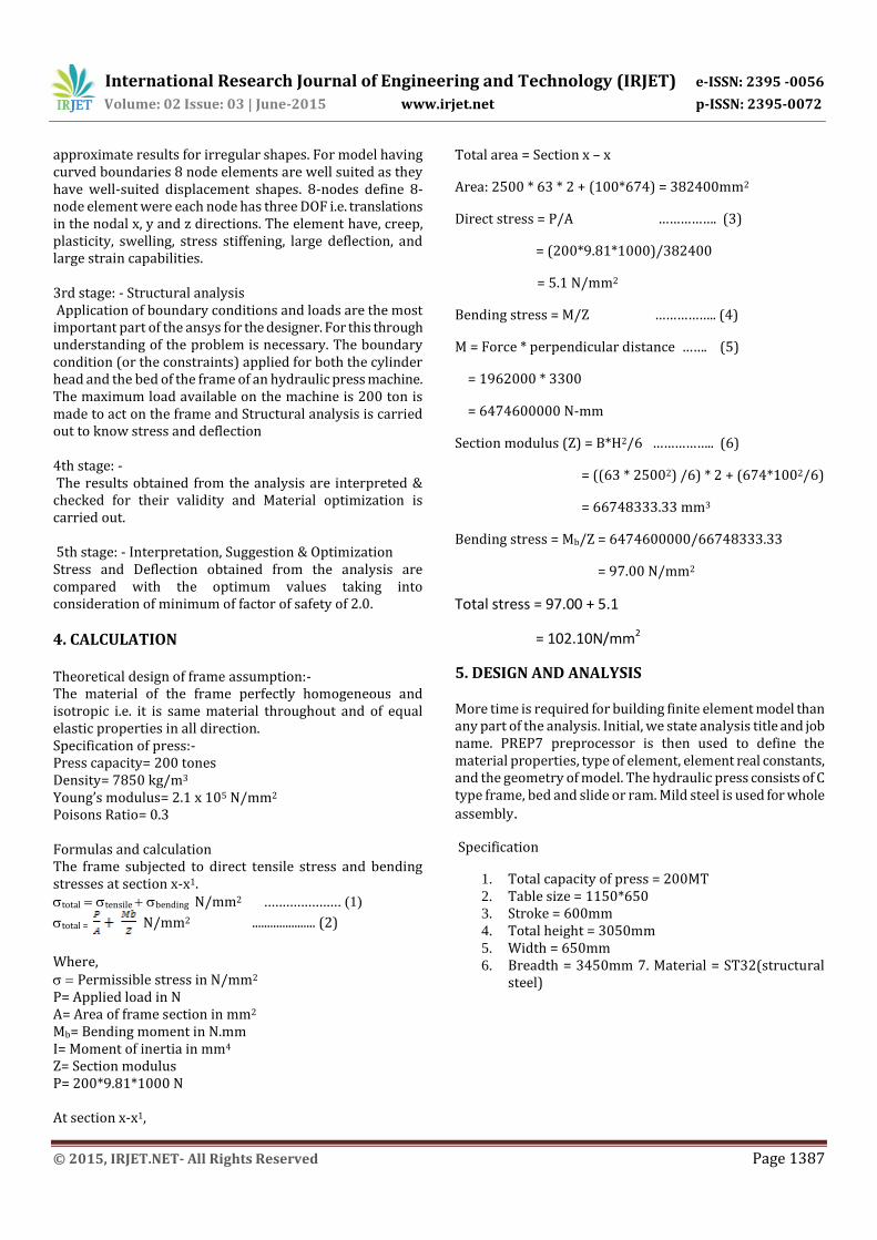
Total area = Section x – x
Area: 2500 * 63 * 2 + (100*674) = 382400mm2
Direct stress = P/A ……………. (3)
= (200*9.81*1000)/382400
= 5.1 N/mm2
Bending stress = M/Z …………….. (4)
M = Force * perpendicular distance ……. (5)
= 1962000 * 3300
= 6474600000 N-mm
Section modulus (Z) = B*H2/6 …………….. (6)
= ((63 * 25002) /6) * 2 + (674*1002/6)
= 66748333.33 mm3
Bending stress = Mb/Z = 6474600000/66748333.33
= 97.00 N/mm2
Total stress = 97.00 + 5.1
= 102.10N/mm2
5. DESIGN AND ANALYSIS
More time is required for building finite element model than any part of the analysis. Initial, we state analysis title and job name. PREP7 preprocessor is then used to define the material properties, type of element, element real constants, and the geometry of model. The hydraulic press consists of C type frame, bed and slide or ram. Mild steel is used for whole
assembly.
Specification
1. Total capacity of press = 200MT 2. Table size = 1150*650 3. Stroke = 600mm 4. Total height = 3050mm 5. Width = 650mm 6. Breadth = 3450mm 7. Material = ST32(structural
steel)

International Research Journal of Engineering and Technology (IRJET) e-ISSN: 2395 -0056
Volume: 02 Issue: 03 | June-2015 www.irjet.net p-ISSN: 2395-0072
© 2015, IRJET.NET- All Rights Reserved Page 1388
Fig- 1: Model of the c type press
Meshing:- After finishing the modeling of solid machine and set up element attributes and setting meshing controls, we are set to generate the finite element mesh. The element size, element shape and midsize placement of node to be used in meshing of the solid model is established by using meshing controls. This step is one of the most important of our entire analysis, for the decisions we make at this stage in our model development will profoundly affect the accuracy and economy of our analysis. For accuracy of result and performance of our analysis this step is one of the most vital step of our entire analysis. Any wrong decision at his stage will affect the whole analysis result. To mesh the machine, SOLID-45 Element (8 node with 3 Degree of Freedom/ node) is used. For this machine free meshing is used. Meshed view is shown below.
Fig- 2: Meshing view of the machine
Boundary Conditions: - Either on the finite element model entities or on the solid model entities we can apply the majority of the boundary conditions and excitations to a harmonic high-frequency analysis. Since the solid model is independent of the underlying finite element mesh, hence applying boundary conditions to the solid model is beneficial. If we use adaptive meshing, successive mesh
refinement does not require reapplying excitation and boundary conditions. The main purpose of this analysis is to observe how the frame structure of machine responds to loading conditions. Specifying the correct load conditions is very important step in analysis. In ANSYS we can apply loads on the model in a variety of ways. By using load step option, during solution we can control use of loads. In this case load is applied to cylinder ram and impact force in applied to the bed or work table and base of the hydraulic press in fixed as shown in figure. 200ton load is applied on the cylinder ram.
Fig- 3: Application of boundary condition
Analysis:- In this case we can apply most of the loads either on finite element model (on elements and nodes) or on the solid model (on lines, key points and areas). Thus on key points or on a node force can be specified. After applying boundary condition, Structural analysis is done to find stress and deflection.
Fig- 4: (a)

International Research Journal of Engineering and Technology (IRJET) e-ISSN: 2395 -0056
Volume: 02 Issue: 03 | June-2015 www.irjet.net p-ISSN: 2395-0072
© 2015, IRJET.NET- All Rights Reserved Page 1389
Fig- 4: (b)
Fig 4 (a), (b) Maximum stress and deformation
Results Obtained: - The Result obtained from the analysis of frame are- 1. The Maximum stress induced in the frame= 74 N/mm2 2. The Maximum Displacement of frame = 0.5395 mm 3. Total weight before optimization= 17366kg
The yield stress of mild steel or structural steel is 250 N/mm2 and Maximum stress induced in the frame is 74 N/mm2 which is very below the yield stress. Therefore now we reduce the frame weight, by making some design changes.
6. OPTIMIZATION
In this period of hard competition, every industry cracks to have an advantage over their complements by Introducing the new products and features to
certain range.
Modifying the previous and making it reliable products.
By reducing the cost of the component without compromising quality and performance.
Decreasing the margins of profit.
By using alternate material for manufacturing.
The main aim of the customer is to get the product of good quality at reasonable price in the market. If the company fulfils the needs of the customer then the company will survive in the market. To survive the company has to modify the product so need to optimize within the available resources. The optimization is done by following three components.
Models Created in ANSYS: For reducing volume of material and weight, the top of frame is made hallow and the top right corner of the frame is cut as shown in fig.
Meshing of model:- To mesh the machine, SOLID-45 Element (8 node with 3 Degree of Freedom/ node) is used. For this machine free meshing is used. Meshed view is shown below.
Fig- 5: Meshing view of optimized model
Boundary condition:- In this case load is applied to cylinder ram and impact force in applied to the bed or work table and base of the hydraulic press in fixed as shown in figure. 200ton load is applied on the cylinder ram.
Fig-6: Application of boundary condition
Analysis:- After applying boundary condition, Structural analysis is done to find stress and deflection.
Fig- 7: stresses in structure after optimization

International Research Journal of Engineering and Technology (IRJET) e-ISSN: 2395 -0056
Volume: 02 Issue: 03 | June-2015 www.irjet.net p-ISSN: 2395-0072
© 2015, IRJET.NET- All Rights Reserved Page 1390
Fig-8: Deflection of Frame after optimization
Results Obtained after optimization: - The Maximum stress induced in the hydraulic press
frame = 102 N/mm2 The Maximum Deflection for 200ton load = 0.6447
mm The stress obtained i.e. (102 N/mm2) is now below
the half of yield stress. Weight = 15420 kg Yield stress of Mild steel is 250MPa The factor of safety = Yield stress / Maximum stress
induced in the machine The factor of safety = 250 / 102 = 2.45
Material reduced”:- By removing the top material of the frame and making it hallow and by cutting the corner of the frame, weight of the hydraulic press frame is reduced from 17366 kg to 15420 kg. Total Weight reduced = 17366- 15420= 1946 kg.
Table – 1: Comparison between results.
Sl
no.
Parameters Before
optimization
After
optimization
1 Maximum stress in the
body.
74N/mm2
102N/mm2
2 Maximum deformation
of the body
0.5mm 0.633mm
3 Weight of the body 17366kg 15420kg
4 Yield strength 250Mpa 250Mpa
5 Factor of safety 3.37 2.45
7. CONCLUSIONS
An attempt was made to analyze and optimize the 200 tone C type hydraulic press using ANSYS software. The project work carried out is successfully designed to meet the
requirements as per the constraints. The C type hydraulic press frame is carefully designed and cross checked where it does meet the requirements. C type hydraulic press machine is designed using optimum material in order to avoid the excess weight. In this project it has been compared original design of C frame type hydraulic press with design that have been optimized by using software tool (ANSYS) it has been demonstrate that, under the same loading conditions, constraints, and intended design purpose ANSYS indentifies a lighter design with reduced material cost.
The maximum stress induced in the machine is 102 MPa which is less than the allowable stress of the material giving Factor of Safety 2.45. Further reduction of material causes unsafe and gives higher deformations and stresses which are not allowable for the machine, as this machine is used for punching and bending operation in sheet metal industries. Were the deformation of the press plays important role to maintain the close tolerance between punch and dies. As analysis shows max deformation found is 0.633mm which is acceptable for such operation and stress induced is 102MPa which is less than less than yield stress 250MPa. Total weight of the machine reduced after optimization is 1946 kg. In this project, it has been shown a 12.62%weight reduction of the C-frame type hydraulic press, which was achieved by changing the design of the frame structure while maintaining structural balance of the hydraulic press and without affecting on performance.
ACKNOWLEDGEMENT
The satisfaction and euphoria that accompany the successful completion of any task would be incomplete without the mention of the people who made it possible, whose constant guidance and encouragement crowned my effort with success.
With immense sense of gratitude I greatly acknowledge my guide, Prof. S.R.KULKARNI Department of Mechanical Engineering, Gogte institute of Technology, Belagavi for providing the required impetus helping and encouragement me to work at Msm Hydro pneumatics Pvt Ltd, Belagavi.
I wish to place on record my thanks to Prof. R.J.NAIK, Head of Department and Dr. A.S. Deshpande, Principal, Gogte Institute of Technology, Belgaum for initiating and encouraging me to carry out my work in Msm Hydro pneumatics Pvt Ltd, Belagavi.
I wish to thank the Staff of Mechanical Engineering Department for their support. This note of gratitude would not be complete without thanking my parents for their constant encouragement, love and care during the work.
My heartfelt thanks to one and all directly and indirectly involved with my work and who were lighthouse during course of my work.

International Research Journal of Engineering and Technology (IRJET) e-ISSN: 2395 -0056
Volume: 02 Issue: 03 | June-2015 www.irjet.net p-ISSN: 2395-0072
© 2015, IRJET.NET- All Rights Reserved Page 1391
REFERENCES
[1] Muni Prabaharan, V. Amarnath-“Structural optimization of 5ton hydraulic press and scrap baling press for cost reduction by topology” International Journal of Modeling and Optimization, Vol. 1, No. 3, August 2011.
[2] P.D.Murarka, S.P.Sinha-“Computer-aided design of hydraulic press structures”, Vol. 10,No. 9,pp. 637-645, Mathematical and computer modelling 1988.
[3] A. G. Naik, N. K. Mandavgade “FEA Implementation in Analysis and Optimization of Top and Bottom Frame For Hydraulic Cotton Lint Bailing Press” ISSN 2229-5518 Volume 3,Issue 7, July-2012, ARPN Journal of Engineering and Applied Sciences.
[4] M. Fulland, M. Sander, G. Kullmer, H.A. Richard-“Analysis of fatigue crack propagation in the frame of a hydraulic press”, Vol. 1, Issue 5, Jan 2007 Engineering Fracture Mechanics.
[5] Frantisek Trebuna- “Analysis of crack initiation in the
press frame and innovation of the frame to ensure its further operation”2011,vol. 45, International journal for scientific research & development.
[6] Santoshkumar S, Prof. Yogita N. Potdar, Prof. A. C.Mattikalli- “Analysis and structural optimization of 5 ton h-frame hydraulic press”Vol. 1 Issue 5, July 2014 International Journal of Innovative Science, Engineering & Technology.
[7] B.Parthiban, P.Eazhumali, S.karthi, P.Kalimuthu (2014)-“Design and analysis of C type hydraulic press structure and cylinder”.Vol.2 Issue.3, March2014.Pgs: 47-56 International Journal of Research in Aeronautical and Mechanical Engineering.