Embed Size (px)
Citation preview
Ai-Rt72 879 EXPLORATORY DEVELOPMENT OF VHF (VERY NIGH FREOUENCY ) i/QUARTZ CRYSTAL RESONATORS(U) PIEZO TECHNOLOGY INCORLANDO FLA R C SNYTHE ET AL JUL 86 RADC-TR-86-68
UNCLASSIFIED F19628-83-C-886i F/6 9/1 I L
EIIIIIIIIIIhIEllhlllhllhllElllllhhlhIIIIEEEEIEEEllIEEEEI/flfl/I/fl/lI
LII
1.25 111,- . 111111.6
MICROCOPY RESOLUTION TEST CHART
NATIONAL BUREAU OF SIANOARDSlA63-A
RADC-TR-86-60Final Technical ReportJuly 196.
0 EXPLORATORY DEVELOPMENT OF VHFp,- QUARTZ CRYSTAL RESONATORS
Plezo Technology, Inc. DT1C"DTIC
ELEC TE
OCT 1686Robert C. Smythe and John R. Hunt
AB
APPROVED FOR PUBLIC RELEASE; DISTRIBUTION UNLIMITED
''. C.
"; ~ROME AIR DEVELOPMENT CENTERAir Force Systems Command
Griffiss Air Force Base, NY 13441-5700
86 1o 16 158
" ..,....,.... .... ...... " .- ... .-... ... .......-......... ;............:...:... :............-..
-I' .,,.-: c--;,,- -, -
This report has been reviewed by the RADC Public Affairs Office (PA) andis releasable to the National Technical Information Service (NTIS). At NTISit will be releasable to the general public, including foreign nations. .
RADC-TR-86-60 has been reviewed and is approved for publication.
APPROVED:
HERBERT G. LIPSONProject Engineer
APPROVED:
HAROLD ROTH, DirectorSolid State Sciences Division
FOR THE COMMANDER: ' "" "
JOHN A. RITZPlans & Programs Division
If your address has changed or if you wish to be removed from the RADCmailing list, or if the addressee is no longer employed by your organization,please notify RADC (ESES) Hanscom AFB MA 01731-5000. This will assist us in 4maintaining a current mailing list.
Do not return copies of this report unless contractual obligations or noticeson a specific document requires that it be returned.
4 A. A ."
UNCLASSIFIEDSECURITY CLASSIFICATION OF THIS PAGE
REPORT DOCUMENTATION PAGEIa. REPORT SECURITY CLASSIFICATION M ITVf j
UNCLASSIFIED as2a SECURITY CLASSIFICATION AUTHORITY 3. DISTRIBUTIONI AVAILABILITY OF REPORT
N/A Approved for public release; distribution2b. DECLASSIFICATION/DOWNGRADING SCHEDULE unlimited.N/A unliited.
4. PERFORMING ORGANIZATION REPORT NUMBER(S) S. MONITORING ORGANIZATION REPORT NUMBER(S)
N/A PADC-TR-86-60
68. NAME OF PERFORMING ORGANIZATION 16b. OFFICE SYMBOL 7a. NAME OF MONITORING ORGANIZATIONI Tf applicable) Rome Air Development Center (ESES)
Pieza Technology, Inc.
6c. ADDRESS (City, State, and ZIP Code) 7b ADDRESS (City, State, and ZIP Code)
2525 Shader Road Hanscom AFB HA 01731-5000P.O. Box 7859Orlando FL 32854-7859
&a. NAME OF FUNDING/SPONSORING 8b OFFICE SYMBOL 9 PROCUREMENT INSTRUMENT IDENTIFICATION NUMBERORGANIZATION (If apicable)Rome Air Development Center ESES F19628-83-C-0061
8c. ADDRESS (City, State, and ZIP Code) 10 SOURCE OF FUNDING NUMBERSPROGRAM PROJECT TASK WORK UNIT
Hanscom AFB MA 01731-5000 ELEMENT NO NO. NO ACCESSION NO
62702F 4600 18 53
11 TITLE (Include Security Classfication)EXPLORATORY DEVELOPMENT OF VHF QUARTZ CRYSTAL RESONATORS
12. PERSONAL AUTHOR(S)Robert C. Smythe, John R. Hunt
13a. TYPE OF REPORT 13b. TIME COVERED 14. DATE OF REPORT (Year, Month, Day) S PAGE COUNTFinal FROM Feb83 TO Sep85 July 1986 76
16. SUPPLEMENTARY NOTATION
N/A
17. COSATI CODES 18. SUBJECT TERMS (Continue on reverse if necessary and identify by block number)
FIELD GROUP SUB-GROUP Very High Frequency Quartz Resonators Sweeping
03 Chemical Etching17 07 Etch Channels
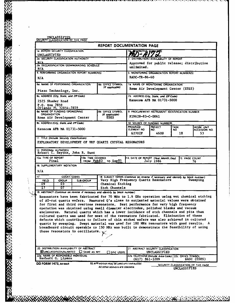
S19 ABSTRACT (Continue on reverse if necessary and identify by block number)
Resonators have been fabricated for 70 MHz to 1.6 GHz operation using wet chemical etchingof AT-cut quartz wafers. Measured Q's close to estimated material values were obtainedfor first and third overtone resonators. Best performance for very high frequencyoperation was obtained using small diameter electrodes, polished blanks and vacuumenclosures. Natural quartz which has a lower incidence of etch channels and pits than
. . cultured quartz was used for most of the resonators fabricated. Elimination of thesedefects which contribute to failure of thin etched wafers was also achieved in culturedquartz by sweeping. Swept material was used for 100 MHz resonators with good results. Abreadboard circuit operable to 150 MHz was built to demonstrate the feasibility of usingthese resonators in oscillators.
20. DISTRIBUTION/AVAILABILITY OF ABSTRACT 21 ABSTRACT SECURITY CLASSIFICATION
&)UNCLASSIFIED/UNLIMITEo 0 SAME AS RPT 0 DTIC USERS UNCLASSIFIED22a. NAME OF RESPONSIBLE INDIVIDUAL 22b TELEPHONE (Include Area Code) 22c. OFFICE SYMBOLHerbert G. Lipson (617) 861-3209 RADC (ESES)
D FORM 1473, 84 MAR 83 APR edition may be used until exhausted SECURITY CLASSIFICATION OF THIS PAGEAll other editions are obsolete. UNCLASSIFIED
TABLE OF CONTENTS
Page
Introduction 1
1.1 Goals 1
1.2 Applications And Benefits 1
2 Technical Discussion 3
2.1 Ring-Supported Resonators 3
2.2 Fabrication 5
2.3 Experimental Results 14
2.3.1 70 MHz Fundamental Resonators 14
2.3.2 100 MHz Fundamental Resonators 19
2.3.3 150 MHz Fundamental Resonators 32
2.3.4 250 MHz Third Overtone Resonators 32
2.3.5 450 MHz Third Overtone Resonators 38
2.3.6 UHF Fundamental Resonators 38
2.3.7 Oscillator Circuit 56
2.4 Electrodiffusion Of Quartz 58
2.5 Surface Finish Effects 63
2.6 Summary Of Results 66
3 Conclusion 67
Ref erences 68
Disit
i ~2IV
1 Introduction
1.1 Goals
The purpose of this program is the exploratory development of VHF and UHF
AT-cut quartz crystal resonators utilizing high fundamental frequencies.
Specific program objectives are the fabrication of fundamental mode resonators
at 70, 100 and 150 MHz and third overtone resonators at 250 and 450 MHz.
These objectives have been met. In addition the feasibility of using wet
chemical etching to fabricate AT-cut resonators at fundamental frequencies up
to 1.6 GHz has been demonstrated.
1.2 Applications and Benefits
The generation of high frequencies is required in a wide range of
military (and commercial) VHF, UHF, and microwave systems including
communications, navigation, radar, and next-generation high speed logic
systems. High frequencies may be generated either directly or by frequency
multiplication.
The direct generation of high frequencies offers well known advantages
over frequency multiplication. First, direct generation is simpler, resulting
in reduced size, weight, cost, and power consumption [1]. Second, since
frequency multiplication increases phase noise by 6 dB each time the frequency
is doubled, direct generation allows improved phase noise to be obtained
[2]. The availability of higher frequency resonators would in some instances
allow frequency multiplication to be replaced with direct generation and in
other instances would reduce the multiplication required.
"i " ,"' ,", - -
Floth bulk wave and SAW resonators have uses in high frequency
generation. SAW resonator advantages are maximum frequency range, power
handling ability, and potentially low cost in high volume applications, due to
batch processing.
High frequency bulk wave resonators offer advantages over SAW resonators
with regard to aging, temperature stability, vibration sensitivity, and
acoustic noise sensitivity. In addition, due to better 0, capacitance ratio
(r), and figure of merit (M - Q/r), bulk wave resonators afford circuit
simplicity, improved phase noise, and high pullability.
-.
% ,.%
S2
IIR -2-
2 Technical Discussion
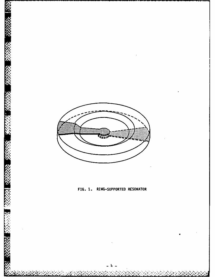
2.1 Ring-Supported Resonators
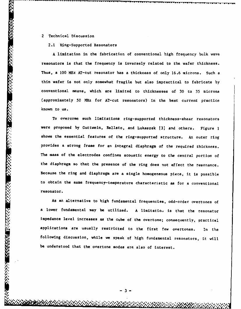
A limitation in the fabrication of conventional high frequency bulk wave
resonators is that the frequency is inversely related to the wafer thickness.
Thus, a 100 MHz AT-cut resonator has a thickness of only 16.6 microns. Such a
thin wafer is not only somewhat fragile but also impractical to fabricate by
conventional means, which are limited to thicknesses of 30 to 35 microns
(approximately 50 MHz for AT-cut resonators) in the best current practice
known to us.
To overcome such limitations ring-supported thickness-shear resonators
were proposed by Guttwein, Ballato, and Lukaszek [3] and others. Figure 1
shows the essential features of the ring-supported structure. An outer ring
provides a strong frame for an integral diaphragm of the required thickness.
The mass of the electrodes confines acoustic energy to the central portion of
the diaphragm so that the presence of the ring does not affect the resonance.
Because the ring and diaphragm are a single homogeneous piece, it is possible
"4 to obtain the same frequency-temperature characteristic as for a conventional
resonator.
As an alternative to high fundamental frequencies, odd-order overtones of
a lower fundamental may be utilized. A limitatioL is that the resonator
impedance level increases as the cube of the overtone; consequently, practical
applications are usually restricted to the first few overtones. In the
following discussion, while we speak of high fundamental resonators, it will
be understood that the overtone modes are also of interest.
k
-3-
;4i';
1~q~
-w
.~I.
~r~y FIG. 1. RING-SUPPORTED RESONATOR
p-b.
5-
Sb.
-'S.
~II~
S.
2.2 Fabrication
While the advantages of the monolithic support-ring concept are obvious,
fabrication difficulties have limited its exploitation. Methods which may be
considered for forming the diaphragm in a suitably lapped and polished wafer
include:
1) Ion milling (reactive and non-reactive)
2) Reactive plasma etching
3) Chemical etching.
Argon ion milling for this application has been actively pursued in
France for several years. Berte [41, [51 successfully fabricated ring-
supported resonators and monolithic filters using non-reactive ion milling to
form the diaphragm, and ring-supported resonators, oscillators, and filters
are now commercially available in France [6], [7]. AT-cut resonators with
fundamental frequencies to 600 MHz have been made [8], and AT-cut fundamentals
up to at least 200 MHz are offered commercially. BT- and SC-cuts are also
available, as well as X-cut lithium tantalate resonators.
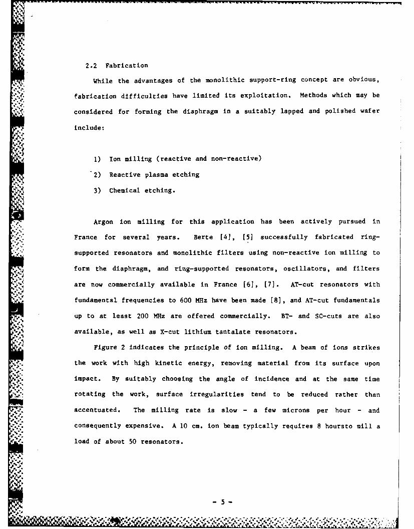
Figure 2 indicates the principle of ion milling. A beam of ions strikes
the work with high kinetic energy, removing material from its surface upon
impact. By suitably choosing the angle of incidence and at the same time
rotating the work, surface irregularities tend to be reduced rather than
accentuated. The milling rate is slow - a few microns per hour - and
consequently expensive. A 10 cm. ion beam typically requires 8 hoursto mill a
load of about 50 resonators.
-5-
1' Np- rO
- v-wr-~~~-w~-r-r~~r- r-W- -'rrr w w-, in w - m - xr p '-inF.*.rW ~
,:
1 1ION BEAM
GLASS MASK
QUARTZ WAFER
'a
COOLING WATER
FIG. 2. FIXTURE ARRANGEMENT FOR ION MILLINGOF RING-SUPPORTED RESONATOR (AFTER BERTE)
I -6-
Work has been done at TRW [9] using an ion beam composed of a mixture of
non-reactive argon gas and reactive perfluoroethane gas. This gas mixture is
said to eliminate undesirable trenching and redeposition observed along the
edges of the wells formed with argon ion milling alone. Utilizing this
technique, etch rates as high as 30 microns per hour have been reported and
devices fabricated with fundamental frequencies of 200 MHz.
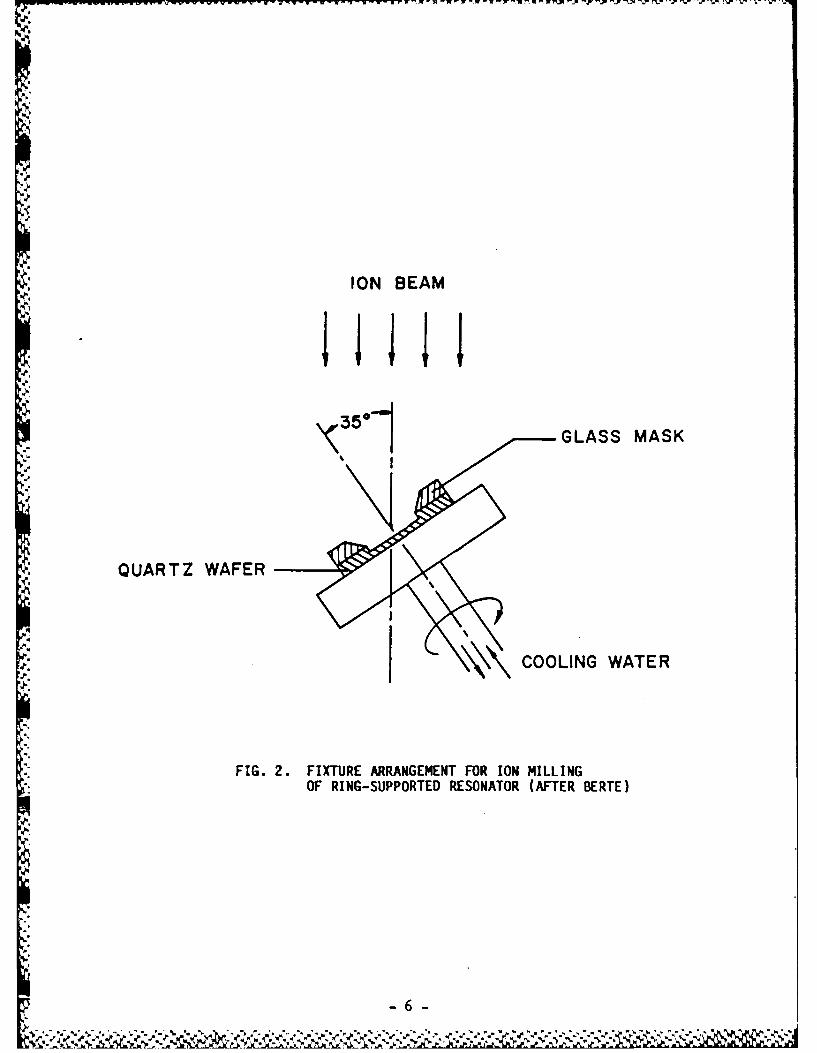
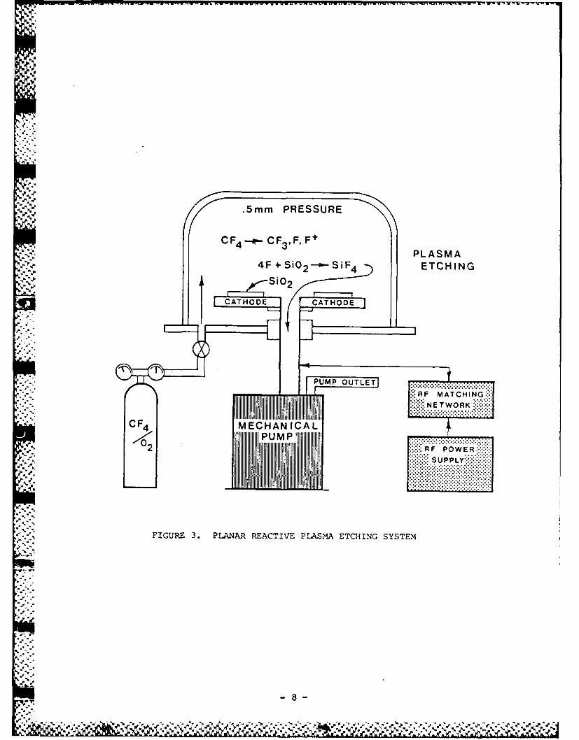
Reactive plasma etching is widely used in semiconductor processing.
Limited work at PTI prior to this program indicates that moderately high stock
removal rates can be obtained; however, there was considerable evidence of
surface damage. Figure 3 shows the planar etching system used. Because the
etch rate is fairly high and a large number of wafers can be etched
simultaneously, plasma etching is potentially a low-cost process, but requires
further development.
Chemical etching has been used for many years in the crystal industry to
remove wafer damage caused by mechanical lapping. New insight into etching
has been provided by the work of Vig and co-workers [10], who introduced the
depletion-layer concept to explain improvements in surface roughness which
they observed. They speculated that chemical etching might be used to fabri-
cate the ring-supported resonator wafer.
The feasibility of using chemical milling to form the ring-supported
structure was demonstrated at PTI prior to the present program. Nevertheless,
it was not certain whether all program objectives could be met using the
process. Therefore, it was initially planned to investigate not only chemical
milling but also plasma etching and ion milling. The favorable results
obtained with chemical milling, however, and the relative simplicity of the
technique, made it advisable to concentrate on it to the exclusion of the
other processes.
~. A7
-~r
.5mm PRESSURE
CF 4 ..-- F3,F FtPLASMA4 F +Si0 2 ---- S iF 4 ETCHING
I S'0 2
CATHOMTCING:E
N E T WOR KJ
F4 MCAIA
2 ::::RF POWER:"'
SUPPLY~
FIGURE 3. PLANAR REACTIVE PLASMA ETCHING SYSTEM
-8-
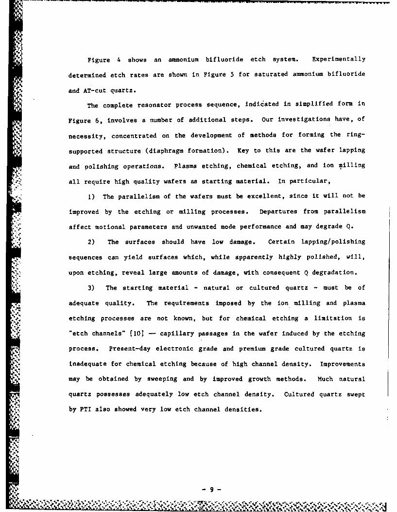
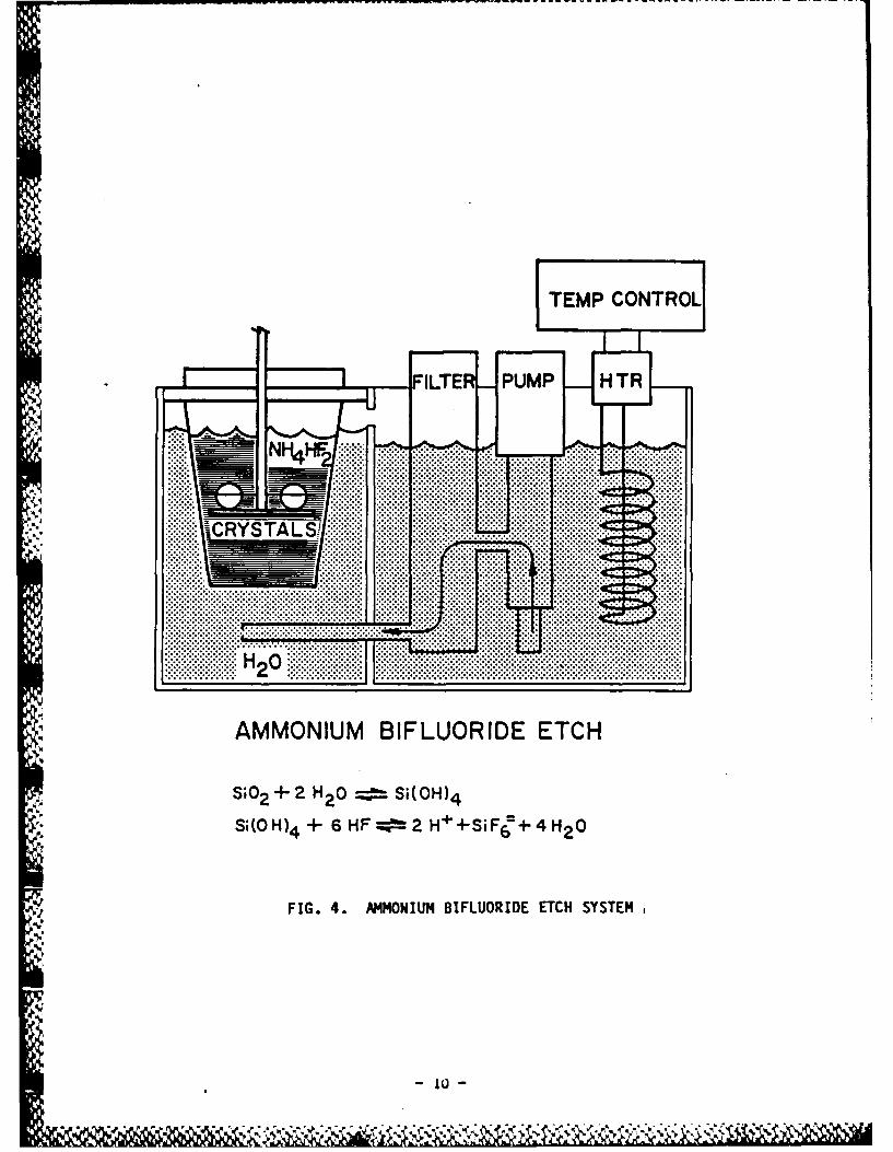
Figure 4 shows an ammonium bifluoride etch system. Experimentally
determined etch rates are shown in Figure 5 for saturated ammonium bifluoride
and AT-cut quartz.
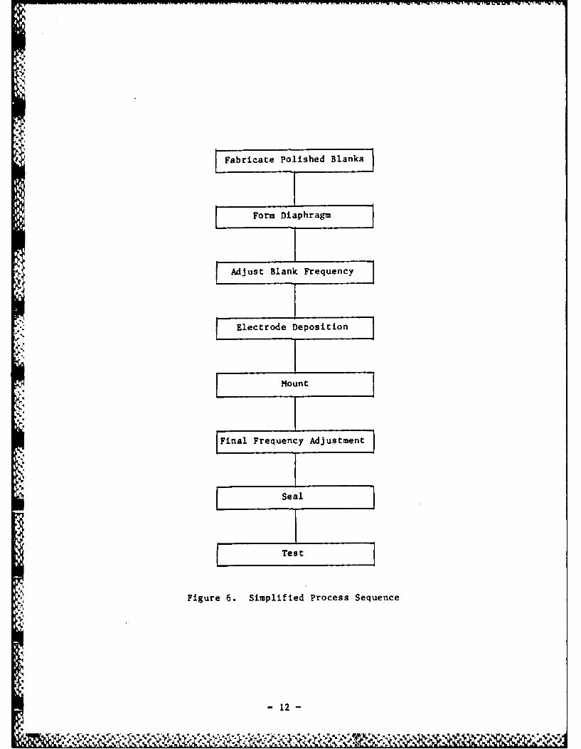
The complete resonator process sequence, indicated in simplified form in
Figure 6, involves a number of additional steps. Our investigations have, of
necessity, concentrated on the development of methods for forming the ring-
supported structure (diaphragm formation). Key to this are the wafer lapping
and polishing operations. Plasma etching, chemical etching, and ion milling
all require high quality wafers as starting material. In particular,
1) The parallelism of the wafers must be excellent, since it will not be
improved by the etching or milling processes. Departures from parallelism
affect motional parameters and unwanted mode performance and may degrade Q.
2) The surfaces should have low damage. Certain lapping/polishing
sequences can yield surfaces which, while apparently highly polished, will,
upon etching, reveal large amounts of damage, with consequent Q degradation.
3) The starting material - natural or cultured quartz - must be of
adequate quality. The requirements imposed by the ion milling and plasma
etching processes are not known, but for chemical etching a limitation is
' "etch channels" (101 - capillary passages in the wafer induced by the etching
process. Present-day electronic grade and premium grade cultured quartz is
inadequate for chemical etching because of high channel density. Improvements
may be obtained by sweeping and by improved growth methods. Much natural
quartz possesses adequately low etch channel density. Cultured quartz swept
by PTI also showed very low etch channel densities.
-9-
TEMP CONTROL
AMMNM ILUORIDEM ETCH
NH .....
.;2 + ..... ... .S..(... ..S;OH. .... .... ............
.... ... ... ..
. . . . . .
FIG.S 4... ..... ILU DEEC SSE
... . . . . . . .. . ... .. ...
........ .. .. . . .. . .
- ~~~~~~ .9w-'w - . .- . -
AA
2.1
0. - - -0 -5 -0 75 9
TEPEAUR (C
I.S THRT S I-RTRSAUAED44F
Fabricate Polished Blanks
ZI3IZZ
S Form Diaphragm
N:.,,,Mount
[FnFreqency dstment
'9!
: Figure 6. Simplified Process Sequence
e - 12 -
In the chemical etching process the use of unpolished blanks may be
considered, as etching removes material damaged by lapping and at the same
time reduces surface roughness. There are two limitations:
1) Surface finish may not be adequate to obtain desired Q.
2) Parallelism obtained in lapping is generally inferior to that
* obtained by polishing, with the consequences mentioned earlier. The
parallelism of unpolished blanks cannot be accurately measured by standard
techniques. On the other hand, the parallelism of polished blanks can easily
be measured by observing self-interference fringes under monochromatic light.
Despite these restrictions, the use of carefully prepared, unpolished
blanks cannot be ruled out in all instances.
V
Jr.N
- 13 -
.,:~A
p
2.3 Experimental Results
Using chemical milling with ammonium bifluoride, resonators were
fabricated at frequencies from 70 MHz to 1.6 GHz. The work began with 70 MHz
units and proceeded, for the most part, in order of increasing fundamental
frequency.
2 Resonator parameter measurements were made using an automatic measurement
system utilizing the H-P 4191A Impedance Analyzer [1l1. Mode plots employed
either an H-P 140 series spectrum analyzer/tracking generator, an H-P 3577A
network analyzer, or a Polarad ZPV vector analyzer in conjunction with an H-P
8662A synthesized signal generator.
2.3.1 70 MHz Fundamental Resonators
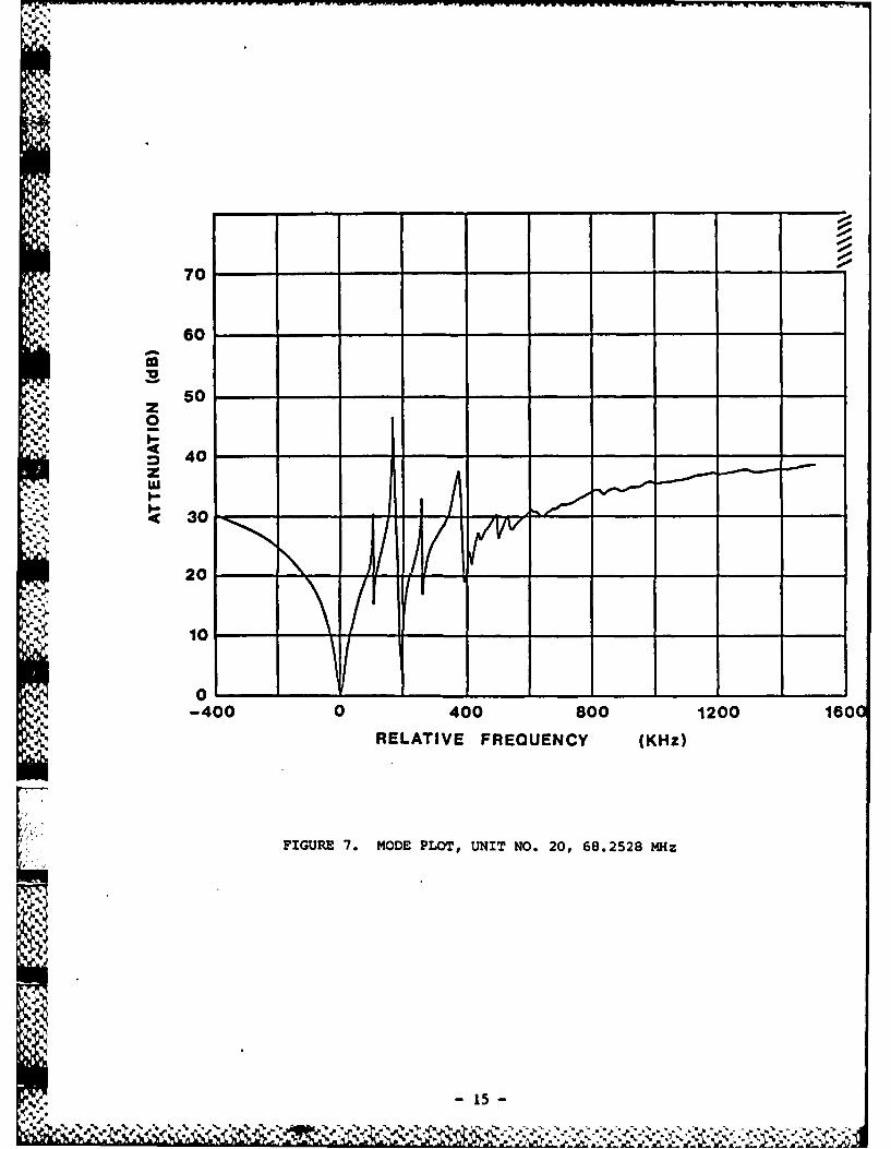
The first 70 MHz units had a blank diameter of 0.25 inch and aluminum
electrodes 40 mils in diameter, were mounted in PTI type "F" enclosures
(similar to HC-18), and sealed in dry nitrogen atmosphere. Figure 7 is a mode
plot for one of these units, while Table 1 presents the equivalent circuit
parameter values for the fundamental mode and two unwanted responses.
The electrode diameter of 40 mils was used initially in order to make use
of an available mask. Subsequently, a 20 mil mask was fabricated, and
additional units were made having 20 mil electrodes, also sealed in a dry
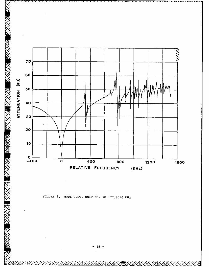
nitrogen atmosphere. Table 2 contains measured parameter data. Figure 8 is a
mode plot for one of these units and is fairly typical, although there is
considerable unit-to-unit variation. Decreasing the electrode diameter
increased the spacing between the fundamental and anharmonic modes, as
- 14 -
"% . % % V V,4,%
70
. 60. 10
so
',- 1004r08 012 01 0
70
30
50
00
~ 0
".RELATIVE FREQUENCY (KHz)
l,,,.: FIGURE 7. MODE PLO'T, UNIT NO. 20, 68.2528 MHz
'gz
Ew
105
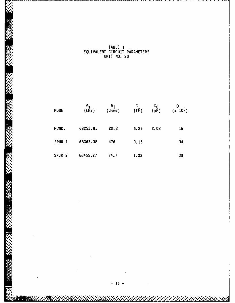
TABLE 1EQUIVALENT CIRCUIT PARAMETERS
UNIT NO. 20
fs R1 Cl CO QMODE (kHz) (Ohms) (fF) (pF) (x1)
FUND. 68252.81 20.8 6.85 2.08 16
SPUR 1 68363.38 476 0.15 34
,, SPUR 2 68455.27 74.7 1.03 30
- 16-
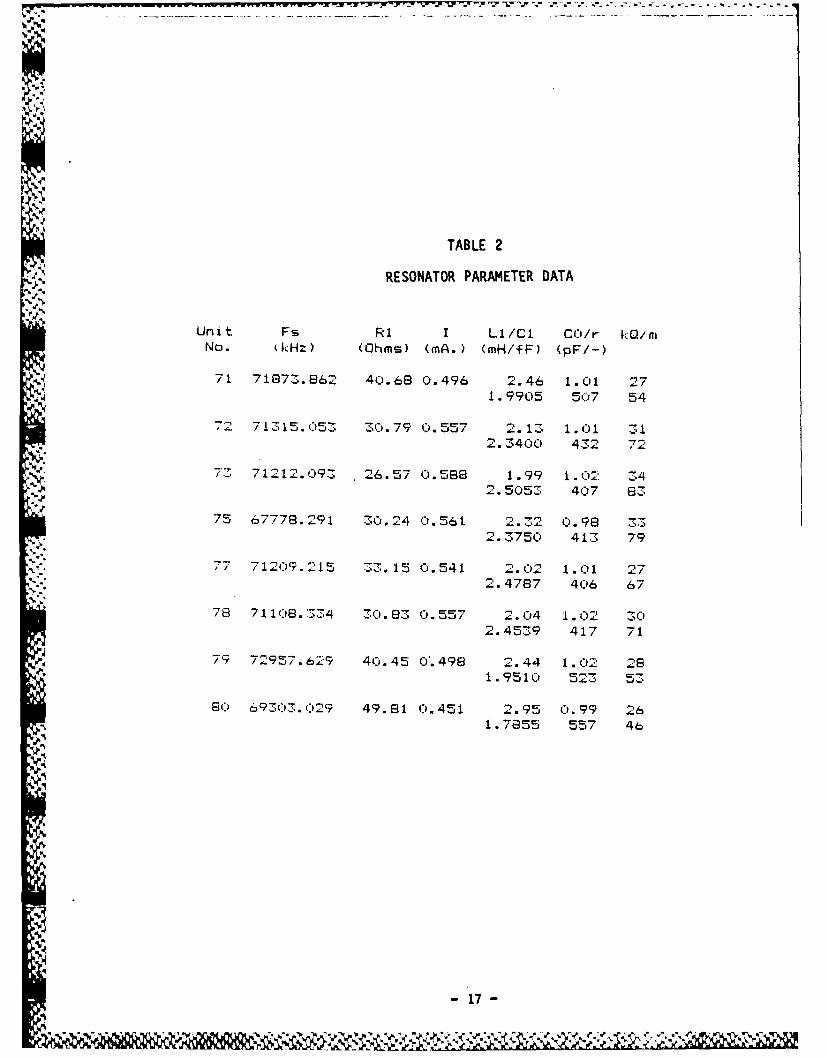
TABLE 2
RESONATOR PARAMETER DATA
Unit Fs R1 I Li/Cl CO/r kQiraNo. (kHz) (Ohms) (mA.) (mH/fF) (pF/-)
71 71873.862 40.68 0.496 2.46 1.01 271. 9905 507 54
72 71315.C53 30.79 0.557 2. 13 1.01 312. 3400 432 72
7 71 2 121.093 26.57 ).58e 1.99 1.02 342.5053 407 83
75 67778.291 30.24 0.561 2.32 0.98 332.3750 413 79
7 -109.215 33. 15 0.541 2.02 1. C01 272.4787 406 67
7e 71108.334 30.83 0.557 2.04 1.02 302.4539 417 71
79 72957.629 40.45 0'.498 2.44 1.02 281.9510 523 53
80 69303.029 49.81 0.451 2.95 0.99 261.7855 557 46
17!
NM
70 ._ _
60
50 ,
S 40z
S30
20- -_ _ _ __ _
10__ ___ _ __ _
-400 0 400 800 1200 1600RELATIVE FREQUENCY (KHz)
FIGURE 8. MODE PLOT, UNIT NO. 78, 72.9576 milz
m
-18-
-v - - -
predicted hy trapping theory. The first unwanted mode was typically more than
300 kHz above the fundamental mode. This is an antisymmetric mode, but is
- weakly excited due to slight unavoidable asymmetry of the resonator structure.
44 There was also an increase in Q from an average of 15 thousand to 30 thousand,
which may have been due to process improvement.
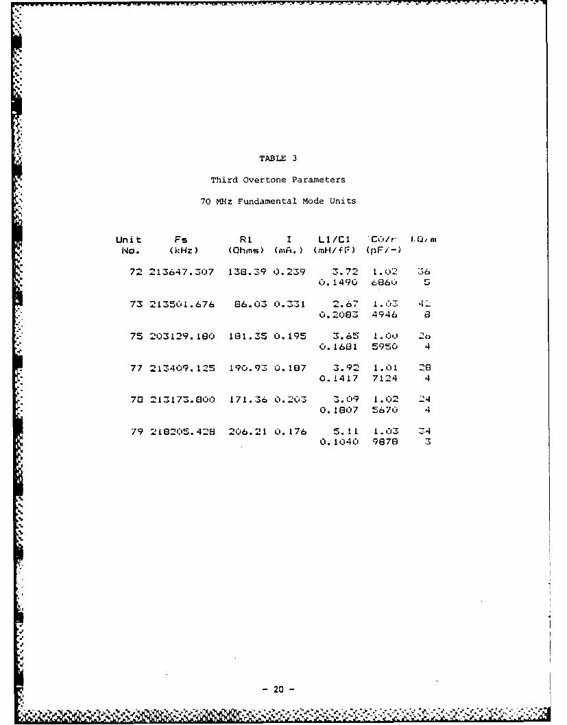
The third overtone (210 MHz) parameters of these latter units were also
measured, Table 3. Q's were excellent. Unwanted mode plots were not made,
but mode scans were visually examined. Unwanted mode performance, while not
excellent, is entirely adequate for oscillator applications.
The polishing process used for these 70 MHz resonators resulted in a
significant number of scratches which were deepened by the etching process.
The polishing step also hid many other forms of surface damage, which were not
revealed until the blanks were etched. While the incidence of scratches and
other defects was variable from batch to batch, the occurrence was
sufficiently frequent to seriously limit device yield. Accordingly, it was
decided to attempt to utilize unpolished wafers and, at the same time, to
evaluate an alternative polishing process.
2.3.2 100 MHz Fundamental Resonators
To test the feasibility of using unpolished wafers, a group of natural
quartz blanks was pinlapped to 29 MHz using 1 micron abrasive, etched to 100
!. ... MHz in ammonium bifluoride, plated with 20 mil aluminum electrodes, and sealed
in dry nitrogen. The etched surfaces resembled those reported by Vig and co-
workers [10] and were essentially scratch-free. Scanning electron micrographs
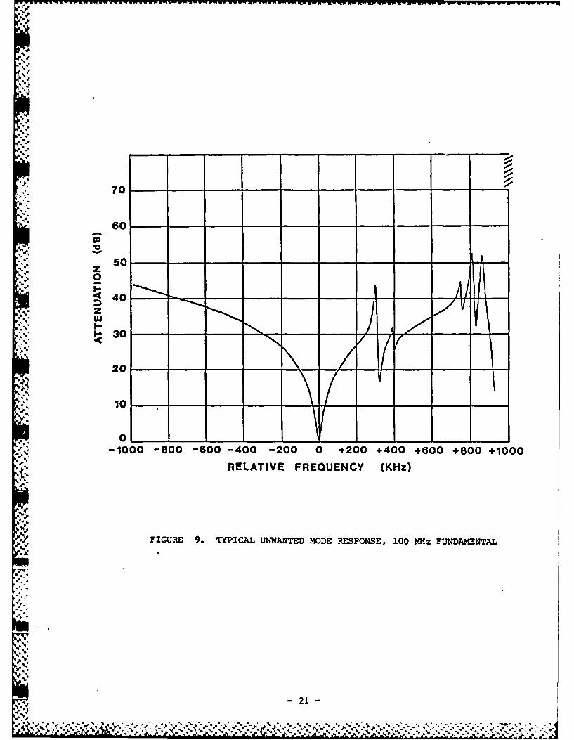
of these surfaces are given in Section 2.5. The mode scan of figure 9
indicates acceptable unwanted mode rerponse typical of the group. Third
-19-
TAB LE 3
Third overtone Parameters
70 MHz Fundamental Mode Units
Unit F s RI I Li/Cl 'C6/r- -../OatNO. (1kHz) (Ohmns) (i. ) (mH/f F) (pF/-)
72 213647.307 138.379 0. 239 1.7 1. 02 :,C). 1490 6~860'
73 213501.676 66.03 031 2. 67 1 . OZ 4.0.28 4946 0
75 2103129.1160 181.Z5 0.195 3. 6' 1 .O 000.1681 5950 4
77 213409.125 190..93 0. 16E7 3.92 1.01 20.1417 7124 4
70 2 1:;173.680o 171.36 0.203 3>.09 1 . 02 240.1607 5670 1
79 2 L13205. 426 206.21 0. 176 5.11 1 .03 Z40. 1040 98768
420
.70
.J. -
- 50 - - __ -
• . I- 3 A
so
~40Z
*555 130
20
-1000 -800 -600 -400 -200 0 +200 +400 +600 +800 +1000RELATIVE FREQUENCY (KHz)
FIGURE 9. TYPICAL UNWANTED MODE RESPONSE, 100 MHz FUNDAMENTAL
.
- 21 -
~ .~*:~-~Z- ~ ~ ~ ~3;
overtone mode measurements, however, show multi-moded responses, indicating
lack of adequate parallelism. Fundamental mode parameter measurements, Tahle
4, show O's below 10,000, considerably below values obtained using polished
blanks. The low Q was attributed to the surface finish, although non-paral-
lelism may also have been a factor.
It was felt that while the results obtained using unpolished wafers might
4. be improved somewhat with further effort, their use imposes serious limits on
the Q-f product obtainable. Therefore, an alternative polishing process was
evaluated. Wafers polished using this process remained essentially free of
scratches after etching. A group of 100 MHz fundamental mode resonators was
fabricated by etching natural quartz blanks which had been polished using this
improved process. The etched units were plated with 20 mil aluminum
. electrodes and sealed in dry nitrogen. As shown in Table 5, the parameters of
these resonators are fairly uniform, indicating the reproducibility of the
process. Q's are typically 25 thousand, with motional resistances as low as
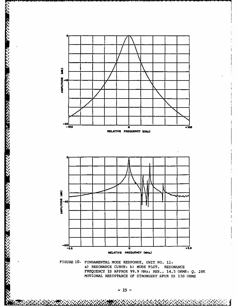
17 ohms. A typical resonance curve and mode plot are shown in figure 10. The
motional resistance of the strongest anharmonic mode is approximately 9 times
that of the main mode. The closest significant anharmonic is approximately
600 kHz above the main mode. Mode locations are in good agreement with
theory.
'22
N.
% %
- 22-- -,, i
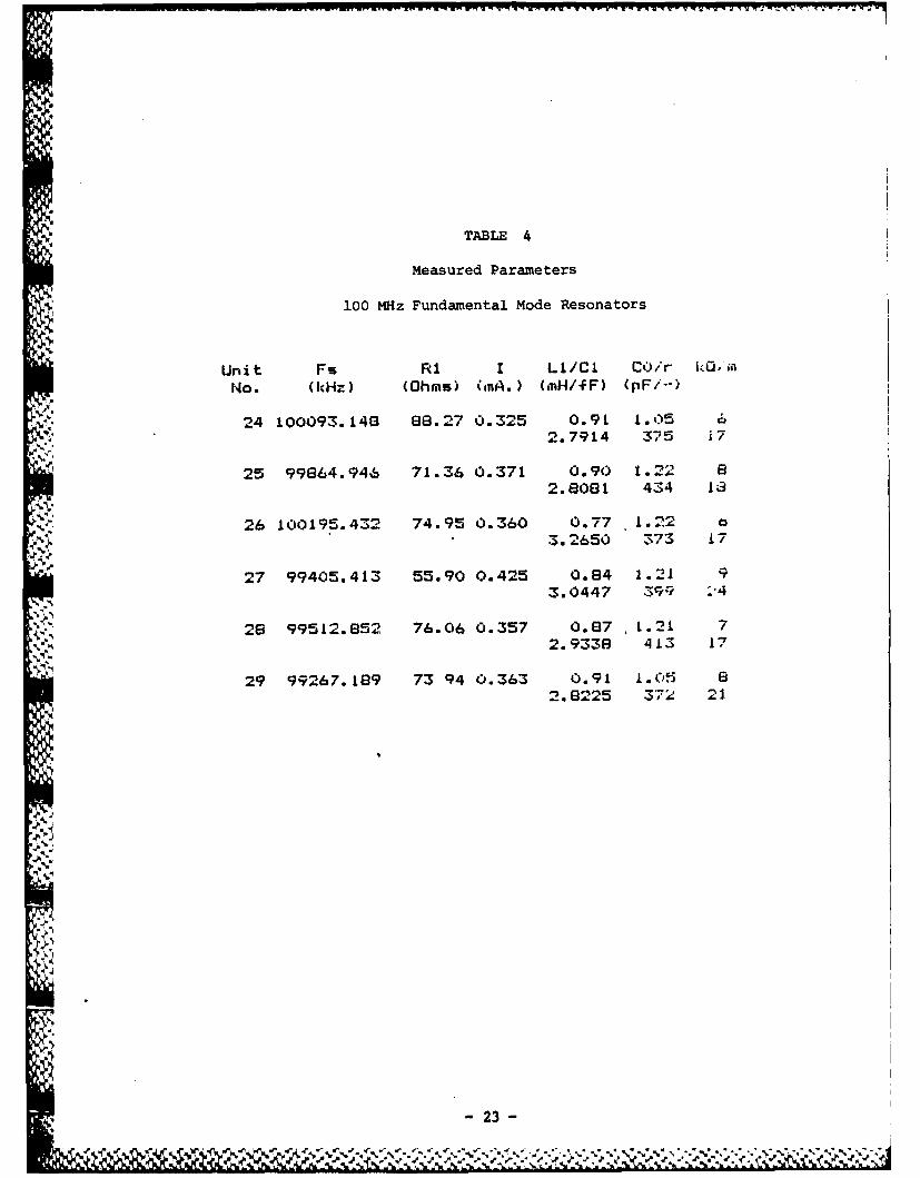
TABLE 4
Measured Parameters
100 MHz Fundamental Mode Resonators
Unit Fs RI I LI/Cl CO/r kO.i
No. (kHz) (Ohms) (nA.) (MH/fF) (pF/--)
24 100093.148 88.27 0.325 0.91 1.05
5,.,2.7914 325 j7
25 99864.946 71.36 0.371 0.90 1.2 82. 8081 434 1;3
26 100195.432 74.95 0.360 0.77 L.22
:3. 2650 373 17
27 99405.413 55.90 0.425 0.84 1.21 93.0447 399 :-4
28 99512.852 76.06 0.357 0.87 , 1.21 7
2.9338 413 17
29 99267.189 73 94 0.363 0.91 1.05 82.8225 37: 21.
" S ,
- 23 -
.," ' " - ',"V ,.. .", . . , ,", v ," ¢ .". ,'.. ." ". % ..."';...'.. *." %. **." ." ". " ..*.
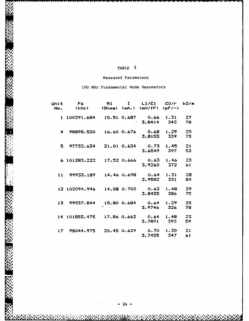
TABLE 5
Measured Parameters
100 MHz Fundamental Mode Resonators
Unit Fs R1 I LI/Cl CO/r kO/mNo. (kHz) (Ohms) (mA.) (mH/fF) (pF/-)
V 1 100291.684 15.51 0.6e7 0.66 1.31 27. 3.8414 342 78
4 96698.530 16.60 0.676 0.68 1.29 253.8155 339 75
5. 97732.634 21.01 0.634 0.73 1.45 213.6549 397 53
6 1012e3.222 17.52 0.666 0.63 1.46 233.9260 372 61
11 99933.189 14.46 0.698 0.64 1.31 283.9582 331 84
12 102094.946 14.08 0.702 0.63 1.46 293.8455 386 75
13 99537.844 15.80 0.684 0.64 1.29 253.9746 326 78
14 101855.475 17.86 0.663 0.64 1.48 233.7891 392 59
17 98044.975 20.45 0.639 0.70 1.30 213.7455 347 61
- 24 -
%0
S--20-
-100 0 #,100RE~LATIVE FREQUENCY CKW~.
'. Ls 0 #24.
V,.
,o IRILATIVl FREQUENCY (MHZ.)
FIGURE 10. FUNDAMENTAL MODE RESPONSE, UNIT NO. 11:~a) RESONANCE CURVE: b) MODE PLOT. RESONANCE
FREQUENCY IS APPROX 99.9 MHz; RES., 14.5 OHMS: Q. 28KMOINLRESISTANCE OF STRONGEST SPUR IS 130 OHMS
- - - --25-
, . . . ", r!'! . ' "- " " " "" '. ,7" ,""i" ,',,,'" . ,' , % .-. ,. <,% .++' % ,',,",, ,,",+"....4.
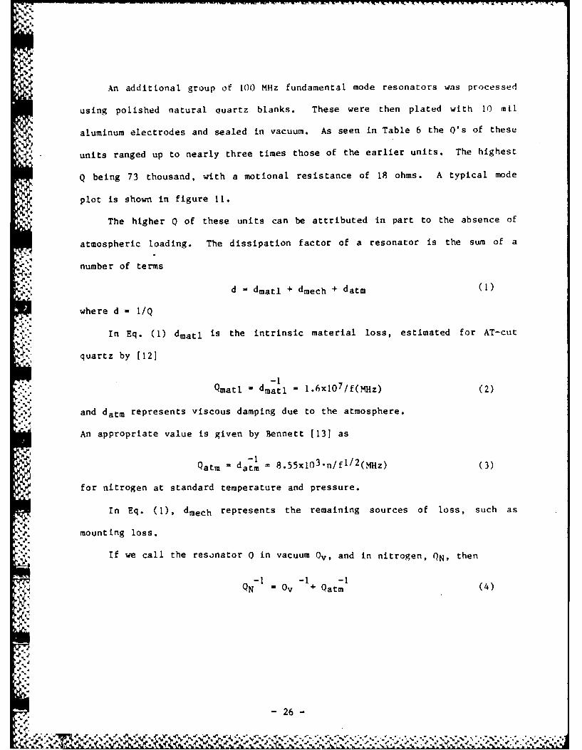
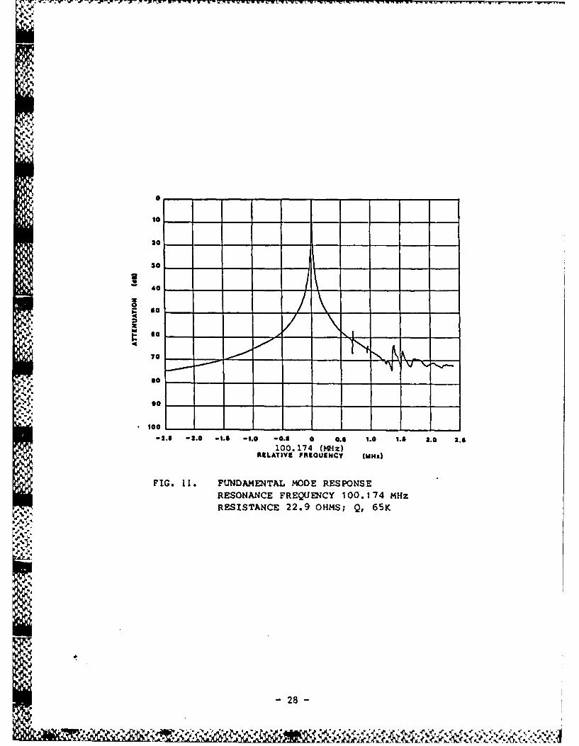
An additional group of 100 MHz fundamental mode resonators was processed
using polished natural quartz blanks. These were then plated with 10 mil
aluminum electrodes and sealed in vacuum. As seen in Table 6 the Q's of these
units ranged up to nearly three times those of the earlier units. The highest
Q being 73 thousand, with a motional resistance of 18 ohms. A typical mode
plot is shown in figure 11.
The higher 0 of these units can be attributed in part to the absence of
atmospheric loading. The dissipation factor of a resonator is the sum of a
number of terms
d = dmatl + dmech + datm
where d - I/Q
In Eq. (1) dmatl is the intrinsic material loss, estimated for AT-cut
quartz by [121
-1
p-." Qmatl = dmatl = 1.6xl0 7 /f(MHz) (2)
and datm represents viscous damping due to the atmosphere.
An appropriate value is given by Bennett [131 as
Qatm - datm 855x103 n/fl/2(MHz) (3)
for nitrogen at standard temperature and pressure.
In Eq. (1), dmech represents the remaining sources of loss, such as
mounting loss.
.4-. If we call the resonator 0 in vacuum 0v, and in nitrogen, QN, then
QN = Ov +Qatm (4)
- 26 -
-Acm
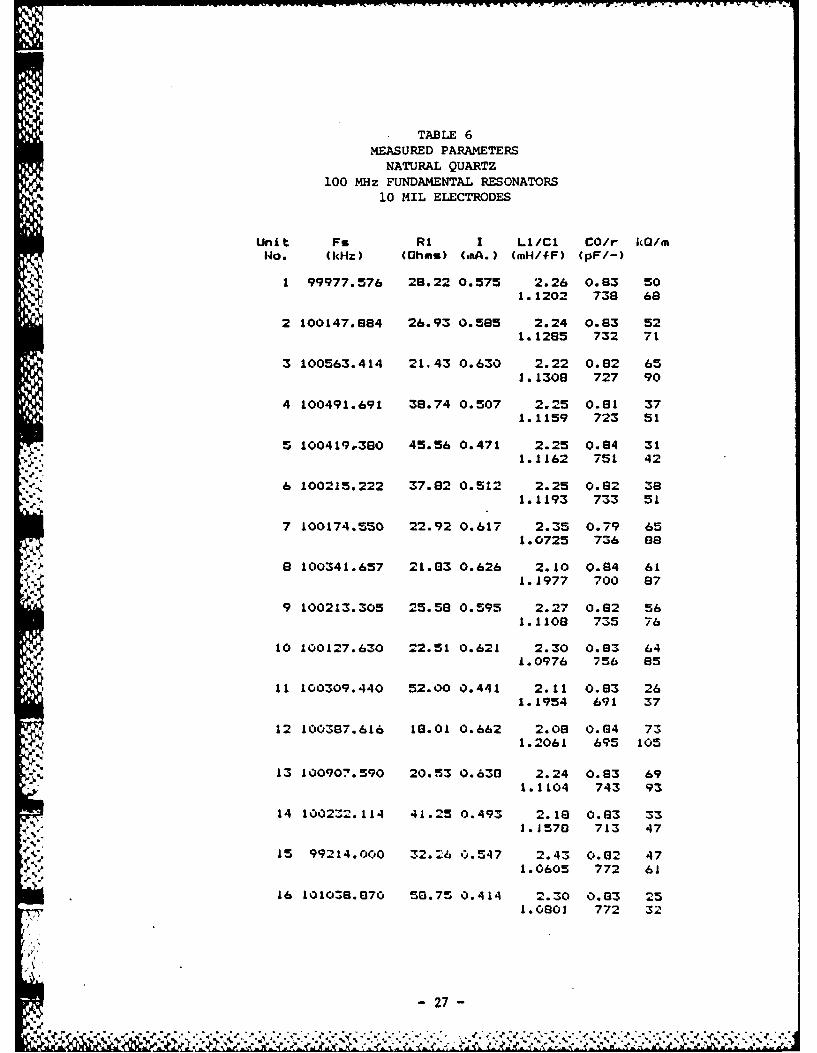
TABLE 6MEASURED PARAMETERS
NATURAL QUARTZ100 MHz FUNDAMENTAL RESONATORS
p. 10 MIL ELECTRODES
Unit Fs RI I LI/Cl CO/r kO/mNo. (kHz) (Ohms) (mA.) (mH/fF) (pF/-)
1 99977.576 28.22 0.575 2.26 0.83 501.1202 738 68
2 100147.984 26.93 0.595 2.24 0.93 521.1285 732 71
3 100563.414 21.43 0.630 2.22 0.82 651.1308 727 90
4 100491.691 39.74 0.507 2.25 0.91 371.1159 723 51
5 100419.380 45.56 0.471 2.25 0.94 31* 1.1162 751 42
6 100215.222 37.82 0.512 2.25 0.82 38- "1.1193 733 5L
7 100174.550 22.92 0.617 2.35 0.79 651.0725 736 89
e 100341.657 21.83 0.626 2.10 0.84 611.1977 700 87
9 100213.305 25.58 0.595 2.27 0.82 56
1.1108 735 76
10 100127.630 22.51 0.621 2.30 0.83 641.0976 756 85
11 100309.440 52.00 0.441 2.11 0.83 26
1.1954 691 37
12 100387.616 10.01 0.662 2.08 0.84 731.2061 695 105
13 100907.590 20.53 0.630 2.24 0.83 691.1104 743 93
14 100232.114 41.25 0.493 2.18 0.83 33J.1570 713 47
15 99214.000 32.26 0.547 2.43 0.02 471.0605 772 61
16 10108.870 5G.75 0.414 2.30 0.83 251.0803 772 32
S27
20
30
10
20 |l- - -~ -. -0. - O - . -. -.
10.00 (z
3.5_ - - -1. -6. -. -. -.-
, RLATIVE FREQUENCy (MHz)
FIG. 11. FUNDAMENTAL MODE RESPONSERESONANCE FREQUEN CY 100.1 74 MHzRESISTANCE 22,9 OHMS; Q, 65K
28
,- ~~- - - + ,,.~i.,, r
A few examples show that Qv can be considerably larger than QN,
especially when dmech is small, so that Qv approaches Qmatl. A "perfect"
" resonator at 100 MHz would have
lv - Qmatl - 1.6x10 5
while in dry nitrogen,
Qatm - 8.55x,04
and QN - 5.57xi04
Thus, the Q in vacuum in this ideal case is nearly three times the Q in4.
• : nitrogen.
To compare the Q's of Table 5 with those of Table 6, the highest 0 in
Table 5 was 29,000, measured in dry nitrogen. Using Eq. (4), the Q in vacuum
is estimated at 44,000, compared with 73,000 for the test resonator in Table4.
6.
Unless otherwise noted, the data reported in the balance of this report
is for resonators sealed in vacuum.
-.! A group of 100 MHz fundamental crystal resonators was fabricated using
swept quartz produced at PTI by the electrodiffusion process described in
.. Section 2.4. The results were very encouraging, with the swept cultured
quartz appearing nearly as good as the natural quartz in performance.
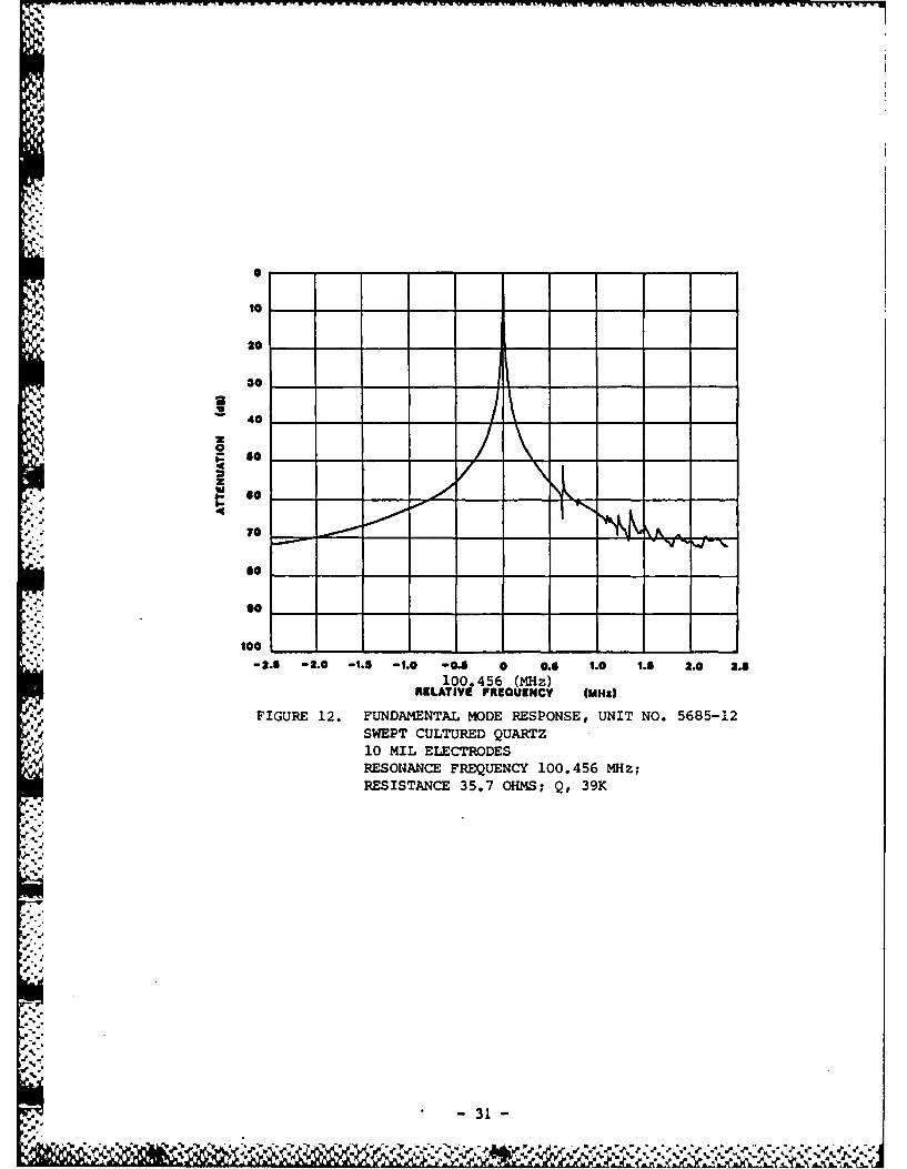
Table 7 shows the measured parameters for a group of 100 MHz fundamental
resonators fabricated out of swept cultured quartz, and figure 12 shows a
typical mode response of these units.
-29
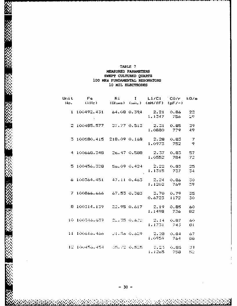
TABLE 7
MEASURED PARAMETERSA "SWEPT CULTURED QUARTZ
100 MHz FUNDAMENTAL RESONATORS10 MIL ELECTRODES
Urlit Fs Rl I L1/Cl CO/r k./nHo. (IdIz) (Ohims) (Oii. ) (mH/fF) (pF/-
1 100',492.431 64.08 0.39.4 2.21 0.86 221. J 347 756 "-l
I= 00485.577 Z*;.77 0.51Z 2.3--1 0.85 39. )886 07 7 4 9
z3166580.415 218.09 0. 168 2.28 o.(33 7-. %. ., 1. 09g73 75 9
4 100660.7-48 26. 4 7 0 .58~08 2. 37 0.G3 572 . 0552 784 "7;
5 100456. 328 5.09 C',.424 2.22 0.83 251. 1315 737 34
6 100364.451 47.11 0. 463 2. 24 0.86 ..J.1202 769 3.9
7 106666. 666 67.53 0.383 3.70 0.79 350. 6723 1172 30
8 100314. 139 22.995 6.617 2.19 0.85 601. 149 7 736 82
'1 1 ", 07',-,. ,5k7 2 .3 . 6 ': 2.1 0 '. G87 60I I. 173 ;.1 7 4 81
I 1IOC6/ . IE, .2. 0 . 62-,q '= 2. 28G 0. G4 67
i. 55; 764 08
,.#., I. 1 265 754 51I.
- 30 -
10
to
30
04
,,.. 4- ° /',70L
Jso
0K.'.'-*10
.. so
-2.5 -2.0 -1.s -1.0 -0. 0 0.5 1.0 1.8 2.0 2.5100.456 (MHz)
RELATIVE FROUENCY (MHz)
FIGURE 12. FUNDAMENTAL MODE RESPONSE, UNIT NO. 5685-12SWEPT CULTURED QUARTZ10 MIL ELECTRODESRESONANCE FREQUENCY 100.456 MHz;RESISTANCE 35.7 OHMS; Q, 39K
..V" "3
'
,> ' - 31 -* ,,, .ha+ + +, +++ + +,,,,+ + + .+,,.+.+++ ,+ .+,.,, .+ ,,.. +., .+ .. , ,
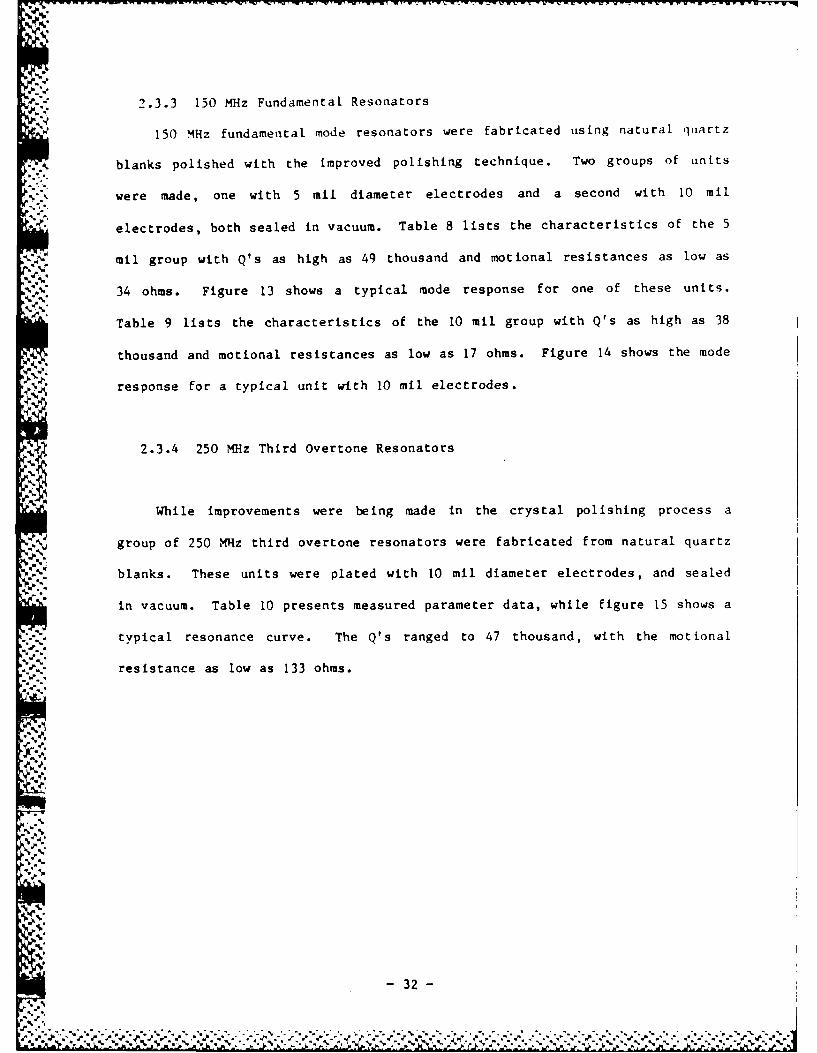
2.3.3 150 MHz Fundamental Resonators
150 MHz fundamental mode resonators were fabricated using natural quartz
blanks polished with the improved polishing technique. Two groups of units
were made, one with 5 mil diameter electrodes and a second with 10 mil
*electrodes, both sealed in vacuum. Table 8 lists the characteristics of the 5
mil group with Q's as high as 49 thousand and motional resistances as low as
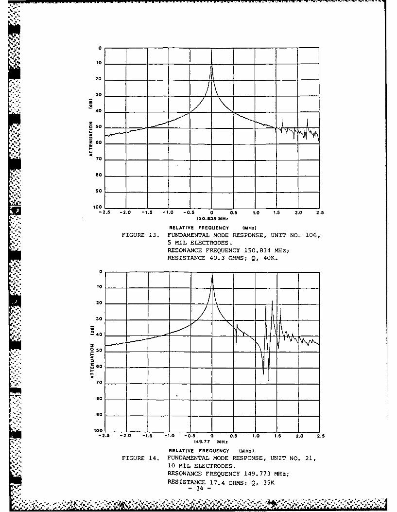
34 ohms. Figure 13 shows a typical mode response for one of these units.
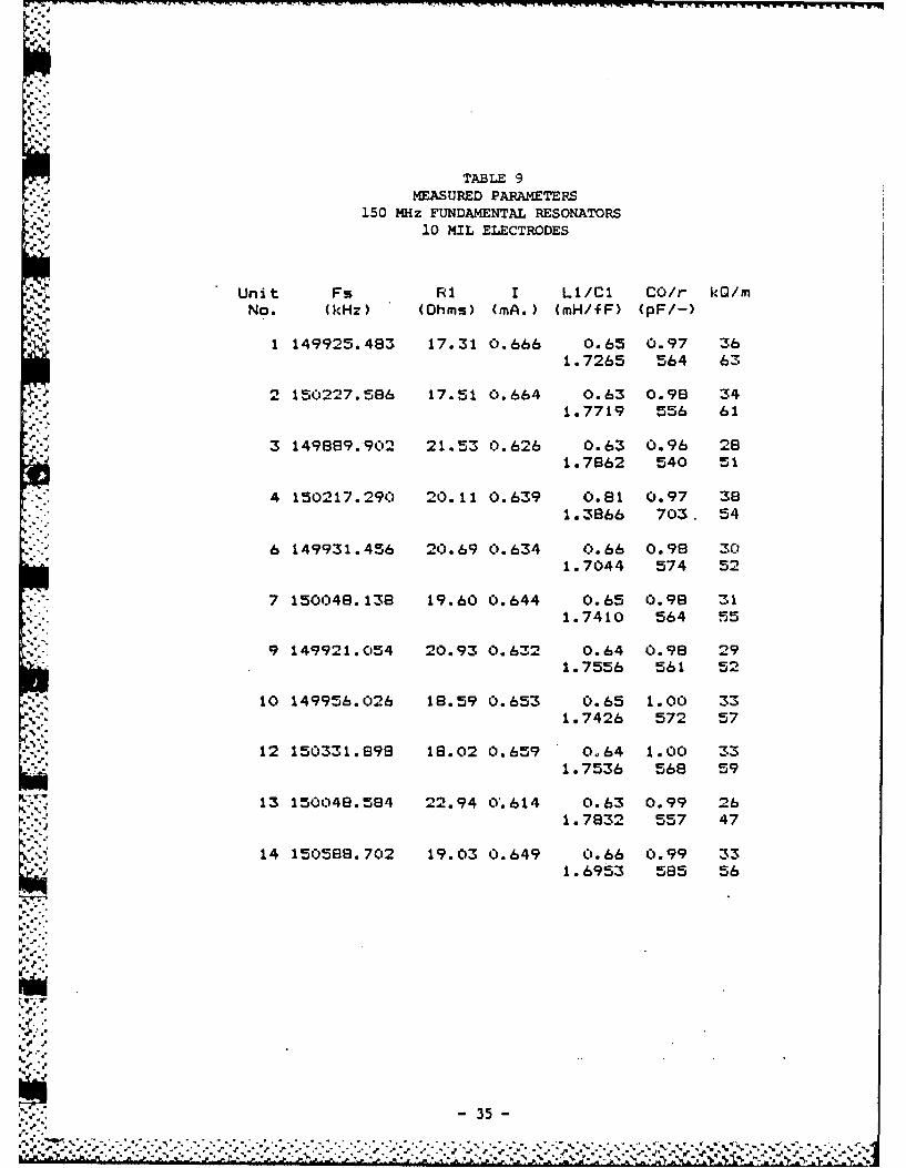
Table 9 lists the characteristics of the 10 mil group with Q's as high as 38
thousand and motional resistances as low as 17 ohms. Figure 14 shows the mode
response for a typical unit with 10 mil electrodes.
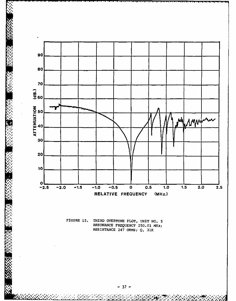
2.3.4 250 MHz Third Overtone Resonators
While improvements were being made in the crystal polishing process a
group of 250 MHz third overtone resonators were fabricated from natural quartz
blanks. These units were plated with 10 mil diameter electrodes, and sealed
in vacuum. Table 10 presents measured parameter data, while figure 15 shows a
typical resonance curve. The Q's ranged to 47 thousand, with the motional
resistance as low as 133 ohms.
ha
is
5%
- 32-
~. P
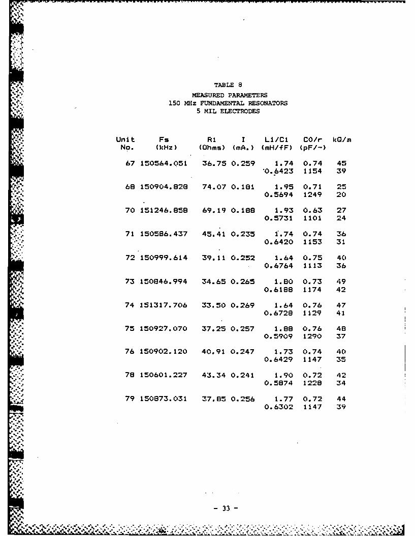
TABLE 8
MEASURED PARAMETERS150 MHz FUNDAMENTAL RESONATORS
5 MIL ELECTRODES
Unit Fs R1 I LI/Cl CO/r kQ/mNo. (kHz) (Ohms) (mA.) (mH/fF) (pF/-)
67 150564.051 36.75 0.259 1.74 0.74 45"0.6423 1154 39
68 150904.828 74.07 0.181 1.95 0.71 250.5694 1249 20
70 151246.858 69.19 0.188 1.93 0.63 270.5731 1101 24
71 150586.437 45.41 0.235 1.74 0.74 360.6420 1153 31
72 150999.614 39.11 0.252 1.64 0.75 400.6764 1113 36
73 150846.994 34.65 0.265 1.80 0.73 49
0.6188 1174 42
74 151317.706 33.50 0.269 1.64 0.76 470.6728 1129 41
75 150927.070 37.25 0.257 1.88 0.76 480. 5909 1290 37
76 150902.120 40.91 0.247 1.73 0.74 400.6429 1147 35
78 150601.227 43.34 0.241 1.90 0.72 420.5874 1228 34
79 150873.031 37.85 0.256 1.77 0.72 440.6302 1147 39
.
- 33-
sd%
20__
30 __
0
40
w20 __ 50 ~ __ _ _ _
70 _ _ - -_ _ _
-2.5 -2.0 -1.5 -1.0 -0.5 0 0.5 1.0 1.5 2.0 2.5150.835 MHz
RELATIVE FREQUIENCY (MHZ)
FIGURE 13. FUNDAMENTAL MODE RESPONSE, UNIT NO. 106,5 MIL ELECTRODES.
RESONANCE FREQUENCY 150.834 MHz;RESISTANCE 40.3 OHMS; Q, 40K.
10____ __
20
30 __ _-
.240 - -NA.
20
Z 60 -
80 ___
-2.5 -2.0 -1.5 -1.0 -0.5 0 0.5 1.0 1.5 2.0 2.5
RELATIVE FREQUENCY (MHz)FIGURE 14. FUNDAM"ENTAL MODE RESPONSE, UNIT NO. 21,
10 MIL ELECTRODES.RESONANCE FREQUENCY 149.773 MHz;RESISTANCE 17.4 OHMS; Q, 35K
.d- 34 -
1 m I w-
TABLE 9MEASURED PARAMETERS
150 M~Uz FUNDAMENTAL RESONATORS10 MIL ELECTRODES
Unit Fs RI I Li/Cl CO/r kQ/mNo. (kHz) (Ohms) (mA.) (mH/fF) (pF/-)
1 149925.483 17.31 0.666 0.65 0.97 361.7265 564 63
2 150227.586 17.51 0.664 0.63 0.98 341.7719 556 61
3 149889.902 21.53 0.626 0.63 0.96 281.7862 540 51
4 150217.290 20.11 0.639 0.81 0.97 381.3866 703. 54
6 149931.456 20.69 0.634 0.66 0.98 301.7044 574 52
7 150048.138 19.60 0.644 0.65 0.98 311.7410 564 55
9 149921.054 20.93 0.632 0.64 0.98 291.7556 561 52
10 149956.026 18.59 0.653 0.65 1.00 331.7426 572 57
12 150331.898 18.02 0.659 0.64 1.00 331.7536 568 59
13 150048.584 22.94 0'.614 0.63 0.99 261.7832 557 47
14 150588.702 19.03 0.649 0.66 0.99 33
1.6953 585 56
. -.S.i*
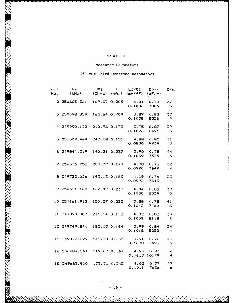
TABLE 10
Measured Parameters
250 MHz Third Overtone Resonators
Unit Fs RI I LI/Cl CO/r ko/InNo. (kHz) (Ohms) (mA.) (mH/fF) (pF/-)
2 250603.361 169.37 0.205 4.01 0.78 370.1006 7806 5
3 25039e.829 165.64 0.209 3.69 0.88 370.1038 8526 4
4 249990.122 210.96 0.172 3.95 0.67 29
0.1026 8491 3
5 250009.469 247.08 0.151 4.8 0.82 310.0830 9934 3
6 249844.319 140.21 0.237 3.90 0.78 440.1039 7535 6
7 250575.752 200.79 0. 179 4.08 0.76 :20.0990 7649 4
8 249732. 026 193. 13 0. 185 4.09 0. 76 :3
0.0993 7643 4
9 25 0321.100 162.09 0.212 4.04 0.85 390.1000 8534 5
10 25"161.913 150.27 0.225 3.88 0.78 410.1043 7460 5
11 249890.067 211.14 0.172 4. 02 0.82 300. 1009 6116 4
12 249749.840 182.03 0.194 3.99 0.834 340. 1018 8252 4
15 249672.629 141.16 0.235 3.91 0.78 430. 1036 7493 6
16 25,'6689.261 219.07 0.167 4.95 0.63 360.0813 10179 4
18 249663.900 133.31 0.245 4. 02 0.77 470.1011 7656 6
- 36 -
90 ___
80 - __
=70'
60
%Z
0 5 0
1 A.AZL" 40
30 -
20
10
-2.5 -2.0 -1.5 -1.0 -0.5 0 0.5 1.0 1.5 2.0 2.5
RELATIVE FREQUENCY (MHz.)
FIGURE 15. THIRD OVERTONE PLOT, UNIT NO. 5~RESONANCE FREQUENCY 250.01 MHz;RESISTANCE 247 OHMS; Q, 31K
El.
44 " - " •" "" , " " " " """ """" "-" "." ."" "-" ' """, ",",' '" ".",. , ." "," -".- 3,7--
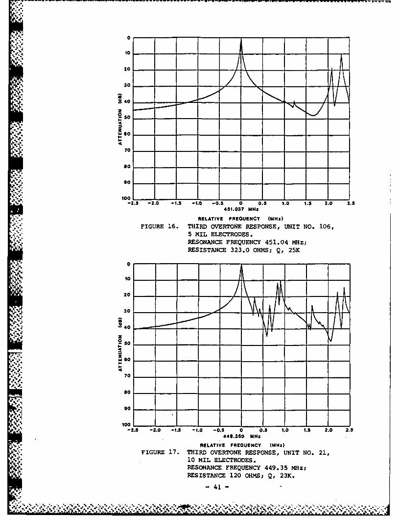
2.3.5 450 MHz Third Overtone Resonators
Using the improved polishing process, two groups of 450 MHz third over-
tone resonators were fabricated from natural quartz blanks. One group was
plated with 5 mil diameter electrodes and a second group was plated with 10
mil diameter electrodes, both groups were sealed in vacuum. Characteristics
of representive units are shown in Tables 11 and 12. For the 5 mil electrodes
the Q's ranged as high as 27 thousand with the motional resistances as low as
288 ohms. The Q's for the 10 mil group also ranged as high as 27 thousand
with motional resistances as low as 100 ohms. Typical mode plots for these
two groups are shown in figures 16 and 17.
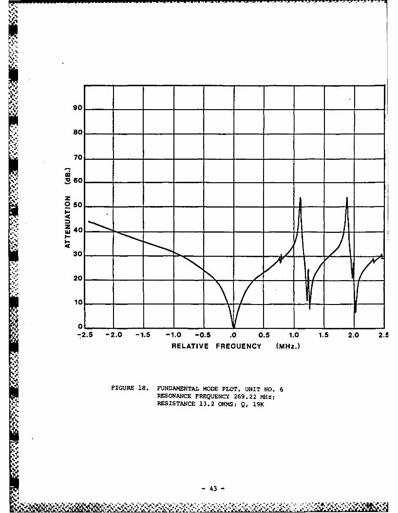
2.3.6 UHF Fundamental Resonators
In a brief experiment a small 'group of surplus blanks from another
project were etched to a fundamental frequency of approximately 270 MHz,
plated with 10 mil aluminum electrodes, and sealed in vacuum. No attempt was
made to achieve a uniform frequency. As indicated in Table 13, Q's ranged
from 9 thousand to 30 thousand, while mode resistances were between 13 and 30
ohms. Figure 18 is a mode plot for one of the fundamental mode units
acceptable unwanted mode levels.
A second group of natural blanks was etched to fundamental frequencies in
the range of 250 MHz. These crystals were fabricated into resonators using 5
mil electrodes instead of 10 mil, and were also sealed in vacuum. The results
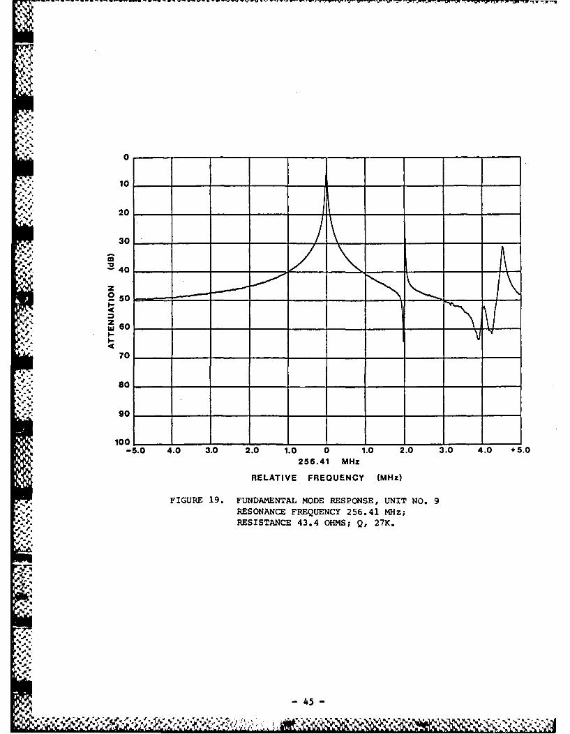
are shown in Table 14 and a mode plot is given in figure 19. Q's ranged from
[4 .
-38..
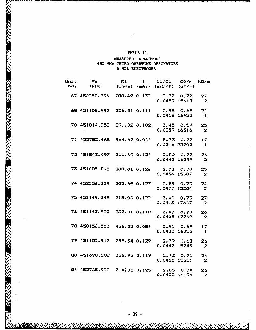
TABLE 11
MEASURED PARAM4ETERS450 MHz THIRD OVERTONE RESONATORS
5 MIL ELECTRODES
Unit Fs RI I Li/Cl CO/r kQ/mNo. (kHz) (Ohms) (mA.) (mH/fF) (pF/-)
67 450258.796 288.42 0.133 2.72 0.72 270.0459 15618 2
68 451108.993 356.51 0.111 2.98 0.69 240.0418 16453 1
70 451614.253 391.02 0.102 3.45 0.59 250.0359 16516 2
71 452783.468 964.62 0.044 5.73 0.72 170.0216 33202 1
72 451543.097 311.69 0.124 2.80 0.72 260.0443 16249 2
73 451065.895 306.01 0.126 2.73 0.70 250.0456 15307 2
74 452556.329 305.69 0.127 2.59 0.73 240.0477 15304 2
75 451149.346 318.04 0.122 3.00 0.73 27
0.0415 17647 2
76 451143.983 332.01 0.118 3.07 0.70 26
0.0405 17249 2
76 450156.550 486.02 0.064 2.91 0.69 170.0430 16055 1
79 451152.917 299.34 0.129 2.79 0.68 26
0.0447 15245 2
80 451698.208 326.92 0.119 2.73 0.71 240.0455 15551 2
e4 452765.978 310:05 0.125 2.85 0.70 26
0.0433 16194 2
-39 -
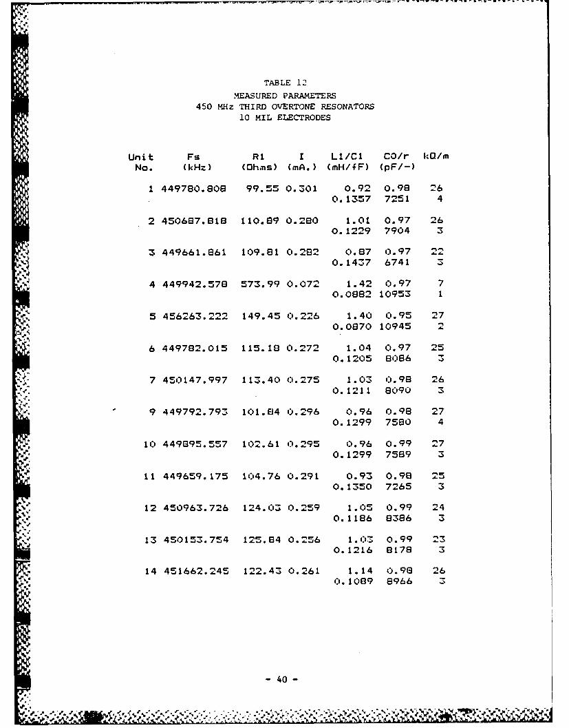
TABLE 12
MEASURED PARAMETERS450 MHz THIRD OVERTONE RESONATORS
10 MIL ELECTRODES
Unit Fs RI I LI/Cl CO/r kQ/mNo. (kHz) (Ohims) (mA.) (mH/fF) (pF/-)
1 449780.608 99.55 0.301 0.92 0.98 260.1357 7251 4
2 450687.616 110.89 0.260 1.01 0.97 260.1229 7904 3
3 449661.861 109.81 0.282 0.87 0.97 220. 1437 6741 3
4 449942.578 573.99 0.072 1.42 0.97 70.0882 10953 1
5 456263.222 149.45 0.226 1.40 0.95 270.0870 10945 2
6 449782.015 115.10 0.272 1.04 0.97 250. 1205 63086 3
7 450147.997 113.40 0..275 1.03 C0.96 260.1211 63090 3
9 449792. 793 101.84 o.296 0.96 0.98 270.1299 7580 4
10 449895.557 102.61 0.295 0.96 0.99 270.1299 7589 3
11 449659.175 104.76 0.291 0.93 0.98 250.1350 7265 3
12 450963.726 124.03 0.259 1. 05 0.99 240.1186 6386 3
13 450153.754 125.84 0.256 1.03 0.99 230.1216 8178 3
14 451662.245 122.43 0.261 1.14 0.98 26(0. 10G9 8966 3
- 40 -
Fi.
*%. %
0~~~~W V -- - - - - - - - - - - -
0
40
* 20
30
, 40
A Z
0-6
80
go
100...-2.5 -2.0 -1.5 -1.0 -0.5 0 0.5 1.0 1.5 2.0 2.5
451.037 MHz
RELATIVE FREQUENCY (MHz)
FIGURE 16. THIRD OVERTONE RESPONSE, UNIT NO. 106,5 MIL ELECTRODES.RESONANCE FREQUENCY 451.04 MHz;RESISTANCE 323.0 OHMS; Q, 25K
10, - - - , - -
0-10
2
' 4_ i0MLEECRDS
REITAC 1soHM;Q,2
"5 -' . ...
70
5so
90
100-2.5 -2.0 -t.5 -1.0 -0.5 0 0.5 1.0 1.5 2.0 2.5
449.350 MHz
RELATIVE FREQUENCY WHO)FIGURE 17. THIRD OVERTONE RESPONSE, UNIT NO. 21,
"S.' 10 MIL ELECTRODES.RESONANCE FREQUENCY 449.35 MHz;RESISTANCE 120 OHMS; Q, 23K.
-41-
-. % :. ~ ~ ~ ~ .,a 5 . S .-. ~
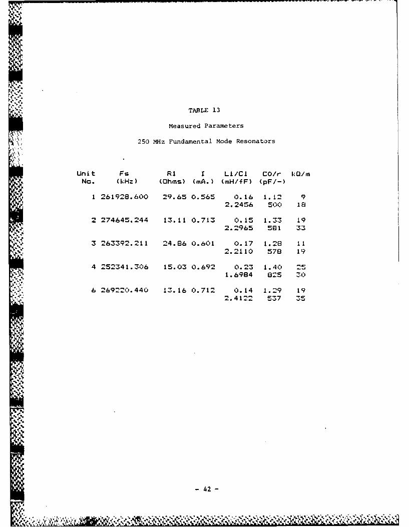
TABLE 13
Measured Parameters
250 MHz Fundamental Mode Resonators
Unit Fs RI I LI/Cl CO/r 10r/mNo. (kHz) (Ohms) (mA.) (mH/fF) (pF/-)
1 261928.600 29.65 0.565 0.16 1.12 92.2456 5C0 18
2 274645.244 13.11 0.713 0.15 1.33 192.2965 581 33
3 263392.211 24.86 o.601 0.17 1.28 112.2110 578 19
4 252341 .306 15.03 0.692 0.23 1. 4 251.6984 825 30
6 2692:)0.440 13.16 0.712 0.14 1.29 19
2.4122 537 35
S42 -
- ---- ------- ~ -
,6R
90 _ _ _ _ _ _ _ _ _
'. 80______________
870 -_ _ _ _ _ _ _ _ _ _ _ _
. 60
Z250 -
Zw40
34 0 00__
/,/,. -::2 0
30
-2.5 -2.0 -1.5 -1.0 -0.5 .0 0.5 1.0 1.5 2.0 2A
RELATIVE FREQUENCY (MHz.)
FIGURE 18. FUNDAMENTAL MODE PLOT, UNIT NO. 6RESONANCE FREQUENCY 269.22 MHz;RESISTANCE 13.2 OHMS; Q, 19K
- 43

TABLE 14,
MEASURED PARAMETERS
250 MHz FUNDAMENTAL RESONATORS5 MIL ELECTRODES
Unit Fs RI I Li/Cl CO/r kG/mNo. (kHz) (Ohms) (mA.) (mH/fF) (pF/-)
9 256409.894 43.36 0.482 0.72 0.98 270.5344 1632 15
10 245383.418 66.10 0.381 0.81 0.77 160.5197 1487 1-
12 244842.906 50.31 0.449 0.66 o.77 200.6400 1210 17
,v% 13 246772.969 37.72 o.513 0.68 0.75 280.6131 1226 23
15 244889.166 37.19 0.516 0.73 0.73 300.5792 1266 24
16 246710.000 94.75 0.311 0.86 0.74 140. 4625 1524 9
17 245651.796 60.99 0.405 0.82 0.77 210.5093 1519 14
18 246728.707 61.67 0.403 0.812 0.75 210.5087 1477 14
67 23424 1.603 63.03 0.336 0.72 0.74 13
0.6432 1145 11
68 250227.323 42.31 0.487 0.73 0.71 270.5573 1267 21
78 256307.014 59.60 0.411 0.54 0.79 150.7181 1094 13
i44
- 44 -
* .i - • " -s": * - • " % % " % % " . % " .'%."." " " " . .% m % % " -% " -,." "
o010
•440
";.-.<
250
- 70
'- '-"80
-5.0 4.0 3.0 2.0 1.0 0 1.0 2.0 3.0 4.0 + 5.0256.41 MHz
RELATIVE FREQUENCY (MHz)
- FIGURE 19. FUNDAMENTAL MODE RESPONSE, UNIT NO. 9.. . RESONANCE FREQUENCY 256.41 MHz;,J'. ~RESIrSTANC"E 43.4 OHMS.; Q, 27K.
. ,,..4
;--
- 45 -
14 thousand to 30 thousand, slightly higher than the units made with 10 mil
electrodes. Comparing these units with the third overtone units shown earlier
% in Table 10, it is seen that, as would be expected, the resistance and 0 of
the fundamental mode devices are both lower than for the third overtone units.
The 250 MHz third overtone and 250 MHz fundamental units illustrate a
fundamental design trade-off: for a given frequency and electrode
configuration, the motional impedance level is proportional to the cube of the9.
overtone. Thus the motional inductance of the third overtone 250 MHz units is
approximately 27 times that of the 250 MHz fundamental ones. However, and
typically, the Q of the fundamental units is less than that of the overtone
units so that motional resistances are in a ratio of very roughly I to 10, and
of course the capacitance ratio of the fundamental is much lower than for the
third overtone - in this instance by a factor of 12 or 15.
In general, for oscillator applications, fundamental mode resonators are
favored where ease of frequency "pulling" is important; e.g., temperature-
compensated and voltage-controlled oscillators. In some precision oscillator
applications, however, just the opposite is wanted in order to minimize the
effects of oscillator circuitry on frequency, and hence on aging. The use of
overtones also favors good resonator aging. Moreover, for low phase noise and
good short-term stability it is desirable to maximize Q -- specifically, the
loaded 0 of the resonator in the oscillator circuit. The use of very high
[- ' overtones, even in precision oscillators, is, however, limited by practical
impedance level consideration and the need for enough pullability to correct
for inevitable manufacturing tolerances in resonator frequency.
i - 46-
6% °
Pe W.-
To further explore the possibility of producing UHF range fundamental
resonators, two groups of blanks were etched to approximately 350-525 MHz on
the fundamental. These units were plated with 5 mil electrodes and sealed in
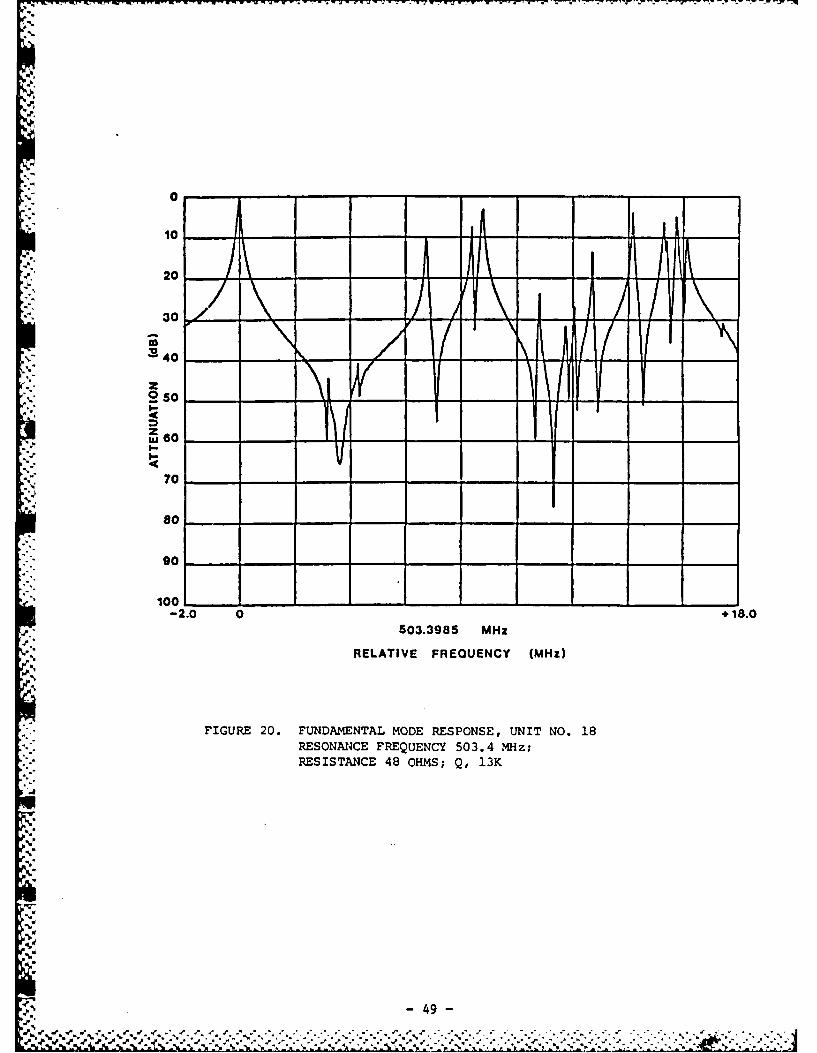
vacuum. Their characteristics are shown in Tables 15 and 16. Figure 20 shows
a typical fundamental mode response for one of these units. Q's for
resonators around 500 MHz ranged up to 13 thousand and mode resistances were
as low as 48 ohms. It should be noted that no attempt was made to trim all
the blanks to any particular frequency. A thickness difference between blanks
of I micron at 30 MHz represents a frequency difference of 550 kHz, while the
same I micron difference at 500 MHz represents a frequency difference of 215
MHz. Thus a large variation in frequency between individual units within each
UHF group is not surprising.
'Encouraged by these preliminary results, two more groups of natural
quartz blanks were etched to UHF fundamental frequencies.
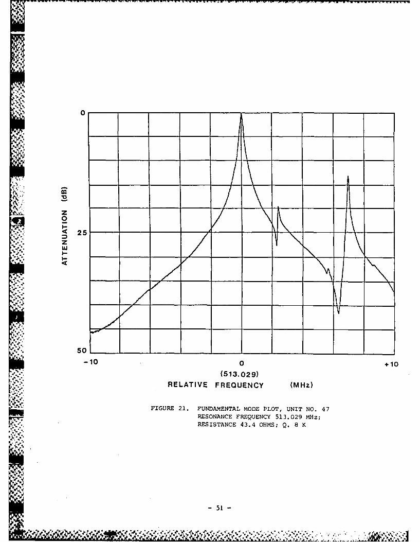
The first of these two groups was plated with 5 mil electrodes and sealed
in vacuum. The resulting resonators ranged in frequency from approximately
440 MHz to 674 MHz, as seen in Table 17. A mode plot of one of the higher
units is shown in figure 21.
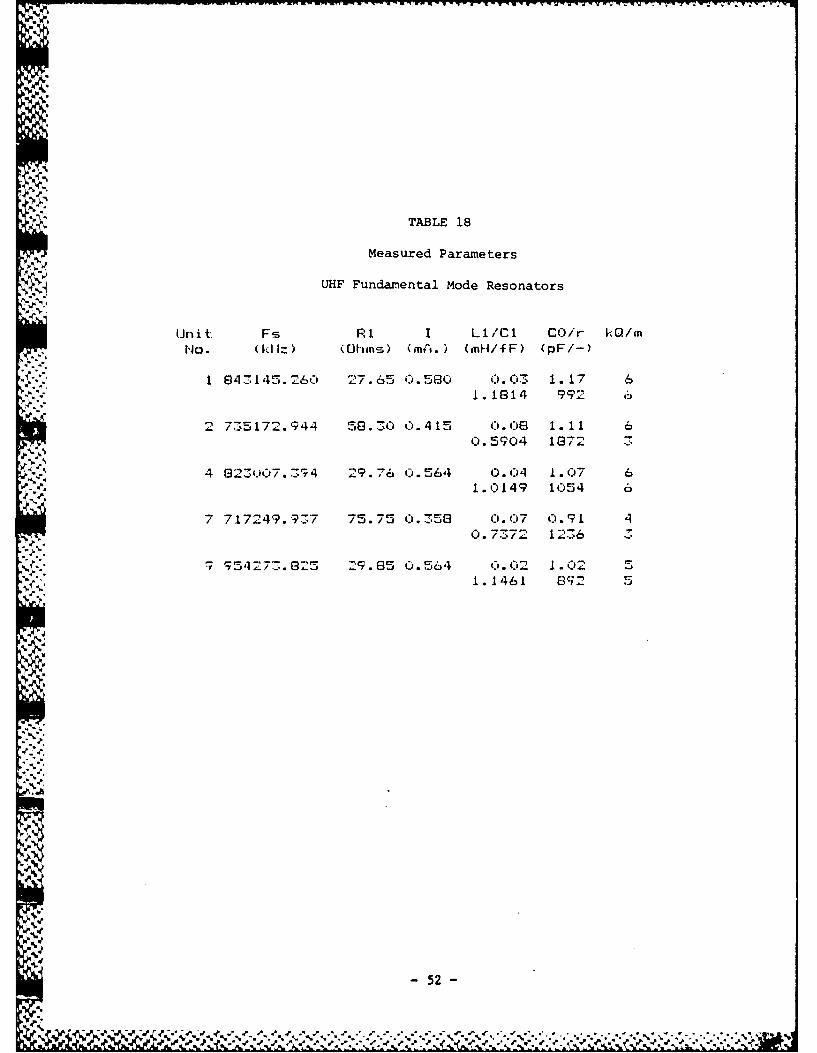
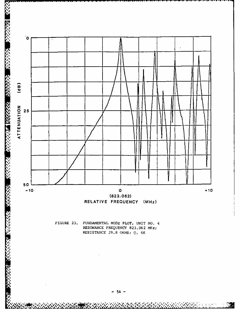
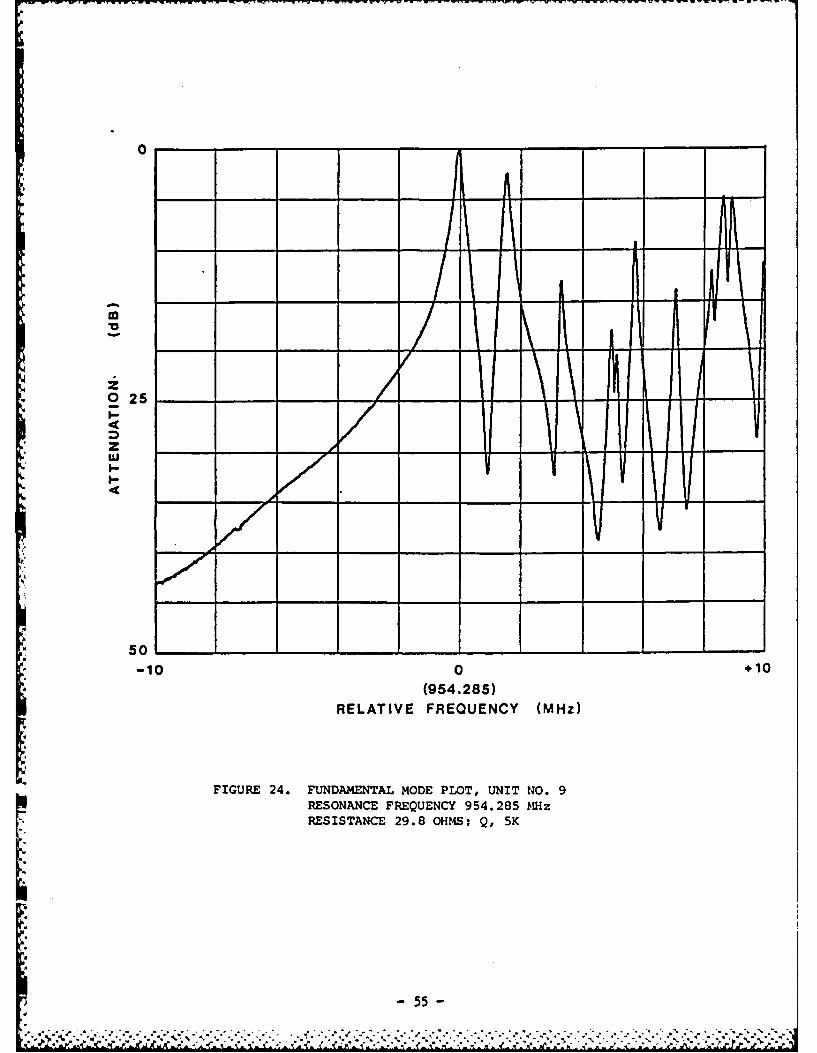
The second group of blanks was etched, plated with 2.5 mil electrodes,
and sealed in vacuum. The fundamental frequencies of this group ranged from
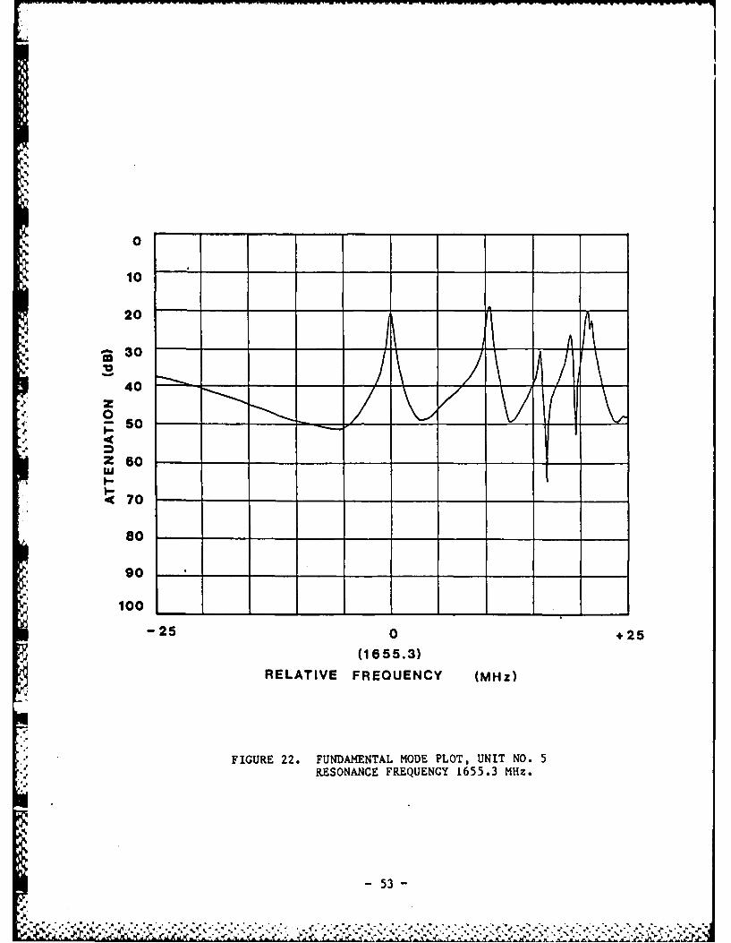
SI approximately 700 MHz to over 1.6 GHz. Table 18 shows a portion of these
resonators, with the highest being 954 MHz. The automatic test equipment used
for these measurements has an upper frequency limit of 1000 MHz. Unit #5 was
measured on a manual system, and showed a frequency of 1,655 MHz. Figure 22
shows a mode plot of this unit, while figures 23 and 24 show mode plots of
an 823 MHz and an 954 MHz resonator respectively.
- 47 -
oe -eV ~ :C:~*.*::-
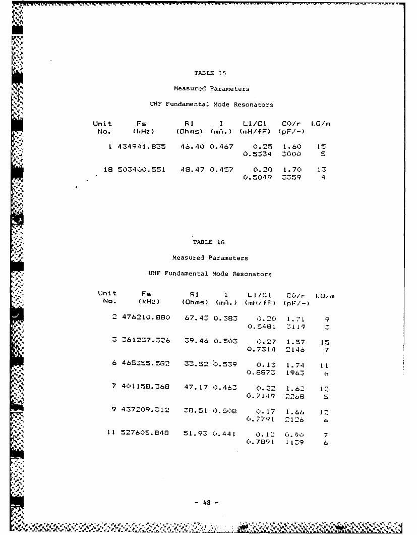
TABLE 15
Measured Parameters
UHF Fundamental Mode Resonators
Unit Fs R1 I Li/Cl C)/r kQ/mNo. (Oklz) (Ohms) (inti. )' (ml-l/f F) (pF/-)
I 434941.635 46.40 0.467 0.25 1.60 150. 5334 3000 5
18 503400.551 46.47 0.457 0.20 1.70 130.5049 3359 4
. .',.
*: TABLE 16
Measured Parameters
UHF Fundamental Mode Resonators
Unit Fs RI I LI/Cl CO/r kO/ ,inNo. (kHz) (Ohmis) (nA. ) (ofl/ FF) (pF:/-)
2 476210.880 67.4Z 0.38 C).20 1.71.40.5 461 3119 5
-. 'I 1 A d .~ ... * O"'-.5Z -; 36 1237..2 6 Z39. 46 0. 503S (:.27 1 .5r-7 15
0.7314 2146 7
6 465355.562 35.52 0.539 C). 13 1.74 110.8873 196S 6
7 401150.368 47.17 0.46Z C :.22 1.62 120.7149 2268
9 437209.512 6 I51 (1.56 0. 17 1 66 120. 7791 2126
11 527605.848 ,1. 9 0.441 0. 12 C.7f. 7C). 7891 115 9 6
,4'A,.
~- 48 -
',
4~40
-. 90
-. 0 --
103- - -
.. 0
FIGUR 20 UDMNA OEREPNE NTN.1
.9
--2. - - - - -. 0-
'4.°
.'.:...
.4
." I,.. aU.I,,I" .. '. ,.-"., . ". " . ". '.. "<"...80 ' " '. ". .'_"._,,..- . .- -. .'-.. .-. l i" . ." - -..-
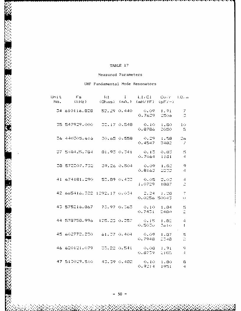
TABLE 17
Measured Parameters
- UHF Fundamental Mode Resonators
Unit F5 Fi I L.1/CI C.i, I. C!,No. (klz) (OhI-ns) (nit.) (mi IfF) (pFi'--)
34 6 10116. 829 ,5. 29 o. 44C c. c9 . 7Q. 7629 2506
... 5,, 5479q .0 6 . 2l.l' . . 1 7 0. 541 0 ). I(-) I GO I3
C. 8786 2C5) 0
.,,,, 36 4403-'. 6 u c.5 0.558 0.29 1 58 .. 4547 _-,E82 7
,,, 51-'2.76-4 91.93 u.-41 0. 1 : C.0: 5"'- ~ ~ .I._ .. 9- 0.
6. 7664 1 10 E1 '1
S."39 5722(:)7.7_'/. 39.26 0. 504 0.0C .]2 9
B .16. 2 7-2 4""41 674I1F 2. 9(.-) 57-.09 ('P.47-: C.0 2.(,12 .1
1. 729 1 38 7 2
42 6o5416.722 12'?2.17 c,.'4 .2q 1. 20 7a - . - ... jC € (
47_ 575216.867 72.97 0.6.'6,. C). It 1.94 5
S4. 74. 240l:,
44 573750.996 125.2: 0.255 c. 1i 1.2
V 45 602772.230 61.37 0.27-4 Ci. 9 1.37 5
C'. 79-10 38
46 62 1:2.Ci79 3'-7.. 22 541 019 1. 9 1
47 51-',) . 5 L 3.39 t'. 102 ' . .' 1.00 9Co. 921 195 ,
- 50 -
3- Ja "'
0
jm
LZ
0I-.
' 25. Z
_50
-10 0 +10
(513.029)RELATIVE FREQUENCY (MHz)
FIGURE 21. FUNDAMENTAL MODE PLOT, UNIT NO. 47
RESONANCE FREQUENCY 513.029 MHz;RESISTANCE 43.4 OHMS; Q. 8 K
- 51 -
b -. • ¢ I . q . ,. q a "- i ... € • -. -
i TABLE 18
Measured Parameters
UHF Fundamental Mode Resonators
Unit Fs RI I LI/Cl CO/r k/m_, ::NO. (1l-1-1 ) (Ohms) (mA. ) (mnH/f F) (pF/-)
1 8A3145.260 27.65 0.5801 0.03 1.17 61.1814 992 ,6
2 735172.944 58.30 0.415 0].08 1.11 60.5904 1872 7
4 8230 7.3 74 29.76 0.564 0. 04 1.07 61.0149 1054 6
7 717249.937 75.75 0.358 0.07 y.L A0.7372 1236
7 315427.825 .29.85 0. 564 0.02 1.02 51.1461 82 5
95
-------------
0
10
20
~30
wo40
Z0 __u
50
C 70 - __ __
s0-o__ - _ _
90__ ___ _ __ __ _
-25 0 +25(1655.3)
RELATIVE FREQUENCY (MHz)
FIGURE 22. FUNDAMENTAL MODE PLOT, UNIT NO. 5RESONANCE FREQUENCY 1655.3 MHz.
-53 -
**13
0 025_- ;-
50 2
-10 0 +10(823.062)
RELATIVE FREQUENCY (MHz)
FIGURE 23. FUNDAMENTAL MODE PLOT, UNIT NO. 4RESONANCE FREQUENCY 823.062 MHz;
RESISTANCE 29.8 OHMS; Q, 6K
.554
A- 54A
,.
S....X A! / !I
0
* 025 0__
-10+1
(9425
RESONACE FREUENC285.8) M
RESISTANCE 29.8 OHMS; Q, 5K
-55-
L"" , rVr -I -9 $_ W -71 -
These higher frequency resonators exhibit larger than normal spurious
mode responses. The electrode dimensions and mass loading used for these
crystals were not optimum for the frequency. Different techniques from those".
currently in use would have to be developed to achieve optimum electrode
configurations at frequencies in the gigahertz range. The highest
unelectroded blank frequency measured was over 1.7 GHz. The membrane
thickness required to achieve this frequency is just under 1.0 microns. The
fact that these blanks survived all the processing steps necessary to produce
finished units testifies to the inherent strength of the quartz membrane.
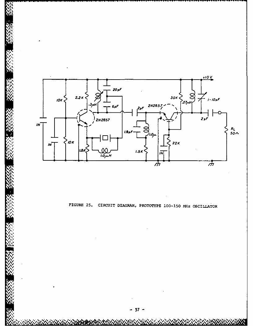
2.3.7 Oscillator Circuit
To demonstrate the feasibility of using the VHF units fabrIcated under
this program, a simple bread-board 100 MHz crystal oscillator was constructed,
figure 25. The circuit was then built in prototype form using standard
printed-circuit construction. It consists of a single-transistor oscillator
stage followed by an output buffer, and will function to 150 MHz.
-56-
'.'
+IO
*1
20or
•10K 2.2K 30K .2714H - pF
6pF 2pF 2N2857-- N\
IN - 1 2N2857 %
I.p 1..850
"4/4..I I.O/M..
4%
FIGURE 25. CIRCUIT DIAGRAM, PROTOTYPE 100-150 MHz OSCILLATOR
.57
'I.
, .
~- 57 -
2.4 Electrodiffusion of Ouartz
It had previously been found that all attempts made at producing VHF
resonators by wet chemical etching of cultured quartz resulted in severely
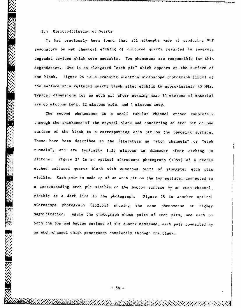
degraded devices which were unusable. Two phenomena are responsible for this
degradation. One is an elongated "etch pit" which appears on the surface of
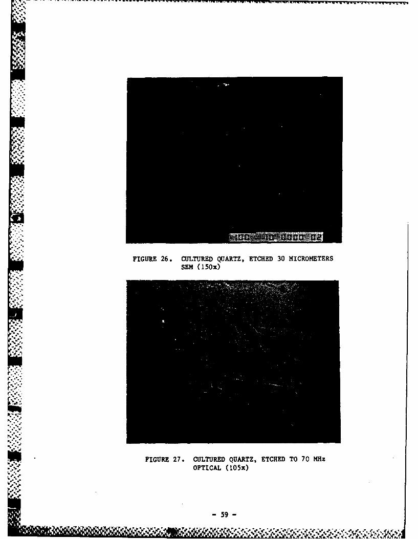
the blank. Figure 26 is a scanning electron microscope photograph (150x) of
the surface of a cultured quartz blank after etching to approximately 70 MHz.
Typical dimensions for an etch pit after etching away 30 microns of material
are 65 microns long, 22 microns wide, and 4 microns deep.
The second phenomenon is a snall tubular channel etched completely
through the thickness of the crystal blank and connecting an etch pit on one
"* surface of the blank to a corresponding etch pit on the opposing surface.
These have been described in the literature as "etch channels" or "etch
tunnels", and are typically 1.25 microns in diameter after etching 30
microns. Figure 27 is an optical microscope photograph (105x) of a deeply
etched cultured quartz blank with numerous pairs of elongated etch pits
visible. Each pair is made up of an etch pit on the top surface, connected to
a corresponding etch pit visible on the bottom surface by an etch channel,
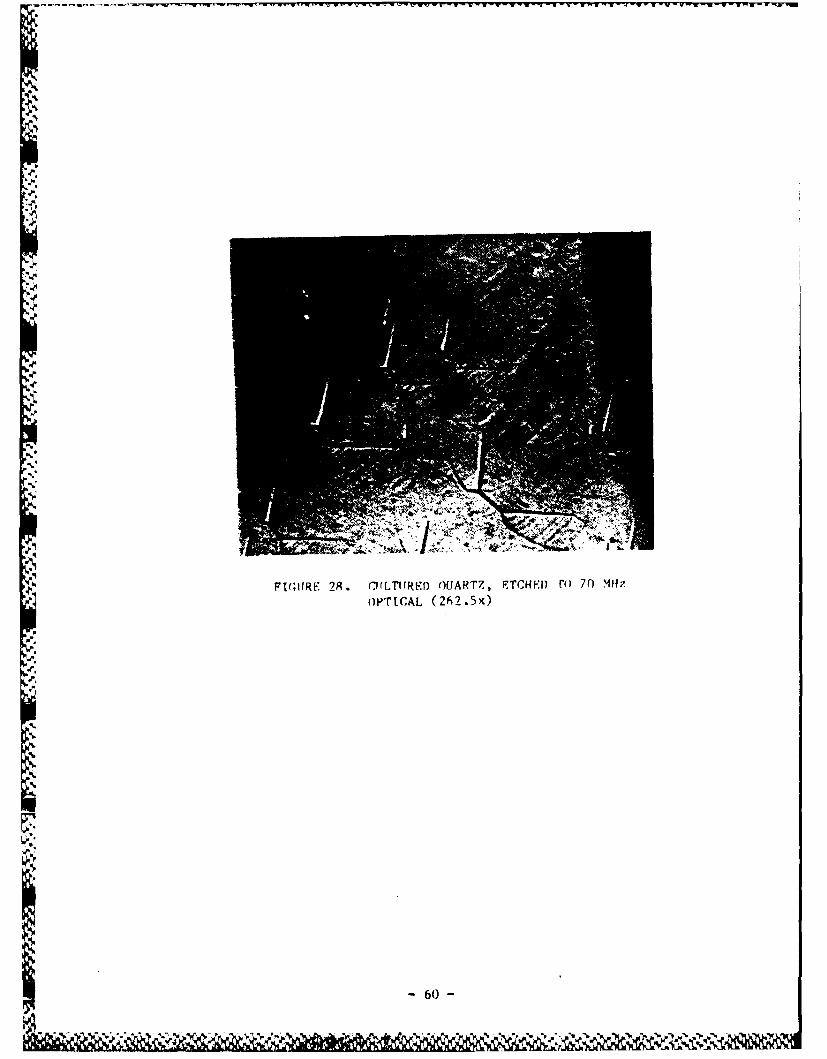
% visible as a dark line in the photograph. Figure 28 is another optical
microscope photograph (262.5x) showing the same phenomenon at higher
magnification. Again the photograph shows pairs of etch pits, one each on
both the top and bottom surface of the quartz membrane, each pair connected by
an etch channel which penetrates completely through the blank.
- 58 -
*%
•. -
Mr ali
FIUE2.CLURDQATECED3 IRMTR
FIGURE 2 CULTURED QUARTZ, ETCHED 3 0 MOETRS PTCA (105x)
p.59
N
4..
.4.'4.4.
.4'4.
4.4.4.
b
C,
-C.0%~~
C'-.
-S.
4.9~
4. Ft;I!Rt~ 2R . ~rrr TtrR~ 0 OUART7, FTCHI'1) r(J 70 MHzOPTICAL (2~ 5K)
p.
.4.
4..4..
4.
4.
5%,
is5%~
'sq
- 60 -
C'isW 4.4.' \~ ~(~P '~. 94.4. 4.' * ~1'
Both types of defects result in either device failure, as holes are
generated in the membrane, or severe degradation of the electrical
performance. It has been observed that not all etch pits have etch channels,
but that all observed etch channels begin and end at opposing etch pits.
Typically there are many more etch pits than etch channels observable after
etching.
Natural quartz has been used for the majority of the chemical etching
performed under this contract in order to reduce the incidence of etch
channels and pits. Cultured quartz can be post-processed by electrodiffusion
("sweeping".) Using suitably swept cultured quartz, etch channels can be
almost entirely eliminated [14]. With this technique, selected ions are made
to migrate under the influence of high temperature and electric fields toward
one face of a bar of quartz. This highly contaminated surface is then
removed, leaving a quartz bar relatively free of impurities.
:.61
*I, Because of the high cost and limited availability of commercially swept
quartz, it was decided to construct a small sweeping facility. During the
term of this contract three groups of cultured quartz bars were swept in an
electrodiffusion process. Only the first lot was processed into crystal
wafers and fabricated into final devices. During sweeping, the quartz was
brought from room temperature to 525°C over a twenty-four hour period. It was
maintained at 5250C with an electrical field of 1500 volts per centimeter of
thickness for a period of seven days. The temperature was then slowly lowered
to room temperature with the field still applied over a second twenty-four
hour period.
Both swept and unswept material from the same lot was fabricated into
polished blanks approximately 55 microns thick. The blanks were then etched
32 microns under the same conditions and inspected visually for etch channel
density. The unswept blanks exhibited a mean etch channel density of 481
channels per square centimeter with a sigma value of 298 channels. The mean
etch channel density for the swept blanks was 2.1 with a sigma value of 2.5.
While all the unswept blanks had etch channels, half of the swept blanks had
no etch channels at all.
The work performed to date with swept cultured quartz indicates that it
may no longer be necessary to use natural quartz in the production of VHF and
UHF fundamental crystal resonators. This would allow better control over the
quality of the starting material and favorably improve the consistency and
repeatability of future VHF crystal production.
- 62 -
- -'
2.5 Surface Finish Effects
Lapping crystals with an inert alumina lapping abrasive is a purely
mechanical process, but the polishing of quartz crystals is usually done with
media containing a chemically reactive rare earth oxide such as cerium
dioxide. This technique combines mechanical abrasion with chemical
dissolution and the resulting finish is often subject to hidden surface
damage. An amorphous silica layer often covers scratches which only become
visible after chemical etching.
An attempt was made to fabricate VHF resonators out of natural quartz
blanks which had been mechanically lapped with a 1 micron aluminum oxide
abrasive in lieu of polishing. The blanks were etched to 100 MHz fundamental
frequency and made into the resonators described in Section 2.3.2. The etched
surfaces are too microscopically rough to allow the observation of Haidinger's
fringes under monochromatic light, but are essentially scratch-free. The
highest Q observable on these units was 9 thousand and the lowest motional
resistance was 55.9 ohms. Units which were made from carefully polished
blanks had maximum Q's of 73 thousand and motional resistances as low as 14.5
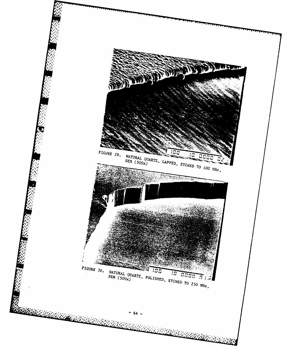
ohms. Figure 29 shows an SEM(500x) photograph of the etched surface finish of
a lapped crystal. An undulating surface can be seen, which remains even with
further etching. Figure 30 shows an SEM(500x) photograph of the etched
surface finish of a polished crystal. It is believed the observable surface
. differences are the main reason for the Q degradation on lapped blanks
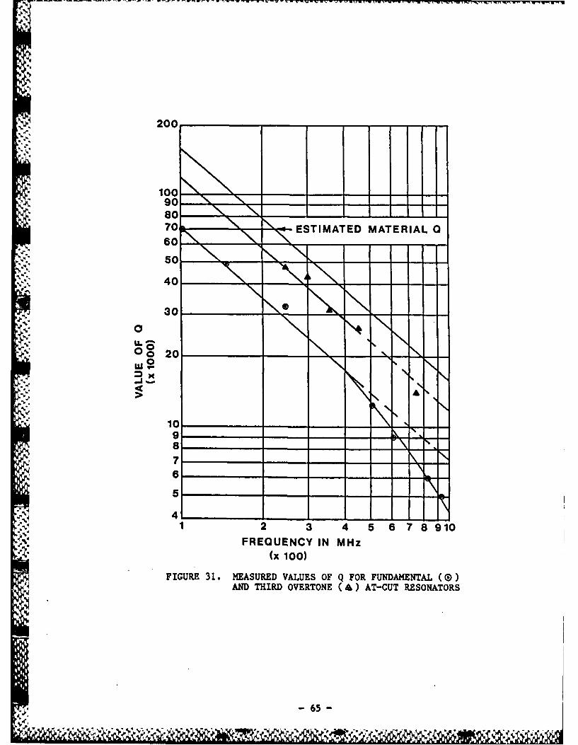
fabricated into VHF resonators. Figure 31 compares measured values of Q for
VHF and UHF resonators fabricated from polished blanks with the most probable
-63-
% % 1
FIGUpE 29. A
* ~ AUA QUART!JI.,-
SEM(50x) Z' APPETCHED TO10
-7A,
200
100
80 -
70- ESTIMATED MATERIAL60
"4. 50 '
40
30
A 00
LuJ ,,
-41
1 2 010
6 \
.r...,1 2 3 4 5 67 8910
FREQUENCY IN MHz(x 1oo)
FIGURE 31. MEASURED VALUES OF Q FOR FUNDAMENTAL (0)AND THIRD OVERTONE (&) AT-CUT RESONATORS
-65-
material Q [12] over a wide range of frequencies.
Third overtone measurements on the lapped-only blanks show multi-moded
responses, indicating lack of adequate parallelism. This is primarily due to
the lack of easy methods of determining blank parallelism of lapped surfaces,
rendering it impractical to monitor this aspect of the lapping process.
Polished blanks, on the other hand, can easily be checked for parallelism
by oberving self-interference fringes under a monochromatic light. Although
the lapped blanks are still suitable for many resonator applications, the
superior performance of polished blanks led to their being used predominantly
for this contract work.
2.6 Summary Of Results
Using wet chemical etching of polished, AT-cut quartz wafers, resonators
" have been fabricated at fundamental frequencies from 70 MHz to 1.6 GHz. In
figure 31 the best Q's achieved experimentally are compared with the estimated
material Q. Bearing in mind that electrode designs have not been optimized,
especially at the higher frequencies, these results are extremely encouraging.
"• Sweeping has successfully been used to produce cultured quartz which is
nearly free of etch channels. This material has been used to fabricate 100
"4. MHz resonators with good results.
Finally, to demonstrate the feasibility of using chemically milled
resonators in oscillators, a simple breadboard circuit, limited to 150 MHz by
transistor parameters, was built. Using suitable transistors and UHF
construction practice, the frequency range can be extended, but such activity
was beyond the scope of this program.
- 66 -
% % % %
-3 Conclusion
High fundamental frequency AT-cut resonators are potentially useful for
VHF, UHF, and microwave frequency generation as well as for VHF and UHF
crystal filters. The work performed to date has demonstrated the feasibility
of using wet chemical etching techniques to fabricate resonators at
fundamental frequencies into the gigahertz range. The processes used lend
themselves to practical manufacturing use. The work performed to date with
swept cultured quartz indicates that it can be used for the production of VHF
and UHF fundamental crystal resonators by etching. This will allow better
control over the quality of the starting material and improve the consistency
and repeatability of future VHF crystal production.
- -" Although the feasibility has been demonstrated and practical devices have
been made, there remain several areas for future work. These include improved
methods of final frequency adjustment, aging studies, the use of plasma
etching for wafer frequency adjustment, and phase noise and acceleration
sensitivity studies.
=67AV
.
* - 67 -
.. , .,. %, .,.% % . ,. ,,.,i,-..,/ . . .' '. ". -,, ,., "-%, r" ,-,, . ,,. . . - ,.. .,,. . . .. .. . . .
References:
[1] R.D. Colvin, "UHF Acoustic Oscillators," Microwave J., v. 23, no. 11,
pp. 22-23; November 1980.
[21 C. Pegeot, and G. Sauvage, UHF Oscillator Using SC-Cut Quartz Crystal
with Low Noise Performance & High Long Term Stability, "Proc. 34th
Annual Frequency Control Symposium, pp. 233-236; 1980.
(31 G.K. Guttwein, A.D. Ballato, and T.J. Lukaszed, "VHF-UHF Piezoelectric
Resonators," U.S. Pat. 3,694,677; 26 September, 1972.
[4] M. Berte, "Acoustic-Bulk-Wave Resonators & Filters Operating in the
Fundamental Mode at Frequency Greater than 100 MHz," El. Lett, v. 13,
no. 9, pp. 248-250, 28 April; 1977.
[5] M. Berte, "Acoustic-Bulk-Wave Resonators & Filters Operating in the
, Fundamental Mode at Frequencies Greater than 100 MHz," Proc. 31st Annual
Frequency Control Symposium, pp. 122-125; 1977.
[6] L. Bidart, and J. Chauvin, "Direct Frequency Crystal Oscillators,"Proc. 35th Annual Frequency Control Symposium, pp. 365-365; 1981.
[7] B. d'Albaret, and P. Siffert, "Recent Advances in UHF Crystal Filters,"
Proc. 36th Annual Frequency Control Symposium, pp. 405-418; 1982.
[81 J.P. Aubry, E. Gerard, and S. Lechopier (1983), "S.Y. Parameters Methodfor Accurate Measurements of Bulk Wave Crystal Resonator at Frequenciesup to 2 GHz," 37th Annual Frequency Control Symposium, pp. 306-316;1983.
[9] J.S. Wang, S.K. Watson, and K.F. Lau (1984), "Reactive ton Beam Etchingfor VHF Crystal Resonators," Proc. 38th Annual Frequency ControlSymposium, pp. 101-104; 1984.
[101 J.R. Vig, J.W. LeBus, and R.L. Filler, "Chemically Polished Quartz,"Proc. 31st Annual Frequency Control Symposium, pp. 131-143; 1977.
[11] R.C. Smythe, "An Automated Resonator Measurement System Using a
Reflection Coefficient Bridge," Proc. 35th Annual Frequency ControlSymposium, pp. 280-285; 1981.
[121 W.P. Mason, Physical Acoustics and the Properties of Solids, New York,
N.Y.: D. Van Nostrand Co. Inc., pp. 287-289; 1958.
[13] R.E. Bennett, Editor, "Quartz Resonator Handbook," Union Thermoelectric
Div., Comptometer Corp.; 1960.
L[141 J.G. Gualtieri and J.R. Vig, "Sweeping and Irradiation Studteq in
Quartz," Proc. 38th Annual Frequency Control Symposium, pp. 42-49; 1984.
68II.
5- -'--68 -
MISSION* Of
Ramw Air Development CenterRAVC ptanA and executes Aeeatch, development, testand 4eLected acquisition program6 in Aupport o6
* Command, Control, Communications and Intettigence(C31) activities. Technicat and enginee'ing"upport within aueaA o6 competence i. pouided toESV Program 06ices (P04) and other. ESO etementzto pe~oAm e6ective acquisition o6 C3 1 systems.The area6 o6 technicat competence inctudecommunications, command and controt, battLemanagement, in6ormation prLoce.64ing, Autve-itance4en~or4, intetUigence data cottection and handling,
* 6oLid state sciences, etectomagnetics, and. ', pr opagation, and etec tonic, maintainabiLity,
and copatibiLity.
, . .....
S°
9.,
I,
5%*
A-S ~
S.,.
-5,
I