Embed Size (px)
Citation preview
PERPUSTAKAAN UMP
I VU III ll IV 111 VII 11111 0000092511
EXPERIMENTAL STUDY ON FLOW AROUND
IMMERSED OBJECTS
LAILATUL JALILAII BIINTI KAHARUDIN
Thesis submitted in partial fulfillment of the requirements
for the award of the degree of
B. ENG (lIONS.) CIVIL ENGINEERING
Faculty of Civil Engineering & Earth Resources
UN1VERSITI MALAYSIA PAHANG
JUNE 2014
ABSTRACT
It is well known that when fluid flows around an object, the object will experience a force due to the interaction between the object and the fluid surrounding it. This study was conducted in an open channel using three different types of immersed objects (circular-shaped, rectangular-shaped, square-shaped) and was divided into two parts. The first part was on the investigation of wake length that results due to different immersed object shapes and fluid flow velocities. The experiments were carried out at different flow rates ranging from 2 L/s to 14 L/s and the corresponding wake lengths were measured. The results show that the wake length increases as the velocity increases. The second part of the study was on the investigation of the resultant drag force on the immersed objects during different combinations of object shapes and fluid flow velocities. Based on the experimental data, the Reynolds number for each immersed object was calculated and the drag coefficient of each immersed object was obtained from graphs and tables in established publications. It was found that the Reynolds numbers for both square and circular shape of the immersed objects were similar due to the frontal area of the objects that were taken into account in the calculations. The resultant drag force was calculated based on the drag coefficient obtained. From the results, the flowing water exerted the highest drag force on the immersed object that was rectangular-shaped compared to the other two shapes that was investigated. This is the effect of different drag coefficient values that are in turn based on the respective Reynolds number and object shape. Another finding was that when the velocity and drag coefficient were increased, the drag force values also increased.
Vi
ABSTRAK
Seperti yang diketahui bahawa apabila aliran mengalir di sekeliling objek, objek akan mengalami daya yang disebabkan oleh interaksi di antara objek clan cecair sekitamya. Kajian mi dijalankan. dalam saluran terbuka dengan menggunakan tiga jenis objek tenggelam (bentuk bulat, bentuk segi empat tepat, bentuk segi empat sama) dan dibahagikan kepada dua bahagian. Bahagian pertama adalah mengenai penyiasatan panjang 'wake' akibat kerana bentuk objek tenggelam berbeza dan halaju aliran bendalir. Kajian mi telah dijalankan pada kadar aliran yang berbeza dari 2 L / s 14 L I s dan panjang 'wake' sepadan telah diukur. Keputusan menunjukkan bahawa panjang 'wake' bertambah apabila halaju bertambah. Bahagian kedua kajian mi adalah berkenaan dengan penyiasatan daya seretan yang terhasil pada objek tenggelam dalam kombinasi yang berbeza bentuk objek dan halaju aliran bendalir. Berdasarkan data eksperimen, nombor Reynolds bagi setiap objek tenggelam dikira dan pekali seretan setiap objek tenggelarn telah diperolehi danipada graf dan jadual dalam penerbitan ditubuhkan. la telah mendapati bahawa nombor Reynolds bagi kedua-dua bentuk persegi dan bulat objek tenggelam adalah sama kerana kawasan hadapan objek yang telah diambil kira dalam pengiraan. Daya seretan terhasil dikira berdasarkan pekali seretan yang diperolehi. Daripada keputusan, air yang mengalir dikenakan daya seretan yang paling tinggi pada objek yang terendam yang segi empat tepat berbentuk berbanding dua bentuk yang lain yang telah dikaji. mi adalah kesan danipada nilai-nilai pekali seret yang berbeza yang seterusnya berdasarkan bilangan Reynolds masing-masing dan bentuk objek. Penemuan lain adalah bahawa apabila halaju dan pekali seretan telah meningkat, nilai daya seretan juga meningkat.
VII
TABLE OF CONTENTS
Page
SUPERVISOR'S DECLARATION
STUDENT'S DECLARATION
DEDICATION iv
ACKNOWLEDGEMENT v
ABSTRACT vi
ABSTRAK vii
TABLE OF CONTENTS viii
LIST OF TABLES xi
LIST OF FIGURES xii
LIST OF SYMBOLS xiv
LIST OF ABBREVIATIONS xv
CHAPTER 1 INTRODUCTION
1.1 Introduction 1
1.2 Problem Statement 4
1.3 Objective of the Research 4
1.4 Scope of Study 5
CHAPTER 2 LITERATURE REVIEW
2.1 Characteristics of Flow past an Object 6
2.2 Boundary Layer 9
2.3 Drag Force 10
2.3.1 Friction Drag 12 2.3.2 Pressure Drag 12
VIII
ix
2.4 Drag Coefficient 13
2.4.1 Object Shape 13 2.4.2 Reynolds Number 14
2.5 Wake Control
15
2.6 Past Experiment on Flow Immersed Object 1R
CHAPTER 3 METHODOLOGY
3.1 Introduction 19
3.2 Flowchart of the Study 20
3.3 Location of Experiment 21
3.4 Research Parameter Selection 21
3.5 Materials and Tools 23
3.6 Experimental Setup 26
3.7 Laboratory Experiment Procedure 27
CHAPTER 4 RESULTS AND DISCUSSIONS
4.1 Introduction 31
4.2 Data Collection 32
4.3 Wake behind Immersed Objects 33
4.4 Analysis of Wake 37
4.5 Drag Coefficient and Reynolds Number 39
4.5.1 Calculation of Reynolds Number 39 4.5.2 Analysis of Drag Coefficient and Reynolds Number 42 4.5.2.1 Circular Object Shape 43 4.5.2.2 Square Object Shape 44 4.5.2.3 Rectangle Object Shape 45 4.5.2.4 Drag Coefficient versus Reynolds Number 46
4.6 Drag Force 47
4.6.1 Calculation of Drag Force 47 4.6.2 Analysis of Drag Force 51
x
CHAPTER 5 CONCLUSION AND RECOMMENDATION
5.1 Conclusion 53
5.2 Recommendations 55
REFERENCES 56
APPENDICES
A Graph Drag Coefficient, Cd for Circular Shape 58
B Table Drag Coefficient, Cd for Square Shape 59
C Table Drag Coefficient, Cd for Rectangle Shape 60
D Table of Physical Properties of Water 61
E Laboratory Experiment 62
LIST OF TABLES
Table No. Title Page
3.1 Experiments parameter values 23
4.1 Experiments data recorded 33
4.2 Wake behind Circular Objects 35
4.3 Wake behind Square Objects 35
4.4 Wake behind Rectangle Objects 36
4.5 Reynolds number for Circular shape 40
4.6 Reynolds number for Square shape 41
4.7 Reynolds number for Rectangle shape 41
4.8 Re and CD for each objects 42
4.9 Data calculated for circular shape 48
4.10 Data calculated for square shape 49
4.11 Data calculated for rectangle shape 50
4.12 Drag force, FD for three objects 51
A
LIST OF FIGURES
Figure No. Title Page
1.1 Flow pattern past a cylinder 2
1.2 Water flowing around the object 3
2.1 Categories of bodies 7
2.2 Flows past flat plate 8
2.3 Boundary layer profile over a flat plate 9
2.4 Flows within the boundary layer along flat plate 10
2.5 Lift and drag concepts 11
2.6 Drag coefficient for an ellipse 14
2.7 Drag coefficient as a function of Reynolds number 15
2.8 Experiment using splitter plate 17
3.1 Flowchart of the Study 20
3.2 Hydraulic Laboratory, UMP 21
3.3 Size of open channel 22
3.4 Shapes of the objects 22
3.5 Object shapes 24
3.6 Flow meter 25
3.7 Meter Tape 25
3.8 Experimental setup 26
3.9 Water admits into the channel 27
3.10 Object place in the center 28
3.11 Measure using the flow meter 28
3.12 Height of water 29
3.13 Measure using meter tape 29
XII
XIII
3.14 Rectangle and square shapes 30
3.15 Control valve 30
4.1 Wake length vs. velocity for circular 37
4.2 Wake length vs. velocity for square 37
4.3 Wake length vs. velocity for rectangle 38
4.4 Wake length vs. velocity for different objects shapes 38
4.5 Drag coefficient vs. Reynolds number for circular 43
4.6 Drag coefficient vs. Reynolds number for square 44
4.7 Drag coefficient vs. Reynolds number for rectangle 45
4.8 Drag coefficient vs. Reynolds number 46
4.9 Drag force versus Velocity 52
LIST OF SYMBOLS
CD Drag coefficient
Re Reynolds number
Ma Mach number
Fr Froude number
L Lift
FD Drag force
V Velocity
P Density
D Diameter
A Area of the body
1 Length
V Kinematic viscosity
T Temperature
xiv
LIST OF ABBREVIATIONS
FKASA Faculty of Civil Engineering & Earth Resources
LDV Laser Doppler Velocimetry
LES Large Eddy Simulations
UMP Universiti Malaysia Pahang
Vs. Versus
xv
CHAPTER 1
INTRODUCTION
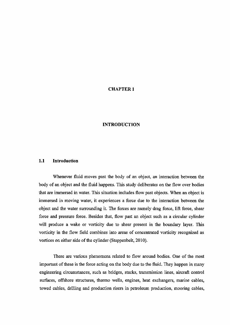
1.1 Introduction
Whenever fluid moves past the body of an object, an interaction between the
body of an object and the fluid happens. This study deliberates on the flow over bodies
that are immersed in water. This situation includes flow past objects. When an object is
immersed in moving water, it experiences a force due to the interaction between the
object and the water surrounding it. The forces are namely drag force, lift force, shear
force and pressure force. Besides that, flow past an object such as a circular cylinder
will produce a wake or vorticity due to shear present in the boundary layer. This
vorticity in the flow field combines into areas of concentrated vorticity recognized as
vortices on either side of the cylinder (Stappenbelt, 2010).
There are various phenomena related to flow around bodies. One of the most
important of these is the force acting on the body due to the fluid. They happen in many
engineering circumstances, such as bridges, stacks, transmission lines, aircraft control
surfaces, offshore structures, thermo wells, engines, heat exchangers, marine cables,
towed cables, drilling and production risers in petroleum production, mooring cables,
2
moored structures, tethered structures, buoyancy and spar hulls, pipelines, cable-laying,
members of jacketed structures, and other hydrodynamic as well as hydro acoustic
applications (Sarpkaya, 2004).
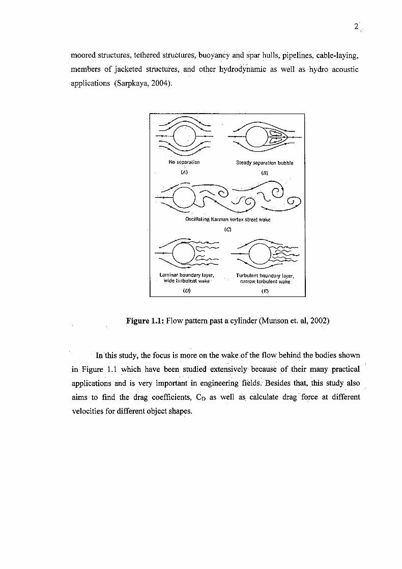
No separation Steady separation bubble
(A)
(II)
Oscillating Kariy,an vortex street wake
Larninar.boundary layer, wide turbulent wake
ID)
Turbulent boundary layer, narrow turbulent wake
(,)
Figure 1.1: Flow pattern past a cylinder (Munson et. al, 2002)
In this study, the focus is more on the wake of the flow behind the bodies shown
in Figure 1.1 which have been studied extensively because of their many practical
applications and is very important in engineering fields. Besides that, this study also
aims to find the drag coefficients, CD as well as calculate drag force at different
velocities for different object shapes.
CI
Figure 1.2: Water flowing around the object
The wake of the flow as shown in Figure 1.2 is determined üy numerous
parameters such as the size of . the shapes, orientation, fluid speed and fluid properties.
The shape of an object can affect the length of the wake behind it. Besides that, the drag
coefficient for objects is influenced by the shape of the objects. In this study, several
physical bodies were used to obtain the results based on different form of shapes. One
part of the experiment deliberates on the length of the wake that appears when water is
flowing past the immersed objects. The part of the experiment endeavors, to estimate
the drag force exerted on the immersed objects. The experiments are conducted under
different flow rates for each different form of the object. Finally, the conclusions of the
accomplishments in this experiment are prepared.
4
1.2 Problem Statement
Several practical circumstances contain flow past bodies. When a fluid moves
through bodies, an interaction between the bodies and the fluid arises. According to Suh
et al. (2011), flow past bodies is an important topic because of its varied applications in
engineering and its abundant flow physics including separations, reattachment, vortex
shedding, etc. For example, take the piers of a bridge. Piers act as the main support for a
bridge, on which the bridge superstructure rests. The shape Of the piers can affect the
flow of the water. The piers will obstruct the flow, causing vibrations at the piers which
may lead to structural failure. The shape of an object also affects the flow wake.
Furthermore, whatever may be the shape of pier provided, the obstruction to flow within
the channel is unavoidable (Suribabu et al., 2011). Besides that, the drag coefficient for
an object is influence by the shape of the objects.
1.3 Objectives of the Research
The objectives of this study are:
i. To investigate the relationship between wake length and flow velocity
for different immersed object shapes
ii. To estimate the drag force exerted on immersed objects of different
shapes at different velocities
5
1.4 Scope of Study
For this study, the consideration is more to flow past or around immersed
bodies. This study used the hydraulic laboratory to perform the experiment. In the
laboratory, the open channel flow experiment facility was used. There are three form
objects that were used to figure the results for different type of shapes. The shapes
include circular, rectangular and square objects such as plastic pipe. In the experiment,
the works done are:
i. To measure the length of the wake that arises when water is flowing past the
immersed objects.
ii. To measure velocity and the height of the water that occurs when water is
flowing past the immersed objects.
iii. To estimate the drag force at different flow velocities.
CHAPTER 2
LITERATURE REVIEW
2.1 Characteristics of Flow past an Object
Flow past immersed objects or external flows past objects, are flows of fluids
surrounding objects with solid walls, subject to no outer boundary, except in the
particularly infinite distance from the object. Examples are flows around ground
structure or land, and water flows around marine and water vehicles. In contrast,
internal flows are those in which the following fluid is surrounded by solid walls, such
as flows through pipes, ducts and canals or within fluid machinery.
When fluid moves through or around objects, an interaction between the objects
and the fluid happens. An object immersed in a flowing fluid will commonly experience
a force, whose magnitude and direction depend on several parameters. This effect can
be defined in terms of the forces on the fluid and body boundary. An entirely immersed
solid object, causing a constant relative speed with regard to an unbounded,
incompressible and frictionless fluid, will receive zero strength.
7
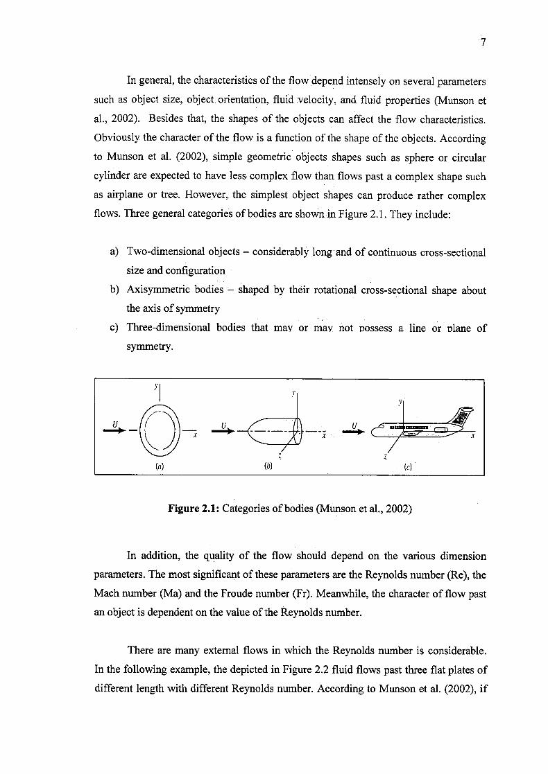
In general, the characteristics of the flow depend intensely on several parameters
such as object size, object. orientation, fluid velocity, and fluid properties (Munson et
al., 2002). Besides that, the shapes of the objects can affect the flow characteristics.
Obviously the character of the flow is a function of the shape of the objects. According
to Munson et al. (2002), simple geometric objects shapes such as sphere or circular
cylinder are expected to have less complex flow than flows past a complex shape such
as airplane or tree. However,, the simplest object shapes can produce rather complex
flows. Three general categories of bodies are shown.-in Figure 2.1. They include:
a) Two-dimensional objects - considerably long and of continuous cross-sectional
size and configuration
b) Axisymmetric bodies - shaped by their rotational cross-sectional shape about
the axis of symmetry
c) Three-dimensional bodies that may or may not nossess a line or nlane of
symmetry.
0 X
(a)
(b)
(c)
Figure 2.1: Categories of bodies (Munson etal., 2002)
In addition, the quality of the flow should depend on the various dimension
parameters. The most significant of these parameters are the Reynolds number (Re), the
Mach number (Ma) and the Froude number (Fr). Meanwhile, the character of flow past
an object is dependent on the value of the Reynolds number.
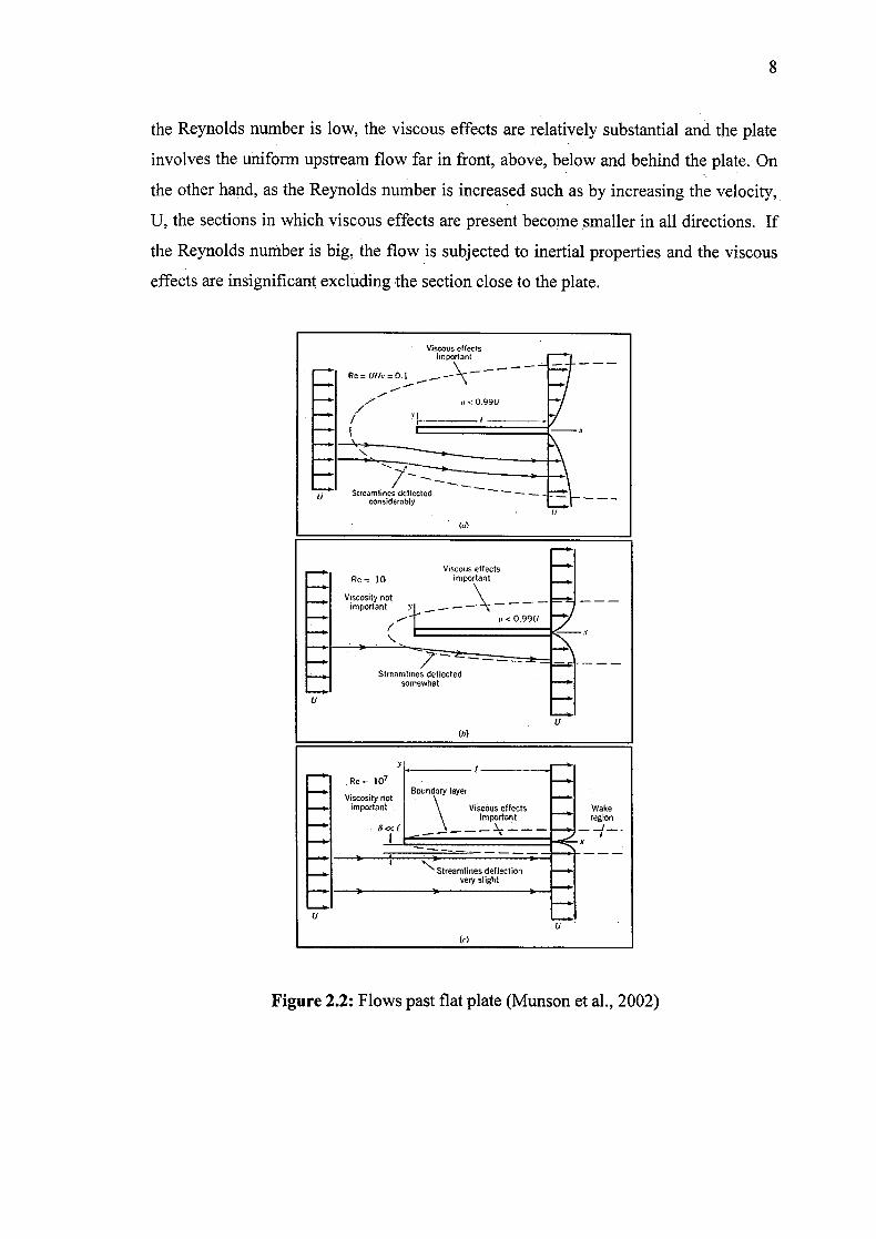
There are many external flows in which the Reynolds number is considerable.
In the following example, the depicted in Figure 2.2 fluid flows past three flat plates of
different length with different Reynolds number. According to Munson et al. (2002), if
8
the Reynolds number is low, the viscous effects are relatively substantial and the plate
involves the uniform upstream flow far in front, above, below and behind the plate. On
the other hand, as the Reynolds number is increased such as by increasing the velocity,
U, the sections in which viscous effects are present become smaller in all directions. If
the Reynolds number is big, the flow is subjected to inertial properties and the viscous
effects are insignificant excluding the section close to the plate.
Viscous effects important
-
0< 099U
-HStreamlines deflected - - -
considerably
Viscous effects Re= 10 impsr ant
Viscosity not important 1 — - - -
— 1 it < 0991.1
3.
Streamlines deflected somewhat
U
• ___I
.Re= 107 -j Viscosity not
Boundary layer
important \ Viscous effects Waite \ importaht region
1-
Streamlines deflection very slight
U
LI
U
Figure 2.2: Flows past flat plate (Munson et al., 2002)
2.2 Boundary Layer
Commonly, the viscosity of a fluid only plays a role in a thin layer, for example
laterally in a solid boundary as Prandtl showed for the first time in 1904 (Veidman,
2012). The thin layer is called a boundary layer depicted in Figure 2.3 by Prandtl.
Besides that, ,Prandtl overcome of a thin section close to the solid surface where the
effects of viscosity are felt and the velocity passes from zero at the wall to the value
corresponding to not rotating flow (Buresti, 2000).
:"-
*1 ____
wa
Figure 2.3: Boundary layer profile over a flat plate (Buresti, 2000)
In theory, the equations capable of describing the flow (liquid or gas) past any
object can be obtained by solving the Navier-Stokes equations. Meanwhile, the Navier-
Stokes equations can be simplified for boundary layer flow analysis.
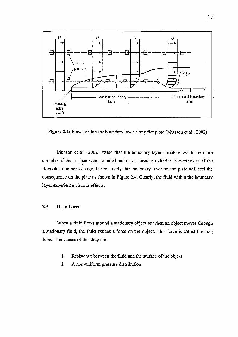
The dimensions of boundary layer and the structure of the stream can show a
wide diversity within it. This variation occurs due to the configuration of the object on
which the boundary layer forms. For example, the boundary layer which is organized
along a long flat plate along which flows a viscous, incompressible fluid.
1•0
U . U U U
B -' - - -B------ - "El--
Fluid lparticle I/,
Laminar boundary 4,. Turbulent boundary
Leading layer layer
edge = 0
Figure 2.4: Flows within the boundary layer along flat plate (Munson et al., 2002)
Munson et al. (2002) stated that the boundary layer structure would be more
complex if the surface were rounded such as a circular cylinder. Nevertheless, if the
Reynolds number is large, the relatively thin boundary layer on the plate will feel the
consequence on the plate as shown in Figure 2.4. Clearly, the fluid within the boundary
layer experience viscous effects.
2.3 Drag Force
When a fluid flows around a stationary object or when an object moves through
a stationary fluid, the fluid exudes a force on the object. This force is called the drag
force. The causes of this drag are:
i. Resistance between the fluid and the surface of the object
ii. A non-uniform pressure distribution
I
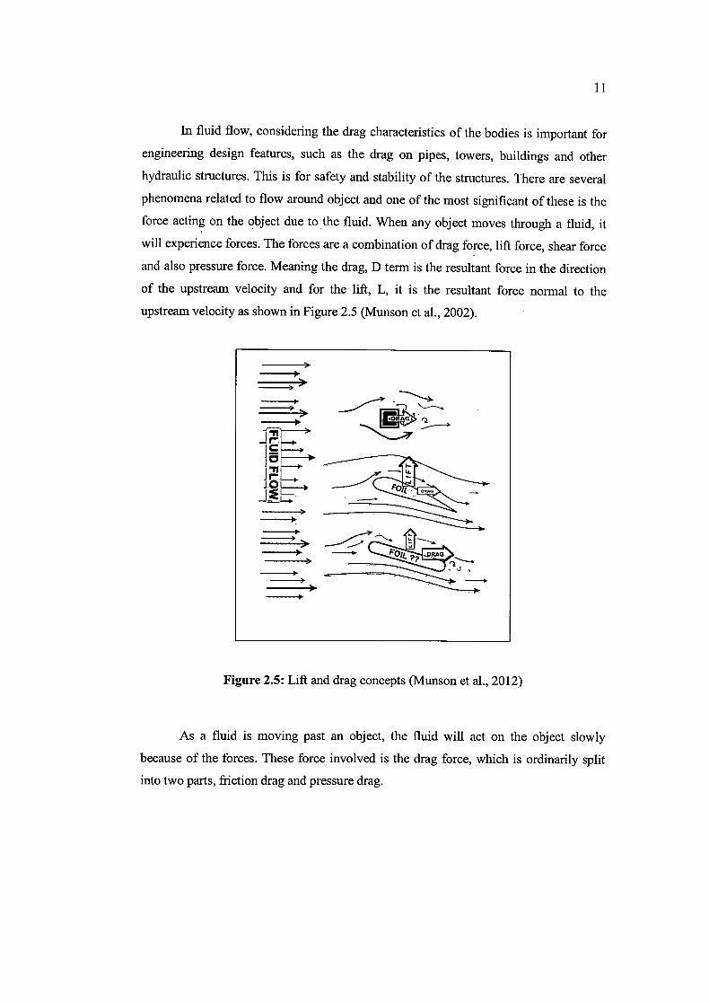
In fluid flow, considering the drag characteristics of the bodies is important for
engineering design features, such as the drag on pipes, towers, buildings and other
hydraulic structures. This is for safety and stability of the structures. There are several
phenomena related to flow around object and one of the most significant of these is the
force acting on the object due to the fluid. When any object moves through a fluid, it
will experience forces. The forces are a combination of drag force, lift force, shear force
and also pressure force. Meaning the drag, D term is the resultant force in the direction
of the upstream velocity and for the lift, L, it is the resultant force normal to the
upstream velocity as shown in Figure 2.5 (Munson et al., 2002).
)>
1)>
'- P07
Figure 2.5: Lift and drag concepts (Munson et al., 2012)
As a fluid is moving past an object, the fluid will act on the object slowly
because of the forces. These force involved is the drag force, which is ordinarily split
into two parts, friction drag and pressure drag.
12
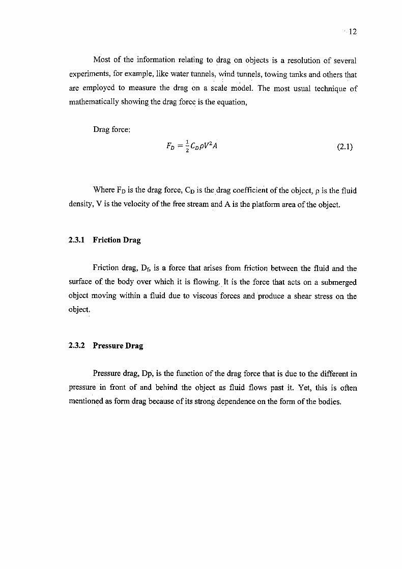
Most of the information relating to drag on objects 'is a resolution of several
experiments, for example, like water tunnels, wind tunnels, towing tanks and others that
are employed to measure the drag on a scale model. The most usual technique of
mathematically showing the drag force is the equation,
Drag force:
FD = -CD PVA
(2.1)
Where FD is the drag force, CD is the drag coefficient of the object, p is the fluid
density, V is the velocity of the free stream and A is the platform area of the object.
2.3.1 Friction Drag
Friction drag, Df, is a force that arises from friction between the fluid and the
surface of the body over which it is flowing. It is the force that acts on a submerged
object moving within a fluid due to viscous forces and produce a shear stress on the
object.
2.3.2 Pressure Drag
Pressure drag, Dp, is the function of the drag force that is due to the different in
pressure in front of and behind the object as fluid flows past it. Yet, this is often
mentioned as form drag because of its strong dependence on the form of the bodies.
13
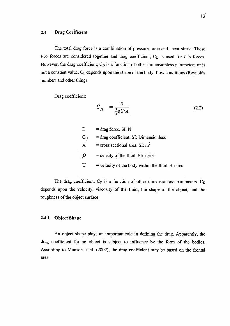
2.4 Drag Coefficient
The total drag force is a combination of pressure force and shear stress. These
two forces are considered together and drag coefficient, CD is used for this forces.
However, the drag coefficient, CD is a function of other dimensionless parameters or is
not a constant value. CD depends upon the shape of the body, flow conditions (Reynolds
number) and other things.
Drag coefficient:
D
D pU2A (2.2)
D = drag force. SI: N
CD drag coefficient. SI: Dimensionless
A = cross sectional area. SI: m2
= density of the fluid. SL kg/rn3
U = velocity of the body within the fluid. SI: m/s
The drag coefficient, CD is a function of other dimensionless parameters. CD
depends upon the velocity, viscosity of the fluid, the shape of the object, and the
roughness of the object surface.
2.4.1 Object Shape
An object shape plays an important role in defining the drag. Apparently, the
drag coefficient for an object is subject to influence by the form of the bodies.
According to Munson et al. (2002), the drag coefficient may be based on the frontal
area.