Embed Size (px)
Citation preview

Parts List
PL 008-714September 2018
I/A Series® Intelligent Vortex Flowmeters—
Models 84W-T, 84W-U, and 84W-LWafer Body Flowmeters
—with
HART Communication Protocol
Give instrument Model Code when ordering.*Parts preceded by an asterisk are recommended spare parts.
See Recommended Spare Parts Summary section for quantities.
TO ORDER PARTS, CALL 1-866-746-6477.

PL 008-714Page 2 MODEL CODE
MODEL CODE
Description ModelIntelligent Vortex Flowmeter – Wafer Body 84W
Electronics TypeIntelligent Electronics, HART Communication Protocol, with Pulse Output -TIntelligent Electronics, HART Communication Protocol, without Pulse Output -UIntelligent, Electronics, Low Power HART Protocol, with Pulse Output -L
Nominal Line Size3/4 in (DN 15) Line Size 3Q1 in (DN 25) Line Size 011 1/2 in (DN 40) Line Size 1H2 in (DN 50) Line Size 023 in (DN 80) Line Size 034 in (DN 100) Line Size 046 in (DN 150) Line Size 068 in (DN 200) Line Size 08
Body and Shedder Bar MaterialASTM A351-CF8M (316 ss) Cast Body and Shedder SASTM A494-CW2M Nickel Alloy (a) Cast Body and Shedder; with Size Codes 3Q to 04 only H
Mounting and Centering System
Description Used with Line SizesCentering for ANSI Class 150 and 300 Flanges All line sizes 1Centering for ANSI Class 600 Flanges 3Q through 04 only Centering for Metric PN 16 Flange 01 through 03 onlyCentering for Metric PN 40 Flange 01 through 03 and 06 and 08 onlyCentering for Metric PN 63 and PN 100 Flanges All line sizesCentering for ANSI Class 600 Flange 06 and 08 only 3Centering for Metric PN 16 Flange 04, 06, and 08 only 4Centering for Metric PN 40 Flange 04 only 5Centering for Metric PN 16 and PN 40 Flanges Size 3Q only 9
Isolation Valve and ManifoldNo Isolation Valve or Manifold SManifold with Isolation Valve, ASTM A 351-CF8M Stainless Steel (316 ss) K
Sensor Fill, Temperature Range, and Material
Standard Temperature Range (with Fill Fluid)Fluorolube Fill, 0 to 200°F (-18 to +93°C), Nickel Alloy CW2M (a) DFluorolube Fill, 0 to 200°F (-18 to +93°C), Stainless Steel Type CF3M FSilicone Fill, 0 to 400°F (-18 to +204°C), Nickel Alloy CW2M (a) RSilicone Fill, 0 to 400°F (-18 to +204°C), Stainless Steel Type CF3M S
Extended Temperature Range (No Fill Fluid) (b)Unfilled, 300 to 800°F (149 to 427°C), Nickel Alloy CW2M (a) CUnfilled, 300 to 800°F (149 to 427°C), Stainless Steel Type CF3M T
Electronics Housing Mounting, Material, and Conduit ConnectionsIntegrally Mounted to Flowtube; Aluminum Housing, 1/2 NPT Conduit Connection TIntegrally Mounted to Flowtube; Aluminum Housing, M20 Conduit Connection VRemote Mounted; Aluminum Housing, 1/2 NPT Conduit Connection (c) RRemote Mounted; Aluminum Housing, M20 Conduit Connection (c) W
Local Digital Indicator/ConfiguratorNo Digital Indicator/Configurator NFull Function Digital Indicator/Configurator J

MODEL CODE
PL 008-714Page 3
Electrical Safety (refer to Electrical Safety Specifications section for details)ATEX intrinsically Safe EATEX flameproof HCSA intrinsically safe CCSA Division 2 MCSA explosionproof DEAC intrinsically safe 1EAC flameproof 2FM intrinsically safe FFM nonincendive KFM explosionproof GIECEx intrinsically safe LIECEx flameproof BINMETRO intrinsically safe 3INMETRO flameproof 4KOSHA, flameproof 5NEPSI intrinsically safe RNEPSI flameproof SNo Agency Electrical Certifications; with CE mark, PED Controls and Records YNo Agency Certifications; no CE mark; Units not to be installed in European Union (EU) countries Z
Optional Selections
Cable Length Selection for Remote Electronics Housing20 ft (6 m) Cable to Connect to Remote Electronics Housing -B30 ft (9 m) Cable to Connect to Remote Electronics Housing -D40 ft (12 m) Cable to Connect to Remote Electronics Housing -E50 ft (15 m) Cable to Connect to Remote Electronics Housing -G
Cleaning - Oxygen/Chlorine ServiceCleaning of Process Wetted Parts per Compressed Gas Association's CGA G-4.1 and ASTM G93 -H Not available with Isolation Valve Code K, or Sensor Codes C and T
Sensor Plating -JGold Plated Sensor
Schneider Electric Certificates of Compliance/ConformanceStandard Certificate of Compliance -LMaterial Certification of Process Wetted Metal (Conforms to BS EN 10204 3.1) -MProcess Wetted Parts Comply with NACE Standards MR-0175-2003 and MR-0103-2007 -Q
Schneider Electric Calibration CertificateCalibration and Pressure Test Certified Copy -N
Cable Connectors – with Electronics Housing Codes T and R only (1/2 NPT)Hawke-Type Cable Gland (available only with electrical safety codes Y and Z) -PPG11 Cable Gland, Trumpet Shaped (not with explosionproof/flameproof certifications) -R
Conduit FittingAdapter for use with 1/2 NPT conduit (Available with Remote Mounted Housing Code R only) -T
Instruction ManualDetailed Instruction Manual in hard copy format (d) -C
Examples: 84W-T02S1SRRJF-D; 84W-U04H4SRTNF-CL
a. Equivalent to Hastelloy® C-4C. Hastelloy® is a registered trademark of Haynes International, Inc.b. Application ALERT: For Extended Temperature Range sensors used in hazardous or volatile gas applications, there is the
potential of fugitive emissions to occur through the sensor vented restrictor if the sensor diaphragm were to fail.
c. With remote mounted electronics housing, you must also select Optional Cable Length -B, -D, E, or -G.
d. A DVD containing the full documentation set is shipped standard with this product.
Description Model

PL 008-714Page 4 PARTS
PARTS
Figure 1. MODEL 84W ELECTRONICS HOUSING ASSEMBLY
DATA PLATE ENCIRCLES NECK OF ELECTRONICS HOUSING
POWER WIRES TOTERMINAL BLOCK
CONNECTOR FOR CABLE FROM INDICATOR/CONFIGURATOR
7
76
4 1
15
14
5
9
32
4
13
SOLID COVER
SOLID COVER WHENINDICATOR/CONFIGURATOR(ITEM 9) IS NOT SELECTED. STANDARD LENGTH
11
10
TERMINAL BLOCK
23
17
3
3
FIELD WIRING END
ELECTRONICS END
8
13
12
16
18
1921 20
225
WINDOW COVER WHEN INDICATOR/CONFIGURATOR (ITEM 9) IS SELECTED.EXTENDED LENGTH
24
PARTS
PL 008-714Page 5
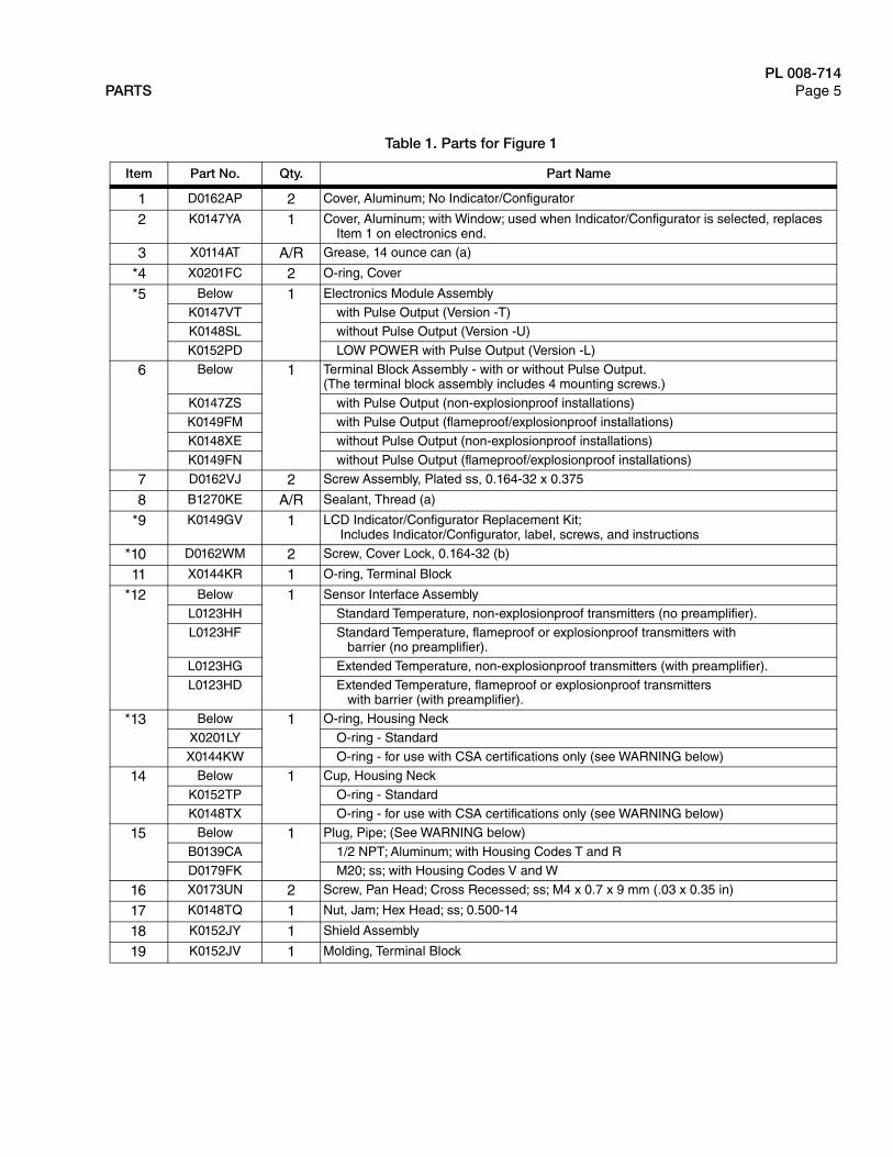
Table 1. Parts for Figure 1
Item Part No. Qty. Part Name
1 D0162AP 2 Cover, Aluminum; No Indicator/Configurator
2 K0147YA 1 Cover, Aluminum; with Window; used when Indicator/Configurator is selected, replaces Item 1 on electronics end.
3 X0114AT A/R Grease, 14 ounce can (a)
*4 X0201FC 2 O-ring, Cover
*5 Below 1 Electronics Module Assembly
K0147VT with Pulse Output (Version -T)K0148SL without Pulse Output (Version -U)
K0152PD LOW POWER with Pulse Output (Version -L)
6 Below 1 Terminal Block Assembly - with or without Pulse Output.(The terminal block assembly includes 4 mounting screws.)
K0147ZS with Pulse Output (non-explosionproof installations)
K0149FM with Pulse Output (flameproof/explosionproof installations)K0148XE without Pulse Output (non-explosionproof installations)
K0149FN without Pulse Output (flameproof/explosionproof installations)
7 D0162VJ 2 Screw Assembly, Plated ss, 0.164-32 x 0.375
8 B1270KE A/R Sealant, Thread (a)
*9 K0149GV 1 LCD Indicator/Configurator Replacement Kit; Includes Indicator/Configurator, label, screws, and instructions
*10 D0162WM 2 Screw, Cover Lock, 0.164-32 (b)
11 X0144KR 1 O-ring, Terminal Block
*12 Below 1 Sensor Interface Assembly
L0123HH Standard Temperature, non-explosionproof transmitters (no preamplifier).
L0123HF Standard Temperature, flameproof or explosionproof transmitters withbarrier (no preamplifier).
L0123HG Extended Temperature, non-explosionproof transmitters (with preamplifier).
L0123HD Extended Temperature, flameproof or explosionproof transmitterswith barrier (with preamplifier).
*13 Below 1 O-ring, Housing Neck
X0201LY O-ring - StandardX0144KW O-ring - for use with CSA certifications only (see WARNING below)
14 Below 1 Cup, Housing Neck
K0152TP O-ring - StandardK0148TX O-ring - for use with CSA certifications only (see WARNING below)
15 Below 1 Plug, Pipe; (See WARNING below)
B0139CA 1/2 NPT; Aluminum; with Housing Codes T and RD0179FK M20; ss; with Housing Codes V and W
16 X0173UN 2 Screw, Pan Head; Cross Recessed; ss; M4 x 0.7 x 9 mm (.03 x 0.35 in)
17 K0148TQ 1 Nut, Jam; Hex Head; ss; 0.500-14
18 K0152JY 1 Shield Assembly
19 K0152JV 1 Molding, Terminal Block

PL 008-714Page 6 PARTS
20 K0152JX 1 Screw Assembly, P.E.; ss; 0.164-32 x 0.315
21 X0133VN 1 Screw, Socket Head; ss; 0.138-32 x 0.437
22 K0152KU 1 Harness, Test; Accessory (c)
23 D0197PS 1 Clip, Retention
24 X0174EK 1 Screw, Button Head
a. Recommended lubricant and thread sealant is indicated for threaded parts. An equivalent commercially available equivalent lubricant or thread sealant may also be used.
b. Cover lock screws are provided with ATEX/IECEx/NEPSI/INMETRO/EAC/KOSHA flameproof electrical certifications. They are used to help prevent rotation of the housing covers. To remove a cover, turn screw clockwise until screw clears the cover groove; then remove cover. To put cover back in place, screw cover on, and then turn screw counterclockwise until it engages the cover groove.
c. The test harness provides a method for inputting a frequency using a frequency generator, for those users who require a test input for validation.
WARNINGRISK OF MOISTURE INGRESS
To maintain IP66 (IEC 529) and NEMA 4X protection, the unused conduit opening must be closed with a metal plug. In addition, the threaded housing covers must be properly installed.
Failure to follow these instructions can result in death or serious injury.
WARNINGRISK OF ANSI/ISA NONCOMPLIANCE
Failure to install the proper Housing Neck O-ring and Housing Neck Cup (Items 13 and 14) for CSA-labeled products violates ANSI/ISA 12.27.01.
Failure to follow these instructions can result in death or serious injury.
Table 1. Parts for Figure 1 (Continued)
Item Part No. Qty. Part Name
!
!

PARTS
PL 008-714Page 7
Figure 2. MODEL 84W FLOWMETER ASSEMBLY WITH REMOTE MOUNTED ELECTRONICS HOUSING
7
O-RING IS PART OF ITEM 1, BUTMAY BE ORDERED SEPARATELY.
EXTENDED (HIGH) TEMPERATURERANGE ASSEMBLY SHOWN
BONNET ASSEMBLYATTACHES TO FLOWTUBEBODY OR TO ISOLATIONVALVE, AS APPLICABLE.
6
4
2
1
COVER PART OF ITEM 1
5
3
12
8 9 10
12
11
ITEM 11 OPTIONAL CONDUIT CONNECTION (OPTION -T) ISREQUIRED ON BOTH ENDSOF CABLE ASSEMBLY WHENCONDUIT IS USED IN THEINSTALLATION.
ELECTRONICS HOUSINGASSEMBLY PARTS ARESHOWN IN FIGURE 1.
13
14
1112
POTTED ENDOF CABLEASSEMBLY
16
17
15
OPTIONAL CONDUITCONNECTION (OPTION-T)
20
19
18
212
22
26
25

PL 008-714Page 8 PARTS
Table 2. Parts for Figure 2
Item Part No. Qty. Part Name
1 K0152GB 1 Connection Head Assembly (Junction Box); explosionproof; ss;Includes housing, cover, cover lock, and cover O-ring
2 X0114AT A/R Grease, 14 ounce can (a)
*3 Below 1 Preamplifier Assembly
L0123HT Standard Temperature
L0123HV Extended Temperature
4 X0173UN 2 Screw, Pan Head; Cross-recessed; ss; M4 x 0.7 x 9 mm (.03 x 0.35 in)
5 X0201KL 2 Standoff, hexagonal head; ss; M4 x 10 mm (.39 in)
*6 D0179EG 1 O-ring, Cover; Part of Item 1 but may be ordered separately
7 Below 1 Cable Assembly, Remote Housing (includes Connector Assembly) (b)
K0149HU 20 ft (6 m) long
K0149HV 30 ft (9 m) longK0149HW 40 ft (12 m) long
K0149HX 50 ft (15 m) long
8 B0185AJ 1 Adapter; 1.125 Hexhd; ss; 1/2 NPT and 0.500-20
9 K0146JV 1 Bushing, silicone rubber; 0.275 in long; 0.280 I.D.
10 B0185AK 1 Nut, Knurled; ss; 0.542 in long; 0.500-20
11 K0149LE 2 Connector, Conduit; Option -T (required when conduit is used)
12 B1270KE A/R Sealant, Thread (a)
*13 Below 1 O-ring, Housing Neck
X0201LY O-ring - Standard
X0144KW O-ring - for use with CSA certifications only - See WARNING below
14 K0148TQ 2 Nut Jam; 1.250 Hexhd; ss; 0.500-20
15 K0149HR 1 Bracket Assembly, Mounting; painted steel
16 D0114SM 1 U-Bolt, 0.312-18; plated steel
17 0011962 2 Nut, 0.312-18; plated steel
*18 Below 1 Sensor Interface Assembly
L0123HH Standard and Extended Temperature, intrinsically safe transmitters(no preamplifier).
L0123HF Standard and Extended Temperature, flameproof or explosionproof transmitters with barrier (no preamplifier).
19 K0152JY 1 Physical Ground (PE) Shield Assembly (flameproof units only)
20 X0173UN 2 Screw, Panhd; Cross Recessed; ss; M4 x 0.7 x 9 mm (.03 x 0.35 in) with barrier (no preamplifier)

PARTS
PL 008-714Page 9
21 Below 1 Cup, Housing Neck
K0152TP Cup - Standard
K0148TX Cup - for use with CSA certifications only - see WARNING below
22 X0143SL 1 Washer, Lock; Extended Tooth; ss; 0.875
25 D0197PS 1 Clip, Retaining
26 X0174EK 1 Screw, Button Head
a. Recommended lubricant and thread sealant is indicated for threaded parts. An equivalent commercially available equivalent lubricant or thread sealant may also be used.
b. The cable assembly is provided potted on the electronics housing end. The opposite end is assembled to the connection head assembly using a bushing (Item 9) and a knurled nut (Item 10) as described in instruction document MI 019-202. When a conduit is used during installation, a conduit connector is used at each end of the cable assembly.
WARNINGRISK OF ANSI/ISA NONCOMPLIANCE
Failure to install the proper Housing Neck O-ring and Housing Neck Cup (Items 13 and 14) for CSA-labeled products violates ANSI/ISA 12.27.01.
Failure to follow these instructions can result in death or serious injury.
Table 2. Parts for Figure 2 (Continued)
Item Part No. Qty. Part Name
!

PL 008-714Page 10 PARTS
Figure 3. 84W - SINGLE MEASUREMENT FLOWMETERS STANDARD OR EXTENDED (EXT.) TEMPERATURE,
WITH OR WITHOUT ISOLATION MANIFOLD(MODEL 84F (STYLE A) IS SHOWN. ASSEMBLY IS SIMILAR TO 84W)
STD. TEMP.BONNET
STD. TEMP.SENSOR
STD. TEMP.BONNET
STD. TEMP.SENSOR
1
2
3EXT. TEMP. BONNET
126
10
11
8
9
11
10
11
10
9
EXT. TEMP.SENSOR
ISOLATIONVALVE
ELECTRONICS HOUSING ASSEMBLYSEE FIGURE 1
ILLUSTRATED WITHOUT ISOLATION VALVESHOWN WITH ITEM 5, SHROUD,
FOR ATEX FLAMEPROOF APPLICATIONS.ALSO SHOWN WITH
MODEL 84F (Style A) FLANGED BODY FLOWTUBEAND ALSO AVAILABLE WITH
MODEL 84W WAFER BODY FLOWTUBE.ILLUSTRATED WITH ISOLATION VALVE
SHOWN WITHMODEL 84F (Style A) FLANGED BODY FLOWTUBE.
ALSO AVAILABLE WITHMODEL 84W WAFER BODY FLOWTUBE
EXT. TEMP.SENSOR7
8
7
CONNECTIONHEAD ASSEMBLY(JUNCTION BOX).SEE FIGURE 2.
CONNECTION HEAD ASSEMBLY(JUNCTION BOX).SEE FIGURE 2.
4
13
4
13
4
6
13
1414

PARTS
PL 008-714Page 11
Table 3. Parts for Figure 3
Item Part No. Qty. Part Name
*1 Below 1 O-ring, Housing Neck
X0201LY O-ring - Standard
X0144KW O-ring - for use with CSA certifications only (see WARNING below)
2 Below 1 Cup, Housing NeckK0152TP Cup - Standard
K0148TX Cup - for use with CSA certifications only (see WARNING below)
3 K0148TQ 1 Nut, Jam; Hexhd; ss; 0.500-14
4 Table 1 1 Bonnet Assembly, Standard or Extended Temperature Ranges (a)
a. The bonnet assembly and sensor kits are pressure containment components. Replacement of any of these components requires pressure safety testing. Refer to Instruction manual.
6 X0173MC 4/8 Bolt, ASTM A193, Grade B7, plated steel (b) (Also part of Item 7)Hexhd (0.625 hex); 0.437-14 x 1.5
b. Four bolts required when no isolation valve is used; eight bolts required when an isolation valve is used. Threads may be lubricated with an equivalent commercially available lubricant.
*7 Below Below Sensor Replacement Kit (Items 6, 8, 9, 10, and 11) (a) (c) (d)
c. Do not use Sensor Replacement Kits and Sensor Seal Kits (Table 5 and Table 6) for sensors that are used for oxygen service. These require special cleaning. Contact Global Customer Support.
d. For gold plated sensor replacement, contact Global Customer Support.
8 Table 2 1 O-ring, Standard or Extended Temperature Range
9 Table 2 1 Sensor, Types D, F, R, S, C, or T (Model Code Selections)
10 Table 2 1 Gasket, Standard or Extended Temperature Range
11 Table 2 1 Flow Dam, Standard or Extended Temperature Range
12 Below 1 Isolation Valve
B0194VZ Standard Temperature Range; 15 to 80 mm (3/4 to 3 in) Sizes
B0194WA Standard Temperature Range; 100 to 300 mm (4 to 12 in) SizesB0194WF Extended Temperature Range; 15 to 80 mm (3/4 to 3 in) Sizes
B0194WG Extended Temperature Range; 100 to 300 mm (4 to 12 in) Sizes
13 X0114AT A/R Grease; 14 ounce can
14 B1270KE A/R Sealant, Thread (e)
e. An equivalent commercially available thread sealant may also be used.
WARNINGRISK OF ANSI/ISA NONCOMPLIANCE
Failure to install the proper Housing Neck O-ring and Housing Neck Cup (Items 1 and 2) for CSA-labeled products violates ANSI/ISA 12.27.01.
Failure to follow these instructions can result in death or serious injury.
!

PL 008-714Page 12 PARTS
Table 4. Bonnet Assembly (a)
a. The bonnet assembly and sensor kits are pressure containment components. Replacement of any of these components requires pressure safety testing. Refer to Instruction manual.
Line Size Code
Isolation Valve Manifold
Standard Temperature Extended Temperature
Non-Explosion
proof Certs.All Explosionproof Certs.
Non-Explosion
proof Certs.
Explosionproof and
Flameproof Certs.
3Q to 03 with or without K0147GU K0147GT K0147GY K0147GX04 to 12 No K0148SK K0148SH K0148TM K0148TL
04 to 12 Yes K0147GU K0147GT K0147GY K0147GX
Table 5. Sensor Replacement Kits for ATEX, CSA, IECEx, NEPSI, EAC, INMETRO, and KOSHA Certification Codes H, D, B, S, 2, 4, and 5 only (a) (b)
a. Do not use Sensor Replacement Kits and Sensor Seal Kits (Table 5 and Table 6) for sensors that are used for oxygen service. These require special cleaning. Contact Global Customer Support.
b. For gold plated sensor replacement, contact Global Customer Support.
Kit Number
Replaces Sensor Code
Fill Fluid (c)
c. Fl. is Fluorinert; and Sil. is Silicone.
Mat’l (d)
d. Nickel alloy is equivalent to Hastelloy® CW2M; ss is Stainless Steel Type CF3M.
Item 6 Bolt (4)
Item 8 O-Ring
Item 9 Sensor (e)
e. For kits without a sensor, see Table 6, Sensor Seal Kits.
Item 10 Gasket
Item 11 Flow Dam
For Standard Temperature Range Flowmeters
K0152KV D Fl. Nickel alloy X0173MC D0100RP K0148JK L0121DT L0112KTK0152KW F Fl. ss X0173MC D0100RP K0148JJ L0121DT L0112KT
K0152KX R Sil. Nickel alloy X0173MC D0100RP K0148JH L0121DT L0112KT
K0152KY S Sil. ss X0173MC D0100RP K0148JG L0121DT L0112KTFor Extended Temperature Range Flowmeters
K0152KZ C None Nickel alloy X0173MC K0147CC K0148KQ K0146PT K0148VB
K0152LA T None ss X0173MC K0147CC K0148KN K0146HL K0148VA
Sensor Replacement Kits for other than ATEX, CSA, IECEx, NEPSI, EAC, INMETRO, and KOSHA Certification Codes H, D, B, S, 2, 4, and 5
For Standard Temperature Range Flowmeters
K0148KV D Fl. Nickel alloy X0173MC D0100RP K0148JF L0121DT L0112KT
K0148KU F Fl. ss X0173MC D0100RP K0148JE L0121DT L0112KTK0148KS R Sil. Nickel alloy X0173MC D0100RP K0148JD L0121DT L0112KT
K0148KR S Sil. ss X0173MC D0100RP K0148JC L0121DT L0112KT
For Extended Temperature Range FlowmetersK0148KY C None Nickel alloy X0173MC K0147CC K0148KM K0146PT K0148VB
K0148KX T None ss X0173MC K0147CC K0148KK K0146HL K0148VA

PARTS
PL 008-714Page 13
Table 6. Sensor Seal Kits (a) (b) (c)
a. The bonnet assembly and sensor kits are pressure containment components. Replacement of any of these components requires pressure safety testing. Refer to Instruction manual.
b. Do not use Sensor Replacement Kits and Sensor Seal Kits (Table 5 and Table 6) for sensors that are used for oxygen service. These require special cleaning. Contact Global Customer Support.
c. For gold plated sensor replacement, contact Global Customer Support.
Kit Number
Standard Temperature - Sensor Types D, F, R, and S
Item 6 Bolt (4)
Item 8 O-Ring Item 10 Gasket
Item 11Flow Dam
K0148VF X0173MC D0100RP L0121DT L0112KT
Extended Temperature - ss used for Sensor Type T
K0148VG X0173MC K0147CC K0146HL K0148VAExtended Temperature - Nickel alloy (d) used for Sensor Type C
d. Equivalent to Hastelloy® C.
K0148VH X0173MC K0147CC K0146PT K0148VB
WARNINGRISK OF ANSI/ISA NONCOMPLIANCE
Failure to install the proper Housing Neck O-ring and Housing Neck Cup (Items 2 and 3) for CSA-labeled products violates ANSI/ISA 12.27.01.
Failure to follow these instructions can result in death or serious injury.
!

PL 008-714Page 14 PARTS
Figure 4. OPTIONAL CABLE CONNECTIONS MODEL 84W
Optional Selections -P, -R, and -S
FLANGE BOLTING KITS - MODEL 84W ONLY
Table 7. Parts for Figure 5
Item Part No. Qty. Part Name
1 N714HX 1 Hawke-Type Cable Gland (Option -P) (a)
a. Cable connector options -P and -K are offered for use with Electrical Housing Codes T and R only (1/2 NPT).
2 N7141KR 1 Adapter, 1/2 NPT to PG 11 (Part of Option -R) (a) (b)
b. Option -R (Items 2 and 3) should be ordered as a set.
3 N7000AA 1 Trumpet-type Cable Gland - PG 11 (Part of Option -R) (a) (b)
ANSI Flange Bolting Kits (a)
a. These kits consist of studs and nuts which conform to size and material requirements necessary to meet pressure rating of specified flange type. These are normally supplied by the user but are optionally available either through the initial specification of the flowmeter or by ordering by part number from this table.
DIN Flange Bolting Kits (a)
Line Size
Part No. for ANSI Class
Line Size
Part No. for DIN Class
150 300 600 PN 16 PN 40 PN 64 PN 100
3/4 in D0148ZF D0148ZJ D0148ZJ 50 mm N/A D0148ZU N/A N/A
1 in D0148ZF D0148ZJ D0148ZJ 80mm N/A D0148ZZ (b) N/A N/A1 1/2 in D0148ZF D0148ZK D0148ZS 100 mm L0114NT L0114NT N/A N/A
2 in A2044HB A2044HB (b)
b. Order a quantity of two (2) kits for this application.
A2044HC (b)
3 in A2044HC A2044HD A2044HD4 in A2044HC (b) A2044HD A2044HE
CABLEGLAND
1/2 NPT
PG11
1/2 NPT
HAWKE-TYPECABLE GLAND
OPTION -P1
CABLEGLAND
TRUMPET-TYPECABLE GLAND (PG 11)
OPTION -R32

RECOMMENED SPARE PARTS SUMMARY
PL 008-714Page 15
NOTESensor replacement kits and sensor seal kits are also recommended for spares. These kits include applicable sensor type, an O-ring, a gasket, a flow dam, new bolts, and instructions. See Tables 5 and 6 for specific kit part numbers.
RECOMMENED SPARE PARTS SUMMARY
Figure Number
Item Number
Part Number Part Name
Number of Parts Recommended for
1 Inst. 5 Inst.20
Inst.
1 4 X0201FC O-ring, Electronics Housing Cover 2 4 85 Below
K0147VTK0148SLK0152PD
Electronics Module Assemblywith Pulse Output (Version -T)without Pulse Output (Version -U)LOW POWER with Pulse Output (Version -L)
0 0 1
9 K0149GV LCD Indicator/Configurator Replacement Kit 0 0 1
10 D0162WM Screw, Cover Lock (a)
a. Two cover lock screws are used with Electrical Safety Codes H, B, S, 2, 4, and 5 (ATEX, IECEx, NEPSI, EAC, INMETRO, and KOSHA flameproof units).
2 4 812 Below
L0123HHL0123HFL0123HGL0123HD
Sensor Interface Assembly (b) (c)Std Temp; intrinsically safe; no preampStd Temp; flameproof/explosionproof; no preampExtended Temp; Intr Safe; with barrier; with preampExtended Temp; flameproof/explosionproof; with
barrier; with preamp
b. Type D, F, R, and S sensors are for standard temperature applications.c. Type C and T sensors are for high temperature applications.
0 0 1
13 BelowX0201LYX0144KW
O-ring, Housing NeckO-ring - StandardO-ring - for use with CSA Certifications only
1 2 4
2 3 BelowL0123HTL0123HV
Preamplifier AssemblyStandard TemperatureExtended Temperature
0 0 1
6 D0179EG O-ring, Cover - for Connection Head Assembly 1 2 4
13 BelowX0201LYX0144KW
O-ring, Housing NeckO-ring - StandardO-ring - for use with CSA Certifications only
1 2 4
3 1 BelowX0201LYX0144KW
O-ring, Housing NeckO-ring - StandardO-ring - for use with CSA Certifications only
1 2 4
4 2 BelowX0201LYX0144KW
O-ring, Housing NeckO-ring - StandardO-ring - for use with CSA Certifications only
2 4 8

PL 008-714Page 16
Schneider Electric Systems USA, Inc.38 Neponset AvenueFoxboro, MA 02035United States of Americahttp://www.schneider-electric.com
Global Customer SupportInside U.S.: 1-866-746-6477Outside U.S.: 1-508-549-2424https://pasupport.schneider-electric.com
Copyright 2006-2018 Schneider Electric Systems USA, Inc. All rights reserved.
Schneider Electric and I/A Series are trademarks of Schneider Electric Systems USA, Inc., its subsidiaries, and affiliates. All other trademarks are the property of their respective owners.
0918