Embed Size (px)
Citation preview

INTERNATIONAL ATOMIC ENERGY AGENCYVIENNA
ISBN 978–92 –0–102210–3ISSN 1020–525X
The fundamental safety objective is to protect people and the environment from harmful effects of ionizing radiation.
This fundamental safety objective of protecting people — individually and collectively — and the environment has to be achieved without unduly limiting the operation of facilities or the conduct of activities that give rise to radiation risks.
— Fundamental Safety Principles: Safety Fundamentals, IAEA Safety Standards Series No. SF-1 (2006)
Safety through international standardsIAEA Safety Standards
Development and Application of Level 2 Probabilistic Safety Assessment for Nuclear Power Plants
for protecting people and the environment
No. SSG-4Specific Safety Guide
IAEA Safety Standards Series No. SSG
-4
P1443_cover.indd 1 2010-05-10 13:13:12

IAEA SAFETY RELATED PUBLICATIONS
IAEA SAFETY STANDARDS
Under the terms of Article III of its Statute, the IAEA is authorized to establish or adopt standards of safety for protection of health and minimization of danger to life and property, and to provide for the application of these standards.
The publications by means of which the IAEA establishes standards are issued in the IAEA Safety Standards Series. This series covers nuclear safety, radiation safety, transport safety and waste safety. The publication categories in the series are Safety Fundamentals, Safety Requirements and Safety Guides.
Information on the IAEA’s safety standards programme is available at the IAEA Internet site
http://www-ns.iaea.org/standards/
The site provides the texts in English of published and draft safety standards. The texts of safety standards issued in Arabic, Chinese, French, Russian and Spanish, the IAEA Safety Glossary and a status report for safety standards under development are also available. For further information, please contact the IAEA at PO Box 100, 1400 Vienna, Austria.
All users of IAEA safety standards are invited to inform the IAEA of experience in their use (e.g. as a basis for national regulations, for safety reviews and for training courses) for the purpose of ensuring that they continue to meet users’ needs. Information may be provided via the IAEA Internet site or by post, as above, or by email to [email protected].
OTHER SAFETY RELATED PUBLICATIONS
The IAEA provides for the application of the standards and, under the terms of Articles III and VIII.C of its Statute, makes available and fosters the exchange of information relating to peaceful nuclear activities and serves as an intermediary among its Member States for this purpose.
Reports on safety and protection in nuclear activities are issued as Safety Reports, which provide practical examples and detailed methods that can be used in support of the safety standards.
Other safety related IAEA publications are issued as Radiological Assessment Reports, the International Nuclear Safety Group’s INSAG Reports, Technical Reportsand TECDOCs. The IAEA also issues reports on radiological accidents, training manuals and practical manuals, and other special safety related publications. Security related publications are issued in the IAEA Nuclear Security Series.
RELATED PUBLICATIONS
www.iaea.org/books
DEVELOpMENT AND AppLICATION Of LEVEL 1 pROBABILISTIC SAfETY ASSESSMENT fOR NuCLEAR pOwER pLANTSIAEA Safety Standards Series No. SSG-3STI/PUB/1430 (192 pp.; 2010)ISBN 978–92–0–114509–3 Price: €35.00
DETERMINISTIC SAfETY ANALYSIS fOR NuCLEAR pOwER pLANTSIAEA Safety Standards Series No. SSG-2STI/PUB/1428 (62 pp.; 2009)ISBN 978–92–0–113309–0 Price: €23.00
SEVERE ACCIDENT MANAGEMENT pROGRAMMES fOR NuCLEAR pOwER pLANTS SAfETY GuIDEIAEA Safety Standards Series No. NS-G-2.15STI/PUB/1376 (66 pp.; 2009)ISBN 978–92–0–112908–6 Price: €25.00
SAfETY ASSESSMENT fOR fACILITIES AND ACTIVITIESIAEA Safety Standards Series No. GSR part 4STI/PUB/1375 (40 pp.; 2009)ISBN 978–92–0–112808–9 Price: €48.00
EVALuATION Of SEISMIC SAfETY fOR EXISTING NuCLEAR INSTALLATIONSIAEA Safety Standards Series No. NS-G-2.13STI/PUB/1379 (84 pp.; 2009)ISBN 978–92–0–100409–3 Price: €20.00
AGEING MANAGEMENT fOR NuCLEAR pOwER pLANTS Safety GuideIAEA Safety Standards Series No. NS-G-2.12STI/PUB/1373 (48 pp.; 2009)ISBN 978–92–0–112408–1 Price: €20.00
P1443_cover.indd 2 2010-05-10 13:13:12

DEVELOPMENT AND APPLICATIONOF LEVEL 2 PROBABILISTICSAFETY ASSESSMENT FORNUCLEAR POWER PLANTS
Safety standards survey The IAEA welcomes your response. Please see: http://www-ns.iaea.org/standards/feedback.htm

The following States are Members of the International Atomic Energy Agency:
AFGHANISTANALBANIAALGERIAANGOLAARGENTINAARMENIAAUSTRALIAAUSTRIAAZERBAIJANBAHRAINBANGLADESHBELARUSBELGIUMBELIZEBENINBOLIVIABOSNIA AND HERZEGOVINABOTSWANABRAZILBULGARIABURKINA FASOBURUNDICAMBODIACAMEROONCANADACENTRAL AFRICAN
REPUBLICCHADCHILECHINACOLOMBIACONGOCOSTA RICACÔTE D’IVOIRECROATIACUBACYPRUSCZECH REPUBLICDEMOCRATIC REPUBLIC
OF THE CONGODENMARKDOMINICAN REPUBLICECUADOREGYPTEL SALVADORERITREAESTONIAETHIOPIAFINLANDFRANCEGABONGEORGIAGERMANY
GHANAGREECEGUATEMALAHAITIHOLY SEEHONDURASHUNGARYICELANDINDIAINDONESIAIRAN, ISLAMIC REPUBLIC OF IRAQIRELANDISRAELITALYJAMAICAJAPANJORDANKAZAKHSTANKENYAKOREA, REPUBLIC OFKUWAITKYRGYZSTANLATVIALEBANONLESOTHOLIBERIALIBYAN ARAB JAMAHIRIYALIECHTENSTEINLITHUANIALUXEMBOURGMADAGASCARMALAWIMALAYSIAMALIMALTAMARSHALL ISLANDSMAURITANIAMAURITIUSMEXICOMONACOMONGOLIAMONTENEGROMOROCCOMOZAMBIQUEMYANMARNAMIBIANEPAL NETHERLANDSNEW ZEALANDNICARAGUANIGERNIGERIA
NORWAYOMANPAKISTANPALAUPANAMAPARAGUAYPERUPHILIPPINESPOLANDPORTUGALQATARREPUBLIC OF MOLDOVAROMANIARUSSIAN FEDERATIONSAUDI ARABIASENEGALSERBIASEYCHELLESSIERRA LEONESINGAPORESLOVAKIASLOVENIASOUTH AFRICASPAINSRI LANKASUDANSWEDENSWITZERLANDSYRIAN ARAB REPUBLICTAJIKISTANTHAILANDTHE FORMER YUGOSLAV
REPUBLIC OF MACEDONIATUNISIATURKEYUGANDAUKRAINEUNITED ARAB EMIRATESUNITED KINGDOM OF
GREAT BRITAIN AND NORTHERN IRELAND
UNITED REPUBLIC OF TANZANIA
UNITED STATES OF AMERICAURUGUAYUZBEKISTANVENEZUELAVIETNAMYEMENZAMBIAZIMBABWE
The Agency’s Statute was approved on 23 October 1956 by the Conference on the Statute of theIAEA held at United Nations Headquarters, New York; it entered into force on 29 July 1957. TheHeadquarters of the Agency are situated in Vienna. Its principal objective is “to accelerate and enlarge thecontribution of atomic energy to peace, health and prosperity throughout the world’’.

IAEA SAFETY STANDARDS SERIES No. SSG-4
DEVELOPMENT AND APPLICATIONOF LEVEL 2 PROBABILISTICSAFETY ASSESSMENT FORNUCLEAR POWER PLANTS
SPECIFIC SAFETY GUIDE
INTERNATIONAL ATOMIC ENERGY AGENCYVIENNA, 2010

IAEA Library Cataloguing in Publication Data
Development and application of level 2 probabilistic safety assessment for nuclear power plants : specific safety guide. — Vienna : International Atomic Energy Agency, 2010.
p. ; 24 cm. — (IAEA safety standards series, ISSN 1020–525X ; no. SSG-4)STI/PUB/1443ISBN 978–92–0–102210–3Includes bibliographical references.
1. Nuclear power plants — Safety measures. 2. Nuclear power plants — Risk assessment. 3. Nuclear reactors — Safety measures. I. International Atomic Energy Agency. II. Series.
IAEAL 10–00624
COPYRIGHT NOTICE
All IAEA scientific and technical publications are protected by the terms of the Universal Copyright Convention as adopted in 1952 (Berne) and as revised in 1972 (Paris). The copyright has since been extended by the World Intellectual Property Organization (Geneva) to include electronic and virtual intellectual property. Permission to use whole or parts of texts contained in IAEA publications in printed or electronic form must be obtained and is usually subject to royalty agreements. Proposals for non-commercial reproductions and translations are welcomed and considered on a case-by-case basis. Enquiries should be addressed to the IAEA Publishing Section at:
Marketing and Sales Unit, Publishing SectionInternational Atomic Energy AgencyVienna International CentrePO Box 1001400 Vienna, Austriafax: +43 1 2600 29302tel.: +43 1 2600 22417email: [email protected] http://www.iaea.org/books
© IAEA, 2010
Printed by the IAEA in AustriaMay 2010
STI/PUB/1443

FOREWORD
The IAEA’s Statute authorizes the Agency to establish safety standards to protect health and minimize danger to life and property — standards which the IAEA must use in its own operations, and which a State can apply by means of its regulatory provisions for nuclear and radiation safety. A comprehensive body of safety standards under regular review, together with the IAEA’s assistance in their application, has become a key element in a global safety regime.
In the mid-1990s, a major overhaul of the IAEA’s safety standards programme was initiated, with a revised oversight committee structure and a systematic approach to updating the entire corpus of standards. The new standards that have resulted are of a high calibre and reflect best practices in Member States. With the assistance of the Commission on Safety Standards, the IAEA is working to promote the global acceptance and use of its safety standards.
Safety standards are only effective, however, if they are properly applied in practice. The IAEA’s safety services — which range in scope from engineering safety, operational safety, and radiation, transport and waste safety to regulatory matters and safety culture in organizations — assist Member States in applying the standards and appraise their effectiveness. These safety services enable valuable insights to be shared and I continue to urge all Member States to make use of them.
Regulating nuclear and radiation safety is a national responsibility, and many Member States have decided to adopt the IAEA’s safety standards for use in their national regulations. For the contracting parties to the various international safety conventions, IAEA standards provide a consistent, reliable means of ensuring the effective fulfilment of obligations under the conventions. The standards are also applied by designers, manufacturers and operators around the world to enhance nuclear and radiation safety in power generation, medicine, industry, agriculture, research and education.
The IAEA takes seriously the enduring challenge for users and regulators everywhere: that of ensuring a high level of safety in the use of nuclear materials and radiation sources around the world. Their continuing utilization for the benefit of humankind must be managed in a safe manner, and the IAEA safety standards are designed to facilitate the achievement of that goal.

.

THE IAEA SAFETY STANDARDS
BACKGROUND
Radioactivity is a natural phenomenon and natural sources of radiation are features of the environment. Radiation and radioactive substances have many beneficial applications, ranging from power generation to uses in medicine, industry and agriculture. The radiation risks to workers and the public and to the environment that may arise from these applications have to be assessed and, if necessary, controlled.
Activities such as the medical uses of radiation, the operation of nuclear installations, the production, transport and use of radioactive material, and the management of radioactive waste must therefore be subject to standards of safety.
Regulating safety is a national responsibility. However, radiation risks may transcend national borders, and international cooperation serves to promote and enhance safety globally by exchanging experience and by improving capabilities to control hazards, to prevent accidents, to respond to emergencies and to mitigate any harmful consequences.
States have an obligation of diligence and duty of care, and are expected to fulfil their national and international undertakings and obligations.
International safety standards provide support for States in meeting their obligations under general principles of international law, such as those relating to environmental protection. International safety standards also promote and assure confidence in safety and facilitate international commerce and trade.
A global nuclear safety regime is in place and is being continuously improved. IAEA safety standards, which support the implementation of binding international instruments and national safety infrastructures, are a cornerstone of this global regime. The IAEA safety standards constitute a useful tool for contracting parties to assess their performance under these international conventions.
THE IAEA SAFETY STANDARDS
The status of the IAEA safety standards derives from the IAEA’s Statute, which authorizes the IAEA to establish or adopt, in consultation and, where appropriate, in collaboration with the competent organs of the United Nations and with the specialized agencies concerned, standards of safety for protection

of health and minimization of danger to life and property, and to provide for their application.
With a view to ensuring the protection of people and the environment from harmful effects of ionizing radiation, the IAEA safety standards establish fundamental safety principles, requirements and measures to control the radiation exposure of people and the release of radioactive material to the environment, to restrict the likelihood of events that might lead to a loss of control over a nuclear reactor core, nuclear chain reaction, radioactive source or any other source of radiation, and to mitigate the consequences of such events if they were to occur. The standards apply to facilities and activities that give rise to radiation risks, including nuclear installations, the use of radiation and radioactive sources, the transport of radioactive material and the management of radioactive waste.
Safety measures and security measures1 have in common the aim of protecting human life and health and the environment. Safety measures and security measures must be designed and implemented in an integrated manner so that security measures do not compromise safety and safety measures do not compromise security.
The IAEA safety standards reflect an international consensus on what constitutes a high level of safety for protecting people and the environment from harmful effects of ionizing radiation. They are issued in the IAEA Safety Standards Series, which has three categories (see Fig. 1).
Safety FundamentalsSafety Fundamentals present the fundamental safety objective and
principles of protection and safety, and provide the basis for the safety requirements.
Safety RequirementsAn integrated and consistent set of Safety Requirements establishes the
requirements that must be met to ensure the protection of people and the environment, both now and in the future. The requirements are governed by the objective and principles of the Safety Fundamentals. If the requirements are not met, measures must be taken to reach or restore the required level of safety. The format and style of the requirements facilitate their use for the establishment, in a harmonized manner, of a national regulatory framework. The safety requirements use ‘shall’ statements together with statements of
1 See also publications issued in the IAEA Nuclear Security Series.

associated conditions to be met. Many requirements are not addressed to a specific party, the implication being that the appropriate parties are responsible for fulfilling them.
Safety GuidesSafety Guides provide recommendations and guidance on how to comply
with the safety requirements, indicating an international consensus that it is necessary to take the measures recommended (or equivalent alternative measures). The Safety Guides present international good practices, and increasingly they reflect best practices, to help users striving to achieve high levels of safety. The recommendations provided in Safety Guides are expressed as ‘should’ statements.
APPLICATION OF THE IAEA SAFETY STANDARDS
The principal users of safety standards in IAEA Member States are regulatory bodies and other relevant national authorities. The IAEA safety
Part 1. Governmental, Legal and
Regulatory Framework for Safety
Part 2. Leadership and Management
for Safety
Part 3. Radiation Protection and the
Safety of Radiation Sources
Part 4. Safety Assessment for
Facilities and Activities
Part 5. Predisposal Management
of Radioactive Waste
Part 6. Decommissioning and
Termination of Activities
Part 7. Emergency Preparedness
and Response
1. Site Evaluation for
Nuclear Installations
2. Safety of Nuclear Power Plants
2.1. Design and Construction
2.2. Commissioning and Operation
3. Safety of Research Reactors
4. Safety of Nuclear Fuel
Cycle Facilities
5. Safety of Radioactive Waste
Disposal Facilities
6. Safe Transport of
Radioactive Material
General Safety Requirements Specific Safety Requirements
Safety FundamentalsFundamental Safety Principles
Collection of Safety Guides
FIG. 1. The long term structure of the IAEA Safety Standards Series.
standards are also used by co-sponsoring organizations and by many organizations that design, construct and operate nuclear facilities, as well as organizations involved in the use of radiation and radioactive sources.
The IAEA safety standards are applicable, as relevant, throughout the entire lifetime of all facilities and activities — existing and new — utilized for peaceful purposes and to protective actions to reduce existing radiation risks. They can be used by States as a reference for their national regulations in respect of facilities and activities.
The IAEA’s Statute makes the safety standards binding on the IAEA in relation to its own operations and also on States in relation to IAEA assisted operations.
The IAEA safety standards also form the basis for the IAEA’s safety review services, and they are used by the IAEA in support of competence building, including the development of educational curricula and training courses.
International conventions contain requirements similar to those in the IAEA safety standards and make them binding on contracting parties. The IAEA safety standards, supplemented by international conventions, industry standards and detailed national requirements, establish a consistent basis for protecting people and the environment. There will also be some special aspects of safety that need to be assessed at the national level. For example, many of the IAEA safety standards, in particular those addressing aspects of safety in planning or design, are intended to apply primarily to new facilities and activities. The requirements established in the IAEA safety standards might not be fully met at some existing facilities that were built to earlier standards. The way in which IAEA safety standards are to be applied to such facilities is a decision for individual States.
The scientific considerations underlying the IAEA safety standards provide an objective basis for decisions concerning safety; however, decision makers must also make informed judgements and must determine how best to balance the benefits of an action or an activity against the associated radiation risks and any other detrimental impacts to which it gives rise.
DEVELOPMENT PROCESS FOR THE IAEA SAFETY STANDARDS
The preparation and review of the safety standards involves the IAEA Secretariat and four safety standards committees, for nuclear safety (NUSSC), radiation safety (RASSC), the safety of radioactive waste (WASSC) and the safe transport of radioactive material (TRANSSC), and a Commission on Safety Standards (CSS) which oversees the IAEA safety standards programme (see Fig. 2).

All IAEA Member States may nominate experts for the safety standards committees and may provide comments on draft standards. The membership of the Commission on Safety Standards is appointed by the Director General and includes senior governmental officials having responsibility for establishing national standards.
A management system has been established for the processes of planning, developing, reviewing, revising and establishing the IAEA safety standards. It articulates the mandate of the IAEA, the vision for the future application of the safety standards, policies and strategies, and corresponding functions and responsibilities.
INTERACTION WITH OTHER INTERNATIONAL ORGANIZATIONS
The findings of the United Nations Scientific Committee on the Effects of Atomic Radiation (UNSCEAR) and the recommendations of international
Secretariat and
consultants:
drafting of new or revision
of existing safety standard
Draft
Endorsement
by the CSS
Final draft
Review by
safety standards
committee(s)Member States
Comments
Draft
Outline and work plan
prepared by the Secretariat;
review by the safety standards
committees and the CSS
FIG. 2. The process for developing a new safety standard or revising an existing standard.

expert bodies, notably the International Commission on Radiological Protection (ICRP), are taken into account in developing the IAEA safety standards. Some safety standards are developed in cooperation with other bodies in the United Nations system or other specialized agencies, including the Food and Agriculture Organization of the United Nations, the United Nations Environment Programme, the International Labour Organization, the OECD Nuclear Energy Agency, the Pan American Health Organization and the World Health Organization.
INTERPRETATION OF THE TEXT
Safety related terms are to be understood as defined in the IAEA Safety Glossary (see http://www-ns.iaea.org/standards/safety-glossary.htm). Otherwise, words are used with the spellings and meanings assigned to them in the latest edition of The Concise Oxford Dictionary. For Safety Guides, the English version of the text is the authoritative version.
The background and context of each standard in the IAEA Safety Standards Series and its objective, scope and structure are explained in Section 1, Introduction, of each publication.
Material for which there is no appropriate place in the body text (e.g. material that is subsidiary to or separate from the body text, is included in support of statements in the body text, or describes methods of calculation, procedures or limits and conditions) may be presented in appendices or annexes.
An appendix, if included, is considered to form an integral part of the safety standard. Material in an appendix has the same status as the body text, and the IAEA assumes authorship of it. Annexes and footnotes to the main text, if included, are used to provide practical examples or additional information or explanation. Annexes and footnotes are not integral parts of the main text. Annex material published by the IAEA is not necessarily issued under its authorship; material under other authorship may be presented in annexes to the safety standards. Extraneous material presented in annexes is excerpted and adapted as necessary to be generally useful.
CONTENTS
1. INTRODUCTION . . . . . . . . . . . . . . . . . . . . . . . . . . . . . . . . . . . . . . . . 1
Background (1.1–1.9). . . . . . . . . . . . . . . . . . . . . . . . . . . . . . . . . . . . . . 1Objective (1.10–1.12). . . . . . . . . . . . . . . . . . . . . . . . . . . . . . . . . . . . . . 5Scope (1.13–1.16) . . . . . . . . . . . . . . . . . . . . . . . . . . . . . . . . . . . . . . . . 6Structure (1.17) . . . . . . . . . . . . . . . . . . . . . . . . . . . . . . . . . . . . . . . . . . 6
2. PSA PROJECT MANAGEMENT AND ORGANIZATION (2.1) . . . 7
Definition of the objectives of Level 2 PSA (2.2–2.7) . . . . . . . . . . . . 8Scope of the Level 2 PSA (2.8–2.11). . . . . . . . . . . . . . . . . . . . . . . . . . 9Project management for PSA (2.12–2.15) . . . . . . . . . . . . . . . . . . . . . . 11Team selection (2.16–2.17) . . . . . . . . . . . . . . . . . . . . . . . . . . . . . . . . . 12
3. IDENTIFICATION OF DESIGN ASPECTS IMPORTANTTO SEVERE ACCIDENTS AND ACQUISITIONOF INFORMATION . . . . . . . . . . . . . . . . . . . . . . . . . . . . . . . . . . . . . . 13
Identification of design aspects important to severe accidents(3.1–3.3) . . . . . . . . . . . . . . . . . . . . . . . . . . . . . . . . . . . . . . . . . . . . . . 13
Acquisition of information important to severe accident analysis(3.4–3.6) . . . . . . . . . . . . . . . . . . . . . . . . . . . . . . . . . . . . . . . . . . . . . . 14
4. INTERFACE WITH LEVEL 1 PSA:GROUPING OF SEQUENCES (4.1–4.2) . . . . . . . . . . . . . . . . . . . . . . 17
Plant damage states for PSA for internal initiating eventsfor full power conditions (4.3–4.8) . . . . . . . . . . . . . . . . . . . . . . . . . . 18
Plant damage states for an existing Level 1 PSA (4.9) . . . . . . . . . . . . 22Extension of scope of Level 2 PSA to other initiating events (4.10) . . 22Extension of scope of Level 2 PSA to other power states
(4.11–4.12) . . . . . . . . . . . . . . . . . . . . . . . . . . . . . . . . . . . . . . . . . . . . 23

5. ACCIDENT PROGRESSION ANDCONTAINMENT ANALYSIS . . . . . . . . . . . . . . . . . . . . . . . . . . . . . . 23
Analysis of containment performance during severe accidents(5.1–5.10) . . . . . . . . . . . . . . . . . . . . . . . . . . . . . . . . . . . . . . . . . . . . . 23
Analysis of the progression of severe accidents (5.11–5.15). . . . . . . . 26Development and quantification of accident progression
event trees or containment event trees (5.16–5.31) . . . . . . . . . . . . . 29Treatment of uncertainties (5.32–5.42) . . . . . . . . . . . . . . . . . . . . . . . . 37Summary and interpretation of quantification results
of containment event trees (5.43–5.47) . . . . . . . . . . . . . . . . . . . . . . 40
6. SOURCE TERMS FOR SEVERE ACCIDENTS (6.1–6.2) . . . . . . . . 42
Specification of release categories (6.3–6.6) . . . . . . . . . . . . . . . . . . . . 43Grouping of end states of containment event trees into
release categories (6.7–6.10) . . . . . . . . . . . . . . . . . . . . . . . . . . . . . . 43Source term analysis (6.11–6.19). . . . . . . . . . . . . . . . . . . . . . . . . . . . . 46Verification and validation of computer codes for source term
analysis (6.20–6.21) . . . . . . . . . . . . . . . . . . . . . . . . . . . . . . . . . . . . . 50Results of the source term analysis (6.22–6.25) . . . . . . . . . . . . . . . . . 50Uncertainties (6.26–6.28). . . . . . . . . . . . . . . . . . . . . . . . . . . . . . . . . . . 52
7. DOCUMENTATION OF THE ANALYSIS: PRESENTATIONAND INTERPRETATION OF RESULTS (7.1–7.2) . . . . . . . . . . . . . . 53
Objectives of documentation (7.3–7.8) . . . . . . . . . . . . . . . . . . . . . . . . 54Organization of documentation (7.9–7.15) . . . . . . . . . . . . . . . . . . . . . 55
8. USE AND APPLICATIONS OF THE PSA (8.1) . . . . . . . . . . . . . . . . 56
Scope and level of detail of PSA for applications (8.2–8.4) . . . . . . . . 57Use of the PSA throughout the lifetime of the plant (8.5–8.6) . . . . . . 58Risk informed approach (8.7–8.8) . . . . . . . . . . . . . . . . . . . . . . . . . . . . 58Comparison with probabilitic safety criteria (8.9–8.13) . . . . . . . . . . . 59Use of PSA for design evaluation (8.14–8.20) . . . . . . . . . . . . . . . . . . 60Severe accident management (8.21–8.23) . . . . . . . . . . . . . . . . . . . . . . 62Emergency planning (8.24–8.26). . . . . . . . . . . . . . . . . . . . . . . . . . . . . 63Off-site consequences (8.27–8.28). . . . . . . . . . . . . . . . . . . . . . . . . . . . 64Prioritization of research (8.29–8.30) . . . . . . . . . . . . . . . . . . . . . . . . . 64Other PSA applications (8.31) . . . . . . . . . . . . . . . . . . . . . . . . . . . . . . . 64

REFERENCES . . . . . . . . . . . . . . . . . . . . . . . . . . . . . . . . . . . . . . . . . . . . . . . 65
ANNEX I: EXAMPLE OF A TYPICAL SCHEDULE FORA LEVEL 2 PSA . . . . . . . . . . . . . . . . . . . . . . . . . . . . . . . . . . . 67
ANNEX II: COMPUTER CODES FOR SIMULATIONOF SEVERE ACCIDENTS. . . . . . . . . . . . . . . . . . . . . . . . . . . 68
ANNEX III: SAMPLE OUTLINE OF DOCUMENTATIONFOR A LEVEL 2 PSA STUDY . . . . . . . . . . . . . . . . . . . . . . . 78
CONTRIBUTORS TO DRAFTING AND REVIEW . . . . . . . . . . . . . . . . . 81BODIES FOR THE ENDORSEMENT
OF IAEA SAFETY STANDARDS . . . . . . . . . . . . . . . . . . . . . . . . . . . . 83


1. INTRODUCTION
BACKGROUND
1.1. The Safety Fundamentals, Fundamental Safety Principles [1], establish principles to ensure the protection of workers, the public and the environment, now and in the future, from harmful effects of ionizing radiation. These principles emphasize the need to assess and manage the risk posed by nuclear facilities. In particular, Principle 5 of Ref. [1] (para. 3.22) on optimization of protection states:
“To determine whether radiation risks are as low as reasonably achievable, all such risks, whether arising from normal operations or from abnormal or accident conditions, must be assessed (using a graded approach) a priori and periodically reassessed throughout the lifetime of facilities and activities.”
1.2. Several IAEA Safety Requirements publications were developed to provide more specific requirements for risk assessment for nuclear power plants. The Safety Requirements publication on Safety Assessment for Facilities and Activities ([2], para. 4.13) emphasizing the need for a comprehensive safety analysis states:
“The safety assessment has to include a safety analysis, which consists of a set of different quantitative analyses for evaluating and assessing challenges to safety in various operational states, anticipated operational occurrences and accident conditions, by means of deterministic and also probabilistic methods.”
It is also stated in connection with Requirement 15 of Ref. [2] (para. 4.55) on deterministic and probabilistic approaches:
“The objectives of a probabilistic safety analysis are to determine all significant contributing factors to the radiation risks arising from a facility or activity, and to evaluate the extent to which the overall design is well balanced and meets probabilistic safety criteria where these have been defined.”
1.3. The Safety Requirements publication on Safety of Nuclear Power Plants: Design ([3], para. 5.69) establishes that:
1
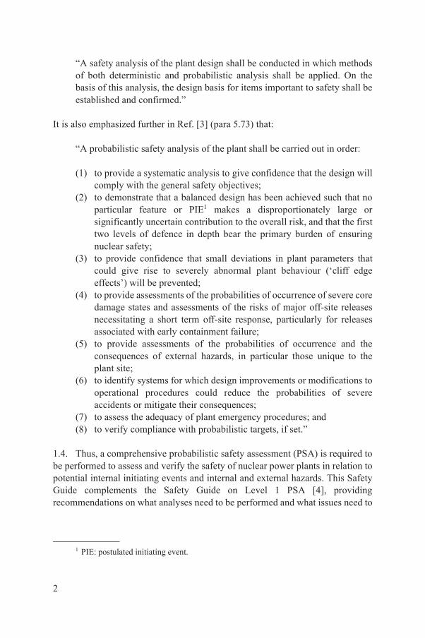
“A safety analysis of the plant design shall be conducted in which methods of both deterministic and probabilistic analysis shall be applied. On the basis of this analysis, the design basis for items important to safety shall be established and confirmed.”
It is also emphasized further in Ref. [3] (para 5.73) that:
“A probabilistic safety analysis of the plant shall be carried out in order:
(1) to provide a systematic analysis to give confidence that the design will comply with the general safety objectives;
(2) to demonstrate that a balanced design has been achieved such that no particular feature or PIE1 makes a disproportionately large or significantly uncertain contribution to the overall risk, and that the first two levels of defence in depth bear the primary burden of ensuring nuclear safety;
(3) to provide confidence that small deviations in plant parameters that could give rise to severely abnormal plant behaviour (‘cliff edge effects’) will be prevented;
(4) to provide assessments of the probabilities of occurrence of severe core damage states and assessments of the risks of major off-site releases necessitating a short term off-site response, particularly for releases associated with early containment failure;
(5) to provide assessments of the probabilities of occurrence and the consequences of external hazards, in particular those unique to the plant site;
(6) to identify systems for which design improvements or modifications to operational procedures could reduce the probabilities of severe accidents or mitigate their consequences;
(7) to assess the adequacy of plant emergency procedures; and(8) to verify compliance with probabilistic targets, if set.”
1.4. Thus, a comprehensive probabilistic safety assessment (PSA) is required to be performed to assess and verify the safety of nuclear power plants in relation to potential internal initiating events and internal and external hazards. This Safety Guide complements the Safety Guide on Level 1 PSA [4], providing recommendations on what analyses need to be performed and what issues need to
1 PIE: postulated initiating event.
2
be addressed to ensure that the Level 2 PSA meets the requirements on safety assessment established in Ref. [2].
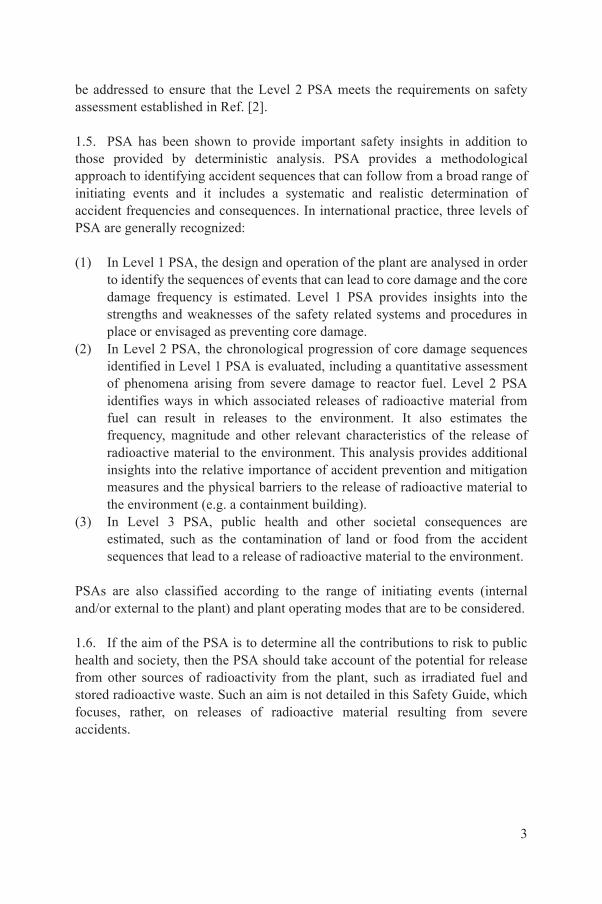
1.5. PSA has been shown to provide important safety insights in addition to those provided by deterministic analysis. PSA provides a methodological approach to identifying accident sequences that can follow from a broad range of initiating events and it includes a systematic and realistic determination of accident frequencies and consequences. In international practice, three levels of PSA are generally recognized:
(1) In Level 1 PSA, the design and operation of the plant are analysed in order to identify the sequences of events that can lead to core damage and the core damage frequency is estimated. Level 1 PSA provides insights into the strengths and weaknesses of the safety related systems and procedures in place or envisaged as preventing core damage.
(2) In Level 2 PSA, the chronological progression of core damage sequences identified in Level 1 PSA is evaluated, including a quantitative assessment of phenomena arising from severe damage to reactor fuel. Level 2 PSA identifies ways in which associated releases of radioactive material from fuel can result in releases to the environment. It also estimates the frequency, magnitude and other relevant characteristics of the release of radioactive material to the environment. This analysis provides additional insights into the relative importance of accident prevention and mitigation measures and the physical barriers to the release of radioactive material to the environment (e.g. a containment building).
(3) In Level 3 PSA, public health and other societal consequences are estimated, such as the contamination of land or food from the accident sequences that lead to a release of radioactive material to the environment.
PSAs are also classified according to the range of initiating events (internal and/or external to the plant) and plant operating modes that are to be considered.
1.6. If the aim of the PSA is to determine all the contributions to risk to public health and society, then the PSA should take account of the potential for release from other sources of radioactivity from the plant, such as irradiated fuel and stored radioactive waste. Such an aim is not detailed in this Safety Guide, which focuses, rather, on releases of radioactive material resulting from severe accidents.
3

1.7. Level 2 PSA is a structured process. Although there may be differences in the approaches for performing a Level 2 PSA, the general main steps are shown in Fig. 1 and are as follows:
(1) Level 1 PSA provides information on the accident sequences that lead to core damage and hence provides the starting point for the Level 2 PSA. The accident sequences identified by the Level 1 PSA may not include information on the status of the containment systems that mitigate the effects of severe accidents.
(2) The interface between Level 1 PSA and Level 2 PSA is where the accident sequences leading to core damage are grouped into plant damage states based on similarities in the plant conditions that determine the further accident progression. If the status of containment systems was not addressed in the Level 1 PSA, it needs to be considered by means of so-called ‘bridge trees’ of the interface between Level 1 PSA and Level 2 PSA or as the first step of the Level 2 PSA.
(3) Containment event tree analysis2 is where the accident progression is modelled to identify the accident sequences that lead to challenges to the containment and releases of radioactive material to the environment.
(4) Source term analysis is used to determine the quantities of radioactive material released to the environment from each of the release categories.
2 The term ‘accident progression event tree’ is also used by some practitioners for this part of the Level 2 PSA.
LEVEL 1 PSA LEVEL 1�2 INTERFACE LEVEL 2 PSA LEVEL 3
PSA
BRIDGE TREES CONTAINMENT
EVENT TREEANALYSIS
INIT
IAT
ING
EV
EN
TS
CO
RE
DA
MA
GE
SE
QU
EN
CE
S
SP
EC
IFIC
AT
ION
OF
PL
AN
T D
AM
AG
E S
TA
TE
S
GR
OU
PE
D P
LA
NT
DA
MA
GE
ST
AT
ES
RE
LE
AS
E C
AT
EG
OR
IES
SO
UR
CE
TE
RM
AN
AL
YS
IS/C
AT
EG
OR
IES
AN
AL
YS
IS O
F O
FF
-SIT
E C
ON
SE
QU
EN
CE
S
FIG. 1. General overview of the development of a typical Level 2 PSA.
4
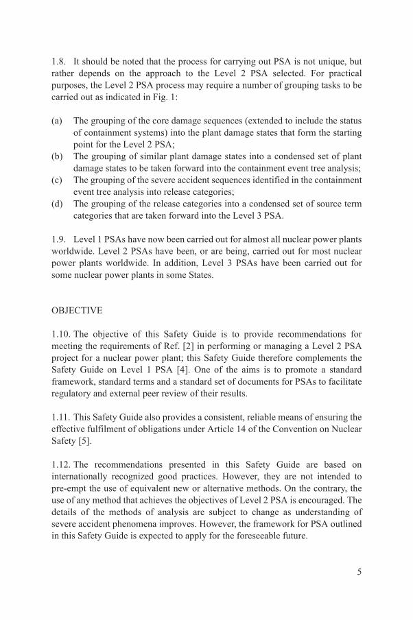
1.8. It should be noted that the process for carrying out PSA is not unique, but rather depends on the approach to the Level 2 PSA selected. For practical purposes, the Level 2 PSA process may require a number of grouping tasks to be carried out as indicated in Fig. 1:
(a) The grouping of the core damage sequences (extended to include the status of containment systems) into the plant damage states that form the starting point for the Level 2 PSA;
(b) The grouping of similar plant damage states into a condensed set of plant damage states to be taken forward into the containment event tree analysis;
(c) The grouping of the severe accident sequences identified in the containment event tree analysis into release categories;
(d) The grouping of the release categories into a condensed set of source term categories that are taken forward into the Level 3 PSA.
1.9. Level 1 PSAs have now been carried out for almost all nuclear power plants worldwide. Level 2 PSAs have been, or are being, carried out for most nuclear power plants worldwide. In addition, Level 3 PSAs have been carried out for some nuclear power plants in some States.
OBJECTIVE
1.10. The objective of this Safety Guide is to provide recommendations for meeting the requirements of Ref. [2] in performing or managing a Level 2 PSA project for a nuclear power plant; this Safety Guide therefore complements the Safety Guide on Level 1 PSA [4]. One of the aims is to promote a standard framework, standard terms and a standard set of documents for PSAs to facilitate regulatory and external peer review of their results.
1.11. This Safety Guide also provides a consistent, reliable means of ensuring the effective fulfilment of obligations under Article 14 of the Convention on Nuclear Safety [5].
1.12. The recommendations presented in this Safety Guide are based on internationally recognized good practices. However, they are not intended to pre-empt the use of equivalent new or alternative methods. On the contrary, the use of any method that achieves the objectives of Level 2 PSA is encouraged. The details of the methods of analysis are subject to change as understanding of severe accident phenomena improves. However, the framework for PSA outlined in this Safety Guide is expected to apply for the foreseeable future.
5
SCOPE
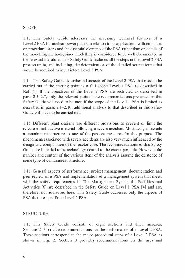
1.13. This Safety Guide addresses the necessary technical features of a Level 2 PSA for nuclear power plants in relation to its application, with emphasis on procedural steps and the essential elements of the PSA rather than on details of the modelling methods, since modelling is considered to be well documented in the relevant literature. This Safety Guide includes all the steps in the Level 2 PSA process up to, and including, the determination of the detailed source terms that would be required as input into a Level 3 PSA.
1.14. This Safety Guide describes all aspects of the Level 2 PSA that need to be carried out if the starting point is a full scope Level 1 PSA as described in Ref. [4]. If the objectives of the Level 2 PSA are restricted as described in paras 2.3–2.7, only the relevant parts of the recommendations presented in this Safety Guide will need to be met; if the scope of the Level 1 PSA is limited as described in paras 2.8–2.10, additional analysis to that described in this Safety Guide will need to be carried out.
1.15. Different plant designs use different provisions to prevent or limit the release of radioactive material following a severe accident. Most designs include a containment structure as one of the passive measures for this purpose. The phenomena associated with severe accidents are also very much influenced by the design and composition of the reactor core. The recommendations of this Safety Guide are intended to be technology neutral to the extent possible. However, the number and content of the various steps of the analysis assume the existence of some type of containment structure.
1.16. General aspects of performance, project management, documentation and peer review of a PSA and implementation of a management system that meets with the safety requirements in The Management System for Facilities and Activities [6] are described in the Safety Guide on Level 1 PSA [4] and are, therefore, not addressed here. This Safety Guide addresses only the aspects of PSA that are specific to Level 2 PSA.
STRUCTURE
1.17. This Safety Guide consists of eight sections and three annexes. Sections 2–7 provide recommendations for the performance of a Level 2 PSA. These sections correspond to the major procedural steps of a Level 2 PSA as shown in Fig. 2. Section 8 provides recommendations on the uses and
6

applications of a Level 2 PSA. Annex I gives an example of a typical schedule for the performance of a Level 2 PSA. Annex II discusses various types of computer code available for simulation of severe accidents and PSA studies. Annex III presents a sample outline of documentation for a Level 2 PSA.
2. PSA PROJECT MANAGEMENT AND ORGANIZATION
2.1. This section provides recommendations on meeting Requirement 22 of Ref. [2] on management of the safety assessment. The detailed aspects of project management and the organization of PSA set out in Section 3 of the Safety Guide on Level 1 PSA [4] are also applicable to Level 2 PSA and are not repeated here. Only those aspects that are particularly important for Level 2 PSA are presented in this section.
LEVEL 2 PSA
PROJECT MANAGEMENT AND
ORGANIZATION
(Section 2)
LEVEL 2 PSAIN
PU
T F
RO
M
LE
VE
L 1
PS
A
PL
AN
T
FA
MIL
IA
RIZ
AT
IO
N
(Sectio
n 3
)
SP
EC
IF
IC
AT
IO
N O
F
PL
AN
T D
AM
AG
E
ST
AT
ES
AC
CID
EN
T
PR
OG
RE
SS
IO
N
AN
AL
YS
IS
(Sectio
n 5
)
SO
UR
CE
TE
RM
AN
AL
YS
IS
(Sectio
n 6
)
OU
PU
T T
O
LE
VE
L 3
PS
A
DOCUMENTATION
OF LEVEL 2 PSA
(Section 7)
APPLICATION
OF LEVEL 2 PSA
(Section 8)
(S
ectio
n 4)
T
FIG. 2. Main steps in the performance of a Level 2 PSA.
7
DEFINITION OF THE OBJECTIVES OF LEVEL 2 PSA
2.2. Paragraphs 2.2–2.7 provide recommendations on meeting Requirement 4 of Ref. [2] on purpose of the safety assessment. A Level 2 PSA covers the progression of events that may occur in a nuclear reactor following an accident sequence that has led to significant damage to the reactor core (a severe accident). The main objective of the analysis is to determine if sufficient provisions have been made to manage a severe accident and mitigate the effects of such an accident. These provisions could include:
(a) Systems provided specifically to mitigate the effects of the severe accident, such as molten core retention features, hydrogen mixing devices or hydrogen recombiners, or filtered containment venting systems;
(b) The inherent strength of the containment structures or the capability for radioactive material retention within a confinement building, and the use for accident management of equipment provided for other purposes;
(c) Guidance to plant operators on severe accident management.
2.3. Performance of Level 2 PSA is a structured process as described in Section 1 and shown in Fig. 1. The scope of Level 2 PSA will be determined by its specific intended uses and by plans to carry out a Level 3 PSA. Although the basic framework and methods of Level 2 PSA are well established, the analysis in Level 2 PSA demands high levels of expertise and technical resources. Even when high levels of resources are employed, analyses of the containment and the radiological source terms are subject to large uncertainties associated with phenomena.
2.4. Differing end uses place differing emphases and requirements on the various inputs into, and components of, a Level 2 PSA. At the start of the project, the requirements for the Level 2 PSA should therefore be set out fully and it should be ensured that the user or recipient of the PSA understands these requirements and believes them to be realizable.
2.5. The overall objectives of the Level 2 PSA should be defined. These can include the following:
(a) To gain insights into the progression of severe accidents and the performance of the containment.
(b) To identify plant specific challenges and vulnerabilities of the containment to severe accidents.
(c) To provide an input into the resolution of specific regulatory concerns.
8

(d) To provide an input into determining compliance with the probabilistic safety goals, or with probabilistic safety criteria if these have been set. Typically, such probabilistic safety goals or criteria relate to large release frequencies and large early release frequencies.
(e) To identify major containment failure modes and their frequencies and to estimate the associated frequencies and magnitudes of radionuclide releases.
(f) To provide an input into the development of strategies for off-site emergency planning.
(g) To evaluate the impacts of various uncertainties, including uncertainties in assumptions relating to phenomena, systems and modelling.
(h) To provide an input into the development of plant specific accident management guidance and strategies.
(i) To provide an input into determining plant specific options for risk reduction.
(j) To provide an input into the prioritization of research activities for the minimization of risk significant uncertainties.
(k) To provide an input into Level 3 PSA consistent with the PSA objectives.(l) To provide an input into the environmental assessment of the plant.
Each of these objectives would place differing emphasis on one of the various aspects of the Level 2 PSA. The objectives reflecting the intended uses and applications of the Level 2 PSA should therefore be clearly specified at the beginning of the project.
2.6. The PSA model should be as realistic as possible. Appropriate consideration should be given to the significance of key uncertainties associated with phenomena. Care should be taken to avoid distorting the conclusions of the PSA through models and assumptions that are systematically biased towards particular outcomes (often for the sake of conservatism).
2.7. It should be noted that any limitations in the Level 1 PSA will be carried forward into the Level 2 PSA. This will need to be taken into account in the intended uses and applications of the Level 2 PSA.
SCOPE OF THE LEVEL 2 PSA
2.8. Paragraphs 2.8–2.11 provide recommendations on meeting Requirement 1 on graded approach and Requirement 14 relating to the scope of the safety analysis for a Level 2 PSA [2]. In undertaking a Level 2 PSA, there are two types
9

of situation likely to be encountered. In the first case, the Level 2 PSA is part of an integrated full scope PSA. In the second case, the Level 2 PSA is seeking to extend an existing Level 1 PSA. If the Level 2 PSA is performed as part of an integrated study, the requirements of the Level 2 PSA should be fed into the Level 1 PSA so that all plant related features that are important to the analysis of the containment response and source terms are considered wherever possible in the Level 1 PSA. If the Level 2 PSA is performed after the Level 1 PSA is complete, then some additional systems analysis may be necessary. In either case, in the linkage of the Level 1 and Level 2 PSA models, typically via the specification and quantification of plant damage states, it should be ensured that the Level 2 PSA takes fully into account the initial and boundary conditions from the Level 1 PSA model and the dependencies between the Level 1 PSA and the Level 2 PSA.
2.9. If the starting point is an existing Level 1 PSA, then its output may not explicitly cover all the features that need to be taken into account in the Level 2 PSA. Thus, if the objective of the Level 1 PSA was the quantification of core damage frequency, then the status of the containment and the containment safety systems may not have been directly addressed and therefore will have to be determined as part of the Level 2 PSA or as part of the modelling of the interface between Level 1 and Level 2 PSA (e.g. specification and quantification of the plant damage states).
2.10. If the scope of the PSA includes internal or external hazards (e.g. fire, earthquakes), their potential impact on the confinement function and the dependent failures they could cause should be taken into account as part of the Level 2 PSA, if they have not been previously taken into account in the Level 1 output. Examples of such dependent failures include failures in the containment isolation system due to cable fire, damage of containment structures due to seismic events, etc.
2.11. Finally, in determining the scope of the Level 2 PSA, consideration should be given to the input requirements for a Level 3 PSA, if one is contemplated. The ultimate product of a Level 2 PSA, then, will be a description of a number of challenges to the containment, a description of the possible containment responses and an assessment of the consequent releases to the environment and their associated frequencies. The description will include the inventory of material released, its physical and chemical characteristics, and information on the time, energy, duration and location of the releases.
10

PROJECT MANAGEMENT FOR PSA
2.12. Paragraphs 2.12–2.17 provide recommendations on meeting Requirement 5 of Ref. [2] on preparation for the safety assessment for Level 2 PSA. Information on the decisions that the PSA project managers should take and on the supervision, coordination and implementation of various tasks is provided in paras 3.3–3.14 of Ref. [4]. This information is also applicable to the Level 2 PSA and is not repeated here. One aim of project management for Level 2 PSA is to ensure that the PSA being produced does indeed represent the plant in its ‘as is’ condition and reflect realistic operating practices to the extent possible, and that it does take account of recent developments in methods, models and data.
2.13. In accordance with the requirements established in Ref. [6], a management system for the project should be implemented with due consideration given to the safety implications of the results of the Level 2 PSA and its intended uses. Owing to the complex phenomena addressed in Level 2 PSA and their associated uncertainties, as well as the extensive use of expert judgement and computational tools with limited resources for validation, the establishment of an adequate technical review system is of high importance (so as to meet Requirement 21 of Ref. [2] on independent verification). In particular, the application of expert judgment should be justified and managed through a controlled and documented process. Provisions should be made by the project management for establishing independent review processes or performing comparative studies, as appropriate. Further details on the specific needs for technical review of relevant aspects of the analysis, project documentation and configuration control are provided in Sections 3–7.
2.14. The production of a Level 2 PSA requires a high level of interaction between the analysts working on the analysis, who will offer a wide range of expertise. The project organization should provide working arrangements that ensure that there are good interactions and communication between all the members of the analysis team, including project managers and analysts. In addition, another objective of the overall management should be to ensure that, as the analysis progresses and insights are developed, the approaches to the different technical areas are modified as necessary to ensure that the analysis is progressing in a coherent way and that there is a reasonable balance of effort across all topics. The need to sustain good communication among the analysts during the entire PSA cannot be overemphasized.
11
2.15. The project management should aim to ensure that the insights gained from carrying out the analysis relating to plant vulnerabilities and severe accident management are properly understood by the plant management and operating staff, so that the operating organization gains ownership of the Level 2 PSA, and by the regulatory body or other relevant interested parties.
TEAM SELECTION
2.16. In the selection of the Level 2 PSA team, it should be ensured that there is an adequate level of expertise in the following areas: (i) knowledge of the design and operation of the plant, (ii) knowledge of severe accident phenomena and containment challenges, and (iii) knowledge of PSA techniques. The depth of the team’s expertise can be different depending on the stage in the lifetime of the plant at which the PSA is carried out, the scope of the PSA and the intended applications of the PSA, but extensive participation of the plant engineers and utility personnel, or designers if performed at the design stage, and probabilistic safety analysts specialized in accident phenomena and other Level 2 PSA disciplines is essential.
2.17. For a nuclear power plant at operation, the Level 2 PSA team should comprise:
(a) Operators and operational analysts: Specialists in the design and operation of the plant and key containment systems, the emergency operating procedures and the severe accident management guidelines.
(b) Specialists in phenomena: Specialists in severe accident phenomena, containment performance, uncertainties associated with severe accidents, chemical and physical processes governing accident progression, containment loads, releases of radionuclides and computer codes for the analysis of severe accidents.
(c) Structural specialists: Specialists in the structural design, the pressure capacity and the failure modes of the containment.
(d) Other PSA specialists: Specialists in event tree analysis, fault tree analysis, human reliability analysis, uncertainty analysis, statistical methods, processes for expert elicitation and judgement, PSA computer codes and Level 1 PSA.
12

3. IDENTIFICATION OF DESIGN ASPECTSIMPORTANT TO SEVERE ACCIDENTS AND
ACQUISITION OF INFORMATION
IDENTIFICATION OF DESIGN ASPECTS IMPORTANT TO SEVERE ACCIDENTS
3.1. This section provides recommendations on meeting Requirements 6–13 of Ref. [2] for Level 2 PSA. Before starting the analysis, the Level 2 PSA team should become familiar with the design and operation of the plant. The aim should be to identify and highlight plant systems, structures, components and operating procedures that can influence the progression of severe accidents, the containment response and the transport of radioactive material inside the containment. Design features that can influence the progression of a severe accident and Level 2 PSA include: fan coolers, containment sprays and/or filtered containment venting systems and suppression pools. This exercise should include the reactor building and/or the auxiliary building and the secondary containment or other relevant structures and buildings. For existing plants, familiarization with the plant should include a plant walk-through and should involve the participation of operating staff and engineers. The plant familiarization should involve all members of the Level 2 PSA team.
3.2. The specific plant features that can influence the progression of a severe accident should be identified and characterized. Examples of the features that need to be identified are as follows:
(a) The area under the reactor pressure vessel is important with regard to the behaviour of molten core material after it exits the bottom of the reactor pressure vessel, since the area influences the extent to which the molten core material will spread and its coolability.
(b) The flow paths from the area under the reactor pressure vessel to the main containment volume. Restrictions to the flow or other geometric aspects of the flow path will reduce the extent to which core debris is dispersed following a lower head failure. This is particularly important for high pressure melt ejection in a light water reactor.
(c) A highly compartmentalized containment configuration will limit the extent to which combustible gases mix and become distributed in the containment atmosphere.
(d) Features that could lead to containment bypass sequences.
13

These and other plant specific design features should be identified for further investigation.
3.3. Examples of key design features of the plant that are significant in respect of the progression and mitigation of severe accidents are listed in Table 1. In addition to plant features, relevant operating procedures and severe accident management guidelines should also be considered.
ACQUISITION OF INFORMATION IMPORTANT TO SEVERE ACCIDENT ANALYSIS
3.4. Paragraphs 3.4–3.6 provide recommendations on meeting Requirement 19 of Ref. [2] on use of operating experience data for Level 2 PSA. When the PSA team has developed a general understanding of the plant design and features that may influence severe accidents and releases of radioactive material, the quantitative data that are necessary to carry out the plant specific analysis should be collected and organized. The data necessary for the PSA depend in part on the scope of the analyses and the nature of the computational tools. For example, the amount and type of input data collected may depend on the plant specific computer model used to calculate accident progression. Detailed architectural and construction data for the containment structure should be collected to develop plant specific model calculations of the containment performance if such calculations are required by the scope of the containment performance analysis.
3.5. Data should be obtained from qualified sources, such as:
(a) Design documents and/or plant licensing documents;(b) As built drawings;(c) Plant specific operating, maintenance or test procedures;(d) Engineering calculations or analysis reports;(e) Observations during plant walkdowns;(f) Construction standards; (g) Vendor manuals.
References to the source(s) of data should be recorded as part of the PSA documentation.
14
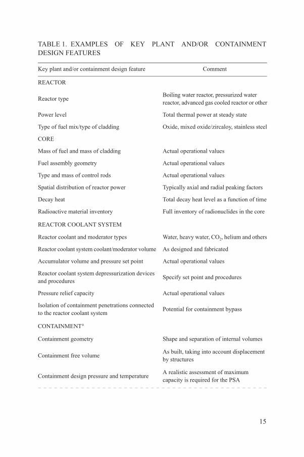
TABLE 1. EXAMPLES OF KEY PLANT AND/OR CONTAINMENT DESIGN FEATURES
Key plant and/or containment design feature Comment
REACTOR
Reactor typeBoiling water reactor, pressurized water reactor, advanced gas cooled reactor or other
Power level Total thermal power at steady state
Type of fuel mix/type of cladding Oxide, mixed oxide/zircaloy, stainless steel
CORE
Mass of fuel and mass of cladding Actual operational values
Fuel assembly geometry Actual operational values
Type and mass of control rods Actual operational values
Spatial distribution of reactor power Typically axial and radial peaking factors
Decay heat Total decay heat level as a function of time
Radioactive material inventory Full inventory of radionuclides in the core
REACTOR COOLANT SYSTEM
Reactor coolant and moderator types Water, heavy water, CO2, helium and others
Reactor coolant system coolant/moderator volume As designed and fabricated
Accumulator volume and pressure set point Actual operational values
Reactor coolant system depressurization devices and procedures
Specify set point and procedures
Pressure relief capacity Actual operational values
Isolation of containment penetrations connected to the reactor coolant system
Potential for containment bypass
CONTAINMENTa
Containment geometry Shape and separation of internal volumes
Containment free volumeAs built, taking into account displacement by structures
Containment design pressure and temperatureA realistic assessment of maximum capacity is required for the PSA
15
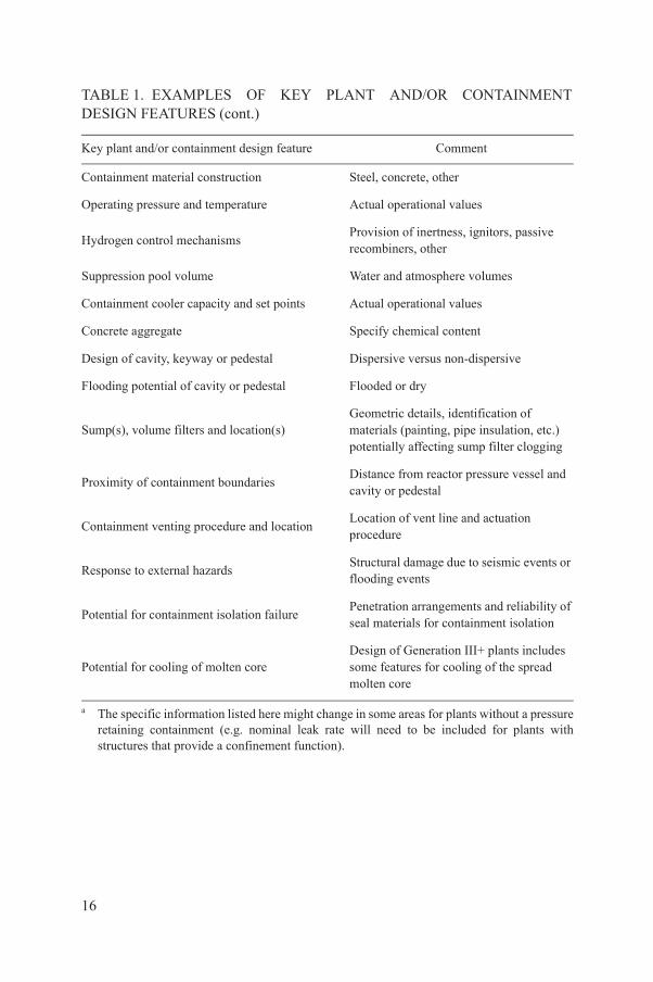
Containment material construction Steel, concrete, other
Operating pressure and temperature Actual operational values
Hydrogen control mechanismsProvision of inertness, ignitors, passive recombiners, other
Suppression pool volume Water and atmosphere volumes
Containment cooler capacity and set points Actual operational values
Concrete aggregate Specify chemical content
Design of cavity, keyway or pedestal Dispersive versus non-dispersive
Flooding potential of cavity or pedestal Flooded or dry
Sump(s), volume filters and location(s)Geometric details, identification of materials (painting, pipe insulation, etc.) potentially affecting sump filter clogging
Proximity of containment boundariesDistance from reactor pressure vessel and cavity or pedestal
Containment venting procedure and locationLocation of vent line and actuation procedure
Response to external hazardsStructural damage due to seismic events or flooding events
Potential for containment isolation failurePenetration arrangements and reliability of seal materials for containment isolation
Potential for cooling of molten coreDesign of Generation III+ plants includes some features for cooling of the spread molten core
a The specific information listed here might change in some areas for plants without a pressure retaining containment (e.g. nominal leak rate will need to be included for plants with structures that provide a confinement function).
TABLE 1. EXAMPLES OF KEY PLANT AND/OR CONTAINMENT DESIGN FEATURES (cont.)
Key plant and/or containment design feature Comment
16
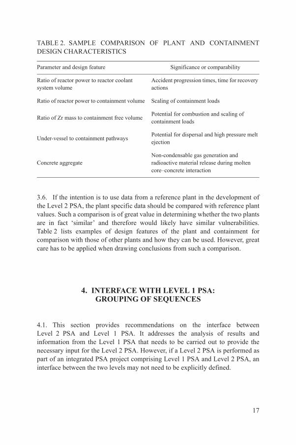
3.6. If the intention is to use data from a reference plant in the development of the Level 2 PSA, the plant specific data should be compared with reference plant values. Such a comparison is of great value in determining whether the two plants are in fact ‘similar’ and therefore would likely have similar vulnerabilities. Table 2 lists examples of design features of the plant and containment for comparison with those of other plants and how they can be used. However, great care has to be applied when drawing conclusions from such a comparison.
4. INTERFACE WITH LEVEL 1 PSA:GROUPING OF SEQUENCES
4.1. This section provides recommendations on the interface between Level 2 PSA and Level 1 PSA. It addresses the analysis of results and information from the Level 1 PSA that needs to be carried out to provide the necessary input for the Level 2 PSA. However, if a Level 2 PSA is performed as part of an integrated PSA project comprising Level 1 PSA and Level 2 PSA, an interface between the two levels may not need to be explicitly defined.
TABLE 2. SAMPLE COMPARISON OF PLANT AND CONTAINMENT DESIGN CHARACTERISTICS
Parameter and design feature Significance or comparability
Ratio of reactor power to reactor coolant system volume
Accident progression times, time for recovery actions
Ratio of reactor power to containment volume Scaling of containment loads
Ratio of Zr mass to containment free volumePotential for combustion and scaling of containment loads
Under-vessel to containment pathwaysPotential for dispersal and high pressure melt ejection
Concrete aggregateNon-condensable gas generation and radioactive material release during molten core–concrete interaction
17

4.2. Level 1 PSA identifies a large number of accident sequences that lead to core damage. It is neither practical nor necessary, in particular for PSA for full power conditions, to treat each accident sequence individually when assessing accident progression, containment response and radionuclide release in the Level 2 PSA. Accident sequences should be grouped together into plant damage states in such a manner that all accidents within a given plant damage state can be treated in the same way for the purposes of the Level 2 PSA. If necessary, the accident sequence models in the Level 1 PSA should be adjusted to take account of the specific needs of the Level 2 PSA. Plant damage states should represent groups of accident sequences that have similar accident timelines and which generate similar loads on the containment, thereby resulting in a similar event progression and similar radiological source terms. Attributes of accident progression that will influence the chronology of the accident, the containment response or the release of radioactive material to the environment should be identified. The attributes of the plant damage states provide boundary conditions for the performance of severe accident analysis.
PLANT DAMAGE STATES FOR PSA FOR INTERNAL INITIATING EVENTS FOR FULL POWER CONDITIONS
4.3. Generally, plant damage states can be classified into two main classes: those in which radioactive material is released from the reactor coolant system to the containment and those in which the containment is either bypassed or is ineffective. Thus, the plant damage states should specify the containment status (e.g. intact and isolated, intact and not isolated, failed or bypassed) and, for plant damage states where the containment is bypassed, should specify the type and size of the bypass (e.g. loss of coolant accident in interfacing systems, steam generator tube rupture). If the reactor building or secondary containment is likely to have a major influence on the source term, then its status is specified by means of the plant damage state. For plant damage states in which the containment is intact, a containment event tree analysis should be performed. For other plant damage states, only source term analysis may be necessary, although the containment event tree may be needed to address possible plant features that can reduce the source term (e.g. scrubbed releases versus unscrubbed releases).
4.4. The following subsections give examples of the attributes that may need to be taken into account in defining these two classes of plant damage states. Examples of such attributes are given in Table 3.
18
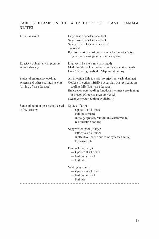
TABLE 3. EXAMPLES OF ATTRIBUTES OF PLANT DAMAGE STATES
Initiating event Large loss of coolant accident Small loss of coolant accident Safety or relief valve stuck openTransientBypass event (loss of coolant accident in interfacing system or steam generator tube rupture)
Reactor coolant system pressureat core damage
High (relief valves are challenged)Medium (above low pressure coolant injection head)Low (including method of depressurization)
Status of emergency cooling system and other cooling systems(timing of core damage)
All injection fails to start (no injection, early damage)Coolant injection initially successful, but recirculation cooling fails (later core damage)Emergency core cooling functionality after core damage or breach of reactor pressure vesselSteam generator cooling availability
Status of containment’s engineered safety features
Sprays (if any):— Operate at all times— Fail on demand— Initially operate, but fail on switchover to
recirculation cooling
Suppression pool (if any):— Effective at all times— Ineffective (pool drained or bypassed early)— Bypassed late
Fan coolers (if any):— Operate at all times— Fail on demand— Fail late
Venting systems:— Operate at all times— Fail on demand— Fail late
19

Plant damage states not initiated by bypass of the containment
4.5. In specifying plant damage states that are not initiated by bypass of the containment, account should be taken of the equipment and system failures identified in the Level 1 PSA that could affect either the challenge to the containment or the release of radioactive material. Aspects that should be taken into account include the following:
(a) Type of initiating event, which can, for example, affect the rate of discharge of fluid to the containment, the progression of the core melt and hydrogen generation, and the timing of the release of radioactive material.
(b) Failure mode of the core cooling function, which can affect the timing of the core melt.
(c) Extent of fuel damage.(d) The reactor circuit pressure at the onset of core damage and the status of
safety valves or relief valves and other components that could change the pressure in the reactor pressure vessel before failure of the lower head of the reactor pressure vessel. The pressure in the reactor pressure vessel at the time of lower head failure is important as it may influence the mode of discharge of debris to containment. This, in turn, could present a challenge to containment integrity if, for instance, high pressure melt ejection and direct containment heating ensue. The pressure in the reactor pressure vessel after the onset of core damage also influences the possibility of temperature and pressure induced failures of the reactor coolant system (e.g. creep rupture of piping and steam generator tubes, or thermal seizure of a safety or relief valve in the open position). The pressure will be influenced by the initiating event and the functionality of any depressurization system.
Containment status Intact and isolated at the onset of core damageIntact, but not isolated at the onset of core damageStructural failure or enhanced leakage (with indication of size and location of leakage)a
Status of secondary containment (reactor building or enclosure building)
Intact and isolated at the onset of core damageIntact, but not isolated at the onset of core damageStructural failure or enhanced leakagea
a This includes any external events that may damage containment structures.
TABLE 3. EXAMPLES OF ATTRIBUTES OF PLANT DAMAGE STATES (cont.)
20

4.6. The status of the containment’s engineered safety features3 is of high importance in determining the response of the containment and such safety features should be taken into account in the grouping of accident sequences into plant damage states, as they may influence containment cooling, the removal of radioactive material, the mixing of combustible gases present, etc. Other attributes of plant damage states may be important in some applications of PSA. For instance, if the PSA is being used to help determine accident management measures, then the status of the electrical power supply should be taken into account, since this information may be required for some later actions. The details of how these characteristics are taken into account may depend on the methodology used for linking the Level 1 and Level 2 PSAs, although these issues should be addressed irrespective of the methodology applied.
Plant damage states with bypass of the containment
4.7. For plant damage states with containment bypass, the main consideration should be the identification of attributes that are associated with attenuation of concentrations of radioactive material along the release pathway or affect the timing of release. This should include the type of initiating event, the status of the emergency core cooling system (including failure time) and whether the leak pathway is isolable after a period or whether it passes through water (e.g. steam generator inventory or flooded building). For leaks into the auxiliary building or an equivalent one, the status of emergency exhaust filtration systems, heating, ventilation and air conditioning, and whether or not the leak is submerged, could be significant and should be taken into account.
Final selection of plant damage states
4.8. If the consideration of all factors and parameters that affect the Level 2 PSA results in too large a number of potential plant damage states, then they should be reduced to a manageable number. Two approaches can be used. The first is to combine similar plant damage states and perform a bounding analysis to select a representative sequence that characterizes the plant damage state for the purpose of the Level 2 PSA. The second approach is to use a frequency cut-off as a means of screening out less important plant damage states. Careful screening is necessary prior to introducing a frequency cut-off criterion at the plant damage state level. This is especially true when dealing with plant damage states that
3 The attributes listed in Table 3 should be adjusted, as appropriate, for plants with structures that provide a confinement function rather than pressure retaining containments.
21

could involve large and early releases of radionuclides to the environment. In any case, in the selection process account should be taken of the degree of variability and uncertainty introduced in the Level 2 PSA by the grouping of accident sequences into plant damage states and consideration should be given to how this affects the specific objectives of the PSA.
PLANT DAMAGE STATES FOR AN EXISTING LEVEL 1 PSA
4.9. If the Level 2 PSA is an extension of a Level 1 PSA performed originally without the intention to perform a Level 2 or Level 3 PSA, specific aspects relevant to the specification of plant damage states are unlikely to have been considered in the Level 1 PSA. For example, the Level 1 PSA may not have addressed the status of containment systems or other systems that do not directly affect the determination of core damage (i.e. they do not contribute to the success criteria for preventing core damage). In such cases, the Level 1 PSA should be expanded to take into account the missing aspects in the specification of plant damage states (see Table 3 for reference). One method for incorporating such missing systems into the PSA is to develop bridge trees that link to Level 1 system models, as shown in Fig. 1, thereby capturing important dependencies (support systems, operator performance, etc.).
EXTENSION OF SCOPE OF LEVEL 2 PSA TO OTHER INITIATING EVENTS
4.10. In order to extend the scope of the Level 2 PSA to include internal and external hazards, their impact on systems necessary for mitigation of severe accidents, including systems that support operator actions, as well as the impact on containment integrity, should be taken into account. This could lead in some cases to the specification of a new set of distinct plant damage states, for example, for the case of earthquakes with the potential to induce containment failure. The system analyst should consider the need to introduce new plant damage states and possibilities for assimilating new plant damage states into existing ones; for instance some containment failures could be assimilated into containment isolation failures.
22

EXTENSION OF SCOPE OF LEVEL 2 PSA TO OTHER POWER STATES
4.11. Differences in the Level 2 PSA with respect to the mode of operation and power level when the initiating event occurs result primarily from differences in inventory and in the status of the primary circuit and the containment. The plant damage states specified for full power conditions should be used with care for low power and shutdown modes when the containment may be opened or not inerted; direct use of plant damage states specified for Level 2 PSA for full power conditions may not be possible. The unique conditions associated with low power and shutdown states generally necessitate the identification of additional attributes that are not applicable to full power operation.
4.12. Additional plant damage states should be specified for low power and shutdown states if there are significant differences that could have a major impact on plant behaviour in severe accidents or if there are other reasons for performing a more accurate representation of specific states. Some examples for pressurized water reactors include operation at mid-loop when the primary circuit inventory is low, or cases in which the primary circuit is open (e.g. during head removal or during refuelling) or the containment is not isolated (e.g. during some refuelling operations). Additional attributes that could be considered in the specification of plant damage states for low power and shutdown PSA include, therefore, the status of the containment and the level of the coolant.
5. ACCIDENT PROGRESSION ANDCONTAINMENT ANALYSIS4
ANALYSIS OF CONTAINMENT PERFORMANCE DURING SEVERE ACCIDENTS
5.1. This section presumes the existence of some type of passive structure with the capability to withstand some of the conditions resulting after severe damage to the reactor core and thus retaining a large portion of the radioactive material.
4 This section addresses several key parts of a Level 2 PSA. The order in which they are presented here is not an indication of their relative importance or the order in which they should be carried out within a PSA project.
23

The most common version of such a passive structure in many plant designs is a containment building, which includes associated containment systems. Where such a structure does not exist, the analysis described in the following is not entirely applicable.
5.2. The primary objective of an assessment of containment performance is to develop a realistic characterization of the modes (mechanisms) of, and criteria for, containment leakage or failure under severe accident conditions. Design criteria for the containment are generally not adequate measures of capacity of the containment because of the safety factor built into such values. Actual values of the ultimate pressure capacity of the containment have sometimes been found to exceed design values by a factor of two to four. Further, containment design limits may not take into account the harsh environmental conditions that can develop inside the containment during a severe accident, which often require consideration of entirely new failure modes.
5.3. To generate a realistic assessment of containment performance limits, detailed information on the structural design of the containment and containment penetrations (see Table 4) should be collected. In the collection of information for the analysis, particular consideration should be given to the potential for leakage through a steel liner or penetrations.
TABLE 4. EXAMPLES OF IMPORTANT FEATURES OF THE STRUCTURAL DESIGN OF THE CONTAINMENT AND CONTAINMENT PENETRATIONS
Containment type SteelConcrete:
— Prestressed— Post-tensioned— Reinforced
Containment penetrations Equipment hatch(es)Personnel hatch(es)Piping penetrationsElectrical penetrationsAtmosphere purge line(s)Vent line(s)
Other aspects Geometrical shape of containment (sphere, cylinder, rectilinear)Geometrical discontinuities, e.g. transition from cylindrical shell to top head and basematLiner anchoragesInteractions with other surrounding structures
24

5.4. This step of the Level 2 PSA is aimed at developing a plant specific estimate of the ultimate strength of the containment. This can be done by carrying out plant specific structural calculations. However, depending on the scope of the Level 2 PSA study, use can be made of existing calculations for plants having similar containment designs. In this case, the PSA documentation should provide a thorough justification for the use of existing calculations, by demonstrating the similarities of the designs and the applicability of the existing structural response analyses to the plant under consideration.
5.5. Two basic approaches have been used in PSA studies to characterize the loss of containment integrity, namely, the ‘threshold’ model and the ‘leak before break’ model. The threshold model defines a threshold pressure, with some associated uncertainties, at which the containment is expected to fail, with a large rupture and with the potential for significant and rapid blowdown of the containment atmosphere to the environment. In the leak before break model, containment leakage is expected to precede a major rupture. In general, leakage begins at pressures below the ultimate capability pressure and progressively increases up to the ultimate capability pressure, at which point a larger failure of the containment is expected to occur. Furthermore, if the rate of addition of mass and energy to the containment atmosphere is smaller than or equal to the leakage rate, containment pressurization is not expected to occur and massive failure of the containment could be averted.
5.6. If plant specific calculations are necessary, containment performance analyses should be based on validated structural models supported by data and reasonable failure criteria. In the analysis, consideration should be given to various types of load on the containment, e.g. static pressure loads, pressure ramp rates, localized heat loads and localized dynamic pressure loads. The supporting analyses provide an engineering basis for containment failure mode, location, size and ultimate pressure and/or temperature capabilities.
5.7. While internal pressure loading is the principal determinant of potential containment failure, consideration should also be given in the Level 2 PSA to the possible effects of temperature on the structural performance of containment. The temperature of the containment could affect the strength characteristics of the structural materials as well as cause degradation of penetration seal materials.
5.8. In determining the structural performance of the containment, the uncertainties associated with estimation of the structural capacities necessary for withstanding extremes of pressure and/or temperature should also be assessed. Such uncertainties can be determined by techniques for uncertainty quantification
25
and propagation, as part of the structural capacity assessment. Alternatively, expert judgement supported by simple analysis could be used to establish the failure pressure and/or temperature distribution for various credible failure modes (leaks and ruptures). In the uncertainty assessment and in modelling the propagation of uncertainties, account should be taken of uncertainties in the properties of materials and in modelling (e.g. criteria used to define ‘failure’).
5.9. The effects of extensive erosion of concrete structures due to long term exposure and to attack by molten core debris (molten core–concrete interactions) should be examined. For example, the response of a reactor pressure vessel support structure (e.g. concrete pedestal), containment wall or floor to the complete or partial penetration by core debris should be examined if calculations of severe accident progression suggest such levels of erosion are possible.
5.10. Potential locations for melt through of the containment (e.g. penetrations, sump suction lines) should be identified and analysed.
ANALYSIS OF THE PROGRESSION OF SEVERE ACCIDENTS
5.11. Plant specific analysis of the progression of accidents is the preferred method for evaluating severe accident behaviour. As a minimum, calculations should be performed for each of the plant damage states that are significant contributors to the core damage frequency of the plant. In addition, calculations could also be performed for those plant damage states that may have a small frequency of occurrence, but which have the potential to result in large and/or early releases of radioactive material to the environment. Such plant damage states typically involve either direct containment bypass or early failure of the primary and/or secondary containments. If detailed calculations are performed for plant damage states with high frequency of occurrence and high consequences, a sufficiently wide range of information will usually be generated to estimate the response of the plant for other plant damage states that are not addressed in detail. In addition, generic studies of severe accident phenomena and containment response reported in the literature for similar plants and containments could also be used to complement the scope of plant specific calculations to include a broader set of conditions.
5.12. A less rigorous and less appropriate approach, but one which is occasionally necessary, is to adapt the results of analyses for one or more reference plants of a similar design. This approach should be carried out only by exercising extreme caution. In such circumstances, the uncertainties associated
26

with the progression of severe accidents can outweigh the differences in plant specific design aspects. Small differences in plant design features can be accommodated by appropriate scaling of the reference plant analyses with regard to key design attributes. This approach is most appropriate where a special analysis of key phenomena has been performed for a reference plant and it is desired to take insights from the reference analysis to supplement plant specific calculations. For example, such an analysis for one plant may have addressed an accident phenomenon that is not modelled in detail by the commonly used computer codes for severe accident simulation, and in this case scaling or adapting the reference analysis provides additional useful input into the plant specific evaluation.
5.13. The analysis of the progression of severe accidents should be performed using one or more computer codes for severe accident simulation (see Annex II). The computer code(s) chosen to perform detailed analysis and the number of calculations that should be performed depends on the objective of the PSA. Among the issues that should be considered in making these decisions are:
(a) The code(s) should be capable of modelling most of the events and phenomena that may appear in the course of the accident.
(b) Interactions between various physicochemical processes should be correctly addressed in the computer code.
(c) The extent of validation and benchmarking effort and associated documentation should be satisfactory.
(d) Computing time and resource requirements should be reasonable.
The analysts should be aware of the technical limitations and weaknesses of the selected code(s). The analyses of severe accidents should cover all sequences leading either to a successful stable state, where sufficient safety systems have operated correctly so that all the required safety functions necessary to cope with the plant damage state have been fulfilled, or to a containment failure state.
5.14. Sensitivity analyses should be performed to understand how the various modelling options within a code affect calculated results. Known areas of modelling uncertainty with potential implications on the modelling of severe accident progression are listed in Table 5.
5.15. The key variables calculated (such as peak pressures and temperatures, mass of combustible gas generated, timing of major events) must be assessed and documented for use in the models for quantification of accident progression (containment event tree) addressed in paras 5.16–5.31. Key variables are
27

TABLE 5. EXAMPLES OF AREAS OF UNCERTAINTY RELEVANT TO THE PROGRESSION OF SEVERE ACCIDENTS
Type of severe accident event Related phenomena
In-vessel hydrogen generation Formation of flow blockages in core‘Ballooning’ of claddingRecovery and addition of water Relocation of molten fuel
In-vessel natural circulation Circulation flows in reactor coolant system loops Heat-up and creep rupture of reactor coolant system pressure boundary (hot leg nozzle, pressurizer surge line and steam generator tubes)Competing mechanisms of degradation and failure of reactor coolant pump seal
In-vessel fuel–coolant interactions (energetic and non-energetic)
Potential for terminating damage to in-vessel fuelRecriticalityExplosive failure of reactor pressure vesselReleases of radioactive material
Failure mechanisms of reactor pressure vessel
Melt penetration and cooling within head penetrationsLocal failure of lower head of reactor pressure vesselGlobal (creep) failure of reactor pressure vessel
High pressure melt ejection and/or direct containment heating
Trapping of debris on containment structuresHeat release on hydrogen generation from zirconium oxidationDebris transport outside of cavity and/or pedestalHydrogen combustionReleases of radioactive material
Ex-vessel fuel–coolant interactions (energetic and non-energetic)
Debris fragmentation and quench (cooling) Quasi-static increase in containment pressure (steam spike)Dynamic loads to containment from steam explosionReleases of radioactive material
28
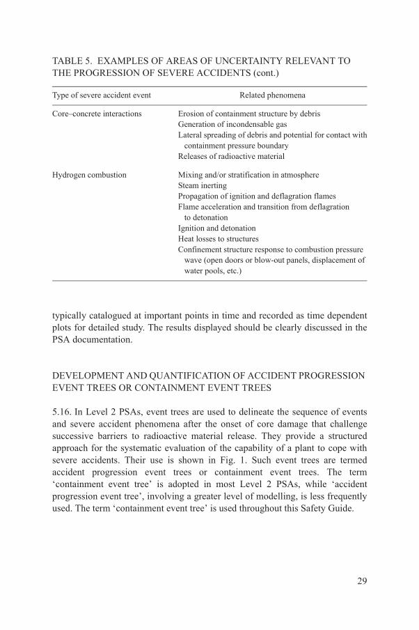
typically catalogued at important points in time and recorded as time dependent plots for detailed study. The results displayed should be clearly discussed in the PSA documentation.
DEVELOPMENT AND QUANTIFICATION OF ACCIDENT PROGRESSION EVENT TREES OR CONTAINMENT EVENT TREES
5.16. In Level 2 PSAs, event trees are used to delineate the sequence of events and severe accident phenomena after the onset of core damage that challenge successive barriers to radioactive material release. They provide a structured approach for the systematic evaluation of the capability of a plant to cope with severe accidents. Their use is shown in Fig. 1. Such event trees are termed accident progression event trees or containment event trees. The term ‘containment event tree’ is adopted in most Level 2 PSAs, while ‘accident progression event tree’, involving a greater level of modelling, is less frequently used. The term ‘containment event tree’ is used throughout this Safety Guide.
Core–concrete interactions Erosion of containment structure by debrisGeneration of incondensable gas Lateral spreading of debris and potential for contact with containment pressure boundaryReleases of radioactive material
Hydrogen combustion Mixing and/or stratification in atmosphereSteam inertingPropagation of ignition and deflagration flames Flame acceleration and transition from deflagration to detonation Ignition and detonationHeat losses to structuresConfinement structure response to combustion pressure wave (open doors or blow-out panels, displacement of water pools, etc.)
TABLE 5. EXAMPLES OF AREAS OF UNCERTAINTY RELEVANT TO THE PROGRESSION OF SEVERE ACCIDENTS (cont.)
Type of severe accident event Related phenomena
29

Structure of containment event trees and nodal questions
5.17. The top events or nodal questions in a containment event tree should address the events and physical processes that govern accident chronology, plant response to beyond design basis conditions, relevant challenges to barriers to radioactive material release and the eventual magnitude of the release of radioactive material to the environment. Nodal questions of the containment event tree should also address issues and actions relating to severe accident management (see also paras 5.19 and 5.20). The nodal questions of the containment event tree are strongly specific to plant type, i.e. issues of importance to severe accident behaviour in one type of reactor and/or containment system may not be important to others.
5.18. The list of such events and processes can be rather extensive. Therefore, containment event trees can grow to become rather large and complicated logic models. However, relatively simple logic models can be sufficient for certain applications. Thus, for instance, if the objective of the Level 2 PSA is solely to determine the large early release frequency and a quantitative assessment of the full range of severe accident source terms is not required, smaller containment event tree structures can be developed that focus on severe accident sequences with high consequences within the appropriate time frame. In any case, the overall structure of the model should be traceable by independent reviewers and manageable by the PSA team. Therefore, in the containment event tree structures, a reasonable balance between modelling detail and practical size should be achieved.
5.19. The containment event tree structure should be chronologically correct, should properly take into account interdependencies among events and/or phenomena and should reflect an appropriate level of detail to satisfy the objectives of the Level 2 PSA. Regarding chronology, it is both useful and common practice to divide the containment event tree into phases sequential in time, with the transitions between phases representing important changes in the issues that govern accident progression, such as:
(a) Phase 1: Immediate response of the plant to the plant damage state caused by the initiating event through the early period of in-vessel core damage.
(b) Phase 2: Late period of in-vessel core damage up to failure of the reactor pressure vessel.
(c) Phase 3: Long term response of the plant.
5.20. Phase 3 is sometimes further subdivided into three subphases: (i) phase 3a — close to the time of reactor pressure vessel failure (to address challenges
30

occurring due to failure of the reactor pressure vessel, e.g. direct containment heating); (ii) phase 3b — up to a few hours after failure of the reactor pressure vessel (to address immediate ex-vessel molten core behaviour, e.g. stabilization of the melt ex-vessel or onset of the core–concrete interaction); and (iii) phase 3c — long term, starting from a few hours after failure of the reactor pressure vessel (to address challenges arising from ex-vessel melt behaviour, e.g. pressurization due to the generation of non-condensable gases during core–concrete interaction or combustion phenomena or pressurization due to ongoing steam generation). Examples of a typical structure and nodal questions of a containment event tree for a typical pressurized water reactor with a large, dry containment are provided in Table 6.
Accident recovery or actions for severe accident management and equipment issues
5.21. Actions for severe accident management should be reflected in the Level 2 PSA. Typically, the human actions credited in PSA are included in plant procedures and severe accident management guidelines. Manual actions that are demanded soon after the onset of core damage can be represented in the accident sequence event trees in the Level 1 PSA model, if the conditions for their implementation can be predicted with confidence. In such cases, the status of such manual actions (success or failure) must be reflected either explicitly by the use of an attribute of a plant damage state which indicates this status or implicitly via their impact on the status of other attributes already defined for the plant damage state. Relevant severe accident management actions that are not represented in the Level 1 model should be incorporated into the containment event trees. Typically, such actions would be those which are expected later in the chronology of the severe accident sequence, for example, refilling of steam generators to reduce releases to the environment via damaged steam generator tubes and restarting the low pressure injection after a high temperature induced break in primary circuit boundaries. In turn, the results of the Level 2 PSA can, and should, be used to identify or improve severe accident management actions as explained in Section 8.
5.22. It is important to ensure that potential dependencies between operator actions included in the accident sequence models in Level 1 PSA and in the containment event trees for Level 2 PSA are assessed and taken into account, as appropriate. The probabilistic treatment of manual actions should be consistent with the Level 1 PSA. Dependencies relating to system availability should also be correctly taken into account.
31

TABLE 6. EXAMPLES OF NODAL QUESTIONS FOR A CONTAINMENT EVENT TREE FOR A PRESSURIZED WATER REACTOR
Top event questionPrior
dependenciesQuestion type
Phase 1: Initiating event through to early periodof in-vessel core damage
1 Is the containment isolated? None Based on plantdamage state
2 What is the fraction of the plant damage state withAC power available?
None Based on plantdamage state
3 What is the mechanical status of sprays in the veryearly time frame?
None Based on plantdamage state
4 What is the mechanical status of fans in the veryearly time frame?
None Based on plantdamage state
5 Is the reactor coolant system depressurized manuallyin the very early time frame?
2 Based on emergency operating procedures
6 Does a temperature induced ‘hot leg’ failure occurin the very early time frame?
5 Accidentprogression
7 Does a temperature induced rupture of a steam generatortube occur in the very early time frame?
5, 6 Accident progression
8 Is AC power restored or maintained in the very earlytime frame?
2 Based on plant damage state
9 Are sprays actuated in the very early time frame? 3, 6, 8 Accident progression
10 Does hydrogen combustion occur in the very earlytime frame?
4, 5, 6, 8, 9 Accident progression
11 Does the containment fail in the very early timeframe?
1, 10 Accident progression
32
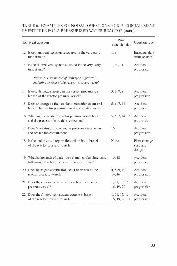
12 Is containment isolation recovered in the very earlytime frame?
1, 8 Based on plant damage state
13 Is the filtered vent system actuated in the very earlytime frame?
1, 10, 11 Accident progression
Phase 2: Late period of damage progression, including breach of the reactor pressure vessel
14 Is core damage arrested in the vessel, preventing abreach of the reactor pressure vessel?
5, 6, 7, 8 Accident progression
15 Does an energetic fuel–coolant interaction occur and breach the reactor pressure vessel and containment?
5, 6, 7, 14 Accident progression
16 What are the mode of reactor pressure vessel breachand the process of core debris ejection?
5, 6, 7, 14, 15 Accident progression
17 Does ‘rocketing’ of the reactor pressure vessel occurand breach the containment?
16 Accident progression
18 Is the under-vessel region flooded or dry at breachof the reactor pressure vessel?
None Plant damage state and design
19 What is the mode of under-vessel fuel–coolant interaction following breach of the reactor pressure vessel?
16, 18 Accident progression
20 Does hydrogen combustion occur at breach of thereactor pressure vessel?
4, 8, 9, 10,14, 16
Accident progression
21 Does the containment fail at breach of the reactorpressure vessel?
1, 11, 13, 15,16, 19, 20
Accident progression
22 Does the filtered vent system actuate at breachof the reactor pressure vessel?
1, 11, 13, 15,16, 19, 20, 21
Accident progression
TABLE 6. EXAMPLES OF NODAL QUESTIONS FOR A CONTAINMENT EVENT TREE FOR A PRESSURIZED WATER REACTOR (cont.)
Top event questionPrior
dependenciesQuestion type
33

5.23. The effect of the environmental conditions resulting from a severe accident on the survivability of components and systems credited within the Level 2 PSA model should also be assessed and, as appropriate, taken into account. Environmental impacts may include temperature, pressure, humidity and radiation conditions, as well as effects derived from energetic events (e.g. short
Phase 3: Long term response of the plant
23 Is AC power restored or maintained in the late time frame?
8 Based on plant damage state
24 Do sprays actuate or continue to operate in the late time frame?
23, 9 Plant damage state/accident progression
25 Do fan coolers actuate or continue to operate in the late time frame?
4, 8 Based on plant damage state
26 What is the status of fans and sprays in the late time frame?
24, 25 Summary type question
27 Is core debris in a coolable configuration outside the vessel?
16, 18, 19,15, 17
Accident progression
28 Does hydrogen combustion occur in the late time frame? 10, 20, 26 Accident progression
29 Does containment failure occur in the late time frame? 1, 10, 11, 13,15, 21, 26,20, 28, 19
Accident progression
30 Does the filter vent system actuate in the late time frame? 1, 10, 11, 13,15, 19, 20,21, 26, 28, 27
Accident progression
31 Is the integrity of the containment basemat maintained? 11, 12, 21, 22,27, 29, 31
Accident progression
32 What are the modes of containment failure? 11, 21, 29 Accident progression
TABLE 6. EXAMPLES OF NODAL QUESTIONS FOR A CONTAINMENT EVENT TREE FOR A PRESSURIZED WATER REACTOR (cont.)
Top event questionPrior
dependenciesQuestion type
34
term temperature and pressure spikes or impulse loadings from detonations or steam explosions).
5.24. Potential adverse effects of severe accident management actions should also be considered as part of the event tree logic. For instance, injection of water into a degraded core may be able to arrest the progression of a severe accident. However, there is also the potential for energetic fuel–coolant interaction, fuel shattering and additional releases of steam, hydrogen and radioactive material.
Quantification process for containment event trees
5.25. The assignment of conditional probabilities to branches of the containment event tree should be supported by documented analyses and data to provide a justified representation of the uncertainty in the outcome at each node. Account should be taken of issues that could affect the analyst’s ability to predict the progression of severe accidents, including completeness, fidelity and validation of available computer codes, applicability of available experimental data to full scale reactor conditions, etc. Example methods for dealing with such uncertainties can be found in Refs [7–10].
5.26. The rationale used to develop appropriate probabilities for each branch can sometimes be made more traceable by decomposing the problem into a number of sub-issues according to the governing phenomena [11, 12]. Such assessments may be carried out separately and reported in support documentation of the results that are used in the nodal questions of the containment event tree or may be an integral part of the containment event tree in the form of decomposition event trees that are linked to the headings of the containment event tree. The degree to which the assessments are integrated into the quantification of the containment event tree is principally dependent on the capabilities of the software being used for quantification of the Level 2 PSA. Linked event trees, fault trees (see e.g. Ref. [13]), user defined functions and other methods have been used for developing and quantifying containment event trees.
5.27. Regardless of the approach taken to develop values for the probabilities of events, the process should be traceable so that others can follow and understand the technical rationale, and it should be applied consistently to the full range of events or questions described in the containment event tree. Several sources of current and relevant information can be used to support the assignment of probabilities, such as:
35
(a) Deterministic analyses using established computer codes for modelling severe accidents or basic principles;
(b) Relevant experimental measurements or observations; (c) Analyses and findings from studies of similar plants; (d) Expert elicitation involving independent experts.
5.28. Several methods and tools are available to translate such information into a numerical value for each probability. Two simple tools, the threshold approach and the integral approach, are briefly described in this Safety Guide. Reference [14] has historically been a key source of information for many Level 2 PSAs. However, the state of knowledge of severe accident phenomena has progressed since the Ref. [14] study, thus reducing its usefulness as a reference for modern Level 2 PSA studies, which should reflect the current state of knowledge. A compilation of recent, relevant severe accident phenomena can be found in Refs [15, 16]. Developments have taken place in a number of areas, such as:
(a) In-vessel steam explosions (alpha mode containment failure), e.g. Ref. [11];(b) Direct containment heating, e.g. Ref. [17]; (c) Failure of the lower head of the reactor pressure vessel, e.g. Refs [18, 19];(d) Flame acceleration and the transition from deflagration to detonation, e.g.
Ref. [20].
Threshold approach
5.29. The threshold approach can be used to estimate the probabilities of events that occur when the predicted accident conditions approach an established limit or criterion. The failure probability is, therefore, a function of ‘how close’ the parameter is to the failure threshold. The assignment of numerical values is thus indicative of the analyst’s confidence in the rigour, applicability and completeness of deterministic predictions of relevant phenomena.
Integral approach
5.30. In the integral approach, a higher degree of mathematical rigour is applied to the comparison of how close the parameter of interest (pressure, temperature, etc.) is to the failure threshold (failure pressure, failure temperature, etc.). Both the parameter of interest and the failure threshold are treated as uncertain parameters. Probability density functions representing probability distributions of uncertain parameters are arrived at on the basis of deterministic analyses and expert judgement, and the overlap and/or interference of two such probability
36

distributions determines the degree of ‘belief’ in (the subjective probability for) failure. In this case, the consistency of the resulting probability values is dependent on consistent assignment of distribution parameters (median values, deviations about the median, choice of distribution type and limits).
5.31. Both approaches, the threshold approach and the integral approach, can be applied either individually or in combination in the PSA. In any case, for ensuring that probabilities are derived in a consistent manner across the wide range of events and phenomena evaluated in the Level 2 PSA, a set of rules should be developed and included in the PSA documentation. Such rules should include the rationale used to assign particular probabilistic estimates.
TREATMENT OF UNCERTAINTIES
5.32. Paragraphs 5.32–5.42 provide recommendations on meeting Requirement 17 of Ref. [2] on uncertainty and sensitivity analysis for Level 2 PSA. Uncertainty arises in a Level 2 PSA analysis as a result of several factors, including:
(1) Incompleteness uncertainty. The overall aim of a Level 2 PSA is to assess the possible scenarios (sequences of events) that can lead to releases of radionuclides, mainly those scenarios modelled in the Level 1 PSA. However, there is no guarantee that this process can ever be complete and that all possible scenarios have been identified and properly assessed. This potential lack of completeness introduces an uncertainty in the results and conclusions of the analysis that is difficult to assess or quantify. It is not possible to address this type of uncertainty explicitly. However, extensive peer review can reduce this type of uncertainty.
(2) Loss of detail due to aggregation. Grouping accident sequences or cutsets from the Level 1 PSA into plant damage states for input into the Level 2 PSA for practical reasons also introduces uncertainties due to the resulting loss of some modelling detail. Further, the process of ‘binning’ (or grouping) accident sequences introduces uncertainty through the possibility that the attributes used by the analyst to group ‘similar’ accident sequences are incomplete. These elements of uncertainty are also difficult or impossible to quantify, but which will diminish over time as increases in computing resources allow increasing levels of detail to be captured in the PSA.
37

(3) Modelling uncertainty. This arises due to a lack of complete knowledge concerning the appropriateness of the methods, models, assumptions and approximations used in the individual analysis tasks that support a Level 2 PSA. Modelling uncertainties are formally addressed as part of the uncertainty treatment in the Level 2 PSA (see paras 5.33–5.40).
(4) Parameter uncertainty. This arises due to the uncertainties associated with the values of the fundamental parameters used in the quantification of the Level 2 PSA, such as equipment failure rates and initiating event sequences. This is the type of uncertainty that is usually addressed by an uncertainty analysis through specifying uncertainty distributions for all the parameters and propagating them through the analysis.
Items (1) and (3) above are usually referred to as epistemic uncertainties (i.e. uncertainties due to lack of knowledge). Aleatory (randomness) uncertainties may also be present in some events in the Level 2 PSA.
5.33. Since Level 2 PSA analysts use probabilities in the containment event trees to reflect confidence that particular choices of modelling parameters or event outcomes are the correct ones, the Level 2 PSA is in some sense directly concerned with the treatment of uncertainties, which is therefore one of the most important aspects of the analysis.
5.34. The Level 2 PSA analysts should identify the dominant sources of uncertainty in the analysis and should quantitatively characterize the effects of these uncertainties on the baseline (point estimate) results. This is typically accomplished using two methods: (i) sensitivity analysis and (ii) uncertainty analysis.
5.35. Whereas sensitivity analysis is used to measure the extent to which results would change if alternative models, hypotheses or values of input parameters were selected (and thus provides an evaluation of uncertainty in respect of a particular issue or a particular group of related issues at a time), uncertainty analysis examines a range of alternative models or parameter values, assigns each model or value a probability and generates a distribution of the results, within which the baseline results represent one possible outcome. Each result within the full distribution is accompanied by a (subjective) probability representing the degree of belief in that result. Cumulative probability levels for the results can be calculated (e.g. the 5th, 50th and 95th percentiles represent 5%, 50% and 95% probabilities, respectively, and the ‘true’ result is below the respective level for which each of these probabilities is stated). In general, the process of
38

quantification and propagation of uncertainties in the Level 2 PSA can be divided into four principal steps as set out in paras 5.36–5.42.
(1) Specification of the scope of the uncertainty analysis
5.36. The sources of uncertainty in a Level 2 PSA are numerous and it is impractical to address all of them quantitatively. Experience in performing uncertainty studies for limited aspects of severe accident phenomena suggests that the effects of uncertainties from some sources are larger and more dominant than the effects of uncertainties from other sources. In an integral sense, then, the aggregate uncertainty in Level 2 PSA results can be estimated by selecting the dominant sources of uncertainty and treating them in detail. Reference [10] provides information on an evaluation of uncertainties in relation to severe accidents and Level 2 PSA.
5.37. Sensitivity analysis is a useful tool to guide the selection of dominant sources of uncertainty. Example areas of uncertainty related to the progression of severe accidents are listed in Table 5.
(2) Characterization and/or evaluation of uncertainty issues
5.38. After the definition of the scope of the analysis, the second step is to identify the range of values of uncertain parameters. Each value within the range of values that the uncertain parameter can take on is associated with a probability, thereby creating a probability density function or probability distribution. In many cases, such density functions or probability distributions will have been determined in the assessment of probabilities for branch points in the containment event tree. Additional parameters that may also be characterized or evaluated by means of probability distributions may be, for example, source term calculation parameters not explicitly addressed in the containment event tree.
5.39. Judgements reflected in the probability distributions for each parameter should be supported by data, analyses and consideration of the published literature. In addition, the probability distributions of uncertain parameters should be peer reviewed as part of the PSA study.
(3) Propagation of uncertainties
5.40. The propagation of uncertainties through the analysis can also be accomplished using various methods, depending on the objective of the uncertainty analysis. Examples of available propagation techniques include:
39

(i) the use of discrete probability distributions and (ii) direct simulation methods based on either simple (Monte Carlo) random sampling or stratified (Latin hypercube) sampling procedures, which are primarily used nowadays. Additional details can be found in Refs [7, 14, 21–25].
(4) Display and interpretation of results
5.41. The results of the uncertainty analysis should be carefully evaluated to strengthen the conclusions of the Level 2 PSA. In modern PSAs that include a quantitative assessment and propagation of uncertainties, the results are displayed using histograms, probability density functions, cumulative distribution functions and tabular formats showing the various quantiles of the calculated uncertainties, together with the estimates of the mean and median of the probability distributions [7, 14]. Regression analysis techniques can also be applied to assess the importance of particular uncertain issues in the PSA. Correlation coefficients of dependent variables with respect to uncertain issues or phenomena can provide insights into their importance.
5.42. If a sensitivity analysis is used as a surrogate for a comprehensive uncertainty analysis, metrics should be developed to indicate the influence of alternative models or parameter values on the results of the Level 2 PSA.
SUMMARY AND INTERPRETATION OF QUANTIFICATION RESULTS OF CONTAINMENT EVENT TREES
5.43. Results and insights gained from the quantification of containment event trees should be summarized and discussed. Results are often tabulated in the form of a so-called containment performance matrix (‘C matrix’), which is a concise way of comparing the relative likelihood of the various outcomes of the containment event trees. The C matrix identifies the conditional probabilities C (m, n) that a release category ‘n’ can be realized, given a plant damage state ‘m’. Uncertainty analysis leads to alternative sets of values of the elements of the C matrix5.
5 Each alternative C matrix within this set may in fact have, dependent on the nature of the events in the containment event tree, elements whose values are 1 or 0 and the baseline C matrix will have elements whose values are the weighted averages of the C matrix values over the whole set of alternative matrices.
40

5.44. The major contributors to early containment failure (including events involving bypass of the containment and non-isolated containment) should be identified and explained. The root causes of variations in the conditional probability of early containment failure among the various plant damage states should be explored and explained.
5.45. By combining the results of the Level 1 PSA (frequencies of occurrence of the various plant damage states and their associated uncertainties) with the conditional probabilities of various failure modes and/or release modes and their associated uncertainties resulting from quantification of the containment event tree, the frequencies and uncertainties associated with each release category can be determined.
5.46. The contribution of each release category to the total release frequency should also be tabulated, to enable identification of major contributors to the total release frequency.
5.47. Generally, for each of the selected release categories, one representative accident sequence is selected for which a source term is estimated on the basis of results obtained from other PSAs, or using plant specific calculations employing an appropriate computer code6 for estimating source terms for severe accidents, as discussed in Section 6 and Annex II. The selection of the representative accident sequence should be governed by its frequency and consequence dominance within the release category. Alternatively, source terms can be estimated for each and every accident sequence contributing to a particular release category and/or bin. An intermediate approach is sometimes taken where calculations are performed for the dominant accident sequence and an alternative accident sequence in each release category. In addition, for release categories that result from potentially uncertain mechanisms (e.g. steam explosion, direct containment heating) for which trustworthy models are not readily available, code calculations could be augmented by simple analyses and expert judgement.
6 Some Level 2 PSAs have developed parametric source term models on the basis of calculations performed with codes such as MAAP [26] or MELCOR [27] and this approach enables the uncertainties in the source term parameters to be combined with the integrated process for uncertainty assessment and uncertainty propagation.
41
6. SOURCE TERMS FOR SEVERE ACCIDENTS
6.1. The next step in the Level 2 PSA is the calculation of the source terms associated with the end states of the containment event tree. Source terms determine the quantity of radioactive material released from the plant to the environment. Several additional characteristics of the release may be defined in accordance with the scope of the PSA (see Table 7). Since the containment event trees have a large number of end states, for practical reasons this requires the end states to be grouped into release categories. The source term analysis is then carried out for the release categories. For this purpose, one of the ‘integral’ computer codes described in Annex II can be used. Hence, this part of the process involves:
(a) Specifying the release categories;(b) Grouping the end states of the containment event tree into the release
categories;(c) Carrying out the source term analysis for the release categories;(d) Grouping the release categories into source term categories for use in the
Level 3 PSA.
6.2. The extent to which source term analysis needs to be carried out depends on the objectives and intended applications of the PSA. If the source term is to be used in a Level 3 PSA, the characteristics of the environmental source term may need to be more extensive. The analysis of off-site consequences will necessitate a complete characterization of the release of radioactive material (i.e. a quantitative tracking of the entire core inventory of radioactive material) for all accident sequences that contribute to the total core damage frequency [28]. On the other hand, in some Level 2 PSAs, only the frequency of accidents that would result in a large early release will need to be characterized [15, 29]. For many Level 2 PSAs, a middle ground is aimed for, in which the release of radioactive material associated with the total core damage frequency is required, but only for selected species of radioactive material. Iodine and caesium are often selected as leading indicators of the overall radiological source term. Thus, there are many ways of specifying the attributes of a radiological source term. However, it is important to specify these attributes at the beginning of the Level 2 PSA.
42
SPECIFICATION OF RELEASE CATEGORIES
6.3. Containment event trees have a large number of end states, each of which represents a sequence of events that occurs following core damage. Many of these events have a significant influence on the release of radioactive material from the containment. Characteristics of such events include:
(a) The failure mode of the reactor coolant system;(b) The mode and time of failure of the containment; (c) The cooling mechanisms of the molten core material; (d) The retention mechanisms for radioactive material.
6.4. However, many of the end states of the containment event tree are identical or similar in terms of the phenomena that have occurred and the resulting release of radioactive material to the environment. Similar end states should be grouped or binned together to reduce the number of distinct accident sequences that need deterministic source term analysis.
6.5. A set of attributes should be specified that relate to the possible transport mechanisms of the radioactive material and failure mechanisms of the containment that can be used to characterize the release categories. Typical attributes that have been used in specifying the release categories for light water reactors are shown in Table 7. The release of radioactive material to the environment is a function of these attributes.
6.6. These attributes should be used to specify the set of release categories used for the source term analysis in the Level 2 PSA. If this process generates a very large number of release categories, these should be further grouped into a manageable set that can be used in the source term analysis.
GROUPING OF END STATES OF CONTAINMENT EVENT TREES INTO RELEASE CATEGORIES
6.7. The end states of the containment event tree should next be grouped into the specified release categories. Since this involves the grouping of typically thousands of end states of the containment event tree into a small number (typically tens) of release categories, a systematic process should be applied to this grouping process. This should be normally done using a computerized tool because of the necessity for efficiently handling a large amount of information. The particular way that this is done will depend on the software used for
43

TABLE 7. TYPICAL ATTRIBUTES USED FOR THE SPECIFICATION OF END STATES OF CONTAINMENT EVENT TREES
Release attributes Variations
Time frame of the severe accidentin which the release begins
At the onset of core damage (e.g. bypass of the containment)Early (during in-vessel core damage)Intermediate (immediately following breach of the reactor pressure vessel)Late (several hours after breach of the reactor pressure vessel)
Typi
cal a
ttrib
utes
of
Lev
el 2
PS
A
Pressure of reactor pressure vesselduring core damage
High (near nominal)Low (depressurized)
Modes or mechanisms ofcontainment leakage
Design basis accident leakageBeyond design basis accident leakageCatastrophic rupture of containmentLoss of coolant accident in interfacing system Steam generator tube ruptureOpen containment isolation valvesBasemat penetration
Active engineered featuresproviding capture mechanismsfor radioactive material
SpraysFan coolersFiltered ventsOthers
Passive engineered featuresproviding capture mechanismsfor radioactive material
Secondary containmentsReactor buildingsSuppression poolsOverlying water poolsIce beds‘Tortuous’ release pathways Submerged release pathway
44

quantification of the containment event tree, but it can involve post-processing of the end states of the containment event tree (cutsets) or including the attributes in the containment event tree model and using them in the grouping process.
6.8. The grouping of the end states of the containment event tree should be carried out with regard to the various factors that affect the release of radioactive material. In the past, the grouping of the end states of the containment event tree has been performed using a two, or even three, stage process to group the end states separately. For example, the first stage of the grouping process might be to group the end states according to the factors governing the magnitude and timing of the release. This would be followed by a second, and possibly a third, stage, where these groups are partitioned on the basis of attributes important to the analysis of the off-site dispersion of radioactive material in the atmosphere and/or the assessment of health effects to persons located off the site. The latter stage is important for studies extending to Level 3 PSA, but can also be helpful in interpreting the results of PSAs performed only through Level 2.
Time elapsing since the start of the severe accident
Short (e.g. for pressurized water reactor typically less than 2 h)Medium (e.g. for pressurized water reactor typically between 2 and 10 h)Long (e.g. for pressurized water reactor typically greater than 10 h)
Add
itio
nal a
ttrib
utes
for
link
ing
to L
evel
3 P
SA
Location of release Ground levelElevated
Energy of release Low (minimal buoyancy in ex-plant atmosphere)Energetic (highly buoyant)
Release rate Rapid ‘puff’ releaseSlow continuous releaseMultiple plumes
TABLE 7. TYPICAL ATTRIBUTES USED FOR THE SPECIFICATION OF END STATES OF CONTAINMENT EVENT TREES
Release attributes Variations
45

6.9. Each end state of the containment event tree within a particular bin is expected to have similar radiological release characteristics and off-site consequences, so that the source term analysis carried out for the group characterizes the entire set of end states within the group and reduces the amount of source term analysis that needs to be carried out.
6.10. The frequency of the release categories should be calculated by summing the frequencies of all the end states of the containment event tree that are assigned to the group.
SOURCE TERM ANALYSIS
6.11. Many plant design features and accident phenomena have been shown to influence the magnitude and characteristics of source terms for severe accidents. These include fixed plant design characteristics, such as configuration of the fuel and the control assembly and material composition, core power density and distribution, burnup and concrete composition. These plant design characteristics will be the same for all the end states of the containment event tree. In addition, there are a number of factors that can vary from one accident sequence to another, including:
(a) The pressure of the reactor coolant system during core damage and at the time of breach of the reactor pressure vessel;
(b) Availability of cooling water (in-vessel and ex-vessel);(c) Depth and composition of ex-vessel core debris;(d) Operation of containment safety equipment (suppression pool, sprays, ice
condensers, etc.); (e) Size of containment breach (i.e. leak rate); (f) Location of containment failure and resulting transport pathway to the
environment.
6.12. One option is to perform plant specific source term analysis to determine the magnitude and attributes of the source term for each of the release categories. This should be done using a computer code capable of modelling the integrated behaviour of severe accident phenomena, that is, simultaneously calculating the thermohydraulic response of the reactor, heat-up of the core, fuel damage and relocation of fuel material, containment response, release of radioactive material from the fuel and transport of radioactive aerosols and vapour through the reactor coolant system and the containment.
46

6.13. In the source term analysis, all the processes that affect the release and transport of radioactive material inside the containment and in adjacent buildings should be modelled, including:
(a) Releases of radioactive material from the fuel during the in-vessel phase;(b) Retention of radioactive material within the reactor coolant system;(c) Releases of radioactive material during the ex-vessel phase; (d) Retention of radioactive material inside the containment and adjacent
buildings.
6.14. In the calculation of the source term and the plant model, the spatial distribution of the radionuclide species within the reactor coolant circuit and the containment should be estimated, as well as the quantity released to the environment.
6.15. The analysis should be carried out for a sufficient number of accident sequences in each release category, to provide confidence that the source term for the group has been accurately characterized. In practice, if the release category contains very similar accident sequences and the phenomena that drive the release have a relatively low uncertainty, it may be acceptable to carry out the source term analysis for a relatively small number of accident sequences. However, if the release is driven by energetic phenomena (such as direct containment heating) or involves phenomena that have a relatively high level of uncertainty, source term analysis will need to be carried out for a number of accident sequences to provide confidence that the source term has been well characterized. For some recent Level 2 PSAs, where one of the current severe accident codes and a powerful computer were used, the source term analysis was carried out for at least one representative accident sequence within each release category.
6.16. Source term analysis that uses an integral code should be supplemented by a code with more detailed models if the source term analysis for a particular release category is particularly sensitive to a unique feature of the plant design or to a specific transport mechanism for radioactive material. However, in some situations it may not be possible or practicable to carry out plant specific source term analysis, for example, at the early design stage of a new plant and at the early stages of carrying out the Level 2 PSA, where rapid results are required. Parametric models can be used to obtain preliminary or bounding estimates of source terms [30].
47
6.17. Another option is to use the source term analysis from another plant where the design and features of the reference plant relating to the progression of severe accidents are sufficiently similar to the plant being analysed and the results of the deterministic analysis are available. When reference studies are used as a surrogate for plant specific calculations, it is important to note that three qualifications should be met in order for reference plant analyses to be acceptable for use in a Level 2 PSA:
(1) A technical basis should be established to support the contention that the plant under study is sufficiently similar to the proposed reference plant. Design features that affect the transport of radioactive material and its retention within the reactor pressure vessel, associated coolant system piping and containment structures should be identified and compared.
(2) It should be ensured that the accident sequence(s) modelled in reference plant analysis are sufficiently similar to the accident sequences of interest to the Level 2 PSA for the plant under study. Differences in the operation of reactor safety systems or containment systems can invalidate the applicability of a reference plant calculation to a particular plant damage state7.
(3) The reference plant calculation should be performed using a contemporary model of plant response to severe accident phenomena. Caution should be used in applying reference plant results that are several years old. The state of knowledge and level of sophistication in modelling the progression of severe accidents have evolved significantly in recent years and thus reduced the value of some results available in the open literature (i.e. scientific and technical publications).
6.18. When using any of the integral computer codes for severe accident analysis, it is important to recognize that they act on groups of radioactive elements or chemical compounds rather than on individual radioisotopes [31, 32]. This simplification is necessary to reduce the hundreds of radioactive isotopes of radioactive material and actinides generated in nuclear reactor fuel to a reasonable number of groups of radioactive elements that can be tracked by an integrated
7 For example, many calculations of accident sequences involving ‘station blackout’ for several reactor designs can be found in the open literature. However, there are many variations of station blackout, depending on the particular system configuration of a plant. In some cases, sufficient DC power might be available to operate a small group of components (e.g. relief valves) or systems (e.g. steam driven pumps) in some plants that are not available in other plants. Such differences should be carefully considered before calculated results from the literature are applied to the plant under study.
48
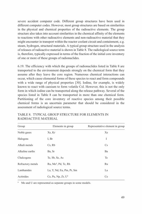
severe accident computer code. Different group structures have been used in different computer codes. However, most group structures are based on similarities in the physical and chemical properties of the radioactive elements. The group structure also takes into account similarities in the chemical affinity of the elements to reactions with other radioactive elements and non-radioactive material that they might encounter in transport within the reactor coolant circuit and containment, e.g. steam, hydrogen, structural materials. A typical group structure used in the analysis of releases of radioactive material is shown in Table 8. The radiological source term is, therefore, typically expressed in terms of the fraction of the initial core inventory of one or more of these groups of radionuclides.
6.19. The efficiency with which the groups of radionuclides listed in Table 8 are transported to the environment depends strongly on the chemical form that they assume after they leave the core region. Numerous chemical interactions can occur, which cause elemental forms of these species to react and form compounds with a wide range of physical properties [30]. Iodine, for example, is widely known to react with caesium to form volatile CsI. However, this is not the only form in which iodine can be transported along the release pathway. Several of the species listed in Table 8 can be transported in more than one chemical form. Partitioning of the core inventory of reactive species among their possible chemical forms is an uncertain parameter that should be considered in the assessment of radiological source terms.
TABLE 8. TYPICAL GROUP STRUCTURE FOR ELEMENTS IN RADIOACTIVE MATERIAL
Group Elements in group Representative element in group
Noble gases Xe, Kr Xe
Halogens I, Br I
Alkali metals Cs, Rb Cs
Alkaline earths Ba, Sr Ba
Chalcogens Te, Sb, Se, As Te
Refractory metals Ru, Moa, Pd, Tc, Rh Ru
Lanthanides La, Y, Nd, Eu, Pm, Pr, Sm La
Actinides Ce, Pu, Np, Zr, Ua Ce
a Mo and U are represented as separate groups in some models.
49

VERIFICATION AND VALIDATION OF COMPUTER CODES FOR SOURCE TERM ANALYSIS
6.20. Paragraphs 6.20 and 6.21 provide recommendations on meeting Requirement 18 of Ref. [2] on use of computer codes for Level 2 PSA. The integral code(s) used for the source term analysis should be verified and validated to provide confidence in the results that are produced. However, it needs to be recognized that the level to which verification and validation can be carried out for severe accident analysis codes is much less than for other codes used to support the PSA, such as the thermohydraulic codes used to support the success criteria for safety systems in the Level 1 PSA. This is because there is, in general, a limited applicability of experimental results to real reactor conditions, as it is not always possible to carry out experiments that reflect the extreme conditions that occur in a severe accident and the scale of the geometry of the reactor coolant system and the primary circuit.
6.21. The users of an integral code should be experienced in the use of the code and be familiar with the phenomena being modelled by the code and the way that they interact, the meaning of the input and output data, and the limitations of the code.
RESULTS OF THE SOURCE TERM ANALYSIS
6.22. The overall results of the source term analysis should be clearly presented and documented. The frequencies and characteristics of the source term categories should be clearly presented. One way of doing this is to present the results in the form of a matrix similar to the C matrix described in Section 5, in which the frequency (or the contribution to the total core damage frequency) of each release category is tabulated. An example format for this method of presenting the results of the source term analysis is shown in Table 9.
6.23. The source terms and frequencies of the release categories should be used to determine the large release frequency or the large early release frequency for comparison with numerical safety criteria where they have been set, as described in Section 8. (This will require the terms ‘large’ and ‘early’ to have been defined within the Level 2 PSA project. This can be done in a number of ways, as outlined in Section 8.)
50
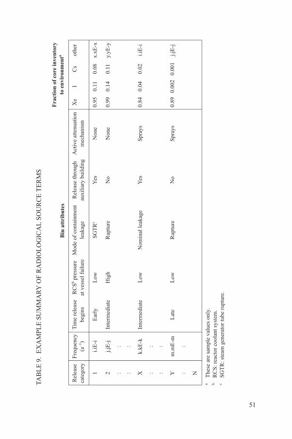
TAB
LE
9.
EX
AM
PL
E S
UM
MA
RY
OF
RA
DIO
LO
GIC
AL
SO
UR
CE
TE
RM
S
Bin
att
ribu
tes
Fra
ctio
n o
f co
re in
vent
ory
to e
nvi
ron
men
ta
Rel
ease
cate
gory
Freq
uenc
y(a
–1)
Tim
e re
leas
ebe
gins
RC
Sb pre
ssur
eat
ves
sel f
ailu
reM
ode
of c
onta
inm
ent
leak
age
Rel
ease
thro
ugh
auxi
liar
y bu
ildi
ngA
ctiv
e at
tenu
atio
nm
echa
nism
Xe
IC
sot
her
1i.i
E-i
Ear
lyL
owS
GT
Rc
Yes
Non
e0.
950.
110.
08x.
xE-x
2j.j
E-j
Inte
rmed
iate
Hig
hR
uptu
reN
oN
one
0.99
0.14
0.11
y.yE
-y
::
::
Xk.
kE-k
Inte
rmed
iate
Low
Nom
inal
leak
age
Yes
Spra
ys0.
840.
040.
02i.i
E-i
::
::
Ym
.mE
-mL
ate
Low
Rup
ture
No
Spra
ys0.
890.
002
0.00
1j.j
E-j
::
N
aT
hese
are
sam
ple
valu
es o
nly.
bR
CS
: rea
ctor
coo
lant
sys
tem
.c
SG
TR
: ste
am g
ener
ator
tube
rup
ture
.
51

6.24. An alternative format for displaying the results of the source term analysis is by means of a complementary cumulative distribution function that is based on the frequency of releases greater than X, where X varies from the smallest to the largest calculated quantity of release. (This will require the term ‘quantity of release’ to be defined within the Level 2 PSA project, which might be understood, for example, as the activity of a leading isotope or of a group of relevant isotopes.) The frequency of releases and the magnitude of releases should be considered together for the interpretation of the Level 2 PSA and its applications.
6.25. The insights gained from such a quantitative evaluation of radionuclide releases should be summarized and discussed. The results of the quantitative sensitivity analysis or uncertainty analysis should also be presented and discussed. In particular, for each radioactive material group, the frequency of exceeding a given release quantity should be provided. The results should clearly show the statistical significance of each complementary cumulative distribution function (mean, median, 95th percentile, etc.).
UNCERTAINTIES
6.26. Paragraphs 6.26–6.28 provide further recommendations on meeting Requirement 17 of Ref. [2] on uncertainty and sensitivity analysis for Level 2 PSA. In addition to the uncertainties in modelling severe accident phenomena, many of the chemical and physical processes governing the release of radioactive material from fuel, deposition and retention on reactor internal surfaces and from scrubbing by containment safety systems are still poorly understood. Major sources of uncertainty in the evaluation of source terms are listed in Table 10.
6.27. Past and ongoing research programmes have made significant progress towards reducing uncertainty in severe accident source terms (e.g. Ref. [32]). Uncertainties associated with the physical processes involved in core damage and core relocation lead to uncertainty in respect of the release of radioactive material from fuel. Uncertainties associated with containment response to beyond design basis accident conditions lead to uncertainty in respect of the driving forces for radioactive material transport along the pathway to the environment. Examples of uncertainties associated with these areas are given in Section 5.
6.28. These uncertainties are generally not taken into account explicitly in the probabilistic quantification of the Level 2 PSA. However, the uncertainties in the source term quantification should be addressed by carrying out sensitivity studies for the major sources of uncertainty that influence the results of the Level 2 PSA.
52

7. DOCUMENTATION OF THE ANALYSIS:PRESENTATION AND INTERPRETATION OF RESULTS
7.1. Details of the rationale and analyses employed for a Level 2 PSA should be reported in a way that presents information on the methods used, the PSA process, and the insights and conclusions drawn in a logical manner. The report should be compiled in such a way that it facilitates review activities, including peer review, and provides a structured entry route to detailed supporting material.
7.2. Comprehensive and general guidance on the requirements for, and the objectives, organization and preparation of, documentation for PSA are provided in Ref. [4]. This guidance is equally applicable to Level 2 PSA. This section provides specific recommendations on meeting Requirement 20 on documentation of safety assessment [2] for Level 2 PSA.
TABLE 10. ISSUES GIVING RISE TO UNCERTAINTIES IN SOURCE TERMS
∑ Uncertainties in core damage processes and containment behaviour (see Table 7)∑ Effects of fuel exposure (burnup) on the release rate of radioactive material from fuel∑ Chemical forms of volatile and semi-volatile species∑ Chemical interactions with fuel, neutron absorbers and structural materials during core
degradation ∑ Deposition rates of radioactive material and aerosols on the surfaces of the reactor coolant
circuit ∑ Deposition of radioactive material in piping and other components in accident sequences
with containment bypass ∑ Release of radioactive material and aerosols during molten core–concrete interaction ∑ Chemical processes during molten core–concrete interaction ∑ Interaction between hydrogen burn or radicals in flame fronts and airborne radioactive
material∑ Scrubbing efficiency of aerosols and vapours in suppression pools, ice beds or bubble
towers∑ Aqueous chemistry of radioactive material captured in water pools∑ Revaporization and resuspension of radioactive material from surfaces∑ Chemical decomposition of radioactive material aerosols
53

OBJECTIVES OF DOCUMENTATION
7.3. The documentation for a Level 2 PSA should provide sufficient information to satisfy the objectives of the study and to support the needs of the users of the Level 2 PSA. It should also facilitate its subsequent refinement, updating and maintenance in the light of changes to plant configuration or technical advances in severe accident analysis. Possible users of a Level 2 PSA include:
(a) Operating organizations of nuclear power plants (management and operating personnel);
(b) Designers and reactor vendors;(c) Reviewers;(d) Regulatory authorities and persons or organizations providing them with
technical support;(e) Other government bodies;(f) The public.
7.4. The documentation should be well structured, clear, concise and open to scrutiny by readers and reviewers, including peer reviewers. In addition, the Level 2 PSA documentation should be easily upgradeable for maintaining a living PSA concept, so as to meet Requirement 24 of Ref. [2] on maintenance of the safety assessment for Level 2 PSA and Requirement 12 of Ref. [2] on carrying out Level 2 PSA at all stages of the plant lifetime. Thus, it also needs to allow for easy broadening of the scope of the PSA in question and its use for additional applications. The underlying assumptions, exclusions, limitations and features are integral elements of the documentation for a Level 2 PSA and should be explicitly presented.
7.5. Conclusions should be distinct and should reflect not only the main general results, but should emphasize the conclusions drawn from the analysis of uncertainties associated with phenomena, models and databases and the contributory analyses. The effect of underlying assumptions, uncertainties and conservatisms in the analyses and methods on the results of the Level 2 PSA should be demonstrated through the presentation of the results of sensitivity studies.
7.6. If screening criteria have been applied to eliminate accident sequences with low frequencies of occurrence from further analysis, for example, from the output of the Level 1 PSA or in the definition of plant damage states, then an estimate of the contribution of the truncations should be assessed and should be presented with the final Level 2 PSA results.
54

7.7. The Level 2 PSA report should clearly document important findings of the Level 2 PSA, including:
(a) Plant specific design or operational vulnerabilities identified; (b) Key operator actions for mitigating severe accidents; (c) Potential benefits of various engineered safety systems; (d) Areas for possible improvement in operations or hardware for the plant and
the containment in particular.
7.8. At this stage, the results of the PSA may be compared with probabilistic safety criteria for Level 2 PSA, if these have been set. Available probabilistic safety criteria and/or goals vary considerably among Member States, but the most common forms for Level 2 PSA include criteria and/or goals for the frequency of a large early release and the maximum tolerable frequency of releases of various magnitudes. While the threshold for large early release frequency represents a point estimate frequency for a particular unacceptable release, the maximum tolerable frequency of releases of various magnitudes expands this concept across the full range of possible releases.
ORGANIZATION OF DOCUMENTATION
7.9. Some parts of the documentation may be intended for use within the operating organization, while other parts of the documentation may be intended for wider external use. Some of the users, for example the public, might use, primarily, the summary report of the PSA, while others might use the full PSA documentation, including the computer model. The nature and the amount of information for inclusion in the documentation for external use compared with that intended for in-house support documentation should be established by the PSA team and reviewed by the project management for the Level 2 PSA.
7.10. The Level 2 PSA documentation should contain all of the detailed information that would be needed to reconstruct the PSA study. To the extent possible, all of the intermediate analyses, rationales for probabilistic estimates and supporting calculations should be documented, either as appendices or as internal reports. All working papers and computer code inputs and outputs not included in the formal documentation for external use should be retained in a traceable format.
55

7.11. The recommendations on organization of documentation provided in the Safety Guide on Level 1 PSA [4] also apply to the case of Level 2 PSA. The Level 2 PSA documentation should be divided into three major parts, namely:
(1) Summary report;(2) Main report;(3) Appendices to the main report.
7.12. The summary report should be designed to provide an overview of motivations, objectives, scope, assumptions, results and conclusions of the PSA and potential impacts on plant design, operation and maintenance. The summary report generally is aimed at a wide audience of reactor safety specialists and should be adequate for high level review. Other aspects of the summary report are described in Ref. [4].
7.13. An outline of the main report should be also provided in the summary report, to guide reviewers to sections where additional details and supporting analyses are included. The summary report should be prepared by an individual who has an excellent overview of the entire PSA study. It should be prepared after the entire documentation has been completed and reviewed by individual task leaders and/or analysts for correctness and consistency.
7.14. The main report should give a clear and traceable presentation of the complete PSA study, including clear statements of all assumptions, rationales and plant specific aspects affecting the results.8
7.15. A sample outline for the documentation for a Level 2 PSA is provided in Annex III.
8. USE AND APPLICATIONS OF THE PSA
8.1. This section provides recommendations on meeting Requirement 23 of Ref. [2] on use of the safety assessment for Level 2 PSA. PSA has been applied in
8 The main report is intended for use by specialized PSA analysts and peer reviewers. The main report and all of the appendices should include sufficient information to support fully the conclusions of the Level 2 PSA.
56

the design and operation of nuclear power plants in many States to complement results obtained by traditional methods of safety assessment. Many PSA applications use the results of Level 1 PSA (Ref. [4]) and often also require Level 2 PSA results. The following list includes some successful examples of applications of Level 2 PSA; it should be noted that these applications of Level 2 PSA are not in use in every State:
(a) Comparison of results of the Level 2 PSA with probabilistic criteria to determine if the overall level of safety of the plant is adequate;
(b) Evaluation of plant design to identify potential vulnerabilities in the mitigation of severe accidents;
(c) Development of severe accident management guidelines that can be applied following core damage;
(d) Use of the source terms to provide an input into emergency planning;(e) Use of the source terms and frequencies to determine off-site consequences
(Level 3 PSA); (f) Prioritization of research relating to severe accident issues;(g) Use of a range of other PSA applications in combination with the
Level 1 PSA results.
SCOPE AND LEVEL OF DETAIL OF PSA FOR APPLICATIONS
8.2. The scope and the level of detail of the Level 2 PSA should be consistent with its intended uses or applications, examples of which are described below. For example, the scope and the level of detail of a PSA that was intended to provide an estimate of the large release frequency or the large early release frequency and be used to provide insights into the potential failure modes of the containment will be different from the scope of a Level 2 PSA that was intended to provide an input into emergency planning or to a Level 3 PSA. In the calculation of large release frequencies or large early release frequencies, there is a need to identify accident sequences and their frequencies where the release would be categorized as ‘large’. However, for the purposes of emergency planning or for a Level 3 PSA, the source terms and frequencies would need to be specified more accurately. In addition, the level of detail of the PSA would need to be greater if it were intended to use the Level 2 PSA model in a risk monitor.
8.3. To be suitable for a wide range of uses and applications, the Level 2 PSA should be based on a full scope Level 1 PSA as described in Ref. [4]. This requires that the Level 1 PSA: (a) includes a comprehensive set of internal initiating events, internal hazards, and natural and human made external hazards,
57

and (b) addresses all the modes of operation of the plant, including startup and operation at power, low power and all the modes that occur during plant shutdown and refuelling. This will ensure that the insights from the PSA relating to the risk significance of accident sequences, structures, systems and components, human errors, common cause failures, etc., are derived from a comprehensive, integrated model of the plant. If the Level 2 PSA is based on a Level 1 PSA that has a more limited scope or details, these limitations need to be taken into account in the application of the Level 2 PSA.
8.4. In order to meet Requirement 24 of Ref. [2] on maintenance of the safety assessment, the Level 2 PSA used for any application should be actively maintained and regularly updated, taking into account changes in plant design and operational practices as well as feedback from experience and advances in technology that may compromise the validity of the PSA. For the Level 2 PSA, this updating needs to take account of changes in the provisions made and the guidance provided for severe accident management, updates to the severe accident analysis carried out to support the Level 2 PSA model and the results of research carried out that provide a better understanding of the phenomena that occur during a severe accident.
USE OF THE PSA THROUGHOUT THE LIFETIME OF THE PLANT
8.5. The Level 2 PSA should be used to provide one of the inputs into design evaluation throughout the lifetime of a nuclear power plant. It should be used during the design process for a new plant to determine whether adequate features for the mitigation of severe accidents are being incorporated into the design of the plant and this should be updated throughout the construction and operational stages of the lifetime of the plant.
8.6. The Level 2 PSA should also be used to provide an input into the development of the severe accident management guidelines, which should be available when the plant goes into operation.
RISK INFORMED APPROACH
8.7. The aim of applying a risk informed approach is to ensure that a balanced approach is taken when making decisions on safety issues by considering probabilistic risk insights with any other relevant factors in an integrated manner [33].
58

8.8. In any of the applications of the Level 2 PSA described below, the insights from the PSA should be used as part of the process of risk informed decision making that takes account of all the relevant factors when making decisions on issues related to the prevention and mitigation of severe accidents at the plant:
(a) Any mandatory requirements that relate to the PSA application being addressed (which would typically include any legal requirements or regulations that need to be complied with);
(b) The insights from deterministic safety analysis; (c) Any other applicable insights or information (which could include a
cost–benefit analysis, remaining lifetime of the plant, inspection findings, operating experience, doses to workers that would arise in making necessary changes to the plant hardware, environmental protection concerns, etc.).
COMPARISON WITH PROBABILITIC SAFETY CRITERIA
8.9. The overall results of the Level 2 PSA should be compared with the probabilistic safety criteria (if these have been specified). The aim should be to determine whether the risk criteria or targets have been met or whether additional features for prevention or mitigation of accidents need to be provided.
8.10. This comparison should take account of the results of the sensitivity analyses that have been carried out and the uncertainties inherent in the Level 2 PSA. The sensitivity analyses and the uncertainty analyses should be used to indicate the degree of confidence in meeting the criterion or target and the likelihood that it may be exceeded.
8.11. A typical numerical safety criterion defined for the Level 2 PSA relates to the large release frequency or the large early release frequency. A large release means a release of radioactive material from the plant that would require off-site emergency arrangements to be implemented. The release can be specified in a number of ways including the following:
(a) As absolute quantities (in becquerels) of the most significant radionuclides released;
(b) As a fraction of the inventory of the core;(c) As a specified dose to the most exposed person off the site;(d) As a release resulting in ‘unacceptable consequences’.
59
8.12. In 1999, probabilistic criteria were proposed by the International Nuclear Safety Advisory Group (INSAG) [34] for a large off-site release of radioactive material requiring a short term off-site response. The following objectives were given.9 Several States have also set similar numerical values which have generally been defined as objectives or targets.
8.13. In addition, for future nuclear power plants, rather than defining probabilistic criteria, INSAG [34] has proposed that the objective should be “… the practical elimination of accident sequences that could lead to large early radioactive release, whereas severe accidents that could imply late containment failure would be considered in the design process with realistic assumptions and best estimate analysis so that their consequences would necessitate only protective measures limited in area and in time.”
USE OF PSA FOR DESIGN EVALUATION
8.14. The Level 2 PSA should be used to carry out a safety evaluation of the plant design. The aim should be to gain insights into how severe accidents progress, identify plant specific vulnerabilities and provide an input into the consideration of whether improvements need to be made to the design of the plant for the prevention or mitigation of severe accidents, such as the installation of hydrogen recombiners or filtered venting systems.
Identification of plant vulnerabilities
8.15. The use of Level 2 PSA for design evaluation is very similar to that for Level 1 PSA, as described in Ref. [4]. As well as calculating the overall value of the large release frequency or large early release frequency, the computer codes used to develop the Level 2 PSA model and to quantify it provide a range of other information including:
9 The objective for large off-site releases requiring short term off-site response is 1 ¥ 10–5 per reactor-year for existing plants. Reference [34] does not specify a numerical value for a large off-site radioactive release for future plants, but states the following qualitative objective: “Another objective for these future plants is the practical elimination of accident sequences that could lead to large early radioactive releases, whereas severe accidents that could imply late containment failure would be considered in the design process with realistic assumptions and best estimate analyses so that their consequences would necessitate only protective measures limited in area and in time.”
60
(a) The frequency of each of the release categories.(b) The possible combinations of failures (cutsets) that contribute to each of the
release categories.(c) The importance functions for systems, components and other basic events
included in the PSA model. (This will depend on the computer code used for the development of the Level 2 PSA but could include the Fussell-Vesely importance, the risk achievement worth, the risk reduction worth, the Birnbaum importance, etc.)
8.16. The information provided by the Level 2 PSA should be used to identify weaknesses in the features provided for the prevention and mitigation of severe accidents. This information could include:
(a) The significant failure modes of the primary circuit and the containment;(b) The dominant phenomena that lead to (early or late) containment failure; (c) The structures, systems and components that have the highest importance
for large release frequency or large early release frequency.
Consideration should be given to making improvements to the features provided for the prevention or mitigation of severe accidents in order to reduce those contributions to the overall risk that have the highest risk significance.
8.17. The improvements considered should include the provision of additional protective systems and features for mitigating the consequences of the severe accident. This could involve incorporating such additional protective systems and features into a new design or backfitting them into an existing plant.
8.18. The results of the Level 2 PSA should be used as a resource for determining whether adequate provisions for defence in depth have been made. For example, the PSA could provide a basis for determining whether severe accident management measures and guidelines fully address the fourth level of defence in depth as defined in Ref. [3].
Comparison of design options
8.19. When design improvements are being considered with regard to severe accident management measures, a range of options are often available. The Level 2 PSA may be used to provide an input into the comparison of these options.
61
8.20. The Level 2 PSA should be used to compare the benefits in terms of risk reduction from the incorporation of these additional systems and features. The way that this is done depends on the complexity of the modifications being considered, but could range from the production of a revised PSA model to post-processing the cutsets to take account of simpler changes and even to carrying out sensitivity studies that relate to the design options. In doing this, it needs to be recognized that a design change may impact a whole sequence of events modelled in the containment event tree, or even change the basis for evaluation of some nodes of the containment event tree. A design change might also affect the Level 1 PSA. Competing impacts need to be recognized and taken into account in the evaluation of the design change. As an example, a modification to the spray system may benefit the control of steam pressurization, but may have the potential to lead to combustible conditions in some time frames, or even lead to concerns about containment underpressure.
SEVERE ACCIDENT MANAGEMENT
8.21. The Level 2 PSA should be used as a basis for the evaluation of the measures in place and the actions that can be carried out to mitigate the effects of a severe accident after core damage has occurred. The aim of mitigatory measures and actions should be to arrest the progression of the severe accident or mitigate its consequences by preventing the accident from leading to failure of the reactor pressure vessel or the containment, and controlling the transport and release of radioactive material with the aim of minimizing off-site consequences. Examples of mitigatory actions that could be carried out for pressurized water reactors include:
(a) Opening the pressurizer relief valves in order to reduce the primary circuit pressure and so avoid molten core material being ejected from the reactor pressure vessel under high pressure;
(b) Adding water to the containment by any available means after the molten core has exited from the primary circuit so as to provide a cooling mechanism.
8.22. The results of the Level 2 PSA should be used to determine the effectiveness of the severe accident management measures that are described in the severe accident management guidelines or procedures, whether they have been specified using the Level 2 PSA or by any other method.
62

8.23. In developing a Level 2 PSA, it should be recognized that the phenomena that occur in the course of a severe accident are highly uncertain and often interrelated, so that an accident management measure that is aimed at mitigating a particular phenomenon might make another phenomenon more likely. Examples of this for pressurized water reactors include the following:
(a) Depressurization of the primary circuit may prevent high pressure melt ejection but might increase the probability of an in-vessel steam explosion.
(b) Introducing water into the containment may provide a cooling medium for molten core material after it has come out of the reactor pressure vessel but might increase the probability of an ex-vessel steam explosion.
(c) Operation of the containment sprays may provide a means of removing heat and radioactive material from the containment atmosphere but might increase the flammability of the containment atmosphere by condensing steam.
These interdependencies between the various phenomena that can occur during a severe accident should be identified using the Level 2 PSA and should be taken into account in the development of the severe accident management guidelines. Updates of the Level 2 PSA and updates of the severe accident management guidelines should be performed in an iterative manner to facilitate the progressive optimization of the severe accident management guidelines.
EMERGENCY PLANNING
8.24. The source terms and frequencies derived in the Level 2 PSA, along with calculations of the off-site dose as a function of distance, should be used as inputs into the development of off-site emergency planning. One or more reference accidents can be defined and used in this process.
8.25. An important requirement for a Level 2 PSA that is to be used for emergency planning is that the source terms should be accurately specified in terms of the quantities of radioactive material released and the additional attributes.
8.26. The source terms and frequencies derived in the Level 2 PSA can be used as an input to determine the extent of the emergency planning zones and the area for the distribution of prior information (so as to meet Requirement 23 of Ref. [2] on use of the safety assessment).
63
OFF-SITE CONSEQUENCES
8.27. The source terms and frequencies derived in the Level 2 PSA can be used as the starting point for determining the off-site consequences that can result from releases of radioactive material from the plant. Such off-site consequences include health effects to members of the public and a range of consequences, including contamination of land, water and food, evacuation, permanent relocation, etc.
8.28. The source terms and frequencies derived in the Level 2 PSA should be used as the starting point for the Level 3 PSA carried out to address the off-site consequences that could arise from a severe accident at the plant. The scope of the Level 2 PSA to be used for this purpose should include a detailed model of the transport of radioactive material and its release from the plant.
PRIORITIZATION OF RESEARCH
8.29. Level 2 PSA models the complicated and highly interrelated phenomena that occur after a severe accident. Although there has been a considerable amount of research into these phenomena, there is still a lack of knowledge in some areas that leads to a significant level of uncertainty in the predictions of the Level 2 PSA.
8.30. The Level 2 PSA should be used to provide a basis for the identification and prioritization of research activities. Such research activities should focus on the areas of uncertainty that have the highest risk significance.
OTHER PSA APPLICATIONS
8.31. The Level 2 PSA should be used in combination with the Level 1 PSA results for a number of applications, as described in Ref. [4] for the Level 1 PSA. The use of Level 1 and Level 2 PSAs in combination will provide additional insights to those obtained solely from the Level 1 PSA, since the relative importance of structures, systems and components is normally different for Level 2 PSA results, such as large release frequency or large early release frequency, than for Level 1 PSA results, such as core damage frequency.
64

REFERENCES
[1] EUROPEAN ATOMIC ENERGY COMMUNITY, FOOD AND AGRICULTURE ORGANIZATION OF THE UNITED NATIONS, INTERNATIONAL ATOMIC ENERGY AGENCY, INTERNATIONAL LABOUR ORGANIZATION, INTERNATIONAL MARITIME ORGANIZATION, OECD NUCLEAR ENERGY AGENCY, PAN AMERICAN HEALTH ORGANIZATION, UNITED NATIONS ENVIRONMENT PROGRAMME, WORLD HEALTH ORGANIZATION, Fundamental Safety Principles, IAEA Safety Standards Series No. SF-1, IAEA, Vienna (2006).
[2] INTERNATIONAL ATOMIC ENERGY AGENCY, Safety Assessment for Facilities and Activities, IAEA Safety Standards Series No. GSR Part 4, IAEA, Vienna (2009).
[3] INTERNATIONAL ATOMIC ENERGY AGENCY, Safety of Nuclear Power Plants: Design, IAEA Safety Standards Series No. NS-R-1, IAEA, Vienna (2000).
[4] INTERNATIONAL ATOMIC ENERGY AGENCY, Development and Application of Level 1 Probabilistic Safety Assessment for Nuclear Power Plants, IAEA Safety Standards Series No. SSG-3, IAEA, Vienna (2010).
[5] INTERNATIONAL ATOMIC ENERGY AGENCY, Convention on Nuclear Safety, Legal Series No. 16, IAEA, Vienna (1994).
[6] INTERNATIONAL ATOMIC ENERGY AGENCY, The Management System for Facilities and Activities, IAEA Safety Standards Series No. GS-R-3, IAEA, Vienna (2006).
[7] KHATIB-RAHBAR, M., et al., A probabilistic approach to quantifying uncertainties in the progression of severe accidents, Nucl. Sci. Eng. 102 (1989) 219.
[8] BUDNITZ, R.J., et al., Recommendations for Probabilistic Seismic Hazard Analysis: Guidance on Uncertainty and Use of Experts, Rep. NUREG/CR-6372, Lawrence Livermore Natl Lab., CA (1997).
[9] MEYER, M.A., BOOKER, J.M., Eliciting and analyzing expert judgment: A practical guide, Rep. NUREG/CR-5424, Los Alamos Natl Lab., NM (1990).
[10] OECD NUCLEAR ENERGY AGENCY, Evaluation of Uncertainties in Relation to Severe Accidents and Level-2 Probabilistic Safety Analysis, Rep. NEA/CSNI/R(2007)2, OECD, Paris (2007).
[11] THEOFANOUS, T., YAN, H., “ROAAM: A risk-oriented accident analysis methodology”, Probabilistic Safety Assessment and Management (Proc. Int. Conf. Beverly Hills, 1991), Elsevier Science, New York (1991) 1179.
[12] HARPER, F.T., et al., Evaluation of Severe Accident Risks: Quantification of Major Input Parameters, Rep. NUREG/CR-4551, Vol. 2, Part 4, Sandia Natl Labs, NM (1991).
[13] MENDOZA, Z.T., FREEMAN, M., LEONARD, M., EUTO, J., HALL, J., Generic Framework for IPE Back-End (Level 2) Analysis, Rep. NSAC-159, Electric Power Research Institute, Palo Alto, CA (1991).
[14] NUCLEAR REGULATORY COMMISSION, Severe Accident Risks: An Assessment for Five U.S. Nuclear Power Plants, Rep. NUREG-1150, US Govt Printing Office, Washington, DC (1990).
[15] SEHGAL, B.R., Accomplishments and challenges of the severe accident research, Nucl. Eng. Des. 210 (2001) 79.
65

[16] OECD NUCLEAR ENERGY AGENCY, Level 2 PSA Methodology and Severe Accident Management: 1997, Rep. NEA/CSNI/R(97)11, OECD, Paris (1997).
[17] PILCH, M.M., YAN, H., THEOFANOUS, T.G., The Probability of Containment Failure by Direct Containment Heating in Zion, Rep. NUREG/CR-6075, Suppl. 1, Sandia Natl Labs, NM (1994).
[18] REMPE, J.L., et al., Light Water Reactor Lower Head Failure Analysis, Rep. NUREG/CR-5642, Idaho Natl Eng. Lab., ID (1993).
[19] CHU, T.Y., et al., Lower Head Failure Experiments and Analyses, Rep. NUREG/CR-5582, Sandia Natl Labs, NM (1998).
[20] BREITUNG, W., et al., Flame Acceleration and Deflagration-to-Detonation Transition in Nuclear Safety, State-of-the-Art Report by a Group of Experts, Rep. NEA/CSNI/R(2000)7, OECD, Paris (2000).
[21] GAUNTT, R.O., “An uncertainty analysis for hydrogen generation in station blackout accidents using MELCOR 1.8.5”, paper presented at NURETH-11, Int. Top. Mtg on Nuclear Reactor Thermal Hydraulics, Avignon, 2005.
[22] HELTON, J.C., Uncertainty and sensitivity analysis techniques for use in performance assessment for radioactive waste disposal, Reliab. Eng. Syst. Saf. 42 (1993) 327–367.
[23] HAMBY, D.M., A review of techniques for parameter sensitivity analysis of environmental models, Environ. Monit. Assess. 32 (1994) 135–154.
[24] McKAY, M., MEYER, M., Critique of and limitations on the use of expert judgments in accident consequence uncertainty analysis, Radiat. Prot. Dosim. 90 (2000) 325–330.
[25] CLEMENT, B., et al., LWR severe accident simulation: synthesis of the results and interpretation of the first Phebus FP experiment FPT0, Nucl. Eng. Des. 226 (2003) 5–82.
[26] MAAP 4.04 User Guidance, EPRI, May 1994.[27] GAUNTT, R.O., et al., MELCOR Computer Code Manuals: Version 1.8.5,
Rep. NUREG/CR-6119, Vol. 3, Sandia Natl Labs, NM (2001).[28] ANG, M.L., et al., A risk-based evaluation of the impact of key uncertainties on the
prediction of severe accident source terms — STU, Nucl. Eng. Des. 209 (2001) 183.[29] AMERICAN SOCIETY OF MECHANICAL ENGINEERS, Standard for Probabilistic
Risk Assessment for Nuclear Power Plant Applications: An American National Standard, Rep. ASME RA-Sa-2003, ASME, New York (2003).
[30] INTERNATIONAL ATOMIC ENERGY AGENCY, A Simplified Approach to Estimating Reference Source Terms for LWR Designs, IAEA-TECDOC-1127, IAEA, Vienna (1999).
[31] CLÉMENT, B., Towards Reducing the Uncertainties on Source Term Evaluations: an IRSN/CEA/EDF R&D Programme, (2004), http://www.eurosafe-forum.org
[32] OECD NUCLEAR ENERGY AGENCY, Insights into the Control of the Release of Iodine, Cesium, Strontium and Other Fission Products in the Containment by Severe Accident Management, Rep. NEA/CSNI/R(2000)9, OECD, Paris (2000).
[33] INTERNATIONAL ATOMIC ENERGY AGENCY, Applications of Probabilistic Safety Assessment (PSA) for Nuclear Power Plants, IAEA-TECDOC-1200, IAEA, Vienna (2001).
[34] INTERNATIONAL NUCLEAR SAFETY ADVISORY GROUP, Basic Safety Principles for Nuclear Power Plants 75-INSAG-3 Rev. 1, INSAG-12, IAEA, Vienna (1999).
66

Annex I
EXAMPLE OF A TYPICAL SCHEDULE FOR A LEVEL 2 PSA
I–1. Table I–1 shows a simplified schedule for a short Level 2 PSA based on the tasks described in this Safety Guide. The periods shown are representative of the minimum expected duration of the task for a typical PSA scope and for typical analysis methods and composition of analysis teams. Particular design aspects, degree of knowledge of applicable severe accident phenomena, availability of suitable reference plant analyses, etc., may considerably affect the duration of the various tasks. In addition, some tasks are of an iterative nature. Tasks may need to be split into more than one phase so that some of them can be repeated when the results of other tasks are available. This is not shown in the table, which is only intended to provide some orientation.
TABLE I-1. EXAMPLE SCHEDULE FOR A LEVEL 2 PSA
1 2 3 4 1 2 3 4 5 6 7 8 9 10 11 12
Management and organization 1. Definition of objectives 2. Definition of scope 3. Project management plan
4. Selection of approach and establishment of procedures
5. Team organization 6. Team training 7. Funding and scheduling
8. Setting of quality assurance procedures 9. Selection of internal peer reviewers
Study performance 10. Plant familiarization, identification of important design features
11. Interface to Level 1 PSA and sequence grouping
12. Accident progression and containment analyses:
a. Containment performance analysis b. Severe accident progression analysis c. Development and quantification of containment event trees
d. Treatment of accident progression uncertainties
e. Summary and interpretation of accident progression results
13. Source terms for severe accidents: a. Binning of containment event trees end states into release categories
b. Source terms analysis
c. Treatment of uncertainties in source terms
d. Summary and interpretation of results Documentation of PSA: Display and interpretation of results
14. Integration, interpretation and documentation of results:
a. Objectives and principles of documentation
b. Organization of documentation c. Preparation of documentation
Quality control and review
Month
Planning Study performance
67
Annex II
COMPUTER CODES FOR SIMULATION OF SEVERE ACCIDENTS
INTRODUCTION
II–1. Severe accident phenomena are complex and have many interdependencies which can be realistically examined using complex computer codes. This annex provides insights into the type of code typically used in Level 2 PSAs and a brief description of their areas of application.
GENERAL DESCRIPTION OF COMPUTER CODES
Types of code
II–2. The codes that model the physical response of the core, the reactor coolant system and the containment to severe accidents can be divided into three types according to their capabilities and intended use:
(1) Mechanistic codes calculate governing phenomena with models based on first principles, with computational resources being of secondary importance. Mechanistic codes are used typically in research to design and analyse severe accident experiments. Once validated against appropriate experimental conditions, they are also used to establish benchmarks for simpler codes. Codes of this type span a wide range of technical disciplines, from the behaviour of damaged fuel to the release of radioactive material, and from transport to hydrogen mixing and combustion processes. Examples of codes in each of these areas are given in para. II–9.
(2) Integral codes, which are designed for routine application in PSA, generally use simplified models of some phenomena so that calculations can be completed relatively quickly (within hours or at most a few days with the current computing technology). As they are relatively fast running, these codes can be used to evaluate plant response to many different accident sequences, or can be run several times for the same accident sequence to support uncertainty analysis. To ensure that the overall execution time of the code is reasonable, the modelling approach to some phenomena is simpler than the approaches used in mechanistic codes. The processes governing fuel damage and melting are offered as an example of the sort of simplification used. In a mechanistic code, models might be used
68

to evaluate explicitly the individual effects of several damage mechanisms within fuel rods, including swelling of fuel pellets and ‘foaming’ due to the expansion of fission product gases, thermomechanical interactions between the swollen fuel pellet and bounding clad, local ballooning at weak points in the clad, changes in material composition and properties associated with formation of eutectic mixtures, material liquefaction and candling, etc. This same process might be treated in a simpler and composite manner in integral codes. For example, clad ‘failure’ (i.e. release of the gap inventory of radionuclides) might be represented by specifying an effective clad failure temperature, while the effect of eutectic formation on liquefaction properties of the fuel might simply be represented by reducing the effective ‘melting temperature’ of the fuel. The extent to which such simplifications properly reflect important characteristics of the actual governing phenomena is determined by comparison of the calculated results with experimental data and with the results of parallel calculations performed with mechanistic codes. Examples of such comparisons are found in Refs [II–1] and [II–2].
(3) Parametric codes and algorithms provide rough estimates of parameters for specific PSA applications, such as estimation of the radiological source term [II–3] or of containment loads accompanying high pressure melt ejection [II–4]. Such tools are generally used to establish the primary technical basis when more runs are needed than can be reasonably handled, even by contemporary PSA codes. Parametric codes are based on simple parametric models that interpolate between fixed points, for which calculations with a more complicated code have already been performed, to determine the values of the parameters. The use of such codes is reasonable for the generation of uncertainty values, but it is important to take into account that the parameters used in the codes, as well as the results produced by them, have to be calibrated by more detailed calculations or experimental data.
II–3. In the past, an approach was used where separate codes, each dealing with a particular phase or aspect of severe accident behaviour, were coupled in a suite, with some interfacing facility for the transfer of information between the codes. However, for routine PSA application, it is desirable to have automatic transfer of information between the elements of a code suite as manual transfer is slow and can also lead to the introduction of errors. A more integrated and modular approach has tended to be adopted in the newer generation of severe accident codes.
69

Validation status of a code
II–4. Verification and validation of computer codes are crucial mechanisms that enhance confidence in their application. Achieving a state with severe accident codes that could reasonably be termed validation is very difficult. However, the extreme conditions that occur in a severe accident and the scale of the physical geometry are difficult to realize in experiments. The process of validation, in general, comprises a validation matrix involving many simulations. Care needs to be taken with code validations that have been achieved by varying the values of user supplied parameters until a reasonable fit to experimental data is achieved. At best, this is an indirect experimental measurement of the parameter values and not an independent validation of the code.
Use of the codes
II–5. Deterministic accident analysis codes need to be designed so that a Level 2 PSA analyst having a good degree of familiarity with general accident phenomena can run them reliably without needing to have the same detailed knowledge as a specialist using a mechanistic code dealing with a particular phenomenon or a phase of a severe accident. However, it is essential that the analyst has a good working knowledge of the reactor systems. In order for the code calculations to be meaningfully incorporated into the framework of a Level 2 PSA, the analyst will need to have a reasonable knowledge of the following:
(a) The phenomena addressed in a code and their modelling approach and limitations;
(b) The meaning of the input variables;(c) The meaning of the output variables.
II–6. The point to be emphasized is that, given the complexity of these issues, the code cannot simply be treated as a ‘black box’. The user will need to have a sound knowledge of the strengths and limitations of the code, which may not be used out of the range of situations and conditions for which it has been designed.
EXAMPLES OF INTEGRAL CODES FOR SEVERE ACCIDENT ANALYSIS
II–7. This section provides a brief description of some specific codes currently in use for Level 2 PSAs, which deal with most or all of the phenomena shown in Fig. II–1. A list of major mechanistic codes is also included.
70
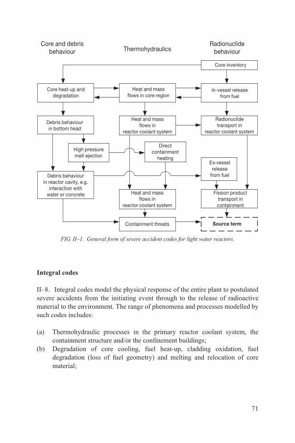
Integral codes
II–8. Integral codes model the physical response of the entire plant to postulated severe accidents from the initiating event through to the release of radioactive material to the environment. The range of phenomena and processes modelled by such codes includes:
(a) Thermohydraulic processes in the primary reactor coolant system, the containment structure and/or the confinement buildings;
(b) Degradation of core cooling, fuel heat-up, cladding oxidation, fuel degradation (loss of fuel geometry) and melting and relocation of core material;
Core inventory
Containment threats Source term
Core and debrisbehaviour Thermohydraulics
Radionuclidebehaviour
Core heat-up anddegradation
Heat and massflows in core region
In-vessel releasefrom fuel
Debris behaviourin bottom head
Heat and massflows in
reactor coolant system
Radionuclidetransport in
reactor coolant system
High pressuremelt ejection
Directcontainment
heatingEx-vesselrelease
from fuelDebris behaviourin reactor cavity, e.g.
interaction withwater or concrete Heat and mass
flows inreactor coolant system
Fission producttransport incontainment
FIG. II–1. General form of severe accident codes for light water reactors.
71
(c) Heat-up of the reactor pressure vessel lower head from relocated fuel material and the thermal and mechanical loading and failure of the reactor pressure vessel lower head;
(d) Transfer of core material from the reactor pressure vessel to the containment ‘cavity’;
(e) Thermochemical interactions between molten core debris and concrete on the containment floor and resulting generation of aerosols;
(f) In-vessel and ex-vessel hydrogen production, transport and combustion;(g) Radioactive material release (aerosol and vapour), transport and deposition;(h) Behaviour of radioactive aerosols in the reactor containment building,
including scrubbing in water pools, and aerosol mechanics in the containment atmosphere, such as particle agglomeration and gravitational settling;
(i) Impact of engineered safety features on thermohydraulic and radionuclide behaviour.
Major codes of this type are summarized in Table II–1.
Mechanistic codes
II–9. Examples of mechanistic codes that have been used in recent severe accident studies are listed in Tables II–2 and II–3. The phenomena addressed are indicated in the tables. The level of detail examined by these codes generally exceeds that necessary for most Level 2 PSAs. Nevertheless, their application is occasionally required under special circumstances, such as when particular issues are unusually important to severe accident behaviour in a unique plant design.
72
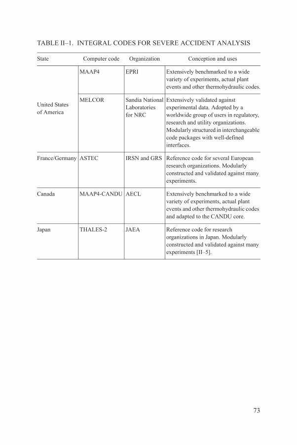
TABLE II–1. INTEGRAL CODES FOR SEVERE ACCIDENT ANALYSIS
State Computer code Organization Conception and uses
United Statesof America
MAAP4 EPRI Extensively benchmarked to a wide variety of experiments, actual plant events and other thermohydraulic codes.
MELCOR Sandia NationalLaboratoriesfor NRC
Extensively validated against experimental data. Adopted by a worldwide group of users in regulatory, research and utility organizations.Modularly structured in interchangeable code packages with well-defined interfaces.
France/Germany ASTEC IRSN and GRS Reference code for several European research organizations. Modularly constructed and validated against many experiments.
Canada MAAP4-CANDU AECL Extensively benchmarked to a wide variety of experiments, actual plant events and other thermohydraulic codes and adapted to the CANDU core.
Japan THALES-2 JAEA Reference code for research organizations in Japan. Modularly constructed and validated against many experiments [II–5].
73
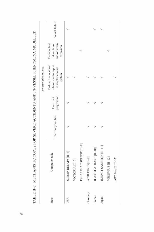
TAB
LE
II–
2. M
EC
HA
NIS
TIC
CO
DE
S F
OR
SE
VE
RE
AC
CID
EN
TS
AN
D I
N-V
ESS
EL
PH
EN
OM
EN
A M
OD
EL
LE
D
Stat
eC
ompu
ter
code
In-v
esse
l phe
nom
ena
The
rmoh
ydra
ulic
sC
ore
mel
tpr
ogre
ssio
n
Rad
ioac
tive
mat
eria
lre
leas
e an
d tr
ansp
ort
in r
eact
or c
oola
ntsy
stem
Fue
l–co
olan
tin
tera
ctio
nsan
d/or
ste
amex
plos
ion
Ves
sel f
ailu
re
USA
SCD
AP
-RE
LA
P5 [
II–6
]√
√√
√
VIC
TO
RIA
[II
–7]
√
PM-A
LPH
A/E
SPR
OS
E [
II–8
]√
Ger
man
yA
TH
LE
T-C
D [
II–9
]√
√√
Fran
ceIC
AR
E/C
AT
HA
RE
[II
–10]
√√
√√
Japa
nIM
PAC
T-SA
MP
SON
[II
–11]
√√
√√
VE
SU
VIU
S [
II–1
2]√
AR
T M
od.2
[II
–13]
√
74

TAB
LE
II–
3. M
EC
HA
NIS
TIC
CO
DE
S F
OR
SE
VE
RE
AC
CID
EN
TS
AN
D E
X-V
ES
SEL
PH
EN
OM
EN
A M
OD
EL
LE
D
Stat
eC
ompu
ter
code
Ex-
vess
el p
heno
men
a
Hig
h pr
essu
rem
elt e
ject
ion
Cor
e–co
ncre
tein
tera
ctio
n
Rad
ioac
tive
mat
eria
l rel
ease
from
deb
ris
Rad
ioac
tive
mat
eria
l tra
nspo
rtin
con
tain
men
t
Hyd
roge
nm
ixin
gH
ydro
gen
com
bust
ion
USA
CO
NTA
IN [
II–1
4]√
√√
√a
√
Ger
man
yC
OC
OS
YS
[II
–15]
√√
√√
√
USA
/Ger
man
yG
AS
FL
OW
[II
–16]
√√
Japa
nA
RT
Mod
.2 [
II–1
3]√
aA
sim
plif
ied
trea
tmen
t rel
ativ
e to
tool
s ba
sed
on c
ompu
tatio
nal f
luid
dyn
amic
s, su
ch a
s th
ose
in G
AS
FLO
W.
75
PROBABILISTIC CODES
II–10. Codes for simulation of fault trees and event trees and other simulation codes typically used for Level 1 PSAs are also used for Level 2 PSAs. In many cases, such codes have been adapted or enhanced to address certain unique requirements of Level 2 PSA applications, such as the solution of logic models with large event probabilities, and enhanced capabilities or more diverse methods for addressing uncertainties. A compilation of computer codes for Level 1 PSA is provided in Ref. [II–4]. Codes that have been specifically developed for containment event tree analysis are generally very well qualified for phenomenological issues in Level 2 PSA, but may have to be adapted to model the behaviour of systems.
REFERENCES TO ANNEX II
[II–1] JONES, A.V., et al., Validation of severe accident codes against Phebus FP for plant applications: Status of the PHEBEN2 project, Nucl. Eng. Des. 221 (2003) 225–240.
[II–2] ADROGUER, B., et al., Core Loss During a Severe Accident (COLOSS Project) Final Synthesis Report, Rep. IRSN/DPAM/Dir/04-0008, SAM-COLOSS-P078, Nucl. Eng. Des. 221 (2003) S55–76.
[II–3] INTERNATIONAL ATOMIC ENERGY AGENCY, A Simplified Approach to Estimating Reference Source Terms for LWR Designs, IAEA-TECDOC-1127, IAEA, Vienna (1999).
[II–4] LEONARD, M.T., Rough estimates of severe accident containment loads accompanying vessel breach in BWRs, Nucl. Technol. 108 (1994) 320–337.
[II–5] KAJIMOTO, M., MURAMATSU, K., WATANABE, N., “Development of THALES-2, a computer code for coupled thermal-hydraulics and fission product transport analysis for severe accident at LWRs and its application to analysis of fission product revaporization phenomena”, Safety of Thermal Reactors (Proc. ANS Int. Top. Mtg, Portland, 1991), American Nuclear Society, La Grange Park, IL (1991) 584.
[II–6] IDAHO NATIONAL ENGINEERING AND ENVIRONMENTAL LABORATORY, SCDAP/RELAP5-3D Code Manual, Rep. INEEL/EXT-02-00589, 5 Vols, Rev. 2.2, INEEL, ID (2003).
[II–7] HEAMES, T.J., et al., VICTORIA: A Mechanistic Model of Radionuclide Behavior in the Reactor Coolant System Under Severe Accident Conditions, Rep. NUREG/CR-5545, Rep. SAND90-0756, Rev. 1, Sandia Natl Labs, US Govt Printing Office, Washington, DC (1992).
[II–8] YUEN, W.W., et al., The verification basis of the PM-ALPHA [and ESPROSE.m] code, Nucl. Eng. Des. 189 (1999) 59–138.
[II–9] TRAMBAUER, K., et al., ATHLET-CD User’s Manual, GRS-P-4, Gesellschaft für Anlagen- und Reaktorsicherheit mbH (GRS), Cologne (2004).
76

[II–10] BERTRAND, F., SEILER, N., “Analysis of QUENCH tests including a B4C control rod with ICARE/CATHARE and B4C oxidation modelling assessment”, paper presented at NURETH-11, Int. Top. Mtg on Nuclear Reactor Thermal Hydraulics, Avignon, 2005.
[II–11] NAKADAI, Y., et al., “Integral severe accident analysis of light water nuclear power plants by IMPACT-SAMPSON code”, paper presented at NURETH-10, Int. Top. Mtg on Nuclear Reactor Thermal Hydraulics, Seoul, 2003.
[II–12] VIEROW, K., Development of the VESUVIUS code for steam explosion analysis, Jap. J. Multiphase Flow 12 (3) (1998) 242–248, 358–364.
[II–13] KAJIMOTO, M., MURAMATSU, K., “The Validation of the ART Code through Comparison with NSPP Experiments in the Steam-Air Environment,” Aerosol Behavior and Thermal-Hydraulics in the Containment (Proc. OECD/NEA Workshop Fontenay-aux-Roses, 1990), OECD, Paris (1990) 145.
[II–14] MURATA, K.K., et al., Code Manual for CONTAIN 2.0: A Computer Code for Nuclear Reactor Containment Analysis, Rep. NUREG/CR-6533, Rep. SAND97-1735, Sandia Natl Labs, NM (1997).
[II–15] ALLELEIN, H.J., et al., Entwicklung und Verifikation eines Containment-Codesystems (COCOSYS) und eines deutsch-französischen Integralcodes (ASTEC), GRS-A-2736, GRS-A-2737, Gesellschaft für Anlagen- und Reaktorsicherheit mbH (GRS), Cologne (1999).
[II–16] ROYL, P., et al., “Status of development, validation, and application of the 3D CFD code GASFLOW at FZK”, Use of Computational Fluid Dynamics Codes for Safety Analysis of Nuclear Reactor Systems, IAEA-TECDOC-1379, IAEA, Vienna (2003).
77
Annex III
SAMPLE OUTLINE OF DOCUMENTATIONFOR A LEVEL 2 PSA STUDY
S. Summary report
S1. IntroductionS2. Overview of the objectives and motivation for the studyS3. Overview of the approachS4. Results of containment failure modes and likelihoodsS5. Radiological source terms and their frequencies (complementary cumulative
distribution functions)S6. Summary of plant vulnerabilities to severe accidents, interpretation of results S7. Conclusions and recommendationsS8. Possible risk reduction measuresS9. Organization of the main report
M. Main report
M1. IntroductionM1.1 BackgroundM1.2 ObjectivesM1.3 Scope of the studyM1.4 Project organization and managementM1.5 Composition of the study teamM1.6 Overview of the approachM1.7 Structure of the report
M2. Description of the design of the plant and the containmentM2.1 Plant and containment design features affecting severe accidentsM2.2 Operational characteristicsM2.3 Description of plant modifications and containment system modifications
(if any)
M3. Interface to Level 1 PSAM3.1 Grouping of accident sequences and specification of attributesM3.2 Plant damage states for internal initiating events and associated
uncertaintiesM3.3 Plant damage states for external initiating events and associated
uncertaintiesM3.4 Plant damage states for other power states and associated uncertainties
78
M4. Analysis of the containment’s structural performanceM4.1 Description of the structural design and failure modes of the containmentM4.2 Approach for structural analysisM4.3 Structural response and fragility resultsM4.4 Summary of uncertainties and/or fragility curves for containment
performanceM4.5 Impact of external events
M5. Accident progression and containment analysisM5.1 Severe accident progression analysis
M5.1.1 Scope of analysisM5.1.2 Method of analysis (codes, models, etc.)M5.1.3 Summary of point estimate results for plant damage states
analysedM5.2 Accident progression event trees/containment event trees
M5.2.1 Containment event tree structureM5.2.2 Operating procedures and recoveryM5.2.3 Containment event tree quantification processM5.2.4 Binning of containment event tree end statesM5.2.5 Treatment of uncertaintiesM5.2.6 Results
M5.2.6.1 Point estimate C matrixM5.2.6.2 Uncertainties in failure probabilitiesM5.2.6.3 Interpretation of results
M6. Accident source termsM6.1 Grouping of radioactive materialsM6.2 Method of analysis (codes, models, etc.)M6.3 Summary of point estimate results for plant damage states analysedM6.4 Treatment of uncertaintiesM6.5 Results
M6.5.1 Point estimate source term characteristicsM6.5.2 Uncertainties in source term characteristicsM6.5.3 Interpretation of results
M7. Sensitivity and importance analysesM7.1 Identification of sensitivity issuesM7.2 Results of sensitivity analysisM7.3 Importance ranking of issues, systems and components
M8. ConclusionsM8.1 Key insights on characteristics of severe accidents and containment responseM8.2 Design features and inherent mitigation benefitsM8.3 Conclusions relative to PSA objectives
79
A. Appendices
A1. Basis for containment structural fragilitiesA2. Basis for containment event tree quantificationA3. Results of deterministic severe accident analyses
A3.1 Containment loadsA3.2 Accident source terms
A4. Basis for probability distribution and ranges of uncertain parametersA5. Detailed results of uncertainty analysis and/or sensitivity analysis
80

CONTRIBUTORS TO DRAFTING AND REVIEW
Alzbutas, R. Lithuanian Energy Institute, Lithuania
Ang, M. E-ON, United Kingdom
Bagdonas, A. Ignalina Nuclear Power Plant, Lithuania
Boneham, P. Jacobsen Engineering, United Kingdom
Bryant, R. Rolls-Royce, United Kingdom
Burgazzi, L. ENEA, Italy
Bykov, M. OKB “Gidropress”, Russian Federation
El-Shanawany, M. International Atomic Energy Agency
Elter, J. Paks Nuclear Power Plant, Hungary
Goertz, R. Bundesamt für Strahlenschutz, Germany
Hari, V. Nuclear Power Corporation of India, India
Hessel, P. Canadian Nuclear Safety Commission, Canada
Hustak, S. Nuclear Research Institute Rez, Czech Republic
Kajimoto, M. Japan Nuclear Energy Safety Organization, Japan
Kivirinta, T. Fortum Power and Heat Oy, Finland
Kompella, D. Reltech Consulting, India
Kouzmina, I. International Atomic Energy Agency
Kovacs, Z. Relko Ltd., Slovakia
Leonard, M. Dycoda LLC, United States of America
Loeffler, H. GRS, Germany
81

Lopez, A. Comisión Nacional de Seguridad Nuclear ySalvaguardias, Mexico
Lyubarskiy, A. International Atomic Energy Agency
Palmaerts, S. Tractebel Engineering, Belgium
Parry, G. Nuclear Regulatory Commission,United States of America
Rogers, P. Rolls-Royce, United Kingdom
Shepherd, C. Corporate Risk Associates, United Kingdom
Sorel, V. EDF/DPI/DIN/SEPTEN, France
Taglioni, A. ENEA, Italy
Yang, Zhichao China Nuclear Power Technology Research Institute, China
Yllera, J. International Atomic Energy Agency
Youngchuay, U. Thailand Institute of Nuclear Technology, Thailand
Zeng, Yi Canadian Nuclear Safety Commission, Canada
Zhao, Bo Beijing Institute of Nuclear Engineering, China
82

BODIES FOR THE ENDORSEMENTOF IAEA SAFETY STANDARDS
An asterisk denotes a corresponding member. Corresponding members receive drafts for comment and other documentation but they do not generally participate in meetings. Two asterisks denote an alternate.
Commission on Safety Standards
Argentina: González, A.J.; Australia: Loy, J.; Belgium: Samain, J.-P.; Brazil:Vinhas, L.A.; Canada: Jammal, R.; China: Liu Hua; Egypt: Barakat, M.; Finland: Laaksonen, J.; France: Lacoste, A.-C. (Chairperson); Germany: Majer, D.; India: Sharma, S.K.; Israel: Levanon, I.; Japan: Fukushima, A.; Korea, Republic of: Choul-Ho Yun; Lithuania: Maksimovas, G.; Pakistan: Rahman, M.S.; Russian Federation: Adamchik, S.; South Africa: Magugumela, M.T.; Spain: Barceló Vernet, J.; Sweden: Larsson, C.M.; Ukraine: Mykolaichuk, O.; United Kingdom: Weightman, M.; United States of America: Virgilio, M.; Vietnam: Le-chi Dung; IAEA: Delattre, D. (Coordinator); Advisory Group on Nuclear Security: Hashmi, J.A.; European Commission: Faross, P.; International Nuclear Safety Group: Meserve, R.; International Commission on Radiological Protection: Holm, L.-E.; OECD Nuclear Energy Agency: Yoshimura, U.; Safety Standards Committee Chairpersons: Brach, E.W. (TRANSSC); Magnusson, S. (RASSC); Pather, T. (WASSC); Vaughan, G.J. (NUSSC).
Nuclear Safety Standards Committee
Algeria: Merrouche, D.; Argentina: Waldman, R.; Australia: Le Cann, G.; Austria: Sholly, S.; Belgium: De Boeck, B.; Brazil: Gromann, A.; *Bulgaria: Gledachev, Y.; Canada: Rzentkowski, G.; China: Jingxi Li; Croatia: Valčić, I.; *Cyprus: Demetriades, P.; Czech Republic: Šváb, M.; Egypt: Ibrahim, M.; Finland: Järvinen, M.-L.; France: Feron, F.; Germany: Wassilew, C.; Ghana: Emi-Reynolds, G.; *Greece: Camarinopoulos, L.; Hungary: Adorján, F.; India: Vaze, K.; Indonesia: Antariksawan, A.; Iran, Islamic Republic of: Asgharizadeh, F.; Israel: Hirshfeld, H.; Italy: Bava, G.; Japan: Kanda, T.; Korea, Republic of: Hyun-Koon Kim; Libyan Arab Jamahiriya: Abuzid, O.; Lithuania: Demčenko, M.; Malaysia: Azlina Mohammed Jais; Mexico: Carrera, A.; Morocco: Soufi, I.; Netherlands: van der Wiel, L.; Pakistan: Habib, M.A.; Poland: Jurkowski, M.; Romania: Biro, L.; Russian Federation: Baranaev, Y.; Slovakia: Uhrik, P.; Slovenia: Vojnovič, D.; South Africa: Leotwane, W.; Spain: Zarzuela, J.; Sweden: Hallman, A.; Switzerland: Flury, P.; Tunisia: Baccouche, S.;
83

Turkey: Bezdegumeli, U.; Ukraine: Shumkova, N.; United Kingdom: Vaughan, G.J. (Chairperson); United States of America: Mayfield, M.; Uruguay: Nader, A.; European Commission: Vigne, S.; FORATOM: Fourest, B.; IAEA: Feige, G. (Coordinator); International Electrotechnical Commission: Bouard, J.-P.; International Organization for Standardization: Sevestre, B.; OECD Nuclear Energy Agency: Reig, J.; *World Nuclear Association: Borysova, I.
Radiation Safety Standards Committee
*Algeria: Chelbani, S.; Argentina: Massera, G.; Australia: Melbourne, A.; *Austria: Karg, V.; Belgium: van Bladel, L.; Brazil: Rodriguez Rochedo, E.R.; *Bulgaria: Katzarska, L.; Canada: Clement, C.; China: Huating Yang; Croatia:Kralik, I.; *Cuba: Betancourt Hernandez, L.; *Cyprus: Demetriades, P.; Czech Republic: Petrova, K.; Denmark: Øhlenschlæger, M.; Egypt: Hassib, G.M.; Estonia: Lust, M.; Finland: Markkanen, M.; France: Godet, J.-L.; Germany: Helming, M.; Ghana: Amoako, J.; *Greece: Kamenopoulou, V.; Hungary: Koblinger, L.; Iceland: Magnusson, S. (Chairperson); India: Sharma, D.N.; Indonesia: Widodo, S.; Iran, Islamic Republic of: Kardan, M.R.; Ireland: Colgan, T.; Israel: Koch, J.; Italy: Bologna, L.; Japan: Kiryu, Y.; Korea, Republic of: Byung-Soo Lee; *Latvia: Salmins, A.; Libyan Arab Jamahiriya: Busitta, M.; Lithuania: Mastauskas, A.; Malaysia: Hamrah, M.A.; Mexico: Delgado Guardado, J.; Morocco: Tazi, S.; Netherlands: Zuur, C.; Norway: Saxebol, G.; Pakistan: Ali, M.; Paraguay: Romero de Gonzalez, V.; Philippines: Valdezco, E.; Poland: Merta, A.; Portugal: Dias de Oliveira, A.M.; Romania: Rodna, A.; Russian Federation: Savkin, M.; Slovakia: Jurina, V.; Slovenia: Sutej, T.; South Africa: Olivier, J.H.I.; Spain: Amor Calvo, I.; Sweden: Almen, A.; Switzerland: Piller, G.; *Thailand: Suntarapai, P.; Tunisia: Chékir, Z.; Turkey: Okyar, H.B.; Ukraine: Pavlenko, T.; United Kingdom: Robinson, I.; United States of America: Lewis, R.; *Uruguay: Nader, A.; European Commission: Janssens, A.; Food and Agriculture Organization of the United Nations: Byron, D.; IAEA: Boal, T. (Coordinator); International Commission on Radiological Protection: Valentin, J.; International Electrotechnical Commission: Thompson, I.; International Labour Office: Niu, S.; International Organization for Standardization: Rannou, A.; International Source Suppliers and Producers Association: Fasten, W.; OECD Nuclear Energy Agency: Lazo, T.E.; Pan American Health Organization: Jiménez, P.; United Nations Scientific Committee on the Effects of Atomic Radiation: Crick, M.; World Health Organization: Carr, Z.; World Nuclear Association: Saint-Pierre, S.
84
Transport Safety Standards Committee
Argentina: López Vietri, J.; **Capadona, N.M.; Australia: Sarkar, S.; Austria:Kirchnawy, F.; Belgium: Cottens, E.; Brazil: Xavier, A.M.; Bulgaria: Bakalova, A.; Canada: Régimbald, A.; China: Xiaoqing Li; Croatia:Belamarić, N.; *Cuba: Quevedo Garcia, J.R.; *Cyprus: Demetriades, P.; Czech Republic: Ducháček, V.; Denmark: Breddam, K.; Egypt: El-Shinawy, R.M.K.; Finland: Lahkola, A.; France: Landier, D.; Germany: Rein, H.; *Nitsche, F.; **Alter, U.; Ghana: Emi-Reynolds, G.; *Greece: Vogiatzi, S.; Hungary: Sáfár, J.; India: Agarwal, S.P.; Indonesia: Wisnubroto, D.; Iran, Islamic Republic of:Eshraghi, A.; *Emamjomeh, A.; Ireland: Duffy, J.; Israel: Koch, J.; Italy: Trivelloni, S.; **Orsini, A.; Japan: Hanaki, I.; Korea, Republic of: Dae-Hyung Cho; Libyan Arab Jamahiriya: Kekli, A.T.; Lithuania: Statkus, V.; Malaysia:Sobari, M.P.M.; **Husain, Z.A.; Mexico: Bautista Arteaga, D.M.; **Delgado Guardado, J.L.; *Morocco: Allach, A.; Netherlands: Ter Morshuizen, M.; *New Zealand: Ardouin, C.; Norway: Hornkjøl, S.; Pakistan: Rashid, M.; *Paraguay:More Torres, L.E.; Poland: Dziubiak, T.; Portugal: Buxo da Trindade, R.; Russian Federation: Buchelnikov, A.E.; South Africa: Hinrichsen, P.; Spain: Zamora Martin, F.; Sweden: Häggblom, E.; **Svahn, B.; Switzerland: Krietsch, T.; Thailand: Jerachanchai, S.; Turkey: Ertürk, K.; Ukraine: Lopatin, S.; United Kingdom: Sallit, G.; United States of America: Boyle, R.W.; Brach, E.W. (Chairperson); Uruguay: Nader, A.; *Cabral, W.; European Commission: Binet, J.; IAEA: Stewart, J.T. (Coordinator); International Air Transport Association:Brennan, D.; International Civil Aviation Organization: Rooney, K.; International Federation of Air Line Pilots’ Associations: Tisdall, A.; **Gessl, M.; International Maritime Organization: Rahim, I.; International Organization for Standardization: Malesys, P.; International Source Supplies and Producers Association: Miller, J.J.; **Roughan, K.; United Nations Economic Commission for Europe: Kervella, O.; Universal Postal Union: Bowers, D.G.; World Nuclear Association: Gorlin, S.; World Nuclear Transport Institute: Green, L.
Waste Safety Standards Committee
Algeria: Abdenacer, G.; Argentina: Biaggio, A.; Australia: Williams, G.; *Austria: Fischer, H.; Belgium: Blommaert, W.; Brazil: Tostes, M.; *Bulgaria: Simeonov, G.; Canada: Howard, D.; China: Zhimin Qu; Croatia: Trifunovic, D.; Cuba: Fernandez, A.; Cyprus: Demetriades, P.; Czech Republic: Lietava, P.; Denmark: Nielsen, C.; Egypt: Mohamed, Y.; Estonia: Lust, M.; Finland: Hutri, K.; France: Rieu, J.; Germany: Götz, C.; Ghana: Faanu, A.; Greece: Tzika, F.; Hungary: Czoch, I.; India: Rana, D.; Indonesia: Wisnubroto, D.; Iran, Islamic
85
Republic of: Assadi, M.; *Zarghami, R.; Iraq: Abbas, H.; Israel: Dody, A.; Italy: Dionisi, M.; Japan: Matsuo, H.; Korea, Republic of: Won-Jae Park; *Latvia: Salmins, A.; Libyan Arab Jamahiriya: Elfawares, A.; Lithuania: Paulikas, V.; Malaysia: Sudin, M.; Mexico: Aguirre Gómez, J.; *Morocco: Barkouch, R.;Netherlands: van der Shaaf, M.; Pakistan: Mannan, A.; *Paraguay: Idoyaga Navarro, M.; Poland: Wlodarski, J.; Portugal: Flausino de Paiva, M.; Slovakia: Homola, J.; Slovenia: Mele, I.; South Africa: Pather, T. (Chairperson); Spain: Sanz Aludan, M.; Sweden: Frise, L.; Switzerland: Wanner, H.; *Thailand: Supaokit, P.; Tunisia: Bousselmi, M.; Turkey: Özdemir, T.; Ukraine: Makarovska, O.; United Kingdom: Chandler, S.; United States of America: Camper, L.; *Uruguay:Nader, A.; European Commission: Necheva, C.; European Nuclear Installations Safety Standards: Lorenz, B.; *European Nuclear Installations Safety Standards:Zaiss, W.; IAEA: Siraky, G. (Coordinator); International Organization for Standardization: Hutson, G.; International Source Suppliers and Producers Association: Fasten, W.; OECD Nuclear Energy Agency: Riotte, H.; World Nuclear Association: Saint-Pierre, S.
86

@������
��������� ���������������� ��������������������������������� �������������������������� ������������ ���������
����������������������������������� �������������������������������� �����!"#����������
������ �$��������� ���!��%�����&'*�+� �������-�����/�0"8�/�9<9=��
0�������>�?&<�9�@=<B�HHHH�J�K�Q>�?&<�9�@=<B�HH**��
���>����%��U������ ��������J�+���� �>�� �>VV���������� ��������
!� " �#X�������Y��������%��������-��=B=��Z[<<@B�Z��������
0�������>�?9=�=�\9*�'9�B*�J�K�Q>�?9=�=�\9*�B*�'<��
���>��������������U������������J�+���� �>�� �>VV��������[��[���������
$���%�Z������������ ����'\B<�K������Z%���!� ��=BB��Y�������/$�=BHB&['9'&���!���
0�������>�<[*BB[*&\[9'\H�J�K�Q>�<[*BB[*&\[9'\B��
���>���� ��������U�����������J�+���� �>�� �>VV���������������
-������������]�"�������Y ����<[\9&@�"��� ���-����# �����#� �����^<X�@X9��
0�������>�?&<9�H'\�=&&\�J�K�Q>�?&<9�H'\�H&&B��
���>���������� U����������������J�+���� �>�� �>VV��������������������
$& ������������ ������"�����>�"���������������]������� ���"������ ����0����� ���!�� ������#��Z�Q�=<B9��Z���]�
$'�$&���(�! $!������"_��!�-�#���^�����%��9'H��<*B�=<�������@��
0�������>�?'=B�=&&B9�\9&'�J�K�Q>�?'=B�=*'*=�<&'&��
���>������U��������`�J�+���� �>�� �>VV������������`�
) � ��%��� �������^������������#�Z#j�<=*�z^������� ��<{��K��[BB<B<�8������
0�������>�?9\*�@�<=<�'<�J�K�Q>�?9\*�@�<=<�''\B��
���>���� ���U��� �����������J�+���� �>�� �>VV������� �����������
)���$�K���[�� ��\������X����������#��Z�Q�=\��K[H\@=<������"���Q�<@��
0�������>�?99�<�'=�B<�'@�'@�J�K�Q>�?99�<�'=�B<�@B�@B��
���>������� U������ ����J�+���� �>�� �>VV����������� ����
Y�%�����!�!��<'\�����������%]����@'=9&�"������"���Q��
0�������>�?�99�<�'H�'B�&H�B=�J�K�Q�?99�<�'H�'B�&H�B=��
���>��������%�����U�%��������J�+���� �>�� �>VV�����%��������
"��#��*��#[|���]��|�� ����[�����|���]��}��8�����8��]�� ���<B��$[\9<<9�Z�����
0�������>�?�'@�==*�@'�@B�=B�J�K�Q>�?'@�==*�@'�@B�=B����?'@�==*�@'�@B�===��
���>���� ���]U���[%���]����J�+���� �>�� �>VV�������[%���]����
&��"��*Y��� �����Y ����Z��������� ����#��Z�Q�<=&��8[<&\&�Z������ ��
0�������>�?9&�<�=\H�HHHH�J�K�Q>�?9&�<�=\H�H'H=�J����>������U��� ��������
�% ��������������}������<� �K�����$������8������<\��X�����8������/��]��Z������� � ���/�����'BB�BB<���
0�������>�?@<�==�==&<H@=&V=H�J�K�Q>�?@<�==�==&<H@=*��
���>�����U%�������J�+���� �>�� �>VV��������������������
Z�������=VH=����������"������$���<<BBB@��
0�������>�?@<�<<�=9=&*H*&��?@<�<<�=9=\H=&'�J�K�Q>�?@<�<<�=9=*<9<\��
���>�������U%����� �
�� *Y������!��� ~���$� ��Y������Z��������#����|��"������&���[=B<'&�/����
0�������>�?9@�B=�'*�@\�'\�\=����'*�@\�'\�&=�J�K�Q>�?9@�B=�'*�@\�'\�'*��
���>����U�������������J�+��� �>�����������������

+�(��/���`���"��������Y ����<9[&�����������9��������"���[����0�����<B9[BB=H��
0�������>�?*<�9�9=H\�*\*=�J�K�Q>�?*<�9�9=H\�@BH=��
���>�������U����`���������J�+���� �>�� �>VV��������`���������
��(�! $�,)�-,���^��!�������������� ���Z�������$�� ��!�����Z�]��=���K�����=H\[<����]�X��[���]�!��"��[}��!����<9H[<9B�
0�������>�?B=�\*@�<H'B�J�K�Q>�?B=�\*@�<H'&�J�+���� �>�� �>VV��������������
���&�� ��%�$��Y���������� ���� ���������� ���Z�|���/�������-�� ��� ��� �=B����Y[H'*=�Z_�8�������]����
0�������>�?9<�zB{�\9�\H'BBB'�J�K�Q>�?9<�zB{�\9�\H=@=@&��
���>������U��������������J�+���� �>�� �>VV������������������
/�� ������������� ���� �����^���������\B����#��Z�Q�<*\9��=HBB�"_�_�� ��������
0�������>�?9<�H@9�&*'�'BB�J�K�Q>�?9<�H@9�&<\�&@*��
���>����U���������J�+���� �>�� �>VV�������������
!�� ������_� �]�����%�����#��Z�Q�*9B��=<&B�!_�Y�����
0�������>�?9<�=\=�'9\�<<<�J�K�Q>�?9<�=\=�'<\�***��
���>������U��� ����J�+���� �>�� �>VV������� ����
����'�� ��%$��������� ���!��%�����&'*�+� �������-�����/�0"8�/�9<9=����� �����
0�������>�?&<�9�@=<B�HHHH�J�K�Q>�?&<�9�@=<B�HH**��
���>����%��U������ ��������J�+���� �>�� �>VV���������� ��������
� ,.�� �"�������%��_��`���������^�� ����%��=��!�[<\<=�Y���������
0�������>�?9*&�<�'9=�9<�''�J�K�Q>�?9*&�<�=9B�<'�9\��
���>����� ������U��������%�[`���J�+���� �>�� �>VV������������%�[`��V�%�`�
�(� �$��`����!�� ����!������V�X����Z��%���9����[=*BB&�/������
0�������>�?9'�@<�H*<�@'�*B�J�K�Q>�?9'�@<�\H\�\\�&9��
���>��������U��`����� �������������U��`����� ���������������U��`����� ����������U��`����� �����
+���� �>�� �>VV������`����� ������
�� ��%�- �"%,#0���! � ������#�~���Y ����� ���� ����!�����]�������#�Z�Q�=@�����������-9�<�}���
0��������z������{>�?''�*HB�&BB�\\\=�J�z�������{>�?''�=BH�*H9�*9H=�J�K�Q>�?''�=BH�*H9�*=B9��
����z������{>������������U ���������J�z�������{>�������������U ���������J�+���� �>�� �>VV���� ���������
#�[�����������
$�Y0���� ��Z����+���������Y ����9@���Q������-���������� �����!�������^0<\�=����
���>����U��������������J�+���� �>�� �>VV������������������
Z�������� �����%������ ��
��� ���� �Y ������#��Z�Q�<<@��! �%���]��!}<�'0���
0�������>�?''�<'9*H'*<<<�J�K�Q>�?''�<'9*H'**''��
���>�������U��� ���� �����J�+���� �>�� �>VV������� ���� ����
�� ��%���� ,��$�� ���BB'��-����$"=[B*\9��K�� ��%������ �'& ��! ��� �����������������<BB<H���!���
z��{�0�������>�?*BB�=\9[@&'&����?=<=�@&9[*9B=�J�K�Q>�?=<=�@&9[9'*@��
���>������ ���U�����]�J�+���� �>�� �>VV���������]�
�� ��%��������,)��#�� $�Z������������ ����'\B<�K������Z%����!� ��=BB��Y�������/$�=BHB&['9'&�
0�������>�<[*BB[*&\[9'\H�J�K�Q>�<[*BB[*&\[9'\B��
���>���� ��������U�������������+���� �>�� �>VV���������������
-������������]�"�������Y ����*<=����� ����%����#]�������]������<9&&@��
0�������>�?***�\\<�H'HB�z �[����{�J�K�Q>�?***�\&*�*\'&�z �[����{��
���>���������� U����������������J�+���� �>�� �>VV��������������������
,�������/������������0������������������������������� �� �>�
#�1������������������2� ��������������0������3�����3��
|������� ���� ����"�� �����#�Z�Q�<BB��<'BB�|��������� ���
0�������>�?'9�<�=&BB�==\=@�z���==\9B{�J�K�Q>�?'9�<�=&BB�=@9B=�
���>����������� ���U������]�J�+���� �>�� �>VV����������]V�����
10-0
8751

IAEA SAFETY RELATED PUBLICATIONS
IAEA SAFETY STANDARDS
Under the terms of Article III of its Statute, the IAEA is authorized to establish or adopt standards of safety for protection of health and minimization of danger to life and property, and to provide for the application of these standards.
The publications by means of which the IAEA establishes standards are issued in the IAEA Safety Standards Series. This series covers nuclear safety, radiation safety, transport safety and waste safety. The publication categories in the series are Safety Fundamentals, Safety Requirements and Safety Guides.
Information on the IAEA’s safety standards programme is available at the IAEA Internet site
http://www-ns.iaea.org/standards/
The site provides the texts in English of published and draft safety standards. The texts of safety standards issued in Arabic, Chinese, French, Russian and Spanish, the IAEA Safety Glossary and a status report for safety standards under development are also available. For further information, please contact the IAEA at PO Box 100, 1400 Vienna, Austria.
All users of IAEA safety standards are invited to inform the IAEA of experience in their use (e.g. as a basis for national regulations, for safety reviews and for training courses) for the purpose of ensuring that they continue to meet users’ needs. Information may be provided via the IAEA Internet site or by post, as above, or by email to [email protected].
OTHER SAFETY RELATED PUBLICATIONS
The IAEA provides for the application of the standards and, under the terms of Articles III and VIII.C of its Statute, makes available and fosters the exchange of information relating to peaceful nuclear activities and serves as an intermediary among its Member States for this purpose.
Reports on safety and protection in nuclear activities are issued as Safety Reports, which provide practical examples and detailed methods that can be used in support of the safety standards.
Other safety related IAEA publications are issued as Radiological Assessment Reports, the International Nuclear Safety Group’s INSAG Reports, Technical Reportsand TECDOCs. The IAEA also issues reports on radiological accidents, training manuals and practical manuals, and other special safety related publications. Security related publications are issued in the IAEA Nuclear Security Series.
RELATED PUBLICATIONS
www.iaea.org/books
DEVELOpMENT AND AppLICATION Of LEVEL 1 pROBABILISTIC SAfETY ASSESSMENT fOR NuCLEAR pOwER pLANTSIAEA Safety Standards Series No. SSG-3STI/PUB/1430 (192 pp.; 2010)ISBN 978–92–0–114509–3 Price: €35.00
DETERMINISTIC SAfETY ANALYSIS fOR NuCLEAR pOwER pLANTSIAEA Safety Standards Series No. SSG-2STI/PUB/1428 (62 pp.; 2009)ISBN 978–92–0–113309–0 Price: €23.00
SEVERE ACCIDENT MANAGEMENT pROGRAMMES fOR NuCLEAR pOwER pLANTS SAfETY GuIDEIAEA Safety Standards Series No. NS-G-2.15STI/PUB/1376 (66 pp.; 2009)ISBN 978–92–0–112908–6 Price: €25.00
SAfETY ASSESSMENT fOR fACILITIES AND ACTIVITIESIAEA Safety Standards Series No. GSR part 4STI/PUB/1375 (40 pp.; 2009)ISBN 978–92–0–112808–9 Price: €48.00
EVALuATION Of SEISMIC SAfETY fOR EXISTING NuCLEAR INSTALLATIONSIAEA Safety Standards Series No. NS-G-2.13STI/PUB/1379 (84 pp.; 2009)ISBN 978–92–0–100409–3 Price: €20.00
AGEING MANAGEMENT fOR NuCLEAR pOwER pLANTS Safety GuideIAEA Safety Standards Series No. NS-G-2.12STI/PUB/1373 (48 pp.; 2009)ISBN 978–92–0–112408–1 Price: €20.00
P1443_cover.indd 2 2010-05-10 13:13:12

INTERNATIONAL ATOMIC ENERGY AGENCYVIENNA
ISBN 978–92 –0–102210–3ISSN 1020–525X
The fundamental safety objective is to protect people and the environment from harmful effects of ionizing radiation.
This fundamental safety objective of protecting people — individually and collectively — and the environment has to be achieved without unduly limiting the operation of facilities or the conduct of activities that give rise to radiation risks.
— Fundamental Safety Principles: Safety Fundamentals, IAEA Safety Standards Series No. SF-1 (2006)
Safety through international standardsIAEA Safety Standards
Development and Application of Level 2 Probabilistic Safety Assessment for Nuclear Power Plants
for protecting people and the environment
No. SSG-4Specific Safety Guide
IAEA Safety Standards Series No. SSG
-4
P1443_cover.indd 1 2010-05-10 13:13:12