Embed Size (px)
Citation preview

INTERNATIONAL ATOMIC ENERGY AGENCYVIENNA
ISBN 978–92 –0–102910–2ISSN 1020–525X
The fundamental safety objective is to protect people and the environment from harmful effects of ionizing radiation.
This fundamental safety objective of protecting people — individually and collectively — and the environment has to be achieved without unduly limiting the operation of facilities or the conduct of activities that give rise to radiation risks.
— Fundamental Safety Principles: Safety Fundamentals, IAEA Safety Standards Series No. SF-1 (2006)
Safety through international standardsIAEA Safety Standards
Seismic Hazards in Site Evaluation for Nuclear Installations
for protecting people and the environment
No. SSG-9Specific Safety Guide
IAEA Safety Standards Series No. SSG
-9
10-08861_P1448_cover.indd 1 2010-09-09 10:27:43

IAEA SAFETY RELATED PUBLICATIONS
IAEA SAFETY STANDARDS
Under the terms of Article III of its Statute, the IAEA is authorized to establish or adopt standards of safety for protection of health and minimization of danger to life and property, and to provide for the application of these standards.
The publications by means of which the IAEA establishes standards are issued in the IAEA Safety Standards Series. This series covers nuclear safety, radiation safety, transport safety and waste safety. The publication categories in the series are Safety Fundamentals, Safety Requirements and Safety Guides.
Information on the IAEA’s safety standards programme is available at the IAEA Internet site
http://www-ns.iaea.org/standards/
The site provides the texts in English of published and draft safety standards. The texts of safety standards issued in Arabic, Chinese, French, Russian and Spanish, the IAEA Safety Glossary and a status report for safety standards under development are also available. For further information, please contact the IAEA at PO Box 100, 1400 Vienna, Austria.
All users of IAEA safety standards are invited to inform the IAEA of experience in their use (e.g. as a basis for national regulations, for safety reviews and for training courses) for the purpose of ensuring that they continue to meet users’ needs. Information may be provided via the IAEA Internet site or by post, as above, or by email to [email protected].
OTHER SAFETY RELATED PUBLICATIONS
The IAEA provides for the application of the standards and, under the terms of Articles III and VIII.C of its Statute, makes available and fosters the exchange of information relating to peaceful nuclear activities and serves as an intermediary among its Member States for this purpose.
Reports on safety and protection in nuclear activities are issued as Safety Reports, which provide practical examples and detailed methods that can be used in support of the safety standards.
Other safety related IAEA publications are issued as Radiological Assessment Reports, the International Nuclear Safety Group’s INSAG Reports, Technical Reportsand TECDOCs. The IAEA also issues reports on radiological accidents, training manuals and practical manuals, and other special safety related publications. Security related publications are issued in the IAEA Nuclear Security Series.
RELATED PUBLICATIONS
www.iaea.org/books
SITE EVALuATION fOR NuCLEAR INSTALLATIONS SAfETY REquIREMENTS Safety RequirementsIAEA Safety Standards Series No. NS-R-3STI/PUB/1177 (28 pp.; 2003)ISBN 92–0–112403–1 €15.00
EXTERNAL HuMAN INduCEd EVENTS IN SITE EVALuATION fOR NuCLEAR POwER PLANTS Safety GuideIAEA Safety Standards Series No. NS-G-3.1STI/PUB/1126 (49 pp.; 2002)ISBN 92–0–111202–5 €14.50
dISPERSION Of RAdIOACTIVE MATERIAL IN AIR ANd wATER ANd CONSIdERATION Of POPuLATION dISTRIBuTION IN SITE EVALuATION fOR NuCLEAR POwER PLANTS Safety GuideIAEA Safety Standards Series No. NS-G-3.2STI/PUB/1122 (32 pp.; 2002)ISBN 92–0–110102–3 €11.50
METEOROLOGICAL EVENTS IN SITE EVALuATION fOR NuCLEAR POwER PLANTS Safety GuideIAEA Safety Standards Series No. NS-G-3.4STI/PUB/1148 (34 pp.; 2003)ISBN 92–0–102103–8 €12.50
fLOOd HAzARd fOR NuCLEAR POwER PLANTS ON COASTAL ANd RIVER SITES Safety GuideIAEA Safety Standards Series No. NS-G-3.5STI/PUB/1170 (83 pp.; 2003)ISBN 92–0–112803–7 €20.00
GEOTECHNICAL ASPECTS Of SITE EVALuATION ANd fOuNdATIONS fOR NuCLEAR POwER PLANTS Safety GuideIAEA Safety Standards Series No. NS-G-3.6STI/PUB/1195 (53 pp.; 2005)ISBN 92–0–107204–X €19.00
10-08861_P1448_cover.indd 2 2010-09-09 10:27:44

SEISMIC HAZARDSIN SITE EVALUATION
FOR NUCLEAR INSTALLATIONS
Safety standards survey The IAEA welcomes your response. Please see: http://www-ns.iaea.org/standards/feedback.htm

The following States are Members of the International Atomic Energy Agency:
AFGHANISTANALBANIAALGERIAANGOLAARGENTINAARMENIAAUSTRALIAAUSTRIAAZERBAIJANBAHRAINBANGLADESHBELARUSBELGIUMBELIZEBENINBOLIVIABOSNIA AND HERZEGOVINABOTSWANABRAZILBULGARIABURKINA FASOBURUNDICAMBODIACAMEROONCANADACENTRAL AFRICAN
REPUBLICCHADCHILECHINACOLOMBIACONGOCOSTA RICACÔTE D’IVOIRECROATIACUBACYPRUSCZECH REPUBLICDEMOCRATIC REPUBLIC
OF THE CONGODENMARKDOMINICAN REPUBLICECUADOREGYPTEL SALVADOR
GHANAGREECEGUATEMALAHAITIHOLY SEEHONDURASHUNGARYICELANDINDIAINDONESIAIRAN, ISLAMIC REPUBLIC OF IRAQIRELANDISRAELITALYJAMAICAJAPANJORDANKAZAKHSTANKENYAKOREA, REPUBLIC OFKUWAITKYRGYZSTANLATVIALEBANONLESOTHOLIBERIALIBYAN ARAB JAMAHIRIYALIECHTENSTEINLITHUANIALUXEMBOURGMADAGASCARMALAWIMALAYSIAMALIMALTAMARSHALL ISLANDSMAURITANIAMAURITIUSMEXICOMONACOMONGOLIAMONTENEGROMOROCCOMOZAMBIQUE
NORWAYOMANPAKISTANPALAUPANAMAPARAGUAYPERUPHILIPPINESPOLANDPORTUGALQATARREPUBLIC OF MOLDOVAROMANIARUSSIAN FEDERATIONSAUDI ARABIASENEGALSERBIASEYCHELLESSIERRA LEONESINGAPORESLOVAKIASLOVENIASOUTH AFRICASPAINSRI LANKASUDANSWEDENSWITZERLANDSYRIAN ARAB REPUBLICTAJIKISTANTHAILANDTHE FORMER YUGOSLAV
REPUBLIC OF MACEDONIATUNISIATURKEYUGANDAUKRAINEUNITED ARAB EMIRATESUNITED KINGDOM OF
GREAT BRITAIN AND NORTHERN IRELAND
UNITED REPUBLIC OF TANZANIA
The Agency’s Statute was approved on 23 October 1956 by the Conference on the Statute of theIAEA held at United Nations Headquarters, New York; it entered into force on 29 July 1957. TheHeadquarters of the Agency are situated in Vienna. Its principal objective is “to accelerate and enlarge thecontribution of atomic energy to peace, health and prosperity throughout the world’’.
ERITREAESTONIAETHIOPIAFINLANDFRANCEGABONGEORGIAGERMANY
MYANMARNAMIBIANEPAL NETHERLANDSNEW ZEALANDNICARAGUANIGERNIGERIA
UNITED STATES OF AMERICAURUGUAYUZBEKISTANVENEZUELAVIETNAMYEMENZAMBIAZIMBABWE

IAEA SAFETY STANDARDS SERIES No. SSG-9
SEISMIC HAZARDSIN SITE EVALUATION
FOR NUCLEAR INSTALLATIONS
SPECIFIC SAFETY GUIDE
INTERNATIONAL ATOMIC ENERGY AGENCYVIENNA, 2010

IAEA Library Cataloguing in Publication Data
Seismic hazards in site evaluation for nuclear installations : safety guide. — Vienna : International Atomic Energy Agency, 2010.
p. ; 24 cm. — (IAEA safety standards series,, ISSN 1020–525X ; no. SSG-9)STI/PUB/1448
COPYRIGHT NOTICE
All IAEA scientific and technical publications are protected by the terms of the Universal Copyright Convention as adopted in 1952 (Berne) and as revised in 1972 (Paris). The copyright has since been extended by the World Intellectual Property Organization (Geneva) to include electronic and virtual intellectual property. Permission to use whole or parts of texts contained in IAEA publications in printed or electronic form must be obtained and is usually subject to royalty agreements. Proposals for non-commercial reproductions and translations are welcomed and considered on a case-by-case basis. Enquiries should be addressed to the IAEA Publishing Section at:
Marketing and Sales Unit, Publishing SectionInternational Atomic Energy AgencyVienna International CentrePO Box 1001400 Vienna, Austriafax: +43 1 2600 29302tel.: +43 1 2600 22417email: [email protected] http://www.iaea.org/books
© IAEA, 2010
Printed by the IAEA in AustriaAugust 2010
STI/PUB/1448
ISBN 978–92–0–102910–2Includes bibliographical references.
1. Nuclear facilities — Seismic prospecting — Risk assessment. 2. Nuclear facilities — Seismic tomography — Safety measures. 3. Earthquake hazard analysis. 4. Earthquake resistant design. I. International Atomic Energy Agency. II. Series.
IAEAL 10–00636

FOREWORD
The IAEA’s Statute authorizes the Agency to establish safety standards to protect health and minimize danger to life and property — standards which the IAEA must use in its own operations, and which a State can apply by means of its regulatory provisions for nuclear and radiation safety. A comprehensive body of safety standards under regular review, together with the IAEA’s assistance in their application, has become a key element in a global safety regime.
In the mid-1990s, a major overhaul of the IAEA’s safety standards programme was initiated, with a revised oversight committee structure and a systematic approach to updating the entire corpus of standards. The new standards that have resulted are of a high calibre and reflect best practices in Member States. With the assistance of the Commission on Safety Standards, the IAEA is working to promote the global acceptance and use of its safety standards.
Safety standards are only effective, however, if they are properly applied in practice. The IAEA’s safety services — which range in scope from engineering safety, operational safety, and radiation, transport and waste safety to regulatory matters and safety culture in organizations — assist Member States in applying the standards and appraise their effectiveness. These safety services enable valuable insights to be shared and all Member States are urged to make use of them.
Regulating nuclear and radiation safety is a national responsibility, and many Member States have decided to adopt the IAEA’s safety standards for use in their national regulations. For the contracting parties to the various international safety conventions, IAEA standards provide a consistent, reliable means of ensuring the effective fulfilment of obligations under the conventions. The standards are also applied by designers, manufacturers and operators around the world to enhance nuclear and radiation safety in power generation, medicine, industry, agriculture, research and education.
The IAEA takes seriously the enduring challenge for users and regulators everywhere: that of ensuring a high level of safety in the use of nuclear materials and radiation sources around the world. Their continuing utilization for the benefit of humankind must be managed in a safe manner, and the IAEA safety standards are designed to facilitate the achievement of that goal.

.

THE IAEA SAFETY STANDARDS
BACKGROUND
Radioactivity is a natural phenomenon and natural sources of radiation are features of the environment. Radiation and radioactive substances have many beneficial applications, ranging from power generation to uses in medicine, industry and agriculture. The radiation risks to workers and the public and to the environment that may arise from these applications have to be assessed and, if necessary, controlled.
Activities such as the medical uses of radiation, the operation of nuclear installations, the production, transport and use of radioactive material, and the management of radioactive waste must therefore be subject to standards of safety.
Regulating safety is a national responsibility. However, radiation risks may transcend national borders, and international cooperation serves to promote and enhance safety globally by exchanging experience and by improving capabilities to control hazards, to prevent accidents, to respond to emergencies and to mitigate any harmful consequences.
States have an obligation of diligence and duty of care, and are expected to fulfil their national and international undertakings and obligations.
International safety standards provide support for States in meeting their obligations under general principles of international law, such as those relating to environmental protection. International safety standards also promote and assure confidence in safety and facilitate international commerce and trade.
A global nuclear safety regime is in place and is being continuously improved. IAEA safety standards, which support the implementation of binding international instruments and national safety infrastructures, are a cornerstone of this global regime. The IAEA safety standards constitute a useful tool for contracting parties to assess their performance under these international conventions.
THE IAEA SAFETY STANDARDS
The status of the IAEA safety standards derives from the IAEA’s Statute, which authorizes the IAEA to establish or adopt, in consultation and, where appropriate, in collaboration with the competent organs of the United Nations and with the specialized agencies concerned, standards of safety for protection

of health and minimization of danger to life and property, and to provide for their application.
With a view to ensuring the protection of people and the environment from harmful effects of ionizing radiation, the IAEA safety standards establish fundamental safety principles, requirements and measures to control the radiation exposure of people and the release of radioactive material to the environment, to restrict the likelihood of events that might lead to a loss of control over a nuclear reactor core, nuclear chain reaction, radioactive source or any other source of radiation, and to mitigate the consequences of such events if they were to occur. The standards apply to facilities and activities that give rise to radiation risks, including nuclear installations, the use of radiation and radioactive sources, the transport of radioactive material and the management of radioactive waste.
Safety measures and security measures1 have in common the aim of protecting human life and health and the environment. Safety measures and security measures must be designed and implemented in an integrated manner so that security measures do not compromise safety and safety measures do not compromise security.
The IAEA safety standards reflect an international consensus on what constitutes a high level of safety for protecting people and the environment from harmful effects of ionizing radiation. They are issued in the IAEA Safety Standards Series, which has three categories (see Fig. 1).
Safety FundamentalsSafety Fundamentals present the fundamental safety objective and
principles of protection and safety, and provide the basis for the safety requirements.
Safety RequirementsAn integrated and consistent set of Safety Requirements establishes the
requirements that must be met to ensure the protection of people and the environment, both now and in the future. The requirements are governed by the objective and principles of the Safety Fundamentals. If the requirements are not met, measures must be taken to reach or restore the required level of safety. The format and style of the requirements facilitate their use for the establishment, in a harmonized manner, of a national regulatory framework.
Requirements, including numbered ‘overarching’ requirements, are expressed1 See also publications issued in the IAEA Nuclear Security Series.

as ‘shall’ statements. Many requirements are not addressed to a specific party, the implication being that the appropriate parties are responsible for fulfilling them.
Safety GuidesSafety Guides provide recommendations and guidance on how to comply
with the safety requirements, indicating an international consensus that it is necessary to take the measures recommended (or equivalent alternative measures). The Safety Guides present international good practices, and increasingly they reflect best practices, to help users striving to achieve high levels of safety. The recommendations provided in Safety Guides are expressed as ‘should’ statements.
Part 1. Governmental, Legal and
Regulatory Framework for Safety
Part 2. Leadership and Management
for Safety
Part 3. Radiation Protection and the
Safety of Radiation Sources
Part 4. Safety Assessment for
Facilities and Activities
Part 5. Predisposal Management
of Radioactive Waste
Part 6. Decommissioning and
Termination of Activities
Part 7. Emergency Preparedness
and Response
1. Site Evaluation for
Nuclear Installations
2. Safety of Nuclear Power Plants
2.1. Design and Construction
2.2. Commissioning and Operation
3. Safety of Research Reactors
4. Safety of Nuclear Fuel
Cycle Facilities
5. Safety of Radioactive Waste
Disposal Facilities
6. Safe Transport of
Radioactive Material
General Safety Requirements Specific Safety Requirements
Safety FundamentalsFundamental Safety Principles
Collection of Safety Guides
FIG. 1. The long term structure of the IAEA Safety Standards Series.
APPLICATION OF THE IAEA SAFETY STANDARDS
The principal users of safety standards in IAEA Member States are regulatory bodies and other relevant national authorities. The IAEA safety
standards are also used by co-sponsoring organizations and by many organizations that design, construct and operate nuclear facilities, as well as organizations involved in the use of radiation and radioactive sources.
The IAEA safety standards are applicable, as relevant, throughout the entire lifetime of all facilities and activities — existing and new — utilized for peaceful purposes and to protective actions to reduce existing radiation risks. They can be used by States as a reference for their national regulations in respect of facilities and activities.
The IAEA’s Statute makes the safety standards binding on the IAEA in relation to its own operations and also on States in relation to IAEA assisted operations.
The IAEA safety standards also form the basis for the IAEA’s safety review services, and they are used by the IAEA in support of competence building, including the development of educational curricula and training courses.
International conventions contain requirements similar to those in the IAEA safety standards and make them binding on contracting parties. The IAEA safety standards, supplemented by international conventions, industry standards and detailed national requirements, establish a consistent basis for protecting people and the environment. There will also be some special aspects of safety that need to be assessed at the national level. For example, many of the IAEA safety standards, in particular those addressing aspects of safety in planning or design, are intended to apply primarily to new facilities and activities. The requirements established in the IAEA safety standards might not be fully met at some existing facilities that were built to earlier standards. The way in which IAEA safety standards are to be applied to such facilities is a decision for individual States.
The scientific considerations underlying the IAEA safety standards provide an objective basis for decisions concerning safety; however, decision makers must also make informed judgements and must determine how best to balance the benefits of an action or an activity against the associated radiation risks and any other detrimental impacts to which it gives rise.
DEVELOPMENT PROCESS FOR THE IAEA SAFETY STANDARDS
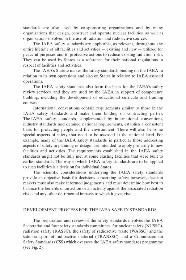
The preparation and review of the safety standards involves the IAEA Secretariat and four safety standards committees, for nuclear safety (NUSSC), radiation safety (RASSC), the safety of radioactive waste (WASSC) and the safe transport of radioactive material (TRANSSC), and a Commission on Safety Standards (CSS) which oversees the IAEA safety standards programme (see Fig. 2).

All IAEA Member States may nominate experts for the safety standards committees and may provide comments on draft standards. The membership of the Commission on Safety Standards is appointed by the Director General and includes senior governmental officials having responsibility for establishing national standards.
A management system has been established for the processes of planning, developing, reviewing, revising and establishing the IAEA safety standards. It articulates the mandate of the IAEA, the vision for the future application of the safety standards, policies and strategies, and corresponding functions and responsibilities.
Secretariat and
consultants:
drafting of new or revision
of existing safety standard
Draft
Endorsement
by the CSS
Final draft
Review by
safety standards
committee(s)Member States
Comments
Draft
Outline and work plan
prepared by the Secretariat;
review by the safety standards
committees and the CSS
FIG. 2. The process for developing a new safety standard or revising an existing standard.
INTERACTION WITH OTHER INTERNATIONAL ORGANIZATIONS
The findings of the United Nations Scientific Committee on the Effects of Atomic Radiation (UNSCEAR) and the recommendations of international
expert bodies, notably the International Commission on Radiological Protection (ICRP), are taken into account in developing the IAEA safety standards. Some safety standards are developed in cooperation with other bodies in the United Nations system or other specialized agencies, including the Food and Agriculture Organization of the United Nations, the United Nations Environment Programme, the International Labour Organization, the OECD Nuclear Energy Agency, the Pan American Health Organization and the World Health Organization.
INTERPRETATION OF THE TEXT
Safety related terms are to be understood as defined in the IAEA Safety Glossary (see http://www-ns.iaea.org/standards/safety-glossary.htm). Otherwise, words are used with the spellings and meanings assigned to them in the latest edition of The Concise Oxford Dictionary. For Safety Guides, the English version of the text is the authoritative version.
The background and context of each standard in the IAEA Safety Standards Series and its objective, scope and structure are explained in Section 1, Introduction, of each publication.
Material for which there is no appropriate place in the body text (e.g. material that is subsidiary to or separate from the body text, is included in support of statements in the body text, or describes methods of calculation, procedures or limits and conditions) may be presented in appendices or annexes.
An appendix, if included, is considered to form an integral part of the safety standard. Material in an appendix has the same status as the body text, and the IAEA assumes authorship of it. Annexes and footnotes to the main text, if included, are used to provide practical examples or additional information or explanation. Annexes and footnotes are not integral parts of the main text. Annex material published by the IAEA is not necessarily issued under its authorship; material under other authorship may be presented in annexes to the safety standards. Extraneous material presented in annexes is excerpted and adapted as necessary to be generally useful.

CONTENTS
1. INTRODUCTION . . . . . . . . . . . . . . . . . . . . . . . . . . . . . . . . . . . . . . . . 1
Background (1.1–1.3) . . . . . . . . . . . . . . . . . . . . . . . . . . . . . . . . . . . . . . 1Objective (1.4–1.5) . . . . . . . . . . . . . . . . . . . . . . . . . . . . . . . . . . . . . . . . 1Scope (1.6–1.11) . . . . . . . . . . . . . . . . . . . . . . . . . . . . . . . . . . . . . . . . . . 2Structure (1.12) . . . . . . . . . . . . . . . . . . . . . . . . . . . . . . . . . . . . . . . . . . 3
2. GENERAL RECOMMENDATIONS (2.1–2.11) . . . . . . . . . . . . . . . . . 4
3. NECESSARY INFORMATION AND INVESTIGATIONS(DATABASE) . . . . . . . . . . . . . . . . . . . . . . . . . . . . . . . . . . . . . . . . . . . 7
Overview (3.1–3.5) . . . . . . . . . . . . . . . . . . . . . . . . . . . . . . . . . . . . . . . 7Geological, geophysical and geotechnical database (3.6–3.23) . . . . . . 8Seismological database (3.24–3.33) . . . . . . . . . . . . . . . . . . . . . . . . . . . 12
4. CONSTRUCTION OF A REGIONAL SEISMOTECTONICMODEL . . . . . . . . . . . . . . . . . . . . . . . . . . . . . . . . . . . . . . . . . . . . . . . 15
General (4.1–4.13) . . . . . . . . . . . . . . . . . . . . . . . . . . . . . . . . . . . . . . . . 15Seismogenic structures (4.14–4.27) . . . . . . . . . . . . . . . . . . . . . . . . . . . 18Zones of diffuse seismicity (4.28–4.32) . . . . . . . . . . . . . . . . . . . . . . . . 20
5. EVALUATION OF THE GROUND MOTION HAZARD . . . . . . . . 21
General (5.1–5.4) . . . . . . . . . . . . . . . . . . . . . . . . . . . . . . . . . . . . . . . . . 21Characterization of ground motion (5.5–5.15) . . . . . . . . . . . . . . . . . . . 22
6. PROBABILISTIC SEISMIC HAZARD ANALYSIS . . . . . . . . . . . . 26
General (6.1–6.5) . . . . . . . . . . . . . . . . . . . . . . . . . . . . . . . . . . . . . . . . . 26Hazard integral (6.6). . . . . . . . . . . . . . . . . . . . . . . . . . . . . . . . . . . . . . . 27
7. DETERMINISTIC SEISMIC HAZARD ANALYSIS . . . . . . . . . . . . 28
8. POTENTIAL FOR FAULT DISPLACEMENT AT THE SITE . . . . . 29
General (8.1–8.2) . . . . . . . . . . . . . . . . . . . . . . . . . . . . . . . . . . . . . . . . . 29Capable faults (8.3–8.7) . . . . . . . . . . . . . . . . . . . . . . . . . . . . . . . . . . . . 30

Capable fault issues for new sites (8.8) . . . . . . . . . . . . . . . . . . . . . . . . 31Capable fault issues for sites with existing nuclear power plants
(8.9–8.13). . . . . . . . . . . . . . . . . . . . . . . . . . . . . . . . . . . . . . . . . . . 31
9. DESIGN BASIS GROUND MOTION, FAULT DISPLACEMENTAND OTHER HAZARDS . . . . . . . . . . . . . . . . . . . . . . . . . . . . . . . . . 32
Levels of ground motion hazard (9.1–9.2) . . . . . . . . . . . . . . . . . . . . . . 32Design basis response spectra (9.3–9.6) . . . . . . . . . . . . . . . . . . . . . . . . 33Time histories (9.7–9.15) . . . . . . . . . . . . . . . . . . . . . . . . . . . . . . . . . . . 34Fault displacement (9.16) . . . . . . . . . . . . . . . . . . . . . . . . . . . . . . . . . . . 37Evaluation of other hazards associated with earthquakes (9.17) . . . . . 37
10. EVALUATION OF SEISMIC HAZARDS FOR NUCLEAR INSTALLATIONS OTHER THAN NUCLEAR POWER PLANTS (10.1–10.11) . . . . . . . . . . . . . . . . . . . . . . . . . . . . . . . . . . . . . . . . . . . . . 37
11. PROJECT MANAGEMENT SYSTEM . . . . . . . . . . . . . . . . . . . . . . . 41
Specific aspects of project organization (11.1–11.14) . . . . . . . . . . . . . 41Engineering uses and output specification (11.15–11.17) . . . . . . . . . . 43Independent peer review (11.18–11.20) . . . . . . . . . . . . . . . . . . . . . . . . 45
REFERENCES . . . . . . . . . . . . . . . . . . . . . . . . . . . . . . . . . . . . . . . . . . . . . . . 47
ANNEX: TYPICAL OUTPUT OF PROBABILISTIC SEISMICHAZARD ANALYSES . . . . . . . . . . . . . . . . . . . . . . . . . . . . . . . 49
DEFINITIONS . . . . . . . . . . . . . . . . . . . . . . . . . . . . . . . . . . . . . . . . . . . . . . . 51
CONTRIBUTORS TO DRAFTING AND REVIEW . . . . . . . . . . . . . . . . . 55
BODIES FOR THE ENDORSEMENT OFIAEA SAFETY STANDARDS . . . . . . . . . . . . . . . . . . . . . . . . . . . . . . . . . . 57

1. INTRODUCTION
BACKGROUND
1.1. This Safety Guide was prepared under the IAEA programme for safety standards for nuclear installations. It supplements the Safety Requirements publication on Site Evaluation for Nuclear Installations [1]. The present publication provides guidance and recommends procedures for the evaluation of seismic hazards for nuclear power plants and other nuclear installations. It supersedes Evaluation of Seismic Hazards for Nuclear Power Plants, IAEA Safety Standards Series No. NS-G-3.3 (2002).
1.2. In this publication, the following was taken into account: the need for seismic hazard curves and ground motion spectra for the probabilistic safety assessment of external events for new and existing nuclear installations; feedback of information from IAEA reviews of seismic safety studies for nuclear installations performed over the previous decade; collective knowledge gained from recent significant earthquakes; and new approaches in methods of analysis, particularly in the areas of probabilistic seismic hazard analysis and strong motion simulation.
1.3. In the evaluation of a site for a nuclear installation, engineering solutions will generally be available to mitigate, by means of certain design features, the potential vibratory effects of earthquakes. However, such solutions cannot always be demonstrated to be adequate for mitigating the effects of phenomena of significant permanent ground displacement such as surface faulting, subsidence, ground collapse or fault creep.
OBJECTIVE
1.4. The objective of this Safety Guide is to provide recommendations and guidance on evaluating seismic hazards at a nuclear installation site and, in particular, on how to determine: (a) the vibratory ground motion hazards, in order
1
to establish the design basis ground motions and other relevant parameters for both new and existing nuclear installations; and (b) the potential for fault displacement and the rate of fault displacement that could affect the feasibility of the site or the safe operation of the installation at that site.

1.5. This Safety Guide is intended for use by regulatory bodies responsible for establishing regulatory requirements, and for operating organizations directly responsible for the assessment of seismic hazards at a nuclear installation site.
SCOPE
1.6. The guidance and procedures recommended in this Safety Guide can appropriately be used in site evaluations and in evaluations of seismic hazards for nuclear installations in any seismotectonic environment.
1.7. Other seismic hazard phenomena involving permanent ground displacement (e.g. liquefaction, slope instability, subsidence, ground collapse, seismically induced soil settlements) as well as seismically induced floods are treated in detail in the Safety Guides relating to geotechnical aspects of site evaluation and foundations and to external floods (see Refs [2, 3], respectively).
1.8. This Safety Guide addresses an extended range of nuclear installations as defined in Ref. [4]: land based stationary nuclear power plants, research reactors, nuclear fuel fabrication facilities, enrichment facilities, reprocessing facilities and independent spent fuel storage facilities. The methodologies recommended for nuclear power plants are applicable to other nuclear installations by means of a graded approach, whereby these recommendations can be customized to suit the needs of nuclear installations of different types in accordance with the potential radiological consequences of their failure when subjected to seismic loads. The recommended direction of grading is to start with attributes relating to nuclear power plants and eventually to grade down to installations with which lesser radiological consequences are associated1. If no grading is performed, the recommendations relating to nuclear power plants are applicable to other types of nuclear installations.
1.9. This Safety Guide addresses issues relating to site evaluation for nuclear installations. Design related seismic safety aspects of nuclear power plants are covered in Ref. [5].
2
1.10. For the purpose of this Safety Guide, existing nuclear installations are those installations that are: (a) at the operational stage (including long term operation
1 For sites at which nuclear installations of different types are collocated, particular consideration should be given to using a graded approach.

and extended temporary shutdown periods); (b) at a pre-operational stage for which the construction of structures, the manufacturing, installation and/or assembly of components and systems, and commissioning activities are significantly advanced or fully completed; or (c) at temporary or permanent shutdown stage while nuclear fuel is still within the facility (in the core or the pool). In existing nuclear installations that are at the operational and pre-operational stages, a change of the original design bases may lead to a significant impact on the design and, consequently, to important hardware modifications [6]. Such a change in the original design bases may be made for a new seismic hazard at the site or a change in the regulatory requirements regarding the consideration of seismic hazards and/or seismic design of the installation.
1.11. The probabilistic seismic hazard analysis recommended in this Safety Guide also addresses what is needed for probabilistic safety assessments (PSAs) conducted for nuclear installations. In accordance with Ref. [7], seismic PSAs are required for seismic evaluation of nuclear power plants.
STRUCTURE
1.12. Recommendations of a general nature are provided in Section 2. The acquisition of a database containing the information needed to evaluate and address all hazards associated with earthquakes is discussed in Section 3. Section 4 covers the use of this database for the construction of a seismotectonic model. Section 5 reviews vibratory ground motion hazards using the databases developed (Section 3) and the seismotectonic model (Section 4). Sections 6 and 7 discuss probabilistic and deterministic methods of evaluating vibratory ground motion hazards. Section 8 reviews methods for evaluation of the potential for fault displacement. Section 9 discusses the development of design basis ground motion and fault displacement. Sections 3 to 9 provide detailed guidance for nuclear power plants. Section 10 discusses the evaluation of seismic hazards for nuclear installations other than nuclear power plants using a graded approach. Section 11 addresses project management, including quality assurance and peer review requirements. The annex provides an example of typical output deriving from probabilistic seismic hazard analyses.
3

2. GENERAL RECOMMENDATIONS
2.1. As established in the Safety Requirements publication, Site Evaluation for Nuclear Installations [1]:
“The seismological and geological conditions in the region and the engineering geological aspects and geotechnical aspects of the proposed site area shall be evaluated.” (Ref. [1], para. 3.1.)
“The hazards associated with earthquakes shall be determined by means of seismotectonic evaluation of the region with the use to the greatest possible extent of the information collected.” (Ref. [1], para. 3.3.)
“Hazards due to earthquake induced ground motion shall be assessed for the site with account taken of the seismotectonic characteristics of the region and specific site conditions. A thorough uncertainty analysis shall be performed as part of the evaluation of seismic hazards.” (Ref. [1], para. 3.4.)
“The potential for surface faulting (i.e. the fault capability) shall be assessed for the site. . . .” (Ref. [1], para. 3.5.)
Detailed requirements are also included in Ref. [1], paras 3.2, 3.6 and 3.7.
2.2. In accordance with these requirements and in line with international practice, the geological, geophysical and seismological characteristics of the region around the site and the geotechnical characteristics of the site area should be investigated as recommended in this Safety Guide for the purpose of evaluating the seismic hazards at the nuclear installation site.
2.3. Where necessary, the site region should include areas extending beyond national borders and the relevant offshore area for sites located near a coastline. The database acquired should be homogeneous for the entire region to the extent possible or, at a minimum, should be sufficiently complete for characterizing,
4
from a seismotectonic point of view, features relevant to the site that are located in other States or in offshore areas.
2.4. The size of the region to be investigated, the type of information to be collected and the scope and detail of the investigations should be determined in accordance with the nature and complexity of the seismotectonic environment. In
all cases, the scope and detail of the information to be collected and the investigations to be undertaken should be sufficient for determining the vibratory ground motion and fault displacement hazards. If the site is close to major tectonic structures such as plate boundaries, thrust zones and subduction zones, including those in offshore areas, these structures should be considered in the investigations not only as seismogenic but also as features that may strongly affect the travel path and the site response.
2.5. The seismic hazard evaluation should be done through implementation of a specific project for which clear and detailed objectives are defined, and in accordance with a work plan, as recommended in Section 11 of this Safety Guide. This seismic hazard evaluation project should be carried out by a multidisciplinary team of experts, including geologists, seismologists, geophysicists, engineers and possibly other experts (e.g. historians). The members of the team for the seismic hazard evaluation project should demonstrate the expertise and experience commensurate with their role in the project.
2.6. The general approach to seismic hazard evaluation should be directed towards reducing the uncertainties at various stages of the evaluation process in order to obtain reliable results driven by data. Experience shows that the most effective way of achieving this is to collect a sufficient amount of reliable and relevant data. There is generally a trade-off between the time and effort necessary to compile a detailed, reliable and relevant database and the degree of uncertainty that the analyst should take into consideration at each step of the process.
2.7. The collection of site specific data tends to reduce uncertainties. However, part of the data used indirectly in seismic hazard evaluation may not be site specific; for example, in many cases the strong motion data used to develop the attenuation relationships. There may be, therefore, a part of the uncertainty which is irreducible with respect to site specific investigations. This should be recognized and taken into consideration by including aleatory uncertainty (i.e. uncertainty that is intrinsic or random in nature) and epistemic uncertainty (i.e. uncertainty that is extrinsic in nature or is associated with modelling) within the framework of seismic hazard evaluation.
5
2.8. The overall uncertainty will involve both aleatory uncertainties, and epistemic uncertainties that arise owing to differences in interpretation on the part of informed experts participating in the seismic hazard evaluation. Every aspect of the identification, analysis and characterization of seismic sources and estimation of ground motion hazards may involve subjective interpretation by

experts. By taking due consideration of this, such interpretations should be treated in the seismic hazard analysis in a consistent manner, providing for a suitable representation of current thinking in seismic source and ground motion modelling. Particular care should be taken to avoid bias in these interpretations. Expert opinion should not be used as a substitute for acquiring new data. The project team for the seismic hazard evaluation should not promote any one expert hypothesis or model. It should, however, evaluate all viable hypotheses and models using the data compiled, and then develop an integrated evaluation that incorporates both knowledge and uncertainties.
2.9. To cover the diversity of scientific interpretations, one approach is to involve a team of experts qualified in each of the relevant disciplines. When such an approach is not feasible, an alternative approach to hazard analysis can be taken. In such a case, it should be demonstrated that a similar level of uncertainty in the input can still be represented. This may be possible by developing a detailed analysis of relevant data and scientific research and by incorporating into the analysis all scientifically valid alternative hypotheses, associated uncertainties and sensitivity analyses. A systematically conducted sensitivity analysis should be used to support the evaluation of the significance of the contributions of the various input data in the model.
2.10. Uncertainties that cannot be reduced by means of site investigations (e.g. uncertainties arising from the use of ground motion attenuation relationships derived for other parts of the world) do not permit hazard values to decrease below certain threshold values. For this reason, and regardless of any lower apparent exposure to seismic hazard, a minimum level should be recognized as the lower limit to any seismic hazard study performed for a nuclear power plant using this Safety Guide.
2.11. In that regard, generically, this level should be represented by a horizontal free field standardized response spectrum anchored to a peak ground acceleration value of 0.1g (where ‘g’ is the acceleration due to gravity). It should also be recognized that when geological and seismological data have deficiencies in comparison with what is recommended in Section 3, the value of 0.1g will not represent a sufficiently conservative estimate of the hazard. This fact should be
6
properly represented in defining the design basis and re-evaluation parameters discussed in Refs [5, 6], respectively.

3. NECESSARY INFORMATION AND INVESTIGATIONS (DATABASE)
OVERVIEW
3.1. A comprehensive and integrated database of geological, geophysical, geotechnical and seismological information should be acquired and incorporated in a coherent form for evaluating and resolving issues relating to all hazards associated with earthquakes.
3.2. It should be ensured that each element of every database has been investigated as fully as possible before an integration of the various elements is attempted. The integrated database should include all relevant information; that is, not only geological, geophysical, geotechnical and seismological data, but also any other information that is relevant to evaluating the ground motion, faulting and geological hazards at the site.
3.3. Investigations should be conducted on four spatial scales — regional, near regional, site vicinity and site area — leading to progressively more detailed investigations, data and information. The detail of these data is determined by the different spatial scales. The first three scales of investigation lead primarily to progressively more detailed geological and geophysical data and information. The site area investigations are aimed at developing the geotechnical database. To achieve consistency in the presentation of information, whenever possible the data should be compiled in a geographical information system with adequate metadata information. All data should be stored in a uniform reference frame to facilitate comparison and integration.
3.4. The compilation of the seismological database will normally be less dependent on the regional, near regional and site vicinity scales than that of other databases. However, seismogenic structures in the near region and in the site vicinity will usually be more important for seismic hazard evaluation, depending on the rates of activity, the expected maximum potential magnitudes and the regional attenuation of ground motion. Particularly for some intraplate tectonic
7
settings, attention should be paid to compiling seismological data for more distant seismic sources that may be beyond the typical boundaries of the region. In offshore regions, adequate investigations should be conducted in order to fully analyse the tectonic characteristics of the region and to compensate for any lack of or deficiency in the seismological data.
3.5. When a seismic hazard analysis is performed for any reason during the operating lifetime of the nuclear power plant (e.g. for a periodic safety review or a probabilistic seismic hazard analysis for a seismic probabilistic safety assessment), the integrated database should be updated to cover the time elapsed from the most recent compilation of data until the present, and recent scientific findings should be incorporated.
GEOLOGICAL, GEOPHYSICAL AND GEOTECHNICAL DATABASE
3.6. As established in Ref. [1], para. 2.19: “The size of the region to which a method for establishing the hazards associated with major external phenomena is to be applied shall be large enough to include all the features and areas that could be of significance in the determination of the natural and human induced phenomena under consideration and for the characteristics of the event.”
Regional investigations
3.7. The size of the relevant region may vary, depending on the geological and tectonic setting, and its shape may be asymmetric in order to include distant significant seismic sources of earthquakes. Its radial extent is typically 300 km. In intraplate regions, and in the particular case of investigations into the potential for tsunamis (Ref. [3]), the investigations may need to consider seismic sources at very great distances from the site. If it can be demonstrated easily that there are major tectonic structures closer to the site than the radius indicated, then studies should concentrate on this part of the region.
3.8. The purpose of obtaining data on a regional scale is to provide knowledge of the general geodynamic setting of the region and the current tectonic regime, as well as to identify and characterize those geological features that may influence or relate to the seismic hazard at the site. The most relevant among these geological features are structures that show potential for displacement and/or deformation at or near the ground surface; that is, capable faults. The data obtained from any type of published and unpublished geological and geophysical source (e.g. data derived from existing galleries, road cuts, geophysical surveys
8
or boreholes) should be presented on maps with appropriate cross-sections.
3.9. Where existing data are inadequate for the purpose of delineating seismogenic structures, in terms of location, extent and rate of ongoing deformation, it may be necessary to verify and complete the database by acquiring new geological and geophysical data. This may involve investigations

at the scale (detail) of the near region and site vicinity to assess the potential seismogenic features located outside the near region. Identification of the ground effects of prehistoric and historical earthquakes on the geological and geomorphological environment (i.e. palaeoseismology, see para. 4.13) is also useful for this purpose.
3.10. The data are typically presented on maps at a scale of 1:500 000 or larger, and with appropriate cross-sections.
Near regional investigations
3.11. Near regional studies should include a geographical area typically not less than 25 km in radius, although this dimension should be adjusted to reflect local conditions. The objectives of these studies are to:
(1) Define the seismotectonic characteristics of the near region on the basis of a more detailed database than that obtained from the regional study;
(2) Determine the latest movements of faults;(3) Determine the amount and nature of displacements, rates of activity and
evidence related to the segmentation of faults.
3.12. To supplement the published and unpublished information for the near regional area, specific investigations typically should include a definition of the stratigraphy, structural geology and tectonic history of the near region. The tectonic history should be thoroughly defined for the present tectonic regime, the length of which will depend on the rate of tectonic activity. For example, for studies to assess fault capability, the tectonic information through the Upper Pleistocene–Holocene (i.e. the present) may be adequate for interplate regions and that through the Pliocene–Quaternary (i.e. the present) for intraplate regions. Age dating, by any reliable and applicable method, should be performed. In addition to field mapping, other sources of data should be used if necessary, for example:
(a) Subsurface data derived from geophysical investigations (such as seismic reflection, refraction, gravimetric, electric and magnetic techniques), to
9
characterize spatially the identified structures considered to be relevant in terms of their geometry, extent and rate of deformation. Use of heat flow data may also be necessary. These data are of primary importance in dealing with offshore areas (for sites located on or near a coastline).
(b) Surface data derived from studies of Quaternary formations or land forms, such as terrace analysis and pedological and sedimentological studies. Use should be made of aerial and satellite photographs and/or images for this task.
(c) For understanding the ongoing rate and type of deformation, use should also be made of data derived by recently developed technological means such as global positioning system data and interferometry data, and of data derived from strain rate measurements.
3.13. For some relevant structures identified in the near regional investigations, it may be necessary to conduct additional geological and geophysical studies at the site vicinity scale in order to obtain the desired detail of characterization (see para. 4.13).
3.14. Investigations should be made in sufficient detail so that the causes of each recent (in terms of the pertinent time window for the specific local tectonic environment) geological and geomorphological feature that is relevant (e.g. linear topographic or structural features as found in photographs, remote sensing imagery or geophysical data) can be properly included in a reasonable model of the recent geological evolution of the area.
3.15. The data are typically presented on maps at a scale of 1:50 000 and with appropriate cross-sections.
Site vicinity investigations
3.16. Site vicinity studies should cover a geographical area typically not less than 5 km in radius. In addition to providing a yet more detailed database for this smaller area, the objective of these investigations is to define in greater detail the neotectonic history of the faults, especially for determining the potential for and rate of fault displacement at the site (fault capability), and to identify conditions of potential geological instability of the site area.
3.17. Investigations of the site vicinity typically should include geomorphological and geological mapping, geophysical investigations and profiling, boreholes and trenching (see Section 8), and the data to be provided
10
should be consistent with the tectonic environment and the geological features observed. As a minimum, the following data sets should be provided:
(a) A geological map with cross-sections; (b) Age, type, amount and rate of displacement of all the faults in the area;

(c) Identification and characterization of locations potentially exhibiting hazards induced by natural phenomena (e.g. landslide, subsidence, subsurface cavities or karstic processes) and by human activities.
3.18. Typically, the data are presented on maps at a scale of 1:5000 and with appropriate cross-sections.
Site area investigations
3.19. Site area studies should include the entire area covered by the nuclear power plant, which is typically one square kilometre. The primary objective of these investigations is to obtain detailed knowledge of the potential for permanent ground displacement phenomena associated with earthquakes (e.g. fault capability, liquefaction, subsidence or collapse due to subsurface cavities) and to provide information on the static and dynamic properties of foundation materials (such as P-wave and S-wave velocities), to be used in site response analysis as defined in detail in Ref. [6].
3.20. The database should be developed from detailed geological, geophysical and geotechnical studies, including in situ and laboratory testing.
3.21. The following investigations of the site area should be performed, by using field and laboratory techniques:
(a) Geological and geotechnical investigations to define the stratigraphy and the structure of the area: Investigations using boreholes or test excavations (including in situ testing), geophysical techniques and laboratory tests should be conducted to define the stratigraphy and structure of the site areaand to determine the thickness, depth, dip, and static and dynamic properties of the different subsurface layers as may be required by engineering models (e.g. Poisson’s ratio, Young’s modulus, shear modulus, density, relative density, shear strength and consolidation characteristics, grain size distribution).
(b) Hydrogeological investigations: Investigations using boreholes and other techniques should be conducted to define the geometry, physical and
11
chemical properties, and steady state behaviour (e.g. water table depth, recharge rate, transmissivity) of all aquifers in the site area, with the specific purpose of determining the stability of soils and how they interact with the foundation.

(c) Supplemental investigations of site effects: The dynamic behaviour of the site should be assessed, using available macroseismic and instrumental information as guidance.
3.22. All the data required for assessing the dynamic soil–structure interaction should be acquired in the course of these investigations. For completeness and efficiency, the investigations described in paras 3.19 and 3.20 should be integrated with the investigations required for the dynamic soil–structure interaction as described in Ref. [2].
3.23. The data are typically presented on maps at a scale of 1:500 and with appropriate cross-sections.
SEISMOLOGICAL DATABASE
3.24. As established in Ref. [1], para. 3.2: “Information on prehistorical, historical and instrumentally recorded earthquakes in the region shall be collected and documented.” A catalogue — the site earthquake catalogue — should be compiled that includes all earthquake related information developed for the project covering all those temporal scales.
Prehistoric and historical earthquake data (pre-instrumental data)
3.25. All pre-instrumental data on historical earthquakes (that is, events for which no instrumental recording was possible) should be collected, extending as far back in time as possible. Palaeoseismic and archaeological information on historical and prehistoric earthquakes should also be taken into account.
3.26. To the extent possible, the information on each earthquake should include:
(a) Date, time and duration of the event; (b) Location of the macroseismic epicentre;(c) Estimated focal depth;(d) Estimated magnitude, the type of magnitude (e.g. moment magnitude,
12
surface wave magnitude, body wave magnitude, local magnitude or duration magnitude; see Definitions) and documentation of the methods used to estimate magnitude from the macroseismic intensity;
(e) Maximum intensity and, if different, intensity at the macroseismic epicentre, with a description of local conditions and observed damage;
(f) Isoseismal contours;

(g) Intensity of the earthquake at the site, together with any available details of effects on the soil and the landscape;
(h) Estimates of uncertainty for all of the parameters mentioned;(i) An assessment of the quality and quantity of data on the basis of which such
parameters have been estimated;(j) Information on felt foreshocks and aftershocks;(k) Information on the causative fault.
The intensity scale used in the catalogue should be specified, since intensity levels can vary, depending on the scale used. The magnitude and depth estimates for each earthquake should be based on relevant empirical relationships between instrumental data and macroseismic information, which may be developed from the database directly from intensity data or by using isoseismals.
Instrumental earthquake data
3.27. All available instrumental earthquake data should be collected. Existing information on crustal models should be obtained in order to locate earthquakes. The information to be obtained for each earthquake should include:
(a) Date, duration and time of origin; (b) Coordinates of the epicentre;(c) Focal depth;(d) All magnitude determinations, including those on different scales, and any
information on seismic moment;(e) Information on observed foreshocks and aftershocks, with their dimensions
and geometry where possible;(f) Other information that may be helpful in understanding the seismotectonic
regime, such as focal mechanism, seismic moment, stress drop and other seismic source parameters;
(g) Macroseismic details as discussed in para. 3.26;(h) Asperity location and size; (i) Estimates of uncertainty for each of the parameters mentioned;(j) Information on the causative fault, directivity and duration of rupture;(k) Records from both broadband seismometers and strong motion
13
accelerographs.
3.28. When the catalogue of prehistoric, historical and instrumental earthquake data has been compiled, an assessment of the completeness and reliability of the information it contains, particularly in terms of macroseismic intensity, magnitude, date, location and focal depth, should be conducted. In general, the

catalogues are incomplete for small magnitude events owing to the threshold of recording sensitivity, and they are incomplete for large magnitude events owing to their long recurrence intervals (and the comparatively short period of coverage of the catalogues). Appropriate methods should be used to take account of this incompleteness.
3.29. Wherever possible, available recordings of regional and local strong ground motion should be collected and used for deriving or selecting appropriate ground motion attenuation relationships and in developing response spectra as discussed in Section 9.
Project specific instrumental data
3.30. To acquire more detailed information on potential seismic sources, it is recommended that a network of sensitive seismographs having a recording capability for micro-earthquakes be installed and operated. The minimum monitoring period necessary to obtain meaningful data for seismotectonic interpretation is at least several years for regions of high seismicity, and is much longer for regions of low seismicity. It is advisable to link the operation and data processing, data interpretation, and reporting of the local micro-earthquake network to the regional and/or national seismic networks. If the selected instrumentation for this purpose cannot adequately record strong motion earthquakes, consideration should be given to collocating several strong motion accelerographs with the sensitive seismographs.
3.31. Earthquakes recorded within and near such a network should be carefully analysed in connection with seismotectonic studies of the near region.
3.32. Strong motion accelerographs should be installed permanently within the site area in order to record small and large earthquakes (Ref. [5]). Weak and strong motion instrumentation using vertical and horizontal arrays should be used for a better understanding of buried structures and site response. A stratigraphic profile with dynamic soil properties below the network stations should be obtained.
14
3.33. This instrumentation should be appropriately and periodically upgraded and calibrated to provide adequate information in line with updated international operational practice. A maintenance programme, including data communication aspects, should be in place to ensure that no significant lapses occur.

4. CONSTRUCTION OF A REGIONALSEISMOTECTONIC MODEL
GENERAL
4.1. The link between the geological, geophysical, geotechnical and seismological databases (Section 3) and the calculation of the seismic hazard (Sections 5–8) is a regional seismotectonic model, which should be based on a coherent merging of the databases. In the construction of such a model, all relevant interpretations of the seismotectonics of the region that may be found in the available literature should be taken into account. Above all, a sound database is essential in the construction of a reliable seismotectonic model. It should be noted that the most sophisticated methods will not yield good models if the database is poor or insufficient.
4.2. The standard procedure is to integrate the elements of the seismological, geophysical and geological databases (see Section 3) in order to construct a coherent seismotectonic model (and alternative models) consisting of a discrete set of seismogenic structures.
4.3. The seismogenic structures identified may not explain all the observed earthquake activity. This is because seismogenic structures may exist without recognized surface or subsurface manifestations, and because of the timescales involved; for example, fault displacements may have long recurrence intervals with respect to seismological observation periods.
4.4. Consequently, any seismotectonic model should consist, to a greater or lesser extent, of two types of seismic source:
(1) Those seismogenic structures that can be identified by using the available database;
(2) Diffuse seismicity (consisting usually, but not always, of small to moderate earthquakes) that is not attributable to specific structures identified by using the available database.
15
4.5. The evaluation and characterization of seismic sources of both types involve assessments of uncertainty. However, seismic sources of the second type, those of diffuse seismicity, pose a particularly complex problem in seismic hazard evaluation and will generally involve greater uncertainty because the causative faults of earthquakes are not well understood.

4.6. An attempt should be made to define all the parameters of each element in a seismotectonic model. The construction of the model should be primarily data driven, and the data should not be interpreted in a manner that supports an individual’s preconception.
4.7. When it is possible to construct alternative models that can explain the observed geological, geophysical and seismological data, and the differences in these models cannot be resolved by means of additional investigations within a reasonable time frame, all such models should be taken into consideration in the final hazard evaluation, with due weight given to each model. The epistemic uncertainty (i.e. the uncertainty associated with the modelling process) should be adequately assessed, to capture the full range of hypotheses regarding the characterization of the seismic sources and the frequencies of the earthquakes.
4.8. Prior to the use of the earthquake catalogue (see para. 3.24) to estimate the magnitude–frequency relationship for a seismic source, considerable evaluation and processing of the catalogue is required. This should include:
(a) Selection of a consistent magnitude scale for use in the seismic hazard analysis;
(b) Determination of the uniform magnitude of each event in the catalogue on the selected magnitude scale;
(c) Identification of main shocks (i.e. declustering of aftershocks); (d) Estimation of completeness of the catalogue as a function of magnitude,
regional location and time period;(e) Quality assessment of the derived data, with uncertainty estimates of all
parameters.
4.9. The magnitude scale selected should be consistent with the magnitude scale used in the ground motion attenuation relationships that are used in the hazard calculations and in any relationships used to derive the earthquake magnitude from intensity data. In deriving magnitude–frequency relationships, the selected magnitude scale should vary close to linearly with the moment magnitude (Mw) scale across the magnitude range of interest, in order to avoid magnitude saturation effects. This is in line with the recognition that the use of Mw is
16
becoming a worldwide standard, owing to its increased use in seismology and the development of attenuation relationships.
4.10. A magnitude–frequency relationship should be developed for each seismic source. Each magnitude–frequency relationship should include the maximum potential magnitude up to which the magnitude–frequency relationship applies.

4.11. Uncertainty in the parameters of the magnitude–frequency relationship should be defined by probability distributions that account for any correlation between the parameters.
4.12. The maximum potential magnitude mmax associated with each seismic source should be specified, and the uncertainty in mmax should be described by a discrete or continuous probability distribution. For each seismic source, the value of mmax is used as the upper limit of integration in a probabilistic seismic hazard calculation and in the derivation of the magnitude–frequency relationship, and as the scenario magnitude in a deterministic seismic hazard evaluation. For sites in intraplate settings, the largest observed earthquake may not be a good estimate of mmax. The use of global analogues is important, and care should be taken to determine the appropriate seismotectonic analogue. The sensitivity of the resulting hazard to the selection of the mmax distributions should be tested.
4.13. Earthquakes produce effects on the environment that are also described in the macroseismic intensity scales. Some of these effects (e.g. faulting, liquefaction, coastline uplift) can be observed to recognize past earthquakes. The study of the geological record of prehistoric and historical earthquakes is referred to as palaeoseismology. Palaeoseismic studies may be particularly useful in areas for which historical earthquake records are lacking. When appropriate, palaeoseismic studies should be performed by using the database described in Section 3 for the following purposes:
(a) Identification of seismogenic structures on the basis of the recognition of effects of past earthquakes in the region.
(b) Improvement of the completeness of earthquake catalogues for large events, using identification and age dating of fossil earthquakes. For example, observations of trenching across the identified capable faults may be useful in estimating the amount of displacement (e.g. from the thickness of colluvial wedges) and its rate of occurrence (e.g. by using age dating of the sediments). Regional studies of palaeo-liquefaction can provide evidence of the recurrence and intensity of earthquakes.
(c) Estimation of the maximum potential magnitude of a given seismogenic structure, typically on the basis of the maximal length of the structure and
17
displacement per event (trenching) as well as of the cumulative effect (seismic landscape).
(d) Calibration of probabilistic seismic hazard analyses, using the recurrence intervals of large earthquakes.
SEISMOGENIC STRUCTURES
Identification
4.14. All seismogenic structures that may have significance for contributing to the ground motion and fault displacement hazard at the site should be included in the seismotectonic model.
4.15. With regard to the ground motion hazard, the concern lies with those seismogenic structures whose combination of location and earthquake potential could contribute to the seismic hazard at the site over the range of ground motion frequencies of interest.
4.16. With regard to the fault displacement hazard, the concern lies with those seismogenic structures close to the site that have a potential for displacement at or near the ground surface (i.e. capable faults, see Section 8).
4.17. The identification of seismogenic structures should be made from the geological, geophysical, geotechnical and seismological databases (see Section 3) on the basis of those geological features for which there is direct or indirect evidence of their having been a seismic source within the current tectonic regime. The correlation of historical and instrumental recordings of earthquakes with geological and geophysical features is particularly important in identifying seismogenic structures, although a lack of correlation does not necessarily indicate that a structure is not seismogenic.
4.18. Whenever the investigations described in Section 3 show that an earthquake hypocentre or a group of earthquake hypocentres can potentially be associated with a geological feature, the rationale for this association should be developed by considering the characteristics of the feature, its geometry and geographical extent, and its structural relationship to the regional tectonic framework.
4.19. Other available seismological information (such as information on uncertainties in hypocentral parameters and the earthquakes’ focal mechanisms, stress environments and foreshock and aftershock distributions) should also be
18
used in considering any association of earthquake hypocentres with geological features.
4.20. When specific data on a particular geological feature are lacking or sparse, a detailed comparison of this feature with other analogous geological features in the region should be made in terms of their age of origin, sense of movement and

history of movement, to help determine whether the feature can be considered seismogenic.
4.21. The incorporation of seismogenic structures into a seismotectonic model should be done firmly on the basis of the available data and should incorporate uncertainties in the identification of these structures. Unsupported assumptions or opinions with regard to the association between earthquakes and geological features should not be considered an appropriate assessment of uncertainty. However, the lack of data on a geological feature should not by itself be considered a sufficient reason to treat the feature as not seismogenic.
Characterization
4.22. For seismogenic structures that have been identified as being pertinent to determining the exposure of the site to earthquake hazards, their associated characteristics should be determined. The dimensions of the structure (length, down-dip, width), orientation (strike, dip), amount and direction of displacement, rate of deformation, maximum historical intensity and magnitude, palaeoseismic data, geological complexity (segmentation, branching, structural relationships), earthquake data and comparisons with similar structures for which historical data are available should be used in this determination.
4.23. When sufficient information about the seismological and geological history of the movement of a fault or structure (such as segmentation, average stress drop and fault width) is available to allow estimates to be made of the maximum rupture dimensions and/or displacements of future earthquakes, this information together with empirical relationships may be used to evaluate the maximum potential magnitude. A number of other data that may be used to construct a rheological profile are also important in this estimation, such as data on heat flow, crustal thickness and strain rate.
4.24. In the absence of suitably detailed data, the maximum potential magnitude of a seismogenic structure can be estimated from its total dimensions. For a fault source, the maximum magnitude can be estimated using the fault’s length and depth as well as the stress regime impinging on it. In locations where a fault zone
19
comprises multiple fault segments, each fault should be taken into account independently. The possibility of the multiple fault segments rupturing simultaneously during a single earthquake should also be analysed. In order to deal with mmax uncertainties, a suite of possible fault rupture length scenarios should be developed and used to determine the best estimate for mmax values on that fault.

4.25. Other approaches are available for estimating maximum potential magnitudes on the basis of statistical analysis of the magnitude–frequency relationships for earthquakes associated with a particular structure. These approaches assume an association between the structure and all the earthquake data used. In all cases, the results of these methods should be confirmed to be consistent with the data.
4.26. Regardless of the approach or combination of approaches used, the determination of the maximum potential magnitude may have significant uncertainty, which should be incorporated to the extent that it is consistent with geological and geomorphological data.
4.27. In addition to the maximum potential magnitude, a magnitude–frequency relationship should be derived for each seismogenic structure included in the seismotectonic model, to determine: (a) the rate of earthquake activity; (b) an appropriate type of magnitude–frequency relationship (e.g. characteristic or exponential); and (c) the uncertainty in this relationship and its parameters.
ZONES OF DIFFUSE SEISMICITY
Identification
4.28. Seismotectonic provinces should be used to represent zones of diffuse seismicity in which each seismotectonic province is assumed to encompass an area having equal seismic potential (i.e. a geographically uniform rate of seismicity). A geographically non-uniform distribution of seismicity can also be used provided that the available data support this assumption.
4.29. In the performance of a seismic hazard evaluation, knowledge about the depth distribution of the diffuse seismicity (e.g. derived from the seismological database) should be incorporated. Estimates of the maximum depth of earthquakes can be made on the basis of the recognized fact that earthquakes originate within or above the brittle to ductile transition zone of the Earth’s crust.
20
4.30. Significant differences in rates of earthquake occurrence may suggest different tectonic conditions and may be used in defining the boundaries of the seismotectonic provinces. Significant differences in focal depths (e.g. crustal versus subcrustal), focal mechanisms, states of stress, tectonic characteristics and Gutenberg–Richter b values may all be used to differentiate between provinces or zones.

Characterization
4.31. The maximum potential magnitude not associated with identified seismogenic structures should be evaluated on the basis of historical data and the seismotectonic characteristics of the zone. Comparison with similar regions for which extensive historical data are available may be useful, but considerable judgement may be used in such an evaluation. Often the value of maximum potential magnitude obtained will have significant uncertainty owing to the relatively short time period covered by the historical data with respect to the processes of ongoing deformation. This uncertainty should be appropriately represented in the seismotectonic model.
4.32. For seismic sources that have few earthquakes, determination of the Gutenberg–Richter b value may involve a different approach, which may include adopting a value that represents the regional tectonic setting of the seismic source; for example, a stable continental tectonic setting. This approach is viable because many studies have shown that the b value varies over a relatively narrow range within a given tectonic setting. Regardless of the approach used to determine the b value of the magnitude–frequency relationship, uncertainty in the parameter should be appropriately assessed and incorporated into the seismic hazard analysis.
5. EVALUATION OF THE GROUND MOTION HAZARD
GENERAL
5.1. The ground motion hazard should preferably be evaluated by using both probabilistic and deterministic methods of seismic hazard analysis. When both deterministic and probabilistic results are obtained, deterministic assessments can be used as a check against probabilistic assessments in terms of the reasonableness of the results, particularly when small annual frequencies of
21
exceedance are considered. The probabilistic results allow deterministic values to be evaluated within a probabilistic framework so that the annual frequency of exceedance of each spectral ordinate of the deterministic response spectrum is known.
5.2. In the seismic hazard evaluation, all uncertainties — both aleatory and epistemic — should be taken into account. In a deterministic seismic hazard analysis as recommended in this Safety Guide, uncertainties are incorporated by using a conservative process at each step of the evaluation. These steps are described in para. 7.1. The probabilistic seismic hazard analysis should provide a realistic assessment and should incorporate uncertainties explicitly in the analysis.
5.3. When conducting studies for seismic probabilistic safety assessment as required in Safety of Nuclear Power Plants: Design [7], the performance of a probabilistic seismic hazard analysis is a requirement. The same requirement applies when a seismic probabilistic safety assessment is to be performed as part of an evaluation of the seismic safety of an existing nuclear power plant. A probabilistic seismic hazard analysis may also be used to support seismic margin assessments for nuclear power plants; for example, in the derivation of the review level earthquake (see Ref. [6]).
5.4. When computer codes are used in the evaluation of the ground motion hazard, they should be able to accommodate the variety of alternative attenuation and seismic source models defined by the project team for the seismic hazard evaluation, for use in the calculations. It should also be demonstrated that these codes account appropriately for the treatment of uncertainties.
CHARACTERIZATION OF GROUND MOTION
5.5. One or more ground motion parameters and, if appropriate, ground motion components should be selected that best meet the objectives of the seismic hazard analysis. The parameters most commonly used to characterize ground motion are response spectral acceleration, velocity or displacement at specified damping levels, ground motion duration and oscillator frequencies. Other parameters include peak ground acceleration, peak ground velocity, peak ground displacement, the average value of response spectral values over a specified range of oscillator frequencies, Fourier amplitude spectrum and power spectral density. The ground motion components that are commonly used are the largest
22
horizontal component, the geometric mean of the two horizontal components, the random horizontal component, the vector sum of the two horizontal components, and the vertical component. The selection of the ground motion parameters and components should be consistent with the requirements of the users of the seismic hazard analysis (see Section 11).
Ground motion prediction models: Attenuation relationships
5.6. The attenuation relationship(s) should express the ground motion as a function of all relevant parameters, using an empirically or theoretically constrained relationship of the form:
(1)
where
GM is the median estimate of the ground motion parameter and ground motion component of interest (usually expressed as a logarithm);
g(…) is a mathematical function;m is the earthquake magnitude;r is the seismic source to site distance;ci are other relevant parameters (e.g. style of faulting, hanging wall
effects and local site conditions);gm is the aleatory uncertainty;c is the component to component variability (i.e. the variability
between the two horizontal components should the random horizontal component of ground motion be used in the seismic hazard analysis).
5.7. The calculated ground motion may express the maximum ground motion or a random component, depending on the project needs (see Section 11). The parameter c is used when the component to component variability needs to be represented.
5.8. It is useful in some situations to divide the aleatory uncertainty into its inter-event or between-earthquake component () and its intra-event or within-earthquake component (). If, for a given attenuation relationship, such a partitioning of the uncertainty is not available, it can be estimated from those attenuation relationships that provide a partitioning of the uncertainty. It should be noted that attenuation relationships are also referred to as ground motion prediction equations because the process that they represent covers more than just
GM g m r ci gm c= + +( , , ) e e
23
attenuation. The term ‘attenuation relationship’, while not fully descriptive, is used in this Safety Guide for historical reasons and for consistency with common usage. A separate relationship may be used for the vertical ground motion.
5.9. Magnitude, distance and the other relevant parameters should be selected to be consistent with those used in the characterization of the seismic sources. If

there is a discrepancy between the parameters used in the selected attenuation relationships and those used in other parts of the seismic hazard analysis, this discrepancy should be mitigated by converting from one parameter to the other by using well established empirical relationships and their corresponding uncertainties. The range of magnitudes for which the attenuation relationship is valid should be checked.
5.10. The attenuation relationships should be compatible with the reference site condition. If these conditions are not the same, an adjustment should be made using empirical or theoretical site response factors and their corresponding uncertainty.
5.11. Attenuation relationships should be selected to meet the following general criteria: they should be current and well established at the time of the study; they should be consistent with the types of earthquake and the attenuation characteristics of the region of interest; they should match as closely as possible the tectonic environment of the region of interest; and they should make use of local ground motion data where available. Caution should be exercised in comparing selected attenuation relationships with recorded ground motions from small, locally recorded earthquakes. The use of such recordings (e.g. in scaling the selected attenuation relationships) should be justified by showing that their inferred magnitudes and distance scaling properties are appropriate for earthquakes within the ranges of magnitude and distance that are of greatest concern with regard to the seismic safety of the nuclear power plant.
5.12. Epistemic uncertainty should be included by using multiple attenuation relationships suitable for each tectonic environment represented in the analysis. These attenuation relationships should be chosen to capture adequately the range of credible interpretations in relevant model characteristics.
5.13. Seismic intensity data may also be used to estimate attenuation relationships in those regions of the world where instruments for recording strong motion have not been in operation for a long enough period of time to provide suitable amounts of instrumental data. These data should be used at least in a qualitative manner to verify that the attenuation relationships used to calculate the
24
seismic hazard are representative of the regional attenuation characteristics.
Ground motion prediction models: Seismic source simulation
5.14. In seismically active regions for which data from ground motion caused by identifiable faults are available in sufficient quantity and detail, simulation of the

fault rupture as well as of the wave propagation path is another procedure that should be followed. In cases where nearby faults contribute significantly to the hazard, this procedure may be especially effective. The parameters needed include:
(a) Fault geometry parameters (location, length, width, depth, dip, strike); (b) Macroparameters (seismic moment, average dislocation, rupture velocity,
average stress drop); (c) Microparameters (rise time, dislocation, stress parameters for finite fault
elements);(d) Crustal structure parameters, such as shear wave velocity, density and
damping of wave propagation (i.e. the wave attenuation Q value).
For complex seismotectonic environments such as plate boundaries, thrust zones and subduction zones, and in particular for offshore areas, the specific seismotectonic setting of the earthquake that affects those seismic source parameters mentioned in (a)–(d) should be considered in the characterization of the ground motion.
5.15. To stay within the range of magnitudes that is represented by the database used in the derivation of the attenuation relationships, it is necessary to use a corresponding lower magnitude limit. The practice has been to combine this lower limit consideration with an engineering concept that is linked to a ground motion level from a magnitude below which no damage would be incurred by the safety related structures, systems and components of the nuclear power plant. It is clear that a magnitude value alone is not the best way of representing damage potential. An alternative to the use of a magnitude measure, the lower bound motion filter, may be specified, therefore, in terms of an established damage parameter, such as the cumulative absolute velocity, in conjunction with a specific value of that parameter for which it can be clearly demonstrated that no significant contribution to damage or risk will occur. The lower bound motion filter should be selected in consultation with the seismic designer and/or the fragility analyst.
25

6. PROBABILISTIC SEISMIC HAZARD ANALYSIS
GENERAL
6.1. The probabilistic seismic hazard analysis should make use of all the elements and parameters of the seismotectonic model (see Section 4), including the quantified uncertainties. When alternative models have been proposed by the team performing the probabilistic seismic hazard analysis, they should be formally included in the probabilistic hazard computation.
6.2. The smallest annual frequency of exceedance of interest will depend on the eventual use of the probabilistic seismic hazard analysis (i.e. whether for design purposes or for input to a seismic probabilistic safety assessment) and should be indicated in the project plan (see Section 11). This value can be extremely low (e.g. 10−8) when it is associated with seismic probabilistic safety assessment studies in which the nuclear power plant has a very low core damage frequency in relation to non-seismic initiators (e.g. for innovative reactors). In such cases, care should be taken to assess the suitability and validity of the database, the seismotectonic model and the basis for the expert opinion, since uncertainties associated with these can significantly bias the hazard results.
6.3. The conduct of a probabilistic seismic hazard analysis should include the following steps:
(1) Evaluation of the seismotectonic model for the site region in terms of the defined seismic sources, including uncertainty in their boundaries and dimensions.
(2) For each seismic source, evaluation of the maximum potential magnitude, the rate of earthquake occurrence and the type of magnitude–frequency relationship, together with the uncertainty associated with each evaluation.
(3) Selection of the attenuation relationships for the site region, and assessment of the uncertainty in both the mean and the variability of the ground motion as a function of earthquake magnitude and seismic source to site distance.
26
(4) Performance of the hazard calculation (see para. 6.6).(5) Taking account of the site response (see para. 9.3).
6.4. The results of the probabilistic seismic hazard analysis are typically displayed as the mean or median annual frequency of exceedance of measures of horizontal and vertical ground motion that represent the range of periods of

importance with regard to structures, systems and components. An acceptable method for propagating the epistemic uncertainties through the probabilistic seismic hazard analysis is the development of a logic tree, which can be evaluated by one of the following methods: (1) complete enumeration of the logic tree branches; or (2) Monte Carlo simulation. The mean, 16th, 50th (median) and 84thfractile hazard curves are typically used to display the epistemic uncertainty foreach measure of ground motion. These hazard curves can be used to develop uniform hazard spectra (i.e. spectral amplitudes that have the same annual frequency of exceedance for the range of periods of interest with regard to structures, systems and components) for any selected target hazard level (annual frequency of exceedance) and confidence level (fractile). Where a probabilistic seismic hazard analysis is used in determining a design basis level, an appropriate annual frequency of exceedance should be considered together with the corresponding measure of central tendency (mean or median).
6.5. To assist in determining the ground motion characteristics at a site, it is often useful to evaluate the fractional contribution from each seismic source to the total seismic hazard by means of a deaggregation process. Such a deaggregation may be carried out for a target annual frequency of exceedance, typically the value selected for determining the design basis ground motion. The deaggregation may be performed for at least two ground motion frequencies, generally at the low and high ends of the spectrum, which can be used to identify the magnitude–distance pairs that have the largest contribution to the frequency of exceedance of the selected ground motion frequencies.
HAZARD INTEGRAL
6.6. The annual frequency of exceedance of a specified level of ground motion at a site due to one or more seismic sources should be evaluated by integrating over all relevant contributions. The parameters needed for this evaluation are as follows:
S is the number of seismic sources;mmin, mmax are the minimum and maximum potential magnitudes of the
27
seismic source i (see para. 11.17 for a discussion of mmin);dmin, dmax are the minimum and maximum earthquake rupture
dimensions of the seismic source i;rmin, rmax are the minimum and maximum distances from the seismic
source i to the site;

vi is the expected frequency, per unit time period per seismic area, of earthquakes of a magnitude equal to or greater than mmin of the seismic source i; this may be represented by a Poisson process or a renewal process.
7. DETERMINISTIC SEISMIC HAZARD ANALYSIS
7.1. The assessment of seismic hazard by deterministic methods should include:
(1) Evaluation of the seismotectonic model for the site region in terms of the defined seismic sources identified on the basis of tectonic characteristics, the rate of earthquake occurrence and the type of magnitude–frequency relationship;
(2) For each seismic source, evaluation of the maximum potential magnitude;(3) Selection of the attenuation relationships for the site region and
assessment of the mean and variability of the ground motion as a function of earthquake magnitude and seismic source to site distance;
(4) Performing the hazard calculation as follows: (i) For each seismogenic structure, the maximum potential magnitude
should be assumed to occur at the point of the structure closest to the site area of the nuclear power plant, with account taken of the physical dimensions of the seismic source. When the site is within the boundaries of a seismogenic structure, the maximum potential magnitude should be assumed to occur beneath the site. In this case, special care should be taken to demonstrate that the seismogenic structure is not capable (see Section 8).
(ii) The maximum potential magnitude in a zone of diffuse seismicity that includes the site of the nuclear power plant should be assumed to occur at some identified specific horizontal distance from the site. This distance should be determined on the basis of detailed seismological, geological and geophysical investigations (both onshore and offshore)
28
with the goal of showing the absence of faulting at or near the site, or, if faults are present, of describing the direction, extent, history and rate of movements on these faults as well as the age of the most recent movement. If the absence of faulting in the area is confirmed, it can be assumed that the probability of earthquake occurrence in this area is negligibly low. This investigation is typically for the range of a few

kilometres to a maximum of about ten kilometres. The actual distance used in the attenuation relationships will depend on the best estimate of the focal depths and on the physical dimensions of the potential earthquake ruptures for earthquakes expected to occur in the seismotectonic province.
(iii) The maximum potential magnitude associated with zones of diffuse seismicity in each adjoining seismotectonic province should be assumed to occur at the point of the province boundary closest to the site.
(iv) Several appropriate ground motion prediction equations (attenuation relationships or, in some cases, seismic source simulations) should be used to determine the ground motion that each of these earthquakes would cause at the site, with account taken of the variability of the relationship, the source model simulation and the local conditions at the site.
(v) Ground motion characteristics should be obtained by using the recommendations given in the relevant paragraphs of Section 5.
(5) Taking account appropriately of both aleatory and epistemic uncertainties at each step of the evaluation, with the consideration that the conservative procedure described in (4) has already been introduced to cover uncertainties, and double counting should be avoided.
(6) Incorporation of the site response (see para. 9.3).
8. POTENTIAL FOR FAULT DISPLACEMENTAT THE SITE
GENERAL
8.1. This section provides guidelines and procedures for assessing the potential for fault displacement (capability) at or near the site for both new and existing nuclear power plants. It also provides recommendations regarding the scope of the investigations that are necessary to permit such an assessment to be made.
29
8.2. Fault displacement can occur as a result of an earthquake (either directly or indirectly). In other words, displacements could be associated with the causative fault or could occur co-seismically on secondary faults. It should be noted that tectonic displacements associated with folds (synclines and anticlines) are also

included in the term ‘fault displacement’. However, fault creep, when demonstrated as such, is outside the scope of this Safety Guide.
CAPABLE FAULTS
Definition
8.3. The main question with regard to fault displacement is whether a fault (buried or outcropping) at or near the site is capable. The basis for answering such a question should be the database (see Section 3) as incorporated in the seismotectonic model (see Section 4), together with such additional specific data as may be needed.
8.4. On the basis of geological, geophysical, geodetic or seismological data, a fault should be considered capable if the following conditions apply:
(a) If it shows evidence of past movement or movements (such as significant deformations and/or dislocations) of a recurring nature within such a period that it is reasonable to conclude that further movements at or near the surface may occur. In highly active areas, where both earthquake data and geological data consistently reveal short earthquake recurrence intervals, periods of the order of tens of thousands of years (e.g. Upper Pleistocene–Holocene, i.e. the present) may be appropriate for the assessment of capable faults. In less active areas, it is likely that much longer periods (e.g. Pliocene–Quaternary, i.e. the present) are appropriate.
(b) If a structural relationship with a known capable fault has been demonstrated such that movement of the one fault may cause movement of the other at or near the surface.
(c) If the maximum potential magnitude associated with a seismogenic structure, as determined in Section 4, is sufficiently large and at such a depth that it is reasonable to conclude that, in the current tectonic setting of the plant, movement at or near the surface may occur.
Investigations necessary to determine capability
30
8.5. Sufficient surface and subsurface related data should be obtained from the investigations in the region, near region, site vicinity and site area (see Section 3) to show the absence of faulting at or near the site, or, if faults are present, to describe the direction, extent, history and rate of movements on these faults as well as the age of the most recent movement.

8.6. When faulting is known or suspected to be present, site vicinity scale investigations should be made that include very detailed geological and geomorphological mapping, topographical analyses, geophysical surveys (including geodesy, if necessary), trenching, boreholes, age dating of sediments or faulted rock, local seismological investigations and any other appropriate techniques to ascertain the amount and age of previous displacements.
8.7. Consideration should be given to the possibility that faults that have not demonstrated recent near surface movement may be reactivated by reservoir loading, fluid injection, fluid withdrawal or other such phenomena.
CAPABLE FAULT ISSUES FOR NEW SITES
8.8. Where reliable evidence shows that there may be a capable fault with the potential to affect the safety of a plant at a site, the feasibility of design, construction and safe operation of a plant at this site should be re-evaluated and, if necessary, an alternative site should be considered.
CAPABLE FAULT ISSUES FOR SITES WITH EXISTING NUCLEAR POWER PLANTS
8.9. In view of the extensive site investigation required for a nuclear power plant before construction, in general, the situation should not arise in which further consideration has to be given to the potential for fault displacement at the site of an existing nuclear power plant. However, it may be the case that information comes to light that requires a new assessment of fault displacement potential to be made.
8.10. In such circumstances, efforts should first be made to acquire further data relating to the fault of concern. It may be that, by using the definition and the deterministic methodology described in paras 8.3–8.7, no sufficient basis is provided to decide conclusively that the fault is not capable. In this case, with the totality of the available data, probabilistic methods analogous to and consistent with those used for the ground motion hazard assessment should be used to obtain
31
an estimate of the annual frequency of exceedance of various amounts of displacement at or near the surface.
8.11. In the probabilistic fault displacement hazard analysis, the following two types of possible displacements should be considered: (a) primary displacement, typically in the form of direct seismogenic fault rupture; and (b) secondary

displacement (also called indirect or subsidiary displacement), typically associated with induced movement along pre-existing seismogenic slip planes (e.g. a triggered slip on an existing fault or a bedding plane from an earthquake on another fault) and non-seismogenic slip planes (e.g. localized fractures and weak clay seams). In addition, the displacement should generally be characterized as a three dimensional displacement vector, and should be resolved into components of slip along the fault trace and along the fault dip, with the resulting amplitude equal to the total evaluated slip (for a given annual frequency of exceedance and given fractile of hazard). The evaluation should address epistemic uncertainties adequately.
8.12. The probabilistic fault displacement hazard analysis should be performed by using the same procedures as are used to perform a probabilistic seismic hazard analysis (see Section 6), and replacing the dependent variable with D, i.e. the near surface fault displacement, where
(D > d | t) is the derived rate at which the surface or near surface fault displacement D exceeds the value d in time t at the site;
P (D > d |m,r) is the probability that the surface or near surface fault displacement D exceeds the value d given an earthquake of magnitude m on seismic source i located at a distance r from the site.
8.13. The primary fault displacement can be estimated from the magnitude by using a relationship between D and m. The secondary displacement can be estimated from magnitude and distance by using a relationship between D, m and r. These relationships should be selected and applied by using the same guidelines as are presented for ground motion attenuation relationships. In regions where a source model is available, they should be applied by using guidelines presented for a source simulation frequency of 0 Hz.
9. DESIGN BASIS GROUND MOTION,FAULT DISPLACEMENT AND OTHER HAZARDS
32
LEVELS OF GROUND MOTION HAZARD
9.1. Typically, two levels of ground motion hazard, named SL-1 and SL-2, are defined as the earthquake design basis for each plant. The definition and application of these levels in plant design are explained in Ref. [5].2 In design, the

SL-2 level is associated with the most stringent safety requirements, while SL-1 corresponds to a less severe, more probable earthquake level that normally has different implications for safety. When probabilistic seismic hazard analysis is used, either a reference annual frequency of exceedance is needed, derived on the basis of data from experience, for example, or a performance based approach may be taken.
9.2. Regardless of the method used to evaluate the ground motion hazard, both SL-1 and SL-2 levels should be defined by means of appropriate spectral representations and time histories. The ground motion should be defined for free field conditions, at the level of ground surface or key embedment depths and in line with user requirements (see Section 11). The ground motion for reference bedrock conditions should be given, provided that a good geotechnical database is available. Ground motions at the foundation level and at the surface can then be computed, with account taken of the transfer functions of the overlying soil layers. Consideration should be given to the appropriate interfacing of the defined reference ground motion and the site response analysis [2].
DESIGN BASIS RESPONSE SPECTRA
Site response analysis
9.3. A number of approaches can be taken, in order to take into account the geological and geotechnical conditions at a site as part of the estimation of ground motion. The first approach is to utilize ground motion attenuation relationships appropriate for the site conditions (i.e. attenuation relationships that have been developed for subsurface conditions of the type that prevails at the site). The second approach is to conduct a site response analysis compatible with the geotechnical and dynamic characteristics of the soil and rock layers beneath the site [2]. This also includes incorporating site response into the calculations for seismic hazard analysis (in the case of a probabilistic analysis). In both of these approaches, uncertainties should be taken into account. However, site profile related uncertainty contributions that are already inherent in the ground motion attenuation relationships used in the seismic hazard analysis should be identified
33
and disregarded so as not to be included more than once.
2 In some States, regulatory bodies require only an evaluation of SL-2 level earthquakes.

Uniform hazard response spectra
9.4. The uniform hazard approach makes use of the results of the probabilistic seismic hazard analysis. A uniform hazard response spectrum is developed by selecting the values of the response spectral ordinates that correspond to the annual frequencies of exceedance of interest from the seismic hazard curves. One or more uniform hazard response spectra may be developed from the results of the probabilistic seismic hazard analysis and any subsequent site response analyses that have been performed (if needed).
Standardized response spectra
9.5. A standardized response spectrum having a smooth shape is used for engineering design purposes and to account for the contribution of multiple seismic sources represented by an envelope incorporating adequate low frequency and high frequency ground motion input. The prescribed shape of the standardized response spectrum is obtained from various response spectra derived on the basis of earthquake records and engineering considerations. This standardized response spectrum is scaled to envelop the mean ground motion levels at low and high frequencies.
9.6. It is possible to have low to moderate magnitude near field earthquakes that have a relatively rich high frequency content and short duration with a high peak acceleration. The use of the peak acceleration from this type of earthquake to scale a broadbanded standardized response spectrum could lead to an unrealistic shape for the standardized response spectra. In such a case, it is preferable to use multiple response spectra for design purposes to reflect properly the different types of seismic sources.
TIME HISTORIES
9.7. Time histories should satisfactorily reflect all the prescribed ground motion parameters as embodied in the response spectra or other spectral representation with the addition of other parameters such as duration, phase and coherence. The
34
number of time histories to be used in the detailed analyses and the procedure used in generating these time histories will depend on the type of analysis to be performed. Good coordination with the designer of the plant should be established in order to understand and respond to the needs of the particular type of engineering analysis. Time histories should be adequate for performing particular types of engineering analyses required for safe design of the plant.

Ground motion duration
9.8. The duration of ground motion is determined by many factors, including the length and width of fault rupture (generally characterized by magnitude), crustal parameters along the propagation path (generally characterized by distance), conditions beneath the site and the presence of a sedimentary basin. A consistent definition of duration should be used throughout the evaluation. Common definitions of duration include:
(a) The time interval between the onset of ground motion and the time at which the acceleration has declined to 5% of its peak value;
(b) The time interval between the 95th and 5th percentiles of the integral of the mean square value of the acceleration;
(c) The time interval for which the acceleration exceeds 5% of g.
9.9. In determining an appropriate duration for the time histories, due weighting should be given to any empirical evidence provided by the regional database. For some sites, relatively low amplitude motions from distant, large earthquakes may pose a liquefaction hazard. When this condition applies, time histories used for liquefaction should include such low amplitude time histories over an appropriate duration.
Methods of developing design time histories
9.10. There are various methods that can be used to develop design time histories, depending on the available data. In all cases, these time histories should be compatible with the characteristics of the design earthquakes, the amplitude and spectral shape of the response spectra and the duration of the design ground motions.
Common methods for developing design time histories are as follows:
(a) Appropriately selected and scaled recorded time histories, for which the scaling factor is within the range 0.5–2.0;
(b) Appropriately selected recorded time histories modified using spectral
35
matching techniques in which the phase characteristics of the ground motion are taken into account;
(c) Artificial time histories, usually having random phase;(d) Simulated time histories based on numerical modelling methods.
9.11. Significant progress has been made in the numerical evaluation of ground motion, including fault rupture simulation, wave propagation paths and site effects (e.g. by use of empirical Green’s function methods). Ground motions thus obtained for regions for which pertinent parameters are available can be employed to complement the more traditional methods. These new approaches should be applied carefully, especially when developed for soils that are expected to respond non-linearly.
9.12. In using response spectra to develop design time histories, it should be ensured that the time histories include the appropriate energy content represented by the design ground motions. This could be done by calculating the corresponding power spectral density functions.
Vertical ground motion
9.13. Vertical design ground motions (response spectra and time histories) should be developed by using the same methods as are used for developing horizontal ground motions. However, if vertical attenuation relationships are not available, it may be reasonable to assume a prescribed ratio between vertical and horizontal ground motion. Empirical evidence has shown that the vertical to horizontal ratio varies typically from half to over one, and is largest for large magnitudes, close distances and high frequencies.
Ground motion for base isolated and buried structures
9.14. The methodology for deriving the design ground motions for the SL-l and SL-2 levels has been developed for plant structures having conventional foundations. For structures that utilize base isolation systems for seismic protection, additional considerations may be necessary. Of most concern are long period effects which may cause excessive residual displacements in the elements of the base isolation system. For plant structures for which a base isolation system is envisaged, time histories should be examined and, if necessary, modified to take these long period effects into account (see also Ref. [5]).
9.15. For buried structures such as ducts and piping, appropriate response spectra
36
and time histories should be developed in cooperation with the structural designer. Similarly, when the project plan calls for the consideration of sloshing effects in pools or ponds, appropriate ground motion representation should be developed.

FAULT DISPLACEMENT
9.16. For existing nuclear power plants for which a fault displacement analysis was performed in accordance with paras 8.9–8.13, the fault displacement associated with each feature under investigation should be determined from the fault displacement hazard curves by using an annual frequency of exceedance commensurate with the safety requirements specified in the project plan.
EVALUATION OF OTHER HAZARDS ASSOCIATED WITH EARTHQUAKES
9.17. Aside from the evaluation of the ground motion and surface faulting hazards, the results of a seismic hazard analysis should be used in the assessment and mitigation of other hazards associated with earthquakes that may be significant for the safety of nuclear power plants. These hazards include tsunamis, liquefaction, slope instability, subsidence, subsurface cavities, karstic processes and the failure of water retaining structures, which may be initiated either by ground motion or by surface faulting. A thorough assessment should be carried out to determine the effects of these secondary hazards on the overall seismic hazard (see Refs [2, 3]), in particular when a seismic probabilistic safety assessment is conducted for a nuclear power plant.
10. EVALUATION OF SEISMIC HAZARDSFOR NUCLEAR INSTALLATIONS OTHER THAN
NUCLEAR POWER PLANTS
10.1. In consideration of the use of a graded approach, as mentioned in para. 1.8, this Section provides guidance for the seismic hazard evaluation for a broad range of nuclear installations other than nuclear power plants. These installations include [4]:
37
(a) Research reactors and laboratories in which nuclear material is handled;(b) Installations for storage of spent nuclear fuel (collocated with either nuclear
power plants or independent installations), including: (i) Installations for spent fuel storage for which active cooling is required;

(ii) Installations for spent fuel storage that require only passive or natural convection cooling.
(c) Processing facilities for nuclear material in the nuclear fuel cycle, for example, conversion facilities, uranium enrichment facilities, fuel fabrication facilities and reprocessing plants.
10.2. For the purpose of seismic hazard evaluation, these installations should be graded on the basis of their complexity, potential radiological hazards, and hazards due to other materials present. Seismic hazard evaluation should be performed in accordance with this grading.
10.3. Prior to categorizing an installation for the purpose of adopting a graded approach, a conservative screening process should be applied in which it is assumed that the entire radioactive inventory of the installation is released by the potential seismically initiated accident. Provided that the potential result of such a radioactive release were that no unacceptable consequences would be likely for workers or for the public (i.e. provided that doses to workers or to the public due to the release of that radioactive inventory would be below the authorized dose limits established by the regulatory body), or for the environment, and provided that no other specific requirements are imposed by the regulatory body for such an installation, the installation may be screened out from the seismic safety evaluation. If, even after such screening, some level of seismic safety evaluation is desired, national seismic codes for hazardous and/or industrial facilities should be used.
10.4. If the results of the conservative screening process show that the potential consequences of such releases would be ‘significant’, a seismic hazard evaluation of the installation should be carried out.
10.5. The likelihood that a seismic event will give rise to radiological consequences will depend on the characteristics of the nuclear installation (e.g. its purpose, layout, design, construction and operation) and on the event itself. Such characteristics should include the following factors:
(a) The amount, type and status of the radioactive inventory at the site (e.g.
38
whether solid or fluid, processed or only stored);(b) The intrinsic hazard associated with the physical processes (e.g. nuclear
chain reactions) and chemical processes (e.g. for fuel processing purposes) that take place at the installation;
(c) The thermal power of the nuclear installation, if applicable;(d) The configuration of the installation for activities of different kinds;

(e) The concentration of radioactive sources in the installation (e.g. for research reactors, most of the radioactive inventory will be in the reactor core and the fuel storage pool, whereas for fuel processing and storage facilities it may be distributed throughout the installation);
(f) The changing nature of the configuration and layout for installations designed for experiments (such activities have an associated intrinsic unpredictability);
(g) The need for active safety systems and/or operator actions for the prevention of accidents and for mitigation of the consequences of accidents; characteristics of engineered safety features for the prevention of accidents and for mitigation of the consequences of accidents (e.g. the containment and containment systems);
(h) The characteristics of the processes or of the engineering features that might show a cliff edge effect3 in the event of an accident;
(i) These characteristics of the site that are relevant to the consequences of the dispersion of radioactive material to the atmosphere and the hydrosphere (e.g. size, demographics of the region);
(j) The potential for on-site and off-site contamination.
10.6. Depending on the criteria of the regulatory body, some or all of the factors mentioned should be considered. For example, fuel damage, radioactive releases or doses may be the conditions or metrics of interest.
10.7. The grading process should be based on the following information:
(a) The existing safety analysis report for the installation, which should be the primary source of information;
(b) The results of a probabilistic safety assessment, if one has been performed;(c) The characteristics specified in para. 10.5.
10.8. The grading of the installation leads to its categorization. This grading may have been performed at the design stage or later. If the grading has been performed, the assumptions on which it was based and the resulting categorization should be reviewed and verified. In general, the criteria for categorization should be based on the radiological consequences of releases of
39
3 A ‘cliff edge effect’ in a nuclear installation is an instance of severely abnormal system behaviour caused by an abrupt transition from one system status to another following a small deviation in a system parameter; and thus a sudden large variation in system conditions in response to a small variation in an input.

the radioactive material contained in the installation, ranging from very low to potentially severe radiological consequences. As an alternative, the categorization may range from radiological consequences within the limits of the installation itself, to radiological consequences within the site boundary of the installation, to radiological consequences for the public and the environment outside the site.
10.9. As a result of this process of grading of the installation, three or more categories of installation may be defined on the basis of national practice and criteria, as indicated in para. 10.8. As an example, the following categories may be defined:
(a) The lowest hazard category includes those nuclear installations for which national building codes for conventional facilities (e.g. essential facilities such as hospitals) or for hazardous facilities (e.g. petrochemical or chemical plants), as a minimum, should be applied.
(b) The highest hazard category includes installations for which standards and codes for nuclear power plants should be applied.
(c) There is often at least one intermediate category of hazardous installation, for which, as a minimum, codes dedicated to hazardous facilities should be applied.
10.10. The seismic hazard assessment should be performed by using the following guidance:
(a) For the least hazardous installations, the seismic hazard input for the design may be taken from national building codes and maps.
(b) For installations in the highest hazard category, methodologies for seismic hazard assessment as described in the earlier sections of this Safety Guide should be used (i.e. recommendations applicable to nuclear power plants).
(c) For installations categorized in the intermediate hazard category, the following cases may be applicable:
(d) If the seismic hazard assessment is typically performed using methods similar to those described in this Safety Guide, a lower seismic input for designing these installations may be adopted at the design stage, in
40
accordance with the safety requirements for the installation;(e) If the database and the methods recommended in this Safety Guide are
found to be excessively complex, time consuming and demanding in terms of effort for the nuclear installation in question, simplified methods for seismic hazard assessment (that are based on a more restricted data set) may be used. In such cases, the seismic input finally adopted for designing these

installations should be commensurate with the reduced database and the simplification of the methods, account being taken of the fact that both of these factors may tend to increase uncertainties.
The number of design basis ground motion levels for nuclear installations (e.g. SL-2 and SL-1 for nuclear power plants) should be decided in this context.
10.11. The recommendations relating to seismic instrumentation at the installation and the site area (see paras 3.29 and 3.31) should be graded in accordance with the category of the installation as defined in para. 10.9.
11. PROJECT MANAGEMENT SYSTEM
SPECIFIC ASPECTS OF PROJECT ORGANIZATION
11.1. This section provides recommendations and guidance on preparing and conducting a seismic hazard analysis and reporting its results.
11.2. A project work plan should be prepared prior to, and as a basis for, the execution of the seismic hazard analysis project. The work plan should convey the complete set of general requirements for the project, including applicable regulatory requirements. It is advisable that this set of requirements be reviewed by the regulatory body prior to conducting the seismic hazard analysis. In addition to general requirements, the work plan should delineate the following specific elements: personnel and their responsibilities; work breakdown and project tasks; schedule and milestones; and deliverables and reports.
11.3. A programme should be established and implemented under the management system to cover all activities for data collection and data processing, field and laboratory investigations, analyses and evaluations that are within the scope of this Safety Guide (see Refs [8, 9] for requirements, recommendations
41
and guidance on management systems).
11.4. The results of the seismic hazard analysis should include all outputs indicated in the work plan. The annex identifies typical results to be reported in all applications as well as others that may be required by the study sponsor. The

reporting of the seismic hazard analysis should be specified in sufficient detail in the work plan.
11.5. To make the evaluation traceable and transparent to users, peer reviewers, the licensee and the regulatory body, the documentation for the seismic hazard analysis should provide the following: description of all elements of the seismic hazard analysis process; identification of the study participants and their roles; and background material that comprises the analysis documentation, including raw and processed data, computer software and input and output files, reference documents, results of intermediate calculations and sensitivity studies.
11.6. This material should be maintained in an accessible, usable and auditable form by the study sponsor. Documentation or references that are readily available elsewhere should be cited where appropriate. All elements of the seismic hazard analysis should be addressed in the documentation.
11.7. The documentation should identify all sources of information used in the seismic hazard analysis, including information on where to find important citations that may be difficult to obtain. Unpublished data that are used in the analysis should be included in the documentation in an appropriately accessible and usable form.
11.8. The documentation for the seismic hazard analysis should identify the computer software that was used. This should include programs used in the processing of data (e.g. the earthquake catalogue) and the programs used to perform calculations for the seismic hazard analysis.
11.9. If earlier studies for seismic hazard analysis for the same area are available, comparisons should be made to demonstrate how different approaches or different data affect the conclusions. The comparisons should be documented in a way that allows review.
11.10. The validity of the proposed seismic source model should be tested a posteriori against existing knowledge; for example, by comparing long term strain rates predicted by the model against geodetic and geological observations.
42
11.11. Owing to the variety of investigations carried out (in field, laboratory and office) and the need for expert judgement in the decision making process, technical procedures that are specific to the project should be developed to facilitate the execution and verification of these tasks, and a peer review of the process should be conducted.

11.12. Requirements for implementing a formal management system programme should be established by the study sponsor. The sponsor should identify the quality assurance standards to be met. Applicable requirements, recommendations and guidance on the management system are provided in Refs [8, 9]. Special provisions should be specified to address document control, analysis control, software, validation and verification, procurement and audits, and non-conformance and corrective actions. Work related documents should be prepared to cover all the activities for data collection and data processing, field and laboratory investigations, analyses and evaluations that are within the scope of this Safety Guide.
11.13. A key interface issue is the implementation of the seismic source, ground motion and site response models by the hazard analyst. These models should be documented and reviewed in a formal way.
11.14. Specifically, the project plan should describe provisions for collecting new data that may be important for the conduct of the seismic hazard analysis and/or for responding to requests by experts, including the bases for balancing potentially conflicting project needs.
ENGINEERING USES AND OUTPUT SPECIFICATION
11.15. A seismic hazard analysis is usually conducted for purposes of seismic design and/or seismic probabilistic safety assessment. The work plan for the seismic hazard analysis should identify the intended engineering uses and objectives of the study, and should incorporate an output specification for the seismic hazard analysis that describes all specific results necessary to fulfil the intended engineering uses and objectives of the study, in addition to the general requirements identified.
11.16. To the extent possible, the output specification for the seismic hazard analysis should be comprehensive. The output specification may be updated, as necessary, to accommodate additional results, to alter the prescription of the results, and/or to reduce the scope of the results. Elements that should be
43
considered in the output specification include (but are not limited to):
— Ground motion parameters. Specified ground motion parameters should be sufficient to develop the recommended results and any additional outputs required for engineering use (see the annex for typical outputs of a probabilistic seismic hazard analysis).
— Vibration frequencies. In addition to specific client requirements, the range and density of specified vibration frequencies for the uniform hazard spectra should be sufficient to adequately represent the input for all safety relevant structures, systems and components.
— Damping. Specified damping values should be sufficient to adequately represent input for, and effects on, responses of all safety relevant structures, systems and components.
— Ground motion components. Provision for the output of both vertical and horizontal motions should be specified.
— The reference subsurface rock site condition. For studies where site response analysis is performed, the output specification should include definition of the rock site condition (usually for a depth significantly greater than 30 m, corresponding to a specified value of the shear wave velocity, VS, consistent with firm rock). Rock hazard results to be developed should correspond to this reference rock site condition.
— Control point(s). The output specification should specify the control points (e.g. depths at the site) for which near surface hazard results are obtained. Usually, the control points include the ground surface and key embedment depths (e.g. foundation levels) for structures and components. The specified control points should be sufficient to develop adequate input(s) for soil–structure interaction analyses.
11.17. In any seismic hazard analysis, there is a need to consider a lower bound magnitude owing to constraints in the seismological database. Therefore, in addition to the specification of outputs for anticipated engineering uses, the project plan should specify the following additional parameters relating to engineering validity and/or the utility of the seismic hazard analysis:
— Lower bound motion filter. Although use of a lower bound motion is needed to develop a practical computation for seismic hazard analysis, foremost, the lower bound motion should be selected to include all potentially damaging and risk significant events. The lower bound motion filter should be selected in consultation with the seismic designer and/or the fragility analyst for the seismic probabilistic safety assessment, who should agree both that the filter is set so as to capture all potentially damaging or risk
44
significant events. — Lower bound magnitude. In addition to previous recommendations, a
selected lower bound magnitude should not exceed Mw = 5.0. — Alternatively to the use of a magnitude measure such as Mw, the lower
bound motion filter may be specified in terms of an established damage parameter, such as cumulative absolute velocity, in conjunction with a

specific value of that parameter for which it can be clearly demonstrated that no contribution to damage or risk will occur.
INDEPENDENT PEER REVIEW
11.18. In view of the complexity of seismic hazard analysis, an independent peer review should be conducted. The peer reviewer(s) should not have been involved in other aspects of the probabilistic seismic hazard analysis and should not have a vested interest in the outcome. The level and type of peer review can vary, depending on the application of the seismic hazard analysis. The peer review should address all parts of the seismic hazard analysis, including the process for the seismic hazard analysis, all technical elements (e.g. seismic source characterization, ground motion estimation), the method of seismic hazard analysis, and quantification and documentation. The peer review panel should include the multidisciplinary expertise to address all technical and process related aspects of the analysis.
11.19. The purpose of the peer review is to provide assurance that a proper process has been duly followed in conducting the seismic hazard analysis, that the analysis has addressed and evaluated epistemic uncertainties, and that the documentation is complete and traceable.
11.20. Two methods of peer review can be used: (1) participatory peer review; and (2) late stage peer review. A participatory peer review is carried out during the course of the study, allowing the reviewer(s) to resolve comments as the seismic hazard analysis proceeds and as technical issues arise. A late stage and follow-up peer review is carried out towards the end of the study. Participatory peer review will decrease the likelihood of the study being rejected at a late stage.
45

.

REFERENCES
[1] INTERNATIONAL ATOMIC ENERGY AGENCY, Site Evaluation for Nuclear Installations, IAEA Safety Standards Series No. NS-R-3, IAEA, Vienna (2003).
[2] INTERNATIONAL ATOMIC ENERGY AGENCY, Geotechnical Aspects of Site Evaluation and Foundations for Nuclear Power Plants, IAEA Safety Standards Series No. NS-G-3.6, IAEA, Vienna (2004).
[3] INTERNATIONAL ATOMIC ENERGY AGENCY, Flood Hazard for Nuclear Power Plants on Coastal and River Sites, IAEA Safety Standards Series No. NS-G-3.5, IAEA, Vienna (2003) (revision in preparation).
[4] INTERNATIONAL ATOMIC ENERGY AGENCY, IAEA Safety Glossary: Terminology Used in Nuclear Safety and Radiation Protection, 2007 Edition, IAEA, Vienna (2007).
[5] INTERNATIONAL ATOMIC ENERGY AGENCY, Seismic Design and Qualification for Nuclear Power Plants, IAEA Safety Standards Series No. NS-G-1.6, IAEA, Vienna (2003).
[6] INTERNATIONAL ATOMIC ENERGY AGENCY, Evaluation of Seismic Safety for Existing Nuclear Installations, IAEA Safety Standards Series No. NS-G-2.13, IAEA, Vienna (2009).
[7] INTERNATIONAL ATOMIC ENERGY AGENCY, Safety of Nuclear Power Plants: Design, IAEA Safety Standards Series No. NS-R-1, IAEA, Vienna (2000).
[8] INTERNATIONAL ATOMIC ENERGY AGENCY, The Management System for Facilities and Activities, IAEA Safety Standards Series No. GS-R-3, IAEA, Vienna (2006).
[9] INTERNATIONAL ATOMIC ENERGY AGENCY, Application of the Management System for Facilities and Activities, IAEA Safety Standards Series No. GS-G-3.1, IAEA, Vienna (2006).
47

.

Annex
TYPICAL OUTPUT OFPROBABILISTIC SEISMIC HAZARD ANALYSES
TABLE A–1. TYPICAL OUTPUT OF PROBABILISTIC SEISMIC HAZARD ANALYSES
Output Description Format
Mean hazard curves
Mean annual frequency of exceedance for each ground motion level of interest associated with the suite of epistemic hazard curves generated in the probabilistic seismic hazard analysis.
Mean hazard curves should be reported for each ground motion parameter of interest in tabular as well as graphic format.
Fractile hazard curves
Fractile annual frequency of exceedance for each ground motion level of interest associated with the suite of epistemic hazard curves generated in the probabilistic seismic hazard analysis.
Fractile hazard curves should be reported for each ground motion parameter of interest in tabular as well as graphic format. Unless otherwise specified in the work plan, fractile levels of 0.05, 0.16, 0.50, 0.84 and 0.95 should be reported.
Uniform hazard response spectra
Response spectra whose ordinates have an equal probability of being exceeded, as derived from seismic hazard curves.
Mean and fractile uniform hazard response spectra should be reported in tabular as well as graphic format. Unless otherwise specified in the work plan, the uniform hazard response spectra should be reported for annual frequencies of exceedance of 10−2, 10−3, 10−4, 10−5 and 10−6 and for fractile levels of 0.05, 0.16, 0.50, 0.84 and 0.95.
Magnitude–distance deaggregation
A magnitude–distance (M–D) deaggregation quantifies the relative contribution to the total mean hazardof earthquakes that occur in specified magnitude–distance ranges (i.e. bins).
The M–D deaggregation should be presented for ground motion levels corresponding to selected annual frequencies of exceedance for each ground motion parameter consideredin the probabilistic seismic hazard analysis. The deaggregation should be performed for the mean hazard and for the annual frequencies of exceedanceto be used in the evaluation or design.
49

50
Mean and modal magnitude and distance
The M–D deaggregation results provide the relative contribution to the site hazard of earthquakes of different sizes and at different distances. From these distributions, the mean and/or modal magnitudes and the mean and/or modal distances of earthquakes that contribute to the hazard can be determined.
The mean and modal magnitudes and distances should be reported for each ground motion parameter and level for which the M–D deaggregated hazard results are given. Unless otherwise specified in the work plan, these results should be reported for response spectral frequencies of 1, 2.5, 5 and 10 Hz.
Seismic source deaggregation
The seismic hazard at a site is a combination of the hazard from individual seismic sources modelled in the probabilistic seismic hazard analysis. A deaggregation on the basis of seismic sources provides an insight into the possible location and type of future earthquake occurrences.
The seismic source deaggregation should be reported for ground motion levels corresponding to each ground motion parameter considered in the probabilistic seismic hazard analysis. The deaggregation should be performed for the mean hazard and presented as a series of seismic hazard curves.
Aggregated hazard curves
In a probabilistic seismic hazard analysis, often thousands to millions of hazard curves are generated to account for epistemic uncertainty. For use in certain applications (e.g. a seismic probabilistic safety assessment), a smaller, more manageable set of curves is required. Aggregation methods are used to combine like curves that preserve the diversity in shape of the original curves as well as the essential properties of the original set (e.g. the mean hazard).
A group of aggregated discrete hazard curves, each with an assigned probability weight, should be reported in tabular as well as graphic format.
Earthquake time histories
For the purposes of engineering analysis, time histories may be required that are consistent with the results of the probabilistic seismic hazard analysis. The criteria for selecting and/or generating a time history may be specified in the work plan. Example criteria include the selection of time histories that are consistent with the mean and modal magnitudes and distances for a specified ground motion or annual frequency of exceedance.
The format for presenting earthquake time histories will generally be defined in the work plan.
TABLE A–1. TYPICAL OUTPUT OF PROBABILISTIC SEISMIC HAZARD ANALYSES (cont.)
Output Description Format

DEFINITIONS
accelerogram. A recording of ground acceleration, usually in three orthogonal directions (i.e. components), two in the horizontal plane and one in the vertical plane.
aleatory uncertainty. Uncertainty inherent in a phenomenon. Aleatory uncertainty is taken into account by representing the phenomenon in terms of a probability distribution model.
capable fault. A fault that has a significant potential for displacement at or near the ground surface.
epicentre. The point on the Earth’s surface directly above the focus (i.e. hypocentre) of an earthquake.
epistemic uncertainty. Uncertainty attributable to incomplete knowledge about a phenomenon, which affects the ability to model it. Epistemic uncertainty is reflected in a range of viable models, multiple expert interpretations and statistical confidence.
fault (geological). A planar or gently curved fracture surface or zone of the Earth across which there has been relative displacement.
free field ground motion. Motion that would occur at a given point on the ground owing to an earthquake if vibratory characteristics were not affected by structures and facilities.
frequency of exceedance. The frequency at which a specified level of seismic hazard will be exceeded at a site or in a region within a specified time interval. In probabilistic seismic hazard analysis (PSHA), generally a one year time interval (i.e. annual frequency) is assumed. When the frequency is very small and it cannot exceed unity (in the prescribed interval), this number approaches the probability of the same event when the random process is assumed to be Poissonian.
51
hypocentre. The point (focus) within the Earth at which an earthquake is initiated.
interplate. Of tectonic processes, at the interfaces between the Earth’s tectonic plates.

intraplate. Of tectonic processes, within the Earth’s tectonic plates.
magnitude (of an earthquake). Measure of the size of an earthquake relating to the energy released in the form of seismic waves. Seismic magnitude means the numerical value on a standardized scale such as, but not limited to, moment magnitude, surface wave magnitude, body wave magnitude, local magnitude or duration magnitude.
maximum potential magnitude. Reference value used in seismic hazard analysis characterizing the potential of a seismic source to generate earthquakes. The way in which it is calculated depends on the type of seismic source considered and the approach to be used in the seismic hazard analysis.
palaeoseismicity. The evidence of a prehistoric or historical earthquake manifested as displacement on a fault or secondary effects such as ground deformation (i.e. liquefaction, tsunami, landslides).
peak ground acceleration. The maximum absolute value of ground acceleration displayed on an accelerogram; the greatest ground acceleration produced by an earthquake at a site.
response spectrum. A curve calculated from an accelerogram that gives the value of peak response in terms of the acceleration, velocity or displacement of a damped single-degree-of-freedom linear oscillator (with a given damping ratio) as a function of its natural frequency or period of vibration.
seismogenic structure. A structure that displays earthquake activity or that manifests historical surface rupture or the effects of palaeoseismicity, and that is considered likely to generate macro-earthquakes within a time period of concern.
seismotectonic model. The model that defines the characterization of seismic sources in the region around a site of interest, including the aleatory and
52
epistemic uncertainties in the seismic source characteristics.
site response. The behaviour of a rock or soil column at a site under a prescribed ground motion load.

surface faulting. Permanent offsetting or tearing of the ground surface by differential movement across a fault in an earthquake.
uniform hazard response spectrum. Response spectrum with an equal probability of exceedance for each of its spectral ordinates.
53

.

CONTRIBUTORS TO DRAFTING AND REVIEW
Abe, H. Japanese Nuclear Safety Institute (JNES), Japan
Aspinall, W. Aspinall and Associates, United Kingdom
Belsham, C. Nuclear Directorate of the Health and Safety Executive, United Kingdom
Berge-Thierry, C. Autorité de sûreté nucléaire, France
Campbell, K. ABS Consulting (EQECAT), United States of America
Chigama, A. International Atomic Energy Agency
Diburg, S. Ingenieurgesellschaft Niemann und Partner GbR, Germany
Ebisawa, K. Japanese Nuclear Safety Institute (JNES), Japan
Fukushima, Y. Shimizu Corporation, Japan
Giardini, D. Swiss Seismological Service, Switzerland
Godoy, A. International Atomic Energy Agency
Graizer, V. U.S. Nuclear Regulatory Commission,United States of America
Gürpinar, A. International Atomic Energy Agency
Kluegel, J. Goesgen nuclear power plant, Switzerland
Mallard, D. Private consultant, United Kingdom
Martin, C.A. GEOTER International, France
55
Romeo, R. Innovare: Tecnologie, Esperienze e Ricerche (ITER), Italy
Rosenhauer, W. Private consultant, Germany
Serva, L. Private consultant, Italy

Sewell, R. Private consultant, Switzerland
Sollogoub, P. International Atomic Energy Agency
Stepp, C. Private consultant, United States of America
Takada, T. University of Tokyo, Graduate School of Engineering, Japan
Thomas, B. U.S. Nuclear Regulatory Commission,United States of America
Tinic, S. Beznau nuclear power plant, Switzerland
Woo, G. Risk Management Solutions, United Kingdom
Zwicky, P. Basler and Hofmann Consulting Engineers, Switzerland
56

57
BODIES FOR THE ENDORSEMENTOF IAEA SAFETY STANDARDS
An asterisk denotes a corresponding member. Corresponding members receive drafts for comment and other documentation but they do not generally participate in meetings. Two asterisks denote an alternate.
Commission on Safety Standards
Argentina: González, A.J.; Australia: Loy, J.; Belgium: Samain, J.-P.; Brazil:Vinhas, L.A.; Canada: Jammal, R.; China: Liu Hua; Egypt: Barakat, M.; Finland: Laaksonen, J.; France: Lacoste, A.-C. (Chairperson); Germany: Majer, D.; India: Sharma, S.K.; Israel: Levanon, I.; Japan: Fukushima, A.; Korea, Republic of: Choul-Ho Yun; Lithuania: Maksimovas, G.; Pakistan: Rahman, M.S.; Russian Federation: Adamchik, S.; South Africa: Magugumela, M.T.; Spain: Barceló Vernet, J.; Sweden: Larsson, C.M.; Ukraine: Mykolaichuk, O.; United Kingdom: Weightman, M.; United States of America: Virgilio, M.; Vietnam: Le-chi Dung; IAEA: Delattre, D. (Coordinator); Advisory Group on Nuclear Security: Hashmi, J.A.; European Commission: Faross, P.; International Nuclear Safety Group: Meserve, R.; International Commission on Radiological Protection: Holm, L.-E.; OECD Nuclear Energy Agency: Yoshimura, U.; Safety Standards Committee Chairpersons: Brach, E.W. (TRANSSC); Magnusson, S. (RASSC); Pather, T. (WASSC); Vaughan, G.J. (NUSSC).
Nuclear Safety Standards Committee
Algeria: Merrouche, D.; Argentina: Waldman, R.; Australia: Le Cann, G.; Austria: Sholly, S.; Belgium: De Boeck, B.; Brazil: Gromann, A.; *Bulgaria: Gledachev, Y.; Canada: Rzentkowski, G.; China: Jingxi Li; Croatia: Valčić, I.; *Cyprus: Demetriades, P.; Czech Republic: Šváb, M.; Egypt: Ibrahim, M.; Finland: Järvinen, M.-L.; France: Feron, F.; Germany: Wassilew, C.; Ghana: Emi-Reynolds, G.; *Greece: Camarinopoulos, L.; Hungary: Adorján, F.; India: Vaze, K.; Indonesia: Antariksawan, A.; Iran, Islamic Republic of: Asgharizadeh, F.; Israel: Hirshfeld, H.; Italy: Bava, G.; Japan: Kanda, T.; Korea, Republic of: Hyun-Koon Kim; Libyan Arab Jamahiriya: Abuzid, O.; Lithuania: Demčenko, M.; Malaysia: Azlina Mohammed Jais; Mexico: Carrera, A.; Morocco: Soufi, I.; Netherlands: van der Wiel, L.; Pakistan: Habib, M.A.; Poland: Jurkowski, M.; Romania: Biro, L.; Russian Federation: Baranaev, Y.; Slovakia: Uhrik, P.; Slovenia: Vojnovič, D.; South Africa: Leotwane, W.; Spain: Zarzuela, J.; Sweden: Hallman, A.; Switzerland: Flury, P.; Tunisia: Baccouche, S.;
58
Turkey: Bezdegumeli, U.; Ukraine: Shumkova, N.; United Kingdom: Vaughan, G.J. (Chairperson); United States of America: Mayfield, M.; Uruguay: Nader, A.; European Commission: Vigne, S.; FORATOM: Fourest, B.; IAEA: Feige, G. (Coordinator); International Electrotechnical Commission: Bouard, J.-P.; International Organization for Standardization: Sevestre, B.; OECD Nuclear Energy Agency: Reig, J.; *World Nuclear Association: Borysova, I.
Radiation Safety Standards Committee
*Algeria: Chelbani, S.; Argentina: Massera, G.; Australia: Melbourne, A.; *Austria: Karg, V.; Belgium: van Bladel, L.; Brazil: Rodriguez Rochedo, E.R.; *Bulgaria: Katzarska, L.; Canada: Clement, C.; China: Huating Yang; Croatia:Kralik, I.; *Cuba: Betancourt Hernandez, L.; *Cyprus: Demetriades, P.; Czech Republic: Petrova, K.; Denmark: Øhlenschlæger, M.; Egypt: Hassib, G.M.; Estonia: Lust, M.; Finland: Markkanen, M.; France: Godet, J.-L.; Germany: Helming, M.; Ghana: Amoako, J.; *Greece: Kamenopoulou, V.; Hungary: Koblinger, L.; Iceland: Magnusson, S. (Chairperson); India: Sharma, D.N.; Indonesia: Widodo, S.; Iran, Islamic Republic of: Kardan, M.R.; Ireland: Colgan, T.; Israel: Koch, J.; Italy: Bologna, L.; Japan: Kiryu, Y.; Korea, Republic of: Byung-Soo Lee; *Latvia: Salmins, A.; Libyan Arab Jamahiriya: Busitta, M.; Lithuania: Mastauskas, A.; Malaysia: Hamrah, M.A.; Mexico: Delgado Guardado, J.; Morocco: Tazi, S.; Netherlands: Zuur, C.; Norway: Saxebol, G.; Pakistan: Ali, M.; Paraguay: Romero de Gonzalez, V.; Philippines: Valdezco, E.; Poland: Merta, A.; Portugal: Dias de Oliveira, A.M.; Romania: Rodna, A.; Russian Federation: Savkin, M.; Slovakia: Jurina, V.; Slovenia: Sutej, T.; South Africa: Olivier, J.H.I.; Spain: Amor Calvo, I.; Sweden: Almen, A.; Switzerland: Piller, G.; *Thailand: Suntarapai, P.; Tunisia: Chékir, Z.; Turkey: Okyar, H.B.; Ukraine: Pavlenko, T.; United Kingdom: Robinson, I.; United States of America: Lewis, R.; *Uruguay: Nader, A.; European Commission: Janssens, A.; Food and Agriculture Organization of the United Nations: Byron, D.; IAEA: Boal, T. (Coordinator); International Commission on Radiological Protection: Valentin, J.; International Electrotechnical Commission: Thompson, I.; International Labour Office: Niu, S.; International Organization for Standardization: Rannou, A.; International Source Suppliers and Producers Association: Fasten, W.; OECD Nuclear Energy Agency: Lazo, T.E.; Pan American Health Organization: Jiménez, P.; United Nations Scientific Committee on the Effects of Atomic Radiation: Crick, M.; World Health Organization: Carr, Z.; World Nuclear Association: Saint-Pierre, S.

59
Transport Safety Standards Committee
Argentina: López Vietri, J.; **Capadona, N.M.; Australia: Sarkar, S.; Austria:Kirchnawy, F.; Belgium: Cottens, E.; Brazil: Xavier, A.M.; Bulgaria: Bakalova, A.; Canada: Régimbald, A.; China: Xiaoqing Li; Croatia:Belamarić, N.; *Cuba: Quevedo Garcia, J.R.; *Cyprus: Demetriades, P.; Czech Republic: Ducháček, V.; Denmark: Breddam, K.; Egypt: El-Shinawy, R.M.K.; Finland: Lahkola, A.; France: Landier, D.; Germany: Rein, H.; *Nitsche, F.; **Alter, U.; Ghana: Emi-Reynolds, G.; *Greece: Vogiatzi, S.; Hungary: Sáfár, J.; India: Agarwal, S.P.; Indonesia: Wisnubroto, D.; Iran, Islamic Republic of:Eshraghi, A.; *Emamjomeh, A.; Ireland: Duffy, J.; Israel: Koch, J.; Italy: Trivelloni, S.; **Orsini, A.; Japan: Hanaki, I.; Korea, Republic of: Dae-Hyung Cho; Libyan Arab Jamahiriya: Kekli, A.T.; Lithuania: Statkus, V.; Malaysia:Sobari, M.P.M.; **Husain, Z.A.; Mexico: Bautista Arteaga, D.M.; **Delgado Guardado, J.L.; *Morocco: Allach, A.; Netherlands: Ter Morshuizen, M.; *New Zealand: Ardouin, C.; Norway: Hornkjøl, S.; Pakistan: Rashid, M.; *Paraguay:More Torres, L.E.; Poland: Dziubiak, T.; Portugal: Buxo da Trindade, R.; Russian Federation: Buchelnikov, A.E.; South Africa: Hinrichsen, P.; Spain: Zamora Martin, F.; Sweden: Häggblom, E.; **Svahn, B.; Switzerland: Krietsch, T.; Thailand: Jerachanchai, S.; Turkey: Ertürk, K.; Ukraine: Lopatin, S.; United Kingdom: Sallit, G.; United States of America: Boyle, R.W.; Brach, E.W. (Chairperson); Uruguay: Nader, A.; *Cabral, W.; European Commission: Binet, J.; IAEA: Stewart, J.T. (Coordinator); International Air Transport Association:Brennan, D.; International Civil Aviation Organization: Rooney, K.; International Federation of Air Line Pilots’ Associations: Tisdall, A.; **Gessl, M.; International Maritime Organization: Rahim, I.; International Organization for Standardization: Malesys, P.; International Source Supplies and Producers Association: Miller, J.J.; **Roughan, K.; United Nations Economic Commission for Europe: Kervella, O.; Universal Postal Union: Bowers, D.G.; World Nuclear Association: Gorlin, S.; World Nuclear Transport Institute: Green, L.
Waste Safety Standards Committee
Algeria: Abdenacer, G.; Argentina: Biaggio, A.; Australia: Williams, G.; *Austria: Fischer, H.; Belgium: Blommaert, W.; Brazil: Tostes, M.; *Bulgaria: Simeonov, G.; Canada: Howard, D.; China: Zhimin Qu; Croatia: Trifunovic, D.; Cuba: Fernandez, A.; Cyprus: Demetriades, P.; Czech Republic: Lietava, P.; Denmark: Nielsen, C.; Egypt: Mohamed, Y.; Estonia: Lust, M.; Finland: Hutri, K.; France: Rieu, J.; Germany: Götz, C.; Ghana: Faanu, A.; Greece: Tzika, F.; Hungary: Czoch, I.; India: Rana, D.; Indonesia: Wisnubroto, D.; Iran, Islamic

60
Republic of: Assadi, M.; *Zarghami, R.; Iraq: Abbas, H.; Israel: Dody, A.; Italy: Dionisi, M.; Japan: Matsuo, H.; Korea, Republic of: Won-Jae Park; *Latvia: Salmins, A.; Libyan Arab Jamahiriya: Elfawares, A.; Lithuania: Paulikas, V.; Malaysia: Sudin, M.; Mexico: Aguirre Gómez, J.; *Morocco: Barkouch, R.;Netherlands: van der Shaaf, M.; Pakistan: Mannan, A.; *Paraguay: Idoyaga Navarro, M.; Poland: Wlodarski, J.; Portugal: Flausino de Paiva, M.; Slovakia: Homola, J.; Slovenia: Mele, I.; South Africa: Pather, T. (Chairperson); Spain: Sanz Aludan, M.; Sweden: Frise, L.; Switzerland: Wanner, H.; *Thailand: Supaokit, P.; Tunisia: Bousselmi, M.; Turkey: Özdemir, T.; Ukraine: Makarovska, O.; United Kingdom: Chandler, S.; United States of America: Camper, L.; *Uruguay:Nader, A.; European Commission: Necheva, C.; European Nuclear Installations Safety Standards: Lorenz, B.; *European Nuclear Installations Safety Standards:Zaiss, W.; IAEA: Siraky, G. (Coordinator); International Organization for Standardization: Hutson, G.; International Source Suppliers and Producers Association: Fasten, W.; OECD Nuclear Energy Agency: Riotte, H.; World Nuclear Association: Saint-Pierre, S.

@������
��������� ���������������� ��������������������������������� �������������������������� ������������ ���������
����������������������������������� �������������������������������� �����!"#����������
������ �$��������� ���!��%�����&'*�+� �������-�����/�0"8�/�9<9=��
0�������>�?&<�9�@=<B�HHHH�J�K�Q>�?&<�9�@=<B�HH**��
���>����%��U������ ��������J�+���� �>�� �>VV���������� ��������
!� " �#X�������Y��������%��������-��=B=��Z[<<@B�Z��������
0�������>�?9=�=�\9*�'9�B*�J�K�Q>�?9=�=�\9*�B*�'<��
���>��������������U������������J�+���� �>�� �>VV��������[��[���������
$���%�Z������������ ����'\B<�K������Z%���!� ��=BB��Y�������/$�=BHB&['9'&���!���
0�������>�<[*BB[*&\[9'\H�J�K�Q>�<[*BB[*&\[9'\B��
���>���� ��������U�����������J�+���� �>�� �>VV���������������
-������������]�"�������Y ����<[\9&@�"��� ���-����# �����#� �����^<X�@X9��
0�������>�?&<9�H'\�=&&\�J�K�Q>�?&<9�H'\�H&&B��
���>���������� U����������������J�+���� �>�� �>VV��������������������
$& ������������ ������"�����>�"���������������]������� ���"������ ����0����� ���!�� ������#��Z�Q�=<B9��Z���]�
$'�$&���(�! $!������"_��!�-�#���^�����%��9'H��<*B�=<�������@��
0�������>�?'=B�=&&B9�\9&'�J�K�Q>�?'=B�=*'*=�<&'&��
���>������U��������`�J�+���� �>�� �>VV������������`�
) � ��%��� �������^������������#�Z#j�<=*�z^������� ��<{��K��[BB<B<�8������
0�������>�?9\*�@�<=<�'<�J�K�Q>�?9\*�@�<=<�''\B��
���>���� ���U��� �����������J�+���� �>�� �>VV������� �����������
)���$�K���[�� ��\������X����������#��Z�Q�=\��K[H\@=<������"���Q�<@��
0�������>�?99�<�'=�B<�'@�'@�J�K�Q>�?99�<�'=�B<�@B�@B��
���>������� U������ ����J�+���� �>�� �>VV����������� ����
Y�%�����!�!��<'\�����������%]����@'=9&�"������"���Q��
0�������>�?�99�<�'H�'B�&H�B=�J�K�Q�?99�<�'H�'B�&H�B=��
���>��������%�����U�%��������J�+���� �>�� �>VV�����%��������
"��#��*��#[|���]��|�� ����[�����|���]��}��8�����8��]�� ���<B��$[\9<<9�Z�����
0�������>�?�'@�==*�@'�@B�=B�J�K�Q>�?'@�==*�@'�@B�=B����?'@�==*�@'�@B�===��
���>���� ���]U���[%���]����J�+���� �>�� �>VV�������[%���]����
&��"��*Y��� �����Y ����Z��������� ����#��Z�Q�<=&��8[<&\&�Z������ ��
0�������>�?9&�<�=\H�HHHH�J�K�Q>�?9&�<�=\H�H'H=�J����>������U��� ��������
�% ��������������}������<� �K�����$������8������<\��X�����8������/��]��Z������� � ���/�����'BB�BB<���
0�������>�?@<�==�==&<H@=&V=H�J�K�Q>�?@<�==�==&<H@=*��
���>�����U%�������J�+���� �>�� �>VV��������������������
Z�������=VH=����������"������$���<<BBB@��
0�������>�?@<�<<�=9=&*H*&��?@<�<<�=9=\H=&'�J�K�Q>�?@<�<<�=9=*<9<\��
���>�������U%����� �
�� *Y������!��� ~���$� ��Y������Z��������#����|��"������&���[=B<'&�/����
0�������>�?9@�B=�'*�@\�'\�\=����'*�@\�'\�&=�J�K�Q>�?9@�B=�'*�@\�'\�'*��
���>����U�������������J�+��� �>�����������������

+�(��/���`���"��������Y ����<9[&�����������9��������"���[����0�����<B9[BB=H��
0�������>�?*<�9�9=H\�*\*=�J�K�Q>�?*<�9�9=H\�@BH=��
���>�������U����`���������J�+���� �>�� �>VV��������`���������
��(�! $�,)�-,���^��!�������������� ���Z�������$�� ��!�����Z�]��=���K�����=H\[<����]�X��[���]�!��"��[}��!����<9H[<9B�
0�������>�?B=�\*@�<H'B�J�K�Q>�?B=�\*@�<H'&�J�+���� �>�� �>VV��������������
���&�� ��%�$��Y���������� ���� ���������� ���Z�|���/�������-�� ��� ��� �=B����Y[H'*=�Z_�8�������]����
0�������>�?9<�zB{�\9�\H'BBB'�J�K�Q>�?9<�zB{�\9�\H=@=@&��
���>������U��������������J�+���� �>�� �>VV������������������
/�� ������������� ���� �����^���������\B����#��Z�Q�<*\9��=HBB�"_�_�� ��������
0�������>�?9<�H@9�&*'�'BB�J�K�Q>�?9<�H@9�&<\�&@*��
���>����U���������J�+���� �>�� �>VV�������������
!�� ������_� �]�����%�����#��Z�Q�*9B��=<&B�!_�Y�����
0�������>�?9<�=\=�'9\�<<<�J�K�Q>�?9<�=\=�'<\�***��
���>������U��� ����J�+���� �>�� �>VV������� ����
����'�� ��%$��������� ���!��%�����&'*�+� �������-�����/�0"8�/�9<9=����� �����
0�������>�?&<�9�@=<B�HHHH�J�K�Q>�?&<�9�@=<B�HH**��
���>����%��U������ ��������J�+���� �>�� �>VV���������� ��������
� ,.�� �"�������%��_��`���������^�� ����%��=��!�[<\<=�Y���������
0�������>�?9*&�<�'9=�9<�''�J�K�Q>�?9*&�<�=9B�<'�9\��
���>����� ������U��������%�[`���J�+���� �>�� �>VV������������%�[`��V�%�`�
�(� �$��`����!�� ����!������V�X����Z��%���9����[=*BB&�/������
0�������>�?9'�@<�H*<�@'�*B�J�K�Q>�?9'�@<�\H\�\\�&9��
���>��������U��`����� �������������U��`����� ���������������U��`����� ����������U��`����� �����
+���� �>�� �>VV������`����� ������
�� ��%�- �"%,#0���! � ������#�~���Y ����� ���� ����!�����]�������#�Z�Q�=@�����������-9�<�}���
0��������z������{>�?''�*HB�&BB�\\\=�J�z�������{>�?''�=BH�*H9�*9H=�J�K�Q>�?''�=BH�*H9�*=B9��
����z������{>������������U ���������J�z�������{>�������������U ���������J�+���� �>�� �>VV���� ���������
#�[�����������
$�Y0���� ��Z����+���������Y ����9@���Q������-���������� �����!�������^0<\�=����
���>����U��������������J�+���� �>�� �>VV������������������
Z�������� �����%������ ��
��� ���� �Y ������#��Z�Q�<<@��! �%���]��!}<�'0���
0�������>�?''�<'9*H'*<<<�J�K�Q>�?''�<'9*H'**''��
���>�������U��� ���� �����J�+���� �>�� �>VV������� ���� ����
�� ��%���� ,��$�� ���BB'��-����$"=[B*\9��K�� ��%������ �'& ��! ��� �����������������<BB<H���!���
z��{�0�������>�?*BB�=\9[@&'&����?=<=�@&9[*9B=�J�K�Q>�?=<=�@&9[9'*@��
���>������ ���U�����]�J�+���� �>�� �>VV���������]�
�� ��%��������,)��#�� $�Z������������ ����'\B<�K������Z%����!� ��=BB��Y�������/$�=BHB&['9'&�
0�������>�<[*BB[*&\[9'\H�J�K�Q>�<[*BB[*&\[9'\B��
���>���� ��������U�������������+���� �>�� �>VV���������������
-������������]�"�������Y ����*<=����� ����%����#]�������]������<9&&@��
0�������>�?***�\\<�H'HB�z �[����{�J�K�Q>�?***�\&*�*\'&�z �[����{��
���>���������� U����������������J�+���� �>�� �>VV��������������������
,�������/������������0������������������������������� �� �>�
#�1������������������2� ��������������0������3�����3��
|������� ���� ����"�� �����#�Z�Q�<BB��<'BB�|��������� ���
0�������>�?'9�<�=&BB�==\=@�z���==\9B{�J�K�Q>�?'9�<�=&BB�=@9B=�
���>����������� ���U������]�J�+���� �>�� �>VV����������]V�����
10-0
8861

IAEA SAFETY RELATED PUBLICATIONS
IAEA SAFETY STANDARDS
Under the terms of Article III of its Statute, the IAEA is authorized to establish or adopt standards of safety for protection of health and minimization of danger to life and property, and to provide for the application of these standards.
The publications by means of which the IAEA establishes standards are issued in the IAEA Safety Standards Series. This series covers nuclear safety, radiation safety, transport safety and waste safety. The publication categories in the series are Safety Fundamentals, Safety Requirements and Safety Guides.
Information on the IAEA’s safety standards programme is available at the IAEA Internet site
http://www-ns.iaea.org/standards/
The site provides the texts in English of published and draft safety standards. The texts of safety standards issued in Arabic, Chinese, French, Russian and Spanish, the IAEA Safety Glossary and a status report for safety standards under development are also available. For further information, please contact the IAEA at PO Box 100, 1400 Vienna, Austria.
All users of IAEA safety standards are invited to inform the IAEA of experience in their use (e.g. as a basis for national regulations, for safety reviews and for training courses) for the purpose of ensuring that they continue to meet users’ needs. Information may be provided via the IAEA Internet site or by post, as above, or by email to [email protected].
OTHER SAFETY RELATED PUBLICATIONS
The IAEA provides for the application of the standards and, under the terms of Articles III and VIII.C of its Statute, makes available and fosters the exchange of information relating to peaceful nuclear activities and serves as an intermediary among its Member States for this purpose.
Reports on safety and protection in nuclear activities are issued as Safety Reports, which provide practical examples and detailed methods that can be used in support of the safety standards.
Other safety related IAEA publications are issued as Radiological Assessment Reports, the International Nuclear Safety Group’s INSAG Reports, Technical Reportsand TECDOCs. The IAEA also issues reports on radiological accidents, training manuals and practical manuals, and other special safety related publications. Security related publications are issued in the IAEA Nuclear Security Series.
RELATED PUBLICATIONS
www.iaea.org/books
SITE EVALuATION fOR NuCLEAR INSTALLATIONS SAfETY REquIREMENTS Safety RequirementsIAEA Safety Standards Series No. NS-R-3STI/PUB/1177 (28 pp.; 2003)ISBN 92–0–112403–1 €15.00
EXTERNAL HuMAN INduCEd EVENTS IN SITE EVALuATION fOR NuCLEAR POwER PLANTS Safety GuideIAEA Safety Standards Series No. NS-G-3.1STI/PUB/1126 (49 pp.; 2002)ISBN 92–0–111202–5 €14.50
dISPERSION Of RAdIOACTIVE MATERIAL IN AIR ANd wATER ANd CONSIdERATION Of POPuLATION dISTRIBuTION IN SITE EVALuATION fOR NuCLEAR POwER PLANTS Safety GuideIAEA Safety Standards Series No. NS-G-3.2STI/PUB/1122 (32 pp.; 2002)ISBN 92–0–110102–3 €11.50
METEOROLOGICAL EVENTS IN SITE EVALuATION fOR NuCLEAR POwER PLANTS Safety GuideIAEA Safety Standards Series No. NS-G-3.4STI/PUB/1148 (34 pp.; 2003)ISBN 92–0–102103–8 €12.50
fLOOd HAzARd fOR NuCLEAR POwER PLANTS ON COASTAL ANd RIVER SITES Safety GuideIAEA Safety Standards Series No. NS-G-3.5STI/PUB/1170 (83 pp.; 2003)ISBN 92–0–112803–7 €20.00
GEOTECHNICAL ASPECTS Of SITE EVALuATION ANd fOuNdATIONS fOR NuCLEAR POwER PLANTS Safety GuideIAEA Safety Standards Series No. NS-G-3.6STI/PUB/1195 (53 pp.; 2005)ISBN 92–0–107204–X €19.00
10-08861_P1448_cover.indd 2 2010-09-09 10:27:44

INTERNATIONAL ATOMIC ENERGY AGENCYVIENNA
ISBN 978–92 –0–102910–2ISSN 1020–525X
The fundamental safety objective is to protect people and the environment from harmful effects of ionizing radiation.
This fundamental safety objective of protecting people — individually and collectively — and the environment has to be achieved without unduly limiting the operation of facilities or the conduct of activities that give rise to radiation risks.
— Fundamental Safety Principles: Safety Fundamentals, IAEA Safety Standards Series No. SF-1 (2006)
Safety through international standardsIAEA Safety Standards
Seismic Hazards in Site Evaluation for Nuclear Installations
for protecting people and the environment
No. SSG-9Specific Safety Guide
IAEA Safety Standards Series No. SSG
-9
10-08861_P1448_cover.indd 1 2010-09-09 10:27:43