Embed Size (px)
Citation preview
IBM Networking OS
Application Guidefor the IBM Flex System Fabric EN4093 10Gb Scalable Switch


IBM Networking OS
Application Guidefor the IBM Flex System Fabric EN4093 10Gb Scalable Switch

Note: Before using this information and the product it supports, read the general information in the Safety information and Environmental Notices and User Guide documents on the IBM Documentation CD and the Warranty Information document that comes with the product.
First Edition (April 2012)
© Copyright IBM Corporation 2012US Government Users Restricted Rights – Use, duplication or disclosure restricted by GSA ADP Schedule Contract with IBM Corp.
© Copyright IBM Corp. 2012 v
Contents
Preface . . . . . . . . . . . . . . . . . . . . . . . . . . . . . 1Who Should Use This Guide . . . . . . . . . . . . . . . . . . . . . 1What You’ll Find in This Guide . . . . . . . . . . . . . . . . . . . . 1Additional References. . . . . . . . . . . . . . . . . . . . . . . . 3Typographic Conventions . . . . . . . . . . . . . . . . . . . . . . 4How to Get Help . . . . . . . . . . . . . . . . . . . . . . . . . . 5
Part 1: Getting Started . . . . . . . . . . . . . . . . . . . . . . . 7
Chapter 1 Switch Administration . . . . . . . . . . . . . . . . . . 9Administration Interfaces . . . . . . . . . . . . . . . . . . . . . . 9
Chassis Management Module . . . . . . . . . . . . . . . . . . . 9Command Line Interface . . . . . . . . . . . . . . . . . . . . 10Browser-Based Interface . . . . . . . . . . . . . . . . . . . . 10
Establishing a Connection . . . . . . . . . . . . . . . . . . . . . 11Using the Chassis Management Module . . . . . . . . . . . . . . 11
Factory-Default vs. CMM-Assigned IP Addresses. . . . . . . . . 11Using Telnet . . . . . . . . . . . . . . . . . . . . . . . . . 12Using Secure Shell . . . . . . . . . . . . . . . . . . . . . . 12Using a Web Browser . . . . . . . . . . . . . . . . . . . . . 13
Configuring HTTP Access to the BBI. . . . . . . . . . . . . . 13Configuring HTTPS Access to the BBI . . . . . . . . . . . . . 14BBI Summary. . . . . . . . . . . . . . . . . . . . . . . 15
Using Simple Network Management Protocol . . . . . . . . . . . . 16BOOTP/DHCP Client IP Address Services. . . . . . . . . . . . . . . 17Switch Login Levels . . . . . . . . . . . . . . . . . . . . . . . 18
Chapter 2 Initial Setup . . . . . . . . . . . . . . . . . . . . . . 19Information Needed for Setup. . . . . . . . . . . . . . . . . . . . 19Default Setup Options. . . . . . . . . . . . . . . . . . . . . . . 20Stopping and Restarting Setup Manually . . . . . . . . . . . . . . . 20Setup Part 1: Basic System Configuration . . . . . . . . . . . . . . . 20Setup Part 2: Port Configuration. . . . . . . . . . . . . . . . . . . 22Setup Part 3: VLANs . . . . . . . . . . . . . . . . . . . . . . . 23Setup Part 4: IP Configuration . . . . . . . . . . . . . . . . . . . 24
IP Interfaces . . . . . . . . . . . . . . . . . . . . . . . . . 24Default Gateways . . . . . . . . . . . . . . . . . . . . . . . 25IP Routing. . . . . . . . . . . . . . . . . . . . . . . . . . 26
Setup Part 5: Final Steps . . . . . . . . . . . . . . . . . . . . . 26Optional Setup for Telnet Support . . . . . . . . . . . . . . . . . . 27
Part 2: Securing the Switch . . . . . . . . . . . . . . . . . . . . 29
Chapter 3 Securing Administration. . . . . . . . . . . . . . . . . 31Changing the Switch Passwords . . . . . . . . . . . . . . . . . . 31
Changing the Default Administrator Password. . . . . . . . . . . . 31Changing the Default User Password . . . . . . . . . . . . . . . 33
vi EN4093 10Gb Scalable Switch: User Guide
Secure Shell and Secure Copy . . . . . . . . . . . . . . . . . . . 34Configuring SSH/SCP Features on the Switch . . . . . . . . . . . 35Configuring the SCP Administrator Password. . . . . . . . . . . . 36Using SSH and SCP Client Commands . . . . . . . . . . . . . . 36SSH and SCP Encryption of Management Messages . . . . . . . . 38Generating RSA Host and Server Keys for SSH Access . . . . . . . 38SSH/SCP Integration with RADIUS Authentication. . . . . . . . . . 39SSH/SCP Integration with TACACS+ Authentication . . . . . . . . . 39SecurID Support . . . . . . . . . . . . . . . . . . . . . . . 39
End User Access Control . . . . . . . . . . . . . . . . . . . . . 40Considerations for Configuring End User Accounts . . . . . . . . . 40Strong Passwords . . . . . . . . . . . . . . . . . . . . . . 40User Access Control Menu . . . . . . . . . . . . . . . . . . . 41Listing Current Users . . . . . . . . . . . . . . . . . . . . . 42Logging In to an End User Account. . . . . . . . . . . . . . . . 42
Protected Mode . . . . . . . . . . . . . . . . . . . . . . . . . 43
Chapter 4 Authentication & Authorization Protocols . . . . . . . . . 45RADIUS Authentication and Authorization. . . . . . . . . . . . . . . 46
How RADIUS Authentication Works . . . . . . . . . . . . . . . 46Configuring RADIUS on the Switch. . . . . . . . . . . . . . . . 47RADIUS Authentication Features in IBM Networking OS . . . . . . . 48Switch User Accounts . . . . . . . . . . . . . . . . . . . . . 48RADIUS Attributes for IBM Networking OS User Privileges . . . . . . 49
TACACS+ Authentication . . . . . . . . . . . . . . . . . . . . . 50How TACACS+ Authentication Works. . . . . . . . . . . . . . . 50TACACS+ Authentication Features in IBM Networking OS . . . . . . 51
Authorization . . . . . . . . . . . . . . . . . . . . . . . 51Accounting . . . . . . . . . . . . . . . . . . . . . . . 52
Command Authorization and Logging . . . . . . . . . . . . . . . 52TACACS+ Password Change . . . . . . . . . . . . . . . . . . 53Configuring TACACS+ Authentication on the Switch . . . . . . . . . 53
LDAP Authentication and Authorization. . . . . . . . . . . . . . . . 55
Chapter 5 802.1X Port-Based Network Access Control . . . . . . . . 57Extensible Authentication Protocol over LAN . . . . . . . . . . . . . 58EAPoL Authentication Process . . . . . . . . . . . . . . . . . . . 59EAPoL Message Exchange . . . . . . . . . . . . . . . . . . . . 60EAPoL Port States . . . . . . . . . . . . . . . . . . . . . . . . 61Guest VLAN . . . . . . . . . . . . . . . . . . . . . . . . . . 61Supported RADIUS Attributes . . . . . . . . . . . . . . . . . . . 62EAPoL Configuration Guidelines . . . . . . . . . . . . . . . . . . 64
Chapter 6 Access Control Lists . . . . . . . . . . . . . . . . . . 65Summary of Packet Classifiers . . . . . . . . . . . . . . . . . . . 66Summary of ACL Actions . . . . . . . . . . . . . . . . . . . . . 68Assigning Individual ACLs to a Port . . . . . . . . . . . . . . . . . 68ACL Order of Precedence . . . . . . . . . . . . . . . . . . . . . 68ACL Groups . . . . . . . . . . . . . . . . . . . . . . . . . . 69Assigning ACL Groups to a Port . . . . . . . . . . . . . . . . . . 70ACL Metering and Re-Marking . . . . . . . . . . . . . . . . . . . 70ACL Port Mirroring . . . . . . . . . . . . . . . . . . . . . . . . 71Viewing ACL Statistics . . . . . . . . . . . . . . . . . . . . . . 71
© Copyright IBM Corp. 2012 Contents vii
ACL Configuration Examples . . . . . . . . . . . . . . . . . . . . 72VLAN Maps. . . . . . . . . . . . . . . . . . . . . . . . . . . 74
Part 3: Switch Basics . . . . . . . . . . . . . . . . . . . . . . 75
Chapter 7 VLANs . . . . . . . . . . . . . . . . . . . . . . . . 77VLANs Overview. . . . . . . . . . . . . . . . . . . . . . . . . 78VLANs and Port VLAN ID Numbers . . . . . . . . . . . . . . . . . 79VLAN Tagging . . . . . . . . . . . . . . . . . . . . . . . . . 81VLAN Topologies and Design Considerations . . . . . . . . . . . . . 85Protocol-Based VLANs . . . . . . . . . . . . . . . . . . . . . . 88
Port-Based vs. Protocol-Based VLANs . . . . . . . . . . . . . . 88PVLAN Priority Levels . . . . . . . . . . . . . . . . . . . . . 89PVLAN Tagging . . . . . . . . . . . . . . . . . . . . . . . 89PVLAN Configuration Guidelines . . . . . . . . . . . . . . . . . 89Configuring PVLAN . . . . . . . . . . . . . . . . . . . . . . 90
Private VLANs . . . . . . . . . . . . . . . . . . . . . . . . . 92Private VLAN Ports . . . . . . . . . . . . . . . . . . . . . . 92Configuration Guidelines . . . . . . . . . . . . . . . . . . . . 93Configuration Example . . . . . . . . . . . . . . . . . . . . . 93
Chapter 8 Ports and Trunking . . . . . . . . . . . . . . . . . . . 95Configuring Port Modes . . . . . . . . . . . . . . . . . . . . . . 96Configuring QSFP+ Ports . . . . . . . . . . . . . . . . . . . . . 98Trunking Overview . . . . . . . . . . . . . . . . . . . . . . . . 99Static Trunks . . . . . . . . . . . . . . . . . . . . . . . . . . 100
Before Configuring Static Trunks . . . . . . . . . . . . . . . 100Static Trunk Group Configuration Rules . . . . . . . . . . . . . . 100Configuring a Static Port Trunk . . . . . . . . . . . . . . . . . 101
Configurable Trunk Hash Algorithm . . . . . . . . . . . . . . . . . 103Link Aggregation Control Protocol . . . . . . . . . . . . . . . . . . 105
Chapter 9 Spanning Tree Protocols . . . . . . . . . . . . . . . .109Spanning Tree Protocol Modes . . . . . . . . . . . . . . . . . . . 109Global STP Control . . . . . . . . . . . . . . . . . . . . . . . .110PVSRT Mode . . . . . . . . . . . . . . . . . . . . . . . . . . 110
Port States . . . . . . . . . . . . . . . . . . . . . . . . . 110Bridge Protocol Data Units . . . . . . . . . . . . . . . . . . . 111
Bridge Protocol Data Units Overview. . . . . . . . . . . . . . 111Determining the Path for Forwarding BPDUs . . . . . . . . . . 111
Simple STP Configuration . . . . . . . . . . . . . . . . . . . 113Per-VLAN Spanning Tree Groups . . . . . . . . . . . . . . . .115
Using Multiple STGs to Eliminate False Loops . . . . . . . . . . 115VLAN and STG Assignment . . . . . . . . . . . . . . . . . 115Manually Assigning STGs . . . . . . . . . . . . . . . . . . 116Guidelines for Creating VLANs . . . . . . . . . . . . . . . . 117Rules for VLAN Tagged Ports . . . . . . . . . . . . . . . .117Adding and Removing Ports from STGs . . . . . . . . . . . . 117Switch-Centric Configuration . . . . . . . . . . . . . . . . . 118
Configuring Multiple STGs . . . . . . . . . . . . . . . . . . . 119
viii EN4093 10Gb Scalable Switch: User Guide
Rapid Spanning Tree Protocol . . . . . . . . . . . . . . . . . . . 121Port States . . . . . . . . . . . . . . . . . . . . . . . . . 121RSTP Configuration Guidelines . . . . . . . . . . . . . . . . . 121RSTP Configuration Example . . . . . . . . . . . . . . . . . . 121
Multiple Spanning Tree Protocol . . . . . . . . . . . . . . . . . . 123MSTP Region . . . . . . . . . . . . . . . . . . . . . . . . 123Common Internal Spanning Tree . . . . . . . . . . . . . . . . 123MSTP Configuration Guidelines . . . . . . . . . . . . . . . . . 124MSTP Configuration Examples . . . . . . . . . . . . . . . . . 124
Port Type and Link Type . . . . . . . . . . . . . . . . . . . . . 127Edge Port . . . . . . . . . . . . . . . . . . . . . . . . . 127Link Type. . . . . . . . . . . . . . . . . . . . . . . . . . 127
Chapter 10 Virtual Link Aggregation Groups . . . . . . . . . . . . 129VLAG Capacities . . . . . . . . . . . . . . . . . . . . . . . . 131VLAGs versus Port Trunks . . . . . . . . . . . . . . . . . . . . 131Configuring VLAGs . . . . . . . . . . . . . . . . . . . . . . . 132
VLAGs with VRRP . . . . . . . . . . . . . . . . . . . . . . 135Configuring VLAGs in Multiple Layers. . . . . . . . . . . . . . . 141
Chapter 11 Quality of Service . . . . . . . . . . . . . . . . . . . 145QoS Overview . . . . . . . . . . . . . . . . . . . . . . . . . 145Using ACL Filters . . . . . . . . . . . . . . . . . . . . . . . . 147
Summary of ACL Actions . . . . . . . . . . . . . . . . . . . 147ACL Metering and Re-Marking . . . . . . . . . . . . . . . . . 147
Metering . . . . . . . . . . . . . . . . . . . . . . . . 148Re-Marking . . . . . . . . . . . . . . . . . . . . . . . 148
Using DSCP Values to Provide QoS . . . . . . . . . . . . . . . . . 149Differentiated Services Concepts . . . . . . . . . . . . . . . . 149Per-Hop Behavior . . . . . . . . . . . . . . . . . . . . . . 150QoS Levels . . . . . . . . . . . . . . . . . . . . . . . . . 151DSCP Re-Marking and Mapping . . . . . . . . . . . . . . . . . 151
Using 802.1p Priorities to Provide QoS . . . . . . . . . . . . . . . . 153Queuing and Scheduling . . . . . . . . . . . . . . . . . . . . . 155
Part 4: Advanced Switching Features . . . . . . . . . . . . . . . 157
Chapter 12 Virtualization. . . . . . . . . . . . . . . . . . . . . 159
Chapter 13 Virtual NICs . . . . . . . . . . . . . . . . . . . . . 161vNIC IDs. . . . . . . . . . . . . . . . . . . . . . . . . . . . 162
vNIC IDs on the Switch . . . . . . . . . . . . . . . . . . . . 162vNIC Interface Names on the Server . . . . . . . . . . . . . . . 163
vNIC Bandwidth Metering . . . . . . . . . . . . . . . . . . . . . 164vNIC Groups . . . . . . . . . . . . . . . . . . . . . . . . . . 165vNIC Teaming Failover . . . . . . . . . . . . . . . . . . . . . . 167vNIC Configuration Example . . . . . . . . . . . . . . . . . . . . 169
vNICs for iSCSI on Emulex Virtual Fabric Adapter . . . . . . . . . . 171
Chapter 14 VMready . . . . . . . . . . . . . . . . . . . . . . 173VE Capacity . . . . . . . . . . . . . . . . . . . . . . . . . . 174VM Group Types . . . . . . . . . . . . . . . . . . . . . . . . 174Local VM Groups . . . . . . . . . . . . . . . . . . . . . . . . 174

© Copyright IBM Corp. 2012 Contents ix
Distributed VM Groups . . . . . . . . . . . . . . . . . . . . . . 176VM Profiles . . . . . . . . . . . . . . . . . . . . . . . . . 176Initializing a Distributed VM Group . . . . . . . . . . . . . . . . 177Assigning Members . . . . . . . . . . . . . . . . . . . . . . 177Synchronizing the Configuration . . . . . . . . . . . . . . . . . 177Removing Member VEs . . . . . . . . . . . . . . . . . . . . 178
Virtual Distributed Switch . . . . . . . . . . . . . . . . . . . . . 179Prerequisites . . . . . . . . . . . . . . . . . . . . . . . . 179Guidelines . . . . . . . . . . . . . . . . . . . . . . . . . 179Migrating to vDS . . . . . . . . . . . . . . . . . . . . . . . 179
Virtualization Management Servers . . . . . . . . . . . . . . . . . 181Assigning a vCenter . . . . . . . . . . . . . . . . . . . . . . 181vCenter Scans . . . . . . . . . . . . . . . . . . . . . . . . 181Deleting the vCenter. . . . . . . . . . . . . . . . . . . . . . 182Exporting Profiles . . . . . . . . . . . . . . . . . . . . . . . 182VMware Operational Commands . . . . . . . . . . . . . . . . . 182
Pre-Provisioning VEs . . . . . . . . . . . . . . . . . . . . . . . 183VLAN Maps. . . . . . . . . . . . . . . . . . . . . . . . . . . 184VM Policy Bandwidth Control . . . . . . . . . . . . . . . . . . . . 185
VM Policy Bandwidth Control Commands . . . . . . . . . . . . . 185Bandwidth Policies vs. Bandwidth Shaping . . . . . . . . . . . . . 186
VMready Information Displays . . . . . . . . . . . . . . . . . . . 186VMready Configuration Example . . . . . . . . . . . . . . . . . . 189
Part 5: IP Routing . . . . . . . . . . . . . . . . . . . . . . . . 191
Chapter 15 Basic IP Routing . . . . . . . . . . . . . . . . . . . 193IP Routing Benefits . . . . . . . . . . . . . . . . . . . . . . . .193Routing Between IP Subnets . . . . . . . . . . . . . . . . . . . . 194
Subnet Routing Example . . . . . . . . . . . . . . . . . . . . 196Using VLANs to Segregate Broadcast Domains . . . . . . . . . . . 197
BOOTP Relay Agent . . . . . . . . . . . . . . . . . . . . . . . 199BOOTP Relay Agent Configuration . . . . . . . . . . . . . . . . 199Domain-Specific BOOTP Relay Agent Configuration . . . . . . . . . 200
Dynamic Host Configuration Protocol . . . . . . . . . . . . . . . . . 201DHCP Relay Agent . . . . . . . . . . . . . . . . . . . . . . 201DHCP Relay Agent Configuration . . . . . . . . . . . . . . . .202
Chapter 16 Internet Protocol Version 6 . . . . . . . . . . . . . . . 203IPv6 Limitations . . . . . . . . . . . . . . . . . . . . . . . . . 204IPv6 Address Format . . . . . . . . . . . . . . . . . . . . . . . 205IPv6 Address Types . . . . . . . . . . . . . . . . . . . . . . . 206IPv6 Address Autoconfiguration . . . . . . . . . . . . . . . . . . . 207IPv6 Interfaces . . . . . . . . . . . . . . . . . . . . . . . . . 207Neighbor Discovery . . . . . . . . . . . . . . . . . . . . . . . 208Supported Applications . . . . . . . . . . . . . . . . . . . . . . 209Configuration Guidelines . . . . . . . . . . . . . . . . . . . . . 211IPv6 Configuration Examples . . . . . . . . . . . . . . . . . . . . 211
Chapter 17 Using IPsec with IPv6 . . . . . . . . . . . . . . . . . 213IPsec Protocols . . . . . . . . . . . . . . . . . . . . . . . . . 214
x EN4093 10Gb Scalable Switch: User Guide
Using IPsec with the EN4093 . . . . . . . . . . . . . . . . . . . 215Setting up Authentication . . . . . . . . . . . . . . . . . . . 216
Creating an IKEv2 Proposal . . . . . . . . . . . . . . . . . 216Importing an IKEv2 Digital Certificate . . . . . . . . . . . . . 217Generating an IKEv2 Digital Certificate . . . . . . . . . . . . 217Enabling IKEv2 Preshared Key Authentication. . . . . . . . . . 218
Setting Up a Key Policy . . . . . . . . . . . . . . . . . . . . 218Using a Manual Key Policy . . . . . . . . . . . . . . . . . . . 220Using a Dynamic Key Policy . . . . . . . . . . . . . . . . . . 222
Chapter 18 Routing Information Protocol . . . . . . . . . . . . . . 223Distance Vector Protocol . . . . . . . . . . . . . . . . . . . . . 223Stability . . . . . . . . . . . . . . . . . . . . . . . . . . . . 223Routing Updates . . . . . . . . . . . . . . . . . . . . . . . . 224RIPv1 . . . . . . . . . . . . . . . . . . . . . . . . . . . . . 224RIPv2 . . . . . . . . . . . . . . . . . . . . . . . . . . . . . 224RIPv2 in RIPv1 Compatibility Mode . . . . . . . . . . . . . . . . . 224RIP Features . . . . . . . . . . . . . . . . . . . . . . . . . . 225RIP Configuration Example . . . . . . . . . . . . . . . . . . . . 226
Chapter 19 Internet Group Management Protocol . . . . . . . . . . 227IGMP Snooping . . . . . . . . . . . . . . . . . . . . . . . . . 228
IGMP Groups . . . . . . . . . . . . . . . . . . . . . . . . 228IGMPv3 . . . . . . . . . . . . . . . . . . . . . . . . . . 229IGMP Snooping Configuration Example . . . . . . . . . . . . . . 229Static Multicast Router . . . . . . . . . . . . . . . . . . . . 231
IGMP Relay . . . . . . . . . . . . . . . . . . . . . . . . . . 232Configuration Guidelines . . . . . . . . . . . . . . . . . . . . 232Configure IGMP Relay . . . . . . . . . . . . . . . . . . . . 233
IGMP Querier. . . . . . . . . . . . . . . . . . . . . . . . . . 234Additional IGMP Features . . . . . . . . . . . . . . . . . . . . . 235
FastLeave . . . . . . . . . . . . . . . . . . . . . . . . . 235IGMP Filtering . . . . . . . . . . . . . . . . . . . . . . . . 235
Chapter 20 Multicast Listener Discovery . . . . . . . . . . . . . . 237MLD Terms . . . . . . . . . . . . . . . . . . . . . . . . . . 238How MLD Works . . . . . . . . . . . . . . . . . . . . . . . . 239
Flooding . . . . . . . . . . . . . . . . . . . . . . . . . . 240MLD Querier . . . . . . . . . . . . . . . . . . . . . . . . 240Dynamic Mrouters . . . . . . . . . . . . . . . . . . . . . . 241
MLD Capacity and Default Values . . . . . . . . . . . . . . . . . . 241Configuring MLD . . . . . . . . . . . . . . . . . . . . . . . . 242
Chapter 21 Border Gateway Protocol . . . . . . . . . . . . . . . 243Internal Routing Versus External Routing . . . . . . . . . . . . . . . 243Forming BGP Peer Routers . . . . . . . . . . . . . . . . . . . . 244What is a Route Map? . . . . . . . . . . . . . . . . . . . . . . 245
Incoming and Outgoing Route Maps . . . . . . . . . . . . . . . 246Precedence . . . . . . . . . . . . . . . . . . . . . . . . . 246Configuration Overview . . . . . . . . . . . . . . . . . . . . 246
Aggregating Routes . . . . . . . . . . . . . . . . . . . . . . . 248Redistributing Routes. . . . . . . . . . . . . . . . . . . . . . . 249BGP Attributes . . . . . . . . . . . . . . . . . . . . . . . . . 249

© Copyright IBM Corp. 2012 Contents xi
Selecting Route Paths in BGP . . . . . . . . . . . . . . . . . . . 250BGP Failover Configuration . . . . . . . . . . . . . . . . . . . . 251Default Redistribution and Route Aggregation Example . . . . . . . . . 253
Chapter 22 OSPF . . . . . . . . . . . . . . . . . . . . . . . . 255OSPFv2 Overview . . . . . . . . . . . . . . . . . . . . . . . . 256
Types of OSPF Areas . . . . . . . . . . . . . . . . . . . . . 256Types of OSPF Routing Devices . . . . . . . . . . . . . . . . . 258Neighbors and Adjacencies . . . . . . . . . . . . . . . . . . . 258The Link-State Database . . . . . . . . . . . . . . . . . . . . 259The Shortest Path First Tree . . . . . . . . . . . . . . . . . . 260Internal Versus External Routing . . . . . . . . . . . . . . . . . 260
OSPFv2 Implementation in IBM Networking OS . . . . . . . . . . . . 261Configurable Parameters . . . . . . . . . . . . . . . . . . . . 261Defining Areas . . . . . . . . . . . . . . . . . . . . . . . . 261
Assigning the Area Index . . . . . . . . . . . . . . . . . . 262Using the Area ID to Assign the OSPF Area Number . . . . . . . 262Attaching an Area to a Network . . . . . . . . . . . . . . . . 263
Interface Cost . . . . . . . . . . . . . . . . . . . . . . . . 263Electing the Designated Router and Backup . . . . . . . . . . . . 263Summarizing Routes . . . . . . . . . . . . . . . . . . . . . 264Default Routes . . . . . . . . . . . . . . . . . . . . . . . . 264Virtual Links . . . . . . . . . . . . . . . . . . . . . . . . . 265Router ID . . . . . . . . . . . . . . . . . . . . . . . . . . 266Authentication . . . . . . . . . . . . . . . . . . . . . . . . 266
Configuring Plain Text OSPF Passwords . . . . . . . . . . . . 267Configuring MD5 Authentication . . . . . . . . . . . . . . . 267
Host Routes for Load Balancing . . . . . . . . . . . . . . . . . 268Loopback Interfaces in OSPF . . . . . . . . . . . . . . . . . . 268OSPF Features Not Supported in This Release . . . . . . . . . . . 268
OSPFv2 Configuration Examples . . . . . . . . . . . . . . . . . . 269Example 1: Simple OSPF Domain . . . . . . . . . . . . . . . . 269Example 2: Virtual Links . . . . . . . . . . . . . . . . . . . . 271Example 3: Summarizing Routes . . . . . . . . . . . . . . . . . 274Verifying OSPF Configuration . . . . . . . . . . . . . . . . . . 276
OSPFv3 Implementation in IBM Networking OS . . . . . . . . . . . . 277OSPFv3 Differences from OSPFv2 . . . . . . . . . . . . . . . . 277
OSPFv3 Requires IPv6 Interfaces . . . . . . . . . . . . . . . 277OSPFv3 Uses Independent Command Paths . . . . . . . . . . 277OSPFv3 Identifies Neighbors by Router ID . . . . . . . . . . . 278Other Internal Improvements . . . . . . . . . . . . . . . . . 278
OSPFv3 Limitations . . . . . . . . . . . . . . . . . . . . . . 278OSPFv3 Configuration Example . . . . . . . . . . . . . . . . . 278
Chapter 23 Protocol Independent Multicast . . . . . . . . . . . . .281PIM Overview . . . . . . . . . . . . . . . . . . . . . . . . . . 281Supported PIM Modes and Features . . . . . . . . . . . . . . . . . 282Basic PIM Settings . . . . . . . . . . . . . . . . . . . . . . . . 282
Globally Enabling or Disabling the PIM Feature . . . . . . . . . . . 282Defining a PIM Network Component . . . . . . . . . . . . . . . 283Defining an IP Interface for PIM Use . . . . . . . . . . . . . . . 283PIM Neighbor Filters. . . . . . . . . . . . . . . . . . . . . . 284
xii EN4093 10Gb Scalable Switch: User Guide
Additional Sparse Mode Settings . . . . . . . . . . . . . . . . . . 285Specifying the Rendezvous Point . . . . . . . . . . . . . . . 285
Influencing the Designated Router Selection . . . . . . . . . . . . 285Specifying a Bootstrap Router. . . . . . . . . . . . . . . . . . 286
Using PIM with Other Features . . . . . . . . . . . . . . . . . . . 286PIM Configuration Examples . . . . . . . . . . . . . . . . . . . . 287
Part 6: High Availability Fundamentals . . . . . . . . . . . . . . . 291
Chapter 24 Basic Redundancy . . . . . . . . . . . . . . . . . . 293Trunking for Link Redundancy . . . . . . . . . . . . . . . . . . . 293Hot Links . . . . . . . . . . . . . . . . . . . . . . . . . . . 294
Forward Delay . . . . . . . . . . . . . . . . . . . . . . . . 294Preemption . . . . . . . . . . . . . . . . . . . . . . . . . 294FDB Update. . . . . . . . . . . . . . . . . . . . . . . . . 294Configuration Guidelines . . . . . . . . . . . . . . . . . . . . 295Configuring Hot Links . . . . . . . . . . . . . . . . . . . . . 295
Chapter 25 Layer 2 Failover . . . . . . . . . . . . . . . . . . . 297Auto Monitoring Trunk Links . . . . . . . . . . . . . . . . . . . . 297
VLAN Monitor . . . . . . . . . . . . . . . . . . . . . . . . 297Auto Monitor Configurations . . . . . . . . . . . . . . . . . . 297
Setting the Failover Limit . . . . . . . . . . . . . . . . . . . . . 299Manually Monitoring Port Links . . . . . . . . . . . . . . . . . . . 299L2 Failover with Other Features. . . . . . . . . . . . . . . . . . . 300
LACP . . . . . . . . . . . . . . . . . . . . . . . . . . . 300Spanning Tree Protocol . . . . . . . . . . . . . . . . . . . . 300
Configuration Guidelines . . . . . . . . . . . . . . . . . . . . . 301Auto Monitor Guidelines . . . . . . . . . . . . . . . . . . . . 301Manual Monitor Guidelines . . . . . . . . . . . . . . . . . . . 301
Configuring Layer 2 Failover . . . . . . . . . . . . . . . . . . . . 302Auto Monitor Example . . . . . . . . . . . . . . . . . . . 302
Manual Monitor Example. . . . . . . . . . . . . . . . . . . . 302
Chapter 26 Virtual Router Redundancy Protocol . . . . . . . . . . . 305VRRP Overview. . . . . . . . . . . . . . . . . . . . . . . . . 305
VRRP Components . . . . . . . . . . . . . . . . . . . . . . 306VRRP Operation . . . . . . . . . . . . . . . . . . . . . . . 307Selecting the Master VRRP Router . . . . . . . . . . . . . . . . 307
Failover Methods . . . . . . . . . . . . . . . . . . . . . . . . 308Active-Active Redundancy . . . . . . . . . . . . . . . . . . . 309Hot-Standby Redundancy . . . . . . . . . . . . . . . . . . . 309Virtual Router Group . . . . . . . . . . . . . . . . . . . . . 310
IBM Networking OS Extensions to VRRP . . . . . . . . . . . . . . . 311Virtual Router Deployment Considerations . . . . . . . . . . . . . . 312High Availability Configurations . . . . . . . . . . . . . . . . . . . 313
Active-Active Configuration . . . . . . . . . . . . . . . . . . . 313Hot-Standby Configuration . . . . . . . . . . . . . . . . . . . 318
© Copyright IBM Corp. 2012 Contents xiii
Part 7: Network Management . . . . . . . . . . . . . . . . . . . 321
Chapter 27 Link Layer Discovery Protocol. . . . . . . . . . . . . . 323LLDP Overview . . . . . . . . . . . . . . . . . . . . . . . . . 323Enabling or Disabling LLDP . . . . . . . . . . . . . . . . . . . . 324
Global LLDP Setting . . . . . . . . . . . . . . . . . . . . 324Transmit and Receive Control . . . . . . . . . . . . . . . . . . 324
LLDP Transmit Features. . . . . . . . . . . . . . . . . . . . . . 325Scheduled Interval . . . . . . . . . . . . . . . . . . . . . . 325Minimum Interval . . . . . . . . . . . . . . . . . . . . . . . 325Time-to-Live for Transmitted Information . . . . . . . . . . . . . . 326Trap Notifications . . . . . . . . . . . . . . . . . . . . . . . 326Changing the LLDP Transmit State . . . . . . . . . . . . . . . . 327Types of Information Transmitted. . . . . . . . . . . . . . . . . 328
LLDP Receive Features . . . . . . . . . . . . . . . . . . . . . . 329Types of Information Received . . . . . . . . . . . . . . . . 329
Viewing Remote Device Information . . . . . . . . . . . . . . . 329Time-to-Live for Received Information . . . . . . . . . . . . . . . 330
LLDP Example Configuration . . . . . . . . . . . . . . . . . . . . 331
Chapter 28 Simple Network Management Protocol . . . . . . . . . . 333SNMP Version 1 . . . . . . . . . . . . . . . . . . . . . . . . . 333SNMP Version 3 . . . . . . . . . . . . . . . . . . . . . . . . . 334Configuring SNMP Trap Hosts . . . . . . . . . . . . . . . . . . . 338SNMP MIBs . . . . . . . . . . . . . . . . . . . . . . . . . . 341Switch Images and Configuration Files . . . . . . . . . . . . . . . . 344
Loading a New Switch Image . . . . . . . . . . . . . . . . . . 345Loading a Saved Switch Configuration . . . . . . . . . . . . . . 345Saving the Switch Configuration . . . . . . . . . . . . . . . . . 346Saving a Switch Dump . . . . . . . . . . . . . . . . . . . . . 346
Part 8: Monitoring . . . . . . . . . . . . . . . . . . . . . . . .347
Chapter 29 Remote Monitoring . . . . . . . . . . . . . . . . . . 349RMON Overview. . . . . . . . . . . . . . . . . . . . . . . . . 349RMON Group 1–Statistics . . . . . . . . . . . . . . . . . . . . . 350RMON Group 2–History . . . . . . . . . . . . . . . . . . . . . . 351
History MIB Objects . . . . . . . . . . . . . . . . . . . . . . 351Configuring RMON History . . . . . . . . . . . . . . . . . . . 351
RMON Group 3–Alarms . . . . . . . . . . . . . . . . . . . . . . 353Alarm MIB Objects . . . . . . . . . . . . . . . . . . . . . . 353Configuring RMON Alarms . . . . . . . . . . . . . . . . . . . 354
RMON Group 9–Events . . . . . . . . . . . . . . . . . . . . . . 355
Chapter 30 sFLOW . . . . . . . . . . . . . . . . . . . . . . . 357sFlow Statistical Counters . . . . . . . . . . . . . . . . . . . . . 357sFlow Network Sampling . . . . . . . . . . . . . . . . . . . . . 357sFlow Example Configuration . . . . . . . . . . . . . . . . . . . . 358
Chapter 31 Port Mirroring . . . . . . . . . . . . . . . . . . . . 359Port Mirroring Behavior . . . . . . . . . . . . . . . . . . . . . . 360

xiv EN4093 10Gb Scalable Switch: User Guide
Part 9: Appendices . . . . . . . . . . . . . . . . . . . . . . . 361
Appendix A Glossary . . . . . . . . . . . . . . . . . . . . . . 363
Appendix B Getting help and technical assistance . . . . . . . . . . 365Before you call . . . . . . . . . . . . . . . . . . . . . . . . . 365Using the documentation . . . . . . . . . . . . . . . . . . . . . 365Getting help and information on the World Wide Web . . . . . . . . . . 366Software service and support . . . . . . . . . . . . . . . . . . . 366Hardware service and support . . . . . . . . . . . . . . . . . . . 366IBM Taiwan product service . . . . . . . . . . . . . . . . . . . . 367
Appendix C Notices . . . . . . . . . . . . . . . . . . . . . . . 369Trademarks . . . . . . . . . . . . . . . . . . . . . . . . . . 370Important Notes . . . . . . . . . . . . . . . . . . . . . . . . . 371Particulate contamination . . . . . . . . . . . . . . . . . . . . . 372Documentation format . . . . . . . . . . . . . . . . . . . . . . 373Electronic emission notices . . . . . . . . . . . . . . . . . . . . 374
Federal Communications Commission (FCC) statement . . . . . . . 374Industry Canada Class A emission compliance statement . . . . . . . 374Avis de conformité à la réglementation d'Industrie Canada . . . . . . 374Australia and New Zealand Class A statement . . . . . . . . . . . 374European Union EMC Directive conformance statement . . . . . . . 374Germany Class A statement . . . . . . . . . . . . . . . . . . 375Japan VCCI Class A statement . . . . . . . . . . . . . . . . . 376Korea Communications Commission (KCC) statement . . . . . . . . 376Russia Electromagnetic Interference (EMI) Class A statement . . . . . 376People’s Republic of China Class A electronic emission statement . . . 376Taiwan Class A compliance statement . . . . . . . . . . . . . . 377
Index . . . . . . . . . . . . . . . . . . . . . . . . . . . . . 379
© Copyright IBM Corp. 2012 1
Preface
The IBM Networking OS Application Guide describes how to configure and use the IBM Networking OS 7.2 software on the IBM Flex System Fabric EN4093 10Gb Scalable Switch (referred to as EN4093 throughout this document). For documentation about installing the switch physically, see the User Guide for your EN4093.
Who Should Use This Guide
This guide is intended for network installers and system administrators engaged in configuring and maintaining a network. The administrator should be familiar with Ethernet concepts, IP addressing, Spanning Tree Protocol, and SNMP configuration parameters.
What You’ll Find in This Guide
This guide will help you plan, implement, and administer IBM Networking OS software. Where possible, each section provides feature overviews, usage examples, and configuration instructions. The following material is included:
Part 1: Getting Started
This material is intended to help those new to IBM Networking OS products with the basics of switch management. This part includes the following chapters:
• Chapter 1, “Switch Administration,” describes how to access the EN4093 in order to configure the switch and view switch information and statistics. This chapter discusses a variety of manual administration interfaces, including local management via the switch console, and remote administration via Telnet, a web browser, or via SNMP.
• Chapter 2, “Initial Setup,” describes how to use the built-in Setup utility to perform first-time configuration of the switch.
Part 2: Securing the Switch• Chapter 3, “Securing Administration,” describes methods for changing the
default switch passwords, using Secure Shell and Secure Copy for administration connections, configuring end-user access control, and placing the switch in protected mode.
• Chapter 4, “Authentication & Authorization Protocols,” describes different secure administration for remote administrators. This includes using Remote Authentication Dial-in User Service (RADIUS), as well as TACACS+ and LDAP.
• Chapter 5, “802.1X Port-Based Network Access Control,” describes how to authenticate devices attached to a LAN port that has point-to-point connection characteristics. This feature prevents access to ports that fail authentication and authorization and provides security to ports of the EN4093 that connect to blade servers.
• Chapter 6, “Access Control Lists,” describes how to use filters to permit or deny specific types of traffic, based on a variety of source, destination, and packet attributes.
2 EN4093 10Gb Scalable Switch: Application Guide
Part 3: Switch Basics• Chapter 7, “VLANs,” describes how to configure Virtual Local Area Networks
(VLANs) for creating separate network segments, including how to use VLAN tagging for devices that use multiple VLANs. This chapter also describes Protocol-based VLANs, and Private VLANs.
• Chapter 8, “Ports and Trunking,” describes how to group multiple physical ports together to aggregate the bandwidth between large-scale network devices.
• Chapter 9, “Spanning Tree Protocols,” discusses how Spanning Tree Protocol (STP) configures the network so that the switch selects the most efficient path when multiple paths exist. Also includes the Rapid Spanning Tree Protocol (RSTP), Per-VLAN Rapid Spanning Tree Plus (PVRST+), and Multiple Spanning Tree Protocol (MSTP) extensions to STP.
• Chapter 10, “Virtual Link Aggregation Groups,” describes using Virtual Link Aggregation Groups (VLAG) to form trunks spanning multiple VLAG-capable aggregator switches.
• Chapter 11, “Quality of Service,” discusses Quality of Service (QoS) features, including IP filtering using Access Control Lists (ACLs), Differentiated Services, and IEEE 802.1p priority values.
Part 4: Advanced Switching Features• Chapter 12, “Virtualization,” provides an overview of allocating resources based
on the logical needs of the data center, rather than on the strict, physical nature of components.
• Chapter 13, “Virtual NICs,” discusses using virtual NIC (vNIC) technology to divide NICs into multiple logical, independent instances.
• Chapter 14, “VMready,” discusses virtual machine (VM) support on the EN4093.
Part 5: IP Routing• Chapter 15, “Basic IP Routing,” describes how to configure the EN4093 for IP
routing using IP subnets, BOOTP, and DHCP Relay.
• Chapter 16, “Internet Protocol Version 6,” describes how to configure the EN4093 for IPv6 host management.
• Chapter 17, “Using IPsec with IPv6,” describes how to configure Internet Protocol Security (IPsec) for securing IP communications by authenticating and encrypting IP packets, with emphasis on Internet Key Exchange version 2, and authentication/confidentiality for OSPFv3.
• Chapter 18, “Routing Information Protocol,” describes how the IBM Networking OS software implements standard Routing Information Protocol (RIP) for exchanging TCP/IP route information with other routers.
• Chapter 19, “Internet Group Management Protocol,” describes how the IBM Networking OS software implements IGMP Snooping or IGMP Relay to conserve bandwidth in a multicast-switching environment.
• Chapter 20, “Multicast Listener Discovery,” describes how Multicast Listener Discovery (MLD) is used with IPv6 to support host users requests for multicast data for a multicast group.
• Chapter 21, “Border Gateway Protocol,” describes Border Gateway Protocol (BGP) concepts and features supported in IBM Networking OS.
• Chapter 22, “OSPF,” describes key Open Shortest Path First (OSPF) concepts and their implemented in IBM Networking OS, and provides examples of how to configure your switch for OSPF support.
© Copyright IBM Corp. 2012 Preface 3
• Chapter 23, “Protocol Independent Multicast,” describes how multicast routing can be efficiently accomplished using the Protocol Independent Multicast (PIM) feature.
Part 6: High Availability Fundamentals• Chapter 24, “Basic Redundancy,” describes how the EN4093 supports
redundancy through trunking and Hotlinks.
• Chapter 25, “Layer 2 Failover,” describes how the EN4093 supports high-availability network topologies using Layer 2 Failover.
• Chapter 26, “Virtual Router Redundancy Protocol,” describes how the EN4093 supports high-availability network topologies using Virtual Router Redundancy Protocol (VRRP).
Part 7: Network Management• Chapter 27, “Link Layer Discovery Protocol,” describes how Link Layer
Discovery Protocol helps neighboring network devices learn about each others’ ports and capabilities.
• Chapter 28, “Simple Network Management Protocol,” describes how to configure the switch for management through an SNMP client.
Part 8: Monitoring• Chapter 29, “Remote Monitoring,” describes how to configure the RMON agent
on the switch, so that the switch can exchange network monitoring data.
• Chapter 30, “sFLOW, described how to use the embedded sFlow agent for sampling network traffic and providing continuous monitoring information to a central sFlow analyzer.
• Chapter 31, “Port Mirroring,” discusses tools how copy selected port traffic to a monitor port for network analysis.
Part 9: Appendices• Appendix A, “Glossary,” describes common terms and concepts used throughout
this guide.
• Appendix B, “Getting help and technical assistance,” describes how to get help.
• Appendix C, “Notices,” provides trademark and other compliance information.
Additional References
Additional information about installing and configuring the EN4093 is available in the following guides:
• IBM Flex System Fabric EN4093 10Gb Scalable Switch User Guide
• IBM Networking OS Menu-Based CLI Command Reference
• IBM Networking OS ISCLI Command Reference
• IBM Networking OS Browser-Based Interface Quick Guide

4 EN4093 10Gb Scalable Switch: Application Guide
Typographic Conventions
The following table describes the typographic styles used in this book.
Table 1. Typographic Conventions
Typeface or Symbol
Meaning Example
ABC123 This type is used for names of commands, files, and directories used within the text.
View the readme.txt file.
It also depicts on-screen computer output and prompts.
Main#
ABC123 This bold type appears in command examples. It shows text that must be typed in exactly as shown.
Main# sys
<ABC123> This italicized type appears in command examples as a parameter placeholder. Replace the indicated text with the appropriate real name or value when using the command. Do not type the brackets.
To establish a Telnet session, enter:host# telnet <IP address>
This also shows book titles, special terms, or words to be emphasized.
Read your User’s Guide thoroughly.
[ ] Command items shown inside brackets are optional and can be used or excluded as the situation demands. Do not type the brackets.
host# ls [-a]
| The vertical bar ( | ) is used in command examples to separate choices where multiple options exist. Select only one of the listed options. Do not type the vertical bar.
host# set left|right
AaBbCc123
This block type depicts menus, buttons, and other controls that appear in Web browsers and other graphical interfaces.
Click the Save button.
© Copyright IBM Corp. 2012 Preface 5
How to Get HelpIf you need help, service, or technical assistance, visit our website at the following address:
You also can visit our web site at the following address:
http://www.ibm.com/support
Click the Support tab.
The warranty card received with your product provides details for contacting a customer support representative. If you are unable to locate this information, please contact your reseller. Before you call, prepare the following information:
• Serial number of the switch unit
• Software release version number
• Brief description of the problem and the steps you have already taken
• Technical support dump information (# show tech-support)

6 EN4093 10Gb Scalable Switch: Application Guide

© Copyright IBM Corp. 2012 7
Part 1: Getting Started

8 EN4093 10Gb Scalable Switch: Application Guide
© Copyright IBM Corp. 2012 9
Chapter 1. Switch Administration
Your EN4093 10Gb Scalable Switch is ready to perform basic switching functions right out of the box. Some of the more advanced features, however, require some administrative configuration before they can be used effectively.
The extensive IBM Networking OS switching software included in the EN4093 provides a variety of options for accessing the switch to perform configuration, and to view switch information and statistics.
This chapter discusses the various methods that can be used to administer the switch.
Administration Interfaces
The switch software provides a variety of user-interfaces for administration. These interfaces vary in character and in the methods used to access them: some are text-based, and some are graphical; some are available by default, and some require configuration; some can be accessed by local connection to the switch, and others are accessed remotely using various client applications. For example, administration can be performed using any of the following:
• The Flex System chassis management module tools for general chassis management
• A built-in, text-based command-line interface and menu system for access via serial-port connection or an optional Telnet or SSH session
• The built-in Browser-Based Interface (BBI) available using a standard web-browser
• SNMP support for access through network management software such as IBM Director.
The specific interface chosen for an administrative session depends on user preferences, as well as the switch configuration and the available client tools.
In all cases, administration requires that the switch hardware is properly installed and turned on. (see the IBM Flex System Fabric EN4093 10Gb Scalable Switch User Guide).
Chassis Management Module
The EN4093 10Gb Scalable Switch is an integral subsystem within the overall IBM Flex System. The Flex System chassis also includes a chassis management module (CMM) as the central element for overall chassis management and control. Using the tools available through the CMM, the administrator can configure many of the EN4093 features and can also access other EN4093 administration interfaces.
For more information, see “Using the Chassis Management Module” on page 11.
10 EN4093 10Gb Scalable Switch: Application Guide
Command Line Interface
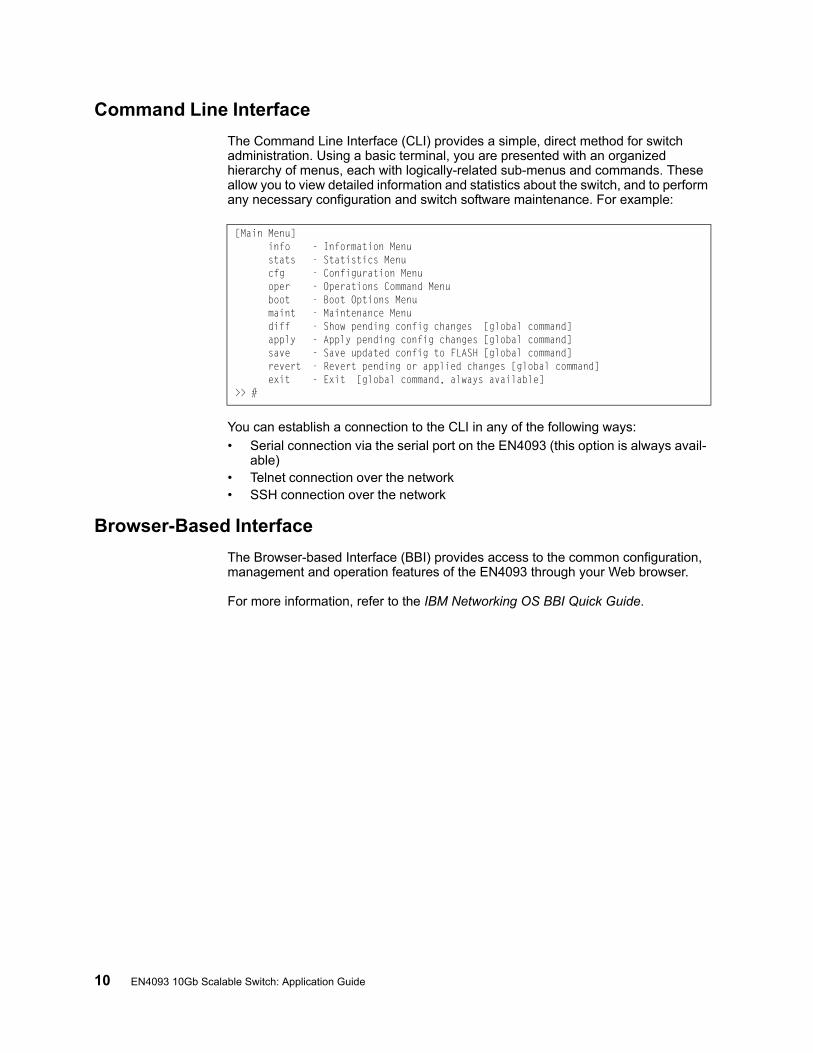
The Command Line Interface (CLI) provides a simple, direct method for switch administration. Using a basic terminal, you are presented with an organized hierarchy of menus, each with logically-related sub-menus and commands. These allow you to view detailed information and statistics about the switch, and to perform any necessary configuration and switch software maintenance. For example:
You can establish a connection to the CLI in any of the following ways:
• Serial connection via the serial port on the EN4093 (this option is always avail-able)
• Telnet connection over the network• SSH connection over the network
Browser-Based Interface
The Browser-based Interface (BBI) provides access to the common configuration, management and operation features of the EN4093 through your Web browser.
For more information, refer to the IBM Networking OS BBI Quick Guide.
[Main Menu] info - Information Menu stats - Statistics Menu cfg - Configuration Menu oper - Operations Command Menu boot - Boot Options Menu maint - Maintenance Menu diff - Show pending config changes [global command] apply - Apply pending config changes [global command] save - Save updated config to FLASH [global command] revert - Revert pending or applied changes [global command] exit - Exit [global command, always available]>> #

© Copyright IBM Corp. 2012 Chapter 1: Switch Administration 11
Establishing a Connection
The factory default settings permit initial switch administration through only the built-in serial port. All other forms of access require additional switch configuration before they can be used.
Remote access using the network requires the accessing terminal to have a valid, routable connection to the switch interface. The client IP address may be configured manually, or an IPv4 address can be provided automatically through the switch using a service such as DHCP or BOOTP relay (see “BOOTP/DHCP Client IP Address Services” on page 17), or an IPv6 address can be obtained using IPv6 stateless address configuration.
Note: Throughout this manual, IP address is used in places where either an IPv4 or IPv6 address is allowed. IPv4 addresses are entered in dotted-decimal notation (for example, 10.10.10.1), while IPv6 addresses are entered in hexadecimal notation (for example, 2001:db8:85a3::8a2e:370:7334). In places where only one type of address is allowed, IPv4 address or IPv6 address is specified.
Using the Chassis Management Module
The EN4093 is an integral subsystem within the overall IBM Flex System. The Flex System chassis includes a chassis management module (CMM) as the central element for overall chassis management and control.
The EN4093 uses port 66 (MGT1) to communicate with the chassis management module(s). Even when the EN4093 is in a factory default configuration, you can use the 1Gb Ethernet port on each CMM to configure and manage the EN4093.
For more information about using the chassis management module, see the IBM Flex System Fabric EN4093 10Gb Scalable Switch User Guide.
Factory-Default vs. CMM-Assigned IP Addresses
Each EN4093 must be assigned its own Internet Protocol version 4 (IPv4) address, which is used for communication with an SNMP network manager or other transmission control protocol/Internet Protocol (TCP/IP) applications (for example, BOOTP or TFTP). The factory-default IPv4 address is 10.90.90.x, where x is based on the number of the bay into which the EN4093 is installed. For additional information, see the User Guide. The chassis management module assigns an IPv4 address of 192.168.70.1xx, where xx is also based on the number of the bay into which each EN4093 is installed, as shown in the following table:
Note: EN4093s installed in Bay 1 and Bay 2 connect to server NICs 1 and 2, respectively.
Table 2. EN4093 IPv4 addresses, by switch-module bay numbers
Bay Number Factory-Default IPv4 Address IPv4 Address Assigned by CMM
Bay 1 10.90.90.91 192.168.70.120
Bay 2 10.90.90.92 192.168.70.121
Bay 3 10.90.90.93 192.168.70.122
Bay 4 10.90.90.94 192.168.70.123
12 EN4093 10Gb Scalable Switch: Application Guide
Using TelnetA Telnet connection offers the convenience of accessing the switch from a workstation connected to the network. Telnet access provides the same options for user and administrator access as those available through the console port.
By default, Telnet access is disabled. Use the following commands (available on the console only) to enable or disable Telnet access:
Once the switch is configured with an IP address and gateway, you can use Telnet to access switch administration from any workstation connected to the management network.
To establish a Telnet connection with the switch, run the Telnet program on your workstation and issue the following Telnet command:
You will then be prompted to enter a password as explained “Switch Login Levels” on page 18.
Using Secure Shell
Although a remote network administrator can manage the configuration of a EN4093 via Telnet, this method does not provide a secure connection. The Secure Shell (SSH) protocol enables you to securely log into another device over a network to execute commands remotely. As a secure alternative to using Telnet to manage switch configuration, SSH ensures that all data sent over the network is encrypted and secure.
The switch can do only one session of key/cipher generation at a time. Thus, a SSH/SCP client will not be able to login if the switch is doing key generation at that time. Similarly, the system will fail to do the key generation if a SSH/SCP client is logging in at that time.
The supported SSH encryption and authentication methods are listed below.
• Server Host Authentication: Client RSA-authenticates the switch when starting each connection
• Key Exchange: RSA
• Encryption: 3DES-CBC, DES
• User Authentication: Local password authentication, RADIUS, TACACS+
The following SSH clients have been tested:
• OpenSSH_5.1p1 Debian-3ubuntu1
• SecureCRT 5.0 (Van Dyke Technologies, Inc.)
• Putty beta 0.60
Note: The IBM Networking OS implementation of SSH supports both versions 1.5 and 2.0 and supports SSH client version 1.5 - 2.x.
>> # /cfg/sys/access/telnet ena|dis
telnet <switch IPv4 or IPv6 address>
© Copyright IBM Corp. 2012 Chapter 1: Switch Administration 13
Using SSH to Access the Switch
By default, the SSH feature is enabled. For information about enabling and using SSH for switch access, see “Secure Shell and Secure Copy” on page 34.
Once the IP parameters are configured and the SSH service is enabled, you can access the command line interface using an SSH connection.
To establish an SSH connection with the switch, run the SSH program on your workstation by issuing the SSH command, followed by the switch IPv4 or IPv6 address:
If SecurID authentication is required, use the following command:
You will then be prompted to enter a password as explained “Switch Login Levels” on page 18.
Using a Web Browser
The switch provides a Browser-Based Interface (BBI) for accessing the common configuration, management and operation features of the EN4093 through your Web browser.
You can access the BBI directly from an open Web browser window. Enter the URL using the IP address of the switch interface (for example, http://<IPv4 or IPv6 address>).
Configuring HTTP Access to the BBI
By default, BBI access via HTTP is disabled on the switch.
To enable or disable HTTP access to the switch BBI, use the following commands:
The default HTTP web server port to access the BBI is port 80. However, you can change the default Web server port with the following command:
To access the BBI from a workstation, open a Web browser window and type in the URL using the IP address of the switch interface (for example, http://<IPv4 or IPv6 address>).
# ssh <switch IP address>
# ssh -1 ace <switch IP address>
>> # /cfg/sys/access/http ena (Enable HTTP access)
-or-
>> # /cfg/sys/access/http dis (Disable HTTP access)
>> # /cfg/sys/access/wport <TCP port number>
14 EN4093 10Gb Scalable Switch: Application Guide
Configuring HTTPS Access to the BBI
The BBI can also be accessed via a secure HTTPS connection.
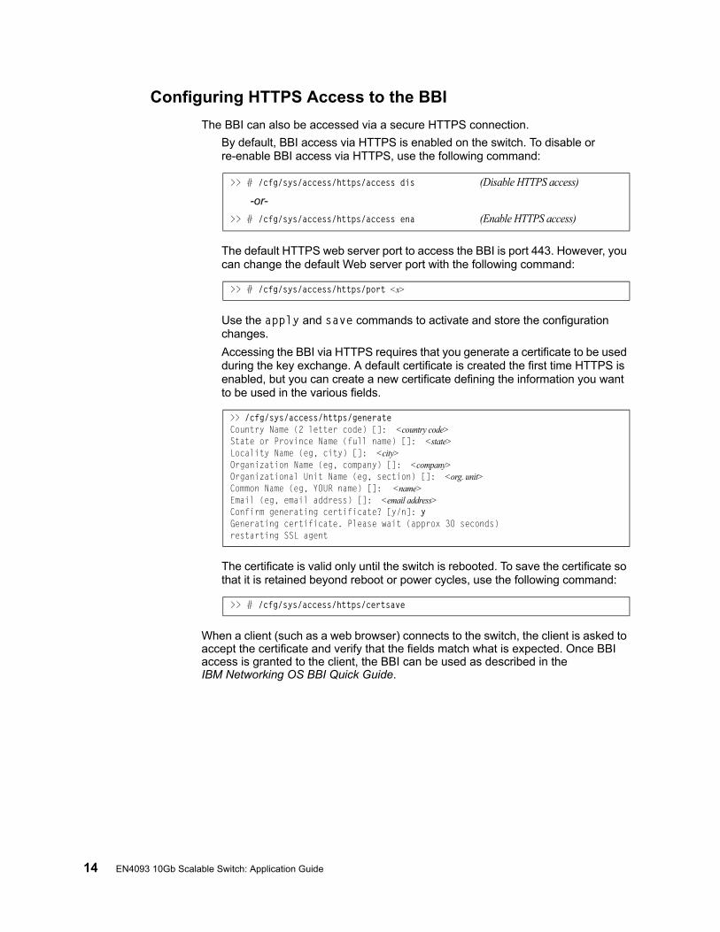
By default, BBI access via HTTPS is enabled on the switch. To disable or re-enable BBI access via HTTPS, use the following command:
The default HTTPS web server port to access the BBI is port 443. However, you can change the default Web server port with the following command:
Use the apply and save commands to activate and store the configuration changes.
Accessing the BBI via HTTPS requires that you generate a certificate to be used during the key exchange. A default certificate is created the first time HTTPS is enabled, but you can create a new certificate defining the information you want to be used in the various fields.
The certificate is valid only until the switch is rebooted. To save the certificate so that it is retained beyond reboot or power cycles, use the following command:
When a client (such as a web browser) connects to the switch, the client is asked to accept the certificate and verify that the fields match what is expected. Once BBI access is granted to the client, the BBI can be used as described in the IBM Networking OS BBI Quick Guide.
>> # /cfg/sys/access/https/access dis (Disable HTTPS access)
-or-
>> # /cfg/sys/access/https/access ena (Enable HTTPS access)
>> # /cfg/sys/access/https/port <x>
>> /cfg/sys/access/https/generateCountry Name (2 letter code) []: <country code>State or Province Name (full name) []: <state>Locality Name (eg, city) []: <city>Organization Name (eg, company) []: <company>Organizational Unit Name (eg, section) []: <org. unit>Common Name (eg, YOUR name) []: <name>Email (eg, email address) []: <email address>Confirm generating certificate? [y/n]: yGenerating certificate. Please wait (approx 30 seconds)restarting SSL agent
>> # /cfg/sys/access/https/certsave
© Copyright IBM Corp. 2012 Chapter 1: Switch Administration 15
BBI Summary
The BBI is organized at a high level as follows:
Context buttons—These buttons allow you to select the type of action you wish to perform. The Configuration button provides access to the configuration elements for the entire switch. The Statistics button provides access to the switch statistics and state information. The Dashboard button allows you to display the settings and operating status of a variety of switch features.
Navigation Window—This window provides a menu list of switch features and functions:
• System—this folder provides access to the configuration elements for the entire switch.
• Switch Ports—Configure each of the physical ports on the switch.
• Port-Based Port Mirroring—Configure port mirroring behavior.
• Layer 2—Configure Layer 2 features for the switch.
• RMON Menu—Configure Remote Monitoring features for the switch.
• Layer 3—Configure Layer 3 features for the switch.
• QoS—Configure Quality of Service features for the switch.
• Access Control—Configure Access Control Lists to filter IP packets.
• Virtualization – Configure VMready for virtual machine (VM) support.
For information on using the BBI, refer to the IBM Networking OS BBI Quick Guide.
16 EN4093 10Gb Scalable Switch: Application Guide
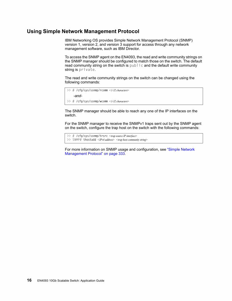
Using Simple Network Management Protocol
IBM Networking OS provides Simple Network Management Protocol (SNMP) version 1, version 2, and version 3 support for access through any network management software, such as IBM Director.
To access the SNMP agent on the EN4093, the read and write community strings on the SNMP manager should be configured to match those on the switch. The default read community string on the switch is public and the default write community string is private.
The read and write community strings on the switch can be changed using the following commands:
The SNMP manager should be able to reach any one of the IP interfaces on the switch.
For the SNMP manager to receive the SNMPv1 traps sent out by the SNMP agent on the switch, configure the trap host on the switch with the following commands:
For more information on SNMP usage and configuration, see “Simple Network Management Protocol” on page 333.
>> # /cfg/sys/ssnmp/rcomm <1-32 characters>
-and->> # /cfg/sys/ssnmp/wcomm <1-32 characters>
>> # /cfg/sys/ssnmp/trsrc <trap source IP interface>>> SNMP# thostadd <IPv4 address> <trap host community string>

© Copyright IBM Corp. 2012 Chapter 1: Switch Administration 17
BOOTP/DHCP Client IP Address Services
For remote switch administration, the client terminal device must have a valid IP address on the same network as a switch interface. The IP address on the client device may be configured manually, or obtained automatically using IPv6 stateless address configuration, or an IPv4 address may obtained automatically via BOOTP or DHCP relay as discussed below.
The EN4093 can function as a relay agent for Bootstrap Protocol (BOOTP) or DHCP. This allows clients to be assigned an IPv4 address for a finite lease period, reassigning freed addresses later to other clients.
Acting as a relay agent, the switch can forward a client’s IPv4 address request to up to four BOOTP/DHCP servers. In addition to the four global BOOTP/DHCP servers, up to four domain-specific BOOTP/DHCP servers can be configured for each of up to 10 VLANs.
When a switch receives a BOOTP/DHCP request from a client seeking an IPv4 address, the switch acts as a proxy for the client. The request is forwarded as a UDP Unicast MAC layer message to the BOOTP/DHCP servers configured for the client’s VLAN, or to the global BOOTP/DHCP servers if no domain-specific BOOTP/DHCP servers are configured for the client’s VLAN. The servers respond to the switch with a Unicast reply that contains the IPv4 default gateway and the IPv4 address for the client. The switch then forwards this reply back to the client.
DHCP is described in RFC 2131, and the DHCP relay agent supported on the EN4093 is described in RFC 1542. DHCP uses UDP as its transport protocol. The client sends messages to the server on port 67 and the server sends messages to the client on port 68.
BOOTP and DHCP relay are collectively configured using the BOOTP commands and menus on the EN4093.
18 EN4093 10Gb Scalable Switch: Application Guide
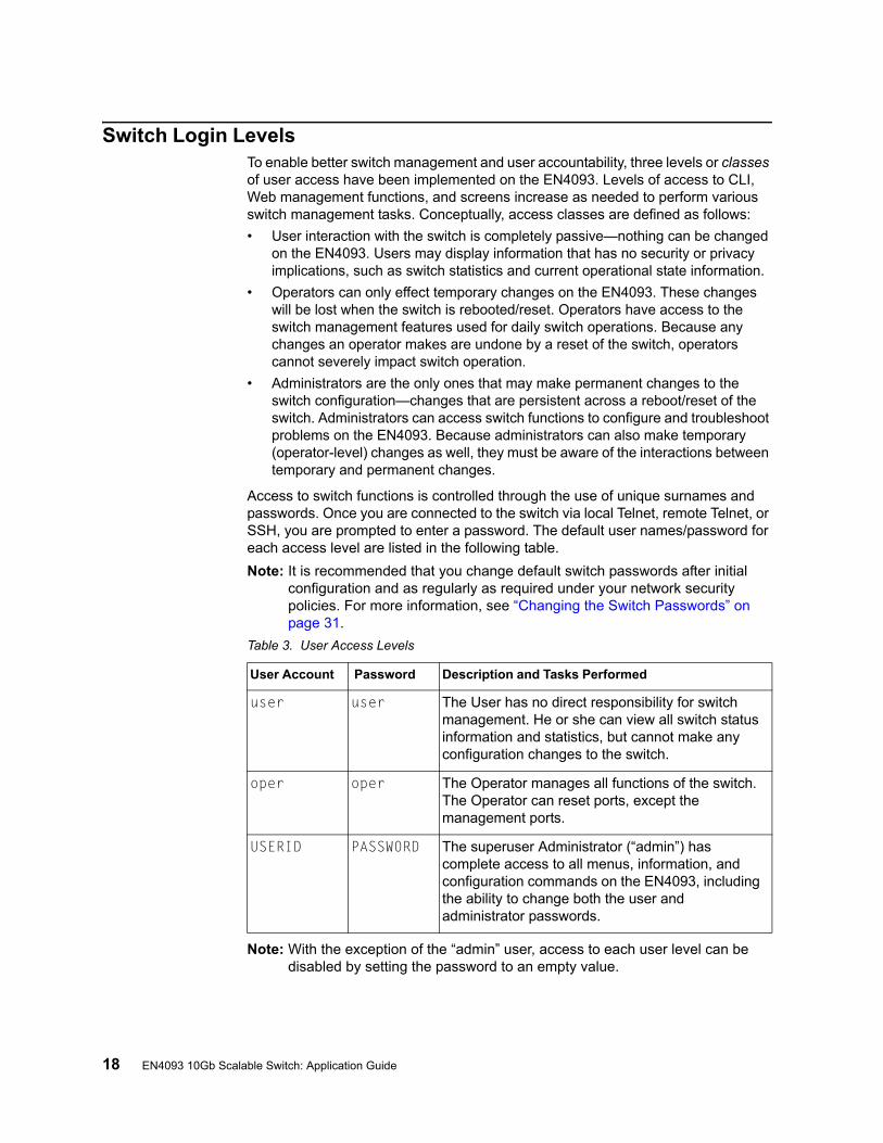
Switch Login LevelsTo enable better switch management and user accountability, three levels or classes of user access have been implemented on the EN4093. Levels of access to CLI, Web management functions, and screens increase as needed to perform various switch management tasks. Conceptually, access classes are defined as follows:
• User interaction with the switch is completely passive—nothing can be changed on the EN4093. Users may display information that has no security or privacy implications, such as switch statistics and current operational state information.
• Operators can only effect temporary changes on the EN4093. These changes will be lost when the switch is rebooted/reset. Operators have access to the switch management features used for daily switch operations. Because any changes an operator makes are undone by a reset of the switch, operators cannot severely impact switch operation.
• Administrators are the only ones that may make permanent changes to the switch configuration—changes that are persistent across a reboot/reset of the switch. Administrators can access switch functions to configure and troubleshoot problems on the EN4093. Because administrators can also make temporary (operator-level) changes as well, they must be aware of the interactions between temporary and permanent changes.
Access to switch functions is controlled through the use of unique surnames and passwords. Once you are connected to the switch via local Telnet, remote Telnet, or SSH, you are prompted to enter a password. The default user names/password for each access level are listed in the following table.
Note: It is recommended that you change default switch passwords after initial configuration and as regularly as required under your network security policies. For more information, see “Changing the Switch Passwords” on page 31.
Note: With the exception of the “admin” user, access to each user level can be disabled by setting the password to an empty value.
Table 3. User Access Levels
User Account Password Description and Tasks Performed
user user The User has no direct responsibility for switch management. He or she can view all switch status information and statistics, but cannot make any configuration changes to the switch.
oper oper The Operator manages all functions of the switch. The Operator can reset ports, except the management ports.
USERID PASSW0RD The superuser Administrator (“admin”) has complete access to all menus, information, and configuration commands on the EN4093, including the ability to change both the user and administrator passwords.
© Copyright IBM Corp. 2012 19
Chapter 2. Initial Setup
To help with the initial process of configuring your switch, the IBM Networking OS software includes a Setup utility. The Setup utility prompts you step-by-step to enter all the necessary information for basic configuration of the switch.
Setup can be activated manually from the command line interface any time after login: /cfg/setup
Information Needed for Setup
Setup requests the following information:
• Basic system information– Date & time
– Whether to use Spanning Tree Group or not
• Optional configuration for each port– Speed, duplex, flow control, and negotiation mode (as appropriate)
– Whether to use VLAN tagging or not (as appropriate)
• Optional configuration for each VLAN– Name of VLAN
– Which ports are included in the VLAN
• Optional configuration of IP parameters– IP address/mask and VLAN for each IP interface
– IP addresses for default gateway
– Whether IP forwarding is enabled or not
20 EN4093 10Gb Scalable Switch: Application Guide
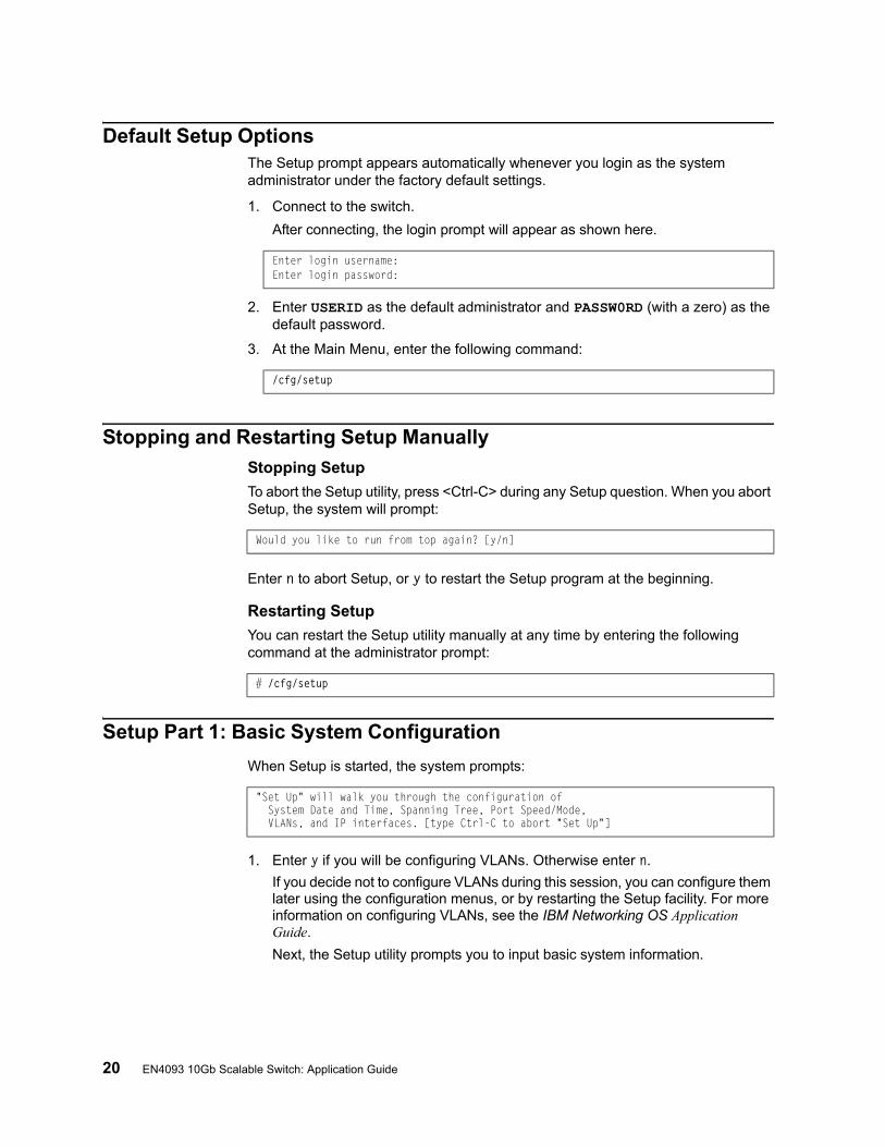
Default Setup OptionsThe Setup prompt appears automatically whenever you login as the system administrator under the factory default settings.
1. Connect to the switch.
After connecting, the login prompt will appear as shown here.
2. Enter USERID as the default administrator and PASSW0RD (with a zero) as the default password.
3. At the Main Menu, enter the following command:
Stopping and Restarting Setup Manually
Stopping Setup
To abort the Setup utility, press <Ctrl-C> during any Setup question. When you abort Setup, the system will prompt:
Enter n to abort Setup, or y to restart the Setup program at the beginning.
Restarting Setup
You can restart the Setup utility manually at any time by entering the following command at the administrator prompt:
Setup Part 1: Basic System Configuration
When Setup is started, the system prompts:
1. Enter y if you will be configuring VLANs. Otherwise enter n.
If you decide not to configure VLANs during this session, you can configure them later using the configuration menus, or by restarting the Setup facility. For more information on configuring VLANs, see the IBM Networking OS Application Guide.
Next, the Setup utility prompts you to input basic system information.
Enter login username: Enter login password:
/cfg/setup
Would you like to run from top again? [y/n]
# /cfg/setup
"Set Up" will walk you through the configuration of System Date and Time, Spanning Tree, Port Speed/Mode, VLANs, and IP interfaces. [type Ctrl-C to abort "Set Up"]

© Copyright IBM Corp. 2012 Chapter 2: Initial Setup 21
2. Enter the year of the current date at the prompt:
Enter the four-digits that represent the year. To keep the current year, press <Enter>.
3. Enter the month of the current system date at the prompt:
Enter the month as a number from 1 to 12. To keep the current month, press <Enter>.
4. Enter the day of the current date at the prompt:
Enter the date as a number from 1 to 31. To keep the current day, press <Enter>.
The system displays the date and time settings:
5. Enter the hour of the current system time at the prompt:
Enter the hour as a number from 00 to 23. To keep the current hour, press <Enter>.
6. Enter the minute of the current time at the prompt:
Enter the minute as a number from 00 to 59. To keep the current minute, press <Enter>.
7. Enter the seconds of the current time at the prompt:
Enter the seconds as a number from 00 to 59. To keep the current second, press <Enter>. The system then displays the date and time settings:
System Date:Enter year [2012]:
System Date:Enter month [1]:
Enter day [3]:
System clock set to 18:55:36 Wed Jan 28, 2012.
System Time:Enter hour in 24-hour format [18]:
Enter minutes [55]:
Enter seconds [37]:
System clock set to 8:55:36 Wed Jan 28, 2012.
22 EN4093 10Gb Scalable Switch: Application Guide
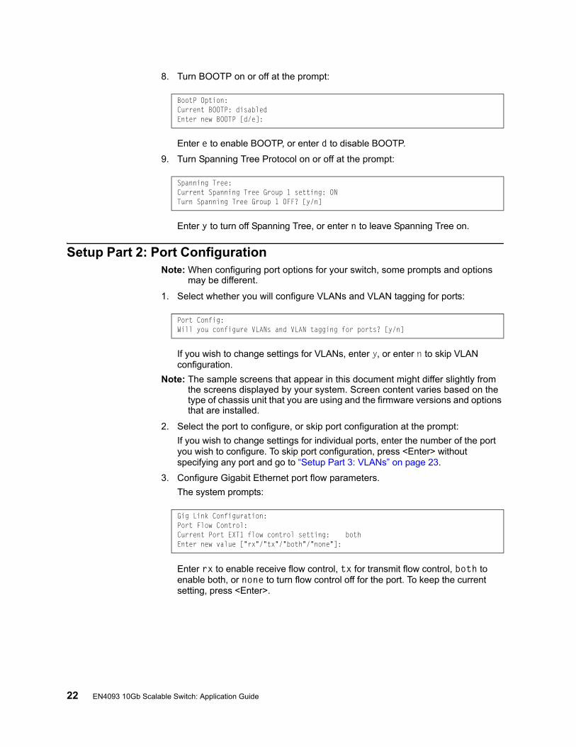
8. Turn BOOTP on or off at the prompt:
Enter e to enable BOOTP, or enter d to disable BOOTP.
9. Turn Spanning Tree Protocol on or off at the prompt:
Enter y to turn off Spanning Tree, or enter n to leave Spanning Tree on.
Setup Part 2: Port ConfigurationNote: When configuring port options for your switch, some prompts and options
may be different.
1. Select whether you will configure VLANs and VLAN tagging for ports:
If you wish to change settings for VLANs, enter y, or enter n to skip VLAN configuration.
Note: The sample screens that appear in this document might differ slightly from the screens displayed by your system. Screen content varies based on the type of chassis unit that you are using and the firmware versions and options that are installed.
2. Select the port to configure, or skip port configuration at the prompt:
If you wish to change settings for individual ports, enter the number of the port you wish to configure. To skip port configuration, press <Enter> without specifying any port and go to “Setup Part 3: VLANs” on page 23.
3. Configure Gigabit Ethernet port flow parameters.
The system prompts:
Enter rx to enable receive flow control, tx for transmit flow control, both to enable both, or none to turn flow control off for the port. To keep the current setting, press <Enter>.
BootP Option:Current BOOTP: disabledEnter new BOOTP [d/e]:
Spanning Tree:Current Spanning Tree Group 1 setting: ONTurn Spanning Tree Group 1 OFF? [y/n]
Port Config:Will you configure VLANs and VLAN tagging for ports? [y/n]
Gig Link Configuration:Port Flow Control:Current Port EXT1 flow control setting: bothEnter new value ["rx"/"tx"/"both"/"none"]:
© Copyright IBM Corp. 2012 Chapter 2: Initial Setup 23
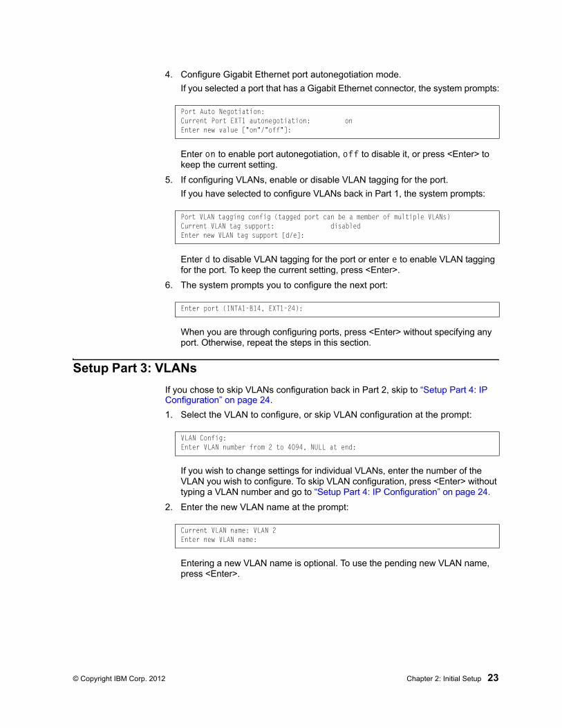
4. Configure Gigabit Ethernet port autonegotiation mode.
If you selected a port that has a Gigabit Ethernet connector, the system prompts:
Enter on to enable port autonegotiation, off to disable it, or press <Enter> to keep the current setting.
5. If configuring VLANs, enable or disable VLAN tagging for the port.
If you have selected to configure VLANs back in Part 1, the system prompts:
Enter d to disable VLAN tagging for the port or enter e to enable VLAN tagging for the port. To keep the current setting, press <Enter>.
6. The system prompts you to configure the next port:
When you are through configuring ports, press <Enter> without specifying any port. Otherwise, repeat the steps in this section.
Setup Part 3: VLANs
If you chose to skip VLANs configuration back in Part 2, skip to “Setup Part 4: IP Configuration” on page 24.
1. Select the VLAN to configure, or skip VLAN configuration at the prompt:
If you wish to change settings for individual VLANs, enter the number of the VLAN you wish to configure. To skip VLAN configuration, press <Enter> without typing a VLAN number and go to “Setup Part 4: IP Configuration” on page 24.
2. Enter the new VLAN name at the prompt:
Entering a new VLAN name is optional. To use the pending new VLAN name, press <Enter>.
Port Auto Negotiation:Current Port EXT1 autonegotiation: onEnter new value ["on"/"off"]:
Port VLAN tagging config (tagged port can be a member of multiple VLANs)Current VLAN tag support: disabledEnter new VLAN tag support [d/e]:
Enter port (INTA1-B14, EXT1-24):
VLAN Config:Enter VLAN number from 2 to 4094, NULL at end:
Current VLAN name: VLAN 2Enter new VLAN name:
24 EN4093 10Gb Scalable Switch: Application Guide
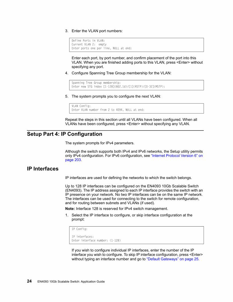
3. Enter the VLAN port numbers:
Enter each port, by port number, and confirm placement of the port into this VLAN. When you are finished adding ports to this VLAN, press <Enter> without specifying any port.
4. Configure Spanning Tree Group membership for the VLAN:
5. The system prompts you to configure the next VLAN:
Repeat the steps in this section until all VLANs have been configured. When all VLANs have been configured, press <Enter> without specifying any VLAN.
Setup Part 4: IP Configuration
The system prompts for IPv4 parameters.
Although the switch supports both IPv4 and IPv6 networks, the Setup utility permits only IPv4 configuration. For IPv6 configuration, see “Internet Protocol Version 6” on page 203.
IP Interfaces
IP interfaces are used for defining the networks to which the switch belongs.
Up to 128 IP interfaces can be configured on the EN4093 10Gb Scalable Switch (EN4093). The IP address assigned to each IP interface provides the switch with an IP presence on your network. No two IP interfaces can be on the same IP network. The interfaces can be used for connecting to the switch for remote configuration, and for routing between subnets and VLANs (if used).
Note: Interface 128 is reserved for IPv4 switch management.
1. Select the IP interface to configure, or skip interface configuration at the prompt:
If you wish to configure individual IP interfaces, enter the number of the IP interface you wish to configure. To skip IP interface configuration, press <Enter> without typing an interface number and go to “Default Gateways” on page 25.
Define Ports in VLAN:Current VLAN 2: emptyEnter ports one per line, NULL at end:
Spanning Tree Group membership:Enter new STG index [1-128](802.1d)/[1](RSTP)/[0-32](MSTP):
VLAN Config:Enter VLAN number from 2 to 4094, NULL at end:
IP Config:
IP interfaces:Enter interface number: (1-128)
© Copyright IBM Corp. 2012 Chapter 2: Initial Setup 25
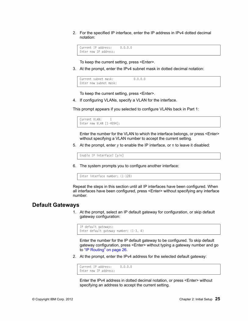
2. For the specified IP interface, enter the IP address in IPv4 dotted decimal notation:
To keep the current setting, press <Enter>.
3. At the prompt, enter the IPv4 subnet mask in dotted decimal notation:
To keep the current setting, press <Enter>.
4. If configuring VLANs, specify a VLAN for the interface.
This prompt appears if you selected to configure VLANs back in Part 1:
Enter the number for the VLAN to which the interface belongs, or press <Enter> without specifying a VLAN number to accept the current setting.
5. At the prompt, enter y to enable the IP interface, or n to leave it disabled:
6. The system prompts you to configure another interface:
Repeat the steps in this section until all IP interfaces have been configured. When all interfaces have been configured, press <Enter> without specifying any interface number.
Default Gateways1. At the prompt, select an IP default gateway for configuration, or skip default
gateway configuration:
Enter the number for the IP default gateway to be configured. To skip default gateway configuration, press <Enter> without typing a gateway number and go to “IP Routing” on page 26.
2. At the prompt, enter the IPv4 address for the selected default gateway:
Enter the IPv4 address in dotted decimal notation, or press <Enter> without specifying an address to accept the current setting.
Current IP address: 0.0.0.0Enter new IP address:
Current subnet mask: 0.0.0.0Enter new subnet mask:
Current VLAN: 1Enter new VLAN [1-4094]:
Enable IP interface? [y/n]
Enter interface number: (1-128)
IP default gateways:Enter default gateway number: (1-3, 4)
Current IP address: 0.0.0.0Enter new IP address:
26 EN4093 10Gb Scalable Switch: Application Guide
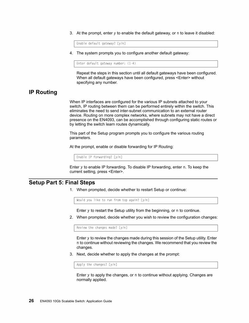
3. At the prompt, enter y to enable the default gateway, or n to leave it disabled:
4. The system prompts you to configure another default gateway:
Repeat the steps in this section until all default gateways have been configured. When all default gateways have been configured, press <Enter> without specifying any number.
IP Routing
When IP interfaces are configured for the various IP subnets attached to your switch, IP routing between them can be performed entirely within the switch. This eliminates the need to send inter-subnet communication to an external router device. Routing on more complex networks, where subnets may not have a direct presence on the EN4093, can be accomplished through configuring static routes or by letting the switch learn routes dynamically.
This part of the Setup program prompts you to configure the various routing parameters.
At the prompt, enable or disable forwarding for IP Routing:
Enter y to enable IP forwarding. To disable IP forwarding, enter n. To keep the current setting, press <Enter>.
Setup Part 5: Final Steps1. When prompted, decide whether to restart Setup or continue:
Enter y to restart the Setup utility from the beginning, or n to continue.
2. When prompted, decide whether you wish to review the configuration changes:
Enter y to review the changes made during this session of the Setup utility. Enter n to continue without reviewing the changes. We recommend that you review the changes.
3. Next, decide whether to apply the changes at the prompt:
Enter y to apply the changes, or n to continue without applying. Changes are normally applied.
Enable default gateway? [y/n]
Enter default gateway number: (1-4)
Enable IP forwarding? [y/n]
Would you like to run from top again? [y/n]
Review the changes made? [y/n]
Apply the changes? [y/n]
© Copyright IBM Corp. 2012 Chapter 2: Initial Setup 27
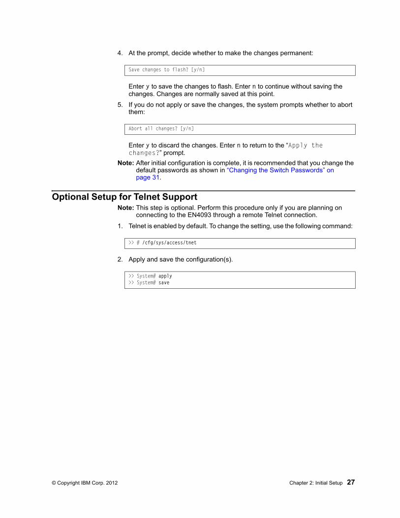
4. At the prompt, decide whether to make the changes permanent:
Enter y to save the changes to flash. Enter n to continue without saving the changes. Changes are normally saved at this point.
5. If you do not apply or save the changes, the system prompts whether to abort them:
Enter y to discard the changes. Enter n to return to the “Apply the changes?” prompt.
Note: After initial configuration is complete, it is recommended that you change the default passwords as shown in “Changing the Switch Passwords” on page 31.
Optional Setup for Telnet SupportNote: This step is optional. Perform this procedure only if you are planning on
connecting to the EN4093 through a remote Telnet connection.
1. Telnet is enabled by default. To change the setting, use the following command:
2. Apply and save the configuration(s).
Save changes to flash? [y/n]
Abort all changes? [y/n]
>> # /cfg/sys/access/tnet
>> System# apply>> System# save

28 EN4093 10Gb Scalable Switch: Application Guide

© Copyright IBM Corp. 2012 29
Part 2: Securing the Switch

30 EN4093 10Gb Scalable Switch: Application Guide
© Copyright IBM Corp. 2012 31
Chapter 3. Securing Administration
This chapter discusses different methods of securing local and remote administration on the EN4093 10Gb Scalable Switch (EN4093):
• “Changing the Switch Passwords” on page 31
• “Secure Shell and Secure Copy” on page 34
• “End User Access Control” on page 40
• “Protected Mode” on page 43
Changing the Switch Passwords
It is recommended that you change the administrator and user passwords after initial configuration and as regularly as required under your network security policies.
To change the administrator password, you must login using the administrator password.
Note: If you forget your administrator password, call your technical support representative for help using the password fix-up mode.
Changing the Default Administrator Password
The administrator has complete access to all menus, information, and configuration commands, including the ability to change both the user and administrator passwords.
The default administrator account is USERID. The default password for the administrator account is PASSW0RD (with a zero). To change the administrator password, use the following procedure:
1. Connect to the switch and log in as the administrator.
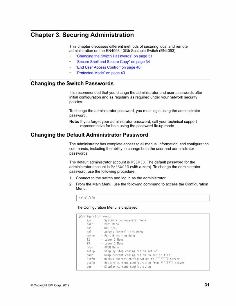
2. From the Main Menu, use the following command to access the Configuration Menu:
The Configuration Menu is displayed.
Main# /cfg
[Configuration Menu] sys - System-wide Parameter Menu port - Port Menu qos - QOS Menu acl - Access Control List Menu pmirr - Port Mirroring Menu l2 - Layer 2 Menu l3 - Layer 3 Menu rmon - RMON Menu setup - Step by step configuration set up dump - Dump current configuration to script file ptcfg - Backup current configuration to FTP/TFTP server gtcfg - Restore current configuration from FTP/TFTP server cur - Display current configuration
32 EN4093 10Gb Scalable Switch: Application Guide
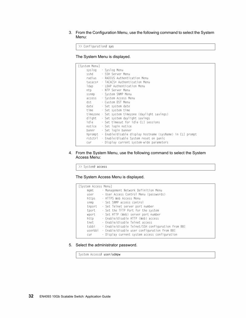
3. From the Configuration Menu, use the following command to select the System Menu:
The System Menu is displayed.
4. From the System Menu, use the following command to select the System Access Menu:
The System Access Menu is displayed.
5. Select the administrator password.
>> Configuration# sys
[System Menu] syslog - Syslog Menu sshd - SSH Server Menu radius - RADIUS Authentication Menu tacacs+ - TACACS+ Authentication Menu ldap - LDAP Authentication Menu ntp - NTP Server Menu ssnmp - System SNMP Menu access - System Access Menu dst - Custom DST Menu date - Set system date time - Set system time timezone - Set system timezone (daylight savings) dlight - Set system daylight savings idle - Set timeout for idle CLI sessions notice - Set login notice bannr - Set login banner hprompt - Enable/disable display hostname (sysName) in CLI prompt rstctrl - Enable/disable System reset on panic cur - Display current system-wide parameters
>> System# access
[System Access Menu] mgmt - Management Network Definition Menu user - User Access Control Menu (passwords) https - HTTPS Web Access Menu snmp - Set SNMP access control tnport - Set Telnet server port number tport - Set the TFTP Port for the system wport - Set HTTP (Web) server port number http - Enable/disable HTTP (Web) access tnet - Enable/disable Telnet access tsbbi - Enable/disable Telnet/SSH configuration from BBI userbbi - Enable/disable user configuration from BBI cur - Display current system access configuration
System Access# user/admpw
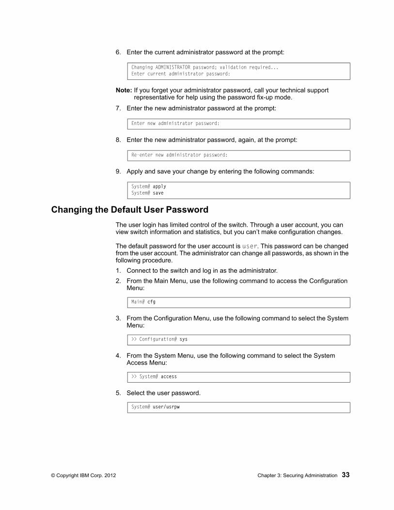
© Copyright IBM Corp. 2012 Chapter 3: Securing Administration 33
6. Enter the current administrator password at the prompt:
Note: If you forget your administrator password, call your technical support representative for help using the password fix-up mode.
7. Enter the new administrator password at the prompt:
8. Enter the new administrator password, again, at the prompt:
9. Apply and save your change by entering the following commands:
Changing the Default User Password
The user login has limited control of the switch. Through a user account, you can view switch information and statistics, but you can’t make configuration changes.
The default password for the user account is user. This password can be changed from the user account. The administrator can change all passwords, as shown in the following procedure.
1. Connect to the switch and log in as the administrator.
2. From the Main Menu, use the following command to access the Configuration Menu:
3. From the Configuration Menu, use the following command to select the System Menu:
4. From the System Menu, use the following command to select the System Access Menu:
5. Select the user password.
Changing ADMINISTRATOR password; validation required...Enter current administrator password:
Enter new administrator password:
Re-enter new administrator password:
System# applySystem# save
Main# cfg
>> Configuration# sys
>> System# access
System# user/usrpw
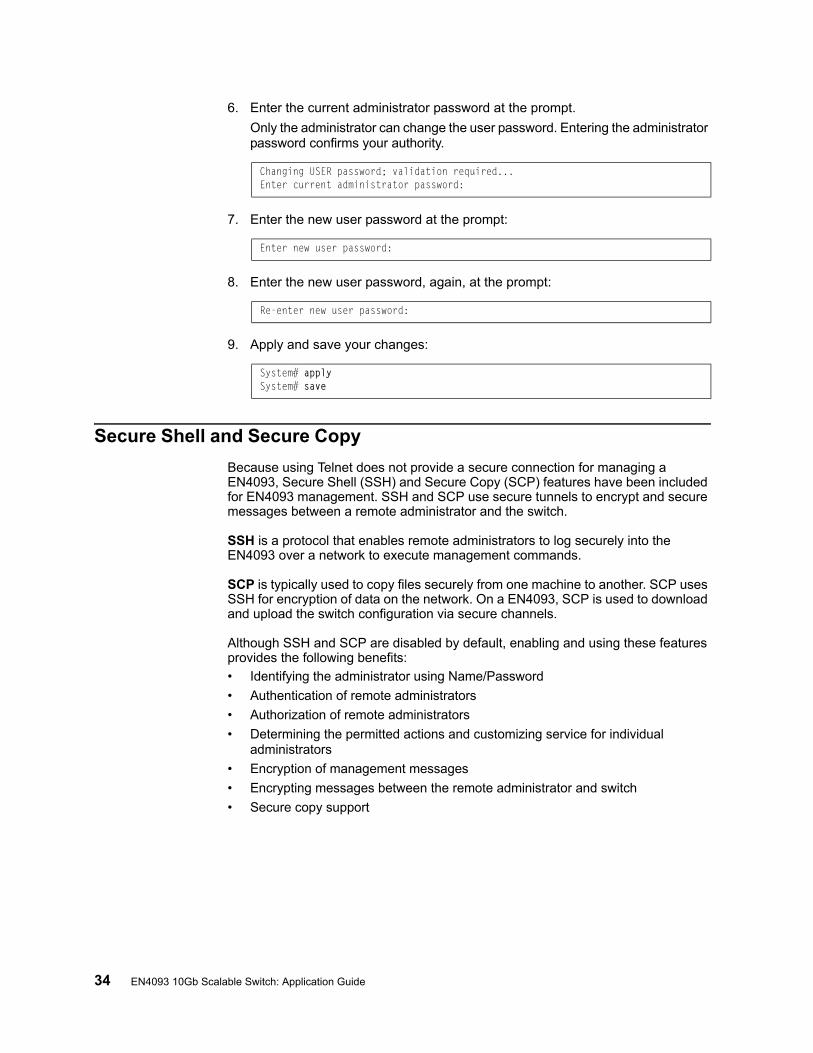
34 EN4093 10Gb Scalable Switch: Application Guide
6. Enter the current administrator password at the prompt.
Only the administrator can change the user password. Entering the administrator password confirms your authority.
7. Enter the new user password at the prompt:
8. Enter the new user password, again, at the prompt:
9. Apply and save your changes:
Secure Shell and Secure Copy
Because using Telnet does not provide a secure connection for managing a EN4093, Secure Shell (SSH) and Secure Copy (SCP) features have been included for EN4093 management. SSH and SCP use secure tunnels to encrypt and secure messages between a remote administrator and the switch.
SSH is a protocol that enables remote administrators to log securely into the EN4093 over a network to execute management commands.
SCP is typically used to copy files securely from one machine to another. SCP uses SSH for encryption of data on the network. On a EN4093, SCP is used to download and upload the switch configuration via secure channels.
Although SSH and SCP are disabled by default, enabling and using these features provides the following benefits:
• Identifying the administrator using Name/Password
• Authentication of remote administrators
• Authorization of remote administrators
• Determining the permitted actions and customizing service for individual administrators
• Encryption of management messages
• Encrypting messages between the remote administrator and switch
• Secure copy support
Changing USER password; validation required...Enter current administrator password:
Enter new user password:
Re-enter new user password:
System# applySystem# save
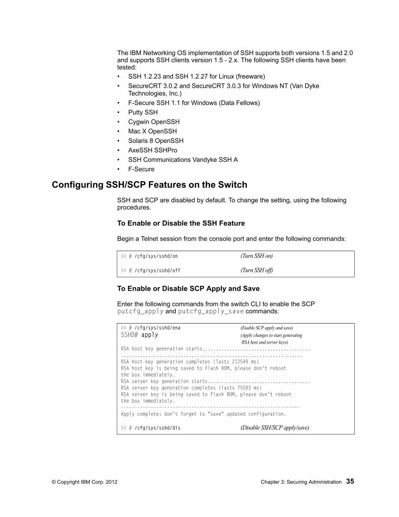
© Copyright IBM Corp. 2012 Chapter 3: Securing Administration 35
The IBM Networking OS implementation of SSH supports both versions 1.5 and 2.0 and supports SSH clients version 1.5 - 2.x. The following SSH clients have been tested:
• SSH 1.2.23 and SSH 1.2.27 for Linux (freeware)
• SecureCRT 3.0.2 and SecureCRT 3.0.3 for Windows NT (Van Dyke Technologies, Inc.)
• F-Secure SSH 1.1 for Windows (Data Fellows)
• Putty SSH
• Cygwin OpenSSH
• Mac X OpenSSH
• Solaris 8 OpenSSH
• AxeSSH SSHPro
• SSH Communications Vandyke SSH A
• F-Secure
Configuring SSH/SCP Features on the Switch
SSH and SCP are disabled by default. To change the setting, using the following procedures.
To Enable or Disable the SSH Feature
Begin a Telnet session from the console port and enter the following commands:
To Enable or Disable SCP Apply and Save
Enter the following commands from the switch CLI to enable the SCP putcfg_apply and putcfg_apply_save commands:
>> # /cfg/sys/sshd/on (Turn SSH on)
>> # /cfg/sys/sshd/off (Turn SSH off)
>> # /cfg/sys/sshd/ena (Enable SCP apply and save)
SSHD# apply (Apply changes to start generating RSA host and server keys)
RSA host key generation starts...........................................................................................................RSA host key generation completes (lasts 212549 ms)RSA host key is being saved to Flash ROM, please don't rebootthe box immediately.RSA server key generation starts......................................RSA server key generation completes (lasts 75503 ms)RSA server key is being saved to Flash ROM, please don't rebootthe box immediately.------------------------------------------------------------------Apply complete; don't forget to "save" updated configuration.
>> # /cfg/sys/sshd/dis (Disable SSH/SCP apply/save)
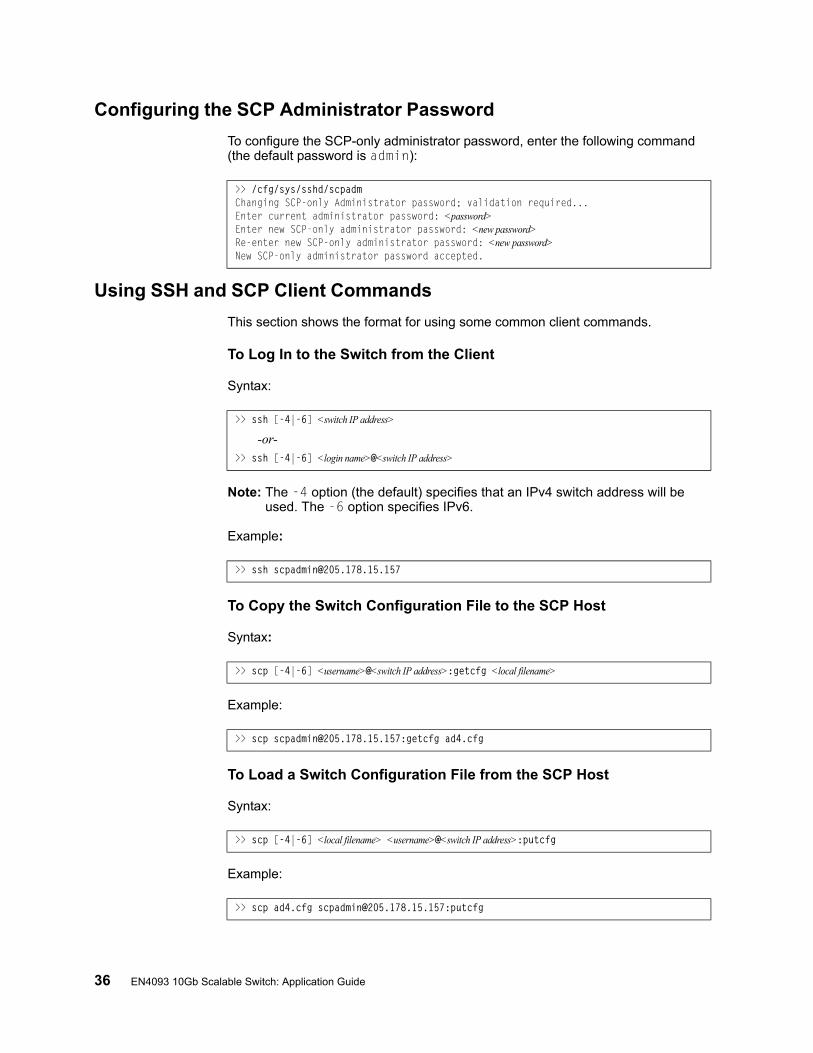
36 EN4093 10Gb Scalable Switch: Application Guide
Configuring the SCP Administrator Password
To configure the SCP-only administrator password, enter the following command (the default password is admin):
Using SSH and SCP Client Commands
This section shows the format for using some common client commands.
To Log In to the Switch from the Client
Syntax:
Note: The -4 option (the default) specifies that an IPv4 switch address will be used. The -6 option specifies IPv6.
Example:
To Copy the Switch Configuration File to the SCP Host
Syntax:
Example:
To Load a Switch Configuration File from the SCP Host
Syntax:
Example:
>> /cfg/sys/sshd/scpadmChanging SCP-only Administrator password; validation required...Enter current administrator password: <password>Enter new SCP-only administrator password: <new password>Re-enter new SCP-only administrator password: <new password>New SCP-only administrator password accepted.
>> ssh [-4|-6] <switch IP address>
-or->> ssh [-4|-6] <login name>@<switch IP address>
>> ssh [email protected]
>> scp [-4|-6] <username>@<switch IP address>:getcfg <local filename>
>> scp [email protected]:getcfg ad4.cfg
>> scp [-4|-6] <local filename> <username>@<switch IP address>:putcfg
>> scp ad4.cfg [email protected]:putcfg
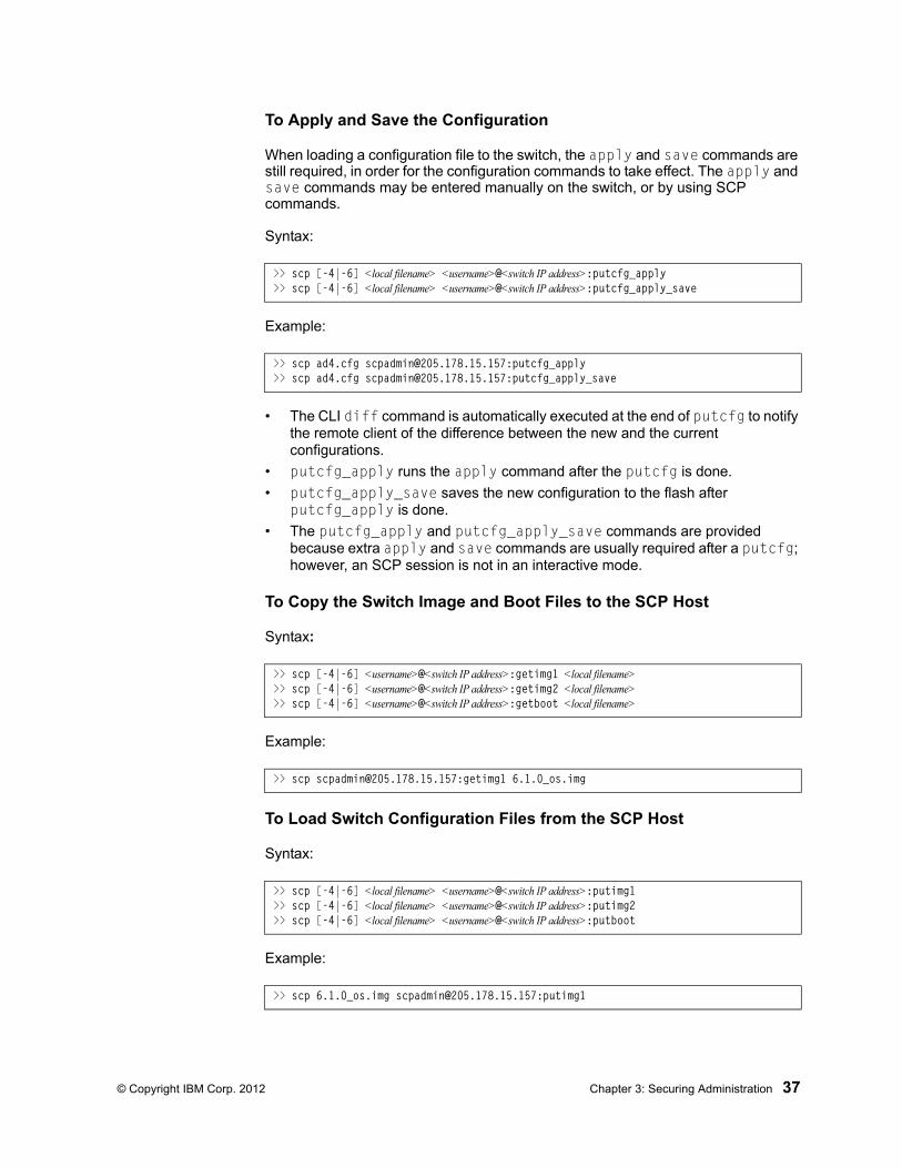
© Copyright IBM Corp. 2012 Chapter 3: Securing Administration 37
To Apply and Save the Configuration
When loading a configuration file to the switch, the apply and save commands are still required, in order for the configuration commands to take effect. The apply and save commands may be entered manually on the switch, or by using SCP commands.
Syntax:
Example:
• The CLI diff command is automatically executed at the end of putcfg to notify the remote client of the difference between the new and the current configurations.
• putcfg_apply runs the apply command after the putcfg is done.
• putcfg_apply_save saves the new configuration to the flash after putcfg_apply is done.
• The putcfg_apply and putcfg_apply_save commands are provided because extra apply and save commands are usually required after a putcfg; however, an SCP session is not in an interactive mode.
To Copy the Switch Image and Boot Files to the SCP Host
Syntax:
Example:
To Load Switch Configuration Files from the SCP Host
Syntax:
Example:
>> scp [-4|-6] <local filename> <username>@<switch IP address>:putcfg_apply>> scp [-4|-6] <local filename> <username>@<switch IP address>:putcfg_apply_save
>> scp ad4.cfg [email protected]:putcfg_apply>> scp ad4.cfg [email protected]:putcfg_apply_save
>> scp [-4|-6] <username>@<switch IP address>:getimg1 <local filename> >> scp [-4|-6] <username>@<switch IP address>:getimg2 <local filename> >> scp [-4|-6] <username>@<switch IP address>:getboot <local filename>
>> scp [email protected]:getimg1 6.1.0_os.img
>> scp [-4|-6] <local filename> <username>@<switch IP address>:putimg1>> scp [-4|-6] <local filename> <username>@<switch IP address>:putimg2>> scp [-4|-6] <local filename> <username>@<switch IP address>:putboot
>> scp 6.1.0_os.img [email protected]:putimg1
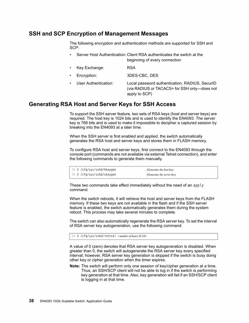
38 EN4093 10Gb Scalable Switch: Application Guide
SSH and SCP Encryption of Management Messages
The following encryption and authentication methods are supported for SSH and SCP:
• Server Host Authentication: Client RSA authenticates the switch at the beginning of every connection
• Key Exchange: RSA
• Encryption: 3DES-CBC, DES
• User Authentication: Local password authentication, RADIUS, SecurID (via RADIUS or TACACS+ for SSH only—does not apply to SCP)
Generating RSA Host and Server Keys for SSH Access
To support the SSH server feature, two sets of RSA keys (host and server keys) are required. The host key is 1024 bits and is used to identify the EN4093. The server key is 768 bits and is used to make it impossible to decipher a captured session by breaking into the EN4093 at a later time.
When the SSH server is first enabled and applied, the switch automatically generates the RSA host and server keys and stores them in FLASH memory.
To configure RSA host and server keys, first connect to the EN4093 through the console port (commands are not available via external Telnet connection), and enter the following commands to generate them manually.
These two commands take effect immediately without the need of an apply command.
When the switch reboots, it will retrieve the host and server keys from the FLASH memory. If these two keys are not available in the flash and if the SSH server feature is enabled, the switch automatically generates them during the system reboot. This process may take several minutes to complete.
The switch can also automatically regenerate the RSA server key. To set the interval of RSA server key autogeneration, use the following command:
A value of 0 (zero) denotes that RSA server key autogeneration is disabled. When greater than 0, the switch will autogenerate the RSA server key every specified interval; however, RSA server key generation is skipped if the switch is busy doing other key or cipher generation when the timer expires.
Note: The switch will perform only one session of key/cipher generation at a time. Thus, an SSH/SCP client will not be able to log in if the switch is performing key generation at that time. Also, key generation will fail if an SSH/SCP client is logging in at that time.
>> # /cfg/sys/sshd/hkeygen (Generates the host key)
>> # /cfg/sys/sshd/skeygen (Generates the server key)
>> # /cfg/sys/sshd/intrval <number of hours (0-24)>
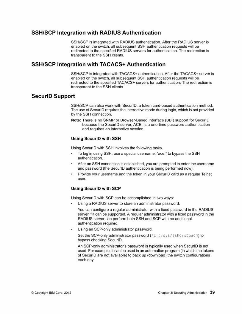
© Copyright IBM Corp. 2012 Chapter 3: Securing Administration 39
SSH/SCP Integration with RADIUS Authentication
SSH/SCP is integrated with RADIUS authentication. After the RADIUS server is enabled on the switch, all subsequent SSH authentication requests will be redirected to the specified RADIUS servers for authentication. The redirection is transparent to the SSH clients.
SSH/SCP Integration with TACACS+ Authentication
SSH/SCP is integrated with TACACS+ authentication. After the TACACS+ server is enabled on the switch, all subsequent SSH authentication requests will be redirected to the specified TACACS+ servers for authentication. The redirection is transparent to the SSH clients.
SecurID Support
SSH/SCP can also work with SecurID, a token card-based authentication method. The use of SecurID requires the interactive mode during login, which is not provided by the SSH connection.
Note: There is no SNMP or Browser-Based Interface (BBI) support for SecurID because the SecurID server, ACE, is a one-time password authentication and requires an interactive session.
Using SecurID with SSH
Using SecurID with SSH involves the following tasks.
• To log in using SSH, use a special username, “ace,” to bypass the SSH authentication.
• After an SSH connection is established, you are prompted to enter the username and password (the SecurID authentication is being performed now).
• Provide your username and the token in your SecurID card as a regular Telnet user.
Using SecurID with SCP
Using SecurID with SCP can be accomplished in two ways:
• Using a RADIUS server to store an administrator password.
You can configure a regular administrator with a fixed password in the RADIUS server if it can be supported. A regular administrator with a fixed password in the RADIUS server can perform both SSH and SCP with no additional authentication required.
• Using an SCP-only administrator password.
Set the SCP-only administrator password (/cfg/sys/sshd/scpadm) to bypass checking SecurID.
An SCP-only administrator’s password is typically used when SecurID is not used. For example, it can be used in an automation program (in which the tokens of SecurID are not available) to back up (download) the switch configurations each day.
40 EN4093 10Gb Scalable Switch: Application Guide
Note: The SCP-only administrator’s password must be different from the regular administrator’s password. If the two passwords are the same, the administrator using that password will not be allowed to log in as an SSH user because the switch will recognize him as the SCP-only administrator. The switch will only allow the administrator access to SCP commands.
End User Access Control
IBM Networking OS allows an administrator to define end user accounts that permit end users to perform operation tasks via the switch CLI commands. Once end user accounts are configured and enabled, the switch requires username/password authentication.
For example, an administrator can assign a user, who can then log into the switch and perform operational commands (effective only until the next switch reboot).
Considerations for Configuring End User Accounts
• A maximum of 10 user IDs are supported on the switch.
• IBM Networking OS supports end user support for Console, Telnet, BBI, and SSHv1/v2 access to the switch.
• If RADIUS authentication is used, the user password on the Radius server will override the user password on the EN4093. Also note that the password change command modifies only the user switch password on the switch and has no effect on the user password on the Radius server. Radius authentication and user password cannot be used concurrently to access the switch.
• Passwords can be up to 128 characters in length for TACACS, RADIUS, Telnet, SSH, Console, and Web access.
Strong Passwords
The administrator can require use of Strong Passwords for users to access the EN4093. Strong Passwords enhance security because they make password guessing more difficult.
The following rules apply when Strong Passwords are enabled:
• Each passwords must be 8 to 14 characters
• Within the first 8 characters, the password:
– must have at least one number or one symbol
– must have both upper and lower case letters
– cannot be the same as any four previously used passwords
The following are examples of strong passwords:
• 1234AbcXyz
• Super+User
• Exo1cet2
The administrator can choose the number of days allowed before each password expires. When a strong password expires, the user is allowed to log in one last time (last time) to change the password. A warning provides advance notice for users to change the password.
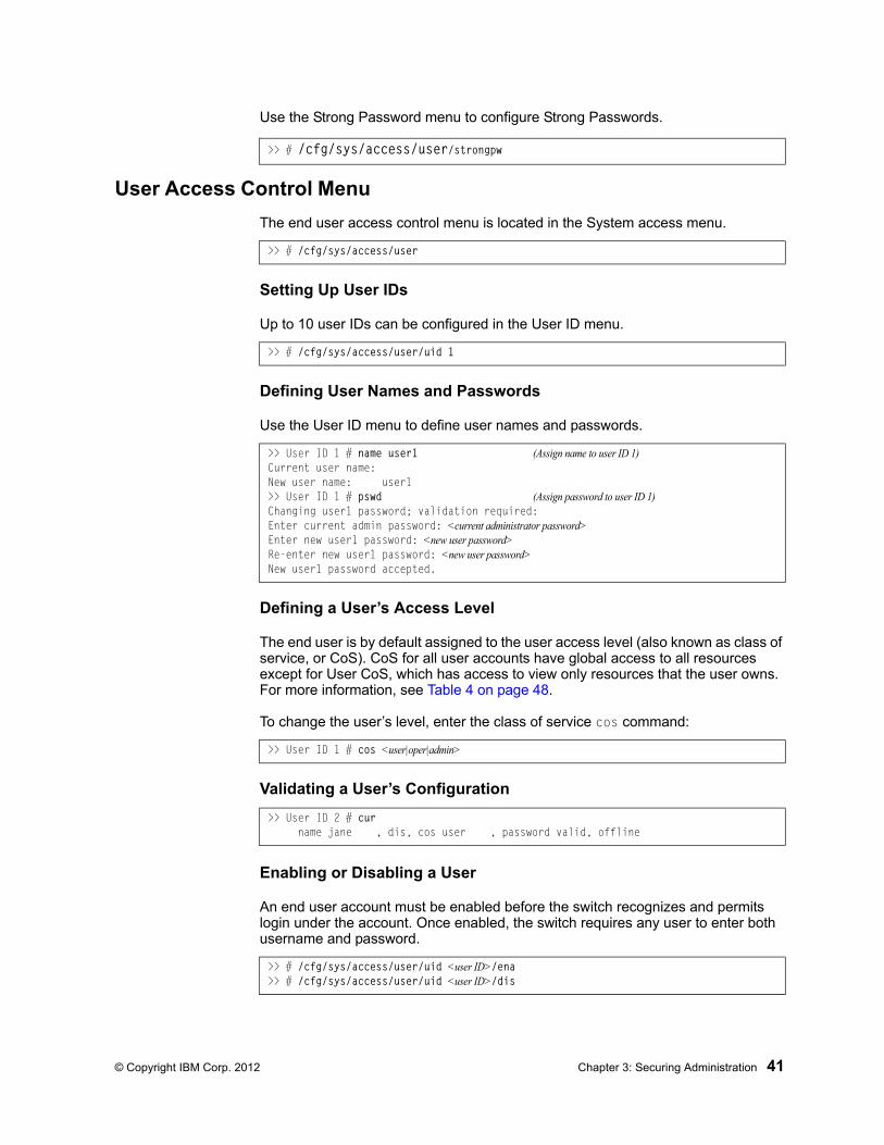
© Copyright IBM Corp. 2012 Chapter 3: Securing Administration 41
Use the Strong Password menu to configure Strong Passwords.
User Access Control Menu
The end user access control menu is located in the System access menu.
Setting Up User IDs
Up to 10 user IDs can be configured in the User ID menu.
Defining User Names and Passwords
Use the User ID menu to define user names and passwords.
Defining a User’s Access Level
The end user is by default assigned to the user access level (also known as class of service, or CoS). CoS for all user accounts have global access to all resources except for User CoS, which has access to view only resources that the user owns. For more information, see Table 4 on page 48.
To change the user’s level, enter the class of service cos command:
Validating a User’s Configuration
Enabling or Disabling a User
An end user account must be enabled before the switch recognizes and permits login under the account. Once enabled, the switch requires any user to enter both username and password.
>> # /cfg/sys/access/user/strongpw
>> # /cfg/sys/access/user
>> # /cfg/sys/access/user/uid 1
>> User ID 1 # name user1 (Assign name to user ID 1)Current user name:New user name: user1>> User ID 1 # pswd (Assign password to user ID 1)Changing user1 password; validation required:Enter current admin password: <current administrator password>Enter new user1 password: <new user password>Re-enter new user1 password: <new user password>New user1 password accepted.
>> User ID 1 # cos <user|oper|admin>
>> User ID 2 # cur name jane , dis, cos user , password valid, offline
>> # /cfg/sys/access/user/uid <user ID>/ena>> # /cfg/sys/access/user/uid <user ID>/dis
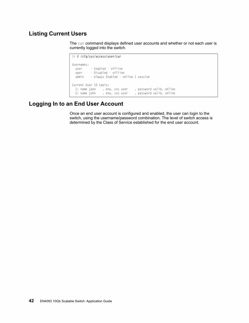
42 EN4093 10Gb Scalable Switch: Application Guide
Listing Current Users
The cur command displays defined user accounts and whether or not each user is currently logged into the switch.
Logging In to an End User Account
Once an end user account is configured and enabled, the user can login to the switch, using the username/password combination. The level of switch access is determined by the Class of Service established for the end user account.
>> # /cfg/sys/access/user/cur
Usernames:user - Enabled - offlineoper - Disabled - offlineadmin - Always Enabled - online 1 session
Current User ID table:1: name jane , ena, cos user , password valid, online2: name john , ena, cos user , password valid, online
© Copyright IBM Corp. 2012 Chapter 3: Securing Administration 43
Protected ModeProtected Mode settings allow the switch administrator to block the management module from making configuration changes that affect switch operation. The switch retains control over those functions.
The following management module functions are disabled when Protected Mode is turned on:
• External Ports: Enabled/Disabled
• External management over all ports: Enabled/Disabled
• Restore Factory Defaults
• New Static IP Configuration
In this release, configuration of the functions listed above are restricted to the local switch when you turn Protected Mode on. In future releases, individual control over each function may be added.
Note: Before you turn Protected Mode on, make sure that external management (Telnet) access to one of the switch’s IP interfaces is enabled.
Use the following command to turn Protected Mode on: /oper/prm/on
If you lose access to the switch through the external ports, use the console port to connect directly to the switch, and configure an IP interface with Telnet access.

44 EN4093 10Gb Scalable Switch: Application Guide

© Copyright IBM Corp. 2012 45
Chapter 4. Authentication & Authorization Protocols
Secure switch management is needed for environments that perform significant management functions across the Internet. The following are some of the functions for secured IPv4 management and device access:
• “RADIUS Authentication and Authorization” on page 46• “TACACS+ Authentication” on page 50• “LDAP Authentication and Authorization” on page 55
Note: IBM Networking OS 7.2 does not support IPv6 for RADIUS, TACACS+ or LDAP.
46 EN4093 10Gb Scalable Switch: Application Guide
RADIUS Authentication and Authorization
IBM Networking OS supports the RADIUS (Remote Authentication Dial-in User Service) method to authenticate and authorize remote administrators for managing the switch. This method is based on a client/server model. The Remote Access Server (RAS)—the switch—is a client to the back-end database server. A remote user (the remote administrator) interacts only with the RAS, not the back-end server and database.
RADIUS authentication consists of the following components:
• A protocol with a frame format that utilizes UDP over IP (based on RFC 2138 and 2866)
• A centralized server that stores all the user authorization information• A client, in this case, the switch
The EN4093—acting as the RADIUS client—communicates to the RADIUS server to authenticate and authorize a remote administrator using the protocol definitions specified in RFC 2138 and 2866. Transactions between the client and the RADIUS server are authenticated using a shared key that is not sent over the network. In addition, the remote administrator passwords are sent encrypted between the RADIUS client (the switch) and the back-end RADIUS server.
How RADIUS Authentication Works
1. Remote administrator connects to the switch and provides user name and password.
2. Using Authentication/Authorization protocol, the switch sends request to authentication server.
3. Authentication server checks the request against the user ID database.
4. Using RADIUS protocol, the authentication server instructs the switch to grant or deny administrative access.
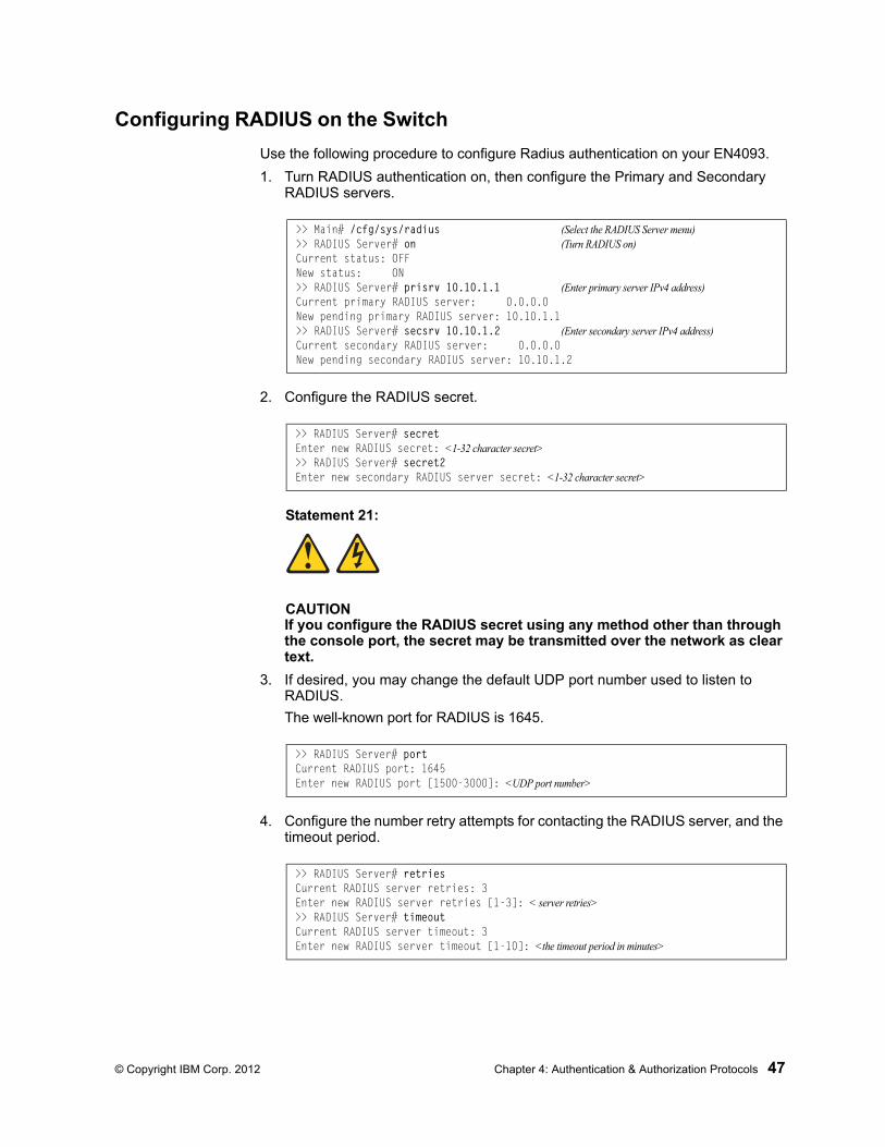
© Copyright IBM Corp. 2012 Chapter 4: Authentication & Authorization Protocols 47
Configuring RADIUS on the Switch
Use the following procedure to configure Radius authentication on your EN4093.
1. Turn RADIUS authentication on, then configure the Primary and Secondary RADIUS servers.
2. Configure the RADIUS secret.
Statement 21:
CAUTIONIf you configure the RADIUS secret using any method other than through the console port, the secret may be transmitted over the network as clear text.
3. If desired, you may change the default UDP port number used to listen to RADIUS.
The well-known port for RADIUS is 1645.
4. Configure the number retry attempts for contacting the RADIUS server, and the timeout period.
>> Main# /cfg/sys/radius (Select the RADIUS Server menu)>> RADIUS Server# on (Turn RADIUS on)Current status: OFFNew status: ON>> RADIUS Server# prisrv 10.10.1.1 (Enter primary server IPv4 address)Current primary RADIUS server: 0.0.0.0New pending primary RADIUS server: 10.10.1.1>> RADIUS Server# secsrv 10.10.1.2 (Enter secondary server IPv4 address)Current secondary RADIUS server: 0.0.0.0New pending secondary RADIUS server: 10.10.1.2
>> RADIUS Server# secretEnter new RADIUS secret: <1-32 character secret>>> RADIUS Server# secret2Enter new secondary RADIUS server secret: <1-32 character secret>
>> RADIUS Server# portCurrent RADIUS port: 1645Enter new RADIUS port [1500-3000]: <UDP port number>
>> RADIUS Server# retriesCurrent RADIUS server retries: 3Enter new RADIUS server retries [1-3]: < server retries>>> RADIUS Server# timeoutCurrent RADIUS server timeout: 3Enter new RADIUS server timeout [1-10]: <the timeout period in minutes>
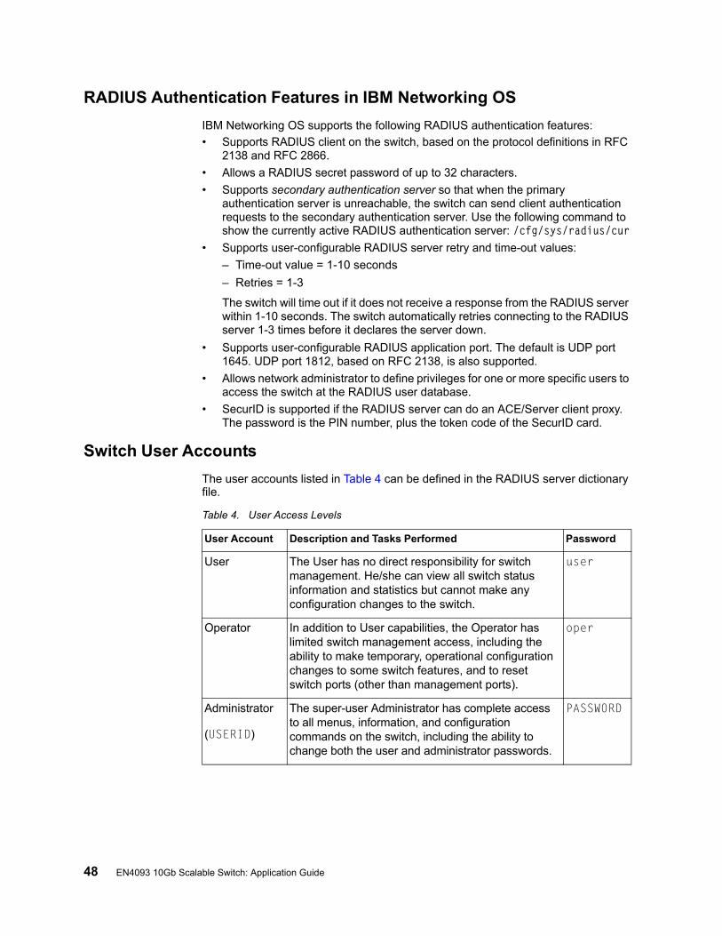
48 EN4093 10Gb Scalable Switch: Application Guide
RADIUS Authentication Features in IBM Networking OS
IBM Networking OS supports the following RADIUS authentication features:
• Supports RADIUS client on the switch, based on the protocol definitions in RFC 2138 and RFC 2866.
• Allows a RADIUS secret password of up to 32 characters.
• Supports secondary authentication server so that when the primary authentication server is unreachable, the switch can send client authentication requests to the secondary authentication server. Use the following command to show the currently active RADIUS authentication server: /cfg/sys/radius/cur
• Supports user-configurable RADIUS server retry and time-out values:
– Time-out value = 1-10 seconds
– Retries = 1-3
The switch will time out if it does not receive a response from the RADIUS server within 1-10 seconds. The switch automatically retries connecting to the RADIUS server 1-3 times before it declares the server down.
• Supports user-configurable RADIUS application port. The default is UDP port 1645. UDP port 1812, based on RFC 2138, is also supported.
• Allows network administrator to define privileges for one or more specific users to access the switch at the RADIUS user database.
• SecurID is supported if the RADIUS server can do an ACE/Server client proxy. The password is the PIN number, plus the token code of the SecurID card.
Switch User Accounts
The user accounts listed in Table 4 can be defined in the RADIUS server dictionary file.
Table 4. User Access Levels
User Account Description and Tasks Performed Password
User The User has no direct responsibility for switch management. He/she can view all switch status information and statistics but cannot make any configuration changes to the switch.
user
Operator In addition to User capabilities, the Operator has limited switch management access, including the ability to make temporary, operational configuration changes to some switch features, and to reset switch ports (other than management ports).
oper
Administrator
(USERID)
The super-user Administrator has complete access to all menus, information, and configuration commands on the switch, including the ability to change both the user and administrator passwords.
PASSW0RD
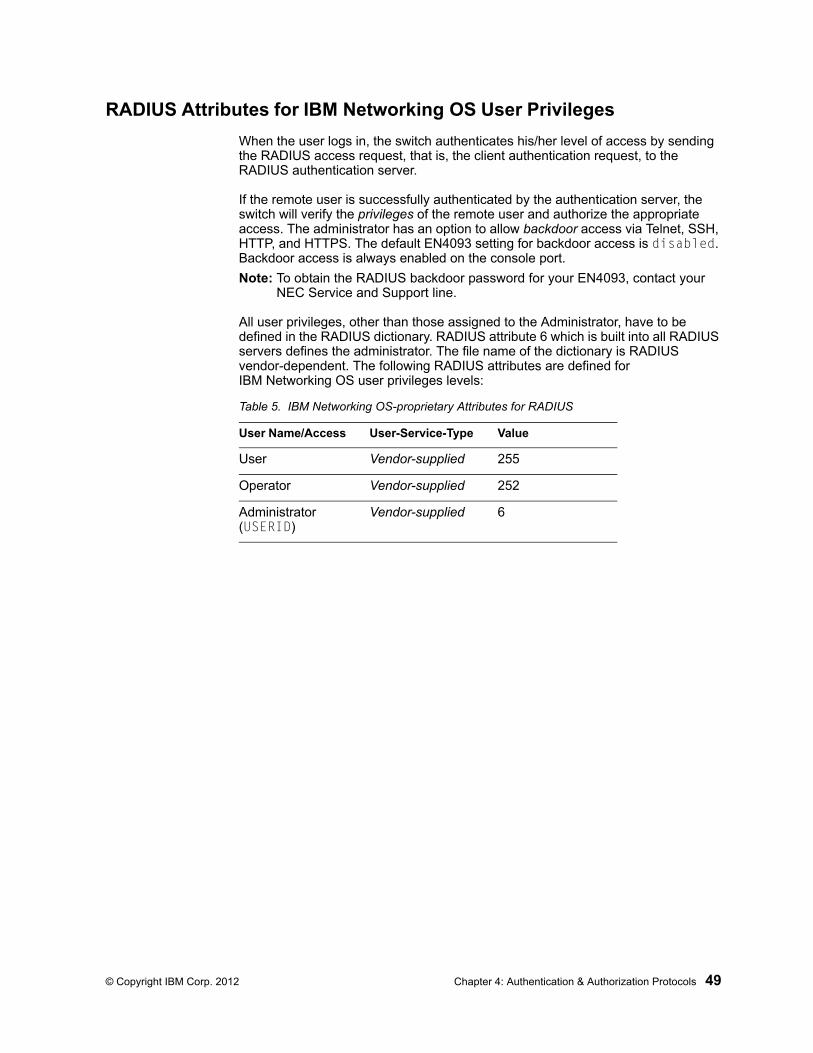
© Copyright IBM Corp. 2012 Chapter 4: Authentication & Authorization Protocols 49
RADIUS Attributes for IBM Networking OS User Privileges
When the user logs in, the switch authenticates his/her level of access by sending the RADIUS access request, that is, the client authentication request, to the RADIUS authentication server.
If the remote user is successfully authenticated by the authentication server, the switch will verify the privileges of the remote user and authorize the appropriate access. The administrator has an option to allow backdoor access via Telnet, SSH, HTTP, and HTTPS. The default EN4093 setting for backdoor access is disabled. Backdoor access is always enabled on the console port.
Note: To obtain the RADIUS backdoor password for your EN4093, contact your NEC Service and Support line.
All user privileges, other than those assigned to the Administrator, have to be defined in the RADIUS dictionary. RADIUS attribute 6 which is built into all RADIUS servers defines the administrator. The file name of the dictionary is RADIUS vendor-dependent. The following RADIUS attributes are defined for IBM Networking OS user privileges levels:
Table 5. IBM Networking OS-proprietary Attributes for RADIUS
User Name/Access User-Service-Type Value
User Vendor-supplied 255
Operator Vendor-supplied 252
Administrator (USERID)
Vendor-supplied 6
50 EN4093 10Gb Scalable Switch: Application Guide
TACACS+ Authentication
IBM Networking OS supports authentication, authorization, and accounting with networks using the Cisco Systems TACACS+ protocol. The EN4093 functions as the Network Access Server (NAS) by interacting with the remote client and initiating authentication and authorization sessions with the TACACS+ access server. The remote user is defined as someone requiring management access to the EN4093 either through a data or management port.
TACACS+ offers the following advantages over RADIUS:
• TACACS+ uses TCP-based connection-oriented transport; whereas RADIUS is UDP-based. TCP offers a connection-oriented transport, while UDP offers best-effort delivery. RADIUS requires additional programmable variables such as re-transmit attempts and time-outs to compensate for best-effort transport, but it lacks the level of built-in support that a TCP transport offers.
• TACACS+ offers full packet encryption whereas RADIUS offers password-only encryption in authentication requests.
• TACACS+ separates authentication, authorization and accounting.
How TACACS+ Authentication Works
TACACS+ works much in the same way as RADIUS authentication as described on page 46.
1. Remote administrator connects to the switch and provides user name and password.
2. Using Authentication/Authorization protocol, the switch sends request to authentication server.
3. Authentication server checks the request against the user ID database.
4. Using TACACS+ protocol, the authentication server instructs the switch to grant or deny administrative access.
During a session, if additional authorization checking is needed, the switch checks with a TACACS+ server to determine if the user is granted permission to use a particular command.
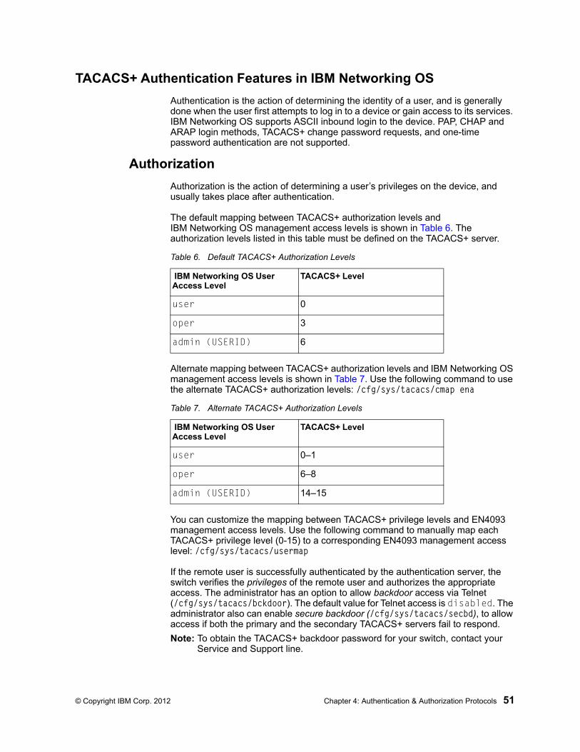
© Copyright IBM Corp. 2012 Chapter 4: Authentication & Authorization Protocols 51
TACACS+ Authentication Features in IBM Networking OS
Authentication is the action of determining the identity of a user, and is generally done when the user first attempts to log in to a device or gain access to its services. IBM Networking OS supports ASCII inbound login to the device. PAP, CHAP and ARAP login methods, TACACS+ change password requests, and one-time password authentication are not supported.
Authorization
Authorization is the action of determining a user’s privileges on the device, and usually takes place after authentication.
The default mapping between TACACS+ authorization levels and IBM Networking OS management access levels is shown in Table 6. The authorization levels listed in this table must be defined on the TACACS+ server.
Alternate mapping between TACACS+ authorization levels and IBM Networking OS management access levels is shown in Table 7. Use the following command to use the alternate TACACS+ authorization levels: /cfg/sys/tacacs/cmap ena
You can customize the mapping between TACACS+ privilege levels and EN4093 management access levels. Use the following command to manually map each TACACS+ privilege level (0-15) to a corresponding EN4093 management access level: /cfg/sys/tacacs/usermap
If the remote user is successfully authenticated by the authentication server, the switch verifies the privileges of the remote user and authorizes the appropriate access. The administrator has an option to allow backdoor access via Telnet (/cfg/sys/tacacs/bckdoor). The default value for Telnet access is disabled. The administrator also can enable secure backdoor (/cfg/sys/tacacs/secbd), to allow access if both the primary and the secondary TACACS+ servers fail to respond.
Note: To obtain the TACACS+ backdoor password for your switch, contact your Service and Support line.
Table 6. Default TACACS+ Authorization Levels
IBM Networking OS User Access Level
TACACS+ Level
user 0
oper 3
admin (USERID) 6
Table 7. Alternate TACACS+ Authorization Levels
IBM Networking OS User Access Level
TACACS+ Level
user 0–1
oper 6–8
admin (USERID) 14–15
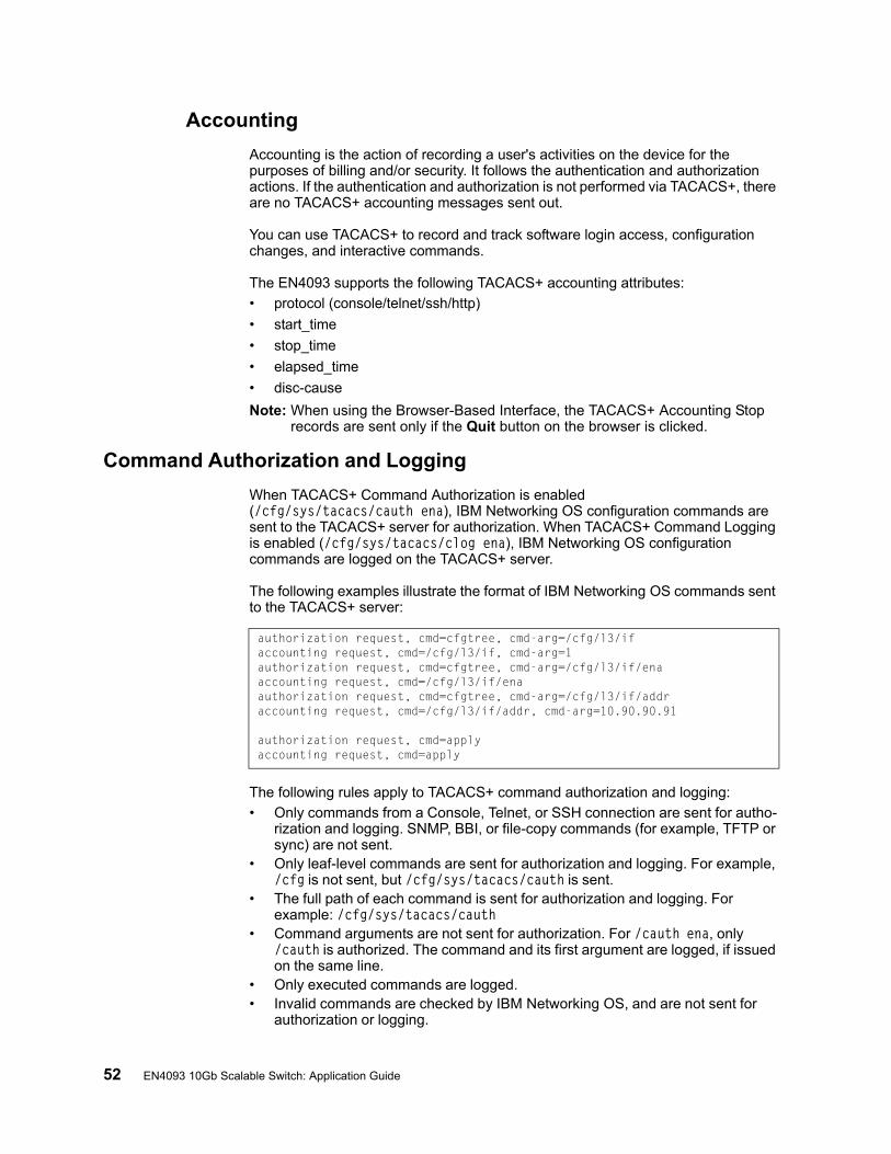
52 EN4093 10Gb Scalable Switch: Application Guide
Accounting
Accounting is the action of recording a user's activities on the device for the purposes of billing and/or security. It follows the authentication and authorization actions. If the authentication and authorization is not performed via TACACS+, there are no TACACS+ accounting messages sent out.
You can use TACACS+ to record and track software login access, configuration changes, and interactive commands.
The EN4093 supports the following TACACS+ accounting attributes:
• protocol (console/telnet/ssh/http)
• start_time
• stop_time
• elapsed_time
• disc-cause
Note: When using the Browser-Based Interface, the TACACS+ Accounting Stop records are sent only if the Quit button on the browser is clicked.
Command Authorization and Logging
When TACACS+ Command Authorization is enabled (/cfg/sys/tacacs/cauth ena), IBM Networking OS configuration commands are sent to the TACACS+ server for authorization. When TACACS+ Command Logging is enabled (/cfg/sys/tacacs/clog ena), IBM Networking OS configuration commands are logged on the TACACS+ server.
The following examples illustrate the format of IBM Networking OS commands sent to the TACACS+ server:
The following rules apply to TACACS+ command authorization and logging:
• Only commands from a Console, Telnet, or SSH connection are sent for autho-rization and logging. SNMP, BBI, or file-copy commands (for example, TFTP or sync) are not sent.
• Only leaf-level commands are sent for authorization and logging. For example, /cfg is not sent, but /cfg/sys/tacacs/cauth is sent.
• The full path of each command is sent for authorization and logging. For example: /cfg/sys/tacacs/cauth
• Command arguments are not sent for authorization. For /cauth ena, only /cauth is authorized. The command and its first argument are logged, if issued on the same line.
• Only executed commands are logged.• Invalid commands are checked by IBM Networking OS, and are not sent for
authorization or logging.
authorization request, cmd=cfgtree, cmd-arg=/cfg/l3/ifaccounting request, cmd=/cfg/l3/if, cmd-arg=1authorization request, cmd=cfgtree, cmd-arg=/cfg/l3/if/enaaccounting request, cmd=/cfg/l3/if/enaauthorization request, cmd=cfgtree, cmd-arg=/cfg/l3/if/addraccounting request, cmd=/cfg/l3/if/addr, cmd-arg=10.90.90.91
authorization request, cmd=applyaccounting request, cmd=apply
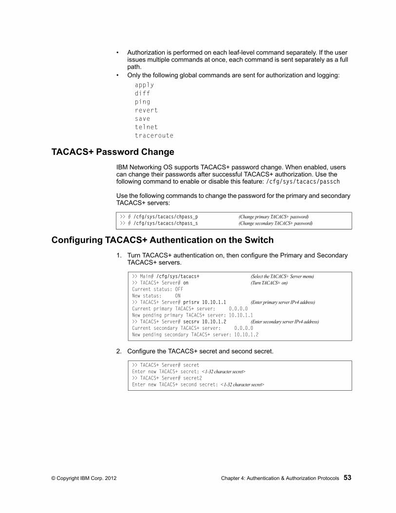
© Copyright IBM Corp. 2012 Chapter 4: Authentication & Authorization Protocols 53
• Authorization is performed on each leaf-level command separately. If the user issues multiple commands at once, each command is sent separately as a full path.
• Only the following global commands are sent for authorization and logging:
applydiffpingrevertsavetelnettraceroute
TACACS+ Password Change
IBM Networking OS supports TACACS+ password change. When enabled, users can change their passwords after successful TACACS+ authorization. Use the following command to enable or disable this feature: /cfg/sys/tacacs/passch
Use the following commands to change the password for the primary and secondary TACACS+ servers:
Configuring TACACS+ Authentication on the Switch
1. Turn TACACS+ authentication on, then configure the Primary and Secondary TACACS+ servers.
2. Configure the TACACS+ secret and second secret.
>> # /cfg/sys/tacacs/chpass_p (Change primary TACACS+ password)>> # /cfg/sys/tacacs/chpass_s (Change secondary TACACS+ password)
>> Main# /cfg/sys/tacacs+ (Select the TACACS+ Server menu)>> TACACS+ Server# on (Turn TACACS+ on)Current status: OFFNew status: ON>> TACACS+ Server# prisrv 10.10.1.1 (Enter primary server IPv4 address)Current primary TACACS+ server: 0.0.0.0New pending primary TACACS+ server: 10.10.1.1>> TACACS+ Server# secsrv 10.10.1.2 (Enter secondary server IPv4 address)Current secondary TACACS+ server: 0.0.0.0New pending secondary TACACS+ server: 10.10.1.2
>> TACACS+ Server# secretEnter new TACACS+ secret: <1-32 character secret>>> TACACS+ Server# secret2Enter new TACACS+ second secret: <1-32 character secret>

54 EN4093 10Gb Scalable Switch: Application Guide
Statement 21:
CAUTIONIf you configure the TACACS+ secret using any method other than a direct console connection, the secret may be transmitted over the network as clear text.
3. If desired, you may change the default TCP port number used to listen to TACACS+. The well-known port for TACACS+ is 49.
4. Configure the number of retry attempts, and the timeout period.
5. Configure custom privilege-level mapping (optional).
6. Apply and save the configuration.
>> TACACS+ Server# portCurrent TACACS+ port: 49Enter new TACACS+ port [1-65000]: <port number>
>> TACACS+ Server# retriesCurrent TACACS+ server retries: 3Enter new TACACS+ server retries [1-3]: < server retries>>> TACACS+ Server# timeCurrent TACACS+ server timeout: 5Enter new TACACS+ server timeout [4-15]: <timeout period in minutes>
>> TACACS+ Server# usermap 2Current privilege mapping for remote privilege 2: not setEnter new local privilege mapping: user>> TACACS+ Server# usermap 3 user>> TACACS+ Server# usermap 4 user>> TACACS+ Server# usermap 5 oper

© Copyright IBM Corp. 2012 Chapter 4: Authentication & Authorization Protocols 55
LDAP Authentication and Authorization
IBM Networking OS supports the LDAP (Lightweight Directory Access Protocol) method to authenticate and authorize remote administrators to manage the switch. LDAP is based on a client/server model. The switch acts as a client to the LDAP server. A remote user (the remote administrator) interacts only with the switch, not the back-end server and database.
LDAP authentication consists of the following components:
• A protocol with a frame format that utilizes TCP over IP• A centralized server that stores all the user authorization information• A client, in this case, the switch
Each entry in the LDAP server is referenced by its Distinguished Name (DN). The DN consists of the user-account name concatenated with the LDAP domain name. If the user-account name is John, the following is an example DN:
uid=John,ou=people,dc=domain,dc=com
Configuring the LDAP Server
EN4093 user groups and user accounts must reside within the same domain. On the LDAP server, configure the domain to include EN4093 user groups and user accounts, as follows:
• User Accounts:
Use the uid attribute to define each individual user account.
• User Groups:
Use the members attribute in the groupOfNames object class to create the user groups. The first word of the common name for each user group must be equal to the user group names defined in the EN4093, as follows:
– admin (USERID)– oper– user
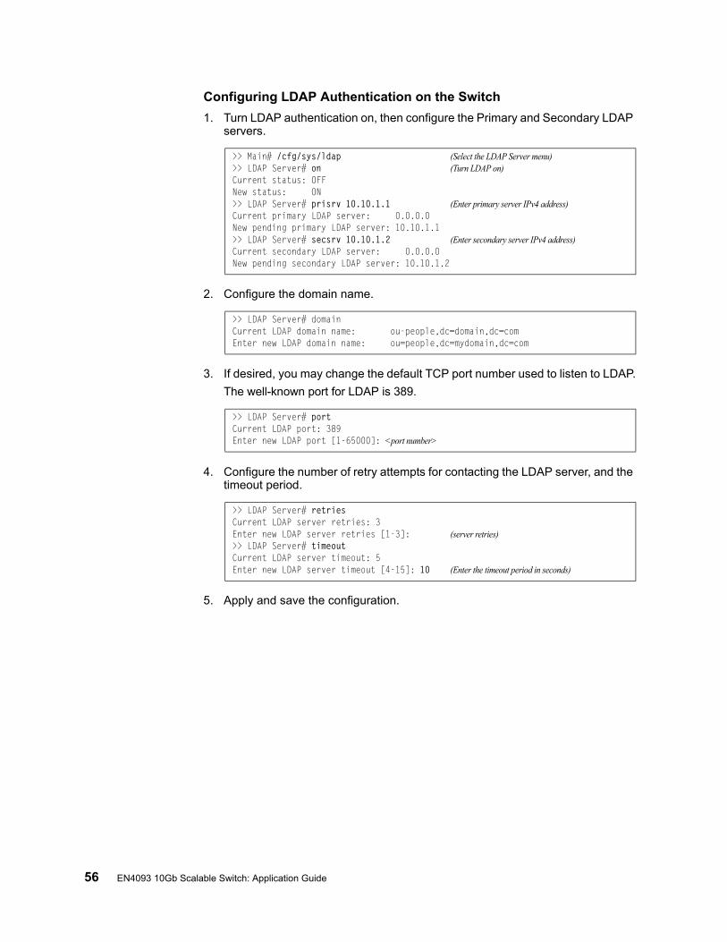
56 EN4093 10Gb Scalable Switch: Application Guide
Configuring LDAP Authentication on the Switch
1. Turn LDAP authentication on, then configure the Primary and Secondary LDAP servers.
2. Configure the domain name.
3. If desired, you may change the default TCP port number used to listen to LDAP.
The well-known port for LDAP is 389.
4. Configure the number of retry attempts for contacting the LDAP server, and the timeout period.
5. Apply and save the configuration.
>> Main# /cfg/sys/ldap (Select the LDAP Server menu)>> LDAP Server# on (Turn LDAP on)Current status: OFFNew status: ON>> LDAP Server# prisrv 10.10.1.1 (Enter primary server IPv4 address)Current primary LDAP server: 0.0.0.0New pending primary LDAP server: 10.10.1.1>> LDAP Server# secsrv 10.10.1.2 (Enter secondary server IPv4 address)Current secondary LDAP server: 0.0.0.0New pending secondary LDAP server: 10.10.1.2
>> LDAP Server# domainCurrent LDAP domain name: ou-people,dc=domain,dc=comEnter new LDAP domain name: ou=people,dc=mydomain,dc=com
>> LDAP Server# portCurrent LDAP port: 389Enter new LDAP port [1-65000]: <port number>
>> LDAP Server# retriesCurrent LDAP server retries: 3Enter new LDAP server retries [1-3]: (server retries)>> LDAP Server# timeoutCurrent LDAP server timeout: 5Enter new LDAP server timeout [4-15]: 10 (Enter the timeout period in seconds)
© Copyright IBM Corp. 2012 57
Chapter 5. 802.1X Port-Based Network Access Control
Port-Based Network Access control provides a means of authenticating and authorizing devices attached to a LAN port that has point-to-point connection characteristics. It prevents access to ports that fail authentication and authorization. This feature provides security to ports of the EN4093 10Gb Scalable Switch (EN4093) that connect to blade servers.
The following topics are discussed in this section:
• “Extensible Authentication Protocol over LAN” on page 58• “EAPoL Authentication Process” on page 59• “EAPoL Port States” on page 61• “Guest VLAN” on page 61• “Supported RADIUS Attributes” on page 62• “EAPoL Configuration Guidelines” on page 64
58 EN4093 10Gb Scalable Switch: Application Guide
Extensible Authentication Protocol over LAN
IBM Networking OS can provide user-level security for its ports using the IEEE 802.1X protocol, which is a more secure alternative to other methods of port-based network access control. Any device attached to an 802.1X-enabled port that fails authentication is prevented access to the network and denied services offered through that port.
The 802.1X standard describes port-based network access control using Extensible Authentication Protocol over LAN (EAPoL). EAPoL provides a means of authenticating and authorizing devices attached to a LAN port that has point-to-point connection characteristics and of preventing access to that port in cases of authentication and authorization failures.
EAPoL is a client-server protocol that has the following components:
• Supplicant or Client The Supplicant is a device that requests network access and provides the required credentials (user name and password) to the Authenticator and the Authenticator Server.
• Authenticator The Authenticator enforces authentication and controls access to the network. The Authenticator grants network access based on the information provided by the Supplicant and the response from the Authentication Server. The Authenticator acts as an intermediary between the Supplicant and the Authentication Server: requesting identity information from the client, forwarding that information to the Authentication Server for validation, relaying the server’s responses to the client, and authorizing network access based on the results of the authentication exchange. The EN4093 acts as an Authenticator.
• Authentication ServerThe Authentication Server validates the credentials provided by the Supplicant to determine if the Authenticator should grant access to the network. The Authentication Server may be co-located with the Authenticator. The EN4093 relies on external RADIUS servers for authentication.
Upon a successful authentication of the client by the server, the 802.1X-controlled port transitions from unauthorized to authorized state, and the client is allowed full access to services through the port. When the client sends an EAP-Logoff message to the authenticator, the port will transition from authorized to unauthorized state.
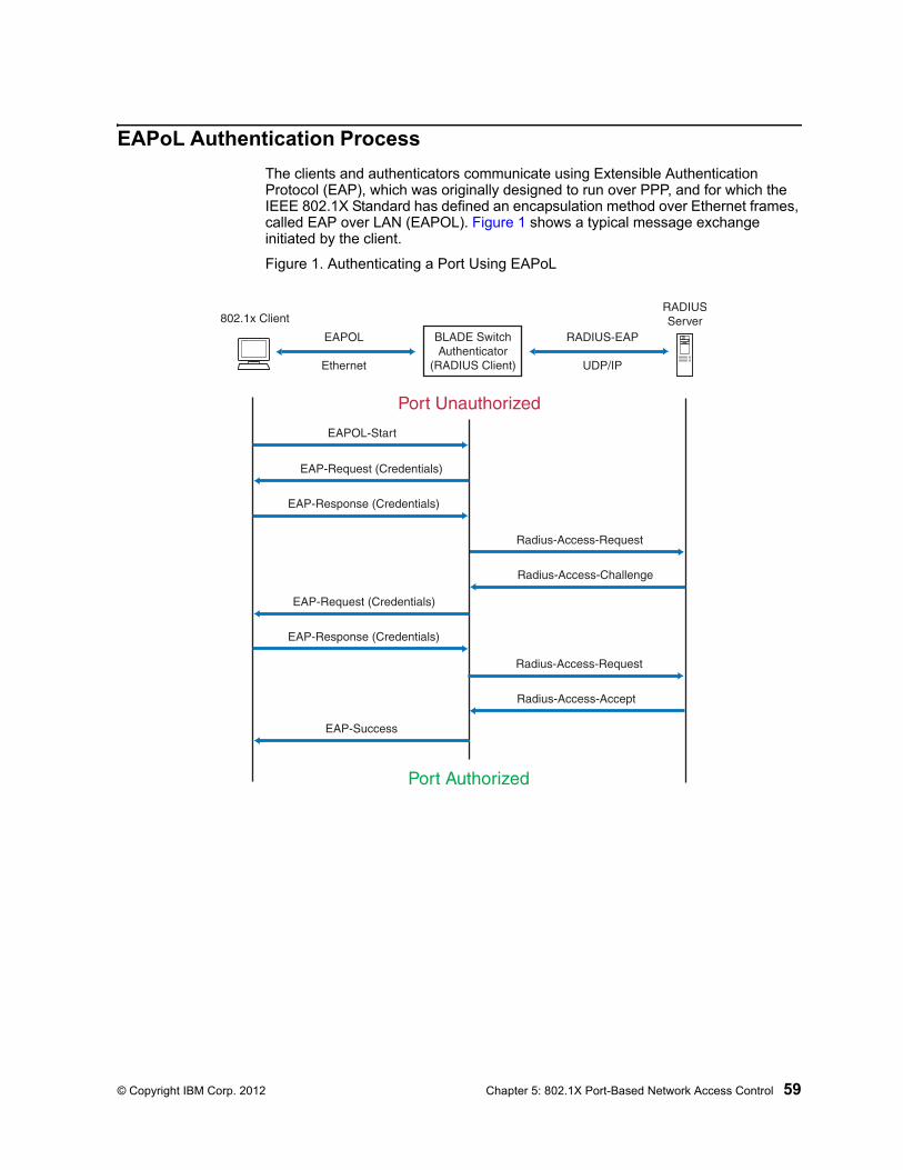
© Copyright IBM Corp. 2012 Chapter 5: 802.1X Port-Based Network Access Control 59
EAPoL Authentication Process
The clients and authenticators communicate using Extensible Authentication Protocol (EAP), which was originally designed to run over PPP, and for which the IEEE 802.1X Standard has defined an encapsulation method over Ethernet frames, called EAP over LAN (EAPOL). Figure 1 shows a typical message exchange initiated by the client.
Figure 1. Authenticating a Port Using EAPoL
802.1x ClientRADIUSServer
Radius-Access-Request
Radius-Access-Challenge
Radius-Access-Request
Radius-Access-Accept
EAP-Request (Credentials)
EAP-Response (Credentials)
EAP-Success
EAP-Request (Credentials)
EAP-Response (Credentials)
EAPOL-Start
Port Authorized
Port Unauthorized
BLADE SwitchAuthenticator
(RADIUS Client)
EAPOL
Ethernet
RADIUS-EAP
UDP/IP
60 EN4093 10Gb Scalable Switch: Application Guide
EAPoL Message Exchange
During authentication, EAPOL messages are exchanged between the client and the EN4093 authenticator, while RADIUS-EAP messages are exchanged between the EN4093 authenticator and the RADIUS server.
Authentication is initiated by one of the following methods:
• The EN4093 authenticator sends an EAP-Request/Identity packet to the client
• The client sends an EAPOL-Start frame to the EN4093 authenticator, which responds with an EAP-Request/Identity frame.
The client confirms its identity by sending an EAP-Response/Identity frame to the EN4093 authenticator, which forwards the frame encapsulated in a RADIUS packet to the server.
The RADIUS authentication server chooses an EAP-supported authentication algorithm to verify the client’s identity, and sends an EAP-Request packet to the client via the EN4093 authenticator. The client then replies to the RADIUS server with an EAP-Response containing its credentials.
Upon a successful authentication of the client by the server, the 802.1X-controlled port transitions from unauthorized to authorized state, and the client is allowed full access to services through the controlled port. When the client later sends an EAPOL-Logoff message to the EN4093 authenticator, the port transitions from authorized to unauthorized state.
If a client that does not support 802.1X connects to an 802.1X-controlled port, the EN4093 authenticator requests the client's identity when it detects a change in the operational state of the port. The client does not respond to the request, and the port remains in the unauthorized state.
Note: When an 802.1X-enabled client connects to a port that is not 802.1X-controlled, the client initiates the authentication process by sending an EAPOL-Start frame. When no response is received, the client retransmits the request for a fixed number of times. If no response is received, the client assumes the port is in authorized state, and begins sending frames, even if the port is unauthorized.
© Copyright IBM Corp. 2012 Chapter 5: 802.1X Port-Based Network Access Control 61
EAPoL Port States
The state of the port determines whether the client is granted access to the network, as follows:
• UnauthorizedWhile in this state the port discards all ingress and egress traffic except EAP packets.
• AuthorizedWhen the client is successfully authenticated, the port transitions to the authorized state allowing all traffic to and from the client to flow normally.
• Force UnauthorizedYou can configure this state that denies all access to the port.
• Force AuthorizedYou can configure this state that allows full access to the port.
Use the 802.1X Global Configuration Menu (/cfg/l2/8021x/global) to configure 802.1X authentication for all ports in the switch. Use the 802.1X Port Menu (/cfg/l2/8021x/port <x>) to configure a single port.
Guest VLAN
The guest VLAN provides limited access to unauthenticated ports. The guest VLAN can be configured from the following menu:
Client ports that have not received an EAPOL response are placed into the Guest VLAN, if one is configured on the switch. Once the port is authenticated, it is moved from the Guest VLAN to its configured VLAN.
When Guest VLAN enabled, the following considerations apply while a port is in the unauthenticated state:
• The port is placed in the guest VLAN.
• The Port VLAN ID (PVID) is changed to the Guest VLAN ID.
• Port tagging is disabled on the port.
>> # /cfg/l2/8021x/global/gvlan

62 EN4093 10Gb Scalable Switch: Application Guide
Supported RADIUS Attributes
The 802.1X Authenticator relies on external RADIUS servers for authentication with EAP. Table 8lists the RADIUS attributes that are supported as part of RADIUS-EAP authentication based on the guidelines specified in Annex D of the 802.1X standard and RFC 3580.
Table 8. Support for RADIUS Attributes
# Attribute Attribute Value A-R
A-A
A-C
A-R
1 User-Name The value of the Type-Data field from the supplicant’s EAP-Response/Identity message. If the Identity is unknown (i.e. Type-Data field is zero bytes in length), this attribute will have the same value as the Calling-Station-Id.
1 0-1 0 0
4 NAS-IP-Address IPv4 address of the authenticator used for Radius communication.
1 0 0 0
5 NAS-Port Port number of the authenticator port to which the supplicant is attached.
1 0 0 0
24 State Server-specific value. This is sent unmodified back to the server in an Access-Request that is in response to an Access-Challenge.
0-1 0-1 0-1 0
30 Called-Station-ID The MAC address of the authenticator encoded as an ASCII string in canonical format, such as 000D5622E3 9F.
1 0 0 0
31 Calling-Station-ID The MAC address of the supplicant encoded as an ASCII string in canonical format, such as 00034B436206.
1 0 0 0
64 Tunnel-Type Only VLAN (type 13) is currently supported (for 802.1X RADIUS VLAN assignment). The attribute must be untagged (the Tag field must be 0).
0 0-1 0 0
65 Tunnel-Medium-Type
Only 802 (type 6) is currently supported (for 802.1X RADIUS VLAN assignment). The attribute must be untagged (the Tag field must be 0).
0 0-1 0 0
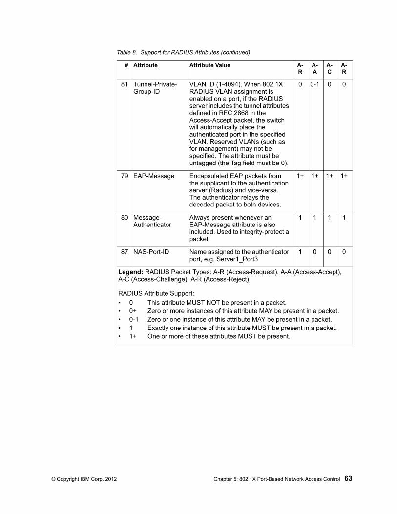
© Copyright IBM Corp. 2012 Chapter 5: 802.1X Port-Based Network Access Control 63
81 Tunnel-Private-Group-ID
VLAN ID (1-4094). When 802.1X RADIUS VLAN assignment is enabled on a port, if the RADIUS server includes the tunnel attributes defined in RFC 2868 in the Access-Accept packet, the switch will automatically place the authenticated port in the specified VLAN. Reserved VLANs (such as for management) may not be specified. The attribute must be untagged (the Tag field must be 0).
0 0-1 0 0
79 EAP-Message Encapsulated EAP packets from the supplicant to the authentication server (Radius) and vice-versa. The authenticator relays the decoded packet to both devices.
1+ 1+ 1+ 1+
80 Message-Authenticator
Always present whenever an EAP-Message attribute is also included. Used to integrity-protect a packet.
1 1 1 1
87 NAS-Port-ID Name assigned to the authenticator port, e.g. Server1_Port3
1 0 0 0
Legend: RADIUS Packet Types: A-R (Access-Request), A-A (Access-Accept), A-C (Access-Challenge), A-R (Access-Reject)
RADIUS Attribute Support:
• 0 This attribute MUST NOT be present in a packet.• 0+ Zero or more instances of this attribute MAY be present in a packet.• 0-1 Zero or one instance of this attribute MAY be present in a packet.• 1 Exactly one instance of this attribute MUST be present in a packet.• 1+ One or more of these attributes MUST be present.
Table 8. Support for RADIUS Attributes (continued)
# Attribute Attribute Value A-R
A-A
A-C
A-R
64 EN4093 10Gb Scalable Switch: Application Guide
EAPoL Configuration Guidelines
When configuring EAPoL, consider the following guidelines:
• The 802.1X port-based authentication is currently supported only in point-to-point configurations, that is, with a single supplicant connected to an 802.1X-enabled switch port.
• When 802.1X is enabled, a port has to be in the authorized state before any other Layer 2 feature can be operationally enabled. For example, the STG state of a port is operationally disabled while the port is in the unauthorized state.
• The 802.1X supplicant capability is not supported. Therefore, none of its ports can successfully connect to an 802.1X-enabled port of another device, such as another switch, that acts as an authenticator, unless access control on the remote port is disabled or is configured in forced-authorized mode. For example, if a EN4093 is connected to another EN4093, and if 802.1X is enabled on both switches, the two connected ports must be configured in force-authorized mode.
• Unsupported 802.1X attributes include Service-Type, Session-Timeout, and Termination-Action.
• RADIUS accounting service for 802.1X-authenticated devices or users is not currently supported.
• Configuration changes performed using SNMP and the standard 802.1X MIB will take effect immediately.

© Copyright IBM Corp. 2012 65
Chapter 6. Access Control Lists
Access Control Lists (ACLs) are filters that permit or deny traffic for security purposes. They can also be used with QoS to classify and segment traffic in order to provide different levels of service to different traffic types. Each filter defines the conditions that must match for inclusion in the filter, and also the actions that are performed when a match is made.
IBM Networking OS 7.2 supports the following ACLs:
• IPv4 ACLs
Up to 640 ACLs are supported for networks that use IPv4 addressing. IPv4 ACLs are configured using the following CLI menu:
• IPv6 ACLs
Up to 128 ACLs are supported for networks that use IPv6 addressing. IPv6 ACLs are configured using the following CLI menu:
• Management ACLs
Up to 128 MACLs are supported. ACLs for the different types of management protocols (Telnet, HTTPS, etc.) provide greater granularity for securing management traffic. Management ACLs are configured using the following CLI menu:
• VLAN Maps (VMaps)
Up to 128 VLAN Maps are supported for attaching filters to VLANs rather than ports. See “VLAN Maps” on page 74 for details.
# /cfg/acl/acl <ACL number>
# /cfg/acl/acl6 <ACL number>
# /cfg/acl/macl <ACL number>
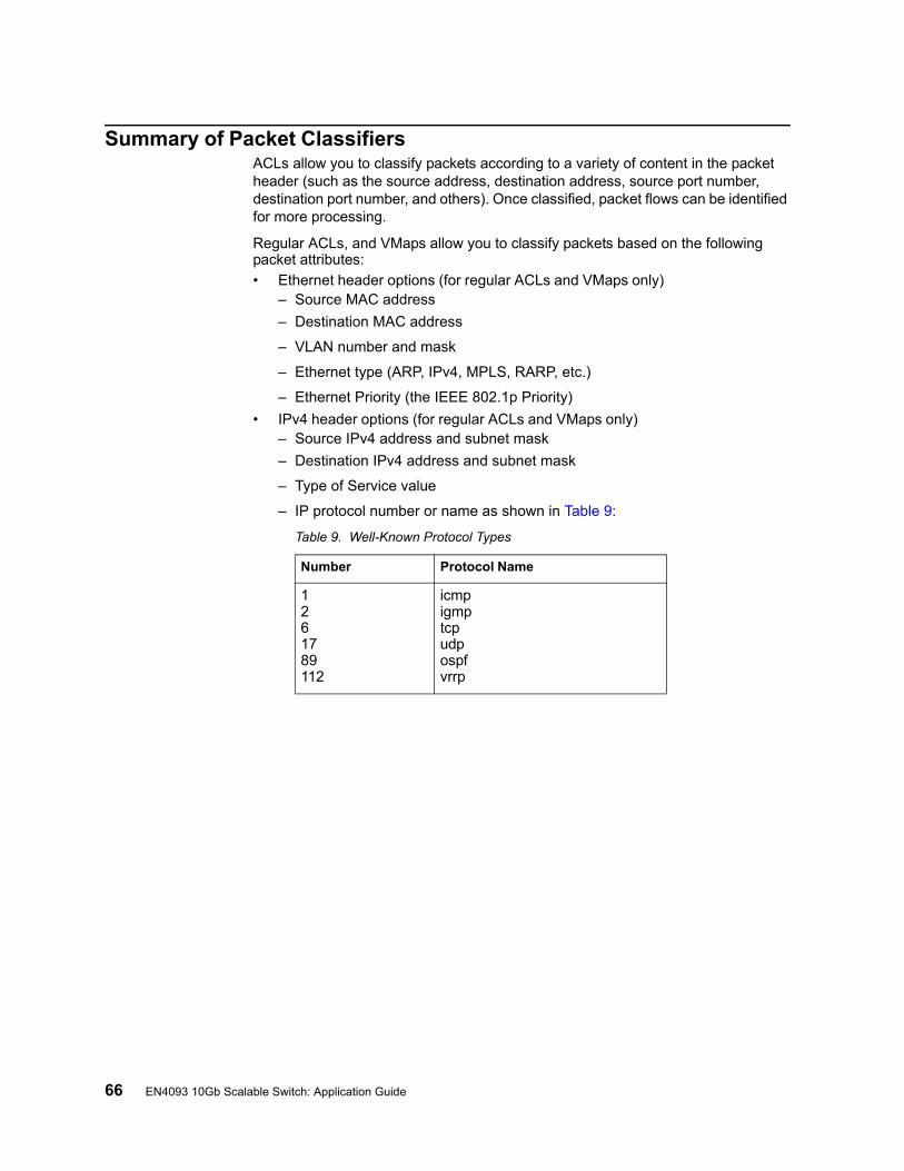
66 EN4093 10Gb Scalable Switch: Application Guide
Summary of Packet ClassifiersACLs allow you to classify packets according to a variety of content in the packet header (such as the source address, destination address, source port number, destination port number, and others). Once classified, packet flows can be identified for more processing.
Regular ACLs, and VMaps allow you to classify packets based on the following packet attributes:
• Ethernet header options (for regular ACLs and VMaps only)– Source MAC address
– Destination MAC address
– VLAN number and mask
– Ethernet type (ARP, IPv4, MPLS, RARP, etc.)
– Ethernet Priority (the IEEE 802.1p Priority)
• IPv4 header options (for regular ACLs and VMaps only)– Source IPv4 address and subnet mask
– Destination IPv4 address and subnet mask
– Type of Service value
– IP protocol number or name as shown in Table 9:
Table 9. Well-Known Protocol Types
Number Protocol Name
1261789112
icmpigmptcpudpospfvrrp
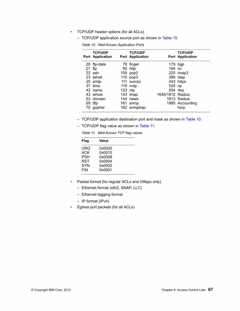
© Copyright IBM Corp. 2012 Chapter 6: Access Control Lists 67
• TCP/UDP header options (for all ACLs)
– TCP/UDP application source port as shown in Table 10.
– TCP/UDP application destination port and mask as shown in Table 10.
– TCP/UDP flag value as shown in Table 11.
• Packet format (for regular ACLs and VMaps only)
– Ethernet format (eth2, SNAP, LLC)
– Ethernet tagging format
– IP format (IPv4)
• Egress port packets (for all ACLs)
Table 10. Well-Known Application Ports
PortTCP/UDPApplication Port
TCP/UDPApplication Port
TCP/UDPApplication
2021222325374243536970
ftp-dataftpsshtelnetsmtptimenamewhoisdomaintftpgopher
7980
109110111119123143144161162
fingerhttppop2pop3sunrpcnntpntpimapnewssnmpsnmptrap
179194220389443520554
1645/181218131985
bgpircimap3ldaphttpsriprtspRadiusRadius Accountinghsrp
Table 11. Well-Known TCP flag values
Flag Value
URGACKPSHRSTSYNFIN
0x00200x00100x00080x00040x00020x0001
68 EN4093 10Gb Scalable Switch: Application Guide
Summary of ACL Actions
Once classified using ACLs, the identified packet flows can be processed differently. For each ACL, an action can be assigned. The action determines how the switch treats packets that match the classifiers assigned to the ACL. EN4093 ACL actions include the following:
• Pass or Drop the packet
• Re-mark the packet with a new DiffServ Code Point (DSCP)
• Re-mark the 802.1p field
• Set the COS queue
Assigning Individual ACLs to a Port
Once you configure an ACL, you must assign the ACL to the appropriate ports. Each port can accept multiple ACLs, and each ACL can be applied for multiple ports. ACLs can be assigned individually, or in groups.
To assign an individual ACLs to a port, use the following commands:
When multiple ACLs are assigned to a port, higher-priority ACLs are considered first, and their action takes precedence over lower-priority ACLs. ACL order of precedence is discussed in the next section.
To create and assign ACLs in groups, see “ACL Groups” on page 69.
ACL Order of Precedence
When multiple ACLs are assigned to a port, they are evaluated in numeric sequence, based on the ACL number. Lower-numbered ACLs take precedence over higher-numbered ACLs. For example, ACL 1 (if assigned to the port) is evaluated first and has top priority.
If multiple ACLs match the port traffic, only the action of the one with the lowest ACL number is applied. The others are ignored.
The ACL number is the sole factor in determining ACL order of precedence. The order in which ACLs are applied to a port does not affect the order of precedence, nor does the ACL Group number (see “ACL Groups” on page 69), the order in which an ACL is assigned to an ACL Group, or the order in which the ACL Group is assigned to a port.
If no assigned ACL matches the port traffic, no ACL action is applied.
# /cfg/port <x>/aclqos/add acl <ACL number> (For regular ACLs)
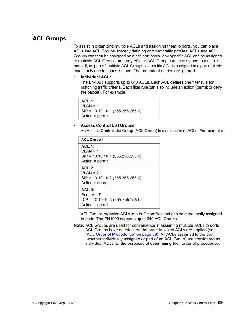
© Copyright IBM Corp. 2012 Chapter 6: Access Control Lists 69
ACL GroupsTo assist in organizing multiple ACLs and assigning them to ports, you can place ACLs into ACL Groups, thereby defining complex traffic profiles. ACLs and ACL Groups can then be assigned on a per-port basis. Any specific ACL can be assigned to multiple ACL Groups, and any ACL or ACL Group can be assigned to multiple ports. If, as part of multiple ACL Groups, a specific ACL is assigned to a port multiple times, only one instance is used. The redundant entries are ignored.
• Individual ACLsThe EN4093 supports up to 640 ACLs. Each ACL defines one filter rule for matching traffic criteria. Each filter rule can also include an action (permit or deny the packet). For example:
• Access Control List GroupsAn Access Control List Group (ACL Group) is a collection of ACLs. For example:
ACL Groups organize ACLs into traffic profiles that can be more easily assigned to ports. The EN4093 supports up to 640 ACL Groups.
Note: ACL Groups are used for convenience in assigning multiple ACLs to ports. ACL Groups have no effect on the order in which ACLs are applied (see “ACL Order of Precedence” on page 68). All ACLs assigned to the port (whether individually assigned or part of an ACL Group) are considered as individual ACLs for the purposes of determining their order of precedence.
ACL 1:VLAN = 1SIP = 10.10.10.1 (255.255.255.0)Action = permit
ACL Group 1
ACL 1:VLAN = 1SIP = 10.10.10.1 (255.255.255.0)Action = permit
ACL 2:VLAN = 2SIP = 10.10.10.2 (255.255.255.0)Action = deny
ACL 3:Priority = 7DIP = 10.10.10.3 (255.255.255.0)Action = permit

70 EN4093 10Gb Scalable Switch: Application Guide
Assigning ACL Groups to a Port
To assign an ACL Group to a port, use the following command:
ACL Metering and Re-Marking
You can define a profile for the aggregate traffic flowing through the switch by configuring a QoS meter (if desired) and assigning ACLs to ports.
Note: When you add ACLs to a port, make sure they are ordered correctly in terms of precedence (see “ACL Order of Precedence” on page 68).
Actions taken by an ACL are called In-Profile actions. You can configure additional In-Profile and Out-of-Profile actions on a port. Data traffic can be metered, and re-marked to ensure that the traffic flow provides certain levels of service in terms of bandwidth for different types of network traffic.
Metering
QoS metering provides different levels of service to data streams through user-configurable parameters. A meter is used to measure the traffic stream against a traffic profile which you create. Thus, creating meters yields In-Profile and Out-of-Profile traffic for each ACL, as follows:
• In-Profile–If there is no meter configured or if the packet conforms to the meter, the packet is classified as In-Profile.
• Out-of-Profile–If a meter is configured and the packet does not conform to the meter (exceeds the committed rate or maximum burst rate of the meter), the packet is classified as Out-of-Profile.
Using meters, you set a Committed Rate in Kbps (1000 bits per second in each Kbps). All traffic within this Committed Rate is In-Profile. Additionally, you can set a Maximum Burst Size that specifies an allowed data burst larger than the Committed Rate for a brief period. These parameters define the In-Profile traffic.
Meters keep the sorted packets within certain parameters. You can configure a meter on an ACL, and perform actions on metered traffic, such as packet re-marking.
Re-Marking
Re-marking allows for the treatment of packets to be reset based on new network specifications or desired levels of service. You can configure the ACL to re-mark a packet as follows:
• Change the DSCP value of a packet, used to specify the service level that traffic should receive.
• Change the 802.1p priority of a packet.
# /cfg/port <x>/aclqos/add grp 20
© Copyright IBM Corp. 2012 Chapter 6: Access Control Lists 71
ACL Port Mirroring
For regular ACLs and VMaps, packets that match an ACL on a specific port can be mirrored to another switch port for network diagnosis and monitoring.
The source port for the mirrored packets cannot be a portchannel, but may be a member of a portchannel.
The destination port to which packets are mirrored must be a physical port.
If the ACL or VMap has an action (permit, drop, etc.) assigned, it cannot be used to mirror packets for that ACL.
Use the following commands to add mirroring to an ACL:
• For regular ACLs:
The ACL must be also assigned to it target ports as usual (see “Assigning Individual ACLs to a Port” on page 68, or “Assigning ACL Groups to a Port” on page 70).
• For VMaps (see “VLAN Maps” on page 74):
Viewing ACL Statistics
ACL statistics display how many packets have “hit” (matched) each ACL. Use ACL statistics to check filter performance or to debug the ACL filter configuration.
You must enable statistics for each ACL that you wish to monitor:
# /cfg/acl/acl <ACL number>/mirrorMirror Options Menu# port <mirror source port>Mirror Options Menu# dest <monitor destination port>|none
# /cfg/acl/vmap <VMap number>/mirrorMirror Options Menu# port <mirror source port>Mirror Options Menu# dest <monitor destination port>|none
# /cfg/acl/acl <ACL number>/stats ena
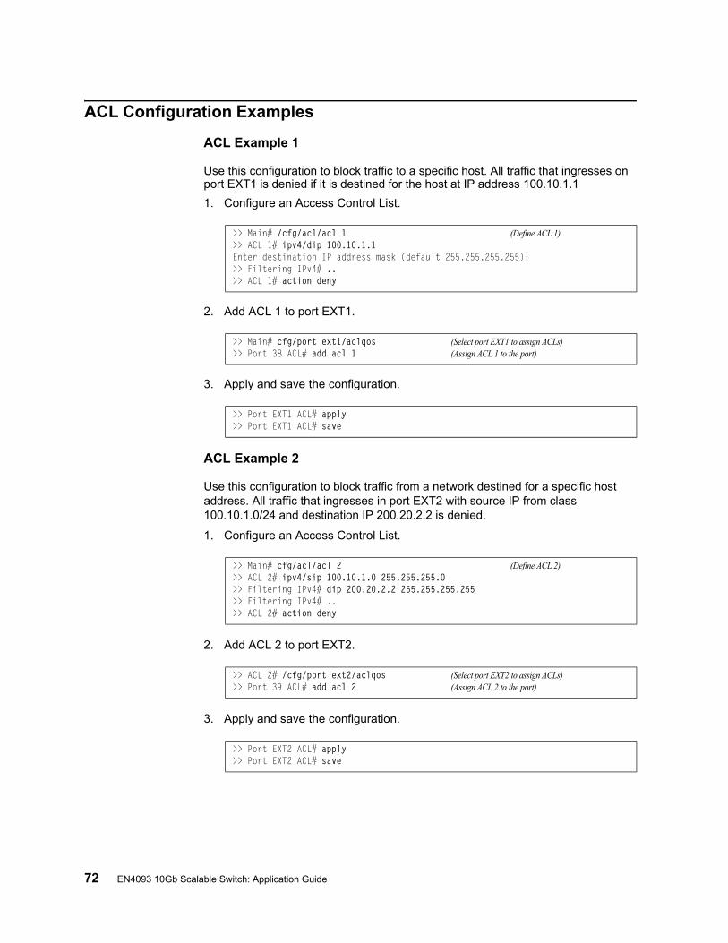
72 EN4093 10Gb Scalable Switch: Application Guide
ACL Configuration Examples
ACL Example 1
Use this configuration to block traffic to a specific host. All traffic that ingresses on port EXT1 is denied if it is destined for the host at IP address 100.10.1.1
1. Configure an Access Control List.
2. Add ACL 1 to port EXT1.
3. Apply and save the configuration.
ACL Example 2
Use this configuration to block traffic from a network destined for a specific host address. All traffic that ingresses in port EXT2 with source IP from class 100.10.1.0/24 and destination IP 200.20.2.2 is denied.
1. Configure an Access Control List.
2. Add ACL 2 to port EXT2.
3. Apply and save the configuration.
>> Main# /cfg/acl/acl 1 (Define ACL 1)>> ACL 1# ipv4/dip 100.10.1.1Enter destination IP address mask (default 255.255.255.255):>> Filtering IPv4# ..>> ACL 1# action deny
>> Main# cfg/port ext1/aclqos (Select port EXT1 to assign ACLs)>> Port 38 ACL# add acl 1 (Assign ACL 1 to the port)
>> Port EXT1 ACL# apply>> Port EXT1 ACL# save
>> Main# cfg/acl/acl 2 (Define ACL 2)>> ACL 2# ipv4/sip 100.10.1.0 255.255.255.0>> Filtering IPv4# dip 200.20.2.2 255.255.255.255>> Filtering IPv4# ..>> ACL 2# action deny
>> ACL 2# /cfg/port ext2/aclqos (Select port EXT2 to assign ACLs)>> Port 39 ACL# add acl 2 (Assign ACL 2 to the port)
>> Port EXT2 ACL# apply>> Port EXT2 ACL# save
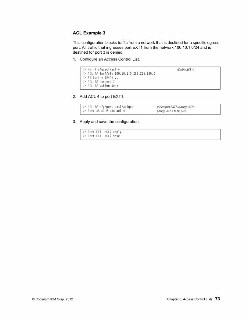
© Copyright IBM Corp. 2012 Chapter 6: Access Control Lists 73
ACL Example 3
This configuration blocks traffic from a network that is destined for a specific egress port. All traffic that ingresses port EXT1 from the network 100.10.1.0/24 and is destined for port 3 is denied.
1. Configure an Access Control List.
2. Add ACL 4 to port EXT1.
3. Apply and save the configuration.
>> Main# cfg/acl/acl 4 (Define ACL 4)>> ACL 4# ipv4/sip 100.10.1.0 255.255.255.0>> Filtering IPv4# ..>> ACL 4# egrport 3>> ACL 4# action deny
>> ACL 4# cfg/port ext1/aclqos (Select port EXT1 to assign ACLs)>> Port 38 ACL# add acl 4 (Assign ACL 4 to the port)
>> Port EXT1 ACL# apply>> Port EXT1 ACL# save
74 EN4093 10Gb Scalable Switch: Application Guide
VLAN Maps
A VLAN map (VMAP) is an ACL that can be assigned to a VLAN or VM group rather than to a switch port as with regular ACLs. This is particularly useful in a virtualized environment where traffic filtering and metering policies must follow virtual machines (VMs) as they migrate between hypervisors.
VMAPs are configured from the ACL menu, available with the following CLI command:
The EN4093 supports up to 128 VMAPs.
Individual VMAP filters are configured in the same fashion as regular ACLs, except that VLANs cannot be specified as a filtering criteria (unnecessary, since the VMAP are assigned to a specific VLAN or associated with a VM group VLAN).
Once a VMAP filter is created, it can be assigned or removed using the following configuration commands:
• For a regular VLAN:
• For a VM group (see “VM Group Types” on page 174):
Note: Each VMAP can be assigned to only one VLAN or VM group. However, each VLAN or VM group may have multiple VMAPs assigned to it.
When the optional intports or extports parameter is specified, the action to add or remove the vMAP is applies for either the internal downlink ports or external uplink ports only. If omitted, the operation will be applied to all ports in the associated VLAN or VM group.
Note: VMAPs have a lower priority than port-based ACLs. If both an ACL and a VMAP match a particular packet, both filter actions will be applied as long as there is no conflict. In the event of a conflict, the port ACL will take priority, though switch statistics will count matches for both the ACL and VMAP.
# /cfg/acl/vmap <VMAP ID (1-128)>
/cfg/l2/vlan <VLAN ID>/vmap {add|rem} <VMAP ID> [intports|extports]
/cfg/virt/vmgroup <ID>/vmap {add|rem} <VMAP ID> [intports|extports]
© Copyright IBM Corp. 2012 75
Part 3: Switch BasicsThis section discusses basic switching functions:
• VLANs
• Port Trunking
• Spanning Tree Protocols (Spanning Tree Groups, Rapid Spanning Tree Protocol, and Multiple Spanning Tree Protocol)
• Quality of Service

76 EN4093 10Gb Scalable Switch: Application Guide
© Copyright IBM Corp. 2012 77
Chapter 7. VLANs
This chapter describes network design and topology considerations for using Virtual Local Area Networks (VLANs). VLANs are commonly used to split up groups of network users into manageable broadcast domains, to create logical segmentation of workgroups, and to enforce security policies among logical segments. The following topics are discussed in this chapter:
• “VLANs and Port VLAN ID Numbers” on page 79
• “VLAN Tagging” on page 81
• “VLAN Topologies and Design Considerations” on page 85
• “Protocol-Based VLANs” on page 88
• “Private VLANs” on page 92
Note: Basic VLANs can be configured during initial switch configuration (see “Using the Setup Utility” in the IBM Networking OS 7.2 Command Reference). More comprehensive VLAN configuration can be done from the Command Line Interface (see “VLAN Configuration” as well as “Port Configuration” in the IBM Networking OS 7.2 Command Reference).
78 EN4093 10Gb Scalable Switch: Application Guide
VLANs Overview
Setting up virtual LANs (VLANs) is a way to segment networks to increase network flexibility without changing the physical network topology. With network segmentation, each switch port connects to a segment that is a single broadcast domain. When a switch port is configured to be a member of a VLAN, it is added to a group of ports (workgroup) that belong to one broadcast domain.
Ports are grouped into broadcast domains by assigning them to the same VLAN. Frames received in one VLAN can only be forwarded within that VLAN, and multicast, broadcast, and unknown unicast frames are flooded only to ports in the same VLAN.
The EN4093 automatically supports jumbo frames. This default cannot be manually configured or disabled.
The EN4093 10Gb Scalable Switch (EN4093) supports jumbo frames with a Maximum Transmission Unit (MTU) of 9,216 bytes. Within each frame, 18 bytes are reserved for the Ethernet header and CRC trailer. The remaining space in the frame (up to 9,198 bytes) comprise the packet, which includes the payload of up to 9,000 bytes and any additional overhead, such as 802.1q or VLAN tags. Jumbo frame support is automatic: it is enabled by default, requires no manual configuration, and cannot be manually disabled.
Note: Jumbo frames are not supported for traffic sent to switch management interfaces.
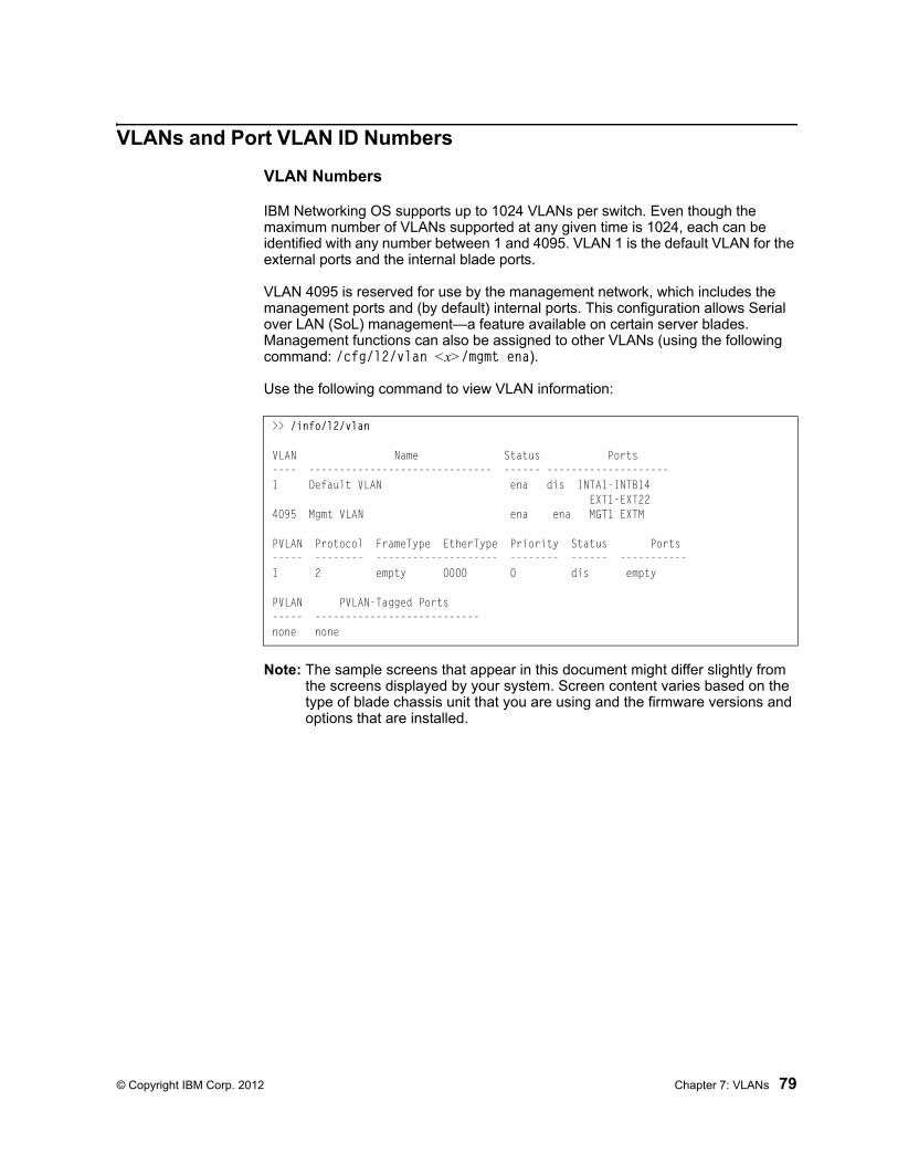
© Copyright IBM Corp. 2012 Chapter 7: VLANs 79
VLANs and Port VLAN ID Numbers
VLAN Numbers
IBM Networking OS supports up to 1024 VLANs per switch. Even though the maximum number of VLANs supported at any given time is 1024, each can be identified with any number between 1 and 4095. VLAN 1 is the default VLAN for the external ports and the internal blade ports.
VLAN 4095 is reserved for use by the management network, which includes the management ports and (by default) internal ports. This configuration allows Serial over LAN (SoL) management—a feature available on certain server blades. Management functions can also be assigned to other VLANs (using the following command: /cfg/l2/vlan <x>/mgmt ena).
Use the following command to view VLAN information:
Note: The sample screens that appear in this document might differ slightly from the screens displayed by your system. Screen content varies based on the type of blade chassis unit that you are using and the firmware versions and options that are installed.
>> /info/l2/vlan
VLAN Name Status Ports---- ------------------------------ ------ --------------------1 Default VLAN ena dis INTA1-INTB14 EXT1-EXT224095 Mgmt VLAN ena ena MGT1 EXTM
PVLAN Protocol FrameType EtherType Priority Status Ports----- -------- -------------------- -------- ------ -----------1 2 empty 0000 0 dis empty
PVLAN PVLAN-Tagged Ports----- ---------------------------none none
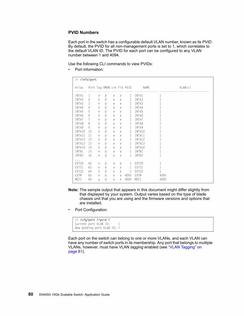
80 EN4093 10Gb Scalable Switch: Application Guide
PVID Numbers
Each port in the switch has a configurable default VLAN number, known as its PVID. By default, the PVID for all non-management ports is set to 1, which correlates to the default VLAN ID. The PVID for each port can be configured to any VLAN number between 1 and 4094.
Use the following CLI commands to view PVIDs:
• Port information:
Note: The sample output that appears in this document might differ slightly from that displayed by your system. Output varies based on the type of blade chassis unit that you are using and the firmware versions and options that are installed.
• Port Configuration:
Each port on the switch can belong to one or more VLANs, and each VLAN can have any number of switch ports in its membership. Any port that belongs to multiple VLANs, however, must have VLAN tagging enabled (see “VLAN Tagging” on page 81).
>> /info/port
Alias Port Tag RMON Lrn Fld PVID NAME VLAN(s)------- ---- --- ---- --- --- ----- -------------- ------------------------------INTA1 1 n d e e 1 INTA1 1INTA2 2 n d e e 1 INTA2 1INTA3 3 n d e e 1 INTA3 1INTA4 4 n d e e 1 INTA4 1INTA5 5 n d e e 1 INTA5 1INTA6 6 n d e e 1 INTA6 1INTA7 7 n d e e 1 INTA7 1INTA8 8 n d e e 1 INTA8 1INTA9 9 n d e e 1 INTA9 1INTA10 10 n d e e 1 INTA10 1INTA11 11 n d e e 1 INTA11 1INTA12 12 n d e e 1 INTA12 1INTA13 13 n d e e 1 INTA13 1INTA14 14 n d e e 1 INTA14 1INTB1 15 n d e e 1 INTB1 1INTB2 16 n d e e 1 INTB2 1...EXT20 62 n d e e 1 EXT20 1EXT21 63 n d e e 1 EXT21 1EXT22 64 n d e e 1 EXT22 1EXTM 65 n d e e 4095 EXTM 4095MGT1 66 y d e e 4095 MGT1 4095
>> /cfg/port 7/pvid 7Current port VLAN ID: 1New pending port VLAN ID: 7
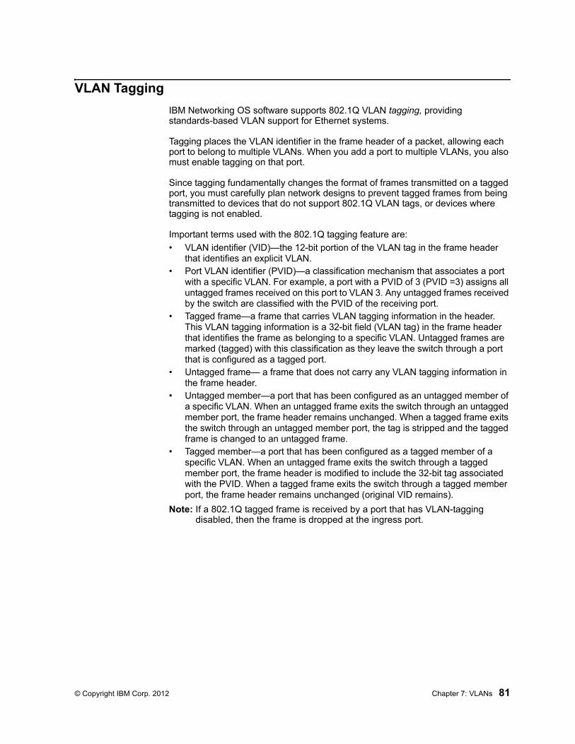
© Copyright IBM Corp. 2012 Chapter 7: VLANs 81
VLAN Tagging
IBM Networking OS software supports 802.1Q VLAN tagging, providing standards-based VLAN support for Ethernet systems.
Tagging places the VLAN identifier in the frame header of a packet, allowing each port to belong to multiple VLANs. When you add a port to multiple VLANs, you also must enable tagging on that port.
Since tagging fundamentally changes the format of frames transmitted on a tagged port, you must carefully plan network designs to prevent tagged frames from being transmitted to devices that do not support 802.1Q VLAN tags, or devices where tagging is not enabled.
Important terms used with the 802.1Q tagging feature are:
• VLAN identifier (VID)—the 12-bit portion of the VLAN tag in the frame header that identifies an explicit VLAN.
• Port VLAN identifier (PVID)—a classification mechanism that associates a port with a specific VLAN. For example, a port with a PVID of 3 (PVID =3) assigns all untagged frames received on this port to VLAN 3. Any untagged frames received by the switch are classified with the PVID of the receiving port.
• Tagged frame—a frame that carries VLAN tagging information in the header. This VLAN tagging information is a 32-bit field (VLAN tag) in the frame header that identifies the frame as belonging to a specific VLAN. Untagged frames are marked (tagged) with this classification as they leave the switch through a port that is configured as a tagged port.
• Untagged frame— a frame that does not carry any VLAN tagging information in the frame header.
• Untagged member—a port that has been configured as an untagged member of a specific VLAN. When an untagged frame exits the switch through an untagged member port, the frame header remains unchanged. When a tagged frame exits the switch through an untagged member port, the tag is stripped and the tagged frame is changed to an untagged frame.
• Tagged member—a port that has been configured as a tagged member of a specific VLAN. When an untagged frame exits the switch through a tagged member port, the frame header is modified to include the 32-bit tag associated with the PVID. When a tagged frame exits the switch through a tagged member port, the frame header remains unchanged (original VID remains).
Note: If a 802.1Q tagged frame is received by a port that has VLAN-tagging disabled, then the frame is dropped at the ingress port.
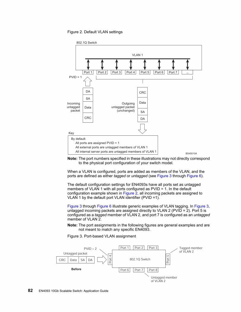
82 EN4093 10Gb Scalable Switch: Application Guide
Figure 2. Default VLAN settings
Note: The port numbers specified in these illustrations may not directly correspond to the physical port configuration of your switch model.
When a VLAN is configured, ports are added as members of the VLAN, and the ports are defined as either tagged or untagged (see Figure 3 through Figure 6).
The default configuration settings for EN4093s have all ports set as untagged members of VLAN 1 with all ports configured as PVID = 1. In the default configuration example shown in Figure 2, all incoming packets are assigned to VLAN 1 by the default port VLAN identifier (PVID =1).
Figure 3 through Figure 6 illustrate generic examples of VLAN tagging. In Figure 3, untagged incoming packets are assigned directly to VLAN 2 (PVID = 2). Port 5 is configured as a tagged member of VLAN 2, and port 7 is configured as an untagged member of VLAN 2.
Note: The port assignments in the following figures are general examples and are not meant to match any specific EN4093.
Figure 3. Port-based VLAN assignment
Port 1
DA
SA
Data
CRC
Incominguntagged
packet
BS45010A
Port 2 Port 3 Port 4 Port 5
VLAN 1
802.1Q Switch
By default:
Key
All ports are assigned PVID = 1
All external ports are untagged members of VLAN 1
All internal server ports are untagged members of VLAN 1
PVID = 1
Port 6 ...
DA
SA
Data
CRC
Outgoinguntagged packet
(unchanged)
Port 7
Port 6
DASADataCRC
Port 7 Port 8
Port 1
Por
t 4
Por
t 5
Port 2 Port 3
802.1Q Switch
PVID = 2
Untagged packet
Untagged memberof VLAN 2
Tagged memberof VLAN 2
Before
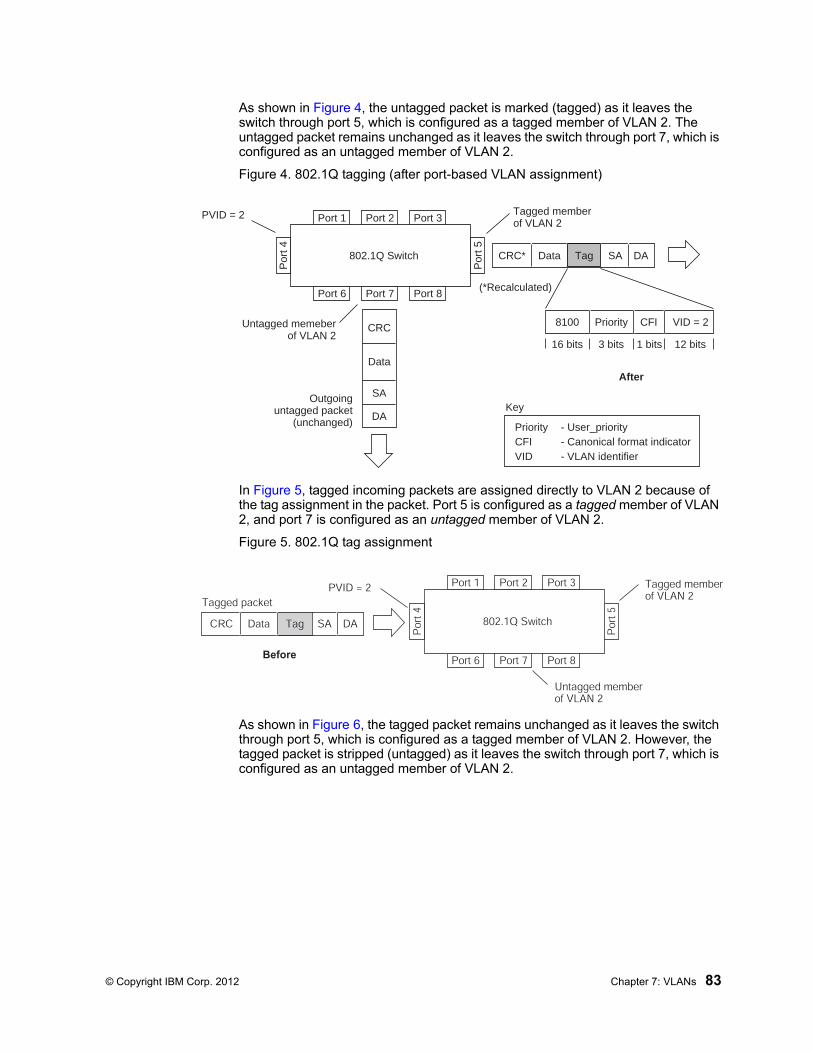
© Copyright IBM Corp. 2012 Chapter 7: VLANs 83
As shown in Figure 4, the untagged packet is marked (tagged) as it leaves the switch through port 5, which is configured as a tagged member of VLAN 2. The untagged packet remains unchanged as it leaves the switch through port 7, which is configured as an untagged member of VLAN 2.
Figure 4. 802.1Q tagging (after port-based VLAN assignment)
In Figure 5, tagged incoming packets are assigned directly to VLAN 2 because of the tag assignment in the packet. Port 5 is configured as a tagged member of VLAN 2, and port 7 is configured as an untagged member of VLAN 2.
Figure 5. 802.1Q tag assignment
As shown in Figure 6, the tagged packet remains unchanged as it leaves the switch through port 5, which is configured as a tagged member of VLAN 2. However, the tagged packet is stripped (untagged) as it leaves the switch through port 7, which is configured as an untagged member of VLAN 2.
Port 6 Port 7 Port 8
Port 1
Por
t 4
Por
t 5
Port 2 Port 3
802.1Q Switch
Key
PriorityCFI VID
- User_priority- Canonical format indicator- VLAN identifier
PVID = 2 Tagged memberof VLAN 2
Untagged memeberof VLAN 2
After
DA
SA
Data
CRC
(*Recalculated)
Outgoinguntagged packet
(unchanged)
DASADataCRC* Tag
VID = 2Priority
16 bits 3 bits 1 bits 12 bits
8100 CFI
Port 6
DASATagDataCRC
Tagged packet
Port 7 Port 8
Port 1
Por
t 4
Por
t 5
Port 2 Port 3
802.1Q Switch
PVID = 2
Untagged memberof VLAN 2
Tagged memberof VLAN 2
Before
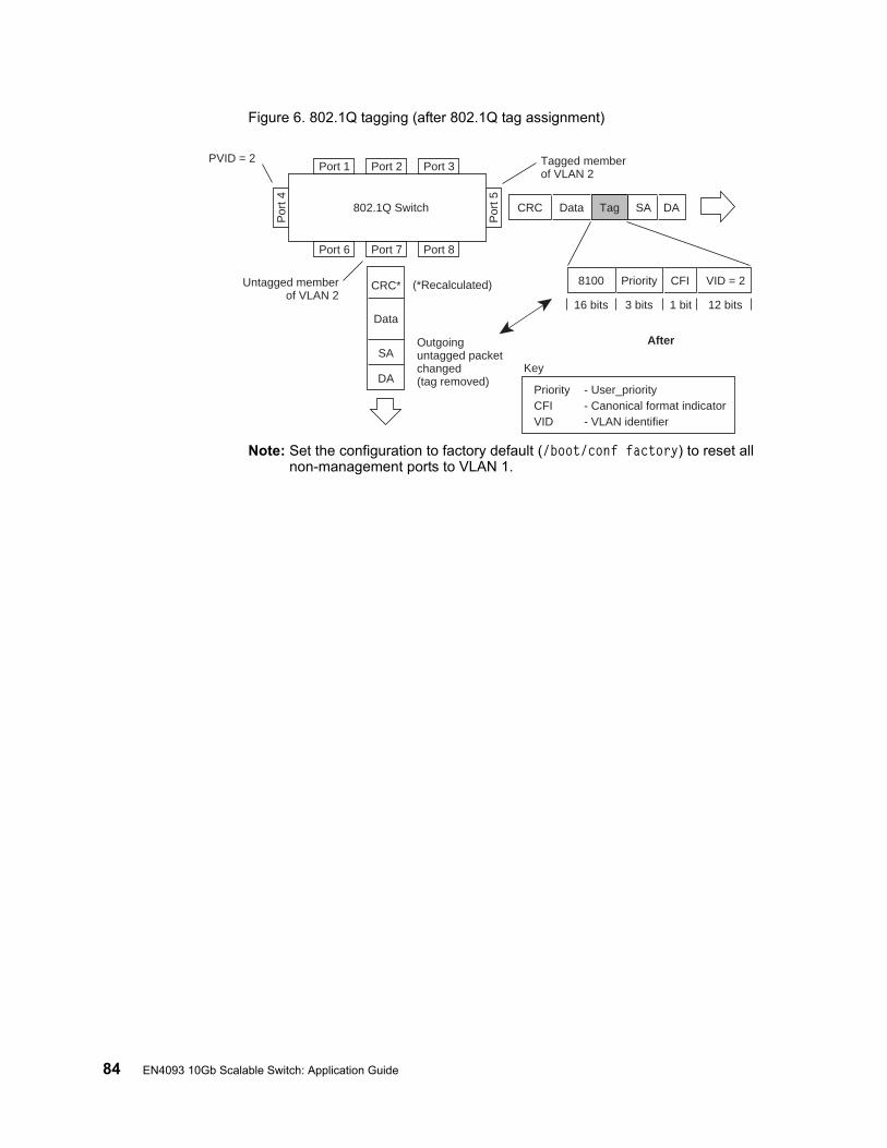
84 EN4093 10Gb Scalable Switch: Application Guide
Figure 6. 802.1Q tagging (after 802.1Q tag assignment)
Note: Set the configuration to factory default (/boot/conf factory) to reset all non-management ports to VLAN 1.
Port 6 Port 7 Port 8
Port 1
Por
t 4
Por
t 5
Port 2 Port 3
802.1Q Switch
Key
PriorityCFI VID
- User_priority- Canonical format indicator- VLAN identifier
PVID = 2 Tagged memberof VLAN 2
Untagged memberof VLAN 2
After
DA
SA
Data
CRC* (*Recalculated)
Outgoinguntagged packetchanged(tag removed)
DASADataCRC Tag
VID = 2Priority
16 bits 3 bits 1 bit 12 bits
8100 CFI
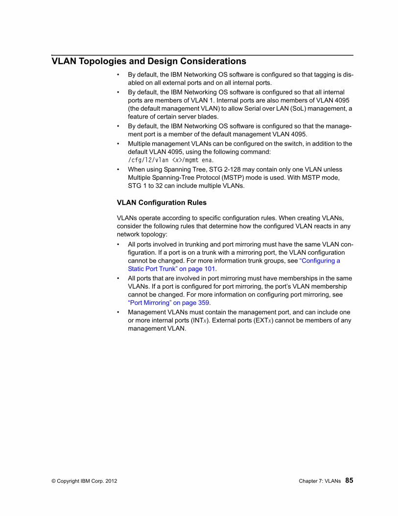
© Copyright IBM Corp. 2012 Chapter 7: VLANs 85
VLAN Topologies and Design Considerations• By default, the IBM Networking OS software is configured so that tagging is dis-
abled on all external ports and on all internal ports.
• By default, the IBM Networking OS software is configured so that all internal ports are members of VLAN 1. Internal ports are also members of VLAN 4095 (the default management VLAN) to allow Serial over LAN (SoL) management, a feature of certain server blades.
• By default, the IBM Networking OS software is configured so that the manage-ment port is a member of the default management VLAN 4095.
• Multiple management VLANs can be configured on the switch, in addition to the default VLAN 4095, using the following command: /cfg/l2/vlan <x>/mgmt ena.
• When using Spanning Tree, STG 2-128 may contain only one VLAN unless Multiple Spanning-Tree Protocol (MSTP) mode is used. With MSTP mode, STG 1 to 32 can include multiple VLANs.
VLAN Configuration Rules
VLANs operate according to specific configuration rules. When creating VLANs, consider the following rules that determine how the configured VLAN reacts in any network topology:
• All ports involved in trunking and port mirroring must have the same VLAN con-figuration. If a port is on a trunk with a mirroring port, the VLAN configuration cannot be changed. For more information trunk groups, see “Configuring a Static Port Trunk” on page 101.
• All ports that are involved in port mirroring must have memberships in the same VLANs. If a port is configured for port mirroring, the port’s VLAN membership cannot be changed. For more information on configuring port mirroring, see “Port Mirroring” on page 359.
• Management VLANs must contain the management port, and can include one or more internal ports (INTx). External ports (EXTx) cannot be members of any management VLAN.
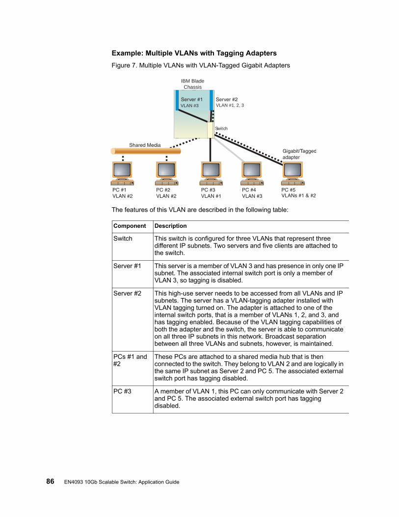
86 EN4093 10Gb Scalable Switch: Application Guide
Example: Multiple VLANs with Tagging Adapters
Figure 7. Multiple VLANs with VLAN-Tagged Gigabit Adapters
The features of this VLAN are described in the following table:
IBM BladeChassis
Switch
VLAN #1, 2, 3VLAN #3
Component Description
Switch This switch is configured for three VLANs that represent three different IP subnets. Two servers and five clients are attached to the switch.
Server #1 This server is a member of VLAN 3 and has presence in only one IP subnet. The associated internal switch port is only a member of VLAN 3, so tagging is disabled.
Server #2 This high-use server needs to be accessed from all VLANs and IP subnets. The server has a VLAN-tagging adapter installed with VLAN tagging turned on. The adapter is attached to one of the internal switch ports, that is a member of VLANs 1, 2, and 3, and has tagging enabled. Because of the VLAN tagging capabilities of both the adapter and the switch, the server is able to communicate on all three IP subnets in this network. Broadcast separation between all three VLANs and subnets, however, is maintained.
PCs #1 and #2
These PCs are attached to a shared media hub that is then connected to the switch. They belong to VLAN 2 and are logically in the same IP subnet as Server 2 and PC 5. The associated external switch port has tagging disabled.
PC #3 A member of VLAN 1, this PC can only communicate with Server 2 and PC 5. The associated external switch port has tagging disabled.
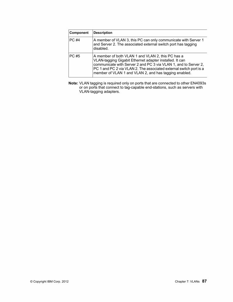
© Copyright IBM Corp. 2012 Chapter 7: VLANs 87
Note: VLAN tagging is required only on ports that are connected to other EN4093s or on ports that connect to tag-capable end-stations, such as servers with VLAN-tagging adapters.
PC #4 A member of VLAN 3, this PC can only communicate with Server 1 and Server 2. The associated external switch port has tagging disabled.
PC #5 A member of both VLAN 1 and VLAN 2, this PC has a VLAN-tagging Gigabit Ethernet adapter installed. It can communicate with Server 2 and PC 3 via VLAN 1, and to Server 2, PC 1 and PC 2 via VLAN 2. The associated external switch port is a member of VLAN 1 and VLAN 2, and has tagging enabled.
Component Description
88 EN4093 10Gb Scalable Switch: Application Guide
Protocol-Based VLANs
Protocol-based VLANs (PVLANs) allow you to segment network traffic according to the network protocols in use. Traffic for supported network protocols can be confined to a particular port-based VLAN. You can give different priority levels to traffic generated by different network protocols.
With PVLAN, the switch classifies incoming packets by Ethernet protocol of the packets, not by the configuration of the ingress port. When an untagged or priority-tagged frame arrives at an ingress port, the protocol information carried in the frame is used to determine a VLAN to which the frame belongs. If a frame’s protocol is not recognized as a pre-defined PVLAN type, the ingress port’s PVID is assigned to the frame. When a tagged frame arrives, the VLAN ID in the frame’s tag is used.
Each VLAN can contain up to eight different PVLANs. You can configure separate PVLANs on different VLANs, with each PVLAN segmenting traffic for the same protocol type. For example, you can configure PVLAN 1 on VLAN 2 to segment IPv4 traffic, and PVLAN 8 on VLAN 100 to segment IPv4 traffic.
To define a PVLAN on a VLAN, configure a PVLAN number (1-8) and specify the frame type and the Ethernet type of the PVLAN protocol. You must assign at least one port to the PVLAN before it can function. Define the PVLAN frame type and Ethernet type as follows:
• Frame type—consists of one of the following values:
– Ether2 (Ethernet II)
– SNAP (Subnetwork Access Protocol)
– LLC (Logical Link Control)
• Ethernet type—consists of a 4-digit (16 bit) hex value that defines the Ethernet type. You can use common Ethernet protocol values, or define your own values. Following are examples of common Ethernet protocol values:
– IPv4 = 0800– IPv6 = 86dd– ARP = 0806
Port-Based vs. Protocol-Based VLANs
Each VLAN supports both port-based and protocol-based association, as follows:
• The default VLAN configuration is port-based. All data ports are members of VLAN 1, with no PVLAN association.
• When you add ports to a PVLAN, the ports become members of both the port-based VLAN and the PVLAN. For example, if you add port EXT1 to PVLAN 1 on VLAN 2, the port also becomes a member of VLAN 2.
• When you delete a PVLAN, it’s member ports remain members of the port-based VLAN. For example, if you delete PVLAN 1 from VLAN 2, port EXT1 remains a member of VLAN 2.
• When you delete a port from a VLAN, the port is deleted from all corresponding PVLANs.
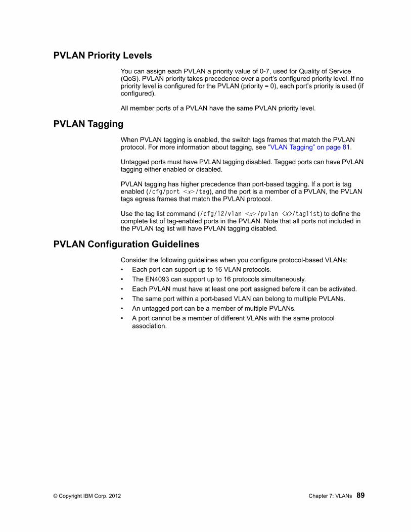
© Copyright IBM Corp. 2012 Chapter 7: VLANs 89
PVLAN Priority Levels
You can assign each PVLAN a priority value of 0-7, used for Quality of Service (QoS). PVLAN priority takes precedence over a port’s configured priority level. If no priority level is configured for the PVLAN (priority = 0), each port’s priority is used (if configured).
All member ports of a PVLAN have the same PVLAN priority level.
PVLAN Tagging
When PVLAN tagging is enabled, the switch tags frames that match the PVLAN protocol. For more information about tagging, see “VLAN Tagging” on page 81.
Untagged ports must have PVLAN tagging disabled. Tagged ports can have PVLAN tagging either enabled or disabled.
PVLAN tagging has higher precedence than port-based tagging. If a port is tag enabled (/cfg/port <x>/tag), and the port is a member of a PVLAN, the PVLAN tags egress frames that match the PVLAN protocol.
Use the tag list command (/cfg/l2/vlan <x>/pvlan <x>/taglist) to define the complete list of tag-enabled ports in the PVLAN. Note that all ports not included in the PVLAN tag list will have PVLAN tagging disabled.
PVLAN Configuration Guidelines
Consider the following guidelines when you configure protocol-based VLANs:
• Each port can support up to 16 VLAN protocols.
• The EN4093 can support up to 16 protocols simultaneously.
• Each PVLAN must have at least one port assigned before it can be activated.
• The same port within a port-based VLAN can belong to multiple PVLANs.
• An untagged port can be a member of multiple PVLANs.
• A port cannot be a member of different VLANs with the same protocol association.
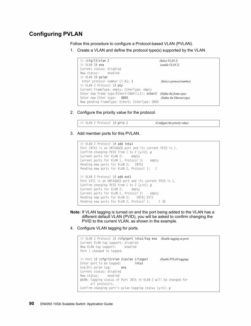
90 EN4093 10Gb Scalable Switch: Application Guide
Configuring PVLAN
Follow this procedure to configure a Protocol-based VLAN (PVLAN).
1. Create a VLAN and define the protocol type(s) supported by the VLAN.
2. Configure the priority value for the protocol.
3. Add member ports for this PVLAN.
Note: If VLAN tagging is turned on and the port being added to the VLAN has a different default VLAN (PVID), you will be asked to confirm changing the PVID to the current VLAN, as shown in the example.
4. Configure VLAN tagging for ports.
>> /cfg/l2/vlan 2 (Select VLAN 2)>> VLAN 2# ena (enable VLAN 2)Current status: disabledNew status: enabled>> VLAN 2# pvlan Enter protocol number [1-8]: 1 (Select a protocol number)>> VLAN 2 Protocol 1# ptyCurrent FrameType: empty; EtherType: emptyEnter new frame type(Ether2/SNAP/LLC): ether2 (Define the frame type)Enter new Ether type: 0800 (Define the Ethernet type)New pending FrameType: Ether2; EtherType: 0800
>> VLAN 2 Protocol 1# prio 1 (Configure the priority value)
>> VLAN 2 Protocol 1# add inta1Port INTA1 is an UNTAGGED port and its current PVID is 1.Confirm changing PVID from 1 to 2 [y/n]: yCurrent ports for VLAN 2: emptyCurrent ports for VLAN 1, Protocol 3: emptyPending new ports for VLAN 2: INTA1Pending new ports for VLAN 2, Protocol 1: 1
>> VLAN 2 Protocol 1# add ext1Port EXT1 is an UNTAGGED port and its current PVID is 1.Confirm changing PVID from 1 to 2 [y/n]: yCurrent ports for VLAN 2: emptyCurrent ports for VLAN 1, Protocol 2: emptyPending new ports for VLAN 2: INTA1 EXT1Pending new ports for VLAN 2, Protocol 1: 1 38
>> VLAN 2 Protocol 1# /cfg/port inta1/tag ena (Enable tagging on port)Current VLAN tag support: disabledNew VLAN tag support: enabledPort 1 changed to tagged.
>> Port 1# /cfg/l2/vlan 2/pvlan 1/tagpvl (Enable PVLAN tagging)Enter port to be tagged: inta1Ena/Dis pvlan tag: enaCurrent status: disabledNew status: enabledWARN: Tagging status of Port INTA in VLAN 2 will be changed for all protocols.Confirm changing port's pvlan tagging status [y/n]: y
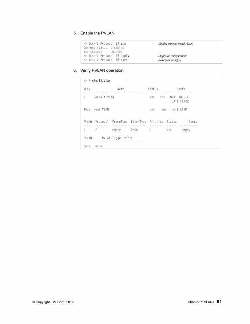
© Copyright IBM Corp. 2012 Chapter 7: VLANs 91
5. Enable the PVLAN.
6. Verify PVLAN operation.
>> VLAN 2 Protocol 1# ena (Enable protocol-based VLAN)Current status: disabledNew status: enabled>> VLAN 2 Protocol 1# apply (Apply the configuration)>> VLAN 2 Protocol 1# save (Save your changes)
>> /info/l2/vlan
VLAN Name Status Ports---- ------------------------------ ------ --------------------1 Default VLAN ena dis INTA1-INTB14 EXT1-EXT22
4095 Mgmt VLAN ena ena MGT1 EXTM
PVLAN Protocol FrameType EtherType Priority Status Ports----- -------- -------------------- -------- ------ -----------1 2 empty 0800 0 dis empty
PVLAN PVLAN-Tagged Ports----- ---------------------------none none
92 EN4093 10Gb Scalable Switch: Application Guide
Private VLANs
Private VLANs provide Layer 2 isolation between the ports within the same broadcast domain. Private VLANs can control traffic within a VLAN domain, and provide port-based security for host servers.
Use Private VLANs to partition a VLAN domain into sub-domains. Each sub-domain is comprised of one primary VLAN and one secondary VLAN, as follows:
• Primary VLAN—carries unidirectional traffic downstream from promiscuous ports. Each Private VLAN has only one primary VLAN. All ports in the Private VLAN are members of the primary VLAN.
• Secondary VLAN—Secondary VLANs are internal to a private VLAN domain, and are defined as follows:
– Isolated VLAN—carries unidirectional traffic upstream from the host servers toward ports in the primary VLAN and the gateway. Each Private VLAN can contain only one Isolated VLAN.
– Community VLAN—carries upstream traffic from ports in the community VLAN to other ports in the same community, and to ports in the primary VLAN and the gateway. Each Private VLAN can contain multiple community VLANs.
After you define the primary VLAN and one or more secondary VLANs, you map the secondary VLAN(s) to the primary VLAN.
Private VLAN Ports
Private VLAN ports are defined as follows:
• Promiscuous—A promiscuous port is an external port that belongs to the primary VLAN. The promiscuous port can communicate with all the interfaces, including ports in the secondary VLANs (Isolated VLAN and Community VLANs). Each promiscuous port can belong to only one Private VLAN.
• Isolated—An isolated port is a host port that belongs to an isolated VLAN. Each isolated port has complete layer 2 separation from other ports within the same private VLAN (including other isolated ports), except for the promiscuous ports.
– Traffic sent to an isolated port is blocked by the Private VLAN, except the traffic from promiscuous ports.
– Traffic received from an isolated port is forwarded only to promiscuous ports.
• Community—A community port is a host port that belongs to a community VLAN. Community ports can communicate with other ports in the same community VLAN, and with promiscuous ports. These interfaces are isolated at layer 2 from all other interfaces in other communities and from isolated ports within the Private VLAN.
Only external ports are promiscuous ports. Only internal ports may be isolated or community ports.
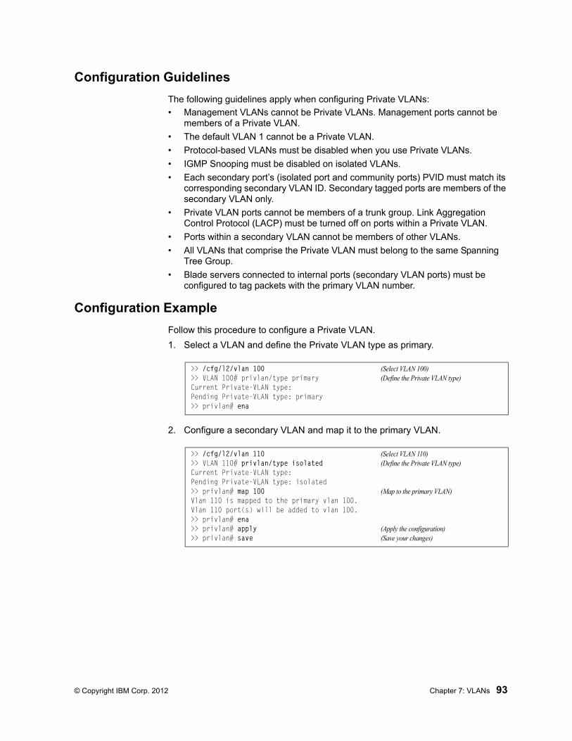
© Copyright IBM Corp. 2012 Chapter 7: VLANs 93
Configuration Guidelines
The following guidelines apply when configuring Private VLANs:
• Management VLANs cannot be Private VLANs. Management ports cannot be members of a Private VLAN.
• The default VLAN 1 cannot be a Private VLAN.
• Protocol-based VLANs must be disabled when you use Private VLANs.
• IGMP Snooping must be disabled on isolated VLANs.
• Each secondary port’s (isolated port and community ports) PVID must match its corresponding secondary VLAN ID. Secondary tagged ports are members of the secondary VLAN only.
• Private VLAN ports cannot be members of a trunk group. Link Aggregation Control Protocol (LACP) must be turned off on ports within a Private VLAN.
• Ports within a secondary VLAN cannot be members of other VLANs.
• All VLANs that comprise the Private VLAN must belong to the same Spanning Tree Group.
• Blade servers connected to internal ports (secondary VLAN ports) must be configured to tag packets with the primary VLAN number.
Configuration Example
Follow this procedure to configure a Private VLAN.
1. Select a VLAN and define the Private VLAN type as primary.
2. Configure a secondary VLAN and map it to the primary VLAN.
>> /cfg/l2/vlan 100 (Select VLAN 100)>> VLAN 100# privlan/type primary (Define the Private VLAN type)Current Private-VLAN type:Pending Private-VLAN type: primary>> privlan# ena
>> /cfg/l2/vlan 110 (Select VLAN 110)>> VLAN 110# privlan/type isolated (Define the Private VLAN type)Current Private-VLAN type:Pending Private-VLAN type: isolated>> privlan# map 100 (Map to the primary VLAN)Vlan 110 is mapped to the primary vlan 100.Vlan 110 port(s) will be added to vlan 100.>> privlan# ena>> privlan# apply (Apply the configuration)>> privlan# save (Save your changes)

94 EN4093 10Gb Scalable Switch: Application Guide

© Copyright IBM Corp. 2012 95
Chapter 8. Ports and Trunking
Trunk groups can provide super-bandwidth, multi-link connections between the EN4093 10Gb Scalable Switch (EN4093) and other trunk-capable devices. A trunk group is a group of ports that act together, combining their bandwidth to create a single, larger virtual link. This chapter provides configuration background and examples for trunking multiple ports together:
• “Configuring Port Modes” on page 96
• “Configuring QSFP+ Ports” on page 98
• “Trunking Overview” on page 99
• “Static Trunks” on page 100
• “Configurable Trunk Hash Algorithm” on page 103
• “Link Aggregation Control Protocol” on page 105

96 EN4093 10Gb Scalable Switch: Application Guide
Configuring Port Modes
The switch allows you to set the port mode. Select the port mode that fits your network configuration.
The following port modes are available:
• Base Port mode:
– Fourteen 10Gb internal (1 port x 14 blade servers)
– Ten 10Gb external
• 44 Port mode:
– Twenty Eight 10Gb internal (2 port x 14 blade servers)
– Twelve 10Gb external
– One 40Gb external
• 64 Port mode:
– Forty Two 10Gb internal (3 ports x 14 Blade servers)
– Fourteen 10Gb external
– Two 40Gb external
Base Port mode is the default. To upgrade the port mode, you must obtain a software license key.
Use the following command to enter the software license key to upgrade the port mode:
Note: You must upgrade to 44Port mode before you can upgrade to 64Port mode.
After you enter the license key, you must reset the switch (/boot/reset) for the change to take affect. Use the following command to verify the port configuration:
>> Main# /oper/swkey/fodkey/enakey
Enter The Software Feature: 44PortEnter License Key:

© Copyright IBM Corp. 2012 Chapter 8: Ports and Trunking 97
>> Boot Options# /info/port
Alias Port Tag RMON Lrn Fld PVID NAME VLAN(s)------- ---- --- ---- --- --- ----- -------------- -------------------------------INTA1 1 n d e e 1 INTA1 1INTA2 2 n d e e 1 INTA2 1INTA3 3 n d e e 1 INTA3 1INTA4 4 n d e e 1 INTA4 1INTA5 5 n d e e 1 INTA5 1INTA6 6 n d e e 1 INTA6 1INTA7 7 n d e e 1 INTA7 1INTA8 8 n d e e 1 INTA8 1INTA9 9 n d e e 1 INTA9 1INTA10 10 n d e e 1 INTA10 1INTA11 11 n d e e 1 INTA11 1INTA12 12 n d e e 1 INTA12 1INTA13 13 n d e e 1 INTA13 1INTA14 14 n d e e 1 INTA14 1INTB1 15 n d e e 1 INTB1 1INTB2 16 n d e e 1 INTB2 1...EXT20 62 n d e e 1 EXT20 1EXT21 63 n d e e 1 EXT21 1EXT22 64 n d e e 1 EXT22 1EXTM 65 n d e e 4095 EXTM 4095MGT1 66 y d e e 4095 MGT1 4095
* = PVID is tagged.
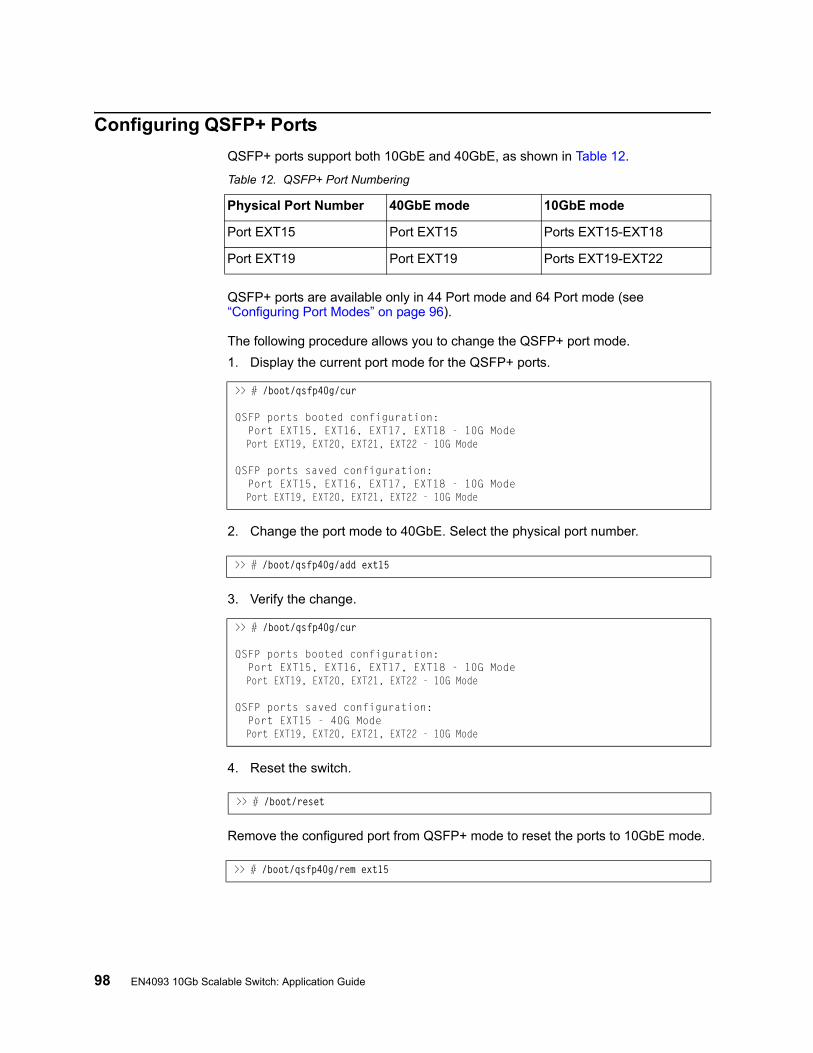
98 EN4093 10Gb Scalable Switch: Application Guide
Configuring QSFP+ Ports
QSFP+ ports support both 10GbE and 40GbE, as shown in Table 12.
Table 12. QSFP+ Port Numbering
QSFP+ ports are available only in 44 Port mode and 64 Port mode (see “Configuring Port Modes” on page 96).
The following procedure allows you to change the QSFP+ port mode.
1. Display the current port mode for the QSFP+ ports.
2. Change the port mode to 40GbE. Select the physical port number.
3. Verify the change.
4. Reset the switch.
Remove the configured port from QSFP+ mode to reset the ports to 10GbE mode.
Physical Port Number 40GbE mode 10GbE mode
Port EXT15 Port EXT15 Ports EXT15-EXT18
Port EXT19 Port EXT19 Ports EXT19-EXT22
>> # /boot/qsfp40g/cur
QSFP ports booted configuration: Port EXT15, EXT16, EXT17, EXT18 - 10G Mode Port EXT19, EXT20, EXT21, EXT22 - 10G Mode
QSFP ports saved configuration: Port EXT15, EXT16, EXT17, EXT18 - 10G Mode Port EXT19, EXT20, EXT21, EXT22 - 10G Mode
>> # /boot/qsfp40g/add ext15
>> # /boot/qsfp40g/cur
QSFP ports booted configuration: Port EXT15, EXT16, EXT17, EXT18 - 10G Mode Port EXT19, EXT20, EXT21, EXT22 - 10G Mode
QSFP ports saved configuration: Port EXT15 - 40G Mode Port EXT19, EXT20, EXT21, EXT22 - 10G Mode
>> # /boot/reset
>> # /boot/qsfp40g/rem ext15
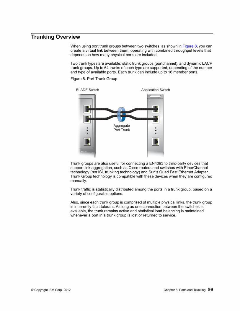
© Copyright IBM Corp. 2012 Chapter 8: Ports and Trunking 99
Trunking Overview
When using port trunk groups between two switches, as shown in Figure 8, you can create a virtual link between them, operating with combined throughput levels that depends on how many physical ports are included.
Two trunk types are available: static trunk groups (portchannel), and dynamic LACP trunk groups. Up to 64 trunks of each type are supported, depending of the number and type of available ports. Each trunk can include up to 16 member ports.
Figure 8. Port Trunk Group
Trunk groups are also useful for connecting a EN4093 to third-party devices that support link aggregation, such as Cisco routers and switches with EtherChannel technology (not ISL trunking technology) and Sun's Quad Fast Ethernet Adapter. Trunk Group technology is compatible with these devices when they are configured manually.
Trunk traffic is statistically distributed among the ports in a trunk group, based on a variety of configurable options.
Also, since each trunk group is comprised of multiple physical links, the trunk group is inherently fault tolerant. As long as one connection between the switches is available, the trunk remains active and statistical load balancing is maintained whenever a port in a trunk group is lost or returned to service.
Application Switch
AggregatePort Trunk
BLADE Switch
100 EN4093 10Gb Scalable Switch: Application Guide
Static Trunks
Before Configuring Static Trunks
When you create and enable a static trunk, the trunk members (switch ports) take on certain settings necessary for correct operation of the trunking feature.
Before you configure your trunk, you must consider these settings, along with specific configuration rules, as follows:
• Read the configuration rules provided in the section, “Static Trunk Group Configuration Rules” on page 100.”
• Determine which switch ports are to become trunk members (the specific ports making up the trunk).
• Ensure that the chosen switch ports are set to enabled, using the following command: /cfg/port/ena
• Ensure all member ports in a trunk have the same VLAN configuration.
• Consider how the existing Spanning Tree will react to the new trunk configuration. See “Spanning Tree Protocols” on page 109 for configuration guidelines.
• Consider how existing VLANs will be affected by the addition of a trunk.
Static Trunk Group Configuration Rules
The trunking feature operates according to specific configuration rules. When creating trunks, consider the following rules that determine how a trunk group reacts in any network topology:
• All trunks must originate from one network entity (a single device, or multiple devices acting in a stack) and lead to one destination entity. For example, you cannot combine links from two different servers into one trunk group.
• Any physical switch port can belong to only one trunk group.
• Depending on port availability, the switch supports up to 16 ports in each trunk group.
• Internal ports (INTx) and external ports (EXTx) cannot become members of the same trunk group.
• Trunking from third-party devices must comply with Cisco® EtherChannel® technology.
• All trunk member ports must be assigned to the same VLAN configuration before the trunk can be enabled.
• If you change the VLAN settings of any trunk member, you cannot apply the change until you change the VLAN settings of all trunk members.
• When an active port is configured in a trunk, the port becomes a trunk member when you enable the trunk using the following command: /cfg/l2/trunk <x>/enaThe Spanning Tree parameters for the port then change to reflect the new trunk settings.
• All trunk members must be in the same Spanning Tree Group (STG) and can belong to only one Spanning Tree Group (STG). However if all ports are tagged, then all trunk ports can belong to multiple STGs.
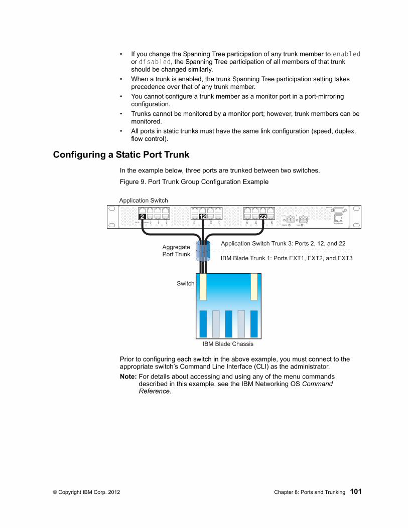
© Copyright IBM Corp. 2012 Chapter 8: Ports and Trunking 101
• If you change the Spanning Tree participation of any trunk member to enabled or disabled, the Spanning Tree participation of all members of that trunk should be changed similarly.
• When a trunk is enabled, the trunk Spanning Tree participation setting takes precedence over that of any trunk member.
• You cannot configure a trunk member as a monitor port in a port-mirroring configuration.
• Trunks cannot be monitored by a monitor port; however, trunk members can be monitored.
• All ports in static trunks must have the same link configuration (speed, duplex, flow control).
Configuring a Static Port Trunk
In the example below, three ports are trunked between two switches.
Figure 9. Port Trunk Group Configuration Example
Prior to configuring each switch in the above example, you must connect to the appropriate switch’s Command Line Interface (CLI) as the administrator.
Note: For details about accessing and using any of the menu commands described in this example, see the IBM Networking OS Command Reference.
Application Switch
IBM Blade Chassis
Switch
Application Switch Trunk 3: Ports 2, 12, and 22
IBM Blade Trunk 1: Ports EXT1, EXT2, and EXT3
AggregatePort Trunk

102 EN4093 10Gb Scalable Switch: Application Guide
1. Connect the switch ports that will be members in the trunk group.
2. Configure the trunk using these steps on the EN4093:
a. Define a trunk group.
b. Apply and verify the configuration.
Examine the resulting information. If any settings are incorrect, make appropriate changes.
c. Save your new configuration changes.
3. Repeat the process on the other switch.
Trunk group 1 (on the EN4093) is now connected to trunk group 3 on the Application Switch.
Note: In this example, a EN4093 and an application switch are used. If a third-party device supporting link aggregation is used (such as Cisco routers and switches with EtherChannel technology or Sun's Quad Fast Ethernet Adapter), trunk groups on the third-party device should be configured manually. Connection problems could arise when using automatic trunk group negotiation on the third-party device.
4. Examine the trunking information on each switch.
Information about each port in each configured trunk group is displayed. Make sure that trunk groups consist of the expected ports and that each port is in the expected state.
>> # /cfg/l2/trunk 1 (Select trunk group 1)
>> Trunk group 1# add EXT1 (Add port EXT1 to trunk group 1)
>> Trunk group 1# add EXT2 (Add port EXT2 to trunk group 1)
>> Trunk group 1# add EXT3 (Add port EXT3 to trunk group 1)
>> Trunk group 1# ena (Enable trunk group 1)
>> Trunk group 1# apply (Make your changes active)
>> Trunk group 1# cur (View current trunking configuration)
>> Trunk group 1# save (Save for restore after reboot)
>> # /cfg/l2/trunk 3 (Select trunk group 3)
>> Trunk group 3# add 2 (Add port 2 to trunk group 3)
>> Trunk group 3# add 12 (Add port 12 to trunk group 3)
>> Trunk group 3# add 22 (Add port 22 to trunk group 3)
>> Trunk group 3# ena (Enable trunk group 3)
>> Trunk group 3# apply (Make your changes active)
>> Trunk group 3# cur (View current trunking configuration)
>> Trunk group 3# save (Save for restore after reboot)
>> /info/l2/trunk (View trunking information)
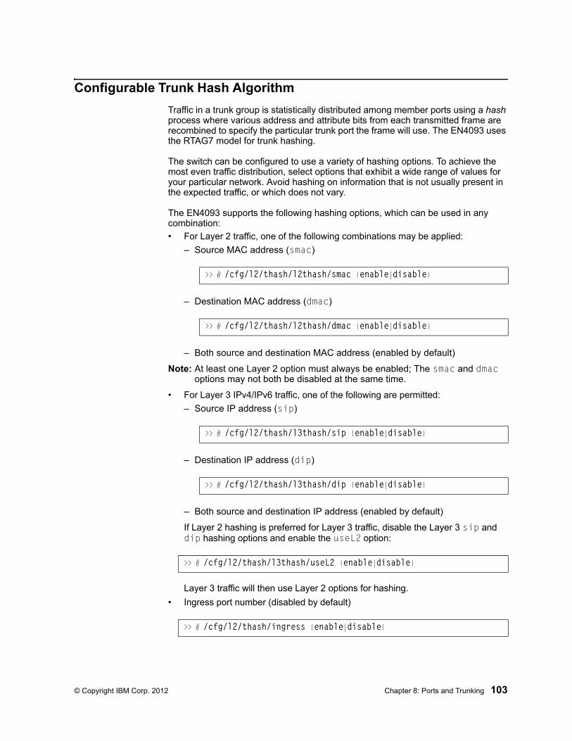
© Copyright IBM Corp. 2012 Chapter 8: Ports and Trunking 103
Configurable Trunk Hash Algorithm
Traffic in a trunk group is statistically distributed among member ports using a hash process where various address and attribute bits from each transmitted frame are recombined to specify the particular trunk port the frame will use. The EN4093 uses the RTAG7 model for trunk hashing.
The switch can be configured to use a variety of hashing options. To achieve the most even traffic distribution, select options that exhibit a wide range of values for your particular network. Avoid hashing on information that is not usually present in the expected traffic, or which does not vary.
The EN4093 supports the following hashing options, which can be used in any combination:
• For Layer 2 traffic, one of the following combinations may be applied:
– Source MAC address (smac)
– Destination MAC address (dmac)
– Both source and destination MAC address (enabled by default)
Note: At least one Layer 2 option must always be enabled; The smac and dmac options may not both be disabled at the same time.
• For Layer 3 IPv4/IPv6 traffic, one of the following are permitted:
– Source IP address (sip)
– Destination IP address (dip)
– Both source and destination IP address (enabled by default)
If Layer 2 hashing is preferred for Layer 3 traffic, disable the Layer 3 sip and dip hashing options and enable the useL2 option:
Layer 3 traffic will then use Layer 2 options for hashing.
• Ingress port number (disabled by default)
>> # /cfg/l2/thash/l2thash/smac {enable|disable}
>> # /cfg/l2/thash/l2thash/dmac {enable|disable}
>> # /cfg/l2/thash/l3thash/sip {enable|disable}
>> # /cfg/l2/thash/l3thash/dip {enable|disable}
>> # /cfg/l2/thash/l3thash/useL2 {enable|disable}
>> # /cfg/l2/thash/ingress {enable|disable}

104 EN4093 10Gb Scalable Switch: Application Guide
• Layer 4 port information (disabled by default)
When enabled, Layer 4 port information (TCP, UPD, etc.) is added to the hash if available. The L4port option is ignored when Layer 4 information is not included in the packet (such as for Layer 2 packets), or when the useL2 option is enabled.
Note: For MPLS packets, Layer 4 port information is excluded from the hash calculation. Instead, other IP fields are used, along with the first two MPLS labels.
>> # /cfg/l2/thash/L4port {enable|disable}
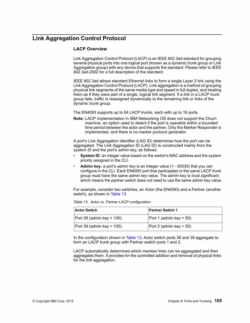
© Copyright IBM Corp. 2012 Chapter 8: Ports and Trunking 105
Link Aggregation Control Protocol
LACP Overview
Link Aggregation Control Protocol (LACP) is an IEEE 802.3ad standard for grouping several physical ports into one logical port (known as a dynamic trunk group or Link Aggregation group) with any device that supports the standard. Please refer to IEEE 802.3ad-2002 for a full description of the standard.
IEEE 802.3ad allows standard Ethernet links to form a single Layer 2 link using the Link Aggregation Control Protocol (LACP). Link aggregation is a method of grouping physical link segments of the same media type and speed in full duplex, and treating them as if they were part of a single, logical link segment. If a link in a LACP trunk group fails, traffic is reassigned dynamically to the remaining link or links of the dynamic trunk group.
The EN4093 supports up to 64 LACP trunks, each with up to 16 ports.
Note: LACP implementation in IBM Networking OS does not support the Churn machine, an option used to detect if the port is operable within a bounded time period between the actor and the partner. Only the Marker Responder is implemented, and there is no marker protocol generator.
A port’s Link Aggregation Identifier (LAG ID) determines how the port can be aggregated. The Link Aggregation ID (LAG ID) is constructed mainly from the system ID and the port’s admin key, as follows:
• System ID: an integer value based on the switch’s MAC address and the system priority assigned in the CLI.
• Admin key: a port’s admin key is an integer value (1 - 65535) that you can configure in the CLI. Each EN4093 port that participates in the same LACP trunk group must have the same admin key value. The admin key is local significant, which means the partner switch does not need to use the same admin key value.
For example, consider two switches, an Actor (the EN4093) and a Partner (another switch), as shown in Table 13.
In the configuration shown in Table 13, Actor switch ports 38 and 39 aggregate to form an LACP trunk group with Partner switch ports 1 and 2.
LACP automatically determines which member links can be aggregated and then aggregates them. It provides for the controlled addition and removal of physical links for the link aggregation.
Table 13. Actor vs. Partner LACP configuration
Actor Switch Partner Switch 1
Port 38 (admin key = 100) Port 1 (admin key = 50)
Port 39 (admin key = 100) Port 2 (admin key = 50)
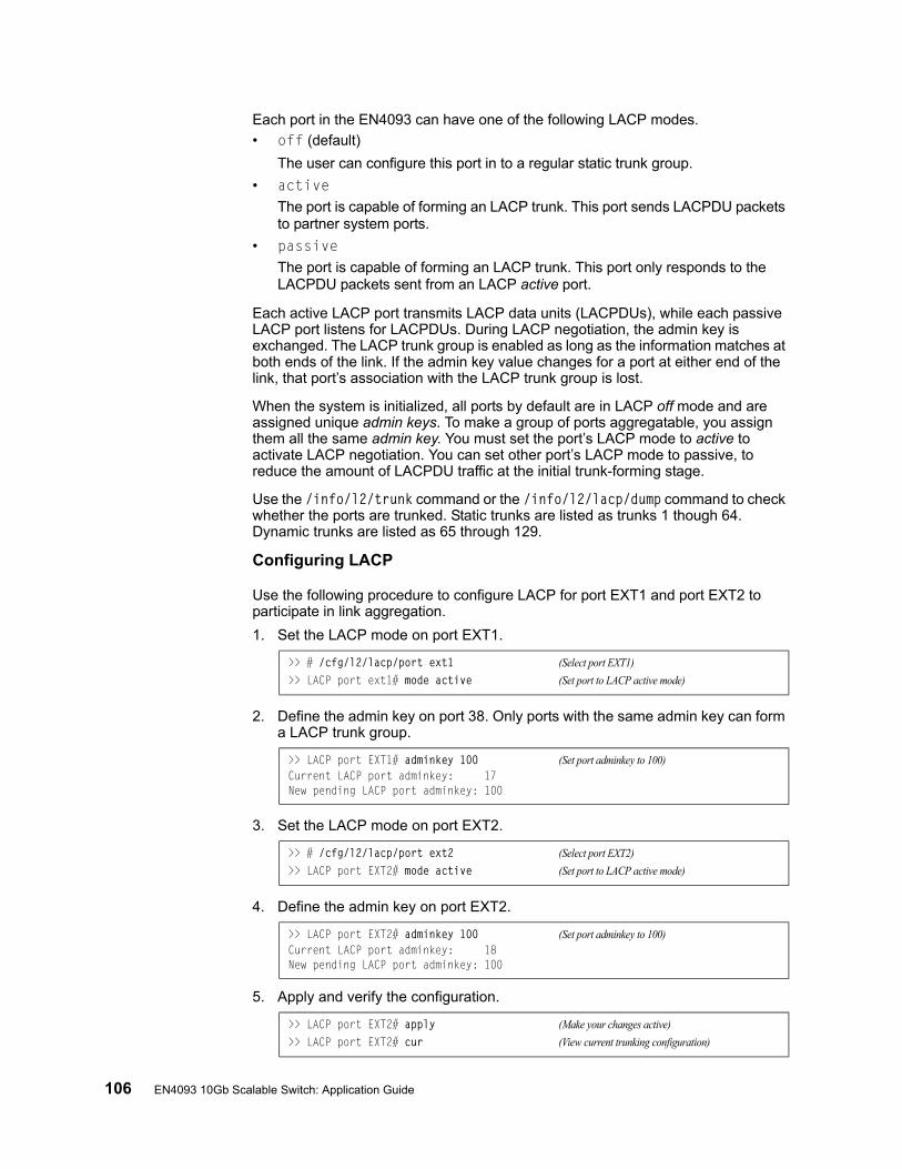
106 EN4093 10Gb Scalable Switch: Application Guide
Each port in the EN4093 can have one of the following LACP modes.
• off (default)
The user can configure this port in to a regular static trunk group.
• activeThe port is capable of forming an LACP trunk. This port sends LACPDU packets to partner system ports.
• passiveThe port is capable of forming an LACP trunk. This port only responds to the LACPDU packets sent from an LACP active port.
Each active LACP port transmits LACP data units (LACPDUs), while each passive LACP port listens for LACPDUs. During LACP negotiation, the admin key is exchanged. The LACP trunk group is enabled as long as the information matches at both ends of the link. If the admin key value changes for a port at either end of the link, that port’s association with the LACP trunk group is lost.
When the system is initialized, all ports by default are in LACP off mode and are assigned unique admin keys. To make a group of ports aggregatable, you assign them all the same admin key. You must set the port’s LACP mode to active to activate LACP negotiation. You can set other port’s LACP mode to passive, to reduce the amount of LACPDU traffic at the initial trunk-forming stage.
Use the /info/l2/trunk command or the /info/l2/lacp/dump command to check whether the ports are trunked. Static trunks are listed as trunks 1 though 64. Dynamic trunks are listed as 65 through 129.
Configuring LACP
Use the following procedure to configure LACP for port EXT1 and port EXT2 to participate in link aggregation.
1. Set the LACP mode on port EXT1.
2. Define the admin key on port 38. Only ports with the same admin key can form a LACP trunk group.
3. Set the LACP mode on port EXT2.
4. Define the admin key on port EXT2.
5. Apply and verify the configuration.
>> # /cfg/l2/lacp/port ext1 (Select port EXT1)
>> LACP port ext1# mode active (Set port to LACP active mode)
>> LACP port EXT1# adminkey 100 (Set port adminkey to 100)Current LACP port adminkey: 17New pending LACP port adminkey: 100
>> # /cfg/l2/lacp/port ext2 (Select port EXT2)
>> LACP port EXT2# mode active (Set port to LACP active mode)
>> LACP port EXT2# adminkey 100 (Set port adminkey to 100)Current LACP port adminkey: 18New pending LACP port adminkey: 100
>> LACP port EXT2# apply (Make your changes active)
>> LACP port EXT2# cur (View current trunking configuration)

© Copyright IBM Corp. 2012 Chapter 8: Ports and Trunking 107
6. Save your new configuration changes.
>> LACP port EXT2# save (Save for restore after reboot)

108 EN4093 10Gb Scalable Switch: Application Guide
© Copyright IBM Corp. 2012 109
Chapter 9. Spanning Tree Protocols
When multiple paths exist between two points on a network, Spanning Tree Protocol (STP), or one of its enhanced variants, can prevent broadcast loops and ensure that the EN4093 10Gb Scalable Switch (EN4093) uses only the most efficient network path.
This chapter covers the following topics:
• “Spanning Tree Protocol Modes” on page 109
• “Global STP Control” on page 110
• “PVSRT Mode” on page 110
• “Rapid Spanning Tree Protocol” on page 121
• “Multiple Spanning Tree Protocol” on page 123
• “Port Type and Link Type” on page 127
Spanning Tree Protocol Modes
IBM Networking OS 7.2 supports the following STP modes:
• Rapid Spanning Tree Protocol (RSTP)
IEEE 802.1D (2004) RSTP allows devices to detect and eliminate logical loops in a bridged or switched network. When multiple paths exist, STP configures the network so that only the most efficient path is used. If that path fails, STP automatically configures the best alternative active path on the network in order to sustain network operations. RSTP is an enhanced version of IEEE 802.1D (1998) STP, providing more rapid convergence of the Spanning Tree network path states on STG 1.
See “Rapid Spanning Tree Protocol” on page 121 for details.
• Per-VLAN Rapid Spanning Tree (PVRST+)
PVRST mode is based on RSTP to provide rapid Spanning Tree convergence, but supports instances of Spanning Tree, allowing one STG per VLAN. PVRST mode is compatible with Cisco R-PVST/R-PVST+ mode.
PVRST is the default Spanning Tree mode on the EN4093. See “PVSRT Mode” on page 110 for details.
• Multiple Spanning Tree Protocol (MSTP)
IEEE 802.1Q (2003) MSTP provides both rapid convergence and load balancing in a VLAN environment. MSTP allows multiple STGs, with multiple VLANs in each.
MSTP is supported in stand-alone (non-stacking) mode only.
See “Multiple Spanning Tree Protocol” on page 123 for details.
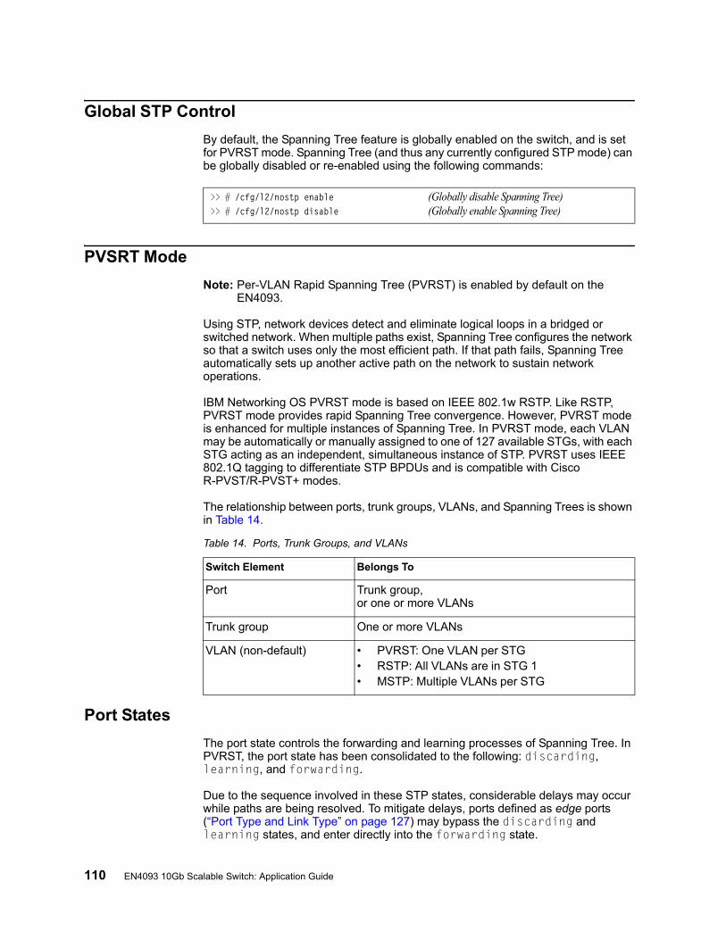
110 EN4093 10Gb Scalable Switch: Application Guide
Global STP Control
By default, the Spanning Tree feature is globally enabled on the switch, and is set for PVRST mode. Spanning Tree (and thus any currently configured STP mode) can be globally disabled or re-enabled using the following commands:
PVSRT Mode
Note: Per-VLAN Rapid Spanning Tree (PVRST) is enabled by default on the EN4093.
Using STP, network devices detect and eliminate logical loops in a bridged or switched network. When multiple paths exist, Spanning Tree configures the network so that a switch uses only the most efficient path. If that path fails, Spanning Tree automatically sets up another active path on the network to sustain network operations.
IBM Networking OS PVRST mode is based on IEEE 802.1w RSTP. Like RSTP, PVRST mode provides rapid Spanning Tree convergence. However, PVRST mode is enhanced for multiple instances of Spanning Tree. In PVRST mode, each VLAN may be automatically or manually assigned to one of 127 available STGs, with each STG acting as an independent, simultaneous instance of STP. PVRST uses IEEE 802.1Q tagging to differentiate STP BPDUs and is compatible with Cisco R-PVST/R-PVST+ modes.
The relationship between ports, trunk groups, VLANs, and Spanning Trees is shown in Table 14.
Port States
The port state controls the forwarding and learning processes of Spanning Tree. In PVRST, the port state has been consolidated to the following: discarding, learning, and forwarding.
Due to the sequence involved in these STP states, considerable delays may occur while paths are being resolved. To mitigate delays, ports defined as edge ports (“Port Type and Link Type” on page 127) may bypass the discarding and learning states, and enter directly into the forwarding state.
>> # /cfg/l2/nostp enable (Globally disable Spanning Tree)>> # /cfg/l2/nostp disable (Globally enable Spanning Tree)
Table 14. Ports, Trunk Groups, and VLANs
Switch Element Belongs To
Port Trunk group, or one or more VLANs
Trunk group One or more VLANs
VLAN (non-default) • PVRST: One VLAN per STG• RSTP: All VLANs are in STG 1• MSTP: Multiple VLANs per STG
© Copyright IBM Corp. 2012 Chapter 9: Spanning Tree Protocols 111
Bridge Protocol Data Units
Bridge Protocol Data Units Overview
To create a Spanning Tree, the switch generates a configuration Bridge Protocol Data Unit (BPDU), which it then forwards out of its ports. All switches in the Layer 2 network participating in the Spanning Tree gather information about other switches in the network through an exchange of BPDUs.
A bridge sends BPDU packets at a configurable regular interval (2 seconds by default). The BPDU is used to establish a path, much like a hello packet in IP routing. BPDUs contain information about the transmitting bridge and its ports, including bridge MAC addresses, bridge priority, port priority, and path cost. If the ports are tagged, each port sends out a special BPDU containing the tagged information.
The generic action of a switch on receiving a BPDU is to compare the received BPDU to its own BPDU that it will transmit. If the received BPDU is better than its own BPDU, it will replace its BPDU with the received BPDU. Then, the switch adds its own bridge ID number and increments the path cost of the BPDU. The switch uses this information to block any necessary ports.
Note: If STP is globally disabled, BPDUs from external devices will transit the switch transparently. If STP is globally enabled, for ports where STP is turned off, inbound BPDUs will instead be discarded.
Determining the Path for Forwarding BPDUs
When determining which port to use for forwarding and which port to block, the EN4093 uses information in the BPDU, including each bridge ID. A technique based on the “lowest root cost” is then computed to determine the most efficient path for forwarding.
Bridge Priority
The bridge priority parameter controls which bridge on the network is the STG root bridge. To make one switch become the root bridge, configure the bridge priority lower than all other switches and bridges on your network. The lower the value, the higher the bridge priority. Use the following command to configure the bridge priority:
Port Priority
The port priority helps determine which bridge port becomes the root port or the designated port. The case for the root port is when two switches are connected using a minimum of two links with the same path-cost. The case for the designated port is in a network topology that has multiple bridge ports with the same path-cost connected to a single segment, the port with the lowest port priority becomes the designated port for the segment.
>> # /cfg/l2/stg <x>/brg/prio <0-65535>
112 EN4093 10Gb Scalable Switch: Application Guide
Use the following command to configure the port priority:
where priority value is a number from 0 to 255, in increments of 16 (such as 0, 16, 32, and so on). If the specified priority value is not evenly divisible by 16, the value will be automatically rounded down to the nearest valid increment whenever manually changed in the configuration.
Root Guard
The root guard feature provides a way to enforce the root bridge placement in the network. It keeps a new device from becoming root and thereby forcing STP re-convergence. If a root-guard enabled port detects a root device, that port will be placed in a blocked state.
You can configure the root guard at the port level using the following commands:
The default state is none (disabled).
Loop Guard
In general, STP resolves redundant network topologies into loop-free topologies. The loop guard feature performs additional checking to detect loops that might not be found using Spanning Tree. STP loop guard ensures that a non-designated port does not become a designated port.
To globally enable loop guard, enter the following command:
Note: The global loop guard command will be effective on a port only if the port-level loop guard command is set to default as shown below:>> Main# cfg/port <port number>/stp/guard/default
To enable loop guard at the port level, enter the following command:
The default state is “none”, i.e. disabled.
Port Path Cost
The port path cost assigns lower values to high-bandwidth ports, such as 10 Gigabit Ethernet, to encourage their use. The cost of a port also depends on whether the port operates at full-duplex (lower cost) or half-duplex (higher cost). For example, if a 100-Mbps (Fast Ethernet) link has a “cost” of 10 in half-duplex mode, it will have a cost of 5 in full-duplex mode. The objective is to use the fastest links so that the route with the lowest cost is chosen. A value of 0 (the default) indicates that the default cost will be computed for an auto-negotiated link or trunk speed.
>> # /cfg/l2/stg <STG>/port <port>/prio <priority value>
>> Main# cfg/port <port number>/stp/guard/type root
>> Main# cfg/l2/loopgrd enable
>> Main# cfg/port <port number>/stp/guard/type loop
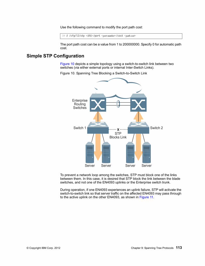
© Copyright IBM Corp. 2012 Chapter 9: Spanning Tree Protocols 113
Use the following command to modify the port path cost:
The port path cost can be a value from 1 to 200000000. Specify 0 for automatic path cost.
Simple STP Configuration
Figure 10 depicts a simple topology using a switch-to-switch link between two switches (via either external ports or internal Inter-Switch Links).
Figure 10. Spanning Tree Blocking a Switch-to-Switch Link
To prevent a network loop among the switches, STP must block one of the links between them. In this case, it is desired that STP block the link between the blade switches, and not one of the EN4093 uplinks or the Enterprise switch trunk.
During operation, if one EN4093 experiences an uplink failure, STP will activate the switch-to-switch link so that server traffic on the affected EN4093 may pass through to the active uplink on the other EN4093, as shown in Figure 11.
>> # /cfg/l2/stp <STG>/port <port number>/cost <path cost>
EnterpriseRoutingSwitches
x
Server Server Server Server
Switch 1 Switch 2
STPBlocks Link
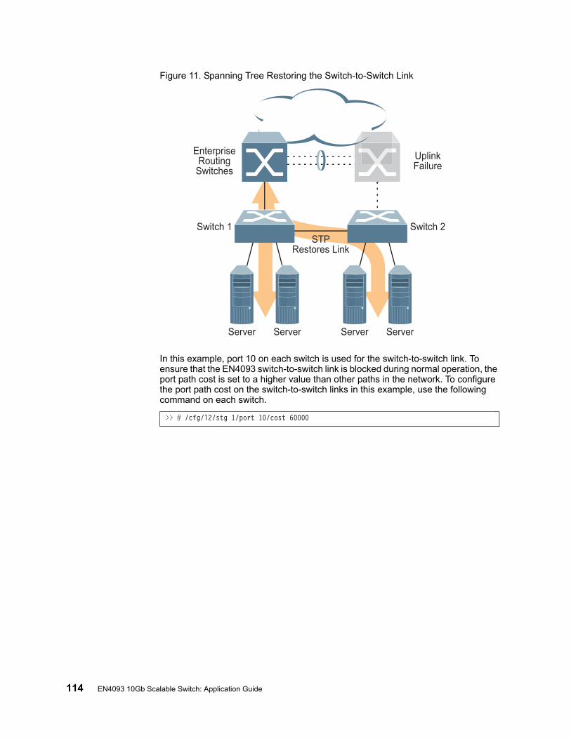
114 EN4093 10Gb Scalable Switch: Application Guide
Figure 11. Spanning Tree Restoring the Switch-to-Switch Link
In this example, port 10 on each switch is used for the switch-to-switch link. To ensure that the EN4093 switch-to-switch link is blocked during normal operation, the port path cost is set to a higher value than other paths in the network. To configure the port path cost on the switch-to-switch links in this example, use the following command on each switch.
>> # /cfg/l2/stg 1/port 10/cost 60000
EnterpriseRoutingSwitches
Server Server Server Server
Switch 1 Switch 2STP
Restores Link
UplinkFailure
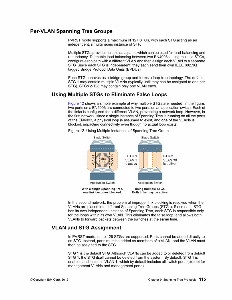
© Copyright IBM Corp. 2012 Chapter 9: Spanning Tree Protocols 115
Per-VLAN Spanning Tree Groups
PVRST mode supports a maximum of 127 STGs, with each STG acting as an independent, simultaneous instance of STP.
Multiple STGs provide multiple data paths which can be used for load-balancing and redundancy. To enable load balancing between two EN4093s using multiple STGs, configure each path with a different VLAN and then assign each VLAN to a separate STG. Since each STG is independent, they each send their own IEEE 802.1Q tagged Bridge Protocol Data Units (BPDUs).
Each STG behaves as a bridge group and forms a loop-free topology. The default STG 1 may contain multiple VLANs (typically until they can be assigned to another STG). STGs 2-128 may contain only one VLAN each.
Using Multiple STGs to Eliminate False Loops
Figure 12 shows a simple example of why multiple STGs are needed. In the figure, two ports on a EN4093 are connected to two ports on an application switch. Each of the links is configured for a different VLAN, preventing a network loop. However, in the first network, since a single instance of Spanning Tree is running on all the ports of the EN4093, a physical loop is assumed to exist, and one of the VLANs is blocked, impacting connectivity even though no actual loop exists.
Figure 12. Using Multiple Instances of Spanning Tree Group
In the second network, the problem of improper link blocking is resolved when the VLANs are placed into different Spanning Tree Groups (STGs). Since each STG has its own independent instance of Spanning Tree, each STG is responsible only for the loops within its own VLAN. This eliminates the false loop, and allows both VLANs to forward packets between the switches at the same time.
VLAN and STG Assignment
In PVRST mode, up to 128 STGs are supported. Ports cannot be added directly to an STG. Instead, ports must be added as members of a VLAN, and the VLAN must then be assigned to the STG.
STG 1 is the default STG. Although VLANs can be added to or deleted from default STG 1, the STG itself cannot be deleted from the system. By default, STG 1 is enabled and includes VLAN 1, which by default includes all switch ports (except for management VLANs and management ports).
VL
AN
1
VL
AN
30
Application Switch
Blade Switch
FalseLoop
Application Switch
Blade Switch
VLAN 1is active
STG 1VLAN 30is active
STG 2x
With a single Spanning Tree,one link becomes blocked.
Using multiple STGs,Both links may be active.
116 EN4093 10Gb Scalable Switch: Application Guide
STG 128 is reserved for switch management. By default, STG 128 is disabled, but includes management VLAN 4095 and the management ports.
By default, all other STGs (STG 2 through 127) are enabled, though they initially include no member VLANs. VLANs must be assigned to STGs. By default, this is done automatically using VLAN Automatic STG Assignment (VASA), though it can also be done manually (see “Manually Assigning STGs” on page 116).
When VASA is enabled (as by default), each time a new VLAN is configured, the switch will automatically assign that new VLAN to its own STG. Conversely, when a VLAN is deleted, if its STG is not associated with any other VLAN, the STG is returned to the available pool.
The specific STG number to which the VLAN is assigned is based on the VLAN number itself. For low VLAN numbers (1 through 127), the switch will attempt to assign the VLAN to its matching STG number. For higher numbered VLANs, the STG assignment is based on a simple modulus calculation; the attempted STG number will “wrap around,” starting back at the top of STG list each time the end of the list is reached. However, if the attempted STG is already in use, the switch will select the next available STG. If an empty STG is not available when creating a new VLAN, the VLAN is automatically assigned to default STG 1.
If ports are tagged, each tagged port sends out a special BPDU containing the tagged information. Also, when a tagged port belongs to more than one STG, the egress BPDUs are tagged to distinguish the BPDUs of one STG from those of another STG.
VASA is enabled by default, but can be disabled or re-enabled using the following command:
If VASA is disabled, when you create a new VLAN, that VLAN automatically belongs to default STG 1. To place the VLAN in a different STG, assign it manually.
VASA applies only to PVRST mode and is ignored in RSTP and MSTP modes.
Manually Assigning STGsThe administrator may manually assign VLANs to specific STGs, whether or not VASA is enabled.
1. If no VLANs exist (other than default VLAN 1), see “Guidelines for Creating VLANs” on page 117 for information about creating VLANs and assigning ports to them.
2. Assign the VLAN to an STG using one of the following methods:
– From within the STG Configuration menu:
– Or from within the VLAN Configuration menu:
When a VLAN is assigned to a new STG, the VLAN is automatically removed from its prior STG.
Note: For proper operation with switches that use Cisco PVST+, it is recommended that you create a separate STG for each VLAN.
>> # /cfg/l2/vlanstg e|d
>> # /cfg/l2/stg <STG number>/add <VLAN number>
>> # /cfg/l2/vlan <VLAN number>/stg <STG number>

© Copyright IBM Corp. 2012 Chapter 9: Spanning Tree Protocols 117
Guidelines for Creating VLANs• When you create a new VLAN, if VASA is enabled (the default), that VLAN is
automatically assigned its own STG. If VASA is disabled, the VLAN automatically belongs to STG 1, the default STG. To place the VLAN in a different STG, see “Manually Assigning STGs” on page 116. The VLAN is automatically removed from its old STG before being placed into the new STG.
• Each VLANs must be contained within a single STG; a VLAN cannot span multiple STGs. By confining VLANs within a single STG, you avoid problems with Spanning Tree blocking ports and causing a loss of connectivity within the VLAN. When a VLAN spans multiple switches, it is recommended that the VLAN remain within the same STG (be assigned the same STG ID) across all the switches.
• If ports are tagged, all trunked ports can belong to multiple STGs.
• A port cannot be directly added to an STG. The port must first be added to a VLAN, and that VLAN added to the desired STG.
Rules for VLAN Tagged Ports• Tagged ports can belong to more than one STG, but untagged ports can belong
to only one STG.
• When a tagged port belongs to more than one STG, the egress BPDUs are tagged to distinguish the BPDUs of one STG from those of another STG.
Adding and Removing Ports from STGs• When you add a port to a VLAN that belongs to an STG, the port is also added to
that STG. However, if the port you are adding is an untagged port and is already a member of another STG, that port will be removed from its current STG and added to the new STG. An untagged port cannot belong to more that one STG.
For example: Assume that VLAN 1 belongs to STG 1, and that port 1 is untagged and does not belong to any STG. When you add port 1 to VLAN 1, port 1 will automatically become part of STG 1.
However, if port 5 is untagged and is a member of VLAN 3 in STG 2, then adding port 5 to VLAN 1 in STG 1 will not automatically add the port to STG 1. Instead, the switch will prompt you to decide whether to change the PVID from 3 to 1:
• When you remove a port from VLAN that belongs to an STG, that port will also be removed from the STG. However, if that port belongs to another VLAN in the same STG, the port remains in the STG.
As an example, assume that port 2 belongs to only VLAN 2, and that VLAN 2 belongs to STG 2. When you remove port 2 from VLAN 2, the port is moved to default VLAN 1 and is removed from STG 2.
However, if port 2 belongs to both VLAN 1 and VLAN 2, and both VLANs belong to STG 2, removing port 2 from VLAN 2 does not remove port 2 from STG 1, because the port is still a member of VLAN 1, which is still a member of STG 1.
• An STG cannot be deleted, only disabled. If you disable the STG while it still contains VLAN members, Spanning Tree will be off on all ports belonging to that VLAN.
The relationship between port, trunk groups, VLANs, and Spanning Trees is shown in Table 14 on page 110.
"Port 5 is an UNTAGGED port and its current PVID is 3.Confirm changing PVID from 3 to 1 [y/n]:" y
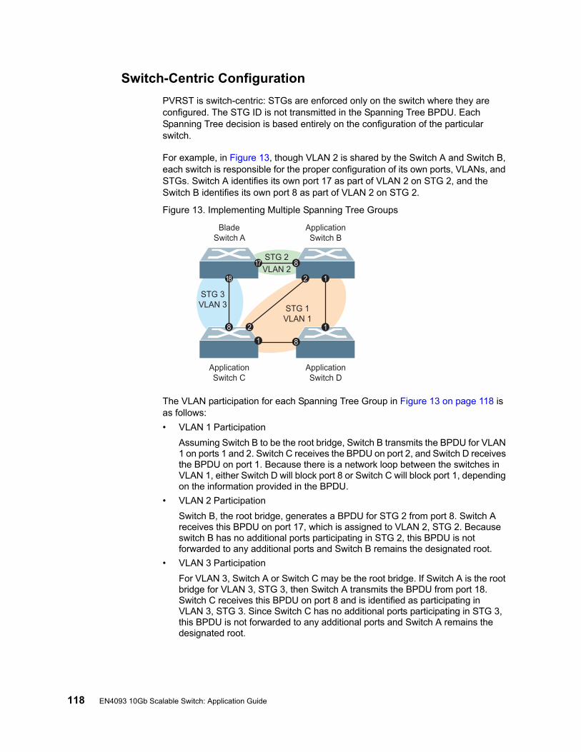
118 EN4093 10Gb Scalable Switch: Application Guide
Switch-Centric Configuration
PVRST is switch-centric: STGs are enforced only on the switch where they are configured. The STG ID is not transmitted in the Spanning Tree BPDU. Each Spanning Tree decision is based entirely on the configuration of the particular switch.
For example, in Figure 13, though VLAN 2 is shared by the Switch A and Switch B, each switch is responsible for the proper configuration of its own ports, VLANs, and STGs. Switch A identifies its own port 17 as part of VLAN 2 on STG 2, and the Switch B identifies its own port 8 as part of VLAN 2 on STG 2.
Figure 13. Implementing Multiple Spanning Tree Groups
The VLAN participation for each Spanning Tree Group in Figure 13 on page 118 is as follows:
• VLAN 1 Participation
Assuming Switch B to be the root bridge, Switch B transmits the BPDU for VLAN 1 on ports 1 and 2. Switch C receives the BPDU on port 2, and Switch D receives the BPDU on port 1. Because there is a network loop between the switches in VLAN 1, either Switch D will block port 8 or Switch C will block port 1, depending on the information provided in the BPDU.
• VLAN 2 Participation
Switch B, the root bridge, generates a BPDU for STG 2 from port 8. Switch A receives this BPDU on port 17, which is assigned to VLAN 2, STG 2. Because switch B has no additional ports participating in STG 2, this BPDU is not forwarded to any additional ports and Switch B remains the designated root.
• VLAN 3 Participation
For VLAN 3, Switch A or Switch C may be the root bridge. If Switch A is the root bridge for VLAN 3, STG 3, then Switch A transmits the BPDU from port 18. Switch C receives this BPDU on port 8 and is identified as participating in VLAN 3, STG 3. Since Switch C has no additional ports participating in STG 3, this BPDU is not forwarded to any additional ports and Switch A remains the designated root.
ApplicationSwitch B
BladeSwitch A
ApplicationSwitch D
ApplicationSwitch C
VLAN 2
STG 2
STG 3VLAN 3 STG 1
VLAN 1
1
1
1
2
2
817
18
8
8
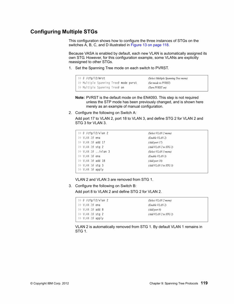
© Copyright IBM Corp. 2012 Chapter 9: Spanning Tree Protocols 119
Configuring Multiple STGs
This configuration shows how to configure the three instances of STGs on the switches A, B, C, and D illustrated in Figure 13 on page 118.
Because VASA is enabled by default, each new VLAN is automatically assigned its own STG. However, for this configuration example, some VLANs are explicitly reassigned to other STGs.
1. Set the Spanning Tree mode on each switch to PVRST.
Note: PVRST is the default mode on the EN4093. This step is not required unless the STP mode has been previously changed, and is shown here merely as an example of manual configuration.
2. Configure the following on Switch A:
Add port 17 to VLAN 2, port 18 to VLAN 3, and define STG 2 for VLAN 2 and STG 3 for VLAN 3.
VLAN 2 and VLAN 3 are removed from STG 1.
3. Configure the following on Switch B:
Add port 8 to VLAN 2 and define STG 2 for VLAN 2.
VLAN 2 is automatically removed from STG 1. By default VLAN 1 remains in STG 1.
>> # /cfg/l2/mrst (Select Multiple Spanning Tree menu)
>> Multiple Spanning Tree# mode pvrst (Set mode to PVRST)
>> Multiple Spanning Tree# on (Turn PVRST on)
>> # /cfg/l2/vlan 2 (Select VLAN 2 menu)
>> VLAN 2# ena (Enable VLAN 2)
>> VLAN 2# add 17 (Add port 17)
>> VLAN 2# stg 2 (Add VLAN 2 to STG 2)
>> VLAN 2# ../vlan 3 (Select VLAN 3 menu)
>> VLAN 3# ena (Enable VLAN 3)
>> VLAN 3# add 18 (Add port 18)
>> VLAN 3# stg 3 (Add VLAN 3 to STG 3)>> VLAN 3# apply
>> # /cfg/l2/vlan 2 (Select VLAN 2 menu)
>> VLAN 2# ena (Enable VLAN 2)
>> VLAN 2# add 8 (Add port 8)
>> VLAN 2# stg 2 (Add VLAN 2 to STG 2)>> VLAN 2# apply

120 EN4093 10Gb Scalable Switch: Application Guide
4. Configure the following on application switch C:
Add port 8 to VLAN 3 and define STG 3 for VLAN 3.
VLAN 3 is automatically removed from STG 1. By default VLAN 1 remains in STG 1.
5. Switch D does not require any special configuration for multiple Spanning Trees. Switch D uses default STG 1 only.
>> # /cfg/l2/vlan 3 (Select VLAN 3 menu)
>> VLAN 3# ena (Enable VLAN 3)
>> VLAN 3# add 8 (Add port 8)
>> VLAN 3# stg 3 (Add VLAN 3 to STG 3)>> VLAN 3# apply
© Copyright IBM Corp. 2012 Chapter 9: Spanning Tree Protocols 121
Rapid Spanning Tree Protocol
RSTP provides rapid convergence of the Spanning Tree and provides the fast re-configuration critical for networks carrying delay-sensitive traffic such as voice and video. RSTP significantly reduces the time to reconfigure the active topology of the network when changes occur to the physical topology or its configuration parameters. RSTP reduces the bridged-LAN topology to a single Spanning Tree.
RSTP was originally defined in IEEE 802.1w (2001) and was later incorporated into IEEE 802.1D (2004), superseding the original STP standard.
RSTP parameters apply only to Spanning Tree Group (STG) 1. The PVRST mode STGs 2-128 are not used when the switch is placed in RSTP mode.
RSTP is compatible with devices that run IEEE 802.1D (1998) Spanning Tree Protocol. If the switch detects IEEE 802.1D (1998) BPDUs, it responds with IEEE 802.1D (1998)-compatible data units. RSTP is not compatible with Per-VLAN Rapid Spanning Tree (PVRST) protocol.
Note: In RSTP mode, Spanning Tree for the management ports is turned off by default.
Port States
RSTP port state controls are the same as for PVRST: discarding, learning, and forwarding.
Due to the sequence involved in these STP states, considerable delays may occur while paths are being resolved. To mitigate delays, ports defined as edge ports (“Port Type and Link Type” on page 127) may bypass the discarding and learning states, and enter directly into the forwarding state.
RSTP Configuration Guidelines
This section provides important information about configuring RSTP. When RSTP is turned on, the following occurs:
• STP parameters apply only to STG 1.
• Only STG 1 is available. All other STGs are turned off.
• All VLANs, including management VLANs, are moved to STG 1.
RSTP Configuration Example
This section provides steps to configure RSTP.
1. Configure port and VLAN membership on the switch.
2. Set the Spanning Tree mode to Rapid Spanning Tree.
>> # /cfg/l2/mrst (Select Multiple Spanning Tree menu)
>> Multiple Spanning Tree# mode rstp (Set mode to Rapid Spanning Tree)
>> Multiple Spanning Tree# on (Turn Rapid Spanning Tree on)

122 EN4093 10Gb Scalable Switch: Application Guide
3. Configure STP Group 1 parameters.
4. Apply and save the configuration.
>> # /cfg/l2/stg 1 (Select Spanning Tree Protocol menu)
>> Spanning Tree Group 1# add 2 (Add VLAN 2 STP Group 1)
© Copyright IBM Corp. 2012 Chapter 9: Spanning Tree Protocols 123
Multiple Spanning Tree Protocol
Note: MSTP is supported in stand-alone (non-stacking) mode only.
Multiple Spanning Tree Protocol (MSTP) extends Rapid Spanning Tree Protocol (RSTP), allowing multiple Spanning Tree Groups (STGs) which may each include multiple VLANs. MSTP was originally defined in IEEE 802.1s (2002) and was later included in IEEE 802.1Q (2003).
In MSTP mode, the EN4093 supports up to 32 instances of Spanning Tree, corresponding to STGs 1-32, with each STG acting as an independent, simultaneous instance of STP.
MSTP allows frames assigned to different VLANs to follow separate paths, with each path based on an independent Spanning Tree instance. This approach provides multiple forwarding paths for data traffic, thereby enabling load-balancing, and reducing the number of Spanning Tree instances required to support a large number of VLANs.
Due to Spanning Tree’s sequence of discarding, learning, and forwarding, lengthy delays may occur while paths are being resolved. Ports defined as edge ports (“Port Type and Link Type” on page 127) bypass the Discarding and Learning states, and enter directly into the Forwarding state.
Note: In MSTP mode, Spanning Tree for the management ports is turned off by default.
MSTP Region
A group of interconnected bridges that share the same attributes is called an MST region. Each bridge within the region must share the following attributes:
• Alphanumeric name
• Revision number
• VLAN-to STG mapping scheme
MSTP provides rapid re-configuration, scalability and control due to the support of regions, and multiple Spanning-Tree instances support within each region.
Common Internal Spanning Tree
The Common Internal Spanning Tree (CIST) provides a common form of Spanning Tree Protocol, with one Spanning-Tree instance that can be used throughout the MSTP region. CIST allows the switch to interoperate with legacy equipment, including devices that run IEEE 802.1D (1998) STP.
CIST allows the MSTP region to act as a virtual bridge to other bridges outside of the region, and provides a single Spanning-Tree instance to interact with them.
CIST port configuration includes Hello time, Edge port enable/disable, and Link Type. These parameters do not affect Spanning Tree Groups 1–128. They apply only when the CIST is used.
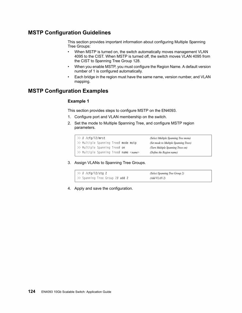
124 EN4093 10Gb Scalable Switch: Application Guide
MSTP Configuration Guidelines
This section provides important information about configuring Multiple Spanning Tree Groups:
• When MSTP is turned on, the switch automatically moves management VLAN 4095 to the CIST. When MSTP is turned off, the switch moves VLAN 4095 from the CIST to Spanning Tree Group 128.
• When you enable MSTP, you must configure the Region Name. A default version number of 1 is configured automatically.
• Each bridge in the region must have the same name, version number, and VLAN mapping.
MSTP Configuration Examples
Example 1
This section provides steps to configure MSTP on the EN4093.
1. Configure port and VLAN membership on the switch.
2. Set the mode to Multiple Spanning Tree, and configure MSTP region parameters.
3. Assign VLANs to Spanning Tree Groups.
4. Apply and save the configuration.
>> # /cfg/l2/mrst (Select Multiple Spanning Tree menu)
>> Multiple Spanning Tree# mode mstp (Set mode to Multiple Spanning Trees)
>> Multiple Spanning Tree# on (Turn Multiple Spanning Trees on)
>> Multiple Spanning Tree# name <name> (Define the Region name)
>> # /cfg/l2/stg 2 (Select Spanning Tree Group 2)
>> Spanning Tree Group 2# add 2 (Add VLAN 2)

© Copyright IBM Corp. 2012 Chapter 9: Spanning Tree Protocols 125
MSTP Configuration Example 2
This configuration shows how to configure MSTP Groups on the switch, as shown in Figure 14.
Figure 14. Implementing Multiple Spanning Tree Groups
This example shows how multiple Spanning Trees can provide redundancy without wasting any uplink ports. In this example, the server ports are split between two separate VLANs. Both VLANs belong to two different MSTP groups. The Spanning Tree priority values are configured so that each routing switch is the root for a different MSTP instance. All of the uplinks are active, with each uplink port backing up the other.
1. Configure port membership and define the STGs for VLAN 1. Enable tagging on uplink ports that share VLANs. Port 19 and port 20 connect to the Enterprise Routing switches.
2. Add server ports 1 and 2 to VLAN 1. Add uplink ports 19 and port 20 to VLAN 1.
>> # /cfg/port 19>> Port 19# tag enable>> Port 19# ../port 20>> Port 20# tag enable
>> Port 20# /cfg/l2/vlan 1 (Select VLAN 1)
>> VLAN 1# ena (Enable VLAN 1)
>> VLAN 1# add 1,2,19,20 (Add ports to VLAN 1)
>> VLAN 1# stg 1 (Set STG 1 for VLAN 1)
EnterpriseRouting Switch
MSTP Group 1Root
EnterpriseRouting Switch
MSTP Group 2Root
Server 1VLAN 1
Server 2VLAN 1
Server 3VLAN 2
Server 4VLAN 2
Blocking VLAN 1Passing VLAN 2
Passing VLAN 1Blocking VLAN 2
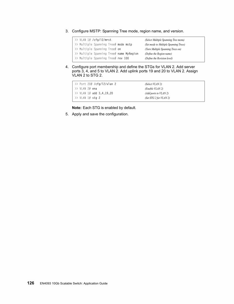
126 EN4093 10Gb Scalable Switch: Application Guide
3. Configure MSTP: Spanning Tree mode, region name, and version.
4. Configure port membership and define the STGs for VLAN 2. Add server ports 3, 4, and 5 to VLAN 2. Add uplink ports 19 and 20 to VLAN 2. Assign VLAN 2 to STG 2.
Note: Each STG is enabled by default.
5. Apply and save the configuration.
>> VLAN 1# /cfg/l2/mrst (Select Multiple Spanning Tree menu)
>> Multiple Spanning Tree# mode mstp (Set mode to Multiple Spanning Trees)
>> Multiple Spanning Tree# on (Turn Multiple Spanning Trees on)
>> Multiple Spanning Tree# name MyRegion (Define the Region name)
>> Multiple Spanning Tree# rev 100 (Define the Revision level)
>> Port 20# /cfg/l2/vlan 2 (Select VLAN 2)
>> VLAN 2# ena (Enable VLAN 2)
>> VLAN 1# add 3,4,19,20 (Add ports to VLAN 2)
>> VLAN 1# stg 2 (Set STG 2 for VLAN 2)
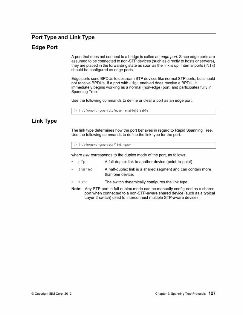
© Copyright IBM Corp. 2012 Chapter 9: Spanning Tree Protocols 127
Port Type and Link Type
Edge Port
A port that does not connect to a bridge is called an edge port. Since edge ports are assumed to be connected to non-STP devices (such as directly to hosts or servers), they are placed in the forwarding state as soon as the link is up. Internal ports (INTx) should be configured as edge ports.
Edge ports send BPDUs to upstream STP devices like normal STP ports, but should not receive BPDUs. If a port with edge enabled does receive a BPDU, it immediately begins working as a normal (non-edge) port, and participates fully in Spanning Tree.
Use the following commands to define or clear a port as an edge port:
Link Type
The link type determines how the port behaves in regard to Rapid Spanning Tree. Use the following commands to define the link type for the port:
where type corresponds to the duplex mode of the port, as follows:
• p2p A full-duplex link to another device (point-to-point)
• shared A half-duplex link is a shared segment and can contain more than one device.
• auto The switch dynamically configures the link type.
Note: Any STP port in full-duplex mode can be manually configured as a shared port when connected to a non-STP-aware shared device (such as a typical Layer 2 switch) used to interconnect multiple STP-aware devices.
>> # /cfg/port <port>/stp/edge {enable|disable}
>> # /cfg/port <port>/stp/link <type>

128 EN4093 10Gb Scalable Switch: Application Guide
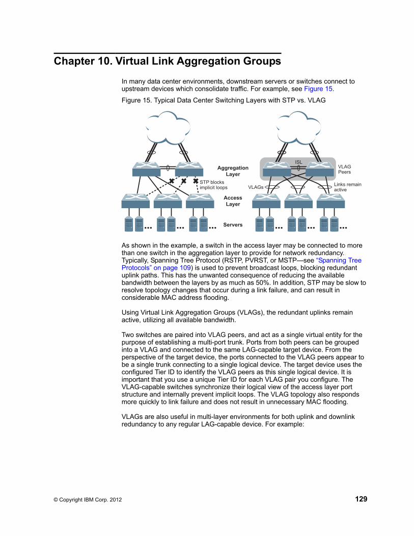
© Copyright IBM Corp. 2012 129
Chapter 10. Virtual Link Aggregation Groups
In many data center environments, downstream servers or switches connect to upstream devices which consolidate traffic. For example, see Figure 15.
Figure 15. Typical Data Center Switching Layers with STP vs. VLAG
As shown in the example, a switch in the access layer may be connected to more than one switch in the aggregation layer to provide for network redundancy. Typically, Spanning Tree Protocol (RSTP, PVRST, or MSTP—see “Spanning Tree Protocols” on page 109) is used to prevent broadcast loops, blocking redundant uplink paths. This has the unwanted consequence of reducing the available bandwidth between the layers by as much as 50%. In addition, STP may be slow to resolve topology changes that occur during a link failure, and can result in considerable MAC address flooding.
Using Virtual Link Aggregation Groups (VLAGs), the redundant uplinks remain active, utilizing all available bandwidth.
Two switches are paired into VLAG peers, and act as a single virtual entity for the purpose of establishing a multi-port trunk. Ports from both peers can be grouped into a VLAG and connected to the same LAG-capable target device. From the perspective of the target device, the ports connected to the VLAG peers appear to be a single trunk connecting to a single logical device. The target device uses the configured Tier ID to identify the VLAG peers as this single logical device. It is important that you use a unique Tier ID for each VLAG pair you configure. The VLAG-capable switches synchronize their logical view of the access layer port structure and internally prevent implicit loops. The VLAG topology also responds more quickly to link failure and does not result in unnecessary MAC flooding.
VLAGs are also useful in multi-layer environments for both uplink and downlink redundancy to any regular LAG-capable device. For example:
STP blocksimplicit loops
Links remainactive
AccessLayer
Servers
AggregationLayer
VLAGPeers
VLAGs
ISL
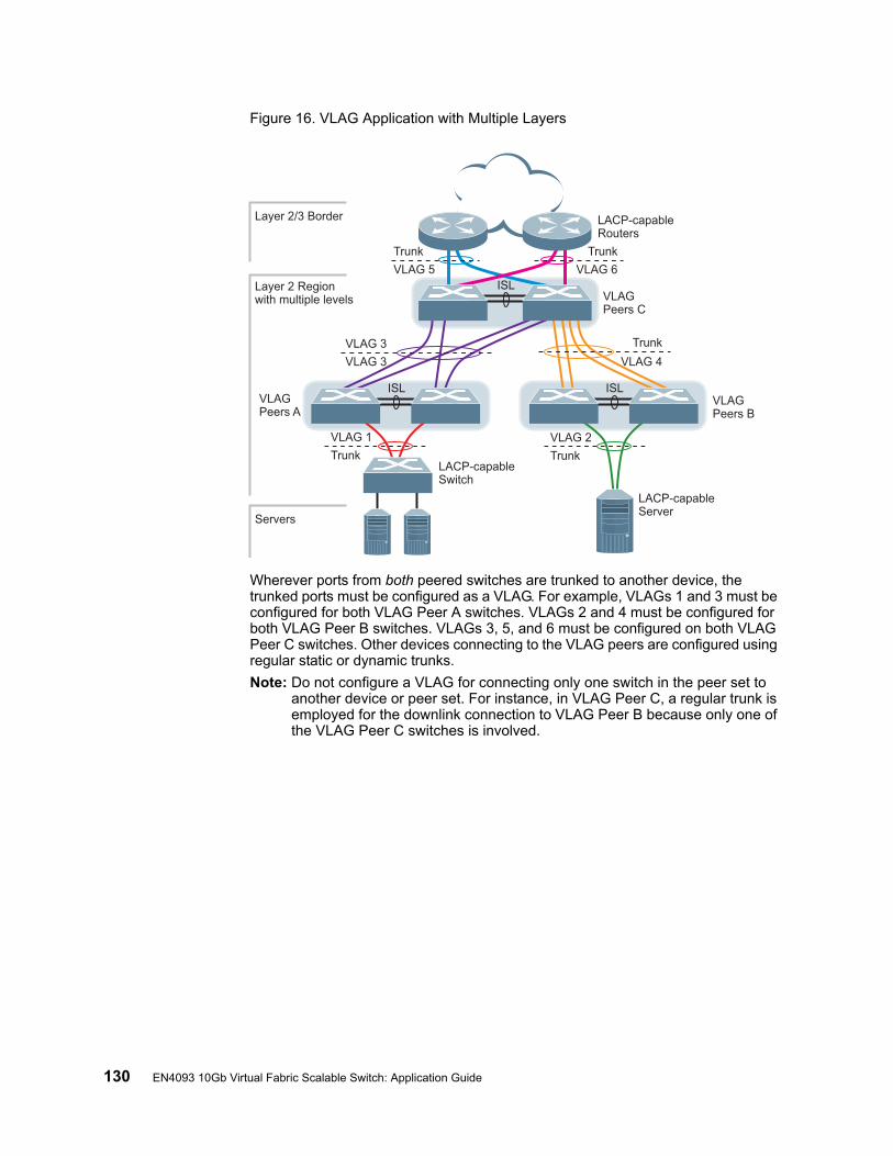
130 EN4093 10Gb Virtual Fabric Scalable Switch: Application Guide
Figure 16. VLAG Application with Multiple Layers
Wherever ports from both peered switches are trunked to another device, the trunked ports must be configured as a VLAG. For example, VLAGs 1 and 3 must be configured for both VLAG Peer A switches. VLAGs 2 and 4 must be configured for both VLAG Peer B switches. VLAGs 3, 5, and 6 must be configured on both VLAG Peer C switches. Other devices connecting to the VLAG peers are configured using regular static or dynamic trunks.
Note: Do not configure a VLAG for connecting only one switch in the peer set to another device or peer set. For instance, in VLAG Peer C, a regular trunk is employed for the downlink connection to VLAG Peer B because only one of the VLAG Peer C switches is involved.
ISL
VLAG 3
VLAG 3
VLAG 5 VLAG 6
TrunkTrunk
VLAG 2
Trunk
ISL
ISL
Layer 2/3 Border
Layer 2 Regionwith multiple levels
Servers
VLAGPeers C
VLAGPeers B
VLAGPeers A
VLAG 1
Trunk
Trunk
VLAG 4
LACP-capableServer
LACP-capableSwitch
LACP-capableRouters
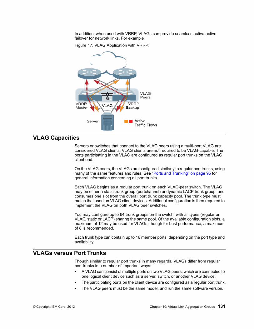
© Copyright IBM Corp. 2012 Chapter 10: Virtual Link Aggregation Groups 131
In addition, when used with VRRP, VLAGs can provide seamless active-active failover for network links. For example
Figure 17. VLAG Application with VRRP:
VLAG CapacitiesServers or switches that connect to the VLAG peers using a multi-port VLAG are considered VLAG clients. VLAG clients are not required to be VLAG-capable. The ports participating in the VLAG are configured as regular port trunks on the VLAG client end.
On the VLAG peers, the VLAGs are configured similarly to regular port trunks, using many of the same features and rules. See “Ports and Trunking” on page 95 for general information concerning all port trunks.
Each VLAG begins as a regular port trunk on each VLAG-peer switch. The VLAG may be either a static trunk group (portchannel) or dynamic LACP trunk group, and consumes one slot from the overall port trunk capacity pool. The trunk type must match that used on VLAG client devices. Additional configuration is then required to implement the VLAG on both VLAG peer switches.
You may configure up to 64 trunk groups on the switch, with all types (regular or VLAG, static or LACP) sharing the same pool. Of the available configuration slots, a maximum of 12 may be used for VLAGs, though for best performance, a maximum of 8 is recommended.
Each trunk type can contain up to 16 member ports, depending on the port type and availability.
VLAGs versus Port TrunksThough similar to regular port trunks in many regards, VLAGs differ from regular port trunks in a number of important ways:
• A VLAG can consist of multiple ports on two VLAG peers, which are connected to one logical client device such as a server, switch, or another VLAG device.
• The participating ports on the client device are configured as a regular port trunk.
• The VLAG peers must be the same model, and run the same software version.
ISL
VLAG
Server
VRRPMaster
VRRPBackup
VLAGPeers
ActiveTraffic Flows
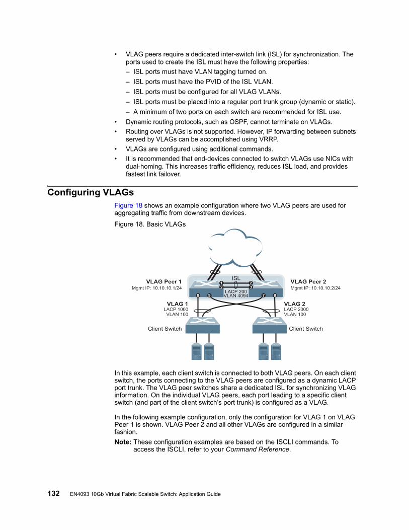
132 EN4093 10Gb Virtual Fabric Scalable Switch: Application Guide
• VLAG peers require a dedicated inter-switch link (ISL) for synchronization. The ports used to create the ISL must have the following properties:
– ISL ports must have VLAN tagging turned on.
– ISL ports must have the PVID of the ISL VLAN.
– ISL ports must be configured for all VLAG VLANs.
– ISL ports must be placed into a regular port trunk group (dynamic or static).
– A minimum of two ports on each switch are recommended for ISL use.
• Dynamic routing protocols, such as OSPF, cannot terminate on VLAGs.
• Routing over VLAGs is not supported. However, IP forwarding between subnets served by VLAGs can be accomplished using VRRP.
• VLAGs are configured using additional commands.
• It is recommended that end-devices connected to switch VLAGs use NICs with dual-homing. This increases traffic efficiency, reduces ISL load, and provides fastest link failover.
Configuring VLAGsFigure 18 shows an example configuration where two VLAG peers are used for aggregating traffic from downstream devices.
Figure 18. Basic VLAGs
In this example, each client switch is connected to both VLAG peers. On each client switch, the ports connecting to the VLAG peers are configured as a dynamic LACP port trunk. The VLAG peer switches share a dedicated ISL for synchronizing VLAG information. On the individual VLAG peers, each port leading to a specific client switch (and part of the client switch’s port trunk) is configured as a VLAG.
In the following example configuration, only the configuration for VLAG 1 on VLAG Peer 1 is shown. VLAG Peer 2 and all other VLAGs are configured in a similar fashion.
Note: These configuration examples are based on the ISCLI commands. To access the ISCLI, refer to your Command Reference.
VLAG Peer 1Mgmt IP: 10.10.10.1/24
VLAG Peer 2Mgmt IP: 10.10.10.2/24
VLAG 1LACP 1000VLAN 100
VLAG 2LACP 2000VLAN 100
ISL
LACP 200VLAN 4094
1
8 9 7 8
223
Client SwitchClient Switch

© Copyright IBM Corp. 2012 Chapter 10: Virtual Link Aggregation Groups 133
Configure the ISL
The ISL connecting the VLAG peers is shared by all their VLAGs. The ISL needs to be configured only once on each VLAG peer.
Note: If STP is desired on the switch, use PVRST or MSTP mode only.
1. Enable VLAG globally.
2. Configure the ISL ports and place them into a port trunk group:
Note: In this case, a dynamic trunk group is shown. A static trunk (portchannel) could be configured instead.
3. Place the ISL into a dedicated VLAN. VLAN 4094 is recommended:
4. Configure VLAG Tier ID. This is used to identify the VLAG switch in a multi-tier environment.
5. If STP is used on the switch, turn STP off for the ISL:
6. Define the VLAG peer relationship:
7. Configure the ISL for the VLAG peer.
Make sure you configure the VLAG peer (VLAG Peer 2) using the same ISL trunk type (dynamic or static), the same VLAN, and the same STP mode and tier ID used on VLAG Peer 1.
# /cfg/l2/vlag enable
# /cfg/port ext1-ext2 # tagEN 4093(config-if)# lacp mode activeEN 4093(config-if)# lacp key 200EN 4093(config-if)# exit
EN 4093(config)# vlan 4094EN 4093(config-vlan)# enableEN 4093(config-vlan)# member 1-2EN 4093(config-vlan)# exit
EN 4093(config)# vlag tier-id 10
EN 4093(config)# spanning-tree stp 20 vlan 4094EN 4093(config)# no spanning-tree stp 20 enable
EN 4093(config)# vlag isl vlan 4094EN 4093(config)# vlag isl adminkey 200
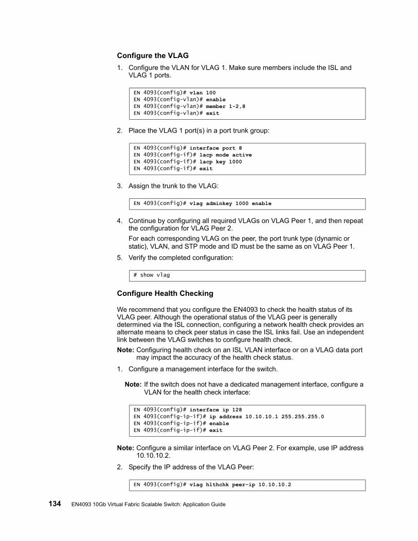
134 EN4093 10Gb Virtual Fabric Scalable Switch: Application Guide
Configure the VLAG
1. Configure the VLAN for VLAG 1. Make sure members include the ISL and VLAG 1 ports.
2. Place the VLAG 1 port(s) in a port trunk group:
3. Assign the trunk to the VLAG:
4. Continue by configuring all required VLAGs on VLAG Peer 1, and then repeat the configuration for VLAG Peer 2.
For each corresponding VLAG on the peer, the port trunk type (dynamic or static), VLAN, and STP mode and ID must be the same as on VLAG Peer 1.
5. Verify the completed configuration:
Configure Health Checking
We recommend that you configure the EN4093 to check the health status of its VLAG peer. Although the operational status of the VLAG peer is generally determined via the ISL connection, configuring a network health check provides an alternate means to check peer status in case the ISL links fail. Use an independent link between the VLAG switches to configure health check.
Note: Configuring health check on an ISL VLAN interface or on a VLAG data port may impact the accuracy of the health check status.
1. Configure a management interface for the switch.
Note: If the switch does not have a dedicated management interface, configure a VLAN for the health check interface:
Note: Configure a similar interface on VLAG Peer 2. For example, use IP address 10.10.10.2.
2. Specify the IP address of the VLAG Peer:
EN 4093(config)# vlan 100EN 4093(config-vlan)# enableEN 4093(config-vlan)# member 1-2,8EN 4093(config-vlan)# exit
EN 4093(config)# interface port 8EN 4093(config-if)# lacp mode activeEN 4093(config-if)# lacp key 1000EN 4093(config-if)# exit
EN 4093(config)# vlag adminkey 1000 enable
# show vlag
EN 4093(config)# interface ip 128EN 4093(config-ip-if)# ip address 10.10.10.1 255.255.255.0EN 4093(config-ip-if)# enableEN 4093(config-ip-if)# exit
EN 4093(config)# vlag hlthchk peer-ip 10.10.10.2
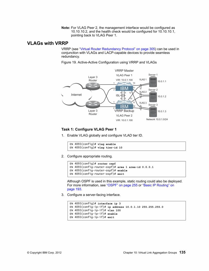
© Copyright IBM Corp. 2012 Chapter 10: Virtual Link Aggregation Groups 135
Note: For VLAG Peer 2, the management interface would be configured as 10.10.10.2, and the health check would be configured for 10.10.10.1, pointing back to VLAG Peer 1.
VLAGs with VRRPVRRP (see “Virtual Router Redundancy Protocol” on page 305) can be used in conjunction with VLAGs and LACP-capable devices to provide seamless redundancy.
Figure 19. Active-Active Configuration using VRRP and VLAGs
Task 1: Configure VLAG Peer 1
1. Enable VLAG globally and configure VLAD tier ID.
2. Configure appropriate routing.
Although OSPF is used in this example, static routing could also be deployed. For more information, see “OSPF” on page 255 or “Basic IP Routing” on page 193.
3. Configure a server-facing interface.
Internet
10.0.1.1
10.0.1.2
10.0.1.3Layer 3
Router
Layer 3
Router1
2
4 5
4 5
1
2
Server 1
Server 2
Server 3
VLAG Peer 1
ISL
VLAG 1
VLAG 2
VLAG 3
VRRP Master
VRRP Backup
Network 10.0.1.0/24
VIR: 10.0.1.100
VLAG Peer 2
VIR: 10.0.1.100
10
11
12
10
11
12
EN 4093(config)# vlag enableEN 4093(config)# vlag tier-id 10
EN 4093(config)# router ospfEN 4093(config-router-ospf)# area 1 area-id 0.0.0.1EN 4093(config-router-ospf)# enableEN 4093(config-router-ospf)# exit
EN 4093(config)# interface ip 3EN 4093(config-ip-if)# ip address 10.0.1.10 255.255.255.0EN 4093(config-ip-if)# vlan 100EN 4093(config-ip-if)# enableEN 4093(config-ip-if)# exit
136 EN4093 10Gb Virtual Fabric Scalable Switch: Application Guide
4. Turn on VRRP and configure the Virtual Interface Router.
5. Set the priority of Virtual Router 1 to 101, so that it becomes the Master.
6. Place the ISL into a dedicated VLAN. VLAN 4094 is recommended:
7. Configure the ISL ports and place them into a port trunk group:
Note: In this case, a dynamic trunk group is shown. A static trunk (portchannel) could be configured instead.
8. If STP is used on the switch, turn STP off for the ISL:
9. Define the VLAG peer relationship:
10. Configure the upstream ports.
EN 4093(config)# router vrrpEN 4093(config-vrrp)# enableEN 4093(config-vrrp)# virtual-router 1 virtual-router-id 1EN 4093(config-vrrp)# virtual-router 1 interface 3EN 4093(config-vrrp)# virtual-router 1 address 10.0.1.100EN 4093(config-vrrp)# virtual-router 1 enable
EN 4093(config-vrrp)# virtual-router 1 priority 101EN 4093(config-vrrp)# exit
EN 4093(config)# vlan 4094EN 4093(config-vlan)# enableEN 4093(config-vlan)# member 4-5EN 4093(config-vlan)# exit
EN 4093(config)# interface port 4-5EN 4093(config-if)# taggingEN 4093(config-if)# pvid 4094EN 4093(config-if)# lacp mode activeEN 4093(config-if)# lacp key 2000EN 4093(config-if)# exit
EN 4093(config)# no spanning-tree stp 20 enableEN 4093(config)# spanning-tree stp 20 vlan 4094
EN 4093(config)# vlag isl vlan 4094EN 4093(config)# vlag isl adminkey 2000
EN 4093(config)# interface port 1EN 4093(config-if)# pvid 10EN 4093(config-if)# exitEN 4093(config)# interface port 2EN 4093(config-if)# pvid 20EN 4093(config-if)# exit
© Copyright IBM Corp. 2012 Chapter 10: Virtual Link Aggregation Groups 137
11. Configure the server ports.
12. Configure all VLANs including VLANs for the VLAGs.
13. Configure Internet-facing interfaces.
14. Place the VLAG port(s) in their port trunk groups.
EN 4093(config)# interface port 10EN 4093(config-if)# pvid 100EN 4093(config-if)# exitEN 4093(config)# interface port 11EN 4093(config-if)# pvid 100EN 4093(config-if)# exitEN 4093(config)# interface port 12EN 4093(config-if)# pvid 100EN 4093(config-if)# exit
EN 4093(config)# vlan 10EN 4093(config-vlan)# enableEN 4093(config-vlan)# member 1EN 4093(config-vlan)# exitEN 4093(config)# vlan 20EN 4093(config-vlan)# enableEN 4093(config-vlan)# member 2EN 4093(config-vlan)# exitEN 4093(config)# vlan 100EN 4093(config-vlan)# enableEN 4093(config-vlan)# member 4-5,10-12EN 4093(config-vlan)# exit
EN 4093(config)# interface ip 1EN 4093(config-ip-if)# ip address 172.1.1.10 255.255.255.0EN 4093(config-ip-if)# vlan 10EN 4093(config-ip-if)# enableEN 4093(config-ip-if)# ip ospf area 1EN 4093(config-ip-if)# ip ospf enableEN 4093(config-ip-if)# exitEN 4093(config)# interface ip 2EN 4093(config-ip-if)# ip address 172.1.3.10 255.255.255.0EN 4093(config-ip-if)# vlan 20EN 4093(config-ip-if)# enableEN 4093(config-ip-if)# ip ospf area 1EN 4093(config-ip-if)# ip ospf enableEN 4093(config-ip-if)# exit
EN 4093(config)# interface port 10EN 4093(config-if)# lacp mode activeEN 4093(config-if)# lacp key 1000EN 4093(config-if)# exitEN 4093(config)# interface port 11EN 4093(config-if)# lacp mode activeEN 4093(config-if)# lacp key 1100EN 4093(config-if)# exitEN 4093(config)# interface port 12EN 4093(config-if)# lacp mode activeEN 4093(config-if)# lacp key 1200EN 4093(config-if)# exit
138 EN4093 10Gb Virtual Fabric Scalable Switch: Application Guide
15. Assign the trunks to the VLAGs:
16. Verify the completed configuration:
Task 2: Configure VLAG Peer 2
The VLAG peer (VLAG Peer 2) must be configured using the same ISL trunk type (dynamic or static), the same VLAN, and the same STP mode and Tier ID used on VLAG Switch 1.
For each corresponding VLAG on the peer, the port trunk type (dynamic or static), VLAN, and STP mode and ID must be the same as on VLAG Switch 1.
1. Enable VLAG globally and configure VLAD tier ID.
2. Configure appropriate routing.
Although OSPF is used in this example, static routing could also be deployed.
3. Configure a server-facing interface.
4. Turn on VRRP and configure the Virtual Interface Router.
5. Place the ISL into a dedicated VLAN. VLAN 4094 is recommended:
EN 4093(config)# vlag adminkey 1000 enableEN 4093(config)# vlag adminkey 1100 enableEN 4093(config)# vlag adminkey 1200 enable
# show vlag
EN 4093(config)# vlag enableEN 4093(config)# vlag tier-id 10
EN 4093(config)# router ospfEN 4093(config-router-ospf)# area 1 area-id 0.0.0.1EN 4093(config-router-ospf)# enableEN 4093(config-router-ospf)# exit
EN 4093(config)# interface ip 3EN 4093(config-ip-if)# ip address 10.0.1.11 255.255.255.0EN 4093(config-ip-if)# vlan 100EN 4093(config-ip-if)# enableEN 4093(config-ip-if)# exit
EN 4093(config)# router vrrpEN 4093(config-vrrp)# enableEN 4093(config-vrrp)# virtual-router 1 virtual-router-id 1EN 4093(config-vrrp)# virtual-router 1 interface 3EN 4093(config-vrrp)# virtual-router 1 address 10.0.1.100EN 4093(config-vrrp)# virtual-router 1 enable
EN 4093(config)# vlan 4094EN 4093(config-vlan)# enableEN 4093(config-vlan)# member 4-5EN 4093(config-vlan)# exit
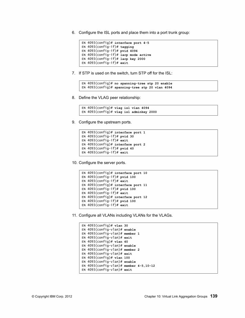
© Copyright IBM Corp. 2012 Chapter 10: Virtual Link Aggregation Groups 139
6. Configure the ISL ports and place them into a port trunk group:
7. If STP is used on the switch, turn STP off for the ISL:
8. Define the VLAG peer relationship:
9. Configure the upstream ports.
10. Configure the server ports.
11. Configure all VLANs including VLANs for the VLAGs.
EN 4093(config)# interface port 4-5EN 4093(config-if)# taggingEN 4093(config-if)# pvid 4094EN 4093(config-if)# lacp mode activeEN 4093(config-if)# lacp key 2000EN 4093(config-if)# exit
EN 4093(config)# no spanning-tree stp 20 enableEN 4093(config)# spanning-tree stp 20 vlan 4094
EN 4093(config)# vlag isl vlan 4094EN 4093(config)# vlag isl adminkey 2000
EN 4093(config)# interface port 1EN 4093(config-if)# pvid 30EN 4093(config-if)# exitEN 4093(config)# interface port 2EN 4093(config-if)# pvid 40EN 4093(config-if)# exit
EN 4093(config)# interface port 10EN 4093(config-if)# pvid 100EN 4093(config-if)# exitEN 4093(config)# interface port 11EN 4093(config-if)# pvid 100EN 4093(config-if)# exitEN 4093(config)# interface port 12EN 4093(config-if)# pvid 100EN 4093(config-if)# exit
EN 4093(config)# vlan 30EN 4093(config-vlan)# enableEN 4093(config-vlan)# member 1EN 4093(config-vlan)# exitEN 4093(config)# vlan 40EN 4093(config-vlan)# enableEN 4093(config-vlan)# member 2EN 4093(config-vlan)# exitEN 4093(config)# vlan 100EN 4093(config-vlan)# enableEN 4093(config-vlan)# member 4-5,10-12EN 4093(config-vlan)# exit
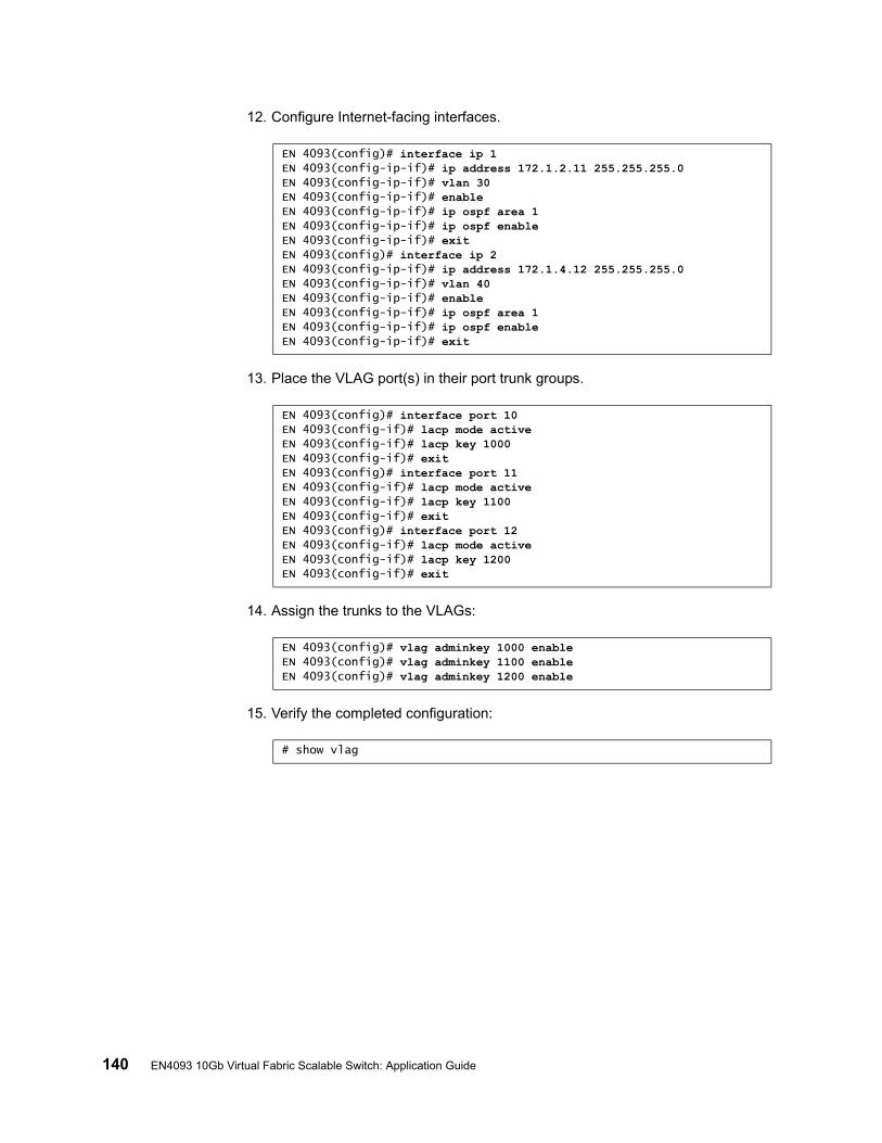
140 EN4093 10Gb Virtual Fabric Scalable Switch: Application Guide
12. Configure Internet-facing interfaces.
13. Place the VLAG port(s) in their port trunk groups.
14. Assign the trunks to the VLAGs:
15. Verify the completed configuration:
EN 4093(config)# interface ip 1EN 4093(config-ip-if)# ip address 172.1.2.11 255.255.255.0EN 4093(config-ip-if)# vlan 30EN 4093(config-ip-if)# enableEN 4093(config-ip-if)# ip ospf area 1EN 4093(config-ip-if)# ip ospf enableEN 4093(config-ip-if)# exitEN 4093(config)# interface ip 2EN 4093(config-ip-if)# ip address 172.1.4.12 255.255.255.0EN 4093(config-ip-if)# vlan 40EN 4093(config-ip-if)# enableEN 4093(config-ip-if)# ip ospf area 1EN 4093(config-ip-if)# ip ospf enableEN 4093(config-ip-if)# exit
EN 4093(config)# interface port 10EN 4093(config-if)# lacp mode activeEN 4093(config-if)# lacp key 1000EN 4093(config-if)# exitEN 4093(config)# interface port 11EN 4093(config-if)# lacp mode activeEN 4093(config-if)# lacp key 1100EN 4093(config-if)# exitEN 4093(config)# interface port 12EN 4093(config-if)# lacp mode activeEN 4093(config-if)# lacp key 1200EN 4093(config-if)# exit
EN 4093(config)# vlag adminkey 1000 enableEN 4093(config)# vlag adminkey 1100 enableEN 4093(config)# vlag adminkey 1200 enable
# show vlag
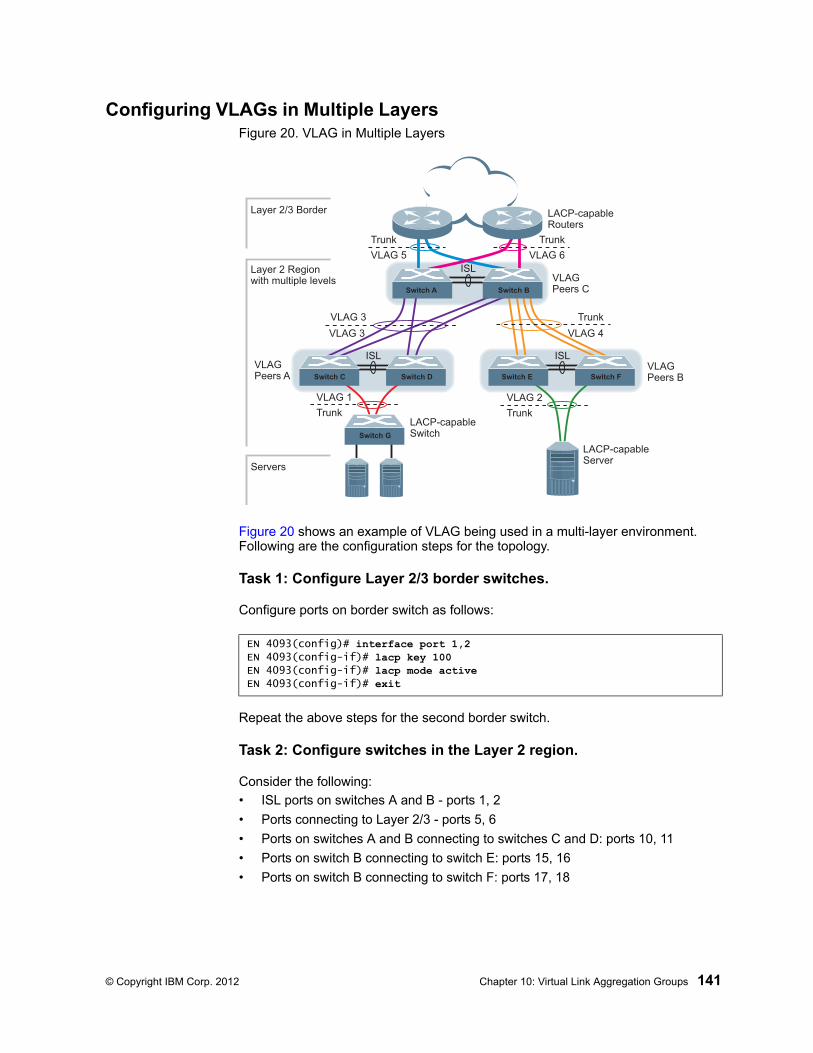
© Copyright IBM Corp. 2012 Chapter 10: Virtual Link Aggregation Groups 141
Configuring VLAGs in Multiple LayersFigure 20. VLAG in Multiple Layers
Figure 20 shows an example of VLAG being used in a multi-layer environment. Following are the configuration steps for the topology.
Task 1: Configure Layer 2/3 border switches.
Configure ports on border switch as follows:
Repeat the above steps for the second border switch.
Task 2: Configure switches in the Layer 2 region.
Consider the following:
• ISL ports on switches A and B - ports 1, 2
• Ports connecting to Layer 2/3 - ports 5, 6
• Ports on switches A and B connecting to switches C and D: ports 10, 11
• Ports on switch B connecting to switch E: ports 15, 16
• Ports on switch B connecting to switch F: ports 17, 18
EN 4093(config)# interface port 1,2EN 4093(config-if)# lacp key 100EN 4093(config-if)# lacp mode activeEN 4093(config-if)# exit
ISL
VLAG 3
VLAG 5 VLAG 6
TrunkTrunk
VLAG 2
Trunk
ISL
ISL
Layer 2/3 Border
Layer 2 Regionwith multiple levels
Servers
VLAGPeers C
VLAGPeers B
VLAGPeers A
VLAG 1
Trunk
Trunk
VLAG 4
LACP-capableServer
LACP-capableSwitch
LACP-capableRouters
Switch A Switch B
Switch C Switch D Switch E Switch F
Switch G
VLAG 3
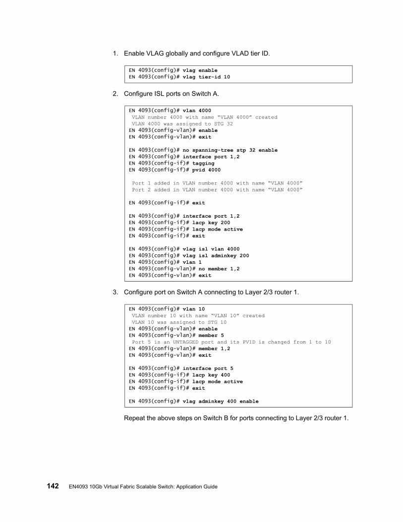
142 EN4093 10Gb Virtual Fabric Scalable Switch: Application Guide
1. Enable VLAG globally and configure VLAD tier ID.
2. Configure ISL ports on Switch A.
3. Configure port on Switch A connecting to Layer 2/3 router 1.
Repeat the above steps on Switch B for ports connecting to Layer 2/3 router 1.
EN 4093(config)# vlag enableEN 4093(config)# vlag tier-id 10
EN 4093(config)# vlan 4000 VLAN number 4000 with name “VLAN 4000” created VLAN 4000 was assigned to STG 32EN 4093(config-vlan)# enableEN 4093(config-vlan)# exit
EN 4093(config)# no spanning-tree stp 32 enableEN 4093(config)# interface port 1,2EN 4093(config-if)# taggingEN 4093(config-if)# pvid 4000
Port 1 added in VLAN number 4000 with name “VLAN 4000” Port 2 added in VLAN number 4000 with name “VLAN 4000”
EN 4093(config-if)# exit
EN 4093(config)# interface port 1,2EN 4093(config-if)# lacp key 200EN 4093(config-if)# lacp mode activeEN 4093(config-if)# exit
EN 4093(config)# vlag isl vlan 4000EN 4093(config)# vlag isl adminkey 200EN 4093(config)# vlan 1EN 4093(config-vlan)# no member 1,2EN 4093(config-vlan)# exit
EN 4093(config)# vlan 10 VLAN number 10 with name “VLAN 10” created VLAN 10 was assigned to STG 10EN 4093(config-vlan)# enableEN 4093(config-vlan)# member 5 Port 5 is an UNTAGGED port and its PVID is changed from 1 to 10EN 4093(config-vlan)# member 1,2EN 4093(config-vlan)# exit
EN 4093(config)# interface port 5EN 4093(config-if)# lacp key 400EN 4093(config-if)# lacp mode activeEN 4093(config-if)# exit
EN 4093(config)# vlag adminkey 400 enable
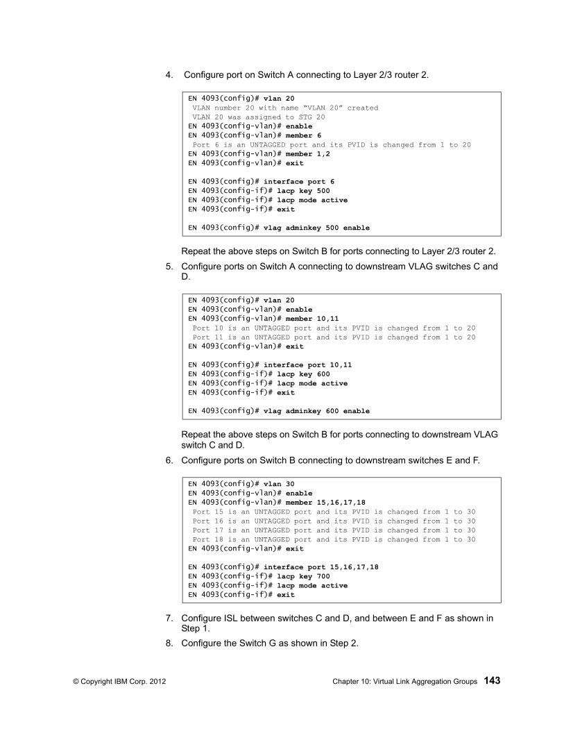
© Copyright IBM Corp. 2012 Chapter 10: Virtual Link Aggregation Groups 143
4. Configure port on Switch A connecting to Layer 2/3 router 2.
Repeat the above steps on Switch B for ports connecting to Layer 2/3 router 2.
5. Configure ports on Switch A connecting to downstream VLAG switches C and D.
Repeat the above steps on Switch B for ports connecting to downstream VLAG switch C and D.
6. Configure ports on Switch B connecting to downstream switches E and F.
7. Configure ISL between switches C and D, and between E and F as shown in Step 1.
8. Configure the Switch G as shown in Step 2.
EN 4093(config)# vlan 20 VLAN number 20 with name “VLAN 20” created VLAN 20 was assigned to STG 20EN 4093(config-vlan)# enableEN 4093(config-vlan)# member 6 Port 6 is an UNTAGGED port and its PVID is changed from 1 to 20EN 4093(config-vlan)# member 1,2EN 4093(config-vlan)# exit
EN 4093(config)# interface port 6EN 4093(config-if)# lacp key 500EN 4093(config-if)# lacp mode activeEN 4093(config-if)# exit
EN 4093(config)# vlag adminkey 500 enable
EN 4093(config)# vlan 20EN 4093(config-vlan)# enableEN 4093(config-vlan)# member 10,11 Port 10 is an UNTAGGED port and its PVID is changed from 1 to 20 Port 11 is an UNTAGGED port and its PVID is changed from 1 to 20EN 4093(config-vlan)# exit
EN 4093(config)# interface port 10,11EN 4093(config-if)# lacp key 600EN 4093(config-if)# lacp mode activeEN 4093(config-if)# exit
EN 4093(config)# vlag adminkey 600 enable
EN 4093(config)# vlan 30EN 4093(config-vlan)# enableEN 4093(config-vlan)# member 15,16,17,18 Port 15 is an UNTAGGED port and its PVID is changed from 1 to 30 Port 16 is an UNTAGGED port and its PVID is changed from 1 to 30 Port 17 is an UNTAGGED port and its PVID is changed from 1 to 30 Port 18 is an UNTAGGED port and its PVID is changed from 1 to 30EN 4093(config-vlan)# exit
EN 4093(config)# interface port 15,16,17,18EN 4093(config-if)# lacp key 700EN 4093(config-if)# lacp mode activeEN 4093(config-if)# exit

144 EN4093 10Gb Virtual Fabric Scalable Switch: Application Guide

© Copyright IBM Corp. 2012 145
Chapter 11. Quality of Service
Quality of Service (QoS) features allow you to allocate network resources to mission-critical applications at the expense of applications that are less sensitive to such factors as time delays or network congestion. You can configure your network to prioritize specific types of traffic, ensuring that each type receives the appropriate QoS level.
The following topics are discussed in this section:
• “QoS Overview” on page 145• “Using ACL Filters” on page 147• “Using DSCP Values to Provide QoS” on page 149• “Using 802.1p Priorities to Provide QoS” on page 153• “Queuing and Scheduling” on page 155
QoS Overview
QoS helps you allocate guaranteed bandwidth to critical applications, and limit bandwidth for less critical applications. Applications such as video and voice must have a certain amount of bandwidth to work correctly; using QoS, you can provide that bandwidth when necessary. Also, you can put a high priority on applications that are sensitive to timing out or those that cannot tolerate delay, assigning that traffic to a high-priority queue.
By assigning QoS levels to traffic flows on your network, you can ensure that network resources are allocated where they are needed most. QoS features allow you to prioritize network traffic, thereby providing better service for selected applications.
Figure 21 on page 145 shows the basic QoS model used by the EN4093 10Gb Scalable Switch (EN4093).
Figure 21. QoS Model
The EN4093 uses the Differentiated Services (DiffServ) architecture to provide QoS functions. DiffServ is described in IETF RFC 2474 and RFC 2475.
With DiffServ, you can establish policies for directing traffic. A policy is a traffic-controlling mechanism that monitors the characteristics of the traffic (for example, its source, destination, and protocol) and performs a controlling action on the traffic when certain characteristics are matched.
Ports
ACLFilter
ACLMeter
Drop/Pass/Re-Mark
ClassifyPackets
PerformActions
EgressIngress
COSQueue
MeterTraffic
Queue andSchedule

146 EN4093 10Gb Scalable Switch: Application Guide
The EN4093 can classify traffic by reading the DiffServ Code Point (DSCP) or IEEE 802.1p priority value, or by using filters to match specific criteria. When network traffic attributes match those specified in a traffic pattern, the policy instructs the EN4093 to perform specified actions on each packet that passes through it. The packets are assigned to different Class of Service (COS) queues and scheduled for transmission.
The basic EN4093 QoS model works as follows:
• Classify traffic:
– Read DSCP
– Read 802.1p Priority
– Match ACL filter parameters
• Meter traffic:
– Define bandwidth and burst parameters
– Select actions to perform on in-profile and out-of-profile traffic
• Perform actions:
– Drop packets
– Pass packets
– Mark DSCP or 802.1p Priority
– Set COS queue (with or without re-marking)
• Queue and schedule traffic:
– Place packets in one of the available COS queues
– Schedule transmission based on the COS queue weight
© Copyright IBM Corp. 2012 Chapter 11: Quality of Service 147
Using ACL Filters
Access Control Lists (ACLs) are filters that allow you to classify and segment traffic, so you can provide different levels of service to different traffic types. Each filter defines conditions that packets must match for inclusion in a particular service class, and also the actions that are performed for matching traffic.
The EN4093 allows you to classify packets based on various parameters. For example:
• Ethernet—source MAC, destination MAC, VLAN number/mask, Ethernet type, priority
• IPv4—source IP address/mask, destination address/mask, type of service, IP protocol number
• IPv6—source IP address/prefix, destination address/prefix, next header, flow label, traffic class
• TCP/UPD—source port, destination port, TCP flag• Packet format—Ethernet format, tagging format, IPv4, IPv6• Egress port
For ACL details, see “Access Control Lists” on page 65.
Summary of ACL Actions
Actions determine how the traffic is treated. The EN4093 QoS actions include the following:
• Pass or Drop the packet• Re-mark the packet with a new DiffServ Code Point (DSCP)• Re-mark the 802.1p field• Set the COS queue
ACL Metering and Re-Marking
You can define a profile for the aggregate traffic flowing through the EN4093 by configuring a QoS meter (if desired) and assigning ACL Groups to ports. When you add ACL Groups to a port, make sure they are ordered correctly in terms of precedence.
Actions taken by an ACL are called In-Profile actions. You can configure additional In-Profile and Out-of-Profile actions on a port. Data traffic can be metered, and re-marked to ensure that the traffic flow provides certain levels of service in terms of bandwidth for different types of network traffic.
148 EN4093 10Gb Scalable Switch: Application Guide
Metering
QoS metering provides different levels of service to data streams through user-configurable parameters. A meter is used to measure the traffic stream against a traffic profile which you create. Thus, creating meters yields In-Profile and Out-of-Profile traffic for each ACL, as follows:
• In-Profile–If there is no meter configured or if the packet conforms to the meter, the packet is classified as In-Profile.
• Out-of-Profile–If a meter is configured and the packet does not conform to the meter (exceeds the committed rate or maximum burst rate of the meter), the packet is classified as Out-of-Profile.
Note: Metering is not supported for IPv6 ACLs. All traffic matching an IPv6 ACL is considered in-profile for re-marking purposes.
Using meters, you set a Committed Rate in Kbps (1000 bits per second in each Kbps). All traffic within this Committed Rate is In-Profile. Additionally, you can set a Maximum Burst Size that specifies an allowed data burst larger than the Committed Rate for a brief period. These parameters define the In-Profile traffic.
Meters keep the sorted packets within certain parameters. You can configure a meter on an ACL, and perform actions on metered traffic, such as packet re-marking.
Re-Marking
Re-marking allows for the treatment of packets to be reset based on new network specifications or desired levels of service. You can configure the ACL to re-mark a packet as follows:
• Change the DSCP value of a packet, used to specify the service level traffic should receive.
• Change the 802.1p priority of a packet.
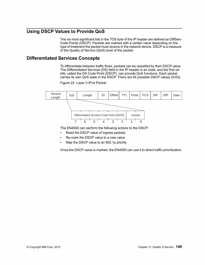
© Copyright IBM Corp. 2012 Chapter 11: Quality of Service 149
Using DSCP Values to Provide QoS
The six most significant bits in the TOS byte of the IP header are defined as DiffServ Code Points (DSCP). Packets are marked with a certain value depending on the type of treatment the packet must receive in the network device. DSCP is a measure of the Quality of Service (QoS) level of the packet.
Differentiated Services Concepts
To differentiate between traffic flows, packets can be classified by their DSCP value. The Differentiated Services (DS) field in the IP header is an octet, and the first six bits, called the DS Code Point (DSCP), can provide QoS functions. Each packet carries its own QoS state in the DSCP. There are 64 possible DSCP values (0-63).
Figure 22. Layer 3 IPv4 Packet
The EN4093 can perform the following actions to the DSCP:
• Read the DSCP value of ingress packets
• Re-mark the DSCP value to a new value
• Map the DSCP value to an 802.1p priority
Once the DSCP value is marked, the EN4093 can use it to direct traffic prioritization.
7 6 5 4 3 2 1 0
Differentiated Services Code Point (DSCP) unused
VersionLength
ToS Length ID Offset TTL Proto FCS DIPSIP Data
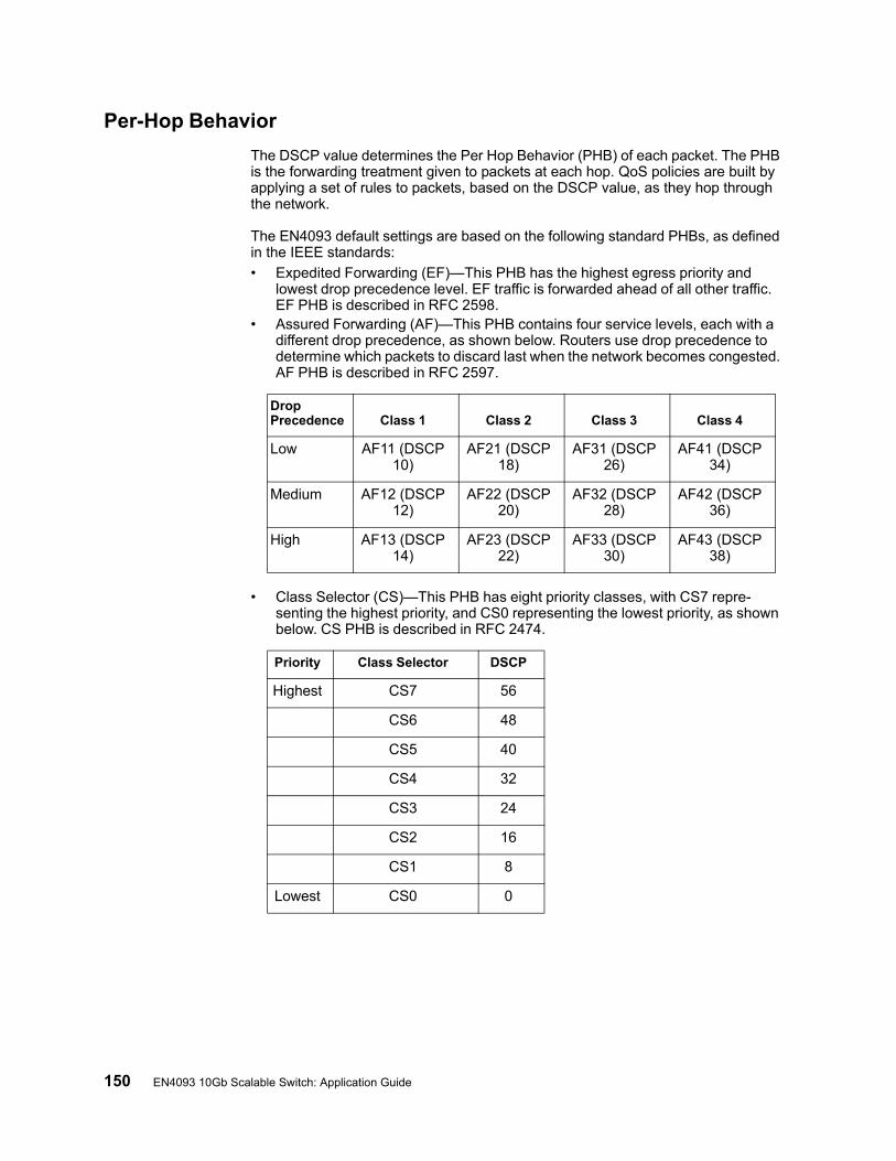
150 EN4093 10Gb Scalable Switch: Application Guide
Per-Hop Behavior
The DSCP value determines the Per Hop Behavior (PHB) of each packet. The PHB is the forwarding treatment given to packets at each hop. QoS policies are built by applying a set of rules to packets, based on the DSCP value, as they hop through the network.
The EN4093 default settings are based on the following standard PHBs, as defined in the IEEE standards:
• Expedited Forwarding (EF)—This PHB has the highest egress priority and lowest drop precedence level. EF traffic is forwarded ahead of all other traffic. EF PHB is described in RFC 2598.
• Assured Forwarding (AF)—This PHB contains four service levels, each with a different drop precedence, as shown below. Routers use drop precedence to determine which packets to discard last when the network becomes congested. AF PHB is described in RFC 2597.
• Class Selector (CS)—This PHB has eight priority classes, with CS7 repre-senting the highest priority, and CS0 representing the lowest priority, as shown below. CS PHB is described in RFC 2474.
DropPrecedence Class 1 Class 2 Class 3 Class 4
Low AF11 (DSCP 10)
AF21 (DSCP 18)
AF31 (DSCP 26)
AF41 (DSCP 34)
Medium AF12 (DSCP 12)
AF22 (DSCP 20)
AF32 (DSCP 28)
AF42 (DSCP 36)
High AF13 (DSCP 14)
AF23 (DSCP 22)
AF33 (DSCP 30)
AF43 (DSCP 38)
Priority Class Selector DSCP
Highest CS7 56
CS6 48
CS5 40
CS4 32
CS3 24
CS2 16
CS1 8
Lowest CS0 0
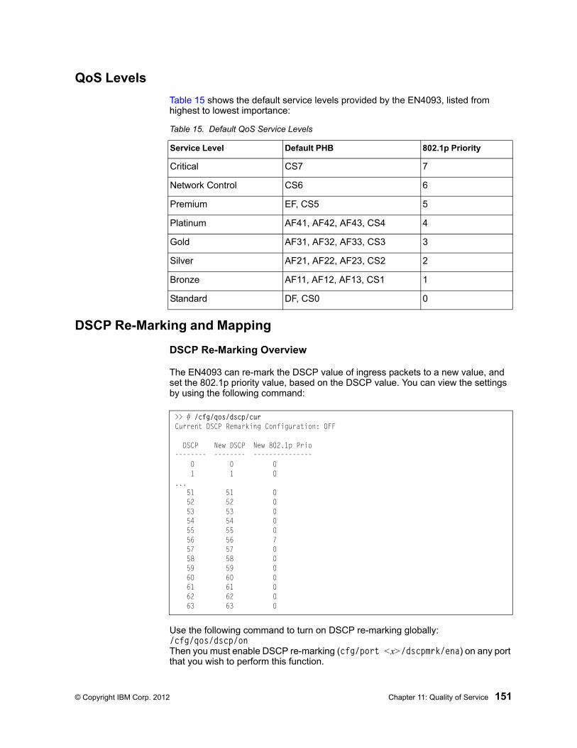
© Copyright IBM Corp. 2012 Chapter 11: Quality of Service 151
QoS Levels
Table 15 shows the default service levels provided by the EN4093, listed from highest to lowest importance:
DSCP Re-Marking and Mapping
DSCP Re-Marking Overview
The EN4093 can re-mark the DSCP value of ingress packets to a new value, and set the 802.1p priority value, based on the DSCP value. You can view the settings by using the following command:
Use the following command to turn on DSCP re-marking globally: /cfg/qos/dscp/on Then you must enable DSCP re-marking (cfg/port <x>/dscpmrk/ena) on any port that you wish to perform this function.
Table 15. Default QoS Service Levels
Service Level Default PHB 802.1p Priority
Critical CS7 7
Network Control CS6 6
Premium EF, CS5 5
Platinum AF41, AF42, AF43, CS4 4
Gold AF31, AF32, AF33, CS3 3
Silver AF21, AF22, AF23, CS2 2
Bronze AF11, AF12, AF13, CS1 1
Standard DF, CS0 0
>> # /cfg/qos/dscp/curCurrent DSCP Remarking Configuration: OFF
DSCP New DSCP New 802.1p Prio-------- -------- --------------- 0 0 0 1 1 0... 51 51 0 52 52 0 53 53 0 54 54 0 55 55 0 56 56 7 57 57 0 58 58 0 59 59 0 60 60 0 61 61 0 62 62 0 63 63 0
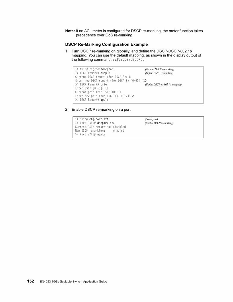
152 EN4093 10Gb Scalable Switch: Application Guide
Note: If an ACL meter is configured for DSCP re-marking, the meter function takes precedence over QoS re-marking.
DSCP Re-Marking Configuration Example
1. Turn DSCP re-marking on globally, and define the DSCP-DSCP-802.1p mapping. You can use the default mapping, as shown in the display output of the following command: /cfg/qos/dscp/cur
2. Enable DSCP re-marking on a port.
>> Main# cfg/qos/dscp/on (Turn on DSCP re-marking)>> DSCP Remark# dscp 8 (Define DSCP re-marking)Current DSCP remark (for DSCP 8): 8Enter new DSCP remark (for DSCP 8) [0-63]: 10>> DSCP Remark# prio (Define DSCP-to-802.1p mapping)Enter DSCP [0-63]: 10Current prio (for DSCP 10): 1Enter new prio (for DSCP 10) [0-7]: 2>> DSCP Remark# apply
>> Main# cfg/port ext1 (Select port)>> Port EXT1# dscpmrk ena (Enable DSCP re-marking)Current DSCP remarking: disabledNew DSCP remarking: enabled>> Port EXT1# apply

© Copyright IBM Corp. 2012 Chapter 11: Quality of Service 153
Using 802.1p Priorities to Provide QoS
802.1p Overview
IBM Networking OS provides Quality of Service functions based on the priority bits in a packet’s VLAN header. (The priority bits are defined by the 802.1p standard within the IEEE 802.1q VLAN header.) The 802.1p bits, if present in the packet, specify the priority that should be given to packets during forwarding. Packets with a numerically higher (non-zero) priority are given forwarding preference over packets with lower priority bit value.
The IEEE 802.1p standard uses eight levels of priority (0-7). Priority 7 is assigned to highest priority network traffic, such as OSPF or RIP routing table updates, priorities 5-6 are assigned to delay-sensitive applications such as voice and video, and lower priorities are assigned to standard applications. A value of 0 (zero) indicates a “best effort” traffic prioritization, and this is the default when traffic priority has not been configured on your network. The EN4093 can filter packets based on the 802.1p values, and it can assign or overwrite the 802.1p value in the packet.
Figure 23. Layer 2 802.1q/802.1p VLAN Tagged Packet
Ingress packets receive a priority value, as follows:
• Tagged packets—EN4093 reads the 802.1p priority in the VLAN tag.
• Untagged packets—EN4093 tags the packet and assigns an 802.1p priority, based on the port’s default priority (/cfg/port <x>/8021ppri).
Egress packets are placed in a COS queue based on the priority value, and scheduled for transmission based on the scheduling weight of the COS queue.
7 6 5 4 3 2 1 0
Priority
7 6 5 4 3 2 1 0
VLAN Identifier (VID)
SFD DMAC SMAC Tag E Type Data FCSPreamble
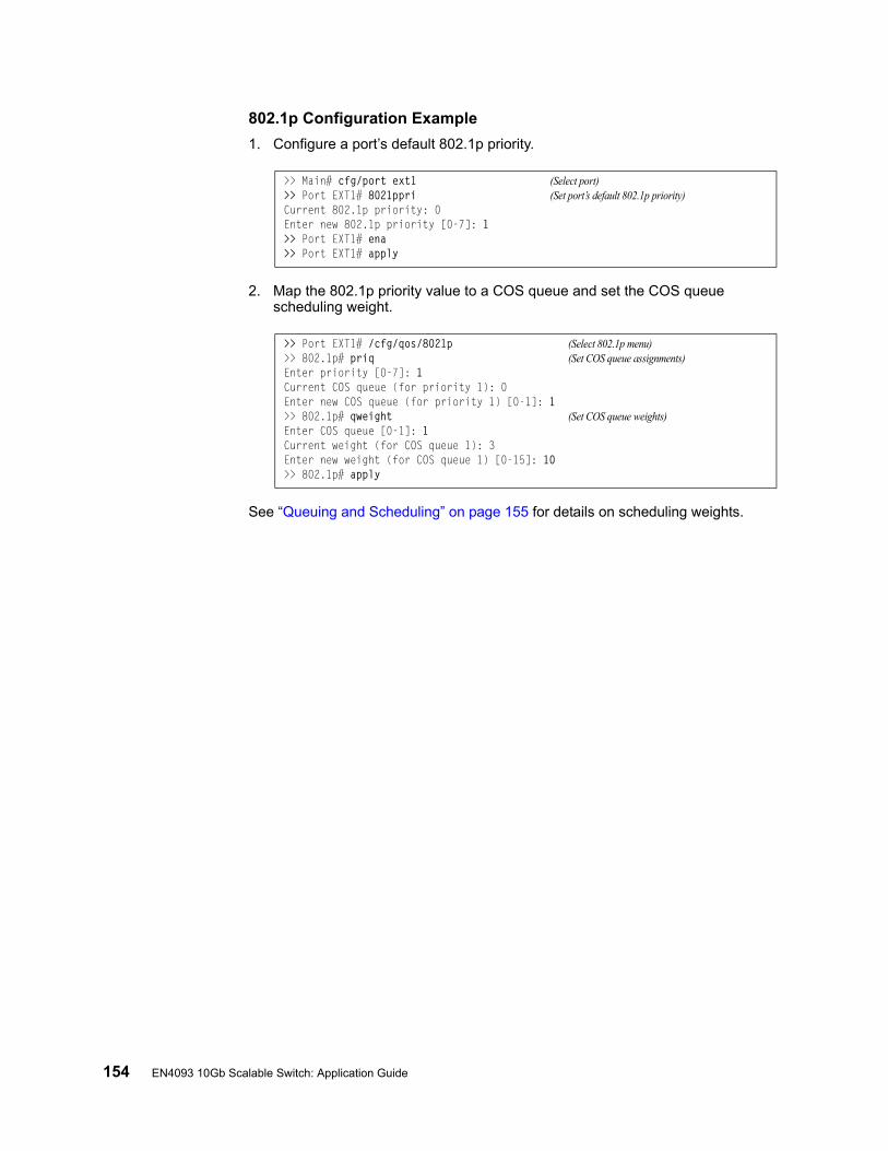
154 EN4093 10Gb Scalable Switch: Application Guide
802.1p Configuration Example
1. Configure a port’s default 802.1p priority.
2. Map the 802.1p priority value to a COS queue and set the COS queue scheduling weight.
See “Queuing and Scheduling” on page 155 for details on scheduling weights.
>> Main# cfg/port ext1 (Select port)>> Port EXT1# 8021ppri (Set port’s default 802.1p priority)Current 802.1p priority: 0Enter new 802.1p priority [0-7]: 1>> Port EXT1# ena>> Port EXT1# apply
>> Port EXT1# /cfg/qos/8021p (Select 802.1p menu)>> 802.1p# priq (Set COS queue assignments)Enter priority [0-7]: 1Current COS queue (for priority 1): 0Enter new COS queue (for priority 1) [0-1]: 1>> 802.1p# qweight (Set COS queue weights)Enter COS queue [0-1]: 1Current weight (for COS queue 1): 3Enter new weight (for COS queue 1) [0-15]: 10>> 802.1p# apply
© Copyright IBM Corp. 2012 Chapter 11: Quality of Service 155
Queuing and Scheduling
The EN4093 can be configured to have either 2 or 8 output Class of Service (COS) queues per port, into which each packet is placed. Each packet’s 802.1p priority determines its COS queue, except when an ACL action sets the COS queue of the packet.
You can configure the following attributes for COS queues:
• Map 802.1p priority value to a COS queue
• Define the scheduling weight of each COS queue
Use the 802.1p menu (/cfg/qos/8021p) to configure COS queues.
The scheduling weight can be set from 0 to 15. Weight values from 1 to 15 set the queue to use weighted round-robin (WRR) scheduling, which distributes larger numbers of packets to queues with the highest weight values. For distribution purposes, each packet is counted the same, regardless of the packet’s size.
A scheduling weight of 0 (zero) indicates strict priority. Traffic in strict priority queue has precedence over other all queues. If more than one queue is assigned a weight of 0, the strict queue with highest queue number will be served first. Once all traffic in strict queues is delivered, any remaining bandwidth will be allocated to the WRR queues, divided according to their weight values.
Note: Use caution when assigning strict scheduling to queues. Heavy traffic in queues assigned with a weight of 0 can starve lower priority queues.
For a scheduling method that uses a weighted deficit round-robin (WDRR) algorithm, distributing packets with an awareness of packet size, see “Enhanced Transmission Selection” on page 245.

156 EN4093 10Gb Scalable Switch: Application Guide

© Copyright IBM Corp. 2012 157
Part 4: Advanced Switch-ing Features

158 EN4093 10Gb Scalable Switch: Application Guide
© Copyright IBM Corp. 2012 159
Chapter 12. Virtualization
Virtualization allows resources to be allocated in a fluid manner based on the logical needs of the data center, rather than on the strict, physical nature of components. The following virtualization features are included in IBM Networking OS 7.2 on the EN4093 10Gb Scalable Switch (EN4093):
• Virtual Local Area Networks (VLANs)
VLANs are commonly used to split groups of networks into manageable broadcast domains, create logical segmentation of workgroups, and to enforce security policies among logical network segments.
For details on this feature, see “VLANs” on page 77.
• Port trunking
A port trunk pools multiple physical switch ports into a single, high-bandwidth logical link to other devices. In addition to aggregating capacity, trunks provides link redundancy.
For details on this feature, see “Ports and Trunking” on page 95.
• Virtual Link Aggregation (VLAGs)
With VLAGs, two switches can act as a single logical device for the purpose of establishing port trunking. Active trunk links from one device can lead to both VLAG peer switches, providing enhanced redundancy, including active-active VRRP configuration.
For details on this feature, see “Virtual Link Aggregation Groups” on page 139
• VMready
The switch’s VMready software makes it virtualization aware. Servers that run hypervisor software with multiple instances of one or more operating systems can present each as an independent virtual machine (VM). With VMready, the switch automatically discovers virtual machines (VMs) connected to switch.
For details on this feature, see “VMready” on page 173.
IBM Networking OS virtualization features provide a highly-flexible framework for allocating and managing switch resources.

160 EN4093 10Gb Scalable Switch: Application Guide

© Copyright IBM Corp. 2012 161
Chapter 13. Virtual NICs
A Network Interface Controller (NIC) is a component within a blade server that allows the server to be connected to a network. The NIC provides the physical point of connection, as well as internal software for encoding and decoding network packets.
Virtualizing the NIC helps to resolve issues caused by limited NIC slot availability. By virtualizing a 10Gbps NIC, its resources can be divided into multiple logical instances known as virtual NICs (vNICs). Each vNIC appears as a regular, independent NIC to the server operating system or a hypervisor, with each vNIC using some portion of the physical NIC’s overall bandwidth.
Figure 24. Virtualizing the NIC for Multiple Virtual Pipes on Each Link
A EN4093 with IBM Networking OS 7.2 supports the Emulex Virtual Fabric Adapter (VFA) for IBM Flex System to provide the following vNIC features:
• Up to four vNICs are supported on each internal switch port.
• Each vNIC can accommodate one of the following traffic types: regular Ethernet, iSCSI, or Fibre Channel over Ethernet (FCoE).
• vNICs with traffic of the same type can be grouped together, along with regular internal ports, external uplink ports, and trunk groups, to define vNIC groups for enforcing communication boundaries.
• In the case of a failure on the external uplink ports associated with a vNIC group, the switch can signal affected vNICs for failover while permitting other vNICs to continue operation.
• Each vNIC can be allocated a symmetric percentage of the 10Gbps bandwidth on the link (from NIC to switch, and from switch to NIC).
• The EN4093 can be used as the single point of vNIC configuration.
The following restriction applies to vNICs:
• vNICs are not supported simultaneously with VM groups (see “VMready” on page 173) on the same switch ports.
NIC
OS or
Hypervisor
Blade Server 1
Blade
Switch 1
Blade
Switch 2
10 Gbps Link withMultiple Virtual Pipes
VNIC
VNIC
VNIC
VNIC
VNIC
VNIC
VNIC
VNIC
PhysicalNIC Ports
InternalSwitch Ports
INT1
INT1
162 EN4093 10Gb Scalable Switch: Application Guide
By default, vNICs are disabled. The administrator can enable vNICs and configure vNIC features on the switch using the standard management options such as the IBM Networking OS CLI, the ISCLI, and the Browser-based Interface (BBI). In the menu-based CLI, vNIC options are configured from the vNIC Configuration Menu:
To enable the vNIC feature on the switch, use the following command on the vNIC Configuration Menu:
Note: The Emulex Virtual Fabric Adapter for IBM Flex System can also operate in Physical NIC (PNIC) mode, in which case vNIC features are non-applicable.
vNIC IDs
vNIC IDs on the Switch
IBM Networking OS 7.2 supports up to four vNICs attached to each internal switch port. Each vNIC is provided its own independent virtual pipe on the port.
On stand-alone (non-stacked) switches, each vNIC is identified by port and vNIC number:
<port number or alias>.<vNIC pipe number (1-4)>
For example:
INTA1.1, INTA1.2, INTA1.3, and INTA1.4 represent the vNICs on port INTA1.
INTA2.1, INTA2.2, INTA2.3, and INTA2.4 represent the vNICs on port INTA2, etc.
These vNIC IDs are used when adding vNICs to vNIC groups, and are shown in some configuration and information displays.
Whenever switches are stacked, the switch csnum ID is also required:
<switch csnum>:<port number or alias>.<vNIC pipe number (1-4)>
For example:
INTA2.3 refers to port ITNA2, vNIC 3.
Note: The configuration examples in this chapter depict stand-alone (non-stacked) port and vNIC designations.
>> Main# /cfg/virt/vnic
>> vNIC Global Configuration# on
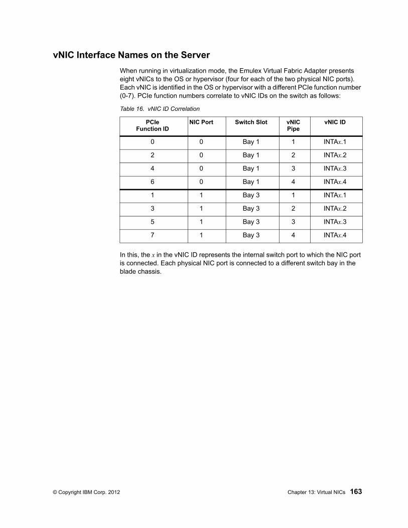
© Copyright IBM Corp. 2012 Chapter 13: Virtual NICs 163
vNIC Interface Names on the Server
When running in virtualization mode, the Emulex Virtual Fabric Adapter presents eight vNICs to the OS or hypervisor (four for each of the two physical NIC ports). Each vNIC is identified in the OS or hypervisor with a different PCIe function number (0-7). PCIe function numbers correlate to vNIC IDs on the switch as follows:
In this, the x in the vNIC ID represents the internal switch port to which the NIC port is connected. Each physical NIC port is connected to a different switch bay in the blade chassis.
Table 16. vNIC ID Correlation
PCIeFunction ID
NIC Port Switch Slot vNIC Pipe
vNIC ID
0 0 Bay 1 1 INTAx.1
2 0 Bay 1 2 INTAx.2
4 0 Bay 1 3 INTAx.3
6 0 Bay 1 4 INTAx.4
1 1 Bay 3 1 INTAx.1
3 1 Bay 3 2 INTAx.2
5 1 Bay 3 3 INTAx.3
7 1 Bay 3 4 INTAx.4
164 EN4093 10Gb Scalable Switch: Application Guide
vNIC Bandwidth Metering
IBM Networking OS 7.2 supports bandwidth metering for vNIC traffic. By default, each of the four vNICs on any given port is allowed an equal share (25%) of NIC capacity when enabled. However, you may configure the percentage of available switch port bandwidth permitted to each vNIC.
vNIC bandwidth can be configured as a value from 1 to 100, with each unit representing 1% (or 100Mbps) of the 10Gbps link. By default, each vNICs enabled on a port is assigned 25 units (equal to 25% of the link, or 2.5Gbps). When traffic from the switch to the vNIC reaches its assigned bandwidth limit, the switch will drop packets egressing to the affected vNIC.
Note: Bandwidth metering drops excess packets when configured limits are reached. Consider using the ETS feature in applications where packet loss is not desirable (see “Enhanced Transmission Selection” on page 245).
To change the bandwidth allocation, use the following commands:
Note: vNICs that are disabled (by default or with command /cfg/virt/vnic/port <x>/vnic <x>/dis) are automatically allocated a bandwidth value of 0.
A combined maximum of 100 units can be allocated among vNIC pipes enabled for any specific port (bandwidth values for disabled pipes are not counted). If more than 100 units are assigned to enabled pipes, an error will be reported when attempting to apply the configuration.
The bandwidth metering configuration is automatically synchronized between the switch and vNICs for regular Ethernet and iSCSI traffic. Once configured on the switch, there is no need to manually configure vNIC bandwidth metering limits on the NIC.
Note: FCoE vNIC does not use egress metering. ETS and PFC must be enabled to ensure lossless transmission for FCoE traffic. ETS does traffic shaping. You can configure a minimum bandwidth for each traffic class. For example, 40% for FCoE priority 3, 60% for the Ethernet traffic. FCoE traffic gets 40% minimum guaranteed bandwidth. If the Ethernet traffic only consumes 30% bandwidth, then FCoE traffic can use 70%. If there is no other Ethernet traffic, then FCoE traffic can use 100%. The FCoE vNIC can use up to 100% of the bandwidth, with a minimum guaranteed bandwidth of 40%.
>> # /cfg/virt/vnic/port <port number or alias> (Select a switch port)>> Port vNICs# vnic <vNIC number (1-4)> (Select a vNIC pipe on the port)>> vNIC# bw <maximum bandwidth units> (Set the permitted vNIC bandwidth)
© Copyright IBM Corp. 2012 Chapter 13: Virtual NICs 165
vNIC Groups
vNICs can be grouped together, along with internal and external switch ports and trunks, into vNIC groups. Each vNIC group is essentially a separate virtual network within the switch. Elements within a vNIC group have a common logical function and can communicate with each other, while elements in different vNIC groups are separated.
IBM Networking OS 7.2 supports up to 32 independent vNIC groups. To enforce group boundaries, each vNIC group is assigned its own unique VLAN.
The VLAN configured for the vNIC group will be automatically assigned to member vNICs, ports, and trunks and should not be manually configured for those elements.
Note: Once a VLAN is assigned to a vNIC group, that VLAN is used only for vNIC purposes and is no longer available for configuration under the regular VLAN menu (/cfg/l2/vlan). Likewise, any VLAN configured for regular purposes (via the /cfg/l2/vlan menu) cannot be configured as a vNIC group VLAN.
The vNIC group rules are as follows:
• vNIC groups may have one or more vNIC members. However, any given vNIC can be a member of only one vNIC group.
• All vNICs on a given port must belong to different vNIC groups.
• Each vNIC group may contain traffic of one type only (either regular Ethernet, iSCSI, or FCoE). Traffic of different types may not be mixed within any vNIC group.
• External ports that are part of a trunk may not be individually added to a vNIC group. Only one individual external port, one static trunk, or one dynamic trunk (consisting of multiple external ports) may be added to any given vNIC group.
• In dedicated mode, for any internal ports, external port, or port trunk group connected to regular (non-vNIC) devices:
– These elements can be placed in only one vNIC group (they cannot be members of multiple vNIC groups).
– Once added to a vNIC group, the PVID for the element is automatically set to use the vNIC group VLAN number, and PVID tagging on the element is automatically disabled.
• By default, STP is disabled on any external port added to a vNIC group. STP can be re-enabled on the port if desired.
• Because regular, inner VLAN IDs are ignored by the switch for traffic in vNIC groups, following rules and restrictions apply:
– The inner VLAN tag may specify any VLAN ID in the full, supported range (1 to 4095) and may even duplicate outer vNIC group VLAN IDs. However, in the shared mode, inner VLAN tag and the vNIC group VLAN ID should be the same.
– Per-VLAN IGMP snooping is not supported in vNIC groups.
– The inner VLAN tag is not processed in any way in vNIC groups: The inner tag cannot be stripped or added on port egress, is not used to restrict multicast traffic, is not matched against ACL filters, and does not influence Layer 3 switching.
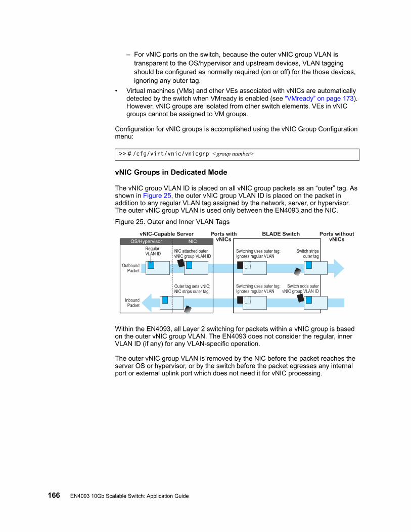
166 EN4093 10Gb Scalable Switch: Application Guide
– For vNIC ports on the switch, because the outer vNIC group VLAN is transparent to the OS/hypervisor and upstream devices, VLAN tagging should be configured as normally required (on or off) for the those devices, ignoring any outer tag.
• Virtual machines (VMs) and other VEs associated with vNICs are automatically detected by the switch when VMready is enabled (see “VMready” on page 173). However, vNIC groups are isolated from other switch elements. VEs in vNIC groups cannot be assigned to VM groups.
Configuration for vNIC groups is accomplished using the vNIC Group Configuration menu:
vNIC Groups in Dedicated Mode
The vNIC group VLAN ID is placed on all vNIC group packets as an “outer” tag. As shown in Figure 25, the outer vNIC group VLAN ID is placed on the packet in addition to any regular VLAN tag assigned by the network, server, or hypervisor. The outer vNIC group VLAN is used only between the EN4093 and the NIC.
Figure 25. Outer and Inner VLAN Tags
Within the EN4093, all Layer 2 switching for packets within a vNIC group is based on the outer vNIC group VLAN. The EN4093 does not consider the regular, inner VLAN ID (if any) for any VLAN-specific operation.
The outer vNIC group VLAN is removed by the NIC before the packet reaches the server OS or hypervisor, or by the switch before the packet egresses any internal port or external uplink port which does not need it for vNIC processing.
>> # /cfg/virt/vnic/vnicgrp <group number>
OutboundPacket
InboundPacket
RegularVLAN ID NIC attached outer
vNIC group VLAN ID
Switch adds outervNIC group VLAN ID
Outer tag sets vNIC;NIC strips outer tag
Switching uses outer tag;Ignores regular VLAN
Switching uses outer tag;Ignores regular VLAN
Switch stripsouter tag
vNIC-Capable Server BLADE Switch Ports withoutvNICs
Ports withvNICsOS/Hypervisor NIC
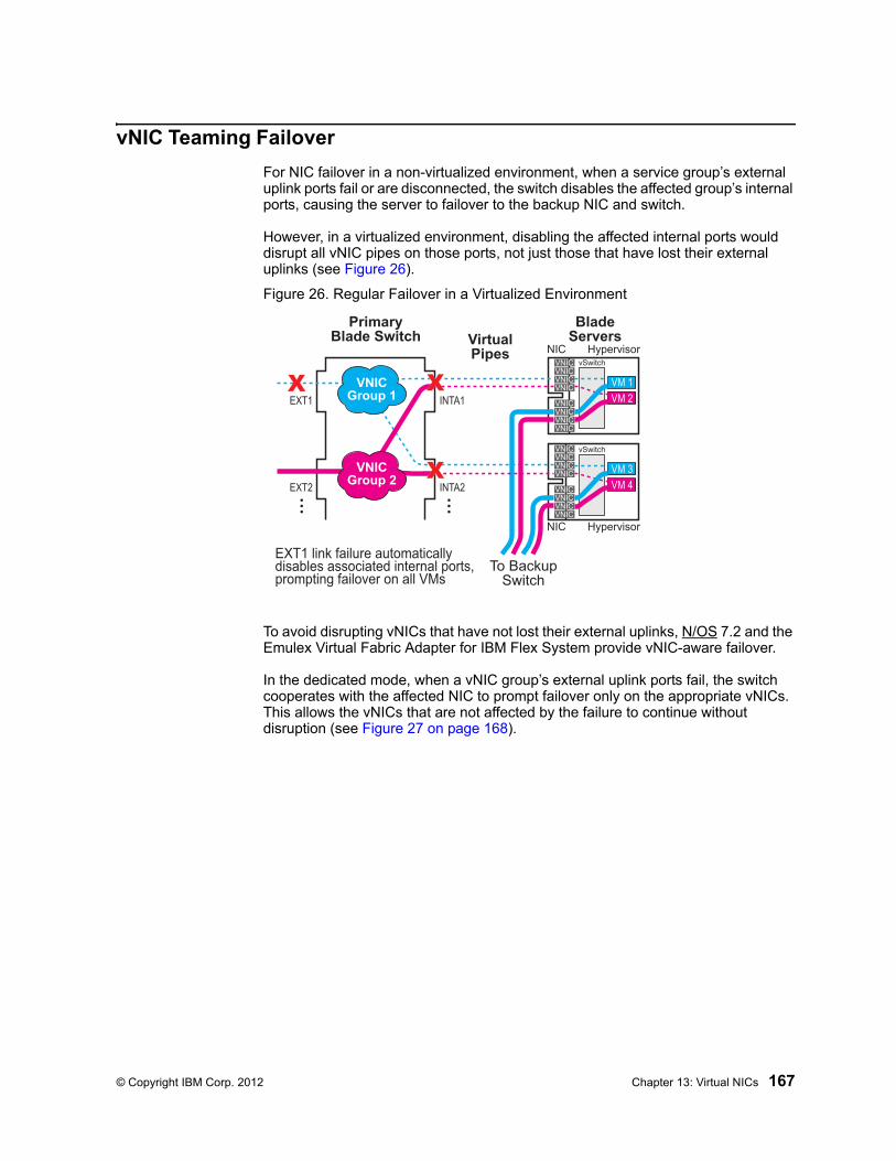
© Copyright IBM Corp. 2012 Chapter 13: Virtual NICs 167
vNIC Teaming Failover
For NIC failover in a non-virtualized environment, when a service group’s external uplink ports fail or are disconnected, the switch disables the affected group’s internal ports, causing the server to failover to the backup NIC and switch.
However, in a virtualized environment, disabling the affected internal ports would disrupt all vNIC pipes on those ports, not just those that have lost their external uplinks (see Figure 26).
Figure 26. Regular Failover in a Virtualized Environment
To avoid disrupting vNICs that have not lost their external uplinks, N/OS 7.2 and the Emulex Virtual Fabric Adapter for IBM Flex System provide vNIC-aware failover.
In the dedicated mode, when a vNIC group’s external uplink ports fail, the switch cooperates with the affected NIC to prompt failover only on the appropriate vNICs. This allows the vNICs that are not affected by the failure to continue without disruption (see Figure 27 on page 168).
HypervisorNICVNICVNICVNICVNIC
VNICVNICVNICVNIC vSwitch
VM 3VM 4
HypervisorNIC
VNICVNICVNICVNIC
VNICVNICVNICVNIC vSwitch
VM 1VM 2
BladeServers
EXT1
EXT2
INTA1
INTA2
VNICGroup 1
VNICGroup 2
X
PrimaryBlade Switch
To BackupSwitch
VirtualPipes
EXT1 link failure automaticallydisables associated internal ports,prompting failover on all VMs
X
X

168 EN4093 10Gb Scalable Switch: Application Guide
Figure 27. vNIC Failover Solution
By default, vNIC Teaming Failover is disabled on each vNIC group, but can be enabled or disabled independently for each vNIC group using the following commands:
>> # /cfg/virt/vnic/vnicgrp <group number> (Select a vNIC group)>> # failover ena|dis (Enable or disable vNIC failover)
HypervisorNICVNICVNICVNICVNIC
VNICVNICVNICVNIC vSwitch
VM 3VM 4
HypervisorNIC
VNICVNICVNICVNIC
VNICVNICVNICVNIC vSwitch
VM 1VM 2
BladeServers
EXT1
EXT2
INTA1
INTA2
VNICGroup 1
VNICGroup 2
X
PrimaryBlade Switch
To BackupSwitch
VirtualPipes
X
X
Upon EXT1 link failure, the switchinforms the server hypervisorfor failover on affected VNICs only
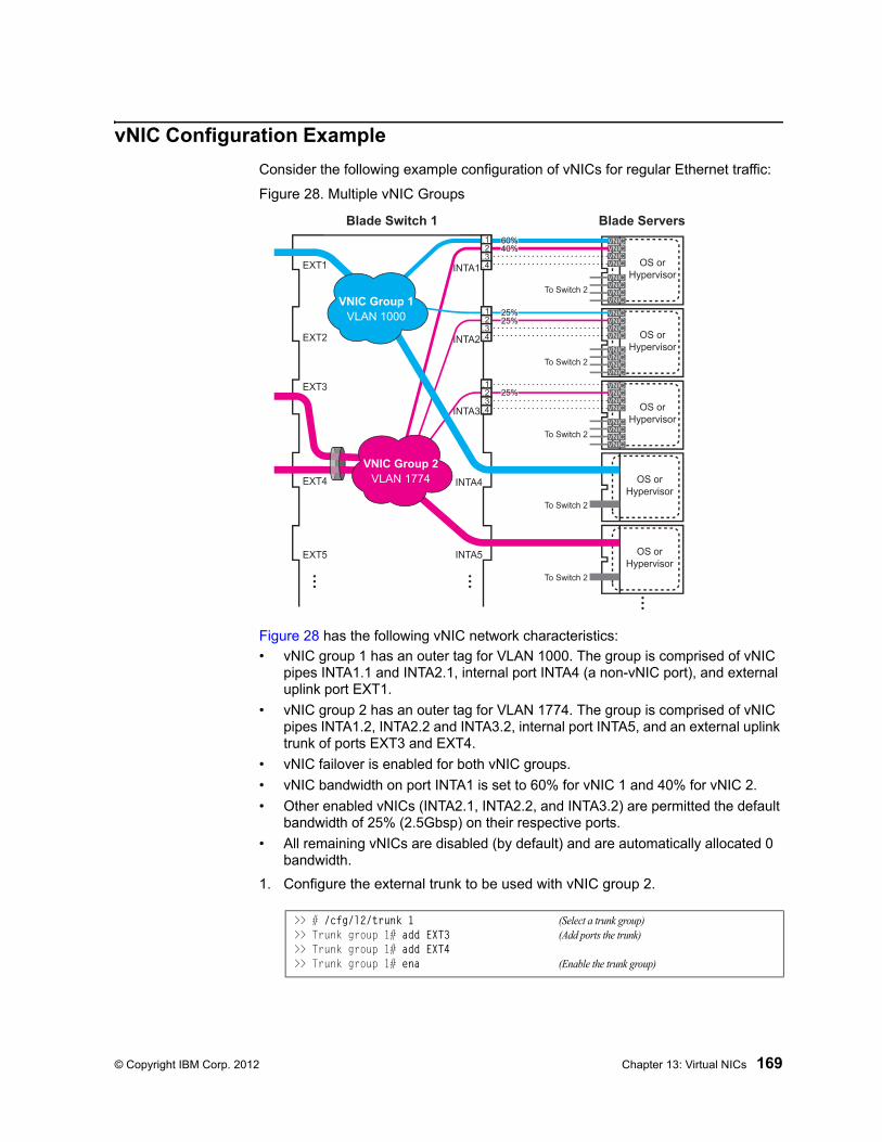
© Copyright IBM Corp. 2012 Chapter 13: Virtual NICs 169
vNIC Configuration Example
Consider the following example configuration of vNICs for regular Ethernet traffic:
Figure 28. Multiple vNIC Groups
Figure 28 has the following vNIC network characteristics:
• vNIC group 1 has an outer tag for VLAN 1000. The group is comprised of vNIC pipes INTA1.1 and INTA2.1, internal port INTA4 (a non-vNIC port), and external uplink port EXT1.
• vNIC group 2 has an outer tag for VLAN 1774. The group is comprised of vNIC pipes INTA1.2, INTA2.2 and INTA3.2, internal port INTA5, and an external uplink trunk of ports EXT3 and EXT4.
• vNIC failover is enabled for both vNIC groups.
• vNIC bandwidth on port INTA1 is set to 60% for vNIC 1 and 40% for vNIC 2.
• Other enabled vNICs (INTA2.1, INTA2.2, and INTA3.2) are permitted the default bandwidth of 25% (2.5Gbsp) on their respective ports.
• All remaining vNICs are disabled (by default) and are automatically allocated 0 bandwidth.
1. Configure the external trunk to be used with vNIC group 2.
>> # /cfg/l2/trunk 1 (Select a trunk group)>> Trunk group 1# add EXT3 (Add ports the trunk)>> Trunk group 1# add EXT4>> Trunk group 1# ena (Enable the trunk group)
OS orHypervisor
VNICVNICVNICVNIC
VNICVNICVNICVNIC
OS orHypervisor
VNICVNICVNICVNIC
VNICVNICVNICVNIC
OS orHypervisor
VNICVNICVNICVNIC
VNICVNICVNICVNIC
OS orHypervisor
OS orHypervisor
Blade Switch 1 Blade Servers
To Switch 2
To Switch 2
To Switch 2
To Switch 2
To Switch 2
EXT1
EXT2
EXT3
EXT4
EXT5
INTA1
INTA2
INTA3
INTA4
INTA5
.1
.2
.3
.4
.1
.2
.3
.4
.1
.2
.3
.4
60%40%
25%25%
25%
VNIC Group 1VLAN 1000
VNIC Group 2VLAN 1774
170 EN4093 10Gb Scalable Switch: Application Guide
2. Enable the vNIC feature on the switch.
3. Configure the virtual pipes for the vNICs attached to each internal port:
As a configuration shortcut, vNICs do not have to be explicitly enabled in this step. When a vNIC is added to the vNIC group (in the next step), the switch will prompt you to confirm automatically enabling the vNIC if it is not yet enabled (shown for INT3.2).
Note: vNICs are not supported simultaneously on the same switch ports as VMready.
4. Add ports, trunks, and virtual pipes to their vNIC groups.
Once VLAN 1000 and 1774 are configured for vNIC groups, they will not be available for configuration in the regular VLAN menus (/cfg/l2/vlan).
Note: vNICs are not supported simultaneously on the same switch ports as VMready.
5. Apply and save the configuration.
>> Trunk group 1# /cfg/virt/vnic/on
>> vNIC Global Configuration# port INTA1 (Select port INTA1)>> Port INT1 vNICs# vnic 1 (Select vNIC 1 on the port)>> vNIC INT1.1# ena (Enable the vNIC pipe)>> vNIC INT1.1# bw 60 (Allow 60% egress bandwidth)>> vNIC INT1.1# ../vnic 2 (Select vNIC 2 on the port)>> vNIC INT1.2# ena (Enable the vNIC pipe)>> vNIC INT1.2# bw 40 (Allow 40% egress bandwidth)
>> vNIC INT1.2# /cfg/virt/vnic/port INTA2 (Select port INTA2)>> Port INT2 vNICs# vnic 1 (Select vNIC 1 on the port)>> vNIC INT2.1# ena (Enable the vNIC pipe)>> vNIC INT2.1# ../vnic 2 (Select vNIC 2 on the port)>> vNIC INT2.2# ena (Enable the vNIC pipe)
>> vNIC INT3.1# /cfg/virt/vnic/vnicgrp 1 (Select vNIC group 1)>> vNIC Group 1# vnicvlan 1000 (Specify the VLAN)>> vNIC Group 1# addvnic INTA1.1 (Add vNIC pipes to the group)>> vNIC Group 1# addvnic INTA2.1>> vNIC Group 1# addport INTA4 (Add ports to the group)>> vNIC Group 1# addport EXT1>> vNIC Group 1# failover ena (Enable vNIC failover for the group)>> vNIC Group 1# ena (Enable the vNIC group)
>> vNIC Group 1# ../vnicgrp 2 (Select vNIC group 2)>> vNIC Group 2# vnicvlan 1774 (Specify the VLAN)>> vNIC Group 2# addvnic INTA1.2 (Add vNIC pipes to the group)>> vNIC Group 2# addvnic INTA2.2>> vNIC Group 2# addvnic INTA3.2vNIC INT3.1 is not enabled.Confirm enabling vNIC3.1 [y/n]: y (Shortcut to enable vNIC)>> vNIC Group 2# addport INTA5 (Add port INTA5 to the group)>> vNIC Group 2# addtrnk 1 (Add trunk group 1 to the group)>> vNIC Group 2# failover ena (Enable vNIC failover for the group)>> vNIC Group 2# ena (Enable the vNIC group)
© Copyright IBM Corp. 2012 Chapter 13: Virtual NICs 171
vNICs for iSCSI on Emulex Virtual Fabric Adapter
The N/OS vNIC feature works with standard network applications like iSCSI as previously described. However, the Emulex Virtual Fabric Adapter for IBM Flex System expects iSCSI traffic to occur only on a single vNIC pipe. When using the Emulex Adapter 2, only vNIC pipe 2 may participate in iSCSI.
To configure the switch for this solution, iSCSI traffic should be placed in its own vNIC group, comprised of the external uplink port leading to the iSCSI target, and the related <port>.2 vNIC pipes connected to the participating servers. For example:
1. Enable the vNIC feature on the switch.
2. Configure the virtual pipes for the iSCSI vNICs attached to each internal port:
Note: vNICs are not supported simultaneously on the same switch ports as VMready.
3. Add ports and virtual pipes to a vNIC group.
4. Apply and save the configuration.
>> # /cfg/virt/vnic/on
>> vNIC Global Configuration# port INTA1 (Select port INTA1)>> Port INT1 vNICs# vnic 2 (Select vNIC 1 on the port)>> vNIC INT1.2# ena (Enable the vNIC pipe)>> vNIC INT1.2# /cfg/virt/vnic/port INTA2 (Select port INTA2)>> vNIC INT2.2# ../vnic 2 (Select vNIC 2 on the port)>> vNIC INT2.2# ena (Enable the vNIC pipe)>> vNIC INT2.2# /cfg/virt/vnic/port INTA3 (Select port INTA3)>> vNIC INT3.2# ../vnic 2 (Select vNIC 2 on the port)>> vNIC INT3.2# ena (Enable the vNIC pipe)
>> vNIC INT3.2# /cfg/virt/vnic/vnicgrp 1 (Select vNIC group 1)>> vNIC Group 1# vnicvlan 1000 (Specify the VLAN)>> vNIC Group 1# addvnic INTA1.2 (Add iSCSI vNIC pipes to the group)>> vNIC Group 1# addvnic INTA2.2>> vNIC Group 1# addvnic INTA3.2>> vNIC Group 1# addport EXT1 (Add the uplink port to the group)>> vNIC Group 1# ena (Enable the vNIC group)

172 EN4093 10Gb Scalable Switch: Application Guide
© Copyright IBM Corp. 2012 173
Chapter 14. VMready
Virtualization is used to allocate server resources based on logical needs, rather than on strict physical structure. With appropriate hardware and software support, servers can be virtualized to host multiple instances of operating systems, known as virtual machines (VMs). Each VM has its own presence on the network and runs its own service applications.
Software known as a hypervisor manages the various virtual entities (VEs) that reside on the host server: VMs, virtual switches, and so on. Depending on the virtualization solution, a virtualization management server may be used to configure and manage multiple hypervisors across the network. With some solutions, VMs can even migrate between host hypervisors, moving to different physical hosts while maintaining their virtual identity and services.
The IBM Networking OS 7.2 VMready feature supports up to 2048 VEs in a virtualized data center environment. The switch automatically discovers the VEs attached to switch ports, and distinguishes between regular VMs, Service Console
Interfaces, and Kernel/Management Interfaces in a VMware® environment.
VEs may be placed into VM groups on the switch to define communication boundaries: VEs in the same VM group may communicate with each other, while VEs in different groups may not. VM groups also allow for configuring group-level settings such as virtualization policies and ACLs.
The administrator can also pre-provision VEs by adding their MAC addresses (or their IPv4 address or VM name in a VMware environment) to a VM group. When a VE with a pre-provisioned MAC address becomes connected to the switch, the switch will automatically apply the appropriate group membership configuration.
The EN4093 with VMready also detects the migration of VEs across different
hypervisors. As VEs move, the EN4093 NMotion™ feature automatically moves the appropriate network configuration as well. NMotion gives the switch the ability to maintain assigned group membership and associated policies, even when a VE moves to a different port on the switch.
VMready also works with VMware Virtual Center (vCenter) management software. Connecting with a vCenter allows the EN4093 to collect information about more distant VEs, synchronize switch and VE configuration, and extend migration properties.
174 EN4093 10Gb Scalable Switch: Application Guide
VE Capacity
When VMready is enabled, the switch will automatically discover VEs that reside in hypervisors directly connected on the switch ports. IBM Networking OS 7.2 supports up to 2048 VEs. Once this limit is reached, the switch will reject additional VEs.
Note: In rare situations, the switch may reject new VEs prior to reaching the supported limit. This can occur when the internal hash corresponding to the new VE is already in use. If this occurs, change the MAC address of the VE and retry the operation. The MAC address can usually be changed from the virtualization management server console (such as the VMware Virtual Center).
VM Group Types
VEs, as well as internal ports, external ports, static trunks and LACP trunks, can be placed into VM groups on the switch to define virtual communication boundaries. Elements in a given VM group are permitted to communicate with each other, while those in different groups are not. The elements within a VM group automatically share certain group-level settings.
IBM Networking OS 7.2 supports up to 32 VM groups. There are two different types:
• Local VM groups are maintained locally on the switch. Their configuration is not synchronized with hypervisors.
• Distributed VM groups are automatically synchronized with a virtualization man-agement server (see “Assigning a vCenter” on page 181).
Each VM group type is covered in detail in the following sections.
Local VM Groups
The configuration for local VM groups is maintained on the switch (locally) and is not directly synchronized with hypervisors. Local VM groups may include only local elements: local switch ports and trunks, and only those VEs connected to one of the switch ports or pre-provisioned on the switch.
Local VM groups support limited VE migration: as VMs and other VEs move to different hypervisors connected to different ports on the switch, the configuration of their group identity and features moves with them. However, VE migration to and from more distant hypervisors (those not connected to the EN4093, may require manual configuration when using local VM groups.
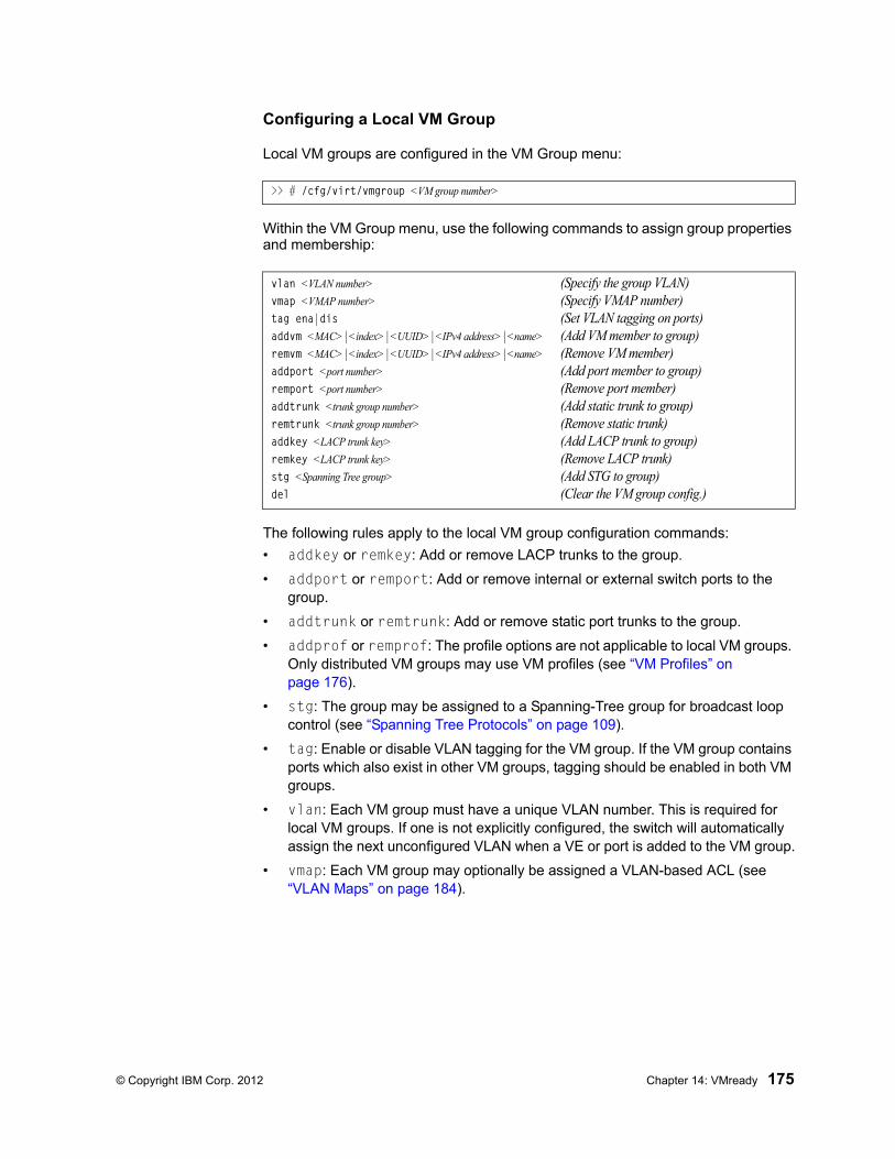
© Copyright IBM Corp. 2012 Chapter 14: VMready 175
Configuring a Local VM Group
Local VM groups are configured in the VM Group menu:
Within the VM Group menu, use the following commands to assign group properties and membership:
The following rules apply to the local VM group configuration commands:
• addkey or remkey: Add or remove LACP trunks to the group.
• addport or remport: Add or remove internal or external switch ports to the group.
• addtrunk or remtrunk: Add or remove static port trunks to the group.
• addprof or remprof: The profile options are not applicable to local VM groups. Only distributed VM groups may use VM profiles (see “VM Profiles” on page 176).
• stg: The group may be assigned to a Spanning-Tree group for broadcast loop control (see “Spanning Tree Protocols” on page 109).
• tag: Enable or disable VLAN tagging for the VM group. If the VM group contains ports which also exist in other VM groups, tagging should be enabled in both VM groups.
• vlan: Each VM group must have a unique VLAN number. This is required for local VM groups. If one is not explicitly configured, the switch will automatically assign the next unconfigured VLAN when a VE or port is added to the VM group.
• vmap: Each VM group may optionally be assigned a VLAN-based ACL (see “VLAN Maps” on page 184).
>> # /cfg/virt/vmgroup <VM group number>
vlan <VLAN number> (Specify the group VLAN)vmap <VMAP number> (Specify VMAP number)tag ena|dis (Set VLAN tagging on ports)addvm <MAC>|<index>|<UUID>|<IPv4 address>|<name> (Add VM member to group)remvm <MAC>|<index>|<UUID>|<IPv4 address>|<name> (Remove VM member)addport <port number> (Add port member to group)remport <port number> (Remove port member)addtrunk <trunk group number> (Add static trunk to group)remtrunk <trunk group number> (Remove static trunk)addkey <LACP trunk key> (Add LACP trunk to group)remkey <LACP trunk key> (Remove LACP trunk)stg <Spanning Tree group> (Add STG to group)del (Clear the VM group config.)
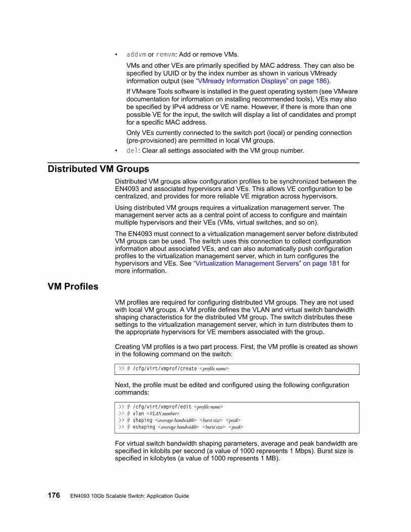
176 EN4093 10Gb Scalable Switch: Application Guide
• addvm or remvm: Add or remove VMs.
VMs and other VEs are primarily specified by MAC address. They can also be specified by UUID or by the index number as shown in various VMready information output (see “VMready Information Displays” on page 186).
If VMware Tools software is installed in the guest operating system (see VMware documentation for information on installing recommended tools), VEs may also be specified by IPv4 address or VE name. However, if there is more than one possible VE for the input, the switch will display a list of candidates and prompt for a specific MAC address.
Only VEs currently connected to the switch port (local) or pending connection (pre-provisioned) are permitted in local VM groups.
• del: Clear all settings associated with the VM group number.
Distributed VM GroupsDistributed VM groups allow configuration profiles to be synchronized between the EN4093 and associated hypervisors and VEs. This allows VE configuration to be centralized, and provides for more reliable VE migration across hypervisors.
Using distributed VM groups requires a virtualization management server. The management server acts as a central point of access to configure and maintain multiple hypervisors and their VEs (VMs, virtual switches, and so on).
The EN4093 must connect to a virtualization management server before distributed VM groups can be used. The switch uses this connection to collect configuration information about associated VEs, and can also automatically push configuration profiles to the virtualization management server, which in turn configures the hypervisors and VEs. See “Virtualization Management Servers” on page 181 for more information.
VM Profiles
VM profiles are required for configuring distributed VM groups. They are not used with local VM groups. A VM profile defines the VLAN and virtual switch bandwidth shaping characteristics for the distributed VM group. The switch distributes these settings to the virtualization management server, which in turn distributes them to the appropriate hypervisors for VE members associated with the group.
Creating VM profiles is a two part process. First, the VM profile is created as shown in the following command on the switch:
Next, the profile must be edited and configured using the following configuration commands:
For virtual switch bandwidth shaping parameters, average and peak bandwidth are specified in kilobits per second (a value of 1000 represents 1 Mbps). Burst size is specified in kilobytes (a value of 1000 represents 1 MB).
>> # /cfg/virt/vmprof/create <profile name>
>> # /cfg/virt/vmprof/edit <profile name>>> # vlan <VLAN number>>> # shaping <average bandwidth> <burst size> <peak>>> # eshaping <average bandwidth> <burst size> <peak>

© Copyright IBM Corp. 2012 Chapter 14: VMready 177
Note: The bandwidth shaping parameters in the VM profile are used by the hypervisor virtual switch software. To set bandwidth policies for individual VEs, see “VM Policy Bandwidth Control” on page 185.
Once configured, the VM profile may be assigned to a distributed VM group as shown in the following section.
Initializing a Distributed VM Group
Note: A VM profile is required before a distributed VM group may be configured. See “VM Profiles” on page 176 for details.
Once a VM profile is available, a distributed VM group may be initialized using the following configuration command:
Only one VM profile can be assigned to a given distributed VM group. To change the VM profile, the old one must first be removed.
Note: The VM profile can be added only to an empty VM group (one that has no VLAN, VMs, or port members). Any VM group number currently configured for a local VM group (see “Local VM Groups” on page 174) cannot be converted and must be deleted before it can be used for a distributed VM group.
Assigning Members
VMs, ports, and trunks may be added to the distributed VM group only after the VM profile is assigned. Group members are added, pre-provisioned, or removed from distributed VM groups in the same manner as with local VM groups (“Local VM Groups” on page 174), with the following exceptions:
• VMs: VMs and other VEs are not required to be local. Any VE known by the virtualization management server can be part of a distributed VM group.
• The VM group vlan option (see page 175) cannot be used with distributed VM groups. For distributed VM groups, the VLAN is assigned in the VM profile.
Synchronizing the Configuration
When the configuration for a distributed VM group is applied (using the CLI apply command), the switch updates the assigned virtualization management server. The management server then distributes changes to the appropriate hypervisors.
For VM membership changes, hypervisors modify their internal virtual switch port groups, adding or removing internal port memberships to enforce the boundaries defined by the distributed VM groups. Virtual switch port groups created in this fashion can be identified in the virtual management server by the name of the VM profile, formatted as follows:
BNT_<VM profile name>
Using the VM Group menu addvm command (/cfg/virt/vmgroup <x>/addvm) to add a server host interface to a distributed VM group does not create a new port group on the virtual switch or move the host. Instead, because the host interface already has its own virtual switch port group on the hypervisor, the VM profile settings are applied to its existing port group.
>> # /cfg/virt/vmgroup <VM group number>/addprof <VM profile name>
178 EN4093 10Gb Scalable Switch: Application Guide
Note: When applying the distributed VM group configuration, the virtualization management server and associated hypervisors must take appropriate actions. If a hypervisor is unable to make requested changes, an error message will be displayed on the switch. Be sure to evaluate all error message and take the appropriate actions to be sure the expected changes are properly applied.
Removing Member VEs
Removing a VE from a distributed VM group on the switch will have the following effects on the hypervisor:
• The VE will be moved to the BNT_Default port group in VLAN 0 (zero).
• Traffic shaping will be disabled for the VE.
• All other properties will be reset to default values inherited from the virtual switch.
© Copyright IBM Corp. 2012 Chapter 14: VMready 179
Virtual Distributed Switch
A virtual Distributed Switch (vDS) allows the hypervisor’s NIC to be attached to the vDS instead of its own virtual switch. The vDS connects to the vCenter and spans across multiple hypervisors in a datacenter. The administrator can manage virtual machine networking for the entire data center from a single interface. The vDS enables centralized provisioning and administration of virtual machine networking in the data center using the VMware vCenter server.
When a member is added to a distributed VM group, a distributed port group is created on the vDS. The member is then added to the distributed port group.
Distributed port groups on a vDS are available to all hypervisors that are connected to the vDS. Members of a single distributed port group can communicate with each other.
Note: vDS works with ESX 4.0 or higher versions.
To add a vDS, use the command:
Prerequisites
Before adding a vDS on the EN4093, ensure the following:
• VMware vCenter is fully installed and configured and includes a “bladevm” administration account and a valid SSL certificate.
• A virtual distributed switch instance has been created on the vCenter. The vDS version must be higher or the same as the hypervisor version on the hosts.
• At least two hypervisors are configured.
Guidelines
Before migrating VMs to a vDS, consider the following:
• At any one time, a VM NIC can be associated with only one virtual switch: to the hypervisor’s virtual switch, or to the vDS.
• Management connection to the server must be ensured during the migration. The connection is via the Service Console or the Kernel/Management Interface.
• The vDS configuration and migration can be viewed in vCenter at the following locations:
– vDS: Home> Inventory > Networking– vDS Hosts: Home > Inventory > Networking > vDS > Hosts
Note: These changes will not be displayed in the running configuration on the EN4093.
Migrating to vDS
You can migrate VMs to the vDS using vCenter. The migration may also be accomplished using the operational commands on the EN4093 available in the following CLI menus:
>> # /oper/virt/vmware/dvswitch/add <datacenter-name> <dvSwitch-name> <dvSwitch-version>

180 EN4093 10Gb Scalable Switch: Application Guide
For VMware vDS operations:
For VMware distributed port group operations:
>> # /oper/virt/vmware/dvswitch
>> # /oper/virt/vmware/dpg
© Copyright IBM Corp. 2012 Chapter 14: VMready 181
Virtualization Management ServersThe EN4093 can connect with a virtualization management server to collect configuration information about associated VEs. The switch can also automatically push VM group configuration profiles to the virtualization management server, which in turn configures the hypervisors and VEs, providing enhanced VE mobility.
One virtual management server must be assigned on the switch before distributed VM groups may be used. IBM Networking OS 7.2 currently supports only the VMware Virtual Center (vCenter).
Assigning a vCenter
Assigning a vCenter to the switch requires the following:
• The vCenter must have a valid IPv4 address which is accessible to the switch (IPv6 addressing is not supported for the vCenter).
• A user account must be configured on the vCenter to provide access for the switch. The account must have (at a minimum) the following vCenter user privi-leges:– Network
– Host Network > Configuration
– Virtual Machine > Modify Device Settings
Once vCenter requirements are met, the following configuration command can be used on the EN4093 to associate the vCenter with the switch:
This command specifies the IPv4 address and account username that the switch will use for vCenter access. Once entered, the administrator will be prompted to enter the password for the specified vCenter account.
The noauth option causes to the switch to ignores SSL certificate authentication. This is required when no authoritative SSL certificate is installed on the vCenter.
Note: By default, the vCenter includes only a self-signed SSL certificate. If using the default certificate, the noauth option is required.
Once the vCenter configuration has been applied on the switch, the EN4093 will connect to the vCenter to collect VE information.
vCenter Scans
Once the vCenter is assigned, the switch will periodically scan the vCenter to collect basic information about all the VEs in the datacenter, and more detailed information about the local VEs that the switch has discovered attached to its own ports.
The switch completes a vCenter scan approximately every two minutes. Any major changes made through the vCenter may take up to two minutes to be reflected on the switch. However, you can force an immediate scan of the vCenter by using one of the following commands:
>> # /cfg/virt/vmware/vcspec <vCenter IPv4 address> <username> [noauth]
>> # /oper/virt/vmware/scan (Scan the vCenter)
-or-
>> # /info/virt/vm/dump -v -r (Scan vCenter and display result)
182 EN4093 10Gb Scalable Switch: Application Guide
Deleting the vCenter
To detach the vCenter from the switch, use the following configuration command:
Note: Without a valid vCenter assigned on the switch, any VE configuration changes must be manually synchronized.
Deleting the assigned vCenter prevents synchronizing the configuration between the EN4093 and VEs. VEs already operating in distributed VM groups will continue to function as configured, but any changes made to any VM profile or distributed VM group on the switch will affect only switch operation; changes on the switch will not be reflected in the vCenter or on the VEs. Likewise, any changes made to VE configuration on the vCenter will no longer be reflected on the switch.
Exporting Profiles
VM profiles for discovered VEs in distributed VM groups are automatically synchronized with the virtual management server and the appropriate hypervisors. However, VM profiles can also be manually exported to specific hosts before individual VEs are defined on them.
By exporting VM profiles to a specific host, BNT port groups will be available to the host’s internal virtual switches so that new VMs may be configured to use them.
VM migration requires that the target hypervisor includes all the virtual switch port groups to which the VM connects on the source hypervisor. The VM profile export feature can be used to distribute the associated port groups to all the potential hosts for a given VM.
A VM profile can be exported to a host using the following command:
The host list can include one or more target hosts, specified by host name, IPv4 address, or UUID, with each list item separated by a space. If the virtual switch name is omitted, the administrator will be prompted to select one from a list or to enter a new virtual switch name.
Once executed, the requisite port group will be created on the specified virtual switch. If the specified virtual switch does not exist on the target host, it will be created with default properties, but with no uplink connection to a physical NIC (the administrator must assign uplinks using VMware management tools.
VMware Operational Commands
The EN4093 may be used as a central point of configuration for VMware virtual switches and port groups using the VMware operational menu, available with the following CLI command:
>> # /cfg/virt/vmware/vcspec delete
>> # /oper/virt/vmware/export <VM profile name> <host list> [<virtual switch name>]
>> # /oper/virt/vmware
© Copyright IBM Corp. 2012 Chapter 14: VMready 183
Pre-Provisioning VEs
VEs may be manually added to VM groups in advance of being detected on the switch ports. By pre-provisioning the MAC address of VEs that are not yet active, the switch will be able to later recognize the VE when it becomes active on a switch port, and immediately assign the proper VM group properties without further configuration.
Undiscovered VEs are added to or removed from VM groups using the following configuration commands:
For the pre-provisioning of undiscovered VEs, a MAC address is required. Other identifying properties, such as IPv4 address or VM name permitted for known VEs, cannot be used for pre-provisioning.
>> # /cfg/virt/vmgroup <VM group number> (Select VM group)>> # addvm <VE MAC address> (Add undiscovered VE)>> # remvm <VE MAC address> (Remove VE)
184 EN4093 10Gb Scalable Switch: Application Guide
VLAN Maps
A VLAN map (VMAP) is a type of Access Control List (ACL) that is applied to a VLAN or VM group rather than to a switch port as with regular ACLs (see “Access Control Lists” on page 65). In a virtualized environment, VMAPs allow you to create traffic filtering and metering policies that are associated with a VM group VLAN, allowing filters to follow VMs as they migrate between hypervisors.
VMAPs are configured from the ACL menu, available with the following CLI command:
IBM Networking OS 7.2 supports up to 128 VMAPs. Individual VMAP filters are configured in the same fashion as regular ACLs, except that VLANs cannot be specified as a filtering criteria (unnecessary, since VMAPs are assigned to a specific VLAN or associated with a VM group VLAN).
Once a VMAP filter is created, it can be assigned or removed using the following commands:
• For a regular VLAN:
• For a VM group:
Note: Each VMAP can be assigned to only one VLAN or VM group. However, each VLAN or VM group may have multiple VMAPs assigned to it.
The optional intports or extports parameter can be specified to apply the action (to add or remove the VMAP) for either the internal ports or external ports only. If omitted, the operation will be applied to all ports in the associated VLAN or VM group.
Note: VMAPs have a lower priority than port-based ACLs. If both an ACL and a VMAP match a particular packet, both filter actions will be applied as long as there is no conflict. In the event of a conflict, the port ACL will take priority, though switch statistics will count matches for both the ACL and VMAP.
# /cfg/acl/vmap <VMAP ID (1-128)>
/cfg/l2/vlan <VLAN ID>/vmap {add|rem} <VMAP ID> [intports|extports]
/cfg/virt/vmgroup <ID>/vmap {add|rem} <VMAP ID> [intports|extports]

© Copyright IBM Corp. 2012 Chapter 14: VMready 185
VM Policy Bandwidth ControlIn a virtualized environment where VEs can migrate between hypervisors and thus move among different ports on the switch, traffic bandwidth policies must be attached to VEs, rather than to a specific switch port.
VM Policy Bandwidth Control allows the administrator to specify the amount of data the switch will permit to flow to or from a particular VE, without defining a complicated matrix of ACLs or VMAPs for all port combinations where a VE may appear.
VM Policy Bandwidth Control Commands
VM Policy Bandwidth Control can be configured using the following configuration commands:
Bandwidth allocation can be defined either for transmit (TX) traffic or receive (RX) traffic. Because bandwidth allocation is specified from the perspective of the VE, the switch command for TX Rate Control (txrate) sets the data rate to be sent from the VM to the switch, and the RX Rate Control (rxrate) sets the data rate to be received by the VM from the switch.
The committed rate is specified in multiples of 64 kbps, from 64 to 10,000,000. The maximum burst rate is specified as 32, 64, 128, 256, 1024, 2048, or 4096 kb. If both the committed rate and burst are set to 0, bandwidth control in that direction (TX or RX) will be disabled.
When txrate is specified, the switch automatically selects an available ACL for internal use with bandwidth control. Optionally, if automatic ACL selection is not desired, a specific ACL may be selected. If there are no unassigned ACLs available, txrate cannot be configured.
# /cfg/virt/vmpolicy/vmbwidth <VM MAC>|<index>|<UUID>|<IPv4 address>|<name>
# txrate <committed rate> <burst> [<ACL number>] (Set the VM to switch rate)# rxrate <committed rate> <burst> (Set the switch to VM rate)# bwctrl {ena|dis} (Set control on or off for VM)# delete (Clear settings)
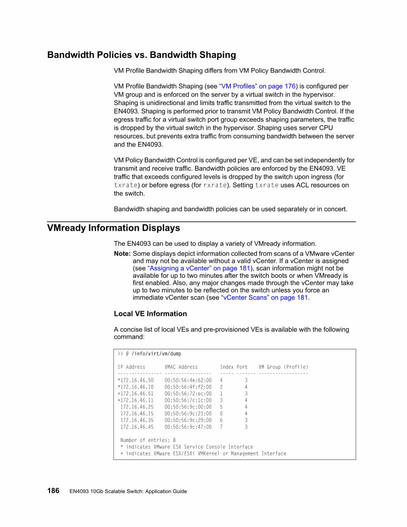
186 EN4093 10Gb Scalable Switch: Application Guide
Bandwidth Policies vs. Bandwidth Shaping
VM Profile Bandwidth Shaping differs from VM Policy Bandwidth Control.
VM Profile Bandwidth Shaping (see “VM Profiles” on page 176) is configured per VM group and is enforced on the server by a virtual switch in the hypervisor. Shaping is unidirectional and limits traffic transmitted from the virtual switch to the EN4093. Shaping is performed prior to transmit VM Policy Bandwidth Control. If the egress traffic for a virtual switch port group exceeds shaping parameters, the traffic is dropped by the virtual switch in the hypervisor. Shaping uses server CPU resources, but prevents extra traffic from consuming bandwidth between the server and the EN4093.
VM Policy Bandwidth Control is configured per VE, and can be set independently for transmit and receive traffic. Bandwidth policies are enforced by the EN4093. VE traffic that exceeds configured levels is dropped by the switch upon ingress (for txrate) or before egress (for rxrate). Setting txrate uses ACL resources on the switch.
Bandwidth shaping and bandwidth policies can be used separately or in concert.
VMready Information Displays
The EN4093 can be used to display a variety of VMready information.
Note: Some displays depict information collected from scans of a VMware vCenter and may not be available without a valid vCenter. If a vCenter is assigned (see “Assigning a vCenter” on page 181), scan information might not be available for up to two minutes after the switch boots or when VMready is first enabled. Also, any major changes made through the vCenter may take up to two minutes to be reflected on the switch unless you force an immediate vCenter scan (see “vCenter Scans” on page 181.
Local VE Information
A concise list of local VEs and pre-provisioned VEs is available with the following command:
>> # /info/virt/vm/dump
IP Address VMAC Address Index Port VM Group (Profile)---------------- ----------------- ----- ------- ------------------*172.16.46.50 00:50:56:4e:62:00 4 3*172.16.46.10 00:50:56:4f:f2:00 2 4+172.16.46.51 00:50:56:72:ec:00 1 3+172.16.46.11 00:50:56:7c:1c:00 3 4 172.16.46.25 00:50:56:9c:00:00 5 4 172.16.46.15 00:50:56:9c:21:00 0 4 172.16.46.35 00:50:56:9c:29:00 6 3 172.16.46.45 00:50:56:9c:47:00 7 3
Number of entries: 8 * indicates VMware ESX Service Console Interface + indicates VMware ESX/ESXi VMKernel or Management Interface
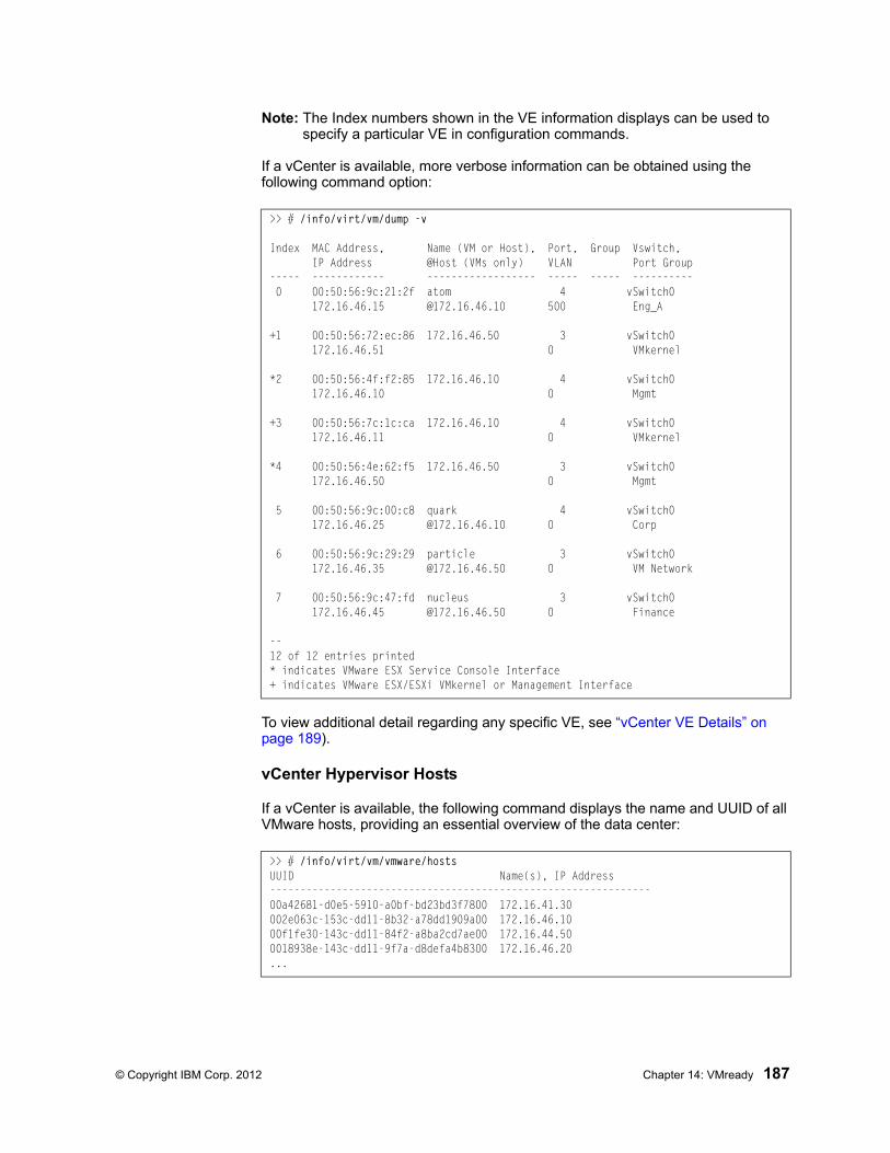
© Copyright IBM Corp. 2012 Chapter 14: VMready 187
Note: The Index numbers shown in the VE information displays can be used to specify a particular VE in configuration commands.
If a vCenter is available, more verbose information can be obtained using the following command option:
To view additional detail regarding any specific VE, see “vCenter VE Details” on page 189).
vCenter Hypervisor Hosts
If a vCenter is available, the following command displays the name and UUID of all VMware hosts, providing an essential overview of the data center:
>> # /info/virt/vm/dump -v
Index MAC Address, Name (VM or Host), Port, Group Vswitch, IP Address @Host (VMs only) VLAN Port Group----- ------------ ------------------ ----- ----- ---------- 0 00:50:56:9c:21:2f atom 4 vSwitch0 172.16.46.15 @172.16.46.10 500 Eng_A
+1 00:50:56:72:ec:86 172.16.46.50 3 vSwitch0 172.16.46.51 0 VMkernel
*2 00:50:56:4f:f2:85 172.16.46.10 4 vSwitch0 172.16.46.10 0 Mgmt
+3 00:50:56:7c:1c:ca 172.16.46.10 4 vSwitch0 172.16.46.11 0 VMkernel
*4 00:50:56:4e:62:f5 172.16.46.50 3 vSwitch0 172.16.46.50 0 Mgmt
5 00:50:56:9c:00:c8 quark 4 vSwitch0 172.16.46.25 @172.16.46.10 0 Corp
6 00:50:56:9c:29:29 particle 3 vSwitch0 172.16.46.35 @172.16.46.50 0 VM Network
7 00:50:56:9c:47:fd nucleus 3 vSwitch0 172.16.46.45 @172.16.46.50 0 Finance
--12 of 12 entries printed* indicates VMware ESX Service Console Interface+ indicates VMware ESX/ESXi VMkernel or Management Interface
>> # /info/virt/vm/vmware/hostsUUID Name(s), IP Address---------------------------------------------------------------00a42681-d0e5-5910-a0bf-bd23bd3f7800 172.16.41.30002e063c-153c-dd11-8b32-a78dd1909a00 172.16.46.1000f1fe30-143c-dd11-84f2-a8ba2cd7ae00 172.16.44.500018938e-143c-dd11-9f7a-d8defa4b8300 172.16.46.20...
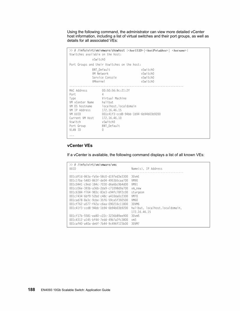
188 EN4093 10Gb Scalable Switch: Application Guide
Using the following command, the administrator can view more detailed vCenter host information, including a list of virtual switches and their port groups, as well as details for all associated VEs:
vCenter VEs
If a vCenter is available, the following command displays a list of all known VEs:
>> # /info/virt/vm/vmware/showhost {<host UUID>|<host IPv4 address>| <host name>}Vswitches available on the host:
vSwitch0
Port Groups and their Vswitches on the host:
BNT_Default vSwitch0 VM Network vSwitch0 Service Console vSwitch0 VMkernel vSwitch0
----------------------------------------------------------------------MAC Address 00:50:56:9c:21:2fPort 4Type Virtual MachineVM vCenter Name halibutVM OS hostname localhost.localdomainVM IP Address 172.16.46.15VM UUID 001c41f3-ccd8-94bb-1b94-6b94b03b9200Current VM Host 172.16.46.10Vswitch vSwitch0Port Group BNT_DefaultVLAN ID 0
...
>> # /info/virt/vm/vmware/vmsUUID Name(s), IP Address----------------------------------------------------------------------001cdf1d-863a-fa5e-58c0-d197ed3e3300 30vm1001c1fba-5483-863f-de04-4953b5caa700 VM90001c0441-c9ed-184c-7030-d6a6bc9b4d00 VM91001cc06e-393b-a36b-2da9-c71098d9a700 vm_new001c6384-f764-983c-83e3-e94fc78f2c00 sturgeon001c7434-6bf9-52bd-c48c-a410da0c2300 VM70001cad78-8a3c-9cbe-35f6-59ca5f392500 VM60001cf762-a577-f42a-c6ea-090216c11800 30VM6001c41f3-ccd8-94bb-1b94-6b94b03b9200 halibut, localhost.localdomain, 172.16.46.15001cf17b-5581-ea80-c22c-3236b89ee900 30vm5001c4312-a145-bf44-7edd-49b7a2fc3800 vm3001caf40-a40a-de6f-7b44-9c496f123b00 30VM7
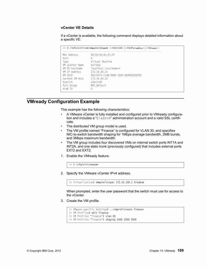
© Copyright IBM Corp. 2012 Chapter 14: VMready 189
vCenter VE Details
If a vCenter is available, the following command displays detailed information about a specific VE:
VMready Configuration Example
This example has the following characteristics:
• A VMware vCenter is fully installed and configured prior to VMready configura-tion and includes a “bladevm” administration account and a valid SSL certifi-cate.
• The distributed VM group model is used.• The VM profile named “Finance” is configured for VLAN 30, and specifies
NIC-to-switch bandwidth shaping for 1Mbps average bandwidth, 2MB bursts, and 3Mbps maximum bandwidth.
• The VM group includes four discovered VMs on internal switch ports INT1A and INT2A, and one static trunk (previously configured) that includes external ports EXT2 and EXT2.
1. Enable the VMready feature.
2. Specify the VMware vCenter IPv4 address.
When prompted, enter the user password that the switch must use for access to the vCenter.
3. Create the VM profile.
>> # /info/virt/vm/vmware/showvm {<VM UUID>|<VM IPv4 address>|<VM name>}----------------------------------------------------------------------MAC Address 00:50:56:9c:21:2fPort 4Type Virtual MachineVM vCenter Name halibutVM OS hostname localhost.localdomainVM IP Address 172.16.46.15VM UUID 001c41f3-ccd8-94bb-1b94-6b94b03b9200Current VM Host 172.16.46.10Vswitch vSwitch0Port Group BNT_DefaultVLAN ID 0
>> # /cfg/virt/enavmr
>> Virtualization# vmware/vcspec 172.16.100.1 bladevm
>> VMware-specific Settings# ../vmprof/create Finance>> VM Profiles# edit Finance>> VM Profiles "Finance"# vlan 30>> VM Profiles "Finance"# shaping 1000 2000 3000

190 EN4093 10Gb Scalable Switch: Application Guide
4. Define the VM group.
When VMs are added, the internal server ports on which they appear are automatically added to the VM group. In this example, there is no need to manually add ports EXT1 and EXT2.
5. If necessary, enable VLAN tagging for the VM group:
Note: If the VM group contains ports which also exist in other VM groups, tagging should be enabled in both VM groups. In this example configuration, no ports exist in more than VM group.
6. Apply and save the configuration.
>> VM Profiles "Finance"# ../../vmgroup 1>> VM group 1# addprof Finance>> VM group 1# addvm arctic>> VM group 1# addvm monster>> VM group 1# addvm sierra>> VM group 1# addvm 00:50:56:4f:f2:00>> VM group 1# addport 1>> VM group 1# addport 3>> VM group 1# addtrunk 1
>> VM group 1# tag ena
>> VM group 1# apply>> VM group 1# save
© Copyright IBM Corp. 2012 191
Part 5: IP RoutingThis section discusses Layer 3 switching functions. In addition to switching traffic at near line rates, the application switch can perform multi-protocol routing. This section discusses basic routing and advanced routing protocols:
• Basic Routing
• IPv6 Host Management
• Routing Information Protocol (RIP)
• Internet Group Management Protocol (IGMP)
• Border Gateway Protocol (BGP)
• Open Shortest Path First (OSPF)

192 EN4093 10Gb Scalable Switch: Application Guide
© Copyright IBM Corp. 2012 193
Chapter 15. Basic IP Routing
This chapter provides configuration background and examples for using the EN4093 10Gb Scalable Switch (EN4093) to perform IP routing functions. The following topics are addressed in this chapter:
• “IP Routing Benefits” on page 193
• “Routing Between IP Subnets” on page 194
• “Subnet Routing Example” on page 196
• “Dynamic Host Configuration Protocol” on page 201
IP Routing Benefits
The EN4093 uses a combination of configurable IP switch interfaces and IP routing options. The switch IP routing capabilities provide the following benefits:
• Connects the server IP subnets to the rest of the backbone network.
• Provides the ability to route IP traffic between multiple Virtual Local Area Networks (VLANs) configured on the switch.
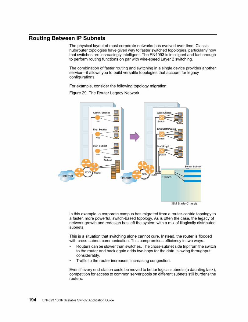
194 EN4093 10Gb Scalable Switch: Application Guide
Routing Between IP SubnetsThe physical layout of most corporate networks has evolved over time. Classic hub/router topologies have given way to faster switched topologies, particularly now that switches are increasingly intelligent. The EN4093 is intelligent and fast enough to perform routing functions on par with wire-speed Layer 2 switching.
The combination of faster routing and switching in a single device provides another service—it allows you to build versatile topologies that account for legacy configurations.
For example, consider the following topology migration:
Figure 29. The Router Legacy Network
In this example, a corporate campus has migrated from a router-centric topology to a faster, more powerful, switch-based topology. As is often the case, the legacy of network growth and redesign has left the system with a mix of illogically distributed subnets.
This is a situation that switching alone cannot cure. Instead, the router is flooded with cross-subnet communication. This compromises efficiency in two ways:
• Routers can be slower than switches. The cross-subnet side trip from the switch to the router and back again adds two hops for the data, slowing throughput considerably.
• Traffic to the router increases, increasing congestion.
Even if every end-station could be moved to better logical subnets (a daunting task), competition for access to common server pools on different subnets still burdens the routers.
InternetInternetInternetInternet
IBM Blade Chassis
Switch
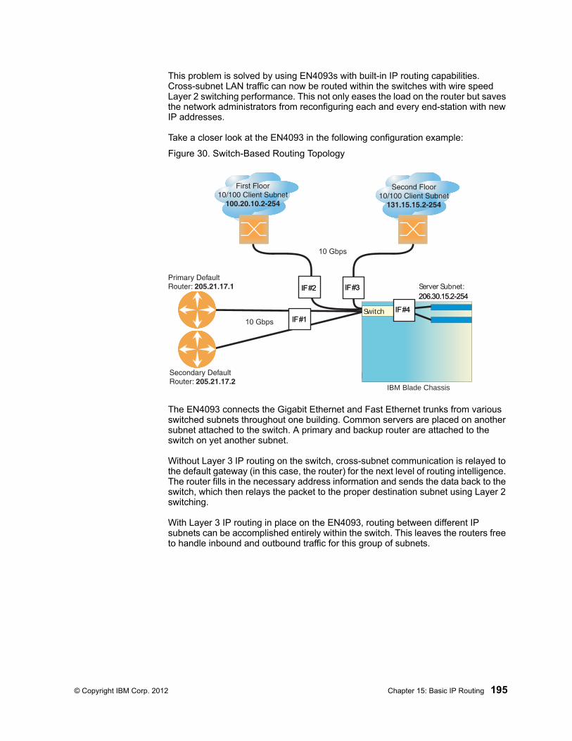
© Copyright IBM Corp. 2012 Chapter 15: Basic IP Routing 195
This problem is solved by using EN4093s with built-in IP routing capabilities. Cross-subnet LAN traffic can now be routed within the switches with wire speed Layer 2 switching performance. This not only eases the load on the router but saves the network administrators from reconfiguring each and every end-station with new IP addresses.
Take a closer look at the EN4093 in the following configuration example:
Figure 30. Switch-Based Routing Topology
The EN4093 connects the Gigabit Ethernet and Fast Ethernet trunks from various switched subnets throughout one building. Common servers are placed on another subnet attached to the switch. A primary and backup router are attached to the switch on yet another subnet.
Without Layer 3 IP routing on the switch, cross-subnet communication is relayed to the default gateway (in this case, the router) for the next level of routing intelligence. The router fills in the necessary address information and sends the data back to the switch, which then relays the packet to the proper destination subnet using Layer 2 switching.
With Layer 3 IP routing in place on the EN4093, routing between different IP subnets can be accomplished entirely within the switch. This leaves the routers free to handle inbound and outbound traffic for this group of subnets.
IBM Blade Chassis
Server Subnet: 206.30.15.2-254206.30.15.2-254
IF #1IF #1
IF #2IF #2 IF #3IF #3
IF #4IF #4Switch
10 Gbps
10 Gbps
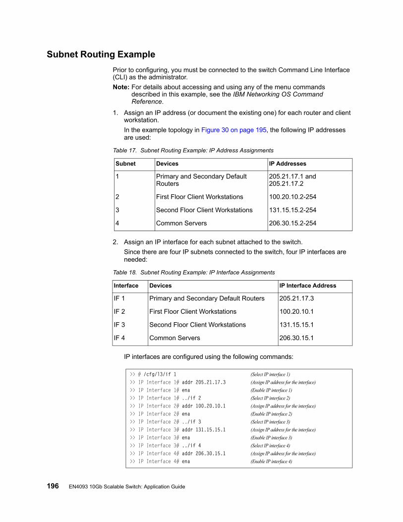
196 EN4093 10Gb Scalable Switch: Application Guide
Subnet Routing Example
Prior to configuring, you must be connected to the switch Command Line Interface (CLI) as the administrator.
Note: For details about accessing and using any of the menu commands described in this example, see the IBM Networking OS Command Reference.
1. Assign an IP address (or document the existing one) for each router and client workstation.
In the example topology in Figure 30 on page 195, the following IP addresses are used:
2. Assign an IP interface for each subnet attached to the switch.
Since there are four IP subnets connected to the switch, four IP interfaces are needed:
IP interfaces are configured using the following commands:
Table 17. Subnet Routing Example: IP Address Assignments
Subnet Devices IP Addresses
1 Primary and Secondary Default Routers
205.21.17.1 and 205.21.17.2
2 First Floor Client Workstations 100.20.10.2-254
3 Second Floor Client Workstations 131.15.15.2-254
4 Common Servers 206.30.15.2-254
Table 18. Subnet Routing Example: IP Interface Assignments
Interface Devices IP Interface Address
IF 1 Primary and Secondary Default Routers 205.21.17.3
IF 2 First Floor Client Workstations 100.20.10.1
IF 3 Second Floor Client Workstations 131.15.15.1
IF 4 Common Servers 206.30.15.1
>> # /cfg/l3/if 1 (Select IP interface 1)
>> IP Interface 1# addr 205.21.17.3 (Assign IP address for the interface)
>> IP Interface 1# ena (Enable IP interface 1)
>> IP Interface 1# ../if 2 (Select IP interface 2)
>> IP Interface 2# addr 100.20.10.1 (Assign IP address for the interface)
>> IP Interface 2# ena (Enable IP interface 2)
>> IP Interface 2# ../if 3 (Select IP interface 3)
>> IP Interface 3# addr 131.15.15.1 (Assign IP address for the interface)
>> IP Interface 3# ena (Enable IP interface 3)
>> IP Interface 3# ../if 4 (Select IP interface 4)
>> IP Interface 4# addr 206.30.15.1 (Assign IP address for the interface)
>> IP Interface 4# ena (Enable IP interface 4)
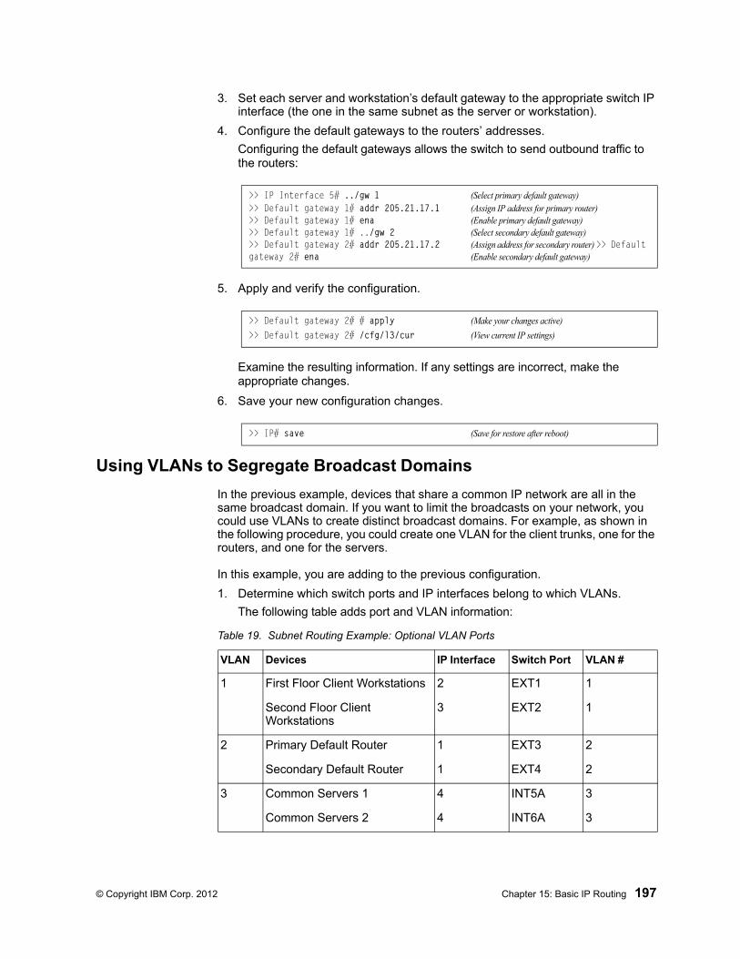
© Copyright IBM Corp. 2012 Chapter 15: Basic IP Routing 197
3. Set each server and workstation’s default gateway to the appropriate switch IP interface (the one in the same subnet as the server or workstation).
4. Configure the default gateways to the routers’ addresses.
Configuring the default gateways allows the switch to send outbound traffic to the routers:
5. Apply and verify the configuration.
Examine the resulting information. If any settings are incorrect, make the appropriate changes.
6. Save your new configuration changes.
Using VLANs to Segregate Broadcast Domains
In the previous example, devices that share a common IP network are all in the same broadcast domain. If you want to limit the broadcasts on your network, you could use VLANs to create distinct broadcast domains. For example, as shown in the following procedure, you could create one VLAN for the client trunks, one for the routers, and one for the servers.
In this example, you are adding to the previous configuration.
1. Determine which switch ports and IP interfaces belong to which VLANs.
The following table adds port and VLAN information:
>> IP Interface 5# ../gw 1 (Select primary default gateway)>> Default gateway 1# addr 205.21.17.1 (Assign IP address for primary router)>> Default gateway 1# ena (Enable primary default gateway)>> Default gateway 1# ../gw 2 (Select secondary default gateway)>> Default gateway 2# addr 205.21.17.2 (Assign address for secondary router) >> Default gateway 2# ena (Enable secondary default gateway)
>> Default gateway 2# # apply (Make your changes active)
>> Default gateway 2# /cfg/l3/cur (View current IP settings)
>> IP# save (Save for restore after reboot)
Table 19. Subnet Routing Example: Optional VLAN Ports
VLAN Devices IP Interface Switch Port VLAN #
1 First Floor Client Workstations 2 EXT1 1
Second Floor Client Workstations
3 EXT2 1
2 Primary Default Router 1 EXT3 2
Secondary Default Router 1 EXT4 2
3 Common Servers 1 4 INT5A 3
Common Servers 2 4 INT6A 3
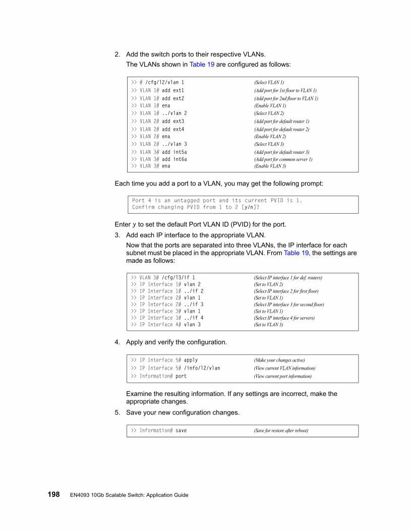
198 EN4093 10Gb Scalable Switch: Application Guide
2. Add the switch ports to their respective VLANs.
The VLANs shown in Table 19 are configured as follows:
Each time you add a port to a VLAN, you may get the following prompt:
Enter y to set the default Port VLAN ID (PVID) for the port.
3. Add each IP interface to the appropriate VLAN.
Now that the ports are separated into three VLANs, the IP interface for each subnet must be placed in the appropriate VLAN. From Table 19, the settings are made as follows:
4. Apply and verify the configuration.
Examine the resulting information. If any settings are incorrect, make the appropriate changes.
5. Save your new configuration changes.
>> # /cfg/l2/vlan 1 (Select VLAN 1)
>> VLAN 1# add ext1 (Add port for 1st floor to VLAN 1)
>> VLAN 1# add ext2 (Add port for 2nd floor to VLAN 1)>> VLAN 1# ena (Enable VLAN 1)
>> VLAN 1# ../vlan 2 (Select VLAN 2)
>> VLAN 2# add ext3 (Add port for default router 1)
>> VLAN 2# add ext4 (Add port for default router 2)>> VLAN 2# ena (Enable VLAN 2)
>> VLAN 2# ../vlan 3 (Select VLAN 3)
>> VLAN 3# add int5a (Add port for default router 3)>> VLAN 3# add int6a (Add port for common server 1)>> VLAN 3# ena (Enable VLAN 3)
Port 4 is an untagged port and its current PVID is 1.Confirm changing PVID from 1 to 2 [y/n]?
>> VLAN 3# /cfg/l3/if 1 (Select IP interface 1 for def. routers)>> IP Interface 1# vlan 2 (Set to VLAN 2)>> IP Interface 1# ../if 2 (Select IP interface 2 for first floor)>> IP Interface 2# vlan 1 (Set to VLAN 1)>> IP Interface 2# ../if 3 (Select IP interface 3 for second floor)>> IP Interface 3# vlan 1 (Set to VLAN 1)>> IP Interface 3# ../if 4 (Select IP interface 4 for servers)>> IP Interface 4# vlan 3 (Set to VLAN 3)
>> IP Interface 5# apply (Make your changes active)
>> IP Interface 5# /info/l2/vlan (View current VLAN information)
>> Information# port (View current port information)
>> Information# save (Save for restore after reboot)

© Copyright IBM Corp. 2012 Chapter 15: Basic IP Routing 199
BOOTP Relay Agent
The EN4093 can function as a Bootstrap Protocol relay agent, enabling the switch to forward a client request for an IP address up to two BOOTP servers with IP addresses that have been configured on the switch.
When a switch receives a BOOTP request from a BOOTP client requesting an IP address, the switch acts as a proxy for the client. The request is then forwarded as a UDP Unicast MAC layer message to two BOOTP servers whose IP addresses are configured on the switch. The servers respond to the switch with a Unicast reply that contains the default gateway and IP address for the client. The switch then forwards this reply back to the client.
Figure 31 shows a basic BOOTP network example.
Figure 31. BOOTP Relay Agent Configuration
The use of two servers provide failover redundancy. The client request is forwarded to both BOOTP servers configured on the switch. However, no health checking is supported.
BOOTP Relay Agent Configuration
To enable the EN4093 to be the BOOTP forwarder, you need to configure the BOOTP server IP addresses on the switch, and enable BOOTP relay on the interface(s) on which the BOOTP requests are received.
Generally, you should configure the command on the switch IP interface that is closest to the client, so that the BOOTP server knows from which IP subnet the newly allocated IP address should come.
Use the following commands to configure the switch as a BOOTP relay agent:
Use the following command to enable the Relay functionality on an IP interface:
BOOT Clientasks for IP from BOOTP server
Blade Switch acts as BOOTP Relay Agent
BOOTP Server
Boston Raleigh
20.1.1.1 10.1.1.2BladeCenter
Blade ChassisBlade Chassis
>> # /cfg/l3/bootp>> Bootstrap Protocol Relay# addr <IP address> (IP address of BOOTP server)>> Bootstrap Protocol Relay# addr2 <IP address> (IP address of 2nd BOOTP server)>> Bootstrap Protocol Relay# on (Globally turn BOOTP relay on)>> Bootstrap Protocol Relay# off (Globally turn BOOTP relay off)>> Bootstrap Protocol Relay# cur (Display current configuration)
>> # /cfg/l3/if <interface number>/relay ena
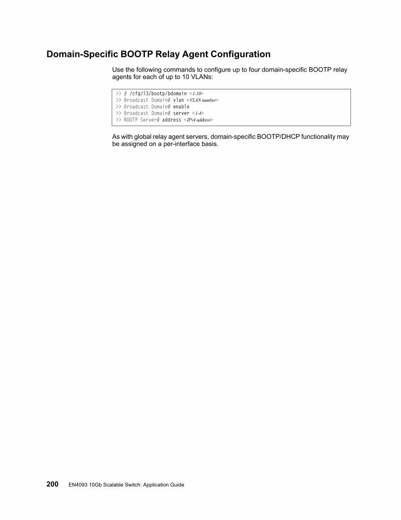
200 EN4093 10Gb Scalable Switch: Application Guide
Domain-Specific BOOTP Relay Agent Configuration
Use the following commands to configure up to four domain-specific BOOTP relay agents for each of up to 10 VLANs:
As with global relay agent servers, domain-specific BOOTP/DHCP functionality may be assigned on a per-interface basis.
>> # /cfg/l3/bootp/bdomain <1-10>>> Broadcast Domain# vlan <VLAN number>>> Broadcast Domain# enable>> Broadcast Domain# server <1-4>>> BOOTP Server# address <IPv4 address>
© Copyright IBM Corp. 2012 Chapter 15: Basic IP Routing 201
Dynamic Host Configuration Protocol
Dynamic Host Configuration Protocol (DHCP) is a transport protocol that provides a framework for automatically assigning IP addresses and configuration information to other IP hosts or clients in a large TCP/IP network. Without DHCP, the IP address must be entered manually for each network device. DHCP allows a network administrator to distribute IP addresses from a central point and automatically send a new IP address when a device is connected to a different place in the network.
DHCP is an extension of another network IP management protocol, Bootstrap Protocol (BOOTP), with an additional capability of being able to dynamically allocate reusable network addresses and configuration parameters for client operation.
Built on the client/server model, DHCP allows hosts or clients on an IP network to obtain their configurations from a DHCP server, thereby reducing network administration. The most significant configuration the client receives from the server is its required IP address; (other optional parameters include the “generic” file name to be booted, the address of the default gateway, and so forth).
DHCP relay agent eliminates the need to have DHCP/BOOTP servers on every subnet. It allows the administrator to reduce the number of DHCP servers deployed on the network and to centralize them. Without the DHCP relay agent, there must be at least one DHCP server deployed at each subnet that has hosts needing to perform the DHCP request.
DHCP Relay Agent
DHCP is described in RFC 2131, and the DHCP relay agent supported on EN4093s is described in RFC 1542. DHCP uses UDP as its transport protocol. The client sends messages to the server on port 67 and the server sends messages to the client on port 68.
DHCP defines the methods through which clients can be assigned an IP address for a finite lease period and allowing reassignment of the IP address to another client later. Additionally, DHCP provides the mechanism for a client to gather other IP configuration parameters it needs to operate in the TCP/IP network.
In the DHCP environment, the EN4093 acts as a relay agent. The DHCP relay feature (/cfg/l3/bootp) enables the switch to forward a client request for an IP address to two BOOTP servers with IP addresses that have been configured on the switch.
When a switch receives a UDP broadcast on port 67 from a DHCP client requesting an IP address, the switch acts as a proxy for the client, replacing the client source IP (SIP) and destination IP (DIP) addresses. The request is then forwarded as a UDP Unicast MAC layer message to two BOOTP servers whose IP addresses are configured on the switch. The servers respond as a UDP Unicast message back to the switch, with the default gateway and IP address for the client. The destination IP address in the server response represents the interface address on the switch that received the client request. This interface address tells the switch on which VLAN to send the server response to the client.
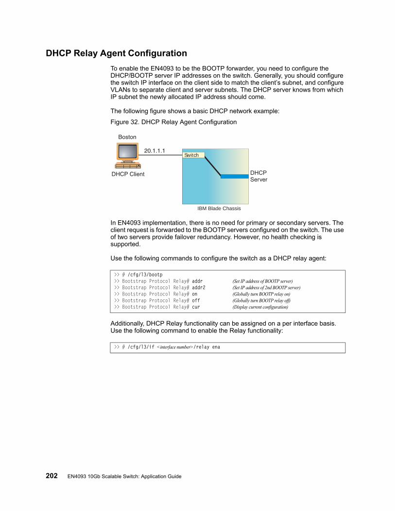
202 EN4093 10Gb Scalable Switch: Application Guide
DHCP Relay Agent Configuration
To enable the EN4093 to be the BOOTP forwarder, you need to configure the DHCP/BOOTP server IP addresses on the switch. Generally, you should configure the switch IP interface on the client side to match the client’s subnet, and configure VLANs to separate client and server subnets. The DHCP server knows from which IP subnet the newly allocated IP address should come.
The following figure shows a basic DHCP network example:
Figure 32. DHCP Relay Agent Configuration
In EN4093 implementation, there is no need for primary or secondary servers. The client request is forwarded to the BOOTP servers configured on the switch. The use of two servers provide failover redundancy. However, no health checking is supported.
Use the following commands to configure the switch as a DHCP relay agent:
Additionally, DHCP Relay functionality can be assigned on a per interface basis. Use the following command to enable the Relay functionality:
IBM Blade Chassis
DHCPServer
Switch
>> # /cfg/l3/bootp>> Bootstrap Protocol Relay# addr (Set IP address of BOOTP server)>> Bootstrap Protocol Relay# addr2 (Set IP address of 2nd BOOTP server)>> Bootstrap Protocol Relay# on (Globally turn BOOTP relay on)>> Bootstrap Protocol Relay# off (Globally turn BOOTP relay off)>> Bootstrap Protocol Relay# cur (Display current configuration)
>> # /cfg/l3/if <interface number>/relay ena
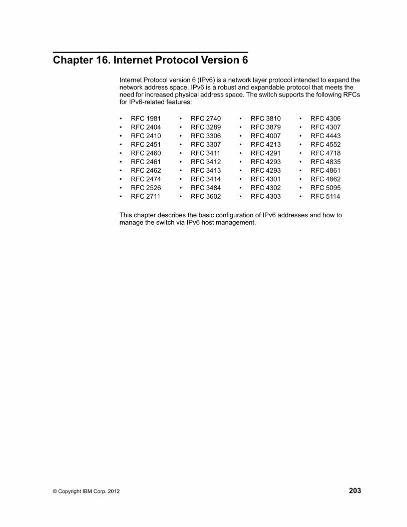
© Copyright IBM Corp. 2012 203
Chapter 16. Internet Protocol Version 6
Internet Protocol version 6 (IPv6) is a network layer protocol intended to expand the network address space. IPv6 is a robust and expandable protocol that meets the need for increased physical address space. The switch supports the following RFCs for IPv6-related features:
This chapter describes the basic configuration of IPv6 addresses and how to manage the switch via IPv6 host management.
• RFC 1981• RFC 2404• RFC 2410• RFC 2451• RFC 2460• RFC 2461• RFC 2462• RFC 2474• RFC 2526• RFC 2711
• RFC 2740• RFC 3289• RFC 3306• RFC 3307• RFC 3411• RFC 3412• RFC 3413• RFC 3414• RFC 3484• RFC 3602
• RFC 3810• RFC 3879• RFC 4007• RFC 4213• RFC 4291• RFC 4293• RFC 4293• RFC 4301• RFC 4302• RFC 4303
• RFC 4306• RFC 4307• RFC 4443• RFC 4552• RFC 4718• RFC 4835• RFC 4861• RFC 4862• RFC 5095• RFC 5114
204 EN4093 10Gb Scalable Switch: Application Guide
IPv6 Limitations
The following IPv6 features are not supported in this release.
• Dynamic Host Control Protocol for IPv6 (DHCPv6)• Border Gateway Protocol for IPv6 (BGP)• Routing Information Protocol for IPv6 (RIPng)
Most other IBM Networking OS 7.2 features permit IP addresses to be configured using either IPv4 or IPv6 address formats. However, the following switch features support IPv4 only:
• Default switch management IP address• Bootstrap Protocol (BOOTP) and DHCP• RADIUS, TACACS+ and LDAP• QoS metering and re-marking ACLs for out-profile traffic• VMware Virtual Center (vCenter) for VMready• Routing Information Protocol (RIP)• Internet Group Management Protocol (IGMP)• Border Gateway Protocol (BGP)• Virtual Router Redundancy Protocol (VRRP)• sFLOW
© Copyright IBM Corp. 2012 Chapter 16: Internet Protocol Version 6 205
IPv6 Address Format
The IPv6 address is 128 bits (16 bytes) long and is represented as a sequence of eight 16-bit hex values, separated by colons.
Each IPv6 address has two parts:
• Subnet prefix representing the network to which the interface is connected
• Local identifier, either derived from the MAC address or user-configured
The preferred hexadecimal format is as follows:
xxxx:xxxx:xxxx:xxxx:xxxx:xxxx:xxxx:xxxx
Example IPv6 address:
FEDC:BA98:7654:BA98:FEDC:1234:ABCD:5412
Some addresses can contain long sequences of zeros. A single contiguous sequence of zeros can be compressed to :: (two colons). For example, consider the following IPv6 address:
FE80:0:0:0:2AA:FF:FA:4CA2
The address can be compressed as follows:
FE80::2AA:FF:FA:4CA2
Unlike IPv4, a subnet mask is not used for IPv6 addresses. IPv6 uses the subnet prefix as the network identifier. The prefix is the part of the address that indicates the bits that have fixed values or are the bits of the subnet prefix. An IPv6 prefix is written in address/prefix-length notation. For example, in the following address, 64 is the network prefix:
21DA:D300:0000:2F3C::/64
IPv6 addresses can be either user-configured or automatically configured. Automatically configured addresses always have a 64-bit subnet prefix and a 64-bit interface identifier. In most implementations, the interface identifier is derived from the switch's MAC address, using a method called EUI-64.
Most IBM Networking OS 7.2 features permit IP addresses to be configured using either IPv4 or IPv6 address formats. Throughout this manual, IP address is used in places where either an IPv4 or IPv6 address is allowed. In places where only one type of address is allowed, the type (IPv4 or IPv6 is specified).
206 EN4093 10Gb Scalable Switch: Application Guide
IPv6 Address Types
IPv6 supports three types of addresses: unicast (one-to-one), multicast (one-to-many), and anycast (one-to-nearest). Multicast addresses replace the use of broadcast addresses.
Unicast Address
Unicast is a communication between a single host and a single receiver. Packets sent to a unicast address are delivered to the interface identified by that address. IPv6 defines the following types of unicast address:
• Global Unicast address: An address that can be reached and identified globally. Global Unicast addresses use the high-order bit range up to FF00, therefore all non-multicast and non-link-local addresses are considered to be global unicast. A manually configured IPv6 address must be fully specified. Autoconfigured IPv6 addresses are comprised of a prefix combined with the 64-bit EUI. RFC 4291 defines the IPv6 addressing architecture.
The interface ID must be unique within the same subnet.
• Link-local unicast address: An address used to communicate with a neighbor on the same link. Link-local addresses use the format FE80::EUI
Link-local addresses are designed to be used for addressing on a single link for purposes such as automatic address configuration, neighbor discovery, or when no routers are present.
Routers must not forward any packets with link-local source or destination addresses to other links.
Multicast
Multicast is communication between a single host and multiple receivers. Packets are sent to all interfaces identified by that address. An interface may belong to any number of multicast groups.
A multicast address (FF00 - FFFF) is an identifier for a group interface. The multicast address most often encountered is a solicited-node multicast address using prefix FF02::1:FF00:0000/104 with the low-order 24 bits of the unicast or anycast address.
The following well-known multicast addresses are pre-defined. The group IDs defined in this section are defined for explicit scope values, as follows:
FF00:::::::0 through FF0F:::::::0
Anycast
Packets sent to an anycast address or list of addresses are delivered to the nearest interface identified by that address. Anycast is a communication between a single sender and a list of addresses.
Anycast addresses are allocated from the unicast address space, using any of the defined unicast address formats. Thus, anycast addresses are syntactically indistinguishable from unicast addresses. When a unicast address is assigned to more than one interface, thus turning it into an anycast address, the nodes to which the address is assigned must be explicitly configured to know that it is an anycast address.
© Copyright IBM Corp. 2012 Chapter 16: Internet Protocol Version 6 207
IPv6 Address Autoconfiguration
IPv6 supports the following types of address autoconfiguration:
• Stateful address configuration
Address configuration is based on the use of a stateful address configuration protocol, such as DHCPv6, to obtain addresses and other configuration options.
• Stateless address configuration
Address configuration is based on the receipt of Router Advertisement messages that contain one or more Prefix Information options.
IBM Networking OS 7.2 supports stateless address configuration.
Stateless address configuration allows hosts on a link to configure themselves with link-local addresses and with addresses derived from prefixes advertised by local routers. Even if no router is present, hosts on the same link can configure themselves with link-local addresses and communicate without manual configuration.
IPv6 Interfaces
Each IPv6 interface supports multiple IPv6 addresses. You can manually configure up to two IPv6 addresses for each interface, or you can allow the switch to use stateless autoconfiguration. By default, the switch automatically configures the IPv6 address of its management interface.
You can manually configure two IPv6 addresses for each interface, as follows:
• Initial IPv6 address is a global unicast or anycast address (/cfg/l3/if <x>/addr).
Note that you cannot configure both addresses as anycast. If you configure an anycast address on the interface you must also configure a global unicast address on that interface.
• Second IPv6 address can be a unicast or anycast address (/cfg/l3/if <x>/secaddr6).
You cannot configure an IPv4 address on an IPv6 management interface. Each interface can be configured with only one address type: either IPv4 or IPv6, but not both. When changing between IPv4 and IPv6 address formats, the prior address settings for the interface are discarded.
Each IPv6 interface can belong to only one VLAN. Each VLAN can support only one IPv6 interface. Each VLAN can support multiple IPv4 interfaces.
Interface 125/126 is reserved for IPv6 host support. This interface is included in management VLAN 4095. Use the IPv6 default gateway menu to configure the IPv6 gateways (/cfg/l3/gw6).
IPv6 gateway 1 is reserved for IPv6 data interfaces. IPv6 gateway 3 and 4 are the default IPv6 management gateways.
208 EN4093 10Gb Scalable Switch: Application Guide
Neighbor Discovery
Neighbor Discovery Overview
The switch uses Neighbor Discovery protocol (ND) to gather information about other router and host nodes, including the IPv6 addresses. Host nodes use ND to configure their interfaces and perform health detection. ND allows each node to determine the link-layer addresses of neighboring nodes, and to keep track of each neighbor’s information. A neighboring node is a host or a router that is linked directly to the switch. The switch supports Neighbor Discovery as described in RFC 4861.
Neighbor Discover messages allow network nodes to exchange information, as follows:
• Neighbor Solicitations allow a node to discover information about other nodes.
• Neighbor Advertisements are sent in response to Neighbor Solicitations. The Neighbor Advertisement contains information required by nodes to determine the link-layer address of the sender, and the sender’s role on the network.
• IPv6 hosts use Router Solicitations to discover IPv6 routers. When a router receives a Router Solicitation, it responds immediately to the host.
• Routers uses Router Advertisements to announce its presence on the network, and to provide its address prefix to neighbor devices. IPv6 hosts listen for Router Advertisements, and uses the information to build a list of default routers. Each host uses this information to perform autoconfiguration of IPv6 addresses.
• Redirect messages are sent by IPv6 routers to inform hosts of a better first-hop address for a specific destination. Redirect messages are only sent by routers for unicast traffic, are only unicast to originating hosts, and are only processed by hosts.
ND configuration for various advertisements, flags, and interval settings is performed on a per-interface basis using the following menu:
Other ND configuration options are available using the following menus:
>> # /cfg/l3/if <interface number>/ip6nd
>> # /cfg/l3/nbrcache (Manage static neighbor cache entries)>> # /cfg/l3/ndprefix (Define prefix profiles for router advertisements
sent from an interface)
© Copyright IBM Corp. 2012 Chapter 16: Internet Protocol Version 6 209
Host vs. Router
Each IPv6 interface can be configured as a router node or a host node, as follows:
• A router node’s IP address is configured manually. Router nodes can send Router Advertisements.
• A host node’s IP address is autoconfigured. Host nodes listen for Router Advertisements that convey information about devices on the network.
Note: When IP forwarding is turned on (/cfg/l3/frwd/on). all IPv6 interfaces configured on the switch can forward packets.
You can configure each IPv6 interface as either a host node or a router node. You can manually assign an IPv6 address to an interface in host mode, or the interface can be assigned an IPv6 address by an upstream router, using information from router advertisements to perform stateless auto-configuration.
To set an interface to host mode, use the following command:
By default, host mode is enabled on the management interface, and disabled on data interfaces.
The EN4093 supports up to 1156 IPv6 routes.
Supported Applications
The following applications have been enhanced to provide IPv6 support.
• Ping
The ping command supports IPv6 addresses. Use the following format to ping an IPv6 address:
ping <host name>|<IPv6 address> [-n <tries (0-4294967295)>] [-w <msec delay (0-4294967295)>] [-l <length (0/32-65500/2080)>] [-s <IP source>] [-v <TOS (0-255)>] [-f] [-t]
To ping a link-local address (begins with FE80), provide an interface index, as follows:
ping <IPv6 address>%<Interface index> [-n <tries (0-4294967295)>] [-w <msec delay (0-4294967295)>] [-l <length (0/32-65500/2080)>] [-s <IP source>] [-v <TOS (0-255)>] [-f] [-t]
• Traceroute
The traceroute command supports IPv6 addresses (but not link-local addresses). Use the following format to perform a traceroute to an IPv6 address:
traceroute <host name>| <IPv6 address> [<max-hops (1-32)> [<msec delay (1-4294967295)>]]
• Telnet server
The telnet command supports IPv6 addresses, but not link-local addresses. Use the following format to Telnet into an IPv6 interface on the switch:
telnet <host name>| <IPv6 address> [<port>]
# /cfg/l3/if <interface number>/ip6host enable
210 EN4093 10Gb Scalable Switch: Application Guide
• Telnet client
The telnet command supports IPv6 addresses, but not link-local addresses. Use the following format to Telnet to an IPv6 address:
telnet <host name>| <IPv6 address> [<port>]
• HTTP/HTTPS
The HTTP/HTTPS servers support both IPv4 and IPv6 connections.
• SSH
Secure Shell (SSH) connections over IPv6 are supported, but not link-local addresses. The following syntax is required from the client:
ssh -u <IPv6 address>
Example:
ssh -u 2001:2:3:4:0:0:0:142
• TFTP
The TFTP commands support both IPv4 and IPv6 addresses. Link-local addresses are not supported.
• FTP
The FTP commands support both IPv4 and IPv6 addresses. Link-local addresses are not supported.
• DNS client
DNS commands support both IPv4 and IPv6 addresses. Link-local addresses are not supported. Use the following command to specify the type of DNS query to be sent first:
If you set the request version to v4, the DNS application sends an A query first, to resolve the hostname with an IPv4 address. If no A record is found for that hostname (no IPv4 address for that hostname) an AAAA query is sent to resolve the hostname with a IPv6 address.
If you set the request version to v6, the DNS application sends an AAAA query first, to resolve the hostname with an IPv6 address. If no AAAA record is found for that hostname (no IPv6 address for that hostname) an A query is sent to resolve the hostname with an IPv4 address.
# /cfg/l3/dns/reqver v4|v6
© Copyright IBM Corp. 2012 Chapter 16: Internet Protocol Version 6 211
Configuration Guidelines
When you configure an interface for IPv6, consider the following guidelines:
• Support for subnet router anycast addresses is not available.
• Interface 125/126 are reserved for IPv6 management.
• A single interface can accept either IPv4 or IPv6 addresses, but not both IPv4 and IPv6 addresses.
• A single interface can accept multiple IPv6 addresses.
• A single interface can accept only one IPv4 address.
• If you change the IPv6 address of a configured interface to an IPv4 address, all IPv6 settings are deleted.
• A single VLAN can support only one IPv6 interface.
• Health checks are not supported for IPv6 gateways.
• IPv6 interfaces support Path MTU Discovery. The CPU’s MTU is fixed at 1500 bytes.
• Support for jumbo frames (1,500 to 9,216 byte MTUs) is limited. Any jumbo frames intended for the CPU must be fragmented by the remote node. The switch can re-assemble fragmented packets up to 9k. It can also fragment and transmit jumbo packets received from higher layers.
IPv6 Configuration Examples
This section provides steps to configure IPv6 on the switch.
IPv6 Example 1
The following example uses IPv6 host mode to autoconfigure an IPv6 address for the interface. By default, the interface is assigned to VLAN 1.
1. Enable IPv6 host mode on an interface.
2. Configure the IPv6 default gateway.
3. Verify the interface address.
>> # /cfg/l3/if 2 (Select IP interface 2)
>> IP Interface 2# ip6host enable (Enable IPv6 host mode
>> IP Interface 2# ena (Enable the IP interface)
>> # /cfg/l3/gw6 1 (Select IPv6 default gateway)>> Default gateway 1# addr 2001:BA98:7654:BA98:FEDC:1234:ABCD:5412>> Default gateway 1# ena (Enable default gateway)
>> # /info/l3/if 2 (Display interface information)
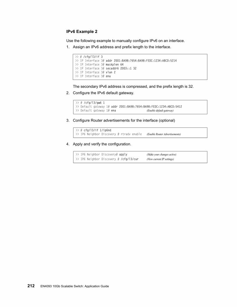
212 EN4093 10Gb Scalable Switch: Application Guide
IPv6 Example 2
Use the following example to manually configure IPv6 on an interface.
1. Assign an IPv6 address and prefix length to the interface.
The secondary IPv6 address is compressed, and the prefix length is 32.
2. Configure the IPv6 default gateway.
3. Configure Router advertisements for the interface (optional)
4. Apply and verify the configuration.
>> # /cfg/l3/if 3>> IP Interface 3# addr 2001:BA98:7654:BA98:FEDC:1234:ABCD:5214>> IP Interface 3# maskplen 64>> IP Interface 3# secaddr6 2003::1 32>> IP Interface 3# vlan 2>> IP Interface 3# ena
>> # /cfg/l3/gw6 1>> Default gateway 1# addr 2001:BA98:7654:BA98:FEDC:1234:ABCD:5412>> Default gateway 1# ena (Enable default gateway)
>> # cfg/l3/if 1/ip6nd>> IP6 Neighbor Discovery # rtradv enable (Enable Router Advertisements)
>> IP6 Neighbor Discovery# apply (Make your changes active)
>> IP6 Neighbor Discovery # /cfg/l3/cur (View current IP settings)
© Copyright IBM Corp. 2012 213
Chapter 17. Using IPsec with IPv6
Internet Protocol Security (IPsec) is a protocol suite for securing Internet Protocol (IP) communications by authenticating and encrypting each IP packet of a communication session. IPsec also includes protocols for establishing mutual authentication between agents at the beginning of the session and negotiation of cryptographic keys to be used during the session.
Since IPsec was implemented in conjunction with IPv6, all implementations of IPv6 must contain IPsec. To support the National Institute of Standards and Technology (NIST) recommendations for IPv6 implementations, IBM Networking OS IPv6 feature compliance has been extended to include the following IETF RFCs, with an emphasis on IP Security (IPsec) and Internet Key Exchange version 2, and authentication/confidentiality for OSPFv3:
• RFC 4301 for IPv6 security• RFC 4302 for the IPv6 Authentication Header• RFCs 2404, 2410, 2451, 3602, and 4303 for IPv6 Encapsulating Security Pay-
load (ESP), including NULL encryption, CBC-mode 3DES and AES ciphers, and HMAC-SHA-1-96.
• RFCs 4306, 4307, 4718, and 4835 for IKEv2 and cryptography• RFC 4552 for OSPFv3 IPv6 authentication• RFC 5114 for Diffie-Hellman groups
Note: This implementation of IPsec supports DH groups 1, 2, 5, 14, and 24.
The following topics are discussed in this chapter:
• “IPsec Protocols” on page 214
• “Using IPsec with the EN4093” on page 215
214 IBM Flex System Fabric EN4093 10Gb Scalable Switch: Application Guide
IPsec ProtocolsThe IBM Networking OS implementation of IPsec supports the following protocols:
• Authentication Header (AH)
AHs provide connectionless integrity outand data origin authentication for IP packets, and provide protection against replay attacks. In IPv6, the AH protects the AH itself, the Destination Options extension header after the AH, and the IP payload. It also protects the fixed IPv6 header and all extension headers before the AH, except for the mutable fields DSCP, ECN, Flow Label, and Hop Limit. AH is defined in RFC 4302.
• Encapsulating Security Payload (ESP)
ESPs provide confidentiality, data origin authentication, integrity, an anti-replay service (a form of partial sequence integrity), and some traffic flow confidentiality. ESPs may be applied alone or in combination with an AH. ESP is defined in RFC 4303.
• Internet Key Exchange Version 2 (IKEv2)
IKEv2 is used for mutual authentication between two network elements. An IKE establishes a security association (SA) that includes shared secret information to efficiently establish SAs for ESPs and AHs, and a set of cryptographic algorithms to be used by the SAs to protect the associated traffic. IKEv2 is defined in RFC 4306.
Using IKEv2 as the foundation, IPsec supports ESP for encryption and/or authentication, and/or AH for authentication of the remote partner.
Both ESP and AH rely on security associations. A security association (SA) is the bundle of algorithms and parameters (such as keys) that encrypt and authenticate a particular flow in one direction.

© Copyright IBM Corp. 2012 Chapter 17: Using IPsec with IPv6 215
Using IPsec with the EN4093IPsec supports the fragmentation and reassembly of IP packets that occurs when data goes to and comes from an external device. The IBM Flex System Fabric EN4093 10Gb Scalable Switch acts as an end node that processes any fragmentation and reassembly of packets but does not forward the IPsec traffic. The IKEv2 key must be authenticated before you can use IPsec.
The security protocol for the session key is either ESP or AH. Outgoing packets are labeled with the SA SPI (Security Parameter Index), which the remote device will use in its verification and decryption process.
Every outgoing IPv6 packet is checked against the IPsec policies in force. For each outbound packet, after the packet is encrypted, the software compares the packet size with the MTU size that it either obtains from the default minimum maximum transmission unit (MTU) size (1500) or from path MTU discovery. If the packet size is larger than the MTU size, the receiver drops the packet and sends a message containing the MTU size to the sender. The sender then fragments the packet into smaller pieces and retransmits them using the correct MTU size.
The maximum traffic load for each IPSec packet is limited to the following:
• IKEv2 SAs: 5
• IPsec SAs: 10 (5 SAs in each direction)
• SPDs: 20 (10 policies in each direction)
IPsec is implemented as a software cryptography engine designed for handling control traffic, such as network management. IPsec is not designed for handling data traffic, such as a VPN.

216 IBM Flex System Fabric EN4093 10Gb Scalable Switch: Application Guide
Setting up AuthenticationBefore you can use IPsec, you need to have key policy authentication in place. There are two types of key policy authentication:
• Preshared key (default)
The parties agree on a shared, secret key that is used for authentication in an IPsec policy. During security negotiation, information is encrypted before transmission by using a session key created by using a Diffie-Hellman calculation and the shared, secret key. Information is decrypted on the receiving end using the same key. One IPsec peer authenticates the other peer's packet by decryption and verification of the hash inside the packet (the hash inside the packet is a hash of the preshared key). If authentication fails, the packet is discarded.
• Digital certificate (using RSA algorithms)
The peer being validated must hold a digital certificate signed by a trusted Certificate Authority and the private key for that digital certificate. The side performing the authentication only needs a copy of the trusted certificate authorities digital certificate. During IKEv2 authentication, the side being validated sends a copy of the digital certificate and a hash value signed using the private key. The certificate can be either generated or imported.
Note: During the IKEv2 negotiation phase, the digital certificate takes precedence over the preshared key.
Creating an IKEv2 ProposalWith IKEv2, a single policy can have multiple encryption and authentication types, as well as multiple integrity algorithms.
To create an IKEv2 proposal:
1. Enter IKEv2 proposal mode.
2. Set the DES encryption algorithm.
3. Set the authentication integrity algorithm type.
4. Set the Diffie-Hellman group.
>> /cfg/l3/ikev2/prop
>> IKEv2 Proposal# cipher des|3des|aes (default: 3des)
>> IKEv2 Proposal# auth sha1|md5|none (default: sha1)
>> IKEv2 Proposal# group 1|2|5|14|24 (default: 2)
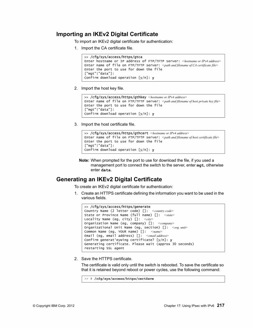
© Copyright IBM Corp. 2012 Chapter 17: Using IPsec with IPv6 217
Importing an IKEv2 Digital CertificateTo import an IKEv2 digital certificate for authentication:
1. Import the CA certificate file.
2. Import the host key file.
3. Import the host certificate file.
Note: When prompted for the port to use for download the file, if you used a management port to connect the switch to the server, enter mgt, otherwise enter data.
Generating an IKEv2 Digital CertificateTo create an IKEv2 digital certificate for authentication:
1. Create an HTTPS certificate defining the information you want to be used in the various fields.
2. Save the HTTPS certificate.
The certificate is valid only until the switch is rebooted. To save the certificate so that it is retained beyond reboot or power cycles, use the following command:
>> /cfg/sys/access/https/gtca
Enter hostname or IP address of FTP/TFTP server: <hostname or IPv4 address>Enter name of file on FTP/TFTP server: <path and filename of CA certificate file>Enter the port to use for down the file
["mgt"|"data"]:Confirm download operation [y/n]: y
>> /cfg/sys/access/https/gthkey <hostname or IPv4 address>Enter name of file on FTP/TFTP server: <path and filename of host private key file>Enter the port to use for down the file
["mgt"|"data"]:Confirm download operation [y/n]: y
>> /cfg/sys/access/https/gthcert <hostname or IPv4 address>Enter name of file on FTP/TFTP server: <path and filename of host certificate file>Enter the port to use for down the file
["mgt"|"data"]:Confirm download operation [y/n]: y
>> /cfg/sys/access/https/generate
Country Name (2 letter code) []: <country code>State or Province Name (full name) []: <state>Locality Name (eg, city) []: <city>Organization Name (eg, company) []: <company>Organizational Unit Name (eg, section) []: <org. unit>Common Name (eg, YOUR name) []: <name>Email (eg, email address) []: <email address>Confirm generat‘eywing certificate? [y/n]: yGenerating certificate. Please wait (approx 30 seconds)
restarting SSL agent
>> # /cfg/sys/access/https/certSave
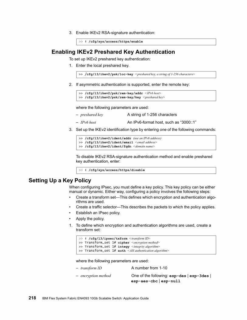
218 IBM Flex System Fabric EN4093 10Gb Scalable Switch: Application Guide
3. Enable IKEv2 RSA-signature authentication:
Enabling IKEv2 Preshared Key AuthenticationTo set up IKEv2 preshared key authentication:
1. Enter the local preshared key.
2. If asymmetric authentication is supported, enter the remote key:
where the following parameters are used:
– preshared key A string of 1-256 characters
– IPv6 host An IPv6-format host, such as “3000::1”
3. Set up the IKEv2 identification type by entering one of the following commands:
To disable IKEv2 RSA-signature authentication method and enable preshared key authentication, enter:
Setting Up a Key PolicyWhen configuring IPsec, you must define a key policy. This key policy can be either manual or dynamic. Either way, configuring a policy involves the following steps:
• Create a transform set—This defines which encryption and authentication algo-rithms are used.
• Create a traffic selector—This describes the packets to which the policy applies.
• Establish an IPsec policy.
• Apply the policy.
1. To define which encryption and authentication algorithms are used, create a transform set:
where the following parameters are used:
– transform ID A number from 1-10
– encryption method One of the following: esp-des | esp-3des | esp-aes-cbc | esp-null
>> # /cfg/sys/access/https/enable
>> /cfg/l3/ikev2/psk/loc-key <preshared key, a string of 1-256 characters>
>> /cfg/l3/ikev2/psk/rem-key/addr <IPv6 host>>> /cfg/l3/ikev2/psk/rem-key/key <preshared key>
>> /cfg/l3/ikev2/ident/addr (use an IPv6 address)>> /cfg/l3/ikev2/ident/email <email address>>> /cfg/l3/ikev2/ident/fqdn <domain name>
>> # /cfg/sys/access/https/disable
>> # /cfg/l3/ipsec/txform <transform ID>>> Transform_set 1# cipher <encryption method>>> Transform_set 1# integy <integrity algorithm>>> Transform_set 1# auth <AH authentication algorithm>

© Copyright IBM Corp. 2012 Chapter 17: Using IPsec with IPv6 219
– integrity algorithm One of the following: esp-sha1 | esp-md5 | none
– AH authentication algorithm One of the following: ah-sha1 | ah-md5 | none
2. Decide whether to use tunnel or transport mode. The default mode is transport.
3. To describe the packets to which this policy applies, create a traffic selector using the following commands:
where the following parameters are used:
– traffic selector number an integer from 1-10
– permit|deny whether or not to permit IPsec encryption of traffic that meets the criteria specified in this command
– proto/any apply the selector to any type of traffic
– proto/icmp type|any only apply the selector only to ICMP traffic of the specified type (an integer from 1-255) or to any ICMP traffic
– proto/tcp only apply the selector to TCP traffic
– source IP address|any the source IP address in IPv6 format or “any” source
– destination IP address|any the destination IP address in IPv6 format or “any” destination
– prefix length (Optional) the length of the destination IPv6 prefix; an integer from 1-128
Permitted traffic that matches the policy in force is encrypted, while denied traffic that matches the policy in force is dropped. Traffic that does not match the policy bypasses IPsec and passes through clear (unencrypted).
4. Choose whether to use a manual or a dynamic policy.
>> Transform_set 1# mode tunnel|txport
>> # /cfg/l3/ipsec/selector <traffic selector number>
>> Traffic_selector 1# permit|deny (permit or deny traffic)
>> Traffic_selector 1# proto/icmp <type>|tcp|any(protocol traffic selector)>> Traffic_selector 1# src <IPv6 address of the source>>> Traffic_selector 1# prefix <prefix length>>> Traffic_selector 1# dst <IPv6 destination address>
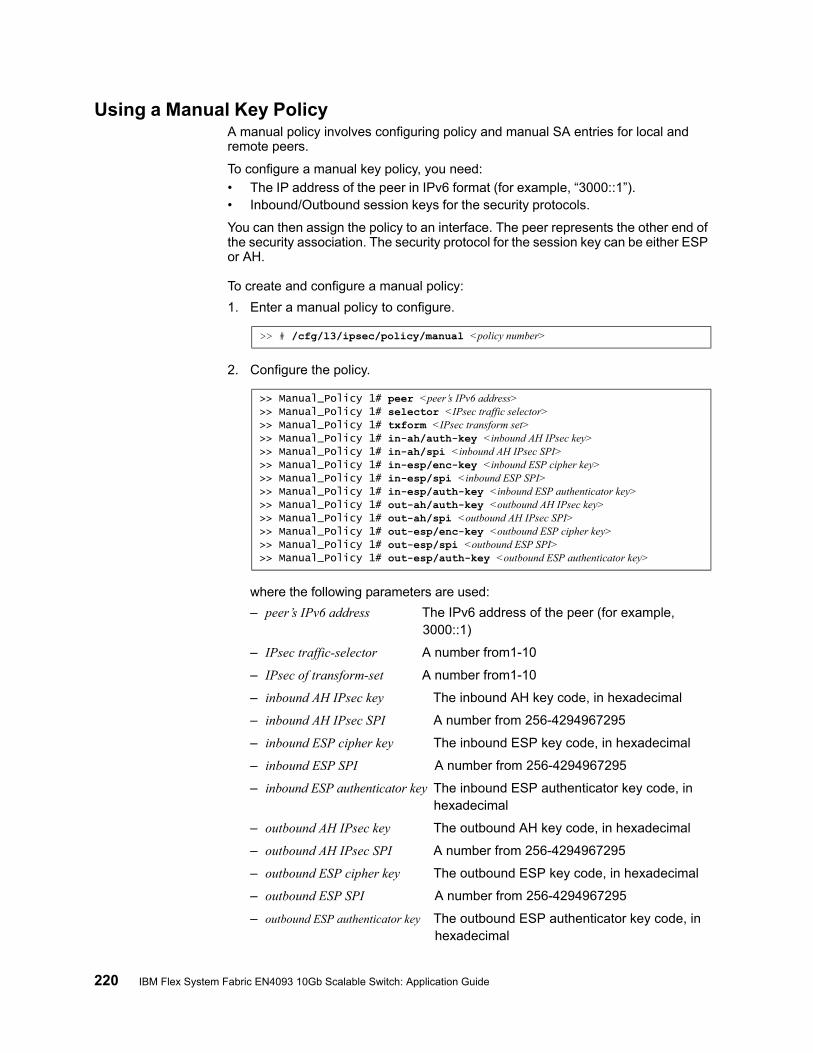
220 IBM Flex System Fabric EN4093 10Gb Scalable Switch: Application Guide
Using a Manual Key PolicyA manual policy involves configuring policy and manual SA entries for local and remote peers.
To configure a manual key policy, you need:
• The IP address of the peer in IPv6 format (for example, “3000::1”).• Inbound/Outbound session keys for the security protocols.
You can then assign the policy to an interface. The peer represents the other end of the security association. The security protocol for the session key can be either ESP or AH.
To create and configure a manual policy:
1. Enter a manual policy to configure.
2. Configure the policy.
where the following parameters are used:
– peer’s IPv6 address The IPv6 address of the peer (for example, 3000::1)
– IPsec traffic-selector A number from1-10
– IPsec of transform-set A number from1-10
– inbound AH IPsec key The inbound AH key code, in hexadecimal
– inbound AH IPsec SPI A number from 256-4294967295
– inbound ESP cipher key The inbound ESP key code, in hexadecimal
– inbound ESP SPI A number from 256-4294967295
– inbound ESP authenticator key The inbound ESP authenticator key code, in hexadecimal
– outbound AH IPsec key The outbound AH key code, in hexadecimal
– outbound AH IPsec SPI A number from 256-4294967295
– outbound ESP cipher key The outbound ESP key code, in hexadecimal
– outbound ESP SPI A number from 256-4294967295
– outbound ESP authenticator key The outbound ESP authenticator key code, in hexadecimal
>> # /cfg/l3/ipsec/policy/manual <policy number>
>> Manual_Policy 1# peer <peer’s IPv6 address>>> Manual_Policy 1# selector <IPsec traffic selector>>> Manual_Policy 1# txform <IPsec transform set>>> Manual_Policy 1# in-ah/auth-key <inbound AH IPsec key>>> Manual_Policy 1# in-ah/spi <inbound AH IPsec SPI>>> Manual_Policy 1# in-esp/enc-key <inbound ESP cipher key>>> Manual_Policy 1# in-esp/spi <inbound ESP SPI>>> Manual_Policy 1# in-esp/auth-key <inbound ESP authenticator key>>> Manual_Policy 1# out-ah/auth-key <outbound AH IPsec key>>> Manual_Policy 1# out-ah/spi <outbound AH IPsec SPI>>> Manual_Policy 1# out-esp/enc-key <outbound ESP cipher key>>> Manual_Policy 1# out-esp/spi <outbound ESP SPI>>> Manual_Policy 1# out-esp/auth-key <outbound ESP authenticator key>

© Copyright IBM Corp. 2012 Chapter 17: Using IPsec with IPv6 221
Note: When configuring a manual policy ESP, the ESP authenticator key is optional.
3. After you configure the IPSec policy, you need to apply it to the interface to enforce the security policies on that interface and save it to keep it in place after a reboot. To accomplish this, enter:
>> Main# apply>> Main# save
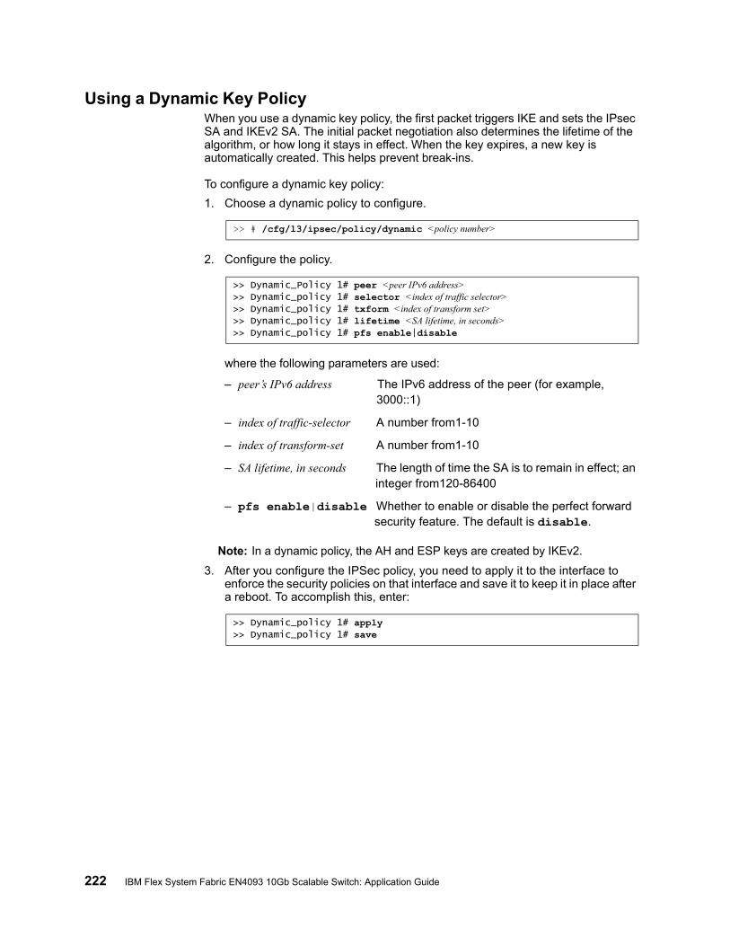
222 IBM Flex System Fabric EN4093 10Gb Scalable Switch: Application Guide
Using a Dynamic Key PolicyWhen you use a dynamic key policy, the first packet triggers IKE and sets the IPsec SA and IKEv2 SA. The initial packet negotiation also determines the lifetime of the algorithm, or how long it stays in effect. When the key expires, a new key is automatically created. This helps prevent break-ins.
To configure a dynamic key policy:
1. Choose a dynamic policy to configure.
2. Configure the policy.
where the following parameters are used:
– peer’s IPv6 address The IPv6 address of the peer (for example, 3000::1)
– index of traffic-selector A number from1-10
– index of transform-set A number from1-10
– SA lifetime, in seconds The length of time the SA is to remain in effect; an integer from120-86400
– pfs enable|disable Whether to enable or disable the perfect forward security feature. The default is disable.
Note: In a dynamic policy, the AH and ESP keys are created by IKEv2.
3. After you configure the IPSec policy, you need to apply it to the interface to enforce the security policies on that interface and save it to keep it in place after a reboot. To accomplish this, enter:
>> # /cfg/l3/ipsec/policy/dynamic <policy number>
>> Dynamic_Policy 1# peer <peer IPv6 address>>> Dynamic_policy 1# selector <index of traffic selector>>> Dynamic_policy 1# txform <index of transform set>>> Dynamic_policy 1# lifetime <SA lifetime, in seconds>>> Dynamic_policy 1# pfs enable|disable
>> Dynamic_policy 1# apply>> Dynamic_policy 1# save
© Copyright IBM Corp. 2012 223
Chapter 18. Routing Information Protocol
In a routed environment, routers communicate with one another to keep track of available routes. Routers can learn about available routes dynamically using the Routing Information Protocol (RIP). IBM Networking OS software supports RIP version 1 (RIPv1) and RIP version 2 (RIPv2) for exchanging TCP/IPv4 route information with other routers.
Note: IBM Networking OS 7.2 does not support IPv6 for RIP.
Distance Vector Protocol
RIP is known as a distance vector protocol. The vector is the network number and next hop, and the distance is the cost associated with the network number. RIP identifies network reachability based on metric, and metric is defined as hop count. One hop is considered to be the distance from one switch to the next, which typically is 1.
When a switch receives a routing update that contains a new or changed destination network entry, the switch adds 1 to the metric value indicated in the update and enters the network in the routing table. The IPv4 address of the sender is used as the next hop.
Stability
RIP includes a number of other stability features that are common to many routing protocols. For example, RIP implements the split horizon and hold-down mechanisms to prevent incorrect routing information from being propagated.
RIP prevents routing loops from continuing indefinitely by limiting the number of hops allowed in a path from the source to a destination. The maximum number of hops in a path is 15. The network destination network is considered unreachable if increasing the metric value by 1 causes the metric to be 16 (that is infinity). This limits the maximum diameter of a RIP network to less than 16 hops.
RIP is often used in stub networks and in small autonomous systems that do not have many redundant paths.
224 EN4093 10Gb Scalable Switch: Application Guide
Routing Updates
RIP sends routing-update messages at regular intervals and when the network topology changes. Each router “advertises” routing information by sending a routing information update every 30 seconds. If a router doesn’t receive an update from another router for 180 seconds, those routes provided by that router are declared invalid. The routes are removed from the routing table, but they remain in the RIP routes table (/info/l3/rip/routes). After another 120 seconds without receiving an update for those routes, the routes are removed from regular updates.
When a router receives a routing update that includes changes to an entry, it updates its routing table to reflect the new route. The metric value for the path is increased by 1, and the sender is indicated as the next hop. RIP routers maintain only the best route (the route with the lowest metric value) to a destination.
For more information see The Configuration Menu, Routing Information Protocol Configuration (/cfg/l3/rip) in the IBM Networking OS Command Reference.
RIPv1
RIP version 1 uses broadcast User Datagram Protocol (UDP) data packets for the regular routing updates. The main disadvantage is that the routing updates do not carry subnet mask information. Hence, the router cannot determine whether the route is a subnet route or a host route. It is of limited usage after the introduction of RIPv2. For more information about RIPv1 and RIPv2, refer to RFC 1058 and RFC 2453.
RIPv2
RIPv2 is the most popular and preferred configuration for most networks. RIPv2 expands the amount of useful information carried in RIP messages and provides a measure of security. For a detailed explanation of RIPv2, refer to RFC 1723 and RFC 2453.
RIPv2 improves efficiency by using multicast UDP (address 224.0.0.9) data packets for regular routing updates. Subnet mask information is provided in the routing updates. A security option is added for authenticating routing updates, by using a shared password. IBM Networking OS supports using clear password for RIPv2.
RIPv2 in RIPv1 Compatibility Mode
IBM Networking OS allows you to configure RIPv2 in RIPv1compatibility mode, for using both RIPv2 and RIPv1 routers within a network. In this mode, the regular routing updates use broadcast UDP data packet to allow RIPv1 routers to receive those packets. With RIPv1 routers as recipients, the routing updates have to carry natural or host mask. Hence, it is not a recommended configuration for most network topologies.
Note: When using both RIPv1 and RIPv2 within a network, use a single subnet mask throughout the network.
© Copyright IBM Corp. 2012 Chapter 18: Routing Information Protocol 225
RIP Features
IBM Networking OS provides the following features to support RIPv1 and RIPv2:
Poison Reverse
Simple split horizon in RIP omits routes learned from one neighbor in updates sent to that neighbor. That is the most common configuration used in RIP, with the Poison Reverse feature disabled. Split horizon with poisoned reverse enabled includes such routes in updates, but sets their metrics to 16. The disadvantage of using this feature is the increase of size in the routing updates.
Triggered Updates
Triggered updates are an attempt to speed up convergence. When Triggered Updates is enabled (/cfg/l3/rip/if <x>/trigg/e), whenever a router changes the metric for a route, it sends update messages almost immediately, without waiting for the regular update interval. It is recommended to enable Triggered Updates.
Multicast
RIPv2 messages use IPv4 multicast address (224.0.0.9) for periodic updates. Multicast RIPv2 updates are not processed by RIPv1 routers. IGMP is not needed since these are inter-router messages which are not forwarded.
To configure RIPv2 in RIPv1 compatibility mode, set multicast to disable, and set version to both.
Default Route
The RIP router can listen and supply a default route, usually represented as IPv4 0.0.0.0 in the routing table. When a router does not have an explicit route to a destination network in its routing table, it uses the default route to forward those packets.
Metric
The metric field contains a configurable value between 1 and 15 (inclusive) which specifies the current metric for the interface. The metric value typically indicates the total number of hops to the destination. The metric value of 16 represents an unreachable destination.
Authentication
RIPv2 authentication uses plain text password for authentication. If configured using Authentication password, then it is necessary to enter an authentication key value.
The following method is used to authenticate a RIP message:
• If the router is not configured to authenticate RIPv2 messages, then RIPv1 and unauthenticated RIPv2 messages are accepted; authenticated RIPv2 messages are discarded.
226 EN4093 10Gb Scalable Switch: Application Guide
• If the router is configured to authenticate RIPv2 messages, then RIPv1 and RIPv2 messages which pass authentication testing are accepted; unauthenticated and failed authentication RIPv2 messages are discarded.
For maximum security, RIPv1 messages are ignored when authentication is enabled (/cfg/l3/rip/if <x>/auth/password); otherwise, the routing information from authenticated messages is propagated by RIPv1 routers in an unauthenticated manner.
RIP Configuration ExampleNote: An interface RIP disabled uses all the default values of the RIP, no matter
how the RIP parameters are configured for that interface. RIP sends out RIP regular updates to include an UP interface, but not a DOWN interface.
1. Add VLANs for routing interfaces.
2. Add IP interfaces with IPv4 addresses to VLANs.
3. Turn on RIP globally and enable RIP for each interface.
Use the following command to check the current valid routes in the routing table of the switch: /maint/route/dump
For those RIP learnt routes within the garbage collection period, that are routes phasing out of the routing table with metric 16, use the following command: /info/l3/rip/routes Locally configured static routes do not appear in the RIP Routes table.
>> Main# /cfg/l2/vlan 2/ena (Enable VLAN 2)>> VLAN 2# add ext2 (Add port EXT2 to VLAN 2)Port EXT2 is an UNTAGGED port and its current PVID is 1.Confirm changing PVID from 1 to 2 [y/n]: y>> VLAN 2# /cfg/l2/vlan 3/ena (Enable VLAN 3)>> VLAN 3# add ext3 (Add port EXT3 to VLAN 3)Port EXT3 is an UNTAGGED port and its current PVID is 1.Confirm changing PVID from 1 to 3 [y/n]: y
>> VLAN 3# /cfg/l3/if 2/ena (Enable interface 2)>> IP Interface 2# addr 102.1.1.1 (Define IPv4 address for interface 2)>> IP Interface 2# vlan 2 (Add interface 2 to VLAN 2)>> IP Interface 2# /cfg/l3/if 3/ena (Enable interface 3)>> IP Interface 3# addr 103.1.1.1 (Define IPv4 address for interface 3)>> IP Interface 3# vlan 3 (Add interface 3 to VLAN 3)
>> IP Interface 3# /cfg/l3/rip/on (Turn on RIP globally)>> Routing Information Protocol# if 2/ena (Enable RIP on IP interface 2)>> RIP Interface 2# ..>> Routing Information Protocol# if 3/ena (Enable RIP on IP interface 3)>> RIP Interface 3# apply (Apply your changes)>> RIP Interface 3# save (Save the configuration)
© Copyright IBM Corp. 2012 227
Chapter 19. Internet Group Management Protocol
Internet Group Management Protocol (IGMP) is used by IPv4 Multicast routers to learn about the existence of host group members on their directly attached subnet (see RFC 2236). The IPv4 Multicast routers get this information by broadcasting IGMP Membership Queries and listening for IPv4 hosts reporting their host group memberships. This process is used to set up a client/server relationship between an IPv4 Multicast source that provides the data streams and the clients that want to receive the data.
The EN4093 10Gb Scalable Switch (EN4093) can perform IGMP Snooping, or act as an IGMP Relay (proxy) device.
Note: IBM Networking OS 7.2 does not support IPv6 for IGMP.
The following topics are discussed in this chapter:
• “IGMP Snooping” on page 228
• “IGMP Querier” on page 234
• “Additional IGMP Features” on page 235

228 EN4093 10Gb Scalable Switch: Application Guide
IGMP Snooping
IGMP Snooping allows the switch to forward multicast traffic only to those ports that request it. IGMP Snooping prevents multicast traffic from being flooded to all ports. The switch learns which server hosts are interested in receiving multicast traffic, and forwards it only to ports connected to those servers.
IGMP Snooping conserves bandwidth. With IGMP Snooping, the switch learns which ports are interested in receiving multicast data, and forwards multicast data only to those ports. In this way, other ports are not burdened with unwanted multicast traffic.
The switch can sense IGMP Membership Reports from attached clients and act as a proxy to set up a dedicated path between the requesting host and a local IPv4 Multicast router. After the pathway is established, the switch blocks the IPv4 Multicast stream from flowing through any port that does not connect to a host member, thus conserving bandwidth.
The client-server path is set up as follows:
• An IPv4 Multicast Router (Mrouter) sends Membership Queries to the switch, which forwards them to all ports in a given VLAN.
• Hosts that want to receive the multicast data stream send Membership Reports to the switch, which sends a proxy Membership Report to the Mrouter.
• The switch sets up a path between the Mrouter and the host, and blocks all other ports from receiving the multicast.
• Periodically, the Mrouter sends Membership Queries to ensure that the host wants to continue receiving the multicast. If a host fails to respond with a Membership Report, the Mrouter stops sending the multicast to that path.
• The host can send an IGMP Leave packet to the switch, which responds with an IGMP Groups Specific Query in order to check if there are other clients that want to receive the multicast traffic for the group referenced in the Leave packet. If an IGMP Report is not received, the group is deleted from the port and the multicast path is terminated. The switch then sends a Proxy Leave packet to the Mrouter in order to updated it. If the FastLeave option is enabled on a VLAN, the multicast path is terminated immediately and the Leave packet is directly forwarded to the Mrouter.
IGMP Groups
The EN4093 supports a maximum of 3072 IGMP entries, on a maximum of 1023 VLANs. One IGMP entry is allocated for each unique join request, based on the VLAN and IGMP group address only (regardless of the port). If multiple ports join the same IGMP group using the same VLAN, only a single IGMP entry is used.
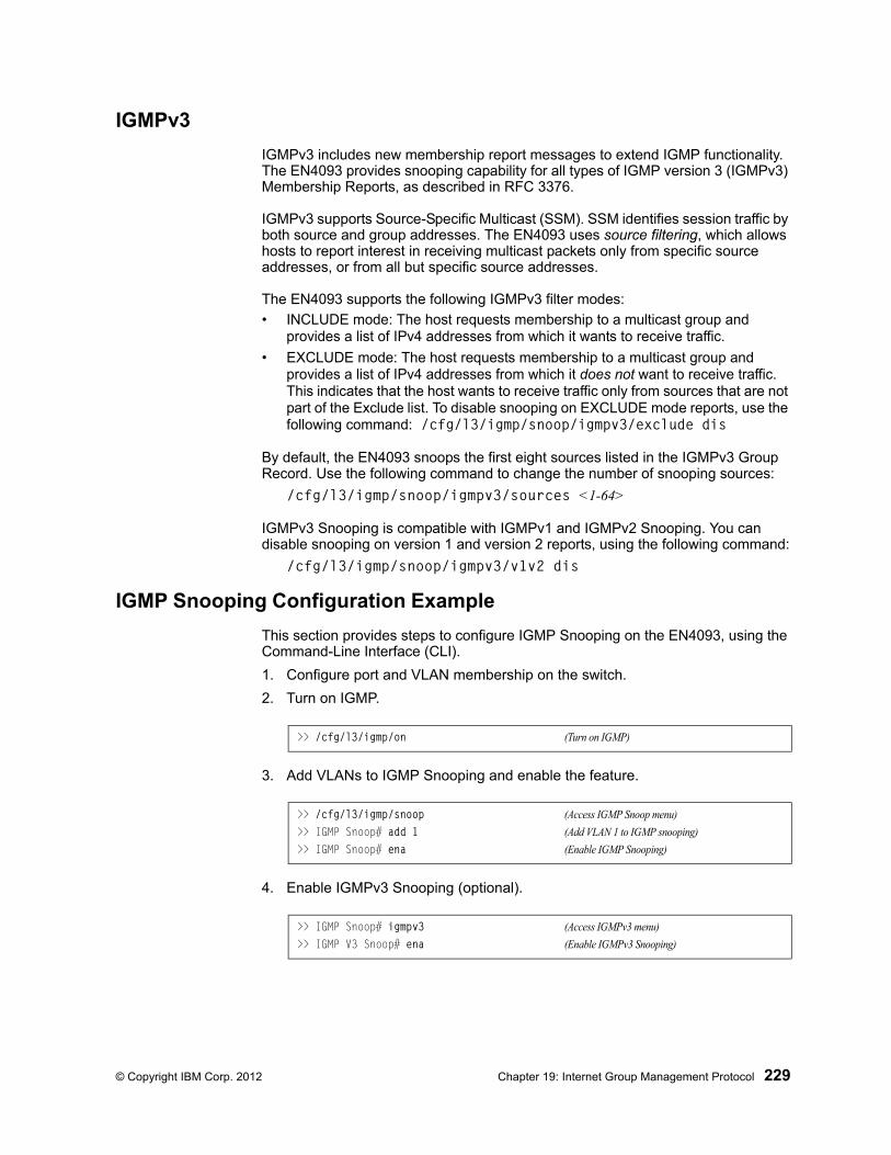
© Copyright IBM Corp. 2012 Chapter 19: Internet Group Management Protocol 229
IGMPv3
IGMPv3 includes new membership report messages to extend IGMP functionality. The EN4093 provides snooping capability for all types of IGMP version 3 (IGMPv3) Membership Reports, as described in RFC 3376.
IGMPv3 supports Source-Specific Multicast (SSM). SSM identifies session traffic by both source and group addresses. The EN4093 uses source filtering, which allows hosts to report interest in receiving multicast packets only from specific source addresses, or from all but specific source addresses.
The EN4093 supports the following IGMPv3 filter modes:
• INCLUDE mode: The host requests membership to a multicast group and provides a list of IPv4 addresses from which it wants to receive traffic.
• EXCLUDE mode: The host requests membership to a multicast group and provides a list of IPv4 addresses from which it does not want to receive traffic. This indicates that the host wants to receive traffic only from sources that are not part of the Exclude list. To disable snooping on EXCLUDE mode reports, use the following command: /cfg/l3/igmp/snoop/igmpv3/exclude dis
By default, the EN4093 snoops the first eight sources listed in the IGMPv3 Group Record. Use the following command to change the number of snooping sources:
/cfg/l3/igmp/snoop/igmpv3/sources <1-64>
IGMPv3 Snooping is compatible with IGMPv1 and IGMPv2 Snooping. You can disable snooping on version 1 and version 2 reports, using the following command:
/cfg/l3/igmp/snoop/igmpv3/v1v2 dis
IGMP Snooping Configuration Example
This section provides steps to configure IGMP Snooping on the EN4093, using the Command-Line Interface (CLI).
1. Configure port and VLAN membership on the switch.
2. Turn on IGMP.
3. Add VLANs to IGMP Snooping and enable the feature.
4. Enable IGMPv3 Snooping (optional).
>> /cfg/l3/igmp/on (Turn on IGMP)
>> /cfg/l3/igmp/snoop (Access IGMP Snoop menu)
>> IGMP Snoop# add 1 (Add VLAN 1 to IGMP snooping)
>> IGMP Snoop# ena (Enable IGMP Snooping)
>> IGMP Snoop# igmpv3 (Access IGMPv3 menu)
>> IGMP V3 Snoop# ena (Enable IGMPv3 Snooping)
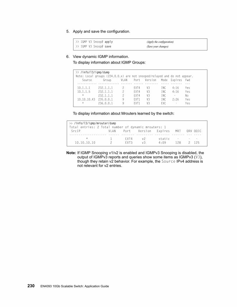
230 EN4093 10Gb Scalable Switch: Application Guide
5. Apply and save the configuration.
6. View dynamic IGMP information.
To display information about IGMP Groups:
To display information about Mrouters learned by the switch:
Note: If IGMP Snooping v1/v2 is enabled and IGMPv3 Snooping is disabled, the output of IGMPv3 reports and queries show some items as IGMPv3 (V3), though they retain v2 behavior. For example, the Source IPv4 address is not relevant for v2 entries.
>> IGMP V3 Snoop# apply (Apply the configuration)
>> IGMP V3 Snoop# save (Save your changes)
>> /info/l3/igmp/dumpNote: Local groups (224.0.0.x) are not snooped/relayed and do not appear. Source Group VLAN Port Version Mode Expires Fwd ------------ ------------- ------- ------ -------- ----- ------- --- 10.1.1.1 232.1.1.1 2 EXT4 V3 INC 4:16 Yes 10.1.1.5 232.1.1.1 2 EXT4 V3 INC 4:16 Yes * 232.1.1.1 2 EXT4 V3 INC - No 10.10.10.43 235.0.0.1 9 EXT1 V3 INC 2:26 Yes * 236.0.0.1 9 EXT1 V3 EXC - Yes
>> /info/l3/igmp/mrouter/dumpTotal entries: 2 Total number of dynamic mrouters: 1 SrcIP VLAN Port Version Expires MRT QRV QQIC-------------------- ------ ------- --------- -------- ------- --- ---- * 1 EXT4 v2 static - - - 10.10.10.10 2 EXT3 v3 4:09 128 2 125
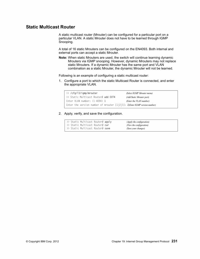
© Copyright IBM Corp. 2012 Chapter 19: Internet Group Management Protocol 231
Static Multicast Router
A static multicast router (Mrouter) can be configured for a particular port on a particular VLAN. A static Mrouter does not have to be learned through IGMP Snooping.
A total of 16 static Mrouters can be configured on the EN4093. Both internal and external ports can accept a static Mrouter.
Note: When static Mrouters are used, the switch will continue learning dynamic Mrouters via IGMP snooping. However, dynamic Mrouters may not replace static Mrouters. If a dynamic Mrouter has the same port and VLAN combination as a static Mrouter, the dynamic Mrouter will not be learned.
Following is an example of configuring a static multicast router:
1. Configure a port to which the static Multicast Router is connected, and enter the appropriate VLAN.
2. Apply, verify, and save the configuration.
>> /cfg/l3/igmp/mrouter (Select IGMP Mrouter menu)
>> Static Multicast Router# add EXT4 (Add Static Mrouter port)
Enter VLAN number: (1-4094) 1 (Enter the VLAN number)
Enter the version number of mrouter [1|2|3]: 2(Enter IGMP version number)
>> Static Multicast Router# apply (Apply the configuration)>> Static Multicast Router# cur (View the configuration)>> Static Multicast Router# save (Save your changes)
232 EN4093 10Gb Scalable Switch: Application Guide
IGMP Relay
The EN4093 can act as an IGMP Relay (or IGMP Proxy) device that relays IGMP multicast messages and traffic between an Mrouter and end stations. IGMP Relay allows the EN4093 to participate in network multicasts with no configuration of the various multicast routing protocols, so you can deploy it in the network with minimal effort.
To an IGMP host connected to the EN4093, IGMP Relay appears to be an IGMP multicast router (Mrouter). IGMP Relay sends Membership Queries to hosts, which respond by sending an IGMP response message. A host can also send an unsolicited Join message to the IGMP Relay.
To a multicast router, IGMP Relay appears as a host. The Mrouter sends IGMP host queries to IGMP Relay, and IGMP Relay responds by forwarding IGMP host reports and unsolicited join messages from its attached hosts.
IGMP Relay also forwards multicast traffic between the Mrouter and end stations, similar to IGMP Snooping.
You can configure up to two Mrouters to use with IGMP Relay. One Mrouter acts as the primary Mrouter, and one is the backup Mrouter. The EN4093 uses ICMP health checks to determine if the primary and backup mrouters are reachable.
Configuration Guidelines
Consider the following guidelines when you configure IGMP Relay:
• IGMP Relay is supported in stand-alone (non-stacking) mode only.
• IGMP Relay and IGMP Snooping are mutually exclusive—if you enable IGMP Relay, you must turn off IGMP Snooping.
• Add the upstream Mrouter VLAN to the IGMP Relay list, using the following command:
/cfg/l3/igmp/relay/add <VLAN number>
• If IGMP hosts reside on different VLANs, you must disable IGMP flooding (/cfg/l3/flooding/vlan <x>/flood d) and enable CPU forwarding (/cfg/l3/flooding/vlan <x>/cpu e) to ensure that multicast data is forwarded across the VLANs.
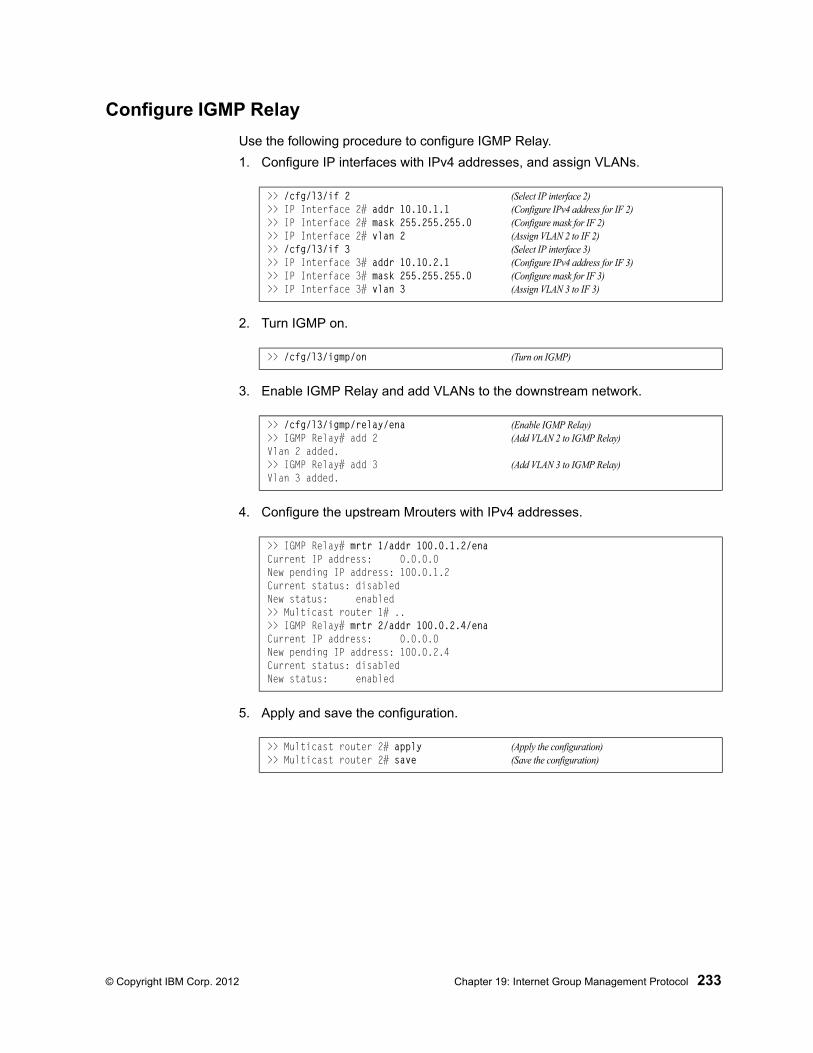
© Copyright IBM Corp. 2012 Chapter 19: Internet Group Management Protocol 233
Configure IGMP Relay
Use the following procedure to configure IGMP Relay.
1. Configure IP interfaces with IPv4 addresses, and assign VLANs.
2. Turn IGMP on.
3. Enable IGMP Relay and add VLANs to the downstream network.
4. Configure the upstream Mrouters with IPv4 addresses.
5. Apply and save the configuration.
>> /cfg/l3/if 2 (Select IP interface 2)>> IP Interface 2# addr 10.10.1.1 (Configure IPv4 address for IF 2)>> IP Interface 2# mask 255.255.255.0 (Configure mask for IF 2)>> IP Interface 2# vlan 2 (Assign VLAN 2 to IF 2)>> /cfg/l3/if 3 (Select IP interface 3)>> IP Interface 3# addr 10.10.2.1 (Configure IPv4 address for IF 3)>> IP Interface 3# mask 255.255.255.0 (Configure mask for IF 3)>> IP Interface 3# vlan 3 (Assign VLAN 3 to IF 3)
>> /cfg/l3/igmp/on (Turn on IGMP)
>> /cfg/l3/igmp/relay/ena (Enable IGMP Relay)>> IGMP Relay# add 2 (Add VLAN 2 to IGMP Relay)Vlan 2 added.>> IGMP Relay# add 3 (Add VLAN 3 to IGMP Relay)Vlan 3 added.
>> IGMP Relay# mrtr 1/addr 100.0.1.2/enaCurrent IP address: 0.0.0.0New pending IP address: 100.0.1.2Current status: disabledNew status: enabled>> Multicast router 1# ..>> IGMP Relay# mrtr 2/addr 100.0.2.4/enaCurrent IP address: 0.0.0.0New pending IP address: 100.0.2.4Current status: disabledNew status: enabled
>> Multicast router 2# apply (Apply the configuration)>> Multicast router 2# save (Save the configuration)
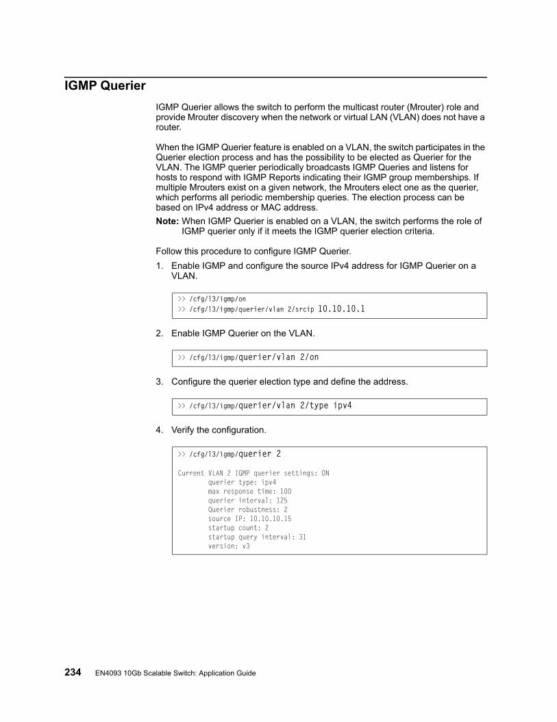
234 EN4093 10Gb Scalable Switch: Application Guide
IGMP Querier
IGMP Querier allows the switch to perform the multicast router (Mrouter) role and provide Mrouter discovery when the network or virtual LAN (VLAN) does not have a router.
When the IGMP Querier feature is enabled on a VLAN, the switch participates in the Querier election process and has the possibility to be elected as Querier for the VLAN. The IGMP querier periodically broadcasts IGMP Queries and listens for hosts to respond with IGMP Reports indicating their IGMP group memberships. If multiple Mrouters exist on a given network, the Mrouters elect one as the querier, which performs all periodic membership queries. The election process can be based on IPv4 address or MAC address.
Note: When IGMP Querier is enabled on a VLAN, the switch performs the role of IGMP querier only if it meets the IGMP querier election criteria.
Follow this procedure to configure IGMP Querier.
1. Enable IGMP and configure the source IPv4 address for IGMP Querier on a VLAN.
2. Enable IGMP Querier on the VLAN.
3. Configure the querier election type and define the address.
4. Verify the configuration.
>> /cfg/l3/igmp/on>> /cfg/l3/igmp/querier/vlan 2/srcip 10.10.10.1
>> /cfg/l3/igmp/querier/vlan 2/on
>> /cfg/l3/igmp/querier/vlan 2/type ipv4
>> /cfg/l3/igmp/querier 2
Current VLAN 2 IGMP querier settings: ON querier type: ipv4 max response time: 100 querier interval: 125 Querier robustness: 2 source IP: 10.10.10.15 startup count: 2 startup query interval: 31 version: v3
© Copyright IBM Corp. 2012 Chapter 19: Internet Group Management Protocol 235
Additional IGMP Features
The following topics are discussed in this section:
• “FastLeave” on page 235
• “IGMP Filtering” on page 235
FastLeave
In normal IGMP operation, when the switch receives an IGMPv2 leave message, it sends a Group-Specific Query to determine if any other devices in the same group (and on the same port) are still interested in the specified multicast group traffic. The switch removes the affiliated port from that particular group, if it does not receive an IGMP Membership Report within the query-response-interval.
With FastLeave enabled on the VLAN, a port can be removed immediately from the port list of the group entry when the IGMP Leave message is received, unless a multicast router was learned on the port.
Enable FastLeave only on VLANs that have only one host connected to each physical port.
IGMP Filtering
With IGMP Filtering, you can allow or deny a port to learn certain IGMP/IPMC groups. This allows you to restrict users from receiving certain multicast traffic.
If access to a multicast group is denied, IGMP Membership Reports from the port are dropped, and the port is not allowed to receive IPv4 multicast traffic from that group. If access to the multicast group is allowed, Membership Reports from the port are forwarded for normal processing.
To configure IGMP Filtering, you must globally enable IGMP filtering, define an IGMP filter, assign the filter to a port, and enable IGMP Filtering on the port. To define an IGMP filter, you must configure a range of IPv4 multicast groups, choose whether the filter will allow or deny multicast traffic for groups within the range, and enable the filter.
Configuring the Range
Each IGMP Filter allows you to set a start and end point that defines the range of IPv4 addresses upon which the filter takes action. Each IPv4 address in the range must be between 224.0.0.0 and 239.255.255.255.
Configuring the Action
Each IGMP filter can allow or deny IPv4 multicasts to the range of IPv4 addresses configured. If you configure the filter to deny IPv4 multicasts, then IGMP Membership Reports from multicast groups within the range are dropped. You can configure a secondary filter to allow IPv4 multicasts to a small range of addresses within a larger range that a primary filter is configured to deny. The two filters work together to allow IPv4 multicasts to a small subset of addresses within the larger range of addresses.
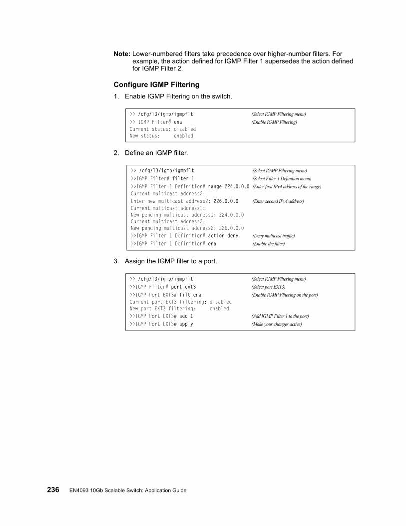
236 EN4093 10Gb Scalable Switch: Application Guide
Note: Lower-numbered filters take precedence over higher-number filters. For example, the action defined for IGMP Filter 1 supersedes the action defined for IGMP Filter 2.
Configure IGMP Filtering
1. Enable IGMP Filtering on the switch.
2. Define an IGMP filter.
3. Assign the IGMP filter to a port.
>> /cfg/l3/igmp/igmpflt (Select IGMP Filtering menu)
>> IGMP Filter# ena (Enable IGMP Filtering)Current status: disabledNew status: enabled
>> /cfg/l3/igmp/igmpflt (Select IGMP Filtering menu)
>>IGMP Filter# filter 1 (Select Filter 1 Definition menu)
>>IGMP Filter 1 Definition# range 224.0.0.0 (Enter first IPv4 address of the range)Current multicast address2:Enter new multicast address2: 226.0.0.0 (Enter second IPv4 address)Current multicast address1:New pending multicast address1: 224.0.0.0Current multicast address2:New pending multicast address2: 226.0.0.0>>IGMP Filter 1 Definition# action deny (Deny multicast traffic)
>>IGMP Filter 1 Definition# ena (Enable the filter)
>> /cfg/l3/igmp/igmpflt (Select IGMP Filtering menu)
>>IGMP Filter# port ext3 (Select port EXT3)
>>IGMP Port EXT3# filt ena (Enable IGMP Filtering on the port)Current port EXT3 filtering: disabledNew port EXT3 filtering: enabled>>IGMP Port EXT3# add 1 (Add IGMP Filter 1 to the port)
>>IGMP Port EXT3# apply (Make your changes active)

© Copyright IBM Corp. 2012 237
Chapter 20. Multicast Listener Discovery
Multicast Listener Discovery (MLD) is an IPv6 protocol that a host uses to request multicast data for a multicast group. An IPv6 router uses MLD to discover the presence of multicast listeners (nodes that want to receive multicast packets) on its directly attached links, and to discover specifically the multicast addresses that are of interest to those neighboring nodes.
MLD version 1 is derived from Internet Group Management Protocol version 2 (IGMPv2) and MLDv2 is derived from IGMPv3. MLD uses ICMPv6 (IP Protocol 58) message types. See RFC 2710 and RFC 3810 for details.
MLDv2 protocol, when compared to MLDv1, adds support for source filtering—the ability for a node to report interest in listening to packets only from specific source addresses, or from all but specific source addresses, sent to a particular multicast address. MLDv2 is interoperable with MLDv1. See RFC 3569 for details on Source-Specific Multicast (SSM).
The following topics are discussed in this chapter:
• “MLD Terms” on page 238
• “How MLD Works” on page 239
• “MLD Capacity and Default Values” on page 241
• “Configuring MLD” on page 242
238 IBM Flex System Fabric EN4093 10Gb Scalable Switch: Application Guide
MLD TermsFollowing are the commonly used MLD terms:
• Multicast traffic: Flow of data from one source to multiple destinations.
• Group: A multicast stream to which a host can join.
• Multicast Router (Mrouter): A router configured to make routing decisions for multicast traffic. The router identifies the type of packet received (unicast or multicast) and forwards the packet to the intended destination.
• Querier: An Mrouter that sends periodic query messages. Only one Mrouter on the subnet can be elected as the Querier.
• Multicast Listener Query: Messages sent by the Querier. There are three types of queries:
– General Query: Sent periodically to learn multicast address listeners from an attached link. EN4093 uses these queries to build and refresh the Multicast Address Listener state. General Queries are sent to the link-scope all-nodes multicast address (FF02::1), with a multicast address field of 0, and a maximum response delay of query response interval.
– Multicast Address Specific Query: Sent to learn if a specific multicast address has any listeners on an attached link. The multicast address field is set to the IPv6 multicast address.
– Multicast Address and Source Specific Query: Sent to learn if, for a specified multicast address, there are nodes still listening to a specific set of sources. Supported only in MLDv2.
Note: Multicast Address Specific Queries and Multicast Address and Source Specific Queries are sent only in response to State Change Reports, and never in response to Current State Reports.
• Multicast Listener Report: Sent by a host when it joins a multicast group, or in response to a Multicast Listener Query sent by the Querier. Hosts use these reports to indicate their current multicast listening state, or changes in the multicast listening state of their interfaces. These reports are of two types:
– Current State Report: Contains the current Multicast Address Listening State of the host.
– State Change Report: If the listening state of a host changes, the host immediately reports these changes through a State Change Report message. These reports contain either Filter Mode Change records and/or Source List Change records. State Change Reports are retransmitted several times to ensure all Mrouters receive it.
• Multicast Listener Done: Sent by a host when it wants to leave a multicast group. This message is sent to the link-scope all-routers IPv6 destination address of FF02::2. When an Mrouter receives a Multicast Listener Done message from the last member of the multicast address on a link, it stops forwarding traffic to this multicast address.
© Copyright IBM Corp. 2012 Chapter 20: Multicast Listener Discovery 239
How MLD WorksThe software uses the information obtained through MLD to maintain a list of multicast group memberships for each interface and forwards the multicast traffic only to interested listeners.
Without MLD, the switch forwards IPv6 multicast traffic through all ports, increasing network load. Following is an overview of operations when MLD is configured on EN4093:
• The switch acts as an Mrouter when MLDv1/v2 is configured and enabled on each of its directly attached links. If the switch has multiple interfaces connected to the same link, it operates the protocol on any one of the interfaces.
• If there are multiple Mrouters on the subnet, the Mrouter with the numerically lowest IPv6 address is elected as the Querier.
• The Querier sends general queries at short intervals to learn multicast address listener information from an attached link.
• Hosts respond to these queries by reporting their per-interface Multicast Address Listening state, through Current State Report messages sent to a specific multicast address that all MLD routers on the link listen to.
• If the listening state of a host changes, the host immediately reports these changes through a State Change Report message.
• The Querier sends a Multicast Address Specific Query to verify if hosts are listening to a specified multicast address or not. Similarly, if MLDv2 is configured, the Querier sends a Multicast Address and Source Specific Query to verify, for a specified multicast address, if hosts are listening to a specific set of sources, or not. MLDv2 listener report messages consists of Multicast Address Records:
– INCLUDE: to receive packets from source specified in the MLDv2 message
– EXCLUDE: to receive packets from all sources except the ones specified in the MLDv2 message
• A host can send a State Change Report to indicate its desire to stop listening to a particular multicast address (or source in MLDv2). The Querier then sends a multicast address specific query to verify if there are other listeners of the multicast address. If there aren’t any, the Mrouter deletes the multicast address from its Multicast Address Listener state and stops sending multicast traffic. Similarly in MLDv2, the Mrouter sends a Multicast Address and Source Specific Query to verify if, for a specified multicast address, there are hosts still listening to a specific set of sources.
EN4093 supports MLD versions 1 and 2.
Note: MLDv2 operates in version 1 compatibility mode when, in a specific network, not all hosts are configured with MLDv2.
240 IBM Flex System Fabric EN4093 10Gb Scalable Switch: Application Guide
FloodingWhen flood option is disabled, the unknown multicast traffic is discarded if no Mrouters are learned on the switch. You can set the flooding behavior by configuring the flood and cpu options. You can optimize the flooding to ensure that unknown IP multicast (IPMC) data packets are not dropped during the learning phase.
The flooding options include:
• flood: Enable hardware flooding in VLAN for the unregistered IPMC; This option is enabled by default.
• cpu: Enable sending unregistered IPMC to the Mrouter ports. However, during the learning period, there will be some packet loss. The cpu option is enabled by default. You must ensure that the flood and optflood options are disabled.
• optflood: Enable optimized flooding to allow sending the unregistered IPMC to the Mrouter ports without having any packet loss during the learning period; This option is disabled by default; When optflood is enabled, the flood and cpu settings are ignored.
The flooding parameters must be configured per VLAN. Enter the following command to set the flood or cpu options:
MLD QuerierAn Mrouter acts as a Querier and periodically (at short query intervals) sends query messages in the subnet. If there are multiple Mrouters in the subnet, only one can be the Querier. All Mrouters on the subnet listen to the messages sent by the multicast address listeners, and maintain the same multicast listening information state.
All MLDv2 queries are sent with the FE80::/64 link-local source address prefix.
Querier Election
Only one Mrouter can be the Querier per subnet. All other Mrouters will be non-Queriers. MLD versions 1 and 2 elect the Mrouter with the numerically lowest IPv6 address as the Querier.
If the switch is configured as an Mrouter on a subnet, it also acts as a Querier by default and sends multiple general queries. If the switch receives a general query from another Querier with a numerically lower IPv6 address, it sets the other querier present timer to the other querier present timeout, and changes its state to non-Querier. When the other querier present timer expires, it regains the Querier state and starts sending general queries.
Note: When MLD Querier is enabled on a VLAN, the switch performs the role of an MLD Querier only if it meets the MLD Querier election criteria.
>> # /cfg/l3/flooding/vlan <VLAN number>/flood <d/e>>> # /cfg/l3/flooding/vlan <VLAN number>/cpu <d/e>>> # /cfg/l3/flooding/vlan <VLAN number>/optflood <d/e>
© Copyright IBM Corp. 2012 Chapter 20: Multicast Listener Discovery 241
Dynamic MroutersThe switch learns Mrouters on the ingress VLANs of the MLD-enabled interface. All report or done messages are forwarded to these Mrouters. By default, the option of dynamically learning Mrouters is disabled. To enable it, use the following command:
MLD Capacity and Default ValuesTable 20 lists the maximum and minimum values of the EN4093 variables.
Table 21 lists the default settings for MLD features and variables.
>> Main# /cfg/l3/mld/if <interface number>/dmrtr enable
Table 20. EN4093 Capacity Table
Variable Maximum Value
IPv6 Multicast Entries 256
IPv6 Interfaces for MLD 8
Table 21. MLD Timers and Default Values
Field Default Value
Robustness Variable (RV) 2
Query Interval (QI) 125 seconds
Query Response Interval (QRI) 10 seconds
Multicast Address Listeners Interval (MALI)
260 seconds [derived: RV*QI+QRI]
Other Querier Present Interval [OQPT] 255 seconds [derived: RV*QI + ½ QRI]
Start up Query Interval [SQI] 31.25 seconds [derived: ¼ * QI]
Startup Query Count [SQC] 2 [derived: RV]
Last Listener Query Interval [LLQI] 1 second
Last Listener Query Count [LLQC] 2 [derived: RV]
Last Listener Query Time [LLQT] 2 seconds [derived: LLQI * LLQT]
Older Version Querier Present Timeout: [OVQPT]
260 seconds [derived: RV*QI+ QRI]
Older Version Host Present Interval [OVHPT]
260 seconds [derived: RV* QI+QRI]
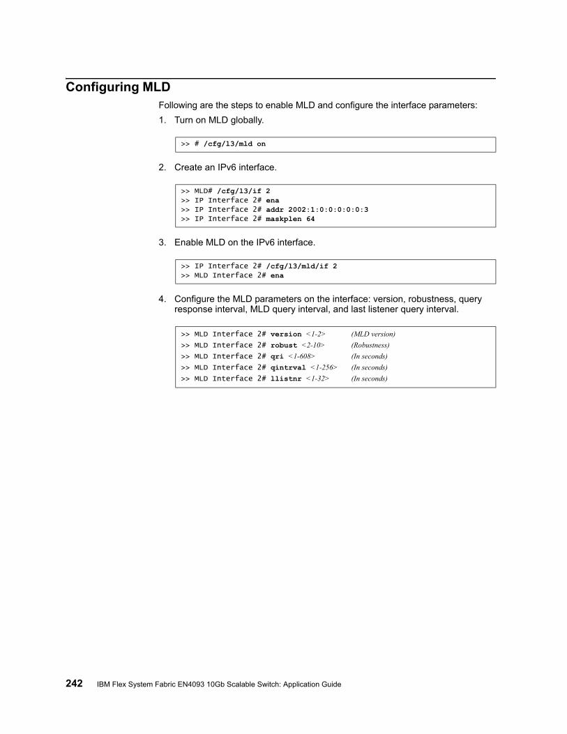
242 IBM Flex System Fabric EN4093 10Gb Scalable Switch: Application Guide
Configuring MLDFollowing are the steps to enable MLD and configure the interface parameters:
1. Turn on MLD globally.
2. Create an IPv6 interface.
3. Enable MLD on the IPv6 interface.
4. Configure the MLD parameters on the interface: version, robustness, query response interval, MLD query interval, and last listener query interval.
>> # /cfg/l3/mld on
>> MLD# /cfg/l3/if 2>> IP Interface 2# ena>> IP Interface 2# addr 2002:1:0:0:0:0:0:3>> IP Interface 2# maskplen 64
>> IP Interface 2# /cfg/l3/mld/if 2>> MLD Interface 2# ena
>> MLD Interface 2# version <1-2> (MLD version)
>> MLD Interface 2# robust <2-10> (Robustness)
>> MLD Interface 2# qri <1-608> (In seconds)
>> MLD Interface 2# qintrval <1-256> (In seconds)
>> MLD Interface 2# llistnr <1-32> (In seconds)
© Copyright IBM Corp. 2012 243
Chapter 21. Border Gateway Protocol
Border Gateway Protocol (BGP) is an Internet protocol that enables routers on an IPv4 network to share and advertise routing information with each other about the segments of the IPv4 address space they can access within their network and with routers on external networks. BGP allows you to decide what is the “best” route for a packet to take from your network to a destination on another network rather than simply setting a default route from your border router(s) to your upstream provider(s). BGP is defined in RFC 1771.
EN4093 10Gb Scalable Switches (EN4093s) can advertise their IP interfaces and IPv4 addresses using BGP and take BGP feeds from as many as 12 BGP router peers. This allows more resilience and flexibility in balancing traffic from the Internet.
Note: IBM Networking OS 7.2 does not support IPv6 for BGP.
The following topics are discussed in this section:
• “Internal Routing Versus External Routing” on page 243• “Forming BGP Peer Routers” on page 244• “What is a Route Map?” on page 245• “Aggregating Routes” on page 248• “Redistributing Routes” on page 249• “BGP Attributes” on page 249• “Selecting Route Paths in BGP” on page 250• “BGP Failover Configuration” on page 251• “Default Redistribution and Route Aggregation Example” on page 253
Internal Routing Versus External Routing
To ensure effective processing of network traffic, every router on your network needs to know how to send a packet (directly or indirectly) to any other location/destination in your network. This is referred to as internal routing and can be done with static routes or using active, internal dynamic routing protocols, such as RIP, RIPv2, and OSPF.
Static routes should have a higher degree of precedence than dynamic routing protocols. If the destination route is not in the route cache, then the packets are forwarded to the default gateway which may be incorrect if a dynamic routing protocol is enabled.
It is also useful to tell routers outside your network (upstream providers or peers) about the routes you can access in your network. External networks (those outside your own) that are under the same administrative control are referred to as autonomous systems (AS). Sharing of routing information between autonomous systems is known as external routing.
External BGP (eBGP) is used to exchange routes between different autonomous systems whereas internal BGP (iBGP) is used to exchange routes within the same autonomous system. An iBGP is a type of internal routing protocol you can use to do active routing inside your network. It also carries AS path information, which is important when you are an ISP or doing BGP transit.
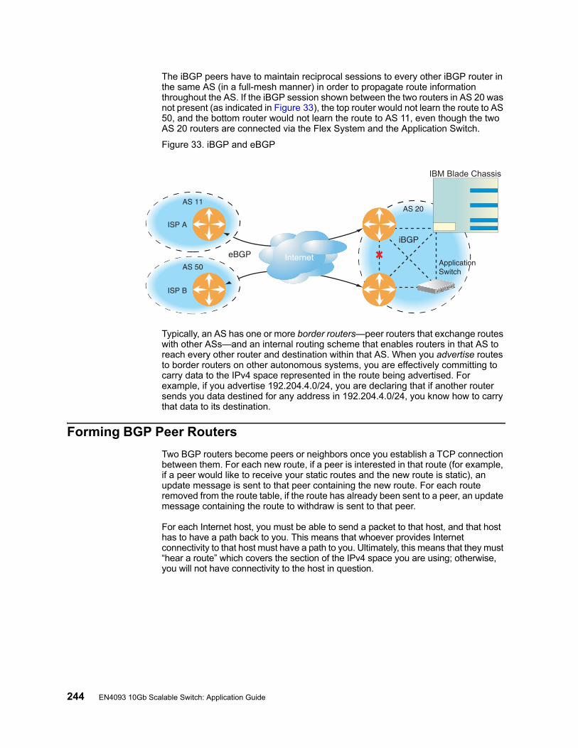
244 EN4093 10Gb Scalable Switch: Application Guide
The iBGP peers have to maintain reciprocal sessions to every other iBGP router in the same AS (in a full-mesh manner) in order to propagate route information throughout the AS. If the iBGP session shown between the two routers in AS 20 was not present (as indicated in Figure 33), the top router would not learn the route to AS 50, and the bottom router would not learn the route to AS 11, even though the two AS 20 routers are connected via the Flex System and the Application Switch.
Figure 33. iBGP and eBGP
Typically, an AS has one or more border routers—peer routers that exchange routes with other ASs—and an internal routing scheme that enables routers in that AS to reach every other router and destination within that AS. When you advertise routes to border routers on other autonomous systems, you are effectively committing to carry data to the IPv4 space represented in the route being advertised. For example, if you advertise 192.204.4.0/24, you are declaring that if another router sends you data destined for any address in 192.204.4.0/24, you know how to carry that data to its destination.
Forming BGP Peer Routers
Two BGP routers become peers or neighbors once you establish a TCP connection between them. For each new route, if a peer is interested in that route (for example, if a peer would like to receive your static routes and the new route is static), an update message is sent to that peer containing the new route. For each route removed from the route table, if the route has already been sent to a peer, an update message containing the route to withdraw is sent to that peer.
For each Internet host, you must be able to send a packet to that host, and that host has to have a path back to you. This means that whoever provides Internet connectivity to that host must have a path to you. Ultimately, this means that they must “hear a route” which covers the section of the IPv4 space you are using; otherwise, you will not have connectivity to the host in question.
Internet
BladeCenterIBM Blade Chassis
Internet
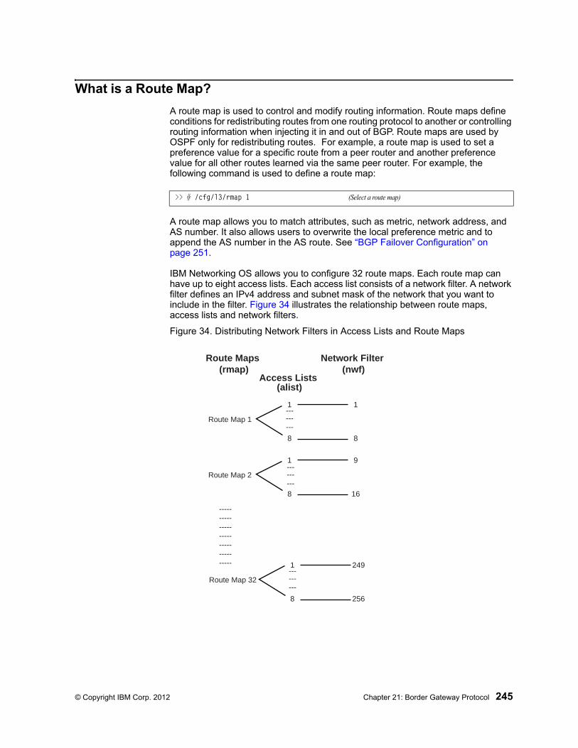
© Copyright IBM Corp. 2012 Chapter 21: Border Gateway Protocol 245
What is a Route Map?
A route map is used to control and modify routing information. Route maps define conditions for redistributing routes from one routing protocol to another or controlling routing information when injecting it in and out of BGP. Route maps are used by OSPF only for redistributing routes. For example, a route map is used to set a preference value for a specific route from a peer router and another preference value for all other routes learned via the same peer router. For example, the following command is used to define a route map:
A route map allows you to match attributes, such as metric, network address, and AS number. It also allows users to overwrite the local preference metric and to append the AS number in the AS route. See “BGP Failover Configuration” on page 251.
IBM Networking OS allows you to configure 32 route maps. Each route map can have up to eight access lists. Each access list consists of a network filter. A network filter defines an IPv4 address and subnet mask of the network that you want to include in the filter. Figure 34 illustrates the relationship between route maps, access lists and network filters.
Figure 34. Distributing Network Filters in Access Lists and Route Maps
>> # /cfg/l3/rmap 1 (Select a route map)
Access Lists (alist)
Network Filter (nwf)
Route Maps (rmap)
1
Route Map 1
8
1
8
1
Route Map 2
8
9
16
1
Route Map 32
8
249
256
-----------------------------------
------
---
------
---
------
---
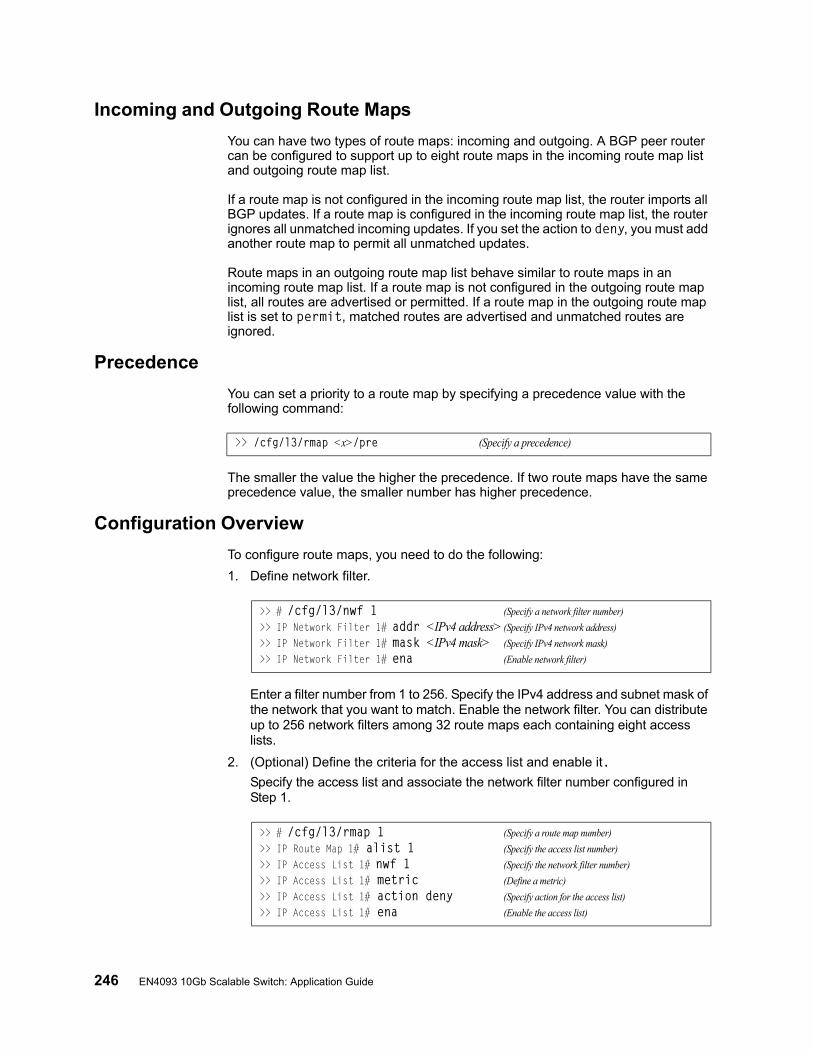
246 EN4093 10Gb Scalable Switch: Application Guide
Incoming and Outgoing Route Maps
You can have two types of route maps: incoming and outgoing. A BGP peer router can be configured to support up to eight route maps in the incoming route map list and outgoing route map list.
If a route map is not configured in the incoming route map list, the router imports all BGP updates. If a route map is configured in the incoming route map list, the router ignores all unmatched incoming updates. If you set the action to deny, you must add another route map to permit all unmatched updates.
Route maps in an outgoing route map list behave similar to route maps in an incoming route map list. If a route map is not configured in the outgoing route map list, all routes are advertised or permitted. If a route map in the outgoing route map list is set to permit, matched routes are advertised and unmatched routes are ignored.
Precedence
You can set a priority to a route map by specifying a precedence value with the following command:
The smaller the value the higher the precedence. If two route maps have the same precedence value, the smaller number has higher precedence.
Configuration Overview
To configure route maps, you need to do the following:
1. Define network filter.
Enter a filter number from 1 to 256. Specify the IPv4 address and subnet mask of the network that you want to match. Enable the network filter. You can distribute up to 256 network filters among 32 route maps each containing eight access lists.
2. (Optional) Define the criteria for the access list and enable it.Specify the access list and associate the network filter number configured in Step 1.
>> /cfg/l3/rmap <x>/pre (Specify a precedence)
>> # /cfg/l3/nwf 1 (Specify a network filter number)
>> IP Network Filter 1# addr <IPv4 address> (Specify IPv4 network address)
>> IP Network Filter 1# mask <IPv4 mask> (Specify IPv4 network mask)
>> IP Network Filter 1# ena (Enable network filter)
>> # /cfg/l3/rmap 1 (Specify a route map number)
>> IP Route Map 1# alist 1 (Specify the access list number)
>> IP Access List 1# nwf 1 (Specify the network filter number)
>> IP Access List 1# metric (Define a metric)
>> IP Access List 1# action deny (Specify action for the access list)
>> IP Access List 1# ena (Enable the access list)

© Copyright IBM Corp. 2012 Chapter 21: Border Gateway Protocol 247
Steps 2 and 3 are optional, depending on the criteria that you want to match. In Step 2, the network filter number is used to match the subnets defined in the network filter. In Step 3, the autonomous system number is used to match the subnets. Or, you can use both (Step 2 and Step 3) criteria: access list (network filter) and access path (AS filter) to configure the route maps.
3. (Optional) Configure the attributes in the AS filter menu.
4. Set up the BGP attributes.
If you want to overwrite the attributes that the peer router is sending, then define the following BGP attributes:
– Specify the AS numbers that you want to prepend to a matched route and the local preference for the matched route.
– Specify the metric [Multi Exit Discriminator (MED)] for the matched route.
5. Enable the route map.
6. Turn BGP on.
7. Assign the route map to a peer router.
Select the peer router and then add the route map to the incoming route map list,
or to the outgoing route map list.
8. Apply and save the configuration.
>> # cfg/l3/rmap 1/aspath 1 (Specify the attributes in the filter)
>> AS Filter 1# as 1 (Specify the AS number)
>> AS Filter 1# action deny (Specify the action for the filter)
>> AS Filter 1# ena (Enable the AS filter)
>> # cfg/l3/rmap 1 (Specify a route map number)
>> IP Route Map 1# ap (Specify the AS numbers to prepend)
>> IP Route Map 1# lp (Specify the local preference)
>> IP Route Map 1# metric (Specify the metric)
>> # cfg/l3/rmap 1/en (Enable the route map)
>> # cfg/l3/bgp/on (Globally turn BGP on)
>> Border Gateway Protocol# peer 1/addi (Add to the incoming route map)
>> Border Gateway Protocol# peer 1/addo (Add to the outgoing route map)
>> Border Gateway Protocol# apply (Apply the configuration)
>> Border Gateway Protocol# save (Save your changes)
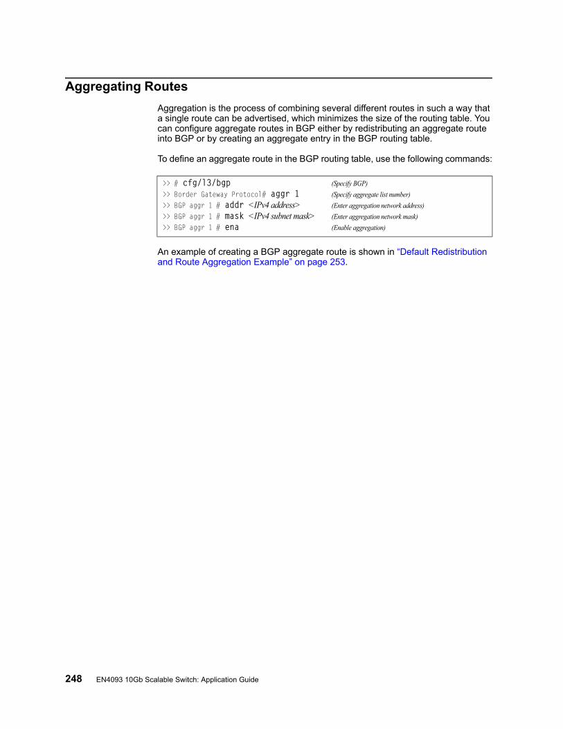
248 EN4093 10Gb Scalable Switch: Application Guide
Aggregating Routes
Aggregation is the process of combining several different routes in such a way that a single route can be advertised, which minimizes the size of the routing table. You can configure aggregate routes in BGP either by redistributing an aggregate route into BGP or by creating an aggregate entry in the BGP routing table.
To define an aggregate route in the BGP routing table, use the following commands:
An example of creating a BGP aggregate route is shown in “Default Redistribution and Route Aggregation Example” on page 253.
>> # cfg/l3/bgp (Specify BGP)
>> Border Gateway Protocol# aggr 1 (Specify aggregate list number)
>> BGP aggr 1 # addr <IPv4 address> (Enter aggregation network address)
>> BGP aggr 1 # mask <IPv4 subnet mask> (Enter aggregation network mask)
>> BGP aggr 1 # ena (Enable aggregation)
© Copyright IBM Corp. 2012 Chapter 21: Border Gateway Protocol 249
Redistributing Routes
In addition to running multiple routing protocols simultaneously, IBM Networking OS software can redistribute information from one routing protocol to another. For example, you can instruct the switch to use BGP to re-advertise static routes. This applies to all of the IP-based routing protocols.
You can also conditionally control the redistribution of routes between routing domains by defining a method known as route maps between the two domains. For more information on route maps, see “What is a Route Map?” on page 245. Redistributing routes is another way of providing policy control over whether to export OSPF routes, fixed routes, and static routes. For an example configuration, see “Default Redistribution and Route Aggregation Example” on page 253.
Default routes can be configured using the following methods:
• Import• Originate—The router sends a default route to peers if it does not have any
default routes in its routing table.• Redistribute—Default routes are either configured through the default gateway
or learned via other protocols and redistributed to peer routers. If the default routes are from the default gateway, enable the static routes because default routes from the default gateway are static routes. Similarly, if the routes are learned from another routing protocol, make sure you enable that protocol for redistribution.
• None
BGP Attributes
The following two BGP attributes are discussed in this section: Local preference and metric (Multi-Exit Discriminator).
Local Preference Attribute
When there are multiple paths to the same destination, the local preference attribute indicates the preferred path. The path with the higher preference is preferred (the default value of the local preference attribute is 100). Unlike the weight attribute, which is only relevant to the local router, the local preference attribute is part of the routing update and is exchanged among routers in the same AS.
The local preference attribute can be set in one of two ways:
• /cfg/l3/bgp/prefThis command uses the BGP default local preference method, affecting the outbound direction only.
• /cfg/l3/rmap/lpThis command uses the route map local preference method, which affects both inbound and outbound directions.
250 EN4093 10Gb Scalable Switch: Application Guide
Metric (Multi-Exit Discriminator) Attribute
This attribute is a hint to external neighbors about the preferred path into an AS when there are multiple entry points. A lower metric value is preferred over a higher metric value. The default value of the metric attribute is 0.
Unlike local preference, the metric attribute is exchanged between ASs; however, a metric attribute that comes into an AS does not leave the AS.
When an update enters the AS with a certain metric value, that value is used for decision making within the AS. When BGP sends that update to another AS, the metric is reset to 0.
Unless otherwise specified, the router compares metric attributes for paths from external neighbors that are in the same AS.
Selecting Route Paths in BGP
BGP selects only one path as the best path. It does not rely on metric attributes to determine the best path. When the same network is learned via more than one BGP peer, BGP uses its policy for selecting the best route to that network. The BGP implementation on the EN4093 uses the following criteria to select a path when the same route is received from multiple peers.
1. Local fixed and static routes are preferred over learned routes.
2. With iBGP peers, routes with higher local preference values are selected.
3. In the case of multiple routes of equal preference, the route with lower AS path weight is selected.
AS path weight = 128 x AS path length (number of autonomous systems traversed).
4. In the case of equal weight and routes learned from peers that reside in the same AS, the lower metric is selected.
Note: A route with a metric is preferred over a route without a metric.
5. The lower cost to the next hop of routes is selected.
6. In the case of equal cost, the eBGP route is preferred over iBGP.
7. If all routes are from eBGP, the route with the lower router ID is selected.
When the path is selected, BGP puts the selected path in its routing table and propagates the path to its neighbors.
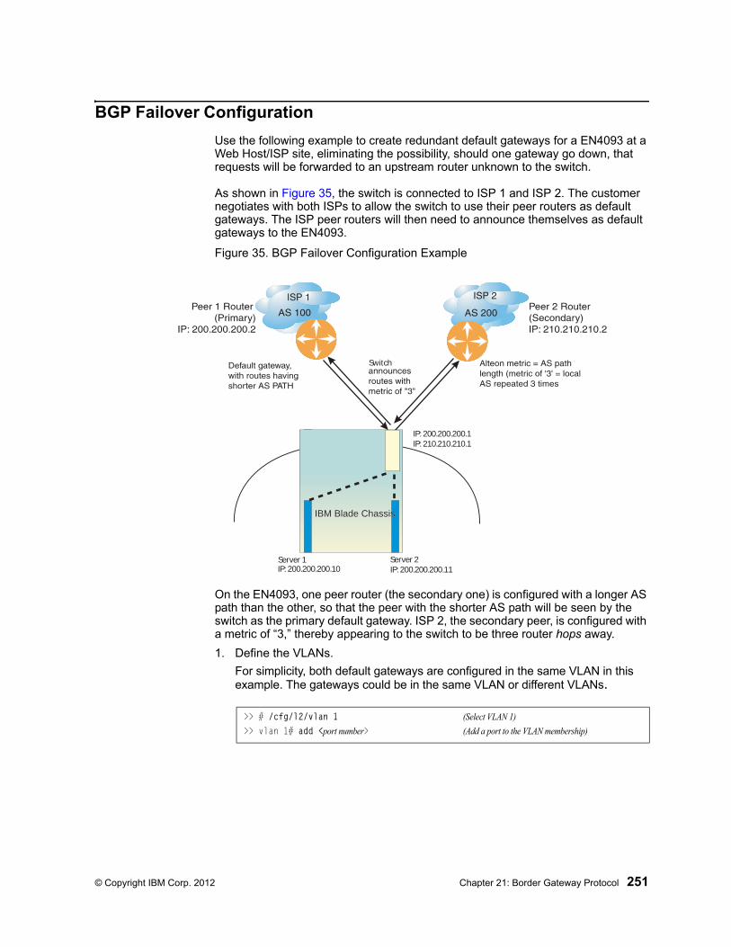
© Copyright IBM Corp. 2012 Chapter 21: Border Gateway Protocol 251
BGP Failover Configuration
Use the following example to create redundant default gateways for a EN4093 at a Web Host/ISP site, eliminating the possibility, should one gateway go down, that requests will be forwarded to an upstream router unknown to the switch.
As shown in Figure 35, the switch is connected to ISP 1 and ISP 2. The customer negotiates with both ISPs to allow the switch to use their peer routers as default gateways. The ISP peer routers will then need to announce themselves as default gateways to the EN4093.
Figure 35. BGP Failover Configuration Example
On the EN4093, one peer router (the secondary one) is configured with a longer AS path than the other, so that the peer with the shorter AS path will be seen by the switch as the primary default gateway. ISP 2, the secondary peer, is configured with a metric of “3,” thereby appearing to the switch to be three router hops away.
1. Define the VLANs.
For simplicity, both default gateways are configured in the same VLAN in this example. The gateways could be in the same VLAN or different VLANs.
IBM Blade ChassisIBM Blade Chassis
Switch
Server 1IP: 200.200.200.10
Server 2IP: 200.200.200.11
IP: 200.200.200.1IP: 210.210.210.1
>> # /cfg/l2/vlan 1 (Select VLAN 1)
>> vlan 1# add <port number> (Add a port to the VLAN membership)

252 EN4093 10Gb Scalable Switch: Application Guide
2. Define the IP interfaces with IPv4 addresses.
The switch will need an IP interface for each default gateway to which it will be connected. Each interface must be placed in the appropriate VLAN. These interfaces will be used as the primary and secondary default gateways for the switch.
3. Enable IP forwarding.
IP forwarding is turned on by default and is used for VLAN-to-VLAN (non-BGP) routing. Make sure IP forwarding is on if the default gateways are on different subnets or if the switch is connected to different subnets and those subnets need to communicate through the switch (which they almost always do).
Note: To help eliminate the possibility for a Denial of Service (DoS) attack, the forwarding of directed broadcasts is disabled by default.
4. Configure BGP peer router 1 and 2.
5. On the switch, apply and save your configuration changes.
>> # /cfg/l3/if 1 (Select interface 1)>> IP Interface 1# ena (Enable switch interface 1)>> IP Interface 1# addr 200.200.200.1 (Configure IPv4 address of interface 1)>> IP Interface 1# mask 255.255.255.0 (Configure IPv4 subnet address mask)>> IP Interface 1# ../if 2 (Select interface 2)>> IP Interface 2# ena (Enable switch interface 2)>> IP Interface 2# addr 210.210.210.1 (Configure IPv4 address of interface 2)>> IP Interface 2# mask 255.255.255.0 (Configure IPv4 subnet address mask)
>> # /cfg/l3/frwd/on (Enable IP forwarding)
>> # /cfg/l3/bgp/peer 1 (Select BGP peer router 1)>> BGP Peer 1# ena (Enable this peer configuration)>> BGP Peer 1# addr 200.200.200.2 (Set IPv4 address for peer router 1)>> BGP Peer 1# ras 100 (Set remote AS number)>> BGP Peer 1# /cfg/l3/bgp/peer 2 (Select BGP peer router 2)>> BGP Peer 2# ena (Enable this peer configuration)>> BGP Peer 2# addr 210.210.210.2 (Set IPv4 address for peer router 2)>> BGP Peer 2# ras 200 (Set remote AS number)
>> BGP Peer 2# apply (Make your changes active)>> save (Save for restore after reboot)
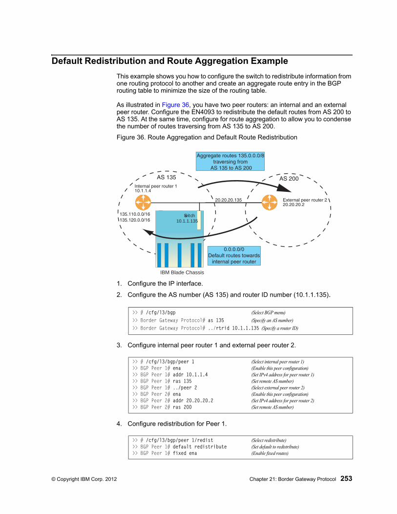
© Copyright IBM Corp. 2012 Chapter 21: Border Gateway Protocol 253
Default Redistribution and Route Aggregation Example
This example shows you how to configure the switch to redistribute information from one routing protocol to another and create an aggregate route entry in the BGP routing table to minimize the size of the routing table.
As illustrated in Figure 36, you have two peer routers: an internal and an external peer router. Configure the EN4093 to redistribute the default routes from AS 200 to AS 135. At the same time, configure for route aggregation to allow you to condense the number of routes traversing from AS 135 to AS 200.
Figure 36. Route Aggregation and Default Route Redistribution
1. Configure the IP interface.
2. Configure the AS number (AS 135) and router ID number (10.1.1.135).
3. Configure internal peer router 1 and external peer router 2.
4. Configure redistribution for Peer 1.
BladeCenterIBM Blade Chassis
Switch10.1.1.135
>> # /cfg/l3/bgp (Select BGP menu)
>> Border Gateway Protocol# as 135 (Specify an AS number)
>> Border Gateway Protocol# ../rtrid 10.1.1.135 (Specify a router ID)
>> # /cfg/l3/bgp/peer 1 (Select internal peer router 1)>> BGP Peer 1# ena (Enable this peer configuration)>> BGP Peer 1# addr 10.1.1.4 (Set IPv4 address for peer router 1)>> BGP Peer 1# ras 135 (Set remote AS number)>> BGP Peer 1# ../peer 2 (Select external peer router 2)>> BGP Peer 2# ena (Enable this peer configuration)>> BGP Peer 2# addr 20.20.20.2 (Set IPv4 address for peer router 2)>> BGP Peer 2# ras 200 (Set remote AS number)
>> # /cfg/l3/bgp/peer 1/redist (Select redistribute)>> BGP Peer 1# default redistribute (Set default to redistribute)>> BGP Peer 1# fixed ena (Enable fixed routes)

254 EN4093 10Gb Scalable Switch: Application Guide
5. Configure aggregation policy control.
Configure the routes that you want aggregated.
>> # /cfg/l3/bgp/aggr 1 (Set aggregation number)>> BGP aggr 1# addr 135.0.0.0 (Add IPv4 address to aggregate 1)>> BGP Peer 1# mask 255.0.0.0 (Add IPv4 mask to aggregate 1)
© Copyright IBM Corp. 2012 255
Chapter 22. OSPF
IBM Networking OS supports the Open Shortest Path First (OSPF) routing protocol. The IBM Networking OS implementation conforms to the OSPF version 2 specifications detailed in Internet RFC 1583, and OSPF version 3 specifications in RFC 2740. The following sections discuss OSPF support for the EN4093 10Gb Scalable Switch (EN4093):
• “OSPFv2 Overview” on page 256. This section provides information on OSPFv2 concepts, such as types of OSPF areas, types of routing devices, neighbors, adjacencies, link state database, authentication, and internal versus external routing.
• “OSPFv2 Implementation in IBM Networking OS” on page 261. This section describes how OSPFv2 is implemented in IBM Networking OS, such as configuration parameters, electing the designated router, summarizing routes, defining route maps and so forth.
• “OSPFv2 Configuration Examples” on page 269. This section provides step-by-step instructions on configuring differentOSPFv2 examples:
– Creating a simple OSPF domain
– Creating virtual links
– Summarizing routes
• “OSPFv3 Implementation in IBM Networking OS” on page 277. This section describes differences and additional features found in OSPFv3.
256 EN4093 10Gb Scalable Switch: Application Guide
OSPFv2 Overview
OSPF is designed for routing traffic within a single IP domain called an Autonomous System (AS). The AS can be divided into smaller logical units known as areas.
All routing devices maintain link information in their own Link State Database (LSDB). The LSDB for all routing devices within an area is identical but is not exchanged between different areas. Only routing updates are exchanged between areas, thereby significantly reducing the overhead for maintaining routing information on a large, dynamic network.
The following sections describe key OSPF concepts.
Types of OSPF Areas
An AS can be broken into logical units known as areas. In any AS with multiple areas, one area must be designated as area 0, known as the backbone. The backbone acts as the central OSPF area. All other areas in the AS must be connected to the backbone. Areas inject summary routing information into the backbone, which then distributes it to other areas as needed.
As shown in Figure 37, OSPF defines the following types of areas:
• Stub Area—an area that is connected to only one other area. External route information is not distributed into stub areas.
• Not-So-Stubby-Area (NSSA)—similar to a stub area with additional capabilities. Routes originating from within the NSSA can be propagated to adjacent transit and backbone areas. External routes from outside the AS can be advertised within the NSSA but are not distributed into other areas.
• Transit Area—an area that allows area summary information to be exchanged between routing devices. The backbone (area 0), any area that contains a virtual link to connect two areas, and any area that is not a stub area or an NSSA are considered transit areas.
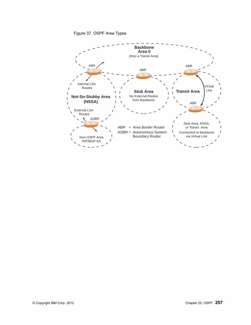
© Copyright IBM Corp. 2012 Chapter 22: OSPF 257
Figure 37. OSPF Area Types
BackboneArea 0
Stub AreaNot-So-Stubby Area
(NSSA)
Transit AreaNo External Routes
from Backbone
Stub Area, NSSA,or Transit Area
Connected to Backbonevia Virtual Link
(Also a Transit Area)
External LSA Routes
Internal LSA Routes
ABR ABRABR
ASBR
Non-OSPF AreaRIP/BGP AS
VirtualLink
ABR
ABR = Area Border RouterASBR = Autonomous System
Boundary Router
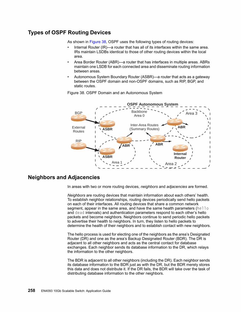
258 EN4093 10Gb Scalable Switch: Application Guide
Types of OSPF Routing Devices
As shown in Figure 38, OSPF uses the following types of routing devices:
• Internal Router (IR)—a router that has all of its interfaces within the same area. IRs maintain LSDBs identical to those of other routing devices within the local area.
• Area Border Router (ABR)—a router that has interfaces in multiple areas. ABRs maintain one LSDB for each connected area and disseminate routing information between areas.
• Autonomous System Boundary Router (ASBR)—a router that acts as a gateway between the OSPF domain and non-OSPF domains, such as RIP, BGP, and static routes.
Figure 38. OSPF Domain and an Autonomous System
Neighbors and Adjacencies
In areas with two or more routing devices, neighbors and adjacencies are formed.
Neighbors are routing devices that maintain information about each others’ health. To establish neighbor relationships, routing devices periodically send hello packets on each of their interfaces. All routing devices that share a common network segment, appear in the same area, and have the same health parameters (hello and dead intervals) and authentication parameters respond to each other’s hello packets and become neighbors. Neighbors continue to send periodic hello packets to advertise their health to neighbors. In turn, they listen to hello packets to determine the health of their neighbors and to establish contact with new neighbors.
The hello process is used for electing one of the neighbors as the area’s Designated Router (DR) and one as the area’s Backup Designated Router (BDR). The DR is adjacent to all other neighbors and acts as the central contact for database exchanges. Each neighbor sends its database information to the DR, which relays the information to the other neighbors.
The BDR is adjacent to all other neighbors (including the DR). Each neighbor sends its database information to the BDR just as with the DR, but the BDR merely stores this data and does not distribute it. If the DR fails, the BDR will take over the task of distributing database information to the other neighbors.
BackboneArea 0
Area 3
Area 2Area 1
Inter-Area Routes(Summary Routes) ABR
ABRABR
ASBR
InternalRouterASBR
ExternalRoutes
BGP
RIP
OSPF Autonomous System

© Copyright IBM Corp. 2012 Chapter 22: OSPF 259
The Link-State Database
OSPF is a link-state routing protocol. A link represents an interface (or routable path) from the routing device. By establishing an adjacency with the DR, each routing device in an OSPF area maintains an identical Link-State Database (LSDB) describing the network topology for its area.
Each routing device transmits a Link-State Advertisement (LSA) on each of its active interfaces. LSAs are entered into the LSDB of each routing device. OSPF uses flooding to distribute LSAs between routing devices. Interfaces may also be passive. Passive interfaces send LSAs to active interfaces, but do not receive LSAs, hello packets, or any other OSPF protocol information from active interfaces. Passive interfaces behave as stub networks, allowing OSPF routing devices to be aware of devices that do otherwise participate in OSPF (either because they do not support it, or because the administrator chooses to restrict OSPF traffic exchange or transit).
When LSAs result in changes to the routing device’s LSDB, the routing device forwards the changes to the adjacent neighbors (the DR and BDR) for distribution to the other neighbors.
OSPF routing updates occur only when changes occur, instead of periodically. For each new route, if an adjacency is interested in that route (for example, if configured to receive static routes and the new route is indeed static), an update message containing the new route is sent to the adjacency. For each route removed from the route table, if the route has already been sent to an adjacency, an update message containing the route to withdraw is sent.

260 EN4093 10Gb Scalable Switch: Application Guide
The Shortest Path First Tree
The routing devices use a link-state algorithm (Dijkstra’s algorithm) to calculate the shortest path to all known destinations, based on the cumulative cost required to reach the destination.
The cost of an individual interface in OSPF is an indication of the overhead required to send packets across it. The cost is inversely proportional to the bandwidth of the interface. A lower cost indicates a higher bandwidth.
Internal Versus External Routing
To ensure effective processing of network traffic, every routing device on your network needs to know how to send a packet (directly or indirectly) to any other location/destination in your network. This is referred to as internal routing and can be done with static routes or using active internal routing protocols, such as OSPF, RIP, or RIPv2.
It is also useful to tell routers outside your network (upstream providers or peers) about the routes you have access to in your network. Sharing of routing information between autonomous systems is known as external routing.
Typically, an AS will have one or more border routers (peer routers that exchange routes with other OSPF networks) as well as an internal routing system enabling every router in that AS to reach every other router and destination within that AS.
When a routing device advertises routes to boundary routers on other autonomous systems, it is effectively committing to carry data to the IP space represented in the route being advertised. For example, if the routing device advertises 192.204.4.0/24, it is declaring that if another router sends data destined for any address in the 192.204.4.0/24 range, it will carry that data to its destination.
© Copyright IBM Corp. 2012 Chapter 22: OSPF 261
OSPFv2 Implementation in IBM Networking OS
IBM Networking OS supports a single instance of OSPF and up to 4K routes on the network. The following sections describe OSPF implementation in IBM Networking OS:
• “Configurable Parameters” on page 261• “Defining Areas” on page 261• “Interface Cost” on page 263• “Electing the Designated Router and Backup” on page 263• “Summarizing Routes” on page 264• “Default Routes” on page 264• “Virtual Links” on page 265• “Router ID” on page 266• “Authentication” on page 266
Configurable Parameters
In IBM Networking OS, OSPF parameters can be configured through the Command Line Interfaces (CLI/ISCLI), Browser-Based Interface (BBI), or through SNMP. For more information, see “Switch Administration” on page 9.”
The CLI supports the following parameters: interface output cost, interface priority, dead and hello intervals, retransmission interval, and interface transmit delay.
In addition to the above parameters, you can also specify the following:
• Shortest Path First (SPF) interval—Time interval between successive calculations of the shortest path tree using the Dijkstra’s algorithm.
• Stub area metric—A stub area can be configured to send a numeric metric value such that all routes received via that stub area carry the configured metric to potentially influence routing decisions.
• Default routes—Default routes with weight metrics can be manually injected into transit areas. This helps establish a preferred route when multiple routing devices exist between two areas. It also helps route traffic to external networks.
• Passive—When enabled, the interface sends LSAs to upstream devices, but does not otherwise participate in OSPF protocol exchanges.
• Point-to-Point—For LANs that have only two OSPF routing agents (the EN4093 and one other device), this option allows the switch to significantly reduce the amount of routing information it must carry and manage.
Defining Areas
If you are configuring multiple areas in your OSPF domain, one of the areas must be designated as area 0, known as the backbone. The backbone is the central OSPF area and is usually physically connected to all other areas. The areas inject routing information into the backbone which, in turn, disseminates the information into other areas.
Since the backbone connects the areas in your network, it must be a contiguous area. If the backbone is partitioned (possibly as a result of joining separate OSPF networks), parts of the AS will be unreachable, and you will need to configure virtual links to reconnect the partitioned areas (see “Virtual Links” on page 265).

262 EN4093 10Gb Scalable Switch: Application Guide
Up to three OSPF areas can be connected to the EN4093 with IBM Networking OS software. To configure an area, the OSPF number must be defined and then attached to a network interface on the switch. The full process is explained in the following sections.
An OSPF area is defined by assigning two pieces of information: an area index and an area ID. The commands to define and enable an OSPF area are as follows:
Note: The aindex option above is an arbitrary index used only on the switch and does not represent the actual OSPF area number. The actual OSPF area number is defined in the areaid portion of the command as explained in the following sections.
Assigning the Area Index
The aindex <area index> option is actually just an arbitrary index (0-2) used only by the EN4093. This index does not necessarily represent the OSPF area number, though for configuration simplicity, it should where possible.
For example, both of the following sets of commands define OSPF area 0 (the backbone) and area 1 because that information is held in the area ID portion of the command. However, the first set of commands is easier to maintain because the arbitrary area indexes agree with the area IDs:
• Area index and area ID agree
/cfg/l3/ospf/aindex 0/areaid 0.0.0.0 (Use index 0 to set area 0 in ID octet format)/cfg/l3/ospf/aindex 1/areaid 0.0.0.1 (Use index 1 to set area 1 in ID octet format)
• Area index set to an arbitrary value
/cfg/l3/ospf/aindex 1/areaid 0.0.0.0 (Use index 1 to set area 0 in ID octet format)/cfg/l3/ospf/aindex 2/areaid 0.0.0.1 (Use index 2 to set area 1 in ID octet format)
Using the Area ID to Assign the OSPF Area Number
The OSPF area number is defined in the areaid <IP address> option. The octet format is used in order to be compatible with two different systems of notation used by other OSPF network vendors. There are two valid ways to designate an area ID:
• Placing the area number in the last octet (0.0.0.n)
Most common OSPF vendors express the area ID number as a single number. For example, the Cisco IOS-based router command “network 1.1.1.0 0.0.0.255 area 1” defines the area number simply as “area 1.” On the EN4093, using the last octet in the area ID, “area 1” is equivalent to “areaid 0.0.0.1”.
• Multi-octet (IP address)
Some OSPF vendors express the area ID number in multi-octet format. For example, “area 2.2.2.2” represents OSPF area 2 and can be specified directly on the EN4093 as “areaid 2.2.2.2”.
Note: Although both types of area ID formats are supported, be sure that the area IDs are in the same format throughout an area.
>> # /cfg/l3/ospf/aindex <area index>/areaid <n.n.n.n>/ena

© Copyright IBM Corp. 2012 Chapter 22: OSPF 263
Attaching an Area to a Network
Once an OSPF area has been defined, it must be associated with a network. To attach the area to a network, you must assign the OSPF area index to an IP interface that participates in the area. The format for the command is as follows:
For example, the following commands could be used to configure IPv4 interface 14 for a presence on the IPv4 10.10.10.1/24 network, to define OSPF area 1, and to attach the area to the network:
Note: OSPFv2 supports IPv4 only. IPv6 is supported in OSPFv3 (see “OSPFv3 Implementation in IBM Networking OS” on page 277).
Interface Cost
The OSPF link-state algorithm (Dijkstra’s algorithm) places each routing device at the root of a tree and determines the cumulative cost required to reach each destination. Usually, the cost is inversely proportional to the bandwidth of the interface. Low cost indicates high bandwidth. You can manually enter the cost for the output route with the following command:
Electing the Designated Router and Backup
In any area with more than two routing devices, a Designated Router (DR) is elected as the central contact for database exchanges among neighbors, and a Backup Designated Router (BDR) is elected in case the DR fails.
DR and BDR elections are made through the hello process. The election can be influenced by assigning a priority value to the OSPF interfaces on the EN4093. The command is as follows:
A priority value of 255 is the highest, and 1 is the lowest. A priority value of 0 specifies that the interface cannot be used as a DR or BDR. In case of a tie, the routing device with the highest router ID wins. Interfaces configured as passive do not participate in the DR or BDR election process:
>> # /cfg/l3/ospf/if <interface number>/aindex <area index>
>> # /cfg/l3/if 14 (Select menu for IP interface 14)>> IP Interface 14# addr 10.10.10.1 (Define IP address on backbone)>> IP Interface 14# mask 255.255.255.0 (Define IP mask on backbone)>> IP Interface 14# ena (Enable IP interface 14)>> IP Interface 14# ../ospf/aindex 1 (Select menu for area index 1)>> OSPF Area (index) 1 # areaid 0.0.0.1 (Define area ID as OSPF area 1)>> OSPF Area (index) 1 # ena (Enable area index 1)>> OSPF Area (index) 1 # ../if 14 (Select OSPF menu for interface 14)>> OSPF Interface 14# aindex 1 (Attach area to interface 14 network)>> OSPF Interface 14# enable (Enable interface 14 for area index 1)
>> # /cfg/l3/ospf/if <OSPF interface number>/cost <cost value (1-65535)>
>> # /cfg/l3/ospf/if <OSPF interface number>/prio <priority value (0-255)>
>> # /cfg/l3/ospf/if <OSPF interface number>/passive enable
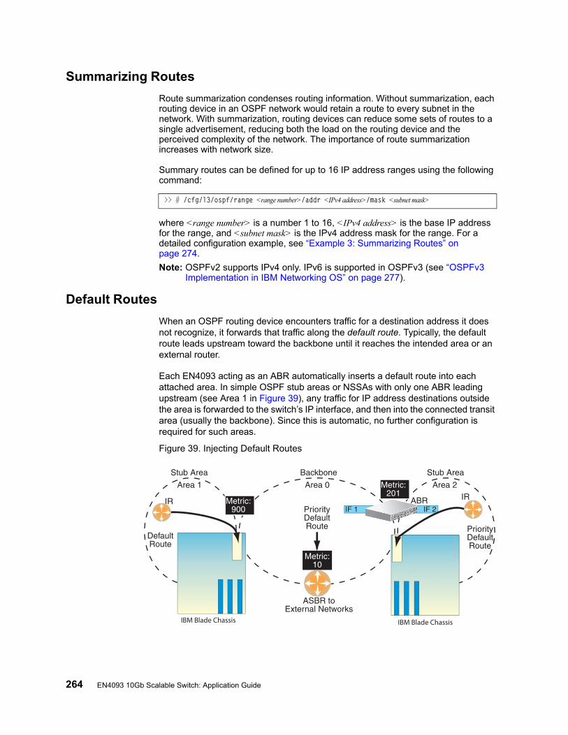
264 EN4093 10Gb Scalable Switch: Application Guide
Summarizing Routes
Route summarization condenses routing information. Without summarization, each routing device in an OSPF network would retain a route to every subnet in the network. With summarization, routing devices can reduce some sets of routes to a single advertisement, reducing both the load on the routing device and the perceived complexity of the network. The importance of route summarization increases with network size.
Summary routes can be defined for up to 16 IP address ranges using the following command:
where <range number> is a number 1 to 16, <IPv4 address> is the base IP address for the range, and <subnet mask> is the IPv4 address mask for the range. For a detailed configuration example, see “Example 3: Summarizing Routes” on page 274.
Note: OSPFv2 supports IPv4 only. IPv6 is supported in OSPFv3 (see “OSPFv3 Implementation in IBM Networking OS” on page 277).
Default Routes
When an OSPF routing device encounters traffic for a destination address it does not recognize, it forwards that traffic along the default route. Typically, the default route leads upstream toward the backbone until it reaches the intended area or an external router.
Each EN4093 acting as an ABR automatically inserts a default route into each attached area. In simple OSPF stub areas or NSSAs with only one ABR leading upstream (see Area 1 in Figure 39), any traffic for IP address destinations outside the area is forwarded to the switch’s IP interface, and then into the connected transit area (usually the backbone). Since this is automatic, no further configuration is required for such areas.
Figure 39. Injecting Default Routes
>> # /cfg/l3/ospf/range <range number>/addr <IPv4 address>/mask <subnet mask>
IBM Blade Chassis IBM Blade Chassis
© Copyright IBM Corp. 2012 Chapter 22: OSPF 265
If the switch is in a transit area and has a configured default gateway, it can inject a default route into rest of the OSPF domain. Use the following command to configure the switch to inject OSPF default routes:
In the command above, <metric value> sets the priority for choosing this switch for default route. The value none sets no default and 1 sets the highest priority for default route. Metric type determines the method for influencing routing decisions for external routes.
When the switch is configured to inject a default route, an AS-external LSA with link state ID 0.0.0.0 is propagated throughout the OSPF routing domain. This LSA is sent with the configured metric value and metric type.
The OSPF default route configuration can be removed with the command:
Virtual Links
Usually, all areas in an OSPF AS are physically connected to the backbone. In some cases where this is not possible, you can use a virtual link. Virtual links are created to connect one area to the backbone through another non-backbone area (see Figure 37 on page 257).
The area which contains a virtual link must be a transit area and have full routing information. Virtual links cannot be configured inside a stub area or NSSA. The area type must be defined as transit using the following command:
The virtual link must be configured on the routing devices at each endpoint of the virtual link, though they may traverse multiple routing devices. To configure a EN4093 as one endpoint of a virtual link, use the following command:
where <link number> is a value between 1 and 3, <area index> is the OSPF area index of the transit area, and <router ID> is the IP address of the virtual neighbor (nbr), the routing device at the target endpoint. Another router ID is needed when configuring a virtual link in the other direction. To provide the EN4093 with a router ID, see the following section, Router ID.
For a detailed configuration example on Virtual Links, see “Example 2: Virtual Links” on page 271.
>> # /cfg/l3/ospf/default <metric value> <metric type (1 or 2)>
>> # /cfg/l3/ospf/default none
>> # /cfg/l3/ospf/aindex <area index>/type transit
>> # /cfg/l3/ospf/virt <link number>/aindex <area index>/nbr <router ID>
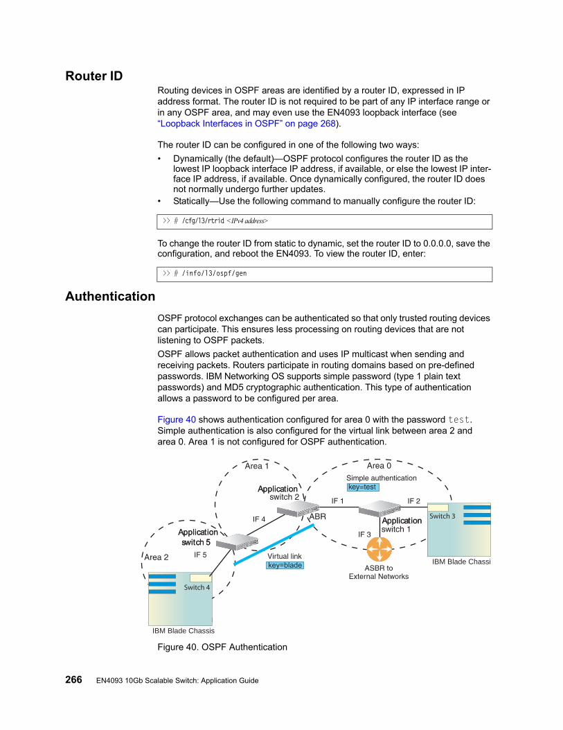
266 EN4093 10Gb Scalable Switch: Application Guide
Router IDRouting devices in OSPF areas are identified by a router ID, expressed in IP address format. The router ID is not required to be part of any IP interface range or in any OSPF area, and may even use the EN4093 loopback interface (see “Loopback Interfaces in OSPF” on page 268).
The router ID can be configured in one of the following two ways:
• Dynamically (the default)—OSPF protocol configures the router ID as the lowest IP loopback interface IP address, if available, or else the lowest IP inter-face IP address, if available. Once dynamically configured, the router ID does not normally undergo further updates.
• Statically—Use the following command to manually configure the router ID:
To change the router ID from static to dynamic, set the router ID to 0.0.0.0, save the configuration, and reboot the EN4093. To view the router ID, enter:
Authentication
OSPF protocol exchanges can be authenticated so that only trusted routing devices can participate. This ensures less processing on routing devices that are not listening to OSPF packets.
OSPF allows packet authentication and uses IP multicast when sending and receiving packets. Routers participate in routing domains based on pre-defined passwords. IBM Networking OS supports simple password (type 1 plain text passwords) and MD5 cryptographic authentication. This type of authentication allows a password to be configured per area.
Figure 40 shows authentication configured for area 0 with the password test. Simple authentication is also configured for the virtual link between area 2 and area 0. Area 1 is not configured for OSPF authentication.
Figure 40. OSPF Authentication
>> # /cfg/l3/rtrid <IPv4 address>
>> # /info/l3/ospf/gen
IBM Blade Chassis
IBM Blade Chassis
ApplicationApplication
ApplicationApplication
Application switch 5Application switch 5
key=blade
Switch 4
Switch 3
© Copyright IBM Corp. 2012 Chapter 22: OSPF 267
Configuring Plain Text OSPF Passwords
To configure plain text OSPF passwords as shown in Figure 40 use the following commands:
1. Enable OSPF authentication for Area 0 on switches 1, 2, and 3.
2. Configure a simple text password up to eight characters for each OSPF IP interface in Area 0 on switches 1, 2, and 3.
3. Enable OSPF authentication for Area 2 on switch 4.
4. Configure a simple text password up to eight characters for the virtual link between Area 2 and Area 0 on switches 2 and 4.
Configuring MD5 Authentication
Use the following commands to configure MD5 authentication on the switches shown in Figure 40:
1. Enable OSPF MD5 authentication for Area 0 on switches 1, 2, and 3.
2. Configure MD5 key ID for Area 0 on switches 1, 2, and 3.
3. Assign MD5 key ID to OSPF interfaces on switches 1, 2, and 3.
4. Enable OSPF MD5 authentication for Area 2 on switch 4.
5. Configure MD5 key for the virtual link between Area 2 and Area 0 on switch 2 and switch 4.
>> # /cfg/l3/ospf/aindex 0/auth password (Turn on password authentication)
>> # /cfg/l3/ospf/if 1/key test>> OSPF Interface 1 # ../if 2/key test>> OSPF Interface 2 # ../if 3/key test
>> # /cfg/l3/ospf/aindex 2/auth password (Turn on password authentication)
>> # /cfg/l3/ospf/virt 1/key blade
>> # /cfg/l3/ospf/aindex 0/auth md5 (Turn on MD5 authentication)
>> # /cfg/l3/ospf/md5key 1/key test
>> # /cfg/l3/ospf/if 1/mdkey 1>> OSPF Interface 1 # ../if 2/mdkey 1>> OSPF Interface 2 # ../if 3/mdkey 1
>> # /cfg/l3/ospf/aindex 2/auth md5
>> # /cfg/l3/ospf/md5key 2/key blade
268 EN4093 10Gb Scalable Switch: Application Guide
6. Assign MD5 key ID to OSPF virtual link on switches 2 and 4.
Host Routes for Load Balancing
IBM Networking OS implementation of OSPF includes host routes. Host routes are used for advertising network device IP addresses to external networks, accomplishing the following goals:
• ABR Load Sharing
As a form of load balancing, host routes can be used for dividing OSPF traffic among multiple ABRs. To accomplish this, each switch provides identical services but advertises a host route for a different IP address to the external network. If each IP address serves a different and equal portion of the external world, incoming traffic from the upstream router should be split evenly among ABRs.
• ABR Failover
Complementing ABR load sharing, identical host routes can be configured on each ABR. These host routes can be given different costs so that a different ABR is selected as the preferred route for each server and the others are available as backups for failover purposes.
• Equal Cost Multipath (ECMP)
With equal cost multipath, a router potentially has several available next hops towards any given destination. ECMP allows separate routes to be calculated for each IP Type of Service. All paths of equal cost to a given destination are calculated, and the next hops for all equal-cost paths are inserted into the routing table.
If redundant routes via multiple routing processes (such as OSPF, RIP, BGP, or static routes) exist on your network, the switch defaults to the OSPF-derived route.
Loopback Interfaces in OSPF
Because loopback interfaces are always available on the switch, loopback interfaces may present an advantage when used as the router ID.
If dynamic router ID selection is used (see “Router ID” on page 266), loopback interfaces can be used to force router ID selection. If a loopback interface is configured, its IP address is automatically selected as the router ID, even if other IP interfaces have lower IP addresses. If more than one loopback interface is configured, the lowest loopback interface IP address is selected.
Loopback interfaces can be advertised into the OSPF domain by specifying an OSPF host route with the loopback interface IP address.
OSPF Features Not Supported in This Release
The following OSPF features are not supported in this release:
• Summarizing external routes
• Filtering OSPF routes
• Using OSPF to forward multicast routes
• Configuring OSPF on non-broadcast multi-access networks (such as frame relay, X.25, or ATM)
>> # /cfg/l3/ospf/virt 1/mdkey 2
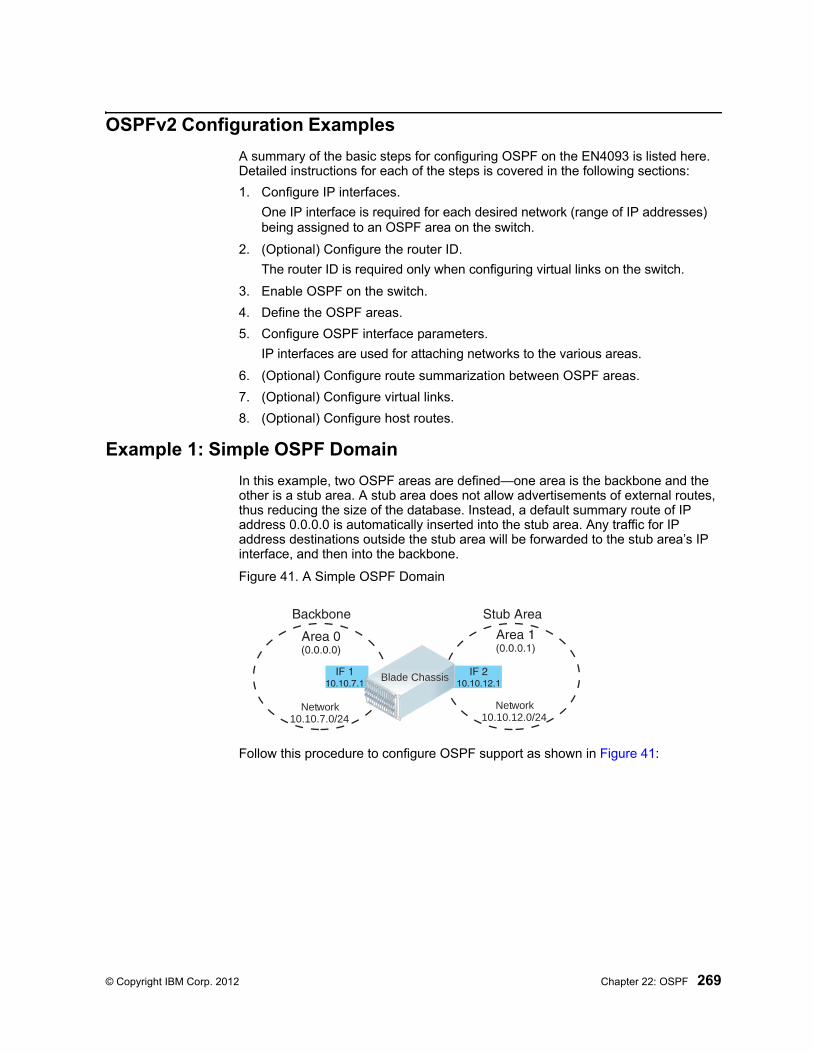
© Copyright IBM Corp. 2012 Chapter 22: OSPF 269
OSPFv2 Configuration Examples
A summary of the basic steps for configuring OSPF on the EN4093 is listed here. Detailed instructions for each of the steps is covered in the following sections:
1. Configure IP interfaces.
One IP interface is required for each desired network (range of IP addresses) being assigned to an OSPF area on the switch.
2. (Optional) Configure the router ID.
The router ID is required only when configuring virtual links on the switch.
3. Enable OSPF on the switch.
4. Define the OSPF areas.
5. Configure OSPF interface parameters.
IP interfaces are used for attaching networks to the various areas.
6. (Optional) Configure route summarization between OSPF areas.
7. (Optional) Configure virtual links.
8. (Optional) Configure host routes.
Example 1: Simple OSPF Domain
In this example, two OSPF areas are defined—one area is the backbone and the other is a stub area. A stub area does not allow advertisements of external routes, thus reducing the size of the database. Instead, a default summary route of IP address 0.0.0.0 is automatically inserted into the stub area. Any traffic for IP address destinations outside the stub area will be forwarded to the stub area’s IP interface, and then into the backbone.
Figure 41. A Simple OSPF Domain
Follow this procedure to configure OSPF support as shown in Figure 41:
BladeCenter
Blade ChassisBlade Chassis
Network10.10.12.0/2410.10.7.0/24
Network
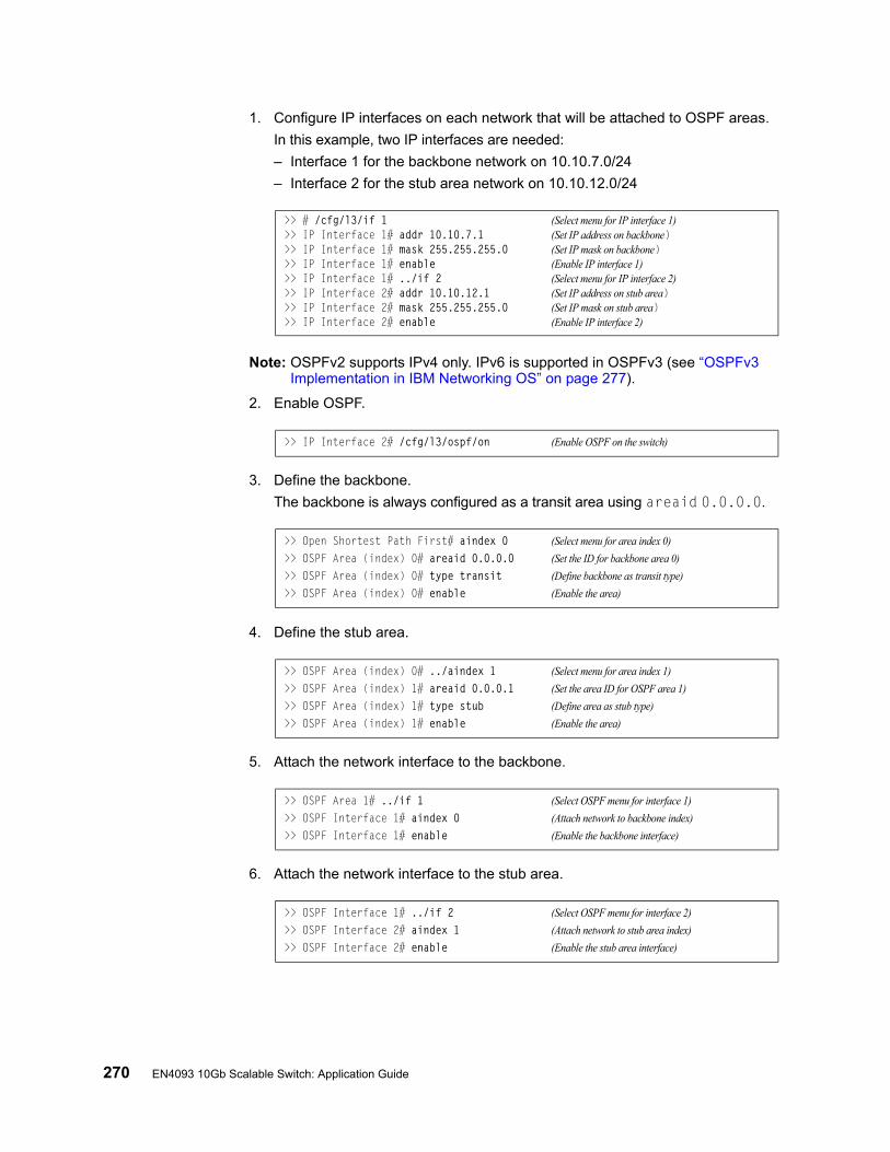
270 EN4093 10Gb Scalable Switch: Application Guide
1. Configure IP interfaces on each network that will be attached to OSPF areas.
In this example, two IP interfaces are needed:
– Interface 1 for the backbone network on 10.10.7.0/24
– Interface 2 for the stub area network on 10.10.12.0/24
Note: OSPFv2 supports IPv4 only. IPv6 is supported in OSPFv3 (see “OSPFv3 Implementation in IBM Networking OS” on page 277).
2. Enable OSPF.
3. Define the backbone.
The backbone is always configured as a transit area using areaid 0.0.0.0.
4. Define the stub area.
5. Attach the network interface to the backbone.
6. Attach the network interface to the stub area.
>> # /cfg/l3/if 1 (Select menu for IP interface 1)>> IP Interface 1# addr 10.10.7.1 (Set IP address on backbone)>> IP Interface 1# mask 255.255.255.0 (Set IP mask on backbone)>> IP Interface 1# enable (Enable IP interface 1)>> IP Interface 1# ../if 2 (Select menu for IP interface 2)>> IP Interface 2# addr 10.10.12.1 (Set IP address on stub area)>> IP Interface 2# mask 255.255.255.0 (Set IP mask on stub area)>> IP Interface 2# enable (Enable IP interface 2)
>> IP Interface 2# /cfg/l3/ospf/on (Enable OSPF on the switch)
>> Open Shortest Path First# aindex 0 (Select menu for area index 0)
>> OSPF Area (index) 0# areaid 0.0.0.0 (Set the ID for backbone area 0)
>> OSPF Area (index) 0# type transit (Define backbone as transit type)
>> OSPF Area (index) 0# enable (Enable the area)
>> OSPF Area (index) 0# ../aindex 1 (Select menu for area index 1)
>> OSPF Area (index) 1# areaid 0.0.0.1 (Set the area ID for OSPF area 1)
>> OSPF Area (index) 1# type stub (Define area as stub type)
>> OSPF Area (index) 1# enable (Enable the area)
>> OSPF Area 1# ../if 1 (Select OSPF menu for interface 1)
>> OSPF Interface 1# aindex 0 (Attach network to backbone index)
>> OSPF Interface 1# enable (Enable the backbone interface)
>> OSPF Interface 1# ../if 2 (Select OSPF menu for interface 2)
>> OSPF Interface 2# aindex 1 (Attach network to stub area index)
>> OSPF Interface 2# enable (Enable the stub area interface)
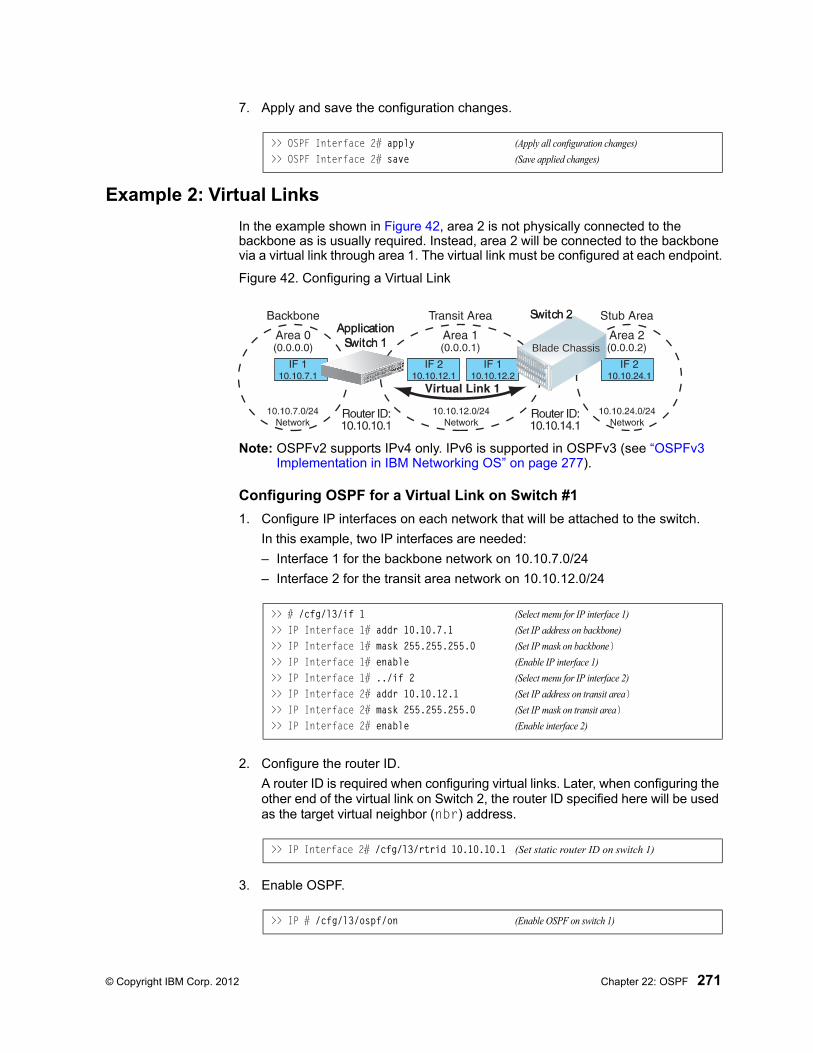
© Copyright IBM Corp. 2012 Chapter 22: OSPF 271
7. Apply and save the configuration changes.
Example 2: Virtual Links
In the example shown in Figure 42, area 2 is not physically connected to the backbone as is usually required. Instead, area 2 will be connected to the backbone via a virtual link through area 1. The virtual link must be configured at each endpoint.
Figure 42. Configuring a Virtual Link
Note: OSPFv2 supports IPv4 only. IPv6 is supported in OSPFv3 (see “OSPFv3 Implementation in IBM Networking OS” on page 277).
Configuring OSPF for a Virtual Link on Switch #1
1. Configure IP interfaces on each network that will be attached to the switch.
In this example, two IP interfaces are needed:
– Interface 1 for the backbone network on 10.10.7.0/24
– Interface 2 for the transit area network on 10.10.12.0/24
2. Configure the router ID.
A router ID is required when configuring virtual links. Later, when configuring the other end of the virtual link on Switch 2, the router ID specified here will be used as the target virtual neighbor (nbr) address.
3. Enable OSPF.
>> OSPF Interface 2# apply (Apply all configuration changes)
>> OSPF Interface 2# save (Save applied changes)
Blade ChassisBlade Chassis
Application Switch 1Application Switch 1
Switch 2Switch 2
>> # /cfg/l3/if 1 (Select menu for IP interface 1)
>> IP Interface 1# addr 10.10.7.1 (Set IP address on backbone)
>> IP Interface 1# mask 255.255.255.0 (Set IP mask on backbone)>> IP Interface 1# enable (Enable IP interface 1)
>> IP Interface 1# ../if 2 (Select menu for IP interface 2)
>> IP Interface 2# addr 10.10.12.1 (Set IP address on transit area)>> IP Interface 2# mask 255.255.255.0 (Set IP mask on transit area)>> IP Interface 2# enable (Enable interface 2)
>> IP Interface 2# /cfg/l3/rtrid 10.10.10.1 (Set static router ID on switch 1)
>> IP # /cfg/l3/ospf/on (Enable OSPF on switch 1)
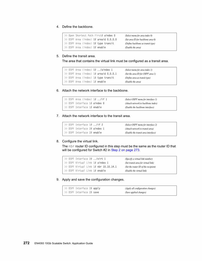
272 EN4093 10Gb Scalable Switch: Application Guide
4. Define the backbone.
5. Define the transit area.
The area that contains the virtual link must be configured as a transit area.
6. Attach the network interface to the backbone.
7. Attach the network interface to the transit area.
8. Configure the virtual link.
The nbr router ID configured in this step must be the same as the router ID that will be configured for Switch #2 in Step 2 on page 273.
9. Apply and save the configuration changes.
>> Open Shortest Path First# aindex 0 (Select menu for area index 0)
>> OSPF Area (index) 0# areaid 0.0.0.0 (Set area ID for backbone area 0)
>> OSPF Area (index) 0# type transit (Define backbone as transit type)
>> OSPF Area (index) 0# enable (Enable the area)
>> OSPF Area (index) 0# ../aindex 1 (Select menu for area index 1)
>> OSPF Area (index) 1# areaid 0.0.0.1 (Set the area ID for OSPF area 1)
>> OSPF Area (index) 1# type transit (Define area as transit type)
>> OSPF Area (index) 1# enable (Enable the area)
>> OSPF Area (index) 1# ../if 1 (Select OSPF menu for interface 1)
>> OSPF Interface 1# aindex 0 (Attach network to backbone index)
>> OSPF Interface 1# enable (Enable the backbone interface)
>> OSPF Interface 1# ../if 2 (Select OSPF menu for interface 2)
>> OSPF Interface 2# aindex 1 (Attach network to transit area)
>> OSPF Interface 2# enable (Enable the transit area interface)
>> OSPF Interface 2# ../virt 1 (Specify a virtual link number)
>> OSPF Virtual Link 1# aindex 1 (Set transit area for virtual link)
>> OSPF Virtual Link 1# nbr 10.10.14.1 (Set the router ID of the recipient)
>> OSPF Virtual Link 1# enable (Enable the virtual link)
>> OSPF Interface 2# apply (Apply all configuration changes)
>> OSPF Interface 2# save (Save applied changes)
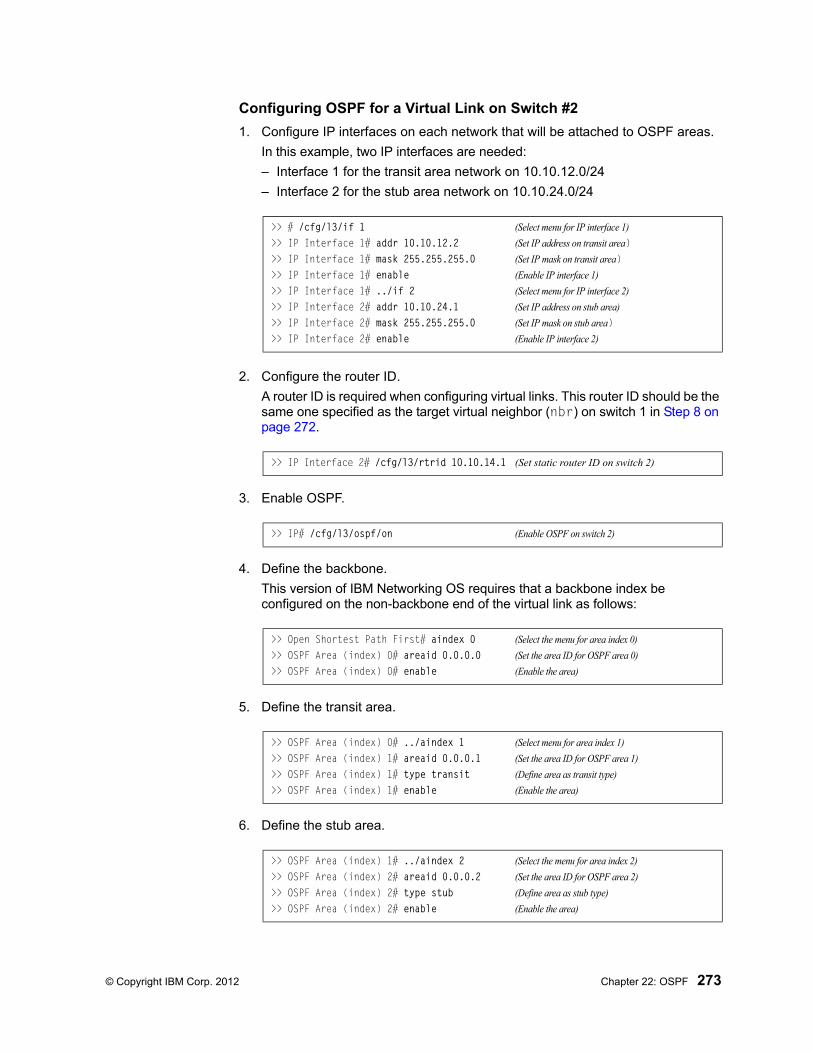
© Copyright IBM Corp. 2012 Chapter 22: OSPF 273
Configuring OSPF for a Virtual Link on Switch #2
1. Configure IP interfaces on each network that will be attached to OSPF areas.
In this example, two IP interfaces are needed:
– Interface 1 for the transit area network on 10.10.12.0/24
– Interface 2 for the stub area network on 10.10.24.0/24
2. Configure the router ID.
A router ID is required when configuring virtual links. This router ID should be the same one specified as the target virtual neighbor (nbr) on switch 1 in Step 8 on page 272.
3. Enable OSPF.
4. Define the backbone.
This version of IBM Networking OS requires that a backbone index be configured on the non-backbone end of the virtual link as follows:
5. Define the transit area.
6. Define the stub area.
>> # /cfg/l3/if 1 (Select menu for IP interface 1)
>> IP Interface 1# addr 10.10.12.2 (Set IP address on transit area)>> IP Interface 1# mask 255.255.255.0 (Set IP mask on transit area)>> IP Interface 1# enable (Enable IP interface 1)
>> IP Interface 1# ../if 2 (Select menu for IP interface 2)
>> IP Interface 2# addr 10.10.24.1 (Set IP address on stub area)
>> IP Interface 2# mask 255.255.255.0 (Set IP mask on stub area)>> IP Interface 2# enable (Enable IP interface 2)
>> IP Interface 2# /cfg/l3/rtrid 10.10.14.1 (Set static router ID on switch 2)
>> IP# /cfg/l3/ospf/on (Enable OSPF on switch 2)
>> Open Shortest Path First# aindex 0 (Select the menu for area index 0)
>> OSPF Area (index) 0# areaid 0.0.0.0 (Set the area ID for OSPF area 0)
>> OSPF Area (index) 0# enable (Enable the area)
>> OSPF Area (index) 0# ../aindex 1 (Select menu for area index 1)
>> OSPF Area (index) 1# areaid 0.0.0.1 (Set the area ID for OSPF area 1)
>> OSPF Area (index) 1# type transit (Define area as transit type)
>> OSPF Area (index) 1# enable (Enable the area)
>> OSPF Area (index) 1# ../aindex 2 (Select the menu for area index 2)
>> OSPF Area (index) 2# areaid 0.0.0.2 (Set the area ID for OSPF area 2)
>> OSPF Area (index) 2# type stub (Define area as stub type)
>> OSPF Area (index) 2# enable (Enable the area)
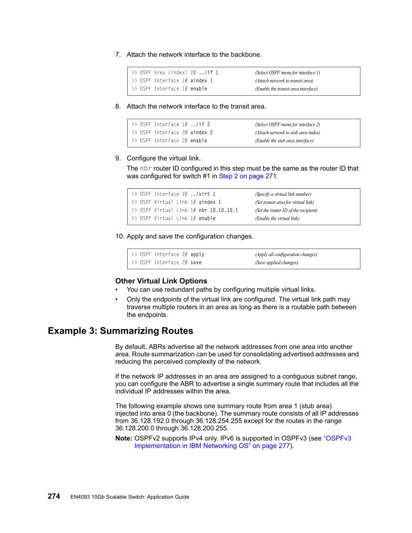
274 EN4093 10Gb Scalable Switch: Application Guide
7. Attach the network interface to the backbone.
8. Attach the network interface to the transit area.
9. Configure the virtual link.
The nbr router ID configured in this step must be the same as the router ID that was configured for switch #1 in Step 2 on page 271.
10. Apply and save the configuration changes.
Other Virtual Link Options• You can use redundant paths by configuring multiple virtual links.
• Only the endpoints of the virtual link are configured. The virtual link path may traverse multiple routers in an area as long as there is a routable path between the endpoints.
Example 3: Summarizing Routes
By default, ABRs advertise all the network addresses from one area into another area. Route summarization can be used for consolidating advertised addresses and reducing the perceived complexity of the network.
If the network IP addresses in an area are assigned to a contiguous subnet range, you can configure the ABR to advertise a single summary route that includes all the individual IP addresses within the area.
The following example shows one summary route from area 1 (stub area) injected into area 0 (the backbone). The summary route consists of all IP addresses from 36.128.192.0 through 36.128.254.255 except for the routes in the range 36.128.200.0 through 36.128.200.255.
Note: OSPFv2 supports IPv4 only. IPv6 is supported in OSPFv3 (see “OSPFv3 Implementation in IBM Networking OS” on page 277).
>> OSPF Area (index) 2# ../if 1 (Select OSPF menu for interface 1)
>> OSPF Interface 1# aindex 1 (Attach network to transit area)
>> OSPF Interface 1# enable (Enable the transit area interface)
>> OSPF Interface 1# ../if 2 (Select OSPF menu for interface 2)
>> OSPF Interface 2# aindex 2 (Attach network to stub area index)
>> OSPF Interface 2# enable (Enable the stub area interface)
>> OSPF Interface 2# ../virt 1 (Specify a virtual link number)
>> OSPF Virtual Link 1# aindex 1 (Set transit area for virtual link)
>> OSPF Virtual Link 1# nbr 10.10.10.1 (Set the router ID of the recipient)
>> OSPF Virtual Link 1# enable (Enable the virtual link)
>> OSPF Interface 2# apply (Apply all configuration changes)
>> OSPF Interface 2# save (Save applied changes)

© Copyright IBM Corp. 2012 Chapter 22: OSPF 275
Figure 43. Summarizing Routes
Note: You can specify a range of addresses to prevent advertising by using the hide option. In this example, routes in the range 36.128.200.0 through 36.128.200.255 are kept private.
Follow this procedure to configure OSPF support as shown in Figure 43:
1. Configure IP interfaces for each network which will be attached to OSPF areas.
2. Enable OSPF.
3. Define the backbone.
4. Define the stub area.
5. Attach the network interface to the backbone.
Blade ChassisBlade Chassis
>> # /cfg/l3/if 1 (Select menu for IP interface 1)
>> IP Interface 1# addr 10.10.7.1 (Set IP address on backbone)
>> IP Interface 1# mask 255.255.255.0 (Set IP mask on backbone)>> IP Interface 1# ena (Enable IP interface 1)
>> IP Interface 1# ../if 2 (Select menu for IP interface 2)
>> IP Interface 2# addr 36.128.192.1 (Set IP address on stub area)
>> IP Interface 2# mask 255.255.192.0 (Set IP mask on stub area)>> IP Interface 2# ena (Enable IP interface 2)
>> IP Interface 2# /cfg/l3/ospf/on (Enable OSPF on the switch)
>> Open Shortest Path First# aindex 0 (Select menu for area index 0)
>> OSPF Area (index) 0# areaid 0.0.0.0 (Set the ID for backbone area 0)
>> OSPF Area (index) 0# type transit (Define backbone as transit type)
>> OSPF Area (index) 0# enable (Enable the area)
>> OSPF Area (index) 0# ../aindex 1 (Select menu for area index 1)
>> OSPF Area (index) 1# areaid 0.0.0.1 (Set the area ID for OSPF area 1)
>> OSPF Area (index) 1# type stub (Define area as stub type)
>> OSPF Area (index) 1# enable (Enable the area)
>> OSPF Area (index) 1# ../if 1 (Select OSPF menu for interface 1)
>> OSPF Interface 1# aindex 0 (Attach network to backbone index)
>> OSPF Interface 1# enable (Enable the backbone interface)
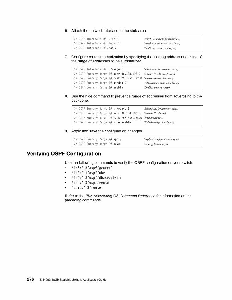
276 EN4093 10Gb Scalable Switch: Application Guide
6. Attach the network interface to the stub area.
7. Configure route summarization by specifying the starting address and mask of the range of addresses to be summarized.
8. Use the hide command to prevent a range of addresses from advertising to the backbone.
9. Apply and save the configuration changes.
Verifying OSPF Configuration
Use the following commands to verify the OSPF configuration on your switch:
• /info/l3/ospf/general• /info/l3/ospf/nbr• /info/l3/ospf/dbase/dbsum• /info/l3/ospf/route• /stats/l3/route
Refer to the IBM Networking OS Command Reference for information on the preceding commands.
>> OSPF Interface 1# ../if 2 (Select OSPF menu for interface 2)
>> OSPF Interface 2# aindex 1 (Attach network to stub area index)
>> OSPF Interface 2# enable (Enable the stub area interface)
>> OSPF Interface 2# ../range 1 (Select menu for summary range)
>> OSPF Summary Range 1# addr 36.128.192.0 (Set base IP address of range)
>> OSPF Summary Range 1# mask 255.255.192.0 (Set mask address for range)
>> OSPF Summary Range 1# aindex 0 (Add summary route to backbone)
>> OSPF Summary Range 1# enable (Enable summary range)
>> OSPF Summary Range 1# ../range 2 (Select menu for summary range)
>> OSPF Summary Range 2# addr 36.128.200.0 (Set base IP address)
>> OSPF Summary Range 2# mask 255.255.255.0 (Set mask address)
>> OSPF Summary Range 2# hide enable (Hide the range of addresses)
>> OSPF Summary Range 2# apply (Apply all configuration changes)
>> OSPF Summary Range 2# save (Save applied changes)

© Copyright IBM Corp. 2012 Chapter 22: OSPF 277
OSPFv3 Implementation in IBM Networking OS
OSPF version 3 is based on OSPF version 2, but has been modified to support IPv6 addressing. In most other ways, OSPFv3 is similar to OSPFv2: They both have the same packet types and interfaces, and both use the same mechanisms for neighbor discovery, adjacency formation, LSA flooding, aging, and so on. The administrator should be familiar with the OSPFv2 concepts covered in the preceding sections of this chapter before implementing the OSPFv3 differences as described in the following sections.
Although OSPFv2 and OSPFv3 are very similar, they represent independent features on the EN4093. They are configured separately, and both can run in parallel on the switch with no relation to one another, serving different IPv6 and IPv4 traffic, respectively.
OSPFv3 Differences from OSPFv2Note: When OSPFv3 is enabled, the OSPF backbone area (0.0.0.0) is created by
default and is always active.
OSPFv3 Requires IPv6 Interfaces
OSPFv3 is designed to support IPv6 addresses. This requires IPv6 interfaces to be configured on the switch and assigned to OSPF areas, in much the same way IPv4 interfaces are assigned to areas in OSPFv2. This is the primary configuration difference between OSPFv3 and OSPFv2.
See “Internet Protocol Version 6” on page 203 for configuring IPv6 interfaces.
OSPFv3 Uses Independent Command Paths
Though OSPFv3 and OSPFv2 are very similar, they are configured independently. They each have their own separate menus in the CLI, and their own command paths in the ISCLI. OSPFv3 base menus and command paths are located as follows:
• In the menu-based CLI
• In the ISCLI
>> # /cfg/l3/ospf3 (OSPFv3 config menu)>> # /info/l3/ospf3 (OSPFv3 information menu)>> # /stats/l3/ospf3 (OSPFv3 statistics menu)
EN 4093(config)# ipv6 router ospf (OSPFv3 router config mode)EN 4093(config-router-ospf3)# ?
EN 4093(config)# interface ip <Interface number> (Configure OSPFv3)EN 4093(config-ip-if)# ipv6 ospf ? (OSPFv3 interface config)
EN 4093# show ipv6 ospf ? (Show OSPFv3 information)

278 EN4093 10Gb Scalable Switch: Application Guide
OSPFv3 Identifies Neighbors by Router ID
Where OSPFv2 uses a mix of IPv4 interface addresses and Router IDs to identify neighbors, depending on their type, OSPFv3 configuration consistently uses a Router ID to identify all neighbors.
Although Router IDs are written in dotted decimal notation, and may even be based on IPv4 addresses from an original OSPFv2 network configuration, it is important to realize that Router IDs are not IP addresses in OSPFv3, and can be assigned independently of IP address space. However, maintaining Router IDs consistent with any legacy OSPFv2 IPv4 addressing allows for easier implementation of both protocols.
Other Internal Improvements
OSPFv3 has numerous improvements that increase the protocol efficiency in addition to supporting IPv6 addressing. These improvements change some of the behaviors in the OSPFv3 network and may affect topology consideration, but have little direct impact on configuration. For example:
• Addressing fields have been removed from Router and Network LSAs.
• Link-local flooding scope has been added, along with a Link LSA. This allows flooding information to relevant local neighbors without forwarded it beyond the local router.
• Flexible treatment of unknown LSA types to make integration of OSPFv3 easier.
OSPFv3 Limitations
IBM Networking OS 7.2 does not currently support the following OSPFv3 features:
• Multiple instances of OSPFv3 on one IPv6 link.
• Authentication of OSPFv3 packets via IPv6 Security (IPsec) for Virtual-Link.
OSPFv3 Configuration Example
The following example depicts the OSPFv3 equivalent configuration of “Example 3: Summarizing Routes” on page 274 for OSPFv2.
In this example, one summary route from area 1 (stub area) is injected into area 0 (the backbone). The summary route consists of all IP addresses for the 36.:0/32 portion of the 36::0/56 network except for the routes in the 36::0/8 range.
Figure 44. Summarizing Routes
Note: You can specify a range of addresses to prevent advertising by using the hide option. In this example, routes in the 36::0/8 range are kept private.
BLADE SwitchIF 310::1
IF 436::1
10::0/56Network
36::0/56Network
36::0/32( - 36::0/8)
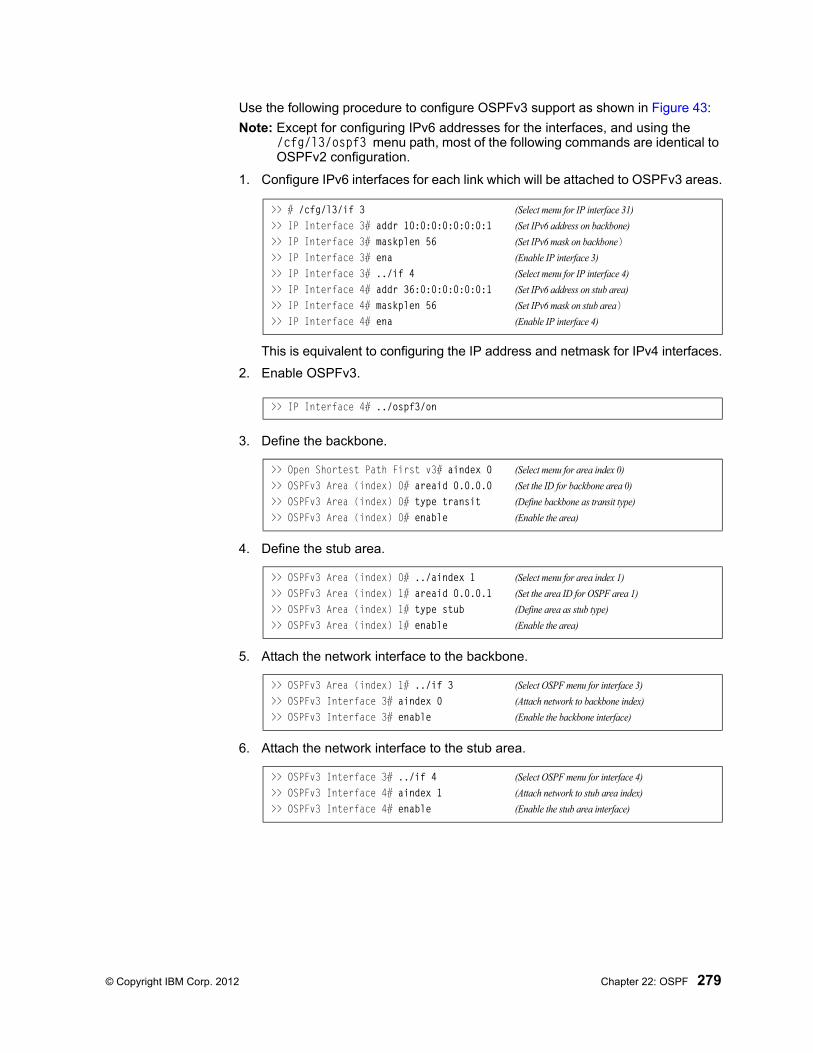
© Copyright IBM Corp. 2012 Chapter 22: OSPF 279
Use the following procedure to configure OSPFv3 support as shown in Figure 43:
Note: Except for configuring IPv6 addresses for the interfaces, and using the /cfg/l3/ospf3 menu path, most of the following commands are identical to OSPFv2 configuration.
1. Configure IPv6 interfaces for each link which will be attached to OSPFv3 areas.
This is equivalent to configuring the IP address and netmask for IPv4 interfaces.
2. Enable OSPFv3.
3. Define the backbone.
4. Define the stub area.
5. Attach the network interface to the backbone.
6. Attach the network interface to the stub area.
>> # /cfg/l3/if 3 (Select menu for IP interface 31)
>> IP Interface 3# addr 10:0:0:0:0:0:0:1 (Set IPv6 address on backbone)
>> IP Interface 3# maskplen 56 (Set IPv6 mask on backbone)>> IP Interface 3# ena (Enable IP interface 3)
>> IP Interface 3# ../if 4 (Select menu for IP interface 4)
>> IP Interface 4# addr 36:0:0:0:0:0:0:1 (Set IPv6 address on stub area)
>> IP Interface 4# maskplen 56 (Set IPv6 mask on stub area)>> IP Interface 4# ena (Enable IP interface 4)
>> IP Interface 4# ../ospf3/on
>> Open Shortest Path First v3# aindex 0 (Select menu for area index 0)
>> OSPFv3 Area (index) 0# areaid 0.0.0.0 (Set the ID for backbone area 0)
>> OSPFv3 Area (index) 0# type transit (Define backbone as transit type)
>> OSPFv3 Area (index) 0# enable (Enable the area)
>> OSPFv3 Area (index) 0# ../aindex 1 (Select menu for area index 1)
>> OSPFv3 Area (index) 1# areaid 0.0.0.1 (Set the area ID for OSPF area 1)
>> OSPFv3 Area (index) 1# type stub (Define area as stub type)
>> OSPFv3 Area (index) 1# enable (Enable the area)
>> OSPFv3 Area (index) 1# ../if 3 (Select OSPF menu for interface 3)
>> OSPFv3 Interface 3# aindex 0 (Attach network to backbone index)
>> OSPFv3 Interface 3# enable (Enable the backbone interface)
>> OSPFv3 Interface 3# ../if 4 (Select OSPF menu for interface 4)
>> OSPFv3 Interface 4# aindex 1 (Attach network to stub area index)
>> OSPFv3 Interface 4# enable (Enable the stub area interface)
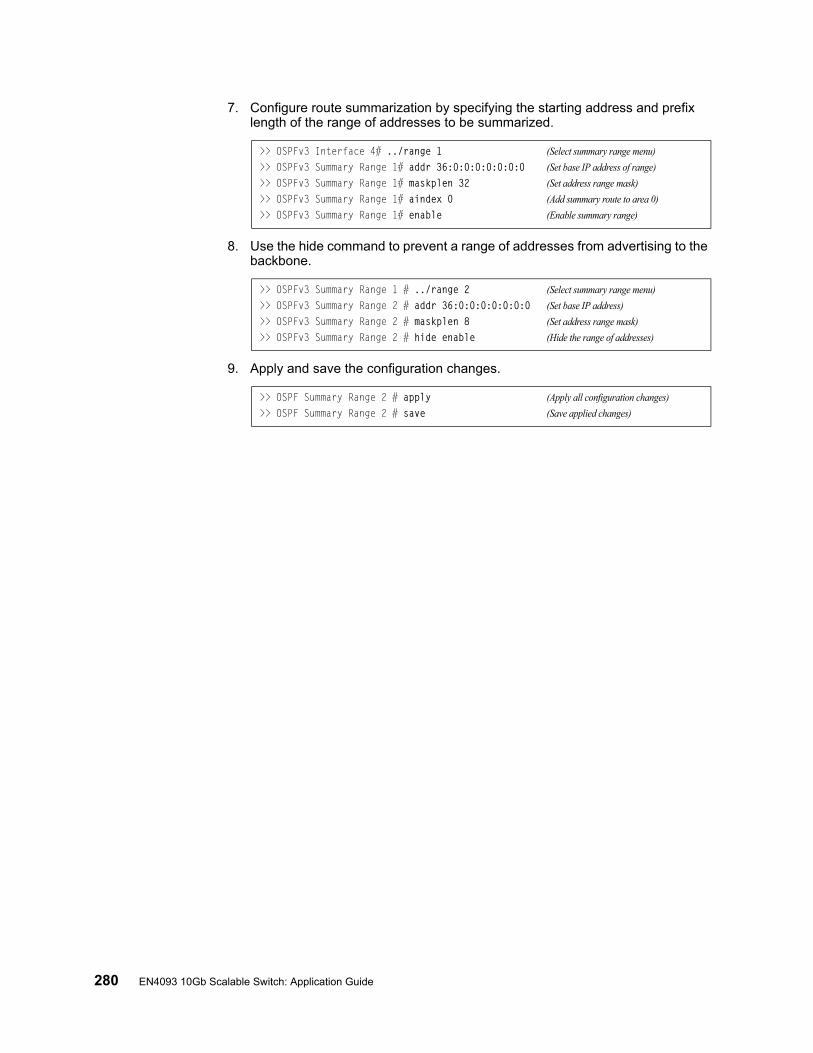
280 EN4093 10Gb Scalable Switch: Application Guide
7. Configure route summarization by specifying the starting address and prefix length of the range of addresses to be summarized.
8. Use the hide command to prevent a range of addresses from advertising to the backbone.
9. Apply and save the configuration changes.
>> OSPFv3 Interface 4# ../range 1 (Select summary range menu)
>> OSPFv3 Summary Range 1# addr 36:0:0:0:0:0:0:0 (Set base IP address of range)
>> OSPFv3 Summary Range 1# maskplen 32 (Set address range mask)
>> OSPFv3 Summary Range 1# aindex 0 (Add summary route to area 0)
>> OSPFv3 Summary Range 1# enable (Enable summary range)
>> OSPFv3 Summary Range 1 # ../range 2 (Select summary range menu)
>> OSPFv3 Summary Range 2 # addr 36:0:0:0:0:0:0:0 (Set base IP address)
>> OSPFv3 Summary Range 2 # maskplen 8 (Set address range mask)
>> OSPFv3 Summary Range 2 # hide enable (Hide the range of addresses)
>> OSPF Summary Range 2 # apply (Apply all configuration changes)
>> OSPF Summary Range 2 # save (Save applied changes)
© Copyright IBM Corp. 2012 281
Chapter 23. Protocol Independent Multicast
IBM Networking OS supports Protocol Independent Multicast (PIM) in Sparse Mode (PIM-SM) and Dense Mode (PIM-DM).
Note: IBM Networking OS 7.2 does not support IPv6 for PIM.
The following sections discuss PIM support for the EN4093 10Gb Scalable Switch:
• “PIM Overview” on page 281• “Supported PIM Modes and Features” on page 282• “Basic PIM Settings” on page 282• “Additional Sparse Mode Settings” on page 285• “Using PIM with Other Features” on page 286• “PIM Configuration Examples” on page 287
PIM Overview
PIM is designed for efficiently routing multicast traffic across one or more IPv4 domains. This has benefits for application such as IP television, collaboration, education, and software delivery, where a single source must deliver content (a multicast) to a group of receivers that span both wide-area and inter-domain networks.
Instead of sending a separate copy of content to each receiver, a multicast derives efficiency by sending only a single copy of content toward its intended receivers. This single copy only becomes duplicated when it reaches the target domain that includes multiple receivers, or when it reaches a necessary bifurcation point leading to different receiver domains.
PIM is used by multicast source stations, client receivers, and intermediary routers and switches, to build and maintain efficient multicast routing trees. PIM is protocol independent; It collects routing information using the existing unicast routing functions underlying the IPv4 network, but does not rely on any particular unicast protocol. For PIM to function, a Layer 3 routing protocol (such as BGP, OSPF, RIP, or static routes) must first be configured on the switch.
PIM-SM is a reverse-path routing mechanism. Client receiver stations advertise their willingness to join a multicast group. The local routing and switching devices collect multicast routing information and forward the request toward the station that will provide the multicast content. When the join requests reach the sending station, the multicast data is sent toward the receivers, flowing in the opposite direction of the original join requests.
Some routing and switching devices perform special PIM-SM functions. Within each receiver domain, one router is elected as the Designated Router (DR) for handling multicasts for the domain. DRs forward information to a similar device, the Rendezvous Point (RP), which holds the root tree for the particular multicast group.
Receiver join requests as well as sender multicast content initially converge at the RP, which generates and distributes multicast routing data for the DRs along the delivery path. As the multicast content flows, DRs use the routing tree information obtained from the RP to optimize the paths both to and from send and receive stations, bypassing the RP for the remainder of content transactions if a more efficient route is available.
282 EN4093 10Gb Scalable Switch: Application Guide
DRs continue to share routing information with the RP, modifying the multicast routing tree when new receivers join, or pruning the tree when all the receivers in any particular domain are no longer part of the multicast group.
Supported PIM Modes and Features
For each interface attached to a PIM network component, PIM can be configured to operate either in PIM Sparse Mode (PIM-SM) or PIM Dense Mode (PIM-DM).
• PIM-SM is used in networks where multicast senders and receivers comprise a relatively small (sparse) portion of the overall network. PIM-SM uses a more complex process than PIM-DM for collecting and optimizing multicast routes, but minimizes impact on other IP services and is more commonly used.
• PIM-DM is used where multicast devices are a relatively large (dense) portion of the network, with very frequent (or constant) multicast traffic. PIM-DM requires less configuration on the switch than PIM-SM, but uses broadcasts that can consume more bandwidth in establishing and optimizing routes.
The following PIM modes and features are not currently supported in IBM Networking OS 7.2:
• Hybrid Sparse-Dense Mode (PIM-SM/DM). Sparse Mode and Dense Mode may be configured on separate IP interfaces on the switch, but are not currently sup-ported simultaneously on the same IP interface.
• PIM Source-Specific Multicast (PIM-SSM)• Anycast RP• PIM RP filters• Only configuration via the switch ISCLI is supported. PIM configuration is cur-
rently not available using the menu-based CLI, the BBI, or via SNMP.
Basic PIM Settings
To use PIM the following is required:
• The PIM feature must be enabled globally on the switch.• PIM network components and PIM modes must be defined.• IP interfaces must be configured for each PIM component.• PIM neighbor filters may be defined (optional).• If PIM-SM is used, define additional parameters:
– Rendezvous Point
– Designated Router preferences (optional)
– Bootstrap Router preferences (optional)
Each of these tasks is covered in the following sections.
Note: PIM can be configured through the ISCLI only. PIM configuration and information are not available using the menu-based CLI, the BBI, or via SNMP.
Globally Enabling or Disabling the PIM Feature
By default, PIM is disabled on the switch. PIM can be globally enabled or disabled using the following ISCLI commands:
EN 4093(config)# [no] ip pim enable
© Copyright IBM Corp. 2012 Chapter 23: Protocol Independent Multicast 283
Defining a PIM Network Component
The EN4093 can be attached to a maximum of two independent PIM network components. Each component represents a different PIM network, and can be defined for either PIM-SM or PIM-DM operation. Basic PIM component configuration is performed using the following commands:
The sparse option will place the component in Sparse Mode (PIM-SM). The dense option will place the component in Dense Mode (PIM-DM). By default, PIM component 1 is configured for Sparse Mode. PIM component 2 is unconfigured by default.
Note: A component using PIM-SM must also be configured with a dynamic or static Rendezvous Point (see “Specifying the Rendezvous Point” on page 285).
Defining an IP Interface for PIM Use
Each network attached to an IP interface on the switch may be assigned one of the available PIM components. The same PIM component can be assigned to multiple IP interfaces. The interfaces may belong to the same VLAN, but each interface can belong to only one VLAN.
To define an IP interface for use with PIM, first configured the interface with an IPv4 address and VLAN as follows:
Note: The PIM feature currently supports only one VLAN for each IP interface. Configurations where different interfaces on different VLANs share IP addresses are not supported.
Next, PIM must be enabled on the interface, and the PIM network component ID must be specified:
By default, PIM component 1 is automatically assigned when PIM is enabled on the IP interface.
Note: While PIM is enabled on the interface, the interface VLAN cannot be changed. To change the VLAN, first disable PIM on the interface.
EN 4093(config)# ip pim component <1-2>EN 4093(config-ip-pim-comp)# mode {sparse|dense}EN 4093(config-ip-pim-comp)# exit
EN 4093(config)# interface ip <Interface number>EN 4093(config-ip-if)# ip address <IPv4 address> <IPv4 mask>EN 4093(config-ip-if)# vlan <VLAN number>EN 4093(config-ip-if)# enable
EN 4093(config-ip-if)# ip pim enableEN 4093(config-ip-if)# ip pim component-id <1-2>EN 4093(config-ip-if)# exit
284 EN4093 10Gb Scalable Switch: Application Guide
PIM Neighbor Filters
The EN4093 accepts connection to up to 8 PIM interfaces. By default, the switch accepts all PIM neighbors attached to the PIM-enabled interfaces, up to the maximum number. Once the maximum is reached, the switch will deny further PIM neighbors.
To ensure that only the appropriate PIM neighbors are accepted by the switch, the administrator can use PIM neighbor filters to specify which PIM neighbors may be accepted or denied on a per-interface basis.
To turn PIM neighbor filtering on or off for a particular IP interface, use the following commands:
When filtering is enabled, all PIM neighbor requests on the specified IP interface will be denied by default. To allow a specific PIM neighbor, use the following command:
To remove a PIM neighbor from the accepted list, use the following command.
You can view configured PIM neighbor filters globally or for a specific IP interface using the following commands:
EN 4093(config)# interface ip <Interface number>EN 4093(config-ip-if)# [no] ip pim neighbor-filter
EN 4093(config-ip-if)# ip pim neighbor-addr <neighbor IPv4 address> allow
EN 4093(config-ip-if)# ip pim neighbor-addr <neighbor IPv4 address> denyEN 4093(config-ip-if)# exit
EN 4093(config)# show ip pim neighbor-filtersEN 4093(config)# show ip pim interface <Interface number> neighbor-filters
© Copyright IBM Corp. 2012 Chapter 23: Protocol Independent Multicast 285
Additional Sparse Mode Settings
Specifying the Rendezvous Point
Using PIM-SM, at least one PIM-capable router must be a candidate for use as a Rendezvous Point (RP) for any given multicast group. If desired, the EN4093 can act as an RP candidate. To assign a configured switch IP interface as a candidate, use the following procedure.
1. Select the PIM component that will represent the RP candidate:
2. Configure the IPv4 address of the switch interface which will be advertised as a candidate RP for the specified multicast group:
The switch interface will participate in the election of the RP that occurs on the Bootstrap Router, or BSR (see “Specifying a Bootstrap Router” on page 286).
Alternately, if no election is desired, the switch can provide a static RP, specified using the following command:
3. If using dynamic RP candidates, configure the amount of time that the elected interface will remain the RP for the group before a re-election is performed:
Influencing the Designated Router Selection
Using PIM-SM, All PIM-enabled IP interfaces are considered as potential Designate Routers (DR) for their domain. By default, the interface with the highest IP address on the domain is selected. However, if an interface is configured with a DR priority value, it overrides the IP address selection process. If more than one interface on a domain is configured with a DR priority, the one with the highest number is selected.
Use the following commands to configure the DR priority value (Interface IP mode):
Note: A value of 0 (zero) specifies that the EN4093 will not act as the DR. This setting requires the EN4093 to be connected to a peer that has a DR priority setting of 1 or higher in order to ensure that a DR will be present in the network.
EN 4093(config)# ip pim component <1-2>
EN 4093(config-ip-pim-comp)# rp-candidate rp-address <group address> <group address mask> <candidate IPv4 address>
EN 4093(config-ip-pim-comp)# rp-static rp-address <group address> <group address mask> <static RP IPv4 address>
EN 4093(config-ip-pim-comp)# rp-candidate holdtime <0-255>EN 4093(config-ip-pim-comp)# exit
EN 4093(config)# interface ip <Interface number>EN 4093(config-ip-if)# ip pim dr-priority <value (0-4294967294)>EN 4093(config-ip-if)# exit
286 EN4093 10Gb Scalable Switch: Application Guide
Specifying a Bootstrap Router
Using PIM-SM, a Bootstrap Router (BSR) is a PIM-capable router that hosts the election of the RP from available candidate routers. For each PIM-enabled IP interface, the administrator can set the preference level for which the local interface becomes the BSR:
A value of 255 highly prefers the local interface as a BSR. A value of 0 indicates that the local interface should not act as a BSR.
Using PIM with Other Features
PIM with ACLs or VMAPs
If using ACLs or VMAPs, be sure to permit traffic for local hosts and routers.
PIM with IGMP
If using IGMP (see “Internet Group Management Protocol” on page 227):
• IGMP static joins can be configured with a PIM-SM or PIM-DM multicast group IPv4 address. Using the ISCLI:
Using the CLI
• IGMP Query is disabled by default. If IGMP Querier is needed with PIM, be sure to enable the IGMP Query feature globally, as well as on each VLAN where it is needed.
• If the switch is connected to multicast receivers and/or hosts, be sure to enable IGMP snooping globally, as well as on each VLAN where PIM receivers are attached.
EN 4093(config)# interface ip <Interface number>EN 4093(config-ip-if)# ip pim cbsr-preference <0 to 255>EN 4093(config-ip-if)# exit
EN 4093(config)# ip mroute <multicast group IPv4 address> <VLAN> <port>
>> # /cfg/l3/mroute <multicast group IPv4 address> <VLAN> <port>

© Copyright IBM Corp. 2012 Chapter 23: Protocol Independent Multicast 287
PIM Configuration Examples
Example 1: PIM-SM with Dynamic RP
This example configures PIM Sparse Mode for one IP interface, with the switch acting as a candidate for dynamic Rendezvous Point (RP) selection.
1. Globally enable the PIM feature:
2. Configure a PIM network component with dynamic RP settings, and set it for PIM Sparse Mode:
Where 225.1.0.0 is the multicast group base IP address, 255.255.0.0 is the multicast group address mask, and 10.10.1.1 is the switch RP candidate address.
Note: Because, Sparse Mode is set by default for PIM component 1, the mode command is needed only if the mode has been previously changed.
3. Define an IP interface for use with PIM:
The IP interface represents the PIM network being connected to the switch. The IPv4 addresses in the defined range must not be included in another IP interface on the switch under a different VLAN.
4. Enable PIM on the IP interface and assign the PIM component:
Note: Because, PIM component 1 is assigned to the interface by default, the component-id command is needed only if the setting has been previously changed.
5. Set the Bootstrap Router (BSR) preference:
EN 4093(config)# ip pim enable
EN 4093(config)# ip pim component 1EN 4093(config-ip-pim-comp)# mode sparseEN 4093(config-ip-pim-comp)# rp-candidate rp-address 225.1.0.0 255.255.0.0
10.10.1.1EN 4093(config-ip-pim-comp)# exit
EN 4093(config)# interface ip 111EN 4093(config-ip-if)# ip address 10.10.1.1 255.255.255.255EN 4093(config-ip-if)# vlan 11EN 4093(config-ip-if)# enable
EN 4093(config-ip-if)# ip pim enableEN 4093(config-ip-if)# ip pim component-id 1
EN 4093(config-ip-if)# ip pim cbsr-preference 135EN 4093(config-ip-if)# exit

288 EN4093 10Gb Scalable Switch: Application Guide
Example 2: PIM-SM with Static RP
The following commands can be used to modify the prior example configuration to use a static RP:
Where 225.1.0.0 255.255.0.0 is the multicast group base address and mask, and 10.10.1.1 is the static RP address.
Note: The same static RP address should be configured for all switches in the group.
EN 4093(config)# ip pim static-rp enableEN 4093(config)# ip pim component 1EN 4093(config-ip-pim-comp)# rp-static rp-address 225.1.0.0 255.255.0.0 10.10.1.1EN 4093(config-ip-pim-comp)# exit
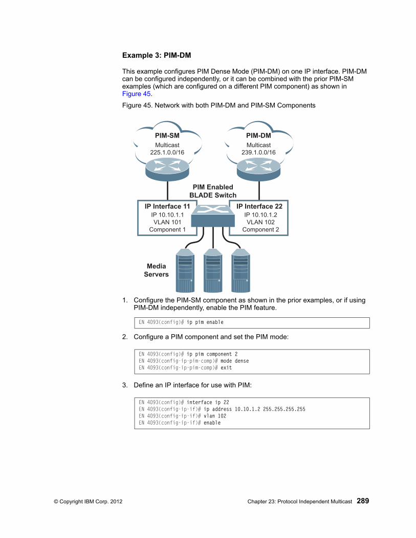
© Copyright IBM Corp. 2012 Chapter 23: Protocol Independent Multicast 289
Example 3: PIM-DM
This example configures PIM Dense Mode (PIM-DM) on one IP interface. PIM-DM can be configured independently, or it can be combined with the prior PIM-SM examples (which are configured on a different PIM component) as shown in Figure 45.
Figure 45. Network with both PIM-DM and PIM-SM Components
1. Configure the PIM-SM component as shown in the prior examples, or if using PIM-DM independently, enable the PIM feature.
2. Configure a PIM component and set the PIM mode:
3. Define an IP interface for use with PIM:
PIM-SM
MediaServers
PIM-DMMulticast
225.1.0.0/16
Multicast
239.1.0.0/16
IP 10.10.1.1
VLAN 101
Component 1
IP 10.10.1.2
VLAN 102
Component 2
IP Interface 11 IP Interface 22
PIM EnabledBLADE Switch
EN 4093(config)# ip pim enable
EN 4093(config)# ip pim component 2EN 4093(config-ip-pim-comp)# mode denseEN 4093(config-ip-pim-comp)# exit
EN 4093(config)# interface ip 22EN 4093(config-ip-if)# ip address 10.10.1.2 255.255.255.255EN 4093(config-ip-if)# vlan 102EN 4093(config-ip-if)# enable

290 EN4093 10Gb Scalable Switch: Application Guide
4. Enable PIM on the IP interface and assign the PIM component:
Note: For PIM Dense Mode, the DR, RP, and BSR settings do not apply.
EN 4093(config-ip-if)# ip pim enableEN 4093(config-ip-if)# ip pim component-id 2EN 4093(config-ip-if)# exit
© Copyright IBM Corp. 2012 291
Part 6: High Availability Fundamentals
Internet traffic consists of myriad services and applications which use the Internet Protocol (IP) for data delivery. However, IP is not optimized for all the various applications. High Availability goes beyond IP and makes intelligent switching decisions to provide redundant network configurations.

292 EN4093 10Gb Scalable Switch: Application Guide

© Copyright IBM Corp. 2012 293
Chapter 24. Basic Redundancy
IBM Networking OS 7.2 includes various features for providing basic link or device redundancy:
• “Trunking for Link Redundancy” on page 293
• “Hot Links” on page 294
Trunking for Link Redundancy
Multiple switch ports can be combined together to form robust, high-bandwidth trunks to other devices. Since trunks are comprised of multiple physical links, the trunk group is inherently fault tolerant. As long as one connection between the switches is available, the trunk remains active.
In Figure 46, four ports are trunked together between the switch and the enterprise routing device. Connectivity is maintained as long as one of the links remain active. The links to the server are also trunked, allowing the secondary NIC to take over in the event that the primary NIC link fails.
Figure 46. Trunking Ports for Link Redundancy
For more information on trunking, see “Ports and Trunking” on page 95.
Trunk Trunk
Server
NIC 1
NIC 2Internet
EnterpriseRouting Switch
BladeSwitch
294 EN4093 10Gb Scalable Switch: Application Guide
Hot Links
For network topologies that require Spanning Tree to be turned off, Hot Links provides basic link redundancy with fast recovery.
Hot Links consists of up to 25 triggers. A trigger consists of a pair of layer 2 interfaces, each containing an individual port, trunk, or LACP adminkey. One interface is the Master, and the other is a Backup. While the Master interface is set to the active state and forwards traffic, the Backup interface is set to the standby state and blocks traffic until the Master interface fails. If the Master interface fails, the Backup interface is set to active and forwards traffic. Once the Master interface is restored, it transitions to the standby state and blocks traffic until the Backup interface fails.
You may select a physical port, static trunk, or an LACP adminkey as a Hot Link interface. Only external uplink ports can be members of a Hot Links trigger interface.
Forward Delay
The Forward Delay timer allows Hot Links to monitor the Master and Backup interfaces for link stability before selecting one interface to transition to the active state. Before the transition occurs, the interface must maintain a stable link for the duration of the Forward Delay interval.
For example, if you set the Forward delay timer to 10 seconds (/cfg/l2/hotlink/trigger <x>/fdelay 10), the switch will select an interface to become active only if a link remained stable for the duration of the Forward Delay period. If the link is unstable, the Forward Delay period starts again.
Preemption
You can configure the Master interface to resume the active state whenever it becomes available. With Hot Links preemption enabled (/cfg/l2/hotlink/trigger <x>/preempt ena), the Master interface transitions to the active state immediately upon recovery. The Backup interface immediately transitions to the standby state. If Forward Delay is enabled, the transition occurs when an interface has maintained link stability for the duration of the Forward Delay period.
FDB Update
Use the FDB update option to notify other devices on the network about updates to the Forwarding Database (FDB). When you enable FDB update (/cfg/l2/hotlink/sndfdb ena), the switch sends multicasts of addresses in the forwarding database (FDB) over the active interface, so that other devices on the network can learn the new path. The Hot Links FBD update option uses the station update rate (/cfg/l2/hotlink/sndrate) to determine the rate at which to send FDB packets.
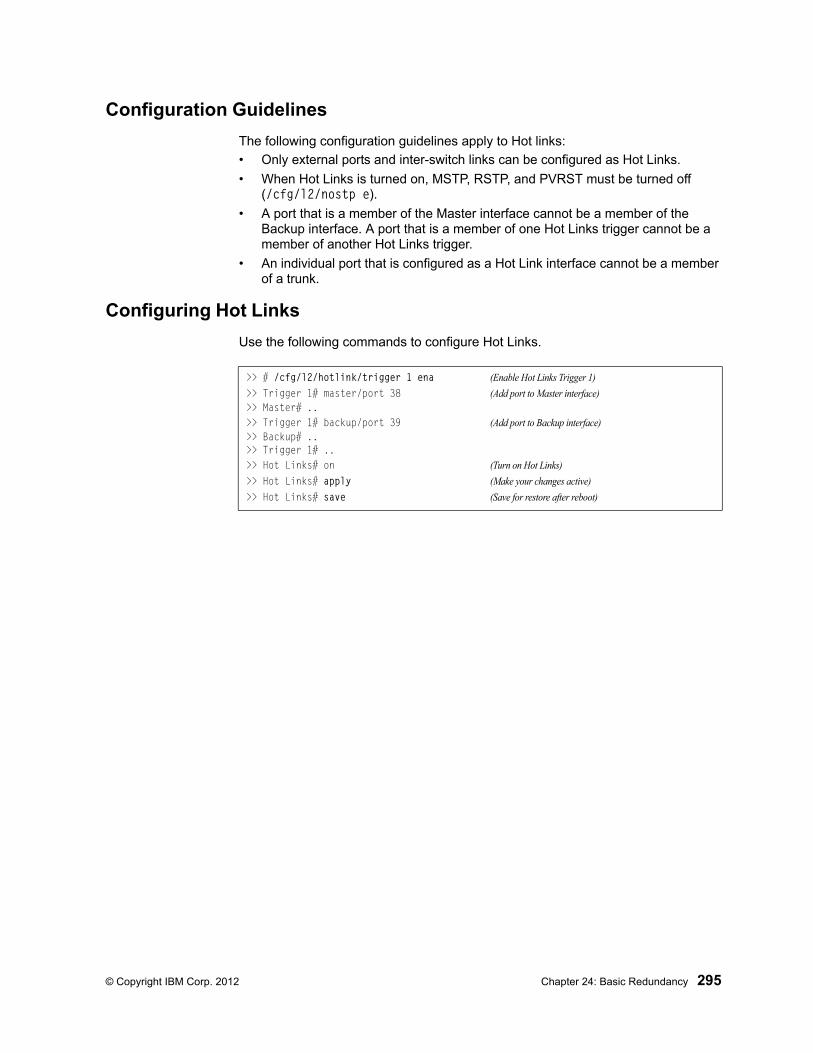
© Copyright IBM Corp. 2012 Chapter 24: Basic Redundancy 295
Configuration Guidelines
The following configuration guidelines apply to Hot links:
• Only external ports and inter-switch links can be configured as Hot Links.
• When Hot Links is turned on, MSTP, RSTP, and PVRST must be turned off (/cfg/l2/nostp e).
• A port that is a member of the Master interface cannot be a member of the Backup interface. A port that is a member of one Hot Links trigger cannot be a member of another Hot Links trigger.
• An individual port that is configured as a Hot Link interface cannot be a member of a trunk.
Configuring Hot Links
Use the following commands to configure Hot Links.
>> # /cfg/l2/hotlink/trigger 1 ena (Enable Hot Links Trigger 1)
>> Trigger 1# master/port 38 (Add port to Master interface)>> Master# ..>> Trigger 1# backup/port 39 (Add port to Backup interface)>> Backup# ..>> Trigger 1# ..>> Hot Links# on (Turn on Hot Links)
>> Hot Links# apply (Make your changes active)
>> Hot Links# save (Save for restore after reboot)

296 EN4093 10Gb Scalable Switch: Application Guide
© Copyright IBM Corp. 2012 297
Chapter 25. Layer 2 Failover
The primary application for Layer 2 Failover is to support Network Adapter Teaming. With Network Adapter Teaming, all the NICs on each server share the same IP address, and are configured into a team. One NIC is the primary link, and the other is a standby link. For more details, refer to the documentation for your Ethernet adapter.
Note: Only two links per server blade can be used for Layer 2 Trunk Failover (one primary and one backup). Network Adapter Teaming allows only one backup NIC for each server blade.
Auto Monitoring Trunk Links
Layer 2 Failover can be enabled on any trunk group in the EN4093, including LACP trunks. Trunks can be added to failover trigger groups. Then, if some specified number of trigger links fail, the switch disables all the internal ports in the switch (unless VLAN Monitor is turned on). When the internal ports are disabled, it causes the NIC team on the affected server blades to failover from the primary to the backup NIC. This process is called a failover event.
When the appropriate number of links in a trigger group return to service, the switch enables the internal ports. This causes the NIC team on the affected server blades to fail back to the primary switch (unless Auto-Fallback is disabled on the NIC team). The backup switch processes traffic until the primary switch’s internal links come up, which can take up to five seconds.
VLAN Monitor
The VLAN Monitor allows Layer 2 Failover to discern different VLANs. With VLAN Monitor turned on:
• If enough links in a trigger fail (see “Setting the Failover Limit” on page 299), the switch disables all internal ports that reside in the same VLAN membership as the trunk(s) in the trigger.
• When enough links in the trigger return to service, the switch enables the internal ports that reside in the same VLAN membership as the trunk(s) in the trigger.
If you turn off the VLAN Monitor (/cfg/l2/failovr/vlan/off), only one failover trigger is allowed. When a link failure occurs on the trigger, the switch disables all internal server-blade ports.
Auto Monitor Configurations
Figure 47 is a simple example of Layer 2 Failover. One EN4093 is the primary, and the other is used as a backup. In this example, all external ports on the primary switch belong to a single trunk group, with Layer 2 Failover enabled, and Failover Limit set to 2. If two or fewer links in trigger 1 remain active, the switch temporarily disables all internal server-blade ports that reside in VLAN 1. This action causes a failover event on Server 1 and Server 2.
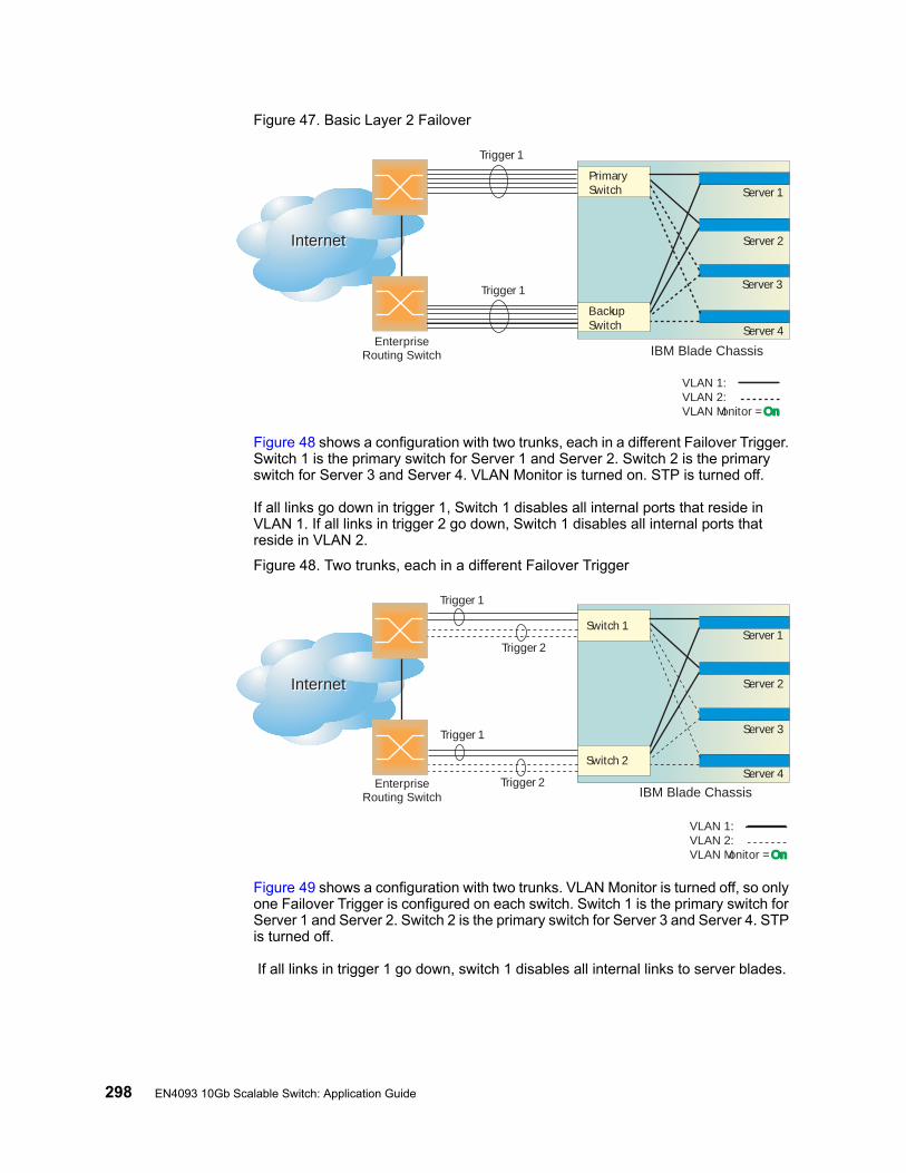
298 EN4093 10Gb Scalable Switch: Application Guide
Figure 47. Basic Layer 2 Failover
Figure 48 shows a configuration with two trunks, each in a different Failover Trigger. Switch 1 is the primary switch for Server 1 and Server 2. Switch 2 is the primary switch for Server 3 and Server 4. VLAN Monitor is turned on. STP is turned off.
If all links go down in trigger 1, Switch 1 disables all internal ports that reside in VLAN 1. If all links in trigger 2 go down, Switch 1 disables all internal ports that reside in VLAN 2.
Figure 48. Two trunks, each in a different Failover Trigger
Figure 49 shows a configuration with two trunks. VLAN Monitor is turned off, so only one Failover Trigger is configured on each switch. Switch 1 is the primary switch for Server 1 and Server 2. Switch 2 is the primary switch for Server 3 and Server 4. STP is turned off.
If all links in trigger 1 go down, switch 1 disables all internal links to server blades.
InternetInternet
EnterpriseRouting Switch
PrimarySwitch
BackupSwitch
Trigger 1
IBM Blade Chassis
Server 1
Server 3
Server 2
Server 4
Trigger 1
VLAN 1:VLAN 2:VLAN Monitor = OnOn
InternetInternet
EnterpriseRouting Switch
Switch 1
Switch 2
Trigger 2
Trigger 1
Trigger 1
Trigger 2IBM Blade Chassis
VLAN 1:VLAN 2:VLAN Monitor = OnOn
Server 1
Server 3
Server 2
Server 4
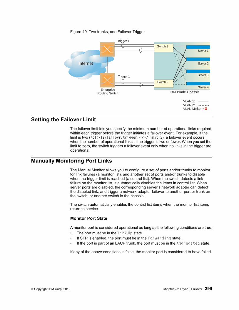
© Copyright IBM Corp. 2012 Chapter 25: Layer 2 Failover 299
Figure 49. Two trunks, one Failover Trigger
Setting the Failover Limit
The failover limit lets you specify the minimum number of operational links required within each trigger before the trigger initiates a failover event. For example, if the limit is two (/cfg/l2/failovr/trigger <x>/limit 2), a failover event occurs when the number of operational links in the trigger is two or fewer. When you set the limit to zero, the switch triggers a failover event only when no links in the trigger are operational.
Manually Monitoring Port Links
The Manual Monitor allows you to configure a set of ports and/or trunks to monitor for link failures (a monitor list), and another set of ports and/or trunks to disable when the trigger limit is reached (a control list). When the switch detects a link failure on the monitor list, it automatically disables the items in control list. When server ports are disabled, the corresponding server’s network adapter can detect the disabled link, and trigger a network-adapter failover to another port or trunk on the switch, or another switch in the chassis.
The switch automatically enables the control list items when the monitor list items return to service.
Monitor Port State
A monitor port is considered operational as long as the following conditions are true:
• The port must be in the Link Up state.• If STP is enabled, the port must be in the Forwarding state.• If the port is part of an LACP trunk, the port must be in the Aggregated state.
If any of the above conditions is false, the monitor port is considered to have failed.
InternetInternet
EnterpriseRouting Switch
Switch 1
Switch 2
Trigger 1
Trigger 1
IBM Blade Chassis
Server 1
VLAN 1:VLAN 2: VLAN Monitor = OO
Server 3
Server 2
Server 4
300 EN4093 10Gb Scalable Switch: Application Guide
Control Port State
A control port is considered Operational if the monitor trigger is up. As long as the trigger is up, the port is considered operational from a teaming perspective, even if the port itself is actually in the Down state, Blocking state (if STP is enabled on the port), or Not Aggregated state (if part of an LACP trunk).
A control port is considered to have failed only if the monitor trigger is in the Down state.
To view the state of any port, use one of the following commands:
L2 Failover with Other Features
L2 Failover works together with Link Aggregation Control Protocol (LACP) and with Spanning Tree Protocol (STP), as described in the next sections.
LACP
Link Aggregation Control Protocol allows the switch to form dynamic trunks. You can use the admin key to add up to two LACP trunks to a failover trigger using automatic monitoring. When you add an admin key to a trigger (/cfg/l2/failovr/trigger <x>/amon/addkey), any LACP trunk with that admin key becomes a member of the trigger.
Spanning Tree Protocol
If Spanning Tree Protocol (STP) is enabled on the ports in a failover trigger, the switch monitors the port STP state rather than the link state. A port failure results when STP is not in a Forwarding state (such as Learning, Discarding, or No Link). The switch automatically disables the appropriate internal ports, based on the VLAN monitor.
When the switch determines that ports in the trigger are in STP Forwarding state, then it automatically enables the appropriate internal ports, based on the VLAN monitor. The switch fails back to normal operation.
>> # /info/link (View port link status)>> # /info/l2/stp (View port STP status)>> # /info/l2/lacp/dump (View port LACP status)
© Copyright IBM Corp. 2012 Chapter 25: Layer 2 Failover 301
Configuration Guidelines
This section provides important information about configuring Layer 2 Failover.
Note: Auto Monitor and Manual Monitor are mutually exclusive. They cannot both be configured on the switch.
Auto Monitor Guidelines
• Any specific failover trigger may monitor static trunks only or LACP trunks only, but not both.
• All external ports in all static or LACP trunks added to any specific failover trigger must belong to the same VLAN.
• A maximum of two LACP keys can be added per trigger.
• When VLAN Monitor is on, the following additional guidelines apply:
– All external ports in all static or LACP trunks added to a specific failover trigger must belong to the same VLAN and have the same PVID.
– Different triggers are not permitted to operate on the same VLAN.
– Different triggers are not permitted to operate on the same internal port.
– For each port in each trunk in a specific failover trigger, the trigger will monitor the STP state on only the default PVID.
Manual Monitor Guidelines
• A Manual Monitor can monitor only external ports.
• Any specific failover trigger can monitor external ports only, static trunks only, or LACP trunks only. The different types cannot be combined in the same trigger.
• A maximum of two LACP keys can be added per trigger.
• Port membership for different triggers should not overlap. Any specific port should be a member of only one trigger.
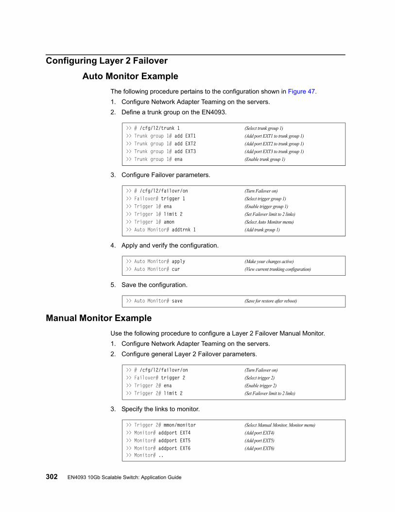
302 EN4093 10Gb Scalable Switch: Application Guide
Configuring Layer 2 Failover
Auto Monitor Example
The following procedure pertains to the configuration shown in Figure 47.
1. Configure Network Adapter Teaming on the servers.
2. Define a trunk group on the EN4093.
3. Configure Failover parameters.
4. Apply and verify the configuration.
5. Save the configuration.
Manual Monitor Example
Use the following procedure to configure a Layer 2 Failover Manual Monitor.
1. Configure Network Adapter Teaming on the servers.
2. Configure general Layer 2 Failover parameters.
3. Specify the links to monitor.
>> # /cfg/l2/trunk 1 (Select trunk group 1)
>> Trunk group 1# add EXT1 (Add port EXT1 to trunk group 1)
>> Trunk group 1# add EXT2 (Add port EXT2 to trunk group 1)
>> Trunk group 1# add EXT3 (Add port EXT3 to trunk group 1)
>> Trunk group 1# ena (Enable trunk group 1)
>> # /cfg/l2/failovr/on (Turn Failover on)
>> Failover# trigger 1 (Select trigger group 1)
>> Trigger 1# ena (Enable trigger group 1)
>> Trigger 1# limit 2 (Set Failover limit to 2 links)
>> Trigger 1# amon (Select Auto Monitor menu)
>> Auto Monitor# addtrnk 1 (Add trunk group 1)
>> Auto Monitor# apply (Make your changes active)
>> Auto Monitor# cur (View current trunking configuration)
>> Auto Monitor# save (Save for restore after reboot)
>> # /cfg/l2/failovr/on (Turn Failover on)
>> Failover# trigger 2 (Select trigger 2)
>> Trigger 2# ena (Enable trigger 2)
>> Trigger 2# limit 2 (Set Failover limit to 2 links)
>> Trigger 2# mmon/monitor (Select Manual Monitor, Monitor menu)
>> Monitor# addport EXT4 (Add port EXT4)
>> Monitor# addport EXT5 (Add port EXT5)
>> Monitor# addport EXT6 (Add port EXT6)>> Monitor# ..
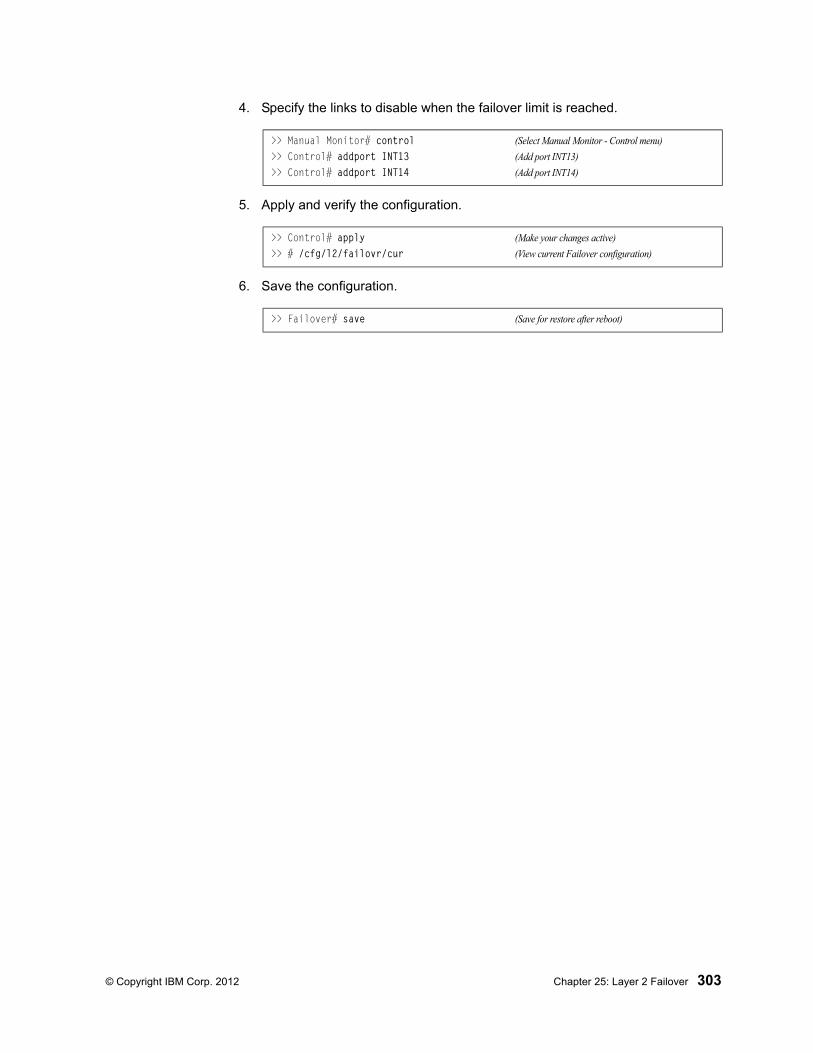
© Copyright IBM Corp. 2012 Chapter 25: Layer 2 Failover 303
4. Specify the links to disable when the failover limit is reached.
5. Apply and verify the configuration.
6. Save the configuration.
>> Manual Monitor# control (Select Manual Monitor - Control menu)
>> Control# addport INT13 (Add port INT13)
>> Control# addport INT14 (Add port INT14)
>> Control# apply (Make your changes active)
>> # /cfg/l2/failovr/cur (View current Failover configuration)
>> Failover# save (Save for restore after reboot)

304 EN4093 10Gb Scalable Switch: Application Guide
© Copyright IBM Corp. 2012 305
Chapter 26. Virtual Router Redundancy Protocol
The EN4093 10Gb Scalable Switch (EN4093) supports IPv4 high-availability network topologies through an enhanced implementation of the Virtual Router Redundancy Protocol (VRRP).
Note: IBM Networking OS 7.2 does not support IPv6 for VRRP.
The following topics are discussed in this chapter:
• “VRRP Overview” on page 305. This section discusses VRRP operation and IBM Networking OS redundancy configurations.
• “Failover Methods” on page 308. This section describes the three modes of high availability.
• “IBM Networking OS Extensions to VRRP” on page 311. This section describes VRRP enhancements implemented in IBM Networking OS.
• “Virtual Router Deployment Considerations” on page 312. This section describes issues to consider when deploying virtual routers.
• “High Availability Configurations” on page 313. This section discusses the more useful and easily deployed redundant configurations.
– “Active-Active Configuration” on page 313
– “Hot-Standby Configuration” on page 318
VRRP Overview
In a high-availability network topology, no device can create a single point-of-failure for the network or force a single point-of-failure to any other part of the network. This means that your network will remain in service despite the failure of any single device. To achieve this usually requires redundancy for all vital network components.
VRRP enables redundant router configurations within a LAN, providing alternate router paths for a host to eliminate single points-of-failure within a network. Each participating VRRP-capable routing device is configured with the same virtual router IPv4 address and ID number. One of the virtual routers is elected as the master, based on a number of priority criteria, and assumes control of the shared virtual router IPv4 address. If the master fails, one of the backup virtual routers will take control of the virtual router IPv4 address and actively process traffic addressed to it.
With VRRP, Virtual Interface Routers (VIR) allow two VRRP routers to share an IP interface across the routers. VIRs provide a single Destination IPv4 (DIP) address for upstream routers to reach various servers, and provide a virtual default Gateway for the server blades.
306 EN4093 10Gb Scalable Switch: Application Guide
VRRP Components
Each physical router running VRRP is known as a VRRP router.
Virtual Router
Two or more VRRP routers can be configured to form a virtual router (RFC 2338). Each VRRP router may participate in one or more virtual routers. Each virtual router consists of a user-configured virtual router identifier (VRID) and an IPv4 address.
Virtual Router MAC Address
The VRID is used to build the virtual router MAC Address. The five highest-order octets of the virtual router MAC Address are the standard MAC prefix (00-00-5E-00-01) defined in RFC 2338. The VRID is used to form the lowest-order octet.
Owners and Renters
Only one of the VRRP routers in a virtual router may be configured as the IPv4 address owner. This router has the virtual router’s IPv4 address as its real interface address. This router responds to packets addressed to the virtual router’s IPv4 address for ICMP pings, TCP connections, and so on.
There is no requirement for any VRRP router to be the IPv4 address owner. Most VRRP installations choose not to implement an IPv4 address owner. For the purposes of this chapter, VRRP routers that are not the IPv4 address owner are called renters.
Master and Backup Virtual Router
Within each virtual router, one VRRP router is selected to be the virtual router master. See “Selecting the Master VRRP Router” on page 307 for an explanation of the selection process.
Note: If the IPv4 address owner is available, it will always become the virtual router master.
The virtual router master forwards packets sent to the virtual router. It also responds to Address Resolution Protocol (ARP) requests sent to the virtual router's IPv4 address. Finally, the virtual router master sends out periodic advertisements to let other VRRP routers know it is alive and its priority.
Within a virtual router, the VRRP routers not selected to be the master are known as virtual router backups. Should the virtual router master fail, one of the virtual router backups becomes the master and assumes its responsibilities.
Virtual Interface Router
At Layer 3, a Virtual Interface Router (VIR) allows two VRRP routers to share an IP interface across the routers. VIRs provide a single Destination IPv4 (DIP) address for upstream routers to reach various destination networks, and provide a virtual default Gateway.

© Copyright IBM Corp. 2012 Chapter 26: Virtual Router Redundancy Protocol 307
Note: Every VIR must be assigned to an IP interface, and every IP interface must be assigned to a VLAN. If no port in a VLAN has link up, the IP interface of that VLAN is down, and if the IP interface of a VIR is down, that VIR goes into INIT state.
VRRP Operation
Only the virtual router master responds to ARP requests. Therefore, the upstream routers only forward packets destined to the master. The master also responds to ICMP ping requests. The backup does not forward any traffic, nor does it respond to ARP requests.
If the master is not available, the backup becomes the master and takes over responsibility for packet forwarding and responding to ARP requests.
Selecting the Master VRRP Router
Each VRRP router is configured with a priority between 1–254. A bidding process determines which VRRP router is or becomes the master—the VRRP router with the highest priority.
The master periodically sends advertisements to an IPv4 multicast address. As long as the backups receive these advertisements, they remain in the backup state. If a backup does not receive an advertisement for three advertisement intervals, it initiates a bidding process to determine which VRRP router has the highest priority and takes over as master.
If, at any time, a backup determines that it has higher priority than the current master does, it can preempt the master and become the master itself, unless configured not to do so. In preemption, the backup assumes the role of master and begins to send its own advertisements. The current master sees that the backup has higher priority and will stop functioning as the master.
A backup router can stop receiving advertisements for one of two reasons—the master can be down, or all communications links between the master and the backup can be down. If the master has failed, it is clearly desirable for the backup (or one of the backups, if there is more than one) to become the master.
Note: If the master is healthy but communication between the master and the backup has failed, there will then be two masters within the virtual router. To prevent this from happening, configure redundant links to be used between the switches that form a virtual router.
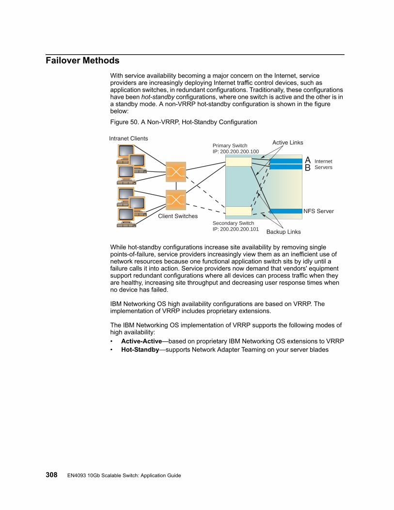
308 EN4093 10Gb Scalable Switch: Application Guide
Failover Methods
With service availability becoming a major concern on the Internet, service providers are increasingly deploying Internet traffic control devices, such as application switches, in redundant configurations. Traditionally, these configurations have been hot-standby configurations, where one switch is active and the other is in a standby mode. A non-VRRP hot-standby configuration is shown in the figure below:
Figure 50. A Non-VRRP, Hot-Standby Configuration
While hot-standby configurations increase site availability by removing single points-of-failure, service providers increasingly view them as an inefficient use of network resources because one functional application switch sits by idly until a failure calls it into action. Service providers now demand that vendors' equipment support redundant configurations where all devices can process traffic when they are healthy, increasing site throughput and decreasing user response times when no device has failed.
IBM Networking OS high availability configurations are based on VRRP. The implementation of VRRP includes proprietary extensions.
The IBM Networking OS implementation of VRRP supports the following modes of high availability:
• Active-Active—based on proprietary IBM Networking OS extensions to VRRP• Hot-Standby—supports Network Adapter Teaming on your server blades
Primary SwitchIP: 200.200.200.100
Secondary SwitchIP: 200.200.200.101
InternetServers
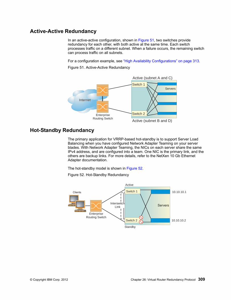
© Copyright IBM Corp. 2012 Chapter 26: Virtual Router Redundancy Protocol 309
Active-Active Redundancy
In an active-active configuration, shown in Figure 51, two switches provide redundancy for each other, with both active at the same time. Each switch processes traffic on a different subnet. When a failure occurs, the remaining switch can process traffic on all subnets.
For a configuration example, see “High Availability Configurations” on page 313.
Figure 51. Active-Active Redundancy
Hot-Standby Redundancy
The primary application for VRRP-based hot-standby is to support Server Load Balancing when you have configured Network Adapter Teaming on your server blades. With Network Adapter Teaming, the NICs on each server share the same IPv4 address, and are configured into a team. One NIC is the primary link, and the others are backup links. For more details, refer to the NetXen 10 Gb Ethernet Adapter documentation.
The hot-standby model is shown in Figure 52.
Figure 52. Hot-Standby Redundancy
InternetInternet
EnterpriseRouting Switch
Switch 1
Switch 2
Servers
Active (subnet A and C)
Active (subnet B and D)
EnterpriseRouting Switch
Active
Standby
InterswitchLink
10.10.10.1
10.10.10.2
Switch 1
Switch 2
310 EN4093 10Gb Scalable Switch: Application Guide
Virtual Router Group
The virtual router group ties all virtual routers on the switch together as a single entity. By definition, hot-standby requires that all virtual routers failover as a group, and not individually. As members of a group, all virtual routers on the switch (and therefore the switch itself), are in either a master or standby state.
The virtual router group cannot be used for active-active configurations or any other configuration that require shared interfaces.
A VRRP group has the following characteristics:
• When enabled, all virtual routers behave as one entity, and all group settings override any individual virtual router settings.
• All individual virtual routers, once the VRRP group is enabled, assume the group’s tracking and priority.
• When one member of a VRRP group fails, the priority of the group decreases, and the state of the entire switch changes from Master to Standby.
Each VRRP advertisement can include up to 128 addresses. All virtual routers are advertised within the same packet, conserving processing and buffering resources.
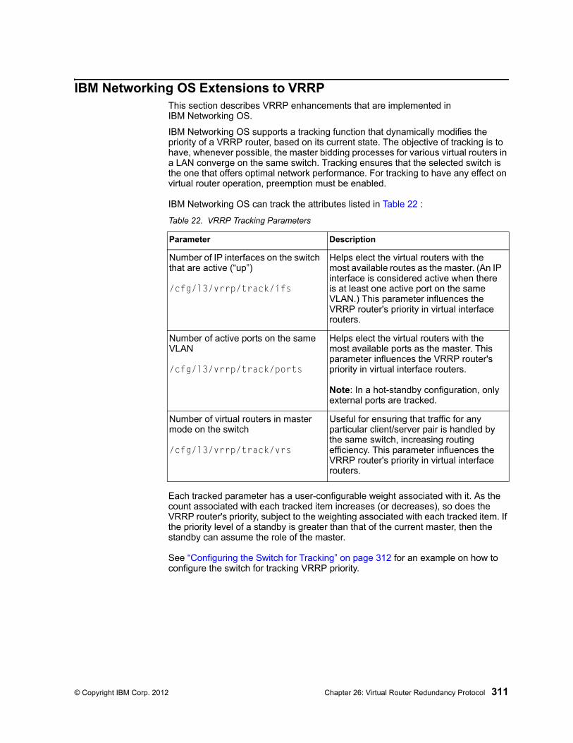
© Copyright IBM Corp. 2012 Chapter 26: Virtual Router Redundancy Protocol 311
IBM Networking OS Extensions to VRRPThis section describes VRRP enhancements that are implemented in IBM Networking OS.
IBM Networking OS supports a tracking function that dynamically modifies the priority of a VRRP router, based on its current state. The objective of tracking is to have, whenever possible, the master bidding processes for various virtual routers in a LAN converge on the same switch. Tracking ensures that the selected switch is the one that offers optimal network performance. For tracking to have any effect on virtual router operation, preemption must be enabled.
IBM Networking OS can track the attributes listed in Table 22 :
Each tracked parameter has a user-configurable weight associated with it. As the count associated with each tracked item increases (or decreases), so does the VRRP router's priority, subject to the weighting associated with each tracked item. If the priority level of a standby is greater than that of the current master, then the standby can assume the role of the master.
See “Configuring the Switch for Tracking” on page 312 for an example on how to configure the switch for tracking VRRP priority.
Table 22. VRRP Tracking Parameters
Parameter Description
Number of IP interfaces on the switch that are active (“up”)
/cfg/l3/vrrp/track/ifs
Helps elect the virtual routers with the most available routes as the master. (An IP interface is considered active when there is at least one active port on the same VLAN.) This parameter influences the VRRP router's priority in virtual interface routers.
Number of active ports on the same VLAN
/cfg/l3/vrrp/track/ports
Helps elect the virtual routers with the most available ports as the master. This parameter influences the VRRP router's priority in virtual interface routers.
Note: In a hot-standby configuration, only external ports are tracked.
Number of virtual routers in master mode on the switch
/cfg/l3/vrrp/track/vrs
Useful for ensuring that traffic for any particular client/server pair is handled by the same switch, increasing routing efficiency. This parameter influences the VRRP router's priority in virtual interface routers.
312 EN4093 10Gb Scalable Switch: Application Guide
Virtual Router Deployment Considerations
Assigning VRRP Virtual Router ID
During the software upgrade process, VRRP virtual router IDs will be automatically assigned if failover is enabled on the switch. When configuring virtual routers at any point after upgrade, virtual router ID numbers (/cfg/l3/vrrp/vr #/vrid) must be assigned. The virtual router ID may be configured as any number between 1 and 255.
Configuring the Switch for Tracking
Tracking configuration largely depends on user preferences and network environment. Consider the configuration shown in Figure 51 on page 309. Assume the following behavior on the network:
• Switch 1 is the master router upon initialization.
• If switch 1 is the master and it has one fewer active servers than switch 2, then switch 1 remains the master.
This behavior is preferred because running one server down is less disruptive than bringing a new master online and severing all active connections in the process.
• If switch 1 is the master and it has two or more active servers fewer than switch 2, then switch 2 becomes the master.
• If switch 2 is the master, it remains the master even if servers are restored on switch 1 such that it has one fewer or an equal number of servers.
• If switch 2 is the master and it has one active server fewer than switch 1, then switch 1 becomes the master.
The user can implement this behavior by configuring the switch for tracking as follows:
1. Set the priority for switch 1 to 101.
2. Leave the priority for switch 2 at the default value of 100.
3. On both switches, enable tracking based on ports (ports), interfaces (ifs), or virtual routers (vr). You can choose any combination of tracking parameters, based on your network configuration.
Note: There is no shortcut to setting tracking parameters. The goals must first be set and the outcomes of various configurations and scenarios analyzed to find settings that meet the goals.
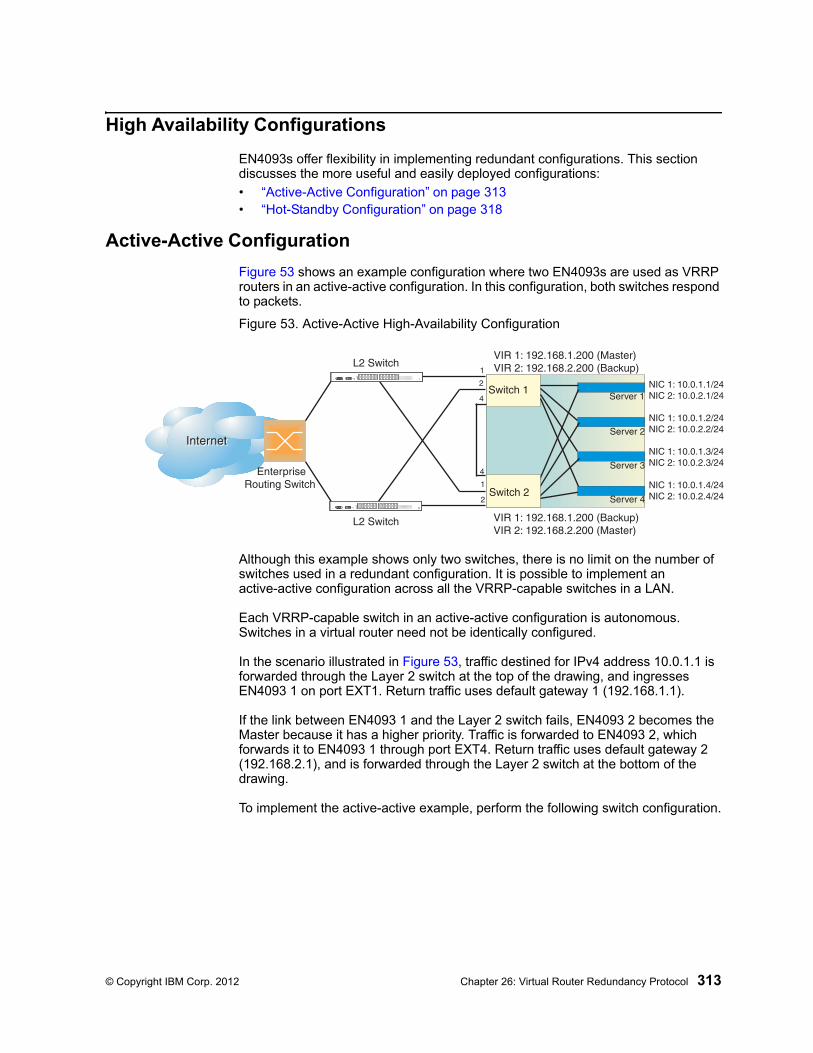
© Copyright IBM Corp. 2012 Chapter 26: Virtual Router Redundancy Protocol 313
High Availability Configurations
EN4093s offer flexibility in implementing redundant configurations. This section discusses the more useful and easily deployed configurations:
• “Active-Active Configuration” on page 313• “Hot-Standby Configuration” on page 318
Active-Active Configuration
Figure 53 shows an example configuration where two EN4093s are used as VRRP routers in an active-active configuration. In this configuration, both switches respond to packets.
Figure 53. Active-Active High-Availability Configuration
Although this example shows only two switches, there is no limit on the number of switches used in a redundant configuration. It is possible to implement an active-active configuration across all the VRRP-capable switches in a LAN.
Each VRRP-capable switch in an active-active configuration is autonomous. Switches in a virtual router need not be identically configured.
In the scenario illustrated in Figure 53, traffic destined for IPv4 address 10.0.1.1 is forwarded through the Layer 2 switch at the top of the drawing, and ingresses EN4093 1 on port EXT1. Return traffic uses default gateway 1 (192.168.1.1).
If the link between EN4093 1 and the Layer 2 switch fails, EN4093 2 becomes the Master because it has a higher priority. Traffic is forwarded to EN4093 2, which forwards it to EN4093 1 through port EXT4. Return traffic uses default gateway 2 (192.168.2.1), and is forwarded through the Layer 2 switch at the bottom of the drawing.
To implement the active-active example, perform the following switch configuration.
InternetInternet
EnterpriseRouting Switch
Switch 1
Switch 2
Server 1
VIR 1: 192.168.1.200 (Master)VIR 2: 192.168.2.200 (Backup)
VIR 1: 192.168.1.200 (Backup)VIR 2: 192.168.2.200 (Master)
NIC 1: 10.0.1.1/24NIC 2: 10.0.2.1/24
NIC 1: 10.0.1.2/24NIC 2: 10.0.2.2/24
NIC 1: 10.0.1.3/24NIC 2: 10.0.2.3/24
NIC 1: 10.0.1.4/24NIC 2: 10.0.2.4/24
Server 2
Server 3
Server 4
L2 Switch
L2 Switch1
2
4
4
1
2
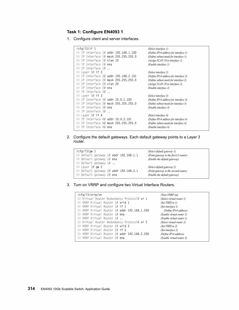
314 EN4093 10Gb Scalable Switch: Application Guide
Task 1: Configure EN4093 1
1. Configure client and server interfaces.
2. Configure the default gateways. Each default gateway points to a Layer 3 router.
3. Turn on VRRP and configure two Virtual Interface Routers.
/cfg/l3/if 1 (Select interface 1)>> IP Interface 1# addr 192.168.1.100 (Define IPv4 address for interface 1)>> IP Interface 1# mask 255.255.255.0 (Define subnet mask for interface 1)>> IP Interface 1# vlan 10 (Assign VLAN 10 to interface 1)>> IP Interface 1# ena (Enable interface 1)>> IP Interface 1# ..>> Layer 3# if 2 (Select interface 2)>> IP Interface 2# addr 192.168.2.101 (Define IPv4 address for interface 2)>> IP Interface 2# mask 255.255.255.0 (Define subnet mask for interface 2)>> IP Interface 2# vlan 20 (Assign VLAN 20 to interface 2)>> IP Interface 2# ena (Enable interface 2)>> IP Interface 2# ..>> Layer 3# if 3 (Select interface 3)>> IP Interface 3# addr 10.0.1.100 (Define IPv4 address for interface 3)>> IP Interface 3# mask 255.255.255.0 (Define subnet mask for interface 3)>> IP Interface 3# ena (Enable interface 3)>> IP Interface 3# ..>> Layer 3# if 4 (Select interface 4)>> IP Interface 4# addr 10.0.2.101 (Define IPv4 address for interface 4)>> IP Interface 4# mask 255.255.255.0 (Define subnet mask for interface 4)>> IP Interface 4# ena (Enable interface 4)
/cfg/l3/gw 1 (Select default gateway 1)>> Default gateway 1# addr 192.168.1.1 (Point gateway to the first L3 router)>> Default gateway 1# ena (Enable the default gateway)>> Default gateway 1# ..>> Layer 3# gw 2 (Select default gateway 2)>> Default gateway 2# addr 192.168.2.1 (Point gateway to the second router)>> Default gateway 2# ena (Enable the default gateway)
/cfg/l3/vrrp/on (Turn VRRP on)>> Virtual Router Redundancy Protocol# vr 1 (Select virtual router 1)>> VRRP Virtual Router 1# vrid 1 (Set VRID to 1)>> VRRP Virtual Router 1# if 1 (Set interface 1)>> VRRP Virtual Router 1# addr 192.168.1.200 (Define IPv4 address)>> VRRP Virtual Router 1# ena (Enable virtual router 1)>> VRRP Virtual Router 1# .. (Enable virtual router 1)>> Virtual Router Redundancy Protocol# vr 2 (Select virtual router 2)>> VRRP Virtual Router 2# vrid 2 (Set VRID to 2)>> VRRP Virtual Router 2# if 2 (Set interface 2)>> VRRP Virtual Router 2# addr 192.168.2.200 (Define IPv4 address)>> VRRP Virtual Router 2# ena (Enable virtual router 2)
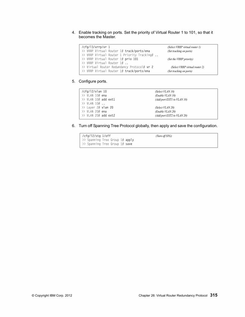
© Copyright IBM Corp. 2012 Chapter 26: Virtual Router Redundancy Protocol 315
4. Enable tracking on ports. Set the priority of Virtual Router 1 to 101, so that it becomes the Master.
5. Configure ports.
6. Turn off Spanning Tree Protocol globally, then apply and save the configuration.
/cfg/l3/vrrp/vr 1 (Select VRRP virtual router 1)>> VRRP Virtual Router 1# track/ports/ena (Set tracking on ports)>> VRRP Virtual Router 1 Priority Tracking# ..>> VRRP Virtual Router 1# prio 101 (Set the VRRP priority)>> VRRP Virtual Router 1# ..>> Virtual Router Redundancy Protocol# vr 2 (Select VRRP virtual router 2)>> VRRP Virtual Router 1# track/ports/ena (Set tracking on ports)
/cfg/l2/vlan 10 (Select VLAN 10)>> VLAN 10# ena (Enable VLAN 10)>> VLAN 10# add ext1 (Add port EXT1 to VLAN 10)>> VLAN 10# ..>> Layer 2# vlan 20 (Select VLAN 20)>> VLAN 20# ena (Enable VLAN 20)>> VLAN 20# add ext2 (Add port EXT2 to VLAN 20)
/cfg/l2/stg 1/off (Turn off STG)>> Spanning Tree Group 1# apply>> Spanning Tree Group 1# save
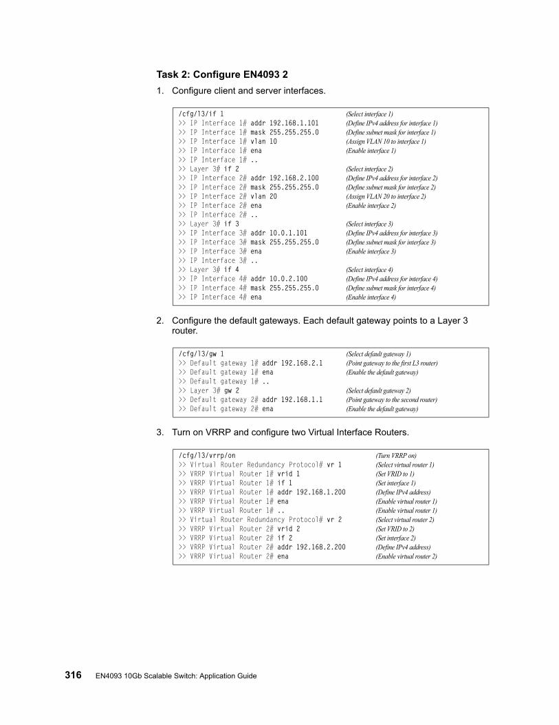
316 EN4093 10Gb Scalable Switch: Application Guide
Task 2: Configure EN4093 2
1. Configure client and server interfaces.
2. Configure the default gateways. Each default gateway points to a Layer 3 router.
3. Turn on VRRP and configure two Virtual Interface Routers.
/cfg/l3/if 1 (Select interface 1)>> IP Interface 1# addr 192.168.1.101 (Define IPv4 address for interface 1)>> IP Interface 1# mask 255.255.255.0 (Define subnet mask for interface 1)>> IP Interface 1# vlan 10 (Assign VLAN 10 to interface 1)>> IP Interface 1# ena (Enable interface 1)>> IP Interface 1# ..>> Layer 3# if 2 (Select interface 2)>> IP Interface 2# addr 192.168.2.100 (Define IPv4 address for interface 2)>> IP Interface 2# mask 255.255.255.0 (Define subnet mask for interface 2)>> IP Interface 2# vlan 20 (Assign VLAN 20 to interface 2)>> IP Interface 2# ena (Enable interface 2)>> IP Interface 2# ..>> Layer 3# if 3 (Select interface 3)>> IP Interface 3# addr 10.0.1.101 (Define IPv4 address for interface 3)>> IP Interface 3# mask 255.255.255.0 (Define subnet mask for interface 3)>> IP Interface 3# ena (Enable interface 3)>> IP Interface 3# ..>> Layer 3# if 4 (Select interface 4)>> IP Interface 4# addr 10.0.2.100 (Define IPv4 address for interface 4)>> IP Interface 4# mask 255.255.255.0 (Define subnet mask for interface 4)>> IP Interface 4# ena (Enable interface 4)
/cfg/l3/gw 1 (Select default gateway 1)>> Default gateway 1# addr 192.168.2.1 (Point gateway to the first L3 router)>> Default gateway 1# ena (Enable the default gateway)>> Default gateway 1# ..>> Layer 3# gw 2 (Select default gateway 2)>> Default gateway 2# addr 192.168.1.1 (Point gateway to the second router)>> Default gateway 2# ena (Enable the default gateway)
/cfg/l3/vrrp/on (Turn VRRP on)>> Virtual Router Redundancy Protocol# vr 1 (Select virtual router 1)>> VRRP Virtual Router 1# vrid 1 (Set VRID to 1)>> VRRP Virtual Router 1# if 1 (Set interface 1)>> VRRP Virtual Router 1# addr 192.168.1.200 (Define IPv4 address)>> VRRP Virtual Router 1# ena (Enable virtual router 1)>> VRRP Virtual Router 1# .. (Enable virtual router 1)>> Virtual Router Redundancy Protocol# vr 2 (Select virtual router 2)>> VRRP Virtual Router 2# vrid 2 (Set VRID to 2)>> VRRP Virtual Router 2# if 2 (Set interface 2)>> VRRP Virtual Router 2# addr 192.168.2.200 (Define IPv4 address)>> VRRP Virtual Router 2# ena (Enable virtual router 2)
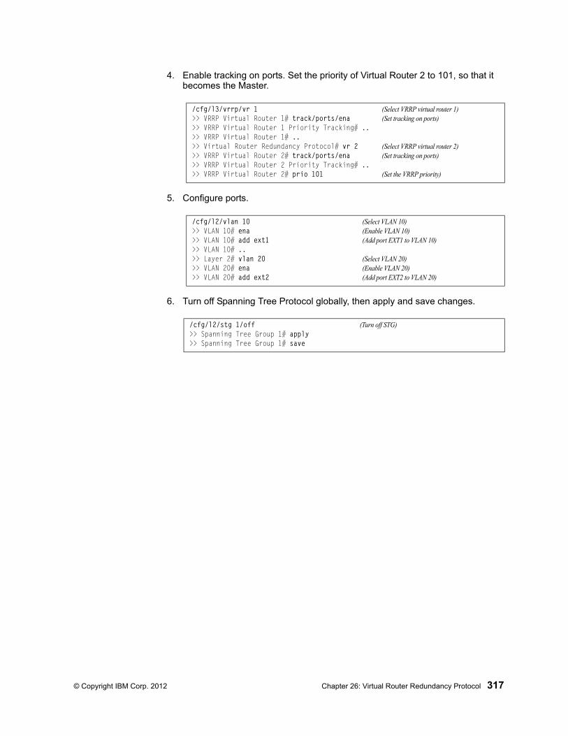
© Copyright IBM Corp. 2012 Chapter 26: Virtual Router Redundancy Protocol 317
4. Enable tracking on ports. Set the priority of Virtual Router 2 to 101, so that it becomes the Master.
5. Configure ports.
6. Turn off Spanning Tree Protocol globally, then apply and save changes.
/cfg/l3/vrrp/vr 1 (Select VRRP virtual router 1)>> VRRP Virtual Router 1# track/ports/ena (Set tracking on ports)>> VRRP Virtual Router 1 Priority Tracking# ..>> VRRP Virtual Router 1# ..>> Virtual Router Redundancy Protocol# vr 2 (Select VRRP virtual router 2)>> VRRP Virtual Router 2# track/ports/ena (Set tracking on ports)>> VRRP Virtual Router 2 Priority Tracking# ..>> VRRP Virtual Router 2# prio 101 (Set the VRRP priority)
/cfg/l2/vlan 10 (Select VLAN 10)>> VLAN 10# ena (Enable VLAN 10)>> VLAN 10# add ext1 (Add port EXT1 to VLAN 10)>> VLAN 10# ..>> Layer 2# vlan 20 (Select VLAN 20)>> VLAN 20# ena (Enable VLAN 20)>> VLAN 20# add ext2 (Add port EXT2 to VLAN 20)
/cfg/l2/stg 1/off (Turn off STG)>> Spanning Tree Group 1# apply>> Spanning Tree Group 1# save
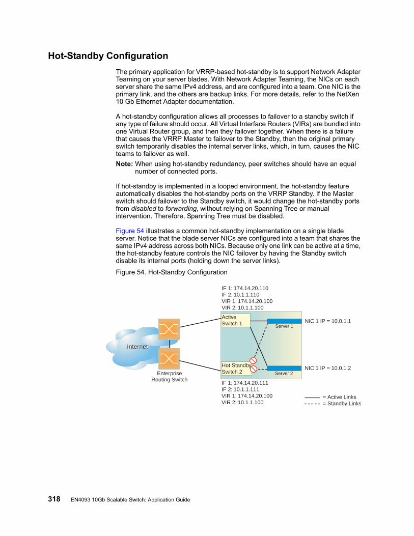
318 EN4093 10Gb Scalable Switch: Application Guide
Hot-Standby Configuration
The primary application for VRRP-based hot-standby is to support Network Adapter Teaming on your server blades. With Network Adapter Teaming, the NICs on each server share the same IPv4 address, and are configured into a team. One NIC is the primary link, and the others are backup links. For more details, refer to the NetXen 10 Gb Ethernet Adapter documentation.
A hot-standby configuration allows all processes to failover to a standby switch if any type of failure should occur. All Virtual Interface Routers (VIRs) are bundled into one Virtual Router group, and then they failover together. When there is a failure that causes the VRRP Master to failover to the Standby, then the original primary switch temporarily disables the internal server links, which, in turn, causes the NIC teams to failover as well.
Note: When using hot-standby redundancy, peer switches should have an equal number of connected ports.
If hot-standby is implemented in a looped environment, the hot-standby feature automatically disables the hot-standby ports on the VRRP Standby. If the Master switch should failover to the Standby switch, it would change the hot-standby ports from disabled to forwarding, without relying on Spanning Tree or manual intervention. Therefore, Spanning Tree must be disabled.
Figure 54 illustrates a common hot-standby implementation on a single blade server. Notice that the blade server NICs are configured into a team that shares the same IPv4 address across both NICs. Because only one link can be active at a time, the hot-standby feature controls the NIC failover by having the Standby switch disable its internal ports (holding down the server links).
Figure 54. Hot-Standby Configuration
InternetInternet
EnterpriseRouting Switch
Server 2
ActiveSwitch 1
Hot StandbySwitch 2
NIC 1 IP = 10.0.1.1Server 1
NIC 1 IP = 10.0.1.2
IF 1: 174.14.20.110IF 2: 10.1.1.110VIR 1: 174.14.20.100VIR 2: 10.1.1.100
IF 1: 174.14.20.111IF 2: 10.1.1.111VIR 1: 174.14.20.100VIR 2: 10.1.1.100
= Active Links= Standby Links
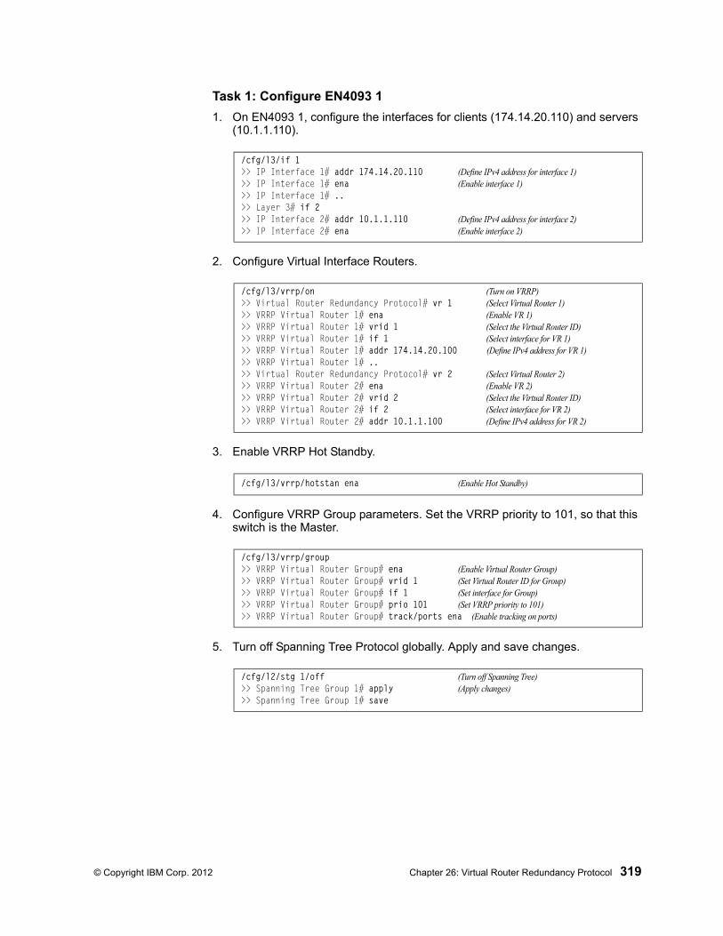
© Copyright IBM Corp. 2012 Chapter 26: Virtual Router Redundancy Protocol 319
Task 1: Configure EN4093 1
1. On EN4093 1, configure the interfaces for clients (174.14.20.110) and servers (10.1.1.110).
2. Configure Virtual Interface Routers.
3. Enable VRRP Hot Standby.
4. Configure VRRP Group parameters. Set the VRRP priority to 101, so that this switch is the Master.
5. Turn off Spanning Tree Protocol globally. Apply and save changes.
/cfg/l3/if 1>> IP Interface 1# addr 174.14.20.110 (Define IPv4 address for interface 1)>> IP Interface 1# ena (Enable interface 1)>> IP Interface 1# ..>> Layer 3# if 2>> IP Interface 2# addr 10.1.1.110 (Define IPv4 address for interface 2)>> IP Interface 2# ena (Enable interface 2)
/cfg/l3/vrrp/on (Turn on VRRP)>> Virtual Router Redundancy Protocol# vr 1 (Select Virtual Router 1)>> VRRP Virtual Router 1# ena (Enable VR 1)>> VRRP Virtual Router 1# vrid 1 (Select the Virtual Router ID)>> VRRP Virtual Router 1# if 1 (Select interface for VR 1)>> VRRP Virtual Router 1# addr 174.14.20.100 (Define IPv4 address for VR 1)>> VRRP Virtual Router 1# ..>> Virtual Router Redundancy Protocol# vr 2 (Select Virtual Router 2)>> VRRP Virtual Router 2# ena (Enable VR 2)>> VRRP Virtual Router 2# vrid 2 (Select the Virtual Router ID)>> VRRP Virtual Router 2# if 2 (Select interface for VR 2)>> VRRP Virtual Router 2# addr 10.1.1.100 (Define IPv4 address for VR 2)
/cfg/l3/vrrp/hotstan ena (Enable Hot Standby)
/cfg/l3/vrrp/group>> VRRP Virtual Router Group# ena (Enable Virtual Router Group)>> VRRP Virtual Router Group# vrid 1 (Set Virtual Router ID for Group)>> VRRP Virtual Router Group# if 1 (Set interface for Group)>> VRRP Virtual Router Group# prio 101 (Set VRRP priority to 101)>> VRRP Virtual Router Group# track/ports ena (Enable tracking on ports)
/cfg/l2/stg 1/off (Turn off Spanning Tree)>> Spanning Tree Group 1# apply (Apply changes)>> Spanning Tree Group 1# save
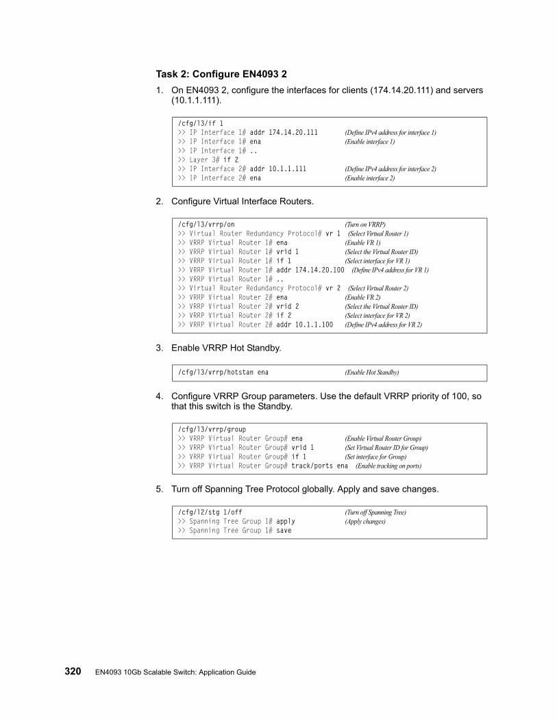
320 EN4093 10Gb Scalable Switch: Application Guide
Task 2: Configure EN4093 2
1. On EN4093 2, configure the interfaces for clients (174.14.20.111) and servers (10.1.1.111).
2. Configure Virtual Interface Routers.
3. Enable VRRP Hot Standby.
4. Configure VRRP Group parameters. Use the default VRRP priority of 100, so that this switch is the Standby.
5. Turn off Spanning Tree Protocol globally. Apply and save changes.
/cfg/l3/if 1>> IP Interface 1# addr 174.14.20.111 (Define IPv4 address for interface 1)>> IP Interface 1# ena (Enable interface 1)>> IP Interface 1# ..>> Layer 3# if 2>> IP Interface 2# addr 10.1.1.111 (Define IPv4 address for interface 2)>> IP Interface 2# ena (Enable interface 2)
/cfg/l3/vrrp/on (Turn on VRRP)>> Virtual Router Redundancy Protocol# vr 1 (Select Virtual Router 1)>> VRRP Virtual Router 1# ena (Enable VR 1)>> VRRP Virtual Router 1# vrid 1 (Select the Virtual Router ID)>> VRRP Virtual Router 1# if 1 (Select interface for VR 1)>> VRRP Virtual Router 1# addr 174.14.20.100 (Define IPv4 address for VR 1)>> VRRP Virtual Router 1# ..>> Virtual Router Redundancy Protocol# vr 2 (Select Virtual Router 2)>> VRRP Virtual Router 2# ena (Enable VR 2)>> VRRP Virtual Router 2# vrid 2 (Select the Virtual Router ID)>> VRRP Virtual Router 2# if 2 (Select interface for VR 2)>> VRRP Virtual Router 2# addr 10.1.1.100 (Define IPv4 address for VR 2)
/cfg/l3/vrrp/hotstan ena (Enable Hot Standby)
/cfg/l3/vrrp/group>> VRRP Virtual Router Group# ena (Enable Virtual Router Group)>> VRRP Virtual Router Group# vrid 1 (Set Virtual Router ID for Group)>> VRRP Virtual Router Group# if 1 (Set interface for Group)>> VRRP Virtual Router Group# track/ports ena (Enable tracking on ports)
/cfg/l2/stg 1/off (Turn off Spanning Tree)>> Spanning Tree Group 1# apply (Apply changes)>> Spanning Tree Group 1# save

© Copyright IBM Corp. 2012 321
Part 7: Network Manage-ment

322 EN4093 10Gb Scalable Switch: Application Guide
© Copyright IBM Corp. 2012 323
Chapter 27. Link Layer Discovery Protocol
The IBM Networking OS software support Link Layer Discovery Protocol (LLDP). This chapter discusses the use and configuration of LLDP on the switch:
• “LLDP Overview” on page 323
• “Enabling or Disabling LLDP” on page 324
• “LLDP Transmit Features” on page 325
• “LLDP Receive Features” on page 329
• “LLDP Example Configuration” on page 331
LLDP Overview
Link Layer Discovery Protocol (LLDP) is an IEEE 802.1AB-2005 standard for discovering and managing network devices. LLDP uses Layer 2 (the data link layer), and allows network management applications to extend their awareness of the network by discovering devices that are direct neighbors of already known devices.
With LLDP, the EN4093 can advertise the presence of its ports, their major capabilities, and their current status to other LLDP stations in the same LAN. LLDP transmissions occur on ports at regular intervals or whenever there is a relevant change to their status. The switch can also receive LLDP information advertised from adjacent LLDP-capable network devices.
In addition to discovery of network resources, and notification of network changes, LLDP can help administrators quickly recognize a variety of common network configuration problems, such as unintended VLAN exclusions or mis-matched port aggregation membership.
The LLDP transmit function and receive function can be independently configured on a per-port basis. The administrator can allow any given port to transmit only, receive only, or both transmit and receive LLDP information.
The LLDP information to be distributed by the EN4093 ports, and that which has been collected from other LLDP stations, is stored in the switch’s Management Information Base (MIB). Network Management Systems (NMS) can use Simple Network Management Protocol (SNMP) to access this MIB information. LLDP-related MIB information is read-only.
Changes, either to the local switch LLDP information or to the remotely received LLDP information, are flagged within the MIB for convenient tracking by SNMP-based management systems.
For LLDP to provide expected benefits, all network devices that support LLDP should be consistent in their LLDP configuration.
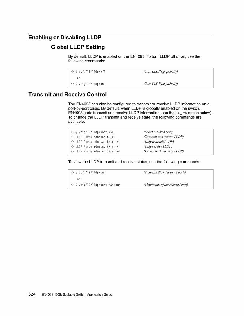
324 EN4093 10Gb Scalable Switch: Application Guide
Enabling or Disabling LLDP
Global LLDP Setting
By default, LLDP is enabled on the EN4093. To turn LLDP off or on, use the following commands:
Transmit and Receive Control
The EN4093 can also be configured to transmit or receive LLDP information on a port-by-port basis. By default, when LLDP is globally enabled on the switch, EN4093 ports transmit and receive LLDP information (see the tx_rx option below). To change the LLDP transmit and receive state, the following commands are available:
To view the LLDP transmit and receive status, use the following commands:
>> # /cfg/l2/lldp/off (Turn LLDP off globally)
or
>> # /cfg/l2/lldp/on (Turn LLDP on globally)
>> # /cfg/l2/lldp/port <n> (Select a switch port)>> LLDP Port# admstat tx_rx (Transmit and receive LLDP)>> LLDP Port# admstat tx_only (Only transmit LLDP)>> LLDP Port# admstat rx_only (Only receive LLDP)>> LLDP Port# admstat disabled (Do not participate in LLDP)
>> # /cfg/l2/lldp/cur (View LLDP status of all ports)
or
>> # /cfg/l2/lldp/port <n>/cur (View status of the selected port)
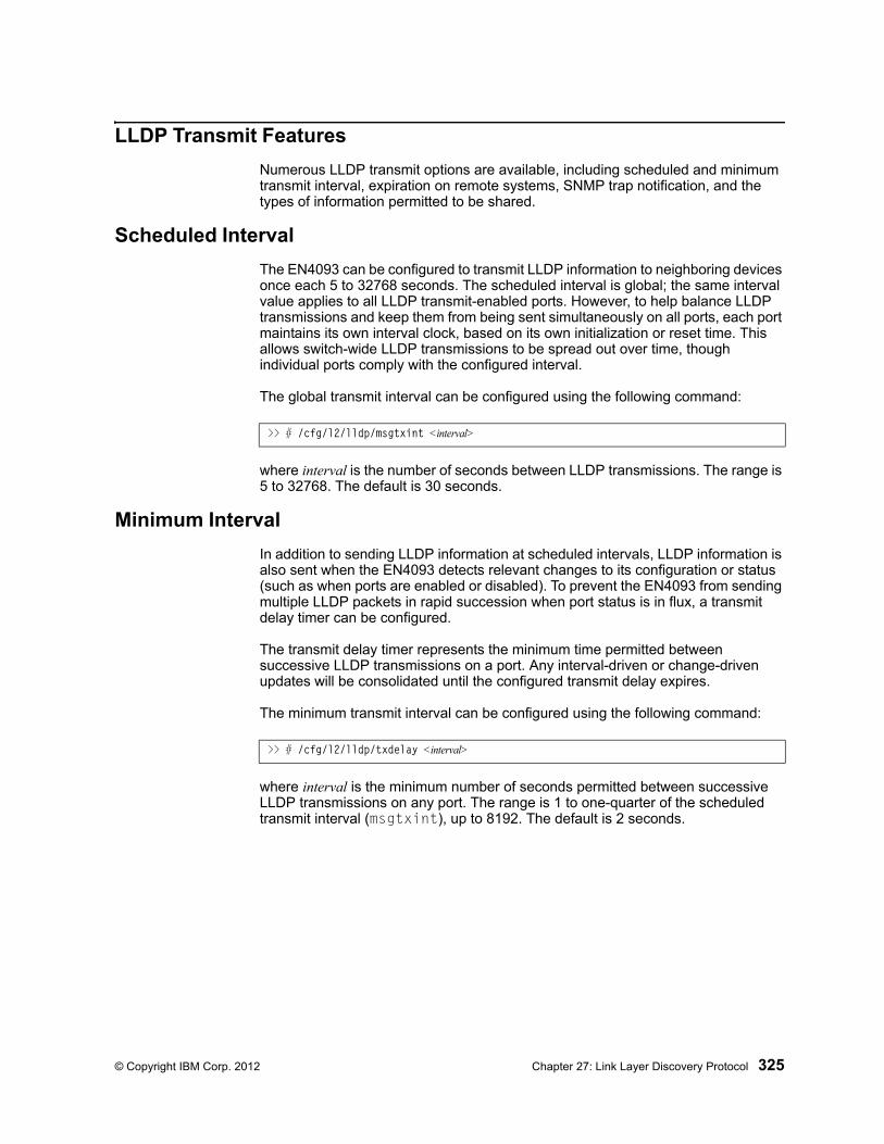
© Copyright IBM Corp. 2012 Chapter 27: Link Layer Discovery Protocol 325
LLDP Transmit Features
Numerous LLDP transmit options are available, including scheduled and minimum transmit interval, expiration on remote systems, SNMP trap notification, and the types of information permitted to be shared.
Scheduled Interval
The EN4093 can be configured to transmit LLDP information to neighboring devices once each 5 to 32768 seconds. The scheduled interval is global; the same interval value applies to all LLDP transmit-enabled ports. However, to help balance LLDP transmissions and keep them from being sent simultaneously on all ports, each port maintains its own interval clock, based on its own initialization or reset time. This allows switch-wide LLDP transmissions to be spread out over time, though individual ports comply with the configured interval.
The global transmit interval can be configured using the following command:
where interval is the number of seconds between LLDP transmissions. The range is 5 to 32768. The default is 30 seconds.
Minimum Interval
In addition to sending LLDP information at scheduled intervals, LLDP information is also sent when the EN4093 detects relevant changes to its configuration or status (such as when ports are enabled or disabled). To prevent the EN4093 from sending multiple LLDP packets in rapid succession when port status is in flux, a transmit delay timer can be configured.
The transmit delay timer represents the minimum time permitted between successive LLDP transmissions on a port. Any interval-driven or change-driven updates will be consolidated until the configured transmit delay expires.
The minimum transmit interval can be configured using the following command:
where interval is the minimum number of seconds permitted between successive LLDP transmissions on any port. The range is 1 to one-quarter of the scheduled transmit interval (msgtxint), up to 8192. The default is 2 seconds.
>> # /cfg/l2/lldp/msgtxint <interval>
>> # /cfg/l2/lldp/txdelay <interval>
326 EN4093 10Gb Scalable Switch: Application Guide
Time-to-Live for Transmitted Information
The transmitted LLDP information is held by remote systems for a limited time. A time-to-live parameter allows the switch to determine how long the transmitted data should be held before it expires. The hold time is configured as a multiple of the configured transmission interval.
where multiplier is a value between 2 and 10. The default value is 4, meaning that remote systems will hold the port’s LLDP information for 4 x the 30-second msgtxint value, or 120 seconds, before removing it from their MIB.
Trap Notifications
If SNMP is enabled on the EN4093 (see “Using Simple Network Management Protocol” on page 16), each port can be configured to send SNMP trap notifications whenever LLDP transmissions are sent. By default, trap notification is disabled for each port. The trap notification state can be changed using the following commands:
In addition to sending LLDP information at scheduled intervals, LLDP information is also sent when the EN4093 detects relevant changes to its configuration or status (such as when ports are enabled or disabled). To prevent the EN4093 from sending multiple trap notifications in rapid succession when port status is in flux, a global trap delay timer can be configured.
The trap delay timer represents the minimum time permitted between successive trap notifications on any port. Any interval-driven or change-driven trap notices from the port will be consolidated until the configured trap delay expires.
The minimum trap notification interval can be configured using the following command:
where interval is the minimum number of seconds permitted between successive LLDP transmissions on any port. The range is 1 to 3600. The default is 5 seconds.
If SNMP trap notification is enabled, the notification messages can also appear in the system log. This is enabled by default. To change whether the SNMP trap notifications for LLDP events appear in the system log, use the following commands:
>> # /cfg/l2/lldp/msgtxhld <multiplier>
>> # /cfg/l2/lldp/port <n>/snmptrap ena (Send SNMP trap notifications)
or
>> # /cfg/l2/lldp/port <n>/snmptrap dis (Do not send trap notifications)
>> # /cfg/l2/lldp/notifint <interval>
>> # /cfg/sys/syslog/log lldp ena (Add LLDP notification to Syslog)
or
>> # /cfg/sys/syslog/log lldp dis (Do not log LLDP notifications)
© Copyright IBM Corp. 2012 Chapter 27: Link Layer Discovery Protocol 327
Changing the LLDP Transmit State
When the port is disabled, or when LLDP transmit is turned off for the port using the admstat command’s rx_only or disabled options (see “Transmit and Receive Control” on page 324), a final LLDP packet is transmitted with a time-to-live value of 0. Neighbors that receive this packet will remove the LLDP information associated with the EN4093 port from their MIB.
In addition, if LLDP is fully disabled on a port (using admstat disabled) and later re-enabled, the EN4093 will temporarily delay resuming LLDP transmissions on the port in order to allow the port LLDP information to stabilize. The reinitialization delay interval can be globally configured for all ports using the following command:
where interval is the number of seconds to wait before resuming LLDP transmissions. The range is between 1 and 10. The default is 2 seconds.
>> # /cfg/l2/lldp/redelay <interval>
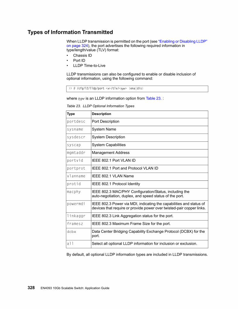
328 EN4093 10Gb Scalable Switch: Application Guide
Types of Information Transmitted
When LLDP transmission is permitted on the port (see “Enabling or Disabling LLDP” on page 324), the port advertises the following required information in type/length/value (TLV) format:
• Chassis ID• Port ID• LLDP Time-to-Live
LLDP transmissions can also be configured to enable or disable inclusion of optional information, using the following command:
where type is an LLDP information option from Table 23. :
By default, all optional LLDP information types are included in LLDP transmissions.
>> # /cfg/l2/lldp/port <n>/tlv/<type> {ena|dis}
Table 23. LLDP Optional Information Types
Type Description
portdesc Port Description
sysname System Name
sysdescr System Description
syscap System Capabilities
mgmtaddr Management Address
portvid IEEE 802.1 Port VLAN ID
portprot IEEE 802.1 Port and Protocol VLAN ID
vlanname IEEE 802.1 VLAN Name
protid IEEE 802.1 Protocol Identity
macphy IEEE 802.3 MAC/PHY Configuration/Status, including the auto-negotiation, duplex, and speed status of the port.
powermdi IEEE 802.3 Power via MDI, indicating the capabilities and status of devices that require or provide power over twisted-pair copper links.
linkaggr IEEE 802.3 Link Aggregation status for the port.
framesz IEEE 802.3 Maximum Frame Size for the port.
dcbx Data Center Bridging Capability Exchange Protocol (DCBX) for the port.
all Select all optional LLDP information for inclusion or exclusion.
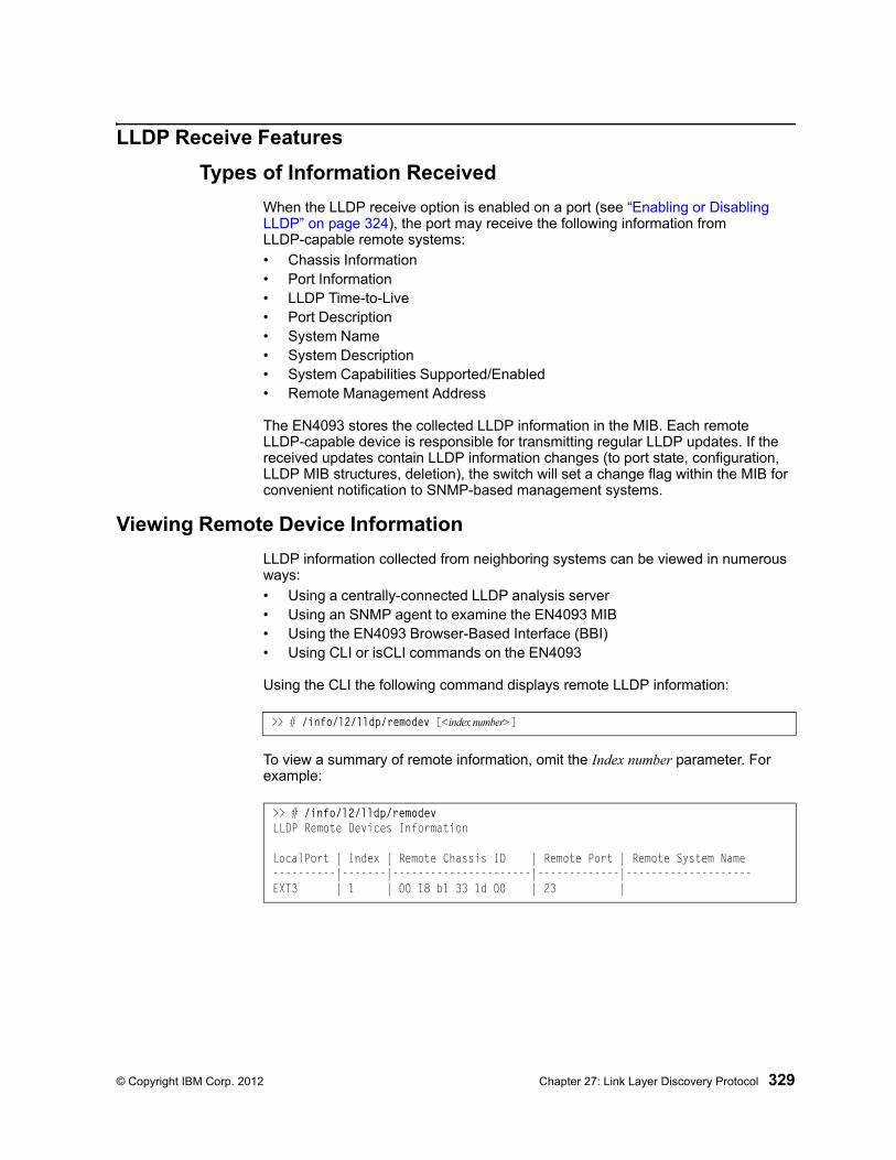
© Copyright IBM Corp. 2012 Chapter 27: Link Layer Discovery Protocol 329
LLDP Receive Features
Types of Information Received
When the LLDP receive option is enabled on a port (see “Enabling or Disabling LLDP” on page 324), the port may receive the following information from LLDP-capable remote systems:
• Chassis Information• Port Information• LLDP Time-to-Live• Port Description• System Name• System Description• System Capabilities Supported/Enabled• Remote Management Address
The EN4093 stores the collected LLDP information in the MIB. Each remote LLDP-capable device is responsible for transmitting regular LLDP updates. If the received updates contain LLDP information changes (to port state, configuration, LLDP MIB structures, deletion), the switch will set a change flag within the MIB for convenient notification to SNMP-based management systems.
Viewing Remote Device Information
LLDP information collected from neighboring systems can be viewed in numerous ways:
• Using a centrally-connected LLDP analysis server• Using an SNMP agent to examine the EN4093 MIB• Using the EN4093 Browser-Based Interface (BBI)• Using CLI or isCLI commands on the EN4093
Using the CLI the following command displays remote LLDP information:
To view a summary of remote information, omit the Index number parameter. For example:
>> # /info/l2/lldp/remodev [<index number>]
>> # /info/l2/lldp/remodevLLDP Remote Devices Information
LocalPort | Index | Remote Chassis ID | Remote Port | Remote System Name----------|-------|----------------------|-------------|--------------------EXT3 | 1 | 00 18 b1 33 1d 00 | 23 |
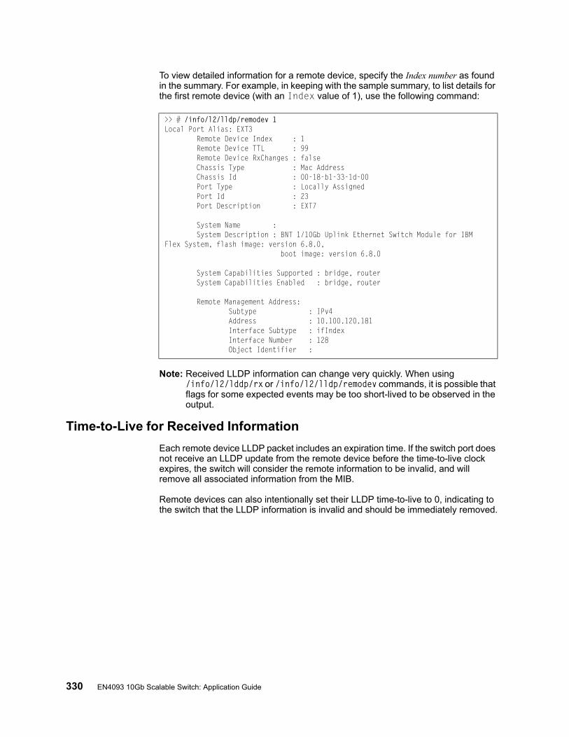
330 EN4093 10Gb Scalable Switch: Application Guide
To view detailed information for a remote device, specify the Index number as found in the summary. For example, in keeping with the sample summary, to list details for the first remote device (with an Index value of 1), use the following command:
Note: Received LLDP information can change very quickly. When using /info/l2/lddp/rx or /info/l2/lldp/remodev commands, it is possible that flags for some expected events may be too short-lived to be observed in the output.
Time-to-Live for Received Information
Each remote device LLDP packet includes an expiration time. If the switch port does not receive an LLDP update from the remote device before the time-to-live clock expires, the switch will consider the remote information to be invalid, and will remove all associated information from the MIB.
Remote devices can also intentionally set their LLDP time-to-live to 0, indicating to the switch that the LLDP information is invalid and should be immediately removed.
>> # /info/l2/lldp/remodev 1Local Port Alias: EXT3 Remote Device Index : 1 Remote Device TTL : 99 Remote Device RxChanges : false Chassis Type : Mac Address Chassis Id : 00-18-b1-33-1d-00 Port Type : Locally Assigned Port Id : 23 Port Description : EXT7
System Name : System Description : BNT 1/10Gb Uplink Ethernet Switch Module for IBM Flex System, flash image: version 6.8.0, boot image: version 6.8.0
System Capabilities Supported : bridge, router System Capabilities Enabled : bridge, router
Remote Management Address: Subtype : IPv4 Address : 10.100.120.181 Interface Subtype : ifIndex Interface Number : 128 Object Identifier :
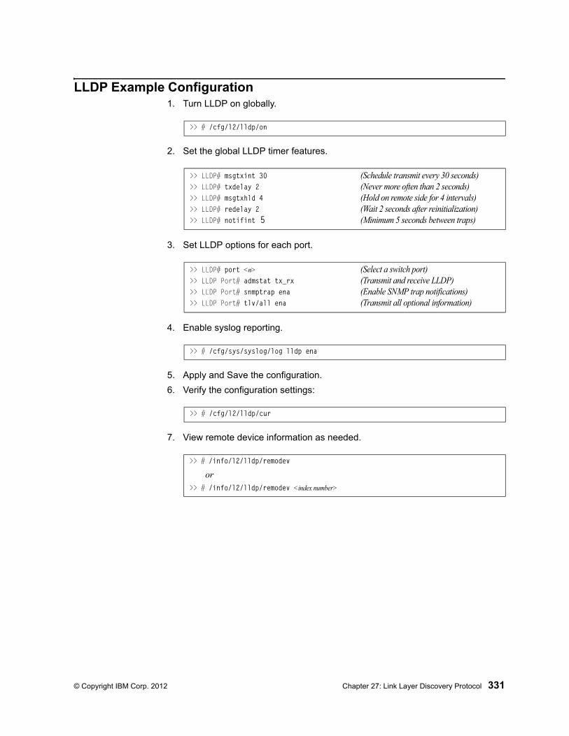
© Copyright IBM Corp. 2012 Chapter 27: Link Layer Discovery Protocol 331
LLDP Example Configuration1. Turn LLDP on globally.
2. Set the global LLDP timer features.
3. Set LLDP options for each port.
4. Enable syslog reporting.
5. Apply and Save the configuration.
6. Verify the configuration settings:
7. View remote device information as needed.
>> # /cfg/l2/lldp/on
>> LLDP# msgtxint 30 (Schedule transmit every 30 seconds)>> LLDP# txdelay 2 (Never more often than 2 seconds)>> LLDP# msgtxhld 4 (Hold on remote side for 4 intervals)>> LLDP# redelay 2 (Wait 2 seconds after reinitialization)>> LLDP# notifint 5 (Minimum 5 seconds between traps)
>> LLDP# port <n> (Select a switch port)>> LLDP Port# admstat tx_rx (Transmit and receive LLDP)>> LLDP Port# snmptrap ena (Enable SNMP trap notifications)>> LLDP Port# tlv/all ena (Transmit all optional information)
>> # /cfg/sys/syslog/log lldp ena
>> # /cfg/l2/lldp/cur
>> # /info/l2/lldp/remodev
or>> # /info/l2/lldp/remodev <index number>

332 EN4093 10Gb Scalable Switch: Application Guide
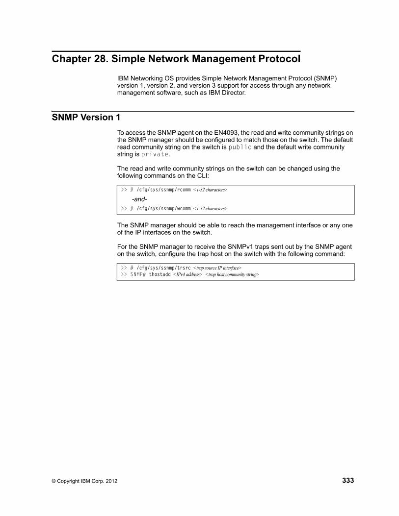
© Copyright IBM Corp. 2012 333
Chapter 28. Simple Network Management Protocol
IBM Networking OS provides Simple Network Management Protocol (SNMP) version 1, version 2, and version 3 support for access through any network management software, such as IBM Director.
SNMP Version 1
To access the SNMP agent on the EN4093, the read and write community strings on the SNMP manager should be configured to match those on the switch. The default read community string on the switch is public and the default write community string is private.
The read and write community strings on the switch can be changed using the following commands on the CLI:
The SNMP manager should be able to reach the management interface or any one of the IP interfaces on the switch.
For the SNMP manager to receive the SNMPv1 traps sent out by the SNMP agent on the switch, configure the trap host on the switch with the following command:
>> # /cfg/sys/ssnmp/rcomm <1-32 characters>
-and->> # /cfg/sys/ssnmp/wcomm <1-32 characters>
>> # /cfg/sys/ssnmp/trsrc <trap source IP interface>>> SNMP# thostadd <IPv4 address> <trap host community string>
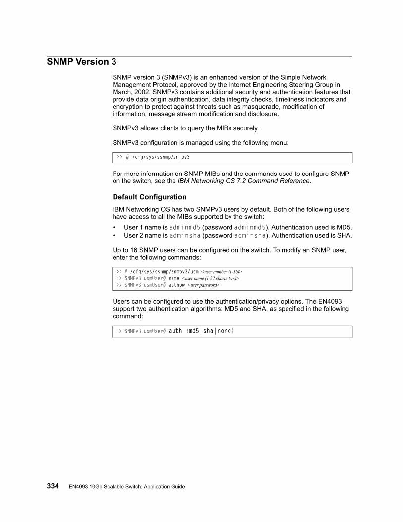
334 EN4093 10Gb Scalable Switch: Application Guide
SNMP Version 3
SNMP version 3 (SNMPv3) is an enhanced version of the Simple Network Management Protocol, approved by the Internet Engineering Steering Group in March, 2002. SNMPv3 contains additional security and authentication features that provide data origin authentication, data integrity checks, timeliness indicators and encryption to protect against threats such as masquerade, modification of information, message stream modification and disclosure.
SNMPv3 allows clients to query the MIBs securely.
SNMPv3 configuration is managed using the following menu:
For more information on SNMP MIBs and the commands used to configure SNMP on the switch, see the IBM Networking OS 7.2 Command Reference.
Default Configuration
IBM Networking OS has two SNMPv3 users by default. Both of the following users have access to all the MIBs supported by the switch:
• User 1 name is adminmd5 (password adminmd5). Authentication used is MD5.• User 2 name is adminsha (password adminsha). Authentication used is SHA.
Up to 16 SNMP users can be configured on the switch. To modify an SNMP user, enter the following commands:
Users can be configured to use the authentication/privacy options. The EN4093 support two authentication algorithms: MD5 and SHA, as specified in the following command:
>> # /cfg/sys/ssnmp/snmpv3
>> # /cfg/sys/ssnmp/snmpv3/usm <user number (1-16)>>> SNMPv3 usmUser# name <user name (1-32 characters)>>> SNMPv3 usmUser# authpw <user password>
>> SNMPv3 usmUser# auth {md5|sha|none}

© Copyright IBM Corp. 2012 Chapter 28: Simple Network Management Protocol 335
User Configuration Example
1. To configure a user with name “admin,” authentication type MD5, and authentication password of “admin,” privacy option DES with privacy password of “admin,” use the following CLI commands.
2. Configure a user access group, along with the views the group may access. Use the access table to configure the group’s access level.
Because the read view (rview), write view (wview), and notify view (nview) are all set to “iso,” the user type has access to all private and public MIBs.
3. Assign the user to the user group. Use the group table to link the user to a particular access group.
If you want to allow user access only to certain MIBs, see “View-Based Configuration,” next.
>> # /cfg/sys/ssnmp/snmpv3/usm 5>> SNMPv3 usmUser 5# name "admin" (Configure ‘admin’ user type)>> SNMPv3 usmUser 5# auth md5>> SNMPv3 usmUser 5# authpw admin>> SNMPv3 usmUser 5# priv des>> SNMPv3 usmUser 5# privpw admin
>> # /cfg/sys/ssnmp/snmpv3/access 5>> SNMPv3 vacmAccess 5# name "admingrp" (Configure an access group)>> SNMPv3 vacmAccess 5# level authPriv>> SNMPv3 vacmAccess 5# rview "iso">> SNMPv3 vacmAccess 5# wview "iso">> SNMPv3 vacmAccess 5# nview "iso"
>> # /cfg/sys/ssnmp/snmpv3/group 5>> SNMPv3 vacmSecurityToGroup 5# uname admin>> SNMPv3 vacmSecurityToGroup 5# gname admingrp

336 EN4093 10Gb Scalable Switch: Application Guide
View-Based Configurations• Switch User equivalent
To configure an SNMP user equivalent to the switch “user” login, use the following configuration:
/c/sys/ssnmp/snmpv3/usm 4 (Configure the user) name "usr"/c/sys/ssnmp/snmpv3/access 3 (Configure access group 3) name "usrgrp" rview "usr" wview "usr" nview "usr"/c/sys/ssnmp/snmpv3/group 4 (Assign user to access group 3) uname usr gname usrgrp/c/sys/ssnmp/snmpv3/view 6 (Create views for user) name "usr" tree "1.3.6.1.4.1.1872.2.5.1.2" (Agent statistics)/c/sys/ssnmp/snmpv3/view 7 name "usr" tree "1.3.6.1.4.1.1872.2.5.1.3" (Agent information)/c/sys/ssnmp/snmpv3/view 8 name "usr" tree "1.3.6.1.4.1.1872.2.5.2.2" (L2 statistics)/c/sys/ssnmp/snmpv3/view 9 name "usr" tree "1.3.6.1.4.1.1872.2.5.2.3" (L2 information)/c/sys/ssnmp/snmpv3/view 10 name "usr" tree "1.3.6.1.4.1.1872.2.5.3.2" (L3 statistics)/c/sys/ssnmp/snmpv3/view 11 name "usr" tree "1.3.6.1.4.1.1872.2.5.3.3" (L3 information)

© Copyright IBM Corp. 2012 Chapter 28: Simple Network Management Protocol 337
• Switch Oper equivalent
/c/sys/ssnmp/snmpv3/usm 5 (Configure the oper) name "oper"/c/sys/ssnmp/snmpv3/access 4 (Configure access group 4) name "opergrp" rview "oper" wview "oper" nview "oper"/c/sys/ssnmp/snmpv3/group 4 (Assign oper to access group 4) uname oper gname opergrp/c/sys/ssnmp/snmpv3/view 20 (Create views for oper) name "usr" tree "1.3.6.1.4.1.1872.2.5.1.2" (Agent statistics)/c/sys/ssnmp/snmpv3/view 21 name "usr" tree "1.3.6.1.4.1.1872.2.5.1.3" (Agent information)/c/sys/ssnmp/snmpv3/view 22 name "usr" tree "1.3.6.1.4.1.1872.2.5.2.2" (L2 statistics)/c/sys/ssnmp/snmpv3/view 23 name "usr" tree "1.3.6.1.4.1.1872.2.5.2.3" (L2 information)/c/sys/ssnmp/snmpv3/view 24 name "usr" tree "1.3.6.1.4.1.1872.2.5.3.2" (L3 statistics)/c/sys/ssnmp/snmpv3/view 25 name "usr" tree "1.3.6.1.4.1.1872.2.5.3.3" (L3 information)
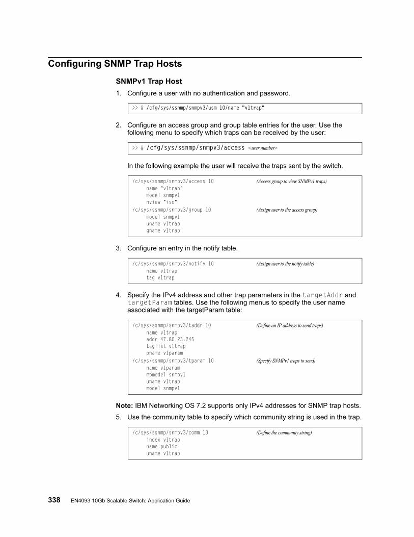
338 EN4093 10Gb Scalable Switch: Application Guide
Configuring SNMP Trap Hosts
SNMPv1 Trap Host
1. Configure a user with no authentication and password.
2. Configure an access group and group table entries for the user. Use the following menu to specify which traps can be received by the user:
In the following example the user will receive the traps sent by the switch.
3. Configure an entry in the notify table.
4. Specify the IPv4 address and other trap parameters in the targetAddr and targetParam tables. Use the following menus to specify the user name associated with the targetParam table:
Note: IBM Networking OS 7.2 supports only IPv4 addresses for SNMP trap hosts.
5. Use the community table to specify which community string is used in the trap.
>> # /cfg/sys/ssnmp/snmpv3/usm 10/name "v1trap"
>> # /cfg/sys/ssnmp/snmpv3/access <user number>
/c/sys/ssnmp/snmpv3/access 10 (Access group to view SNMPv1 traps) name "v1trap" model snmpv1 nview "iso"/c/sys/ssnmp/snmpv3/group 10 (Assign user to the access group) model snmpv1 uname v1trap gname v1trap
/c/sys/ssnmp/snmpv3/notify 10 (Assign user to the notify table) name v1trap tag v1trap
/c/sys/ssnmp/snmpv3/taddr 10 (Define an IP address to send traps) name v1trap addr 47.80.23.245 taglist v1trap pname v1param/c/sys/ssnmp/snmpv3/tparam 10 (Specify SNMPv1 traps to send) name v1param mpmodel snmpv1 uname v1trap model snmpv1
/c/sys/ssnmp/snmpv3/comm 10 (Define the community string) index v1trap name public uname v1trap
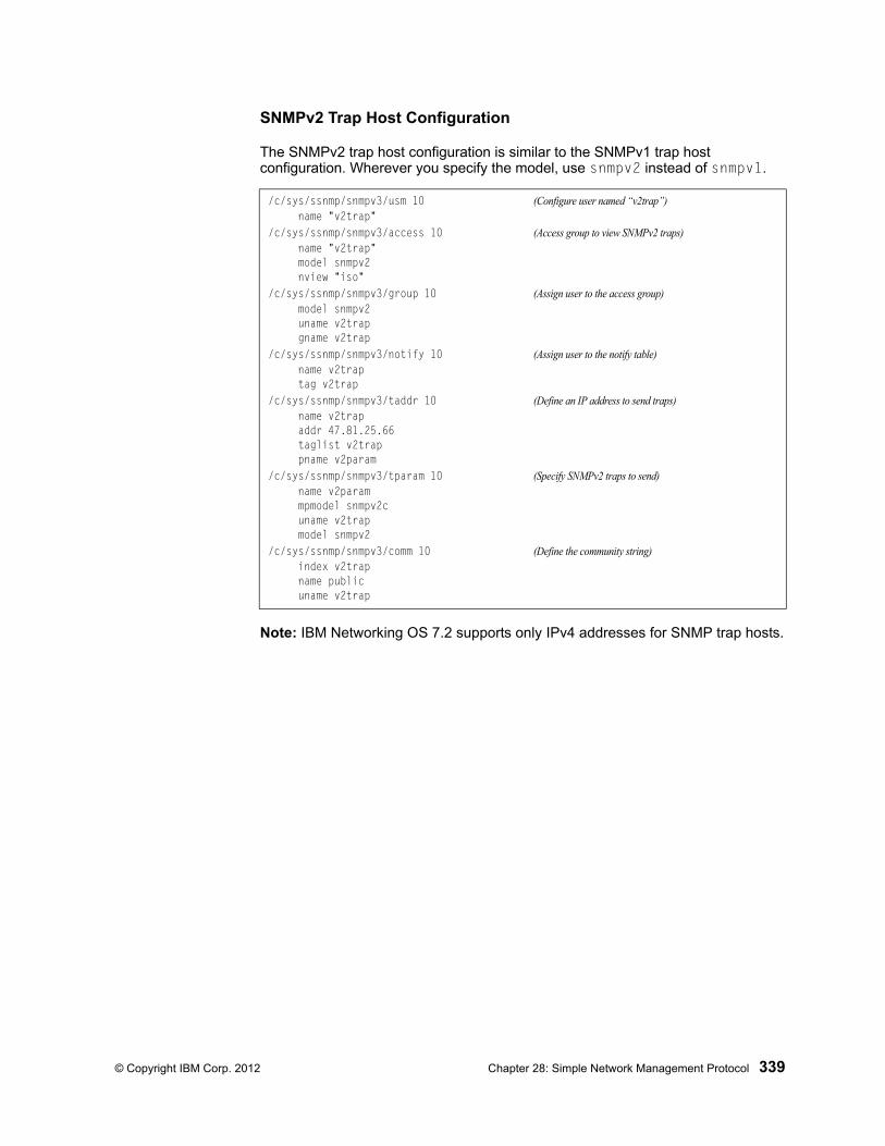
© Copyright IBM Corp. 2012 Chapter 28: Simple Network Management Protocol 339
SNMPv2 Trap Host Configuration
The SNMPv2 trap host configuration is similar to the SNMPv1 trap host configuration. Wherever you specify the model, use snmpv2 instead of snmpv1.
Note: IBM Networking OS 7.2 supports only IPv4 addresses for SNMP trap hosts.
/c/sys/ssnmp/snmpv3/usm 10 (Configure user named “v2trap”) name "v2trap"/c/sys/ssnmp/snmpv3/access 10 (Access group to view SNMPv2 traps) name "v2trap" model snmpv2 nview "iso"/c/sys/ssnmp/snmpv3/group 10 (Assign user to the access group) model snmpv2 uname v2trap gname v2trap/c/sys/ssnmp/snmpv3/notify 10 (Assign user to the notify table) name v2trap tag v2trap/c/sys/ssnmp/snmpv3/taddr 10 (Define an IP address to send traps) name v2trap addr 47.81.25.66 taglist v2trap pname v2param/c/sys/ssnmp/snmpv3/tparam 10 (Specify SNMPv2 traps to send) name v2param mpmodel snmpv2c uname v2trap model snmpv2/c/sys/ssnmp/snmpv3/comm 10 (Define the community string) index v2trap name public uname v2trap
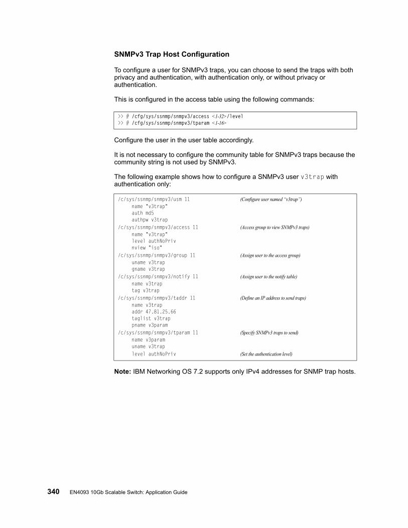
340 EN4093 10Gb Scalable Switch: Application Guide
SNMPv3 Trap Host Configuration
To configure a user for SNMPv3 traps, you can choose to send the traps with both privacy and authentication, with authentication only, or without privacy or authentication.
This is configured in the access table using the following commands:
Configure the user in the user table accordingly.
It is not necessary to configure the community table for SNMPv3 traps because the community string is not used by SNMPv3.
The following example shows how to configure a SNMPv3 user v3trap with authentication only:
Note: IBM Networking OS 7.2 supports only IPv4 addresses for SNMP trap hosts.
>> # /cfg/sys/ssnmp/snmpv3/access <1-32>/level>> # /cfg/sys/ssnmp/snmpv3/tparam <1-16>
/c/sys/ssnmp/snmpv3/usm 11 (Configure user named “v3trap”) name "v3trap" auth md5 authpw v3trap/c/sys/ssnmp/snmpv3/access 11 (Access group to view SNMPv3 traps) name "v3trap" level authNoPriv nview "iso"/c/sys/ssnmp/snmpv3/group 11 (Assign user to the access group) uname v3trap gname v3trap/c/sys/ssnmp/snmpv3/notify 11 (Assign user to the notify table) name v3trap tag v3trap/c/sys/ssnmp/snmpv3/taddr 11 (Define an IP address to send traps) name v3trap addr 47.81.25.66 taglist v3trap pname v3param/c/sys/ssnmp/snmpv3/tparam 11 (Specify SNMPv3 traps to send) name v3param uname v3trap level authNoPriv (Set the authentication level)
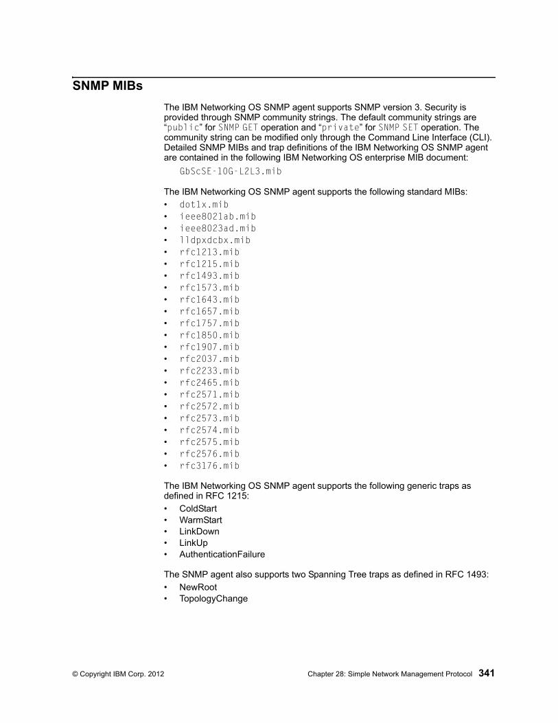
© Copyright IBM Corp. 2012 Chapter 28: Simple Network Management Protocol 341
SNMP MIBs
The IBM Networking OS SNMP agent supports SNMP version 3. Security is provided through SNMP community strings. The default community strings are “public” for SNMP GET operation and “private” for SNMP SET operation. The community string can be modified only through the Command Line Interface (CLI). Detailed SNMP MIBs and trap definitions of the IBM Networking OS SNMP agent are contained in the following IBM Networking OS enterprise MIB document:
GbScSE-10G-L2L3.mib
The IBM Networking OS SNMP agent supports the following standard MIBs:
• dot1x.mib• ieee8021ab.mib• ieee8023ad.mib• lldpxdcbx.mib• rfc1213.mib• rfc1215.mib• rfc1493.mib• rfc1573.mib• rfc1643.mib• rfc1657.mib• rfc1757.mib• rfc1850.mib• rfc1907.mib• rfc2037.mib• rfc2233.mib• rfc2465.mib• rfc2571.mib• rfc2572.mib• rfc2573.mib• rfc2574.mib• rfc2575.mib• rfc2576.mib• rfc3176.mib
The IBM Networking OS SNMP agent supports the following generic traps as defined in RFC 1215:
• ColdStart• WarmStart• LinkDown• LinkUp• AuthenticationFailure
The SNMP agent also supports two Spanning Tree traps as defined in RFC 1493:
• NewRoot• TopologyChange
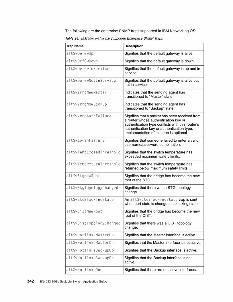
342 EN4093 10Gb Scalable Switch: Application Guide
The following are the enterprise SNMP traps supported in IBM Networking OS:
Table 24. IBM Networking OS-Supported Enterprise SNMP Traps
Trap Name Description
altSwDefGwUp Signifies that the default gateway is alive.
altSwDefGwDown Signifies that the default gateway is down.
altSwDefGwInService Signifies that the default gateway is up and in service
altSwDefGwNotInService Signifies that the default gateway is alive but not in service
altSwVrrpNewMaster Indicates that the sending agent has transitioned to “Master” state.
altSwVrrpNewBackup Indicates that the sending agent has transitioned to “Backup” state.
altSwVrrpAuthFailure Signifies that a packet has been received from a router whose authentication key or authentication type conflicts with this router's authentication key or authentication type. Implementation of this trap is optional.
altSwLoginFailure Signifies that someone failed to enter a valid username/password combination.
altSwTempExceedThreshold Signifies that the switch temperature has exceeded maximum safety limits.
altSwTempReturnThreshold Signifies that the switch temperature has returned below maximum safety limits.
altSwStgNewRoot Signifies that the bridge has become the new root of the STG.
altSwStgTopologyChanged Signifies that there was a STG topology change.
altSwStgBlockingState An altSwStgBlockingState trap is sent when port state is changed in blocking state.
altSwCistNewRoot Signifies that the bridge has become the new root of the CIST.
altSwCistTopologyChanged Signifies that there was a CIST topology change.
altSwHotlinksMasterUp Signifies that the Master interface is active.
altSwHotlinksMasterDn Signifies that the Master interface is not active.
altSwHotlinksBackupUp Signifies that the Backup interface is active.
altSwHotlinksBackupDn Signifies that the Backup interface is not active.
altSwHotlinksNone Signifies that there are no active interfaces.
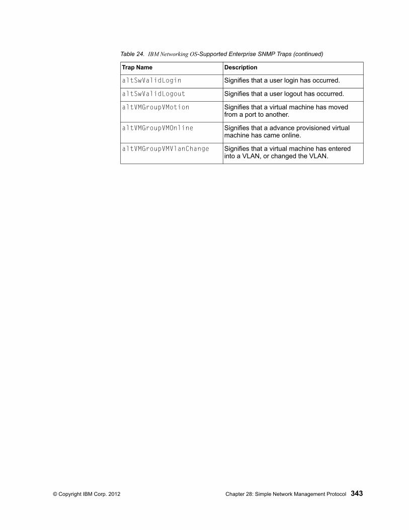
© Copyright IBM Corp. 2012 Chapter 28: Simple Network Management Protocol 343
altSwValidLogin Signifies that a user login has occurred.
altSwValidLogout Signifies that a user logout has occurred.
altVMGroupVMotion Signifies that a virtual machine has moved from a port to another.
altVMGroupVMOnline Signifies that a advance provisioned virtual machine has came online.
altVMGroupVMVlanChange Signifies that a virtual machine has entered into a VLAN, or changed the VLAN.
Table 24. IBM Networking OS-Supported Enterprise SNMP Traps (continued)
Trap Name Description
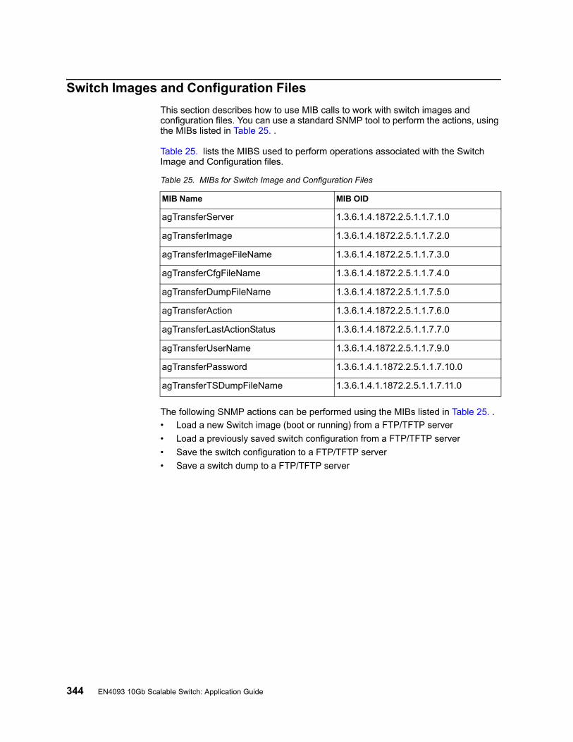
344 EN4093 10Gb Scalable Switch: Application Guide
Switch Images and Configuration Files
This section describes how to use MIB calls to work with switch images and configuration files. You can use a standard SNMP tool to perform the actions, using the MIBs listed in Table 25. .
Table 25. lists the MIBS used to perform operations associated with the Switch Image and Configuration files.
The following SNMP actions can be performed using the MIBs listed in Table 25. .
• Load a new Switch image (boot or running) from a FTP/TFTP server
• Load a previously saved switch configuration from a FTP/TFTP server
• Save the switch configuration to a FTP/TFTP server
• Save a switch dump to a FTP/TFTP server
Table 25. MIBs for Switch Image and Configuration Files
MIB Name MIB OID
agTransferServer 1.3.6.1.4.1872.2.5.1.1.7.1.0
agTransferImage 1.3.6.1.4.1872.2.5.1.1.7.2.0
agTransferImageFileName 1.3.6.1.4.1872.2.5.1.1.7.3.0
agTransferCfgFileName 1.3.6.1.4.1872.2.5.1.1.7.4.0
agTransferDumpFileName 1.3.6.1.4.1872.2.5.1.1.7.5.0
agTransferAction 1.3.6.1.4.1872.2.5.1.1.7.6.0
agTransferLastActionStatus 1.3.6.1.4.1872.2.5.1.1.7.7.0
agTransferUserName 1.3.6.1.4.1872.2.5.1.1.7.9.0
agTransferPassword 1.3.6.1.4.1.1872.2.5.1.1.7.10.0
agTransferTSDumpFileName 1.3.6.1.4.1.1872.2.5.1.1.7.11.0

© Copyright IBM Corp. 2012 Chapter 28: Simple Network Management Protocol 345
Loading a New Switch Image
To load a new switch image with the name “MyNewImage-1.img” into image2, follow the steps below. This example shows an FTP/TFTP server at IPv4 address 192.168.10.10, though IPv6 is also supported.
1. Set the FTP/TFTP server address where the switch image resides:
Set agTransferServer.0 "192.168.10.10"
2. Set the area where the new image will be loaded:
Set agTransferImage.0 "image2"
3. Set the name of the image:
Set agTransferImageFileName.0 "MyNewImage-1.img"
4. If you are using an FTP server, enter a username:
Set agTransferUserName.0 "MyName"
5. If you are using an FTP server, enter a password:
Set agTransferPassword.0 "MyPassword"
6. Initiate the transfer. To transfer a switch image, enter 2 (gtimg):
Set agTransferAction.0 "2"
Loading a Saved Switch Configuration
To load a saved switch configuration with the name “MyRunningConfig.cfg” into the switch, follow the steps below. This example shows a TFTP server at IPv4 address 192.168.10.10, though IPv6 is also supported.
1. Set the FTP/TFTP server address where the switch Configuration File resides:
Set agTransferServer.0 "192.168.10.10"
2. Set the name of the configuration file:
Set agTransferCfgFileName.0 "MyRunningConfig.cfg"
3. If you are using an FTP server, enter a username:
Set agTransferUserName.0 "MyName"
4. If you are using an FTP server, enter a password:
Set agTransferPassword.0 "MyPassword"
5. Initiate the transfer. To restore a running configuration, enter 3:
Set agTransferAction.0 "3"
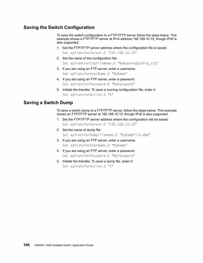
346 EN4093 10Gb Scalable Switch: Application Guide
Saving the Switch Configuration
To save the switch configuration to a FTP/TFTP server follow the steps below. This example shows a FTP/TFTP server at IPv4 address 192.168.10.10, though IPv6 is also supported.
1. Set the FTP/TFTP server address where the configuration file is saved:
Set agTransferServer.0 "192.168.10.10"
2. Set the name of the configuration file:
Set agTransferCfgFileName.0 "MyRunningConfig.cfg"
3. If you are using an FTP server, enter a username:
Set agTransferUserName.0 "MyName"
4. If you are using an FTP server, enter a password:
Set agTransferPassword.0 "MyPassword"
5. Initiate the transfer. To save a running configuration file, enter 4:
Set agTransferAction.0 "4"
Saving a Switch Dump
To save a switch dump to a FTP/TFTP server, follow the steps below. This example shows an FTP/TFTP server at 192.168.10.10, though IPv6 is also supported.
1. Set the FTP/TFTP server address where the configuration will be saved:
Set agTransferServer.0 "192.168.10.10"
2. Set the name of dump file:
Set agTransferDumpFileName.0 "MyDumpFile.dmp"
3. If you are using an FTP server, enter a username:
Set agTransferUserName.0 "MyName"
4. If you are using an FTP server, enter a password:
Set agTransferPassword.0 "MyPassword"
5. Initiate the transfer. To save a dump file, enter 5:
Set agTransferAction.0 "5"

© Copyright IBM Corp. 2012 347
Part 8: MonitoringThe ability to monitor traffic passing through the EN4093 can be invaluable for troubleshooting some types of networking problems. This sections cover the following monitoring features:
• Remote Monitoring (RMON)
• sFLOW
• Port Mirroring

348 EN4093 10Gb Scalable Switch: Application Guide
© Copyright IBM Corp. 2012 349
Chapter 29. Remote Monitoring
Remote Monitoring (RMON) allows network devices to exchange network monitoring data.
RMON performs the following major functions:
• Gathers cumulative statistics for Ethernet interfaces
• Tracks a history of statistics for Ethernet interfaces
• Creates and triggers alarms for user-defined events
RMON Overview
The RMON MIB provides an interface between the RMON agent on the switch and an RMON management application. The RMON MIB is described in RFC 1757.
The RMON standard defines objects that are suitable for the management of Ethernet networks. The RMON agent continuously collects statistics and proactively monitors switch performance. RMON allows you to monitor traffic flowing through the switch.
The switch supports the following RMON Groups, as described in RFC 1757:
• RMON Group 1–Statistics
• RMON Group 2–History
• RMON Group 3–Alarms
• RMON Group 9–Events
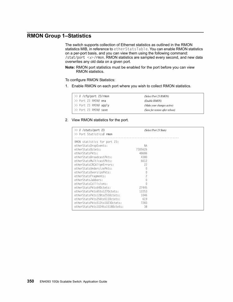
350 EN4093 10Gb Scalable Switch: Application Guide
RMON Group 1–Statistics
The switch supports collection of Ethernet statistics as outlined in the RMON statistics MIB, in reference to etherStatsTable. You can enable RMON statistics on a per-port basis, and you can view them using the following command: /stat/port <x>/rmon. RMON statistics are sampled every second, and new data overwrites any old data on a given port.
Note: RMON port statistics must be enabled for the port before you can view RMON statistics.
To configure RMON Statistics:
1. Enable RMON on each port where you wish to collect RMON statistics.
2. View RMON statistics for the port.
>> # /cfg/port 23/rmon (Select Port 23 RMON)
>> Port 23 RMON# ena (Enable RMON)
>> Port 23 RMON# apply (Make your changes active)
>> Port 23 RMON# save (Save for restore after reboot)
>> # /stats/port 23 (Select Port 23 Stats)>> Port Statistics# rmon------------------------------------------------------------------RMON statistics for port 23:etherStatsDropEvents: NAetherStatsOctets: 7305626etherStatsPkts: 48686etherStatsBroadcastPkts: 4380etherStatsMulticastPkts: 6612etherStatsCRCAlignErrors: 22etherStatsUndersizePkts: 0etherStatsOversizePkts: 0etherStatsFragments: 2etherStatsJabbers: 0etherStatsCollisions: 0etherStatsPkts64Octets: 27445etherStatsPkts65to127Octets: 12253etherStatsPkts128to255Octets: 1046etherStatsPkts256to511Octets: 619etherStatsPkts512to1023Octets: 7283etherStatsPkts1024to1518Octets: 38
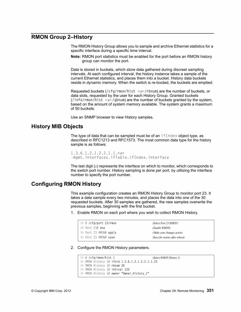
© Copyright IBM Corp. 2012 Chapter 29: Remote Monitoring 351
RMON Group 2–History
The RMON History Group allows you to sample and archive Ethernet statistics for a specific interface during a specific time interval.
Note: RMON port statistics must be enabled for the port before an RMON history group can monitor the port.
Data is stored in buckets, which store data gathered during discreet sampling intervals. At each configured interval, the history instance takes a sample of the current Ethernet statistics, and places them into a bucket. History data buckets reside in dynamic memory. When the switch is re-booted, the buckets are emptied.
Requested buckets (/cfg/rmon/hist <x>/rbnum) are the number of buckets, or data slots, requested by the user for each History Group. Granted buckets (/info/rmon/hist <x>/gbnum) are the number of buckets granted by the system, based on the amount of system memory available. The system grants a maximum of 50 buckets.
Use an SNMP browser to view History samples.
History MIB Objects
The type of data that can be sampled must be of an ifIndex object type, as described in RFC1213 and RFC1573. The most common data type for the history sample is as follows:
1.3.6.1.2.1.2.2.1.1.<x> -mgmt.interfaces.ifTable.ifIndex.interface
The last digit (x) represents the interface on which to monitor, which corresponds to the switch port number. History sampling is done per port, by utilizing the interface number to specify the port number.
Configuring RMON History
This example configuration creates an RMON History Group to monitor port 23. It takes a data sample every two minutes, and places the data into one of the 30 requested buckets. After 30 samples are gathered, the new samples overwrite the previous samples, beginning with the first bucket.
1. Enable RMON on each port where you wish to collect RMON History.
2. Configure the RMON History parameters.
>> # /cfg/port 23/rmon (Select Port 23 RMON)>> Port 23# ena (Enable RMON)
>> Port 23 RMON# apply (Make your changes active)
>> Port 23 RMON# save (Save for restore after reboot)
>> # /cfg/rmon/hist 1 (Select RMON History 1)>> RMON History 1# ifoid 1.3.6.1.2.1.2.2.1.1.23 >> RMON History 1# rbnum 30 >> RMON History 1# intrval 120 >> RMON History 1# owner "Owner_History_1"

352 EN4093 10Gb Scalable Switch: Application Guide
3. Apply and save the configuration.
Use SNMP to view the data.
>> RMON History 1# apply (Make your changes active)
>> RMON History 1# save (Save for restore after reboot)

© Copyright IBM Corp. 2012 Chapter 29: Remote Monitoring 353
RMON Group 3–Alarms
The RMON Alarm Group allows you to define a set of thresholds used to determine network performance. When a configured threshold is crossed, an alarm is generated. For example, you can configure the switch to issue an alarm if more than 1,000 CRC errors occur during a 10-minute time interval.
Each Alarm index consists of a variable to monitor, a sampling time interval, and parameters for rising and falling thresholds. The Alarm group can be used to track rising or falling values for a MIB object. The object must be a counter, gauge, integer, or time interval.
Use the /cfg/rmon/alarm <x>/revtidx command or the /cfg/rmon/alarm <x>/fevtidx command to correlate an alarm index to an event index. When the alarm threshold is reached, the corresponding event is triggered.
Alarm MIB Objects
The most common data types used for alarm monitoring are ifStats: errors, drops, bad CRCs, and so on. These MIB Object Identifiers (OIDs) correlate to the ones tracked by the History group. An example of an ICMP stat is as follows:
1.3.6.1.2.1.5.1.<x> - mgmt.icmp.icmpInMsgs
where x represents the interface on which to monitor, which corresponds to the switch interface number or port number, as follows:
• 1 through 128 = Switch interface number
• 129 = Switch port 1
• 130 = Switch port 2
• 131 = Switch port 3, and so on.
This value represents the alarm's MIB OID, as a string. Note that for non-tables, you must supply a .0 to specify an end node.
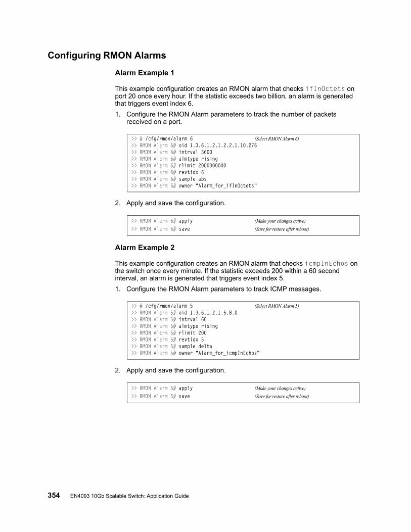
354 EN4093 10Gb Scalable Switch: Application Guide
Configuring RMON Alarms
Alarm Example 1
This example configuration creates an RMON alarm that checks ifInOctets on port 20 once every hour. If the statistic exceeds two billion, an alarm is generated that triggers event index 6.
1. Configure the RMON Alarm parameters to track the number of packets received on a port.
2. Apply and save the configuration.
Alarm Example 2
This example configuration creates an RMON alarm that checks icmpInEchos on the switch once every minute. If the statistic exceeds 200 within a 60 second interval, an alarm is generated that triggers event index 5.
1. Configure the RMON Alarm parameters to track ICMP messages.
2. Apply and save the configuration.
>> # /cfg/rmon/alarm 6 (Select RMON Alarm 6)>> RMON Alarm 6# oid 1.3.6.1.2.1.2.2.1.10.276>> RMON Alarm 6# intrval 3600>> RMON Alarm 6# almtype rising>> RMON Alarm 6# rlimit 2000000000>> RMON Alarm 6# revtidx 6>> RMON Alarm 6# sample abs>> RMON Alarm 6# owner "Alarm_for_ifInOctets"
>> RMON Alarm 6# apply (Make your changes active)
>> RMON Alarm 6# save (Save for restore after reboot)
>> # /cfg/rmon/alarm 5 (Select RMON Alarm 5)>> RMON Alarm 5# oid 1.3.6.1.2.1.5.8.0>> RMON Alarm 5# intrval 60>> RMON Alarm 5# almtype rising>> RMON Alarm 5# rlimit 200>> RMON Alarm 5# revtidx 5>> RMON Alarm 5# sample delta>> RMON Alarm 5# owner "Alarm_for_icmpInEchos"
>> RMON Alarm 5# apply (Make your changes active)
>> RMON Alarm 5# save (Save for restore after reboot)
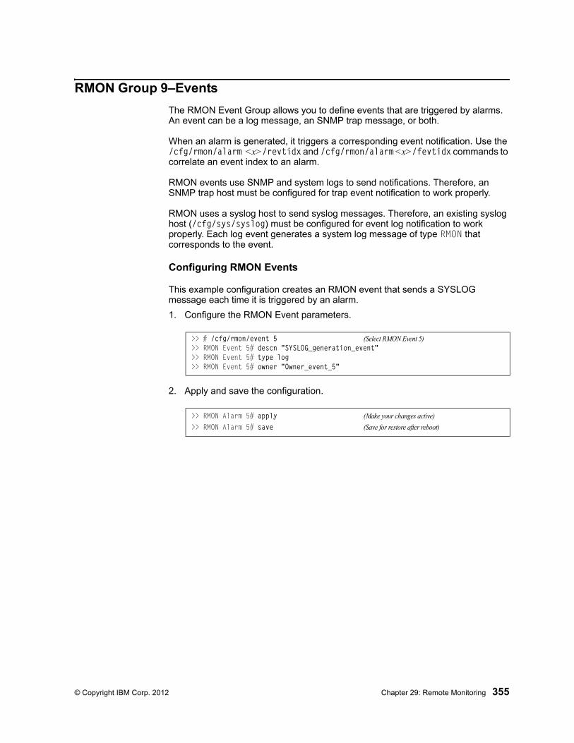
© Copyright IBM Corp. 2012 Chapter 29: Remote Monitoring 355
RMON Group 9–Events
The RMON Event Group allows you to define events that are triggered by alarms. An event can be a log message, an SNMP trap message, or both.
When an alarm is generated, it triggers a corresponding event notification. Use the /cfg/rmon/alarm <x>/revtidx and /cfg/rmon/alarm <x>/fevtidx commands to correlate an event index to an alarm.
RMON events use SNMP and system logs to send notifications. Therefore, an SNMP trap host must be configured for trap event notification to work properly.
RMON uses a syslog host to send syslog messages. Therefore, an existing syslog host (/cfg/sys/syslog) must be configured for event log notification to work properly. Each log event generates a system log message of type RMON that corresponds to the event.
Configuring RMON Events
This example configuration creates an RMON event that sends a SYSLOG message each time it is triggered by an alarm.
1. Configure the RMON Event parameters.
2. Apply and save the configuration.
>> # /cfg/rmon/event 5 (Select RMON Event 5)>> RMON Event 5# descn "SYSLOG_generation_event">> RMON Event 5# type log >> RMON Event 5# owner "Owner_event_5"
>> RMON Alarm 5# apply (Make your changes active)
>> RMON Alarm 5# save (Save for restore after reboot)

356 EN4093 10Gb Scalable Switch: Application Guide
© Copyright IBM Corp. 2012 357
Chapter 30. sFLOW
The EN4093 supports sFlow technology for monitoring traffic in data networks. The switch includes an embedded sFlow agent which can be configured to sample network traffic and provide continuous monitoring information of IPv4 traffic to a central sFlow analyzer.
The switch is responsible only for forwarding sFlow information. A separate sFlow analyzer is required elsewhere on the network in order to interpret sFlow data.
Note: IBM Networking OS 7.2 does not support IPv6 for sFLOW.
sFlow Statistical CountersThe EN4093 can be configured to send network statistics to an sFlow analyzer at regular intervals. For each port, a polling interval of 5 to 60 seconds can be configured, or 0 (the default) to disable this feature.
When polling is enabled, at the end of each configured polling interval, the EN4093 reports general port statistics (as found in the output of the /stats/port <x>/if command) and port Ethernet statistics (as found in the output of the /stats/port <x>/ether command).
sFlow Network SamplingIn addition to statistical counters, the EN4093 can be configured to collect periodic samples of the traffic data received on each port. For each sample, 128 bytes are copied, UDP-encapsulated, and sent to the configured sFlow analyzer.
For each port, the sFlow sampling rate can be configured to occur once each 256 to 65536 packets, or 0 to disable (the default). A sampling rate of 256 means that one sample will be taken for approximately every 256 packets received on the port. The sampling rate is statistical, however. It is possible to have slightly more or fewer samples sent to the analyzer for any specific group of packets (especially under low traffic conditions). The actual sample rate becomes most accurate over time, and under higher traffic flow.
sFlow sampling has the following restrictions:
• Sample Rate—The fastest sFlow sample rate is 1 out of every 256 packets.
• ACLs—sFlow sampling is performed before ACLs are processed. For ports configured both with sFlow sampling and one or more ACLs, sampling will occur regardless of the action of the ACL.
• Port Mirroring—sFlow sampling will not occur on mirrored traffic. If sFlow sampling is enabled on a port that is configured as a port monitor, the mirrored traffic will not be sampled.
Note: Although sFlow sampling is not generally a CPU-intensive operation, configuring fast sampling rates (such as once every 256 packets) on ports under heavy traffic loads can cause switch CPU utilization to reach maximum. Use larger rate values for ports that experience heavy traffic.

358 EN4093 10Gb Scalable Switch: Application Guide
sFlow Example Configuration
1. Specify the location of the sFlow analyzer (the server and optional port to which the sFlow information will be sent):
By default, the switch uses established sFlow service port 6343.
To disable sFlow features across all ports, use the following command: /cfg/sys/sflow/dis
2. On a per-port basis, define the statistics polling rate:
Specify a polling rate between 5 and 60 seconds, or 0 to disable. By default, polling is 0 (disabled) for each port.
3. On a per-port basis, define the data sampling rate:
Specify a sampling rate between 256 and 65536 packets, or 0 to disable. By default, the sampling rate is 0 (disabled) for each port.
4. Apply and save the configuration.
>> # /cfg/sys/sflow/saddress <IPv4 address> (sFlow server address)>> sFlow# sport <service port> (Set the optional service port)>> sFlow# ena (Enable sFlow features)
>> sFlow# port <port number> (Select the port)>> sFlow Port# polling <polling rate> (Statistics polling rate)
>> sFlow Port# sampling <sampling rate> (Data sampling rate)
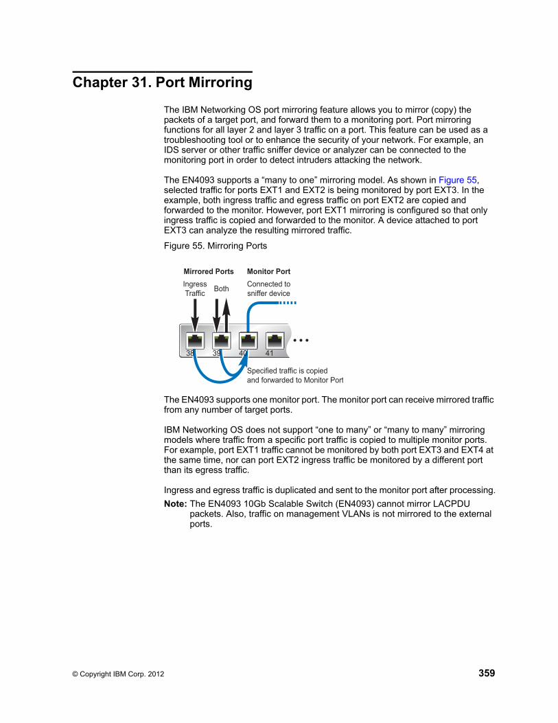
© Copyright IBM Corp. 2012 359
Chapter 31. Port Mirroring
The IBM Networking OS port mirroring feature allows you to mirror (copy) the packets of a target port, and forward them to a monitoring port. Port mirroring functions for all layer 2 and layer 3 traffic on a port. This feature can be used as a troubleshooting tool or to enhance the security of your network. For example, an IDS server or other traffic sniffer device or analyzer can be connected to the monitoring port in order to detect intruders attacking the network.
The EN4093 supports a “many to one” mirroring model. As shown in Figure 55, selected traffic for ports EXT1 and EXT2 is being monitored by port EXT3. In the example, both ingress traffic and egress traffic on port EXT2 are copied and forwarded to the monitor. However, port EXT1 mirroring is configured so that only ingress traffic is copied and forwarded to the monitor. A device attached to port EXT3 can analyze the resulting mirrored traffic.
Figure 55. Mirroring Ports
The EN4093 supports one monitor port. The monitor port can receive mirrored traffic from any number of target ports.
IBM Networking OS does not support “one to many” or “many to many” mirroring models where traffic from a specific port traffic is copied to multiple monitor ports. For example, port EXT1 traffic cannot be monitored by both port EXT3 and EXT4 at the same time, nor can port EXT2 ingress traffic be monitored by a different port than its egress traffic.
Ingress and egress traffic is duplicated and sent to the monitor port after processing.
Note: The EN4093 10Gb Scalable Switch (EN4093) cannot mirror LACPDU packets. Also, traffic on management VLANs is not mirrored to the external ports.
Monitor Port
Specified traffic is copiedand forwarded to Monitor Port
Mirrored Ports
IngressTraffic
BothConnected tosniffer device
38 39 40 41
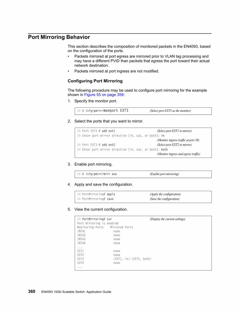
360 EN4093 10Gb Scalable Switch: Application Guide
Port Mirroring Behavior
This section describes the composition of monitored packets in the EN4093, based on the configuration of the ports.
• Packets mirrored at port egress are mirrored prior to VLAN tag processing and may have a different PVID than packets that egress the port toward their actual network destination.
• Packets mirrored at port ingress are not modified.
Configuring Port Mirroring
The following procedure may be used to configure port mirroring for the example shown in Figure 55 on page 359:
1. Specify the monitor port.
2. Select the ports that you want to mirror.
3. Enable port mirroring.
4. Apply and save the configuration.
5. View the current configuration.
>> # /cfg/pmirr/monport EXT3 (Select port EXT3 as the monitor)
>> Port EXT3 # add ext1 (Select port EXT1 to mirror)>> Enter port mirror direction [in, out, or both]: in
(Monitor ingress traffic at port 38)>> Port EXT3 # add ext2 (Select port EXT2 to mirror)>> Enter port mirror direction [in, out, or both]: both
(Monitor ingress and egress traffic)
>> # /cfg/pmirr/mirr ena (Enable port mirroring)
>> PortMirroring# apply (Apply the configuration)>> PortMirroring# save (Save the configuration)
>> PortMirroring# cur (Display the current settings)Port mirroring is enabledMonitoring Ports Mirrored PortsINTA1 noneINTA2 noneINTA3 noneINTA4 none...EXT1 noneEXT2 noneEXT3 (EXT1, in) (EXT2, both)EXT4 none...

© Copyright IBM Corp. 2012 361
Part 9: Appendices

362 EN4093 10Gb Scalable Switch: Application Guide
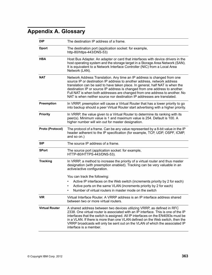
© Copyright IBM Corp. 2012 363
Appendix A. Glossary
DIP The destination IP address of a frame.
Dport The destination port (application socket: for example, http-80/https-443/DNS-53)
HBA Host Bus Adapter. An adapter or card that interfaces with device drivers in the host operating system and the storage target in a Storage Area Network (SAN). It is equivalent to a Network Interface Controller (NIC) from a Local Area Network (LAN).
NAT Network Address Translation. Any time an IP address is changed from one source IP or destination IP address to another address, network address translation can be said to have taken place. In general, half NAT is when the destination IP or source IP address is changed from one address to another. Full NAT is when both addresses are changed from one address to another. No NAT is when neither source nor destination IP addresses are translated.
Preemption In VRRP, preemption will cause a Virtual Router that has a lower priority to go into backup should a peer Virtual Router start advertising with a higher priority.
Priority In VRRP, the value given to a Virtual Router to determine its ranking with its peer(s). Minimum value is 1 and maximum value is 254. Default is 100. A higher number will win out for master designation.
Proto (Protocol) The protocol of a frame. Can be any value represented by a 8-bit value in the IP header adherent to the IP specification (for example, TCP, UDP, OSPF, ICMP, and so on.)
SIP The source IP address of a frame.
SPort The source port (application socket: for example, HTTP-80/HTTPS-443/DNS-53).
Tracking In VRRP, a method to increase the priority of a virtual router and thus master designation (with preemption enabled). Tracking can be very valuable in an active/active configuration.
You can track the following:
• Active IP interfaces on the Web switch (increments priority by 2 for each)• Active ports on the same VLAN (increments priority by 2 for each)• Number of virtual routers in master mode on the switch
VIR Virtual Interface Router. A VRRP address is an IP interface address shared between two or more virtual routers.
Virtual Router A shared address between two devices utilizing VRRP, as defined in RFC 2338. One virtual router is associated with an IP interface. This is one of the IP interfaces that the switch is assigned. All IP interfaces on the EN4093s must be in a VLAN. If there is more than one VLAN defined on the Web switch, then the VRRP broadcasts will only be sent out on the VLAN of which the associated IP interface is a member.
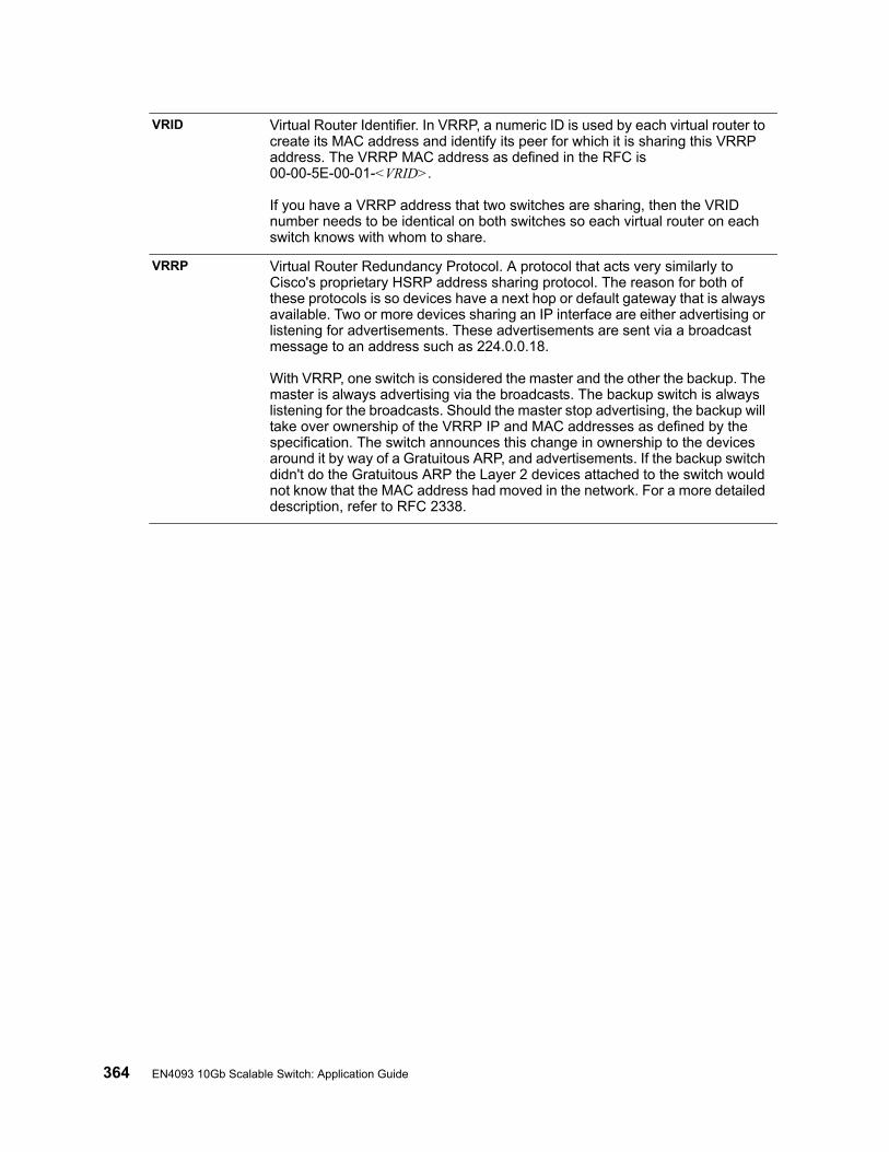
364 EN4093 10Gb Scalable Switch: Application Guide
VRID Virtual Router Identifier. In VRRP, a numeric ID is used by each virtual router to create its MAC address and identify its peer for which it is sharing this VRRP address. The VRRP MAC address as defined in the RFC is 00-00-5E-00-01-<VRID>.
If you have a VRRP address that two switches are sharing, then the VRID number needs to be identical on both switches so each virtual router on each switch knows with whom to share.
VRRP Virtual Router Redundancy Protocol. A protocol that acts very similarly to Cisco's proprietary HSRP address sharing protocol. The reason for both of these protocols is so devices have a next hop or default gateway that is always available. Two or more devices sharing an IP interface are either advertising or listening for advertisements. These advertisements are sent via a broadcast message to an address such as 224.0.0.18.
With VRRP, one switch is considered the master and the other the backup. The master is always advertising via the broadcasts. The backup switch is always listening for the broadcasts. Should the master stop advertising, the backup will take over ownership of the VRRP IP and MAC addresses as defined by the specification. The switch announces this change in ownership to the devices around it by way of a Gratuitous ARP, and advertisements. If the backup switch didn't do the Gratuitous ARP the Layer 2 devices attached to the switch would not know that the MAC address had moved in the network. For a more detailed description, refer to RFC 2338.

© Copyright IBM Corp. 2012 365
Appendix B. Getting help and technical assistance
If you need help, service, or technical assistance or just want more information about IBM products, you will find a wide variety of sources available from IBM to assist you. This section contains information about where to go for additional information about IBM and IBM products, what to do if you experience a problem with your system, and whom to call for service, if it is necessary.
Before you call
Before you call, make sure that you have taken these steps to try to solve the problem yourself:
• Check all cables to make sure that they are connected.
• Check the power switches to make sure that the system and any optional devices are turned on.
• Use the troubleshooting information in your system documentation, and use the diagnostic tools that come with your system. Information about diagnostic tools is in the Problem Determination and Service Guide on the IBM Documentation CD that comes with your system.
• Go to the IBM support website at http://www.ibm.com/systems/support/ to check for technical information, hints, tips, and new device drivers or to submit a request for information.
You can solve many problems without outside assistance by following the troubleshooting procedures that IBM provides in the online help or in the documentation that is provided with your IBM product. The documentation that comes with IBM systems also describes the diagnostic tests that you can perform. Most systems, operating systems, and programs come with documentation that contains troubleshooting procedures and explanations of error messages and error codes. If you suspect a software problem, see the documentation for the operating system or program.
Using the documentation
Information about your IBM system and pre-installed software, if any, or optional device is available in the documentation that comes with the product. That documentation can include printed documents, online documents, ReadMe files, and Help files. See the troubleshooting information in your system documentation for instructions for using the diagnostic programs. The troubleshooting information or the diagnostic programs might tell you that you need additional or updated device drivers or other software. IBM maintains pages on the World Wide Web where you can get the latest technical information and download device drivers and updates. To access these pages, go to http://www.ibm.com/systems/support/ and follow the instructions. Also, some documents are available through the IBM Publications Center at http://www.ibm.com/shop/publications/order/.

366 EN4093 10Gb Scalable Switch: Application Guide
Getting help and information on the World Wide Web
On the World Wide Web, the IBM website has up-to-date information about IBM systems, optional devices, services, and support. The address for IBM System x® and xSeries® information is http://www.ibm.com/systems/x/. The address for IBM Flex System information is http://www.ibm.com/systems/bladecenter/. The address for IBM IntelliStation® information is http://www.ibm.com/intellistation/.
You can find service information for IBM systems and optional devices at http://www.ibm.com/systems/support/.
Software service and support
Through IBM Support Line, you can get telephone assistance, for a fee, with usage, configuration, and software problems with System x and x Series servers, Flex System products, IntelliStation workstations, and appliances. For information about which products are supported by Support Line in your country or region, see http://www.ibm.com/services/sl/products/.
For more information about Support Line and other IBM services, see http://www.ibm.com/services/, or see http://www.ibm.com/planetwide/ for support telephone numbers. In the U.S. and Canada, call 1-800-IBM-SERV (1-800-426-7378).
Hardware service and support
You can receive hardware service through your IBM reseller or IBM Services. To locate a reseller authorized by IBM to provide warranty service, go to http://www.ibm.com/partnerworld/ and click Find Business Partners on the right side of the page. For IBM support telephone numbers, see http://www.ibm.com/planetwide/. In the U.S. and Canada, call 1-800-IBM-SERV (1-800-426-7378).
In the U.S. and Canada, hardware service and support is available 24 hours a day, 7 days a week. In the U.K., these services are available Monday through Friday, from 9 a.m. to 6 p.m.

© Copyright IBM Corp. 2012 Appendix B: Getting help and technical assistance 367
IBM Taiwan product service
IBM Taiwan product service contact information:
IBM Taiwan Corporation3F, No 7, Song Ren Rd.Taipei, TaiwanTelephone: 0800-016-888

368 EN4093 10Gb Scalable Switch: Application Guide

© Copyright IBM Corp. 2012 369
Appendix C. Notices
This information was developed for products and services offered in the U.S.A.
IBM may not offer the products, services, or features discussed in this document in other countries. Consult your local IBM representative for information on the products and services currently available in your area. Any reference to an IBM product, program, or service is not intended to state or imply that only that IBM product, program, or service may be used. Any functionally equivalent product, program, or service that does not infringe any IBM intellectual property right may be used instead. However, it is the user's responsibility to evaluate and verify the operation of any non-IBM product, program, or service.
IBM may have patents or pending patent applications covering subject matter described in this document. The furnishing of this document does not give you any license to these patents. You can send license inquiries, in writing, to:
IBM Director of LicensingIBM CorporationNorth Castle DriveArmonk, NY 10504-1785U.S.A.
INTERNATIONAL BUSINESS MACHINES CORPORATION PROVIDES THIS PUBLICATION “AS IS” WITHOUT WARRANTY OF ANY KIND, EITHER EXPRESS OR IMPLIED, INCLUDING, BUT NOT LIMITED TO, THE IMPLIED WARRANTIES OF NON-INFRINGEMENT, MERCHANTABILITY OR FITNESS FOR A PARTICULAR PURPOSE. Some states do not allow disclaimer of express or implied warranties in certain transactions, therefore, this statement may not apply to you.
This information could include technical inaccuracies or typographical errors. Changes are periodically made to the information herein; these changes will be incorporated in new editions of the publication. IBM may make improvements and/or changes in the product(s) and/or the program(s) described in this publication at any time without notice.
Any references in this information to non-IBM websites are provided for convenience only and do not in any manner serve as an endorsement of those websites. The materials at those websites are not part of the materials for this IBM product, and use of those websites is at your own risk.
IBM may use or distribute any of the information you supply in any way it believes appropriate without incurring any obligation to you.
370 EN4093 10Gb Scalable Switch: Application Guide
Trademarks
IBM, the IBM logo, and ibm.com are trademarks or registered trademarks of International Business Machines Corporation in the United States, other countries, or both. If these and other IBM trademarked terms are marked on their first occurrence in this information with a trademark symbol (® or ™), these symbols indicate U.S. registered or common law trademarks owned by IBM at the time this information was published. Such trademarks may also be registered or common law trademarks in other countries. A current list of IBM trademarks is available on the web at “Copyright and trademark information” at http://www.ibm.com/legal/copytrade.shtml.
Adobe and PostScript are either registered trademarks or trademarks of Adobe Systems Incorporated in the United States and/or other countries.
Cell Broadband Engine is a trademark of Sony Computer Entertainment, Inc., in the United States, other countries, or both and is used under license therefrom.
Intel, Intel Xeon, Itanium, and Pentium are trademarks or registered trademarks of Intel Corporation or its subsidiaries in the United States and other countries.
Java and all Java-based trademarks are trademarks of Sun Microsystems, Inc., in the United States, other countries, or both.
Linux is a registered trademark of Linus Torvalds in the United States, other countries, or both.
Microsoft, Windows, and Windows NT are trademarks of Microsoft Corporation in the United States, other countries, or both.
UNIX is a registered trademark of The Open Group in the United States and other countries.
Other company, product, or service names may be trademarks or service marks of others.

© Copyright IBM Corp. 2012 Appendix C: Notices 371
Important Notes
Processor speed indicates the internal clock speed of the microprocessor; other factors also affect application performance.
CD or DVD drive speed is the variable read rate. Actual speeds vary and are often less than the possible maximum.
When referring to processor storage, real and virtual storage, or channel volume, KB stands for 1024 bytes, MB stands for 1 048 576 bytes, and GB stands for 1 073 741 824 bytes.
When referring to hard disk drive capacity or communications volume, MB stands for 1 000 000 bytes, and GB stands for 1 000 000 000 bytes. Total user-accessible capacity can vary depending on operating environments.
Maximum internal hard disk drive capacities assume the replacement of any standard hard disk drives and population of all hard disk drive bays with the largest currently supported drives that are available from IBM.
Maximum memory might require replacement of the standard memory with an optional memory module.
IBM makes no representation or warranties regarding non-IBM products and services that are ServerProven, including but not limited to the implied warranties of merchantability and fitness for a particular purpose. These products are offered and warranted solely by third parties.
IBM makes no representations or warranties with respect to non-IBM products. Support (if any) for the non-IBM products is provided by the third party, not IBM.
Some software might differ from its retail version (if available) and might not include user manuals or all program functionality.
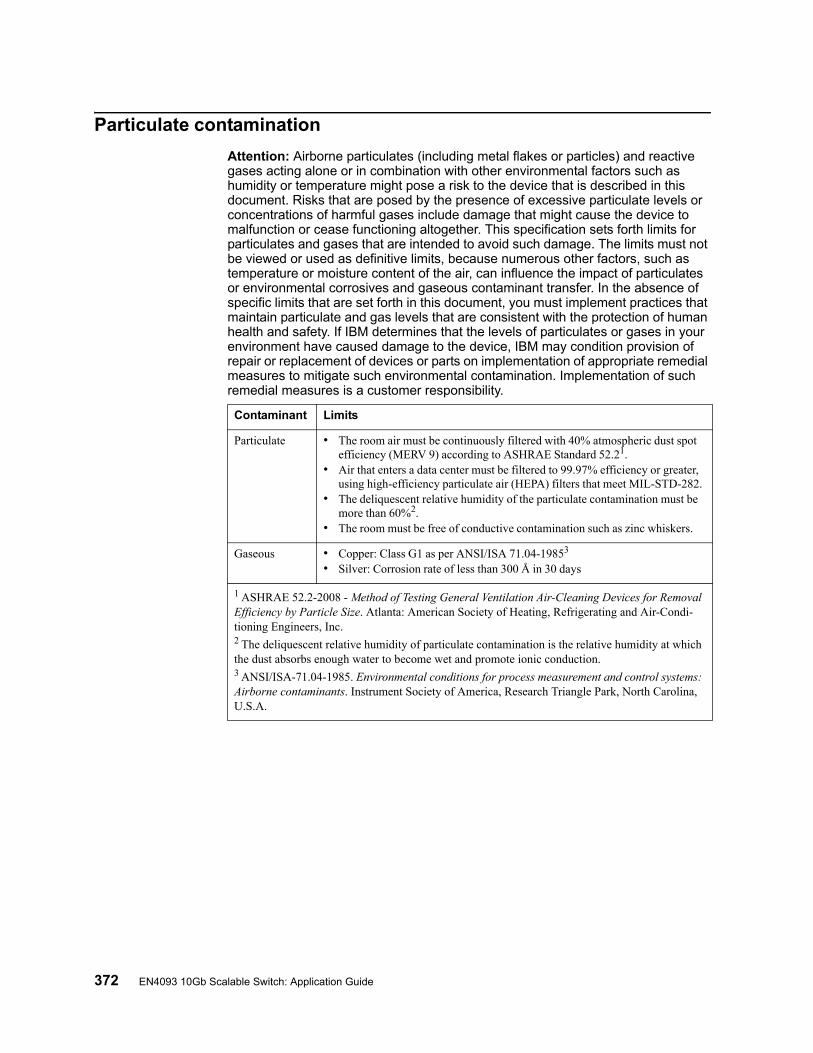
372 EN4093 10Gb Scalable Switch: Application Guide
Particulate contamination
Attention: Airborne particulates (including metal flakes or particles) and reactive gases acting alone or in combination with other environmental factors such as humidity or temperature might pose a risk to the device that is described in this document. Risks that are posed by the presence of excessive particulate levels or concentrations of harmful gases include damage that might cause the device to malfunction or cease functioning altogether. This specification sets forth limits for particulates and gases that are intended to avoid such damage. The limits must not be viewed or used as definitive limits, because numerous other factors, such as temperature or moisture content of the air, can influence the impact of particulates or environmental corrosives and gaseous contaminant transfer. In the absence of specific limits that are set forth in this document, you must implement practices that maintain particulate and gas levels that are consistent with the protection of human health and safety. If IBM determines that the levels of particulates or gases in your environment have caused damage to the device, IBM may condition provision of repair or replacement of devices or parts on implementation of appropriate remedial measures to mitigate such environmental contamination. Implementation of such remedial measures is a customer responsibility.
Contaminant Limits
Particulate • The room air must be continuously filtered with 40% atmospheric dust spot efficiency (MERV 9) according to ASHRAE Standard 52.21.
• Air that enters a data center must be filtered to 99.97% efficiency or greater, using high-efficiency particulate air (HEPA) filters that meet MIL-STD-282.
• The deliquescent relative humidity of the particulate contamination must be more than 60%2.
• The room must be free of conductive contamination such as zinc whiskers.
Gaseous • Copper: Class G1 as per ANSI/ISA 71.04-19853
• Silver: Corrosion rate of less than 300 Å in 30 days
1 ASHRAE 52.2-2008 - Method of Testing General Ventilation Air-Cleaning Devices for Removal Efficiency by Particle Size. Atlanta: American Society of Heating, Refrigerating and Air-Condi-tioning Engineers, Inc.2 The deliquescent relative humidity of particulate contamination is the relative humidity at which the dust absorbs enough water to become wet and promote ionic conduction.3 ANSI/ISA-71.04-1985. Environmental conditions for process measurement and control systems: Airborne contaminants. Instrument Society of America, Research Triangle Park, North Carolina, U.S.A.

© Copyright IBM Corp. 2012 Appendix C: Notices 373
Documentation format
The publications for this product are in Adobe Portable Document Format (PDF) and should be compliant with accessibility standards. If you experience difficulties when you use the PDF files and want to request a web-based format or accessible PDF document for a publication, direct your mail to the following address:
Information DevelopmentIBM Corporation205/A0153039 E. Cornwallis RoadP.O. Box 12195Research Triangle Park, North Carolina 27709-2195U.S.A.
In the request, be sure to include the publication part number and title.
When you send information to IBM, you grant IBM a non-exclusive right to use or distribute the information in any way it believes appropriate without incurring any obligation to you.

374 EN4093 10Gb Scalable Switch: Application Guide
Electronic emission notices
Federal Communications Commission (FCC) statement
Note: This equipment has been tested and found to comply with the limits for a Class A digital device, pursuant to Part 15 of the FCC Rules. These limits are designed to provide reasonable protection against harmful interference when the equipment is operated in a commercial environment. This equipment generates, uses, and can radiate radio frequency energy and, if not installed and used in accordance with the instruction manual, may cause harmful interference to radio communications. Operation of this equipment in a residential area is likely to cause harmful interference, in which case the user will be required to correct the interference at his own expense.
Properly shielded and grounded cables and connectors must be used in order to meet FCC emission limits. IBM is not responsible for any radio or television interference caused by using other than recommended cables and connectors or by unauthorized changes or modifications to this equipment. Unauthorized changes or modifications could void the user's authority to operate the equipment.
This device complies with Part 15 of the FCC Rules. Operation is subject to the following two conditions: (1) this device may not cause harmful interference, and (2) this device must accept any interference received, including interference that may cause undesired operation.
Industry Canada Class A emission compliance statement
This Class A digital apparatus complies with Canadian ICES-003.
Avis de conformité à la réglementation d'Industrie Canada
Cet appareil numérique de la classe A est conforme à la norme NMB-003 du Canada.
Australia and New Zealand Class A statement
Attention: This is a Class A product. In a domestic environment this product may cause radio interference in which case the user may be required to take adequate measures.
European Union EMC Directive conformance statement
This product is in conformity with the protection requirements of EU Council Directive 2004/108/EC on the approximation of the laws of the Member States relating to electromagnetic compatibility. IBM cannot accept responsibility for any failure to satisfy the protection requirements resulting from a nonrecommended modification of the product, including the fitting of non-IBM option cards.
Attention: This is an EN 55022 Class A product. In a domestic environment this product may cause radio interference in which case the user may be required to take adequate measures.

© Copyright IBM Corp. 2012 Appendix C: Notices 375
Responsible manufacturer:
International Business Machines Corp.New Orchard RoadArmonk, New York 10504914-499-1900
European Community contact:
IBM Technical Regulations, Department M456IBM-Allee 1, 71137 Ehningen, GermanyTelephone: +49 7032 15-2937E-mail: [email protected]
Germany Class A statement
Deutschsprachiger EU Hinweis:
Hinweis für Geräte der Klasse A EU-Richtlinie zur Elektromagnetischen Verträglichkeit
Dieses Produkt entspricht den Schutzanforderungen der EU-Richtlinie 2004/108/EG zur Angleichung der Rechtsvorschriften über die elektromagnetische Verträglichkeit in den EU-Mitgliedsstaaten und hält die Grenzwerte der EN 55022 Klasse A ein.
Um dieses sicherzustellen, sind die Geräte wie in den Handbüchern beschrieben zu installieren und zu betreiben. Des Weiteren dürfen auch nur von der IBM empfohlene Kabel angeschlossen werden. IBM übernimmt keine Verantwortung für die Einhaltung der Schutzanforderungen, wenn das Produkt ohne Zustimmung der IBM verändert bzw. wenn Erweiterungskomponenten von Fremdherstellern ohne Empfehlung der IBM gesteckt/eingebaut werden.
EN 55022 Klasse A Geräte müssen mit folgendem Warnhinweis versehen werden: “Warnung: Dieses ist eine Einrichtung der Klasse A. Diese Einrichtung kann im Wohnbereich Funk-Störungen verursachen; in diesem Fall kann vom Betreiber verlangt werden, angemessene Maßnahmen zu ergreifen und dafür aufzukommen.”
Deutschland: Einhaltung des Gesetzes über die elektromagnetische Verträglichkeit von Geräten
Dieses Produkt entspricht dem “Gesetz über die elektromagnetische Verträglichkeit von Geräten (EMVG)”. Dies ist die Umsetzung der EU-Richtlinie 2004/108/EG in der Bundesrepublik Deutschland.
Zulassungsbescheinigung laut dem Deutschen Gesetz über die elektromagnetische Verträglichkeit von Geräten (EMVG) (bzw. der EMC EG Richtlinie 2004/108/EG) für Geräte der Klasse A
Dieses Gerät ist berechtigt, in Übereinstimmung mit dem Deutschen EMVG das EG-Konformitätszeichen - CE - zu führen.
Verantwortlich für die Einhaltung der EMV Vorschriften ist der Hersteller:
International Business Machines Corp.New Orchard RoadArmonk, New York 10504914-499-1900

376 EN4093 10Gb Scalable Switch: Application Guide
Der verantwortliche Ansprechpartner des Herstellers in der EU ist:
IBM DeutschlandTechnical Regulations, Department M456IBM-Allee 1, 71137 Ehningen, GermanyTelephone: +49 7032 15-2937E-mail: [email protected]
Generelle Informationen:
Das Gerät erfüllt die Schutzanforderungen nach EN 55024 und EN 55022 Klasse A.
Japan VCCI Class A statement
This is a Class A product based on the standard of the Voluntary Control Council for Interference (VCCI). If this equipment is used in a domestic environment, radio interference may occur, in which case the user may be required to take corrective actions.
Korea Communications Commission (KCC) statement
Please note that this equipment has obtained EMC registration for commercial use. In the event that it has been mistakenly sold or purchased, please exchange it for equipment certified for home use.
Russia Electromagnetic Interference (EMI) Class A statement
People’s Republic of China Class A electronic emission statement

© Copyright IBM Corp. 2012 Appendix C: Notices 377
Taiwan Class A compliance statement

378 EN4093 10Gb Scalable Switch: Application Guide

© Copyright IBM Corp. 2012 Index 379
Index
Symbols[ ] 4
Numerics40GbE ports 98802.1Q VLAN tagging 81
AAccess Control Lists. See ACLs.accessible documentation 373accessing the switch
Browser-based Interface 10, 13LDAP 55RADIUS authentication 46security 45
ACLs 65, 147active-active redundancy 309administrator account 18, 48aggregating routes 248
example 253AH 214anycast address, IPv6 206application ports 67assistance, getting 365authenticating, in OSPF 266Authentication Header (AH) 214autoconfiguration
link 23autoconfiguration, IPv6 207auto-negotiation
setup 23autonomous systems (AS) 260
BBBI 9BBI. See Browser-Based InterfaceBootstrap Router, PIM 286Border Gateway Protocol (BGP) 243
attributes 249failover configuration 251route aggregation 248route maps 245selecting route paths 250
Bridge Protocol Data Unit (BPDU) 111broadcast domains 77, 197Browser-Based Interface 9, 261BSR, PIM 286
CCisco EtherChannel 100CIST 123
Class A electronic emission notice 374Class of Service queue 155command conventions 4Command Line Interface 261Command-Line Interface (CLI) 19Community VLAN 92component, PIM 283configuration rules
port mirroring 100spanning tree 100Trunking 100VLANs 100
configuringBGP failover 251IP routing 196OSPF 269port trunking 102spanning tree groups 119, 125
contamination, particulate and gaseous 372
Ddate
setup 21default gateway 195
configuration example 197default password 18, 48default route, OSPF 264Dense Mode, PIM 282, 283, 289Designated Router, PIM 281, 285Differentiated Services Code Point (DSCP) 149digital certificate 216
generating 217importing 217
documentation format 373DR, PIM 281, 285
EEAPoL 58electronic emission Class A notice 374Encapsulating Security Payload (ESP) 214End user access control, configuring 40ESP 214EtherChannel 99
as used with port trunking 100Extensible Authentication Protocol over LAN 58external routing 243, 260
Ffactory default configuration 20failover 297
overview 308FCC Class A notice 374Final Steps 26first-time configuration 19 to 34

380 EN4093 10Gb Scalable Switch: User Guide
flow controlsetup 22
frame size 78frame tagging. See VLANs tagging.
Ggaseous contamination 372gateway. See default gateway.getting help 365
Hhardware service and support 366help, getting 365high-availability 305host routes, OSPF 268Hot Links 294hot-standby redundancy 309hypervisor 161
IIBM Director 333IBM DirectorSNMP
IBM Director 16IBM support line 366ICMP 66IEEE standards
802.1D 109802.1s 123802.1x 58
IGMP 66, 227PIM 286Querier 234, 240
IGMP Relay 232IGMP Snooping 228IGMPv3 229IKEv2 214
digital certificate 216, 217preshared key 216, 218
IKEv2 proposal 216incoming route maps 246internal routing 243, 260Internet Group Management Protocol (IGMP) 227Internet Key Exchange Version 2 (IKEv2) 214Internet Protocol Security
See also IPsec 213IP address 24, 25
IP interface 24, 25IP address routing example 196IP configuration via setup 24IP interfaces 24, 25IP interfaces, example configuration 196, 198
IP routing 24cross-subnet example 194default gateway configuration 197IP interface configuration 196, 198IP subnets 194network diagram 194subnet configuration example 196switch-based topology 195
IP subnet mask 25IP subnets 195
routing 194, 195VLANs 77
IPSecmaximum traffic load 215
IPsec 213key policy 218
IPv6 addressing 203, 205ISL Trunking 99Isolated VLAN 92
Jjumbo frames 78
LLACP 105Layer 2 Failover 297LDAP authentication 55Link Aggregation Control Protocol 105logical segment. See IP subnets.LSAs 259
Mmanagement module 9, 11manual style conventions 4Maximum Transmission Unit 78meter 70, 148mirroring ports 359modes, PIM 282monitoring ports 359MSTP 123MTU 78multi-links between switches using port trunking 95multiple spanning tree groups 115Multiple Spanning Tree Protocol 123
NNeighbor Discovery, IPv6 208network component, PIM 283network management 9, 16, 333notes, important 371notices 369notices, electronic emission 374notices, FCC Class A 374

© Copyright IBM Corp. 2012 : Index 381
OOSPF
area types 256authentication 266configuration examples 269 to 280default route 264external routes 268filtering criteria 66host routes 268link state database 259neighbors 258overview 256redistributing routes 245, 249route maps 245, 246route summarization 264router ID 266virtual link 265
outgoing route maps 246
Ppacket size 78particulate contamination 372password
administrator account 18, 48default 18, 48user account 18, 48
passwords 18payload size 78Per Hop Behavior (PHB) 150PIM 281 to 290
Bootstrap Router (BSR) 286component 283Dense Mode 282, 283, 289Designated Router (DR) 281, 285examples 287 to 290IGMP 286modes 282, 283overview 281Rendezvous Point (RP) 281, 285Sparse Mode 281, 282, 283
PIM-DM 282, 283, 289PIM-SM 281, 282, 283port flow control. See flow control.port mirroring 359
configuration rules 100port modes 98port trunking
configuration example 101EtherChannel 99
portsconfiguration 22for services 67monitoring 359physical. See switch ports.
preshared key 216enabling 218
priority value (802.1p) 153
Private VLANs 92promiscuous port 92Protocol Independant Multicast (see PIM) 281 to 290protocol types 66PVID (port VLAN ID) 80PVLAN 88
QQSFP+ 98Querier (IGMP) 234, 240
RRADIUS
authentication 46port 1812 and 1645 67port 1813 67SSH/SCP 39
Rapid Spanning Tree Protocol (RSTP) 121receive flow control 22redistributing routes 245, 249, 253redundancy
active-active 309hot-standby 309
re-mark 70, 148Rendezvous Point, PIM 281, 285restarting switch setup 20RIP (Routing Information Protocol)
advertisements 224distance vector protocol 223hop count 223TCP/IP route information 2, 223version 1 223
route aggregation 248, 253route maps 245
configuring 246incoming and outgoing 246
route paths in BGP 250Router ID, OSPF 266routers 194, 197
border 260peer 260port trunking 99switch-based routing topology 195
routes, advertising 260routing 243
internal and external 260Routing Information Protocol. See RIPRP candidate, PIM 281, 285RSA keys 38RSTP 121rx flow control 22
SSA 214SecurID 39

382 EN4093 10Gb Scalable Switch: User Guide
securityLDAP authentication 55port mirroring 359RADIUS authentication 46VLANs 77
security association (SA) 214segmentation. See IP subnets.segments. See IP subnets.service and support 366service ports 67setup facility 19
IP configuration 24IP subnet mask 25port auto-negotiation mode 23port configuration 22port flow control 22restarting 20Spanning-Tree Protocol 22starting 20stopping 20system date 21system time 21VLAN name 23VLAN tagging 23VLANs 23
SNMP 9, 16, 261, 333SNMP Agent 333software service and support 366Source-Specific Multicast 229Spanning Tree Prootocl
configuration rules 100Spanning-Tree Protocol
multiple instances 115setup (on/off) 22
Sparse Mode, PIM 281, 282, 283SSH/SCP
configuring 35RSA host and server keys 38
starting switch setup 20stopping switch setup 20subnet mask 25subnets 24summarizing routes 264support line 366support web site 366switch failover 308switch ports VLANs membership 80
TTACACS+ 50tagging. See VLANs tagging.TCP 66technical assistance 365
technical termsport VLAN identifier (PVID) 81tagged frame 81tagged member 81untagged frame 81untagged member 81VLAN identifier (VID) 81
telephone assistance 366telephone numbers 367Telnet support
optional setup for Telnet support 27text conventions 4time
setup 21trademarks 370transmit flow control 22Trunking configuration rules 100tx flow control 22typographic conventions 4
UUDP 66user account 18, 48
VvDS. See virtual Distributed Switchvirtual Distributed Switch 179virtual interface router (VIR) 306virtual link, OSPF 265Virtual Local Area Networks. See VLANs.virtual NICs 161virtual router group 310virtual router ID numbering 312VLAN tagging
setup 23VLANs 24
broadcast domains 77, 197configuration rules 100default PVID 80example showing multiple VLANs 86ID numbers 79interface 25IP interface configuration 198multiple spanning trees 110multiple VLANs 81name setup 23port members 80PVID 80routing 197security 77setup 23Spanning-Tree Protocol 110tagging 23, 80 to 87topologies 85
vNICs 161

© Copyright IBM Corp. 2012 : Index 383
VRRP (Virtual Router Redundancy Protocol)active-active redundancy 309hot-standby redundancy 309overview 305virtual interface router 306virtual router ID numbering 312vrid 306
Wwebsite, publication ordering 365website, support 366website, telephone support numbers 366

384 EN4093 10Gb Scalable Switch: User Guide


Part Number: 88Y7941
Printed in USA
(IP) P/N: 88Y7941