Embed Size (px)
Citation preview

IBM System Storage DS4800 Storage Subsystem
Installation, User’s, and Maintenance Guide
GC26-7845-01
���


IBM System Storage DS4800 Storage Subsystem
Installation, User’s, and Maintenance Guide
GC26-7845-01
���
Note:
Before using this information and the product it supports, be sure to read the general information in “Notices” on page 197.
Second Edition (March 2007)
© Copyright International Business Machines Corporation 2006, 2007. All rights reserved.
US Government Users Restricted Rights – Use, duplication or disclosure restricted by GSA ADP Schedule Contract
with IBM Corp.

Safety
The caution and danger statements that this document contains can be referenced
in the multilingual IBM® Safety Information document that is provided with your IBM
System Storage DS4800 Storage Subsystem. Each caution and danger statement
is numbered for easy reference to the corresponding statements in the translated
document.
v Danger: These statements indicate situations that can be potentially lethal or
extremely hazardous to you. A danger statement is placed just before the
description of a potentially lethal or extremely hazardous procedure, step, or
situation.
v Caution: These statements indicate situations that can be potentially hazardous
to you. A caution statement is placed just before the description of a potentially
hazardous procedure step or situation.
v Attention: These notices indicate possible damage to programs, devices, or
data. An attention notice is placed just before the instruction or situation in which
damage could occur.
DANGER
Handling the cord on this product or cords associated with accessories
sold with product will expose you to lead, a chemical known to the State of
California to cause cancer, birth defects, or other reproductive harm. Wash
hands after handling.
Before installing this product, read the following danger and caution notices.
© Copyright IBM Corp. 2006, 2007 iii
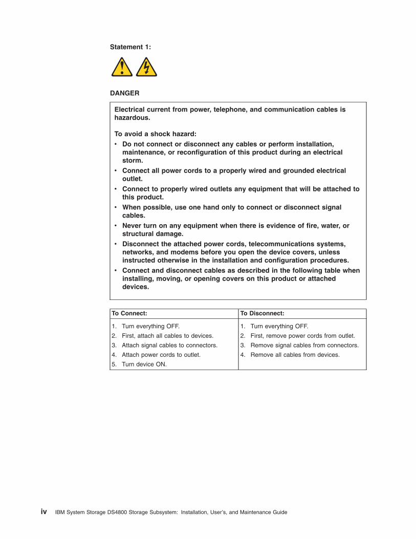
Statement 1:
DANGER
Electrical current from power, telephone, and communication cables is
hazardous.
To avoid a shock hazard:
v Do not connect or disconnect any cables or perform installation,
maintenance, or reconfiguration of this product during an electrical
storm.
v Connect all power cords to a properly wired and grounded electrical
outlet.
v Connect to properly wired outlets any equipment that will be attached to
this product.
v When possible, use one hand only to connect or disconnect signal
cables.
v Never turn on any equipment when there is evidence of fire, water, or
structural damage.
v Disconnect the attached power cords, telecommunications systems,
networks, and modems before you open the device covers, unless
instructed otherwise in the installation and configuration procedures.
v Connect and disconnect cables as described in the following table when
installing, moving, or opening covers on this product or attached
devices.
To Connect: To Disconnect:
1. Turn everything OFF.
2. First, attach all cables to devices.
3. Attach signal cables to connectors.
4. Attach power cords to outlet.
5. Turn device ON.
1. Turn everything OFF.
2. First, remove power cords from outlet.
3. Remove signal cables from connectors.
4. Remove all cables from devices.
iv IBM System Storage DS4800 Storage Subsystem: Installation, User’s, and Maintenance Guide

Statement 2:
CAUTION:
When replacing the lithium battery, use only an equivalent type battery
recommended by the manufacturer. If your system has a module containing a
lithium battery, replace it only with the same module type made by the same
manufacturer. The battery contains lithium and can explode if not properly
used, handled, or disposed of.
Do not:
v Throw or immerse into water
v Heat to more than 100° C (212° F)
v Repair or disassemble
Dispose of the battery as required by local ordinances or regulations.
Safety v

Statement 3:
CAUTION:
When laser products (such as CD-ROMs, DVD drives, fiber optic devices, or
transmitters) are installed, note the following:
v Do not remove the covers. Removing the covers of the laser product could
result in exposure to hazardous laser radiation. There are no serviceable
parts inside the device.
v Use of controls or adjustments or performance of procedures other than
those specified herein might result in hazardous radiation exposure.
DANGER
Some laser products contain an embedded Class 3A or Class 3B laser
diode. Note the following.
Laser radiation when open. Do not stare into the beam, do not view directly
with optical instruments, and avoid direct exposure to the beam.
Class 1 Laser statement
IEC 825-11993 CENELEC EN 60 825
vi IBM System Storage DS4800 Storage Subsystem: Installation, User’s, and Maintenance Guide

Statement 4:
≥ 18 kg (39.7 lb) ≥ 32 kg (70.5 lb) ≥ 55 kg (121.2 lb)
CAUTION:
Use safe practices when lifting.
Statement 5:
CAUTION:
The power control button on the device and the power switch on the power
supply do not turn off the electrical current supplied to the device. The device
also might have more than one power cord. To remove all electrical current
from the device, ensure that all power cords are disconnected from the power
source.
1
2
Safety vii

Statement 6:
CAUTION:
Never remove the cover on a power supply or any part that has the following
label attached.
Hazardous voltage, current, and energy levels are present inside any
component that has this label attached. There are no serviceable parts inside
these components. If you suspect a problem with one of these parts, contact
a service technician.
Statement 7:
DANGER
Handling the cord on this product, or cords associated with accessories
sold with this product, will expose you to lead, a chemical known to the
State of California to cause cancer and birth defects or other reproductive
harm. Wash hands after handling.
viii IBM System Storage DS4800 Storage Subsystem: Installation, User’s, and Maintenance Guide

Contents
Safety . . . . . . . . . . . . . . . . . . . . . . . . . . . . iii
Figures . . . . . . . . . . . . . . . . . . . . . . . . . . . xiii
Tables . . . . . . . . . . . . . . . . . . . . . . . . . . . . xv
About this document . . . . . . . . . . . . . . . . . . . . . xvii
FAStT product renaming . . . . . . . . . . . . . . . . . . . . . xvii
Who should read this document . . . . . . . . . . . . . . . . . . xvii
How this document is organized . . . . . . . . . . . . . . . . . . xviii
DS4000 Storage Subsystem installation tasks - General overview . . . . . . xviii
Getting information, help, and service . . . . . . . . . . . . . . . . xxii
Before you call . . . . . . . . . . . . . . . . . . . . . . . . xxii
Using the documentation . . . . . . . . . . . . . . . . . . . . xxiii
Web sites . . . . . . . . . . . . . . . . . . . . . . . . . xxiii
Software service and support . . . . . . . . . . . . . . . . . . xxv
Hardware service and support . . . . . . . . . . . . . . . . . . xxv
Fire suppression systems . . . . . . . . . . . . . . . . . . . xxv
How to send your comments . . . . . . . . . . . . . . . . . . xxv
Notices and statements used in this document . . . . . . . . . . . . . xxvi
Chapter 1. Introduction . . . . . . . . . . . . . . . . . . . . . . 1
Overview . . . . . . . . . . . . . . . . . . . . . . . . . . . 1
Fibre channel defined . . . . . . . . . . . . . . . . . . . . . . 2
SATA defined . . . . . . . . . . . . . . . . . . . . . . . . . 2
Features at a glance . . . . . . . . . . . . . . . . . . . . . . 2
Clustering support . . . . . . . . . . . . . . . . . . . . . . . 3
Inventory checklist . . . . . . . . . . . . . . . . . . . . . . . . 3
Product updates . . . . . . . . . . . . . . . . . . . . . . . . . 5
Best practices guidelines . . . . . . . . . . . . . . . . . . . . . . 6
Storage server components . . . . . . . . . . . . . . . . . . . . . 7
Intermixing storage expansion enclosures in the same drive loop . . . . . 10
Controllers . . . . . . . . . . . . . . . . . . . . . . . . . 10
Controller cable connections . . . . . . . . . . . . . . . . . . 11
Setting up IP addresses for DS4000 storage controllers . . . . . . . . 14
Controller memory . . . . . . . . . . . . . . . . . . . . . 16
Power supply-fans . . . . . . . . . . . . . . . . . . . . . . 17
Interconnect-battery unit . . . . . . . . . . . . . . . . . . . . 18
SFP modules . . . . . . . . . . . . . . . . . . . . . . . . 20
Specifications . . . . . . . . . . . . . . . . . . . . . . . . . 21
Area requirements . . . . . . . . . . . . . . . . . . . . . . 21
Dimensions . . . . . . . . . . . . . . . . . . . . . . . . 21
Weight . . . . . . . . . . . . . . . . . . . . . . . . . . 21
Shipping dimensions . . . . . . . . . . . . . . . . . . . . . 22
Environmental requirements and specifications . . . . . . . . . . . . 22
Temperature and humidity . . . . . . . . . . . . . . . . . . . 22
Altitude . . . . . . . . . . . . . . . . . . . . . . . . . . 23
Airflow and heat dissipation . . . . . . . . . . . . . . . . . . 23
Shock and vibration requirements . . . . . . . . . . . . . . . . 24
Acoustic noise . . . . . . . . . . . . . . . . . . . . . . . 25
Electrical requirements . . . . . . . . . . . . . . . . . . . . . 25
Site wiring and power . . . . . . . . . . . . . . . . . . . . 26
AC power recovery . . . . . . . . . . . . . . . . . . . . . 26
© Copyright IBM Corp. 2006, 2007 ix
||
||
||

Power cords and receptacles . . . . . . . . . . . . . . . . . . 26
Chapter 2. Installing the storage subsystem . . . . . . . . . . . . . 27
Installation overview . . . . . . . . . . . . . . . . . . . . . . . 27
Handling static-sensitive devices . . . . . . . . . . . . . . . . . . 29
Heat output, airflow, and cooling . . . . . . . . . . . . . . . . . . 29
Preparing for installation . . . . . . . . . . . . . . . . . . . . . 30
Preparing the site . . . . . . . . . . . . . . . . . . . . . . . 32
Preparing the rack cabinet . . . . . . . . . . . . . . . . . . . . 32
Installing the support rails . . . . . . . . . . . . . . . . . . . . . 33
Installing the DS4800 . . . . . . . . . . . . . . . . . . . . . . 37
Releasing and locking a component lever . . . . . . . . . . . . . . 38
Removing the components . . . . . . . . . . . . . . . . . . . 40
Installing the DS4800 on the support rails . . . . . . . . . . . . . . 42
Replacing the components . . . . . . . . . . . . . . . . . . . 44
Chapter 3. Cabling the storage subsystem . . . . . . . . . . . . . . 47
Working with SFPs and fiber-optic cables . . . . . . . . . . . . . . . 47
Handling fiber-optic cables . . . . . . . . . . . . . . . . . . . 48
Installing SFP modules . . . . . . . . . . . . . . . . . . . . . 48
Removing SFP modules . . . . . . . . . . . . . . . . . . . . 50
Installing fiber-optic cables . . . . . . . . . . . . . . . . . . . 51
Using LC-LC fibre-channel cables . . . . . . . . . . . . . . . . . 52
Connecting an LC-LC cable to an SFP module . . . . . . . . . . . 53
Removing an LC-LC fibre-channel cable . . . . . . . . . . . . . 55
Using LC-SC fibre-channel cable adapters . . . . . . . . . . . . . . 55
Connecting an LC-SC cable adapter to a device . . . . . . . . . . 56
Removing an LC-LC cable from an LC-SC cable adapter . . . . . . . 58
Connecting storage expansion enclosures to the DS4800 . . . . . . . . . 59
Redundant drive channel pair . . . . . . . . . . . . . . . . . . 59
Overview of steps to connect storage expansion enclosure to a storage
subsystem . . . . . . . . . . . . . . . . . . . . . . . . . 62
DS4800 drive cabling rules and recommendations . . . . . . . . . . . 67
DS4800 Storage Subsystem drive cabling topologies . . . . . . . . . . 69
One DS4800 and one storage expansion enclosure . . . . . . . . . 70
One DS4800 and two storage expansion enclosures . . . . . . . . . 71
One DS4800 and four storage expansion enclosures . . . . . . . . . 73
One DS4800 and eight storage expansion enclosures . . . . . . . . 75
One DS4800 and fourteen EXP810 storage expansion enclosures . . . . 76
One DS4800 and sixteen EXP710 storage expansion enclosures . . . . 78
One DS4800 to seven EXP810 and eight EXP710 storage expansion
enclosures . . . . . . . . . . . . . . . . . . . . . . . . 80
One DS4800 to two or more storage expansion enclosures in a mixed
environment . . . . . . . . . . . . . . . . . . . . . . . 81
Cabling the storage expansion enclosures to a DS4800 storage subsystem 84
Storage expansion enclosure settings . . . . . . . . . . . . . . . 85
Fibre channel loop and ID settings . . . . . . . . . . . . . . . . 86
DS4000 storage expansion enclosure ID settings . . . . . . . . . . 86
Connecting hosts to the DS4800 . . . . . . . . . . . . . . . . . . 87
Connecting secondary interface cables . . . . . . . . . . . . . . . . 89
Configuring the storage subsystem . . . . . . . . . . . . . . . . . 90
Storage subsystem management methods . . . . . . . . . . . . . . 90
Host-agent (in-band) management method . . . . . . . . . . . . . 91
Direct (out-of-band) management method . . . . . . . . . . . . . 91
Fibre channel connections . . . . . . . . . . . . . . . . . . . . 92
Fibre channel host loop configurations . . . . . . . . . . . . . . . 93
x IBM System Storage DS4800 Storage Subsystem: Installation, User’s, and Maintenance Guide
|||

Redundant host and drive loops . . . . . . . . . . . . . . . . 93
Installing the storage subsystem configuration . . . . . . . . . . . . . 96
Connecting the power cables . . . . . . . . . . . . . . . . . . . . 96
Chapter 4. Operating the storage subsystem . . . . . . . . . . . . 101
Performing the DS4000 Health Check process . . . . . . . . . . . . . 102
Web pages . . . . . . . . . . . . . . . . . . . . . . . . . 103
Hardware responsibilities . . . . . . . . . . . . . . . . . . . . 103
Removing and replacing the front bezel . . . . . . . . . . . . . . . 104
Turning the storage subsystem on and off . . . . . . . . . . . . . . 104
Turning on the storage subsystem . . . . . . . . . . . . . . . . 105
Turning off the storage subsystem . . . . . . . . . . . . . . . . 108
Restoring power after an unexpected shutdown . . . . . . . . . . . . 110
Performing an emergency shutdown . . . . . . . . . . . . . . . . 111
Restoring power after an emergency shutdown . . . . . . . . . . . . 111
Responding to the audible alarm . . . . . . . . . . . . . . . . . . 113
Installing the DS4000 Storage Manager client . . . . . . . . . . . . . 114
Firmware requirements . . . . . . . . . . . . . . . . . . . . 114
Monitoring status through software . . . . . . . . . . . . . . . . . 115
Firmware updates . . . . . . . . . . . . . . . . . . . . . . 116
Troubleshooting the storage subsystem . . . . . . . . . . . . . . 117
Checking the LEDs . . . . . . . . . . . . . . . . . . . . . . . 118
Front bezel LEDs . . . . . . . . . . . . . . . . . . . . . . 118
RAID controller LEDs . . . . . . . . . . . . . . . . . . . . . 120
Numeric display LEDs . . . . . . . . . . . . . . . . . . . . . 123
Power supply-fan LEDs . . . . . . . . . . . . . . . . . . . . 125
Interconnect-battery unit LEDs . . . . . . . . . . . . . . . . . . 127
Recovering from an overheated power supply and fan unit . . . . . . . . 129
Resetting the controller circuit breakers . . . . . . . . . . . . . . . 131
Cache memory and cache battery . . . . . . . . . . . . . . . . . 137
Cache memory . . . . . . . . . . . . . . . . . . . . . . . 137
Subsystem cache battery . . . . . . . . . . . . . . . . . . . 138
Chapter 5. Replacing components . . . . . . . . . . . . . . . . 141
Handling static-sensitive devices . . . . . . . . . . . . . . . . . . 141
Service Action Allowed status LED . . . . . . . . . . . . . . . . . 142
Single component failures . . . . . . . . . . . . . . . . . . . 142
Multiple component failures . . . . . . . . . . . . . . . . . . . 143
Releasing a component lever . . . . . . . . . . . . . . . . . . . 144
Replacing a controller . . . . . . . . . . . . . . . . . . . . . . 145
Upgrading controllers . . . . . . . . . . . . . . . . . . . . . . 150
Replacing a power supply and fan unit . . . . . . . . . . . . . . . . 152
Replacing the interconnect-battery unit . . . . . . . . . . . . . . . . 156
Replacing a backup battery pack . . . . . . . . . . . . . . . . . . 160
Replacing an SFP module . . . . . . . . . . . . . . . . . . . . 163
Installing SFPs and fiber-optic cables . . . . . . . . . . . . . . . . 166
Chapter 6. Hardware maintenance . . . . . . . . . . . . . . . . 167
General checkout . . . . . . . . . . . . . . . . . . . . . . . 167
Using the diagnostic hardware . . . . . . . . . . . . . . . . . . 167
Solving problems . . . . . . . . . . . . . . . . . . . . . . 167
Parts list . . . . . . . . . . . . . . . . . . . . . . . . . . . 174
Appendix A. Additional DS4000 documentation . . . . . . . . . . . 177
DS4000 Storage Manager Version 9 library . . . . . . . . . . . . . . 177
DS4800 Storage Subsystem library . . . . . . . . . . . . . . . . . 178
Contents xi

DS4700 Storage Subsystem library . . . . . . . . . . . . . . . . . 179
DS4500 Storage Subsystem library . . . . . . . . . . . . . . . . . 180
DS4400 Storage Subsystem library . . . . . . . . . . . . . . . . . 181
DS4300 Storage Subsystem library . . . . . . . . . . . . . . . . . 182
DS4200 Express Storage Subsystem library . . . . . . . . . . . . . 183
DS4100 Storage Subsystem library . . . . . . . . . . . . . . . . . 184
DS4000 Storage Expansion Enclosure documents . . . . . . . . . . . 185
Other DS4000 and DS4000-related documents . . . . . . . . . . . . 186
Appendix B. Records . . . . . . . . . . . . . . . . . . . . . 187
Identification numbers . . . . . . . . . . . . . . . . . . . . . . 187
Appendix C. Rack mounting templates . . . . . . . . . . . . . . . 189
Appendix D. Power cords . . . . . . . . . . . . . . . . . . . . 193
Appendix E. Accessibility . . . . . . . . . . . . . . . . . . . . 195
Notices . . . . . . . . . . . . . . . . . . . . . . . . . . . 197
Trademarks . . . . . . . . . . . . . . . . . . . . . . . . . . 197
Important notes . . . . . . . . . . . . . . . . . . . . . . . . 198
Product recycling and disposal . . . . . . . . . . . . . . . . . . 199
Battery return program . . . . . . . . . . . . . . . . . . . . . 199
Electronic emission notices . . . . . . . . . . . . . . . . . . . . 200
Federal Communications Commission (FCC) statement . . . . . . . . 200
Chinese class A compliance statement . . . . . . . . . . . . . . . 200
Industry Canada Class A emission compliance statement . . . . . . . . 201
Australia and New Zealand Class A statement . . . . . . . . . . . . 201
European Union EMC Directive conformance statement . . . . . . . . 201
Taiwanese Class A warning statement . . . . . . . . . . . . . . . 201
Japanese Voluntary Control Council for Interference (VCCI) statement 202
Glossary . . . . . . . . . . . . . . . . . . . . . . . . . . 203
Index . . . . . . . . . . . . . . . . . . . . . . . . . . . . 213
xii IBM System Storage DS4800 Storage Subsystem: Installation, User’s, and Maintenance Guide

Figures
1. DS4800 Storage Subsystem . . . . . . . . . . . . . . . . . . . . . . . . . . . 8
2. Location of components in the storage subsystem . . . . . . . . . . . . . . . . . . . 9
3. Controllers in the storage subsystem . . . . . . . . . . . . . . . . . . . . . . . 11
4. Controller connections . . . . . . . . . . . . . . . . . . . . . . . . . . . . . 12
5. DS4800 configuration with 2 Gbps and 4 Gbps enclosures in different drive channel pairs . . . . 13
6. Power supply-fan . . . . . . . . . . . . . . . . . . . . . . . . . . . . . . . 18
7. Interconnect-battery unit . . . . . . . . . . . . . . . . . . . . . . . . . . . . 19
8. SFP module with fiber-optic cable . . . . . . . . . . . . . . . . . . . . . . . . 20
9. DS4800 Storage Subsystem dimensions . . . . . . . . . . . . . . . . . . . . . . 21
10. DS4800 Storage Subsystem airflow . . . . . . . . . . . . . . . . . . . . . . . . 24
11. Example of cold aisle/hot aisle rack cabinet configuration . . . . . . . . . . . . . . . . 30
12. DS4800 front rack mounting template . . . . . . . . . . . . . . . . . . . . . . . 34
13. DS4800 rear rack mounting template . . . . . . . . . . . . . . . . . . . . . . . 35
14. DS4800 support rail assembly . . . . . . . . . . . . . . . . . . . . . . . . . . 36
15. DS4800 Storage Subsystem front views and back view . . . . . . . . . . . . . . . . 38
16. Component lever and latch . . . . . . . . . . . . . . . . . . . . . . . . . . . 39
17. Removing the power supply and fan units . . . . . . . . . . . . . . . . . . . . . 41
18. Removing the interconnect-battery unit . . . . . . . . . . . . . . . . . . . . . . . 41
19. Removing the controllers . . . . . . . . . . . . . . . . . . . . . . . . . . . . 42
20. Securing the DS4800 to the rack cabinet . . . . . . . . . . . . . . . . . . . . . . 44
21. Replacing the power supply and fan units . . . . . . . . . . . . . . . . . . . . . . 45
22. Replacing the interconnect-battery unit . . . . . . . . . . . . . . . . . . . . . . . 45
23. Replacing the controllers . . . . . . . . . . . . . . . . . . . . . . . . . . . . 46
24. Removing the front bezel . . . . . . . . . . . . . . . . . . . . . . . . . . . . 46
25. Small Form-Factor Pluggable (SFP) module . . . . . . . . . . . . . . . . . . . . . 49
26. Replacing an SFP module . . . . . . . . . . . . . . . . . . . . . . . . . . . 50
27. Unlocking the SFP module latch - plastic variety . . . . . . . . . . . . . . . . . . . 51
28. Unlocking the SFP module latch - wire variety . . . . . . . . . . . . . . . . . . . . 51
29. Removing caps from fiber-optic cables . . . . . . . . . . . . . . . . . . . . . . . 52
30. Connecting fiber-optic cable to SFP . . . . . . . . . . . . . . . . . . . . . . . . 52
31. LC-LC fibre-channel cable . . . . . . . . . . . . . . . . . . . . . . . . . . . 53
32. Removing fiber-optic cable protective caps . . . . . . . . . . . . . . . . . . . . . 54
33. Inserting an LC-LC fibre-channel cable into an SFP module . . . . . . . . . . . . . . . 54
34. LC-LC fibre-channel cable lever and latches . . . . . . . . . . . . . . . . . . . . . 55
35. Removing the LC-LC fibre-channel cable . . . . . . . . . . . . . . . . . . . . . . 55
36. LC-SC fibre-channel cable adapter . . . . . . . . . . . . . . . . . . . . . . . . 56
37. Removing the LC-SC cable adapter protective caps . . . . . . . . . . . . . . . . . . 57
38. Connecting an LC-LC cable into the LC-SC cable adapter . . . . . . . . . . . . . . . 57
39. LC-LC fibre-channel cable lever and latches . . . . . . . . . . . . . . . . . . . . . 58
40. Removing the LC-LC fibre-channel cable from an LC-SC fibre-channel cable adapter . . . . . 58
41. Example 1 of redundant drive channel pairs . . . . . . . . . . . . . . . . . . . . . 61
42. Example 2 of redundant drive channel pairs . . . . . . . . . . . . . . . . . . . . . 62
43. EXP710 /EXP100 port labels . . . . . . . . . . . . . . . . . . . . . . . . . . 63
44. Connecting EXP710 or EXP100 enclosures to DS4800 . . . . . . . . . . . . . . . . . 64
45. EXP810 port labels . . . . . . . . . . . . . . . . . . . . . . . . . . . . . . 65
46. Connecting EXP810 enclosures to DS4800 . . . . . . . . . . . . . . . . . . . . . 66
47. DS4800 Storage Subsystem ports and controllers . . . . . . . . . . . . . . . . . . . 70
48. One DS4800 and one storage expansion enclosure — Recommended cabling . . . . . . . . 71
49. View 1: One DS4800 and two storage expansion enclosures cabling—recommended . . . . . 72
50. View 2: One DS4800 and two storage expansion enclosures cabling — not recommended 73
51. One DS4800 and four storage expansion enclosures—recommended cabling . . . . . . . . 74
52. One DS4800 and eight storage expansion enclosures—recommended cabling . . . . . . . . 75
53. One DS4800 and fourteen EXP810 storage expansion enclosures—recommended cabling 77
© Copyright IBM Corp. 2006, 2007 xiii
||
||
54. One DS4800 and sixteen EXP710 storage expansion enclosure—recommended cabling . . . . 78
55. One DS4800 to seven EXP810 and eight EXP710 storage expansion enclosures—recommended
cabling . . . . . . . . . . . . . . . . . . . . . . . . . . . . . . . . . . 80
56. Acceptable EXP710, EXP810 and EXP100 intermix configuration in a DS4800 environment 82
57. Unacceptable EXP710, EXP810 and EXP100 intermix configuration in a DS4800 environment 83
58. Cabling variations when intermixing EXP100, EXP710, and EXP810 storage expansion
enclosures behind a DS4800 Storage Subsystem . . . . . . . . . . . . . . . . . . . 84
59. Installing an SFP module and LC-LC cable in a DS4800 . . . . . . . . . . . . . . . . 85
60. Installing an SFP module and connecting an LC-LC cable to the storage expansion enclosures 85
61. Location of host cables on RAID controllers . . . . . . . . . . . . . . . . . . . . . 88
62. Cabling diagram for four redundant host connections . . . . . . . . . . . . . . . . . 89
63. Ethernet and serial port locations . . . . . . . . . . . . . . . . . . . . . . . . . 90
64. Host-agent (in-band) managed storage subsystems . . . . . . . . . . . . . . . . . . 91
65. Direct (out-of-band) managed storage subsystems . . . . . . . . . . . . . . . . . . 92
66. Examples of redundant host direct attached fibre channel configurations . . . . . . . . . . 94
67. Example of a single SAN fabric configuration . . . . . . . . . . . . . . . . . . . . 95
68. Example of two storage subsystems in a dual SAN environment . . . . . . . . . . . . . 95
69. Example of a two-cluster configuration . . . . . . . . . . . . . . . . . . . . . . . 96
70. AC power switch and AC and DC power connectors . . . . . . . . . . . . . . . . . . 98
71. Redundant AC power connections to controllers and storage expansion enclosures . . . . . . 99
72. Installing the front bezel . . . . . . . . . . . . . . . . . . . . . . . . . . . . 104
73. AC power switches on the controllers . . . . . . . . . . . . . . . . . . . . . . . 106
74. Front bezel LEDs . . . . . . . . . . . . . . . . . . . . . . . . . . . . . . 119
75. RAID controller LEDs . . . . . . . . . . . . . . . . . . . . . . . . . . . . . 120
76. Numeric display LEDs . . . . . . . . . . . . . . . . . . . . . . . . . . . . 124
77. Power supply-fan LEDs . . . . . . . . . . . . . . . . . . . . . . . . . . . . 126
78. Interconnect-battery unit LEDs . . . . . . . . . . . . . . . . . . . . . . . . . 127
79. Power supply-fan Needs Attention LEDs . . . . . . . . . . . . . . . . . . . . . . 133
80. RAID controller connections . . . . . . . . . . . . . . . . . . . . . . . . . . 134
81. Removing the controller from the storage subsystem . . . . . . . . . . . . . . . . . 135
82. Circuit breaker access holes . . . . . . . . . . . . . . . . . . . . . . . . . . 135
83. Cache Active LEDs . . . . . . . . . . . . . . . . . . . . . . . . . . . . . 138
84. Battery LEDs . . . . . . . . . . . . . . . . . . . . . . . . . . . . . . . . 139
85. Component lever and latch . . . . . . . . . . . . . . . . . . . . . . . . . . 144
86. RAID controller Needs Attention and Service Action Allowed LEDs . . . . . . . . . . . . 146
87. Connectors on the back of each controller . . . . . . . . . . . . . . . . . . . . . 147
88. Unlocking the SFP module latch - plastic variety . . . . . . . . . . . . . . . . . . . 147
89. Unlocking the SFP module latch - wire variety . . . . . . . . . . . . . . . . . . . 148
90. Removing a controller from the DS4800 . . . . . . . . . . . . . . . . . . . . . . 148
91. Overall DS4800 Configuration Needs Attention LED on the DS4800 front bezel . . . . . . . 153
92. Power supply-fan LEDs . . . . . . . . . . . . . . . . . . . . . . . . . . . . 154
93. Removing a power supply and fan unit from the DS4800 . . . . . . . . . . . . . . . 155
94. Overall DS4800 Configuration Needs Attention LED on the DS4800 front bezel . . . . . . . 157
95. Interconnect-battery unit Needs Attention and Service Action Allowed LEDs . . . . . . . . . 158
96. Removing an interconnect-battery unit from the DS4800 . . . . . . . . . . . . . . . . 159
97. Overall DS4800 Configuration Needs Attention LED on the DS4800 front bezel . . . . . . . 161
98. Battery access cover on the interconnect-battery unit . . . . . . . . . . . . . . . . . 161
99. Overall DS4800 Configuration Needs Attention LED on the DS4800 front bezel . . . . . . . 164
100. Needs Attention and SFP Model Bypass LEDs . . . . . . . . . . . . . . . . . . . 164
101. Replacing an SFP module . . . . . . . . . . . . . . . . . . . . . . . . . . . 165
102. DS4800 parts list . . . . . . . . . . . . . . . . . . . . . . . . . . . . . . 175
103. Location of MAC address labels . . . . . . . . . . . . . . . . . . . . . . . . . 187
104. DS4800 front rack mounting template . . . . . . . . . . . . . . . . . . . . . . . 190
105. DS4800 rear rack mounting template . . . . . . . . . . . . . . . . . . . . . . . 191
xiv IBM System Storage DS4800 Storage Subsystem: Installation, User’s, and Maintenance Guide
|||||||

Tables
1. Mapping of FAStT names to DS4000 series names . . . . . . . . . . . . . . . . . . xvii
2. Where to find DS4000 installation and configuration procedures . . . . . . . . . . . . . xix
3. Features at a glance . . . . . . . . . . . . . . . . . . . . . . . . . . . . . . 3
4. Maximum number of storage expansion enclosures . . . . . . . . . . . . . . . . . . 9
5. Possible combinations of 14-drive and 16-drive storage expansion enclosures per redundant
drive/channel loop pair in a DS4800 configuration . . . . . . . . . . . . . . . . . . . 10
6. RAID controller specifications . . . . . . . . . . . . . . . . . . . . . . . . . . 16
7. DS4800 Storage Subsystem weights . . . . . . . . . . . . . . . . . . . . . . . 21
8. DS4800 Storage Subsystem component weights . . . . . . . . . . . . . . . . . . . 22
9. DS4800 Storage Subsystem shipping carton dimensions . . . . . . . . . . . . . . . . 22
10. Temperature and humidity requirements . . . . . . . . . . . . . . . . . . . . . . 22
11. DS4800 Storage Subsystem altitude ranges . . . . . . . . . . . . . . . . . . . . . 23
12. DS4800 Storage Subsystem power and heat dissipation . . . . . . . . . . . . . . . . 24
13. DS4800 Storage Subsystem operational vibration specifications . . . . . . . . . . . . . 25
14. DS4800 Storage Subsystem sound levels . . . . . . . . . . . . . . . . . . . . . 25
15. IBM System Storage DS4800 AC power requirements . . . . . . . . . . . . . . . . . 25
16. Different ways to connect four storage expansion enclosures to the DS4800 . . . . . . . . . 68
17. DS4800 Storage Subsystem drive ports and drive channels . . . . . . . . . . . . . . . 70
18. Description of Figure 48 . . . . . . . . . . . . . . . . . . . . . . . . . . . . 71
19. Description of Figure 49 . . . . . . . . . . . . . . . . . . . . . . . . . . . . 72
20. Description of Figure 51 . . . . . . . . . . . . . . . . . . . . . . . . . . . . 74
21. Description of Figure 52 . . . . . . . . . . . . . . . . . . . . . . . . . . . . 75
22. Description of Figure 53 . . . . . . . . . . . . . . . . . . . . . . . . . . . . 77
23. Description of Figure 54 . . . . . . . . . . . . . . . . . . . . . . . . . . . . 78
24. Description of Figure 55 . . . . . . . . . . . . . . . . . . . . . . . . . . . . 80
25. Description of Figure 56 on page 82 . . . . . . . . . . . . . . . . . . . . . . . . 82
26. Description of Figure 57 on page 83 . . . . . . . . . . . . . . . . . . . . . . . . 83
27. Description of Figure 58 on page 84 . . . . . . . . . . . . . . . . . . . . . . . . 84
28. Recommended enclosure ID settings scheme . . . . . . . . . . . . . . . . . . . . 87
29. Description of Figure 61 . . . . . . . . . . . . . . . . . . . . . . . . . . . . 91
30. Description of Figure 62 . . . . . . . . . . . . . . . . . . . . . . . . . . . . 92
31. Description of Figure 67 . . . . . . . . . . . . . . . . . . . . . . . . . . . . 98
32. Firmware requirements . . . . . . . . . . . . . . . . . . . . . . . . . . . . 114
33. Description of Figure 71 . . . . . . . . . . . . . . . . . . . . . . . . . . . . 119
34. RAID controller LEDs . . . . . . . . . . . . . . . . . . . . . . . . . . . . . 120
35. Host and drive channel LED definitions . . . . . . . . . . . . . . . . . . . . . . 123
36. Numeric display diagnostic codes . . . . . . . . . . . . . . . . . . . . . . . . 125
37. Power supply-fan LEDs . . . . . . . . . . . . . . . . . . . . . . . . . . . . 126
38. Interconnect-battery unit LEDs . . . . . . . . . . . . . . . . . . . . . . . . . 127
39. DS4800 Symptom-to-FRU index . . . . . . . . . . . . . . . . . . . . . . . . . 168
40. Parts list (System Storage DS4800 Storage Subsystem) . . . . . . . . . . . . . . . . 175
41. DS4000 Storage Manager Version 9 titles by user tasks . . . . . . . . . . . . . . . . 177
42. DS4800 Storage Subsystem document titles by user tasks . . . . . . . . . . . . . . . 178
43. DS4700 Storage Subsystem document titles by user tasks . . . . . . . . . . . . . . . 179
44. DS4500 Storage Subsystem document titles by user tasks . . . . . . . . . . . . . . . 180
45. DS4400 Storage Subsystem document titles by user tasks . . . . . . . . . . . . . . . 181
46. DS4300 Storage Subsystem document titles by user tasks . . . . . . . . . . . . . . . 182
47. DS4200 Express Storage Subsystem document titles by user tasks . . . . . . . . . . . 183
48. DS4100 Storage Subsystem document titles by user tasks . . . . . . . . . . . . . . . 184
49. DS4000 Storage Expansion Enclosure document titles by user tasks . . . . . . . . . . . 185
50. DS4000 and DS4000–related document titles by user tasks . . . . . . . . . . . . . . 186
51. DS4000 Storage Manager alternate keyboard operations . . . . . . . . . . . . . . . 195
© Copyright IBM Corp. 2006, 2007 xv
|||
||
||||||||

xvi IBM System Storage DS4800 Storage Subsystem: Installation, User’s, and Maintenance Guide
About this document
This document provides instructions for installing and customizing the configuration
of your IBM System Storage DS4800 Storage Subsystem. It also provides hardware
maintenance procedures and troubleshooting information.
FAStT product renaming
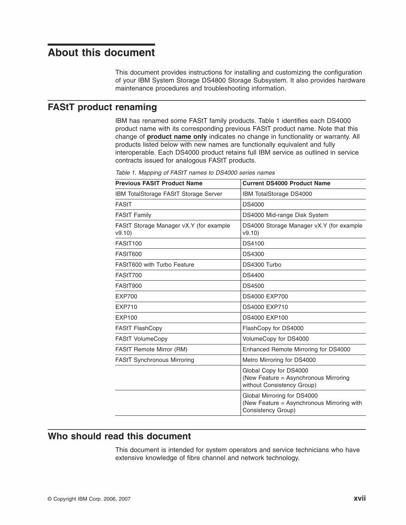
IBM has renamed some FAStT family products. Table 1 identifies each DS4000
product name with its corresponding previous FAStT product name. Note that this
change of product name only indicates no change in functionality or warranty. All
products listed below with new names are functionally equivalent and fully
interoperable. Each DS4000 product retains full IBM service as outlined in service
contracts issued for analogous FAStT products.
Table 1. Mapping of FAStT names to DS4000 series names
Previous FAStT Product Name Current DS4000 Product Name
IBM TotalStorage FAStT Storage Server IBM TotalStorage DS4000
FAStT DS4000
FAStT Family DS4000 Mid-range Disk System
FAStT Storage Manager vX.Y (for example
v9.10)
DS4000 Storage Manager vX.Y (for example
v9.10)
FAStT100 DS4100
FAStT600 DS4300
FAStT600 with Turbo Feature DS4300 Turbo
FAStT700 DS4400
FAStT900 DS4500
EXP700 DS4000 EXP700
EXP710 DS4000 EXP710
EXP100 DS4000 EXP100
FAStT FlashCopy FlashCopy for DS4000
FAStT VolumeCopy VolumeCopy for DS4000
FAStT Remote Mirror (RM) Enhanced Remote Mirroring for DS4000
FAStT Synchronous Mirroring Metro Mirroring for DS4000
Global Copy for DS4000(New Feature = Asynchronous Mirroring
without Consistency Group)
Global Mirroring for DS4000(New Feature = Asynchronous Mirroring with
Consistency Group)
Who should read this document
This document is intended for system operators and service technicians who have
extensive knowledge of fibre channel and network technology.
© Copyright IBM Corp. 2006, 2007 xvii

How this document is organized
Chapter 1, “Introduction,” on page 1 describes the IBM System Storage DS4800
Storage Subsystem. This chapter includes an inventory checklist and an overview
of the storage subsystem features, operating specifications, and components.
Chapter 2, “Installing the storage subsystem,” on page 27 contains instructions for
installing the DS4800 Storage Subsystem in a standard rack cabinet and setting the
interface options.
Chapter 3, “Cabling the storage subsystem,” on page 47 contains fibre channel and
power cabling information for the DS4800 Storage Subsystem.
Chapter 4, “Operating the storage subsystem,” on page 101 contains instructions for
powering the DS4800 Storage Subsystem on or off during either normal or
emergency situations. It also contains information on how to check the LEDs on the
front and back of the storage subsystem.
Chapter 5, “Replacing components,” on page 141 contains step-by-step instructions
for how to install or remove customer replaceable units (CRUs), such as power
supply and fan units, RAID controllers, and interconnect-battery units.
Chapter 6, “Hardware maintenance,” on page 167 contains problems, symptoms,
and error messages that are specific to the DS4800 Storage Subsystem. It also
contains the parts listing for the DS4800 Storage Subsystem.
Appendix A, “Additional DS4000 documentation,” on page 177 provides references
to other DS4000 publications.
Appendix B, “Records,” on page 187 provides a table that you can use to record
and update important information about your DS4800, including serial number,
model and machine type, and MAC addresses.
Appendix C, “Rack mounting templates,” on page 189 provides the rack mounting
templates for installation of the DS4800. If you want to tear out the templates from
the document for use during installation, use these copies of the templates.
Appendix D, “Power cords,” on page 193 lists power cord information for the
DS4800.
Appendix E, “Accessibility,” on page 195 provides information about DS4000
Storage Manager accessibility features.
DS4000 Storage Subsystem installation tasks - General overview
Table 2 on page xix provides a sequential list of many installation and configuration
tasks that are common to most DS4000 configurations. When you install and
configure your DS4000 storage subsystem, refer to this table to find the
documentation that explains how to complete each task.
See also: The DS4000 Storage Server and Storage Expansion Enclosure Quick
Start Guide provides an excellent overview of the installation process.
xviii IBM System Storage DS4800 Storage Subsystem: Installation, User’s, and Maintenance Guide

Table 2. Where to find DS4000 installation and configuration procedures
Installation task Where to find information or procedures
1 Plan the installation v DS4000 Storage Manager Concepts Guide
v DS4000 Storage Manager Installation and Support Guide for
AIX, HP-UX, Solaris and Linux on POWER
v DS4000 Storage Manager Installation and Support Guide for
Windows 2000/Server 2003, NetWare, ESX Server, and
Linux
v DS4100 Storage Subsystem Installation, User’s, and
Maintenance Guide
v DS4200 Express Storage Subsystem Installation, User’s, and
Maintenance Guide
v DS4300 Storage Subsystem Installation, User's, and
Maintenance Guide
v DS4400 Fibre Channel Storage Server Installation and
Support Guide
v DS4500 Storage Subsystem Installation, User's, and
Maintenance Guide
v DS4700 Storage Subsystem Installation, User’s, and
Maintenance Guide
v DS4800 Storage Subsystem Installation, User’s, and
Maintenance Guide
2 Mount the DS4000
storage subsystem in
the rack
v DS4800 Storage Subsystem Installation, User’s, and
Maintenance Guide
v DS4700 Storage Subsystem Installation, User’s, and
Maintenance Guide
v DS4400 and DS4500 Rack Mounting Instructions
v DS4300 Rack Mounting Instructions
v DS4200 Express Storage Subsystem Installation, User’s, and
Maintenance Guide
v DS4100 Storage Subsystem Installation, User’s and
Maintenance Guide
3 Mount the DS4000
EXP storage
expansion unit in the
rack
v DS4000 EXP100 Storage Expansion Unit Installation, User’s
and Maintenance Guide
v DS4000 EXP420 Storage Expansion Enclosures Installation,
User’s, and Maintenance Guide
v DS4000 EXP700 and EXP710 Storage Expansion Enclosures
Installation, User’s, and Maintenance Guide
v DS4000 EXP810 Storage Expansion Enclosures Installation,
User’s, and Maintenance Guide
v FAStT EXP500 Installation and User’s Guide
About this document xix
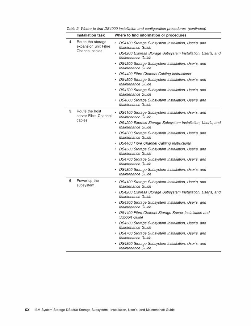
Table 2. Where to find DS4000 installation and configuration procedures (continued)
Installation task Where to find information or procedures
4 Route the storage
expansion unit Fibre
Channel cables
v DS4100 Storage Subsystem Installation, User’s, and
Maintenance Guide
v DS4200 Express Storage Subsystem Installation, User’s, and
Maintenance Guide
v DS4300 Storage Subsystem Installation, User’s, and
Maintenance Guide
v DS4400 Fibre Channel Cabling Instructions
v DS4500 Storage Subsystem Installation, User’s, and
Maintenance Guide
v DS4700 Storage Subsystem Installation, User’s, and
Maintenance Guide
v DS4800 Storage Subsystem Installation, User’s, and
Maintenance Guide
5 Route the host
server Fibre Channel
cables
v DS4100 Storage Subsystem Installation, User’s, and
Maintenance Guide
v DS4200 Express Storage Subsystem Installation, User’s, and
Maintenance Guide
v DS4300 Storage Subsystem Installation, User’s, and
Maintenance Guide
v DS4400 Fibre Channel Cabling Instructions
v DS4500 Storage Subsystem Installation, User’s, and
Maintenance Guide
v DS4700 Storage Subsystem Installation, User’s, and
Maintenance Guide
v DS4800 Storage Subsystem Installation, User’s, and
Maintenance Guide
6 Power up the
subsystem
v DS4100 Storage Subsystem Installation, User’s, and
Maintenance Guide
v DS4200 Express Storage Subsystem Installation, User’s, and
Maintenance Guide
v DS4300 Storage Subsystem Installation, User’s, and
Maintenance Guide
v DS4400 Fibre Channel Storage Server Installation and
Support Guide
v DS4500 Storage Subsystem Installation, User’s, and
Maintenance Guide
v DS4700 Storage Subsystem Installation, User’s, and
Maintenance Guide
v DS4800 Storage Subsystem Installation, User’s, and
Maintenance Guide
xx IBM System Storage DS4800 Storage Subsystem: Installation, User’s, and Maintenance Guide
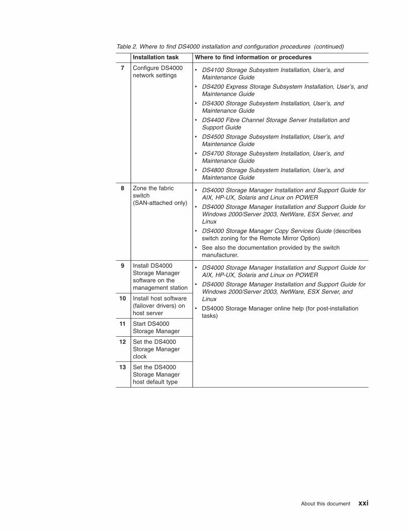
Table 2. Where to find DS4000 installation and configuration procedures (continued)
Installation task Where to find information or procedures
7 Configure DS4000
network settings
v DS4100 Storage Subsystem Installation, User’s, and
Maintenance Guide
v DS4200 Express Storage Subsystem Installation, User’s, and
Maintenance Guide
v DS4300 Storage Subsystem Installation, User’s, and
Maintenance Guide
v DS4400 Fibre Channel Storage Server Installation and
Support Guide
v DS4500 Storage Subsystem Installation, User’s, and
Maintenance Guide
v DS4700 Storage Subsystem Installation, User’s, and
Maintenance Guide
v DS4800 Storage Subsystem Installation, User’s, and
Maintenance Guide
8 Zone the fabric
switch
(SAN-attached only)
v DS4000 Storage Manager Installation and Support Guide for
AIX, HP-UX, Solaris and Linux on POWER
v DS4000 Storage Manager Installation and Support Guide for
Windows 2000/Server 2003, NetWare, ESX Server, and
Linux
v DS4000 Storage Manager Copy Services Guide (describes
switch zoning for the Remote Mirror Option)
v See also the documentation provided by the switch
manufacturer.
9 Install DS4000
Storage Manager
software on the
management station
v DS4000 Storage Manager Installation and Support Guide for
AIX, HP-UX, Solaris and Linux on POWER
v DS4000 Storage Manager Installation and Support Guide for
Windows 2000/Server 2003, NetWare, ESX Server, and
Linux
v DS4000 Storage Manager online help (for post-installation
tasks)
10 Install host software
(failover drivers) on
host server
11 Start DS4000
Storage Manager
12 Set the DS4000
Storage Manager
clock
13 Set the DS4000
Storage Manager
host default type
About this document xxi

Table 2. Where to find DS4000 installation and configuration procedures (continued)
Installation task Where to find information or procedures
14 Verify DS4000
subsystem health
v DS4100 Storage Subsystem Installation, User’s, and
Maintenance Guide
v DS4200 Express Storage Subsystem Installation, User’s, and
Maintenance Guide
v DS4300 Storage Subsystem Installation, User’s, and
Maintenance Guide
v DS4400 Fibre Channel Storage Server Installation and
Support Guide
v DS4500 Storage Subsystem Installation, User’s, and
Maintenance Guide
v DS4700 Storage Subsystem Installation, User’s, and
Maintenance Guide
v DS4800 Storage Subsystem Installation, User’s, and
Maintenance Guide
15 Enable DS4000
Storage Manager
premium feature
keys
Copy Services premium features
DS4000 Storage Manager Copy Services Guide
FC/SATA Intermix premium feature
DS4000 Fibre Channel and Serial ATA Intermix
Premium Feature Installation Overview
Storage Partitioning (and general premium features
information)
v DS4000 Storage Manager Concepts Guide
v DS4000 Storage Manager Installation and Support
Guide for AIX, HP-UX, Solaris and Linux on POWER
v DS4000 Storage Manager Installation and Support
Guide for Windows 2000/Server 2003, NetWare,
ESX Server, and Linux
16 Configure arrays and
logical drives
v DS4000 Storage Manager Installation and Support Guide for
AIX, HP-UX, Solaris and Linux on POWER
v DS4000 Storage Manager Installation and Support Guide for
Windows 2000/Server 2003, NetWare, ESX Server, and
Linux
v DS4000 Storage Manager online help
17 Configure host
partitions
18 Verify host access to
DS4000 storage
Getting information, help, and service
If you need help, service, or technical assistance or just want more information
about IBM products, you will find a wide variety of sources available from IBM to
assist you. This section contains information about where to go for additional
information about IBM and IBM products, what to do if you experience a problem
with your system, and whom to call for service, if it is necessary.
Before you call
Before you call, take these steps to try to solve the problem yourself:
v Check all cables to make sure that they are connected.
v Check the power switches to make sure that the system is turned on.
xxii IBM System Storage DS4800 Storage Subsystem: Installation, User’s, and Maintenance Guide

v Use the troubleshooting information in your system documentation, and use the
diagnostic tools that come with your system.
v Check for technical information, hints, tips, and new device drivers at the IBM
support Web site pages that are listed in this section.
v Use an IBM discussion forum on the IBM Web site to ask questions.
You can solve many problems without outside assistance by following the
troubleshooting procedures that IBM provides in the DS4000 Storage Manager
online help or in the documents that are provided with your system and software.
The information that comes with your system also describes the diagnostic tests
that you can perform. Most subsystems, operating systems, and programs come
with information that contains troubleshooting procedures and explanations of error
messages and error codes. If you suspect a software problem, see the information
for the operating system or program.
Using the documentation
Information about your IBM system and preinstalled software, if any, is available in
the documents that come with your system. This includes printed books, online
documents, readme files, and help files. See the troubleshooting information in your
system documentation for instructions for using the diagnostic programs. The
troubleshooting information or the diagnostic programs might tell you that you need
additional or updated device drivers or other software.
Web sites
The most up-to-date information about DS4000 storage subsystems and DS4000
Storage Manager, including documentation and the most recent software, firmware,
and NVSRAM downloads, can be found at the following Web sites.
DS4000 Midrange Disk Systems
Find the latest information about IBM System Storage disk storage systems,
including all of the DS4000 storage subsystems:
www-1.ibm.com/servers/storage/disk/ds4000/
IBM System Storage products
Find information about all IBM System Storage products:
www.storage.ibm.com/
Support for IBM System Storage disk storage systems
Find links to support pages for all IBM System Storage disk storage
systems, including DS4000 storage subsystems and expansion units:
www-304.ibm.com/jct01004c/systems/support/supportsite.wss/brandmain?brandind=5345868
System Storage DS4000 interoperability matrix
Find the latest information about operating system and HBA support,
clustering support, storage area network (SAN) fabric support, and DS4000
Storage Manager feature support:
www-1.ibm.com/servers/storage/disk/ds4000/interop-matrix.html
DS4000 Storage Manager readme files
1. Go to the following Web site:
www-304.ibm.com/jct01004c/systems/support/supportsite.wss/brandmain?brandind=5345868
About this document xxiii

2. In the Product family drop-down menu, select Disk systems, and in the
Product drop-down menu, select your Storage Subsystem (for example,
DS4800 Midrange Disk System). Then click Go.
3. When the subsystem support page opens, click the Install/use tab, then
click the DS4000 Storage Manager Pubs and Code link. The
Downloads page for the subsystem opens.
4. When the download page opens, ensure that the Storage Mgr tab is
selected. A table displays.
5. In the table, find the entry that lists the Storage Manager package for
your operating system, then click on the corresponding v9.xx link in the
“Current version and readmes” column. The Storage Manager page for
your operating system opens.
6. Click the link for the readme file.
Storage Area Network (SAN) support
Find information about using SAN switches, including links to user guides
and other documents:
www.ibm.com/servers/storage/support/san/index.html
DS4000 technical support
Find downloads, hints and tips, documentation, parts information, HBA and
Fibre Channel support:
www-304.ibm.com/jct01004c/systems/support/supportsite.wss/brandmain?brandind=5345868In the Product family drop-down menu, select
Disk systems, and in the Product drop-down menu, select your Storage
Subsystem (for example, DS4800 Midrange Disk System). Then click Go.
Premium feature activation
Generate a DS4000 premium feature activation key file by using the online
tool:
www-912.ibm.com/PremiumFeatures/jsp/keyInput.jsp
IBM publications center
Find IBM publications:
www.ibm.com/shop/publications/order/
Support for System p servers
Find the latest information supporting System p AIX and Linux servers:
www-304.ibm.com/jct01004c/systems/support/supportsite.wss/brandmain?brandind=5000025
Support for System x servers
Find the latest information supporting System x Intel- and AMD-based
servers:
www-304.ibm.com/jct01004c/systems/support/supportsite.wss/brandmain?brandind=5000008
Fix delivery center for AIX and Linux on POWER
Find the latest AIX and Linux on POWER information and downloads:
www-912.ibm.com/eserver/support/fixes/fcgui.jsp
In the Product family drop-down menu, select UNIX servers. Then select
your product and fix type from the subsequent drop-down menus.
xxiv IBM System Storage DS4800 Storage Subsystem: Installation, User’s, and Maintenance Guide

Eserver System p and AIX information center
Find everything you need to know about using AIX with System p and
POWER servers:
publib.boulder.ibm.com/infocenter/pseries/index.jsp?
Support for Linux on System p
Find information about using Linux on System p servers:
www.ibm.com/servers/eserver/pseries/linux/
Linux on POWER resource center
Find information about using Linux on POWER servers:
www.ibm.com/servers/enable/linux/power/
Software service and support
Through IBM Support Line, for a fee you can get telephone assistance with usage,
configuration, and software problems. For information about which products are
supported by Support Line in your country or region, go to the following Web site:
www.ibm.com/services/sl/products/
For more information about the IBM Support Line and other IBM services, go to the
following Web sites:
v www.ibm.com/services/
v www.ibm.com/planetwide/
Hardware service and support
You can receive hardware service through IBM Integrated Technology Services or
through your IBM reseller, if your reseller is authorized by IBM to provide warranty
service. Go to the following Web site for support telephone numbers:
www.ibm.com/planetwide/
In the U.S. and Canada, hardware service and support is available 24 hours a day,
7 days a week. In the U.K., these services are available Monday through Friday,
from 9 a.m. to 6 p.m.
Fire suppression systems
A fire suppression system is the responsibility of the customer. The customer’s own
insurance underwriter, local fire marshal, or a local building inspector, or both,
should be consulted in selecting a fire suppression system that provides the correct
level of coverage and protection. IBM designs and manufactures equipment to
internal and external standards that require certain environments for reliable
operation. Because IBM does not test any equipment for compatibility with fire
suppression systems, IBM does not make compatibility claims of any kind nor does
IBM provide recommendations on fire suppression systems.
How to send your comments
Your feedback is important to help us provide the highest quality information. If you
have any comments about this document, you can submit them in one of the
following ways:
About this document xxv

Submit your comments by e-mail to:
Be sure to include the name and order number of the document and, if
applicable, the specific location of the text that you are commenting on,
such as a page number or table number.
Fill out the Readers’ Comments form (RCF) at the back of this document
and return it by mail or give it to an IBM representative.
If the RCF has been removed, send your comments to:
International Business Machines Corporation
Information Development
Department GZW
9000 South Rita Road
Tucson, Arizona
USA
85744-0001
Be sure to include the name and order number of the document and, if
applicable, the specific location of the text that you are commenting on,
such as a page number or table number.
Notices and statements used in this document
The caution and danger statements used in this document also appear in the
multilingual Safety Information document provided with your IBM DS4800. Each
caution and danger statement is numbered for easy reference to the corresponding
statements in the safety document.
The following types of notices and statements are used in this document:
v Note: These notices provide important tips, guidance, or advice.
v Important: These notices provide information or advice that might help you avoid
inconvenient or problem situations.
v Attention: These notices indicate possible damage to programs, devices, or
data. An attention notice is placed just before the instruction or situation in which
damage could occur.
v Caution: These statements indicate situations that can be potentially hazardous
to you. A caution statement is placed just before the description of a potentially
hazardous procedure step or situation.
v Danger: These statements indicate situations that can be potentially lethal or
extremely hazardous to you. A danger statement is placed just before the
description of a potentially lethal or extremely hazardous procedure step or
situation.
xxvi IBM System Storage DS4800 Storage Subsystem: Installation, User’s, and Maintenance Guide

Chapter 1. Introduction
This chapter describes the operating specifications, features, and components for
the IBM System Storage® DS4800 (Machine Type 1815) Storage Subsystem
(hereafter referred to as DS4800 or storage subsystem).
This chapter also includes an inventory checklist and important information on best
practices guidelines and product updates for your DS4800.
Overview
IBM DS4000 solutions support the large and growing data storage requirements of
business-critical applications. These scalable IBM DS4000 solutions offer you data
access and protection to meet your existing enterprise storage requirements and
prepare for the future.
The IBM System Storage DS4800 storage system is designed to provide solutions
to meet the needs of midrange/departmental storage requirements, delivering high
performance, advanced function, high availability, modular and scalable storage
capacity, with SAN-attached 4-Gbps fibre channel (FC) connectivity, and support for
RAID levels 0, 1, 3, and 5 up to over 89 terabytes (TB).
Note: The stated maximum capacity was calculated using 224 drives of the
currently available 400G SATA hard drives.
The DS4800 is designed to deliver up to a twofold IOP performance increase over
the current DS4500 offering and represents the sixth-generation architecture of the
DS4000 series family. A 4-U rack-mountable enclosure houses the DS4800
redundant, dual-active intelligent RAID controllers equipped with sixteen 4-Gbps
fibre channel ports (eight ports per controller), for attachment of host servers and
DS4000 storage expansion enclosures.
The DS4800 supports attachment of up to 16 DS4000 EXP100 or EXP710 storage
expansion enclosures, or up to 14 DS4000 EXP810 storage expansion enclosures,
resulting in the capability to connect to up to 224 disk drives and enabling storage
configurations of over 89 TB. DS4800 models 82A/H, 84A/H and 88A/H support the
attachment of up to 224 drives as standard. The DS4800 model 80A/H supports
only the attachment of up to 112 drives as standard. An entitlement must be
purchased to connect up to 224 drives behind a DS4800 model 80A/H.
The DS4800 supports configurations of FC or Serial Advanced Technology
Attachment (SATA) disks, or a mix of both types of disk drives by use of the
optional DS4800 Fibre Channel/SATA Enclosure Intermix feature.
Advanced DS4000 storage management, copy service options, and optional
advanced disaster recovery functions are available for the DS4800, including
FlashCopy®, VolumeCopy, and Enhanced Remote Mirroring.
The DS4000 Storage Manager client is also available for the DS4800. This storage
management software is designed to help centralize storage management, help
simplify partitioning of the DS4000 series storage into as many as 64 virtual
servers, and strategically allocate storage capacity to maximize storage space.
The DS4800 RAID controller cache size varies depending the DS4800 model.
Currently, the cache size is either 2 GB, 4 GB or 8 GB. Depending on the model,
© Copyright IBM Corp. 2006, 2007 1
|||||||
|||

the DS4800 either ships with the 8-storage-partition premium feature or can be
ordered with 8-, 16-, or 64-storage-partition premium features. The operating
system host kit shipped with the DS4800 also depends on the model ordered.
DS4800 models 80H, 82H, 84H, and 88H come with the Windows operating system
and 8 storage partitions. Please contact your IBM sales representatives or reseller
for information on the various DS4800 models and options.
Attention: DS4800 models 82, 84 and 88 will be shipped with controller firmware
version 6.15.xx.xx. The DS4800 model 80 will be shipped with version 6.16.xx.xx
and will not have support for versions 6.15.xx.xx or 6.14.xx.xx as will the other
models.
Fibre channel defined
Fibre channel technology is outlined in the SCSI-3 Fibre Channel Protocol
(SCSI-FCP) standard. Fibre channel is a high-speed data transport technology that
is used for mass storage and networking. Using a fibre-channel arbitrated loop
(FC-AL), more than 100 fibre-channel devices1 can be supported, compared to 15
small computer system interface (SCSI) devices.
The optical fibre channel connection from the DS4800 to fibre channel host bus
adapter ports, or from the DS4800 to DS4000 storage expansion enclosure ports, is
a 4-Gbps fibre channel connection that supports a data transfer rate up to 400
MBps at half-duplex and 800 MBps at full-duplex.
SATA defined
The Serial Advanced Technology Attachment (SATA) interface offers increased data
rate performance over Parallel Advanced Technology Attachment (ATA), while
maintaining the benefits of ATA. SATA is designed to overcome the performance
barriers that have been forecasted for current parallel technologies while
maintaining the cost-efficiency of Parallel ATA. SATA specifications allow for thinner,
more flexible cables, and lower pin counts. It also enables easier, more flexible
cable routing management and the use of smaller connectors than is possible with
the existing Parallel ATA technology.
The Serial ATA Working Group introduced the first SATA specification, Serial ATA
1.0, in 2001 http://www.serialata.org.
Features at a glance
Table 3 on page 3 summarizes the features of the storage subsystem. For a list of
the operating specifications, such as weight, height, and heat output, see
“Specifications” on page 21.
1. For the DS4800, each drive is considered to be a device in a fibre channel loop, even though the DS4800 might connect with
SATA as well as fibre channel drives.
2 IBM System Storage DS4800 Storage Subsystem: Installation, User’s, and Maintenance Guide

Table 3. Features at a glance
General
v Modular components:
– RAID controllers (2), with either 2
GB, 4 GB or 8 GB of cache memory
per controller (depending on model)
– Power supply-cooling fan units (2)
– Interconnect-battery unit (1)v Technology:
– Support for RAID 0, 1, 3 and 5 disk
arrays
– Support for clustering
– Fibre channel host interface
– Redundant controllers and power
supply/cooling system
– Hot-swap technology for controllers,
power supply and fan units, cache
battery, and interconnect-battery unit
Attention: Never remove the
interconnect-battery unit unless
directed to do so by an IBM Service
representative.
v User interface:
– Built-in power, activity, and fault
(Needs Attention) light emitting
diodes (LEDs)
– Identification labeling on customer
replaceable units (CRUs), rear LEDs,
switches, and connectors
– Easy-to-replace power supply and
fan units, RAID controllers, cache
battery, and interconnect-battery unit
RAID controllers
v Fibre channel interface: sixteen small
form-factor pluggable (SFP) ports for
incoming and outgoing fibre-channel
cables (There are eight SFP ports on
each RAID controller: four ports are
reserved for host connections and four
ports are reserved for drive expansion
enclosures connections.)
v Host connections: Four
1-Gbps/2-Gbps/4-Gbps
(auto-negotiated) fibre channel host-side
connections per controller
Attached storage expansion enclosures
v Four dual-ported drive channel
connections (2 per RAID controller)
enabled to support 2-Gbps/4 Gbps fibre
channel connections
v Supports attachment of DS4000 2 Gbps
EXP100 and EXP710, and 2 Gbps/4
Gbps EXP810 storage expansion
enclosures
Note: DS4000 EXP700s are not
supported by the DS4800 unless they
have been upgraded (with the DS4000
EXP700 Models 1RU/1RX
Switched-ESM Option Upgrade Kit) to
have the same internal switched
capabilities as the DS4000 EXP710.
Attention: The DS4800 does not
support the attachment of storage
expansion enclosures operating at 1
Gbps, such as the EXP500.
Clustering support
Clustering is a means of sharing array groups among controllers to provide
redundancy of controllers and servers. This redundancy is important if a hardware
component fails. If a hardware component failure occurs in a cluster, another server
takes ownership of the array group.
Clustering requires software specific to your operating system. For more information
about clustering, go to the following Web sites:
v www.pc.ibm.com/us/compat/nos/matrix.shtml
v www-03.ibm.com/servers/storage/disk/ds4000/ds4800/interop.html
Inventory checklist
After you unpack the DS4800, verify that you have the following items. See
“Storage server components” on page 7 for the locations of hardware components
on the DS4800.
Note: Depending on your DS4800 order, your shipping box might contain additional
materials not listed in the following checklist. Review the inventory checklist
included in the DS4800 shipping box for any additional parts, and use that
checklist in combination with the following information.
v Hardware
– One DS4800 bezel (front cover)
– Two RAID controllers (shipped installed in the DS4800)
– Two power supply and fan units (shipped installed in the DS4800)
– One interconnect-battery unit with two cache-backup battery packs (shipped
installed in the DS4800)
– Two line cord jumpers
Chapter 1. Introduction 3

Line cord jumpers are power cables used to connect the DS4800 RAID
controller units to the IBM-certified rack power distribution units (PDUs)
installed in the rack cabinet.
– Eight 4 Gbps SFP modules (These SFP modules are already installed in the
DS4800 drive (4) and host (4) ports.)
– One rack-mounting hardware kit, including:
- Two rails (right and left assemblies)
- Eight M5 black hex-head screws
– Wrap plug and coupler kit
Use the wrap plug and coupler kit for FC link diagnostics. See the IBM
System Storage DS4000 Problem Determination Guide for more information.
Attention: The DS4800 does not ship with region-specific power cords. You
must obtain the IBM-approved power cords for your region. See Appendix D,
“Power cords,” on page 193 for the IBM-approved power cords for your region.
v Software and documentation
– Host software attachment kit
Depending on the DS4800 model you order, your DS4800 will ship with either
the Microsoft® Windows® host software attachment kit or with your choice of
host software kits (Windows, AIX®, Linux®, Netware, SUN Solaris, HP-UX,
Linux on POWER™, or VMware). The host software kit grants you permission
to attach host servers using the appropriate operating system to the DS4800.
The kit includes a DS4000 Storage Manager Version 9 Support CD that has
the appropriate IBM DS4000 Storage Manager host software. The CD also
contains includes firmware, online help, and publications in Adobe Acrobat
Portable Document Format (PDF). (For a list of available IBM DS4000
publications, see Appendix A, “Additional DS4000 documentation,” on page
177.)
If you order more than one host software kit, the additional kits may also be
shipped in the DS4800 shipping box.
Note: Depending on your DS4800 model, you may need to purchase the
appropriate host software kit for your host server operating system.
Contact your IBM representative or reseller for more information.
– An eight storage partition premium feature activation kit for models 80H, 82H,
84H and 88H. For models 80A, 82A, 84A and 88A, the storage partition
premium feature activation kit correlates to the number of storage partitions
that you ordered
– IBM System Storage DS4800 Storage Subsystem Installation, User’s, and
Maintenance Guide
– IBM System Storage DS4800 Storage Subsystem Installation and Cabling
Overview
– IBM Safety Information
– IBM License Agreement
– Statement of Limited Warranty
If an item is missing or damaged, contact your IBM reseller or your IBM marketing
representative.
If you have not already done so, record your storage subsystem serial number,
machine type and model number, and RAID controller MAC addresses in
Appendix B, “Records,” on page 187. The serial number, machine type, and model
4 IBM System Storage DS4800 Storage Subsystem: Installation, User’s, and Maintenance Guide
|||||||||||

number are located on top of the DS4800 subsystem. The MAC addresses are
located near the Ethernet ports on each RAID controller, as shown in Figure 103 on
page 187. You may not be able to easily access this information after you install the
DS4800.
Rack mounting templates for installing the support rails are provided in this
document in Appendix C, “Rack mounting templates,” on page 189.
To connect your DS4800 to other devices, use the following options:
v IBM SFP module
v IBM LC-LC fibre-channel cable
v IBM LC-SC fibre-channel cable (for host-side connections only)
Note: You might need to order these options separately.
Product updates
Important
In order to keep your system up to date with the latest firmware and other
product updates, use the information below to register and use the My
support Web site.
Download the latest versions of the DS4000 Storage Manager host software,
DS4000 storage server controller firmware, DS4000 drive expansion enclosure ESM
firmware, and drive firmware at the time of the initial installation and when product
updates become available.
To be notified of important product updates, you must first register at the IBM
Support and Download Web site:
www-1.ibm.com/servers/storage/support/disk/index.html
In the Additional Support section of the Web page, click My support. On the next
page, if you have not already done so, register to use the site by clicking Register
now.
Perform the following steps to receive product updates:
1. After you have registered, type your user ID and password to log into the site.
The My support page opens.
2. Click Add products. A pull-down menu displays.
3. In the pull-down menu, select Storage. Another pull-down menu displays.
4. In the new pull-down menu, and in the subsequent pull-down menus that
display, select the following topics:
v Computer Storage
v Disk Storage Systems
v TotalStorage DS4000 Midrange Disk Systems & FAStT Stor Srvrs
Note: During this process a check list displays. Do not check any of the items
in the check list until you complete the selections in the pull-down
menus.
5. When you finish selecting the menu topics, place a check in the box for the
machine type of your DS4000 series product, as well as any other attached
Chapter 1. Introduction 5

DS4000 series product(s) for which you would like to receive information, then
click Add products. The My Support page opens again.
6. On the My Support page, click the Edit profile tab, then click Subscribe to
email. A pull-down menu displays.
7. In the pull-down menu, select Storage. A check list displays.
8. Place a check in each of the following boxes:
a. Please send these documents by weekly email
b. Downloads and drivers
c. Flashes
d. Any other topics that you may be interested in
Then, click Update.
9. Click Sign out to log out of My Support.
Best practices guidelines
To ensure optimal operation of your system, always follow these best practices
guidelines:
v Ensure that your system is in an optimal state before you shut it down. Never
turn the power off if any Needs Attention LED is lit; be sure to resolve any error
conditions before you shut down the system.
v Back up the data on your storage drives periodically.
v To maintain power redundancy, plug the DS4800 right and left RAID controller
units into two independent external power circuits through ac distribution units
inside a rack cabinet or directly into external receptacles. Similarly, the right and
left power supplies of the DS4000 storage expansion enclosures attached to the
DS4800 should be plugged into the same two independent external power
circuits as the DS4800. This ensures that the DS4800 and all its attached
storage expansion enclosures will have power in the event that only one power
circuit is available. In addition, having all the right or all the left power cables plug
into the same power circuit enables the DS4000 devices in the configuration to
power on simultaneously during an unattended restoration of power. See
Figure 71 on page 99 for an example of redundant power connections.
Note: Do not overload the circuits that power your storage subsystem and
storage expansion enclosures. Use additional pairs of power distribution
units (PDUs) if necessary. Refer to the Installation, User’s, and
Maintenance Guide for your storage expansion enclosures for information
on storage expansion enclosure power requirements. Contact your IBM
service representative for additional information if needed.
v Before any planned system shutdown or after any system additions, removals, or
modifications (including firmware updates, logical drive creations, storage
partitioning definitions, hardware changes, and so on), save the storage
subsystem profile as explained in the DS4000 Storage Manager guide for your
operating system. Save the profile in a location other than in the logical drives
created for the DS4800.
v During any maintenance or attended power-up procedure, carefully follow the
power-up sequence listed in “Turning on the storage subsystem” on page 105.
Check that each component of the subsystem is powered-on in the proper order
during this entire power-up procedure to ensure the controller will be able to
optimally access all of your storage subsystems.
6 IBM System Storage DS4800 Storage Subsystem: Installation, User’s, and Maintenance Guide

v The storage subsystem supports simultaneous power-up to the system
components; however, you should always follow the power-up sequence listed in
“Turning on the storage subsystem” on page 105 during any attended power-up
procedure.
v A storage system in an optimal state should recover automatically from an
unexpected shutdown and unattended simultaneous restoration of power to
system components. After power is restored, call IBM support if any of the
following conditions occur:
– The storage subsystem logical drives and arrays are not displayed in the
DS4000 Storage Manager graphical user interface (GUI).
– The storage subsystem logical drives and arrays do not come online.
– The storage subsystem logical drives and arrays seem to be degraded.
Storage server components
The DS4800 directs and manages the I/O activity between a host and the drives in
a RAID array. The storage subsystem has eight single-ported host channels (four
per controller) and can support up to 256 hosts with two FC connections to the
DS4800 (one to controller A and one to controller B for redundancy). The storage
subsystem has four dual-ported drive channels and can support up to 224 fibre
channel or SATA drives with a maximum of 2048 addressable logical drives.
Note: The DS4800 model 80A/H subsystem support the attachment of up to 112
drives only as standard. An additional entitlement must be purchased to
allow the attachment of up to 224 drives to the DS4800 model 80A/H
subsystem.The DS4800 has Intel® Pentium® processors and RAID controllers with either 2, 4
or 8 GB of cache random access memory (RAM) (depending on the DS4800
model). Its host-side and drive-side fibre channel port can support fibre channel
speeds of up to 4 Gb/s. Figure 1 on page 8 shows the DS4800 with front bezel in
place.
Chapter 1. Introduction 7

The storage subsystem comprises five components. The components, and the
quantity of each component in the storage subsystem, are the following:
v RAID controllers (two)
v Power supply-fans (two)
v Interconnect-battery unit (one)
The power supply and fan unit and interconnect-battery unit are located behind the
front bezel. The controllers are located in the rear of the storage subsystem. All
components are secured in the storage subsystem by quick release latches,
enabling each component to be removed by disengaging the latch and sliding the
component from the storage subsystem chassis. Figure 2 on page 9 shows the
positions of the components in the DS4800.
All DS4800 models support hot-swap RAID controllers, power supply and fan units,
cache-protected batteries, and interconnect-battery units, so you can remove and
replace these components without turning off the storage subsystem.
Hot-swappable devices enable you to maintain the availability of your system while
you remove, install, or replace a hot-swap device.
Attention
Refer to the component replacement sections in Chapter 5, “Replacing
components,” on page 141, or refer to the DS4000 Storage Manager
Recovery Guru, for instructions and prerequisites before performing any CRU
replacements. Failure to meet prerequisites or follow replacement instructions
might result in a loss of data access.
ds48008
Figure 1. DS4800 Storage Subsystem
8 IBM System Storage DS4800 Storage Subsystem: Installation, User’s, and Maintenance Guide

The storage subsystem provides flexibility in configuring a RAID array. (The
DS4800 disk capacity is scalable from 36 GB to over 89 TB.) A minimal storage
subsystem configuration would consist of one DS4800 and one DS4000 storage
expansion enclosure. The storage expansion enclosure can contain as few as two
disk drives. The maximum number of disk drives a DS4800 can support is 224
drives. The maximum number of storage expansion enclosures that can be
attached to the DS4800 varies depending on the type of the attached DS4000
storage expansion enclosures and whether there is a mix of different types of
DS4000 storage expansion enclosures. Currently, the DS4800 storage subsystem
models 80A/H, 82A/H, 84A/H and 88A/H support the following DS4000 storage
expansion enclosures:
v EXP100
v EXP710
v EXP810
See Table 4 for the maximum number of storage expansion enclosures that can be
attached to the DS4800 storage subsystem by storage expansion enclosure type.
Table 4. Maximum number of storage expansion enclosures
Enclosure type
Maximum number of
enclosures in a redundant
DS4800 drive channel pair
Maximum number of
enclosures in a DS4800
subsystem
EXP100 8 16
EXP710 8 16
EXP710 and EXP100 8 16
EXP810 7 14
EXP710 and EXP810 7 14 (or 15)1
EXP100 and EXP810 7 14 (or 15)1
1 The value 15 assumed that one of the redundant DS4800 drive channel pairs must have
only EXP710 or only EXP100 enclosures attached.
Powersupply-fan
Interconnect-battery
RAID controllersPowersupply-fanPowersupply-fan
Powersupply-fanPowersupply-fanPowersupply-fan
ds48013
Figure 2. Location of components in the storage subsystem
Chapter 1. Introduction 9
|
|
|

Notes:
1. Important: DS4000 EXP700s are not supported by the DS4800 unless they
have been upgraded (with the DS4000 EXP700 Models 1RU/1RX
Switched-ESM Option Upgrade Kit) to have the same internal switched
capabilities as the DS4000 EXP710.
2. The DS4800 does not support the attachment of storage expansion enclosures
operating at 1 Gbps, such as the EXP500.
Intermixing storage expansion enclosures in the same drive loop
You can intermix EXP810s, EXP710s, and EXP100s. When intermixing EXP810s
with EXP710s or EXP100s in the same drive loop, the Link Rate switch for all
storage expansion enclosures in the intermixed drive loop must be 2 Gbps because
the EXP710 and EXP100 only operate at 2 Gbps.
There are maximum limits to the number of fibre channel hard drives that you can
configure in redundant drive channel pairs. The maximum number of drives dictates
a fixed number of supported EXP710 or EXP100 and EXP810 drive enclosure
combinations.
Table 5 lists the numbers of 14-drive and 16-drive storage expansion enclosures
you can combine for use in a single redundant drive channel/loop pair in a DS4800
configuration. Table 5 shows the supported storage expansion enclosures
combinations per redundant drive channel/loop pair in a DS4800 configuration. The
table assumes that a DS4800 storage subsystem is generally capable of addressing
the maximum of 112 fibre channel hard drives for each redundant drive
channel/loop pair.
Table 5. Possible combinations of 14-drive and 16-drive storage expansion enclosures per
redundant drive/channel loop pair in a DS4800 configuration
Number of
EXP810s
(16
drives/unit)
Total
number of
drives in
EXP810s
Number of
EXP710/
EXP100s
(14
drives/unit)
Total
number of
drives in
EXP710/
EXP100s
Total
number of
drives in
the DS4800
Total number
of drives in a
mixed
EXP710s and
EXP810s drive
loop
0 0 7 98 16 = 114
1 16 5 70 16 = 102
2 32 4 56 16 = 104
3 48 3 42 16 = 106
4 64 2 28 16 = 108
5 80 1 14 16 = 110
6 96 0 0 16 = 112
For more information about intermixing storage expansion enclosures and the most
current information on the DS4000 Fibre Channel and Serial ATA (FC/SATA)
Enclosure Intermix premium feature, see the following Web site:
www-1.ibm.com/support/docview.wss?rs=1100&uid=psg1MIGR-57823
Controllers
The DS4800 has two RAID controllers. Both controllers are identical and
interchangeable. The controllers install from the rear of the storage subsystem. The
10 IBM System Storage DS4800 Storage Subsystem: Installation, User’s, and Maintenance Guide
|
||||
||||
|||||||
|||
||||
||||
|||||
|||||
|||||
||||||
|||||||
|||||||
|||||||
|||||||
|||||||
|||||||
||||||||
|||
|
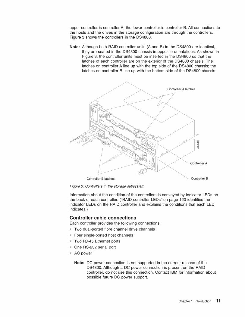
upper controller is controller A; the lower controller is controller B. All connections to
the hosts and the drives in the storage configuration are through the controllers.
Figure 3 shows the controllers in the DS4800.
Note: Although both RAID controller units (A and B) in the DS4800 are identical,
they are seated in the DS4800 chassis in opposite orientations. As shown in
Figure 3, the controller units must be inserted in the DS4800 so that the
latches of each controller are on the exterior of the DS4800 chassis. The
latches on controller A line up with the top side of the DS4800 chassis; the
latches on controller B line up with the bottom side of the DS4800 chassis.
Information about the condition of the controllers is conveyed by indicator LEDs on
the back of each controller. (“RAID controller LEDs” on page 120 identifies the
indicator LEDs on the RAID controller and explains the conditions that each LED
indicates.)
Controller cable connections
Each controller provides the following connections:
v Two dual-ported fibre channel drive channels
v Four single-ported host channels
v Two RJ-45 Ethernet ports
v One RS-232 serial port
v AC power
Note: DC power connection is not supported in the current release of the
DS4800. Although a DC power connection is present on the RAID
controller, do not use this connection. Contact IBM for information about
possible future DC power support.
Controller A
Controller B
Controller A latches
Controller B latches
ds48014
Figure 3. Controllers in the storage subsystem
Chapter 1. Introduction 11

Figure 4 identifies the connectors on the back of each controller.
Dual-ported drive channels
Each controller has two drive channels; each drive channel has two fibre
channel ports. The drive channels are used to connect storage expansion
enclosures to the RAID controllers on the DS4800.
Note: Other DS4000 product documentation might refer to the drive
channel ports as expansion ports.
Attention: The DS4800 requires the attachment of at least one DS4000
storage expansion enclosure populated with at least two drives to be
operational. Without being connected to at least one DS4000 storage
expansion enclosure populated with at least two drives, the DS4800
controller will not successfully complete the power-on process.
Two drive channels (one from each controller) are used to form a redundant
drive channel pair. Each drive channel pair supports up to a maximum of
112 drives in seven or eight IBM DS4000 storage expansion enclosures,
depending on the enclosure types. (See Table 4 on page 9 for more
information.)
The drive channel port speeds are auto-negotiated between 2 Gbps and 4
Gbps fibre channel speeds. Both ports of a dual-ported drive channel must
be connected to storage expansion enclosures operating at the same fibre
channel speed. In addition, link-speed negotiation for a given port is limited
to the link speeds supported by the Small Form-factor Pluggable (SFP)
module plugged in that port.
However, if the 2 Gbps and the 4 Gbps DS4000 storage expansion
enclosures are separated into different redundant drive channel pairs, the
DS4800 (�1�) will support both 2 Gbps and the 4 Gbps DS4000 storage
expansion enclosures at their own fibre channel speed (either 2 Gbps or 4
Gbps). For example, as shown in Figure 5 on page 13, the redundant drive
Host channels
RS-232serial port
Ethernet ports Dual-porteddrive channels
ACpower DC
power
Host channels
RS-232serial portEthernet ports
Dual-porteddrive channels
ACpowerDC
power
Controller A
Controller B
Strain-reliefclamp
Strain-reliefclamp
ds48015
Figure 4. Controller connections
12 IBM System Storage DS4800 Storage Subsystem: Installation, User’s, and Maintenance Guide
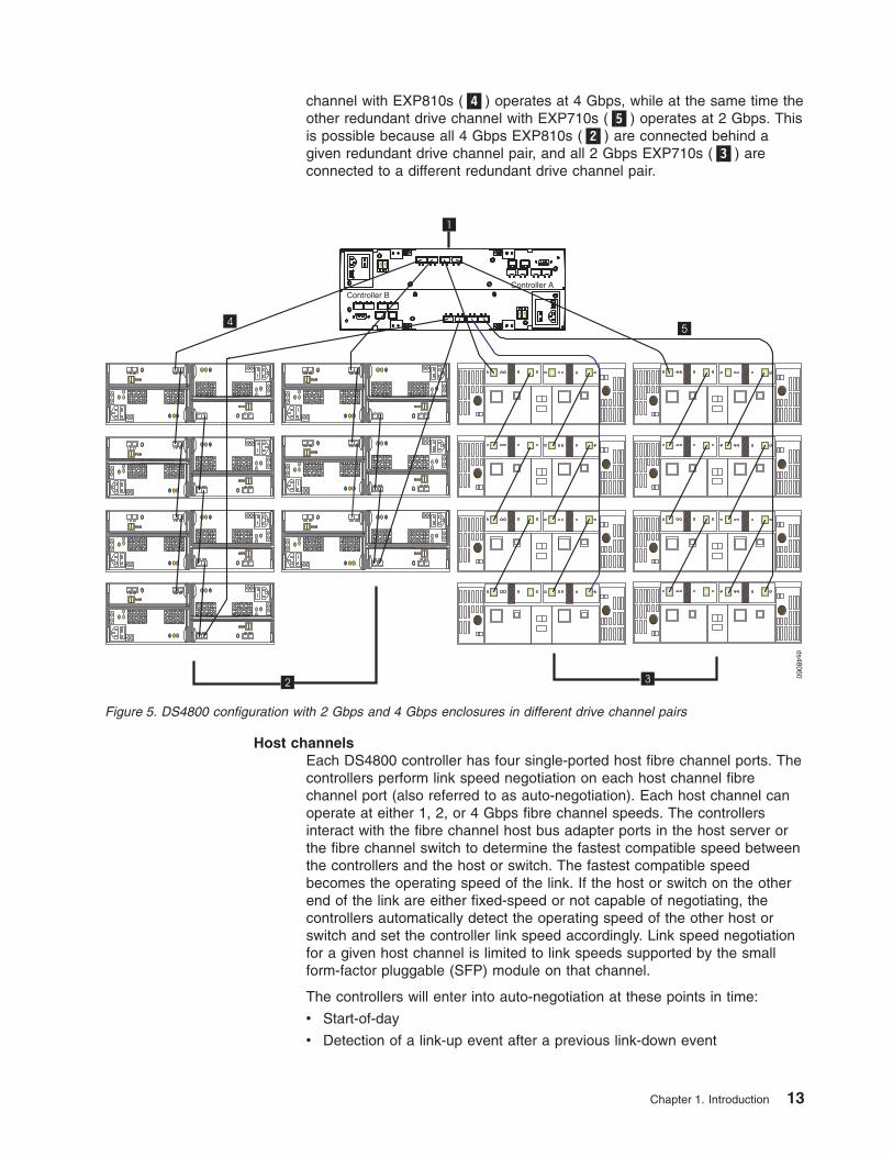
channel with EXP810s (�4�) operates at 4 Gbps, while at the same time the
other redundant drive channel with EXP710s (�5�) operates at 2 Gbps. This
is possible because all 4 Gbps EXP810s (�2�) are connected behind a
given redundant drive channel pair, and all 2 Gbps EXP710s (�3�) are
connected to a different redundant drive channel pair.
Host channels
Each DS4800 controller has four single-ported host fibre channel ports. The
controllers perform link speed negotiation on each host channel fibre
channel port (also referred to as auto-negotiation). Each host channel can
operate at either 1, 2, or 4 Gbps fibre channel speeds. The controllers
interact with the fibre channel host bus adapter ports in the host server or
the fibre channel switch to determine the fastest compatible speed between
the controllers and the host or switch. The fastest compatible speed
becomes the operating speed of the link. If the host or switch on the other
end of the link are either fixed-speed or not capable of negotiating, the
controllers automatically detect the operating speed of the other host or
switch and set the controller link speed accordingly. Link speed negotiation
for a given host channel is limited to link speeds supported by the small
form-factor pluggable (SFP) module on that channel.
The controllers will enter into auto-negotiation at these points in time:
v Start-of-day
v Detection of a link-up event after a previous link-down event
58
8 5
Controller AController B
2 3
1
45
ds48060
Figure 5. DS4800 configuration with 2 Gbps and 4 Gbps enclosures in different drive channel pairs
Chapter 1. Introduction 13

If the auto-negotiation process fails, the controllers will consider the link to
be down until negotiation is again attempted at one of these points in time.
For a 4 Gbps controller, the supported host-channel link speeds are 1, 2,
and 4 Gbps.
Ethernet ports
The Ethernet connections provide for out-of-band management
configurations to a host. The Ethernet ports are used for an RJ-45
10BASE-T or 100BASE-T Ethernet connection to each controller. Use the
Ethernet connection to directly manage the DS4800.
Use one Ethernet port for daily management of the DS4800. Reserve the
other port for use by service personnel or for subsystem monitoring
hardware that may be available in the future.
The two Ethernet ports must be connected into networks with two separate
subnet masks. Otherwise, the following Recovery Guru error will be
generated:
Ethernet Configuration conflict. Both Ethernet ports for a given DS4800
controller have been assigned IP addresses from the same subnet.
You can also make out-of-band management connections to the DS4800
controllers using the default IP addresses. The default IP addresses for the
controller A Ethernet ports 1 and 2 are 192.168.128.101 and
192.168.129.101, respectively. The default IP addresses for the controller B
Ethernet ports 1 and 2 are 192.168.128.102 and 192.168.129.102,
respectively. The default subnet mask for all four Ethernet ports is
255.255.255.0. See “Setting up IP addresses for DS4000 storage
controllers” for more information.
RS-232 serial port
The RS-232 serial connection provides a diagnostic port for use by service
personnel only to perform diagnostic operations on the RAID controllers.
Attention: Incorrect use of the serial port can result in loss of data access
and, in some cases, in loss of data. Do not make any connections to the
serial port unless you do so under the direct guidance of IBM support
personnel.
Note: The maximum baud rate is 115 200 bps. The default baud rate
setting from the factory is 38 400 bps.
Setting up IP addresses for DS4000 storage controllers
After you install DS4000 Storage Manager (as described in the DS4000 Storage
Manager Installation and Support Guide for your host operating system), complete
one of the following procedures to set up IP addresses:
v “Steps for setting up the DHCP/BOOTP server and network”
v “Steps for assigning static TCP/IP addresses to the DS4000 controllers” on page
15
Steps for setting up the DHCP/BOOTP server and network: To complete this
procedure, you must have the following components:
v A DHCP or BOOTP server
v A network management station (NMS) for Simple Network Management Protocol
(SNMP) traps
v A host that is connected to a storage subsystem through a fibre-channel I/O path
14 IBM System Storage DS4800 Storage Subsystem: Installation, User’s, and Maintenance Guide
||||
|
||
||
|
||
|

v A management station that is connected by an Ethernet cable to the storage
subsystem controllers
Note: You can avoid DHCP/BOOTP server and network tasks either by using the
default controller IP addresses, or by assigning static IP addresses to the
controller, as described in the next section.
Complete the following steps to set up the DHCP/BOOTP server and network:
1. Get the MAC address from each controller blade.
2. Complete whichever of the following steps is appropriate for your server:
v On a DHCP server, create a DHCP record for each of the MAC addresses.
Set the lease duration to the longest time possible.
v On a BOOTP server, edit the bootptab file to add in the entries that associate
the MAC address tab with the TCP/IP address.
3. Connect the DS4000 storage subsystem Ethernet ports to the network.
4. Boot the DS4000 storage subsystem.
The DHCP server automatically assigns new IP addresses to the controller Ethernet
port.
Steps for assigning static TCP/IP addresses to the DS4000 controllers: To
complete this procedure, you must have the following components:
v A host that is connected to a storage subsystem through a fibre-channel I/O path
v A management station that is connected by an Ethernet cable to the storage
subsystem controllers
Complete the following steps to assign static TCP/IP addresses to the DS4000
storage subsystem controllers, using default TCP/IP addresses that are assigned to
the DS4000 storage subsystem controllers during manufacturing:
1. Make a direct management connection to the DS4000 storage subsystem, using
the default TCP/IP addresses:
v Controller A: 192.168.128.101
v Controller B: 192.168.128.102
v Subnet Mask: 255.255.255.0
Note: For a DS4000 subsystem that has two Ethernet ports per controller, such
as the DS4200, DS4700 and DS4800, use the Ethernet port that is
labeled #1.
2. Start the DS4000 Storage Manager client software. The Enterprise Management
window opens.
3. Add the DS4000 subsystem to the DS4000 Enterprise Management domain
using the default IP addresses.
4. In the Enterprise Management window, click on the name of the default storage
subsystem. The Subsystem Management window opens.
5. In the Subsystem Management window, right-click the controller icon and select
Change —> Network Configuration in the pull-down menu. The Change
Network Configuration window opens.
6. In the Change Network Configuration window, click on the Controller A and
Controller B tabs and type the new TCP/IP addresses in their appropriate fields.
Click OK.
7. Close the Subsystem Management window, wait at least five minutes, then
delete the default DS4000 storage subsystem entry in the Enterprise
Chapter 1. Introduction 15
||
|||
|
|
|
||
||
|
|
||
||
|
||
|||
||
|
|
|
|||
||
||
||
|||
|||
||

Management window. The default DS4000 storage subsystem entry still
displays, but shows an “unresponsive” icon.
8. If applicable, change the IP address of the Ethernet port in the management
station to a value that is on the same TCP/IP subnet as the controller Ethernet
port IP addresses that you just assigned. Exit DS4000 Storage Manager, then
restart.
9. Add a new storage subsystem entry in the Enterprise Management window,
using the new assigned IP addresses.
Note: To manage storage subsystems through a firewall, configure the firewall to
open port 2463 to TCP data.
Controller memory
Each RAID controller has up to 8 GB of data cache memory, for a total of up to 16
GB cache memory per DS4800. Each RAID controller also has a total of either 512
MB (for models 80A/H, 82A/H or 84A/H) or 1024 MB (for models 88A/H) of Intel
Pentium Xeon processor memory. The processor memory stores the controller
firmware, while the data cache is a buffer used to temporarily store hard disk drive
data during data read and write operations. A Cache Active LED on the controller
turns on when the cache contains data that has not been written to hard disk
drives. The Cache Active LED turns off when the cache does not contain unwritten
data.
Table 6 lists the technical specifications for the RAID controllers.
Table 6. RAID controller specifications
Category Criteria Specification
Memory Cache size 2 GB, 4 GB or 8 GB,
depending on the model
Interface Fibre channel host port 4 fiber-optic ports per
controller
2 Ethernet ports per controller
(for out-of-band management)
Fibre channel drive expansion
port
4 fiber-optic ports per
controller
Note: Each DS4800
controller drive channel has
two ports. There are two drive
channels per DS4800
controller.
Storage Expansion Enclosure
Support
Redundant drive channel
pairs
2 per controller
Maximum number of drives
per redundant drive channel
pair
112 drives per redundant
drive channel pair (either 8
storage expansion enclosures
with 14 drives each or 7
storage expansion enclosures
with 16 drives each). See
Table 4 on page 9.
Maximum number of drives
supported by one DS4800
224 drives (2 redundant drive
channel pairs with 112 drives
in each drive channel pair)
16 IBM System Storage DS4800 Storage Subsystem: Installation, User’s, and Maintenance Guide
||
||||
||
||
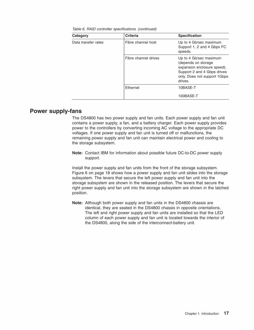
Table 6. RAID controller specifications (continued)
Category Criteria Specification
Data transfer rates Fibre channel host Up to 4 Gb/sec maximum.
Support 1, 2 and 4 Gbps FC
speeds.
Fibre channel drives Up to 4 Gb/sec maximum
(depends on storage
expansion enclosure speed).
Support 2 and 4 Gbps drives
only. Does not support 1Gbps
drives.
Ethernet 10BASE-T
100BASE-T
Power supply-fans
The DS4800 has two power supply and fan units. Each power supply and fan unit
contains a power supply, a fan, and a battery charger. Each power supply provides
power to the controllers by converting incoming AC voltage to the appropriate DC
voltages. If one power supply and fan unit is turned off or malfunctions, the
remaining power supply and fan unit can maintain electrical power and cooling to
the storage subsystem.
Note: Contact IBM for information about possible future DC-to-DC power supply
support.
Install the power supply and fan units from the front of the storage subsystem.
Figure 6 on page 18 shows how a power supply and fan unit slides into the storage
subsystem. The levers that secure the left power supply and fan unit into the
storage subsystem are shown in the released position. The levers that secure the
right power supply and fan unit into the storage subsystem are shown in the latched
position.
Note: Although both power supply and fan units in the DS4800 chassis are
identical, they are seated in the DS4800 chassis in opposite orientations.
The left and right power supply and fan units are installed so that the LED
column of each power supply and fan unit is located towards the interior of
the DS4800, along the side of the interconnect-battery unit.
Chapter 1. Introduction 17

Information about the condition of the power supplies, fans, and battery charger is
conveyed by indicator lights (LEDs) on the front of each of the power supply and
fan units and on the interconnect-battery unit. You must remove the front bezel to
see the LEDs. (“Power supply-fan LEDs” on page 125 identifies the indicator LEDs
on a power supply and fan unit and explains the conditions that each LED
indicates.)
Note: The order of the LEDs on the power supply and fan unit is different
depending on whether the power supply and fan unit is installed in the left or
right bay.
In the DS4800 Storage Subsystem, the right power supply and fan unit is linked to
controller A, and the left power supply and fan unit is linked to controller B. To
increase protection against power loss, always make sure that both power supply
and fan units are operational.
Interconnect-battery unit
The interconnect-battery unit is a removable midplane that provides cross-coupled
signal connection between the controllers. The control output from each controller is
connected to the control input in the alternate controller. An audible alarm is
mounted on the interconnect-battery unit display board. A mute switch for the
audible alarm is also mounted on the same board. The interconnect-battery unit
also provides the electrical communication path between the power supply and fan
units and allows their power supplies to load-share and to charge the cache-backup
battery packs. There are two cache-backup battery packs mounted inside the
interconnect-battery unit.
Latch
LatchPower supply-fans
Levers inreleasedposition
Levers inlatchedposition
ds48016
Figure 6. Power supply-fan
18 IBM System Storage DS4800 Storage Subsystem: Installation, User’s, and Maintenance Guide
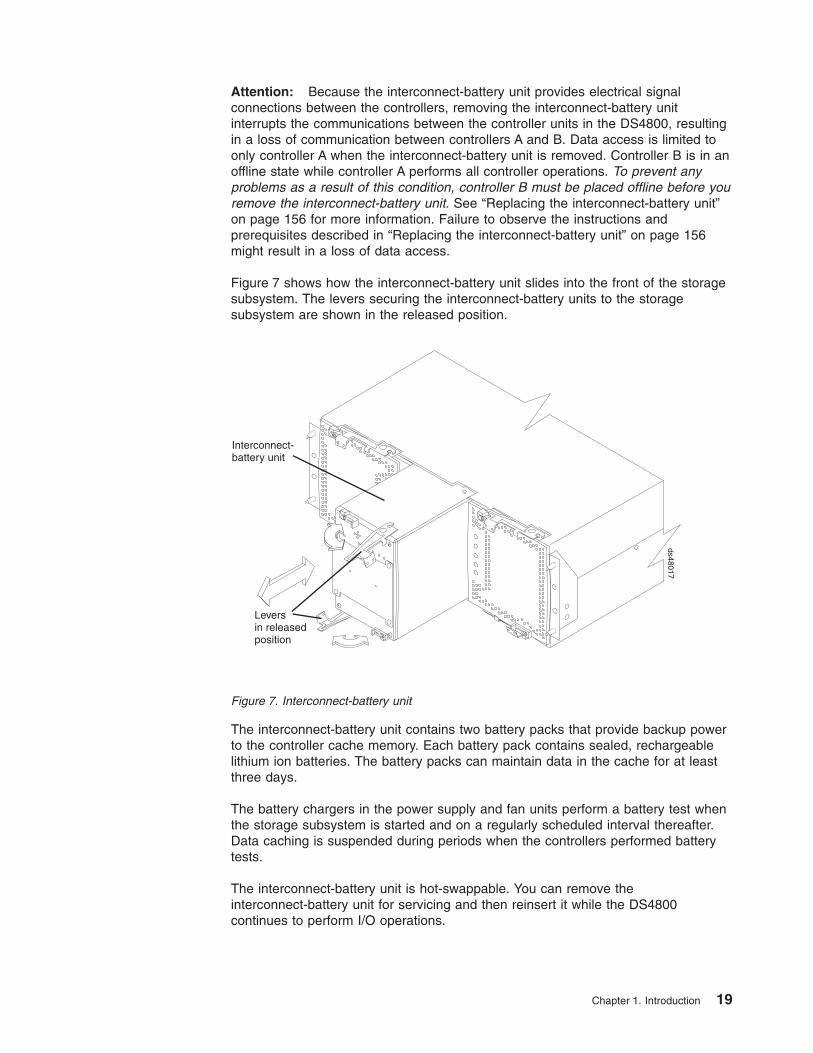
Attention: Because the interconnect-battery unit provides electrical signal
connections between the controllers, removing the interconnect-battery unit
interrupts the communications between the controller units in the DS4800, resulting
in a loss of communication between controllers A and B. Data access is limited to
only controller A when the interconnect-battery unit is removed. Controller B is in an
offline state while controller A performs all controller operations. To prevent any
problems as a result of this condition, controller B must be placed offline before you
remove the interconnect-battery unit. See “Replacing the interconnect-battery unit”
on page 156 for more information. Failure to observe the instructions and
prerequisites described in “Replacing the interconnect-battery unit” on page 156
might result in a loss of data access.
Figure 7 shows how the interconnect-battery unit slides into the front of the storage
subsystem. The levers securing the interconnect-battery units to the storage
subsystem are shown in the released position.
The interconnect-battery unit contains two battery packs that provide backup power
to the controller cache memory. Each battery pack contains sealed, rechargeable
lithium ion batteries. The battery packs can maintain data in the cache for at least
three days.
The battery chargers in the power supply and fan units perform a battery test when
the storage subsystem is started and on a regularly scheduled interval thereafter.
Data caching is suspended during periods when the controllers performed battery
tests.
The interconnect-battery unit is hot-swappable. You can remove the
interconnect-battery unit for servicing and then reinsert it while the DS4800
continues to perform I/O operations.
Leversin releasedposition
Interconnect-battery unit
ds48017
Figure 7. Interconnect-battery unit
Chapter 1. Introduction 19

Attention
Never remove the interconnect-battery unit unless directed to do so by an IBM
support representative. Removing the interconnect-battery unit after a
controller or a power supply and fan unit has already been removed results in
a loss of data access. Refer to “Replacing the interconnect-battery unit” on
page 156 for complete information about the conditions required for safe
removal of the interconnect-battery unit. Do not replace the
interconnect-battery unit without first meeting the requirements described in
“Replacing the interconnect-battery unit” on page 156.
Information about the condition of the interconnect-battery unit is conveyed by
indicator LEDs on the front of interconnect-battery unit. (“Interconnect-battery unit
LEDs” on page 127 identifies the indicator LEDs on the interconnect-battery unit
and explains the conditions that each LED indicates.)
You must remove the front bezel in order to see all of the interconnect-battery unit
LEDs. With the bezel in place, only the following interconnect-battery unit LEDs are
visible:
v Power
v Overall DS4800 Configuration Needs Attention
v Locate/Identify
Note: The displayed order of the Overall DS4800 Configuration Needs Attention
and Locate/Identify LEDs on the interconnect-battery unit are reversed when
the bezel is removed. See “Front bezel LEDs” on page 118 and
“Interconnect-battery unit LEDs” on page 127.
SFP modules
The storage subsystem supports fiber-optic interface cables. A small form-factor
pluggable (SFP) module must be installed in each interface connector on the
controller where a fiber-optic cable is to be installed.
Figure 8 shows an SFP module with fiber-optic cable. Note that the SFP module
shown might look different from those shipped with your unit. The differences do not
affect module performance.
Attention: Currently, the DS4800 supports only short-wave/multimode SFPs. In
DS4800 configurations, you may use long-wave SFPs only in fibre channel switches
that connect DS4800s over long distances. In addition, there are not any visual
markings to identify the maximum operating speeds of the SPFs aside from the
option and FRU part number on the SFP label.
SFP Module Fibre-optic cable
ds48018
Figure 8. SFP module with fiber-optic cable
20 IBM System Storage DS4800 Storage Subsystem: Installation, User’s, and Maintenance Guide
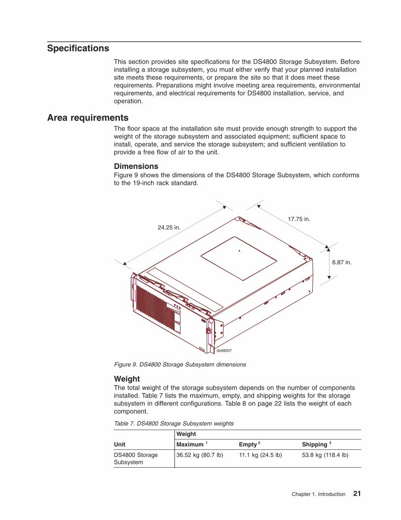
Specifications
This section provides site specifications for the DS4800 Storage Subsystem. Before
installing a storage subsystem, you must either verify that your planned installation
site meets these requirements, or prepare the site so that it does meet these
requirements. Preparations might involve meeting area requirements, environmental
requirements, and electrical requirements for DS4800 installation, service, and
operation.
Area requirements
The floor space at the installation site must provide enough strength to support the
weight of the storage subsystem and associated equipment; sufficient space to
install, operate, and service the storage subsystem; and sufficient ventilation to
provide a free flow of air to the unit.
Dimensions
Figure 9 shows the dimensions of the DS4800 Storage Subsystem, which conforms
to the 19-inch rack standard.
Weight
The total weight of the storage subsystem depends on the number of components
installed. Table 7 lists the maximum, empty, and shipping weights for the storage
subsystem in different configurations. Table 8 on page 22 lists the weight of each
component.
Table 7. DS4800 Storage Subsystem weights
Unit
Weight
Maximum
1 Empty
2 Shipping
3
DS4800 Storage
Subsystem
36.52 kg (80.7 lb) 11.1 kg (24.5 lb) 53.8 kg (118.4 lb)
6.87 in.
24.25 in.17.75 in.
ds48007
Figure 9. DS4800 Storage Subsystem dimensions
Chapter 1. Introduction 21

Table 7. DS4800 Storage Subsystem weights (continued)
Unit
Weight
Maximum
1 Empty
2 Shipping
3
1 Maximum weight indicates a storage subsystem with two battery modules installed. Each
battery module weighs 1.1 kg (2.5 lb).
2 Empty weight indicates a storage subsystem with all components removed.
3 Shipping weight indicates the maximum weight of the storage subsystem and all shipping
material.
Table 8. DS4800 Storage Subsystem component weights
Unit Weight
RAID controller 6.36 kg (14 lb)
Power supply-fan 3.72 kg (8.2 lb)
Interconnect-battery unit 5.36 kg (11.8 lb)
Battery module 1.134 kg (2.5 lb)
Shipping dimensions
Table 9 lists shipping carton dimensions. The height shown includes the height of
the pallet.
Table 9. DS4800 Storage Subsystem shipping carton dimensions
Height Width Depth
44.4 cm (17.5 in.) 62.2 cm (24.5 in.) 78.7 cm (31.0 in.)
Environmental requirements and specifications
This section describes the environmental conditions that are prerequisite to
installing the unit, and heat and sound conditions that are generated by normal
operation of the unit.
Temperature and humidity
Table 10 lists the acceptable temperature and humidity ranges in which the storage
subsystem is designed to operate.
Important: The recommended operating environment air temperature is 22° C (72°
F) or lower.
Table 10. Temperature and humidity requirements
Condition Parameter Requirement
Temperature
1 Operating range 10° - 35° C (50° - 95° F)
Maximum rate of change 10° C (18° F) per hour
Storage range 1° - 60° C (33° - 140° F)
Maximum rate of change 15° C (27° F) per hour
Transit range -40° C to 65° C (-40° F to
149° F)
Maximum rate of change 20° C (36° F) per hour
22 IBM System Storage DS4800 Storage Subsystem: Installation, User’s, and Maintenance Guide
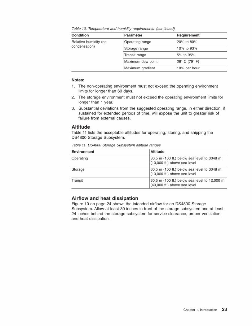
Table 10. Temperature and humidity requirements (continued)
Condition Parameter Requirement
Relative humidity (no
condensation)
Operating range 20% to 80%
Storage range 10% to 93%
Transit range 5% to 95%
Maximum dew point 26° C (79° F)
Maximum gradient 10% per hour
Notes:
1. The non-operating environment must not exceed the operating environment
limits for longer than 60 days.
2. The storage environment must not exceed the operating environment limits for
longer than 1 year.
3. Substantial deviations from the suggested operating range, in either direction, if
sustained for extended periods of time, will expose the unit to greater risk of
failure from external causes.
Altitude
Table 11 lists the acceptable altitudes for operating, storing, and shipping the
DS4800 Storage Subsystem.
Table 11. DS4800 Storage Subsystem altitude ranges
Environment Altitude
Operating 30.5 m (100 ft.) below sea level to 3048 m
(10,000 ft.) above sea level
Storage 30.5 m (100 ft.) below sea level to 3048 m
(10,000 ft.) above sea level
Transit 30.5 m (100 ft.) below sea level to 12,000 m
(40,000 ft.) above sea level
Airflow and heat dissipation
Figure 10 on page 24 shows the intended airflow for an DS4800 Storage
Subsystem. Allow at least 30 inches in front of the storage subsystem and at least
24 inches behind the storage subsystem for service clearance, proper ventilation,
and heat dissipation.
Chapter 1. Introduction 23

Table 12 lists the KVA, watts, and Btu calculations for the DS4800 Storage
Subsystem. These values assume the power supplies have a 73 percent efficiency
and a power factor of 0.99. These tabulated power and heat dissipation values are
typical for the storage subsystem. Maximum configuration units are typically
operated at higher data rates, have larger random access memory (RAM)
capacities, or have different host interface boards.
Table 12. DS4800 Storage Subsystem power and heat dissipation
Parameter KVA Watts (AC) Btu per hour
RAID controller .240 235 803.7
Shock and vibration requirements
Operational shock and operational vibration requirements are shown in this section.
Operational Shock: The DS4800 will be able to withstand the following shock.
Subjecting the equipment to a single shock pulse with the following characteristics
will simulate this level of shock:
v Velocity change = 20 inches per second
v Wave form = Triangular, 10g @3.75 ms
Operational Vibration (Random): While in its normal operating position, the
DS4800 will continue operating when subjected to a random vibration test using the
criteria shown in Table 13 on page 25. This test uses a dwell time of 15 minutes at
any frequency where vigorous or resonant excitation occurs.
ds48019
Figure 10. DS4800 Storage Subsystem airflow
24 IBM System Storage DS4800 Storage Subsystem: Installation, User’s, and Maintenance Guide
||
|||
|
|
||||

Table 13. DS4800 Storage Subsystem operational vibration specifications
Parameter Value
Frequency sweep 5 Hz - 150 Hz - 5 Hz
Wave form Sinusoidal, 0.25 g
Acoustic noise
Table 14 lists the maximum sound levels emitted by the storage subsystem.
Table 14. DS4800 Storage Subsystem sound levels
Measurement Level
Sound power (normal operation) 6.0 bels
Sound pressure (normal operation) 60 dBA
These levels are measured in controlled acoustical environments according to ISO
7779 and are reported in accordance with ISO 9296. The declared sound power
levels indicate an upper limit, below which a large portion of machines operate.
Sound pressure levels in your location might exceed the average 1-meter values
stated because of room reflections and other nearby noise.
Electrical requirements
This section provides information regarding site power and wiring, storage
subsystem AC power requirements, and power cord routing instructions.
Consider the following information when preparing the DS4800 Storage Subsystem
installation site:
v Protective ground – Site wiring must include a protective ground connection to
the AC power source.
Note: Protective ground is also known as safety ground or chassis ground.
v Circuit overloading – Power circuits and associated circuit breakers must provide
sufficient power and overload protection. To prevent possible damage to the unit,
isolate its power source from large switching loads (such as air conditioning
motors, elevator motors, and factory loads).
v Power failures – If a total power failure occurs, the unit automatically performs a
power-up recovery sequence without operator intervention after power is
restored.
Table 15. IBM System Storage DS4800 AC power requirements
Low Range High Range
Nominal Voltage 110 220
Voltage 90 to 132 VAC 198 to 264 VAC
Frequency (Hertz) 50 to 60 Hz 50 to 60 Hz
Minimum Operating Current 3.0 Aa 1.5 Ab
Maximum Operating Current 3.0 Aa 1.5 Ab
Maximum Surge Current 4.0 Aa 2.0 Ab
Chapter 1. Introduction 25
||
||
||
|||
|

Table 15. IBM System Storage DS4800 AC power requirements (continued)
Low Range High Range
a. Typical voltage: 120 V AC, 60 Hz, assumes 75% power-supply efficiency and 0.99 power
factor
b. Typical voltage: 240 V AC, 60 Hz, assumes 75% power-supply efficiency and 0.99 power
factor
Site wiring and power
The storage subsystem uses wide-ranging redundant power supplies that
automatically accommodate voltages to the AC power source. The power supplies
operate within the range of 90 VAC to 264 VAC, at a minimum frequency of 50 Hz
and a maximum frequency of 60 Hz. The power supplies meet standard voltage
requirements for both domestic (inside USA) and international (outside USA)
operation. They use standard industrial wiring with line-to-neutral or line-to-line
power connections.
The agency ratings for the DS4800 Storage Subsystem are 5 amps at 100 VAC
and 2.25 amps at 240 VAC. These are the overall maximum currents for this
system.
AC power recovery
After normal power is restored after a total AC power failure, the DS4800 Storage
Subsystem performs power-up recovery procedures automatically without operator
intervention.
Power cords and receptacles
The DS4800 ships with the line jumper cords used to connect the DS4800 to rack
power distribution units (PDUs). If you need the AC power cords to connect the
DS4800 to wall receptacle outlets, you must purchase the appropriate power cords
for your country or region as described in Appendix D, “Power cords,” on page 193.
26 IBM System Storage DS4800 Storage Subsystem: Installation, User’s, and Maintenance Guide

Chapter 2. Installing the storage subsystem
This chapter provides the information that you need to install the DS4800 into a
rack cabinet.
Before you begin the installation, review the safety information in “Safety” on page
iii.
Chapter 2, “Installing the storage subsystem” provides an overview of the entire
DS4800 installation process. Read this overview before you begin the installation.
Installation overview
Statement 4:
≥ 18 kg (39.7 lb) ≥ 32 kg (70.5 lb) ≥ 55 kg (121.2 lb)
CAUTION:
Use safe practices when lifting.
Attention: A fully configured DS4800 weighs 36.52 kg (80.7 lbs). For safety
reasons, the installation instructions in this chapter direct you to remove the
DS4800 components before removing the storage subsystem from the shipping box
and installing it in a rack cabinet.
The following steps summarize the DS4800 installation process. Each step below is
detailed in this chapter or in the next two chapters, Chapter 3, “Cabling the storage
subsystem” and Chapter 4, “Operating the storage subsystem.”
1. Review the preparation recommendations. See “Preparing for installation” on
page 30.
2. Prepare the installation site. See “Preparing the site” on page 32.
3. Prepare the rack cabinet. See “Preparing the rack cabinet” on page 32.
4. Fold down and open the sides of the shipping box. Without removing the
DS4800 from box, you can remove the DS4800 rack mounting rails and
hardware from the box, which is placed on the bottom of the shipping box
underneath the DS4800 enclosure. Install the support rails in the rack cabinet.
See “Installing the support rails” on page 33.
5. Before removing the DS4800 from the shipping box, remove the components
from the DS4800 chassis to lighten the unit. See “Removing the components”
on page 40.
© Copyright IBM Corp. 2006, 2007 27

6. Record the serial number, machine type and model number, and RAID
controller MAC addresses for your DS4800 Storage Subsystem in Appendix B,
“Records,” on page 187.
The serial number, machine type, and model number are located on top of
each the DS4800 subsystem unit. The MAC addresses are located near the
Ethernet ports on each RAID controller, as shown in Figure 103 on page 187.
You may not be able to easily access this information after you install the
DS4800.
7. Install and secure the DS4800 chassis in the rack cabinet. See “Installing the
DS4800 on the support rails” on page 42.
8. Replace the components in the installed DS4800 chassis. See “Replacing the
components” on page 44.
9. Install in the rack cabinet the DS4000 storage expansion enclosure or
enclosures you will cable to the DS4800. Follow the instructions in the
Installation, User’s, and Maintenance Guide for your DS4000 storage
expansion enclosure to set up and mount the storage expansion enclosures.
Attention
Before you power on the DS4800 Storage Subsystem, the DS4800 must
be cabled to at least one storage expansion enclosure populated with at
least two drives. If at least two drives are not installed in each attached
storage expansion enclosure when you power on the DS4800, your
standard storage partition key will be lost and will need to be regenerated
using instructions on the IBM DS4000 Solutions and Premium Features
Web site:
https://www-912.ibm.com/PremiumFeatures/
All drives in the connected storage expansion enclosure or enclosures
must contain no prior configuration data. Additionally, if at least two drives
are not installed in each attached storage expansion enclosure, the
resulting insufficient load to the storage expansion enclosure power
supply CRUs might cause the drive expansion enclosure power supply
CRUs to intermittently appear as failed and then reappear in an optimal
state, falsely indicating that the power supply CRUs are bad.
10. Use SFP modules and fibre channel cables to cable the DS4800 to the
DS4000 storage expansion enclosure or enclosures. See “Connecting storage
expansion enclosures to the DS4800” on page 59.
11. Set the enclosure IDs for all EXP100 and EXP710 storage expansion
enclosures in the configuration to unique values. The EXP810 drive expansion
enclosures automatically adjust the enclosure IDs to ensure unique enclosure
IDs among themselves. See “Storage expansion enclosure settings” on page
85.
12. Perform one of the following cabling tasks to enable management of the
DS4800 configuration:
v If you are using out-of-band management, cable the DS4800 Ethernet ports
to either the management workstation or the host. See “Connecting
secondary interface cables” on page 89.
v If you are using in-band management, cable the DS4800 host channels to
the fibre channel host bus adapters (HBAs) in either the hosts or the fibre
channel switch that connects to the host HBAs. See “Connecting hosts to
the DS4800” on page 87.
28 IBM System Storage DS4800 Storage Subsystem: Installation, User’s, and Maintenance Guide

13. Connect the power cables for the DS4800. See “Connecting the power cables”
on page 96.
14. Power on the attached storage expansion enclosures and the DS4800 Storage
Subsystem using the procedure described in “Turning on the storage
subsystem” on page 105.
15. Install the DS4000 Storage Manager host software on the management
workstation (for out-of-band management) or on the host (for in-band
management). Refer to the IBM System Storage DS4000 Storage Manager
Version 9 Installation and Support Guide for the appropriate operating system
for instructions on how to install the DS4000 Storage Manager host software.
16. Use the DS4000 Storage Manager host software to verify the configuration.
17. Review and perform the procedures described in “Performing the DS4000
Health Check process” on page 102.
Handling static-sensitive devices
Attention: Static electricity can damage electronic devices and your system. To
avoid damage, keep static-sensitive devices in their static-protective packages until
you are ready to install them.
To reduce the possibility of electrostatic discharge (ESD), observe the following
precautions:
v Limit your movement. Movement can cause static electricity to build up around
you.
v Handle the device carefully, holding it by its edges or its frame.
v Do not touch solder joints, pins, or exposed printed circuitry.
v Do not leave the device where others can handle and possibly damage the
device.
v While the device is still in its static-protective package, touch it to an unpainted
metal part of the system unit for at least two seconds. This drains static electricity
from the package and from your body.
v Remove the device from its package and install it directly into your system unit
without setting it down. If it is necessary to set the device down, place it in its
static-protective package. Do not place the device on your system unit cover or
on a metal table. Take additional care when handling devices during cold weather
because heating reduces indoor humidity and increases static electricity.
Heat output, airflow, and cooling
The maximum heat output of the DS4800 is 235 watts (803.7 BTU/hr). Each
DS4800 rack-mounted unit requires an airflow of 2.5 m3 (87 ft.3) per minute. The
input air temperature to all rack cabinets should be in the range 10° C - 35° C (50°
F - 95° F). The recommended operating temperature is 22° C (72° F).
When rack cabinets that contain many DS4800s are to be installed together, the
following requirements must be met to ensure that the DS4800s are adequately
cooled:
v Air enters at the front of the rack cabinet and leaves at the back. To prevent the
air that is leaving the rack cabinet from entering the intake of another piece of
equipment, you must position the rack cabinets in alternate rows, back-to-back
and front-to-front. This arrangement is known as cold aisle/hot aisle and is shown
in Figure 11 on page 30.
Chapter 2. Installing the storage subsystem 29
|||||

v Where rack cabinets are in rows, each rack cabinet must touch the rack cabinet
that is next to it. This reduces the amount of hot air that can flow around from the
back of the rack into the intakes of the storage subsystems that are in that rack
cabinet. You should use Suite Attach Kits to completely seal any gaps that
remain between the rack cabinets. For details about Suite Attach Kits, contact
your marketing representative.
v Where rack cabinets are in rows front-to-front or back-to-back, a gap of at least
1220 mm (48 in.) must separate the rows across the cold aisle.
v To ensure correct airflow in each rack cabinet, the rack filler plates must be
installed in unused positions. Also, all the gaps in the front of the rack cabinets
must be sealed, including the gaps between the storage subsystems.
Preparing for installation
Before installing the DS4800 Storage Subsystem, create a detailed plan of how this
unit will be used in your storage configuration. The plan should include determining
RAID levels, failover requirements, operating systems to be used, and total storage
capacity requirements.
Complete the following steps to prepare the DS4800 for installation into a rack
cabinet:
1. Prepare the site to meet all area, environmental, power, and site requirements.
For more information, see “Specifications” on page 21.
2. Move the shipping box that contains the DS4800 to the site.
Attention: The DS4800 shipping box weighs up to 53.8 kg (118.4 lb).
Cold aisle
Air
cond
ition
er
Hot aisle
back
front
back
back
front
Airflow
front2440 mm betweencenter lines of hotand cold aisle
Perforated tilesor gratings
1220 mm coldaisle width
T42 racks
T42 racks
T42 racks
f10
ug
00
1
Figure 11. Example of cold aisle/hot aisle rack cabinet configuration
30 IBM System Storage DS4800 Storage Subsystem: Installation, User’s, and Maintenance Guide

Statement 4:
≥ 18 kg (39.7 lb) ≥ 32 kg (70.5 lb) ≥ 55 kg (121.2 lb)
CAUTION:
Use safe practices when lifting.
3. Remove the mounting rails, mounting hardware, and line jumper cords from the
DS4800 shipping box. Do not remove the DS4800 from the shipping box at this
time.
Attention: The mounting rails, mounting hardware, and line jumper cords may
be packed beneath the DS4800 in the shipping box. To remove these items
from the shipping box without first removing the DS4800, open the two long
sides of the shipping box. Then open and fold flat the two short sides of the
shipping box. This enables you to access the mounting rails, mounting
hardware, and line jumper cords without first removing the DS4800 from the
shipping box.
After you open the DS4800 shipping container and remove the mounting rails,
mounting hardware, and line jumper cords, check the remaining contents (see
“Inventory checklist” on page 3) without removing the DS4800 from the shipping
box. If any items are missing, contact your IBM reseller before proceeding.
4. Assemble the tools and equipment that you will need for installation. These
include the following:
v Region-specific power cords required for the DS4800.
v 5/16 (8 mm) hex nut driver.
v Medium flat-blade screwdriver.
v Antistatic protection (such as a grounding wrist strap).
v Fibre channel and Ethernet interface cables and cable straps.
v SFP modules.
v The line cord jumper power cords that are shipped with the DS4800.
v The rack-mounting hardware that ships with the DS4800.
v The appropriate host software kit for your operating system.
Depending on the DS4800 model you order, your DS4800 will ship with either
the Microsoft Windows host software attachment kit or with your choice of
host software kits (Windows, AIX, Linux, Netware, SUN Solaris, HP-UX, Linux
on POWER, or VMware). The host software kit grants you permission to
attach host servers using the appropriate operating system to the DS4800.
The kit includes a DS4000 Storage Manager Version 9 Support CD that has
the appropriate IBM DS4000 Storage Manager host software. If you order
more than one host software kit, the additional kits may also be shipped in
the DS4800 shipping box.
Chapter 2. Installing the storage subsystem 31
||||

The CD also includes the DS4000 Storage Subsystem controller firmware.
Controller firmware version 6.23.xx.xx or higher, which supports the
attachment of EXP810, is on the DS4000 Storage Manager version 9.23
release 1 CD or can be downloaded from the IBM support Web site for
DS4000 storage products:
www.ibm.com/servers/storage/support/disk/
Note: Depending on your DS4800 model, you may need to purchase the
appropriate host software kit for your host server operating system.
Contact your IBM representative or reseller for more information.
5. Continue with “Preparing the site.”
Preparing the site
The floor area at the installation site must provide the following conditions:
v Sufficient space to install the DS4800.
v Enough stability to support the weight of the fully configured DS4800 and
associated systems. A fully configured DS4800 weighs 36.52 kg (80.7 lb).
Ensure that all requirements, such as floor space, air conditioning, and electrical
service, have been met. Other site preparation activities include the following tasks:
v To ensure that there is enough room to move around the cabinet and install
modules, clear space at the installation area.
v Install uninterruptible power supply (UPS) devices.
v If applicable, install host bus adapters (HBAs), switches, or other devices.
v Route interface cables from the hosts or switches to the installation area.
v Route main power cords to the installation area.
For information on interface cables and connections, see Chapter 3, “Cabling the
storage subsystem,” on page 47.
Continue with “Preparing the rack cabinet.”
Preparing the rack cabinet
Important: Before you install the DS4800 in a rack cabinet, keep in mind the
following considerations:
v Review the documentation that comes with your rack cabinet for safety and
cabling considerations.
v Install the DS4800 in a recommended 22° C (72° F) environment.
v To ensure proper airflow, do not block the air vents; at least 15 cm (6 in.) of air
space is required. Review the important information in “Heat output, airflow, and
cooling” on page 29.
v To ensure rack stability, load the rack cabinet starting at the bottom.
v If you install multiple components in the rack cabinet, do not overload the power
outlets.
v Always connect the storage subsystem to a properly grounded outlet.
v Always connect the IBM-certified rack power distribution units (PDUs) to at least
two independent power circuits or sources.
Complete the following steps to prepare the rack cabinet before you install the
DS4800:
1. Move, unpack, and level the rack cabinet at the installation site (if needed).
32 IBM System Storage DS4800 Storage Subsystem: Installation, User’s, and Maintenance Guide
|||||

2. Remove the external rack panels.
3. If necessary, stop all I/O activity to the devices in the rack cabinet.
4. If necessary, turn off all storage expansion enclosure and rack cabinet power.
Disconnect existing power, network, and other external cables.
5. Install any additional interface cables and power cables.
After you have completed these steps, continue with “Installing the support rails.”
Installing the support rails
Attention: Duplicate copies of the rack mounting templates are provided in
Appendix C, “Rack mounting templates,” on page 189. If you want to tear out the
templates from this document for easier use, use the copies provided in
Appendix C, “Rack mounting templates,” on page 189 instead of the copies in this
section.
Use the following templates and instructions to identify the proper locations for
inserting M5 screws when mounting the support rails and DS4800 to a rack cabinet.
The locations for the M5 screws are highlighted in the templates.
Hold the appropriate template up to each side of the rack cabinet at the 4–U
section where you will install the DS4800. The highlighted squares on each side of
the template mark the positions where you will thread the M5 screws that secure
the rails and the DS4800 to the front and rear of the cabinet.
The DS4800 is 4 U high. Align the template with the rack at a U boundary. U
boundaries are shown as horizontal dashed lines in the rack mounting templates.
Note: The mounting holes shown in the following rack mounting templates are
square. The holes in your rack might be round, square, or threaded. Use the
washers supplied under the heads of the M5 screws when mounting to racks
with square holes.
Chapter 2. Installing the storage subsystem 33
|||||
||
||||

ds48020DS4800FRONT
Rack MountingTemplate
0 U
2 U
3 U 3 U
2 U
1 U1 U
0 U
4 U4 U
Rail assembly(Front left)
Rail assembly(Front right)
Rail assembly(Front left)
Rail assembly(Front right)
Figure 12. DS4800 front rack mounting template
34 IBM System Storage DS4800 Storage Subsystem: Installation, User’s, and Maintenance Guide
|
|||
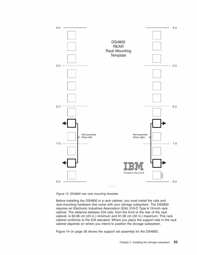
Before installing the DS4800 in a rack cabinet, you must install the rails and
rack-mounting hardware that come with your storage subsystem. The DS4800
requires an Electronic Industries Association (EIA) 310-D Type A 19-inch rack
cabinet. The distance between EIA rails, from the front to the rear of the rack
cabinet, is 60.96 cm (24 in.) minimum and 81.28 cm (32 in.) maximum. This rack
cabinet conforms to the EIA standard. Where you place the support rails in the rack
cabinet depends on where you intend to position the storage subsystem.
Figure 14 on page 36 shows the support rail assembly for the DS4800.
ds48021
DS4800REAR
Rack MountingTemplate
0 U
2 U
3 U 3 U
2 U
1 U1 U
0 U
4 U4 U
Rail assembly(Rear left)
Rail assembly(Rear right)
Printed in the U.S.A
Figure 13. DS4800 rear rack mounting template
Chapter 2. Installing the storage subsystem 35

Complete the following steps to install the support rails:
Note: Refer to Figure 14 while performing these steps.
1. Ensure that the rack cabinet has already been installed.
2. Ensure that a stabilizer has been correctly attached to the bottom front of the
rack cabinet to prevent the rack cabinet from tipping forward while the DS4800
is being installed.
Refer to the installation and service guide, or equivalent, for the rack cabinet
as required.
3. If you have not yet done so, remove the mounting rails, mounting hardware,
and line jumper cords from the DS4800 shipping box, which is on the bottom
of the shipping box beneath the DS4800 chassis. Do not remove the DS4800
from the shipping box at this time.
Attention: The mounting rails, mounting hardware, and line jumper cords
may be packed beneath the DS4800 in the shipping box. To remove these
items from the shipping box without first removing the DS4800, open the two
long sides of the shipping box. Then open and fold flat the two short sides of
the shipping box. This enables you to access the mounting rails, mounting
hardware, and line jumper cords without first removing the DS4800 from the
shipping box.
4. Locate the two support rails and six of the eight M5 screws that are supplied
with the DS4800.
5. The rack-mounted unit is four EIA units high. Decide accordingly where you
are going to install the support rails.
Attention: Use the rack mounting templates in this chapter or in Appendix C,
“Rack mounting templates,” on page 189 to locate the proper rack mounting
holes for installing the support rails into the rack cabinet.
Note the following considerations before you choose where to install the rails:
v Plan the installation so that each DS4800 subsystem and its associated
storage expansion enclosures are mounted together in the same rack, or in
adjacent racks if necessary.
v When you install the DS4800 and associated storage expansion enclosures
into a rack cabinet, install each device in the lowest available position and
work upwards so that the rack does not become unstable.
Rear rail hold-down clips(right clip not shown)
Flat head screws
Mounting rails
Alignment pins
ds48009
Mounting flange
Mounting flange
Figure 14. DS4800 support rail assembly
36 IBM System Storage DS4800 Storage Subsystem: Installation, User’s, and Maintenance Guide
|
|||

Note: If you are installing more than one DS4800 Storage Subsystem, it is
recommended that you install each DS4800 and its associated
storage expansion enclosures in a separate rack cabinet.
v If appropriate, allow for possible later installation of other units.
v If necessary, remove the rack power distribution units (PDUs) before you
install the support rails.
v For procedures and more information, refer to the installation and service
guide, or equivalent, for the rack cabinet.
6. Starting with the left rail, use a medium flat-blade screwdriver to loosen the two
flat-head rail adjustment screws. See Figure 14 on page 36.
7. Hold the front of the left rail against the inside of the front rack-mounting
flange, and then extend the rear of the support rail until it makes contact with
the rear rack mounting flange. The alignment pins at the rear of the rail should
slide into the holes at the rear of the rack.
8. From the front of the rack, with the rail mounting flanges inside of the front
rack-mounting flange, use the 5/16 (8 mm) hex nut driver to thread and loosely
tighten the lower M5 screw only. Use the front rack mounting template in this
chapter (or use the copy in Appendix C, “Rack mounting templates,” on page
189) to locate the proper rack mounting hole for installing this screw.
Attention: Do not completely tighten the screw until you have installed the
DS4800 in the rack cabinet.
9. From the rear of the rack, thread and loosely tighten two M5 screws using the
5/16 (8 mm) hex nut driver. Use the rear rack mounting template in this
chapter (or use the copy in Appendix C, “Rack mounting templates,” on page
189) to locate the proper rack mounting holes for installing these screws. Do
not completely tighten the screws until you have installed the DS4800 in the
rack cabinet.
When you are finished installing the left rail, the rail should be attached to the
cabinet using one M5 screw in the front and two M5 screws at the back. All
three M5 screws should be loosely tightened.
10. Repeat step 6 through step 9 for the right rail.
11. Tighten the rail adjustment screws on both rails.
12. Continue with “Installing the DS4800.”
Installing the DS4800
The DS4800 Storage Subsystem contains two controllers, two power supply and
fan units, and one interconnect-battery unit. The RAID controllers are located at the
back of the unit. The two power supply and fan units and the interconnect-battery
unit are located behind the front bezel.
Figure 15 on page 38 shows the front bezel of the DS4800 Storage Subsystem, a
front view without the cover, and a back view. Figure 15 on page 38 also shows the
locations of the components that are referenced during this installation procedure.
Chapter 2. Installing the storage subsystem 37
||||
|||||
||

Assemble these items before proceeding with the installation.
v Antistatic protection, such as a grounded wrist strap
v Cart or other surface to hold the DS4800 and its components
v Two M5 screws
v Tie wraps or other cable management devices (optional)
Releasing and locking a component lever
Each of the components in the DS4800 Storage Subsystem is held in place by two
locking levers. Each lever engages a pin on the DS4800 Storage Subsystem
enclosure to pull the component securely into the enclosure. Figure 16 on page 39
shows the lever, the latch that locks the lever into position, and the pin. The top
view shows the lever in the closed and locked position. The bottom view shows the
lever in the released position.
AC power switchController B
Controller A
Power supply-fanInterconnect-battery unit
Front cover
Power supply-fan
ds48023
Figure 15. DS4800 Storage Subsystem front views and back view
38 IBM System Storage DS4800 Storage Subsystem: Installation, User’s, and Maintenance Guide

In the following sections, you will need to remove and replace each of the
components. Use these steps to release and latch the levers on each component.
To release both latches on a component and remove the component, complete the
following steps:
1. Push the latches to the side until the latches release the levers.
2. Rotate both levers out simultaneously. When the levers are completely free of
the pins, place one hand under the component and use the levers to pull the
component from the DS4800 Storage Subsystem.
Note: See Table 7 on page 21 for a listing of the weights of each DS4800
Storage Subsystem component.
To replace a component and lock the latches, complete the following steps:
1. With the levers perpendicular to the face of the component, slide the back of the
component into the appropriate slot.
2. Push the component into the slot and, when the component is almost fully
installed, ensure that the notches in the levers are aligned with the pins on the
enclosure.
Note: Do not force fit. The components are keyed to prevent them from being
inserted into the chassis incorrectly.
3. Holding the levers, press the component fully into the slot, engaging the pins on
the enclosure.
Latch
Lever
Pin
ds48024
Figure 16. Component lever and latch
Chapter 2. Installing the storage subsystem 39

4. Hold open both latches and rotate both levers simultaneously to the closed
position. Release the latches. When you release the latches, you should see
both latches slide over the levers, indicating that the component is locked in
place.
Removing the components
This section provides procedures for removing components from the DS4800 before
lifting it from the shipping box and placing the DS4800 in the cabinet. Removing
components from a DS4800 Storage Subsystem makes the storage subsystem
lighter and easier to lift from the shipping box and install in the rack cabinet. Place
the components on a dry, level, and static-free surface to protect them from
electrostatic discharge after you remove them from the DS4800.
Use these instructions after you have completed all applicable site, rack cabinet,
and DS4800 preparations (as discussed in “Preparing for installation” on page 30)
and installed the support rails (as discussed in “Installing the support rails” on page
33).
You will need an antistatic wrist strap and a cart or level surface (to hold the
components). Observe the precautions listed in “Handling static-sensitive devices”
on page 29. In the following procedure, you will remove the following components
from the storage subsystem before you install it in the rack cabinet:
v RAID controllers
v Power supply-fan units
v Interconnect-battery unit
Statement 4:
≥ 18 kg (39.7 lb) ≥ 32 kg (70.5 lb) ≥ 55 kg (121.2 lb)
CAUTION:
Use safe practices when lifting.
Attention: A fully populated DS4800 Storage Subsystem weighs 36.52 kg (80.7
lb). Do not attempt to lift the DS4800 Storage Subsystem from the shipping box or
install the unit in the rack cabinet unless all of the components have been removed.
If you choose to lift the DS4800 Storage Subsystem from the shipping box or install
the unit in the rack without removing all of the components first, you do so at your
own risk. For more information on the weights of the individual DS4800 Storage
Subsystem components, see “Specifications” on page 21.
40 IBM System Storage DS4800 Storage Subsystem: Installation, User’s, and Maintenance Guide
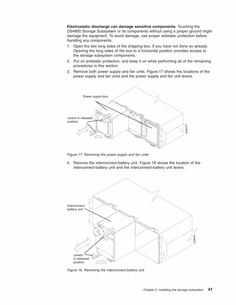
Electrostatic discharge can damage sensitive components. Touching the
DS4800 Storage Subsystem or its components without using a proper ground might
damage the equipment. To avoid damage, use proper antistatic protection before
handling any components.
1. Open the two long sides of the shipping box, if you have not done so already.
Opening the long sides of the box to a horizontal position provides access to
the storage subsystem components.
2. Put on antistatic protection, and keep it on while performing all of the remaining
procedures in this section.
3. Remove both power supply and fan units. Figure 17 shows the locations of the
power supply and fan units and the power supply and fan unit levers.
4. Remove the interconnect-battery unit. Figure 18 shows the location of the
interconnect-battery unit and the interconnect-battery unit levers.
Power supply-fans
Levers in releasedposition
ds48026
Figure 17. Removing the power supply and fan units
Interconnect-battery unit
Leversin releasedposition
ds48027
Figure 18. Removing the interconnect-battery unit
Chapter 2. Installing the storage subsystem 41

5. At the back of the DS4800 Storage Subsystem, use an adhesive note to label
each of the controllers. Controller A is in the upper slot; controller B is in the
lower slot. Figure 19 shows the locations of the controllers and controller levers.
6. Remove the controllers. Figure 19 shows the controller locations and the
controller levers.
7. After you have removed the components, record the serial number, machine
type and model number, and MAC addresses for your DS4800 Storage
Subsystem in Appendix B, “Records,” on page 187. The serial number, machine
type, and model number are located on top of each RAID controller unit. The
MAC addresses are located near the Ethernet ports on each RAID controller, as
shown in Figure 103 on page 187. You may not be able to easily access this
information after you install the DS4800.
8. Go to “Installing the DS4800 on the support rails.”
Installing the DS4800 on the support rails
This section provides instructions on how to install the DS4800 in a rack cabinet.
Attention: If you have not yet done so, record the serial number, machine type
and model number, and MAC addresses for your DS4800 Storage Subsystem in
Appendix B, “Records,” on page 187, as described in step 7.
Use the following procedure to install the DS4800 Storage Subsystem on support
rails in a rack cabinet. To mount a storage subsystem in the rack cabinet, all
support rails must be installed in their correct locations. If you need to install the
rails, see “Installing the support rails” on page 33.
CAUTION:
Never install components or other equipment in the top half of a rackmount
cabinet while the bottom half is empty. Doing so can cause the cabinet to
become top-heavy and to tip over. Always install hardware in the lowest
available position in the cabinet.
RAIDcontroller A
Leversin released position
RAIDcontroller B
ds48028
Figure 19. Removing the controllers
42 IBM System Storage DS4800 Storage Subsystem: Installation, User’s, and Maintenance Guide

Before installing the storage subsystem in the cabinet, ensure that there are no
obstructions, either in the cabinet or outside the cabinet, that would make ready
removal and replacement of any of the components impossible. Check for
obstructions at the front and rear of the cabinet.
Operational Shock
The DS4000 product will be able to withstand a free-fall drop from 0.5
inches onto a hard surface. Subjecting the equipment to a single shock
pulse with the following characteristics will simulate this level of shock:
Velocity change = 20 inches per second ; Wave form = Triangular,25g
@3.75 ms
Operational Vibration (Sweep)
While in its normal operating position, the DS4800 will continue operating
when subjected to the following vibration sweep. The test will include a
dwell time of 15 minutes at any frequency where vigorous or resonant
excitation occurs.
v Frequency sweep = 5 Hz – 150 Hz – 5 Hz
v Wave form = Sinusoidal, 0.25g
Attention: If you have removed the components from the DS4800, you should be
able to lift the unit from the shipping box and into the cabinet with the help of one
other person. (If you have not removed the components before the installation, you
should have at least two other people available to help you lift the unit from the
shipping box and into the rack cabinet.) For safety reasons, IBM does not
recommend moving the DS4800 Storage Subsystem from the shipping box and
installing the DS4800 on the support rails without first removing all CRU
components.
1. Remove the empty DS4800 Storage Subsystem from the shipping box and set
the storage subsystem in the cabinet. Figure 20 on page 44 shows the correct
orientation of the empty storage subsystem to the cabinet and support rail.
The following steps will help you safely install the DS4800 on the support rails:
a. If you have installed a screw in the upper mounting hole at the front of each
support rail, remove the upper screws. These two screws are used later to
secure the front of the storage subsystem to the rack.
b. Move the empty storage subsystem from the shipping box and to the front of
the cabinet.
c. With help from another person, place the back of the storage subsystem on
the support rails, and then slide the storage subsystem into the cabinet.
Attention: When you slide the storage subsystem into the cabinet, verify
that the back of the DS4800 Storage Subsystem is secured by the
hold-down clips located at the back of each rail. With the M5 rail screws
loosely threaded, you can make minor adjustments to the rails to ensure that
the subsystem latches in the hold-down clips. The hold-down clips are
shown in Figure 14 on page 36.
Chapter 2. Installing the storage subsystem 43

2. Secure the storage subsystem to the cabinet. Figure 20 shows how to secure
the DS4800 to the vertical members of the cabinet.
The following steps will help you safely secure the DS4800 in the rack cabinet:
a. Align the front mounting holes on the storage subsystem flanges with the
mounting holes on the cabinet.
b. Using the 5/16 (8 mm) hex nut driver, insert one M5 screw into the hole on
each flange, and tighten the screws completely to secure the front of the
storage subsystem to the cabinet.
3. At the front and the rear of the rack cabinet, use the 5/16 (8 mm) hex nut driver
to finish tightening the other three M5 screws for each rail.
4. Continue with “Replacing the components.”
Replacing the components
Complete the following procedure to replace the components in the storage
subsystem:
1. Replace the power supply and fan units. Figure 21 on page 45 shows the
locations and correct orientation of the power supply and fan units and the
power supply and fan unit levers. The power supply and fan units are keyed to
always fit into the enclosure in the proper orientation. When the component is
oriented correctly, a relief along one edge of each component aligns with a
ledge in the enclosure. Before installing the component, turn the component so
that the indicator LEDs are near the center of the storage subsystem.
ScrewMounting hole Support rail
ds48029
Figure 20. Securing the DS4800 to the rack cabinet
44 IBM System Storage DS4800 Storage Subsystem: Installation, User’s, and Maintenance Guide

2. Replace the interconnect-battery unit. Figure 22 shows the location of the
interconnect-battery unit and the interconnect-battery unit levers.
The interconnect-battery unit is keyed to always fit into the enclosure in the
proper orientation. A large pin located on the back of the component prevents
the component from being installed incorrectly. Before installing the component,
turn the component so that the LEDs are near the top of the component.
3. Replace the controllers at the back of the DS4800. Figure 23 on page 46 shows
the location of the controllers and the controller levers. Ensure that controller A
is returned to the upper slot and that controller B is returned to the lower slot.
Note: Controller B is installed in an orientation that is rotated 180 degrees from
that of controller A.
Power supply-fan
Levers inreleasedposition
Indicator LEDs
ds48030
Figure 21. Replacing the power supply and fan units
Leversin releasedposition
Interconnect-battery unit
ds48017
Figure 22. Replacing the interconnect-battery unit
Chapter 2. Installing the storage subsystem 45

4. Attach the DS4800 front bezel. Install the front bezel by aligning the pins on the
storage subsystem chassis with the spring-steel retainers on the cover, and then
press the cover toward the chassis until the pins snap into place. Figure 24
shows how to install the front bezel in the storage subsystem.
5. Continue with Chapter 3, “Cabling the storage subsystem,” on page 47.
RAIDcontroller A
Leversin released position
RAIDcontroller B
ds48028
Figure 23. Replacing the controllers
ds48025
Figure 24. Removing the front bezel
46 IBM System Storage DS4800 Storage Subsystem: Installation, User’s, and Maintenance Guide

Chapter 3. Cabling the storage subsystem
After the storage subsystem is installed in its permanent location, you must cable it
to hosts, drives, and other external devices, depending on your hardware
configuration. This chapter provides fibre channel and power cabling information for
the storage subsystem. It also provides information about configuring the storage
subsystem.
This chapter addresses the following cabling and configuration topics:
v “Working with SFPs and fiber-optic cables”
v “Connecting storage expansion enclosures to the DS4800” on page 59
v “Connecting hosts to the DS4800” on page 87
v “Connecting secondary interface cables” on page 89
v “Configuring the storage subsystem” on page 90
v “Installing the storage subsystem configuration” on page 96
v “Connecting the power cables” on page 96
Working with SFPs and fiber-optic cables
Each RAID controller has four single-ported host channel connections and two
dual-ported drive channel connections. You use a small-form factor pluggable
transceiver (SFP) to connect each host channel port and drive channel port to hosts
and storage expansion enclosures. The SFP is inserted into the port, and then a
fiber-optic cable is inserted into the SFP. The other end of the fiber-optic cable
connects to an external device. SFPs are laser products.
Statement 3
CAUTION:
When laser products (such as CD-ROMs, DVD drives, fiber optic devices, or
transmitters) are installed, note the following:
v Do not remove the covers. Removing the covers of the laser product could result in
exposure to hazardous laser radiation. There are no serviceable parts inside the
device.
v Use of controls or adjustments or performance of procedures other than those
specified herein might result in hazardous radiation exposure.
Danger
Some laser products contain an embedded Class 3A or Class 3B laser diode. Note the
following.
Laser radiation when open. Do not stare into the beam, do not view directly with optical
instruments, and avoid direct exposure to the beam.
© Copyright IBM Corp. 2006, 2007 47

Handling fiber-optic cables
Before you use fiber-optic cables, read the following precautions.
Attention: To avoid damage to the fiber-optic cables, follow these guidelines:
v Do not route the cable along a folding cable-management arm.
v When attaching to a device on slide rails, leave enough slack in the cable so that
it does not bend to a radius of less than 38 mm (1.5 in.) when extended or
become pinched when retracted.
v Route the cable away from places where it can be snagged by other devices in
the rack cabinet.
v Do not overtighten the cable straps or bend the cables to a radius of less than 38
mm (1.5 in.).
v Do not put excess weight on the cable at the connection point. Be sure that the
cable is well supported.
Installing SFP modules
The DS4800 host and drive channel ports require SFP modules. SFP modules are
used to convert electrical signals to optical signals that are required for fibre
channel transmission to and from RAID controllers. The DS4800 supports two types
of SFP modules: one with a plastic latch and one with a wire latch. After you install
the SFP modules, you use fiber-optic cables to connect the DS4800 to other fibre
channel devices.
Before you install SFP modules and fiber-optic cables, read the following
information:
v Use only short-wave/multimode SFPs in DS4800 host or drive ports. In DS4800
configurations, you may use long-wave SFPs only in fibre channel switches that
connect DS4800s over long distances.
v The SFP module housing has an integral guide key designed to prevent you from
inserting the SFP module improperly.
v Use minimal pressure when you insert the SFP module into a port. Forcing the
SFP module into a port could cause damage to the SFP module or the port.
v You can insert or remove the SFP module while the port is powered on.
v The operational loop performance is not affected when you install or remove an
SFP module.
v You must insert the SFP module into a port before you connect the fiber-optic
cable.
v You must remove the fiber-optic cable from the SFP module before you remove
the SFP module from the fibre channel port. See “Removing SFP modules” on
page 50 for more information.
v The speed of the SFP module determines the maximum operating speed of the
fibre channel port in which the SFP is installed. For example, a 2 Gbps SFP that
is plugged into a 4 Gbps-capable port will limit the speed of that port to a
maximum of 2 Gbps.
v The only label that identifies whether an SFP module can be operated at 2 Gbps
only, or at both 2 Gbps and 4 Gbps, is the SFP part number that is printed on the
manufacturing label attached to the SFP. Verify that you use SFPs with the
correct speed requirements in your environment.
48 IBM System Storage DS4800 Storage Subsystem: Installation, User’s, and Maintenance Guide

Note: You can also use the management software for the DS4800 Storage
Subsystem or the fibre channel switches to display the properties of the
SFPs used in your configurations.
To install an SFP module, complete the following steps.
Statement 3:
CAUTION:
When laser products (such as CD-ROMs, DVD drives, fiber-optic devices, or
transmitters) are installed, note the following:
v Do not remove the covers. Removing the covers of the laser product could
result in exposure to hazardous laser radiation. There are no serviceable
parts inside the device.
v Use of controls or adjustments or performance of procedures other than
those specified herein might result in hazardous radiation exposure.
DANGER
Some laser products contain an embedded Class 3A or Class 3B laser
diode. Note the following.
Laser radiation when open. Do not stare into the beam, do not view directly
with optical instruments, and avoid direct exposure to the beam.
Attention: When you handle static-sensitive devices, take precautions to avoid
damage from static electricity. For details about handling static-sensitive devices,
see “Handling static-sensitive devices” on page 29.
1. Remove the SFP module from its static-protective package.
2. Remove the protective cap from the SFP module, as shown in Figure 25. Save
the protective cap for future use.
Protective cap
SFP module
Plastic tab
F10ug014
Figure 25. Small Form-Factor Pluggable (SFP) module
Chapter 3. Cabling the storage subsystem 49

3. Remove the protective cap from the fibre channel port. Save the protective cap
for future use.
4. Insert the SFP module into the fibre channel port until it clicks into place. See
Figure 26.
Note: The alignment of the fibre channel ports on controller A are opposite
those of controller B. Before inserting an SFP module into a port, verify
that the SFP module is rotated correctly to match the alignment of the
port on the RAID controller. Do not force-fit. For fibre channel ports in
controller A, SFPs should be inserted with the exposed printed circuit
facing up (as shown in Figure 26). For fibre channel ports in controller B,
SFPs should be inserted with the exposed printed circuit facing down.
5. Connect a fibre channel cable.
Removing SFP modules
To remove the SFP module from the fibre channel port, perform the following steps.
Attention: To avoid damage to the cable or to the SFP module, make sure you
unplug the LC-LC fibre channel cable before you remove the SFP module.
1. Remove the LC-LC fibre channel cable from the SFP module. For more
information, see “Handling fiber-optic cables” on page 48.
2. Unlock the SFP module latch:
v For SFP modules that contain plastic tabs, unlock the SFP module latch by
pulling the plastic tab outward 10°, as shown in Figure 27 on page 51.
ds48031
Figure 26. Replacing an SFP module
50 IBM System Storage DS4800 Storage Subsystem: Installation, User’s, and Maintenance Guide

v For SFP modules that contain wire tabs, unlock the SFP module latch by
pulling the wire latch outward 90°, as shown in Figure 28.
3. With the SFP latch in the unlocked position, extract the SFP module.
v For SFP modules that contain plastic tabs, slide the SFP module out of the
port.
v For SFP modules that contain wire tabs, grasp the wire latch and pull the
SFP module out of the port.
4. Replace the protective cap on the SFP module.
5. Place the SFP module into a static-protective package.
6. Replace the protective cap on the port.
Installing fiber-optic cables
To connect the fiber-optic cables, perform the following steps.
1. Remove the protective cap from the fiber-optic cable. See Figure 29 on page
52.
Protective cap
SFP module
10o
Plastic tab
F10ug009
Figure 27. Unlocking the SFP module latch - plastic variety
Protective cap
SFP module90o
Wire tab
F10ug010
Figure 28. Unlocking the SFP module latch - wire variety
Chapter 3. Cabling the storage subsystem 51

2. Connect the fiber-optic cable to the installed SFP, as shown in Figure 30.
3. Check the LEDs on the RAID controller. When the RAID controller is operating
properly, the amber Needs Attention LED is off. For information about the status
of the RAID controller LEDs, see “RAID controller LEDs” on page 120.
4. To remove the fiber-optic cables, gently pull the fiber-optic cable from the SFP;
then replace the protective caps.
Using LC-LC fibre-channel cables
The LC-LC fibre-channel cable is a fiber-optic cable that you use to connect
DS4800 fibre channel ports to one of the following devices:
v An SFP module installed in a fibre channel switch port
v An SFP module of the host bus adapter port
v An SFP module installed in an IBM DS4000 storage expansion enclosure
Protective cap
Fiber-opticcable
F10ug011
Figure 29. Removing caps from fiber-optic cables
ds48031
Figure 30. Connecting fiber-optic cable to SFP
52 IBM System Storage DS4800 Storage Subsystem: Installation, User’s, and Maintenance Guide
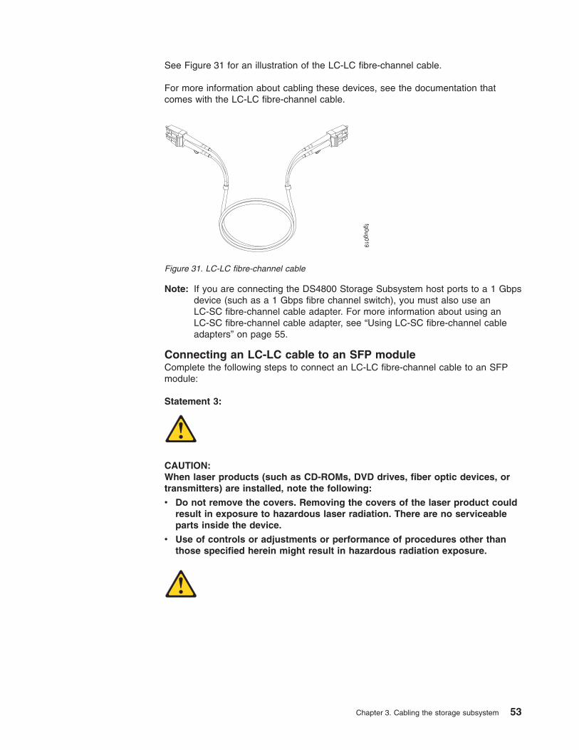
See Figure 31 for an illustration of the LC-LC fibre-channel cable.
For more information about cabling these devices, see the documentation that
comes with the LC-LC fibre-channel cable.
Note: If you are connecting the DS4800 Storage Subsystem host ports to a 1 Gbps
device (such as a 1 Gbps fibre channel switch), you must also use an
LC-SC fibre-channel cable adapter. For more information about using an
LC-SC fibre-channel cable adapter, see “Using LC-SC fibre-channel cable
adapters” on page 55.
Connecting an LC-LC cable to an SFP module
Complete the following steps to connect an LC-LC fibre-channel cable to an SFP
module:
Statement 3:
CAUTION:
When laser products (such as CD-ROMs, DVD drives, fiber optic devices, or
transmitters) are installed, note the following:
v Do not remove the covers. Removing the covers of the laser product could
result in exposure to hazardous laser radiation. There are no serviceable
parts inside the device.
v Use of controls or adjustments or performance of procedures other than
those specified herein might result in hazardous radiation exposure.
fg0ug019
Figure 31. LC-LC fibre-channel cable
Chapter 3. Cabling the storage subsystem 53

DANGER
Some laser products contain an embedded Class 3A or Class 3B laser
diode. Note the following.
Laser radiation when open. Do not stare into the beam, do not view directly
with optical instruments, and avoid direct exposure to the beam.
1. Read the information in “Handling fiber-optic cables” on page 48.
2. If necessary, remove the protective cap from the SFP module, as shown in
Figure 32. Save the protective cap for future use.
3. Remove the two protective caps from one end of the LC-LC cable, as shown in
Figure 32. Save the protective caps for future use.
4. Carefully insert this end of the LC-LC cable into an SFP module that is installed
in the DS4800. The cable connector is keyed to ensure it is inserted into the
SFP module correctly. Holding the connector, push in the cable until it clicks into
place, as shown in Figure 33.
5. Remove the two protective caps from the other end of the LC-LC cable. Save
the protective caps for future use.
6. Connect this end of the LC-LC cable to the SFP module that is installed in one
of the following devices.
Protective cap
Fiber-opticcable
F10ug011
Figure 32. Removing fiber-optic cable protective caps
F10ug016
Figure 33. Inserting an LC-LC fibre-channel cable into an SFP module
54 IBM System Storage DS4800 Storage Subsystem: Installation, User’s, and Maintenance Guide

v DS4000 storage expansion enclosure
v Fibre channel switch
v Host bus adapter
Removing an LC-LC fibre-channel cable
Attention: To avoid damaging the LC-LC cable or SFP module, make sure that
you observe the following precautions.
v Press and hold the lever to release the latches before you remove the cable from
the SFP module.
v Ensure that the levers are in the released position when you remove the cable.
v Do not grasp the SFP module plastic tab when you remove the cable.
Complete the following steps to remove an LC-LC fibre-channel cable:
1. On the end of the LC-LC cable that connects into the SFP module or host bus
adapter, press down and hold the lever to release the latches, as shown in
Figure 34.
2. Carefully pull on the connector to remove the cable from the SFP module, as
shown in Figure 35.
3. Replace the protective caps on the cable ends.
4. Replace the protective cap on the SFP module.
Using LC-SC fibre-channel cable adapters
The LC-SC fibre-channel cable adapter is a fiber-optic cable that is used to connect
an LC connector into one of the following devices that require SC connectors:
v 1 Gbps fibre channel switch
Lever
Latches f10ug018
Figure 34. LC-LC fibre-channel cable lever and latches
f10ug017
Figure 35. Removing the LC-LC fibre-channel cable
Chapter 3. Cabling the storage subsystem 55

v Fibre channel host bus adapter
Attention: The DS4800 does not support the attachment of storage expansion
enclosures that operate at 1 Gbps, such as the EXP500.
For more information about connecting to these devices, see the documentation
that comes with the LC-SC fibre-channel cable adapter.
The following sections provide the procedures for properly connecting and removing
an LC-SC fibre-channel cable.
Connecting an LC-SC cable adapter to a device
Complete the following steps to connect an LC-SC fibre-channel cable adapter to a
device:
Statement 3:
CAUTION:
When laser products (such as CD-ROMs, DVD drives, fiber optic devices, or
transmitters) are installed, note the following:
v Do not remove the covers. Removing the covers of the laser product could
result in exposure to hazardous laser radiation. There are no serviceable
parts inside the device.
v Use of controls or adjustments or performance of procedures other than
those specified herein might result in hazardous radiation exposure.
LC connector
SC connector
f10ug012
Figure 36. LC-SC fibre-channel cable adapter
56 IBM System Storage DS4800 Storage Subsystem: Installation, User’s, and Maintenance Guide

DANGER
Some laser products contain an embedded Class 3A or Class 3B laser
diode. Note the following.
Laser radiation when open. Do not stare into the beam, do not view directly
with optical instruments, and avoid direct exposure to the beam.
1. Read the information in “Handling fiber-optic cables” on page 48.
2. Connect one end of an LC-LC cable to an SFP module in the DS4800. For
instructions, see “Using LC-LC fibre-channel cables” on page 52.
3. Remove the two protective caps from the LC connector end of the LC-SC cable
adapter as shown in Figure 37. Save the protective caps for future use.
4. Carefully insert the other end of the LC-LC cable into the LC connector end of
the LC-SC cable adapter as shown in Figure 38. Push in the connector until it
clicks into place.
5. If you are connecting the DS4800 to a 1 Gbps fibre channel switch or fibre
channel host bus adapter, connect the SC connector end of the LC-SC cable
adapter to a Gigabit Interface Converter (GBIC) that is installed in the 1 Gbps
fibre channel switch or fibre channel host bus adapter. For more information
about connecting to these devices, see the documentation that comes with the
device.
f10ug013
Figure 37. Removing the LC-SC cable adapter protective caps
f10ug020
Figure 38. Connecting an LC-LC cable into the LC-SC cable adapter
Chapter 3. Cabling the storage subsystem 57

Removing an LC-LC cable from an LC-SC cable adapter
Complete the following steps to remove an LC-LC cable from an LC-SC cable
adapter:
Attention: To avoid damaging the LC-LC cable, make sure you press and hold
the lever to release the latches before you remove the cable from an LC-SC cable
adapter. Ensure that both levers are in the released position when removing the
cable. When removing the cable from the SFP module, make sure you do not grasp
the SFP module plastic tab.
1. On the end of the cable that connects into the LC connector end of the LC-SC
cable adapter, press down and hold the lever to release the latches. Figure 39
shows the location of the lever and latches.
2. Carefully pull on the connector to remove it. Make sure you grasp the connector
and not the cable when removing the LC-LC cable from the LC-SC cable
adapter as shown in Figure 40.
3. Replace the protective caps on the cable ends.
Lever
Latches f10ug018
Figure 39. LC-LC fibre-channel cable lever and latches
f10ug015
Figure 40. Removing the LC-LC fibre-channel cable from an LC-SC fibre-channel cable
adapter
58 IBM System Storage DS4800 Storage Subsystem: Installation, User’s, and Maintenance Guide

Connecting storage expansion enclosures to the DS4800
Attention
Before you power on the DS4800 Storage Subsystem, the DS4800 must be
cabled to at least one storage expansion enclosure populated with at least two
drives. If at least two drives are not installed in each attached storage
expansion enclosure when you power on the DS4800, your standard storage
partition key will be lost and will need to be regenerated using instructions on
the IBM DS4000 Solutions and Premium Features Web site:
https://www-912.ibm.com/PremiumFeatures/
Additionally, if at least two drives are not installed in each attached storage
expansion enclosure, the resulting insufficient load to the storage expansion
enclosure power supply CRUs might cause the drive expansion enclosure
power supply CRUs to intermittently appear as failed and then reappear in an
optimal state, falsely indicating that the power supply CRUs are bad.
In the initial installation of the DS4800, you can add only new storage expansion
enclosures to the DS4800 Storage Subsystem. This means that there must be no
existing configuration information on the storage expansion enclosures that you
want to install.
If the storage expansion enclosures that you want to install currently contain logical
drives or configured hot spares, and you want them to be part of the DS4800
Storage Subsystem configuration, refer to the IBM System Storage DS4000 Hard
Drive and Storage Expansion Enclosure Installation and Migration Guide. Improper
drive migration might cause loss of configuration and other storage subsystem
problems. Contact your IBM support representative for additional information.
Redundant drive channel pair
For the DS4800, each drive channel (see the Glossary definitions for ″drive
channels″ and ″drive loops″) is associated with two ports, and there are two drive
channels and four associated ports per controller. The total number of drives per
drive channel is 112. One channel from each controller combines to form a pair of
redundant drive channels. See Table 16 on page 68 for channel and port labeling
conventions.
In Figure 41 on page 61 and Figure 42 on page 62, drive channel 1 of controller A
and drive channel 3 of controller B combine to form a DS4800 Storage Subsystem
drive channel pair. If any component of drive channel 1 fails, the RAID controllers
can still access the storage expansion enclosures in drive channel 1 through drive
channel 3. Similarly, drive channel 2 of controller A and drive channel 4 of controller
B combine to form the second of the two DS4800 Storage Subsystem drive channel
pairs. If any component of drive channel 2 fails, the RAID controllers can still
access the storage expansion enclosures in drive channel 2 through drive channel
4.
Figure 41 on page 61 shows the storage expansion enclosures in each drive
channel pairs connected to only one drive port in the two-ported drive channel. For
example, in drive channel pair 1, only port 4 of channel 1 and port 1 of channel 3
are used. Figure 42 on page 62 shows that half of the storage expansion
enclosures in each drive channel pair are connected to the first port of the
Chapter 3. Cabling the storage subsystem 59

dual-ported drive channel. The other half of the enclosures are connected to the
second port of the dual-ported drive channel. For example, in drive channel/loop
pair 1, both ports 4 and 3 of channel 1 and port 1 and 2 of channel 3 are used.
Note: In the following drive cabling figures, the DS4800 graphics are simplified to
show only the drive ports of each controller.
60 IBM System Storage DS4800 Storage Subsystem: Installation, User’s, and Maintenance Guide
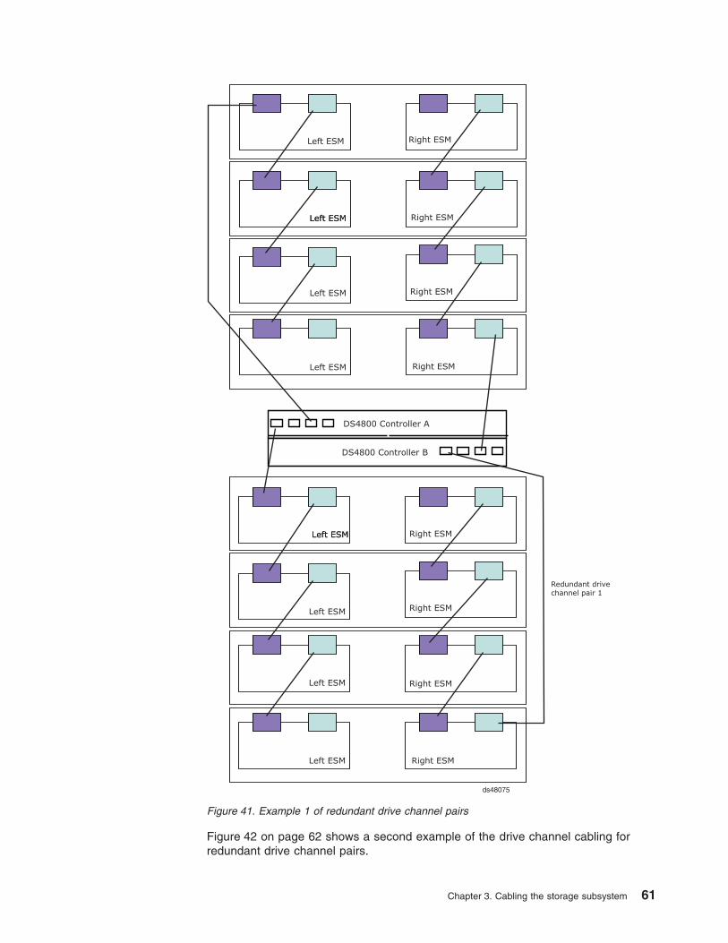
Figure 42 on page 62 shows a second example of the drive channel cabling for
redundant drive channel pairs.
Figure 41. Example 1 of redundant drive channel pairs
Chapter 3. Cabling the storage subsystem 61

Overview of steps to connect storage expansion enclosure to a
storage subsystem
To connect storage expansion enclosures to the storage subsystem, perform the
following steps:
Note: The following procedures are for cold-case procedures (in which the DS4800
is powered down when storage expansion enclosures are connected, as in
the case of initial installation). For hot-case procedures (in which the DS4800
is powered on when storage expansion enclosures are connected), refer to
the IBM System Storage DS4000 Hard Drive and Storage Expansion
Enclosure Installation and Migration Guide.
1. Follow the instructions in the Installation, User’s, and Maintenance Guide for
your DS4000 storage expansion enclosure, for setting up and mounting the
storage expansion enclosures.
2. Select a cabling topology appropriate for the number of storage expansion
enclosures you will connect to the DS4800. (You must connect at least one
storage expansion enclosure, populated with at least two drives, before you
power on the DS4800.)
“DS4800 Storage Subsystem drive cabling topologies” on page 69 describes the
recommended schemes for cabling different numbers of storage expansion
enclosures to the DS4800 and to each other (that is, if you are connecting more
than one storage expansion enclosure).
Figure 42. Example 2 of redundant drive channel pairs
62 IBM System Storage DS4800 Storage Subsystem: Installation, User’s, and Maintenance Guide

After you select the cabling topology for your configuration, continue with step 3,
following the cabling diagram for your chosen topology.
3. The following steps describe the cabling sequence for connecting at least two
storage expansion enclosures to a DS4800 using the preferred topologies
identified in “DS4800 Storage Subsystem drive cabling topologies” on page 69.
Note: If you are not using the preferred cabling topology, or if you are only
connecting one storage expansion enclosure to the DS4800, your cabling
sequence will differ from the following steps.
For either EXP100 or EXP710 storage expansion enclosure connections:
Perform the following steps to cable either the EXP710 or EXP100 storage
expansion enclosures to each other and to the DS4800.
Note: If you are intermixing different storage expansion enclosures such as
EXP100s, EXP710s, and EXP810s in a DS4800 configuration, refer to
the intermixing cabling diagrams provided in “DS4800 Storage
Subsystem drive cabling topologies” on page 69.
You can match the connections describing these steps with the cabling diagram
(provided in “DS4800 Storage Subsystem drive cabling topologies” on page 69)
that most closely matches your configuration. Figure 43 shows the name of the
ESM ports in the EXP710 /EXP100 storage expansion enclosures.
a. Starting on the DS4800 controller, connect drive port 4 (drive channel 1) of
controller A to the In port on the left ESM board of the first storage
expansion enclosure in the group. (See callout 1 in Figure 44 on page 64.)
b. From the first storage expansion enclosure that will be cabled together
behind a drive port of a drive channel, connect the Out port on the left ESM
board to the In port on the left ESM board of the second (next) enclosure.
(See callout 2 in Figure 44 on page 64.)
c. From the first storage expansion enclosure, connect the Out port on the right
ESM board to the In port on the right ESM board of the second (next)
enclosure. (See callout 6 in Figure 44 on page 64.)
d. If you are cabling more storage expansion enclosures to this group, repeat
the In port to Out port connections until you reach the last storage
expansion enclosure. (See callouts 3 and 4 for the left ESM connections
and callouts 7 and 8 for the right ESM connections in Figure 44 on page
64.)
Figure 43. EXP710 /EXP100 port labels
Chapter 3. Cabling the storage subsystem 63

e. On the last storage expansion enclosure in the group, connect the Out port
on the right ESM board to drive port 1 (drive channel 3) of controller B of
the DS4800. (See callout 5 in Figure 44.)
You have now completed the redundant fibre channel cabling of the first group
of storage expansion enclosures to the DS4800, using the first ports of the
dual-ported drive channels 1 and 3.
For EXP810 storage expansion enclosure connections:
Perform the following steps to cable EXP810 storage expansion enclosures to
each other and to the DS4800. You can match the connections described in
these steps with the cabling diagram (provided in “DS4800 Storage Subsystem
Figure 44. Connecting EXP710 or EXP100 enclosures to DS4800
64 IBM System Storage DS4800 Storage Subsystem: Installation, User’s, and Maintenance Guide

drive cabling topologies” on page 69) that most closely matches your
configuration. Figure 45 shows the name of the ESM ports in the EXP810
storage expansion enclosures.
a. Start with the first storage expansion enclosure from the group of EXP810
drive expansion enclosures that will be cabled together. Connect the 1A port
on the left ESM board to the 1B port on the left ESM board of the second
(next) enclosure. (See callout 2 in Figure 46 on page 66.)
b. On the first storage expansion enclosure from the group of drive expansion
enclosures that will be cabled together, connect the 1B port on the right
ESM board to the 1A port on the right ESM board of the second (next)
enclosure. (See callout 8 in Figure 46 on page 66.)
c. If you are cabling more storage expansion enclosures to this group, repeat
steps 3a and 3b for all enclosures except the final enclosure in the loop,
starting with the second enclosure. (See callouts 3 and 4 for the left ESM
connections and callouts 7 and 6 for the right ESM connections in Figure 46
on page 66.)
Figure 45. EXP810 port labels
Chapter 3. Cabling the storage subsystem 65

d. Connect drive port 4 (drive channel 1) of controller A to the to the 1B port on
the left ESM board of the first storage expansion enclosure in the group of
drive expansion enclosures. (See callout 1 in Figure 46.)
Figure 46. Connecting EXP810 enclosures to DS4800
66 IBM System Storage DS4800 Storage Subsystem: Installation, User’s, and Maintenance Guide

Important: Always connect the DS4800 controller port to the EXP810 ESM
port label 1B to ensure optimal drive channel performance. Do not connect
the DS4800 controller port to the EXP810 ESM port label 1A.
e. Connect drive port 1 (drive channel 3) of controller B to the port 1B on the
right ESM board of the last storage expansion enclosure in the group of
drive expansion enclosures. (See callout 5 in Figure 46 on page 66.)
Important: Always connect the DS4800 controller port to the EXP810 ESM
port label 1B to ensure optimal drive channel performance.
4. You can repeat steps 3a on page 63 to 3e on page 64 in order to connect other
groups of storage expansion enclosures to the DS4800, using the second ports
of the same dual-ported drive channel pair, and the first and second ports in the
other dual-ported drive channel pair, replacing the DS4800 drive ports
(mentioned in steps 3d on page 63 and 3e on page 64) with the appropriate
drive ports in the drive channels. The DS4800 currently supports a maximum of
112 drives in either eight 14-drive storage expansion enclosures or seven
16-drive storage expansion enclosures per drive channel in each controller. One
drive channel from each of controllers A and B must be connected to the same
set of storage expansion enclosures to provide drive channel redundancy. This
will result in the support of a maximum of 224 drives in 16 or 14 storage
expansion enclosures per DS4800, depending on storage expansion enclosure
type.
5. Set unique enclosure IDs for all storage expansion enclosures that are cabled to
the DS4800 for the EXP710 and EXP100 only. See “DS4000 storage expansion
enclosure ID settings” on page 86, and refer to your storage expansion
enclosure installation manual for details on setting the enclosure ID.
The DS4800 Storage Subsystem locates the drives in the storage expansion
enclosures after you power on the configuration. Always connect power to the
storage expansion enclosures first and then connect power to the DS4800. After
you have powered on the configuration, use the DS4000 Storage Manager client to
check the status of the new drives, correct any errors found, and configure the new
drives.
DS4800 drive cabling rules and recommendations
Refer to these general rules and recommendations when completing the cabling
steps described in this document.
1. Do not connect a combination of more than eight EXP710/EXP100 or seven
EXP810 storage expansion enclosures to the two ports of a dual-ported drive
channel. Failure to observe this limitation might result in loss of data
availability.
2. Do not connect more than four EXP810 storage expansion enclosures to each
port of the dual-ported drive channel. There are no restrictions to four or less
storage expansion enclosures connected per drive port for the EXP710 and
the EXP100 storage expansion enclosures; however, IBM recommends using
the same rule for the EXP710/EXP100 enclosures to maximize drive channel
performance.
Note: As long as there is one EXP810 enclosure behind a controller drive
port, the maximum number of enclosures that can be connected behind
that controller drive is four.
3. If there are four or more EXP710s to be connected to a channel, split them
evenly across the two channel ports associated with the channel. If there is an
odd number of EXP710s, then one channel port will have one more EXP710
connected to it than the other channel port.
Chapter 3. Cabling the storage subsystem 67
||||

4. If there are three or fewer EXP710s to be connected to a channel, then they
should all be daisy-chained together to one channel port on the channel. The
other channel port should be left unconnected.
5. If you are mixing EXP710s and EXP100s, all EXP710s must be grouped
together and all EXP100s must be grouped together.
6. It is recommended that you add storage expansion enclosures to the DS4800
drive ports in a round-robin fashion. For example, if you have four EXP810s to
be cabled to the DS4800, instead of cabling all four EXP810s to one drive port
of a drive channel, distribute the enclosures to all drive ports, which results in
one enclosure per drive port of a drive channel.
7. Do not connect more than the recommended maximum number of enclosures
per drive channel (eight for 14-drive and seven for 16-drive enclosures). When
mixing 14-drive and 16-drive enclosures, the maximum number of expansion
enclosures is seven per redundant drive channel pair.
8. DS4800 supports storage expansion enclosures operating at different fibre
channel speeds (for example, 2 Gbps or 4 Gbps) only when they are installed
in separate redundant drive channel pairs. DS4800 does not support a mix of
storage expansion enclosures operating at different fibre channel speeds in the
same redundant drive channel pair.
9. DS4800 supports a mix of EXP100, EXP710, and EXP810 storage expansion
enclosures in the same redundant drive channel pair. If possible, it is
recommended that you cable the storage expansion enclosures of the same
type together to ease maintenance and troubleshooting in the event of failures.
For specific cabling rules and restrictions when intermixing EXP100, EXP710,
and EXP810 storage expansion enclosures, see “One DS4800 to two or more
storage expansion enclosures in a mixed environment” on page 81.
10. The DS4000 controller drive port must always be connected to the EXP810
port labeled 1B. Because the left and right EXP810 ESMs (ESMs A and B) are
inserted in the ESM bays in different orientations, you must look for the port
labeled 1B before making the fibre channel connections.
11. Table 16 indicates a number of ways that four storage expansion enclosures
can be attached to the DS4800 controller drive ports. Case 7 is the
recommended way. Depending on your need and the type of storage
expansion enclosures that you used, you may also choose one of the other
ways described in the table. For example, in a given drive channel, you can
connect three storage expansion enclosures to the first port and five storage
expansion enclosures to the second port, or you can connect four storage
expansion enclosures to the first port and four storage expansion enclosures to
the second port. You cannot connect three storage expansion enclosures to
the first port and six storage expansion enclosures to the second port or one
storage expansion enclosure to the first port and eight storage expansion
enclosures to the second port; in these cases, the total number of storage
expansion enclosures connected to a single drive channel is greater than eight.
Table 16. Different ways to connect four storage expansion enclosures to the DS4800
Drive Channel 1
port 4
Drive Channel 1
port 3
Drive Channel 2
port 2
Drive Channel 2
port 1
Case 1 4 0 0 0
Case 2 3 1 0 0
Case 3 0 3 1 0
Case 4 2 2 0 0
Case 5 0 2 2 0
68 IBM System Storage DS4800 Storage Subsystem: Installation, User’s, and Maintenance Guide
|||
||
||||
|||||||

Table 16. Different ways to connect four storage expansion enclosures to the
DS4800 (continued)
Drive Channel 1
port 4
Drive Channel 1
port 3
Drive Channel 2
port 2
Drive Channel 2
port 1
Case 6 1 3 0 0
Case 7 1 1 1 1
DS4800 Storage Subsystem drive cabling topologies
The following sections provide preferred cabling topologies for cabling storage
expansion enclosures to the DS4800 Storage Subsystem. Each example provides
redundant paths to the drives. If one of these examples is suitable for your
hardware and application, complete the cabling connections as described in the
tables. If you have hardware to include in your topology other than what is shown in
these examples, use the examples as a starting point for creating your specific
topology.
Attention: The DS4800 supports the connection of a maximum of eight storage
expansion enclosures per redundant drive channel pair. The DS4800 supports two
redundant drive channel pairs.
If you are using fiber-optic cables, install SFP modules into the ports that will
receive the cables before installing the cables.
Figure 47 on page 70 shows the locations of controllers A and B, and the
single-ported host channels, Ethernet ports, and dual-ported drive channels at the
back of the DS4800 Storage Subsystem.
Chapter 3. Cabling the storage subsystem 69
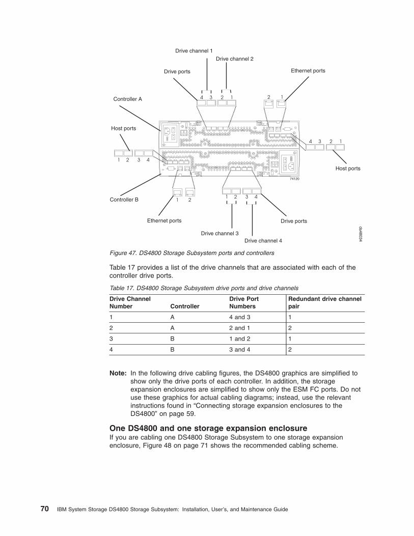
Table 17 provides a list of the drive channels that are associated with each of the
controller drive ports.
Table 17. DS4800 Storage Subsystem drive ports and drive channels
Drive Channel
Number Controller
Drive Port
Numbers
Redundant drive channel
pair
1 A 4 and 3 1
2 A 2 and 1 2
3 B 1 and 2 1
4 B 3 and 4 2
Note: In the following drive cabling figures, the DS4800 graphics are simplified to
show only the drive ports of each controller. In addition, the storage
expansion enclosures are simplified to show only the ESM FC ports. Do not
use these graphics for actual cabling diagrams; instead, use the relevant
instructions found in “Connecting storage expansion enclosures to the
DS4800” on page 59.
One DS4800 and one storage expansion enclosure
If you are cabling one DS4800 Storage Subsystem to one storage expansion
enclosure, Figure 48 on page 71 shows the recommended cabling scheme.
74120
1 1
1
1
1
2 2
2
2
2
3
3
3
4
1234
4
4
Controller A
Controller B
Host ports
Host ports
Drive ports
Drive ports Ethernet ports
Ethernet ports
Drive channel 1
Drive channel 2
Drive channel 3Drive channel 4
ds48034
Figure 47. DS4800 Storage Subsystem ports and controllers
70 IBM System Storage DS4800 Storage Subsystem: Installation, User’s, and Maintenance Guide

Table 18. Description of Figure 48
Number Description
�1� Drive channel 1
�3� Drive channel 3
�2� Enclosure 1
1. To create drive channel 1, connect drive port 4 of controller A to enclosure 1
(�2�).
2. To create drive channel 3, connect drive port 1 of controller B to enclosure 1
(�2�).
One DS4800 and two storage expansion enclosures
If you are cabling one DS4800 Storage Subsystem to two storage expansion
enclosures, Figure 49 on page 72 shows the recommended cabling schemes.
As Figure 49 on page 72 and Figure 50 on page 73 show, when you connect
additional storage expansion enclosures, you can connect them either by using the
additional port of the drive channel or by continuing the connection from the existing
redundant drive channel pair. View 1 is the recommended cabling topology; View 2
is a possible cabling topology, however, it is not recommended.
Figure 48. One DS4800 and one storage expansion enclosure — Recommended cabling
Chapter 3. Cabling the storage subsystem 71

Table 19. Description of Figure 49
Number Description
�1� Drive channel 1
�3� Drive channel 3
�2� Enclosure 1
�4� Enclosure 2
1. To create drive channel 1, connect drive port 4 of controller A to enclosure 1
(�2�) and drive port 3 to enclosure 2 (�4�).
2. To create drive channel 3, connect drive port 1 of controller B to enclosure 1
(�2�) and drive port 2 to enclosure 2 (�4�).
Figure 49. View 1: One DS4800 and two storage expansion enclosures
cabling—recommended
72 IBM System Storage DS4800 Storage Subsystem: Installation, User’s, and Maintenance Guide

One DS4800 and four storage expansion enclosures
If you are cabling one DS4800 Storage Subsystem to four storage expansion
enclosures, Figure 51 on page 74 shows the recommended cabling scheme.
Figure 50. View 2: One DS4800 and two storage expansion enclosures cabling — not
recommended
Chapter 3. Cabling the storage subsystem 73

Table 20. Description of Figure 51
Number Description
�1� Drive channel 1
�2� Drive channel 2
�3� Drive channel 3
�4� Drive channel 4
�5� Enclosure 1
�6� Enclosure 2
�7� Enclosure 3
�8� Enclosure 4
1. To create drive channel 1, connect drive port 4 of controller A to enclosure 1
(�5�) and drive port 3 to enclosure 2 (�6�).
2. To create drive channel 3, connect drive port 1 of controller B to enclosure 1
(�5�) and drive port 2 to enclosure 2 (�6�).
3. To create drive channel 2, connect drive port 2 of controller A to enclosure 3
(�7�) and drive port 1 to enclosure 4 (�8�).
4. To create drive channel 4, connect drive port 3 of controller B to enclosure 3
(�7�) and drive port 4 to enclosure 4 (�8�).
Figure 51. One DS4800 and four storage expansion enclosures—recommended cabling
74 IBM System Storage DS4800 Storage Subsystem: Installation, User’s, and Maintenance Guide

One DS4800 and eight storage expansion enclosures
If you are cabling one DS4800 Storage Subsystem to eight storage expansion
enclosures of the same type, it is recommended that you evenly divide the
enclosures between the ports of two redundant dual-ported drive channel pairs,
instead of connecting in groups of up to four storage expansion enclosures behind
certain ports of the two redundant drive channel pairs. Figure 52 illustrates the
cabling topology for one DS4800 Storage Subsystem attached to eight storage
expansion enclosures.
Table 21. Description of Figure 52
Number Description
�1� Drive channel 1
Figure 52. One DS4800 and eight storage expansion enclosures—recommended cabling
Chapter 3. Cabling the storage subsystem 75
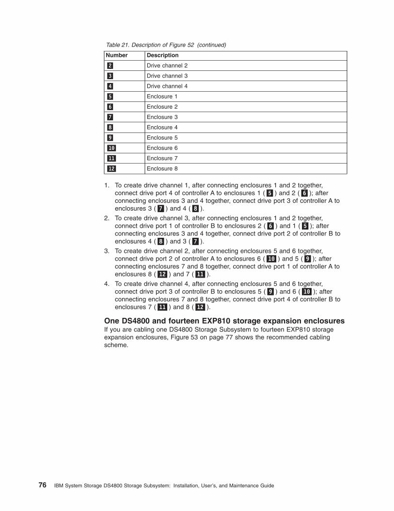
Table 21. Description of Figure 52 (continued)
Number Description
�2� Drive channel 2
�3� Drive channel 3
�4� Drive channel 4
�5� Enclosure 1
�6� Enclosure 2
�7� Enclosure 3
�8� Enclosure 4
�9� Enclosure 5
�10� Enclosure 6
�11� Enclosure 7
�12� Enclosure 8
1. To create drive channel 1, after connecting enclosures 1 and 2 together,
connect drive port 4 of controller A to enclosures 1 (�5�) and 2 (�6�); after
connecting enclosures 3 and 4 together, connect drive port 3 of controller A to
enclosures 3 (�7�) and 4 (�8�).
2. To create drive channel 3, after connecting enclosures 1 and 2 together,
connect drive port 1 of controller B to enclosures 2 (�6�) and 1 (�5�); after
connecting enclosures 3 and 4 together, connect drive port 2 of controller B to
enclosures 4 (�8�) and 3 (�7�).
3. To create drive channel 2, after connecting enclosures 5 and 6 together,
connect drive port 2 of controller A to enclosures 6 (�10�) and 5 (�9�); after
connecting enclosures 7 and 8 together, connect drive port 1 of controller A to
enclosures 8 (�12�) and 7 (�11�).
4. To create drive channel 4, after connecting enclosures 5 and 6 together,
connect drive port 3 of controller B to enclosures 5 (�9�) and 6 (�10�); after
connecting enclosures 7 and 8 together, connect drive port 4 of controller B to
enclosures 7 (�11�) and 8 (�12�).
One DS4800 and fourteen EXP810 storage expansion enclosures
If you are cabling one DS4800 Storage Subsystem to fourteen EXP810 storage
expansion enclosures, Figure 53 on page 77 shows the recommended cabling
scheme.
76 IBM System Storage DS4800 Storage Subsystem: Installation, User’s, and Maintenance Guide

Table 22. Description of Figure 53
Number Description
�4A� Connection from drive port 4 controller A
�1B� Connection from drive port 1 controller B
�3A� Connection from drive port 3 controller A
�2B� Connection from drive port 2 controller B
�2A� Connection from drive port 2 controller A
�3B� Connection from drive port 3 controller B
�1A� Connection from drive port 1 controller A
�4B� Connection from drive port 4 controller B
�21� Drive channel 1
�23� Drive channel 3
�22� Drive channel 2
�24� Drive channel 4
�5� EXP810 enclosure 1
�6� EXP810 enclosure 2
�7� EXP810 enclosure 3
�8� EXP810 enclosure 4
�9� EXP810 enclosure 5
�10� EXP810 enclosure 6
�11� EXP810 enclosure 7
�12� EXP810 enclosure 8
�13� EXP810 enclosure 9
�14� EXP810 enclosure 10
�15� EXP810 enclosure 11
�16� EXP810 enclosure 12
�17� EXP810 enclosure 13
Figure 53. One DS4800 and fourteen EXP810 storage expansion enclosures—recommended cabling
Chapter 3. Cabling the storage subsystem 77

Table 22. Description of Figure 53 (continued)
Number Description
�18� EXP810 enclosure 14
1. Make all connections from the left ESMs to the right ESMs in the expansion
enclosures, as indicated by �21�, �23�, �22�, and �24�.
2. To create drive channel 1, after connecting enclosures 1, 2, 3, and 4 together
(�21�), connect drive port 4 of controller A (�4A�) to EXP810 enclosures 1 (�5�),
2 (�6�), 3 (�7�), and 4 (�8�); then, connect drive port 1 of controller B (�1B�) to
enclosures 4 (�8�), 3 (�7�), 2 (�6�), and 1 (�5�).
3. To create drive channel 3, after connecting enclosures 5, 6, and 7 together
(�23�), connect drive port 3 of controller A (�3A�) to enclosures 5 (�9�), 6 (�10�),
and 7 (�11�); then, connect port 2 of controller B (�2B�) to enclosures 7 (�11�),
6 (�10�), and 5 (�9�).
4. To create drive channel 2, after connecting enclosures 8, 9, 10, and 11 together
(�22�), connect drive port 2 of controller A (�2A�) to enclosures 8 (�12�), 9
(�13�), 10 (�14�), and 11 (�15�); then, connect drive port 3 of controller B (�3B�)
to enclosures 11 (�15�), 10 (�14�), 9 (�13�), and 8 (�12�).
5. To create drive channel 4, after connecting enclosures 12, 13, and 14 together
(�24�), connect drive port 1 of controller A (�1A�) to enclosures 12 (�16�), 13
(�17�), and 14 (�18�); then, connect drive port 4 of controller B (�4B�) to
enclosures 14 (�18�), 13 (�17�), and 12 (�16�).
One DS4800 and sixteen EXP710 storage expansion enclosures
If you are cabling one DS4800 Storage Subsystem to sixteen EXP710 storage
expansion enclosures, Figure 54 shows the recommended cabling scheme.
Table 23. Description of Figure 54
Number Description
�4A� Connection from drive port 4 controller A
�1B� Connection from drive port 1 controller B
�3A� Connection from drive port 3 controller A
Figure 54. One DS4800 and sixteen EXP710 storage expansion enclosure—recommended cabling
78 IBM System Storage DS4800 Storage Subsystem: Installation, User’s, and Maintenance Guide

Table 23. Description of Figure 54 (continued)
Number Description
�2B� Connection from drive port 2 controller B
�2A� Connection from drive port 2 controller A
�3B� Connection from drive port 3 controller B
�1A� Connection from drive port 1 controller A
�4B� Connection from drive port 4 controller B
�1� Drive channel 1
�2� Drive channel 2
�3� Drive channel 3
�4� Drive channel 4
�5� EXP710 enclosure 1
�6� EXP710 enclosure 2
�7� EXP710 enclosure 3
�8� EXP710 enclosure 4
�9� EXP710 enclosure 5
�10� EXP710 enclosure 6
�11� EXP710 enclosure 7
�12� EXP710 enclosure 8
�13� EXP710 enclosure 9
�14� EXP710 enclosure 10
�15� EXP710 enclosure 11
�16� EXP710 enclosure 12
�17� EXP710 enclosure 13
�18� EXP710 enclosure 14
�19� EXP710 enclosure 15
�20� EXP710 enclosure 16
1. Make all connections from the left ESMs to the right ESMs in the expansion
enclosures, as indicated by �21�, �23�, �22�, and �24�.
2. To create drive channel 1, after connecting enclosures 1, 2, 3, and 4 together
(�21�), connect drive port 4 of controller A (�4A�) to EXP710 enclosures 1 (�5�),
2 (�6�), 3 (�7�), and 4 (�8�); then, connect drive port 1 of controller B (�1B�) to
enclosures 4 (�8�), 3 (�7�), 2 (�6�), and 1 (�5�).
3. To create drive channel 3, after connecting enclosures 5, 6, 7, and 8 together
(�23�), connect drive port 3 of controller A (�3A�) to enclosures 5 (�9�), 6 (�10�),
7 (�11�), and 8 (�12�); then, connect port 2 of controller B (�2B�) to enclosures
8 (�12�), 7 (�11�), 6 (�10�), and 5 (�9�).
4. To create drive channel 2, after connecting enclosures 9, 10, 11, and 12
together (�22�), connect drive port 2 of controller A (�2A�) to enclosures 9
(�13�), 10 (�14�), 11 (�15�), and 12 (�16�); then, connect drive port 3 of
controller B (�3B�) to enclosures 12 (�16�), 11 (�15�), 10 (�14�), and 9 (�13�).
5. To create drive channel 4, after connecting enclosures 13 (�17�), 14 (�18�), 15
(�19�), and 16 (�20�) together (�24�), connect drive port 1 of controller A (�1A�)
Chapter 3. Cabling the storage subsystem 79

to enclosures 13 (�17�), 14 (�18�), 15 (�19�), and 16 (�20�); then, connect drive
port 4 of controller B (�4B�) to enclosures 16 (�20�), 15 (�19�), 14 (�18�), and
13 (�17�).
One DS4800 to seven EXP810 and eight EXP710 storage
expansion enclosures
If you are cabling one DS4800 Storage Subsystem to seven EXP810 storage
expansion enclosures operating at 4 Gbps and eight EXP710 storage expansion
enclosures operating at 2 Gbps, Figure 55 shows the recommended cabling
scheme.
Table 24. Description of Figure 55
Number Description
�4A� Connection from drive port 4 controller A
�1B� Connection from drive port 1 controller B
�3A� Connection from drive port 3 controller A
�2B� Connection from drive port 2 controller B
�2A� Connection from drive port 2 controller A
�3B� Connection from drive port 3 controller B
�1A� Connection from drive port 1 controller A
�4B� Connection from drive port 4 controller B
�1� Drive channel 1
�2� Drive channel 2
�3� Drive channel 3
�4� Drive channel 4
�5� EXP810 enclosure 1
�6� EXP810 enclosure 2
�7� EXP810 enclosure 3
�8� EXP810 enclosure 4
�9� EXP810 enclosure 5
Figure 55. One DS4800 to seven EXP810 and eight EXP710 storage expansion enclosures—recommended cabling
80 IBM System Storage DS4800 Storage Subsystem: Installation, User’s, and Maintenance Guide

Table 24. Description of Figure 55 (continued)
Number Description
�10� EXP810 enclosure 6
�11� EXP810 enclosure 7
�12� EXP710 enclosure 1
�13� EXP710 enclosure 2
�14� EXP710 enclosure 3
�15� EXP710 enclosure 4
�16� EXP710 enclosure 5
�17� EXP710 enclosure 6
�18� EXP710 enclosure 7
�19� EXP710 enclosure 8
1. Make all connections from the left ESMs to the right ESMs in the expansion
enclosures, as indicated by �21�, �23�, �22�, and �24�.
2. To create drive channel 1, after connecting enclosures 1, 2, 3, and 4 together
(�21�), connect drive port 4 of controller A (�4A�) to EXP810 enclosures 1 (�5�),
2 (�6�), 3 (�7�), and 4 (�8�); then, connect drive port 1 of controller B (�1B�) to
enclosures 4 (�8�), 3 (�7�), 2 (�6�), and 1 (�5�).
3. To create drive channel 3, after connecting enclosures 5, 6, and 7 together
(�23�), connect drive port 3 of controller A (�3A�) to EXP810 enclosures 5 (�9�),
6 (�10�), and 7 (�11�); then, connect port 2 of controller B (�2B�) to enclosures
7 (�11�), 6 (�10�), and 5 (�9�).
4. To create drive channel 2, after connecting EXP710 enclosures 8, 9, 10, and 11
together (�22�), connect drive port 2 of controller A (�2A�) to enclosures 8
(�12�), 9 (�13�), 10 (�14�), and 11 (�15�); then, connect drive port 3 of controller
B (�3B�) to enclosures 11 (�15�), 10 (�14�), 9 (�13�), and 8 (�12�).
5. To create drive channel 4, after connecting EXP710 enclosures 12 (�16�), 13
(�17�), 14 (�18�), and 15 (�19�) together (�24�), connect drive port 1 of
controller A (�1A�) to enclosures 12 (�16�), 13 (�17�), 14 (�18�), and 15 (�19�);
then, connect drive port 4 of controller B (�4B�) to enclosures 15 (�19�), 14
(�18�), 13 (�17�), and 12 (�16�).
One DS4800 to two or more storage expansion enclosures in a
mixed environment
When intermixing EXP100s, EXP710s, and EXP810s in a DS4800 storage
subsystem configuration, if it is not possible to cable each group of enclosures by
model type (EXP100s, EXP710s, and EXP810s) in a separate redundant drive loop
pair or behind each port of the dual-ported redundant drive channel pair, group
them so that EXP810s are between EXP100s and EXP710s.
In addition, when an EXP100 is the first storage expansion enclosure cabled
directly to the storage subsystem's controller drive port, follow these rules:
v Cable from the storage subsystem controller drive port to the OUT port on the
left ESM (ESM A) of the EXP100.
Note: This is a change from previous cabling recommendations where you
cabled from the controller drive port to the IN port on the left ESM (ESM
A) of the EXP100.
v If an EXP100 follows the initial EXP100, cable from the IN port on the left ESM
(ESM A) of the first EXP100 to the OUT port on the left ESM of the next
Chapter 3. Cabling the storage subsystem 81
|||||||
||
||
|||
||

EXP100. Continue this cabling pattern until you encounter an EXP710 or
EXP810, then cable from the IN port on the left ESM (ESM A) of the EXP100 to
the IN port of the EXP710 or EXP810.
v If an EXP710 or EXP810 follows the initial EXP100, cable from the IN port on the
left ESM (ESM A) of the EXP100 to the IN port of the EXP710 or EXP810. To
cable to the next storage expansion enclosure in the chain, cable from the OUT
port of the left ESM of the EXP710 or EXP810 to the IN port of the next storage
expansion enclosure.
v Continue the left ESM (ESM A) cabling pattern by cabling from the OUT port to
the IN port on subsequent storage expansion enclosures until you complete the
chain.
Figure 56 shows an acceptable EXP710, EXP810 and EXP100 intermix
configuration in a DS4800 environment. The cabling is acceptable because it
follows the cabling recommendations.
Table 25. Description of Figure 56
Number Description
1 DS4800 Storage Subsystem
2 EXP100
3 EXP810
4 IN port
5 OUT port
6 Port 1B
ESM B
ESM A
ESM BESM A
ESM BESM A
ESM BESM A
ESM B
ESM A
ESM BESM A
Out
ESM B
ESM A
ESM B
ESM A
1 1
22
2
3
3
4 5 4 5
4 45 5
6 7
67
6 7
7 6
6 7
7 6
6 7
7 6
4 45 5
4 45 5
exp100810a
Figure 56. Acceptable EXP710, EXP810 and EXP100 intermix configuration in a DS4800
environment
82 IBM System Storage DS4800 Storage Subsystem: Installation, User’s, and Maintenance Guide
|
|||
|||
|||||
|||
||||
||
||
||
||
||
||
||
||

Table 25. Description of Figure 56 on page 82 (continued)
Number Description
7 Port 1A
Figure 57 shows an unacceptable EXP710, EXP810, and EXP100 intermix
configuration in a DS4800 environment. The cabling is unacceptable because
storage subsystem controller is cabled to the IN port on the left ESM of the first
EXP100.
Table 26. Description of Figure 57
Number Description
1 DS4800 Storage Subsystem
2 EXP100
ESM B
ESM A
ESM BESM A
ESM B
ESM A
ESM BESM A
1
22
3
4 5 4 5
4 45 5
6 7
67
6 7
7 6 exp100810u
Figure 57. Unacceptable EXP710, EXP810 and EXP100 intermix configuration in a DS4800
environment
Chapter 3. Cabling the storage subsystem 83
|
|||
|
||
|||
|||||
||
||
||
||

Table 26. Description of Figure 57 on page 83 (continued)
Number Description
3 EXP810
4 IN port
5 OUT port
6 Port 1B
7 Port 1A
Figure 58 shows cabling variations when intermixing EXP100, EXP710, and
EXP810 storage expansion enclosures behind a DS4800 Storage Subsystem.
Table 27. Description of Figure 58
Number Description
1 DS4800 Storage Subsystem
2 EXP100
3 EXP810
4 EXP710
Cabling the storage expansion enclosures to a DS4800 storage
subsystem
Complete the following steps to cable the storage expansion enclosures to a
DS4800 Storage Subsystem:
1. Install an SFP module in the drive mini hub port on the back of the DS4800
Storage Subsystem, as shown in Figure 59 on page 85.
2. Connect an LC-LC fiber-optic cable into the SFP module, as shown in Figure 60
on page 85.
1
2
2
2 2
3
3
4
4
4
ds48086
2
Figure 58. Cabling variations when intermixing EXP100, EXP710, and EXP810 storage expansion enclosures behind a
DS4800 Storage Subsystem
84 IBM System Storage DS4800 Storage Subsystem: Installation, User’s, and Maintenance Guide
|
|||
|
||
||
||
||
||
|||
|||
||
||
||
||
||
|||
|

Install an SFP module in the SFP port on the back of the storage expansion
enclosures; then, connect the other end of the LC-LC cable into the SFP module,
as shown in Figure 60.
For important information about connection rules and recommendations, see 4 on
page 67.
Storage expansion enclosure settings
This section provides information about storage expansion enclosure settings. For
additional detail, refer to the Installation, User’s, and Maintenance Guide for your
storage expansion enclosure.
ds48031
Figure 59. Installing an SFP module and LC-LC cable in a DS4800
Fiber-opticcable
SFPmodule
exp81012
Figure 60. Installing an SFP module and connecting an LC-LC cable to the storage
expansion enclosures
Chapter 3. Cabling the storage subsystem 85
Fibre channel loop and ID settings
When you install a hard disk drive in the storage expansion enclosure, the drive
tray plugs into a printed circuit board called the midplane. The midplane sets the
fibre channel loop ID automatically, based on the enclosure ID switch setting and
the physical location (bay) of the hard disk drive.
DS4000 storage expansion enclosure ID settings
DS4000 storage expansion enclosures have an enclosure ID switch that is used to
identify the DS4000 storage expansion enclosure on a fibre channel loop. The
enclosure ID switch is located on the back of the unit.
Use the small buttons above and below each enclosure ID digit to change the
enclosure ID setting. Press the button located above the digit to lower the digit by
one. Press the button located below the digit to raise the digit by one.
Note: Some DS4000 storage expansion enclosures ship with a panel installed over
the enclosure ID switch to prevent the enclosure ID from being changed
accidentally. If your DS4000 storage expansion enclosure has a protective
panel over the ID switch, use a pencil or a small screwdriver to change the
enclosure ID.
Each storage expansion enclosure in a DS4000 Storage Subsystem drive loop must
have a unique enclosure ID. DS4000 controllers use a combination of the enclosure
ID and the number of the physical slots that a hard drive occupies to create a
unique fibre channel loop address, or arbitrated loop physical address (AL_PA), for
each drive in a fibre channel drive loop. The enclosure ID consists of two digits, a
tens digit (x10) and a ones digit (x1). The enclosure IDs of the EXP710 and
EXP100 storage expansion enclosures must be manually set, whereas the
enclosure IDs of the EXP810s are automatically adjusted to be unique values by
the EXP810 ESM and the DS4800 controller firmware.
86 IBM System Storage DS4800 Storage Subsystem: Installation, User’s, and Maintenance Guide

Attention: When connecting storage expansion enclosures, it is recommended
that you use the tens digit (x10) enclosure ID setting to distinguish different
redundant loops and use the ones digit (x1) enclosure ID setting to distinguish
storage expansion enclosures IDs within a redundant loop. If you do not set the
single digit value of the enclosure IDs to be unique among storage expansion
enclosures (including the DS4000 storage subsystem with drives installed) in a
redundant drive channel/loop pair, then drive loop errors might be randomly posted
in the DS4000 subsystem Major Event Log (MEL) when you intermix different types
of storage expansion enclosures in a redundant drive loop pair (such as an EXP100
with an EXP810). For example, in a DS4800 configuration with 16 storage
expansion enclosures distributed equally behind the four controller drive ports, the
recommended enclosure ID settings for the enclosures are shown in Table 28.
Table 28. Recommended enclosure ID settings scheme
Enclosure ID
behind the first
controller drive
port
Enclosure ID
behind the
second
controller drive
port
Enclosure ID
behind the third
controller drive
port
Enclosure ID
behind the
fourth controller
drive port
Enclosure 1 00 04 10 14
Enclosure 2 01 05 11 15
Enclosure 3 02 06 12 16
Enclosure 4 03 07 13 17
The DS4800 normally ships with an enclosure ID outside the range of 00–77.
However, if your DS4800 enclosure ID was set to a value within the range of
00–77, it may be in conflict with the enclosure ID of one of the EXP100 or EXP710
drive expansion enclosures that you are trying to attach to the DS4800. If this is the
case, the amber ID Conflict LED on the storage expansion enclosure will light up
after you power on the storage subsystem.
Give each storage expansion enclosure in a redundant drive channel pair a unique
ones digit (x1) ID. This setting will enforce hard AL_PAs (unchangeable between
fibre channel Loop Initializations [LIPs]) for the drives and facilitate drive channel
problem troubleshooting in the event of an error. If the ones digits are not unique,
two or more devices will have the same hard AL_PA. In such a case, the DS4800
controller will use soft AL_PAs for the devices that have identical hard AL_PAs.
The problem with soft addressing is that addresses may change between LIPs. This
possibility increases the difficulty of troubleshooting drive channel problems, since
one cannot easily ascertain whether the same device with a different address or a
different device may be causing a problem.
Connecting hosts to the DS4800
The DS4800 supports redundant connections to up to four hosts. To ensure full
protection against the loss of any one fibre channel path from the host servers to
the DS4800 Storage Subsystem, always use redundant host connections by
connecting each host to the appropriate single-ported host channels on both RAID
controllers A and B.
To connect a host adapter to the DS4800 RAID controllers, perform the following
steps:
Chapter 3. Cabling the storage subsystem 87
||||||||||||
||
|
||||
|||||
||||
||||
|||||
|||||
|||||
||||||
||||||

1. Install SFP modules in host ports on RAID controllers A and B.
Note: The alignment of the single-ported host channels on controller A are
opposite those of controller B. Before inserting an SFP module into a
host port, verify that the SFP module is rotated correctly to match the
alignment of the host port on the RAID controller. Do not force-fit.
2. Connect the fibre channel cables from the SFP modules in the DS4800 RAID
controller host ports to either the SFP modules in the fibre channel switch or the
SFP modules of the host bus adapters. Figure 61 shows the location on the
RAID controllers where the host-system cables connect.
3. Repeat steps 1 and 2 for each additional redundant host connection. You can
create a maximum of four redundant host connections, as shown in Figure 62
on page 89.
Note: Figure 62 on page 89 shows that the DS4800 host ports are connected
to four sets of FC host bus adapters (HBAs). You can replace one or all
of these sets of FC HBAs with FC switches as required.
Host A: Host adapter2 (or from managedhub or switch)
Controller B
Controller AHost A: Host adapter1 (or from managedhub or switch)
ds48032
Figure 61. Location of host cables on RAID controllers
88 IBM System Storage DS4800 Storage Subsystem: Installation, User’s, and Maintenance Guide

For examples of redundant, partially redundant, and non-redundant host and drive
channel configurations, see “Fibre channel host loop configurations” on page 93.
Connecting secondary interface cables
This section is applicable to (direct) out-of-band management configurations only. If
your configuration uses host-agent (in-band) management, skip this section.
Use the Ethernet interface ports on the back of the storage subsystem to connect
the controllers for direct management of the storage subsystems (see “Direct
(out-of-band) management method” on page 91).
Important:
1. The serial interface ports are intended to be used by service technicians to
perform diagnostic operations on the storage subsystem. Incorrect use of the
serial port can result in loss of data access and, in some cases, in loss of data.
Do not make connections to the serial port unless you do so under the direct
supervision and guidance of IBM support personnel.
2. To minimize security risks, do not connect the DS4800 in a public LAN or public
subnet. Use a local private network for the DS4800 and the management
station Ethernet ports.
3. To ensure proper EMI shielding, always use quality braided and shielded serial
cables.
Connect a pair of Ethernet cables from the storage-management station to the
Ethernet ports for controller A (located on the top) and controller B (located on the
bottom) on the back of the storage subsystem. Figure 63 on page 90 shows the
Host 1, Host Adapter 1 and 2 Host 4, Host Adapter 1 and 2
Host 2, Host Adapter 1 and 2 Host 3, Host Adapter 1 and 2
1 2 3 4
4 3 2 1
ds48057
Figure 62. Cabling diagram for four redundant host connections
Chapter 3. Cabling the storage subsystem 89

location of the ports. Only one Ethernet port connection from each controller is
required to establish a direct (out-of-band) management connection to the DS4800
Storage Subsystem.
Note: The alignment of the Ethernet and serial ports on controller A are opposite
those of controller B. Before inserting an Ethernet or serial cable, verify that
the cable connection is rotated correctly to match the alignment of the port
on the RAID controller. Do not force-fit.
Configuring the storage subsystem
You must configure the storage subsystem configuration after you install the storage
subsystem in a rack cabinet. Use the information in the following sections to
configure your storage subsystem configuration.
Storage subsystem management methods
Before you configure the storage subsystem, determine which method of storage
subsystem management you want to use. You can manage the storage subsystems
in either of two ways: host-agent (in-band) management or direct (out-of-band)
management.
For more information on setting up in-band or out-of-band management
connections, refer to the DS4000 Storage Manager Installation and Support Guide
for the operating system of the host computer that will be used to manage the
DS4800 Storage Subsystem.
Important: If the operating system of the host server to which the storage
subsystem logical drives are mapped is not Microsoft Windows 2000 or
Server 2003, then you first have to make a direct (out-of-band)
management connection to the storage subsystem to set the correct
host type. The server will then be able to recognize the storage
subsystem correctly for host-agent (in-band) management.
RS-232serial port
Ethernet ports
RS-232serial portEthernet ports
Controller B
Controller A
ds48033
Figure 63. Ethernet and serial port locations
90 IBM System Storage DS4800 Storage Subsystem: Installation, User’s, and Maintenance Guide

Host-agent (in-band) management method
This method requires host-agent software that you install on the host server. The
host-agent software allows the DS4000 Storage Manager client program to manage
the DS4000 Storage Subsystem using the same fibre channel connections between
the host server and the storage subsystem. You must install at least one
management station and a software agent host. The management station can be
the host or a workstation on the Ethernet network. A management station will have
the client software installed. Figure 64 shows the host-agent (in-band) management
method, where a fibre channel I/O path connects two DS4800s together and to the
host server, which is connected to a management station via an Ethernet network.
Table 29. Description of Figure 61
Number Description
�1� Two DS4800s
�2� Fibre channel I/O path
�3� Host server
�4� Ethernet network
�5� Management station
Direct (out-of-band) management method
This method uses Ethernet connections from a management station to each
controller. You must install at least one management station. The management
station can be the host or a workstation on the Ethernet network. A management
station will have the client software installed. Attach Ethernet cables to each
management station (one pair per storage subsystem). You will connect the cables
to each storage subsystem controller later when you install the storage subsystem.
Figure 65 on page 92 shows the direct (out-of-band) management method, where
two fibre channel I/O paths connect two DS4800s together and to the host server,
Figure 64. Host-agent (in-band) managed storage subsystems
Chapter 3. Cabling the storage subsystem 91

which is connected to a management station. The management station is then
connected out-of-band, via an Ethernet network, back to the second fibre channel
I/O path.
Note: Do not connect the DS4800 Storage Subsystem Ethernet ports to a public
network or public subnet. It is strongly recommended that you create a
private network between the DS4800 Storage Subsystem and the
management station.
Fibre channel connections
The storage subsystem fibre channel connection consists of up to four host
fibre-channel loops and a redundant drive fibre-channel loop. The host fibre-channel
loops provide the fibre path for host attachment. They can consist of fibre-channel
Table 30. Description of Figure 62
Number Description
�1� Two DS4800s
�2� Fibre channel I/O path
�3� Host server
�4� Ethernet network
�5� Management station
Figure 65. Direct (out-of-band) managed storage subsystems
92 IBM System Storage DS4800 Storage Subsystem: Installation, User’s, and Maintenance Guide
cables, SFPs, host bus adapters, fibre-channel switches, and RAID controllers. The
redundant drive fibre-channel loop provides the fibre path from the DS4800 Storage
Subsystem to the hard disk drives (HDDs) in the storage expansion enclosures.
The redundant drive fibre-channel loop consists of the DS4800 Storage Subsystem,
the storage expansion enclosures, fibre-channel cables, and SFPs.
The DS4800 supports redundant drive channel pair configurations. You can build a
redundant drive channel pair by connecting one or more storage expansion
enclosures to the redundant RAID controllers. Then, use dual fiber-optic cables to
connect one storage expansion enclosure to another in a daisy-chain. For more
information, see “Connecting storage expansion enclosures to the DS4800” on page
59.
Fibre channel host loop configurations
You must determine how the host systems will connect to the storage subsystem.
You can connect up to four host systems directly to the storage subsystem, or you
can connect more than two hosts to the fibre channel storage subsystem through
switches. The illustrations in the following sections show common host system
configurations.
Note: The minimum DS4800 configuration is eight partitions. Sixteen-partition and
sixty-four-partition configuration upgrades are available as upgrade options.
Contact your IBM reseller or marketing representative for more information.
Redundant host and drive loops
This section provides examples of DS4800 host fibre channel configurations.
DS4800 host configurations: This section provides the following examples of
DS4800 host fibre channel configurations:
v Redundant host and drive fibre channel loop configurations, as shown in
Figure 66 on page 94
v Single SAN fabric configuration, as shown in Figure 67 on page 95
v Dual SAN fabric configuration, with an additional DS4800 attached, as shown in
Figure 68 on page 95
v Two clusters, as shown in Figure 69 on page 96
Notes:
1. These configurations have host and drive path failover protection and are
recommended for high availability.
2. The following illustrations do not accurately represent the controller locations in
the DS4800.
Figure 66 on page 94 gives an example of one host system to one DS4800; two
host systems, with fibre channel switches, to one DS4800; and, two host systems,
without switches, to one DS4800.
Chapter 3. Cabling the storage subsystem 93

In Figure 67 on page 95, gives an example of two host systems, with fibre channel
switches connected by an interswitch link, forming a single SAN fabric configuration.
Host systemwith two host
adapters
Host systemwith two host
adapters
Host systemwith two host
adapters
DS4800
Switch Switch
Note: Node levelredundancy withcluster software.
Host systemwith two host
adapters
Host systemwith two host
adapters
ds48001
DS4800
DS4800
Figure 66. Examples of redundant host direct attached fibre channel configurations
94 IBM System Storage DS4800 Storage Subsystem: Installation, User’s, and Maintenance Guide

In Figure 68, the fibre channel switches are not connected together. Each switch
forms its own SAN fabric.
Figure 69 on page 96 gives an example of one DS4800 and four host systems
configured into two clusters; each cluster comprised of two host systems and two
fibre channel switches.
Host systemwith two host
adapters
Host systemwith two host
adapters
Switch Switch
Interswitch link
ds48003
DS4800
Figure 67. Example of a single SAN fabric configuration
Host systemwith two host
adapters
Host systemwith two host
adapters
Switch Switch
DS4800DS4800
ds48002
Figure 68. Example of two storage subsystems in a dual SAN environment
Chapter 3. Cabling the storage subsystem 95

Installing the storage subsystem configuration
Using the information gathered in the previous sections, install the host systems
and host adapters.
Notes:
1. See the documentation provided with your host adapters for installation
requirements and procedures.
2. Use the correct host adapter driver. For the latest supported host adapters and
drivers, go to the following Web site:
www.ibm.com/servers/storage/support/disk/
Attach fiber-optic interface cables to each host adapter. You will connect the other
end of the cables to the controller later in the installation process. For more
information about handling fiber-optic cables, see “Handling fiber-optic cables” on
page 48.
Connecting the power cables
This section describes the procedure for connecting power cables to the storage
subsystem.
The DS4800 uses two standard power cords. You can connect the power cords to a
primary power unit inside the rack cabinet, such as a properly grounded ac
distribution unit, or to an external source, such as a properly grounded electrical
outlet.
The DS4800 does not ship with the power cords used to connect the DS4800 to the
electrical outlets outside the rack cabinet. Refer to Appendix D, “Power cords,” on
page 193 for the list of IBM-approved power cords for your region. The DS4800
does ship with two line jumper cords for connecting the DS4800 RAID controller
units to IBM-approved rack PDUs.
Use the following procedure to connect the power cables to the storage subsystem.
Before you connect power cords, turn off all power switches on all modules in the
Host systemwith two host
adapters
Host systemwith two host
adapters
Switch Switch
Host systemwith two host
adapters
Host systemwith two host
adapters
Switch
Switch
ds48004
DS4800
Figure 69. Example of a two-cluster configuration
96 IBM System Storage DS4800 Storage Subsystem: Installation, User’s, and Maintenance Guide

cabinet. If your cabinet contains components that you do not want to power off, turn
off all power switches on the components of the storage configuration you are
currently installing.
Statement 5:
CAUTION:
The power control button on the device and the power switch on the power
supply do not turn off the electrical current supplied to the device. The device
also might have more than one power cord. To remove all electrical current
from the device, ensure that all power cords are disconnected from the power
source.
1
2
1. Verify that the main circuit breakers in the cabinet are turned off.
2. If you have not already done so, turn off all power switches on each storage
subsystem and storage expansion enclosure in the cabinet. Figure 70 on page
98 shows the locations of the power switches and connectors on the storage
subsystem.
Chapter 3. Cabling the storage subsystem 97

3. Connect the line jumper power cords to the AC power connectors on the RAID
controllers.
Note: The DC power connection is not supported in the current release of the
DS4800. Contact your IBM service representative or reseller for
information about possible future DC power support.
4. On each RAID controller, remove the nut that holds the power cable
strain-relief clamp, and then remove the strain-relief clamp.
5. Wrap the strain-relief clamp around the line jumper power cord approximately
20 cm (8 in.) from the RAID controller connection end. Leave some slack
between the clamp and the RAID controller end of the line jumper power cord.
6. Replace the strain-relief clamp, and then tighten it securely with the nut.
7. Connect the other end of the line jumper cords to two independent
IBM-approved power distribution units in the rack cabinet. Connecting each
RAID controller to independent power sources maintains power redundancy. If
applicable, repeat this step for each additional storage subsystem and storage
expansion enclosure.
8. Connect the right and left power supplies of the attached storage expansion
enclosures to the same IBM-approved power distribution units in the rack
cabinet. For more information, refer to the Installation, User’s, and
Maintenance Guide for your DS4000 storage expansion enclosures.
9. If you have not already done so, connect the primary power cables from the
rack cabinet to the external power source.
Table 31. Description of Figure 67
Number Description
�1� DC power connector
�2� AC power connector
�3� AC power switch
�4� Strain-relief clamp
Figure 70. AC power switch and AC and DC power connectors
98 IBM System Storage DS4800 Storage Subsystem: Installation, User’s, and Maintenance Guide

Note: To maintain power redundancy, plug the PDUs that power the storage
subsystem’s right and left RAID controllers and the right and left power
supplies of the DS4000 storage expansion enclosures into two
independent external power circuits through ac distribution units inside a
rack cabinet or directly into external receptacles.
It is recommended that you determine the maximum surge current
possible when all devices in the power circuit are started at the same
time. Based on the total number of devices on a power circuit, find the
maximum (worst-case) specification value in order to prevent the circuit
from tripping. When both RAID controllers are connected and the
storage subsystem is powered on, each RAID controller unit will handle
approximately one-half of the current load. To ensure maximum
protection against power loss due to RAID controller unit failure or a
power circuit tripping, both RAID controller units must be connected and
powered on. See Table 15 on page 25 for the DS4800 AC power
requirements.
Do not overload the circuits that power your storage subsystem and
storage expansion enclosures. Use additional pairs of IBM-approved
power distribution units (PDUs) if necessary.
See Figure 71 for an example of redundant power cabling.
AC distribution unitpower cord
Controller power supplies
Storage expansionenclosurepower supplies
Rack power cable connector
Rack power cable
AC distribution units
f10ug060
Figure 71. Redundant AC power connections to controllers and storage expansion enclosures
Chapter 3. Cabling the storage subsystem 99

For details about power requirements, see “Electrical requirements” on
page 25.
10. Go to “Turning on the storage subsystem” on page 105.
Attention: Before you power on the DS4800 Storage Subsystem, the
DS4800 must be cabled to at least one storage expansion enclosure populated
with at least two drives. If at least two drives are not installed in each attached
storage expansion enclosure when you power on the DS4800, your standard
storage partition key will be lost and will need to be regenerated using
instructions on the IBM DS4000 Solutions and Premium Features Web site:
https://www-912.ibm.com/PremiumFeatures/
Additionally, if at least two drives are not installed in each attached storage
expansion enclosure, the resulting insufficient load to the storage expansion
enclosure power supply CRUs might cause the drive expansion enclosure
power supply CRUs to intermittently appear as failed and then reappear in an
optimal state, falsely indicating that the power supply CRUs are bad.
100 IBM System Storage DS4800 Storage Subsystem: Installation, User’s, and Maintenance Guide

Chapter 4. Operating the storage subsystem
To ensure optimal operation of your system, always follow these best practices
guidelines:
v Ensure that your system is in an optimal state before you shut it down. Never
turn the power off if any Needs Attention LED is lit; be sure to resolve any error
conditions before you shut down the system.
v Back up the data on your storage drives periodically.
v To maintain power redundancy, plug the storage subsystem’s right and left RAID
controller units into two independent external power circuits through ac
distribution units inside a rack cabinet or directly into external receptacles.
Similarly, the right and left power supplies of the DS4000 storage expansion
enclosures attached to the DS4800 should be plugged into the same two
independent external power circuits as the DS4800. This ensures that the
DS4800 and all its attached storage expansion enclosures will have power if only
one power circuit is available. In addition, having all the right or all the left power
cables plug into the same power circuit will enable the components in the storage
subsystem to power on simultaneously during an unattended restoration of
power. See Figure 71 on page 99 for an example of redundant power
connections.
Note: Do not overload the circuits that power your storage subsystem and
storage expansion enclosures. Use additional pairs of power distribution
units (PDUs) if necessary. Refer to the Installation, User’s, and
Maintenance Guide for your storage expansion enclosures for information
on power requirements. Contact your IBM service representative for
additional information if needed.
v Before any planned system shutdown or after any system additions, removals, or
modifications (including firmware updates, logical drive creations, storage
partitioning definitions, hardware changes, and so on), save the storage
subsystem profile as explained in the DS4000 Storage Manager guide for your
operating system. Save the profile in a location other than the logical drives
created for the DS4800.
v During any maintenance or attended power-up procedure, carefully follow the
power-up sequence listed in “Turning on the storage subsystem” on page 105.
You should check that each component of the subsystem is powered-on in the
proper order during this entire power-up procedure to ensure that the controller
will optimally access all of your storage subsystems.
v The storage subsystem supports simultaneous power-up to the system
components; however, you should always follow the power-up sequence listed in
“Turning on the storage subsystem” on page 105 during any attended power-up
procedure.
v A storage system in an optimal state should recover automatically from an
unexpected shutdown and unattended simultaneous restoration of power to
system components. After power is restored, call IBM support if any of the
following conditions occur:
– The storage subsystem logical drives and arrays are not displayed in the
DS4000 Storage Manager graphical user interface (GUI).
– The storage subsystem logical drives and arrays do not come online.
– The storage subsystem logical drives and arrays seem to be degraded.
© Copyright IBM Corp. 2006, 2007 101

Performing the DS4000 Health Check process
The DS4000 Health Check process is a sequence of suggested actions developed
by IBM to help users verify and maintain the optimal performance of their DS4000
storage configurations. The information that you collect in these steps also helps
provide IBM Service with important information needed for problem troubleshooting
during IBM Service calls.
Perform the following Health Check tasks after the initial configuration of your
DS4000 Storage Subsystem, and after all configuration sessions. It is also
recommended that you set a regular schedule of periodic Health Check evaluations
in order to keep your DS4000 code current and to preserve optimal data access
and performance.
1. Monitor the Recovery Guru in the Storage Manager client for any obvious
storage subsystem errors or problem conditions.
2. Gather and save the following DS4000 storage subsystem event logs for review
by IBM Service. These event logs should be gathered periodically for regular
Health Check monitoring regardless of the state of the Recovery Guru. (You can
collect all these logs at once and zip them into a single file by clicking
Advanced � Troubleshooting � Collect All Support Data in the DS4000
Storage Manager Subsystem Management window.)
v DS4000 storage subsystem management event log (MEL)
v Storage Subsystem Profile or DS4000 Profile
v Read-Link Status (RLS) data
In addition, you should also collect event logs for the host servers that have
mapped logical drives from the storage subsystem.
Attention: Save these event log files to a server disk that will remain
accessible in the event of a DS4000 storage configuration failure. Do not save
these event log files only to a LUN in the DS4000 Storage Subsystem.
3. Use the Storage Subsystem Profile or DS4000 Profile to verify that the following
firmware levels are at the latest versions supported for your DS4000 Storage
Subsystem.
v Controller firmware
v ESM firmware
v Drive firmware
If you discover your firmware is not up-to-date, upgrade the firmware and
software to the latest level appropriate to your DS4000 storage configuration.
See “Web pages” on page 103 for information about where to find the latest
firmware and software.
Attention: You must resolve Recovery Guru errors or problems before
upgrading firmware.
Save the storage subsystem profile before performing any controller or ESM
firmware upgrades. Save the storage subsystem profile and all *.cfg files to a
server disk that will remain accessible in the event of a DS4000 storage
configuration failure.
Note: When you upgrade firmware, you must upgrade all client package
components to the same release level. For example, if you are upgrading
your controller firmware from version 5.x to version 6.x, you must also
upgrade your Storage Manager client to version 9.x or higher. If your
host system uses RDAC, upgrading controller firmware from version 5.x
102 IBM System Storage DS4800 Storage Subsystem: Installation, User’s, and Maintenance Guide

to version 6.x might also require host software updates, such as RDAC
updates and HBA driver updates. Refer to the IBM DS4000 Web site for
detailed instructions.
4. Use the Storage Subsystem Profile or DS4000 Profile to verify that the following
functions are enabled:
v For all DS4000 models, Media Scan should be enabled both at the controller
level and at the LUN level.
v For all DS4000 models, the read/write cache should be enabled. In addition,
use the Storage Subsystem Profile to verify that cache is matched between
the controllers.
Web pages
IBM maintains pages on the World Wide Web where you can get the latest
technical information and download device drivers and updates.
For DS4000 information, go to the following Web site:
www.ibm.com/servers/storage/support/disk/
For the latest information about operating system and HBA support, clustering
support, SAN fabric support, and Storage Manager feature support, see the
TotalStorage DS4000 Interoperability Matrix at the following Web site:
www.ibm.com/servers/storage/disk/ds4000/interop-matrix.html
Hardware responsibilities
In addition to the Health Check steps described above, regular hardware inspection
and maintenance helps to support the optimal performance of your DS4000 storage
configuration. You should periodically inspect the Fibre Channel components of your
DS4000 storage configuration.
IBM suggests you follow these guidelines:
v Maintain an up-to-date storage subsystem profile for your DS4000 storage
configuration. Save the profile to a server disk that will remain accessible in case
of a DS4000 storage configuration failure. Do not save the profile only to a LUN
in the DS4000 Storage Subsystem.
v Develop a Change Management plan. The plan should include schedules for
updating subsystem firmware and server host software.
Note: Some updates might require storage subsystem downtime.
v Use IBM-approved Fibre Channel cables for all situations. Note in your
configuration documentation whether any cables are not IBM-approved.
v Create and maintain a cabling diagram of the current SAN configuration. Keep
this diagram updated as you make configuration changes, and keep the cabling
diagram available for review.
v Create and maintain a list of other components that are being used within the
cabling diagram (such as the host system, Fibre Channel switches, and other
SAN attachments).
v Ensure that all ESMs are properly seated.
v Ensure that all drives are properly seated.
v Ensure that all SFP modules are properly seated.
Chapter 4. Operating the storage subsystem 103

v Confirm Fibre Channel cable loop size. (IBM specifications call for at least 3-inch
cable loops, but it is recommended that you use 6-inch cable loops or longer.)
v Ensure proper Fibre Channel cable management.
v Ensure proper air flow and temperature for all components in your DS4000
storage configuration.
Note: You can find details on many of these inspection and maintenance
responsibilities in the appropriate sections of this document.
In addition to these inspection and maintenance responsibilities, IBM also strongly
recommends DS4000 training for staff that supports DS4000 storage configurations.
Although training is not a part of the Health Check process, DS4000 training
reduces the potential for configuration problems and contributes to the overall
health of the system.
Removing and replacing the front bezel
The storage subsystem is equipped with a front bezel, which you must remove in
order to access the power supply and fan units and interconnect-battery unit, or to
view the indicator LEDs on the front of those units.
Figure 72 shows the following steps to remove and replace the front bezel.
1. Remove the front bezel by grasping the sides and pulling the cover toward you.
2. Install the front bezel by aligning the pins on the storage subsystem chassis
with the spring-steel retainers on the cover, and then press the cover toward the
chassis until the pins snap into place.
Turning the storage subsystem on and off
This section contains instructions for turning the storage subsystem on and off
under normal and emergency situations.
ds48025
Figure 72. Installing the front bezel
104 IBM System Storage DS4800 Storage Subsystem: Installation, User’s, and Maintenance Guide

If you are turning on the storage subsystem after an emergency shutdown or power
outage, see “Restoring power after an unexpected shutdown” on page 110.
Turning on the storage subsystem
Power-on overview
Review the following information before you continue with the power-on
procedure below.
Check the system documentation for the hardware devices that you intend to
power up, and then determine the proper startup sequence. Use the following
power-on sequence, where applicable:
1. Turn on the power to the supporting devices (for example, Ethernet
switches and management stations) before the storage subsystem.
Attention: If you will use out-of-band (direct) configuration management
(using the Ethernet), you must set up the Dynamic Host Configuration
Protocol (DHCP) or BOOTP server before you turn on the power. Setting
up the server allows the controllers to obtain the corresponding IP address
when you turn on the power to the storage subsystem. To configure the
server, you need the controller’s Media Access Control (MAC) address.
The MAC addresses appear on labels near the Ethernet ports on each
controller.2 For more information, see the software installation guide for
your operating system.
2. Important: You must turn on the storage expansion enclosures and verify
that the storage expansion enclosure fibre channel connections are optimal
by checking the indicator LEDs before you turn on the DS4800. The
controllers might not recognize the correct configuration if the storage
expansion enclosure hard disk drives are powered up after the DS4800.
For instructions on how to power up the storage expansion enclosures,
refer to the storage expansion enclosure documentation.
3. Turn on the power to the storage subsystem; then restart or turn on the
power to the host.
Note: Depending on your operating system, you might not have to restart
the host. For more information, see the software installation guide
for your operating system.
Use this procedure to turn on power to a storage configuration at the initial startup
or after a normal shutdown. To restore power after an unplanned shutdown, see
“Restoring power after an unexpected shutdown” on page 110.
Important:
1. If needed, remove the front bezel, as described in “Removing and replacing the
front bezel” on page 104.
2. Ensure that all power cords are connected, as described in “Connecting the
power cables” on page 96.
2. You can also make out-of-band management connections to the DS4800 controller using the default IP addresses. The default IP
addresses for the controller A Ethernet ports 1 and 2 are 192.168.128.101 and 192.168.129.101, respectively. The default IP
addresses for the controller B Ethernet ports 1 and 2 are 192.168.128.102 and 192.168.129.102, respectively. The default subnet
mask for all four Ethernet ports is 255.255.255.0.
Chapter 4. Operating the storage subsystem 105

Note: If the power cords are not connected, turn off both power switches on all
modules in the configuration before connecting power cords or turning on
the main circuit breakers.
Attention: If you are restarting the system after a normal shutdown, wait at
least 60 seconds before you turn on the power.
3. Turn on the main circuit breakers in the cabinet.
Attention: You must turn on power to each attached storage expansion
enclosure before turning on power to the DS4800 Storage Subsystem to ensure
that the controllers complete the startup process. If the DS4800 controllers do
not find any drives present during the initial power on sequence, the DS4800
will not complete the startup process. This will prevent controllers A and B from
communicating with each other, and any factory-installed premium features will
not be activated correctly.
4. Turn on both power switches on each storage expansion enclosure attached to
the storage subsystem. While each storage expansion enclosure powers up, the
green and amber LEDs on the front and back of the storage expansion
enclosure turn on and off intermittently. Depending on your configuration, it can
take several minutes for each storage expansion enclosure to power up.
Check the LEDs on the front and back of all the storage expansion enclosures.
Verify that no Needs Attention or Enclosure ID LEDs light on any of the storage
expansion enclosures. To verify the fibre channel connections between the drive
expansion enclosures, make sure that no Port Bypass LEDs for connections to
other storage expansion enclosures are lit. Only the Port Bypass LED of the
ESM port that connects directly to the DS4800 Storage Subsystem drive port
should be lit.
Note: The drive activity LEDs will flash slowly (once every 2 seconds) until the
drive is started by the DS4800 controller.
5. Turn on the AC power switch on the back of each controller in the storage
subsystem. Figure 73 shows the location of the AC power switches on the
controllers.
Depending on the number of storage expansion enclosures in the configuration,
the DS4800 Storage Subsystem might take several minutes to power up. The
AC powerswitch
AC powerconnector
AC powerswitch
AC powerconnector
Controller A
Controller B
ds48040
Figure 73. AC power switches on the controllers
106 IBM System Storage DS4800 Storage Subsystem: Installation, User’s, and Maintenance Guide

battery self-test might take an additional 15 minutes. The LEDs will blink
intermittently until the storage subsystem powers up and completes the battery
self-test. Before attempting any operations, wait at least five minutes for the
storage subsystem to completely power up.
Note: If your DS4800 has been shipped directly from the factory, you might
have wait up to 24 hours for the battery to fully charge. You do not have
to wait for the battery to fully charge in order to continue with other
DS4800 setup tasks.
The DS4800 Storage Subsystem will spin up all the drives in the storage
expansion enclosures during the startup process.
6. Determine the status of all storage subsystems and components in the
configuration by completing the following steps.
a. Check all LEDs on each component in the storage expansion enclosures.
Ensure that all the LEDs show normal status. For more information on LED
status for storage expansion enclosures, see the Installation, User’s, and
Maintenance Guide for your DS4000 storage expansion enclosure.
b. Check all LEDs on each component in the storage subsystem. Ensure that
all the LEDs show normal status. For information about LED status, see
“Checking the LEDs” on page 118.
c. Open the DS4000 Storage Manager Subsystem Management window, and
display the Physical View for the configuration.
The status for each component will be either Optimal or Needs Attention.
d. Review the status of the configuration components shown in the Subsystem
Management window by selecting the appropriate component button for
each storage subsystem.
7. Are the LEDs indicating normal operation, and is the status Optimal on all the
configuration components?
v Yes – End of procedure. Replace front bezel, as described in “Removing and
replacing the front bezel” on page 104.
v No – Go to step 8.
8. Diagnose and correct the fault by completing the following steps:
a. Run the DS4000 Storage Manager Recovery Guru by selecting the
Recovery Guru toolbar button in the Subsystem Management window.
b. Complete the recovery procedure.
If the Recovery Guru directs you to replace a failed component, use the
individual LEDs on the storage subsystem to locate the failed component.
(For procedures to replace a failed component, see Chapter 5, “Replacing
components,” on page 141.)
c. When the recovery procedure is completed, select Recheck in the Recovery
Guru. This action reruns the Recovery Guru to ensure that the problem has
been fixed.
d. If the problem has not been fixed, contact your IBM service representative.
Chapter 4. Operating the storage subsystem 107

Turning off the storage subsystem
Attention: Except in an emergency, never turn off the power if any storage
subsystem’s Needs Attention LEDs are on. Correct the fault before you turn off the
power. Use the DS4000 Storage Manager client and the Needs Attention LEDs to
check the overall status of the storage subsystem and its components. All LEDs
should be green on the front of the storage subsystem. If they are not, use the
DS4000 Storage Manager client to diagnose the problem (see “Monitoring status
through software” on page 115). This ensures that the storage subsystem will power
up correctly later.
The storage subsystem is designed to run continuously, 24 hours a day. After you
turn on the storage subsystem, do not turn it off except in the following situations:
v Instructions in a hardware or software procedure require you to turn off the
power.
v A service technician tells you to turn off the power.
v A planned power outage or emergency situation occurs (see “Performing an
emergency shutdown” on page 111).
Statement 5:
CAUTION:
The power control button on the device and the power supply do not turn off
the electrical current supplied to the device. The device also might have more
than one power cord. To remove all electrical current from the device, ensure
that all power cords are disconnected from the power source.
1
2
Attention: Turning the power off and on without waiting for the storage expansion
enclosure disk drives to spin down, can damage the drives and might cause data
loss. Wait at least 70 seconds after turning the power off before turning it on, again.
108 IBM System Storage DS4800 Storage Subsystem: Installation, User’s, and Maintenance Guide

Power-off overview
Review the following information before you continue with the power-off
procedure below.
Turn off the power to each device based on the following shutdown sequence:
1. Turn off power to the host before the storage subsystem. If the host must
stay powered on to support an existing network, see the operating system
documentation for information about disconnecting the storage subsystem
logical drives from the host before the storage subsystem is powered off.
2. Turn off power to the storage subsystem before you turn off power to the
storage expansion enclosures. Turn off both power supply switches on the
back of the storage subsystem.
3. Turn off power to other supporting devices (for example, management
stations, fibre-channel switches, or Ethernet switches).
Note: You do not need to perform this step if you are servicing only the
storage subsystem.
Use the following procedure to turn off power to one or more storage subsystems
for a planned shutdown. To turn off power for an unplanned shutdown, see
“Performing an emergency shutdown” on page 111.
Before proceeding, use the DS4000 Storage Manager client to determine the status
of the system components and special instructions. The operating system software
might require you to perform other procedures before you turn off the power.
1. Stop all I/O activity to the storage subsystems.
2. Determine the status of all storage subsystems and components in the
configuration by completing the following steps.
a. Check all LEDs on each component in the storage expansion enclosures.
Ensure that all the LEDs show normal status.
b. Check all LEDs on each component in the storage subsystem. Ensure that
all the LEDs show normal status. For information about LED status, see
“Checking the LEDs” on page 118.
c. Open the Subsystem Management window for the configuration and display
the Physical View for the configuration.
d. Review the status of the configuration components shown in the Subsystem
Management window by selecting the appropriate component button for
each storage subsystem.
The status for each component will be either Optimal or Needs Attention.
3. Are the LEDs indicating normal operation, and is the status Optimal on all the
configuration components?
v Yes – Go to step 5 on page 110.
v No – Go to step 4.
4. To diagnose and correct the fault, complete the following steps.
a. Run the Recovery Guru by selecting the Recovery Guru toolbar button in
the Subsystem Management window.
b. Complete the recovery procedure.
If the Recovery Guru directs you to replace a failed component, use the
individual LEDs on the storage subsystem to locate the failed component.
Chapter 4. Operating the storage subsystem 109

c. When the recovery procedure is completed, select Recheck in the Recovery
Guru. This action reruns the Recovery Guru to ensure that the problem has
been fixed.
d. If the problem has not been fixed, contact your IBM service representative.
Do not turn off power until all problems are corrected.
5. Check the back of the storage subsystem, and verify that the Cache Active LED
is off.
If the Cache Active LED is on steady, the cache contains data. Wait for the data
to clear from cache memory before turning off the power.
6. Check the LEDs on the storage expansion enclosures to verify that all Drive
Active LEDs are on steady (not blinking).
If one or more LEDs are blinking, data is being written to or from the drives.
Wait for all Active LEDs to stop blinking.
7. Turn off the AC power switch on the back of each controller in the storage
subsystem. (Figure 70 on page 98 shows the location of the AC power switch
on a controller.)
Note: Until the power switch on each controller is turned off, power still remains
turned on for the both controllers; therefore, the seven-segment display
on each controller stays on until the power switch on each controller is
turned off.
8. Turn off both power switches on the back of each storage expansion enclosure
in the configuration.
9. After you perform the necessary maintenance procedures, turn on the power
using the procedure in “Turning on the storage subsystem” on page 105.
Restoring power after an unexpected shutdown
The storage subsystem might shut down unexpectedly under any of the following
conditions:
Attention: There might be a loss of access to data in each of the following cases.
v The internal temperature of the storage subsystem exceeds the maximum
operating temperature (an over-temperature condition).
If both power supply and fan units fail or are unable to maintain an internal
temperature below 70° C (158° F), one or both of the power supplies in the
storage subsystem will shut down. If both power supply and fan units shut down,
the unit is inoperable.
The DS4000 Storage Manager client warns you if the temperature of the unit is
rising before it has risen sufficiently to shut down the power supplies. The first
warning comes when the storage subsystem internal temperature exceeds 45° C
(113° F). The storage subsystem shuts down if the temperature rises to 70° C
(158° F).
v In the DS4800 Storage Subsystem, the right power supply and fan unit is linked
to controller A, and the left power supply and fan unit is linked to controller B. If
one power supply and fan unit has shut down and the controller that is linked to
the other power supply and fan unit is removed, the DS4800 will be inoperable.
To increase protection against power loss, always make sure that both power
supply and fan units are plugged in and are operational.
v There is a general power failure or a loss of power to the unit.
110 IBM System Storage DS4800 Storage Subsystem: Installation, User’s, and Maintenance Guide

v You are forced to shut down the storage subsystem without performing the
normal shutdown procedures (listed in “Turning off the storage subsystem” on
page 108) because of an emergency situation.
Attention: To avoid damage to the hardware, take special care when you restart
the system after an unexpected shutdown.
Note: Unattended restoration of power is supported; however, if power restoration
is attended, you should follow the best practices guidelines and the power
restoration sequence in “Turning on the storage subsystem” on page 105.
Performing an emergency shutdown
Emergency situations might include fire, flood, extreme weather conditions, or other
hazardous circumstances. If a power outage or emergency situation occurs, always
turn off all power switches on all computing equipment. This will help safeguard
your equipment from potential damage due to electrical surges when power is
restored. If the storage subsystem loses power unexpectedly, it might be due to a
hardware failure in the power system or midplane (see Chapter 6, “Hardware
maintenance,” on page 167).
Use this procedure to shut down the storage subsystem during an emergency:
1. If you have time, stop all I/O activity to the storage subsystem by shutting down
the host or disconnecting the storage subsystem logical drives through the host.
2. Check the LEDs (front and back). Make note of any Needs Attention LEDs that
are on so you can correct the problem when you turn on the power again.
3. Turn off all power-supply switches; then unplug the power cords from the
storage subsystem.
Restoring power after an emergency shutdown
Use the following procedure to restore power to the storage subsystem in a
configuration after an unplanned shutdown.
Risk of severe electrical shock – Never turn on the power to any equipment if
there is evidence of fire, water, or structural damage. Doing so might cause severe
electrical shock.
1. Visually check the equipment for damage. Is there evidence of damage to any
of the storage subsystem components, cables, or equipment attached to the
storage subsystem?
v Yes – Do not continue with this procedure. Contact your IBM service
representative for assistance. Depending on the current service agreements,
you might need to return the equipment to the factory or local service center
for repair.
v No – Go to step 2.
Potential data loss – Before resetting circuit breakers in the cabinet, ensure
that the storage subsystem and storage expansion enclosures power switches
are turned off. Resetting circuit breakers after an emergency situation while the
storage subsystem and storage expansion enclosure power switches are
turned on can cause potential data loss because the configuration components
might not be powered on in the correct sequence. See “Turning on the storage
subsystem” on page 105 for details about the correct power-on sequence.
2. Do whatever is necessary to cool the unit (replace the fans, use external fans
to cool the room, and so on).
Chapter 4. Operating the storage subsystem 111

3. Verify the main circuit breakers in the cabinet are turned off.
4. Verify that the AC power switch on each DS4800 Storage Subsystem is turned
off. (Figure 70 on page 98 shows the location of the AC power switch on each
controller.)
5. Verify that both power switches on all storage expansion enclosures in the
configuration are turned off.
6. Turn on the main circuit breakers in the cabinet.
7. Turn on both power switches on the back of each storage expansion
enclosure.
Attention: You must turn on power to each attached storage expansion
enclosure before turning on power to the storage subsystem to ensure that the
controllers acknowledge each storage expansion enclosure.
8. Verify that no ESM port bypass LEDs are lit on any storage expansion
enclosures.
If any ESM port bypass LEDs are lit, reseat the ESMs and check the ESM port
bypass LEDs again.
If the ESM port bypass LEDs remain lit, then reseat the SFP modules and the
fibre channel cables at both ends of the connections.
If the problem is not resolved, use the fibre channel wrap-plug and coupler to
attempt to isolate the problem to the ESM port, SFP, or fibre channel cable.
See the IBM System Storage DS4000 Problem Determination Guide for
information on performing wrap plug tests.
9. Turn on the AC power switch on the back of each controller in the storage
subsystem. Figure 70 on page 98 shows the location of the AC power switch
on the controller. The storage subsystem might take several minutes to power
up, depending on the number of attached storage expansion enclosures. The
battery self-test might take an additional 15 minutes. The LEDs will blink
intermittently until the storage subsystem powers up and completes the battery
self-test.
10. Determine the status of all storage subsystems and their components in the
configuration, by completing the following steps:
a. Check all LEDs on each component in the storage expansion enclosures.
Ensure that all the LEDs show normal status.
b. Check all LEDs on each component in the DS4800 Storage Subsystem.
Ensure that all the LEDs show normal status. For information about LED
status, see “Checking the LEDs” on page 118.
c. Open the Subsystem Management window, and display the Physical View
for the configuration.
d. Review the status of the configuration components shown in the
Subsystem Management window by selecting the appropriate component
button for each storage subsystem. The status for each component will be
either Optimal or Needs Attention.
11. Are the LEDs indicating normal operation, and is the status Optimal on all the
configuration components?
v Yes – End of procedure.
v No – Go to step 12.
12. Diagnose and correct the fault by completing the following steps.
a. Run the Recovery Guru by selecting the Recovery Guru toolbar button in
the Subsystem Management window.
b. Complete the recovery procedure. If the Recovery Guru directs you to
replace a failed component, use the individual LEDs on the storage
112 IBM System Storage DS4800 Storage Subsystem: Installation, User’s, and Maintenance Guide

subsystem to locate the specific failed component. (For more on
troubleshooting the storage subsystem, see “Troubleshooting the storage
subsystem” on page 117.)
c. When the recovery procedure is completed, select Recheck in the
Recovery Guru. This action reruns the Recovery Guru to ensure that the
problem has been fixed.
d. If the problem has not been fixed, contact your IBM service representative.
Responding to the audible alarm
Attention: The DS4800 ships with the audible alarm option disabled. You can
enable the audible alarm with the DS4000 Storage Manager client. If the audible
alarm is enabled, you must remove the DS4800 bezel in order to mute the alarm.
The alarm provides an audible warning of potentially serious problems with the
storage subsystem. The storage subsystem is shipped with the alarm disabled. You
can enable or disable the Audible Alarm feature using the DS4000 Storage
Manager Subsystem Management window graphical user interface (GUI). Any
change you make takes effect after approximately five minutes. If you enable the
alarm, the DS4800 alarm will sound upon the next detection of a storage subsystem
failure.
Note: The alarm will not sound when it is enabled if it detects a subsystem failure
that has been detected by the controllers prior to the enabling of the alarm.
The GUI indicates alarm status for the storage subsystem as follows:
v Alarm control (enabled/disabled)
v Alarm state (inactive/sounding/muted)
The GUI provides the following alarm controls for the storage subsystem:
v Enable/disable alarm. (Error status is displayed if an attempt is made to enable
an alarm that is not present.)
v Mute alarm.
The alarm sounds and the Overall DS4800 Configuration Needs Attention turns on
when one of the following conditions occur:
v Hardware malfunction in a storage subsystem – This includes an overheating
condition or a component failures (controllers, power supplies, or fans).
v Transmission failures – This includes I/O transmission problems with the SFP
modules or cables.
When a subsystem failure is detected after the alarm has been enabled, the alarm
sounds until one of the following occurs:
v The alarm is muted using the DS4000 Storage Manager Subsystem
Management window GUI.
v The alarm is muted using the Mute button on the interconnect-battery unit.
v The problem that is indicated by the lit Overall DS4800 Configuration Needs
Attention LED is resolved.
If the alarm sounds, check the storage subsystem for faults. For troubleshooting
procedures, see “Troubleshooting the storage subsystem” on page 117.
Chapter 4. Operating the storage subsystem 113

Installing the DS4000 Storage Manager client
Refer to the IBM System Storage DS4000 Storage Manager Version 9 Installation
and Support Guide for the appropriate operating system for instructions on how to
install the Storage Manager software. Use that document and the online help to
configure the logical drives, partitions, and so on for the RAID controllers. Use your
operating system documentation to make the new logical drives accessible to the
operating system. Do not proceed with the configuration setup until you have
completed the DS4000 Storage Manager installation.
Firmware requirements
You must ensure that your system’s firmware is at the levels shown in Table 32.
Table 32. Firmware requirements
Software/firmware Level
DS4000 Storage Manager software 9.23
DS4000 controller firmware and NVSRAM 06.23
EXP710 ESM firmware 965x or later
EXP810 ESM firmware 9896 or later
EXP100 ESM firmware 9565 or later
Drive firmware You can find the latest software and firmware
at the IBM DS4000 TotalStorage Support
Web site:
www.ibm.com/servers/storage/support/disk/
Assemble any additional items in preparation for software installation. These items
might include:
v HBA drivers.
v Controller firmware version listed in Table 32.
v IP addresses for RAID controllers (for in-band management only).
v Additional documentation for switches and HBAs, if needed.
v DS4000 Storage Manager Version 9 Support CD, which includes the storage
subsystem controller firmware..
v The DS4800 controller firmware should be updated to version 06.23.xx.xx or
later. The latest level of DS4800 controller firmware is available for download
from the IBM support Web site for DS4000 storage products.
v Appropriate host kit for your operating system.
Depending on the DS4800 model you order, your DS4800 will ship with either the
Microsoft Windows host software attachment kit or with your choice of host
software kits (Windows, AIX, Linux, Netware, SUN Solaris, HP-UX, Linux on
POWER, or VMware). The host software kit grants you permission to attach host
servers using the appropriate operating system to the DS4800. The kit includes a
DS4000 Storage Manager Version 9 Support CD that has the appropriate IBM
DS4000 Storage Manager host software. The CD also contains includes
appropriate controller firmware version.
For the latest controller firmware, check the IBM support Web site for DS4000
storage products.
www.ibm.com/servers/storage/support/disk/
114 IBM System Storage DS4800 Storage Subsystem: Installation, User’s, and Maintenance Guide
|

Before any planned system shutdown or after any system additions, removals, or
modifications (including firmware updates, logical drive creations, storage
partitioning definitions, hardware changes, and so on), save the storage subsystem
profile as explained in the DS4000 Storage Manager guide for your operating
system. Save the profile in a location other than the logical drives created for the
DS4800.
Always refer to the readme that is included with the DS4800 Storage Subsystem
firmware package (whether the firmware is accessed by the Web or CD) for any
special requirements or restrictions that apply to that particular firmware version.
Note: Make sure that you install the DS4000 Storage Manager event monitoring
service to enable continuous monitoring of the status of the storage
subsystem. For more information about the importance of this information,
see “Monitoring status through software.”
Monitoring status through software
Use the DS4000 Storage Manager client to monitor the status of the storage
subsystem. Run the software constantly, and check it frequently.
Notes:
1. You can only monitor storage subsystems that are within the management
domain of the storage-management software.
2. If you have not installed the DS4000 Storage Manager Event Monitor service as
part of the storage-management software installation, the DS4000 Storage
Manager Enterprise Management window must remain open. (If you close the
window, you will not receive any alert notifications from the managed storage
subsystems.)
For more information, see the Enterprise Management online Help.
Important: Refer to the IBM System Storage DS4000 Storage Manager Version 9
Installation and Support Guide for the appropriate operating system for
instructions on how to install the DS4000 Storage Manager host
software.
In addition, to download the latest version of the DS4000 Storage
Manager host software, the DS4800 Storage Subsystem controller
firmware and NVSRAM, and the latest DS4000 ESM firmware, go to
the following Web site:
www.ibm.com/servers/storage/support/disk/
Note: The version of controller firmware determines which version of the DS4000
Storage Manager interface is displayed. For example, the interface for
DS4000 Storage Manager version 9.19 subsystem management would be
displayed when managing a DS4800 Storage Subsystem with controller
version 06.12.xx.xx installed, even if the installed version of the DS4000
Storage Manager client code is actually 9.23.
The DS4000 Storage Manager client provides the best way to diagnose and repair
storage-server failures. The software can help you:
v Determine the nature of the failure
v Locate the failed component
v Determine the recovery procedures to repair the failure
Chapter 4. Operating the storage subsystem 115

Although the storage subsystem has Needs Attention LEDs, these LEDs do not
necessarily indicate which component has failed or needs to be replaced, or which
type of recovery procedure you must perform. In some cases (such as in the case
of a hard disk drive exceeding its PFAs), the Needs Attention LED does not turn on.
Only the DS4000 Storage Manager client can detect the failure.
For example, the recovery procedure for a Predictive Failure Analysis® (PFA) flag
(impending drive failure) on a drive varies depending on the drive status (hot spare,
unassigned, RAID level, or current logical drive status). Depending on the
circumstances, a PFA flag on a drive can indicate a high risk of data loss (if the
drive is in a RAID 0 volume) or a minimal risk (if the drive is unassigned). Only the
DS4000 Storage Manager client can identify the risk level and provide the
necessary recovery procedures.
Note: For PFA flags, the General-system-error and Drive Needs Attention LEDs do
not turn on; checking the LEDs will not notify you of the failure, even if the
risk of data loss is high.
Recovering from a storage-server failure might require you to perform procedures
other than replacing the component (such as backing up the logical drive). The
DS4000 Storage Manager client gives these procedures.
Attention: Not following the software-recovery procedures can result in data loss.
Firmware updates
DS4800 models 80, 82, 84 and 88 will be shipped with controller firmware version
6.23.xx.xx. The DS4800 model 80 does not have support for controller firmware
versions 6.15.xx.xx or 6.14.xx.xx.
Attention: Save the storage subsystem profile before performing any controller or
ESM firmware upgrades. Save the DS4800 storage subsystem profile and all
configuration (*.cfg) files to a server disk that will remain accessible in the event of
a DS4000 storage configuration failure. Do not save these files only to a LUN in the
DS4000 Storage Subsystem.
In order to ensure the optimal operation of the DS4800 and its attached storage
expansion enclosures, the storage expansion enclosure ESM firmware, the DS4800
controller firmware, the hard drive firmware, and the NVSRAM (for controllers only)
must be up to date. Go to the following Web site to get the latest updates:
www.ibm.com/servers/storage/support/disk/
Apply the necessary updates before configuring the storage subsystem arrays and
logical drives. Subscribe to My Support for automatic notifications of firmware or
Storage Manager software updates or any important information about your DS4000
subsystems (see “Product updates” on page 5).
116 IBM System Storage DS4800 Storage Subsystem: Installation, User’s, and Maintenance Guide
|||

Attention: Read the readme file that is included in each firmware or DS4000
Storage Manager software package for any limitations, subsystem firmware
prerequisites, or download-sequence information. For example, the controller
firmware code might require the storage expansion enclosure ESM firmware to be
upgraded first to a particular version, or the controller firmware download might
require the halting of I/Os to the DS4800’s logical drives. Failure to observe the
limitations, prerequisites, and dependencies in the readme file might result in a loss
of data access.
Unless the readme file contains special requirements for the sequence in which you
upgrade firmware, you should perform firmware upgrades in the following sequence:
1. ESM firmware for the storage expansion enclosures
2. Controller firmware
3. Controller NVSRAM
4. Drive firmware
Troubleshooting the storage subsystem
The DS4000 Storage Manager client software enables you to monitor the storage
subsystem, diagnose problems, and recover from failures. For best configuration
operation, run the DS4000 Storage Manager client software continuously, and
frequently check the configuration status.
Use the following procedure to check the status of the storage subsystem. If a
problem has occurred, use the DS4000 Storage Manager client software and the
LEDs on the storage subsystem to help locate a failed component.
1. If applicable, turn off the alarm.
2. If another fault occurs, the alarm sounds again. Use the DS4000 Storage
Manager client software to print a storage subsystem profile.
3. Using the Enterprise Management window, view the status storage subsystem.
Do any components in the storage subsystem indicate Needs Attention?
v Yes – Go to step 4.
v No – All components are Optimal. Go to step 8 on page 118.
4. Open the Subsystem Management window, and display the Physical View for
the components in the storage subsystem.
5. View the status of the storage subsystem by selecting the View Storage
Subsystem button and expanding the Overall Component Information when
the Status window opens.
Using the Overall Component Information view, you can see the status of the
following components:
v Interconnect-battery unit and battery packs in the component
v SFPs
v Power supply-fans
v Temperature sensors
The status for each component is either Optimal, Charging (applicable to
battery packs only), or Needs Attention.
6. Do any components have a Needs Attention status?
v Yes – Go to step 7 on page 118.
v No – All components are Optimal. Go to step 8 on page 118.
Chapter 4. Operating the storage subsystem 117

7. Select the Recovery Guru toolbar button. Perform the procedure in the
Recovery Guru to correct the problem. The Recovery Guru might direct you to
replace the failed component; if so, go to step 10, otherwise continue with step
8.
8. Check the LEDs on the storage subsystem to determine if a fault has occurred
in the storage subsystem.
For the definition of the LED statuses, see “Checking the LEDs.”
9. Are any Needs Attention LEDs indicating a fault condition?
v Yes – Go to step 10.
v No – You are finished with this procedure.
If you are still experiencing a problem with this storage subsystem, go to step
11.
10. Replace the failed component. For instructions on replacing the controllers,
power supply and fan units, interconnect-battery, battery pack, and SFP
modules, see Chapter 5, “Replacing components,” on page 141.
11. If the problem has not been fixed, contact your IBM service representative.
Print a storage subsystem profile, and save the storage subsystem support
data. The profile and support data are helpful when troubleshooting storage
subsystem problems. (For information about printing a storage subsystem
profile and saving the support data, refer to the Subsystem Management
window online help.)
Checking the LEDs
The LEDs display the status of the storage subsystem and components. Green
LEDs indicate a normal operating status; amber LEDs (Needs Attention) indicate a
possible failure; a blue LED indicates that is safe to remove a component.
It is important to check all the LEDs on the front and back of the storage subsystem
when you turn on the power. In addition to checking for faults, you can use the
LEDs on the front of the storage expansion enclosures to determine if the drives
are responding to I/O transmissions from the host.
Front bezel LEDs
You must remove the front bezel in order to see all of the interconnect-battery unit
LEDs. With the bezel in place, only the following LEDs are visible:
v Power
v Overall DS4800 Configuration Needs Attention
v Locate/Identify
Important: The displayed order of the Overall DS4800 Configuration Needs
Attention and Locate/Identify LEDs on the interconnect-battery unit are
reversed when the bezel is removed. See “Interconnect-battery unit
LEDs” on page 127.
118 IBM System Storage DS4800 Storage Subsystem: Installation, User’s, and Maintenance Guide

Table 33. Description of Figure 71
LED Color Normal Status Problem Status Procedure
Power Green LED On = Storage
subsystem is
powered on
Off = Storage
subsystem is
powered off
Locate/Identify Blue LED
Note: This LED
is shown as
white (and
displayed in a
different order)
on the
interconnect-battery unit when
the DS4800
bezel is
removed. See
“Interconnect-battery unit
LEDs” on page
127.
Off On = Storage
subsystem locate
Overall DS4800
Configuration
Needs Attention
Amber LED Off On = There are
one or more
failures in the
DS4800 storage
subsystem
configuration.
The cause of
failure could be
one of the
components in
the DS4800
chassis or one of
the components
in the attached
DS4000 storage
expansion
enclosures.
“Troubleshooting
the storage
subsystem” on
page 117
Power LEDOverall DS4800 ConfigurationNeeds Attention LED
Locate/Identify LED
ds48005
Figure 74. Front bezel LEDs
Chapter 4. Operating the storage subsystem 119

RAID controller LEDs
Table 34. RAID controller LEDs
Legend LED Color Normal Status Problem Status Procedure
1 Host Channel
Speed – L1
Green LED See Table 35 on page 123.
2 Host Channel
Speed – L2
Green LED
Controller A
Controller B
ds4804112
12
7
8
9
9
8
7
3
4 5
6
3
4 5
6
3
45
6
3
45
6
10
10
11
11
10
10
11
11
1
1 1
1
2 2 22
2
2 2
2
1 1 11
Figure 75. RAID controller LEDs
120 IBM System Storage DS4800 Storage Subsystem: Installation, User’s, and Maintenance Guide
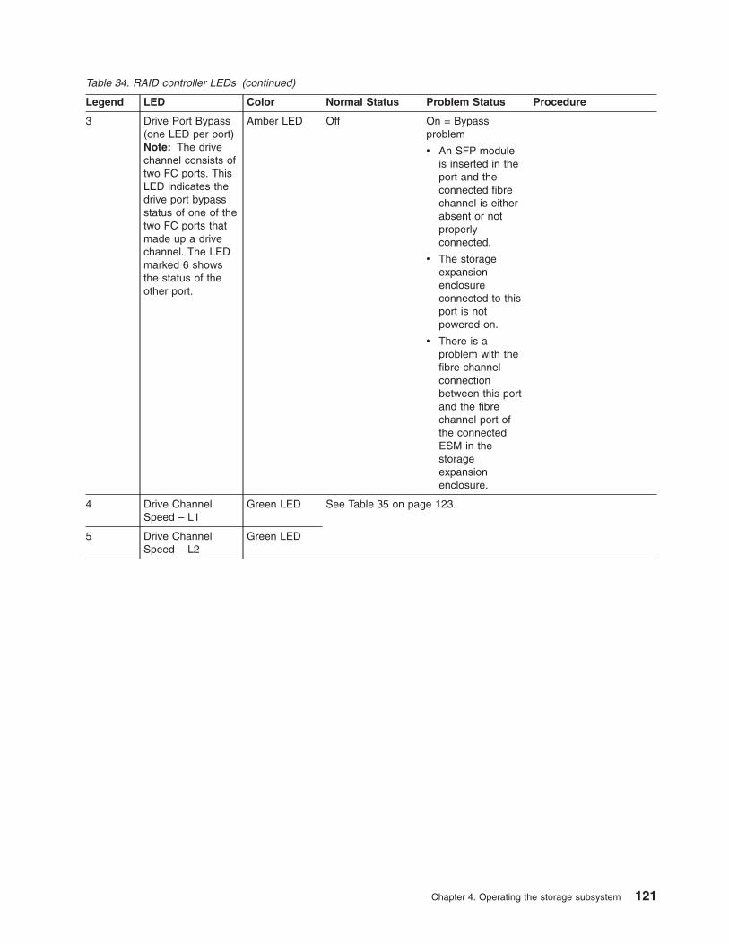
Table 34. RAID controller LEDs (continued)
Legend LED Color Normal Status Problem Status Procedure
3 Drive Port Bypass
(one LED per port)
Note: The drive
channel consists of
two FC ports. This
LED indicates the
drive port bypass
status of one of the
two FC ports that
made up a drive
channel. The LED
marked 6 shows
the status of the
other port.
Amber LED Off On = Bypass
problem
v An SFP module
is inserted in the
port and the
connected fibre
channel is either
absent or not
properly
connected.
v The storage
expansion
enclosure
connected to this
port is not
powered on.
v There is a
problem with the
fibre channel
connection
between this port
and the fibre
channel port of
the connected
ESM in the
storage
expansion
enclosure.
4 Drive Channel
Speed – L1
Green LED See Table 35 on page 123.
5 Drive Channel
Speed – L2
Green LED
Chapter 4. Operating the storage subsystem 121

Table 34. RAID controller LEDs (continued)
Legend LED Color Normal Status Problem Status Procedure
6 Drive Port Bypass
(one LED per port)
Note: The drive
channel consists of
two FC ports. This
LED indicates the
drive port bypass
status of one of the
two FC ports that
made up a drive
channel. The LED
marked 3 shows
the status of the
other port.
Amber LED Off On = Bypass
problem
v An SFP module
is inserted in the
port and the
connected fibre
channel is either
absent or not
properly
connected.
v The storage
expansion
enclosure
connected to this
port is not
powered on.
v There is a
problem with the
fibre channel
connection
between this port
and the fibre
channel port of
the connected
ESM in the
storage
expansion
enclosure.
7 Service Action
Allowed
Blue LED Off On = Safe to
remove
“Replacing a controller”
on page 145
8 Needs Attention Amber LED Off On = Controller
needs attention
There is a controller
fault or a controller
is offline.
“Troubleshooting the
storage subsystem” on
page 117
9 Cache Active Green LED On = Data in
cache
Off = No data in
cache
Not applicable
10 Ethernet Link
Speed
Green LED Off = 10BASE-T
On = 100BASE-T
Not applicable
122 IBM System Storage DS4800 Storage Subsystem: Installation, User’s, and Maintenance Guide
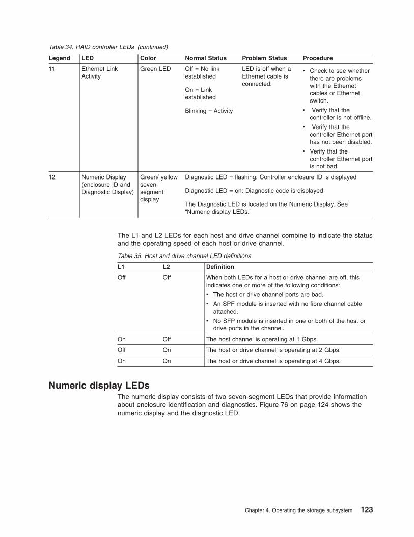
Table 34. RAID controller LEDs (continued)
Legend LED Color Normal Status Problem Status Procedure
11 Ethernet Link
Activity
Green LED Off = No link
established
On = Link
established
Blinking = Activity
LED is off when a
Ethernet cable is
connected:
v Check to see whether
there are problems
with the Ethernet
cables or Ethernet
switch.
v Verify that the
controller is not offline.
v Verify that the
controller Ethernet port
has not been disabled.
v Verify that the
controller Ethernet port
is not bad.
12 Numeric Display
(enclosure ID and
Diagnostic Display)
Green/ yellow
seven-
segment
display
Diagnostic LED = flashing: Controller enclosure ID is displayed
Diagnostic LED = on: Diagnostic code is displayed
The Diagnostic LED is located on the Numeric Display. See
“Numeric display LEDs.”
The L1 and L2 LEDs for each host and drive channel combine to indicate the status
and the operating speed of each host or drive channel.
Table 35. Host and drive channel LED definitions
L1 L2 Definition
Off Off When both LEDs for a host or drive channel are off, this
indicates one or more of the following conditions:
v The host or drive channel ports are bad.
v An SPF module is inserted with no fibre channel cable
attached.
v No SFP module is inserted in one or both of the host or
drive ports in the channel.
On Off The host channel is operating at 1 Gbps.
Off On The host or drive channel is operating at 2 Gbps.
On On The host or drive channel is operating at 4 Gbps.
Numeric display LEDs
The numeric display consists of two seven-segment LEDs that provide information
about enclosure identification and diagnostics. Figure 76 on page 124 shows the
numeric display and the diagnostic LED.
Chapter 4. Operating the storage subsystem 123

When the storage subsystem is operating normally, the numeric display shows the
enclosure identification (enclosure ID) of the storage subsystem and the diagnostic
LED flashes once every two seconds. The storage subsystem tray ID is normally
set at the factory to either values 85 or 00. Verify that the attached storage
expansion enclosures are not set to either of these enclosure IDs.
Note: It is not recommended, but you can set the storage subsystem enclosure ID
through the DS4000 Storage Manager software. The enclosure ID is an
attribute of the storage subsystem; both controllers display the same
enclosure ID. It is possible, however, that one controller will display the
enclosure ID, while the other controller displays a diagnostic code.
If an error has occurred and the controller Needs Attention LED is on, the numeric
display shows diagnostic information. The numeric display indicates the information
is diagnostic by illuminating an LED that appears as a decimal point between the
display numbers. The diagnostic LED tuns off when the numeric display shows the
storage subsystem enclosure ID. The numeric display shows various diagnostic
codes as the controllers perform the startup process after each power cycle or
reset. After diagnostics are complete, the current storage subsystem enclosure ID is
displayed.
Diagnostic codes in the form of Lx, where x is a hexadecimal digit, indicate
controller state information. In general, these codes are displayed only when the
controller is in a non-operational state. The controller might be non-operational due
to a configuration problem (such as mismatched controller types), or it might be
non-operational due to hardware faults. If the controller is non-operational due to
system configuration, the controller Needs Attention LED is off. If the controller is
non-operational due to a hardware fault, the controller Needs Attention LED is on.
The definitions for Lx diagnostic codes are listed in Table 36 on page 125.
76041
Diagnostic LED
Seven-segmentdisplay
ds48042
Figure 76. Numeric display LEDs
124 IBM System Storage DS4800 Storage Subsystem: Installation, User’s, and Maintenance Guide

Table 36. Numeric display diagnostic codes
Value Controller State Description
Storage Manager
View
L0 Suspend Mismatched controller
types
Needs Attention
condition for board
type mismatch
L1 Suspend Missing
interconnect-battery
unit
Needs Attention
condition for missing
interconnect-battery
unit
L2 Suspend Persistent memory
errors
Needs Attention
condition for offline
controller
L3 Suspend Persistent hardware
errors
Needs Attention
condition for offline
controller
L4 Suspend Persistent data
protection errors
Needs Attention
condition for offline
controller
88 Reset Controller is held in
reset by alternate
controller
Power supply-fan LEDs
The LED positions on the right and left power supply and fan units are in mirror
positions. The five LED positions for the left power supply and fan unit are aligned
vertically on the right side of the unit. The five LED positions for the right power
supply and fan unit are aligned vertically, on the left side of the unit. On the left
power supply and fan unit, from top to bottom, the LEDs are: Service Action
Allowed LED, Needs Attention LED, Battery 1 charging LED, Battery 2 charging
LED, and the Power LED. On the right power supply and fan unit, from bottom to
top, the LEDs are: Service Action Allowed LED, Needs Attention LED, Battery 1
charging LED, Battery 2 charging LED, and the Power LED
Note: The right power supply and fan unit is linked with RAID controller A. The left
power supply and fan unit is linked with RAID controller B in the DS4800.
Chapter 4. Operating the storage subsystem 125
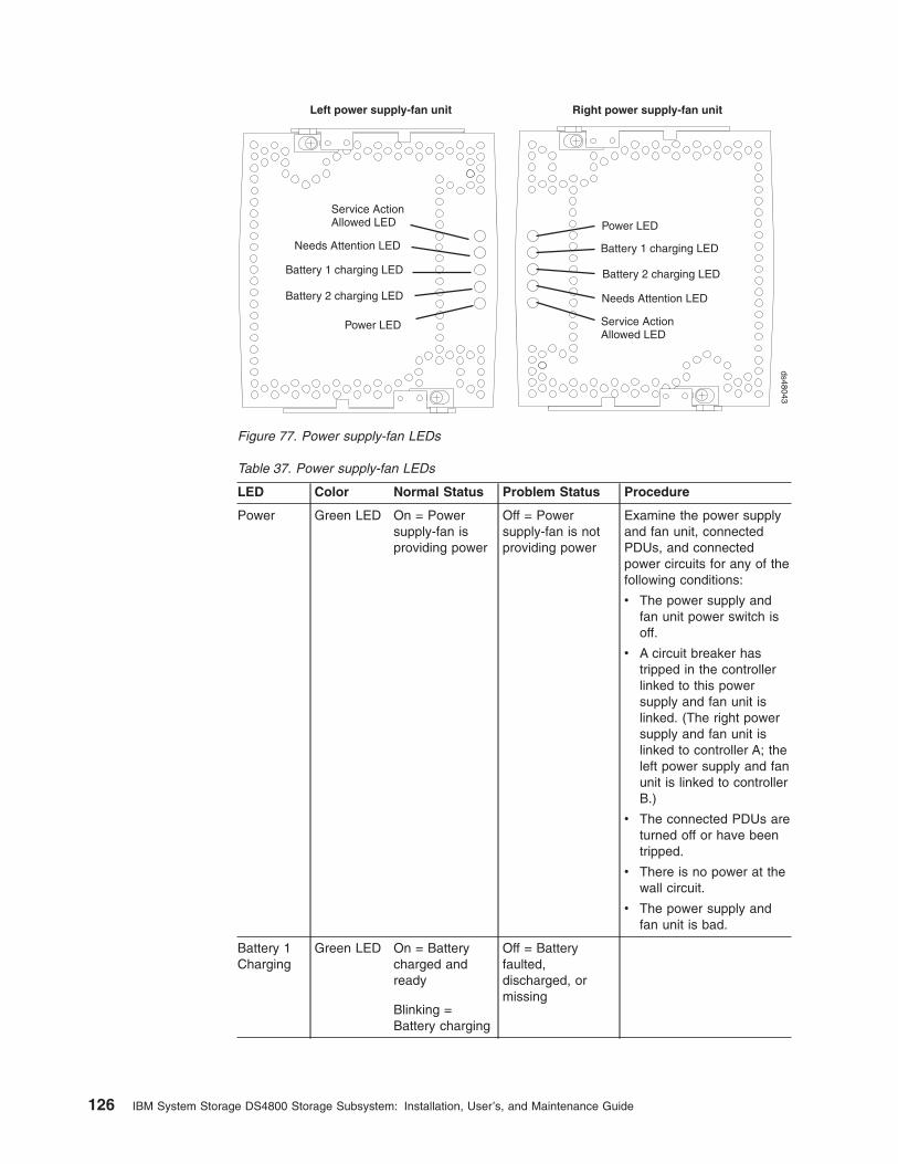
Table 37. Power supply-fan LEDs
LED Color Normal Status Problem Status Procedure
Power Green LED On = Power
supply-fan is
providing power
Off = Power
supply-fan is not
providing power
Examine the power supply
and fan unit, connected
PDUs, and connected
power circuits for any of the
following conditions:
v The power supply and
fan unit power switch is
off.
v A circuit breaker has
tripped in the controller
linked to this power
supply and fan unit is
linked. (The right power
supply and fan unit is
linked to controller A; the
left power supply and fan
unit is linked to controller
B.)
v The connected PDUs are
turned off or have been
tripped.
v There is no power at the
wall circuit.
v The power supply and
fan unit is bad.
Battery 1
Charging
Green LED On = Battery
charged and
ready
Blinking =
Battery charging
Off = Battery
faulted,
discharged, or
missing
Power LED
Battery 1 charging LED
Battery 2 charging LED
Needs Attention LED
Service ActionAllowed LED
Power LED
Battery 1 charging LED
Needs Attention LED
Service ActionAllowed LED
Battery 2 charging LED
Right power supply-fan unitLeft power supply-fan unitds48043
Figure 77. Power supply-fan LEDs
126 IBM System Storage DS4800 Storage Subsystem: Installation, User’s, and Maintenance Guide

Table 37. Power supply-fan LEDs (continued)
LED Color Normal Status Problem Status Procedure
Battery 2
Charging
Green LED On = Battery
charged and
ready
Blinking =
Battery charging
Off = Battery
faulted,
discharged, or
missing
Needs
Attention
Amber LED Off On = Power
supply-fan needs
attention
“Troubleshooting the
storage subsystem” on
page 117
Service
Action
Allowed
Blue LED Off On = Safe to
remove
“Resetting the controller
circuit breakers” on page
131
“Replacing a power supply
and fan unit” on page 152
Interconnect-battery unit LEDs
Table 38. Interconnect-battery unit LEDs
Legend LED Color Normal Status Problem Status/Procedure
�1� Battery
Needs
Attention
Amber LED Off On = Battery failed
See “Replacing a backup battery
pack” on page 160.
Figure 78. Interconnect-battery unit LEDs
Chapter 4. Operating the storage subsystem 127

Table 38. Interconnect-battery unit LEDs (continued)
Legend LED Color Normal Status Problem Status/Procedure
�2� Power Green LED On = storage
subsystem is
powered on
Off = storage subsystem is
powered off
If the storage subsystem is
powered on but this LED remains
off, examine the power supply and
fan units, the connected PDUs,
and the connected power circuits
for any of the following conditions:
v Both power supply and fan units
are not turned on.
v A circuit breaker has tripped.
v The connected PDUs are turned
off or have been tripped.
v There is no power at the wall
circuit.
v The interconnect-battery unit is
bad.
�3� Overall
DS4800
Configuration
Needs
Attention
Amber LED Off On = A component in the storage
subsystem configuration has
developed a fault.
Inspect the Needs Attention LEDs
on the other components in the
DS4800 Storage Subsystem and in
all connected DS4000 storage
expansion enclosures to isolate the
fault.
However, it is recommended that
you use the DS4000 Storage
Manager Subsystem Management
window to identify the cause of the
problem and use the Recovery
Guru to help fix the problems.
Some of the problems may not
cause the Needs Attention LED on
the individual CRU to light, but
they will cause this Overall
DS4800 Configuration Needs
Attention LED to light. For
example, a hard disk drive that
exceeds its PFA errors will cause
this LED to light, but the drive
Needs Attention LED for the
individual drive in the attached
storage expansion enclosure will
not light.
See “Troubleshooting the storage
subsystem” on page 117.
128 IBM System Storage DS4800 Storage Subsystem: Installation, User’s, and Maintenance Guide

Table 38. Interconnect-battery unit LEDs (continued)
Legend LED Color Normal Status Problem Status/Procedure
�4� Locate/
Identify
White LED
Note: This
LED is
shown as
blue (and
displayed in
a different
order) when
the DS4800
bezel is
installed.
See “Front
bezel LEDs”
on page
118.
Off On = storage subsystem locate
�5� Service
Action
Allowed
Blue LED Off On = Safe to remove
See “Replacing the
interconnect-battery unit” on page
156.
�6� Battery
Needs
Attention
Amber LED Off On = Battery failed
See “Replacing a backup battery
pack” on page 160.
The Power, Overall DS4800 Configuration Needs Attention, and Locate LEDs are
general indicators for the entire DS4800 storage subsystem (or configuration, in the
case of the Overall DS4800 Configuration Needs Attention), not specifically for the
interconnect-battery unit. The Overall DS4800 Configuration Needs Attention LED
turns on if a fault condition is detected in any component in the storage subsystem
configuration, including all attached storage expansion enclosures. The Power,
Overall DS4800 Configuration Needs Attention, and Locate LEDs shine through the
front bezel.
Attention: If the Overall DS4800 Configuration Needs Attention LED lights, refer
to the DS4000 Storage Manager client software to determine the problem with the
storage subsystem. Also, inspect the Needs Attention LEDs on the other
components in the storage subsystem to help isolate the fault to a specific
component.
Recovering from an overheated power supply and fan unit
The storage subsystem has two power supply and fan units. Each power supply
and fan unit contains a power supply, a cooling fan, a battery charger, and a built-in
temperature sensor designed to prevent the power supplies from overheating.
Under normal operating conditions, with an ambient air temperature range of 10° C
to 35° C (50° F to 95° F), the cooling fans maintain a proper operating temperature
inside the storage subsystem.
Several factors can cause the power supplies to overheat. These factors include the
following:
v Unusually high room temperature
v Fan failure
Chapter 4. Operating the storage subsystem 129

v Defective circuitry in the power supply
v Blocked air vent
v Failure in other devices installed in the cabinet
If the internal temperature rises above 70° C (158° F), one or both power supplies
automatically shut down. If one power supply shuts down, the DS4000 Storage
Manager client software displays a Needs Attention status in the Subsystem
Management window, the alarm sounds (if enabled), and the Overall DS4800
Configuration Needs Attention LED on the front bezel of the storage subsystem
turns on.
If a common environmental stress causes both power supplies to shut down, the
storage subsystem shuts down, and the DS4000 Storage Manager client software
displays a Not Responding status in the Subsystem Management window.
If event monitoring is enabled and event notification is configured, the software also
issues critical event notifications.
v Nominal temperature exceeded – The storage subsystem temperature exceeds
the normal operating range.
v Maximum temperature exceeded – The storage subsystem temperature exceeds
70° C (158° F).
Use the following procedure to resume normal operation after a power supply
shutdown.
Attention: Power supplies automatically shut down when air temperature inside
the cabinet reaches 70° C (158° F) or above. If the power supplies have shut down,
immediately remove all cabinet panels to help cool the cabinet air temperature and
prevent damage to the storage subsystem.
Note: If both power supply and fan units have shut down, start with step 4 below.
1. If applicable, turn off the alarm.
2. Use the DS4000 Storage Manager client software to print a storage subsystem
profile.
3. In the DS4000 Storage Manager client Subsystem Management window, select
Advanced � Troubleshooting � View Event Log to display the DS4800
critical events. Look for one of the following critical event entries:
v Event 281B - Nominal temperature exceeded
v Event 281C- Maximum temperature exceeded
4. Try alleviating the overheating problem by doing the following:
v Removing all panels from the cabinet.
v Cooling the area using external fans.
v Shutting down the power to the storage subsystem or storage expansion
enclosures (Follow the power-down procedure described in “Turning off the
storage subsystem” on page 108.)
5. Stop all I/O activity to the storage subsystem and to all attached storage
expansion enclosures.
6. Wait until the ambient air temperature around the storage subsystem cools.
The storage subsystem is capable of power-up recovery without operator
intervention after the temperature inside the power supply and fan unit cools to
below 70° C (158° F). After the air has cooled, the power supplies should turn
on automatically. If the power supplies restart automatically, the controllers
reset and return to normal operation.
130 IBM System Storage DS4800 Storage Subsystem: Installation, User’s, and Maintenance Guide

7. Did the power supplies restart automatically?
v Yes – Go to step 9.
v No – Go to step 8.
8. Turn off the power switch on each controller in the storage subsystem and
then power off all connected storage expansion enclosures. Wait 1 minute and
then turn on power to all connected storage expansion enclosures and then to
the storage subsystem. If the power supplies go into operation, go to step 9. If
not, call your IBM service representative.
9. Check the status LEDs on the front and back of the storage subsystem.
For information about storage subsystem LEDs, see “Checking the LEDs” on
page 118.
10. Are the LEDs on the storage subsystem indicating normal status?
v Yes – Go to step 11.
v No – Go to step 12.
11. Use the DS4000 Storage Manager client software to check the status of all
storage subsystems in the configuration. Is the status Optimal for each storage
subsystem?
v Yes – End of procedure. Resume normal operation.
v No – Go to step 12.
12. Diagnose and correct the fault by completing the following steps.
a. Select the Recovery Guru toolbar button in the Subsystem Management
window to run the Recovery Guru.
b. Complete the recovery procedure.
If the Recovery Guru directs you to replace a failed component, use the
individual LEDs on the storage subsystem to locate the specific failed
component.
c. When the procedure is completed, select Recheck in the Recovery Guru.
This will rerun the Recovery Guru to ensure that the problem has been
fixed.
d. If the problem has not been fixed contact your IBM service representative.
Print a storage subsystem profile and save the storage subsystem support
data. The profile and support data will be helpful when troubleshooting
storage subsystem problems. (For information about printing a storage
subsystem profile and saving the support data, refer to the Subsystem
Management window online help.)
Resetting the controller circuit breakers
Each storage subsystem controller has two circuit breakers that provide
over-current protection to the power supply in a power supply and fan unit. The
circuit breakers are mounted inside the controller, in line with the internal power
cable. One circuit breaker provides protection for AC input, and the second circuit
breaker provides protection for DC input.
Note: DC power input is not currently supported for the DS4800. Contact your IBM
service representative or reseller for information about possible future
support for DC power input.
The internal power cable runs from the AC connector on a controller to the power
supply in a power supply and fan unit. Power to the right power supply and fan unit
(as viewed from the front of the storage subsystem) is routed through the top
Chapter 4. Operating the storage subsystem 131

controller (controller A); power to the left power supply and fan unit is routed
through the bottom controller (controller B).
If a circuit breaker has tripped, the condition might appear as if a power supply and
fan unit has failed. The power supply is no longer providing power to the storage
subsystem. A tripped circuit breaker is indicated when all of the following conditions
are present:
v The Overall DS4800 Configuration Needs Attention LED on the storage
subsystem front bezel is turned on.
v The controller Needs Attention LEDs are not turned on.
v The power supply and fan unit Needs Attention LEDs are not turned on.
v The Service Action Allowed LED is turned on for the power supply and fan unit
connected to the controller with the open circuit breaker.
v The DS4000 Storage Manager client shows the power supply and fan unit has
failed.
Use the following procedure to reset the circuit breaker.
Tools and Equipment
v Antistatic protection
v Nonconducting stylus
Electrostatic discharge can damage sensitive components – Touching the
storage subsystem or its components without using a proper ground might damage
the equipment. To avoid damage, use proper antistatic protection while handling
any components.
1. If the alarm is sounding, turn off the alarm.
2. Check to ensure that the external power cables are completely plugged into
the controllers and into the power source.
3. Put on antistatic protection.
4. Remove the front bezel by grasping the sides and pulling the cover toward
you.
5. Check the Needs Attention LED on each power supply and fan unit. (Figure 79
on page 133 shows the left power supply and fan unit Service Action Allowed
LED is the top, or first, LED, and the Needs Attention LED is the second LED.
On the right power supply and fan unit the Service Action Allowed LED is the
bottom, or fifth LED, and the Needs Attention LED is the next, or fourth, LED.)
132 IBM System Storage DS4800 Storage Subsystem: Installation, User’s, and Maintenance Guide

Is a power supply and fan unit Needs Attention LED on?
v Yes – A power supply and fan unit has failed. To replace the failed power
supply and fan unit, see “Replacing a power supply and fan unit” on page
152.
v No – Go to step 6 on page 134.
Attention: Fiber-optic cables are fragile. Bending, twisting, folding, or
pinching fiber optic cables can cause damage to the cables, degraded
performance, or data loss. To prevent damage, do not twist, fold, pinch, or step
on the cables. Do not bend the cables in less than a 2-inch radius.
Note: You do not need to remove the interface cables from the controllers to
reset the circuit breakers; however, IBM recommends that you remove
the cables to make this procedure easier. If you choose to remove the
interface cables, ensure that you label each cable so that you can
reconnect them correctly to the controller. Figure 80 on page 134
identifies all of the connectors on the back of the controller.
Needs Attention LED
Service ActionAllowed LED
Needs Attention LED
Service ActionAllowed LED
Right power supply-fan unitLeft power supply-fan unitds48046
Figure 79. Power supply-fan Needs Attention LEDs
Chapter 4. Operating the storage subsystem 133

6. Use the DS4000 Storage Manager client software to take the controller offline.
After the controller is offline, the Service Action Allowed LED turns on, and you
can safely remove the controller.
7. Slide the controller with the open circuit breaker from the storage subsystem.
You do not need to completely remove the controller. Only slide it out far
enough to reveal the holes over the circuit breakers.
a. Using your index fingers, simultaneously push the latches to release the
levers, and rotate the levers to disengage them from the locking pins.
b. Use the levers to slide the controller from the storage subsystem chassis.
(Figure 81 on page 135 shows a controller sliding from the storage
subsystem chassis.)
Host channels
RS-232serial port
Ethernet ports Dual-porteddrive channels
ACpower DC
power
Host channels
RS-232serial portEthernet ports
Dual-porteddrive channels
ACpowerDC
power
Controller A
Controller B
Strain-reliefclamp
Strain-reliefclamp
ds48015
Figure 80. RAID controller connections
134 IBM System Storage DS4800 Storage Subsystem: Installation, User’s, and Maintenance Guide

8. Insert a nonconducting stylus through the appropriate hole in the cover of the
controller and press down gently. One hole is over the AC circuit breaker, a
second hole is over the DC circuit breaker. (DC is not currently supported for
the DS4800.) Figure 82 shows the location of the circuit breaker access holes
in the controller B cover.
Note: When controllers A and B are inserted in their respective controller slots
in the DS4800, the location of the circuit breaker access holes are as
follows. On controller A, the circuit breaker access holes are located on
the left side on the bottom of the controller. On controller B, the circuit
breaker access holes are located on the right side on the top of the
controller (as shown in Figure 82).
RAID controllers
Levers in releasedposition
Latches
ds48045
Figure 81. Removing the controller from the storage subsystem
AC circuit breaker
DC circuit breaker
ds48044
Figure 82. Circuit breaker access holes
Chapter 4. Operating the storage subsystem 135

9. Reset the circuit breaker that tripped by pressing down with the stylus on the
rocker switch.
10. Slide the controller into the storage subsystem chassis.
a. Holding both levers, slowly push the controller until the notches in both the
left and right levers are aligned with the pins on the DS4800 enclosure so
that the controller is pulled evenly into the DS4800 storage subsystem
chassis, ensuring full electrical connection contact on all interface pins.
Attention: Verify that the controller does not snag any other DS4800
cables when you slide it into the controller bay.
b. Press the controller fully into the slot, engaging the pins on the enclosure.
c. Hold open both latches and push both left and right levers simultaneously
to the closed position. Release the latches. When you release the latches,
you should hear both latches snap over the levers, indicating that the
component is locked in place.
11. If you removed the interface cables, reconnect all host interface cables and
drive interface cables, including the SFP modules.
12. Wait up to 5 minutes for the DS4000 Storage Manager client software to
recognize the controller.
13. Complete any remaining Recovery Guru procedures for controller replacement,
if needed.
14. Based on the Host Channel Speed, Drive Channel Speed, and Needs
Attention LED status, proceed to one of the following steps:
v All channel speed LEDs are on and the Needs Attention LED is off – Go to
step 16.
v All channel speed LEDs are off or the Needs Attention LED is on – Verify
the controller has been installed correctly. Remove and reinstall the
controller. Go to step 15.
Note: If a host channel or drive channel does not have a cable connected,
the channel speed LEDs are not illuminated.
15. Did this action correct the problem?
v Yes – Go to step 16.
v No – If the problem has not been fixed, contact your IBM service
representative.
16. Remove the antistatic protection.
17. Install the front bezel by aligning the pins on the storage subsystem chassis
with the spring-steel retainers on the cover and then pressing the cover toward
the chassis until the pins snap into place.
18. Using the Enterprise Management window, view the status of the storage
subsystems. Do any storage subsystems indicate Needs Attention?
v Yes – Go to step 19.
v No – All components display Optimal status. You are finished with this
procedure.
19. Use the Subsystem Management window to check the status of all storage
subsystems in the configuration.
20. Do any storage subsystems have a Overall DS4800 Configuration Needs
Attention status?
a. Yes – Select the Recovery Guru toolbar button in the Subsystem
Management window, and complete the recovery procedure. If the problem
persists, contact your IBM service representative.
136 IBM System Storage DS4800 Storage Subsystem: Installation, User’s, and Maintenance Guide

b. No – Contact your IBM service representative. Print a storage subsystem
profile, and save the storage subsystem support data. The profile and
support data are helpful when troubleshooting storage subsystem
problems. (For information about printing a storage subsystem profile and
saving the support data, refer to the Subsystem Management window
online help.)
Cache memory and cache battery
Each RAID controller in the DS4800 Storage Subsystem contains either 2 GB, 4
GB, or 8 GB of cache memory to store read and write operations. (Both RAID
controllers in the DS4800 must have the same amount of cache memory.) The
interconnect-battery unit contains two Lithium Ion battery packs that can maintain
the data in the RAID controller caches for up to three days in the event that the
DS4800 Storage Subsystem loses power.
Important:
Do not replace the battery until it is marked failed by the controller. If the batteries
are shown as expired, use the reset battery age function in the SM client
subsystem management window to reset the age.
Attention: There are different replacement FRU part numbers for the DS4800
controller with certain cache sizes. The DS4800 storage subsystem profile has the
information on the installed cache memory size in the DS4800 controllers. Refer to
the storage subsystem profile and see “Parts list” on page 174 for the correct FRU
part number for the DS4800 controller. In addition, the DS4800 model 80A/H has
different replacement FRU part numbers than the DS4800 model 82A/H controllers,
even though they both have the same cache size.
Cache memory
Cache memory is memory on the RAID controller that is used for intermediate
storage of read and write data on the DS4800 RAID controllers. Using cache
memory can increase system performance. The data for a read operation from the
host might be in the cache memory from a previous operation (thus eliminating the
need to access the drive itself), and a write operation is completed when it is written
to the cache, rather than to the drives.
The RAID controller has a Cache Active LED that displays the current status of the
cache. The LED is on if there is data in the cache, and it is off if there is no data in
the cache.
If caching is enabled and the Cache Active LED never comes on during I/O activity,
it indicates one of the following conditions:
v The cache memory from either controller A or controller B has failed.
v The cache sizes in controller A and controller B are not the same.
v The battery has failed. (In this case, one or both of the green Battery LEDs will
be off and one or both amber Battery Needs Attention LEDs will be lit.)
Note: Always use the DS4000 Storage Manager client to check your cache
memory settings before assuming a hardware failure.
Figure 83 on page 138 shows the locations of the Cache Active LEDs on the front
of the RAID controllers.
Chapter 4. Operating the storage subsystem 137

Subsystem cache battery
The DS4800 interconnect-battery unit contains two battery packs that provide
backup power to maintain any cached data not written to disks in the event of a
power loss. The battery packs can provide power to the data caches in the RAID
controllers for up to three days.
Statement 2:
CAUTION:
When replacing the lithium battery, use only an equivalent type battery
recommended by the manufacturer. If your system has a module containing a
lithium battery, replace it only with the same module type made by the same
manufacturer. The battery contains lithium and can explode if not properly
used, handled, or disposed of.
Do not:
v Throw or immerse into water
v Heat to more than 100° C (212° F)
v Repair or disassemble
Dispose of the battery as required by local ordinances or regulations.
Replace the battery packs in the DS4800 interconnect-battery unit when they are
identified as failing by the DS4000 Storage Manager Subsystem Management
window, or when the Battery LEDs or Battery Needs Attention LEDs light. (These
LEDs are located on the power supply and fan units and on the interconnect-battery
unit respectively, as shown in Figure 84 on page 139.)
Controller A
Controller B
Cache active LEDCache active LED
ds48010
Figure 83. Cache Active LEDs
138 IBM System Storage DS4800 Storage Subsystem: Installation, User’s, and Maintenance Guide

Replace only the battery pack that is indicated as failed by the LEDs or in the
DS4000 Storage Manager Subsystem Management window. You do not need to
replace both battery packs when the Battery LEDs indicate that only one battery
pack has failed.
In the event that the battery age expires, do not call on IBM technical support to
replace the battery. Instead, reset the battery age using the procedure described in
the Storage Manager online help. You should only replace the battery when it is in a
failed state, as reported by the Storage Manager Recovery Guru.
Note: Controller firmware version 6.14.xx.xx does not provide the Storage Manager
menu option to reset the battery age. This option is available with controller
firmware version 6.15.xx.xx or later.
Each power supply and fan unit has green Battery LEDs on the back that indicates
the battery status of each battery pack, as follows:
v The LED is on and remains steady when the battery is fully charged.
v The LED flashes when the battery is charging or performing a self-test.
v The LED is off if the battery or the battery charger has failed.
The interconnect-battery unit also has a battery failure indicator LED for each
battery pack that is located on the interconnect-battery unit. This LED will light if the
battery fails to hold a charge.
The battery performs a self-test at startup and every 25 hours thereafter (during
which time the Battery LED flashes). If necessary, the battery begins recharging at
that time. If the battery fails the self-test, the Battery LED turns off, indicating a
battery fault.
Data caching starts after the battery completes the startup tests.
Attention: Write caching is suspended while a battery pack is either charging or
self-testing.
Figure 84 shows the location of the Battery LEDs and the Battery Needs Attention
LEDs on the power supply and fan units and the interconnect-battery unit.
Battery 1 LED
Battery 2 LEDBattery 1 LED
Battery 2 LED
Battery Needs Attention LED Battery Needs Attention LED
ds48011
Figure 84. Battery LEDs
Chapter 4. Operating the storage subsystem 139

140 IBM System Storage DS4800 Storage Subsystem: Installation, User’s, and Maintenance Guide

Chapter 5. Replacing components
This chapter lists replacement parts and explains the procedures for replacing a
controller, a power supply and fan unit, an interconnect-battery unit, and an SFP
module. Before using the procedures in this chapter, perform the appropriate
troubleshooting steps described in “Troubleshooting the storage subsystem” on
page 117, and in the Recovery Guru.
The following list shows the components that you can replace on site. To order
parts, contact your IBM service representative.
v RAID controllers
v Power supply-fans (containing power supplies, fans, and battery chargers)
v Interconnect-battery unit (containing the midplane and batteries for the cache
backup)
v SFP modules
v Interface cables
v Ethernet cables
Attention: Never remove the interconnect-battery unit unless directed to do so by
an IBM Service representative. Refer to “Replacing the interconnect-battery unit” on
page 156 for complete information about the conditions required for safe removal of
the interconnect-battery unit.
This chapter also provides instructions to help you add new DS4000 storage
expansion enclosures to existing DS4800 configuration.
You can perform all replacement procedures in this chapter as hot-swap
procedures. Hot swap refers to the ability to remove and replace a storage
subsystem component while the storage subsystem is under power and processing
data. The DS4800 Storage Subsystem has three major components you can
replace on site: the controller, power supply and fan unit, and interconnect-battery
unit. In a fully configured storage subsystem, the controllers and power supply and
fan units are redundant. If any one of these redundant components fails, the
component can be replaced without powering off the storage subsystem, and
without interrupting data processing.
For more CRU and Option part number information, see the following Web site:
www.ibm.com/servers/storage/support/disk/
Handling static-sensitive devices
Attention: Static electricity can damage electronic devices and your system. To
avoid damage, keep static-sensitive devices in their static-protective packages until
you are ready to install them.
To reduce the possibility of electrostatic discharge, observe the following
precautions:
v Limit your movement. Movement can cause static electricity to build up around
you.
v Handle the device carefully, holding it by its edges or its frame.
v Do not touch solder joints, pins, or exposed printed circuitry.
© Copyright IBM Corp. 2006, 2007 141

v Do not leave the device where others can handle and possibly damage the
device.
v While the device is still in its static-protective package, touch it to an unpainted
metal part of the storage subsystem for at least two seconds. This drains static
electricity from the package and from your body.
v Remove the device from its package and install it directly into your storage
subsystem without setting it down. If it is necessary to set the device down, place
it in its static-protective package. Do not place the device on your storage
subsystem cover or any metal surface.
v Take additional care when handling devices during cold weather because heating
reduces indoor humidity and increases static electricity.
Service Action Allowed status LED
Each controller, power supply and fan unit, and interconnect-battery unit has a blue
Service Action Allowed status LED. The purpose of the Service Action Allowed
status LED is to help ensure that a component is not removed before it is safe to
do so. Do not remove any DS4800 component unless the component’s Service
Action Allowed status LED is lit.
Attention
Never remove a controller, power supply and fan unit, or interconnect-battery
unit unless the Service Action Allowed status LED is turned on. Doing so can
result in a potential loss of data. If the Needs Attention LED is lit and the
associated Service Action Allowed status LED is not lit, then you must perform
additional diagnostics before you can remove the indicated component. Use
the Recovery Guru instructions in the DS4000 Storage Manager Subsystem
Management window or refer to the appropriate component replacement
instructions in this chapter for the additional diagnostics required in this case.
The Service Action Allowed status LED automatically turns on or off as conditions
change. Wait at least two minutes after you replace each component for the
controller to recognize the new component and update the LED status. In most
cases when a single component fails, the Service Action Allowed status LED turns
on steadily when the Needs Attention status LED is turned on for the component.
The following sections discuss the behavior of the Service Action Allowed status
LED in cases of single and multiple component failures.
Single component failures
When a single component in the DS4800 has failed, the following list indicates the
behavior of the Service Action Allowed status LED lights:
v If a controller or power supply and fan unit fails and needs to be replaced, the
amber Needs Attention status LED on that component turns on to indicate that a
service action is required. If there are no data availability dependencies or other
conditions that dictate that the component should not be removed, the blue
Service Action Allowed status LED turns on. Do not remove any components
other than the component indicated by the lit blue Service Action Allowed status
LED.
v The interconnect-battery unit contains the mid-plane that communicates between
controllers A and B in the DS4800 Storage Subsystem. If the interconnect-battery
unit needs to be replaced, the Service Action Allowed status LED does not
142 IBM System Storage DS4800 Storage Subsystem: Installation, User’s, and Maintenance Guide

automatically turn on. Before the interconnect-battery unit Service Action Allowed
status LED can turn on, you must use the DS4000 Storage Manager client to
place controller B offline. (Controller A is the controller designated to receive all
I/O activity when the interconnect-battery unit is removed from the DS4800.) By
placing controller B offline, you route all controller and I/O activity through
controller A. This maintains data availability while the interconnect-battery unit is
removed, preventing any problems that would normally arise from the loss of
communication between controllers A and B.
Attention: Before you remove the interconnect-battery unit, you must verify
that controller A is in an optimal state, and the power supply and fan unit CRU
that is connected to controller A (the right power supply) is optimal. Never
remove the interconnect-battery unit when controller A or the power supply and
fan unit CRUs are not in an optimal state.
Multiple component failures
When multiple components in the DS4800 have failed, the behavior of the Service
Action Allowed and Needs Attention LEDs can vary from situation to situation. In
some cases, multiple Service Action Allowed status LEDs light when their
corresponding Needs Attention LEDs are lit. In other cases, none of the Service
Action Allowed status LEDs light when their corresponding Needs Attention LEDs
are lit. This variance exists because the ability to remove a component depends on
the different data availability dependencies of the storage subsystem components.
If replacing any one of the multiple components that have their Needs Attention
LEDs lit will cause the DS4800 Storage Subsystem to shut down, the Service
Action Allowed status LEDs will not light on any of the components that need
attention. For example, if both the right power supply and fan unit (which is linked to
controller A) and controller B need attention, then neither of the Service Action
Allowed status LEDs on these components would light. Removing the controller B
before replacing the failed right power supply and fan unit would cause controller A
to lose power, resulting in a loss of data availability. (This linkage exists because
the power distribution from each power supply and fan unit runs through the
controller physically connected to that power supply and fan unit.)
However, if replacing any one of the multiple components that have their Needs
Attention LEDs lit will not cause the DS4800 Storage Subsystem to shut down, then
the Service Action Allowed status LEDs will light on all of the components that need
attention. For example, if the right power supply and fan unit (which is linked to
controller A) and controller A both need attention, then the Service Action Allowed
status LEDs on both of these components would light, indicating that either
component can be replaced first.
Important: In this situation (in which replacing any one of the multiple components
that have their Needs Attention LEDs lit will not cause the DS4800
Storage Subsystem to shut down), after you remove one failed
component, the Service Action Allowed status LEDs on the remaining
components that need attention might turn off. This change in the
Service Action Allowed status LEDs indicates that removing additional
components now might cause the storage subsystem to shut down.
For example, if both power supply and fan units have failed, the Needs
Attention and the Service Action Allowed status LEDs would be lit for
both components. However, when you remove one power supply and
fan unit from the system, the Service Action Allowed status LED on the
remaining power supply and fan unit turns off, indicating that you now
Chapter 5. Replacing components 143

cannot remove the second power supply and fan unit (because the
storage subsystem requires that at least one power supply and fan unit,
functioning or not, must be present in the storage subsystem at all
times).
Releasing a component lever
Each component is secured into the storage subsystem chassis by two cam lock
levers mounted to the component. The lever engages with a pin on the storage
subsystem chassis to pull the component securely into the chassis. The levers are
locked in place by spring-loaded latches. The control components have the levers
on the same side. The power supply and fan units and the interconnect-battery unit
have the one lever mounted to the top of the component and one lever mounted to
the bottom of the component. Figure 85 shows a component lever and the latch that
secures the lever. The top view shows the lever in the closed and latched position.
The bottom view shows the lever in the released position.
To release both latches on a component and remove the component, complete the
following:
1. Push the latches to the side until the latches release the levers. Do not proceed
with the next step until you have released both levers from the latches.
2. Rotate both levers out simultaneously. Ensure that the levers are completely
free of the pins. Then place one hand under the component and use the levers
to pull the component from the DS4800 Storage Subsystem.
To replace a component and lock the latches, complete the following:
Latch
Lever
Pin
ds48024
Figure 85. Component lever and latch
144 IBM System Storage DS4800 Storage Subsystem: Installation, User’s, and Maintenance Guide

1. With both levers rotated out perpendicular to the face of the component, slide
the back of the component into the appropriate slot.
2. Push the component into the slot and, when the component is almost fully
installed, verify that the notches in both levers are aligned with the pins on the
storage subsystem. Verify this alignment to ensure that the component is pulled
evenly into the storage subsystem, ensuring full electrical connection contact on
all interface pins.
3. Press the component fully into the slot, engaging the pins on the storage
subsystem.
4. Hold open both latches and rotate both levers simultaneously to the closed
position. Release the latches. When you release the latches, you should hear
both latches snap over the levers. This indicates that the component is locked in
place.
Replacing a controller
Attention: Before you replace a RAID controller, verify the following:
v The replacement RAID controller part number matches the part number of the
RAID controller to be replaced. To provide full functionality, the two controllers
should have the same memory capacity. Although two controllers of different
memories can be paired in an storage subsystem, the mismatch causes some
functions to be disabled (for example, the cache mirroring function).
v Inserting a DS4800 model 80A/H controller into a non-model 80A/H DS4800
subsystems (that is, model 82A/H, model 84A/H, model 88A/H) will result in the
controller to be held in lockdown state. Similarly, inserting a non-model 80
DS4800 controller into a DS4800 model 80 subsystem will cause it to be held in
lock down state.
v Both power supply and fan units must be connected and powered on with no
lighted Needs Attention LEDs. Ensure that the Power LEDs on each of the power
supply and fan units are lit. If either of the power supply and fan units is not
optimal, it is recommended that you replace that component before you proceed
with the controller replacement procedure.
v If you are replacing an optimal controller, first make sure that the other RAID
controller is optimal and that the fibre channel path from the hosts to the other
RAID controller is also optimal.
Use the following procedure to replace a controller in an DS4800 Storage
Subsystem.
Attention: If you are upgrading controllers you received through an upgrade kit,
refer to “Upgrading controllers” on page 150 and use the instructions provided in
the upgrade kit to replace the controllers instead of the instructions in this section.
Each RAID controller has a unique hardware Ethernet address, which is printed on
a label on the front.
1. Use the DS4000 Storage Manager client software to print a storage subsystem
profile. Move logical drive ownership to the other controller. If the controller you
are replacing has failed but is still operating, move the failed controller to an
Offline state.
Attention: Never remove a controller unless the Service Action Allowed
status LED is turned on. Doing so can result in a potential loss of data.
2. Locate the failed controller by checking the Needs Attention status LEDs on
the controllers in the storage subsystem. (Figure 86 on page 146 shows the
Chapter 5. Replacing components 145

location of the Needs Attention LED on the back of a controller.)
3. Is the Service Action Allowed status LED turned on? (Figure 86 shows the
location of the Service Action Allowed status LED on the back of a controller.)
v Yes – Go to step 4.
v No – Another component requires attention before you can remove the
controller. Normally, this situation indicates that a power supply and fan unit
is either powered off or failed. Ensure that both power supply and fan units
are powered on and in an optimal state. If the Service Action Allowed status
LED of the failed controller is unlit and both power supply and fan units are
in an optimal state, contact your IBM support representative.
Electrostatic discharge can damage sensitive components. Touching the
storage subsystem or its components without using a proper ground might
damage the equipment. To avoid damage, use proper antistatic protection
while handling any components.
4. Put on antistatic protection.
5. Unpack the new controller. Save all packing materials in the event you need to
return the new controller.
6. Determine whether the replacement controller will serve as controller A or
controller B. (Controller A is inserted in the top controller bay; controller B is
inserted in the bottom controller bay.) Then apply the controller labels for host
channels, drive channels, power inputs, and numeric display to the
replacement controller. The controller labels and instructions are included with
the replacement controller. Make sure that the labels are aligned properly and
do not cover any ports or LEDs.
Attention: Handle and install fiber-optic cables properly to avoid degraded
performance or loss of communications with devices. When working with
fiber-optic cables, do not pinch them, step on them, or locate them in aisles or
walkways. Do not overtighten the cable straps or bend the cables to a radius
smaller than 38 mm (1.5 in.).
7. Disconnect all attached interface cables from the failed controller, including the
SFP modules. Ensure that you label each cable so that you can reconnect
them correctly to the new controller. Figure 87 on page 147 shows the location
of the connectors on the back of a controller.
76037
Needs AttentionLED (amber)
Service ActionAllowed LED (blue)
Needs AttentionLED (amber)
Service ActionAllowed LED (blue)
Controller A
Controller B
ds48048
Figure 86. RAID controller Needs Attention and Service Action Allowed LEDs
146 IBM System Storage DS4800 Storage Subsystem: Installation, User’s, and Maintenance Guide

Use the following procedure to remove the SFPs from the RAID controller that
has failed:
a. Remove the LC-LC fibre-channel cable from the SFP module. For more
information, see “Handling fiber-optic cables” on page 48.
b. Unlock the SFP module latch:
v For SFP modules that contain plastic tabs, unlock the SFP module latch
by pulling the plastic tab outward 10°, as shown in Figure 88.
v For SFP modules that contain wire tabs, unlock the SFP module latch by
pulling the wire latch outward 90°, as shown in Figure 89 on page 148.
Host channels
RS-232serial port
Ethernet ports Dual-porteddrive channels
ACpower DC
power
Host channels
RS-232serial portEthernet ports
Dual-porteddrive channels
ACpowerDC
power
Controller A
Controller B
Strain-reliefclamp
Strain-reliefclamp
ds48015
Figure 87. Connectors on the back of each controller
Protective cap
SFP module
10o
Plastic tab
F10ug009
Figure 88. Unlocking the SFP module latch - plastic variety
Chapter 5. Replacing components 147

c. With the SFP latch in the unlocked position, extract the SFP module.
v For SFP modules that contain plastic tabs, slide the SFP module out of
the port.
v For SFP modules that contain wire tabs, grasp the wire latch and pull
the SFP module out of the minihub port.
d. Replace the protective cap on the SFP module.
e. Place the SFP module into a static-protective package.
f. Replace the protective cap on the port.
8. Remove the strain-relief nut and cable strain-relief clamp from the RAID
controller.
9. Unplug the power cord from the electrical outlet and then disconnect the power
cord from the ac power connector on the controller.
10. Release the controller levers and remove the failed controller. Figure 90 shows
the controller sliding from the storage subsystem chassis.
11. Install the new controller by performing the following:
a. Carefully position the controller at the back of the storage subsystem
chassis. Ensure that the controller can slide into the storage subsystem
chassis without obstruction.
Protective cap
SFP module90o
Wire tab
F10ug010
Figure 89. Unlocking the SFP module latch - wire variety
RAID controllers
Levers in releasedposition
Latches
ds48045
Figure 90. Removing a controller from the DS4800
148 IBM System Storage DS4800 Storage Subsystem: Installation, User’s, and Maintenance Guide

b. With the left and right levers rotated out perpendicular to the face of the
controller, slide the back of the controller into the appropriate slot.
c. Push on both sides of the controller so that it slides into the slot evenly.
Stop inserting the controller when it is about 1 inch from being fully inserted
into the slot. With the controller not fully inserted in the slot, attach all the
SFPs and cables that you disconnected from the failed controller in step 7
on page 146.
1) Replace the SFPs into the appropriate ports. See “Installing SFP
modules” on page 48.
2) Reconnect all cables, including all host and drive channel cables and
secondary cables (such as Ethernet connections).
d. Holding both levers, slowly push the controller until the notches in both the
left and right levers are aligned with the pins on the DS4800 enclosure so
that the controller is pulled evenly into the DS4800 storage subsystem
chassis, ensuring full electrical connection contact on all interface pins.
Attention: Verify that the controller does not snag any other DS4800
cables when you slide it into the controller bay.
e. Press the controller fully into the slot, engaging the pins on the enclosure.
f. Hold open both latches and push both left and right levers simultaneously to
the closed position. Release the latches. When you release the latches, you
should hear both latches snap over the levers, indicating that the
component is locked in place.
12. Wrap the strain-relief clamp around the power cord approximately 20 cm (8 in.)
from the controller connection end. Leave some slack between the clamp and
the controller end of the power cord. Replace the strain-relief nut and tighten it
securely to secure the clamp to the controller unit.
13. Connect the power cord to the new DS4800 controller AC power connector.
Plug the power cord into a properly grounded electrical outlet.
14. Wait up to 5 minutes for the DS4000 Storage Manager client software to
recognize the new controller.
15. Complete any remaining Recovery Guru procedures for controller replacement,
if needed.
16. Check the LEDs on the new controller to verify that the controller is fully
operational. See “RAID controller LEDs” on page 120.
17. Remove the antistatic protection.
18. Use the DS4000 Storage Manager client Subsystem Management window to
check the status of all components in the storage subsystem.
v If the new controller is online and the DS4000 Storage Manager client
Subsystem Management window indicates normal operation, go to step 21
on page 150.
v If the new controller is online and the DS4000 Storage Manager client
Subsystem Management window indicates a problem status, go to
“Troubleshooting the storage subsystem” on page 117.
v If the new controller is offline, go to step 19.
19. If the newly inserted controller is in an offline state, see the DS4000 Storage
Manager client online help for instructions on bringing the controller online.
If necessary, open the DS4000 Storage Manager Subsystem Management
window and place the controller online; select the offline controller and click
Advanced � Recovery � Place controller online.
20. Verify the state of the LEDs on the newly inserted controller. See “RAID
controller LEDs” on page 120. You can also use the DS4800 Storage Manager
Chapter 5. Replacing components 149

client Subsystem Management window to identify any new faults. Do any
storage subsystems have a fault (Needs Attention) status?
v Yes – Select the Recovery Guru toolbar button in the Subsystem
Management window, and complete the recovery procedure. If the problem
persists, contact your IBM service representative.
v No – Go to step 21.
21. Use the DS4000 Storage Manager client software to print a new storage
subsystem profile.
Upgrading controllers
The IBM System Storage DS4800 Controller Cache Upgrade Kit enables you to
upgrade the DS4800 controller memory cache either in the DS4800 storage
subsystem models 82A/H to 4 GB of memory cache per controller or in the DS4800
storage subsystem models 82A/H and 84A/H to 8 GB of cache memory per
controller. There are three DS4800 controller cache upgrade options that are
available from IBM:
v DS4800 Model 82A/H Cache upgrade to 8 GB. This option upgrades the DS4800
controllers with 2 GB of cache memory per controller to DS4800 controllers with
4 GB of cache memory per controller.
v DS4800 Model 82A/H Cache upgrade to 16 GB. This option upgrades the
DS4800 controllers with 2 GB of cache memory per controller to DS4800
controllers with 8 GB of cache memory per controller.
v DS4800 Model 84A/H Cache upgrade to 16 GB. This option upgrades the
DS4800 controllers with 4 GB of cache memory per controller to DS4800
controllers with 8 GB of cache memory per controller.
Important:
v The machine type and model for the DS4800 are printed on the product label
affixed to the DS4800 storage subsystem chassis. As a result, the label that
identifies this information does not change when you perform a DS4800
controller upgrade. However, after you upgrade the controller cache, the DS4800
storage subsystem functions as and is treated as the DS4800 model with the
cache memory to which you have upgraded. If you perform a future controller
replacement, ensure that you identify the correct controller part number for your
DS4800 and mention that you have previously upgraded the DS4800 storage
subsystem controllers.
v Whenever you add options to your DS4800 storage subsystem, be sure to
update the MAC information in Appendix B, “Records,” on page 187.
Attention: Do not dispose of the DS4800 controller CRUs that you replace with
the controller CRUs in this upgrade kit. If separate return processing instructions for
the DS4800 controller CRUs you replace are included with this upgrade kit, follow
the instructions to return the replaced controllers.
150 IBM System Storage DS4800 Storage Subsystem: Installation, User’s, and Maintenance Guide

Upgrade preparations requirements
Before you upgrade the controller cache in your existing DS4800 storage
subsystems, perform the following steps:
1. Save the DS4800 storage subsystem profile. Store the profile in a different
location than the disks that are attached to the DS4800 storage subsystem
to be upgraded. Also, save the configuration of the setup, including the
topology and logical drives to logical unit number (LUN) mapping. Refer to
the online help in the Subsystem Management window for instructions on
how to save the subsystem profile and configuration information.
2. Perform a full system backup.
3. Upgrade the DS4000 drive expansion enclosure ESM firmware version of
the existing DS4000 drive expansion enclosures to the latest levels that
are posted on the DS4000 System Storage Disk Support Web site:
www.ibm.com/servers/storage/support/disk/
You must perform the drive expansion enclosure ESM firmware version
upgrade before you upgrade the controller firmware in the following step.
4. Upgrade the DS4000 Storage Manager client host software to DS4000
Storage Manager version 9.23 or later and the DS4800 storage subsystem
controller firmware to version 06.23 or higher.
5. Verify that both of the DS4800 storage subsystem power supply fan units
are plugged in, powered on, and in optimal state. Use the DS4000 Storage
Manager client host software to verify that the DS4800 storage subsystem
is in optimal state. (This step is not required for cold upgrades.)
6. If the DS4800 host ports are connected to a FC switch, use the switch
monitor tool to make sure that the DS4800 host ports and the server FC
HBA ports are operating optimally. No unexpected port log-out and log-in
events should be reported. If there are any, make sure that the cause or
causes of these events are corrected before starting the DS4800 controller
cache upgrade. (This step is not required for cold upgrades.)
7. Verify that the premium feature keys are available. Also, locate all premium
feature and entitlement proofs of purchase and ensure that they can be
accessed when needed.
8. Use the DS4800 Installation, User’s, and Maintenance Guide for reference
as needed. This upgrade procedure may refer to specific sections in the
DS4800 Installation, User’s, and Maintenance Guide. A hard copy of this
guide was included in the original DS4800 shipment. Additional copies of
this guide in pdf format are available on the DS4000 System Storage Disk
Support Web site:
www.ibm.com/servers/storage/support/disk/
9. If you use out-of-band (direct) management and assign IP addresses to
the DS4800 controllers using Dynamic Host Configuration Protocol (DHCP)
based on the DS4800 controller MAC addresses, you must upgrade your
DHCP server with the new MAC addresses for the replacement DS4800
controllers in the upgrade kit.
Two upgrade methods are possible when you perform the DS4800 controller cache
upgrade:
v Hot-case upgrade procedure — The DS4800 storage subsystem remains
powered on and receives I/Os during the controller cache upgrade. Because the
DS4800 storage server controllers will be swapped during the upgrade, you
Chapter 5. Replacing components 151
|

should schedule the upgrade during a non-peak I/O (low-usage) period. Use the
DS4800 Storage Manager performance monitor function to determine the
non-peak I/O load time if required.
v Cold-case upgrade procedure — The DS4800 storage subsystem is powered
down when controllers are upgraded.
Note: The cold-case controller upgrade procedure is recommended if your
production environment allows the scheduling of downtime for
maintenance purposes.
Refer to the IBM System Storage DS4800 Controller Upgrade Kit Instructions for
step-by-step instructions for upgrading DS4800 controller cache.
Replacing a power supply and fan unit
The power supply and fan unit is a component that includes both a 400-W power
supply unit and two fans. The power supply and fan units provide power and
cooling for the DS4800 Storage Subsystem. The power supply and fan units are
customer replaceable units (CRUs) and do not require preventive maintenance. Use
only the supported power supply and fan units for your specific storage subsystem.
Each power supply and fan unit has a built-in sensor that detects the following
conditions:
v Over-voltage
v Over-current
v Overheated power supply
If any of these conditions occurs, one or both power supplies will shut down. If the
power remains off after the condition that causes it to go off, make sure that the
environment is optimal (no overheating has occurred, all electrical outlets are
working, and so on). For more information, see “Restoring power after an
unexpected shutdown” on page 110.
The storage subsystem cooling system consists of two fans in each of the two
power supply and fan units. The power supply and fan units circulate air from the
front to the back of the unit.
If both power supply and fan units fail, or if the power supply and fan units cannot
maintain an internal temperature below 70° C (158° F), the power supply and fan
units in the unit will automatically shut down (an over-temperature condition). If this
occurs, you must cool the unit and restart it. See “Restoring power after an
unexpected shutdown” on page 110.
Attention: The fans in the power supply and fan units draw in fresh air and force
out hot air. The power supply and fan units are hot-swappable and redundant;
however, if the fans in one power supply and fan unit fail, you must replace the
entire failed power supply and fan unit within 48 hours to maintain redundancy and
optimum cooling. Do not remove the failed power supply and fan unit from the
DS4800 chassis until you have the replacement power supply and fan unit. When
you do remove the failed power supply and fan unit, be sure to install the second
power supply and fan unit within 10 minutes to prevent any overheating due to the
interruption to the air flow that cools the DS4800 chassis.
Do not run the storage subsystem without adequate ventilation and cooling,
because it might cause damage to the internal components and circuitry.
152 IBM System Storage DS4800 Storage Subsystem: Installation, User’s, and Maintenance Guide

Use the following procedure to replace a power supply and fan unit. Each power
supply and fan unit contains a power supply, cooling fan, battery charger, and
temperature sensor. If any of these components fail, you must replace power supply
and fan unit. The power supply, fan, battery charger, and temperature sensor are
not individually replaceable components within the power supply and fan unit.
Statement 8:
CAUTION:
Never remove the cover on a power supply and fan unit or any part that has
the following label attached.
Hazardous voltage, current, and energy levels are present inside any
component that has this label attached. There are no serviceable parts inside
these components. If you suspect a problem with one of these parts, contact
a service technician.
1. Use the DS4000 Storage Manager client software to print a storage subsystem
profile.
2. Locate the storage subsystem that contains the failed power supply and fan
unit by checking the Overall DS4800 Configuration Needs Attention LED on
the front bezel of the storage subsystem. (Figure 91 shows the location of the
Overall DS4800 Configuration Needs Attention LED on the front bezel.)
3. Remove the front bezel by grasping the sides and pulling the cover toward
you.
4. Locate the failed power supply and fan unit by checking that the power supply
and fan unit Needs Attention LED that is turned on. (Figure 92 on page 154
Power LEDOverall DS4800 ConfigurationNeeds Attention LED
Locate/Identify LED
ds48005
Figure 91. Overall DS4800 Configuration Needs Attention LED on the DS4800 front bezel
Chapter 5. Replacing components 153

shows the LEDs on the power supply and fan unit.)
Attention: Never remove a power supply and fan unit unless the Service
Action Allowed status LED is turned on.
5. Is the Service Action Allowed status LED turned on? (Figure 92 shows the
location of the Service Action Allowed status LED on the power supply and fan
unit.)
v Yes – Go to step 6.
v No – Another component requires attention before you can remove the
power supply and fan unit. Normally, this indicates that a RAID controller is
either powered off or failed. Ensure that both DS4800 RAID controllers are
optimal. If the Service Action Allowed status LED of the failed power supply
and fan unit is not lit when both RAID controllers are optimal, contact your
IBM support representative.
Attention: Electrostatic discharge can damage sensitive components.
Touching the storage subsystem or its components without using a proper
ground might damage the equipment. To avoid damage, use proper antistatic
protection while handling any components.
6. Put on antistatic protection.
7. Unpack the new power supply and fan unit.
Save all packing materials in the event you need to return the new power
supply and fan unit.
8. Apply the appropriate label to the LED column for the replacement power
supply and fan unit. The labels and instructions are included with the
replacement power supply and fan unit. Make sure that the labels are aligned
properly and do not cover any LEDs.
9. Unlatch the top and bottom levers on the failed power supply and fan unit.
Rotate both levers out simultaneously and remove the failed power supply and
fan unit. (Figure 93 on page 155 shows a power supply and fan unit sliding
from the storage subsystem chassis.)
Needs Attention LED
Service ActionAllowed LED
Needs Attention LED
Service ActionAllowed LED
Right power supply-fan unitLeft power supply-fan unit
ds48046
Figure 92. Power supply-fan LEDs
154 IBM System Storage DS4800 Storage Subsystem: Installation, User’s, and Maintenance Guide

10. Install the new power supply and fan unit.
a. Carefully position the power supply and fan unit in the storage subsystem
chassis. The power supply and fan unit has a relief formed along one long
edge of the component. The component relief fits onto a rail cast into the
storage subsystem chassis. Ensure that the component relief fits onto the
rail before attempting to slide the controller into the storage subsystem
chassis.
b. With the left and right levers rotated out perpendicular to the face of the
power supply and fan unit, slide the back of the power supply and fan unit
into the appropriate slot.
c. Holding both levers, slowly push the power supply and fan unit until the
notches in both the left and right levers are aligned with the pins on the
DS4800 enclosure so that the power supply and fan unit is pulled evenly
into the DS4800 storage subsystem chassis, ensuring full electrical
connection contact on all interface pins.
Attention: Verify that the power supply and fan unit does not snag any
other DS4800 cables when you slide it into the bay.
d. Press the power supply and fan unit fully into the slot, engaging the pins
on the enclosure.
e. Hold open both latches and push both left and right levers simultaneously
to the closed position. Release the latches. When you release the latches,
you should hear both latches snap over the levers, indicating that the
power supply and fan unit is locked in place.
11. Wait up to 5 minutes for the DS4000 Storage Manager client software to
recognize the new power supply and fan unit.
12. Complete any remaining Recovery Guru procedures for power supply and fan
unit replacement, if needed.
13. Did this correct the problem?
v Yes – Go to step 14 on page 156.
v No – Verify the following:
– Both power supply and fan unit switches on the back of the DS4800 are
turned on.
– The circuit breaker for the electrical outlet that DS4800 connects to has
not been tripped.
Latch
LatchPower supply-fans
Levers inreleasedposition
Levers inlatchedposition
ds48016
Figure 93. Removing a power supply and fan unit from the DS4800
Chapter 5. Replacing components 155
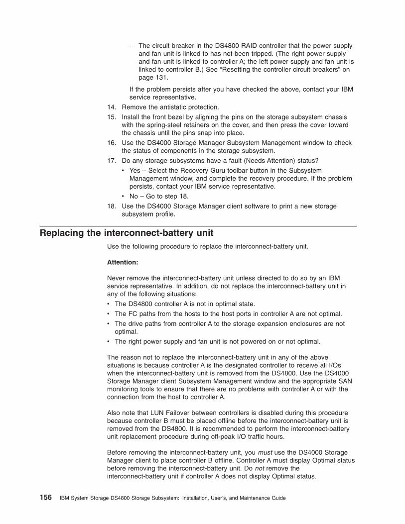
– The circuit breaker in the DS4800 RAID controller that the power supply
and fan unit is linked to has not been tripped. (The right power supply
and fan unit is linked to controller A; the left power supply and fan unit is
linked to controller B.) See “Resetting the controller circuit breakers” on
page 131.
If the problem persists after you have checked the above, contact your IBM
service representative.
14. Remove the antistatic protection.
15. Install the front bezel by aligning the pins on the storage subsystem chassis
with the spring-steel retainers on the cover, and then press the cover toward
the chassis until the pins snap into place.
16. Use the DS4000 Storage Manager Subsystem Management window to check
the status of components in the storage subsystem.
17. Do any storage subsystems have a fault (Needs Attention) status?
v Yes – Select the Recovery Guru toolbar button in the Subsystem
Management window, and complete the recovery procedure. If the problem
persists, contact your IBM service representative.
v No – Go to step 18.
18. Use the DS4000 Storage Manager client software to print a new storage
subsystem profile.
Replacing the interconnect-battery unit
Use the following procedure to replace the interconnect-battery unit.
Attention:
Never remove the interconnect-battery unit unless directed to do so by an IBM
service representative. In addition, do not replace the interconnect-battery unit in
any of the following situations:
v The DS4800 controller A is not in optimal state.
v The FC paths from the hosts to the host ports in controller A are not optimal.
v The drive paths from controller A to the storage expansion enclosures are not
optimal.
v The right power supply and fan unit is not powered on or not optimal.
The reason not to replace the interconnect-battery unit in any of the above
situations is because controller A is the designated controller to receive all I/Os
when the interconnect-battery unit is removed from the DS4800. Use the DS4000
Storage Manager client Subsystem Management window and the appropriate SAN
monitoring tools to ensure that there are no problems with controller A or with the
connection from the host to controller A.
Also note that LUN Failover between controllers is disabled during this procedure
because controller B must be placed offline before the interconnect-battery unit is
removed from the DS4800. It is recommended to perform the interconnect-battery
unit replacement procedure during off-peak I/O traffic hours.
Before removing the interconnect-battery unit, you must use the DS4000 Storage
Manager client to place controller B offline. Controller A must display Optimal status
before removing the interconnect-battery unit. Do not remove the
interconnect-battery unit if controller A does not display Optimal status.
156 IBM System Storage DS4800 Storage Subsystem: Installation, User’s, and Maintenance Guide
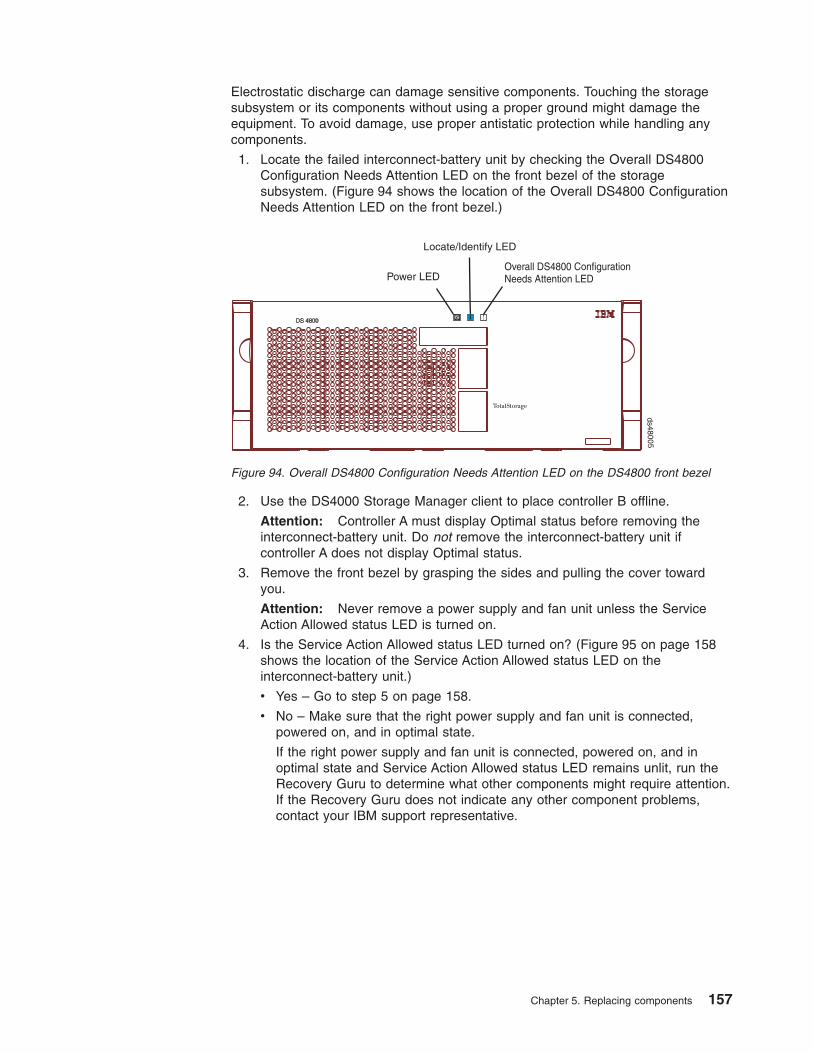
Electrostatic discharge can damage sensitive components. Touching the storage
subsystem or its components without using a proper ground might damage the
equipment. To avoid damage, use proper antistatic protection while handling any
components.
1. Locate the failed interconnect-battery unit by checking the Overall DS4800
Configuration Needs Attention LED on the front bezel of the storage
subsystem. (Figure 94 shows the location of the Overall DS4800 Configuration
Needs Attention LED on the front bezel.)
2. Use the DS4000 Storage Manager client to place controller B offline.
Attention: Controller A must display Optimal status before removing the
interconnect-battery unit. Do not remove the interconnect-battery unit if
controller A does not display Optimal status.
3. Remove the front bezel by grasping the sides and pulling the cover toward
you.
Attention: Never remove a power supply and fan unit unless the Service
Action Allowed status LED is turned on.
4. Is the Service Action Allowed status LED turned on? (Figure 95 on page 158
shows the location of the Service Action Allowed status LED on the
interconnect-battery unit.)
v Yes – Go to step 5 on page 158.
v No – Make sure that the right power supply and fan unit is connected,
powered on, and in optimal state.
If the right power supply and fan unit is connected, powered on, and in
optimal state and Service Action Allowed status LED remains unlit, run the
Recovery Guru to determine what other components might require attention.
If the Recovery Guru does not indicate any other component problems,
contact your IBM support representative.
Power LEDOverall DS4800 ConfigurationNeeds Attention LED
Locate/Identify LED
ds48005
Figure 94. Overall DS4800 Configuration Needs Attention LED on the DS4800 front bezel
Chapter 5. Replacing components 157

5. Put on antistatic protection.
6. Unpack the interconnect-battery unit.
Save all packing materials in the event you need to return the new
interconnect-battery unit.
7. Unlatch both the top and bottom levers of the interconnect-battery unit and
rotate both levers straight out simultaneously to remove the failed
interconnect-battery unit. (Figure 96 on page 159 shows the
interconnect-battery unit sliding from the storage subsystem chassis.)
Service ActionAllowed LED (blue)
ds48049
Overall DS4800 ConfigurationNeeds Attention LED (amber)
Figure 95. Interconnect-battery unit Needs Attention and Service Action Allowed LEDs
158 IBM System Storage DS4800 Storage Subsystem: Installation, User’s, and Maintenance Guide

8. Remove both battery packs from the failed interconnect-battery unit and
replace the battery packs in the replacement interconnect-battery unit. See
“Replacing a backup battery pack” on page 160 for instructions on how to
remove and replace the battery packs from an interconnect-battery unit.
9. Install the new interconnect-battery unit by performing the following steps:
a. Carefully position the interconnect-battery unit in the storage subsystem
chassis.
The interconnect-battery unit has a pin on the connector end of the
component. The pin fits onto a relief cast into the storage subsystem
chassis. (You can see the relief by peering into the slot for the
interconnect-battery unit.) Ensure that the interconnect-battery unit pin is
aligned with the relief in the storage subsystem chassis before attempting
to slide the interconnect-battery unit into the storage subsystem chassis.
b. With the top and bottom levers rotated out perpendicular to the face of the
interconnect-battery unit, slide the back of the unit into the appropriate slot.
c. Holding both levers, slowly push the interconnect-battery unit until the
notches in both the left and right levers are aligned with the pins on the
DS4800 enclosure so that the interconnect-battery unit is pulled evenly into
the DS4800 storage subsystem chassis, ensuring full electrical connection
contact on the interface pin.
Attention: Verify that the interconnect-battery unit does not snag any
other DS4800 cables when you slide it into the bay.
d. Press the interconnect-battery unit fully into the slot, engaging the pins on
the enclosure.
e. Hold open both latches and push both left and right levers simultaneously
to the closed position. Release the latches. When you release the latches,
you should hear both latches snap over the levers, indicating that the
interconnect-battery unit is locked in place.
10. Wait up to 5 minutes for the DS4000 Storage Manager client software to
recognize the new interconnect-battery unit.
Leversin releasedposition
Interconnect-battery unit
ds48017
Figure 96. Removing an interconnect-battery unit from the DS4800
Chapter 5. Replacing components 159

11. Use the DS4000 Storage Manager client to place controller B online.
12. Complete any remaining Recovery Guru procedures for interconnect-battery
unit replacement, if needed.
13. Did this correct the problem?
v Yes – Go to step 14.
v No – If the problem has not been fixed, contact your IBM service
representative.
14. Remove the antistatic protection.
15. Install the front bezel by aligning the pins on the storage subsystem chassis
with the spring-steel retainers on the cover and then press the cover toward
the chassis until the pins snap into place.
16. Use the Subsystem Management window to check the status of all
components in the storage subsystem.
17. Do any storage subsystems have a fault (Needs Attention) status?
v Yes – Select the Recovery Guru toolbar button in the DS4000 Storage
Manager Subsystem Management window, and complete the recovery
procedure. If the problem persists, contact your IBM support representative.
v No – Go to step 18.
18. Use the DS4000 Storage Manager client software to print a new storage
subsystem profile.
Replacing a backup battery pack
Use the following procedure if the DS4000 Storage Manager client instructs you to
replace the battery because the current battery has failed. You can also use the
DS4000 Storage Manager client to check the status of the battery. Because
write-caching is disabled when either one of the backup battery packs fail, IBM
recommends that you replace the failed battery pack as soon as possible to
minimize any impact due to the disabling of the write-caching function.
Replace only the battery pack that is indicated as failed by the LEDs. You do not
need to replace both battery packs when the Battery LEDs indicate that only one
battery pack has failed.
Note: Unlike the batteries for other DS4000 Storage Subsystems, the DS4800
Storage Subsystem battery packs do not have set expiration dates. Do not
replace these batteries after a certain usage period.
Attention: When you handle static-sensitive devices, take precautions to avoid
damage from static electricity. For details about handling static-sensitive devices,
see “Handling static-sensitive devices” on page 141.
Use the following procedure to replace a backup battery pack in the
interconnect-battery unit:
1. Use the DS4000 Storage Manager client software to print a storage subsystem
profile.
2. Locate the storage subsystem that contains the interconnect-battery unit with
the failed battery by checking the Overall DS4800 Configuration Needs
Attention LED on the front bezel of the storage subsystem. (Figure 97 on page
161 shows the location of the Overall DS4800 Configuration Needs Attention
LED on the front bezel.)
160 IBM System Storage DS4800 Storage Subsystem: Installation, User’s, and Maintenance Guide

3. Remove the front bezel by grasping the sides and pulling the cover toward
you.
4. Check the LEDs on the power supply and fan units to determine which of the
two battery packs has failed. (See Figure 84 on page 139.) Replace only the
battery pack that is indicated as failed by the LEDs.
5. Put on antistatic protection.
6. Unpack the new battery pack. Set the new battery pack on a dry, level surface.
Save all packing materials in the event you need to return the new battery
pack.
7. Remove the battery access cover from the front of the interconnect-battery unit
by removing the thumb screws that secure the cover to the component.
Figure 98 shows the access cover and mounting screws on the
interconnect-battery unit.
Power LEDOverall DS4800 ConfigurationNeeds Attention LED
Locate/Identify LED
ds48005
Figure 97. Overall DS4800 Configuration Needs Attention LED on the DS4800 front bezel
Accesscover
Thumbscrews
ds48050
Figure 98. Battery access cover on the interconnect-battery unit
Chapter 5. Replacing components 161

8. Remove the failed battery pack by sliding it out of the interconnect-battery unit.
Note: There are two battery packs in the interconnect-battery unit. The right
and left Battery Needs Attention LEDs on the interconnect-battery unit
correspond to each of the two battery packs. Be sure to remove the
failed battery, as indicated by the lit amber Battery Needs Attention
LED.
The battery pack is mounted to a sheet metal bracket. The sheet metal bracket
has a flange formed on the end of the bracket closest to the access in the
interconnect-battery unit. Grasp the flange to slide the battery pack from the
interconnect-battery unit.
CAUTION:
This product contains a sealed Lithium Ion battery. Discharged Lithium
and Lithium Ion batteries are currently designated to be disposed of in
normal trash. However, users should contact their municipal waste
disposal facility prior to discarding any used battery in normal trash.
Alternatively, IBM recommends users may return Lithium, Lithium Ion
and Lithium Ion battery packs to IBM for recycling.
In the United States, IBM has established a collection process for reuse,
recycling, or proper disposal of used IBM Lithium, Lithium Ion and
Lithium Ion battery packs. For information on proper disposal of these
batteries, please contact IBM at 1-800-426-4333. Please have the IBM part
number listed on the battery available prior to your call.
For information on disposal of sealed Lithium Ion batteries outside the
United States, go to http://www.ibm.com/ibm/environment/products/batteryrecycle.shtml or contact your local waste disposal facility.
9. Install the replacement battery pack. Carefully position the battery pack to
ensure that the battery pack will slide correctly into the interconnect-battery
unit. The flat side of the battery pack should face towards the outside of the
chassis. Make sure that the battery bracket slides properly into the slots for the
battery. Slide the battery pack into the interconnect-battery unit. Push the
battery pack firmly into the interconnect-battery unit to ensure that the battery
pack completely engages with the connectors in the interconnect-battery unit.
10. Reinstall the battery access cover onto the front of the interconnect-battery
unit.
11. Once you have replaced the battery pack, you must reset the battery age
through the DS4000 Storage Manager client, by performing these three steps:
v First, you must select the Controller enclosure components icon in the
Physical View of the Storage Manager client. The Controller enclosure
components dialog will be displayed.
v Next, you must select the Batteries icon, and then select Reset. You will be
asked to Confirm Reset. Select Yes to confirm that you want to reset the
battery age.
162 IBM System Storage DS4800 Storage Subsystem: Installation, User’s, and Maintenance Guide

v Now, the battery age clock is reset to 0.
12. Remove the antistatic protection.
13. Install the front bezel by aligning the pins on the storage subsystem chassis
with the spring-steel retainers on the cover and then press the cover toward
the chassis until the pins snap into place.
14. Use the Subsystem Management window to check the status of all
components in the storage subsystem.
15. Do any storage subsystems have a fault (Needs Attention) status?
v Yes – Select the Recovery Guru toolbar button in the DS4000 Storage
Manager Subsystem Management window, and complete the recovery
procedure. If the problem persists, contact your IBM service representative.
v No – Go to step 16.
16. Use the DS4000 Storage Manager client software to print a new storage
subsystem profile.
Note: Note that it might take from 15 minutes to a few hours for a new battery
to become fully charged. The DS4000 Storage Manager client will show
the battery as charging until it is fully charged. Controller caching is
automatically disabled until the new battery becomes fully charged.
17. After 24 hours, check the Needs Attention and Battery LEDs to ensure that the
battery is working properly.
If the replacement battery indicates a fault, contact your IBM support
representative.
Replacing an SFP module
Use the following procedure to replace an SFP module in a controller. The SFP
module shown in this procedure might look different from those you are using, but
the difference does not affect SFP module performance.
Electrostatic discharge can damage sensitive components. To prevent electrostatic
discharge damage to the storage subsystem, use proper antistatic protection when
handling the DS4800 components.
Attention: Removing an SFP module that has not failed can cause data loss. To
prevent data loss, remove only the SFP module that has a Bypass LED on or that
displays a failed status in the DS4000 Storage Manager client software.
1. Use the DS4000 Storage Manager client software to print a new storage
subsystem profile.
2. Locate the storage subsystem that has the failed SFP module by checking the
Overall DS4800 Configuration Needs Attention LED on the front bezel of the
storage subsystem. (Figure 99 on page 164 shows the location of the Overall
DS4800 Configuration Needs Attention LED on the front bezel.)
Chapter 5. Replacing components 163

3. Locate the failed SFP module by checking the SFP Bypass LED and Needs
Attention LED on the controllers. If a fault is detected, the LEDs are lit.
Figure 100 shows the location of the controller SFP Bypass LED and Needs
Attention LED on the controller.
4. Put on antistatic protection.
5. Unpack the new SFP module. Verify that it is the same type of module you are
replacing. Save all packing materials in the event you might need to return the
new SFP module.
Attention: Handle and install fiber-optic cables properly to avoid degraded
performance or loss of communications with devices. When working with
fiber-optic cables, do not pinch them, step on them, or locate them in aisles or
walkways. Do not overtighten the cable straps or bend the cables to a radius
smaller than 38 mm (1.5 in.).
6. Disconnect the interface cable from the SFP module. (Figure 101 on page 165
shows the SFP module, interface cable, and the rear of a controller.)
Power LEDOverall DS4800 ConfigurationNeeds Attention LED
Locate/Identify LED
ds48005
Figure 99. Overall DS4800 Configuration Needs Attention LED on the DS4800 front bezel
SFP Bypass LEDs
Needs Attention LEDNeeds Attention LED
SFP Bypass LEDs
Controller A
Controller B
ds48051
Figure 100. Needs Attention and SFP Model Bypass LEDs
164 IBM System Storage DS4800 Storage Subsystem: Installation, User’s, and Maintenance Guide

7. Remove the failed SFP module from the controller.
8. Install the new SFP module into the controller.
9. Reconnect the interface cable.
10. Check the Bypass and Needs Attention LEDs for the new SFP module.
Based on the status of the Bypass and Needs Attention LEDs, choose one of
the following steps:
v Bypass LED or Needs Attention LED is illuminated – The SFP module and
cables might be installed incorrectly, or the cable might not be securely
connected. Reinstall the SFP module and cable, check the cable
connection, and then go to step 11.
v Bypass LED and Needs Attention LED are off – Go to step 12.
11. Is the problem corrected?
v Yes – Go to step 12.
v No – Contact your IBM support representative.
12. Remove the antistatic protection.
13. Use the DS4000 Storage Manager Subsystem Management window to check
the status of all components in the storage subsystem.
14. Do any storage subsystems have a Needs Attention (Needs Attention) status?
v Yes – Select the Recovery Guru toolbar button in the Subsystem
Management window and complete the recovery procedure. If the problem
persists, contact your IBM service representative.
v No – Go to step 15.
15. Use the DS4000 Storage Manager client software to print a new storage
subsystem profile.
ds48031
Figure 101. Replacing an SFP module
Chapter 5. Replacing components 165

Installing SFPs and fiber-optic cables
Each RAID controller unit has four single-ported host channels and two dual-ported
drive channels. SFPs are inserted into the ports, and then fibre-channel cables are
connected to the SFPs.
For information on installing SFPs and fiber-optic cables, see “Working with SFPs
and fiber-optic cables” on page 47.
166 IBM System Storage DS4800 Storage Subsystem: Installation, User’s, and Maintenance Guide

Chapter 6. Hardware maintenance
This chapter contains information to help you solve some of the simpler problems
that you might have with your storage subsystem. It contains the problem indicators
and error messages along with suggested actions to take to resolve the problem.
Note: See the IBM System Storage DS4000 Problem Determination Guide for
additional troubleshooting and debugging procedures.
General checkout
Use the status LEDs, Symptom-to-FRU index, and the DS4000 Storage Manager
client software to diagnose problems. See “Solving problems.”
To diagnose a cluster system, use the cluster problem determination procedure in
the IBM System Storage DS4000 Problem Determination Guide.
Note: If power was just applied to the storage subsystem, the green and amber
LEDs might turn on and off intermittently. Wait up to five minutes for the
storage subsystem to finish powering up before you begin to check for faults.
Using the diagnostic hardware
The DS4800 comes with an LC wrap-plug adapter and LC-LC coupler. The
wrap-plug adapter and LC-LC coupler are used to perform the loopback test and to
identify fibre path problems. See the IBM System Storage DS4000 Problem
Determination Guide for more information.
The loopback test and the sendEcho test are described in the IBM System Storage
DS4000 Problem Determination Guide. In the IBM System Storage SAN Integration
Server configuration, a loopback adapter (P/N 17P6918) is included to identify path
problems on the drive loop when using fibre channel 1.2 m copper cable (P/N
18P5237).
Solving problems
Always use the DS4000 Storage Manager client to diagnose storage subsystem
problems and component failures. Also to find solutions to problems that have
definite symptoms.
You can use the symptom-to-FRU index (Table 39 on page 168) as a guide for
troubleshooting problems in addition to the DS4000 Storage Manager Recovery
Guru in the Subsystem Management window. Do not depend solely on Table 39 on
page 168 for FRU replacement decision.
See the problem determination maps in the IBM System Storage DS4000 Problem
Determination Guide for more detailed procedures for problem isolation.
Attention: Do not remove any power supply and fan units, controllers, or
interconnect-battery units from the storage subsystem unless the Service Action
Allowed LED for the component is lit. Always use the appropriate procedure in
Chapter 5, “Replacing components,” on page 141 to prevent an inadvertent
shutdown of the DS4800 as a result of removing the DS4800 components in the
wrong sequence.
© Copyright IBM Corp. 2006, 2007 167

Table 39. DS4800 Symptom-to-FRU index
Problem
indicator Component Possible cause Possible solutions
Amber Needs
Attention LED on
RAID controller
Needs Attention
LED
RAID controller offline If you have placed the controller offline, use the
DS4000 Storage Manager client software to place
it online.
If one controller has been placed offline by the
other controller, contact IBM support. (This is the
case if you use the DS4000 Storage Manager
client software to make repeated attempts to bring
an offline controller online, but the controller keeps
reverting back to an offline state.)
RAID controller failure If the RAID controller Needs Attention LED is on
and the Service Action Allowed LED for that RAID
controller is lit, replace the RAID controller.
If the Service Action Allowed LED for the RAID
controller is not lit, perform additional diagnostics
to identify other component failures. Replace the
other failed components before replacing the
RAID controller.
Drive bypass
LED
Fibre-channel cable is not
attached to the storage
expansion enclosure.
Connect the fibre-channel cable to the enclosure
port; check other connections.
No incoming signal
detected.
Reattach the SFPs and fibre-channel cables.
Verify that the fibre channel cables are in good
condition and that there are no cable management
issues (such as using plastic ties to wrap the
cables or bending the cable loops to less than 1.5
inches).
Verify the SFPs are working properly. Use the
wrap-plug coupler kit that ships with the DS4800
and the wrap-plug instructions in the DS4000
Problem Determination Guide.
Replace input and output SFPs or cables as
necessary.
Amber Needs
Attention LED on
(continued)
Overall DS4800
Configuration
Needs Attention
LED (located on
interconnect-battery unit)
General system error Indicates that a Needs Attention LED somewhere
in the DS4800 storage subsystem configuration,
including all attached storage expansion
enclosures, has turned on. (Check for amber
LEDs on DS4800 components as well as all
attached storage expansion enclosures.) Use the
DS4000 Storage Manager software to diagnose
server problems.
Various DS4800
components
Multiple component failures Do not randomly replace components in the
DS4800. This might result in a subsystem
shutdown, causing a loss of data availability. Use
the DS4000 Storage Manager client program to
identify the failed components. Identify and
replace the failed power supply and fan unit
components first before fixing any other failed
components.
168 IBM System Storage DS4800 Storage Subsystem: Installation, User’s, and Maintenance Guide

Table 39. DS4800 Symptom-to-FRU index (continued)
Problem
indicator Component Possible cause Possible solutions
All green LEDs
off
All CRUs Subsystem power is off. Check that all power cords are plugged in and all
power switches are on. If applicable, check that
the main circuit breakers for the rack cabinet are
turned on.
AC power failure Check the main circuit breaker and AC outlet.
Both power supply and fan
units have failed.
Replace the power supply and fan units.
Both controller circuit
breakers have tripped.
Reset the controller circuit breakers.
Chapter 6. Hardware maintenance 169

Table 39. DS4800 Symptom-to-FRU index (continued)
Problem
indicator Component Possible cause Possible solutions
Amber LED is
on, green LED is
off, blue LED is
off, and Overall
DS4800 Storage
Subsystem
Needs Attention
LED is on
Power supply-fan
v Amber Needs
Attention LED
on
v Blue Service
Action Allowed
LED off
v Green Power
LED off
v Power switch on a power
supply and fan unit is
turned off.
v An electrical outlet circuit
breaker has been tripped.
v There has been an AC
power failure.
v The circuit breaker in the
RAID controller
associated with this PSF
has been tripped.
Check the power supply and fan unit power
switches, circuit breakers, and AC power source.
If none of these sources are the cause of the
fault, then do not replace the failed power supply
and fan unit until you have performed additional
diagnostics to determine why the Service Action
Allowed LED on the power supply and fan unit is
not lit. Call IBM Support if needed.
Interconnect-battery unit
v Amber Battery
Needs
Attention LED
on the
interconnect-battery unit is
on
v Green Battery
LED on the
power supply
and fan unit is
off
Battery failure Verify the failure using DS4000 Storage Manager
Client and replace the failing battery.
Interconnect-battery unit
v Green Power
LED on
interconnect-battery unit is
off
v Amber Battery
Needs
Attention LED
on the
interconnect-battery unit is
on
Interconnect-battery unit
failure or midplane failure
Call IBM support.
RAID controller
v Amber
Controller
Needs
Attention LED
is on.
Controller failure or
controller placed offline
Use DS4000 Storage Manager client software to
place the controller online. It the failure persists,
do not replace the controller unit. Instead, perform
additional diagnostics (such as checking the
power supply and fan unit components) to
determine what additional failures have caused
the associated Service Action Allowed LED on the
controller not to light.
170 IBM System Storage DS4800 Storage Subsystem: Installation, User’s, and Maintenance Guide

Table 39. DS4800 Symptom-to-FRU index (continued)
Problem
indicator Component Possible cause Possible solutions
Amber LED is on
and blue LED is
on, and Overall
DS4800 Storage
Subsystem
Needs Attention
LED is on
Power supply-fan
v Amber Needs
Attention LED
on.
v Blue Service
Action Allowed
LED on.
Power supply-fan failure or
power supply failure
Use DS4000 Storage Manager client software to
verify the failure and replace the power supply
and fan unit.
RAID controller
v Amber
Controller
Needs
Attention LED
is on.
v Blue
Controller
Service Action
Allowed LED
is on.
RAID controller offline If you have placed the controller offline, use the
DS4000 Storage Manager client software to place
it online.
If one controller has been placed offline by the
other controller, contact IBM support. (This is the
case if you use the DS4000 Storage Manager
client software to make repeated attempts to bring
an offline controller online, but the controller keeps
reverting back to an offline state.)
RAID controller failure If the RAID controller Needs Attention LED is on
and the Service Action Allowed LED for that RAID
controller is lit, replace the RAID controller.
If the Service Action Allowed LED for the RAID
controller is not lit, perform additional diagnostics
to identify other component failures. Replace the
other failed components before replacing the
RAID controller.
Interconnect-battery unit
v Amber Needs
Attention LED
is on.
v Blue Service
Action Allowed
LED is on.
Interconnect-battery unit
failure
Contact IBM Support.
Chapter 6. Hardware maintenance 171

Table 39. DS4800 Symptom-to-FRU index (continued)
Problem
indicator Component Possible cause Possible solutions
One or more
Green LEDs off
Controller Cache
LED off
Caching is not enabled or
was disabled because:
v The cache memory in
controllers A and B is
mismatched.
v The battery is charging or
performing a diagnostic
test.
v One of the cache backup
battery packs has failed.
Or, there are no I/Os being
sent to the DS4800.
Enable write-caching using the DS4000 Storage
Manager client program.
Or:
v Use the DS4000 storage manager client
program to verify the cache memory for both
controllers.
v The DS4800 performs battery diagnostic tests
and recharges every 25 hours. Write caching is
disabled during the test and will be enabled
automatically after the test completes. The test
duration time varies depending on the
recharging requirement, but the duration should
be less than 15 minutes.
v Replace the failing battery.
If there are no I/Os being sent to the DS4800,
generate I/Os to send to the DS4800.
Battery LED off
and power
supply and fan
unit Power LED
off
The battery is missing. Verify that the battery is missing. All DS4800s are
shipped with both cache battery packs installed.
Call IBM support if a cache battery pack is
missing and you did not remove any of the cache
battery packs from the DS4800.
L1 and L2 (Link
Speed) LEDs for
a host port
Fibre channel cable is not
attached to the DS4800 host
port or the FC device that
should be connected to this
DS4800 host port.
Connect the fibre channel cable to the enclosure
port; check other connections.
No FC signal detected. Reattach the SFPs and fibre-channel cables.
Verify that the fibre channel cables are in good
condition and that there are no cable management
issues (such as using plastic ties to wrap the
cables or bending the cable loops to less than 1.5
inches).
Verify the SFPs are working properly. Use the
wrap-plug coupler kit that ships with the DS4800
and the wrap-plug instructions in the DS4000
Problem Determination Guide.
Replace input and output SFPs or cables as
necessary.
L1 and L2 (Link
Speed) LEDs of
drive port
SFP module failure or SFP
module not seated properly.
Reseat the SFP.
Verify the SFPs are working properly. Use the
wrap-plug coupler kit that ships with the DS4800
and the wrap-plug instructions in the DS4000
Problem Determination Guide.
Replace SFPs as necessary.
172 IBM System Storage DS4800 Storage Subsystem: Installation, User’s, and Maintenance Guide

Table 39. DS4800 Symptom-to-FRU index (continued)
Problem
indicator Component Possible cause Possible solutions
Only one Blue
Service Action
Allowed LED is
lit with no other
amber Needs
Attention LEDs lit
Interconnect-battery unit
A command from the
DS4800 Subsystem
Management window placed
the interconnect-battery unit
in Identify/Locate mode.
Stop the Identify/Locate action in the DS4800
Subsystem Management window.
Only one Blue
Service Action
Allowed LED is
lit and the amber
Needs Attention
LED for the
same component
is lit
Power
supply-fan,
controller, or
interconnect-battery unit
The component indicated by
both the blue (Service Action
Allowed) LED and the
amber (Needs Attention)
LED has failed and can be
replaced.
Unable to access
drives
Expansion drive
channel
Fibre-channel cabling has
failed.
Ensure that the fibre-channel cables are
undamaged and properly connected.
RAID controller has failed. Replace the RAID controller.
An SFP module has failed. Ensure the SFP module is seated properly;
replace the SFP module.
You have connected more
than eight expansion
enclosures to the ports of
the drive channel. Even
though the drive channel is
dual-ported, the DS4800
currently does not support
more than 112 drives per
drive channel.
Power down the DS4800 and its storage
expansion enclosures. Recable the expansion
enclosures with a maximum of eight expansion
enclosures per drive channel.
Chapter 6. Hardware maintenance 173
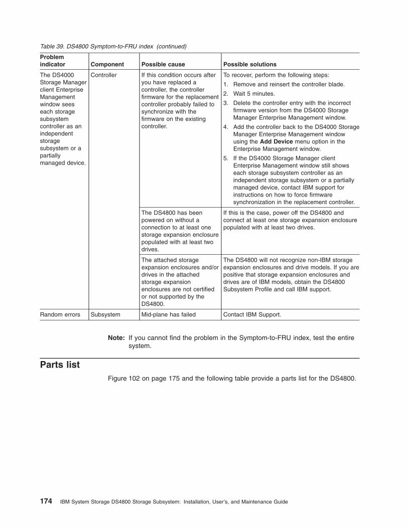
Table 39. DS4800 Symptom-to-FRU index (continued)
Problem
indicator Component Possible cause Possible solutions
The DS4000
Storage Manager
client Enterprise
Management
window sees
each storage
subsystem
controller as an
independent
storage
subsystem or a
partially
managed device.
Controller If this condition occurs after
you have replaced a
controller, the controller
firmware for the replacement
controller probably failed to
synchronize with the
firmware on the existing
controller.
To recover, perform the following steps:
1. Remove and reinsert the controller blade.
2. Wait 5 minutes.
3. Delete the controller entry with the incorrect
firmware version from the DS4000 Storage
Manager Enterprise Management window.
4. Add the controller back to the DS4000 Storage
Manager Enterprise Management window
using the Add Device menu option in the
Enterprise Management window.
5. If the DS4000 Storage Manager client
Enterprise Management window still shows
each storage subsystem controller as an
independent storage subsystem or a partially
managed device, contact IBM support for
instructions on how to force firmware
synchronization in the replacement controller.
The DS4800 has been
powered on without a
connection to at least one
storage expansion enclosure
populated with at least two
drives.
If this is the case, power off the DS4800 and
connect at least one storage expansion enclosure
populated with at least two drives.
The attached storage
expansion enclosures and/or
drives in the attached
storage expansion
enclosures are not certified
or not supported by the
DS4800.
The DS4800 will not recognize non-IBM storage
expansion enclosures and drive models. If you are
positive that storage expansion enclosures and
drives are of IBM models, obtain the DS4800
Subsystem Profile and call IBM support.
Random errors Subsystem Mid-plane has failed Contact IBM Support.
Note: If you cannot find the problem in the Symptom-to-FRU index, test the entire
system.
Parts list
Figure 102 on page 175 and the following table provide a parts list for the DS4800.
174 IBM System Storage DS4800 Storage Subsystem: Installation, User’s, and Maintenance Guide

Table 40. Parts list (System Storage DS4800 Storage Subsystem)
Index DS4800 Storage Subsystem FRU P/N
1 DS4800 bezel assembly 22R4271
2 DS4800 power supply and fan unit 23R1496
3 DS4800 interconnect-battery unit (with plate
and without batteries)
23R0532
4 DS4800 chassis 23R1980 (Model 80H)
23R1982 (Model 80A
Non Korea)
23R1981 (Model 80A
Korea)
22R4272 (Model 82H)
22R4491 (Model 84H)
22R4493 (Model 82A
Non Korea)
22R4494 (Model 82A
Korea)
22R4495 (Model 84H
Non Korea)
22R4496 (Model 84H
Korea)
23R0531 (Model 88H)
23R0529 (Model 88A
Non Korea)
23R0530 (Model 88A
Korea)
1
2
3
6
ds48006
6
5
4
7
Figure 102. DS4800 parts list
Chapter 6. Hardware maintenance 175

Table 40. Parts list (System Storage DS4800 Storage Subsystem) (continued)
Index DS4800 Storage Subsystem FRU P/N
5 DS4800 RAID controller, 2 GB memory, Model
80A/H
23R1983
DS4800 RAID controller, 2 GB memory, Model
82A/H
23R0535
DS4800 RAID controller, 4 GB memory, Model
84A/H
23R0536
DS4800 RAID controller, 8 GB memory, Model
88A/H
23R0537
6 DS4800 mounting rail assembly 22R4839
7 DS4800 battery cover/plate with 4 screws 22R4874
DS4800 battery 22R4875
LC wrap plug assembly 24P0950
LC-SC fibre channel cable adapter 19K1268
Power cord, 2.8–meter (9–ft.) 6952300
Power cord, line jumper, high voltage 36L8886
4–Gbps SFP module 77P2964
Cable, 1–meter fiber-optic 19K1265
Cable, 5–meter fiber-optic 19K1266
Cable, 25–meter fiber-optic 19K1267
176 IBM System Storage DS4800 Storage Subsystem: Installation, User’s, and Maintenance Guide

Appendix A. Additional DS4000 documentation
The following tables present an overview of the IBM System Storage DS4000
Storage Manager, Storage Subsystem, and Storage Expansion Enclosure product
libraries, as well as other related documents. Each table lists documents that are
included in the libraries and what common tasks they address.
You can access the documents listed in these tables at both of the following Web
sites:
www.ibm.com/servers/storage/support/disk/
www.ibm.com/shop/publications/order/
DS4000 Storage Manager Version 9 library
Table 41 associates each document in the DS4000 Storage Manager Version 9
library with its related common user tasks.
Table 41. DS4000 Storage Manager Version 9 titles by user tasks
Title User tasks
Planning Hardware
installation
Software
installation
Configuration Operation and
administration
Diagnosis and
maintenance
IBM System
Storage DS4000
Storage Manager
Version 9
Installation and
Support Guide for
Windows
2000/Server 2003,
NetWare, ESX
Server, and Linux
U U U
IBM System
Storage DS4000
Storage Manager
Version 9
Installation and
Support Guide for
AIX, UNIX, Solaris
and Linux on
POWER
U U U
IBM System
Storage DS4000
Storage Manager
Version 9 Copy
Services User’s
Guide
U U U U
IBM TotalStorage
DS4000 Storage
Manager Version 9
Concepts Guide
U U U U U U
© Copyright IBM Corp. 2006, 2007 177

Table 41. DS4000 Storage Manager Version 9 titles by user tasks (continued)
Title User tasks
Planning Hardware
installation
Software
installation
Configuration Operation and
administration
Diagnosis and
maintenance
IBM System
Storage DS4000
Fibre Channel and
Serial ATA Intermix
Premium Feature
Installation
Overview
U U U U
DS4800 Storage Subsystem library
Table 42 associates each document in the DS4800 Storage Subsystem library with
its related common user tasks.
Table 42. DS4800 Storage Subsystem document titles by user tasks
Title User Tasks
Planning Hardware
Installation
Software
Installation
Configuration Operation and
Administration
Diagnosis and
Maintenance
IBM System Storage
DS4800 Storage
Subsystem
Installation, User’s
and Maintenance
Guide
U U U U U
IBM System Storage
DS4800 Storage
Subsystem
Installation and
Cabling Overview
U
IBM TotalStorage
DS4800 Controller
Cache Upgrade Kit
Instructions
U U U
178 IBM System Storage DS4800 Storage Subsystem: Installation, User’s, and Maintenance Guide

DS4700 Storage Subsystem library
Table 43 associates each document in the DS4700 Storage Subsystem library with
its related common user tasks.
Table 43. DS4700 Storage Subsystem document titles by user tasks
Title User Tasks
Planning Hardware
Installation
Software
Installation
Configuration Operation and
Administration
Diagnosis and
Maintenance
IBM System Storage
DS4700 Storage
Subsystem
Installation, User’s
and Maintenance
Guide
U U U U U
IBM System Storage
DS4700 Storage
Subsystem Fibre
Channel Cabling
Guide
U
Appendix A. Additional DS4000 documentation 179

DS4500 Storage Subsystem library
Table 44 associates each document in the DS4500 (previously FAStT900) Storage
Subsystem library with its related common user tasks.
Table 44. DS4500 Storage Subsystem document titles by user tasks
Title User Tasks
Planning Hardware
Installation
Software
Installation
Configuration Operation and
Administration
Diagnosis and
Maintenance
IBM TotalStorage
DS4500 Storage
Subsystem
Installation, User's,
and Maintenance
Guide
U U U U U
IBM TotalStorage
DS4500 Storage
Subsystem Cabling
Instructions
U U
IBM TotalStorage
DS4500 Rack
Mounting
Instructions
U U
180 IBM System Storage DS4800 Storage Subsystem: Installation, User’s, and Maintenance Guide
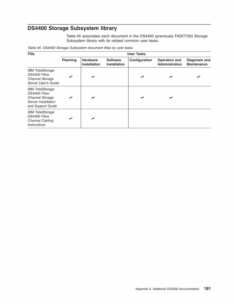
DS4400 Storage Subsystem library
Table 45 associates each document in the DS4400 (previously FAStT700) Storage
Subsystem library with its related common user tasks.
Table 45. DS4400 Storage Subsystem document titles by user tasks
Title User Tasks
Planning Hardware
Installation
Software
Installation
Configuration Operation and
Administration
Diagnosis and
Maintenance
IBM TotalStorage
DS4400 Fibre
Channel Storage
Server User’s Guide
U U U U U
IBM TotalStorage
DS4400 Fibre
Channel Storage
Server Installation
and Support Guide
U U U U
IBM TotalStorage
DS4400 Fibre
Channel Cabling
Instructions
U U
Appendix A. Additional DS4000 documentation 181

DS4300 Storage Subsystem library
Table 46 associates each document in the DS4300 (previously FAStT600) Storage
Subsystem library with its related common user tasks.
Table 46. DS4300 Storage Subsystem document titles by user tasks
Title User Tasks
Planning Hardware
Installation
Software
Installation
Configuration Operation and
Administration
Diagnosis and
Maintenance
IBM TotalStorage
DS4300 Storage
Subsystem
Installation, User’s,
and Maintenance
Guide
U U U U U
IBM TotalStorage
DS4300 Rack
Mounting
Instructions
U U
IBM TotalStorage
DS4300 Storage
Subsystem Cabling
Instructions
U U
IBM TotalStorage
DS4300 SCU Base
Upgrade Kit
U U
IBM TotalStorage
DS4300 SCU Turbo
Upgrade Kit
U U
IBM TotalStorage
DS4300 Turbo
Models 6LU/6LX
Upgrade Kit
U U
182 IBM System Storage DS4800 Storage Subsystem: Installation, User’s, and Maintenance Guide

DS4200 Express Storage Subsystem library
Table 47 associates each document in the DS4200 Express Storage Subsystem
library with its related common user tasks.
Table 47. DS4200 Express Storage Subsystem document titles by user tasks
Title User Tasks
Planning Hardware
Installation
Software
Installation
Configuration Operation and
Administration
Diagnosis and
Maintenance
IBM System Storage
DS4200 Express
Storage Subsystem
Installation, User’s
and Maintenance
Guide
U U U U U
IBM System Storage
DS4200 Express
Storage Subsystem
Cabling Guide
U
Appendix A. Additional DS4000 documentation 183

DS4100 Storage Subsystem library
Table 48 associates each document in the DS4100 (previously FAStT100) Storage
Subsystem library with its related common user tasks.
Table 48. DS4100 Storage Subsystem document titles by user tasks
Title User Tasks
Planning Hardware
Installation
Software
Installation
Configuration Operation and
Administration
Diagnosis and
Maintenance
IBM TotalStorage
DS4100 Storage
Server Installation,
User’s and
Maintenance Guide
U U U U U
IBM TotalStorage
DS4100 Storage
Server Cabling
Guide
U
184 IBM System Storage DS4800 Storage Subsystem: Installation, User’s, and Maintenance Guide

DS4000 Storage Expansion Enclosure documents
Table 49 associates each of the following documents with its related common user
tasks.
Table 49. DS4000 Storage Expansion Enclosure document titles by user tasks
Title User Tasks
Planning Hardware
Installation
Software
Installation
Configuration Operation and
Administration
Diagnosis and
Maintenance
IBM System Storage
DS4000 EXP810
Storage Expansion
Enclosure
Installation, User’s,
and Maintenance
Guide
U U U U U
IBM TotalStorage
DS4000 EXP700
and EXP710
Storage Expansion
Enclosures
Installation, User’s,
and Maintenance
Guide
U U U U U
IBM DS4000
EXP500 Installation
and User’s Guide
U U U U U
IBM System Storage
DS4000 EXP420
Storage Expansion
Enclosure
Installation, User’s,
and Maintenance
Guide
U U U U U
IBM System Storage
DS4000 Hard Drive
and Storage
Expansion
Enclosures
Installation and
Migration Guide
U U
Appendix A. Additional DS4000 documentation 185

Other DS4000 and DS4000-related documents
Table 50 associates each of the following documents with its related common user
tasks.
Table 50. DS4000 and DS4000–related document titles by user tasks
Title User Tasks
Planning Hardware
Installation
Software
Installation
Configuration Operation and
Administration
Diagnosis and
Maintenance
IBM Safety
Information
U
IBM TotalStorage
DS4000 Hardware
Maintenance Manual
¹
U
IBM System Storage
DS4000 Problem
Determination Guide
U
IBM Fibre Channel
Planning and
Integration: User’s
Guide and Service
Information
U U U U
IBM TotalStorage
DS4000 FC2-133
Host Bus Adapter
Installation and
User’s Guide
U U
IBM TotalStorage
DS4000 FC2-133
Dual Port Host Bus
Adapter Installation
and User’s Guide
U U
IBM Netfinity® Fibre
Channel Cabling
Instructions
U
IBM Fibre Channel
SAN Configuration
Setup Guide
U U U U
Notes:
1. The IBM TotalStorage DS4000 Hardware Maintenance Manual does not contain maintenance information for the
IBM System Storage DS4100, DS4200, DS4300, DS4500, DS4700, or DS4800 storage subsystems. You can find
maintenance information for these products in the IBM System Storage DSx000 Storage Subsystem Installation,
User's, and Maintenance Guide for the particular subsystem.
186 IBM System Storage DS4800 Storage Subsystem: Installation, User’s, and Maintenance Guide

Appendix B. Records
Whenever you add options to your DS4800, be sure to update the information in
this appendix. Accurate, up-to-date records make it easier to add other options and
provide needed data whenever you contact your IBM technical support
representative.
Identification numbers
Record and retain the following information. The machine type, model number, and
serial number are located on top of each RAID controller unit. The MAC addresses
are located near the Ethernet ports on each RAID controller, as shown in
Figure 103.
Product name: IBM System Storage DS4800 Storage Subsystem
Machine type: 1815
Model number:
Serial number:
RAID controller MAC addresses:
Controller firmware version:
MAC address label (Controller B)
ds480596 6 6 6 6 6 6 6 6 6 6 6 6 6 6 6 6 6 6 6 6 6 6 6 6 6 6 6 6 6
6 6 6 6 6 6 6 6 6 6 6 6 6 6 6 6 6 6 6 6 6 6 6 6 6 6 6 6 6 66 6 6 6 6 6 6 6 6 6 6 6 6 6 6 6 6 6 6 6 6 6 6 6 6 6 6 6 6 6
666666666666666666666666666666
6 6 6 6 6 6 6 6 6 6 6 6 6 6 6 6 6 6 6 6 6 6 6 6 6 6 6 6 6 6
666666666666666666666666666666
666666666666666666666666666666
666666666666666666666666666666
MAC address label (Controller A)
Figure 103. Location of MAC address labels
© Copyright IBM Corp. 2006, 2007 187

188 IBM System Storage DS4800 Storage Subsystem: Installation, User’s, and Maintenance Guide

Appendix C. Rack mounting templates
This appendix provides duplicate copies of the rack mounting templates. If you want
to tear out the templates from this document for easier use, use these copies rather
than those provided in “Installing the support rails” on page 33.
Use the following templates (Figure 104 on page 190 and Figure 105 on page 191)
to identify the proper locations for inserting M5 screws when mounting the support
rails and DS4800 in a rack cabinet. The locations for the M5 screws are highlighted
in the templates.
The DS4800 is 4 U high. Align the template with the rack at a U boundary. U
boundaries are shown as horizontal dashed lines in the rack mounting templates.
Note: The mounting holes that are shown in the following templates are square.
The holes in your rack cabinet might be round or square.
© Copyright IBM Corp. 2006, 2007 189
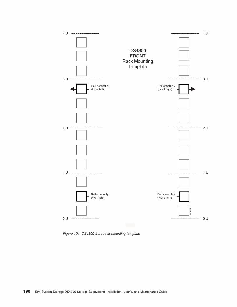
ds48020
DS4800FRONT
Rack MountingTemplate
0 U
2 U
3 U 3 U
2 U
1 U1 U
0 U
4 U4 U
Rail assembly(Front left)
Rail assembly(Front right)
Rail assembly(Front left)
Rail assembly(Front right)
Figure 104. DS4800 front rack mounting template
190 IBM System Storage DS4800 Storage Subsystem: Installation, User’s, and Maintenance Guide

ds48021
DS4800REAR
Rack MountingTemplate
0 U
2 U
3 U 3 U
2 U
1 U1 U
0 U
4 U4 U
Rail assembly(Rear left)
Rail assembly(Rear right)
Printed in the U.S.A
Figure 105. DS4800 rear rack mounting template
Appendix C. Rack mounting templates 191

192 IBM System Storage DS4800 Storage Subsystem: Installation, User’s, and Maintenance Guide

Appendix D. Power cords
For your safety, IBM provides a power cord with a grounded attachment plug to use
with this IBM product. To avoid electrical shock, always use the power cord and
plug with a properly grounded outlet.
IBM power cords used in the United States and Canada are listed by Underwriter’s
Laboratories (UL) and certified by the Canadian Standards Association (CSA).
For units intended to be operated at 115 volts: Use a UL-listed and CSA-certified
cord set consisting of a minimum 18 AWG, Type SVT or SJT, three-conductor cord,
a maximum of 15 feet in length and a parallel blade, grounding-type attachment
plug rated 15 amperes, 125 volts.
For units intended to be operated at 230 volts (U.S. use): Use a UL-listed and
CSA-certified cord set consisting of a minimum 18 AWG, Type SVT or SJT,
three-conductor cord, a maximum of 15 feet in length and a tandem blade,
grounding-type attachment plug rated 15 amperes, 250 volts.
For units intended to be operated at 230 volts (outside the U.S.): Use a cord set
with a grounding-type attachment plug. The cord set should have the appropriate
safety approvals for the country in which the equipment will be installed.
IBM power cords for a specific country or region are usually available only in that
country or region.
IBM power
cord part
number
Cord
specifics Used in these countries or regions
13F9940 250V/10A
2.8M
Australia, Fiji, Kiribati, Nauru, New Zealand, Papua New
Guinea
39Y7917 250V/10A
2.8M
Afghanistan, Albania, Algeria, Andorra, Angola, Armenia,
Austria, Azerbaijan, Belarus, Belgium, Benin, Bosnia and
Herzegovina, Bulgaria, Burkina Faso, Burundi, Cambodia,
Cameroon, Cape Verde, Central African Republic, Chad,
Comoros, Congo (Democratic Republic of), Congo (Republic
of), Cote D’Ivoire (Ivory Coast), Croatia (Republic of), Czech
Rep, Dahomey, Djibouti, Egypt, Equatorial Guinea, Eritrea,
Estonia, Ethiopia, Finland, France, French Guyana, French
Polynesia, Gabon, Georgia, Germany, Greece, Guadeloupe,
Guinea, Guinea Bissau, Hungary, Iceland, Indonesia, Iran,
Kazakhstan, Kyrgyzstan, Laos (Peoples Democratic
Republic of), Latvia, Lebanon, Lithuania, Luxembourg,
Macedonia (former Yugoslav Republic of), Madagascar, Mali,
Martinique, Mauritania, Mauritius, Mayotte, Moldova
(Republic of), Monaco, Mongolia, Morocco, Mozambique,
Netherlands, New Caledonia, Niger, Norway, Poland,
Portugal, Reunion, Romania, Russian Federation Rwanda,
Sao Tome and Principe, Saudi Arabia, Senegal, Serbia,
Slovakia, Slovenia (Republic of), Somalia, Spain, Suriname,
Sweden, Syrian Arab Replublic, Tajikistan, Tahiti, Togo,
Tunisia, Turkey, Turkmenistan, Ukraine, Upper Volta,
Uzbekistan, Vanuatu, Vietnam, Wallis and Futuna,
Yugoslavia (Federal Republic of), Zaire
39Y7918 250V/10A
2.8M
Denmark
© Copyright IBM Corp. 2006, 2007 193

IBM power
cord part
number
Cord
specifics Used in these countries or regions
39Y7922 250V/10A
2.8M
Bangladesh, Lesotho, Macao, Maldives, Namibia, Nepal,
Pakistan, Samoa, South Africa, Sri Lanka, Swaziland,
Uganda
39Y7923 250V/10A
2.8M
Abu Dhabi, Bahrain, Botswana, Brunei Darussalam, Channel
Islands, Cyprus, Dominica, Gambia, Ghana, Grenada,
Guyana, Hong Kong S.A.R. of China, Iraq, Ireland, Jordan,
Kenya, Kuwait, Liberia, Malawi, Malaysia, Malta, Myanmar
(Burma), Nigeria, Oman, Qatar, Saint Kitts & Nevis, Saint
Lucia, Saint Vincent and the Grenadines, Seychelles, Sierra
Leone, Singapore, Sudan, Tanzania (United Republic of),
Trinidad & Tobago, United Arab Emirates (Dubai), United
Kingdom, Yemen, Zambia, Zimbabwe
39Y7919 250V/10A
2.8M
Liechtenstein, Switzerland
39Y7921 250V/10A
2.8M
Chile, Italy, Libyan Arab Jamahiriya
39Y7920 250V/10A
2.8M
Israel
39Y7931 250V/10A
2.8M
Antigua and Barbuda, Aruba, Bahamas, Barbados, Belize,
Bermuda, Bolivia, Brazil, Caicos Islands, Canada, Cayman
Islands, Costa Rica, Columbia, Cuba, Dominican Republic,
Ecuador, El Salvador, Guam, Guatemala, Haiti, Honduras,
Jamaica, Japan, Mexico, Micronesia (Federal States of),
Netherlands Antilles, Nicaragua, Panama, Peru, Philippines,
Taiwan, United States, Venezuela
36L8880 250V/10A
2.8M
Argentina, Paraguay, Uruguay
02K0546 250V/6A
2.8M
PRC (China)
6952300 125V/10A
2.8M
Antigua and Barbuda, Aruba, Bahamas, Barbados, Belize,
Bermuda, Bolivia, Cayman Islands, Costa Rica, Columbia,
Cuba, Dominican Republic, Ecuador, El Salvador, Guam,
Guatemala, Haiti, Honduras, Jamaica, Mexico, Micronesia
(Federal States of), Netherlands Antilles, Nicaragua,
Panama, Peru, Philippines, Saudi Arabia, Taiwan, Thailand,
Turks and Caicos Islands, United States, Venezuela
6952301 125V/10A
1.8M
194 IBM System Storage DS4800 Storage Subsystem: Installation, User’s, and Maintenance Guide

Appendix E. Accessibility
This section provides information about alternate keyboard navigation, which is a
DS4000 Storage Manager accessibility feature. Accessibility features help a user
who has a physical disability, such as restricted mobility or limited vision, to use
software products successfully.
By using the alternate keyboard operations that are described in this section, you
can use keys or key combinations to perform Storage Manager tasks and initiate
many menu actions that can also be done with a mouse.
Note: In addition to the keyboard operations that are described in this section, the
DS4000 Storage Manager version 9.14 - 9.23 (and later) software installation
packages for Windows include a screen reader software interface.
To enable the screen reader, select Custom Installation when using the installation
wizard to install Storage Manager 9.14 - 9.23 (or later) on a Windows
host/management station. Then, in the Select Product Features window, select Java
Access Bridge in addition to the other required host software components.
Table 51 defines the keyboard operations that enable you to navigate, select, or
activate user interface components. The following terms are used in the table:
v Navigate means to move the input focus from one user interface component to
another.
v Select means to choose one or more components, typically for a subsequent
action.
v Activate means to carry out the action of a particular component.
Note: In general, navigation between components requires the following keys:
v Tab - Moves keyboard focus to the next component or to the first member
of the next group of components
v Shift-Tab - Moves keyboard focus to the previous component or to the
first component in the previous group of components
v Arrow keys - Move keyboard focus within the individual components of a
group of components
Table 51. DS4000 Storage Manager alternate keyboard operations
Short cut Action
F1 Open the Help.
F10 Move keyboard focus to main menu bar and post first
menu; use the arrow keys to navigate through the
available options.
Alt+F4 Close the management window.
Alt+F6 Move keyboard focus between dialogs (non-modal) and
between management windows.
© Copyright IBM Corp. 2006, 2007 195

Table 51. DS4000 Storage Manager alternate keyboard operations (continued)
Short cut Action
Alt+ underlined letter Access menu items, buttons, and other interface
components by using the keys associated with the
underlined letters.
For the menu options, select the Alt + underlined letter
combination to access a main menu, and then select the
underlined letter to access the individual menu item.
For other interface components, use the Alt + underlined
letter combination.
Ctrl+F1 Display or conceal a tool tip when keyboard focus is on
the toolbar.
Spacebar Select an item or activate a hyperlink.
Ctrl+Spacebar
(Contiguous/Non-contiguous)
AMW Logical/Physical View
Select multiple drives in the Physical View.
To select multiple drives, select one drive by pressing
Spacebar, and then press Tab to switch focus to the next
drive you want to select; press Ctrl+Spacebar to select
the drive.
If you press Spacebar alone when multiple drives are
selected then all selections are removed.
Use the Ctrl+Spacebar combination to deselect a drive
when multiple drives are selected.
This behavior is the same for contiguous and
non-contiguous selection of drives.
End, Page Down Move keyboard focus to the last item in the list.
Esc Close the current dialog (does not require keyboard
focus).
Home, Page Up Move keyboard focus to the first item in the list.
Shift+Tab Move keyboard focus through components in the reverse
direction.
Ctrl+Tab Move keyboard focus from a table to the next user
interface component.
Tab Navigate keyboard focus between components or select
a hyperlink.
Down arrow Move keyboard focus down one item in the list.
Left arrow Move keyboard focus to the left.
Right arrow Move keyboard focus to the right.
Up arrow Move keyboard focus up one item in the list.
196 IBM System Storage DS4800 Storage Subsystem: Installation, User’s, and Maintenance Guide

Notices
This publication was developed for products and services offered in the U.S.A.
IBM may not offer the products, services, or features discussed in this document in
other countries. Consult your local IBM representative for information on the
products and services currently available in your area. Any reference to an IBM
product, program, or service is not intended to state or imply that only that IBM
product, program, or service may be used. Any functionally equivalent product,
program, or service that does not infringe any IBM intellectual property right may be
used instead. However, it is the user’s responsibility to evaluate and verify the
operation of any non-IBM product, program, or service.
IBM may have patents or pending patent applications covering subject matter
described in this document. The furnishing of this document does not give you any
license to these patents. You can send license inquiries, in writing, to:
IBM Director of Licensing
IBM Corporation
North Castle Drive
Armonk, NY 10504-1785
U.S.A.
INTERNATIONAL BUSINESS MACHINES CORPORATION PROVIDES THIS
PUBLICATION “AS IS” WITHOUT WARRANTY OF ANY KIND, EITHER EXPRESS
OR IMPLIED, INCLUDING, BUT NOT LIMITED TO, THE IMPLIED WARRANTIES
OF NON-INFRINGEMENT, MERCHANTABILITY OR FITNESS FOR A
PARTICULAR PURPOSE. Some jurisdictions do not allow disclaimer of express or
implied warranties in certain transactions, therefore, this statement may not apply to
you.
This information could include technical inaccuracies or typographical errors.
Changes are periodically made to the information herein; these changes will be
incorporated in new editions of the publication. IBM may make improvements and/or
changes in the product(s) and/or the program(s) described in this publication at any
time without notice.
Any references in this publication to non-IBM Web sites are provided for
convenience only and do not in any manner serve as an endorsement of those
Web sites. The materials at those Web sites are not part of the materials for this
IBM product, and use of those Web sites is at your own risk.
IBM may use or distribute any of the information you supply in any way it believes
appropriate without incurring any obligation to you.
Trademarks
The following terms are trademarks of International Business Machines Corporation
in the United States, other countries, or both:
IBM Netfinity
IBM logo PC/XT™
AIX POWER
AT® pSeries®
eServer™ SAA®
© Copyright IBM Corp. 2006, 2007 197

FlashCopy ServerProven®
IBMLink™ System Storage
IntelliStation® xSeries®
XT™
Intel, Pentium, and Intel Xeon are trademarks of Intel Corporation or its subsidiaries
in the United States, other countries, or both.
Java™ and all Java-based trademarks and logos are trademarks or registered
trademarks of Sun Microsystems, Inc. in the United States, other countries, or both.
Microsoft, Windows, Windows NT®, and the Windows logo are trademarks of
Microsoft Corporation in the United States, other countries, or both.
UNIX® is a registered trademark of The Open Group in the United States and other
countries.
Linux is a trademark of Linus Torvalds in the United States, other countries, or both.
Other company, product, or service names may be trademarks or service marks of
others.
Important notes
Processor speeds indicate the internal clock speed of the microprocessor; other
factors also affect application performance.
CD-ROM drive speeds list the variable read rate. Actual speeds vary and are often
less than the maximum possible.
When referring to processor storage, real and virtual storage, or channel volume,
KB stands for approximately 1000 bytes, MB stands for approximately 1 000 000
bytes, and GB stands for approximately 1 000 000 000 bytes.
When referring to hard disk drive capacity or communications volume, MB stands
for 1 000 000 bytes, and GB stands for 1 000 000 000 bytes. Total user-accessible
capacity may vary depending on operating environments.
Maximum internal hard disk drive capacities assume the replacement of any
standard hard disk drives and population of all hard disk drive bays with the largest
currently supported drives available from IBM.
Maximum memory may require replacement of the standard memory with an
optional memory module.
IBM makes no representation or warranties regarding non-IBM products and
services that are ServerProven, including but not limited to the implied warranties of
merchantability and fitness for a particular purpose. These products are offered and
warranted solely by third parties.
IBM makes no representations or warranties with respect to non-IBM products.
Support (if any) for the non-IBM products is provided by the third party, not IBM.
198 IBM System Storage DS4800 Storage Subsystem: Installation, User’s, and Maintenance Guide

Some software may differ from its retail version (if available), and may not include
user manuals or all program functionality.
Product recycling and disposal
This unit contains materials such as circuit boards, cables, electromagnetic
compatibility gaskets, and connectors which may contain lead and copper/beryllium
alloys that require special handling and disposal at end of life. Before this unit is
disposed of, these materials must be removed and recycled or discarded according
to applicable regulations. IBM offers product-return programs in several countries.
Information on product recycling offerings can be found on IBM’s Internet site at
www.ibm.com/ibm/environment/products/prp.shtml.
IBM encourages owners of information technology (IT) equipment to responsibly
recycle their equipment when it is no longer needed. IBM offers a variety of
programs and services to assist equipment owners in recycling their IT products.
Information on product recycling offerings can be found on IBM’s Internet site at
www.ibm.com/ibm/environment/products/prp.shtml.
Notice: This mark applies only to countries within the European Union (EU) and
Norway.
Appliances are labeled in accordance with European Directive 2002/96/EC
concerning waste electrical and electronic equipment (WEEE). The Directive
determines the framework for the return and recycling of used appliances as
applicable throughout the European Union. This label is applied to various products
to indicate that the product is not to be thrown away, but rather reclaimed upon end
of life per this Directive.
Battery return program
This product may contain a sealed lead acid, nickel cadmium, nickel metal hydride,
lithium, or lithium ion battery. Consult your user manual or service manual for
specific battery information. The battery must be recycled or disposed of properly.
Recycling facilities may not be available in your area. For information on disposal of
batteries outside the United States, see http://www.ibm.com/ibm/environment/products/batteryrecycle.shtml or contact your local waste disposal facility.
In the United States, IBM has established a return process for reuse, recycling, or
proper disposal of used IBM sealed lead acid, nickel cadmium, nickel metal hydride,
and battery packs from IBM equipment. For information on proper disposal of these
batteries, contact IBM at 1-800-426-4333. Have the IBM part number listed on the
battery available prior to your call.
In the Netherlands, the following applies.
Notices 199

For Taiwan: Please recycle batteries.
Electronic emission notices
This section gives the electronic emission notices or statements for the United
States and other countries or regions.
Federal Communications Commission (FCC) statement
Note: This equipment has been tested and found to comply with the limits for a
Class A digital device, pursuant to Part 15 of the FCC Rules. These limits are
designed to provide reasonable protection against harmful interference when the
equipment is operated in a commercial environment. This equipment generates,
uses, and can radiate radio frequency energy and, if not installed and used in
accordance with the instruction manual, may cause harmful interference to radio
communications. Operation of this equipment in a residential area is likely to cause
harmful interference, in which case the user will be required to correct the
interference at his own expense.
Properly shielded and grounded cables and connectors must be used in order to
meet FCC emission limits. Properly shielded and grounded cables and connectors
must be used in order to meet FCC emission limits. IBM is not responsible for any
radio or television interference caused by using other than recommended cables
and connectors or by using other than recommended cables and connectors or by
unauthorized changes or modifications to this equipment. Unauthorized changes or
modifications could void the user’s authority to operate the equipment.
This device complies with Part 15 of the FCC Rules. Operation is subject to the
following two conditions: (1) this device may not cause harmful interference, and (2)
this device must accept any interference received, including interference that may
cause undesired operation.
Chinese class A compliance statement
Attention: This is a class A statement. In a domestic environment, this product
might cause radio interference in which case the user might be required to take
adequate measures.
200 IBM System Storage DS4800 Storage Subsystem: Installation, User’s, and Maintenance Guide

Industry Canada Class A emission compliance statement
This Class A digital apparatus complies with Canadian ICES-003.
Avis de conformité à la réglementation d’Industrie Canada
Cet appareil numérique de la classe A est conforme à la norme NMB-003 du
Canada.
Australia and New Zealand Class A statement
Attention: This is a Class A product. In a domestic environment this product may
cause radio interference in which case the user may be required to take adequate
measures.
European Union EMC Directive conformance statement
This product is in conformity with the protection requirements of EU Council
Directive 89/336/EEC on the approximation of the laws of the Member States
relating to electromagnetic compatibility. IBM cannot accept responsibility for any
failure to satisfy the protection requirements resulting from a nonrecommended
modification of the product, including the fitting of non-IBM option cards.
This product has been tested and found to comply with the limits for Class A
Information Technology Equipment according to CISPR 22/European Standard EN
55022. The limits for Class A equipment were derived for commercial and industrial
environments to provide reasonable protection against interference with licensed
communication equipment.
Attention: This is a Class A product. In a domestic environment this product may
cause radio interference in which case the user may be required to take adequate
measures.
Taiwanese Class A warning statement
Notices 201
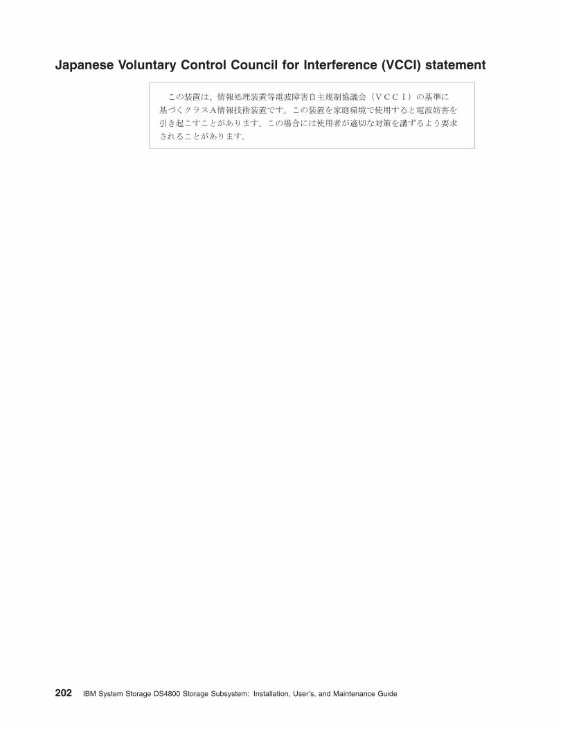
Japanese Voluntary Control Council for Interference (VCCI) statement
202 IBM System Storage DS4800 Storage Subsystem: Installation, User’s, and Maintenance Guide

Glossary
This glossary provides definitions for the
terminology and abbreviations used in IBM
TotalStorage DS4000 publications.
If you do not find the term you are looking for, see
the IBM Glossary of Computing Terms located at
the following Web site:
www.ibm.com/ibm/terminology
This glossary also includes terms and definitions
from:
v Information Technology Vocabulary by
Subcommittee 1, Joint Technical Committee 1,
of the International Organization for
Standardization and the International
Electrotechnical Commission (ISO/IEC
JTC1/SC1). Definitions are identified by the
symbol (I) after the definition; definitions taken
from draft international standards, committee
drafts, and working papers by ISO/IEC
JTC1/SC1 are identified by the symbol (T) after
the definition, indicating that final agreement
has not yet been reached among the
participating National Bodies of SC1.
v IBM Glossary of Computing Terms. New York:
McGraw-Hill, 1994.
The following cross-reference conventions are
used in this glossary:
See Refers you to (a) a term that is the
expanded form of an abbreviation or
acronym, or (b) a synonym or more
preferred term.
See also
Refers you to a related term.
Abstract Windowing Toolkit (AWT). A Java graphical
user interface (GUI).
accelerated graphics port (AGP). A bus specification
that gives low-cost 3D graphics cards faster access to
main memory on personal computers than the usual
peripheral component interconnect (PCI) bus. AGP
reduces the overall cost of creating high-end graphics
subsystems by using existing system memory.
access volume. A special logical drive that allows the
host-agent to communicate with the controllers in the
storage subsystem.
adapter. A printed circuit assembly that transmits user
data input/output (I/O) between the internal bus of the
host system and the external fibre-channel (FC) link and
vice versa. Also called an I/O adapter, host adapter, or
FC adapter.
advanced technology (AT) bus architecture. A bus
standard for IBM compatibles. It extends the XT bus
architecture to 16 bits and also allows for bus
mastering, although only the first 16 MB of main
memory are available for direct access.
agent. A server program that receives virtual
connections from the network manager (the client
program) in a Simple Network Management
Protocol-Transmission Control Protocol/Internet Protocol
(SNMP-TCP/IP) network-managing environment.
AGP. See accelerated graphics port.
AL_PA. See arbitrated loop physical address.
arbitrated loop. One of three existing fibre-channel
topologies, in which 2 - 126 ports are interconnected
serially in a single loop circuit. Access to the Fibre
Channel-Arbitrated Loop (FC-AL) is controlled by an
arbitration scheme. The FC-AL topology supports all
classes of service and guarantees in-order delivery of
FC frames when the originator and responder are on
the same FC-AL. The default topology for the disk array
is arbitrated loop. An arbitrated loop is sometimes
referred to as a Stealth Mode.
arbitrated loop physical address (AL_PA). An 8-bit
value that is used to uniquely identify an individual port
within a loop. A loop can have one or more AL_PAs.
array. A collection of fibre-channel or SATA hard drives
that are logically grouped together. All the drives in the
array are assigned the same RAID level. An array is
sometimes referred to as a ″RAID set.″ See also
redundant array of independent disks (RAID), RAID
level.
asynchronous write mode. In remote mirroring, an
option that allows the primary controller to return a write
I/O request completion to the host server before data
has been successfully written by the secondary
controller. See also synchronous write mode, remote
mirroring, Global Copy,Global Mirroring.
AT. See advanced technology (AT) bus architecture.
ATA. See AT-attached.
AT-attached. Peripheral devices that are compatible
with the original IBM AT computer standard in which
signals on a 40-pin AT-attached (ATA) ribbon cable
followed the timings and constraints of the Industry
Standard Architecture (ISA) system bus on the IBM PC
AT computer. Equivalent to integrated drive electronics
(IDE).
© Copyright IBM Corp. 2006, 2007 203

auto-volume transfer/auto-disk transfer (AVT/ADT).
A function that provides automatic failover in case of
controller failure on a storage subsystem.
AVT/ADT. See auto-volume transfer/auto-disk transfer.
AWT. See Abstract Windowing Toolkit.
basic input/output system (BIOS). The personal
computer code that controls basic hardware operations,
such as interactions with diskette drives, hard disk
drives, and the keyboard.
BIOS. See basic input/output system.
BOOTP. See bootstrap protocol.
bootstrap protocol (BOOTP). In Transmission Control
Protocol/Internet Protocol (TCP/IP) networking, an
alternative protocol by which a diskless machine can
obtain its Internet Protocol (IP) address and such
configuration information as IP addresses of various
servers from a BOOTP server.
bridge. A storage area network (SAN) device that
provides physical and transport conversion, such as
Fibre Channel to small computer system interface
(SCSI) bridge.
bridge group. A bridge and the collection of devices
connected to it.
broadcast. The simultaneous transmission of data to
more than one destination.
cathode ray tube (CRT). A display device in which
controlled electron beams are used to display
alphanumeric or graphical data on an
electroluminescent screen.
client. A computer system or process that requests a
service of another computer system or process that is
typically referred to as a server. Multiple clients can
share access to a common server.
command. A statement used to initiate an action or
start a service. A command consists of the command
name abbreviation, and its parameters and flags if
applicable. A command can be issued by typing it on a
command line or selecting it from a menu.
community string. The name of a community
contained in each Simple Network Management
Protocol (SNMP) message.
concurrent download. A method of downloading and
installing firmware that does not require the user to stop
I/O to the controllers during the process.
CRC. See cyclic redundancy check.
CRT. See cathode ray tube.
CRU. See customer replaceable unit.
customer replaceable unit (CRU). An assembly or
part that a customer can replace in its entirety when any
of its components fail. Contrast with field replaceable
unit (FRU).
cyclic redundancy check (CRC). (1) A redundancy
check in which the check key is generated by a cyclic
algorithm. (2) An error detection technique performed at
both the sending and receiving stations.
dac. See disk array controller.
dar. See disk array router.
DASD. See direct access storage device.
data striping. See striping.
default host group. A logical collection of discovered
host ports, defined host computers, and defined host
groups in the storage-partition topology that fulfill the
following requirements:
v Are not involved in specific logical drive-to-LUN
mappings
v Share access to logical drives with default logical
drive-to-LUN mappings
device type. Identifier used to place devices in the
physical map, such as the switch, hub, or storage.
DHCP. See Dynamic Host Configuration Protocol.
direct access storage device (DASD). A device in
which access time is effectively independent of the
location of the data. Information is entered and retrieved
without reference to previously accessed data. (For
example, a disk drive is a DASD, in contrast with a tape
drive, which stores data as a linear sequence.) DASDs
include both fixed and removable storage devices.
direct memory access (DMA). The transfer of data
between memory and an input/output (I/O) device
without processor intervention.
disk array controller (dac). A disk array controller
device that represents the two controllers of an array.
See also disk array router.
disk array router (dar). A disk array router that
represents an entire array, including current and
deferred paths to all logical unit numbers (LUNs) (hdisks
on AIX). See also disk array controller.
DMA. See direct memory access.
domain. The most significant byte in the node port
(N_port) identifier for the fibre-channel (FC) device. It is
not used in the Fibre Channel-small computer system
interface (FC-SCSI) hardware path ID. It is required to
be the same for all SCSI targets logically connected to
an FC adapter.
204 IBM System Storage DS4800 Storage Subsystem: Installation, User’s, and Maintenance Guide

drive channels. The DS4200, DS4700, and DS4800
subsystems use dual-port drive channels that, from the
physical point of view, are connected in the same way
as two drive loops. However, from the point of view of
the number of drives and enclosures, they are treated
as a single drive loop instead of two different drive
loops. A group of storage expansion enclosures are
connected to the DS4000 storage subsystems using a
drive channel from each controller. This pair of drive
channels is referred to as a redundant drive channel
pair.
drive loops. A drive loop consists of one channel from
each controller combined to form one pair of redundant
drive channels or a redundant drive loop. Each drive
loop is associated with two ports. (There are two drive
channels and four associated ports per controller.) For
the DS4800, drive loops are more commonly referred to
as drive channels. See drive channels.
DRAM. See dynamic random access memory.
Dynamic Host Configuration Protocol (DHCP). A
protocol defined by the Internet Engineering Task Force
that is used for dynamically assigning Internet Protocol
(IP) addresses to computers in a network.
dynamic random access memory (DRAM). A
storage in which the cells require repetitive application
of control signals to retain stored data.
ECC. See error correction coding.
EEPROM. See electrically erasable programmable
read-only memory.
EISA. See Extended Industry Standard Architecture.
electrically erasable programmable read-only
memory (EEPROM). A type of memory chip which can
retain its contents without consistent electrical power.
Unlike the PROM which can be programmed only once,
the EEPROM can be erased electrically. Because it can
only be reprogrammed a limited number of times before
it wears out, it is appropriate for storing small amounts
of data that are changed infrequently.
electrostatic discharge (ESD). The flow of current
that results when objects that have a static charge
come into close enough proximity to discharge.
environmental service module (ESM) canister. A
component in a storage expansion enclosure that
monitors the environmental condition of the components
in that enclosure. Not all storage subsystems have ESM
canisters.
E_port. See expansion port.
error correction coding (ECC). A method for
encoding data so that transmission errors can be
detected and corrected by examining the data on the
receiving end. Most ECCs are characterized by the
maximum number of errors they can detect and correct.
ESD. See electrostatic discharge.
ESM canister. See environmental service module
canister.
automatic ESM firmware synchronization. When
you install a new ESM into an existing storage
expansion enclosure in a DS4000 storage subsystem
that supports automatic ESM firmware synchronization,
the firmware in the new ESM is automatically
synchronized with the firmware in the existing ESM.
EXP. See storage expansion enclosure.
expansion port (E_port). A port that connects the
switches for two fabrics.
Extended Industry Standard Architecture (EISA). A
bus standard for IBM compatibles that extends the
Industry Standard Architecture (ISA) bus architecture to
32 bits and allows more than one central processing
unit (CPU) to share the bus. See also Industry Standard
Architecture.
fabric. A Fibre Channel entity which interconnects and
facilitates logins of N_ports attached to it. The fabric is
responsible for routing frames between source and
destination N_ports using address information in the
frame header. A fabric can be as simple as a
point-to-point channel between two N-ports, or as
complex as a frame-routing switch that provides multiple
and redundant internal pathways within the fabric
between F_ports.
fabric port (F_port). In a fabric, an access point for
connecting a user’s N_port. An F_port facilitates N_port
logins to the fabric from nodes connected to the fabric.
An F_port is addressable by the N_port connected to it.
See also fabric.
FC. See Fibre Channel.
FC-AL. See arbitrated loop.
feature enable identifier. A unique identifier for the
storage subsystem, which is used in the process of
generating a premium feature key. See also premium
feature key.
Fibre Channel (FC). A set of standards for a serial
input/output (I/O) bus capable of transferring data
between two ports at up to 100 Mbps, with standards
proposals to go to higher speeds. FC supports
point-to-point, arbitrated loop, and switched topologies.
Fibre Channel-Arbitrated Loop (FC-AL). See
arbitrated loop.
Fibre Channel Protocol (FCP) for small computer
system interface (SCSI). A high-level fibre-channel
mapping layer (FC-4) that uses lower-level fibre-channel
Glossary 205

(FC-PH) services to transmit SCSI commands, data,
and status information between a SCSI initiator and a
SCSI target across the FC link by using FC frame and
sequence formats.
field replaceable unit (FRU). An assembly that is
replaced in its entirety when any one of its components
fails. In some cases, a field replaceable unit might
contain other field replaceable units. Contrast with
customer replaceable unit (CRU).
FlashCopy. A premium feature for DS4000 that can
make an instantaneous copy of the data in a volume.
F_port. See fabric port.
FRU. See field replaceable unit.
GBIC. See gigabit interface converter
gigabit interface converter (GBIC). A transceiver that
performs serial, optical-to-electrical, and
electrical-to-optical signal conversions for high-speed
networking. A GBIC can be hot swapped. See also
small form-factor pluggable.
Global Copy. Refers to a remote logical drive mirror
pair that is set up using asynchronous write mode
without the write consistency group option. This is also
referred to as ″Asynchronous Mirroring without
Consistency Group.″ Global Copy does not ensure that
write requests to multiple primary logical drives are
carried out in the same order on the secondary logical
drives as they are on the primary logical drives. If it is
critical that writes to the primary logical drives are
carried out in the same order in the appropriate
secondary logical drives, Global Mirroring should be
used instead of Global Copy. See also asynchronous
write mode, Global Mirroring, remote mirroring, Metro
Mirroring.
Global Mirroring. Refers to a remote logical drive
mirror pair that is set up using asynchronous write mode
with the write consistency group option. This is also
referred to as ″Asynchronous Mirroring with Consistency
Group.″ Global Mirroring ensures that write requests to
multiple primary logical drives are carried out in the
same order on the secondary logical drives as they are
on the primary logical drives, preventing data on the
secondary logical drives from becoming inconsistent
with the data on the primary logical drives. See also
asynchronous write mode, Global Copy, remote
mirroring, Metro Mirroring.
graphical user interface (GUI). A type of computer
interface that presents a visual metaphor of a real-world
scene, often of a desktop, by combining high-resolution
graphics, pointing devices, menu bars and other menus,
overlapping windows, icons, and the object-action
relationship.
GUI. See graphical user interface.
HBA. See host bus adapter.
hdisk. An AIX term representing a logical unit number
(LUN) on an array.
heterogeneous host environment. A host system in
which multiple host servers, which use different
operating systems with their own unique disk storage
subsystem settings, connect to the same DS4000
storage subsystem at the same time. See also host.
host. A system that is directly attached to the storage
subsystem through a fibre-channel input/output (I/O)
path. This system is used to serve data (typically in the
form of files) from the storage subsystem. A system can
be both a storage management station and a host
simultaneously.
host bus adapter (HBA). An interface between the
fibre-channel network and a workstation or server.
host computer. See host.
host group. An entity in the storage partition topology
that defines a logical collection of host computers that
require shared access to one or more logical drives.
host port. Ports that physically reside on the host
adapters and are automatically discovered by the
DS4000 Storage Manager software. To give a host
computer access to a partition, its associated host ports
must be defined.
hot swap. To replace a hardware component without
turning off the system.
hub. In a network, a point at which circuits are either
connected or switched. For example, in a star network,
the hub is the central node; in a star/ring network, it is
the location of wiring concentrators.
IBMSAN driver. The device driver that is used in a
Novell NetWare environment to provide multipath
input/output (I/O) support to the storage controller.
IC. See integrated circuit.
IDE. See integrated drive electronics.
in-band. Transmission of management protocol over
the fibre-channel transport.
Industry Standard Architecture (ISA). Unofficial
name for the bus architecture of the IBM PC/XT
personal computer. This bus design included expansion
slots for plugging in various adapter boards. Early
versions had an 8-bit data path, later expanded to 16
bits. The ″Extended Industry Standard Architecture″
(EISA) further expanded the data path to 32 bits. See
also Extended Industry Standard Architecture.
206 IBM System Storage DS4800 Storage Subsystem: Installation, User’s, and Maintenance Guide

initial program load (IPL). The initialization procedure
that causes an operating system to commence
operation. Also referred to as a system restart, system
startup, and boot.
integrated circuit (IC). A microelectronic
semiconductor device that consists of many
interconnected transistors and other components. ICs
are constructed on a small rectangle cut from a silicon
crystal or other semiconductor material. The small size
of these circuits allows high speed, low power
dissipation, and reduced manufacturing cost compared
with board-level integration. Also known as a chip.
integrated drive electronics (IDE). A disk drive
interface based on the 16-bit IBM personal computer
Industry Standard Architecture (ISA) in which the
controller electronics reside on the drive itself,
eliminating the need for a separate adapter card. Also
known as an Advanced Technology Attachment
Interface (ATA).
Internet Protocol (IP). A protocol that routes data
through a network or interconnected networks. IP acts
as an intermediary between the higher protocol layers
and the physical network.
Internet Protocol (IP) address. The unique 32-bit
address that specifies the location of each device or
workstation on the Internet. For example, 9.67.97.103 is
an IP address.
interrupt request (IRQ). A type of input found on
many processors that causes the processor to suspend
normal processing temporarily and start running an
interrupt handler routine. Some processors have several
interrupt request inputs that allow different priority
interrupts.
IP. See Internet Protocol.
IPL. See initial program load.
IRQ. See interrupt request.
ISA. See Industry Standard Architecture.
Java Runtime Environment (JRE). A subset of the
Java Development Kit (JDK) for end users and
developers who want to redistribute the Java Runtime
Environment (JRE). The JRE consists of the Java virtual
machine, the Java Core Classes, and supporting files.
JRE. See Java Runtime Environment.
label. A discovered or user entered property value that
is displayed underneath each device in the Physical and
Data Path maps.
LAN. See local area network.
LBA. See logical block address.
local area network (LAN). A computer network
located on a user’s premises within a limited geographic
area.
logical block address (LBA). The address of a logical
block. Logical block addresses are typically used in
hosts’ I/O commands. The SCSI disk command
protocol, for example, uses logical block addresses.
logical partition (LPAR). (1) A subset of a single
system that contains resources (processors, memory,
and input/output devices). A logical partition operates as
an independent system. If hardware requirements are
met, multiple logical partitions can exist within a system.
(2) A fixed-size portion of a logical volume. A logical
partition is the same size as the physical partitions in its
volume group. Unless the logical volume of which it is a
part is mirrored, each logical partition corresponds to,
and its contents are stored on, a single physical
partition. (3) One to three physical partitions (copies).
The number of logical partitions within a logical volume
is variable.
logical unit number (LUN). An identifier used on a
small computer system interface (SCSI) bus to
distinguish among up to eight devices (logical units) with
the same SCSI ID.
loop address. The unique ID of a node in
fibre-channel loop topology sometimes referred to as a
loop ID.
loop group. A collection of storage area network
(SAN) devices that are interconnected serially in a
single loop circuit.
loop port. A node port (N_port) or fabric port (F_port)
that supports arbitrated loop functions associated with
an arbitrated loop topology.
LPAR. See logical partition.
LUN. See logical unit number.
MAC. See medium access control.
management information base (MIB). The
information that is on an agent. It is an abstraction of
configuration and status information.
man pages. In UNIX-based operating systems, online
documentation for operating system commands,
subroutines, system calls, file formats, special files,
stand-alone utilities, and miscellaneous facilities.
Invoked by the man command.
MCA. See micro channel architecture.
media scan. A media scan is a background process
that runs on all logical drives in the storage subsystem
for which it has been enabled, providing error detection
on the drive media. The media scan process scans all
Glossary 207

logical drive data to verify that it can be accessed, and
optionally scans the logical drive redundancy
information.
medium access control (MAC). In local area
networks (LANs), the sublayer of the data link control
layer that supports medium-dependent functions and
uses the services of the physical layer to provide
services to the logical link control sublayer. The MAC
sublayer includes the method of determining when a
device has access to the transmission medium.
Metro Mirroring. This term is used to refer to a
remote logical drive mirror pair which is set up with
synchronous write mode. See also remote mirroring,
Global Mirroring.
MIB. See management information base.
micro channel architecture (MCA). Hardware that is
used for PS/2 Model 50 computers and above to
provide better growth potential and performance
characteristics when compared with the original
personal computer design.
Microsoft Cluster Server (MSCS). MSCS, a feature
of Windows NT Server (Enterprise Edition), supports the
connection of two servers into a cluster for higher
availability and easier manageability. MSCS can
automatically detect and recover from server or
application failures. It can also be used to balance
server workload and provide for planned maintenance.
mini hub. An interface card or port device that
receives short-wave fiber channel GBICs or SFPs.
These devices enable redundant Fibre Channel
connections from the host computers, either directly or
through a Fibre Channel switch or managed hub, over
optical fiber cables to the DS4000 Storage Server
controllers. Each DS4000 controller is responsible for
two mini hubs. Each mini hub has two ports. Four host
ports (two on each controller) provide a cluster solution
without use of a switch. Two host-side mini hubs are
shipped as standard. See also host port, gigabit
interface converter (GBIC), small form-factor pluggable
(SFP).
mirroring. A fault-tolerance technique in which
information on a hard disk is duplicated on additional
hard disks. See also remote mirroring.
model. The model identification that is assigned to a
device by its manufacturer.
MSCS. See Microsoft Cluster Server.
network management station (NMS). In the Simple
Network Management Protocol (SNMP), a station that
runs management application programs that monitor
and control network elements.
NMI. See non-maskable interrupt.
NMS. See network management station.
non-maskable interrupt (NMI). A hardware interrupt
that another service request cannot overrule (mask). An
NMI bypasses and takes priority over interrupt requests
generated by software, the keyboard, and other such
devices and is issued to the microprocessor only in
disastrous circumstances, such as severe memory
errors or impending power failures.
node. A physical device that allows for the
transmission of data within a network.
node port (N_port). A fibre-channel defined hardware
entity that performs data communications over the
fibre-channel link. It is identifiable by a unique worldwide
name. It can act as an originator or a responder.
nonvolatile storage (NVS). A storage device whose
contents are not lost when power is cut off.
N_port. See node port.
NVS. See nonvolatile storage.
NVSRAM. Nonvolatile storage random access
memory. See nonvolatile storage.
Object Data Manager (ODM). An AIX proprietary
storage mechanism for ASCII stanza files that are
edited as part of configuring a drive into the kernel.
ODM. See Object Data Manager.
out-of-band. Transmission of management protocols
outside of the fibre-channel network, typically over
Ethernet.
partitioning. See storage partition.
parity check. (1) A test to determine whether the
number of ones (or zeros) in an array of binary digits is
odd or even. (2) A mathematical operation on the
numerical representation of the information
communicated between two pieces. For example, if
parity is odd, any character represented by an even
number has a bit added to it, making it odd, and an
information receiver checks that each unit of information
has an odd value.
PCI local bus. See peripheral component interconnect
local bus.
PDF. See portable document format.
performance events. Events related to thresholds set
on storage area network (SAN) performance.
peripheral component interconnect local bus (PCI
local bus). A local bus for PCs, from Intel, that
provides a high-speed data path between the CPU and
up to 10 peripherals (video, disk, network, and so on).
The PCI bus coexists in the PC with the Industry
Standard Architecture (ISA) or Extended Industry
208 IBM System Storage DS4800 Storage Subsystem: Installation, User’s, and Maintenance Guide

Standard Architecture (EISA) bus. ISA and EISA boards
plug into an IA or EISA slot, while high-speed PCI
controllers plug into a PCI slot. See also Industry
Standard Architecture, Extended Industry Standard
Architecture.
polling delay. The time in seconds between
successive discovery processes during which discovery
is inactive.
port. A part of the system unit or remote controller to
which cables for external devices (such as display
stations, terminals, printers, switches, or external
storage units) are attached. The port is an access point
for data entry or exit. A device can contain one or more
ports.
portable document format (PDF). A standard
specified by Adobe Systems, Incorporated, for the
electronic distribution of documents. PDF files are
compact; can be distributed globally by e-mail, the Web,
intranets, or CD-ROM; and can be viewed with the
Acrobat Reader, which is software from Adobe Systems
that can be downloaded at no cost from the Adobe
Systems home page.
premium feature key. A file that the storage
subsystem controller uses to enable an authorized
premium feature. The file contains the feature enable
identifier of the storage subsystem for which the
premium feature is authorized, and data about the
premium feature. See also feature enable identifier.
private loop. A freestanding arbitrated loop with no
fabric attachment. See also arbitrated loop.
program temporary fix (PTF). A temporary solution or
bypass of a problem diagnosed by IBM in a current
unaltered release of the program.
PTF. See program temporary fix.
RAID. See redundant array of independent disks
(RAID).
RAID level. An array’s RAID level is a number that
refers to the method used to achieve redundancy and
fault tolerance in the array. See also array, redundant
array of independent disks (RAID).
RAID set. See array.
RAM. See random-access memory.
random-access memory (RAM). A temporary storage
location in which the central processing unit (CPU)
stores and executes its processes. Contrast with DASD.
RDAC. See redundant disk array controller.
read-only memory (ROM). Memory in which stored
data cannot be changed by the user except under
special conditions.
recoverable virtual shared disk (RVSD). A virtual
shared disk on a server node configured to provide
continuous access to data and file systems in a cluster.
redundant array of independent disks (RAID). A
collection of disk drives (array) that appears as a single
volume to the server, which is fault tolerant through an
assigned method of data striping, mirroring, or parity
checking. Each array is assigned a RAID level, which is
a specific number that refers to the method used to
achieve redundancy and fault tolerance. See also array,
parity check, mirroring, RAID level, striping.
redundant disk array controller (RDAC). (1) In
hardware, a redundant set of controllers (either
active/passive or active/active). (2) In software, a layer
that manages the input/output (I/O) through the active
controller during normal operation and transparently
reroutes I/Os to the other controller in the redundant set
if a controller or I/O path fails.
remote mirroring. Online, real-time replication of data
between storage subsystems that are maintained on
separate media. The Enhanced Remote Mirror Option is
a DS4000 premium feature that provides support for
remote mirroring. See also Global Mirroring, Metro
Mirroring.
ROM. See read-only memory.
router. A computer that determines the path of
network traffic flow. The path selection is made from
several paths based on information obtained from
specific protocols, algorithms that attempt to identify the
shortest or best path, and other criteria such as metrics
or protocol-specific destination addresses.
RVSD. See recoverable virtual shared disk.
SAI. See Storage Array Identifier.
SA Identifier. See Storage Array Identifier.
SAN. See storage area network.
SATA. See serial ATA.
scope. Defines a group of controllers by their Internet
Protocol (IP) addresses. A scope must be created and
defined so that dynamic IP addresses can be assigned
to controllers on the network.
SCSI. See small computer system interface.
segmented loop port (SL_port). A port that allows
division of a fibre-channel private loop into multiple
segments. Each segment can pass frames around as
an independent loop and can connect through the fabric
to other segments of the same loop.
sense data. (1) Data sent with a negative response,
indicating the reason for the response. (2) Data
describing an I/O error. Sense data is presented to a
host system in response to a sense request command.
Glossary 209

serial ATA. The standard for a high-speed alternative
to small computer system interface (SCSI) hard drives.
The SATA-1 standard is equivalent in performance to a
10 000 RPM SCSI drive.
serial storage architecture (SSA). An interface
specification from IBM in which devices are arranged in
a ring topology. SSA, which is compatible with small
computer system interface (SCSI) devices, allows
full-duplex packet multiplexed serial data transfers at
rates of 20 Mbps in each direction.
server. A functional hardware and software unit that
delivers shared resources to workstation client units on
a computer network.
server/device events. Events that occur on the server
or a designated device that meet criteria that the user
sets.
SFP. See small form-factor pluggable.
Simple Network Management Protocol (SNMP). In
the Internet suite of protocols, a network management
protocol that is used to monitor routers and attached
networks. SNMP is an application layer protocol.
Information on devices managed is defined and stored
in the application’s Management Information Base
(MIB).
SL_port. See segmented loop port.
SMagent. The DS4000 Storage Manager optional
Java-based host-agent software, which can be used on
Microsoft Windows, Novell NetWare, AIX, HP-UX,
Solaris, and Linux on POWER host systems to manage
storage subsystems through the host fibre-channel
connection.
SMclient. The DS4000 Storage Manager client
software, which is a Java-based graphical user interface
(GUI) that is used to configure, manage, and
troubleshoot storage servers and storage expansion
enclosures in a DS4000 storage subsystem. SMclient
can be used on a host system or on a storage
management station.
SMruntime. A Java compiler for the SMclient.
SMutil. The DS4000 Storage Manager utility software
that is used on Microsoft Windows, AIX, HP-UX, Solaris,
and Linux on POWER host systems to register and map
new logical drives to the operating system. In Microsoft
Windows, it also contains a utility to flush the cached
data of the operating system for a particular drive before
creating a FlashCopy.
small computer system interface (SCSI). A standard
hardware interface that enables a variety of peripheral
devices to communicate with one another.
small form-factor pluggable (SFP). An optical
transceiver that is used to convert signals between
optical fiber cables and switches. An SFP is smaller
than a gigabit interface converter (GBIC). See also
gigabit interface converter.
SNMP. See Simple Network Management Protocol and
SNMPv1.
SNMP trap event. (1) (2) An event notification sent by
the SNMP agent that identifies conditions, such as
thresholds, that exceed a predetermined value. See
also Simple Network Management Protocol.
SNMPv1. The original standard for SNMP is now
referred to as SNMPv1, as opposed to SNMPv2, a
revision of SNMP. See also Simple Network
Management Protocol.
SRAM. See static random access memory.
SSA. See serial storage architecture.
static random access memory (SRAM). Random
access memory based on the logic circuit know as
flip-flop. It is called static because it retains a value as
long as power is supplied, unlike dynamic random
access memory (DRAM), which must be regularly
refreshed. It is however, still volatile, meaning that it can
lose its contents when the power is turned off.
storage area network (SAN). A dedicated storage
network tailored to a specific environment, combining
servers, storage products, networking products,
software, and services. See also fabric.
Storage Array Identifier (SAI or SA Identifier). The
Storage Array Identifier is the identification value used
by the DS4000 Storage Manager host software
(SMClient) to uniquely identify each managed storage
server. The DS4000 Storage Manager SMClient
program maintains Storage Array Identifier records of
previously-discovered storage servers in the host
resident file, which allows it to retain discovery
information in a persistent fashion.
storage expansion enclosure (EXP). A feature that
can be connected to a system unit to provide additional
storage and processing capacity.
storage management station. A system that is used
to manage the storage subsystem. A storage
management station does not need to be attached to
the storage subsystem through the fibre-channel
input/output (I/O) path.
storage partition. Storage subsystem logical drives
that are visible to a host computer or are shared among
host computers that are part of a host group.
storage partition topology. In the DS4000 Storage
Manager client, the Topology view of the Mappings
window displays the default host group, the defined host
group, the host computer, and host-port nodes. The
host port, host computer, and host group topological
210 IBM System Storage DS4800 Storage Subsystem: Installation, User’s, and Maintenance Guide

elements must be defined to grant access to host
computers and host groups using logical drive-to-LUN
mappings.
striping. Splitting data to be written into equal blocks
and writing blocks simultaneously to separate disk
drives. Striping maximizes performance to the disks.
Reading the data back is also scheduled in parallel, with
a block being read concurrently from each disk then
reassembled at the host.
subnet. An interconnected but independent segment
of a network that is identified by its Internet Protocol (IP)
address.
sweep method. A method of sending Simple Network
Management Protocol (SNMP) requests for information
to all the devices on a subnet by sending the request to
every device in the network.
switch. A fibre-channel device that provides full
bandwidth per port and high-speed routing of data by
using link-level addressing.
switch group. A switch and the collection of devices
connected to it that are not in other groups.
switch zoning. See zoning.
synchronous write mode. In remote mirroring, an
option that requires the primary controller to wait for the
acknowledgment of a write operation from the
secondary controller before returning a write I/O request
completion to the host. See also asynchronous write
mode, remote mirroring, Metro Mirroring.
system name. Device name assigned by the vendor’s
third-party software.
TCP. See Transmission Control Protocol.
TCP/IP. See Transmission Control Protocol/Internet
Protocol.
terminate and stay resident program (TSR
program). A program that installs part of itself as an
extension of DOS when it is executed.
topology. The physical or logical arrangement of
devices on a network. The three fibre-channel
topologies are fabric, arbitrated loop, and point-to-point.
The default topology for the disk array is arbitrated loop.
TL_port. See translated loop port.
transceiver. A device that is used to transmit and
receive data. Transceiver is an abbreviation of
transmitter-receiver.
translated loop port (TL_port). A port that connects
to a private loop and allows connectivity between the
private loop devices and off loop devices (devices not
connected to that particular TL_port).
Transmission Control Protocol (TCP). A
communication protocol used in the Internet and in any
network that follows the Internet Engineering Task Force
(IETF) standards for internetwork protocol. TCP
provides a reliable host-to-host protocol between hosts
in packed-switched communication networks and in
interconnected systems of such networks. It uses the
Internet Protocol (IP) as the underlying protocol.
Transmission Control Protocol/Internet Protocol
(TCP/IP). A set of communication protocols that
provide peer-to-peer connectivity functions for both local
and wide-area networks.
trap. In the Simple Network Management Protocol
(SNMP), a message sent by a managed node (agent
function) to a management station to report an
exception condition.
trap recipient. Receiver of a forwarded Simple
Network Management Protocol (SNMP) trap.
Specifically, a trap receiver is defined by an Internet
Protocol (IP) address and port to which traps are sent.
Presumably, the actual recipient is a software
application running at the IP address and listening to
the port.
TSR program. See terminate and stay resident
program.
uninterruptible power supply. A source of power
from a battery that is installed between a computer
system and its power source. The uninterruptible power
supply keeps the system running if a commercial power
failure occurs, until an orderly shutdown of the system
can be performed.
user action events. Actions that the user takes, such
as changes in the storage area network (SAN), changed
settings, and so on.
worldwide port name (WWPN). A unique identifier for
a switch on local and global networks.
worldwide name (WWN). A globally unique 64-bit
identifier assigned to each Fibre Channel port.
WORM. See write-once read-many.
write-once read many (WORM). Any type of storage
medium to which data can be written only a single time,
but can be read from any number of times. After the
data is recorded, it cannot be altered.
WWN. See worldwide name.
zoning. (1) In Fibre Channel environments, the
grouping of multiple ports to form a virtual, private,
storage network. Ports that are members of a zone can
communicate with each other, but are isolated from
ports in other zones. (2) A function that allows
segmentation of nodes by address, name, or physical
port and is provided by fabric switches or hubs.
Glossary 211

212 IBM System Storage DS4800 Storage Subsystem: Installation, User’s, and Maintenance Guide

Index
AAC power recovery 26
acoustical noise emission values 25
address, IBM xxv
airflow 23, 29
alarm 113
altitude ranges 23
area requirements 21
Bbattery
checking status 139
installing 162
LEDs 138
replacing 138
verify battery charge using client software 163
battery packreplacing 160
battery return 199
best practices 6
BOOTP serversample network 14
Ccabling 47, 48
an IBM DS4000 storage expansion enclosure 52
an IBM System Storage DS4800 52
EXP810 to DS4800 84
cabling the storage subsystemconnecting host to RAID controller 87
connecting power cables 96
connecting secondary interface cables 89
maintaining redundancy 96
to storage expansion enclosures 59
cache batterySee battery 138
cache memorycache active LED 137
size of 137
circuit breakersprocedure to reset 132
resetting the controller circuit breakers 131
Class A electronic emission notice 200
cluster support 3, 167
comments about this document, how to send xxv
componentscontrollers 10
interconnect-battery unit 18
overview 7
power supply and fan units 17
releasing levers 38, 144
replacing 141
weights 21
Concepts Guide 177
configuration, installing the storage subsystem 96
configuring storage subsystem 90
connecting to the DS4800different ways to connect four storage expansion
enclosures 68
controller memory 16
controllerscable connections 11
drive channels 12
Ethernet ports 14
host channels 13
overview 10
replacing 145
resetting the circuit breakers 131
serial port 14
upgrade methods 151
upgrade requirements 151
upgrading 150
cooling 29
copper cables 167
Copy Services Guide 177
customer replaceable units (CRUs)attaching the front bezel 46
removing an interconnect-battery unit 41
removing power supply and fan units 41
removing the controllers 42
replacing a backup battery pack 160
replacing an SFP module 163
replacing the controllers 45, 145
replacing the interconnect-battery unit 45, 156
replacing the power supply and fan units 44, 152
upgrading the controllers 150
DDHCP server
sample network 14
diagnostic hardwarewrap-plug 167
diagnostic interface port 89
directout-of-band 91
disposal 199
documentationDS4000 177
DS4000 Storage Manager 177
DS4000-related documents 186
DS4100 SATA Storage Subsystem 184
DS4200 Express Storage Subsystem 183
DS4300 Fibre Channel Storage Subsystem 182
DS4400 Fibre Channel Storage Subsystem 181
DS4500 Storage Subsystem 180
DS4700 Storage Subsystem 179
DS4800 Storage Subsystem 178
Web sites xxiii
documentation inventory 4
drive channel pairsredundant 60
drive channel pairs, defined 59
© Copyright IBM Corp. 2006, 2007 213

drive channel pairs, described 59
drive channels 12
DS4000Hardware Maintenance Manual 186
Problem Determination Guide 186
Storage Expansion Enclosure documentation 185
DS4000 documentation 177
DS4000 storage expansion enclosuresdrive cabling topologies 69
ID settings 86
recommended ID settings 87
DS4000 Storage Managerdiagnose and repair storage-server failures 115
documentation 177
installing Storage Manager client 114
monitoring status through software 115
Predictive Failure Analysis flag 116
related documents 186
DS4000/FAStT product renaming xvii
DS4100Storage Subsystem library 184
DS4200 ExpressStorage Subsystem library 183
DS4300Storage Subsystem library 182
DS4400Storage Subsystem library 181
DS4500Storage Subsystem library 180
DS4700Storage Subsystem library 179
DS4800Storage Subsystem library 178
EEIA 310-D Type A 19-inch rack cabinet 35
electrical requirements 25
electronic emission Class A notice 200
Electronic emission noticesFederal Communications Commission (FCC)
statement 200
emergency shutdownperforming 111
restoring power 111
environmental requirements and specifications 22
Ethernetconnecting to RAID controller 89
Ethernet ports 14
FFAStT/DS4000 product renaming xvii
FCC Class A notice 200
Australia and New Zealand Class A statement 201
Chinese 200
European Union EMC Directive conformance
statement 201
Industry Canada Class A emission compliance
statement 201
FCC Class A notice (continued)Japanese Voluntary Control Council for Interference
(VCCI) statement 202
Taiwanese Class A warning statement 201
features of the storage subsystem 2
fiber-optic cableconnecting 52
handling 48
installing 51
removing 52
working with 47
fiber-optic cablesinstalling 166
fibre channelconnections 92
loop configurations 93
technology 2
fibre channel loop IDmidplane 86
setting 86
fibre-channel cable adapterLC-SC, using the 55
fire suppression xxv
firmware requirementsappropriate host kit for operating system 114
controller firmware versions 114
for EXP810 attachment 114
HBA drivers 114
installing Storage Manager client 114
IP addresses for RAID controllers 114
latest controller firmware 114
Support CD 114
firmware updatesDS4800 models 80, 82, 84, 88 controller firmware
versions 116
save subsystem profile before 116
form, reader comment xxv
GGBIC
removing 52
general checkouthardware maintenance 167
glossary 203
Hhandling static-sensitive devices 29
hardware inventory 3
hardware maintenancegeneral checkout 167
hardware service and support xxv
Health Check process 102
heat dissipation 23
heat output 29
host adapterconnecting to RAID controller 87
host cableslocation of on RAID controller 88
redundant connections 88
214 IBM System Storage DS4800 Storage Subsystem: Installation, User’s, and Maintenance Guide

host channels 13
host software kits 4
host-agentin-band 91
hot-swap procedures 141
how to send your comments xxv
hubSee managed hub 88
IIBM address xxv
IBM Safety Information 186
IBM Storage System DS4800replacing a controller 145
IBM System Storage DS4800audible alarm 113
best practices 6
cabling the 47
cache memory and cache battery 137
checking the LEDs 118
components 7
connecting power cables 96
controllers 10
diagnostic hardware 167
dimensions 21
DS4800 and eight storage expansion enclosures 75
DS4800 and four storage expansion enclosures 73
DS4800 and fourteen storage expansion
enclosures 76
DS4800 and one storage expansion enclosure 70
DS4800 and sixteen EXP710 storage expansion
enclosures 78
DS4800 and two storage expansion enclosures 71
electrical requirements 25
emergency shutdown 111
environmental requirements and specifications 22
features 2
fibre channel connections 92
front bezel 104
front bezel LEDs 118
hardware maintenance 167
heat output, airflow, and cooling 29
identification numbers 187
installation 37
needed tools 31
installation overview 27
installing into a rack cabinet 27
installing SFP modules 48
installing the configuration 96
installing the DS4800 on the support rails 42
installing the support rails 33
interconnect-battery unit 18
interconnect-battery unit LEDs 127
introduction 1
inventory checklist 3
numeric display 123
operating 101
overheated power supply and fan unit recovery 129
parts list 174
power supply and fan unit LEDs 125
IBM System Storage DS4800 (continued)power supply and fan units 17
preparing for installation 30
preparing the rack cabinet 32
RAID controller LEDs 120
records 187
releasing levers 38
removing components before installation 40
replacing components 141
replacing components before installation 44
resetting the controller circuit breakers 131
restoring power after emergency shutdown 111
restoring power after over-temperature
shutdown 111
restoring power after unexpected shutdown 110
SFP modules 20
site preparation 32
solving problems 167
specifications 21
storage expansion enclosure cabling topologies 69
storage subsystem ports and controllers 69
to seven EXP810 and eight EXP710 storage
expansion enclosures 80
to two or more storage expansion enclosures in a
mixed environment 81
troubleshooting 117
turning off 108
turning on 105
unpacking the 31, 36
weight 21
installationinstalling the DS4800 on the support rails 42
into a rack cabinet 27
overview 27
performing 37
preparing for 30
preparing the rack cabinet 32
removing the components 40
replacing the components 44
site preparation 32
rack cabinet 30
support rails 33
interconnect-battery unitbattery packs 138
installing 159
LEDs 20, 127
overview 18
replacing 156
intermixingstorage expansion enclosures in the same drive
loop 10
inventory checklist 3
LLC-LC fibre-channel cable 53
connecting to an SFP module 53
latches and lever 58
overview 52
protective caps 55
release latches 55
Index 215

LC-LC fibre-channel cable (continued)removing 55
removing from adapter 58
LC-SC fibre-channel cable adapterconnecting to a device 56
connecting to an LC-LC fibre-channel cable 57
protective caps 57
removing an LC-LC fibre-channel cable 58
using 55
LEDscache battery 138
diagnostic 123
front bezel 118
interconnect-battery unit 127
power supply and fan unit 125
RAID controller 120
levers and latches 38, 144
line cord jumpers 3
loop configurationsoverview 93
redundant 93
MMAC address, recording 187
managed hubin fibre channel loop configurations 93
using to connect host to RAID controller 88
memory, cachecache active LED 137
size of 137
Migration Guide 177
Nnotes, important 198
notices 197
electronic emission 200
FCC, Class A 200
static-sensitive precautions 141
trademarks 197
used in this book iii
used in this document xxvi
numeric displaydiagnostic codes 124
Oover-temperature condition, shutdown 111
Pparts list
IBM System Storage DS4800 174
power cordsconnecting 96
DS4800 193
power cords and receptacles 26
power off sequence, storage subsystem 108
power on sequence, storage subsystem 105
power redundancy 6, 101
power supply and fan unitif both units shut down, what to do 130
installing 155
LEDs 125
recovery from overheating 129
replacement procedure 153
replacing 152
shutdown recovery 130
power supply and fan unitsoverview 17
Rrack cabinet
EIA 310-D Type A 19 inch 35
rail installation 36
rack mounting templateDS4800 189
rack mounting template for DS4800 33
RAID controllercache battery 138
connecting Ethernet cable to 89
connecting host to 87
connecting RS-232 (serial) cable 89
RAID controllersLEDs 120
reader comment form processing xxv
records, maintaining 187
Recovery Gurucontroller recovery 136
diagnose failed components 107
overheated power supply and fan unit 131
recycling 199
redundant host and drive loops 93
removing componentsfiber-optic cable 52
renaming xvii
replacing a DS4800 controllerchecking online status 149
installing 148
removing SFPs from RAID controller 147
using client software 145
replacing componentsbattery pack 160
controller 145
handling static-sensitive devices 141
hot-swap procedures 141
interconnect-battery unit 156
multiple component failures 143
overview 141
power supply and fan unit 152
procedure 144
releasing levers 144
Service Action Allowed Status LED 142
SFP module 163
single component failures 142
resourcesWeb sites xxiii
restoring powerafter emergency shutdown 111
216 IBM System Storage DS4800 Storage Subsystem: Installation, User’s, and Maintenance Guide

restoring power (continued)after unexpected shutdown 110
RS-232 serial port 14, 89
Ssafety information iii
SATA technology 2
sending your comments to IBM xxv
serial number, recording 187
SFP modules 20
important information 48
installing 49, 166
operating speeds 48
removing 50
replacing 50, 163
working with 47
shock and vibrations requirements 24
shutdown sequence, storage subsystem 108
Simple Network Management Protocol (SNMP)
traps 14
small form-factor pluggable module (SFP)connecting to an LC-LC fibre-channel cable 53
installing and connecting to LC-LC cable 85
port location 84
removing an LC-LC cable 55
SNMP traps 14
software inventory 4
specifications 21
static-sensitive devices, handling 29, 141
storage area network (SAN)technical support Web site xxiv
storage expansion enclosure settings 85, 86
storage expansion enclosurescabling 62
cabling to EXP100 and EXP710 63
cabling to EXP810 64
connecting EXP810 to DS4800 65
connecting to storage subsystem 59
support 3, 10
turning on before storage subsystem 105
storage subsystem configuration, installing 96
storage subsystem management methods 90
storage subsystem profile 6, 101
switchtechnical support Web site xxiv
symptom-to-FRU index 167
Ttasks by document title 177
tasks by documentation title 177
temperature and humidity 22
trademarks 197
troubleshootingIBM System Storage DS4800 117
with Recovery Guru 118
with Storage Manager client software 117
turning off the storage subsystem 108
turning on the storage subsystem 105
checking normal operation 107
turning on the storage subsystem (continued)startup 105
subsystem status 107
UUnited States electronic emission Class A notice 200
United States FCC Class A notice 200
upgrading componentscontrollers 150
WWeb sites
AIX fix delivery center xxiv
DS4000 interoperability matrix xxiii
DS4000 storage subsystems xxiii
DS4000 technical support xxiv
IBM publications center xxiv
IBM System Storage products xxiii
Linux on POWER support xxv
Linux on System p support xxv
list xxiii
premium feature activation xxiv
readme files xxiii
SAN support xxiv
switch support xxiv
wiring and power 26
wrap-plug 4, 167
Index 217

218 IBM System Storage DS4800 Storage Subsystem: Installation, User’s, and Maintenance Guide

Readers’ Comments — We’d Like to Hear from You
IBM System Storage DS4800 Storage Subsystem
Installation, User’s, and Maintenance Guide
Publication No. GC26-7845-01
We appreciate your comments about this publication. Please comment on specific errors or omissions, accuracy,
organization, subject matter, or completeness of this book. The comments you send should pertain to only the
information in this manual or product and the way in which the information is presented.
For technical questions and information about products and prices, please contact your IBM branch office, your IBM
business partner, or your authorized remarketer.
When you send comments to IBM, you grant IBM a nonexclusive right to use or distribute your comments in any
way it believes appropriate without incurring any obligation to you. IBM or any other organizations will only use the
personal information that you supply to contact you about the issues that you state on this form.
Comments:
Thank you for your support.
Submit your comments using one of these channels:
v Send your comments to the address on the reverse side of this form.
If you would like a response from IBM, please fill in the following information:
Name
Address
Company or Organization
Phone No. E-mail address

Readers’ Comments — We’d Like to Hear from You GC26-7845-01
GC26-7845-01
����
Cut or FoldAlong Line
Cut or FoldAlong Line
Fold and Tape Please do not staple Fold and Tape
Fold and Tape Please do not staple Fold and Tape
NO POSTAGENECESSARYIF MAILED IN THEUNITED STATES
BUSINESS REPLY MAIL FIRST-CLASS MAIL PERMIT NO. 40 ARMONK, NEW YORK
POSTAGE WILL BE PAID BY ADDRESSEE
International Business Machines Corporation
Information Development
Dept. GZW
9000 South Rita Road
Tuscon, AZ
U.S.A. 85744-0001
_ _ _ _ _ _ _ _ _ _ _ _ _ _ _ _ _ _ _ _ _ _ _ _ _ _ _ _ _ _ _ _ _ _ _ _ _ _ _ _ _ _ _ _ _ _ _ _ _ _ _ _ _ _ _ _ _ _ _ _ _ _ _ _ _ _ _ _ _ _ _ _ _ _ _ _ _ _ _ _ _ _ _ _ _ _ _ _ _
_ _ _ _ _ _ _ _ _ _ _ _ _ _ _ _ _ _ _ _ _ _ _ _ _ _ _ _ _ _ _ _ _ _ _ _ _ _ _ _ _ _ _ _ _ _ _ _ _ _ _ _ _ _ _ _ _ _ _ _ _ _ _ _ _ _ _ _ _ _ _ _ _ _ _ _ _ _ _ _ _ _ _ _ _ _ _ _ _
__
__
__
__
__
__
__
__
__
__
__
__
__
__
__
__
__
__
__
__
__
__
__
__
__
__
__
__
__
__
__
__
__
__
__
__
__
__
__
__
__
__
__
__
__
__
__
__
__
_


����
Part Number: 22R6614
Printed in USA
GC26-7845-01
(1P)
P/N:
22
R661
4


![Unleashing Linux*-Based Secure Storage ... - intel.com.tw · 1] is a popular cipher for use in secure storage.In Linux*, the storage subsystem leverages the crypto subsystem to access](https://img.pdfslide.net/doc/110x75/5ecbeafbd43cd479d96a08c9/unleashing-linux-based-secure-storage-intelcomtw-1-is-a-popular-cipher.jpg)