Embed Size (px)
Citation preview
March 2005
Lampe, Hach, Menzer, Nanotron; Lee, OrthotronSlide 1
IEEE-15-05-0126-00-004a
Submission
Project: IEEE P802.15 Working Group for Wireless Personal Area Networks (WPANs)Project: IEEE P802.15 Working Group for Wireless Personal Area Networks (WPANs)
Submission Title: DBO-CSS PHY Presentation for 802.15.4aDate Submitted: March 07, 2005Source: [(1) John Lampe, et al, (2) Kyung-Kuk Lee, et al]Company: [(1) Nanotron Technologies, (2) Orthotron Co., Ltd.]Address: [(1) Alt-Moabit 61, 10555 Berlin, Germany, (2) 709 Kranz Techono, 5442-1 Sangdaewon-dong, Jungwon-gu, Sungnam-si, Kyungki-do, Korea 462-120]Voice: [(1) +49 30 399 954 135, (2) 82-31-777-8198 ], E-Mail: [(1) [email protected], (2) [email protected]]
Re: This is in response to the TG4a Call for Proposals, 04/0380r2
Abstract: The Nanotron - Orthotron DBO-CSS is described and the detailed response to the Selection Criteria document is provided
Purpose: Submitted as the candidate proposal for TG4a Alt-PHY
Notice: This document has been prepared to assist the IEEE P802.15. It is offered as a basis for discussion and is not binding on the contributing individual(s) or organization(s). The material in this document is subject to change in form and content after further study. The contributor(s) reserve(s) the right to add, amend or withdraw material contained herein.Release: The contributor acknowledges and accepts that this contribution becomes the property of IEEE and may be made publicly available by P802.15.
March 2005
Lampe, Hach, Menzer, Nanotron; Lee, OrthotronSlide 2
IEEE-15-05-0126-00-004a
Submission
Differentially Bi-OrthogonalDifferentially Bi-OrthogonalChirp-Spread-SpectrumChirp-Spread-Spectrum
PHY Proposal for 802.15.4aPHY Proposal for 802.15.4aby
John Lampe, Rainer Hach, and Lars Menzer Nanotron Technologies GmbH, Germany
Kyung-Kuk Lee / Jong-Wha ChongOrthotron Co., Ltd. / Hanyang Univ., Korea
March 2005
Lampe, Hach, Menzer, Nanotron; Lee, OrthotronSlide 3
IEEE-15-05-0126-00-004a
Submission
Contents
■ DBO-CSS System Overview
■ Selection Criteria Document Topics
■ PAR and 5C Requirement Checklist
■ Summary
March 2005
Lampe, Hach, Menzer, Nanotron; Lee, OrthotronSlide 4
IEEE-15-05-0126-00-004a
Submission
DBO-CSS System Overview■ Chirp Property■ Concept of Sub-Chirps■ Block-diagram
♣ DBO-CSK: Differentially Bi-Orthogonal Chirp-Spread-Spectrum
March 2005
Lampe, Hach, Menzer, Nanotron; Lee, OrthotronSlide 5
IEEE-15-05-0126-00-004a
Submission
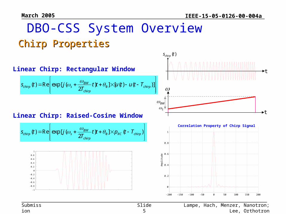
0( ) Re exp[ ( ) ] [ ( ) ( )]2
BWchirp s chirp
chirp
s t j t t u t u t TT
SBW
t
t
( )chirps t
0( ) Re exp[ ( ) ] ( )2
BWchirp s RC chirp
chirp
s t j t t p t TT
Linear Chirp: Rectangular Window
Linear Chirp: Raised-Cosine Window
-1
-0.8
-0.6
-0.4
-0.2
0
0.2
0.4
0.6
0.8
1
-200 -150 -100 -50 0 50 100 150 200
0
0.2
0.4
0.6
0.8
1
Correlation Property of Chirp Signal
Am
plitu
de
DBO-CSS System OverviewChirp PropertiesChirp Properties
March 2005
Lampe, Hach, Menzer, Nanotron; Lee, OrthotronSlide 6
IEEE-15-05-0126-00-004a
Submission
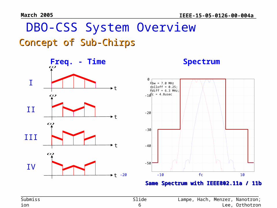
-20 -10 fc 10 20 (MHz)
-50
-40
-30
-20
-10
0
Spectrum
Fbw = 7.0 MHzrolloff = 0.25;Fdiff = 6.3 MHz;Tc = 4.8usec
Same Spectrum with IEEE802.11a / 11bSame Spectrum with IEEE802.11a / 11b
I
II
III
IV
Freq. - Time
t
t
t
t
DBO-CSS System OverviewConcept of Sub-ChirpsConcept of Sub-Chirps
March 2005
Lampe, Hach, Menzer, Nanotron; Lee, OrthotronSlide 7
IEEE-15-05-0126-00-004a
Submission
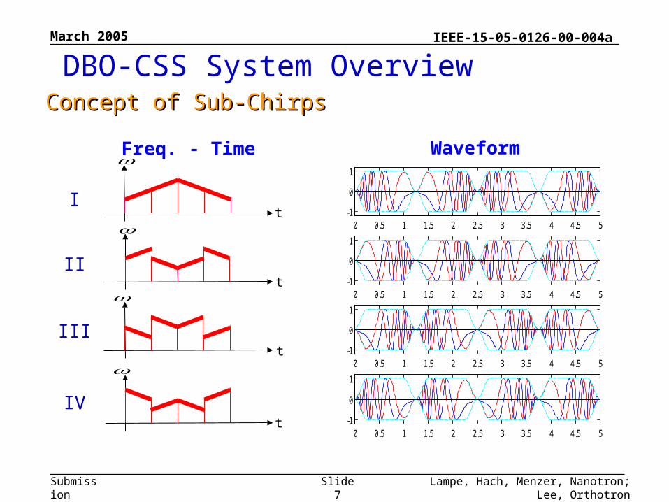
Waveform
0 0.5 1 1.5 2 2.5 3 3.5 4 4.5 5-1
0
1
0 0.5 1 1.5 2 2.5 3 3.5 4 4.5 5-1
0
1
0 0.5 1 1.5 2 2.5 3 3.5 4 4.5 5-1
0
1
0 0.5 1 1.5 2 2.5 3 3.5 4 4.5 5-1
0
1
I
II
III
IV
Freq. - Time
t
t
t
t
DBO-CSS System OverviewConcept of Sub-ChirpsConcept of Sub-Chirps
March 2005
Lampe, Hach, Menzer, Nanotron; Lee, OrthotronSlide 8
IEEE-15-05-0126-00-004a
Submission
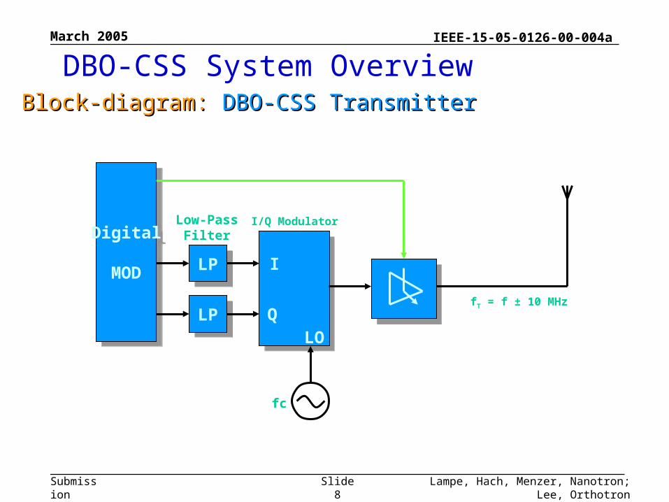
Digital
MOD
Digital
MOD LPLP
LPLP
I
QLO
fc
I/Q Modulator
fT = f ± 10 MHz
Low-PassFilter
Block-diagram: Block-diagram: DBO-CSSDBO-CSS TransmitterTransmitter
DBO-CSS System Overview
March 2005
Lampe, Hach, Menzer, Nanotron; Lee, OrthotronSlide 9
IEEE-15-05-0126-00-004a
Submission
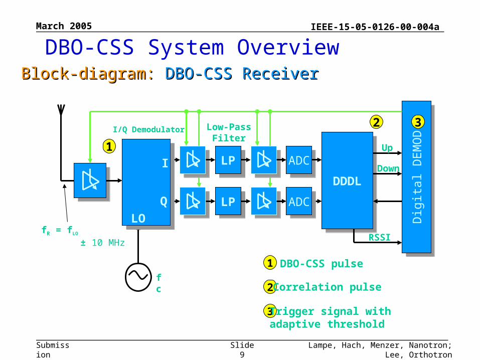
DDDLDDDL
Dig
ital D
EM
OD
Dig
ital D
EM
OD
fR = fLO
± 10 MHz
Up
Down
RSSI
I/Q Demodulator
I
QLO
LPLP
LPLP
Low-PassFilter
ADCADC
fc
1
1 DBO-CSS pulse
2
2Correlation pulse
3Trigger signal with adaptive threshold
3
ADCADC
Block-diagram: Block-diagram: DBO-CSSDBO-CSS ReceiverReceiver
DBO-CSS System Overview
March 2005
Lampe, Hach, Menzer, Nanotron; Lee, OrthotronSlide 10
IEEE-15-05-0126-00-004a
Submission
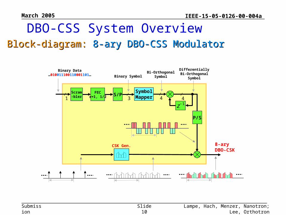
DBO-CSS System OverviewBlock-diagram: Block-diagram: 8-ary DBO-CSS8-ary DBO-CSS ModulatorModulator
1z
CSK Gen.
1 3 4 4
P/S
8-aryDBO-CSK
SymbolMapperS/PFEC
r=1, 1/2Scram-bler
Binary Data…010011100110001101… Binary Symbol
Bi-OrthogonalSymbol
DifferentiallyBi-Orthogonal
Symbol
March 2005
Lampe, Hach, Menzer, Nanotron; Lee, OrthotronSlide 11
IEEE-15-05-0126-00-004a
Submission
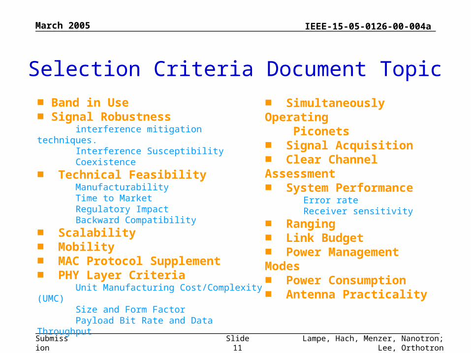
■ Band in Use■ Signal Robustness interference mitigation techniques. Interference Susceptibility Coexistence
■ Technical Feasibility Manufacturability Time to Market Regulatory Impact Backward Compatibility
■ Scalability■ Mobility ■ MAC Protocol Supplement■ PHY Layer Criteria Unit Manufacturing Cost/Complexity (UMC) Size and Form Factor Payload Bit Rate and Data Throughput
■ Simultaneously Operating Piconets■ Signal Acquisition■ Clear Channel Assessment■ System Performance Error rate Receiver sensitivity
■ Ranging■ Link Budget■ Power Management Modes■ Power Consumption■ Antenna Practicality
Selection Criteria Document Topic
March 2005
Lampe, Hach, Menzer, Nanotron; Lee, OrthotronSlide 12
IEEE-15-05-0126-00-004a
Submission
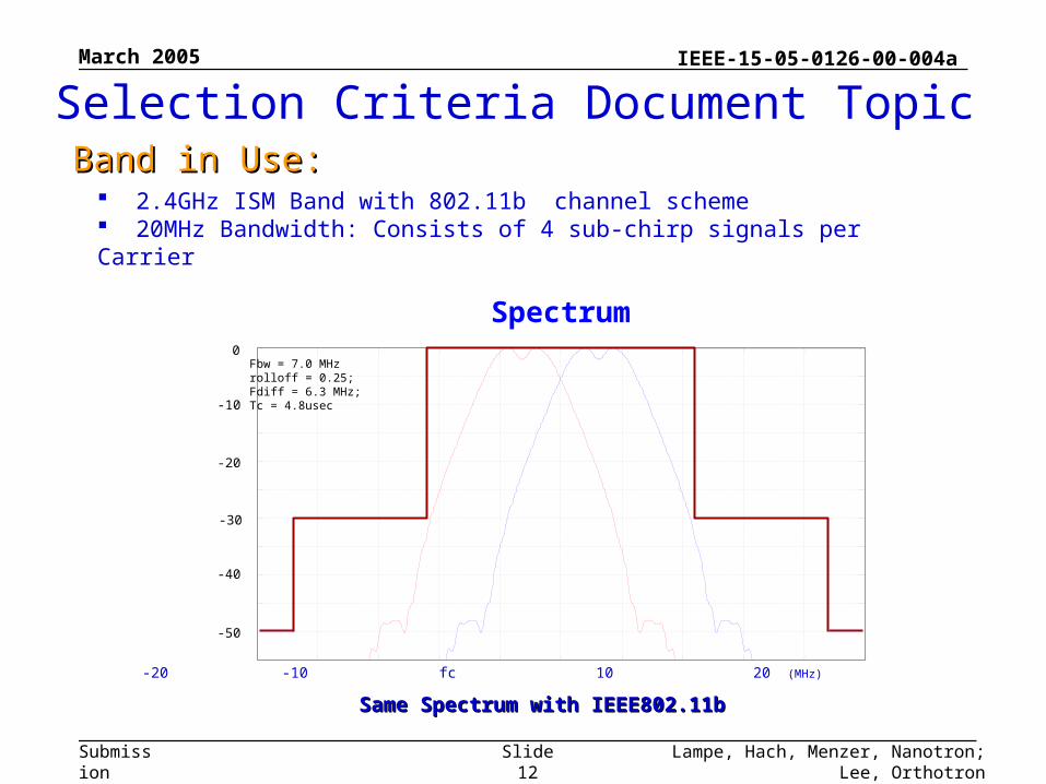
2.4GHz ISM Band with 802.11b channel scheme 20MHz Bandwidth: Consists of 4 sub-chirp signals per Carrier
Selection Criteria Document TopicBand in Use:Band in Use:
-20 -10 fc 10 20 (MHz)
-50
-40
-30
-20
-10
0
Spectrum
Fbw = 7.0 MHzrolloff = 0.25;Fdiff = 6.3 MHz;Tc = 4.8usec
Same Spectrum with IEEE802.11bSame Spectrum with IEEE802.11b
March 2005
Lampe, Hach, Menzer, Nanotron; Lee, OrthotronSlide 13
IEEE-15-05-0126-00-004a
Submission
■ Co-existence / Interference Mitigation Technique - Orthogonal / Quasi-Orthogonal Signal Set - High Spectral Processing Gain: Chirp - Near-Far Problem: FDM Channels (7ch @2.4GHz)
■ Interference Susceptibility - Low Cross-Correlation property with Existing Signal
■ Robustness: - Heavy Multi-path Environment - SOP
■ Low Sensitivity for Component Tolerance - Crystal : ± 40ppm
■ Mobility - Wide-band Chirp: Insensitive for Fading & Doppler Shift - Easily Maintaining Timing Sync. of Received Signal
Selection Criteria Document TopicSignal Robustness:Signal Robustness:
March 2005
Lampe, Hach, Menzer, Nanotron; Lee, OrthotronSlide 14
IEEE-15-05-0126-00-004a
Submission
Selection Criteria Document TopicSignal Robustness: Signal Robustness: Interference Mitigation Techniques The proposed DBO-CSS PHY is designed to operate in a hostile
environment – Multipath– Narrow and broadband intentional and unintentional interferers
Since a chirp transverses a relatively wide bandwidth it has an inherent immunity to narrow band interferers
Multipath is mitigated with the natural frequency diversity of the waveform Broadband interferer effects are reduced by the receiver’s correlator Forward Error Correction (FEC) can further reduce interference and
multipath effects. Three non-overlapping frequency channels in the 2.4 GHz ISM band
– This channelization allows this proposal to coexist with other wireless systems such as 802.11 b, g and even Bluetooth (v1.2 has adaptive hopping) via DFS
DBO-CSS proposal utilizes CCA mechanisms of Energy Detection (ED) and Carrier Detection
These CCA mechanisms are similar to those used in IEEE 802.15.4-2003– In addition to the low duty cycle for the applications served by this standard
sufficient arguments were made to convince the IEEE 802 sponsor ballot community that coexistence was not an issue.
March 2005
Lampe, Hach, Menzer, Nanotron; Lee, OrthotronSlide 15
IEEE-15-05-0126-00-004a
Submission
Selection Criteria Document TopicSignal Robustness: Signal Robustness: Interference Susceptibility
Support for Interference Ingress Example (without FEC):
– Bandwidth B of the chirp = 20 MHz
– Duration time T of the chirp = 4.8 µs
– Center frequency of the chirp (ISM band) = 2.437 GHz
– Processing gain, BT product of the chirp = 19.8 dB
– Eb/N0 at detector input (BER=10E-4) = 12.5 dB
– In-band carrier to interferer ratio (C/I @ BER=10-4)= 12.5 – 19.8 = -7.3 dB
March 2005
Lampe, Hach, Menzer, Nanotron; Lee, OrthotronSlide 16
IEEE-15-05-0126-00-004a
Submission
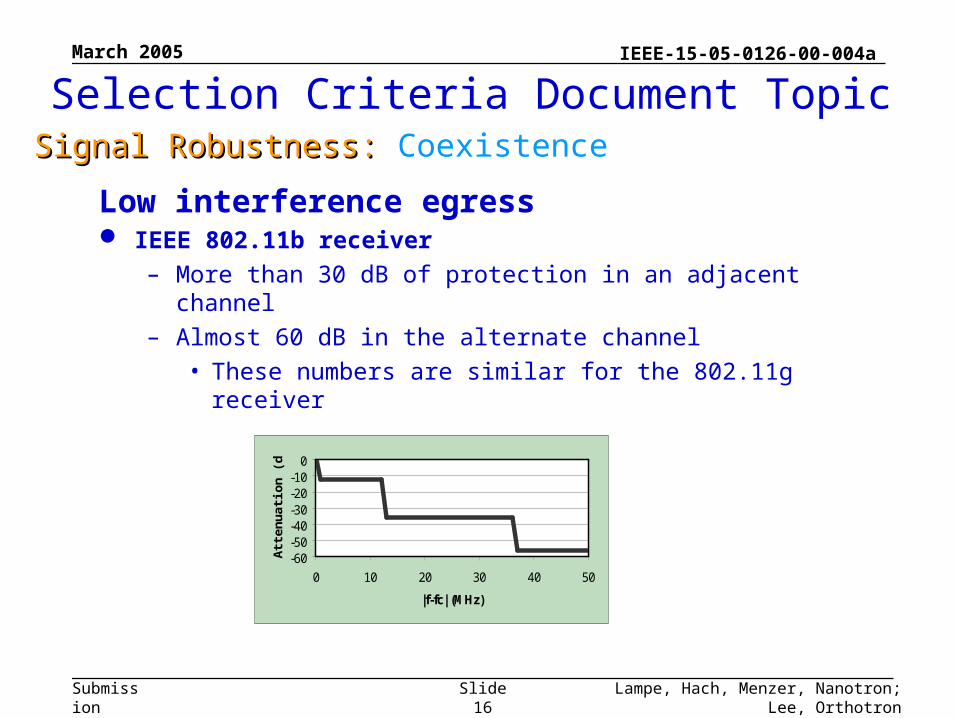
Selection Criteria Document TopicSignal Robustness: Signal Robustness: Coexistence
-60-50-40-30-20-10
0
0 10 20 30 40 50
|f-fc| (MHz)
Att
enu
atio
n (
dB
)
Low interference egress IEEE 802.11b receiver
– More than 30 dB of protection in an adjacent channel
– Almost 60 dB in the alternate channel
• These numbers are similar for the 802.11g receiver
March 2005
Lampe, Hach, Menzer, Nanotron; Lee, OrthotronSlide 17
IEEE-15-05-0126-00-004a
Submission
Selection Criteria Document TopicTechnical Feasibility: Technical Feasibility: Manufacturability
March 2005
Lampe, Hach, Menzer, Nanotron; Lee, OrthotronSlide 18
IEEE-15-05-0126-00-004a
Submission
Selection Criteria Document TopicTechnical Feasibility: Technical Feasibility: Time to Market
No regulatory hurdles DBO-CSS based chips are available on the market No research barriers – no unknown blocks Normal design and product cycles will apply Can be manufactured in all CMOS

March 2005
Lampe, Hach, Menzer, Nanotron; Lee, OrthotronSlide 19
IEEE-15-05-0126-00-004a
Submission
Selection Criteria Document TopicTechnical Feasibility: Technical Feasibility: Regulatory Impact
Devices manufactured in compliance with the DBO-CSS proposal can be operated under existing regulations in all significant regions of the world- Including but not limited to North and South America, Europe, Japan,
China, Korea, and most other areas- There are no known limitation to this proposal as to indoors or
outdoors The DBO-CSS proposal would adhere to the following
worldwide regulations:- United States Part 15.247 or 15.249- Canada DOC RSS-210- Europe ETS 300-328- Japan ARIB STD T-66
March 2005
Lampe, Hach, Menzer, Nanotron; Lee, OrthotronSlide 20
IEEE-15-05-0126-00-004a
Submission
Selection Criteria Document TopicTechnical Feasibility: Technical Feasibility: Backward Compatibility
Due to the similarities with DSSS it is possible to implement this proposal in a manner that will allow backward-compatibility with the 802.15.4 2.4 GHz standard.
The transmitter changes are relatively straightforward. Changes to the receiver would include either dual
correlators or a superset of DBO-CSS and DSSS correlators.
Optional methods for backward-compatibility could be left up to the implementer - mode switching - dynamic change (on-the-fly) technique
This backward-compatibility would be a significant advantage in the marketplace by allowing these devices to communicate with existing deployed 802.15.4 infrastructure and eliminating customer confusion.
March 2005
Lampe, Hach, Menzer, Nanotron; Lee, OrthotronSlide 21
IEEE-15-05-0126-00-004a
Submission
Mandatory rate = 1 Mb/s Optional rates = 500 Kb/s, 250 Kb/s Lower data rates achieved by using interleaved FEC Lower chirp rates would yield better performance
- longer range, less retries, etc. in an AWGN environment or a multipath limited environment
It should be noted that these data rates are only discussed here to show scalability, if these rates are to be included in the draft standard the group must revisit the PHY header such as the SFD.
Selection Criteria Document TopicScalability: Scalability: Data-rateData-rate
March 2005
Lampe, Hach, Menzer, Nanotron; Lee, OrthotronSlide 22
IEEE-15-05-0126-00-004a
Submission
The proposer is confident that the DBO-CSS proposal would also work well in other frequency bands– Ex) Including the 5 GHz UNII / ISM bands
Selection Criteria Document TopicScalability: Scalability: Frequency BandsFrequency Bands
March 2005
Lampe, Hach, Menzer, Nanotron; Lee, OrthotronSlide 23
IEEE-15-05-0126-00-004a
Submission
For extremely long ranges the transmit power may be raised to each country’s regulatory limit, for example:– The US would allow 30 dBm of output power with up to a 6 dB gain
antenna
– The European ETS limits would specify 20 dBm of output power with a 0 dB gain antenna
Note that even though higher transmit power requires significantly higher current it doesn’t significantly degrade battery life since the transmitter has a much lower duty cycle than the receiver, typically 10% or less of the receive duty cycle.
Selection Criteria Document TopicScalability: Scalability: Power LevelsPower Levels
March 2005
Lampe, Hach, Menzer, Nanotron; Lee, OrthotronSlide 24
IEEE-15-05-0126-00-004a
Submission
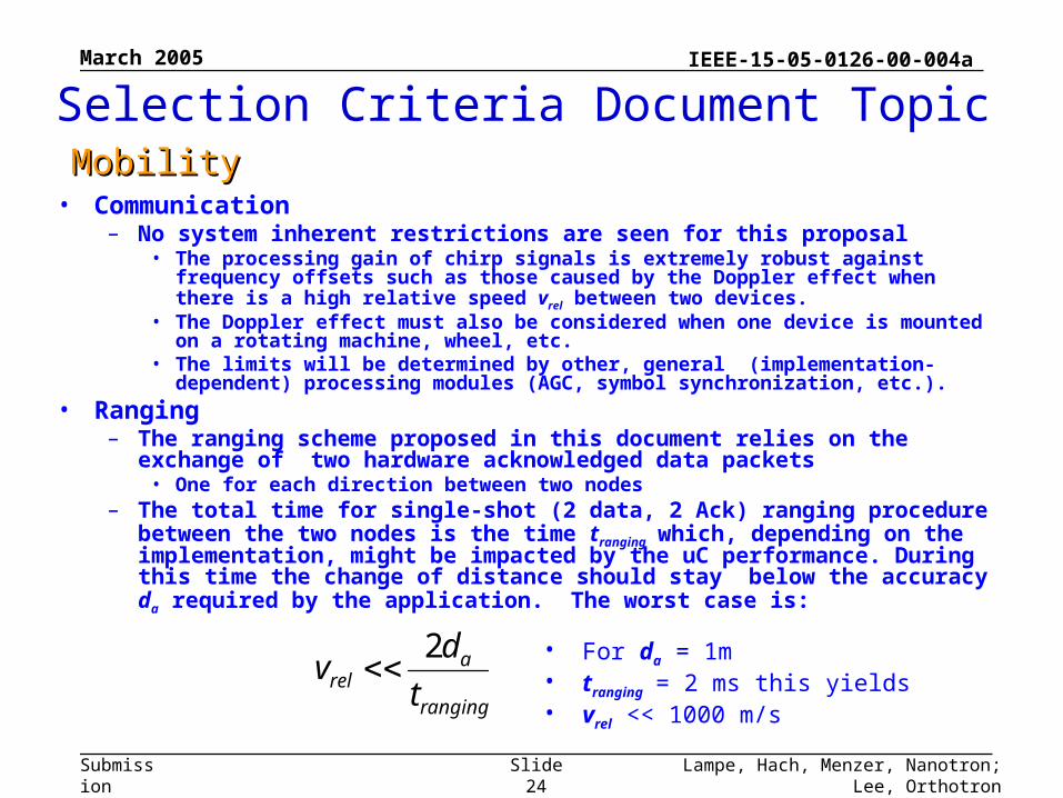
MobilityMobility• Communication
– No system inherent restrictions are seen for this proposal• The processing gain of chirp signals is extremely robust against frequency offsets
such as those caused by the Doppler effect when there is a high relative speed vrel between two devices.
• The Doppler effect must also be considered when one device is mounted on a rotating machine, wheel, etc.
• The limits will be determined by other, general (implementation-dependent) processing modules (AGC, symbol synchronization, etc.).
• Ranging– The ranging scheme proposed in this document relies on the exchange of
two hardware acknowledged data packets• One for each direction between two nodes
– The total time for single-shot (2 data, 2 Ack) ranging procedure between the two nodes is the time tranging which, depending on the implementation, might be impacted by the uC performance. During this time the change of distance should stay below the accuracy da required by the application. The worst case is:
• For da = 1m• tranging = 2 ms this yields • vrel << 1000 m/sranging
arel t
dv
2
Selection Criteria Document Topic
March 2005
Lampe, Hach, Menzer, Nanotron; Lee, OrthotronSlide 25
IEEE-15-05-0126-00-004a
Submission
Selection Criteria Document TopicMAC Protocol SupplementMAC Protocol Supplement
There are very minimal anticipated changes to the 15.4 MAC to support the proposed Alt-PHY. – Three channels are called for with this proposal and it is
recommended that the mechanism of channel bands from the proposed methods of TG4b be used to support the new channels.
– There will be an addition to the PHY-SAP primitive to include the choice of data rate to be used for the next packet. This is a new field.
Ranging calls for new PHY-PIB primitives are expected to be developed by the Ranging subcommittee.
March 2005
Lampe, Hach, Menzer, Nanotron; Lee, OrthotronSlide 26
IEEE-15-05-0126-00-004a
Submission
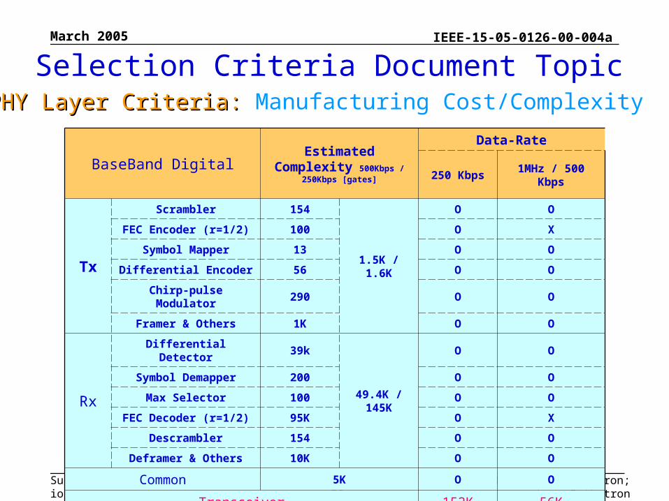
Selection Criteria Document TopicPHY Layer Criteria: PHY Layer Criteria: Manufacturing Cost/Complexity
BaseBand Digital Estimated Complexity 500Kbps / 250Kbps [gates]
Data-Rate
250 Kbps 1MHz / 500 Kbps
Tx
Scrambler 154
1.5K / 1.6K
O O
FEC Encoder (r=1/2) 100 O X
Symbol Mapper 13 O O
Differential Encoder 56 O O
Chirp-pulse Modulator 290 O O
Framer & Others 1K O O
Rx
Differential Detector 39k
49.4K / 145K
O O
Symbol Demapper 200 O O
Max Selector 100 O O
FEC Decoder (r=1/2) 95K O X
Descrambler 154 O O
Deframer & Others 10K O O
Common 5K O O
Transceiver 152K 56K
March 2005
Lampe, Hach, Menzer, Nanotron; Lee, OrthotronSlide 27
IEEE-15-05-0126-00-004a
Submission
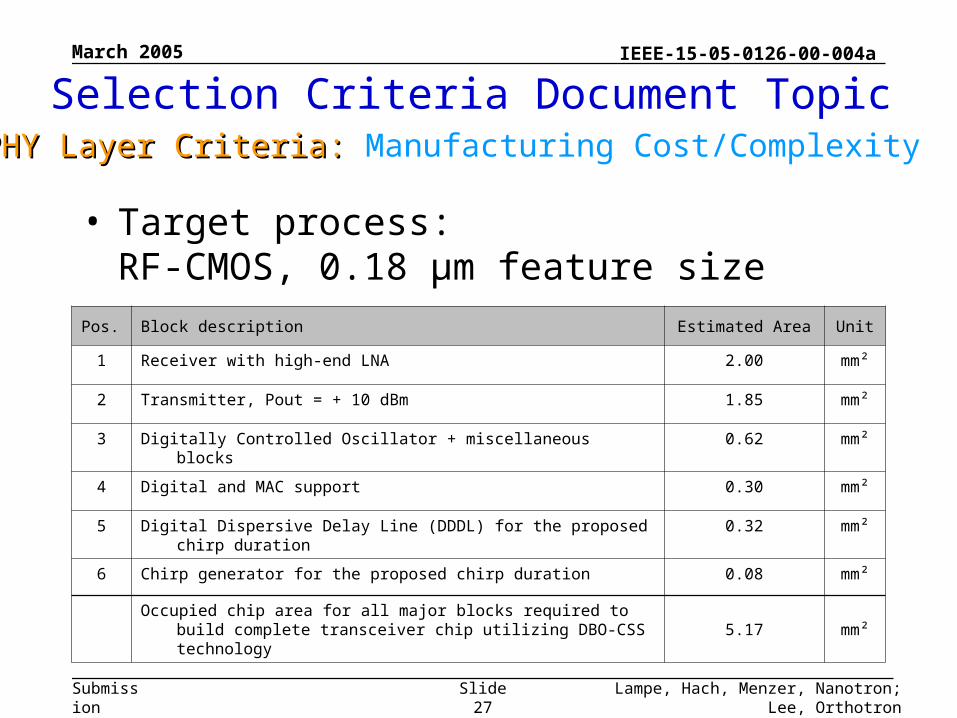
Selection Criteria Document TopicPHY Layer Criteria: PHY Layer Criteria: Manufacturing Cost/Complexity
• Target process:RF-CMOS, 0.18 µm feature size
Pos. Block description Estimated Area Unit
1 Receiver with high-end LNA 2.00 mm²
2 Transmitter, Pout = + 10 dBm 1.85 mm²
3 Digitally Controlled Oscillator + miscellaneous blocks 0.62 mm²
4 Digital and MAC support 0.30 mm²
5 Digital Dispersive Delay Line (DDDL) for the proposed chirp duration 0.32 mm²
6 Chirp generator for the proposed chirp duration 0.08 mm²
Occupied chip area for all major blocks required to build complete transceiver chip utilizing DBO-CSS technology 5.17 mm²
March 2005
Lampe, Hach, Menzer, Nanotron; Lee, OrthotronSlide 28
IEEE-15-05-0126-00-004a
Submission
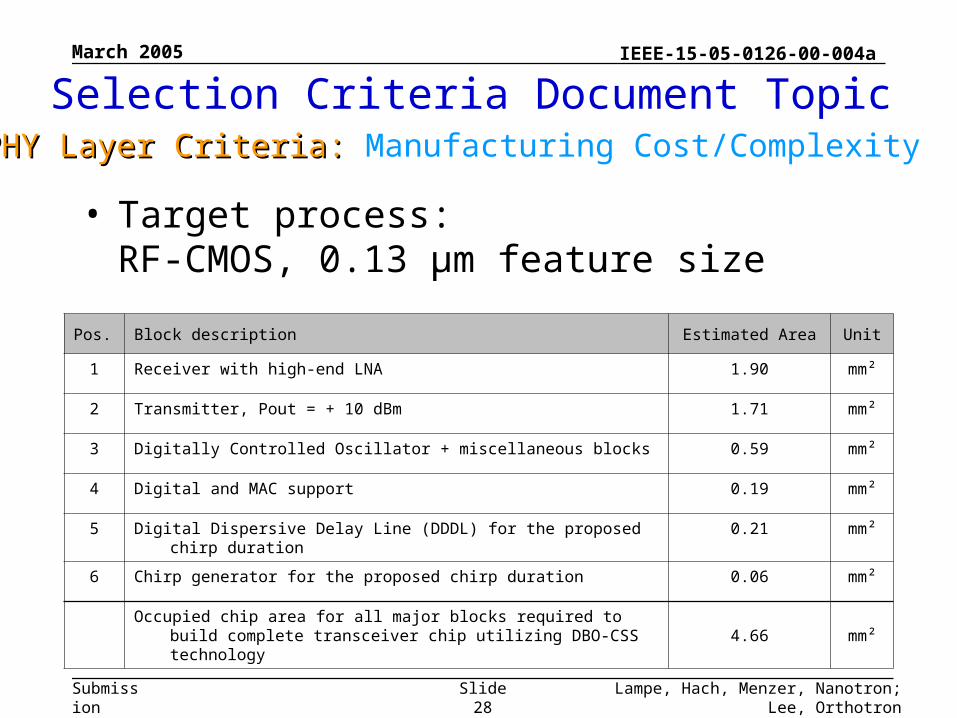
Selection Criteria Document TopicPHY Layer Criteria: PHY Layer Criteria: Manufacturing Cost/Complexity
• Target process:RF-CMOS, 0.13 µm feature size
Pos. Block description Estimated Area Unit
1 Receiver with high-end LNA 1.90 mm²
2 Transmitter, Pout = + 10 dBm 1.71 mm²
3 Digitally Controlled Oscillator + miscellaneous blocks 0.59 mm²
4 Digital and MAC support 0.19 mm²
5 Digital Dispersive Delay Line (DDDL) for the proposed chirp duration 0.21 mm²
6 Chirp generator for the proposed chirp duration 0.06 mm²
Occupied chip area for all major blocks required to build complete transceiver chip utilizing DBO-CSS technology 4.66 mm²
March 2005
Lampe, Hach, Menzer, Nanotron; Lee, OrthotronSlide 29
IEEE-15-05-0126-00-004a
Submission
Selection Criteria Document TopicPHY Layer Criteria: PHY Layer Criteria: Size and Form Factor
The implementation of the DBO-CSS proposal will be much less than SD Memory at the onset– Following the form factors of Bluetooth and IEEE 802.15.4 / ZigBee
The implementation of this device into a single chip is relatively straightforward– As evidenced in the “Unit Manufacturing Complexity” slides
March 2005
Lampe, Hach, Menzer, Nanotron; Lee, OrthotronSlide 30
IEEE-15-05-0126-00-004a
Submission
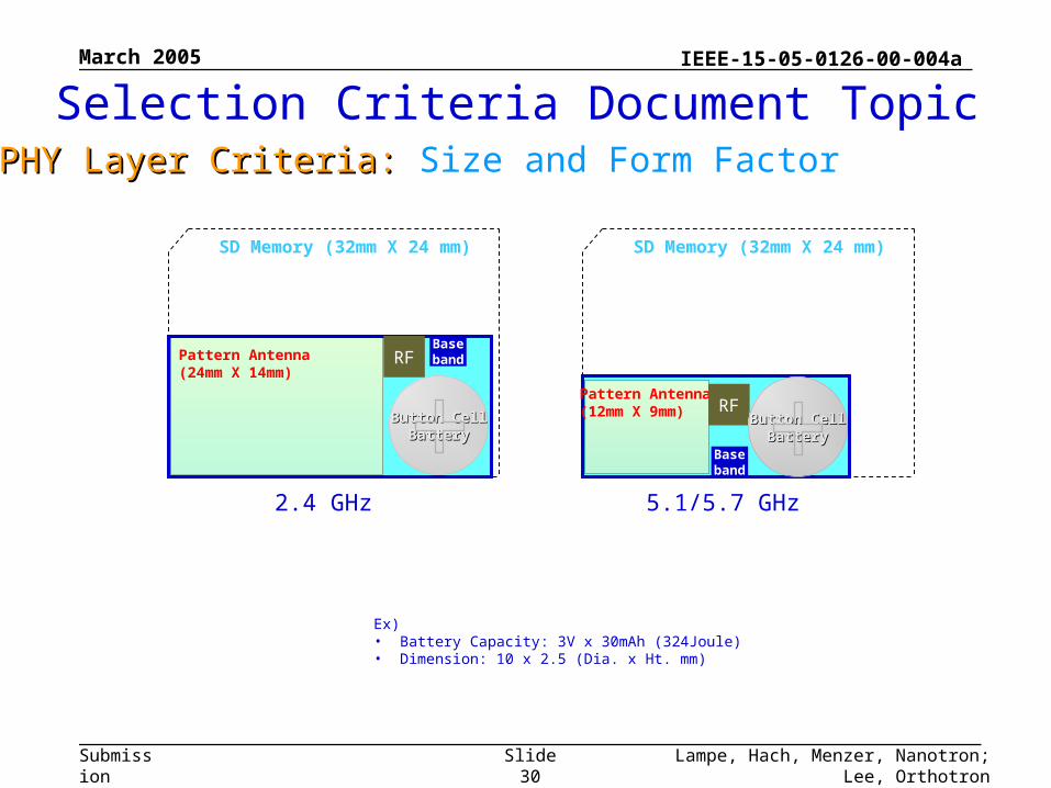
SD Memory (32mm X 24 mm)
Ex)• Battery Capacity: 3V x 30mAh (324Joule)• Dimension: 10 x 2.5 (Dia. x Ht. mm)
SD Memory (32mm X 24 mm)
2.4 GHz
BasebandRFPattern Antenna
(24mm X 14mm)
Button CellButton CellBatteryBattery
5.1/5.7 GHz
Pattern Antenna(12mm X 9mm)
Baseband
RFButton CellButton Cell
BatteryBattery
Selection Criteria Document TopicPHY Layer Criteria: PHY Layer Criteria: Size and Form Factor
March 2005
Lampe, Hach, Menzer, Nanotron; Lee, OrthotronSlide 31
IEEE-15-05-0126-00-004a
Submission
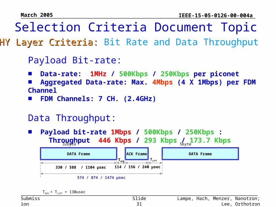
DATA Frame ACK Frame DATA Frame
TACKTLIFT
330 / 588 / 1104 μsec 114 / 156 / 240 μsec
Payload: 32byte 5byte
574 / 874 / 1474 μsec
TACK + TLIFT = 130usec
Payload Bit-rate:
■ Data-rate: 1MHz / 500Kbps / 250Kbps per piconet■ Aggregated Data-rate: Max. 4Mbps (4 X 1Mbps) per FDM Channel■ FDM Channels: 7 CH. (2.4GHz)
Data Throughput:
■ Payload bit-rate 1Mbps / 500Kbps / 250Kbps : Throughput 446 Kbps / 293 Kbps / 173.7 Kbps
Selection Criteria Document TopicPHY Layer Criteria: PHY Layer Criteria: Bit Rate and Data Throughput
March 2005
Lampe, Hach, Menzer, Nanotron; Lee, OrthotronSlide 32
IEEE-15-05-0126-00-004a
Submission
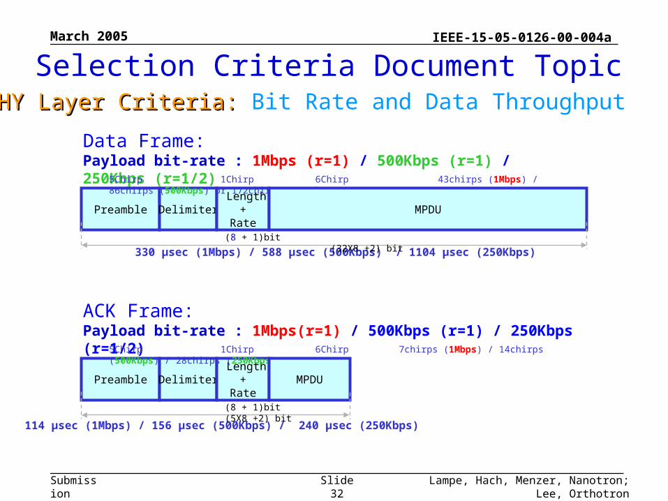
Data Frame:Payload bit-rate : 1Mbps (r=1) / 500Kbps (r=1) / 250Kbps (r=1/2)
Preamble Delimiter Length
+Rate
5Chirp 1Chirp 6Chirp 43chirps (1Mbps) / 86chirps (500Kbps) or 172chirps (250Kbps)
MPDU
330 μsec (1Mbps) / 588 μsec (500Kbps) / 1104 μsec (250Kbps)(8 + 1)bit (32X8 +2) bit
ACK Frame:Payload bit-rate : 1Mbps(r=1) / 500Kbps (r=1) / 250Kbps (r=1/2)
Preamble Delimiter Length
+Rate
5Chirp 1Chirp 6Chirp 7chirps (1Mbps) / 14chirps (500Kbps) / 28chirps (250Kbps)
MPDU
114 μsec (1Mbps) / 156 μsec (500Kbps) / 240 μsec (250Kbps)
(8 + 1)bit (5X8 +2) bit
Selection Criteria Document TopicPHY Layer Criteria: PHY Layer Criteria: Bit Rate and Data Throughput
March 2005
Lampe, Hach, Menzer, Nanotron; Lee, OrthotronSlide 33
IEEE-15-05-0126-00-004a
Submission
Selection Criteria Document TopicPHY Layer Criteria: PHY Layer Criteria: Bit Rate and Data Throughput
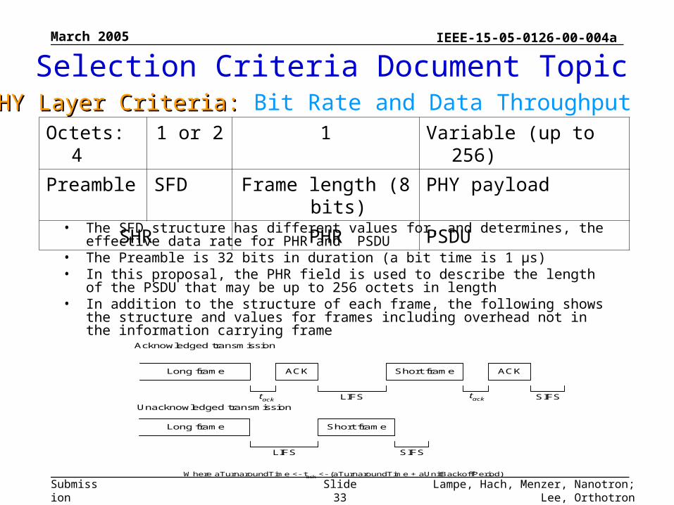
• The SFD structure has different values for, and determines, the effective data rate for PHR and PSDU
• The Preamble is 32 bits in duration (a bit time is 1 µs)• In this proposal, the PHR field is used to describe the length of the PSDU that
may be up to 256 octets in length• In addition to the structure of each frame, the following shows the structure and
values for frames including overhead not in the information carrying frame
Octets: 4 1 or 2 1 Variable (up to 256)
Preamble SFD Frame length (8 bits) PHY payload
SHR PHR PSDU
ACK Short frame ACKLong frame
SIFStacktack LIFS
Short frame
SIFSLIFS
Long frame
Acknowledged transmission
Unacknowledged transmission
Where aTurnaroundTime <- tack <- (aTurnaroundTime + aUnitBackoffPeriod)
March 2005
Lampe, Hach, Menzer, Nanotron; Lee, OrthotronSlide 34
IEEE-15-05-0126-00-004a
Submission
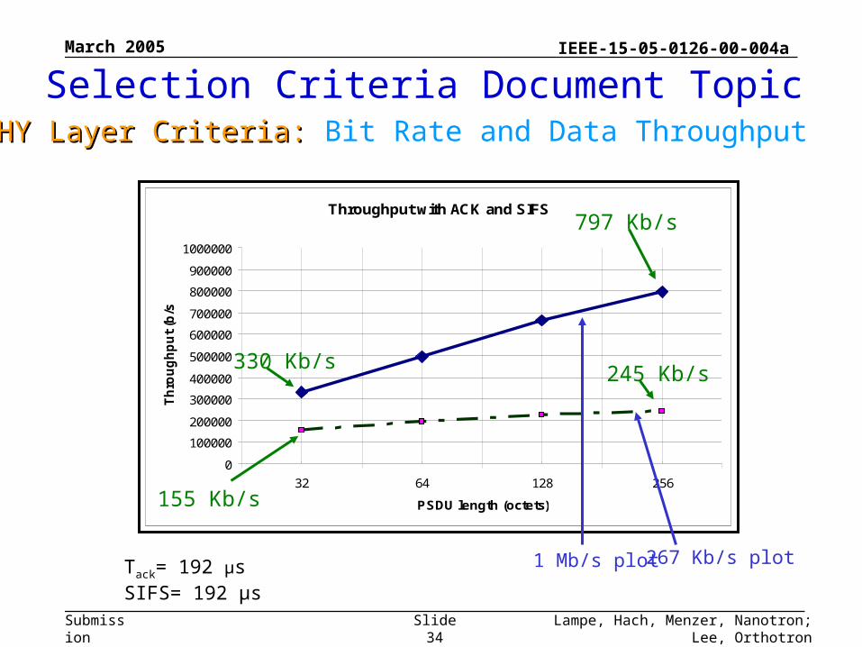
Throughput with ACK and SIFS
0
100000
200000
300000
400000
500000
600000
700000
800000
900000
1000000
32 64 128 256
PSDU length (octets)
Th
rou
gh
pu
t (b
/s)
267 Kb/s plot1 Mb/s plotTack= 192 µsSIFS= 192 µs
330 Kb/s
155 Kb/s
797 Kb/s
245 Kb/s
Selection Criteria Document TopicPHY Layer Criteria: PHY Layer Criteria: Bit Rate and Data Throughput
March 2005
Lampe, Hach, Menzer, Nanotron; Lee, OrthotronSlide 35
IEEE-15-05-0126-00-004a
Submission
Separating Piconets by frequency division– This DBO-CSS proposal includes a mechanism for FDMA by
including the three frequency bands used by 802.11 b, g and also 802.15.3• It is believed that the use of these bands will provide sufficient
orthogonality– The proposed chirp signal has a rolloff factor of 0.25 which in
conjunction with the space between the adjacent frequency bands allows filtering out of band emissions easily and inexpensively.
Selection Criteria Document TopicSimultaneously Operating PiconetsSimultaneously Operating Piconets
March 2005
Lampe, Hach, Menzer, Nanotron; Lee, OrthotronSlide 36
IEEE-15-05-0126-00-004a
Submission
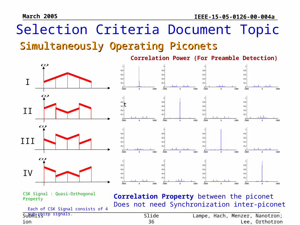
Each of CSK Signal consists of 4 sub-chirp signals.
I
II
III
IV
-5000 0 50000
0.2
0.4
0.6
0.8
1
-5000 0 50000
0.2
0.4
0.6
0.8
1
-5000 0 50000
0.2
0.4
0.6
0.8
1
-5000 0 50000
0.2
0.4
0.6
0.8
1
-5000 0 50000
0.2
0.4
0.6
0.8
1
-5000 0 50000
0.2
0.4
0.6
0.8
1
-5000 0 50000
0.2
0.4
0.6
0.8
1
-5000 0 50000
0.2
0.4
0.6
0.8
1
-5000 0 50000
0.2
0.4
0.6
0.8
1
-5000 0 50000
0.2
0.4
0.6
0.8
1
-5000 0 50000
0.2
0.4
0.6
0.8
1
-5000 0 50000
0.2
0.4
0.6
0.8
1
-5000 0 50000
0.2
0.4
0.6
0.8
1
-5000 0 50000
0.2
0.4
0.6
0.8
1
-5000 0 50000
0.2
0.4
0.6
0.8
1
-5000 0 50000
0.2
0.4
0.6
0.8
1
Correlation Power (For Preamble Detection)
Correlation Property between the piconetDoes not need Synchronization inter-piconet
t
CSK Signal : Quasi-Orthogonal Property
Selection Criteria Document TopicSimultaneously Operating PiconetsSimultaneously Operating Piconets
March 2005
Lampe, Hach, Menzer, Nanotron; Lee, OrthotronSlide 37
IEEE-15-05-0126-00-004a
Submission
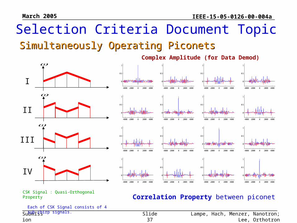
Each of CSK Signal consists of 4 sub-chirp signals.
I
II
III
IV
-4000 -2000 0 2000 4000
0
0.5
1
-4000 -2000 0 2000 4000
0
0.5
1
-4000 -2000 0 2000 4000
0
0.5
1
-4000 -2000 0 2000 4000
0
0.5
1
-4000 -2000 0 2000 4000
0
0.5
1
-4000 -2000 0 2000 4000
0
0.5
1
-4000 -2000 0 2000 4000
0
0.5
1
-4000 -2000 0 2000 4000
0
0.5
1
-4000 -2000 0 2000 4000
0
0.5
1
-4000 -2000 0 2000 4000
0
0.5
1
-4000 -2000 0 2000 4000
0
0.5
1
-4000 -2000 0 2000 4000
0
0.5
1
-4000 -2000 0 2000 4000
0
0.5
1
-4000 -2000 0 2000 4000
0
0.5
1
-4000 -2000 0 2000 4000
0
0.5
1
-4000 -2000 0 2000 4000
0
0.5
1
Complex Amplitude (for Data Demod)
Correlation Property between piconetCSK Signal : Quasi-Orthogonal Property
Selection Criteria Document TopicSimultaneously Operating PiconetsSimultaneously Operating Piconets
March 2005
Lampe, Hach, Menzer, Nanotron; Lee, OrthotronSlide 38
IEEE-15-05-0126-00-004a
Submission
I
II
III
IV
t
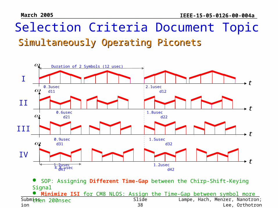
Duration of 2 Symbols (12 usec)
0.3usec 2.1usec d11 d12
0.6usec 1.8usec d21 d22
0.9usec 1.5usec d31 d32
1.2usec 1.2usec d41 d42
t
t
t
4.8 usec
SOP: Assigning Different Time-Gap between the Chirp-Shift-Keying Signal Minimize ISI for CM8 NLOS: Assign the Time-Gap between symbol more then 200nsec
Selection Criteria Document TopicSimultaneously Operating PiconetsSimultaneously Operating Piconets
March 2005
Lampe, Hach, Menzer, Nanotron; Lee, OrthotronSlide 39
IEEE-15-05-0126-00-004a
Submission
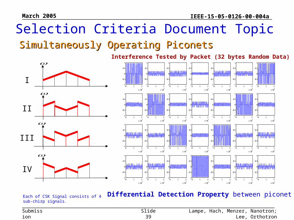
Each of CSK Signal consists of 4 sub-chirp signals. Differential Detection Property between piconet
I
II
III
IV
0 1 2
x 104
-1
-0.5
0
0.5
1
0 1 2
x 104
-1
-0.5
0
0.5
1
0 1 2
x 104
-1
-0.5
0
0.5
1
0 1 2
x 104
-1
-0.5
0
0.5
1
0 1 2
x 104
-1
-0.5
0
0.5
1
0 1 2
x 104
-1
-0.5
0
0.5
1
0 1 2
x 104
-1
-0.5
0
0.5
1
0 1 2
x 104
-1
-0.5
0
0.5
1
0 1 2
x 104
-1
-0.5
0
0.5
1
0 1 2
x 104
-1
-0.5
0
0.5
1
0 1 2
x 104
-1
-0.5
0
0.5
1
0 1 2
x 104
-1
-0.5
0
0.5
1
0 1 2
x 104
-1
-0.5
0
0.5
1
0 1 2
x 104
-1
-0.5
0
0.5
1
0 1 2
x 104
-1
-0.5
0
0.5
1
0 1 2
x 104
-1
-0.5
0
0.5
1
0 1 2
x 104
-1
-0.5
0
0.5
1
0 1 2
x 104
-1
-0.5
0
0.5
1
0 1 2
x 104
-1
-0.5
0
0.5
1
0 1 2
x 104
-1
-0.5
0
0.5
1
0 1 2
x 104
-1
-0.5
0
0.5
1
0 1 2
x 104
-1
-0.5
0
0.5
1
0 1 2
x 104
-1
-0.5
0
0.5
1
0 1 2
x 104
-1
-0.5
0
0.5
1
0 1 2
x 104
-1
-0.5
0
0.5
1
0 1 2
x 104
-1
-0.5
0
0.5
1
0 1 2
x 104
-1
-0.5
0
0.5
1
0 1 2
x 104
-1
-0.5
0
0.5
1
Interference Tested by Packet (32 bytes Random Data)
Selection Criteria Document TopicSimultaneously Operating PiconetsSimultaneously Operating Piconets
March 2005
Lampe, Hach, Menzer, Nanotron; Lee, OrthotronSlide 40
IEEE-15-05-0126-00-004a
Submission
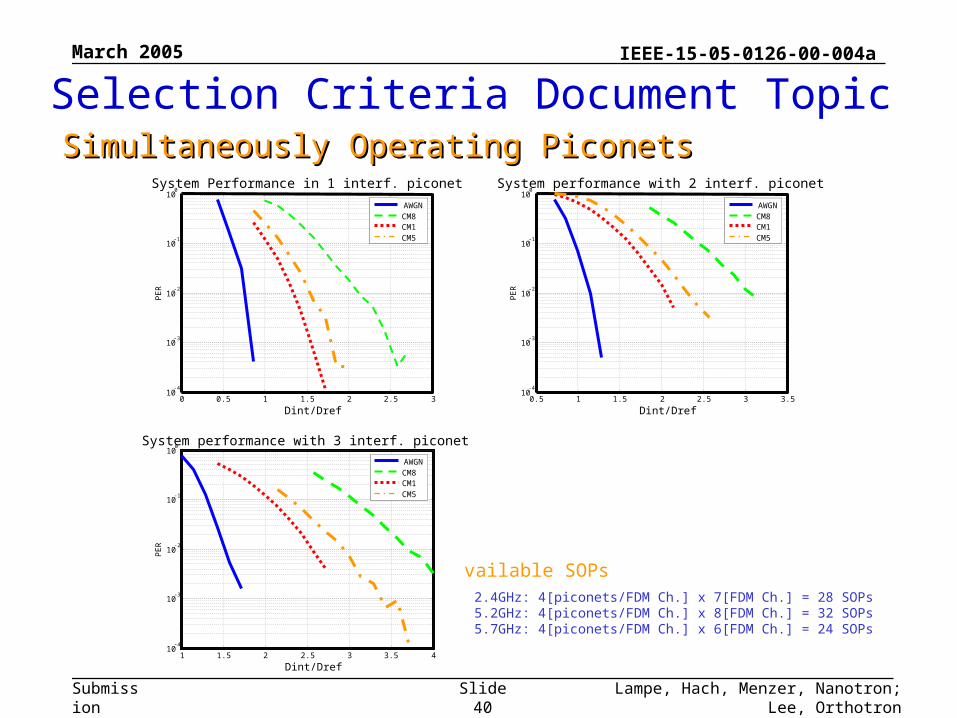
Available SOPs
2.4GHz: 4[piconets/FDM Ch.] x 7[FDM Ch.] = 28 SOPs 5.2GHz: 4[piconets/FDM Ch.] x 8[FDM Ch.] = 32 SOPs 5.7GHz: 4[piconets/FDM Ch.] x 6[FDM Ch.] = 24 SOPs
Selection Criteria Document TopicSimultaneously Operating PiconetsSimultaneously Operating Piconets
0 0.5 1 1.5 2 2.5 310
-4
10-3
10-2
10-1
100
Dint/Dref
PE
R
System Performance in 1 interf. piconet
AWGNCM8CM1CM5
0.5 1 1.5 2 2.5 3 3.510
-4
10-3
10-2
10-1
100
Dint/Dref
PE
R
System performance with 2 interf. piconet
AWGNCM8CM1CM5
1 1.5 2 2.5 3 3.5 410
-4
10-3
10-2
10-1
100
Dint/Dref
PE
R
System performance with 3 interf. piconet
AWGNCM8CM1CM5
March 2005
Lampe, Hach, Menzer, Nanotron; Lee, OrthotronSlide 41
IEEE-15-05-0126-00-004a
Submission
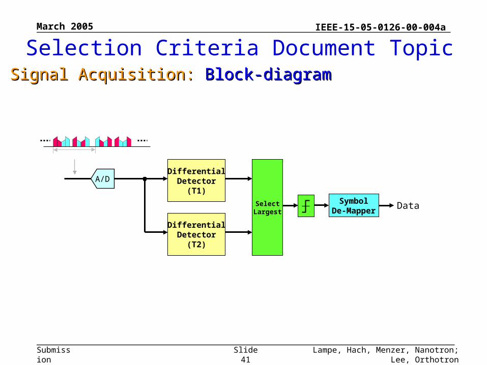
Selection Criteria Document TopicSignal Acquisition: Signal Acquisition: Block-diagramBlock-diagram
DifferentialDetector
(T1)Symbol
De-MapperSelect
LargestData
A/D
DifferentialDetector
(T2)
March 2005
Lampe, Hach, Menzer, Nanotron; Lee, OrthotronSlide 42
IEEE-15-05-0126-00-004a
Submission
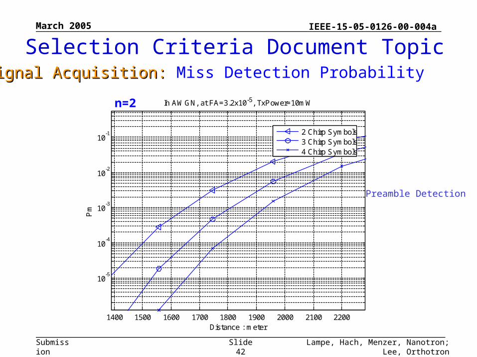
1400 1500 1600 1700 1800 1900 2000 2100 2200
10-5
10-4
10-3
10-2
10-1
In AWGN, at FA=3.2x10⁻⁵, TxPower=10mW
Distance : meter
Pm
2 Chirp Symbols3 Chirp Symbols4 Chirp Symbols
Preamble Detection
Selection Criteria Document TopicSignal Acquisition: Signal Acquisition: Miss Detection Probability
n=2
March 2005
Lampe, Hach, Menzer, Nanotron; Lee, OrthotronSlide 43
IEEE-15-05-0126-00-004a
Submission
Although DBO-CSS could use a shorter preamble, for consistency with IEEE 802.15.4-2003 this DBO-CSS proposal is based upon a preamble of 32 symbols which at 1MS/s is 32 µs
Existing implementations demonstrate that modules, which might be required to be adjusted for reception (gain control, frequency control, peak value estimation, etc.), can settle in this time
Selection Criteria Document TopicSignal AcquisitionSignal Acquisition
March 2005
Lampe, Hach, Menzer, Nanotron; Lee, OrthotronSlide 44
IEEE-15-05-0126-00-004a
Submission
Selection Criteria Document TopicClear Channel AssessmentClear Channel Assessment
March 2005
Lampe, Hach, Menzer, Nanotron; Lee, OrthotronSlide 45
IEEE-15-05-0126-00-004a
Submission
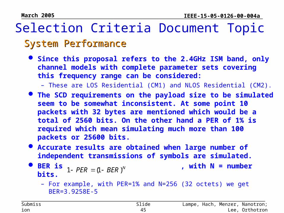
Since this proposal refers to the 2.4GHz ISM band, only channel models with complete parameter sets covering this frequency range can be considered:– These are LOS Residential (CM1) and NLOS Residential (CM2).
The SCD requirements on the payload size to be simulated seem to be somewhat inconsistent. At some point 10 packets with 32 bytes are mentioned which would be a total of 2560 bits. On the other hand a PER of 1% is required which mean simulating much more than 100 packets or 25600 bits.
Accurate results are obtained when large number of independent transmissions of symbols are simulated.
BER is , with N = number bits.– For example, with PER=1% and N=256 (32 octets) we get
BER=3.9258E-5
NBERPER )1(1
System PerformanceSystem Performance
Selection Criteria Document Topic
March 2005
Lampe, Hach, Menzer, Nanotron; Lee, OrthotronSlide 46
IEEE-15-05-0126-00-004a
Submission
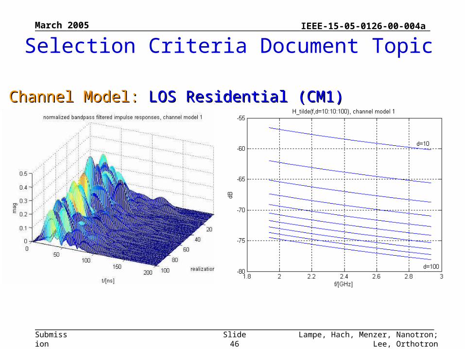
Channel Model: Channel Model: LOS Residential (CM1)LOS Residential (CM1)
Selection Criteria Document Topic
March 2005
Lampe, Hach, Menzer, Nanotron; Lee, OrthotronSlide 47
IEEE-15-05-0126-00-004a
Submission
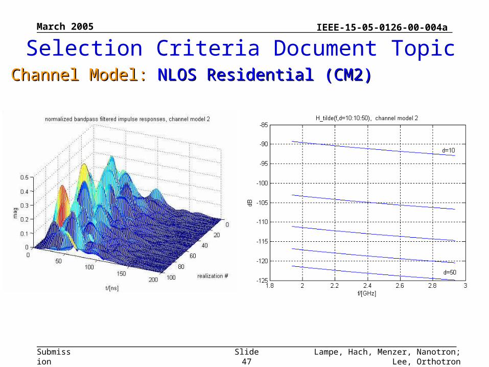
Channel Model: Channel Model: NLOS Residential (CM2)NLOS Residential (CM2)
Selection Criteria Document Topic
March 2005
Lampe, Hach, Menzer, Nanotron; Lee, OrthotronSlide 49
IEEE-15-05-0126-00-004a
Submission
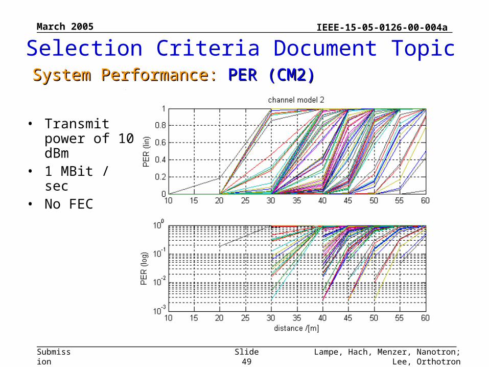
• Transmit power of 10 dBm
• 1 MBit / sec• No FEC
System Performance: System Performance: PER (CM2)PER (CM2)
Selection Criteria Document Topic
March 2005
Lampe, Hach, Menzer, Nanotron; Lee, OrthotronSlide 50
IEEE-15-05-0126-00-004a
Submission
Simulation over 100 channel impulse responses (as required in the SCD) were performed for channel model 1 and channel model 2.
No bit errors could be observed on channel model 1 (simulated range was 10 to 2000m). This is not really surprising because this model has a very moderate increase of attenuation over range (n=1.79)
The results for channel model 2 are presented. The parameter n=4.48 indicates a very high attenuation for higher ranges. The results were interpreted as PER respectively and for convenience were plotted twice (linear and log y scale).
System PerformanceSystem Performance
Selection Criteria Document Topic
March 2005
Lampe, Hach, Menzer, Nanotron; Lee, OrthotronSlide 51
IEEE-15-05-0126-00-004a
Submission
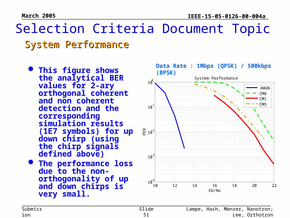
This figure shows the analytical BER values for 2-ary orthogonal coherent and non coherent detection and the corresponding simulation results (1E7 symbols) for up down chirp (using the chirp signals defined above)
The performance loss due to the non-orthogonality of up and down chirps is very small.
Selection Criteria Document TopicSystem PerformanceSystem Performance
Data Rate : 1Mbps (QPSK) / 500kbps (BPSK)
10 12 14 16 18 20 2210
-4
10-3
10-2
10-1
100
Eb/No
PE
R
System Performance
AWGNCM8CM1CM5
March 2005
Lampe, Hach, Menzer, Nanotron; Lee, OrthotronSlide 52
IEEE-15-05-0126-00-004a
Submission
Selection Criteria Document TopicSystem PerformanceSystem Performance
1800 2000 2200 2400 2600 2800 300010
-4
10-3
10-2
10-1
100
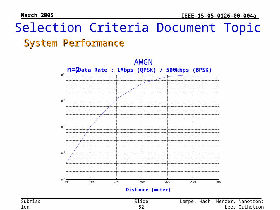
AWGN(Data Rate : 1Mbps (QPSK) / 500kbps (BPSK)n=2
Distance (meter)
March 2005
Lampe, Hach, Menzer, Nanotron; Lee, OrthotronSlide 53
IEEE-15-05-0126-00-004a
Submission
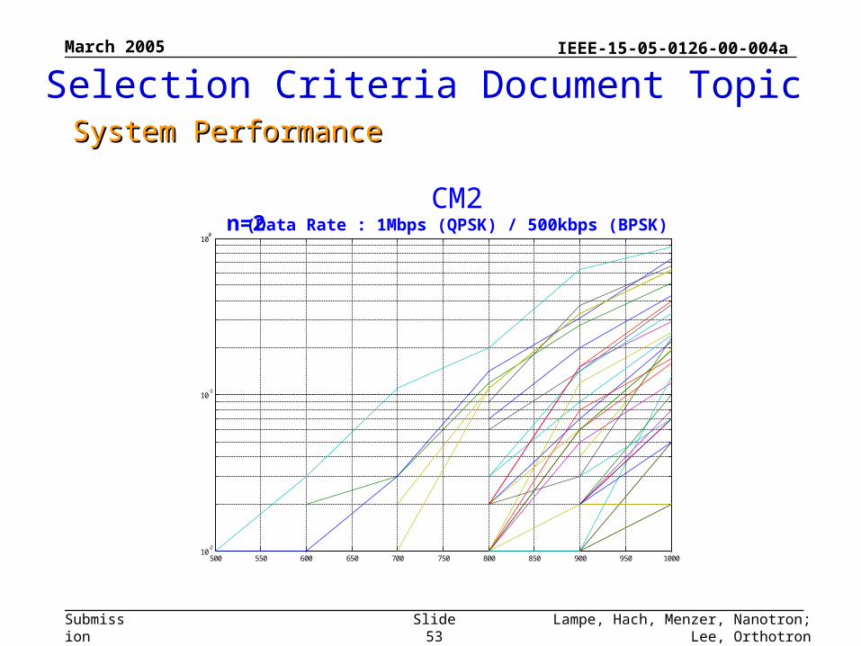
CM2(Data Rate : 1Mbps (QPSK) / 500kbps (BPSK)
500 550 600 650 700 750 800 850 900 950 100010
-2
10-1
100
n=2
Selection Criteria Document TopicSystem PerformanceSystem Performance
March 2005
Lampe, Hach, Menzer, Nanotron; Lee, OrthotronSlide 54
IEEE-15-05-0126-00-004a
Submission
TOA EstimationTOA Estimation Coarse: Differential demodulation peak Fine: Correlation peak Precise: Receive signal post-processing
(Spectrum estimation or curve fitting) Simulation Results
TOA ProcessingTOA Processing
SDS TWR Technique Error Sensitivity Analysis Simulation Results
Selection Criteria Document TopicRangingRanging
March 2005
Lampe, Hach, Menzer, Nanotron; Lee, OrthotronSlide 55
IEEE-15-05-0126-00-004a
Submission
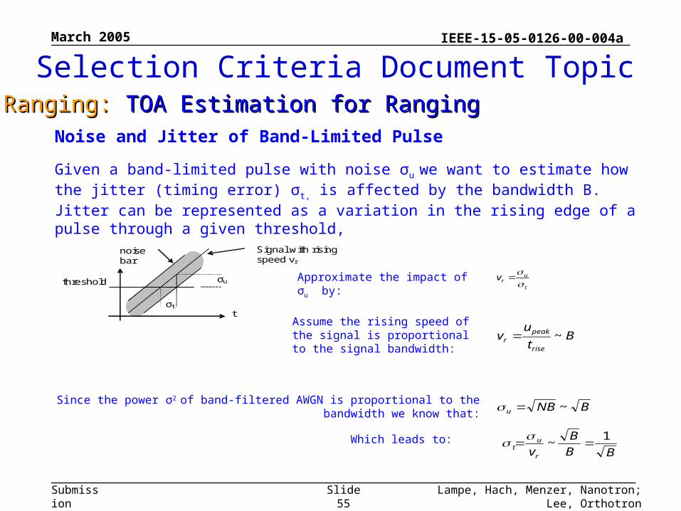
Noise and Jitter of Band-Limited Pulse
Given a band-limited pulse with noise σu we want to estimate how the jitter (timing error) σt, is affected by the bandwidth B. Jitter can be represented as a variation in the rising edge of a pulse through a given threshold,
Since the power σ2 of band-filtered AWGN is proportional to the bandwidth we know that:
t
urv
BB
B
vr
ut
1~
σu threshold
σt t
u Signal with rising speed vr
noise bar
Approximate the impact of σu by:
Bt
uv
rise
peakr ~
Assume the rising speed of the signal is proportional to the signal bandwidth:
Which leads to:
BNBu ~
Selection Criteria Document TopicRanging: Ranging: TOA Estimation for RangingTOA Estimation for Ranging
March 2005
Lampe, Hach, Menzer, Nanotron; Lee, OrthotronSlide 56
IEEE-15-05-0126-00-004a
Submission
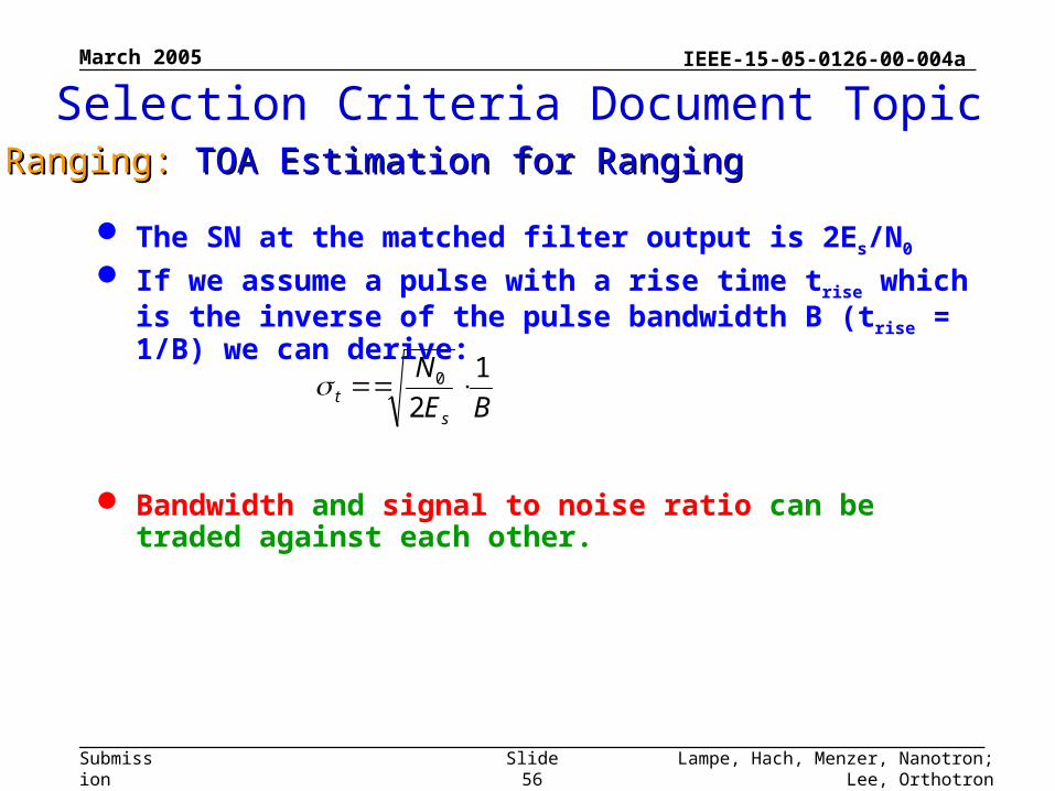
The SN at the matched filter output is 2Es/N0
If we assume a pulse with a rise time trise which is the inverse of the pulse bandwidth B (trise = 1/B) we can derive:
Bandwidth and signal to noise ratio can be traded against each other.
BE
N
st
1
20
Selection Criteria Document TopicRanging: Ranging: TOA Estimation for RangingTOA Estimation for Ranging
March 2005
Lampe, Hach, Menzer, Nanotron; Lee, OrthotronSlide 57
IEEE-15-05-0126-00-004a
Submission
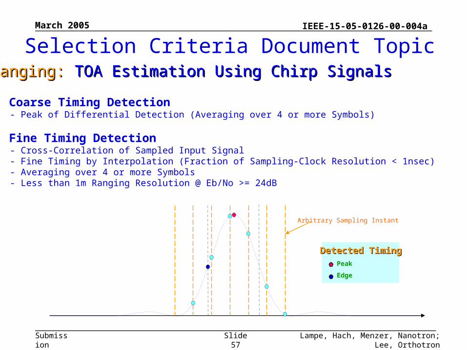
■ Coarse Timing Detection - Peak of Differential Detection (Averaging over 4 or more Symbols)
■ Fine Timing Detection - Cross-Correlation of Sampled Input Signal - Fine Timing by Interpolation (Fraction of Sampling-Clock Resolution < 1nsec) - Averaging over 4 or more Symbols - Less than 1m Ranging Resolution @ Eb/No >= 24dB
Arbitrary Sampling Instant
Detected TimingDetected TimingPeak
Edge
Selection Criteria Document TopicRanging: Ranging: TOA Estimation Using Chirp SignalsTOA Estimation Using Chirp Signals
March 2005
Lampe, Hach, Menzer, Nanotron; Lee, OrthotronSlide 58
IEEE-15-05-0126-00-004a
Submission
One special property of chirp signals is that
Time shifts can be transformed into
frequency shifts
thus
TOA estimation can be transformed to spectral estimation
which has the advantage that
Wide bandwidth and high sampling frequency are not required
Selection Criteria Document TopicRanging: Ranging: TOA Estimation Using Chirp SignalsTOA Estimation Using Chirp Signals
March 2005
Lampe, Hach, Menzer, Nanotron; Lee, OrthotronSlide 59
IEEE-15-05-0126-00-004a
Submission
f
t
t
A
f
t
t
A
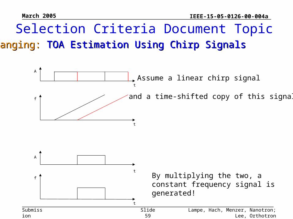
Assume a linear chirp signal
and a time-shifted copy of this signal
By multiplying the two, a constant frequency signal is generated!
Selection Criteria Document TopicRanging: Ranging: TOA Estimation Using Chirp SignalsTOA Estimation Using Chirp Signals
March 2005
Lampe, Hach, Menzer, Nanotron; Lee, OrthotronSlide 60
IEEE-15-05-0126-00-004a
Submission
f
t
t
A
t
h
f
t
t
A
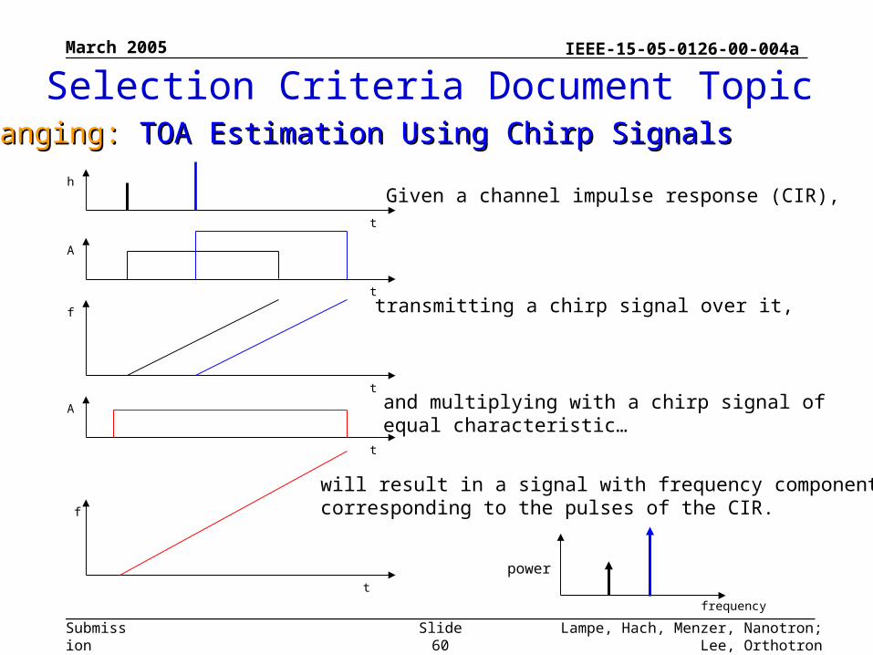
Given a channel impulse response (CIR),
transmitting a chirp signal over it,
and multiplying with a chirp signal of equal characteristic…
frequency
will result in a signal with frequency componentscorresponding to the pulses of the CIR.
power
Selection Criteria Document TopicRanging: Ranging: TOA Estimation Using Chirp SignalsTOA Estimation Using Chirp Signals
March 2005
Lampe, Hach, Menzer, Nanotron; Lee, OrthotronSlide 61
IEEE-15-05-0126-00-004a
Submission
From the estimated frequency components, the time positions of the multipath components can be calculated
and thus the time of the first arrival can be found!
Selection Criteria Document TopicRanging: Ranging: TOA Estimation Using Chirp SignalsTOA Estimation Using Chirp Signals
March 2005
Lampe, Hach, Menzer, Nanotron; Lee, OrthotronSlide 62
IEEE-15-05-0126-00-004a
Submission
Selection Criteria Document TopicRanging: Ranging: TOA Estimation Using Chirp SignalsTOA Estimation Using Chirp Signals
March 2005
Lampe, Hach, Menzer, Nanotron; Lee, OrthotronSlide 63
IEEE-15-05-0126-00-004a
Submission
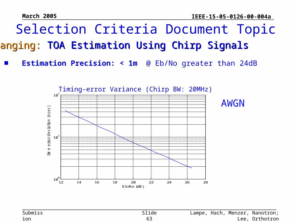
12 14 16 18 20 22 24 26 2810
0
101
102
Eb/No (dB)
tim
e e
rror
devia
tion (
nsec)
Timing-error Variance (Chirp BW: 20MHz)
■ Estimation Precision: < 1m @ Eb/No greater than 24dB
Selection Criteria Document TopicRanging: Ranging: TOA Estimation Using Chirp SignalsTOA Estimation Using Chirp Signals
AWGN
March 2005
Lampe, Hach, Menzer, Nanotron; Lee, OrthotronSlide 64
IEEE-15-05-0126-00-004a
Submission
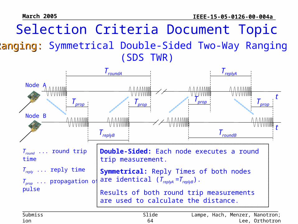
Tround ... round trip time
Treply ... reply time
Tprop ... propagation of pulse
Double-Sided: Each node executes a round trip measurement.
Symmetrical: Reply Times of both nodes are identical (TreplyA =TreplyB).
Results of both round trip measurements are used to calculate the distance.
TroundA
Tprop
TreplyA
t
Tprop Tprop
t
TroundBTreplyB
Node A
Node B
Tprop
Selection Criteria Document TopicRanging: Ranging: Symmetrical Double-Sided Two-Way Ranging (SDS TWR)
March 2005
Lampe, Hach, Menzer, Nanotron; Lee, OrthotronSlide 65
IEEE-15-05-0126-00-004a
Submission
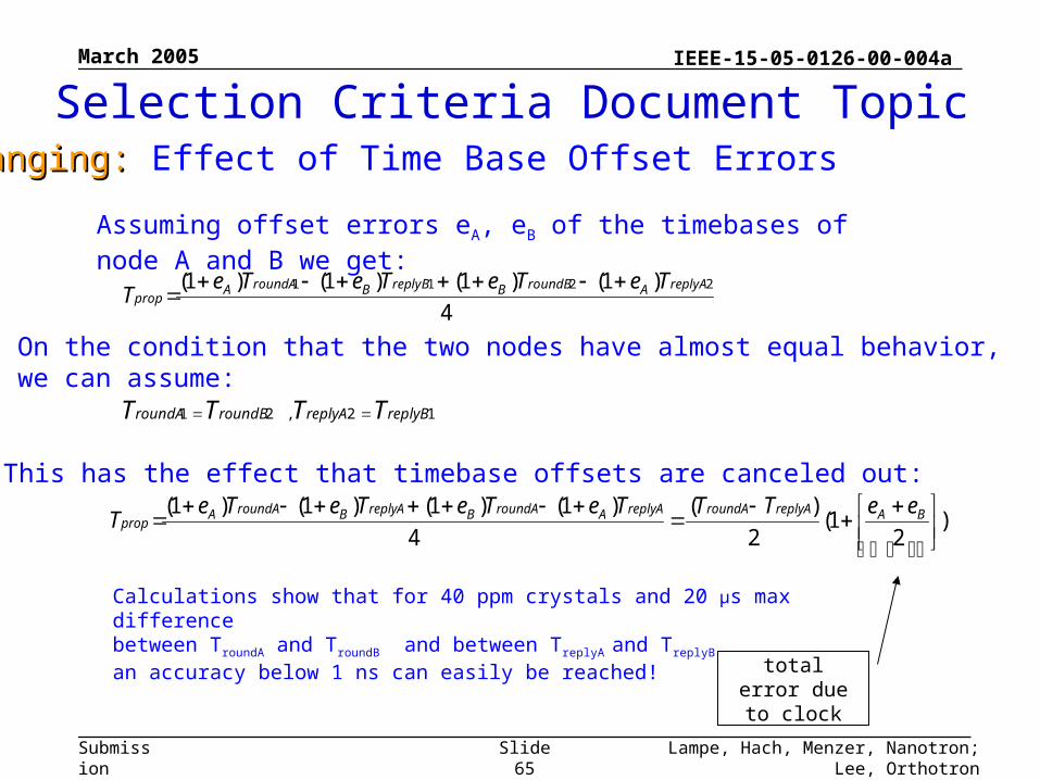
Ranging: Ranging: Effect of Time Base Offset Errors
12,21 replyBreplyAroundBroundA TTTT
4
)1()1()1()1( 2211 replyAAroundBBreplyBBroundAAprop
TeTeTeTeT
Assuming offset errors eA, eB of the timebases of node A and B we get:
On the condition that the two nodes have almost equal behavior,we can assume:
This has the effect that timebase offsets are canceled out:
)2
1(2
)(
4
)1()1()1()1(
BAreplyAroundAreplyAAroundABreplyABroundAAprop
eeTTTeTeTeTeT
total error due to clock
Calculations show that for 40 ppm crystals and 20 µs max differencebetween TroundA and TroundB and between TreplyA and TreplyB
an accuracy below 1 ns can easily be reached!
Selection Criteria Document Topic
March 2005
Lampe, Hach, Menzer, Nanotron; Lee, OrthotronSlide 66
IEEE-15-05-0126-00-004a
Submission
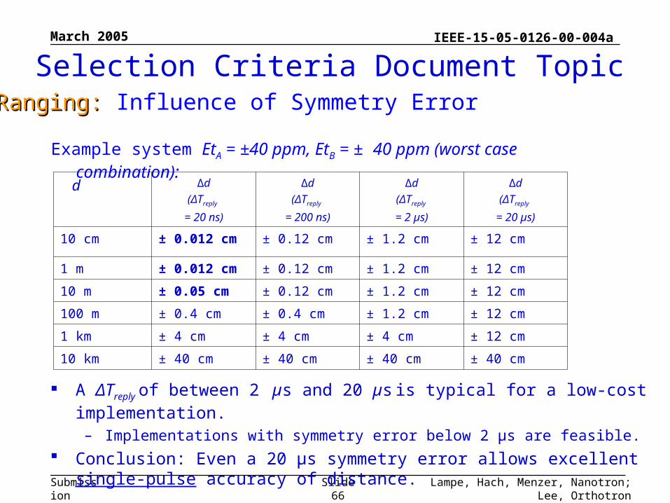
Example system EtA = ±40 ppm, EtB = ± 40 ppm (worst case combination):
d ∆d
(ΔTreply
= 20 ns)
∆d
(ΔTreply
= 200 ns)
∆d
(ΔTreply
= 2 µs)
∆d
(ΔTreply
= 20 µs)
10 cm ± 0.012 cm ± 0.12 cm ± 1.2 cm ± 12 cm
1 m ± 0.012 cm ± 0.12 cm ± 1.2 cm ± 12 cm
10 m ± 0.05 cm ± 0.12 cm ± 1.2 cm ± 12 cm
100 m ± 0.4 cm ± 0.4 cm ± 1.2 cm ± 12 cm
1 km ± 4 cm ± 4 cm ± 4 cm ± 12 cm
10 km ± 40 cm ± 40 cm ± 40 cm ± 40 cm
A ΔTreply of between 2 µs and 20 µs is typical for a low-cost implementation.
– Implementations with symmetry error below 2 µs are feasible.
Conclusion: Even a 20 µs symmetry error allows excellent single-pulse accuracy of distance.
Ranging: Ranging: Influence of Symmetry Error
Selection Criteria Document Topic
March 2005
Lampe, Hach, Menzer, Nanotron; Lee, OrthotronSlide 67
IEEE-15-05-0126-00-004a
Submission
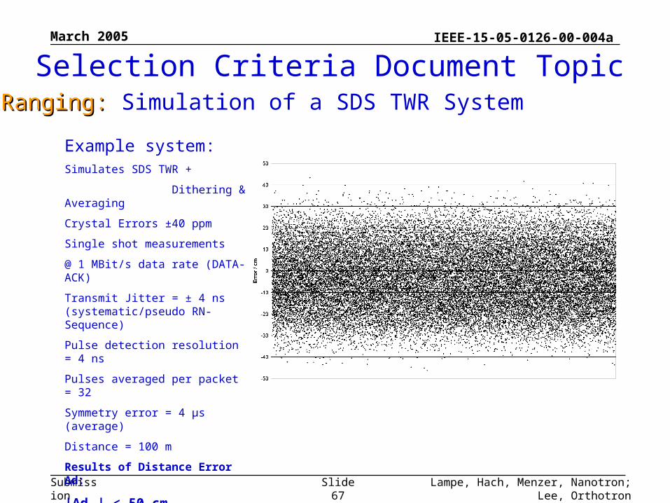
Example system:Simulates SDS TWR +
Dithering & Averaging
Crystal Errors ±40 ppm
Single shot measurements
@ 1 MBit/s data rate (DATA-ACK)
Transmit Jitter = ± 4 ns (systematic/pseudo RN-Sequence)
Pulse detection resolution = 4 ns
Pulses averaged per packet = 32
Symmetry error = 4 µs (average)
Distance = 100 m
Results of Distance Error ∆d:
|∆dWC| < 50 cm
|∆dRMS| < 20 cm
Ranging: Ranging: Simulation of a SDS TWR System
Selection Criteria Document Topic
March 2005
Lampe, Hach, Menzer, Nanotron; Lee, OrthotronSlide 68
IEEE-15-05-0126-00-004a
Submission
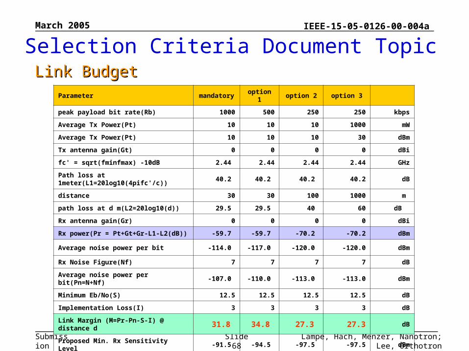
Parameter mandatory option 1 option 2 option 3
peak payload bit rate(Rb) 1000 500 250 250 kbps
Average Tx Power(Pt) 10 10 10 1000 mW
Average Tx Power(Pt) 10 10 10 30 dBm
Tx antenna gain(Gt) 0 0 0 0 dBi
fc' = sqrt(fminfmax) -10dB 2.44 2.44 2.44 2.44 GHz
Path loss at 1meter(L1=20log10(4pifc'/c)) 40.2 40.2 40.2 40.2 dB
distance 30 30 100 1000 m
path loss at d m(L2=20log10(d)) 29.5 29.5 40 60 dB
Rx antenna gain(Gr) 0 0 0 0 dBi
Rx power(Pr = Pt+Gt+Gr-L1-L2(dB)) -59.7 -59.7 -70.2 -70.2 dBm
Average noise power per bit -114.0 -117.0 -120.0 -120.0 dBm
Rx Noise Figure(Nf) 7 7 7 7 dB
Average noise power per bit(Pn=N+Nf) -107.0 -110.0 -113.0 -113.0 dBm
Minimum Eb/No(S) 12.5 12.5 12.5 12.5 dB
Implementation Loss(I) 3 3 3 3 dB
Link Margin (M=Pr-Pn-S-I) @ distance d 31.8 34.8 27.3 27.3 dB
Proposed Min. Rx Sensitivity Level -91.5 -94.5 -97.5 -97.5 dBm
Selection Criteria Document TopicLink BudgetLink Budget
March 2005
Lampe, Hach, Menzer, Nanotron; Lee, OrthotronSlide 70
IEEE-15-05-0126-00-004a
Submission
Power management aspects of this proposal are consistent with the modes identified in the IEEE 802.15.4: 2003 standard
There are no modes lacking nor added Once again, attention is called to the
1 Mbit/s basic rate of this proposal and resulting shorter “on” times for operation
Selection Criteria Document TopicPower Management ModesPower Management Modes
March 2005
Lampe, Hach, Menzer, Nanotron; Lee, OrthotronSlide 71
IEEE-15-05-0126-00-004a
Submission
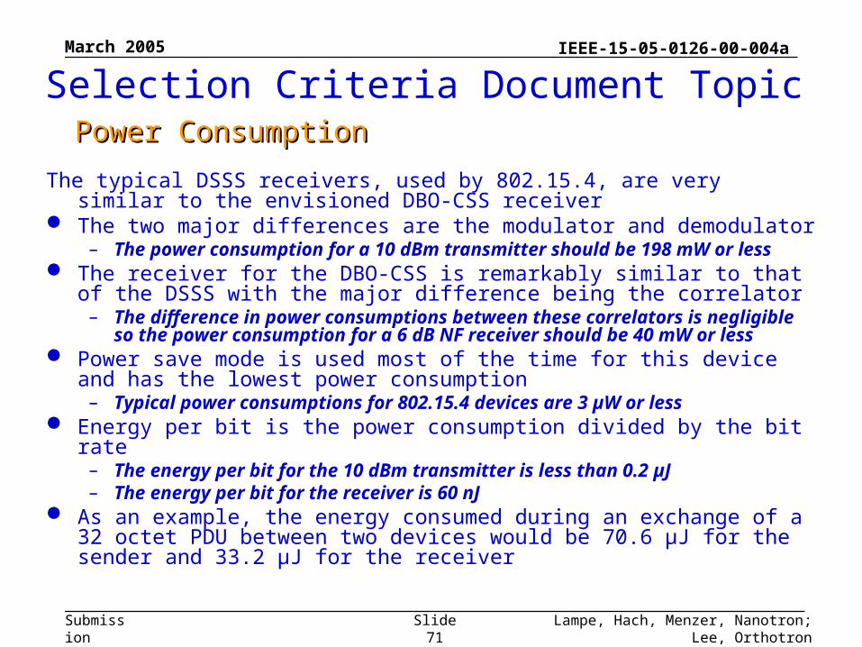
The typical DSSS receivers, used by 802.15.4, are very similar to the envisioned DBO-CSS receiver
The two major differences are the modulator and demodulator– The power consumption for a 10 dBm transmitter should be 198 mW or less
The receiver for the DBO-CSS is remarkably similar to that of the DSSS with the major difference being the correlator
– The difference in power consumptions between these correlators is negligible so the power consumption for a 6 dB NF receiver should be 40 mW or less
Power save mode is used most of the time for this device and has the lowest power consumption
– Typical power consumptions for 802.15.4 devices are 3 µW or less Energy per bit is the power consumption divided by the bit rate
– The energy per bit for the 10 dBm transmitter is less than 0.2 µJ– The energy per bit for the receiver is 60 nJ
As an example, the energy consumed during an exchange of a 32 octet PDU between two devices would be 70.6 µJ for the sender and 33.2 µJ for the receiver
Selection Criteria Document TopicPower ConsumptionPower Consumption
March 2005
Lampe, Hach, Menzer, Nanotron; Lee, OrthotronSlide 72
IEEE-15-05-0126-00-004a
Submission
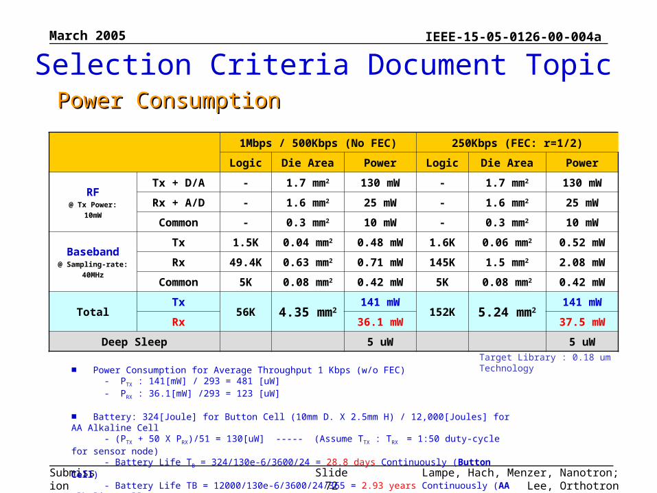
1Mbps / 500Kbps (No FEC) 250Kbps (FEC: r=1/2)
Logic Die Area Power Logic Die Area Power
RF@ Tx Power:
10mW
Tx + D/A - 1.7 mm2 130 mW - 1.7 mm2 130 mW
Rx + A/D - 1.6 mm2 25 mW - 1.6 mm2 25 mW
Common - 0.3 mm2 10 mW - 0.3 mm2 10 mW
Baseband@ Sampling-rate:
40MHz
Tx 1.5K 0.04 mm2 0.48 mW 1.6K 0.06 mm2 0.52 mW
Rx 49.4K 0.63 mm2 0.71 mW 145K 1.5 mm2 2.08 mW
Common 5K 0.08 mm2 0.42 mW 5K 0.08 mm2 0.42 mW
TotalTx
56K 4.35 mm2141 mW
152K 5.24 mm2141 mW
Rx 36.1 mW 37.5 mW
Deep Sleep 5 uW 5 uWTarget Library : 0.18 um Technology
■ Power Consumption for Average Throughput 1 Kbps (w/o FEC) - PTX : 141[mW] / 293 = 481 [uW] - PRX : 36.1[mW] /293 = 123 [uW]
■ Battery: 324[Joule] for Button Cell (10mm D. X 2.5mm H) / 12,000[Joules] for AA Alkaline Cell - (PTX + 50 X PRX)/51 = 130[uW] ----- (Assume TTX : TRX = 1:50 duty-cycle for sensor node) - Battery Life TB = 324/130e-6/3600/24 = 28.8 days Continuously (Button Cell) - Battery Life TB = 12000/130e-6/3600/24/365 = 2.93 years Continuously (AA Alkaline Cell)
Selection Criteria Document TopicPower ConsumptionPower Consumption
March 2005
Lampe, Hach, Menzer, Nanotron; Lee, OrthotronSlide 73
IEEE-15-05-0126-00-004a
Submission
The antenna for this DBO-CSS proposal is a standard 2.4 GHz antenna such as widely used for 802.11b,g devices and Bluetooth devices.
These antennas are very well characterized, widely available, and extremely low cost.
Additionally there are a multitude of antennas appropriate for widely different applications.
The size for these antennae is consistent with the SCD requirement.
Selection Criteria Document TopicAntenna PracticalityAntenna Practicality
March 2005
Lampe, Hach, Menzer, Nanotron; Lee, OrthotronSlide 74
IEEE-15-05-0126-00-004a
Submission
■ Antenna Size - less than SD-Memory size: 24mm X 14mm @2.4GHz 12mm X 9mm @5.2/5.7GHz
■ Frequency / Impulse Response - Almost Flat Freq. Response: Narrow-band
■ Radiation Characteristics - Isotropic: 0dBi
Selection Criteria Document TopicAntenna PracticalityAntenna Practicality
March 2005
Lampe, Hach, Menzer, Nanotron; Lee, OrthotronSlide 75
IEEE-15-05-0126-00-004a
Submission
PAR and 5C RequirementChecklist
March 2005
Lampe, Hach, Menzer, Nanotron; Lee, OrthotronSlide 76
IEEE-15-05-0126-00-004a
Submission
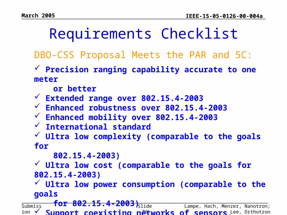
Requirements ChecklistDBO-CSS Proposal Meets the PAR and 5C: Precision ranging capability accurate to one meter or better Extended range over 802.15.4-2003 Enhanced robustness over 802.15.4-2003 Enhanced mobility over 802.15.4-2003 International standard Ultra low complexity (comparable to the goals for 802.15.4-2003) Ultra low cost (comparable to the goals for 802.15.4-2003) Ultra low power consumption (comparable to the goals for 802.15.4-2003) Support coexisting networks of sensors, controllers, logistic and peripheral devices in multiple compliant co-located systems.
March 2005
Lampe, Hach, Menzer, Nanotron; Lee, OrthotronSlide 77
IEEE-15-05-0126-00-004a
Submission
Summary
March 2005
Lampe, Hach, Menzer, Nanotron; Lee, OrthotronSlide 78
IEEE-15-05-0126-00-004a
Submission
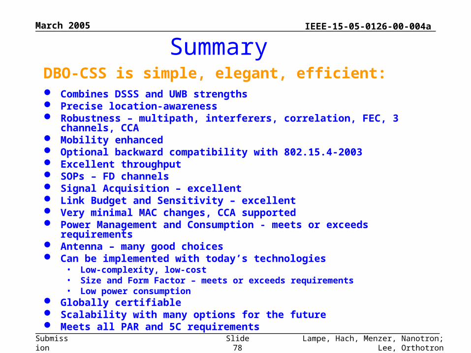
SummaryDBO-CSS is simple, elegant, efficient: Combines DSSS and UWB strengths Precise location-awareness Robustness – multipath, interferers, correlation, FEC, 3 channels, CCA Mobility enhanced Optional backward compatibility with 802.15.4-2003 Excellent throughput SOPs – FD channels Signal Acquisition – excellent Link Budget and Sensitivity – excellent Very minimal MAC changes, CCA supported Power Management and Consumption - meets or exceeds requirements Antenna – many good choices Can be implemented with today’s technologies
• Low-complexity, low-cost• Size and Form Factor – meets or exceeds requirements• Low power consumption
Globally certifiable Scalability with many options for the future Meets all PAR and 5C requirements