Embed Size (px)
Citation preview

Abstract
This document describes IEEE 802.11 Wireless Local Area Network (WLAN) Standard. It describes IEEE802.11 MAC Layer in detail and It briefly mentions IEEE 802.11a, IEEE 802.11b physical layer standard andIEEE 802.11e MAC layer standard.
Contents
1 Overview 41.1 Introduction . . . . . . . . . . . . . . . . . . . . . . . . . . . . . . . . . . . . . . . . . . . . . . . 4
1.1.1 Goals . . . . . . . . . . . . . . . . . . . . . . . . . . . . . . . . . . . . . . . . . . . . . . 41.1.2 Architecture . . . . . . . . . . . . . . . . . . . . . . . . . . . . . . . . . . . . . . . . . . 5
2 Medium Access Control 102.1 MAC Functionality . . . . . . . . . . . . . . . . . . . . . . . . . . . . . . . . . . . . . . . . . . . 102.2 MAC Frame Exchange Protocol . . . . . . . . . . . . . . . . . . . . . . . . . . . . . . . . . . . . 10
2.2.1 Dealing with Media . . . . . . . . . . . . . . . . . . . . . . . . . . . . . . . . . . . . . . 112.2.2 The Hidden Node Problem . . . . . . . . . . . . . . . . . . . . . . . . . . . . . . . . . . 112.2.3 Retry Counters . . . . . . . . . . . . . . . . . . . . . . . . . . . . . . . . . . . . . . . . . 122.2.4 Basic Access Mechanism . . . . . . . . . . . . . . . . . . . . . . . . . . . . . . . . . . . . 132.2.5 Timing Intervals . . . . . . . . . . . . . . . . . . . . . . . . . . . . . . . . . . . . . . . . 132.2.6 DCF Operation . . . . . . . . . . . . . . . . . . . . . . . . . . . . . . . . . . . . . . . . . 142.2.7 Centrally Controlled Access Mechanism . . . . . . . . . . . . . . . . . . . . . . . . . . . 142.2.8 Frame Types . . . . . . . . . . . . . . . . . . . . . . . . . . . . . . . . . . . . . . . . . . 162.2.9 Control Frame Subtypes . . . . . . . . . . . . . . . . . . . . . . . . . . . . . . . . . . . . 182.2.10 Data Frame Subtypes . . . . . . . . . . . . . . . . . . . . . . . . . . . . . . . . . . . . . 202.2.11 Management Frame Subtypes . . . . . . . . . . . . . . . . . . . . . . . . . . . . . . . . . 212.2.12 Components of the Management Frame Body . . . . . . . . . . . . . . . . . . . . . . . . 232.2.13 Other MAC Operations . . . . . . . . . . . . . . . . . . . . . . . . . . . . . . . . . . . . 26
3 MAC Management 283.1 Tools Available to Meet the Challenges . . . . . . . . . . . . . . . . . . . . . . . . . . . . . . . 28
3.1.1 Authentication . . . . . . . . . . . . . . . . . . . . . . . . . . . . . . . . . . . . . . . . . 283.1.2 Association . . . . . . . . . . . . . . . . . . . . . . . . . . . . . . . . . . . . . . . . . . . 293.1.3 Address Filtering . . . . . . . . . . . . . . . . . . . . . . . . . . . . . . . . . . . . . . . . 303.1.4 Privacy MAC Function . . . . . . . . . . . . . . . . . . . . . . . . . . . . . . . . . . . . 303.1.5 Power Management . . . . . . . . . . . . . . . . . . . . . . . . . . . . . . . . . . . . . . 30
1
3.1.6 Synchronization . . . . . . . . . . . . . . . . . . . . . . . . . . . . . . . . . . . . . . . . 323.2 Combining Management Tools . . . . . . . . . . . . . . . . . . . . . . . . . . . . . . . . . . . . 34
3.2.1 Combine Power Saving Periods with Scanning . . . . . . . . . . . . . . . . . . . . . . . . 343.2.2 Preauthentication . . . . . . . . . . . . . . . . . . . . . . . . . . . . . . . . . . . . . . . 35
4 MAC Management Information Base 364.1 Station Management Attributes . . . . . . . . . . . . . . . . . . . . . . . . . . . . . . . . . . . . 364.2 MAC Attributes . . . . . . . . . . . . . . . . . . . . . . . . . . . . . . . . . . . . . . . . . . . . 38
5 The Physical Layer 415.1 Physical Layer (PHY) Functionality . . . . . . . . . . . . . . . . . . . . . . . . . . . . . . . . . 415.2 Direct Sequence Spread Spectrum (DSSS) PHY . . . . . . . . . . . . . . . . . . . . . . . . . . . 41
5.2.1 DSSS PLCP Sublayer . . . . . . . . . . . . . . . . . . . . . . . . . . . . . . . . . . . . . 415.2.2 Data Scrambling . . . . . . . . . . . . . . . . . . . . . . . . . . . . . . . . . . . . . . . . 435.2.3 DSSS Modulation . . . . . . . . . . . . . . . . . . . . . . . . . . . . . . . . . . . . . . . 445.2.4 Barker Spreading Method . . . . . . . . . . . . . . . . . . . . . . . . . . . . . . . . . . . 445.2.5 DSSS Operating Channels and Transmit Power Requirements . . . . . . . . . . . . . . . 44
5.3 The Frequency Hopping Spread Spectrum (FHSS) PHY . . . . . . . . . . . . . . . . . . . . . . 455.3.1 FHSS PLCP Sublayer . . . . . . . . . . . . . . . . . . . . . . . . . . . . . . . . . . . . . 455.3.2 PSDU Data Whitening . . . . . . . . . . . . . . . . . . . . . . . . . . . . . . . . . . . . 475.3.3 FHSS Modulation . . . . . . . . . . . . . . . . . . . . . . . . . . . . . . . . . . . . . . . 475.3.4 FHSS Channel Hopping . . . . . . . . . . . . . . . . . . . . . . . . . . . . . . . . . . . . 48
5.4 Infrared (IR) PHY . . . . . . . . . . . . . . . . . . . . . . . . . . . . . . . . . . . . . . . . . . . 485.4.1 IR PLCP Sublayer . . . . . . . . . . . . . . . . . . . . . . . . . . . . . . . . . . . . . . . 485.4.2 IR PHY Modulation Method . . . . . . . . . . . . . . . . . . . . . . . . . . . . . . . . . 49
5.5 Geographic Regulatory Bodies . . . . . . . . . . . . . . . . . . . . . . . . . . . . . . . . . . . . 50
6 Physical Layer Extensions to IEEE 802.11 516.1 IEEE 802.11a - The OFDM Physical Layer . . . . . . . . . . . . . . . . . . . . . . . . . . . . . 51
6.1.1 OFDM PLCP Sublayer . . . . . . . . . . . . . . . . . . . . . . . . . . . . . . . . . . . . 516.1.2 Data Scrambler . . . . . . . . . . . . . . . . . . . . . . . . . . . . . . . . . . . . . . . . . 526.1.3 Convolutional Encoding . . . . . . . . . . . . . . . . . . . . . . . . . . . . . . . . . . . . 536.1.4 OFDM Modulation . . . . . . . . . . . . . . . . . . . . . . . . . . . . . . . . . . . . . . . 536.1.5 OFDM Operating Channels and Transmit Power Requirements . . . . . . . . . . . . . . 536.1.6 Geographic Regulatory Bodies . . . . . . . . . . . . . . . . . . . . . . . . . . . . . . . . 53
6.2 IEEE 802.11b-2.4 High Rate DSSS PHY . . . . . . . . . . . . . . . . . . . . . . . . . . . . . . . 546.2.1 HR/DSSS PHY PLCP Sublayer . . . . . . . . . . . . . . . . . . . . . . . . . . . . . . . 546.2.2 High Rate Data Scrambling . . . . . . . . . . . . . . . . . . . . . . . . . . . . . . . . . . 556.2.3 IEEE 802.11 High Rate Operating Channels . . . . . . . . . . . . . . . . . . . . . . . . . 556.2.4 IEEE 802.11 DSSS High Rate Modulation and Data Rates . . . . . . . . . . . . . . . . 55
2
3
6.2.5 Complementary Code Keying (CCK) Modulation . . . . . . . . . . . . . . . . . . . . . . 566.2.6 DSSS Packet Binary Convolutional Coding . . . . . . . . . . . . . . . . . . . . . . . . . 566.2.7 Frequency Hopped Spread Spectrum (FHSS)Inter operability . . . . . . . . . . . . . . . 56
7 System Design Considerations for IEEE 802.11 WLANs 577.1 The Medium . . . . . . . . . . . . . . . . . . . . . . . . . . . . . . . . . . . . . . . . . . . . . . 577.2 Multipath . . . . . . . . . . . . . . . . . . . . . . . . . . . . . . . . . . . . . . . . . . . . . . . . 577.3 Multipath Channel Model . . . . . . . . . . . . . . . . . . . . . . . . . . . . . . . . . . . . . . . 587.4 Path Loss in a WLAN System . . . . . . . . . . . . . . . . . . . . . . . . . . . . . . . . . . . . . 587.5 Multipath Fading . . . . . . . . . . . . . . . . . . . . . . . . . . . . . . . . . . . . . . . . . . . . 597.6 Es/No vs BER Performance . . . . . . . . . . . . . . . . . . . . . . . . . . . . . . . . . . . . . . 597.7 Data Rage vs Aggregate Throughput . . . . . . . . . . . . . . . . . . . . . . . . . . . . . . . . . 597.8 WLAN Installation and Site Survey . . . . . . . . . . . . . . . . . . . . . . . . . . . . . . . . . 597.9 Interference in the 2.4 GHz Frequency Band . . . . . . . . . . . . . . . . . . . . . . . . . . . . . 607.10 Antenna Diversity . . . . . . . . . . . . . . . . . . . . . . . . . . . . . . . . . . . . . . . . . . . 60
8 IEEE 802.11 PROTOCOLS 628.1 Overview of IEEE 802.11 Standards . . . . . . . . . . . . . . . . . . . . . . . . . . . . . . . . . 628.2 IEEE 802.11E MAC PROTOCOL . . . . . . . . . . . . . . . . . . . . . . . . . . . . . . . . . . 64
8.2.1 Enhanced Distribution Coordination Function . . . . . . . . . . . . . . . . . . . . . . . . 648.2.2 Hybrid Coordination Function . . . . . . . . . . . . . . . . . . . . . . . . . . . . . . . . 66
Chapter 1
Overview
1.1 Introduction
• In 1997, the IEEE adopted the first standard for WLANs and revised in 1999.
• IEEE defines a MAC sublayer, MAC management protocols and services, and three physical (PHY)layers.
• PHY Layers:
1. IR at baseband with 1-2 Mbps,
2. FHSS at 2.4GHz with 1-2 Mbps,
3. DSSS at DSSS with 1-2 Mbps.
• IEEE 802.11a ; PHY Layer - OFDM at UNII bands with 54 Mbps
• IEEE 802.11b ; PHY Layer - DSSS at 2.4 GHz with 11Mbps
1.1.1 Goals
• to deliver services previously found only in wired networks.
• high throughput
• highly reliable data delivery
• continuous network connection.
4
1.1.2 Architecture
Architecture is designed to support a network where mobile station is responsible for the decision making.Advantages are
• very tolerant of faults in all of the WLAN equipment.
• eliminates any possible bottlenecks a centralized architecture would introduce.
Architecture has power-saving modes of operation built into the protocol to prolong the battery life ofmobile equipment without losing network connectivity.
Components
Station the component that connects to the wireless medium. Supported services are authentication, deau-thentication, privacy, and delivery of the data.
Basic Service Set A BSS is a set of stations that communicate with one another. A BSS does not generallyrefer to a particular area, due to the uncertainties of electromagnetic propagation. When all of thestations int the BSS are mobile stations and there is no connection to a wired network, the BSS iscalled independent BSS (IBSS). IBSS is typically short-lived network, with a small number of stations,that is created for a particular purpose. When a BSS includes an access point (AP), the BSS is calledinfrastructure BSS.
When there is a AP, If one mobile station in the BSS must communicate with another mobile station,the communication is sent first to the AP and then from the AP to the other mobile station. Thisconsume twice the bandwidth that the same communication. While this appears to be a significantcost, the benefits provided by the AP far outweigh this cost. One of them is, AP buffers the traffic ofmobile while that station is operating in a very low power state.
Extended Service Set (ESS) A ESS is a set of infrastructure BSSs, where the APs communicate amongthemselves to forward traffic from one BSS to another and to facilitate the movement of mobile stationsfrom one BSS to another. The APs perform this communication via an abstract medium called thedistribution system (DS). To network equipment outside of the ESS, the ESS and all of its mobilestations appears to be a single MAC-layer network where all stations are physically stationary. Thus,the ESS hides the mobility of the mobile stations from everything outside the ESS.
Distribution System the distribution system (DS) is the mechanism by which one AP communicates withanother to exchange frames for stations in their BSSs, forward frames to follow mobile stations fromone BSS to another, and exchange frames with wired network.
Services • Station Services: Authentication, De-authentication, privacy, delivery of data
• Distribution Services: Association, Disassociation, Reassociation, Distribution, Integration
5
Station Services Similar functions to those that are expected of a wired network. The wired network func-tion of physically connecting to the network cable is similar to the authentication and de-authenticationservices. Privacy is for data security. Data delivery is the reliable delivery of data frames from theMAC in one station to the MAC in one or more other station, with minimal duplication and minimalordering.
Distribution Services provide services necessary to allow mobile stations to roam freely within an ESSand allow an IEEE 802.11 WLAN to connect with the wired LAN infrastructure. A thin layer betweenMAC and LLC sublayer that are invoked to determine how to forward frames within the IEEE 802.11WLAN and also how to deliver frames from the IEEE 802.11 WLAN to network destinations outside ofthe WLAN.
• The association service makes a logical connection between a mobile station and an AP. It isnecessary for DS to know where and how to deliver data to the mobile station. the logical connectionis also necessary for the AP to accept data frames from the mobile station and to allocate resourcesto support the mobile station. The association service is invoked once, when the mobile stationenters the WLAN for the first time, after the application of power or when rediscovering the WLANafter being out of touch for a time.
• The reassociation service includes information about the AP with which a mobile station has beenpreviously associated. Mobile station uses repeatedly as it moves in ESS and by using reassocia-tion service, a mobile station provides information to the AP with which the mobile station waspreviously associated, to obtain frames.
• The disassociation service is used to force a mobile station to associate or to inform mobile stationAP is no longer available. A mobile may also use the disassociation service when it no longerrequire the services of the AP.
• An AP to determine how to deliver the frames it receives uses the distribution service. AP invokethe distribution service to determine if the frame should be sent back into its own BSS, for deliveryto a mobile station that is associated with the AP, or if the frame should be sent into the DS fordelivery to another mobile station associated with a different AP or to a network destination.
• The integration service connects the IEEE 802.11 WLAN to other LANs, The integration servicetranslates IEEE 802.11 frames to frames that may traverse another network, and vice versa.
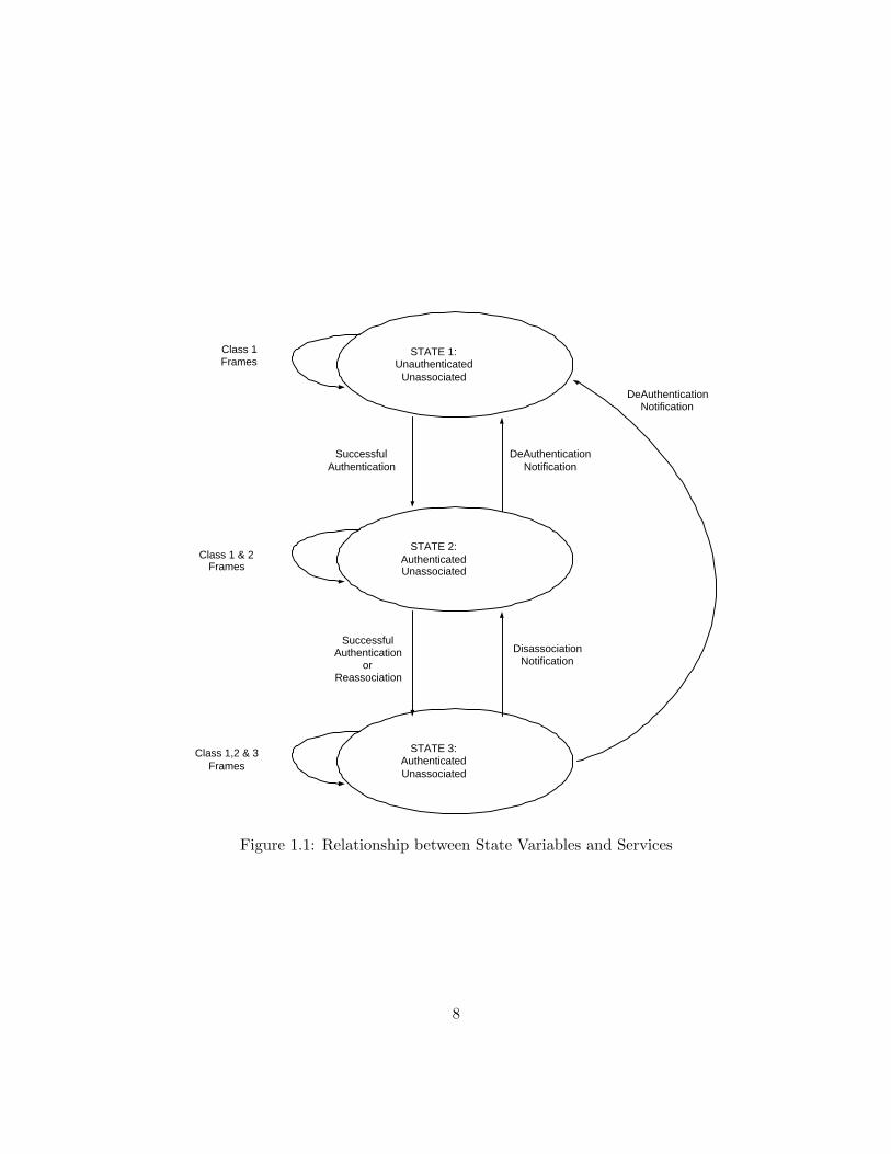
Interaction between Some Services The IEEE 802.11 standard states that each station must maintaintwo variables that are dependent on the authentication, de-authentication services and the association,reassociation, disassociation services. The variables are authentication state and association state andused in a simple state machine that determines the order in which certain services must be invoked andwhen a station may begin using the data delivery service. A station may be authenticated with manydifferent stations simultaneously. However, a station may be associated with only one other station ata time.
6
In state 1, the station may use a very limited number of frame types. This frames are to find anIEEE 802.11 WLAN, an ESS, and its APs, to complete the required frame handshake protocols, and toimplement the authentication service. If a station is part of an IBSS, it is allowed to implement the dataservice in state 1. In state2, additional frame types are allowed to provide the capability for a stationin state 2 to implement the association, reassociation, and disassociation services. In state 3, all frametypes are allowed and the station may use the data delivery service. A station must react to frames itreceives in each of the states, even those that are disallowed for a particular state. A station will send adeauthentication notification to any station with which it is not authenticated if it receives frames thatare not allowed in state 1. A station will send a disassociation notification to any station with which itis authenticated, but not associated, if it receives frames not allowed in state 2. These notifications willforce the station that sent the disallowed frames to make a transition to the proper state in the statediagram and allow it to proceeed properly toward state 3.
7
STATE 1: Unauthenticated
Unassociated
STATE 2: Authenticated Unassociated
STATE 3: Authenticated Unassociated
DeAuthentication Notification
Successful Authentication
Successful Authentication
or Reassociation
Disassociation Notification
Class 1 Frames
Class 1 & 2 Frames
Class 1,2 & 3 Frames
DeAuthentication Notification
Figure 1.1: Relationship between State Variables and Services
8
AP1 AP2
AP3
a
b
c e
f
d
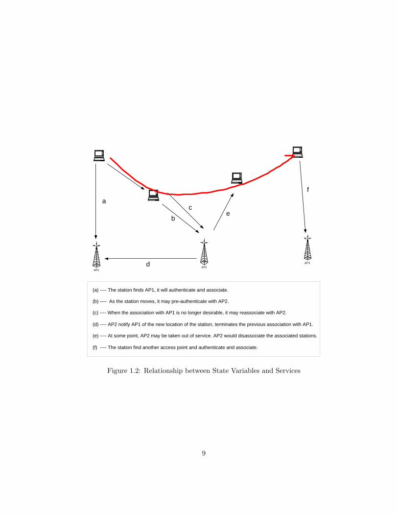
(a) ---- The station finds AP1, it will authenticate and associate.
(b) ---- As the station moves, it may pre-authenticate with AP2.
(c) ---- When the association with AP1 is no longer desirable, it may reassociate with AP2.
(d) ---- AP2 notify AP1 of the new location of the station, terminates the previous association with AP1.
(e) ---- At some point, AP2 may be taken out of service. AP2 would disassociate the associated stations.
(f) ---- The station find another access point and authenticate and associate.
Figure 1.2: Relationship between State Variables and Services
9
Chapter 2
Medium Access Control
MAC protocol supplies the functionality required to provide a reliable delivery mechanism for user data overnoisy, unreliable wireless media.
2.1 MAC Functionality
• reliable data delivery
• fairly control access to the shared wireless medium.
• protect the data that it delivers.
2.2 MAC Frame Exchange Protocol
• noisy and unreliable medium
• frame exchange protocol
• adds overhead to IEEE 802.3
• hidden node problem
• requires participation of all stations.
• every station reacts to every frame it receives.
10
2.2.1 Dealing with Media
The minimal MAC frame exchange protocol consists of two frames, a frame sent from the source to thedestination and an acknowledgment from the destination that the frame was received correctly. if the sourcedoes not get acknowledgement, it tries to transmit according to the basic access mechanism described below.This reduces the inherent error rate of the medium, at the expense of additional bandwidth consumptionwithout needing higher layer protocols. Since higher layer timeouts are often measured in seconds, it is muchmore efficient to deal with this issue at the MAC layer.
2.2.2 The Hidden Node Problem
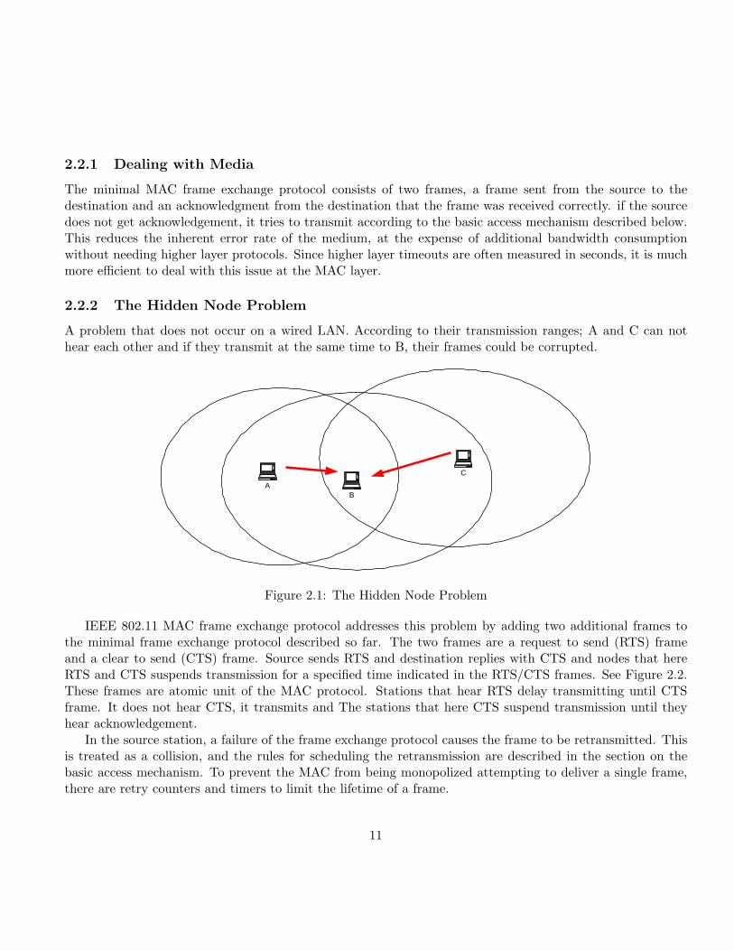
A problem that does not occur on a wired LAN. According to their transmission ranges; A and C can nothear each other and if they transmit at the same time to B, their frames could be corrupted.
A B
C
Figure 2.1: The Hidden Node Problem
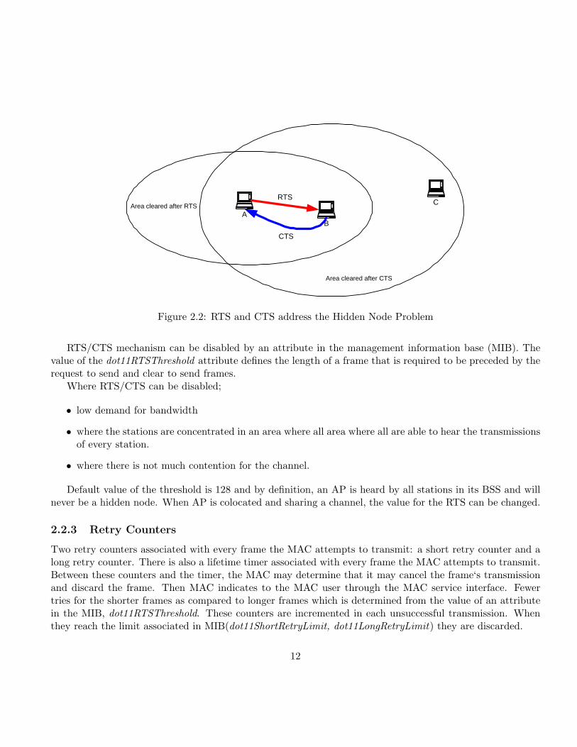
IEEE 802.11 MAC frame exchange protocol addresses this problem by adding two additional frames tothe minimal frame exchange protocol described so far. The two frames are a request to send (RTS) frameand a clear to send (CTS) frame. Source sends RTS and destination replies with CTS and nodes that hereRTS and CTS suspends transmission for a specified time indicated in the RTS/CTS frames. See Figure 2.2.These frames are atomic unit of the MAC protocol. Stations that hear RTS delay transmitting until CTSframe. It does not hear CTS, it transmits and The stations that here CTS suspend transmission until theyhear acknowledgement.
In the source station, a failure of the frame exchange protocol causes the frame to be retransmitted. Thisis treated as a collision, and the rules for scheduling the retransmission are described in the section on thebasic access mechanism. To prevent the MAC from being monopolized attempting to deliver a single frame,there are retry counters and timers to limit the lifetime of a frame.
11
A B
C RTS
CTS
Area cleared after RTS
Area cleared after CTS
Figure 2.2: RTS and CTS address the Hidden Node Problem
RTS/CTS mechanism can be disabled by an attribute in the management information base (MIB). Thevalue of the dot11RTSThreshold attribute defines the length of a frame that is required to be preceded by therequest to send and clear to send frames.
Where RTS/CTS can be disabled;
• low demand for bandwidth
• where the stations are concentrated in an area where all area where all are able to hear the transmissionsof every station.
• where there is not much contention for the channel.
Default value of the threshold is 128 and by definition, an AP is heard by all stations in its BSS and willnever be a hidden node. When AP is colocated and sharing a channel, the value for the RTS can be changed.
2.2.3 Retry Counters
Two retry counters associated with every frame the MAC attempts to transmit: a short retry counter and along retry counter. There is also a lifetime timer associated with every frame the MAC attempts to transmit.Between these counters and the timer, the MAC may determine that it may cancel the frame‘s transmissionand discard the frame. Then MAC indicates to the MAC user through the MAC service interface. Fewertries for the shorter frames as compared to longer frames which is determined from the value of an attributein the MIB, dot11RTSThreshold. These counters are incremented in each unsuccessful transmission. Whenthey reach the limit associated in MIB(dot11ShortRetryLimit, dot11LongRetryLimit) they are discarded.
12
2.2.4 Basic Access Mechanism
The basic access mechanism is carrier sense multiple access with collision avoidance (CSMA/CA) with binaryexponential backoff similar to IEEE 802.3, with some significant exceptions. CSMA/CA is a “listen beforetalk” (LBT) access mechanism. When there is a transmission in the medium, the station will not begin its owntransmission. This is the CSMA portion of the access mechanism. If there is a collision and the transmissioncorrupted, the operation of the access mechanism works to ensure the correct reception of the informationtransmitted on the wireless medium.
As IEEE 802.11 implements this access mechanism, when a station listens to the medium before beginningits own transmission and detects an existing transmission in progress, the listening station enters a wait perioddetermined by the binary exponential backoff algorithm. It will also increment the appropriate retry counterassociated with the frame. The binary exponential backoff mechanism chooses a random number whichrepresents the amount of time that must elapse while there are not any transmissions, i.e., the medium is idlebefore the listening station may attempt to begin its transmission again. The random number resulting fromthis algorithm is uniformly distributed in a range, called the contention window, the size of which doubleswith every attempt to transmit that is deferred, until a maximum size is reached for the range. Once atransmission is successfully transmitted, the range is reduced to its minimum value for the next transmission.
It is extremely unusual for a wireless device to be able to receive and transmit simultaneously, the IEEE802.11 MAC uses collision avoidance rather than the collision detection of IEEE 802.3. It is also unusual forall wireless devices in LAN to be able to communicate directly with all other devices. For this reason, IEEE802.11 MAC implements a network allocation vector (NAV). The NAV is a value that indicates to a station theamount of time that remains before the medium will become available. Even if the medium does not appearto be carrying a transmission by the physical carrier sense, the station may avoid transmitting. The NAV,then, is a virtual carrier sensing mechanism. By combining the virtual carrier sensing mechanism with thephysical carrier sensing mechanism, the MAC implements the collision avoidance portion of the CSMA/CAaccess mechanism.
2.2.5 Timing Intervals
There are five timing intervals.
1. PHY determines: the short interframe space (SIFS)
2. PHY determines: the slot time.
3. the priority interframe space (PIFS),
4. the distributed interframe space (DIFS),
5. and the extended interframe space (EIFS).
The SIFS is the shortest interval, followed by the slot time which is slightly longer. The PIFS is equal toSIFS plus one slot time. The DIFS is equal to the SIFS plus two slot times. The EIFS is much larger than
13
any of the other intervals. It is used when a frame that contains errors is received by the MAC, allowingthe possibility for the MAC frame exchanges to complete correctly before another transmission is allowed.Through these five timing intervals, both the DCF and PCF are implemented.
2.2.6 DCF Operation
The basic 802.11 MAC protocol is the DCF based on CSMA. Stations deliver MAC Service Data Units(MSDUs). Stations deliver MSDUs of arbitrary lengths up to 2304 bytes, after detecting that there is noother transmission in progress on the channel. However, if two stations detect the channel as free at the sametime, a collision occurs. The 802.11 defines a Collision Avoidance (CA) mechanism to reduce the probabilityof such collisions. Before starting a transmission a station has to keep sensing the channel for an additionalrandom time after detecting the channel as being idle for a minimum duration called DIFS, which is 34 usfor the 802.11a PHY. Only if the channel remains idle for this additional random time period, the station isallowed to initiate its transmission.
1. when the MAC receives a request to transmit a frame, a check is made of the physical and virtual carriersense mechanisms.
2. if the medium is not in use for an interval of DIFS (or EIFS if the pre-received frame is contained errors),the MAC may begin transmission to the frame.
3. if the medium is in use during the DIFS interval, the MAC will select a backoff and increment the retrycounter.
4. The MAC will decrement the backoff value each time the medium is detected to be idle for an intervalof one slot time.
5. it there is a collision, the contention window is doubled, a new backoff interval is selected.
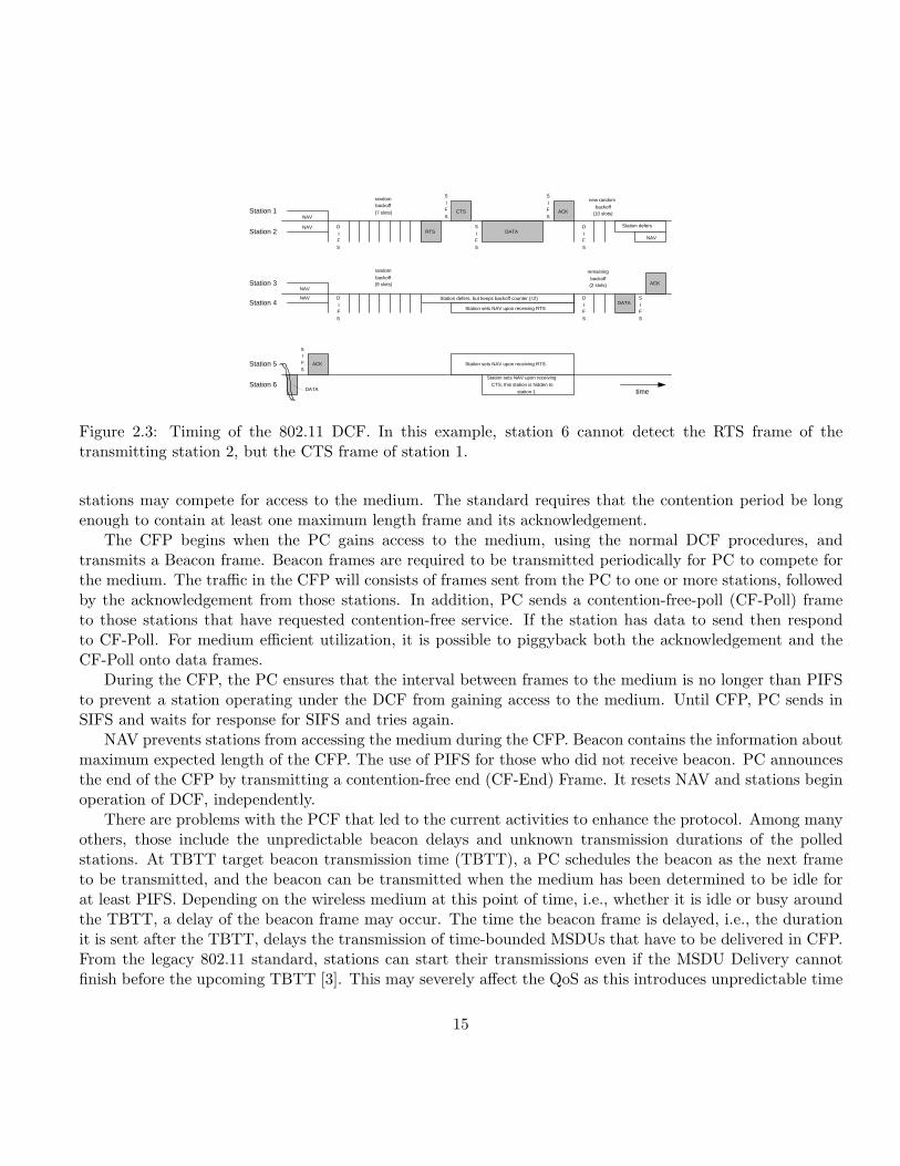
An example of a DCF operation is seen in Figure 2.3.
2.2.7 Centrally Controlled Access Mechanism
Uses a poll and response protocol to eliminate the possibility of contention for the medium. This accessmechanism is called PCF. A point coordinator (PC) controls the PCF. The PC is always located in an AP.Generally, the PCF operates by stations requesting that the PC register them on a polling list, and the PCthen regularly polls the stations for traffic while also delivering traffic to the stations. The PCF is built overthe DCF and both operate simultaneously. The PCF uses PIFS instead of DIFS. The PC begins a period ofoperation called the contention-free period (CFP), during which the PCF is operating. This period is calledcontention free because access to the medium is completely controlled by the PC and the DCF is preventedfrom gaining access to the medium. The CFP occurs periodically to provide a near-isochronous service tothe stations. The CFP also alternates with a contention period where the normal DCF rules operate and all
14
Station sets NAV upon receiving RTS
Station sets NAV upon receiving
CTS, this station is hidden to
station 1
Station 1 NAV
NAV
Station sets NAV upon receiving RTS
Station 6
Station 5
Station 4
Station 3
Station 2 RTS
S
I F
S
NAV
NAV
NAV
S
I F
S
S
I F
S
S
I F
S
S I F
S
D
I F
S
D
I F
S
D
I F
S
D
I F
S
random backoff
(7 slots)
new random
backoff (10 slots)
random
backoff (9 slots)
remaining
backoff (2 slots)
CTS
ACK
ACK
ACK
DATA
DATA
Station defers, but keeps backoff counter (=2)
Station defers
time DATA
Figure 2.3: Timing of the 802.11 DCF. In this example, station 6 cannot detect the RTS frame of thetransmitting station 2, but the CTS frame of station 1.
stations may compete for access to the medium. The standard requires that the contention period be longenough to contain at least one maximum length frame and its acknowledgement.
The CFP begins when the PC gains access to the medium, using the normal DCF procedures, andtransmits a Beacon frame. Beacon frames are required to be transmitted periodically for PC to compete forthe medium. The traffic in the CFP will consists of frames sent from the PC to one or more stations, followedby the acknowledgement from those stations. In addition, PC sends a contention-free-poll (CF-Poll) frameto those stations that have requested contention-free service. If the station has data to send then respondto CF-Poll. For medium efficient utilization, it is possible to piggyback both the acknowledgement and theCF-Poll onto data frames.
During the CFP, the PC ensures that the interval between frames to the medium is no longer than PIFSto prevent a station operating under the DCF from gaining access to the medium. Until CFP, PC sends inSIFS and waits for response for SIFS and tries again.
NAV prevents stations from accessing the medium during the CFP. Beacon contains the information aboutmaximum expected length of the CFP. The use of PIFS for those who did not receive beacon. PC announcesthe end of the CFP by transmitting a contention-free end (CF-End) Frame. It resets NAV and stations beginoperation of DCF, independently.
There are problems with the PCF that led to the current activities to enhance the protocol. Among manyothers, those include the unpredictable beacon delays and unknown transmission durations of the polledstations. At TBTT target beacon transmission time (TBTT), a PC schedules the beacon as the next frameto be transmitted, and the beacon can be transmitted when the medium has been determined to be idle forat least PIFS. Depending on the wireless medium at this point of time, i.e., whether it is idle or busy aroundthe TBTT, a delay of the beacon frame may occur. The time the beacon frame is delayed, i.e., the durationit is sent after the TBTT, delays the transmission of time-bounded MSDUs that have to be delivered in CFP.From the legacy 802.11 standard, stations can start their transmissions even if the MSDU Delivery cannotfinish before the upcoming TBTT [3]. This may severely affect the QoS as this introduces unpredictable time
15
Station 3 sets NAV at TBTT
Station 4 is hidden to the PC, it does not set its NAV, This station
should not be part of the BSS coordinated by the PC (station 1)
Station sets NAV
upon receiving RTS
NAV
reset
Listen before talk polling only
S
I F
S
P
I F
S
S
I F
S
CF-
ACK
CF- Poll
Station defers, but
keeps backoff counter (=2)
time
Station sets
NAV upon receiving RTS
S
I F
S
CF- END
S
I F
S
S
I F
S
Station 4
Station 3
Station 2
Station 1
S I
F
S ACK
DCF data transmission during
Contention Period
TBTT CP
Listen before
talk
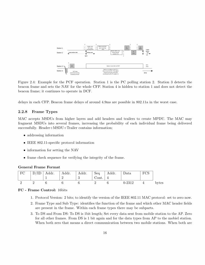
Figure 2.4: Example for the PCF operation. Station 1 is the PC polling station 2. Station 3 detects thebeacon frame and sets the NAV for the whole CFP. Station 4 is hidden to station 1 and does not detect thebeacon frame; it continues to operate in DCF.
delays in each CFP. Beacon frame delays of around 4.9ms are possible in 802.11a in the worst case.
2.2.8 Frame Types
MAC accepts MSDUs from higher layers and add headers and trailers to create MPDU. The MAC mayfragment MSDUs into several frames, increasing the probability of each individual frame being deliveredsuccessfully. Header+MSDU+Trailer contains information;
• addressing information
• IEEE 802.11-specific protocol information
• information for setting the NAV
• frame check sequence for verifying the integrity of the frame.
General Frame Format
FC D/ID Addr.1
Addr.2
Addr.3
SeqCont.
Addr.4
Data FCS
2 2 6 6 6 2 6 0-2312 4 bytes
FC - Frame Control: 16bits
1. Protocol Version: 2 bits; to identify the version of the IEEE 802.11 MAC protocol: set to zero now.
2. Frame Type and Sub Type: identifies the function of the frame and which other MAC header fieldsare present in the frame. Within each frame types there may be subparts.
3. To DS and From DS: To DS is 1bit length; Set every data sent from mobile station to the AP. Zerofor all other frames. From DS is 1 bit again and for the data types from AP to the mobiel station.When both zero that means a direct communication between two mobile stations. When both are
16
on, for special case where an IEEE 802.11 WLAN is being used as the DS refeered as wireless DS.The frame is being sent from one AP to another, over the wireless medium.
4. More Fragments Subfield: 1bit; indicates that this frame is not the last fragment of a data ormanagement frame.
5. Retry Subfield: 1bit; when zero, the frame is transmitted for the first time, otherwise it is aretransmission.
6. Power Management Subfield: 1bit;mobile station announces its power management state; 0 meansstation is in active mode and 1 means the station will enter the power management mode. Thesubfield should be same during the frame exchange in order for the mobile to change its powermanagement mode. Frame exchange is 2or 4 way frame handshake including the ACK.
7. More Data Subfield: 1bit; AP uses to indicate to a mobile station that there is at least one framebuffered at the AP for the mobile station. Mobile polled by the PC during a CFP also may use thissubfield to indicate to the PC that there is at least one more frame buffered at the mobile stationto be sent to the PC. In multicast , AP may also set to indicate there are more multicast frames.
8. WEP Subfield: 1bit; 1 indicates that the frame body of MAC frame has been encrypted usingWEP algorithm.(only data and management frames os subtype authentication)
9. Order Subfield: 1bit; indicates that the content of the data frame was provided to the MAC witha request for strictly ordered service. provides information to the AP and DS to allow this serviceto be delivered.
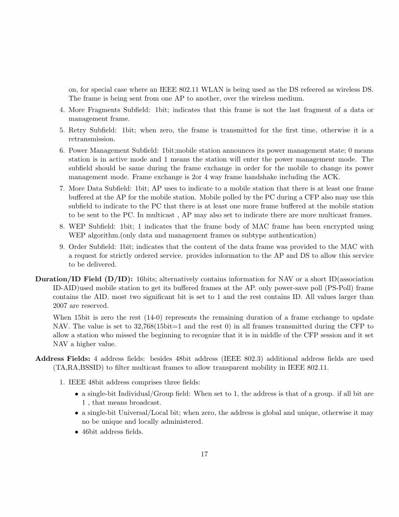
Duration/ID Field (D/ID): 16bits; alternatively contains information for NAV or a short ID(associationID-AID)used mobile station to get its buffered frames at the AP. only power-save poll (PS-Poll) framecontains the AID. most two significant bit is set to 1 and the rest contains ID. All values larger than2007 are reserved.
When 15bit is zero the rest (14-0) represents the remaining duration of a frame exchange to updateNAV. The value is set to 32,768(15bit=1 and the rest 0) in all frames transmitted during the CFP toallow a station who missed the beginning to recognize that it is in middle of the CFP session and it setNAV a higher value.
Address Fields: 4 address fields: besides 48bit address (IEEE 802.3) additional address fields are used(TA,RA,BSSID) to filter multicast frames to allow transparent mobility in IEEE 802.11.
1. IEEE 48bit address comprises three fields:
• a single-bit Individual/Group field: When set to 1, the address is that of a group. if all bit are1 , that means broadcast.
• a single-bit Universal/Local bit; when zero, the address is global and unique, otherwise it mayno be unique and locally administered.
• 46bit address fields.
17
2. BSS Identifier (BSSID): unique identifier for a particular BSS. In an infrastructure BSSID it is theMAC address of the AP. In IBSS, it is random and locally administered by the starting station.This also give uniqueness. In the probe request frame and group address can be used.
3. Transmitter Address (TA): MAC address of the station that transmit the frame to the wirelessmedium. Always an individual address.
4. Receiver Address (RA): to which the frame is sent over wireless medium. Individual or Group.
5. Source Address (SA): MAC address of the station who originated the frame. Always individualaddress. May not match TA because of the indirection performed by DS of an IEEE 802.11 WLAN.SA field is considered by higher layers.
6. Destination Address (DA): Final destination . Individual or Group. May not match RA becauseof the indirection.
Sequence Control Field: 16bit: 4bit fragment number and 12bit sequence number. Allow receiving stationto eliminate duplicate received frames.
1. Sequence Number Subfield: 12bit; Each MSDU has a sequence number and it is constant. Sequen-tially incremented for the following MSDUs.
2. Fragment Number Subfield: 4bits; Assigned to each fragment of an MSDU. The firs fragment isassigned to zero and incremented sequentially.
Frame Body Field: contains the information specific to the particular data or management frames. Variablelength. As long as 2304bytes and when ecrypted 2312bytes. An application may sent 2048byte with256 byte upper layer headers.
Frame Check Sequence Field: 32 bits; CCITT CRC-32 polynomial:
G(x) = x32 + x26 + x23 + x22 + x16 + x12 + x11 + x10 + x8 + x7 + x5 + x4 + x2 + x + 1
The frame check sequence is an IEEE 802 LAN standards and generated in the same way as it is inIEEE 802.3.
2.2.9 Control Frame Subtypes
Request to Send 20bytes;
• Frame Control Field:
• Duration/ID field:
• RA-always individual address
• TA
18
• FCS
The purpose is to transmit the duration to stations in order for them to update their NAV to preventtransmissions from colliding with the data or management frame that is expected to follow. Durationinformation conveyed by this frame is a measure of the amount of time required to complete the four-wayframe exchange. Duration (ms)= CTS+Data or management frame+ ACK+ 2 SIFS
Clear to Send: 14bytes;
• Frame Control Field, Duration/ID Field
• RA, individual MAC address
• FCS
for updating the NAV. Duration (ms) =Data or management frame + ACK + 1 SIFS
Acknowledge: 14 bytes;
• Frame Control Field
• Duration/ID Field (ms): Duration is zero if the ACK is an acknowledgement. The value of theduration information is the time to transmit the subsequent data or management frame, an ACKframe, and two SIFS intervals, if the acknowledgement is of a data or management frame wherethe more fragments subfield of the frame control field is one.
• RA: individual address. RA is taken from the address 2 field of data, management or PS-Pollframe.
• FCS
The purpose of this frame is two-fold. First, the ACK frame transmits an acknowledgement to thesender of the immediately previous data, management, or PS-Poll frame that the frame was receivedcorrectly. Second, the ACK frame is used to transmit the duration of information for a fragment burstas in CTS.
Power Save Poll: 20 bytes;
• Frame Control Field
• Duration/ID Field: AID value given to the mobile station upon association with the BSS. when aPS-Poll frame will update its NAV with a value which is the length of time to transmit an ACKand SIFS interval this action for AP to send ACK.
• BSSID
• TA: MAC address of the mobile station that is sending the PS-Poll Frame.
• FCS
19
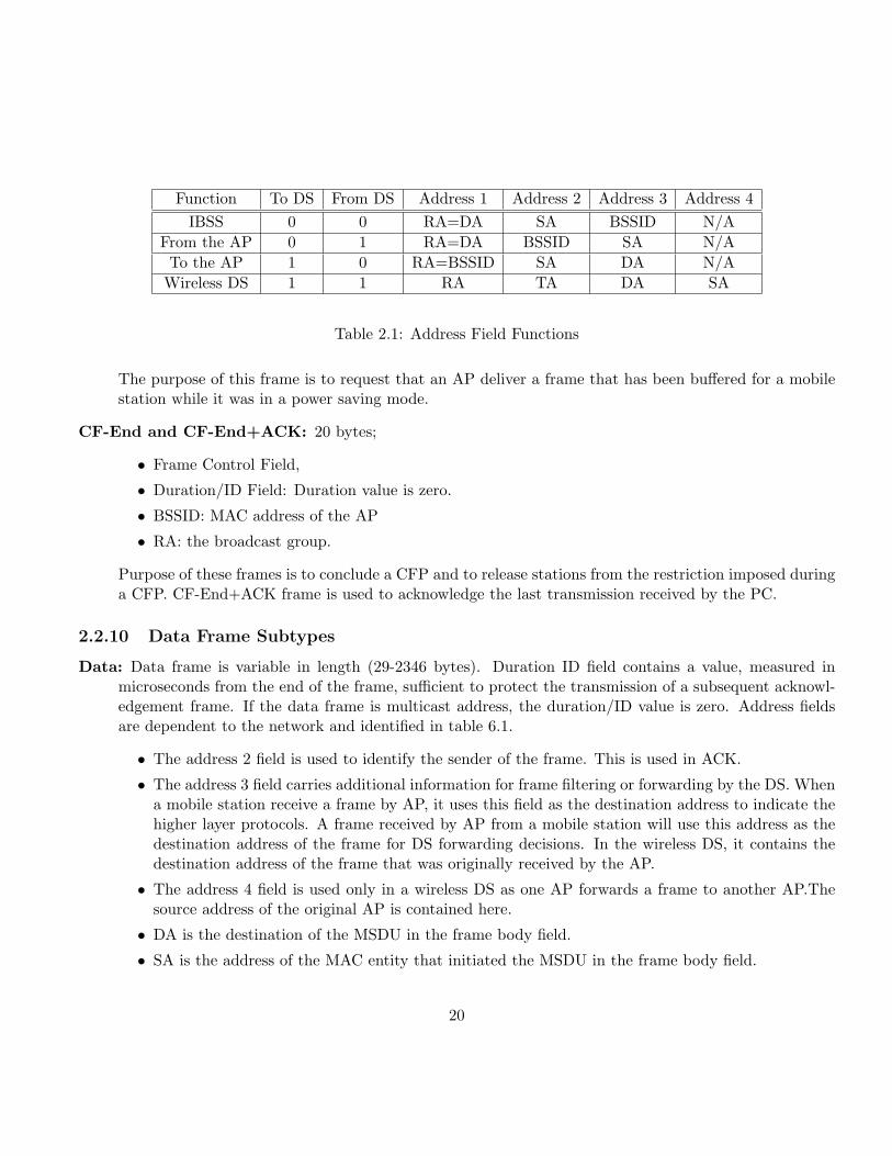
Function To DS From DS Address 1 Address 2 Address 3 Address 4IBSS 0 0 RA=DA SA BSSID N/A
From the AP 0 1 RA=DA BSSID SA N/ATo the AP 1 0 RA=BSSID SA DA N/A
Wireless DS 1 1 RA TA DA SA
Table 2.1: Address Field Functions
The purpose of this frame is to request that an AP deliver a frame that has been buffered for a mobilestation while it was in a power saving mode.
CF-End and CF-End+ACK: 20 bytes;
• Frame Control Field,
• Duration/ID Field: Duration value is zero.
• BSSID: MAC address of the AP
• RA: the broadcast group.
Purpose of these frames is to conclude a CFP and to release stations from the restriction imposed duringa CFP. CF-End+ACK frame is used to acknowledge the last transmission received by the PC.
2.2.10 Data Frame Subtypes
Data: Data frame is variable in length (29-2346 bytes). Duration ID field contains a value, measured inmicroseconds from the end of the frame, sufficient to protect the transmission of a subsequent acknowl-edgement frame. If the data frame is multicast address, the duration/ID value is zero. Address fieldsare dependent to the network and identified in table 6.1.
• The address 2 field is used to identify the sender of the frame. This is used in ACK.
• The address 3 field carries additional information for frame filtering or forwarding by the DS. Whena mobile station receive a frame by AP, it uses this field as the destination address to indicate thehigher layer protocols. A frame received by AP from a mobile station will use this address as thedestination address of the frame for DS forwarding decisions. In the wireless DS, it contains thedestination address of the frame that was originally received by the AP.
• The address 4 field is used only in a wireless DS as one AP forwards a frame to another AP.Thesource address of the original AP is contained here.
• DA is the destination of the MSDU in the frame body field.
• SA is the address of the MAC entity that initiated the MSDU in the frame body field.
20
• RA is the address of the station contained in the AP in the wireless DS that is next recipient.
• TA is the address of the station contained in the AP in the wireless DS that is transmitting theframe.
• BSSID is the address currently in use by the station contained in the AP if the station is AP or isassociated with an AP. Otherwise, BSSID is the BSSID of the IBSS.
Data+CF-ACK: Sent only during a CFP. Never used in IBSS. ACK is for previously received data frame,which may not be associated with the address of the destination of the current frame.
Data+CF-Poll: This frame is used only by PC during a CFP to deliver data to a mobile station andsimultaneously request that the mobile station send a data frame that it may have buffered, when thecurrent reception is completed.
Data+CF-ACK+CF-Poll: Combines the Data+CF-ACK and Data+CF-Poll frames into a single frameand used by the PC during a CFP.
Null Function (no data): This frame is a data frame with no frame body and used to allow a station thathas nothing to transmit to be able to complete the frame exchange necessary for changing its powermanagement state. The sole purpose for this frame is to carry the power management bit in the framecontrol field to the AP, when a station changes to a low power operating state.
CF-ACK (no data): Mobile station uses to acknowledge the PC during a CFP. ACK is more efficient sincethis frame is 29bytes long.
CF-Poll (no data): PC uses to request that a mobile station send a pending data frame during the CFP.
CF-ACK+CF-Poll (no data): Used by the PC and combines CF-ACK and CF-Poll .
2.2.11 Management Frame Subtypes
IEEE 802.11 is different from many of the other IEEE 802 standards because it includes very extensive man-agement capabilities defined at the MAC level. One of the four MAC frame types is dedicated to managementframes. There are 11 distinct management frame types. All management frames include:
• Frame Control,
• Duration,
• Address 1, 2, and 3,
• Sequence control,
• Framebody,
21
– Element ID
– Length
– Information (variable length)
• Frame check sequence (FCS) fields.
Beacon: It is used to identify a BSS. The Beacon frame also conveys information to mobile stations aboutframes that may be buffered during times of low power operation. The Beacon frame includes thefollowing fixed fields:
Timestamp: 64bits, contains the value of the station‘s synchronization timer at the time that theframe was transmitted.
Beacon Interval: 16-bit, The Beacon interval is the period, measured in “time units ” (TU) of 1024microseconds, of beacon transmissions.
Capability Information: 16-bit, it identifies the capabilities of the station.
The information elements in a Beacon frame are the service set identity (SSID), the supported rates, oneor more PHY parameter sets, an optional contention-free parameter set, an optional IBSS paramaterset, and an optional traffic indication map.
Probe Request and Response: Mobile station transmits to quickly locate an IEEE 802.11 WLAN. (witha particular SSID or any WLAN). It contains SSID and the supported rates. In the infrastructure BSS,the AP will always respond to probe requests and in IBSS, the mobile station that sent the latest Beaconwill respond.
The probe response contains nearly all the same information as a Beacon frame and includes the times-tamp, beacon interval, and capability information fixed fields. It also includes the SSID, supportedrates, one or more PHY parameter sets, the optional contention-free parameter set, and the optionalIBSS parameter set.
Authentication: The authentication frame is used to conduct a multiframe exchange between stations thatultimately results in the verification of the identity of each station to the other, within certain constraints.The authentication frame includes three fixed fields.
• the authentication algorithm number
• the authentication transaction sequence number
• the status code.
• status code.
Deauthentication: The station uses to notify another station of the termination of an authentication rela-tionship. The frame includes only a single fixed field, the reason code.
22
Association Request and Response: The mobile station request an association with a BSS and for thesuccess or failure of that request is returned to the mobile station by the response. The associationrequest frame includes two fixed fields, the capability information field and the listen interval. Thereare also two information elements in the association request, the SSID and the supported rates.
The association response frame includes three fixed fields: the capability information, the status code,and the association ID. There is one information element in the association response, the supportedrates.
Reassociation Request and Response: Mobile station that has been associated with a BSS and is nowassociating with another BSS with the same SSID uses the reassociation request that includes the sameinformation as an association request frame, with the addition of a current AP address fixed field. Thereassociation response frame is identical to the association response frame.
Disassociation: The station notifies another station of the termination of an association relationship. Theframe includes only a single fixed field, the reason code.
Announcement Traffic Indication Message: The announcement traffic indication message (ATIM) frameis used by mobile stations in an IBSS to notify other mobile stations in the IBSS that may have beenoperating in low power modes that the sender of the ATIM frame has traffic buffered and waiting to bedelivered to the station addressed in the ATIM frame.
2.2.12 Components of the Management Frame Body
Fixed Fields
Association ID (AID): 16-bit, It contains an arbitrary number assigned by the AP when a station asso-ciates with a BSS. The value is in the least significant 14 bits. The most 2 bit is set to 1.
Authentication Algorithm Number: 16-bit, it contains a number identifying the authentication algo-rithm to be used to complete an authentication transaction. 0 is for “open system” and 1 is for “ sharedkey” and the rest is reserved for future usage.
Authentication Transaction Sequence Number: 16-bit, It tracks the progress of an authentication trans-action. The number is increased sequentially with each authentication frame exchanged during thetransaction.
Beacon Interval: 16-bit, It indicates the typical amount of time that elapses between Beacon frame trans-missions. One TU (time units) is 1024 µs.
Capability Information: 16-bit,
• ESS
• IBSS
23
• CF pollable
• CF-Poll request
• privacy.
in IEEE 802.11b additionally three subfields are added.
• short preamble
• PBCC
• channel agility
The ESS and IBSS subfields are significant only in Beacon and probe response frames. AP sets ESSsubfield to 1 and the IBSS subfield to 0 and a mobile station in an IBSS always sets the ESS subfieldto 0 and the IBSS subfield to 1.
The CF pollable an CF-Poll request subfields are significant in Beacon, probe response, associationrequest, association response, reassociation request, and reassociation response frames. A mobile stationwill set these subfields in association request and reassociation request frames to indicate its contention-free capability and to request that it be placed on the polling list of the PC.
An AP will set these subfields in Beacon, probe response, association response, and reassociation re-sponse frames to indicate the capability of the PC.
The privacy subfield is transmitted by the AP in Beacon, probe response, association response, andreassociation response frames. In addition to indicating that the AP implements WEP, when set to 1,that means WEP is compulsory otherwise optional.
The short preamble subfield if transmitted by an AP or a mobile station in an IBSS in Beacon, proberesponse, association response, and reassociation response frames to indicate the availability of the shortpreamble option when using an IEEE 802.11b PHY. When set to 1, short preambles is allowed, when0, it is not allowed.
The packet binary convolutional coding (PBCC) subfield is transmitted by an AP or a mobile station inan IBSS in Beacon, probe response, association response, and reassociation response frames to indicatethe availability of the PBCC option when using an IEEE 802.11b PHY.
When a mobile station is not part of an IBSS, the PBCC subfield in association request and reassociationrequest frames indicates the capability of the station to send and receive the PBCC of IEEE 802.11b.
The channel agility subfield indicates that the station is using the channel agility option of IEEE 802.11b.
Current AP Address: 6 bytes, It holds the address of the AP with which a mobile station is currentlyassociated, when that mobile station is attempting to reassociate. If the reassociation is successful, thenew AP uses that AP address to contact and retrieve frames that may have been buffered there for themobile station.
24
Listen Interval: 16-bit, The listen interval is used by a mobile station to indicate to an AP how long themobile station may be in low power operating modes and unable to receive frames. The value is in unitsof the Beacon interval.
Reason Code: 16-bit, It indicates the reason for an unsolicited notification of disassociation or deauthenti-cation.
Status Code: 16-bit, It indicates the success or failure of a requested operation.
Timestamp: 64-bit, It is the value of the station‘s TSFTIMER at the time a frame was transmitted.
Information Elements: SSID, Supported rates, FH parameter set, DS parameter set, CF parameter set,TIM, IBSS parameter set, Reserved, Challenge text, Reserved for challenge text extension.
Service Set Identity (SSID) , max 32-bit,: This information carries the SSID of the IEEE 802.11 WLAN.When the length is zero, that means it is broadcasted. The broadcast identity is used in probe requestframes when the mobile station is attempting to discover all IEEE 802.11 WLANs in its vicinity.
Supported Rates: 1-8 bytes, Each byte represents a single rate where the lower 7 bits of the byte repre-senting the rate value, and the most significant bit indicating whether the rate is mandatory or not.
The supported rates element is transmitted in Beacon, probe response, association request, associationresponse, reassociation request, and reassociation response frames. If a station does not support all ofthe rates indicated to be mandatory, it may not associate with the BSS.
FH Parameter Set: 7 bytes, two byte element ID, length, the element contains the dwell time, hop set,hop pattern, and hop index. The FH parameter set element is present in Beacon and probe responseframes only if the PHY being used is the IEEE 802.11 FHSS PHY or the IEEE 802.11b PHY with thechannel agility option enabled.
DS Parameter Set: 3 bytes, It contains the element ID and length and current channel. This element ispresent in Beacon and probe response frames only if the IEEE 802.11 DSSS or IEEE 802.11b PHY isbeing used.
CF Parameter Set: 8 bytes, In addition to the element ID and length, this element contains the CFP count,CFP period, CFP max duration, and CFP duration remaining. This frame is present in Beacon andprobe response frames only if a PC is in operation in the BSS.
Traffic Indication Map: 6-256 bytes, This element carries information about frames that are buffered atthe AP for stations in power saving modes of operation.
• Element ID
• Length
• Delivery TIM (DTIM) count:
25
• DTIM period
• bitmap control
• partial virtual bitmap
The DTIM count and DTIM period are used to inform mobile stations when multicast frames that havebeen buffered at the AP will be delivered and how often that delivery will occur. DTIM count is aninteger value that counts down to zero. This value represents the number of Beacon frames that willoccur before the delivery of multicast frames. DTIM period is the number of Beacon frames betweenmulticast frame deliveries. The DTIM period has a significant effect on the maximum power savings astation may achieve.
IBSS Parameter Set: it occurs in beacon frames in an IBSS. It contains element ID, length and also theATIM window field. The announcement TIM (ATIM) window field is 16-bits long and indicates thelength of the ATIM window after each Beacon frame transmission in an IBSS. The length of the ATIMwindow is indicated in TU.
Challenge Text: 255 bytes, In addition to the element ID and length fields, this element carries one morefield, the challenge text.
2.2.13 Other MAC Operations
Fragmentation:
The IEEE 802.11 MAC can fragment its frames in an attempt to increase the probability that they will bedelivered without errors induced by the interference. When a frame is fragmented, the sequence control fieldof the frame header indicates the placement of the individual fragment among the set of fragments. The morefragments bit in the frame control field indicates whether the current fragment is the last fragment. Thefragments are transmitted in burst and they do not need to compete for the medium again since the mediumis reserved for the burst and duration is updated in every fragment and ACK.
Privacy:
The WLAN lacks even the minimal privacy provided by a wired LAN. The IEEE 802.11 Wired EquivalentPrivacy (WEP) mechanism provides protection at a level that is felt to be equivalent to that of a wired LAN.Data frames that are encrypted are sent with the WEP bit in the frame control field of the MAC header set.The receiver decrypt the frame and passes to the higher layer protocols.
Only the frame body is encrypted, this leaves the complete MAC header of the data frame, and the entireframe of other frame types, unencrypted and available to even the casual eavesdroppers.
The encryption algorithm used in IEEE 802.11 is RC4 developed by Ron Rivest of RSA Data Security,Inc. RC4 is a symmetric stream cipher that supports a variable key length (IEEE 802.11 chosen 40 bit keylength). It is symmetric since the same key and algorithm are used for both encryption and decryption. Unlike
26
a block chipper that processes a fixed number of bytes, a stream chipper is an algorithm that can process anarbitrary number of bytes.
The IEEE 802.11 standard describes the use of the RC4 algorithm and the key in WEP. However, keydistribution or key negotiation is not mentioned in the standard left to the individual manufacturers of IEEE802.11 equipment. Secure placement of keys int the individual stations is a discussion in IEEE 802.11 workinggroup.
WEP Details:
IEEE 802.11 provides two mechanisms to select a key for use when encrypting or decrypting a frame. Thefirst mechanism is a set of as many as four default keys. Default keys are intended to be shared by all stationsin a BSS or an ESS. The benefit of using a default key is that, once the station obtains the default keys, astation can communicate securely with all of the other stations in a BSS or ESS. The problem is they arewidely distributed to many stations and may be more likely to be revealed.
The second mechanism provided by IEEE 802.11 allows a station to establish a “key mapping” relationshipwith another station. Key mapping allows a station to create a key that is used with only one other station.
The dot11PrivacyInvoked attribute controls the use of WEP in a station. If it is set false, all framesare sent without encryption. Encryption for specific destinations may only be disabled if a key mappingrelationship exists with that destination.
A default key may be used to encrypt a frame only when a key mapping relationship does not exist betweenthe sending and receiving station. A key is available if its entry in the dot11WEPDefaultKeysTable is not null.If one or more default keys is available algorithm which is not defined in the standard chooses one of them.The WEP header and trailer are appended to the encrypted frame body, the default key used to encrypt theframe is indicated in the KeyID of the header portion along with the initialization vector, and the integritycheck value (ICV) in the trailer.
If key mapping relationship exists between source and destination stations, the “key mapping key,” the keyshared only by the source and destination stations, must be used to encrypt frames sent to that destination.The key is chosen dot11WEPKeyMappingsTable. The frame body is encrypted using the key mapping key, andthe WEP header and trailer are appended to the encrypted frame body, If the dot11WEPKeyMappingWEPOnentry for the destination is true.
Corresponding to the dot11PrivacyInvoked attribute controlling the sending of frames, the dot11ExcludeUnencryptedattribute controls the reception of encrypted frames. When it is false, all frames is accepted, whether theyare encrypted or not, otherwise only the encrypted ones will be received.
WEP associate with two counters. The dot11UndecryptableCount reflects the number of encrypted framesthat were received by the station that could not be decrypted. The dot11ICVErrorCount reflects the numberof frames that were received by a station for which a key was found that resulted in the calculated ICV valuenot matching the ICV received with the frame. These two counters should be monitored carefully when WEPis used in a WLAN. The dot11UndecrptableCount indicates that an attack to deny service may be in progress,if the counter is increasing rapidly. The dot11ICVErrorCount can indicate that an attack to determine a keyis in progress, if this counter is increasing rapidly.
27
Chapter 3
MAC Management
Because the media over which the IEEE 802.11 WLAN operate are not wires, the media are shared by otherusers that have no concept of data communication or sharing the media. An example of this type of user isthe common microwave oven. The microwave oven operates in the 2.4 GHz ISM band because one excitationfrequency of the water molecule lies in this band. Another user in this same band is the radio frequency ID(RFID) tag. RFID tags are usually small, cheap, unpowered devices that receive their power from a microwavebeam and then return a unique identifier. RFID tags are used to track retail inventory, identify rail cars, andmany other uses.
There are also other WLANs than IEEE 802.11 that share the media. This would be somewhat equivalentto attempting to run IEEE 802.3, IEEE 802.5, IEEE 802.12, and fiber distributed data interference (FDDI) onthe same twisted pair cable, simultaneously. These other WLAN users of the media are often uncoordinatedwith IEEE 802.11 and, in most cases, do not provide for any mechanism to share the media at all. Finally,there are other IEEE 802.11 WLANs sharing the media.
Since any one connect to a WLAN, it need to identify the stations connecting to the WLAN to identifythe stations and protect the data.
Another challenge is mobilitiy. Dealing with mobility while making all of the expected LAN servicesavailable is a problem to be solved by MAC management.
And power management is the final challenge, conserving the energy stored in the batteries to allow theequipment to operate for as long as possible must be built into the WLAN protocol and controlled by MACmanagement.
3.1 Tools Available to Meet the Challenges
3.1.1 Authentication
Authentication provides a mechanism for one station to prove its identity to another station in the WLAN.Authentication can be used between any two stations. However, it is most useful when used between a mobilestation and an AP in an infrastructure LAN. In this case, mobile station connect ESS and wired LAN behind
28
it through AP and full proof of the identity of the mobile station is necessary if the network is to be protectedfrom unauthorized users.
There are two authentication algorithm. “Open system authentication” is a guaranteed result of successafter two station introduce themselves to each other. No verification is needed.
The second authentication algorithm is the “shared key authentication algorithm”. This algorithm dependson both stations having a copy of a shared WEP key. This algorithm uses the WEP encryption option toencrypt and decrypt a “challenge text” as the proof that the stations share the same key. Beginning theauthentication process, station A sends its identity assertion to station B. Station B responds to the assertionwith an assertion of its own and a request to station A to prove its identity by correctly encrypting thechallenge text. Station A encrypts the challenge text using the normal WEP encryption rules, including useof default and key mapping keys, and sends the result back to station B. Station B decrypts the frame usingthe appropriate key and returns an authentication management frame to station A with the success of failureof the authentication indicated. If the authentication is successful, the standard says that each station isauthenticated to the other.
A station may authenticate with any number of other stations. Always mobile performs the encryptionoperation on the challenge text and AP somehow occupied in a more privileged position. This leaves theIEEE 802.11 WLAN open to some not so subtle security problems. In particular, a rogue AP could adoptthe SSID of the ESS and announce its presence through the normal beaconing process. A rogue could thensimply complete normal frame handshake procedures and the mobile stations would be the victims of a denialof service attack. A more active rogue could use more subtle means to attempt to gain access to the contentof higher layer protocol frames containing user names, passwords, and other sensitive data. If the data isencrypted using WEP, it is highly unlikely that the rogue could successfully decrypt the information.
3.1.2 Association
Association is the mechanism through which IEEE 802.11 provides transparent mobility to stations. Associ-ation may only be accomplished after a successful authentication has been completed.
When a mobile station requests to be connected to the WLAN, it sends an association request to anAP. The association request includes information on the capabilities of the station, such as the data ratesit supports, the high rate PHY options it supports, its contention-free capabilities, its support of WEP, andany request for contention-free services. The association request also includes information about the length oftime that the station may be in a low power operating mode. The policies and algorithms used by the AP tomake the decision of accepting the association request of the mobile station are not described in the standard.Some things that may be considered are supporting all of the required data rates and PHY options, requiringcontention-free services beyond the ability of the AP to support, long periods in low power operation thatrequire excessive buffer commitments from the AP, and the number of stations currently associated. Becausethe standard does not specify what information may be considered by the AP when deciding to grant anassociation, information not local to the AP may also be used, such as load balancing factors and availabilityof other APs nearby. When the AP responds to the mobile station with an association response, the responseincludes a status indication. The status indication provides the mobile station with the success or failure of
29
the association request. If the request fails, the reason for that failure is in the status indication.Once a station is associated, the AP is responsible for forwarding data frames from the mobile station
toward their destination. If the destination is in the same BSS as the mobile station, AP will simply transmitthe data frame to the BSS. If the destination of a data frame is outside the BSS, the AP will send the frameinto the DS. If the destination is in another BSS, the AP sends the frame to the AP of the other BSS, whereit will be forwarded to the mobile station. If the destination of the frame is entirely outside the ESS, the APwill forward the frame to the portal, the exit from the DS to the rest of the network. A portal is simply atransfer point between the wired LAN and the ESS, where frames logically enter the ESS. A portal may be anAP, a bridge, or a router. Because IEEE 802.11 is one of the family of IEEE 802 standards, an IEEE 802.11frame must be translated from the IEEE 802.11 format to the format of the other LAN. This translationshould be done according to IEEE Std 802.1h for bridging IEEE 802.11 to another LAN. The entire IEEE802.11 frame, including MAC header and FCS, should not be encapsulated within another MAC protocol.
Similarly, when a data frame is sent from outside the ESS to a mobile station, the portal must forwardthe frame to the correct AP, the one that has the mobile station associated in its BSS.
Once a station is successfully associated, it may begin exchanging data frames with the AP. When themobile loose contact with the AP, the mobile station must begin a new association in order to continueexchanging data frames. Because the DS must maintain information about the location of each mobilestation and because data frames may have been sent to an AP with which the mobile station no longer cancommunicate, a mobile station will use a reassociation request after its initial association. The AP that hasjust granted the reassociation normally communicates with the AP with which the station was last associatedto cause the termination of the old association.
3.1.3 Address Filtering
There may be more than one IEEE 802.11 WLAN operating in the same location and on the same mediumand channel. In this case, the receiver must examine more than the destination address to make correctreceive decisions. IEEE 802.11 incorporates at least three addresses in every data and management framethat may be received by a station. In addition to the destination address, these frames also include the BSSidentifier. A station must use both the destination address and the BSSID when making receive decisions,according to the standard.
3.1.4 Privacy MAC Function
The privacy function is provided by the WEP mechanism. Described in Chapter 2.
3.1.5 Power Management
Power Management in an Independent BSS
In an independent BSS (IBSS), power management is a fully distributed process, managed by the individualmobile stations. Power management comprises two parts: the functions of the station entering a low power
30
operating mode and the functions of the stations that desire to communicate with that station. For a stationto enter a low power operating state, a state where it has turned off the receiver and transmitter to conservepower, the station must successfully complete a data frame handshake with another station with the powermanagement bit set in the frame header. The IEEE 802.11 standard does not specify when a station mayenter or leave a low power operating state, only how the transition is to take place.
In the power saving state, the station must wake up to receive every Beacon transmission. The stationmust also stay awake for a period of time after each Beacon, called the announcement or ad hoc trafficindication message window (ATIM). The earliest the station may reenter the power saving state is at theconclusion of the ATIM window. The reason that a station must remain awake during the ATIM windowis that other stations that are attempting to send frames to it will announce those frames during the ATIMwindow. If the power saving station receives an ATIM frame, it must acknowledge that frame and remainawake until the end of the next ATIM window, following the next Beacon frame, in order to allow the otherstation to send its data frame. A station desiring to send a frame to another station in an IBSS, the standardrequires that the sending station estimate the power saving state of the intended destination. How the sendingstation creates its estimate is not described in the standard. If the station determines that the destination isin power saving state, then the station delays its transmission until it has received an acknowledgement of anATIM frame.
Multicast frames must also be announced by the sending station during the ATIM window before theymay be transmitted. The ATIM is sent to the same multicast address as the data frame that will be sentsubsequently. Because the ATIM is sent to a multicast address, no acknowledgement will be generated, noris one expected. Any stations that wish to receive the announced multicast data frame must stay awake untilthe end of the next ATIM window, after the next Beacon frame.
The power management mechanism puts a slightly greater burden on the sending station than on thereceiving station. Sending stations must send an announcement frame in addition to the data frame it desiresto deliver to the destination. Sending stations must buffer the frames to be sent to the power saving destinationuntil the destination awakens and acknowledges the ATIM. Each transmission of an ATIM consumes powerat the sending station. The receiving station must awaken for every Beacon and ATIM window, but need notmake any transmissions unless it receives an ATIM frame.
Power Management in an Infrastructure BSS
In an infrastructure BSS, the power management mechanism is centralized in the AP. This power managementmechanism allows much greater power savings for mobile stations than does the mechanism used in IBSSs.This is so because the AP assumes all of the burden of buffering data frames for power saving stations anddelivering them when the stations request, allowing the mobile stations to remain in their power saving statefor much longer periods.
Mobile station informs the AP, in its association request, of the number of beacon periods that the stationwill be in its power saving mode, to awaken at the expected time of a Beacon transmission to learn if thereare any data frames waiting, and to complete a successful frame handshake with the AP, while the powermanagement bit is set, to inform the AP when the station will enter the power saving mode.
31
A mobile station can achieve much deeper power savings than in the IBSS, because it is not requiredto awaken for every Beacon, nor to stay awake for any length of time after the Beacons for which it doesawaken. The mobile station must also awaken at times determined by the AP, when multicast frames are tobe delivered. This time is indicated in the Beacon frames as the delivery traffic indication map (DTIM).
The AP will buffer data and multicast frames if it has any stations associated that are in the power savingmode until a minimum time not less than the number of Beacon periods indicated in the mobile station‘sassociated request. The standard indicates an aging algorithm to discard buffered frames that are older thanit is required to preserve, though a specific algorithm is not described. AP indicate the frames buffered for apower saving station in the traffic indication map (TIM) sent with each Beacon frame. Each mobile stationhas an AID assigned in the association. When the bit in the TIM is set, there is at least one frame buffered forthe corresponding station. When the bit is clear, there are no frames buffered for the corresponding station.A special AID is dedicated to indicate the status of buffered multicast traffic and the AP will send the TIM,with every beacon.
If an AP has any buffered multicast frames, those frames are sent immediately after the Beacon announcingthe DTIM. If there is more than one multicast frame to be sent, the AP will indicate this fact by setting themore data bit in the frame control field of each multicast frame except for the last to be sent.
A mobile station requests delivery of buffered frames by sending a PS-Poll frame to the AP. The AP willrespond to each PS-Poll with a frame where more data bit is set. Mobile station is required to send a PS-Pollto the AP for each data frame it receives with the more data bit set.
An AP that is also a PC running a contention-free period (CFP) will use the CFP to deliver bufferedframes to stations that are CF Pollable. It may also use the CFP to deliver multicast frames after the DTIMis announced.
3.1.6 Synchronization
Synchronization is the process of the stations in a BSS getting in step with each other, so that reliablecommunication is possible. The MAC provides the synchronization mechanism to allow support of physical(PHY) layers that make use of frequency hopping or other time-based mechanisms where the parameters of thePHY layer change with time. The process involves beaconing, to announce the presence of a BSS, and scanning,to find a BSS. Once a BSS is found, a station joins the BSS. This process is entirely distributed, in bothindependent and infrastructure BSSs, and relies on a common timebase, provided by a timer synchronizationfunction (TSF).
Timer Synchronization in an Infrastructure BSS
In an infrastructure BSS, the AP is responsible for transmitting a Beacon frame periodically. The beaconperiod is included as part of the information in the Beacon frame in order to inform stations receiving theBeacon when to expect the next Beacon. The Beacon may be delayed beyond the target Beacon transmissiontime due to other traffic occupying the medium and backoff delays. The beacon is not retransmitted in caseof a collision since the becon frame is sent to broadcast address.
32
Synchronization function is very simple. A mobile station will update its TSF timer with the value of thetimer it receives from the AP in the Beacon frame, modified by any processing time required to perform theupdate operation.
Timer Synchronization in an IBSS
In an IBSS, timer synchronization mechanism is completely distributed among the mobile stations of theBSS. The mobile station that starts the BSS will begin by resetting its TSF timer to zero and transmitting aBeacon, choosing a beacon period. Each station will attempt to send a Beacon after the TBTT arrives. Thestations backoff for a random time to send the Beacon, In this random time, if a station hears a beacon itcancels its transmission. Corruption of beacon frames is allowed in the standard.
Beaconing also interacts with power management in the independent BSS. The standard requires that thestation, or stations, that send a Beacon frame must not enter the power save state until they receive a Beaconframe from another station in the BSS. This restriction on the beaconing stationis to ensure that there is atleast one station in the IBSS awake and able to respond to probe request frames.
The rules for updating the TSF timer is slightly more complex than those for stations in an infrastructureBSS. The station will update its TSF timer with the value of the received Beacon frame if the receivedvalue, after modifying it for processing times, is greater than the value currently in the timer. The effect ofthis selective updating of the TSF timer and the distributed nature of beaconing in an independent BSS isto spread the value of the TSF timer of the station with the fastest running clock throughout the BSS. Ifthere is small number of stations, timers of the stations will be updated with the fastest timer value with aperiod proportional to the number of stations in the BSS. As the number of stations grows and collision ofBeacon transmissions occurs, the spread of the fastest timer value will slow. Similarly if all stations cannotcommunicate directyly, it requires more than one station to propagate the fastest timer value to the outlyingreaches of the BSS. Thus, the spread of the fastest timer value slows proportional to the number of hops itmust take to reach all stations.
Synchronization with Frequency Hopping PHY Layers
Similar to beaconing, changes in a frequency hopping PHY layer (movements to other channels) occursperiodically (the dwell period). All stations in a BSS will change to the new channel when the TSF timervalue, modulo the dwell period, is zero.
Scanning
In order for a mobile station to communicate with other mobile stations in an IBSS or with the AP in aninfrastructure BSS, it must first find the stations or APs. The process of finding another station or AP isscanning. Scanning may be either passive or active.
• Passive scanning involves only listening for IEEE 802.11 traffic. It minimizes the power expended, whilescanning the medium. The process a station uses is to move to a channel and listen for Beacon and
33
probe response frames, extracting a description of a BSS from each of these frames received. At theconclusion of the passive scan, the station accumulates information about the BSSs that are in thevicinity. Power is saved at the expense of more time consuming.
• Active scanning requires the scanning station to transmit and elicit responses form IEEE 802.11 stationsand APs. It saves time spent scanning. The station does this by actively transmitting queries that elicitresponses from stations in a BSS. The mobile move to a channel and transmits a probe request frame.If there is BSS on the channel that matches the SSID in the probe request frame, the station in thatBSS that sent the latest Beacon frame will respond by sending a probe response frame to the scanningstation. This is the AP in the infrastructure BSS and last station to send a Beacon in an IBSS.
Vendors are free to innovate and create their own policies regarding the use of active and passive scanning.
Joining a BSS
IEEE 802.11 standard does describe what is required of a station to join a BSS, it does not describe how astation should choose one BSS over another.
• It requires all of the mobile station‘s MAC and PHY parameters be synchronized with the desired BSS.Station updates its TSF timer with the value of the timer from the BSS description, modified by addingthe time elapsed since the description was acquired. This will synchronize the TSF timer to the BSS.
• It will also coincidentally, synchronize the hopping of frequency hopping PHY layers.
• The station must also adopt the PHY parameters in the FH parameter set and /or the DS parameterset, as well as the required data rates to ensure that the PHY layer is operating on the same channel.
• The BSSID of the BSS must be adopted and the capability information field, such as WEP and theIEEE 802.11b high rate PHY capabilities.
• The beacon period and DTIM period must also be adopted.
Once this process is complete, the mobile station has joined the BSS and is ready to begin communicatingwith the stations in the BSS.
3.2 Combining Management Tools
3.2.1 Combine Power Saving Periods with Scanning
With this combination, a mobile station would complete the frame handshake with its AP to inform the APthat the station would be entering the power saving mode. The AP would then begin buffering any arrivingdata frames for the mobile station. Then, instead of entering the power saving mode, the mobile station
34
would perform active or passive scanning for a period of time, gathering BSS descriptions of other BSSs inthe vicinity.
The combination allows a mobile station to gather information about its environment, the other BSSsthat are nearby. When the mobile station eventually does move out of communication with its AP, it has allof the information available to it. This minimizes the disruption of communication when it is necessary for amobile station to roam from one BSS to another.
3.2.2 Preauthentication
A mobile station combines scanning with authentication. As the mobile station scans for other BSSs, it willinitiate an authentication when it finds a new BSS. This also reduces the time required for a station to resumecommunication with a new BSS, once it loses communication with the current BSS.
Some vendors choose to propagate an station‘s authentication from one AP to another through the DS,IEEE 802.11 standard does not discuss this,nor does it prohibit it.
35
Chapter 4
MAC Management Information Base
The IEEE 802.11 management information base (MIB) is an SMNPv2 managed object that contains a numberof configuration parameters that allow an external management agent to determine the status and configura-tion of an IEEE 802.11 station.
The MAC MIB comprises two sections: the station management attributes and the MAC attributes. Thestation management attributes are associated with the configuration of options in the MAC and the operationof MAC management. The MAC attributes are associated with the operation of the MAC and its performance.
4.1 Station Management Attributes
dot11StationID is a 48 bit attribute that is designed to allow an external manager to assign its own identifierto a station. Default value is the unique MAC address of the station.
dot11MediumOccupancyLimit attribute provides a limit to the amount of time that the PC may controlaccess to the medium. After this limit is reached, the PC must relinquish control of the medium to theDCF, allowing at least enough time to transmit a single maximum length MPDU, with fragmentation,before taking control of the medium again. The default value is 100 TU (1024 µs.)
dot11CFPPollable read-only unchangeable attribute is a Boolean flag that indicates the capability of thestation to respond to the CF-Poll frame.
dot11CFPPeriod attribute defines the length of the CFP,in units of the DTIM interval, Duration is in unitsof DTIM and DTIM is in units of TU.
dot11CFPMaxDuration is equal to dot11MediumOccupancyLimit.
dot11AuthenticationResponseTimeout attribute places an upper limit, in TU, on the time a station isallowed before the next frame in an authentication sequence is determined not to be forthcoming.
dot11PrivacyOptionImplemented is a Boolean indicator of the presence of the privacy option.
36
dot11PowerManagementMode indicates the state of power management in the station.
dot11DesiredSSID indicates the SSID used during the latest scan operation by the station.
dot11DesiredBSSType indicates the type of BSS that the station sought during the latest scan operation.
dot11OperationRateSet is a list of data rates that may be used by the station to transmit in the BSSwith which it is associated.
dot11BeaconPeriod controls the time that elapses between target beacon transmission times. Any changein this attribute will require that any current BSS be dissolved and a new BSS started with the newbeacon period.
dot11DTIMPeriod controls the number of beacon periods that elapse between DTIMs. Any change willbe ineffective until the new BSS.
dot11AssociationResponseTimeout attribute places an upper limit on the amount of time that a stationwill wait for a response to its association request.
dot11DisassociateReason indicates the reason code received in the most recently received disassociationframe. An external manager can track the location and reasons that stations are disassociated from theWLAN, in combination with dot11DisassociateStation. If a large number of stations are indicatingauthentication failures, deauthentications, or disassociations, this may be an indication that an AP ismisbehaving or that an attack is in progress against the WLAN.
dot11AuthenticationAlgorithm is an entry in a table that holds an entry for each authentication algo-rithm supported by the station.
dot11WEPDefaultKeyValue is an attribute holding one of the WEP default keys. It is only write-only.The standard specifies that reading this attribute shall return a value of zero or null.
There is a table of attributes for the WEP key mapping keys. This table holds three accessible attributes:
dot11KeyMappingAddress holds the MAC address of a station with which there exists a key map-ping relationship.
dot11KeyMappingWEPOn Boolean value and indicates whether the key mapping key is to be usedwhen communicating with the station with the corresponding address.
dot11KeyMappingValue is the key to be used when key mapping is used to communicate with thestation with the corresponding address.
dot11PrivacyInvoked is a Boolean attribute that indicates when WEP is to be used to product data frames.
dot11WEPDefaultKeyID identifies which of the four default keys are to be used when encrypting dataframes with a default key.
37
dot11WEPKeyMappingLength indicates the number of entries that may be held in the key mappingtable. The minimum value for this attribute is 10, indicating that the key mapping table must hold atleast 10 entries.
dot11ExcludeUnencrypted is a Boolean attribute that controls whether a station will receive unencrypteddata frames. When an unencrypted data frame is discarded, the value of dot11WEPExcludedCountis incremented. If the dot11WEPExcludedCount is increasing rapidly, it may be due to a station thatis misconfigured, attempting to exchange frames without encryption.
In the same way,dot11WEPICVErrorCount attribute tracks the number of encrypted frames thathave been received and decrypted, but for which the ICV indicates the decryption was not successful.
The station management portion of the MIB also includes three notification objects, corresponding tothree occurrences that are usually exceptional. The dot11Disassociate object is activated when a stationreceives a disassociation frame. The dot11Deauthenticate object is activated when the station receives adeauthentication frame. The dot11AuthenticateFail object is activated when the station does not completean authentication sequence successfully.
4.2 MAC Attributes
The MAC attributes tune the performance of the MAC protocol, monitor the performance of the MAC, identitythe multicast addresses that the MAC will receive, and provide identification of the MAC implementation.
dot11MACAddress is the unique, individual address of the MAC. 48-bit manufacturer-assigned, globallyadministered MAC address.
dot11RTSThreshold controls the transmission of RTS control frames prior to data and management frames.The default value is 2347.
dot11ShortRetryLimit controls the number of times a frame that is shorter than the dot11RTSThresholdwill be transmitted without receiving an acknowledgement before that frame is abandoned and a failureis indicated to higher layer protocols.
dot11LongRetryLimit controls the number of times a frame that is equal to or longer than the dot11RTSThresholdwill be transmitted without receiving an acknowledgement before that frame is abandoned and a failureis indicated to higher layer protocols.
dot11FragmentationThreshold attribute defines the length of the largest frame that the PHY will accept.Frames larger than this threshold must be fragmented. The default value of this attribute is dependenton the PHY layer parameter a MPDUMaxLength. If the value of aMPDUMaxLength is greater thanor equal to 2346, the default value is 2346, otherwise the default value is aMPDUMaxLength.
38
dot11MaxTransmitMSDULifetime controls the length of time that attempts to transmit an MSDU willcontinue after the initial transmission attempt. Since there may be fragmentation and retry limits applyto only a single frame of the fragment stream, this timer limits the amount of bandwidth that may beconsumed.
dot11MaxReceiveLifetime controls the length of time that a partial fragment stream will be held pendingreception of the remaining fragments necessary for complete reassembly of the MSDU.
dot11ManufacturerID is a variable length character string that identifies the manufacturer of the MAC.
dot11ProductID is a variable length character string that identifies the MAC.
dot11TransmittedFragmentCount 1 is a counter that tracks the number of successfully transmitted frag-ments.
dot11MulticastTransmittedFrameCount is a counter that tracks only transmitted multicast frames.
dot11FailedCount is a counter that tracks the number of frame transmissions that are abandoned becausethey have exceeded either the dot11ShortRetryLimit or dot11LongRetryLimit. This provide anindication of the “condition” of a BSS.
dot11RetryCount 2 3 is a counter that tracks the number of frames that required at least one retransmissionbefore being delivered successfully. dot11MultipleRetryCount is a counter that tracks the numberof frames that required more than one retransmission to be delivered successfully.
dot11FrameDuplicateCount is a counter that tracks the number of duplicate frames received.
dot11RTSSuccessCount is a counter that increments for each CTS received in response to an RTS.dot11RTSFailureCount is a counter that increments each time a CTS is not received in responseto an RTS.
dot11ACKFailureCount is a counter that tracks the number of times a data or management frame is sentto an individual address and does not result in the reception of an ACK frame from the destination.
dot11ReceivedFragmentCount is a counter that tracks the number of fragments received.
dot11MulticastReceivedCount is a counter that track the number of frames received by the station thatmatch a multicast address in the group addresses table or were sent to the broadcast address.
1
dot11TransmittedFragementCount-dot11MulticastTransmittedFrameCount indicates the number of individually addressed frames transmitted.2
dot11RetryCount-dot11MultipleRetryCount The number of frames delivered successfully after only one retransmission.3
The number of individually addressed frames -dot11RetryCount indicates the number of frames delivered successfully on the first transmission attempt.
39
dot11FCSErrorCount is a counter that tracks the number of frames received, of any type, that resulted inan FCS error. Increasing load and increasing error rate will both result in this counter increasing morerapidly.
dot11TransmittedFrameCount is a counter that tracks the number of MSDUs that have been transmittedsuccessfully. This counter increments only if the entire fragment stream required to transmit an MSDUis sent and an acknowledgement is received for every fragment.
dot11WEPUndecryptableCount is a counter that tracks the number of frames received without FCSerrors and with the WEP bit indicating that the frame is encrypted, but that can not be decrypted dueto the dot11WEPOn indicating a key mapping key is not valid or the station not implementing WEP.
dot11Address attribute stores the multicast addresses. This attribute is one entry in the dot11GroupAddressesTable.
dot11ResourceTypeIDName is an attribute required by IEEE 802.1F. It is a read-only, fixed-length char-acter string. Its default value is “RTID”.
dot11ResourceInfoTable contains four more attributes required by IEEE 802.1F
dot11manufacturerOUI contains the IEEE-assigned 24-bit organizational unique identifier that formshalf of a globally administered MAC address.
dot11manufacturerName is a variable length character string containing the name of the manufac-turer of the MAC.
dot11manufacturerProductName is also a variable length character string containing the productidentifying information for the MAC.
dot11manufacturerProductVersion is also a variable length character string that identifies theversion information for the MAC.
40
Chapter 5
The Physical Layer
5.1 Physical Layer (PHY) Functionality
The PHY is the interface between the MAC and wireless media, which transmits and receives data framesover a shared wireless media. The PHY provides three levels of functionality: First, the PHY layer providesa frame exchange between the MAC and PHY under the control of the physical layer convergence procedure(PLCP) sublayer. Secondly, the PHY uses signal carrier and spread spectrum modulation to transmit dataframes over the media under the control of the physical medium dependent (PMD) sublayer. Thirdly, thePHY provides a carrier sense indication back to the MAC to verify activity on the media.
The standard is designed to meet the radio frequency (RF) emissions guidelines specified by the FederalCommunications Commission (FCC), European Telecommunications Standard Institute (ETSI), and Ministryof Telecommunications (MKK).
5.2 Direct Sequence Spread Spectrum (DSSS) PHY
The DSSS uses the 2.4 GHz frequency band as the RF transmission media. Data transmission over the mediais controlled by the DSSS PMD sublayer as directed by the DSSS PLCP sublayer.
The DSSS PMD takes the binary bits of information from the PLCP protocol data unit (PPDU) andtransforms them into RF signals for the wireless media by using carrier modulation and DSSS techniques.Figure 5.2 illustrates the basic of elements of the DSSS PMD transmitter and receiver.
5.2.1 DSSS PLCP Sublayer
The PLCP protocol data unit (PPDU) is unique to the DSSS PHY layer. The PPDU frame (See Figure 5.3)consists of a PLCP preamble, PLCP header, and MAC protocol data unit (MPDU). The PLCP preamble andPLCP header are always transmitted at 1 Mbps, and the MPDU can be sent at 1 Mbps or 2 Mbps.
41
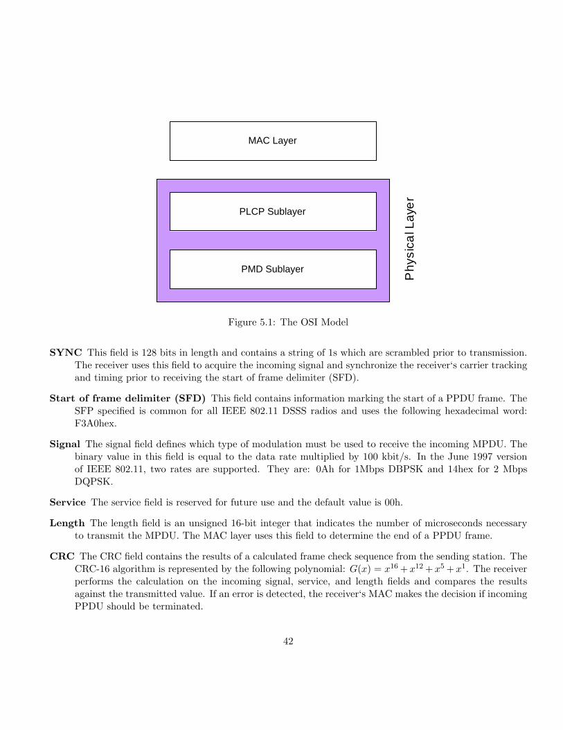
MAC Layer
PLCP Sublayer
PMD Sublayer
P h
y s i c
a l L
a y e
r
Figure 5.1: The OSI Model
SYNC This field is 128 bits in length and contains a string of 1s which are scrambled prior to transmission.The receiver uses this field to acquire the incoming signal and synchronize the receiver‘s carrier trackingand timing prior to receiving the start of frame delimiter (SFD).
Start of frame delimiter (SFD) This field contains information marking the start of a PPDU frame. TheSFP specified is common for all IEEE 802.11 DSSS radios and uses the following hexadecimal word:F3A0hex.
Signal The signal field defines which type of modulation must be used to receive the incoming MPDU. Thebinary value in this field is equal to the data rate multiplied by 100 kbit/s. In the June 1997 versionof IEEE 802.11, two rates are supported. They are: 0Ah for 1Mbps DBPSK and 14hex for 2 MbpsDQPSK.
Service The service field is reserved for future use and the default value is 00h.
Length The length field is an unsigned 16-bit integer that indicates the number of microseconds necessaryto transmit the MPDU. The MAC layer uses this field to determine the end of a PPDU frame.
CRC The CRC field contains the results of a calculated frame check sequence from the sending station. TheCRC-16 algorithm is represented by the following polynomial: G(x) = x16 +x12 +x5 +x1. The receiverperforms the calculation on the incoming signal, service, and length fields and compares the resultsagainst the transmitted value. If an error is detected, the receiver‘s MAC makes the decision if incomingPPDU should be terminated.
42
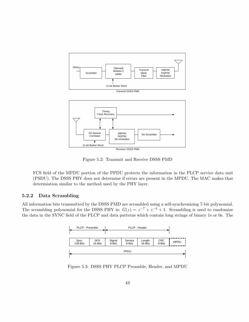
Scrambler
(Spread) Modulo-2
Adder
Transmit Mask Filter
DBPSK DQPSK
Modulator
PPDU
11-bit Barker Word
Transmit DSSS PMD
De-Spread Correlator
DBPSK DQPSK
De-modulator
Timing Clock Recovery
De-Scrambler
11-bit Barker Word
Receiver DSSS PMD
Figure 5.2: Transmit and Receive DSSS PMD
FCS field of the MPDU portion of the PPDU protects the information in the PLCP service data unit(PSDU). The DSSS PHY does not determine if errors are present in the MPDU. The MAC makes thatdetermiation similar to the method used by the PHY layer.
5.2.2 Data Scrambling
All information bits transmitted by the DSSS PMD are scrambled using a self-synchronizing 7-bit polynomial.The scrambling polynomial for the DSSS PHY is: G(z) = z−7 + z−4 + 1. Scrambling is used to randomizethe data in the SYNC field of the PLCP and data patterns which contain long strings of binary 1s or 0s. The
Sync 128-Bits
SFD 16-Bits
Signal 8-Bits
Service 8-Bits
Length 16-Bits
CRC 8-Bits
MPDU
PLCP - Preamble PLCP - Header
PPDU
Figure 5.3: DSSS PHY PLCP Preamble, Header, and MPDU
43
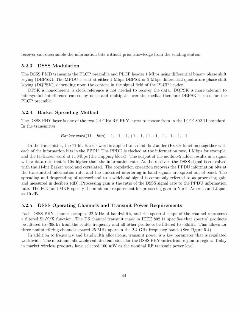
receiver can descramble the information bits without prior knowledge from the sending station.
5.2.3 DSSS Modulation
The DSSS PMD transmits the PLCP preamble and PLCP header 1 Mbps using differential binary phase shiftkeying (DBPSK). The MPDU is sent at either 1 Mbps DBPSK or 2 Mbps differential quadrature phase shiftkeying (DQPSK), depending upon the content in the signal field of the PLCP header.
DPSK is noncoherent; a clock reference is not needed to recover the data. DQPSK is more tolerant tointersymbol interference caused by noise and multipath over the media; therefore DBPSK is used for thePLCP preamble.
5.2.4 Barker Spreading Method
The DSSS PHY layer is one of the two 2.4 GHz RF PHY layers to choose from in the IEEE 802.11 standard.In the transmitter
Barker word(11− bits) + 1,−1, +1, +1,−1,+1, +1, +1,−1,−1,−1
In the transmitter, the 11-bit Barker word is applied to a modulo-2 adder (Ex-Or function) together witheach of the information bits in the PPDU. The PPDU is clocked at the information rate, 1 Mbps for example,and the 11-Barker word at 11 Mbps (the chipping block). The output of the modulo-2 adder results in a signalwith a data rate that is 10x higher than the information rate. At the receiver, the DSSS signal is convolvedwith the 11-bit Barker word and correlated. The correlation operation recovers the PPDU information bits atthe transmitted information rate, and the undesired interfering in-band signals are spread out-of-band. Thespreading and despreading of narrowband to a wideband signal is commonly referred to as processing gainand measured in decibels (dB). Processing gain is the ratio of the DSSS signal rate to the PPDU informationrate. The FCC and MKK specify the minimum requirement for processing gain in North America and Japanas 10 dB.
5.2.5 DSSS Operating Channels and Transmit Power Requirements
Each DSSS PHY channel occupies 22 MHz of bandwidth, and the spectral shape of the channel representsa filtered SinX/X function. The DS channel transmit mask in IEEE 802.11 specifies that spectral productsbe filtered to -30dBr from the center frequency and all other products be filtered to -50dBr. This allows forthree noninterfering channels spaced 25 MHz apart in the 2.4 GHz frequency band. (See Figure 5.4)
In addition to frequency and bandwidth allocations, transmit power is a key parameter that is regulatedworldwide. The maximum allowable radiated emissions for the DSSS PHY varies from region to region. Todayin market wireless products have selected 100 mW as the nominal RF transmit power level.
44
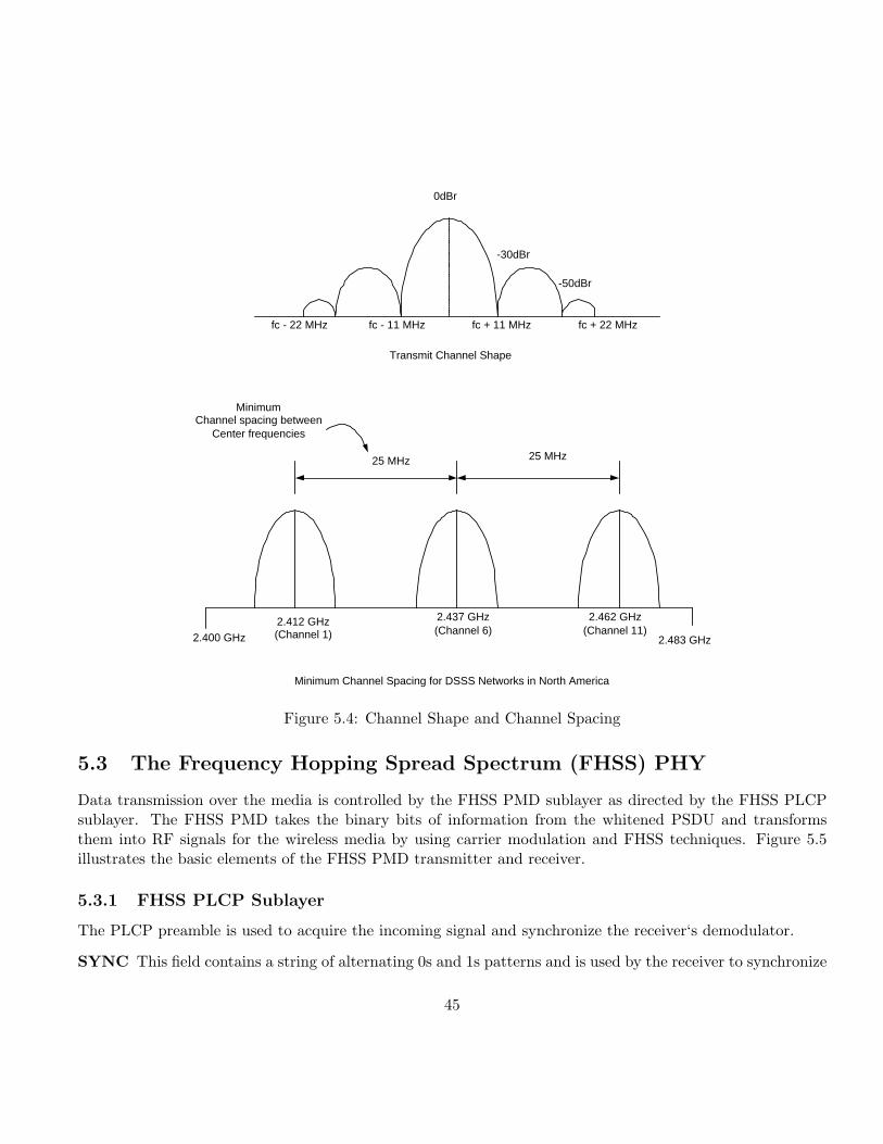
0dBr
-30dBr
-50dBr
fc - 11 MHz fc + 11 MHz fc + 22 MHz fc - 22 MHz
Transmit Channel Shape
25 MHz 25 MHz
Minimum Channel spacing between
Center frequencies
2.400 GHz
2.412 GHz (Channel 1)
2.437 GHz (Channel 6)
2.462 GHz (Channel 11)
2.483 GHz
Minimum Channel Spacing for DSSS Networks in North America
Figure 5.4: Channel Shape and Channel Spacing
5.3 The Frequency Hopping Spread Spectrum (FHSS) PHY
Data transmission over the media is controlled by the FHSS PMD sublayer as directed by the FHSS PLCPsublayer. The FHSS PMD takes the binary bits of information from the whitened PSDU and transformsthem into RF signals for the wireless media by using carrier modulation and FHSS techniques. Figure 5.5illustrates the basic elements of the FHSS PMD transmitter and receiver.
5.3.1 FHSS PLCP Sublayer
The PLCP preamble is used to acquire the incoming signal and synchronize the receiver‘s demodulator.
SYNC This field contains a string of alternating 0s and 1s patterns and is used by the receiver to synchronize
45
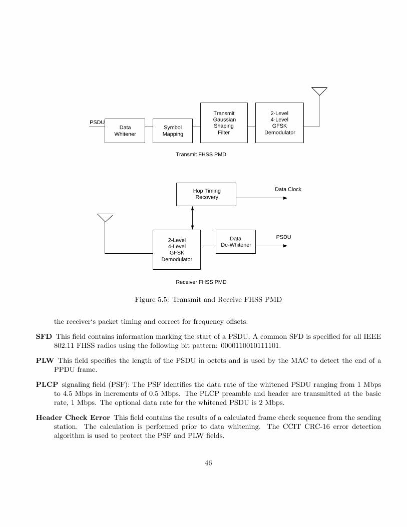
Data Whitener
Symbol Mapping
Transmit Gaussian Shaping
Filter
Hop Timing Recovery
Data De-Whitener
2-Level 4-Level GFSK
Demodulator
2-Level 4-Level GFSK
Demodulator
PSDU
Data Clock
PSDU
Transmit FHSS PMD
Receiver FHSS PMD
Figure 5.5: Transmit and Receive FHSS PMD
the receiver‘s packet timing and correct for frequency offsets.
SFD This field contains information marking the start of a PSDU. A common SFD is specified for all IEEE802.11 FHSS radios using the following bit pattern: 0000110010111101.
PLW This field specifies the length of the PSDU in octets and is used by the MAC to detect the end of aPPDU frame.
PLCP signaling field (PSF): The PSF identifies the data rate of the whitened PSDU ranging from 1 Mbpsto 4.5 Mbps in increments of 0.5 Mbps. The PLCP preamble and header are transmitted at the basicrate, 1 Mbps. The optional data rate for the whitened PSDU is 2 Mbps.
Header Check Error This field contains the results of a calculated frame check sequence from the sendingstation. The calculation is performed prior to data whitening. The CCIT CRC-16 error detectionalgorithm is used to protect the PSF and PLW fields.
46
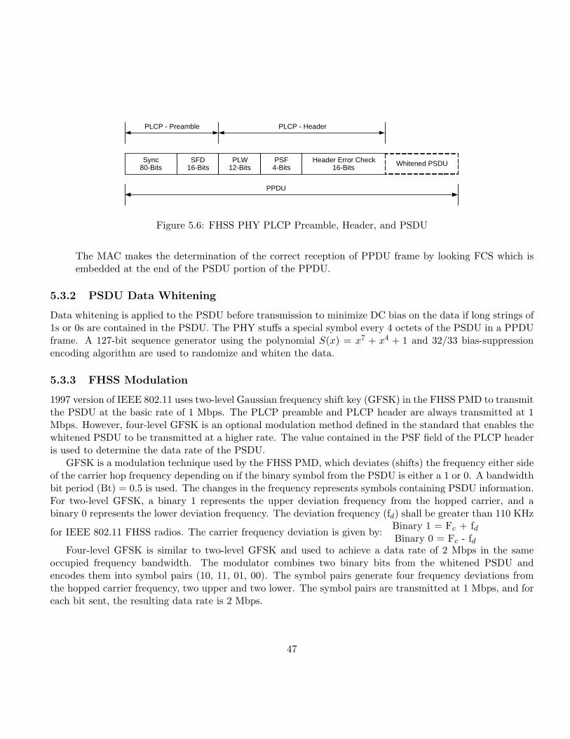
Sync 80-Bits
SFD 16-Bits
PLW 12-Bits
PSF 4-Bits
Header Error Check 16-Bits
Whitened PSDU
PLCP - Preamble PLCP - Header
PPDU
Figure 5.6: FHSS PHY PLCP Preamble, Header, and PSDU
The MAC makes the determination of the correct reception of PPDU frame by looking FCS which isembedded at the end of the PSDU portion of the PPDU.
5.3.2 PSDU Data Whitening
Data whitening is applied to the PSDU before transmission to minimize DC bias on the data if long strings of1s or 0s are contained in the PSDU. The PHY stuffs a special symbol every 4 octets of the PSDU in a PPDUframe. A 127-bit sequence generator using the polynomial S(x) = x7 + x4 + 1 and 32/33 bias-suppressionencoding algorithm are used to randomize and whiten the data.
5.3.3 FHSS Modulation
1997 version of IEEE 802.11 uses two-level Gaussian frequency shift key (GFSK) in the FHSS PMD to transmitthe PSDU at the basic rate of 1 Mbps. The PLCP preamble and PLCP header are always transmitted at 1Mbps. However, four-level GFSK is an optional modulation method defined in the standard that enables thewhitened PSDU to be transmitted at a higher rate. The value contained in the PSF field of the PLCP headeris used to determine the data rate of the PSDU.
GFSK is a modulation technique used by the FHSS PMD, which deviates (shifts) the frequency either sideof the carrier hop frequency depending on if the binary symbol from the PSDU is either a 1 or 0. A bandwidthbit period (Bt) = 0.5 is used. The changes in the frequency represents symbols containing PSDU information.For two-level GFSK, a binary 1 represents the upper deviation frequency from the hopped carrier, and abinary 0 represents the lower deviation frequency. The deviation frequency (fd) shall be greater than 110 KHz
for IEEE 802.11 FHSS radios. The carrier frequency deviation is given by:Binary 1 = Fc + fdBinary 0 = Fc - fd
Four-level GFSK is similar to two-level GFSK and used to achieve a data rate of 2 Mbps in the sameoccupied frequency bandwidth. The modulator combines two binary bits from the whitened PSDU andencodes them into symbol pairs (10, 11, 01, 00). The symbol pairs generate four frequency deviations fromthe hopped carrier frequency, two upper and two lower. The symbol pairs are transmitted at 1 Mbps, and foreach bit sent, the resulting data rate is 2 Mbps.
47
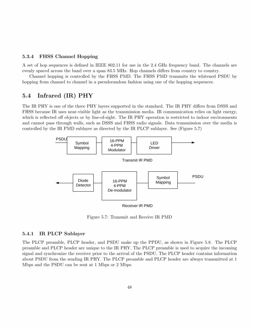
5.3.4 FHSS Channel Hopping
A set of hop sequences is defined in IEEE 802.11 for use in the 2.4 GHz frequency band. The channels areevenly spaced across the band over a span 83.5 MHz. Hop channels differs from country to country.
Channel hopping is controlled by the FHSS PMD. The FHSS PMD transmits the whitened PSDU byhopping from channel to channel in a pseudorandom fashion using one of the hopping sequences.
5.4 Infrared (IR) PHY
The IR PHY is one of the three PHY layers supported in the standard. The IR PHY differs from DSSS andFHSS because IR uses near-visible light as the transmission media. IR communication relies on light energy,which is reflected off objects or by line-of-sight. The IR PHY operation is restricted to indoor environmentsand cannot pass through walls, such as DSSS and FHSS radio signals. Data transmission over the media iscontrolled by the IR PMD sublayer as directed by the IR PLCP sublayer. See (Figure 5.7)
Symbol Mapping
16-PPM 4-PPM
Modulator
LED Driver
Diode Detector
Symbol Mapping 16-PPM
4-PPM De-modulator
PSDU
PSDU
Transmit IR PMD
Receiver IR PMD
Figure 5.7: Transmit and Receive IR PMD
5.4.1 IR PLCP Sublayer
The PLCP preamble, PLCP header, and PSDU make up the PPDU, as shown in Figure 5.8. The PLCPpreamble and PLCP header are unique to the IR PHY. The PLCP preamble is used to acquire the incomingsignal and synchronize the receiver prior to the arrival of the PSDU. The PLCP header contains informationabout PSDU from the sending IR PHY. The PLCP preamble and PLCP header are always transmitted at 1Mbps and the PSDU can be sent at 1 Mbps or 2 Mbps.
48
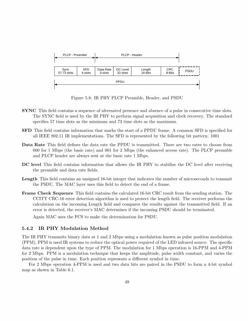
Sync 57-73 slots
SFD 4-slots
Data Rate 3-slots
DC Level 32-slots
Length 16-Bits
PSDU
PLCP - Preamble PLCP - Header
PPDU
CRC 8-Bits
Figure 5.8: IR PHY PLCP Preamble, Header, and PSDU
SYNC This field contains a sequence of alternated presence and absence of a pulse in consecutive time slots.The SYNC field is used by the IR PHY to perform signal acquisition and clock recovery. The standardspecifies 57 time slots as the minimum and 73 time slots as the maximum.
SFD This field contains information that marks the start of a PPDU frame. A common SFD is specified forall IEEE 802.11 IR implementations. The SFD is represented by the following bit pattern: 1001
Data Rate This field defines the data rate the PPDU is transmitted. There are two rates to choose from000 for 1 Mbps (the basic rate) and 001 for 2 Mbps (the enhanced access rate). The PLCP preambleand PLCP header are always sent at the basic rate 1 Mbps.
DC level This field contains information that allows the IR PHY to stabilize the DC level after receivingthe preamble and data rate fields.
Length This field contains an unsigned 16-bit integer that indicates the number of microseconds to transmitthe PSDU. The MAC layer uses this field to detect the end of a frame.
Frame Check Sequence This field contains the calculated 16-bit CRC result from the sending station. TheCCITT CRC-16 error detection algorithm is used to protect the length field. The receiver performs thecalculation on the incoming Length field and compares the results against the transmitted field. If anerror is detected, the receiver‘s MAC determines if the incoming PSDU should be terminated.
Again MAC uses the FCS to make the determination for PSDU.
5.4.2 IR PHY Modulation Method
The IR PHY transmits binary data at 1 and 2 Mbps using a modulation known as pulse position modulation(PPM). PPM is used IR systems to reduce the optical power required of the LED infrared source. The specificdata rate is dependent upon the type of PPM. The modulation for 1 Mbps operation is 16-PPM and 4-PPMfor 2 Mbps. PPM is a modulation technique that keeps the amplitude, pulse width constant, and varies theposition of the pulse in time. Each position represents a different symbol in time.
For 2 Mbps operation 4-PPM is used and two data bits are paired in the PSDU to form a 4-bit symbolmap as shown in Table 6.1.
49
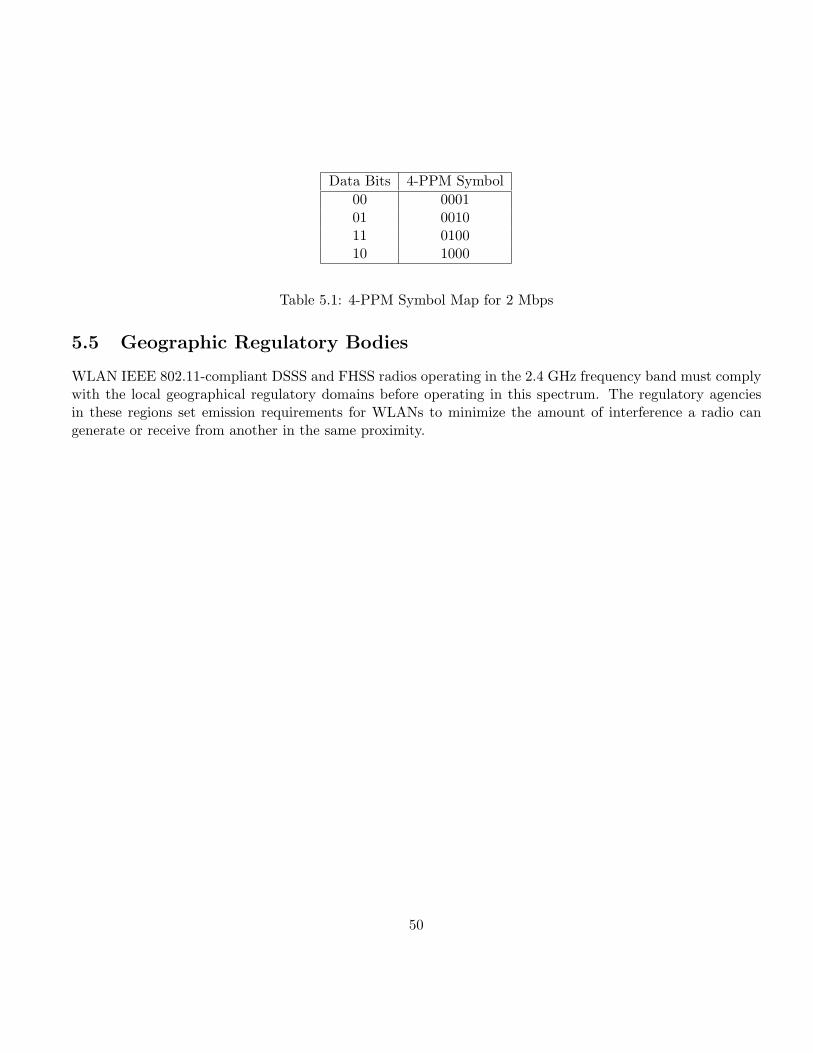
Data Bits 4-PPM Symbol00 000101 001011 010010 1000
Table 5.1: 4-PPM Symbol Map for 2 Mbps
5.5 Geographic Regulatory Bodies
WLAN IEEE 802.11-compliant DSSS and FHSS radios operating in the 2.4 GHz frequency band must complywith the local geographical regulatory domains before operating in this spectrum. The regulatory agenciesin these regions set emission requirements for WLANs to minimize the amount of interference a radio cangenerate or receive from another in the same proximity.
50
Chapter 6
Physical Layer Extensions to IEEE 802.11
In October 1997 the IEEE 802 Executive Committee approved two projects to for higher rate physical layer(PHY) extensions to IEEE 802.11. The first extension, IEEE 802.11a, defines requirements for a PHYoperating in the 5.0 GHz U-NII frequency and data rates ranging from 6 Mbps to 54 Mbps.
The second extension, IEEE 802.11b, defines a set of PHY specifications operating in the 2.4 GHz ISMfrequency band up to 11 Mbps. Both PHY are defined to operate with the existing MAC.
6.1 IEEE 802.11a - The OFDM Physical Layer
The IEEE 802.11a PHY i adopts orthogonal frequency division multiplexing (OFDM) PHY. The OFDM PHYprovides the capability to transmit PSDU frames at multiple data rates up to 54 Mbps for WLAN networkswhere transmission of multimedia content is a consideration.
6.1.1 OFDM PLCP Sublayer
The PPDU is unique to the OFDM PHY. The PPDU frame consists of a PLCP preamble and signal and datafields as shown in Figure 6.1.
The receiver uses the PLCP preamble to acquire the incoming OFDM signal and synchronize the demod-ulator. The PLCP header contains information about the PSDU from the sending OFDM PHY. The PLCPpreamble and the signal field are always transmitted at 6 Mbps, binary phase shift keying (BPSK) - OFDMmodulated using convolutional encoding rate R=1/2.
PLCP preamble This field is used to acquire the incoming signal and train and synchronize the receiver.The PLCP preamble consists of 12 symbols, ten of which are short symbols, and two long symbols.The short symbols are used to train the receiver‘s AGC and obtain a coarse estimate of the carrierfrequency and the channel. The long symbols are used to fine-tune the frequency and channel estimates.Twelve sub-carriers are used for the short symbols and 53 for the long. The training of an OFDM isaccomplished in 16 µs. PLCP preamble is BPSK-OFDM modulated at 6 Mbps.
51
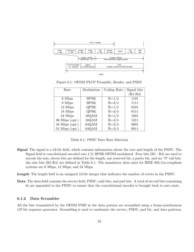
Rate 4 - Bits
Reserved 1 - Bits
Length 12 - Bits
Parity 1 - Bits
Tail 6 - Bits
PSDU
Coded - OFDM BPSK Rate = 1/2
PLCP - Header
PPDU
Service 16 - Bits
Tail 6 - Bits
Pad Bits
PLCP Preamble 12 - Symbols
Signal (1) OFDM Symbol
Data Variable number of OFDM Symbols
Coded - OFDM Rate indicated by Signal Symbol
Figure 6.1: OFDM PLCP Preamble, Header, and PSDU
Rate Modulation Coding Rate Signal bits(R1-R4)
6 Mbps BPSK R=1/2 11019 Mbps BPSK R=3/4 111112 Mbps QPSK R=1/2 010118 Mbps QPSK R=3/4 011124 Mbps 16QAM R=1/2 1001
36 Mbps (opt.) 16QAM R=3/4 101148 Mbps (opt.) 64QAM R=2/3 000154 Mbps (opt.) 64QAM R=3/4 0011
Table 6.1: PSDU Date Rate Selection
Signal The signal is a 24-bit field, which contains information about the rate and length of the PSDU. TheSignal field is convolutional encoded rate 1/2, BPSK-OFDM modulated. Four bits (R1 - R4) are used toencode the rate, eleven bits are defined for the length, one reserved bit, a parity bit, and six “0” tail bits.the rate bits (R1-R4) are defined in Table 6.1. The mandatory data rates for IEEE 802.11a-compliantsystems are 6 Mbps, 12 Mbps, and 24 Mbps.
Length The length field is an unsigned 12-bit integer that indicates the number of octets in the PSDU.
Data The data field contains the service field, PSDU, tails bits, and pad bits. A total of six tail bits containing0s are appended to the PPDU to ensure that the convolutional encoder is brought back to zero state.
6.1.2 Data Scrambler
All the bits transmitted by the OFDM PMD in the data portion are scrambled using a frame-synchronous127-bit sequence generator. Scrambling is used to randomize the service, PSDU, pad bit, and data patterns,
52
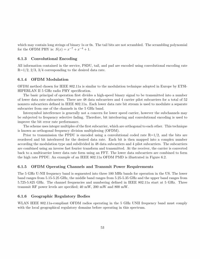
which may contain long strings of binary 1s or 0s. The tail bits are not scrambled. The scrambling polynomialfor the OFDM PHY is: S(x) = x−7 + x−4 + 1.
6.1.3 Convolutional Encoding
All information contained in the service, PSDU, tail, and pad are encoded using convolutional encoding rateR=1/2, 2/3, 3/4 corresponding to the desired data rate.
6.1.4 OFDM Modulation
OFDM method chosen for IEEE 802.11a is similar to the modulation technique adopted in Europe by ETSI-HIPERLAN II 5 GHz radio PHY specification.
The basic principal of operation first divides a high-speed binary signal to be transmitted into a numberof lower data rate subcarriers. There are 48 data subcarriers and 4 carrier pilot subcarriers for a total of 52nonzero subcarriers defined in IEEE 802.11a. Each lower data rate bit stream is used to modulate a separatesubcarrier from one of the channels in the 5 GHz band.
Intersymbol interference is generally not a concern for lower speed carrier, however the subchannels maybe subjected to frequency selective fading. Therefore, bit interleaving and convolutional encoding is used toimprove the bit error rate performance.
The scheme uses integer multiples of the first subcarrier, which are orthogonal to each other. This techniqueis known as orthogonal frequency division multiplexing (OFDM).
Prior to transmission the PPDU is encoded using a convolutional coded rate R=1/2, and the bits arereordered and bit interleaved for the desired data rate. Each bit is then mapped into a complex numberaccording the modulation type and subdivided in 48 data subcarriers and 4 pilot subcarriers. The subcarriersare combined using an inverse fast fourier transform and transmitted. At the receiver, the carrier is convertedback to a multicarrier lower data rate form using an FFT. The lower data subcarriers are combined to formthe high rate PPDU. An example of an IEEE 802.11a OFDM PMD is illustrated in Figure 6.2.
6.1.5 OFDM Operating Channels and Transmit Power Requirements
The 5 GHz U-NII frequency band is segmented into three 100 MHz bands for operation in the US. The lowerband ranges from 5.15-5.25 GHz, the middle band ranges from 5.25-5.35 GHz and the upper band ranges from5.725-5.825 GHz. The channel frequencies and numbering defined in IEEE 802.11a start at 5 GHz. Threetransmit RF power levels are specified; 40 mW, 200 mW and 800 mW.
6.1.6 Geographic Regulatory Bodies
WLAN IEEE 802.11a-compliant OFDM radios operating in the 5 GHz UNII frequency band must complywith the local geographical regulatory domains before operating in this spectrum.
53
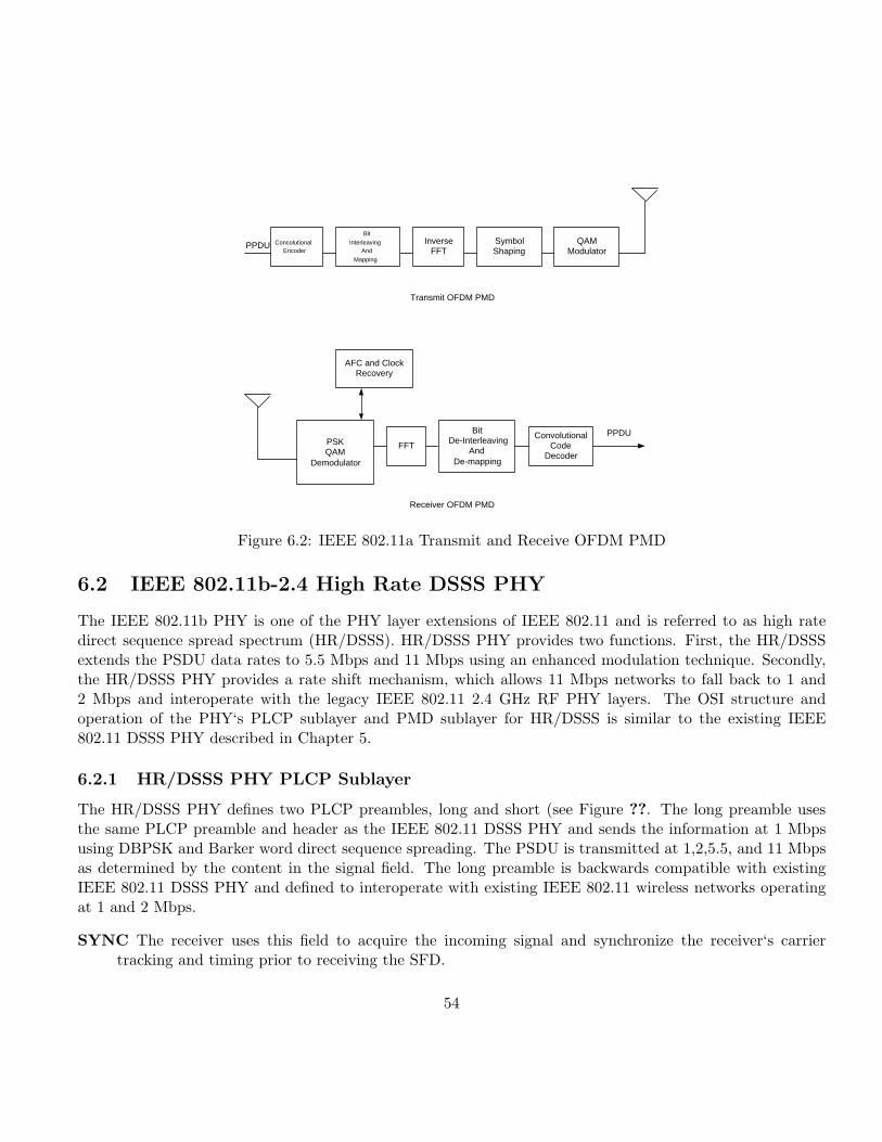
Concolutional Encoder
Inverse FFT
Symbol Shaping
AFC and Clock Recovery
Bit De-Interleaving
And De-mapping
QAM Modulator
PSK QAM
Demodulator
PPDU
PPDU
Transmit OFDM PMD
Receiver OFDM PMD
Bit
Interleaving And
Mapping
FFT Convolutional
Code Decoder
Figure 6.2: IEEE 802.11a Transmit and Receive OFDM PMD
6.2 IEEE 802.11b-2.4 High Rate DSSS PHY
The IEEE 802.11b PHY is one of the PHY layer extensions of IEEE 802.11 and is referred to as high ratedirect sequence spread spectrum (HR/DSSS). HR/DSSS PHY provides two functions. First, the HR/DSSSextends the PSDU data rates to 5.5 Mbps and 11 Mbps using an enhanced modulation technique. Secondly,the HR/DSSS PHY provides a rate shift mechanism, which allows 11 Mbps networks to fall back to 1 and2 Mbps and interoperate with the legacy IEEE 802.11 2.4 GHz RF PHY layers. The OSI structure andoperation of the PHY‘s PLCP sublayer and PMD sublayer for HR/DSSS is similar to the existing IEEE802.11 DSSS PHY described in Chapter 5.
6.2.1 HR/DSSS PHY PLCP Sublayer
The HR/DSSS PHY defines two PLCP preambles, long and short (see Figure ??. The long preamble usesthe same PLCP preamble and header as the IEEE 802.11 DSSS PHY and sends the information at 1 Mbpsusing DBPSK and Barker word direct sequence spreading. The PSDU is transmitted at 1,2,5.5, and 11 Mbpsas determined by the content in the signal field. The long preamble is backwards compatible with existingIEEE 802.11 DSSS PHY and defined to interoperate with existing IEEE 802.11 wireless networks operatingat 1 and 2 Mbps.
SYNC The receiver uses this field to acquire the incoming signal and synchronize the receiver‘s carriertracking and timing prior to receiving the SFD.
54
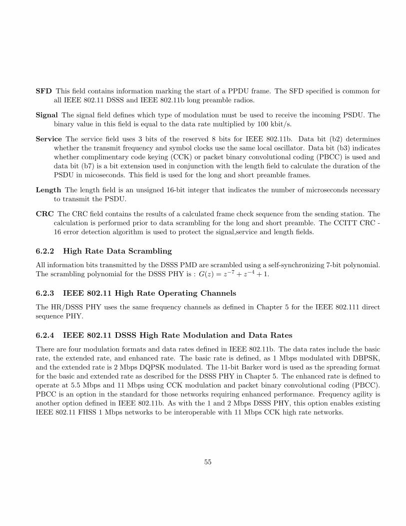
SFD This field contains information marking the start of a PPDU frame. The SFD specified is common forall IEEE 802.11 DSSS and IEEE 802.11b long preamble radios.
Signal The signal field defines which type of modulation must be used to receive the incoming PSDU. Thebinary value in this field is equal to the data rate multiplied by 100 kbit/s.
Service The service field uses 3 bits of the reserved 8 bits for IEEE 802.11b. Data bit (b2) determineswhether the transmit frequency and symbol clocks use the same local oscillator. Data bit (b3) indicateswhether complimentary code keying (CCK) or packet binary convolutional coding (PBCC) is used anddata bit (b7) is a bit extension used in conjunction with the length field to calculate the duration of thePSDU in micoseconds. This field is used for the long and short preamble frames.
Length The length field is an unsigned 16-bit integer that indicates the number of microseconds necessaryto transmit the PSDU.
CRC The CRC field contains the results of a calculated frame check sequence from the sending station. Thecalculation is performed prior to data scrambling for the long and short preamble. The CCITT CRC -16 error detection algorithm is used to protect the signal,service and length fields.
6.2.2 High Rate Data Scrambling
All information bits transmitted by the DSSS PMD are scrambled using a self-synchronizing 7-bit polynomial.The scrambling polynomial for the DSSS PHY is : G(z) = z−7 + z−4 + 1.
6.2.3 IEEE 802.11 High Rate Operating Channels
The HR/DSSS PHY uses the same frequency channels as defined in Chapter 5 for the IEEE 802.111 directsequence PHY.
6.2.4 IEEE 802.11 DSSS High Rate Modulation and Data Rates
There are four modulation formats and data rates defined in IEEE 802.11b. The data rates include the basicrate, the extended rate, and enhanced rate. The basic rate is defined, as 1 Mbps modulated with DBPSK,and the extended rate is 2 Mbps DQPSK modulated. The 11-bit Barker word is used as the spreading formatfor the basic and extended rate as described for the DSSS PHY in Chapter 5. The enhanced rate is defined tooperate at 5.5 Mbps and 11 Mbps using CCK modulation and packet binary convolutional coding (PBCC).PBCC is an option in the standard for those networks requiring enhanced performance. Frequency agility isanother option defined in IEEE 802.11b. As with the 1 and 2 Mbps DSSS PHY, this option enables existingIEEE 802.11 FHSS 1 Mbps networks to be interoperable with 11 Mbps CCK high rate networks.
55
6.2.5 Complementary Code Keying (CCK) Modulation
CCK for the high rate extension to deliver PSDU frames at speeds of 5.5 Mbps and 11 Mbps was adoptedbecause it easily provides a path for interoperability with existing IEEE 802.11 1 and 2 Mbps systems bymaintaining the same bandwidth and incorporating the existing DSSS PHY PLCP preamble and header.
6.2.6 DSSS Packet Binary Convolutional Coding
Packet binary convolutional coding (PBCC) is an optional coding scheme defined in IEEE 802.11b. Thecoding option uses a 64-state binary convolutional code (BCC), rate R=1/2 code, and a cover sequence. TheHR/DSSS PMD uses PBCC to transmit the PPDU. To ensure that the PPDU frame is properly decoded atthe receiver, the BCC encoder‘s memory is cleared at the end of a frame.
6.2.7 Frequency Hopped Spread Spectrum (FHSS)Inter operability
A channel agility option is defined in IEEE 802.11b which allows IEEE 802.11 FHSS 1 and 2 Mbps networks tointeroperate with HR/DSSS 11 Mbps WLANs. Both nonoverlapping and overlapping high rate channels aresupported. The nonoverlapping allows WLAN systems to operate simultaneously in the same area withoutinterfering with each other. Two sets of hopping sequence are defined for worldwide operation. For moredetails on the hop patterns refer to IEEE 802.11b.
56
Chapter 7
System Design Considerations for IEEE802.11 WLANs
The IEEE 802.11 WLAN standard provides a number of physical layer options in terms of data rates, mod-ulation types, and spreading spectrum techniques. Selecting the right physical layer and MAC technologiesrequires careful planning and detailed systems analysis for developing the optimal WLAN implementation.
7.1 The Medium
The difference between ”wired” and RF WLANs is the radio communications link. While the radio commu-nications link provides the freedom to move without constraints of wires, the wired media has the luxury of acontrolled propagation media. Wireless RF medias are very difficult to control because the dynamics of thepropagated signals over the media are constantly changing. RF medium is understood to properly design 2.4GHz and 5 GHz IEEE 802.11 WLAN systems, especially for networks operating at data rates greater than 2Mbps since these bands are shared with unlicenced users.
7.2 Multipath
Multipath is one of the performance concerns for indoor IEEE 802.11 WLAN systems. Multipath occurswhen the direct path of the transmitted signal is combined with paths of the reflected signal paths, resultingin a corrupted signal at the receiver. The delay of the reflected signals known as delay spread is measured innanoseconds. Delay spread is the parameter used to signify multipath. The amount of delay spread varies forenvironments see Table ??.
RAKE processing and equalization are two methods used to process and resolve delay spread. A RAKEreceiver is well-known architecture used to remove delay spreads on the order of 100nsec. The RAKE isstructured as a bank of correlators (fingers) with weighed delays and a combiner. Equalization is an alternative
57
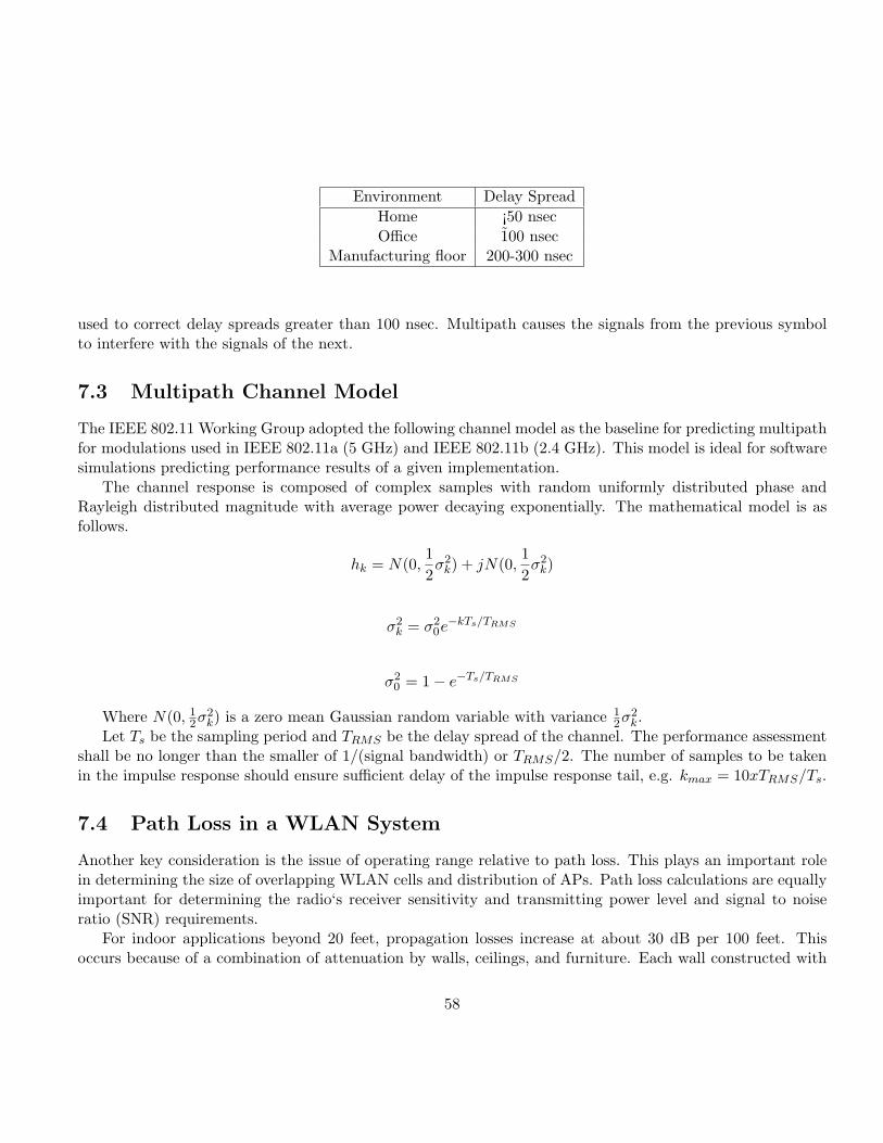
Environment Delay SpreadHome ¡50 nsecOffice 1̃00 nsec
Manufacturing floor 200-300 nsec
used to correct delay spreads greater than 100 nsec. Multipath causes the signals from the previous symbolto interfere with the signals of the next.
7.3 Multipath Channel Model
The IEEE 802.11 Working Group adopted the following channel model as the baseline for predicting multipathfor modulations used in IEEE 802.11a (5 GHz) and IEEE 802.11b (2.4 GHz). This model is ideal for softwaresimulations predicting performance results of a given implementation.
The channel response is composed of complex samples with random uniformly distributed phase andRayleigh distributed magnitude with average power decaying exponentially. The mathematical model is asfollows.
hk = N(0,12σ2
k) + jN(0,12σ2
k)
σ2k = σ2
0e−kTs/TRMS
σ20 = 1− e−Ts/TRMS
Where N(0, 12σ2
k) is a zero mean Gaussian random variable with variance 12σ2
k.Let Ts be the sampling period and TRMS be the delay spread of the channel. The performance assessment
shall be no longer than the smaller of 1/(signal bandwidth) or TRMS/2. The number of samples to be takenin the impulse response should ensure sufficient delay of the impulse response tail, e.g. kmax = 10xTRMS/Ts.
7.4 Path Loss in a WLAN System
Another key consideration is the issue of operating range relative to path loss. This plays an important rolein determining the size of overlapping WLAN cells and distribution of APs. Path loss calculations are equallyimportant for determining the radio‘s receiver sensitivity and transmitting power level and signal to noiseratio (SNR) requirements.
For indoor applications beyond 20 feet, propagation losses increase at about 30 dB per 100 feet. Thisoccurs because of a combination of attenuation by walls, ceilings, and furniture. Each wall constructed with
58
sheet rock and wood typically attenuates the signal by 6 dB and walls constructed with cement block wallsattenuate the signal by 4 dB. However, additional losses may occur depending on the fading characteristics ofthe operating environment. The sam path principles apply for all frequency bands. However, as the operatingfrequency increases from 2.4 GHz to 5 GHz, for example, and additional path loss of 5-10 dB occurs. Thisresults in a smaller cell radius and may require additional overlapping cells and APs to guarantee the samearea as a system operating at 2.4 GHz.
7.5 Multipath Fading
Another key consideration is the path loss due to multipath fading. Multipath fading occurs when the reflectedsignal paths refract off people, furniture, windows, and scatter the transmitted signal. For example, movingthe receiver from the transmitter a small distance even only a few inches, can produce an additional loss ofsignal power on the order of 20 dB or more. Multipath fading is viewed as two separate factors and describedas probability distribution functions. The first factor is a characteristic known as log normal fading. Theseare coefficient products which result as the signal reflects off surfaces and propagates to the receiver. As thesignal coefficients product propagate to the receiver, they are summed together with the direct path wherethey cancel each other, causing significant attention of the transmitted singal. This is the second factor, knownas Rayleigh fading. RAKE architectures and equalization are techniques used to correct for these effects.
7.6 Es/No vs BER Performance
System performance tradeoffs are often made in the decision process when selecting a modulation type anddata rate. System tradeoffs in terms of receiver sensitivity, range, and transmit power become very importantfor developing low cost implementations, especially for higher rate 2.4 GHz IEEE 802.11b systems.
7.7 Data Rage vs Aggregate Throughput
The IEEE 802.11 standard defines data rate in terms of symbol rate, or available bit rate. The PPDU datais modulated and transmitted over the RF or IR medium at this rate. This rate is often confused with theaggregate data throughput. The aggregate data rate, takes into account the overhead associated with protocolframe structure, collisions, and implementation processing delays associated with frames processed by mobilestations and APs. A good rule of thumb for estimating the average aggregate throughput of an IEEE 802.11wireless network is 75% of the data rate for DCF operation, and 85% of the data rate for PCF.
7.8 WLAN Installation and Site Survey
A site survey is used to determine the maximum operating range between and AP (fixed location) and mobilestations for a specified transmit RF power level. Second, the survey helps identify holes of coverage due
59
to multipath, interference sources, and neighboring existing WLAN installations. Lastly, it is used in cellplanning of overlapping BSAs and for layout of APs giving them hardwired access to existing wired EthernetLAN infrastructures.
7.9 Interference in the 2.4 GHz Frequency Band
The microwave oven used in household and commercial kitchens is the main interference source in the 2.4GHz unlicensed frequency band. The magnetron tubes used in the microwave ovens radiate a continuous-wave-like (CW-like) interference that sweeps over tens of megahertz (MHz) of the 2.4-2.483 GHz band duringthe positive half cycle of ac line voltage. The microwave oven‘s EIRP has a maximum ranging between 16and 33 dBm. The power cycle frequency is 50 Hz 20 msec or 60 Hz 16 msec depending upon the geographicallocation. In North America, the ac line frequency is 60 HZ and the microwave oven‘s magnetron pulses onfor 8msec and off for 8 msec. The maximum packet length defined in the IEEE 802.11 protocol was designedto operate between the 8 msec pulses of the microwave energy.
Other sources of interference include neighboring in-band radios that can be minimized by proper cellplanning of the channel frequency and hopping patterns and careful layout of the APs. The second typeof interference is from other systems such as neighboring DSSS and FHSS WLAN networks. Built into thestandard are three mechanisms used to help minimize the amount of interference. The first is the clearchannel assessment, where the MAC layer protocol provides a method of collision avoidance. The second isprocessing gain, which provides some protection from FHSS radios, whose spectrum appears as narrowbandinterferers. The third are the hop patterns; there is sufficient frequency spacing between pseudorandom hopsto minimize the interference due to neighboring DSSS channels. To some degree, legacy 2.4 GHz IEEE 802.11-compliant FHSS and DSSS systems and IEEE 802.11b high-rate WLAN systems do coexist. However, carefulcell planning will help minimize the amount of interference a system will experience especially at the outerfringe of the cell.
7.10 Antenna Diversity
Historically antenna diversity has been an effective low-cost alternative solution used to combat and mitigatethe effects of multipath and delay spread in WLAN radio receivers. It is relatively easy to implement in themobile stations and APs and does not require the signal processing hardware used in other diversity techniques.The object behind antenna diversity is to space the antennas apart from each other to minimize the effectsof the uncorrelated multipath at the receiver. Spacing the antennas far apart allows the receiver to pick anddemodulate the larger signal of the two signals. For 2.4 GHz IEEE 802.11 implementations, the bit lengthof the preamble sync fields was selected based on these criteria. The antennas are typically spaced anywherefrom 0.25l to several lambdas (wavelengths) apart. The amount of separation depends upon the amount ofdelay-spread tolerance required for the system to operate in a given operating environment. Adding antennadiversity will improve the packet error rate (PER) performance of a wireless link by 2 or 1, as well as improvethe availability of the link. There are a number of 2.4 GHz antennas on the market today with different
60
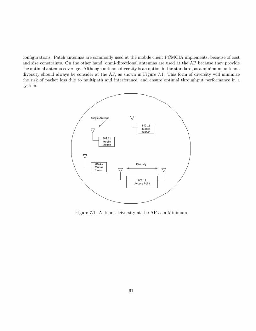
configurations. Patch antennas are commonly used at the mobile client PCMCIA implements, because of costand size constraints. On the other hand, omni-directional antennas are used at the AP because they providethe optimal antenna coverage. Although antenna diversity is an option in the standard, as a minimum, antennadiversity should always be consider at the AP, as shown in Figure 7.1. This form of diversity will minimizethe risk of packet loss due to multipath and interference, and ensure optimal throughput performance in asystem.
802.11 Mobile Station
802.11 Access Point
802.11 Mobile Station
802.11 Mobile Station
Diversity
Single Antenna
Figure 7.1: Antenna Diversity at the AP as a Minimum
61
Chapter 8
IEEE 802.11 PROTOCOLS
8.1 Overview of IEEE 802.11 Standards
In addition to the 802.11a and 802.11b , 802.11 standards are being developed that extend the physical layeroptions, improve security, add quality of service (QoS) features or provide better inter-operability. Ven-dors are likely to offer proprietary implementations of these features before the IEEE finalizes the standards.
IEEE 802.11a A physical layer standard for WLANs in the 5GHz radio band. It specifies eight availableradio channels. Maximum link rate of 54-Mbps per channel. Comments: Higher data throughput andgreater number of channels give better protection against possible interference from neighboring accesspoints. When: Standard completed in 1999. Products are available now.
IEEE 802.11b A physical layer standard for WLANs in the 2.4 GHz radio band. It specifies three availableradio channels. Maximum link rate of 11-Mbps per channel. Comments: Installations may suffer fromspeed restrictions in the future as the number of active users increase, and the limit of three radiochannels may cause interference from neighboring access points. When: Standard completed in 1999.Products have been available since 2001.
IEEE 802.11d 802.11d is supplementary to the Media Access Control layer in 802.11 to promote worldwideuse of 802.11 WLANs. It will allow access points to communicate information on the permissible radiochannels with acceptable power levels for user devices. The 802.11 standards cannot legally operatein some countries; the purpose of 11d is to add features and restrictions to allow WLANs to operatewithin the rules of these countries. Comments: Equipment manufacturers do not want to produce awide variety of country-specific products and users that travel do not want a bag full of country-specificWLAN PC cards. The outcome will be country-specific firmware solutions. When: Work is ongoing,but see 802.11h for a timeline on 5 GHz WLANs in Europe.
IEEE 802.11e Supplementary to the MAC layer to provide QoS support for LAN applications. It will applyto 802.11 physical standards a,b and g. The purpose is to provide classes of service with managed levels
62
of QoS for data, voice and video applications. Comments: 11e should provide some useful featuresfor differentiating data traffic streams. Many WLAN manufacturers have targeted QoS as a featureto differentiate their products, so there will be plenty of proprietary offerings before 11e is complete.When: The finalized standard is expected in the second half of 2002. Products will be available in thesecond half of 2003.
IEEE 802.11f This is a “recommended practice” document that aims to achieve radio access point inter-operability within a multi-vendor WLAN network. The standard defines the registration of access pointswithin a network and the interchange of information between access points when a user is handed overfrom one access point to another. Comments: 802.11f will reduce vendor lock-in and allow multi-vendorinfrastructures. When: Completed standard expected in the second half of 2002. Products will beavailable in the first half of 2003.
IEEE 802.11g A physical layer standard for WLANs in the 2.4 GHz and 5 GHz radio band. It specifiesthree available radio channels. The maximum link rate is 54-Mbps per channel compared with 11Mbps for 11b. The 802.11g standard uses OFDM modulation but, for backward compatibility with11b, it also supports complementary code keying (CCK) modulation and, as an option for faster linkrates, allows packet binary convolutional coding (PBCC) modulation. Comments: Speeds similar to11a and backward compatibility may appear attractive but there are modulation issues: Conflictinginterests between key vendors have divided support within IEEE task group for the OFDM and PBCCmodulation schemes. The task group compromised by including both types of modulation in the draftstandard. With the addition of support for 11b‘s CCK modulation, the end result is three modulationtypes. This is perhaps too little, too late and too complex compared with 11a. However, there areadvantages for vendors looking to supply dual-mode 2.4 GHz and 5 GHz products, in that using OFDMfor both modes will reduce silicon cost. When: Completed standard expected in the second half of 2002.Products will be available in the first half of 2003.
IEEE 802.11h This standard is supplementary to the MAC layer to comply with European regulations for5 GHz WLANs. European radio regulations for the 5 GHz band require products to have transmissionpower control (TPC) and dynamic frequency selection (DFS). TPC limits the transmitted power tothe minimum needed to reach the furthest user. DFS selects the radio channel at the access pointto minimize interference with other systems, particularly radar. Comments: Completion of 11h willprovide better acceptability within Europe for IEEE compliant 5 GHz WLAN products. When: Thestandard is expected to be finalized by the second half of 2002. Products will be available in the firsthalf of 2003.
IEEE 802.11i Supplementary to the MAC layer to improve security. It will apply to 802.11 physical stan-dards a,b and g. It provides an alternative to WEP with new encryption methods and authenticationprocedures. IEEE 802.1x forms a key part of 802.11i. Comments: Security is a major weakness ofWLANs. Weakness of WEP encryption is damaging the 802.11 standard perception in the market.Vendors have not improved matters by shipping products without setting default security features. In
63
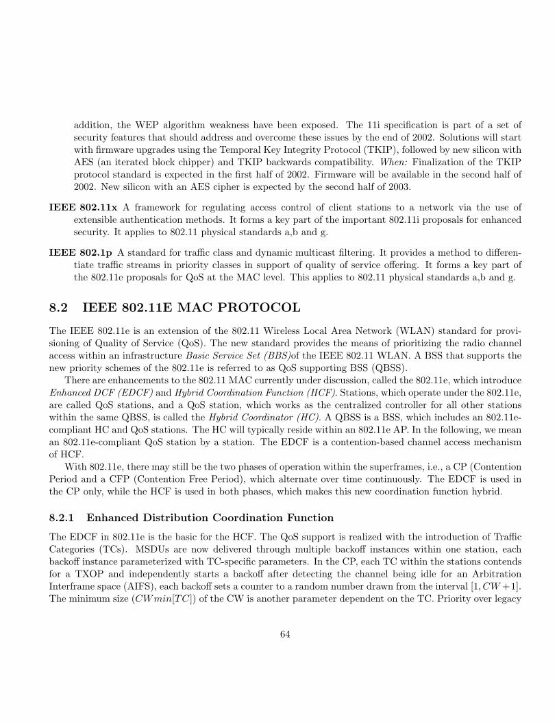
addition, the WEP algorithm weakness have been exposed. The 11i specification is part of a set ofsecurity features that should address and overcome these issues by the end of 2002. Solutions will startwith firmware upgrades using the Temporal Key Integrity Protocol (TKIP), followed by new silicon withAES (an iterated block chipper) and TKIP backwards compatibility. When: Finalization of the TKIPprotocol standard is expected in the first half of 2002. Firmware will be available in the second half of2002. New silicon with an AES cipher is expected by the second half of 2003.
IEEE 802.11x A framework for regulating access control of client stations to a network via the use ofextensible authentication methods. It forms a key part of the important 802.11i proposals for enhancedsecurity. It applies to 802.11 physical standards a,b and g.
IEEE 802.1p A standard for traffic class and dynamic multicast filtering. It provides a method to differen-tiate traffic streams in priority classes in support of quality of service offering. It forms a key part ofthe 802.11e proposals for QoS at the MAC level. This applies to 802.11 physical standards a,b and g.
8.2 IEEE 802.11E MAC PROTOCOL
The IEEE 802.11e is an extension of the 802.11 Wireless Local Area Network (WLAN) standard for provi-sioning of Quality of Service (QoS). The new standard provides the means of prioritizing the radio channelaccess within an infrastructure Basic Service Set (BBS)of the IEEE 802.11 WLAN. A BSS that supports thenew priority schemes of the 802.11e is referred to as QoS supporting BSS (QBSS).
There are enhancements to the 802.11 MAC currently under discussion, called the 802.11e, which introduceEnhanced DCF (EDCF) and Hybrid Coordination Function (HCF). Stations, which operate under the 802.11e,are called QoS stations, and a QoS station, which works as the centralized controller for all other stationswithin the same QBSS, is called the Hybrid Coordinator (HC). A QBSS is a BSS, which includes an 802.11e-compliant HC and QoS stations. The HC will typically reside within an 802.11e AP. In the following, we meanan 802.11e-compliant QoS station by a station. The EDCF is a contention-based channel access mechanismof HCF.
With 802.11e, there may still be the two phases of operation within the superframes, i.e., a CP (ContentionPeriod and a CFP (Contention Free Period), which alternate over time continuously. The EDCF is used inthe CP only, while the HCF is used in both phases, which makes this new coordination function hybrid.
8.2.1 Enhanced Distribution Coordination Function
The EDCF in 802.11e is the basic for the HCF. The QoS support is realized with the introduction of TrafficCategories (TCs). MSDUs are now delivered through multiple backoff instances within one station, eachbackoff instance parameterized with TC-specific parameters. In the CP, each TC within the stations contendsfor a TXOP and independently starts a backoff after detecting the channel being idle for an ArbitrationInterframe space (AIFS), each backoff sets a counter to a random number drawn from the interval [1, CW +1].The minimum size (CWmin[TC]) of the CW is another parameter dependent on the TC. Priority over legacy
64
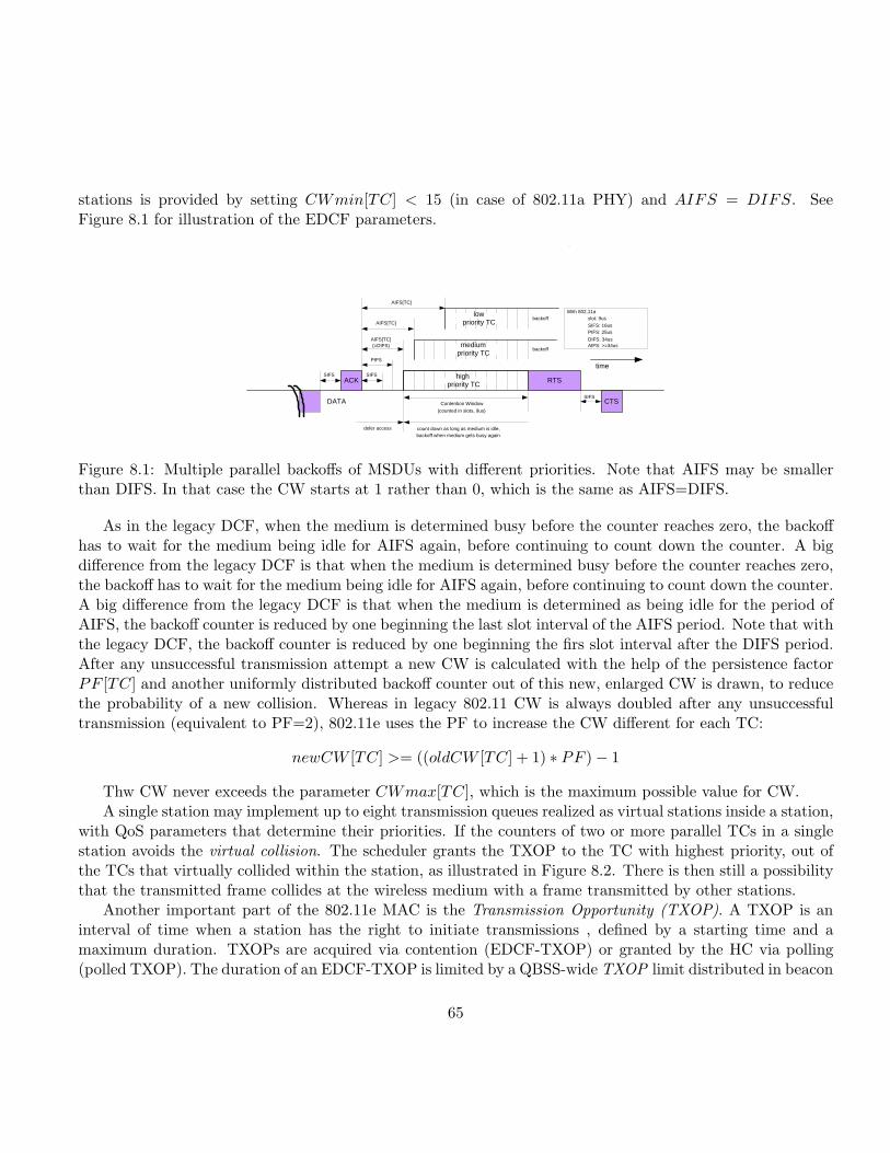
stations is provided by setting CWmin[TC] < 15 (in case of 802.11a PHY) and AIFS = DIFS. SeeFigure 8.1 for illustration of the EDCF parameters.
RTS
CTS
ACK
With 802.11a slot: 9us
SIFS: 16us PIFS: 25us
DIFS: 34us AIFS: >=34us medium
priority TC
low priority TC
high priority TC
DATA
SIFS SIFS
PIFS
AIFS[TC] (=DIFS)
AIFS[TC]
AIFS[TC]
Contention Window
(counted in slots, 9us)
SIFS
backoff
backoff
time
count down as long as medium is idle, backoff when medium gets busy again
defer access
Figure 8.1: Multiple parallel backoffs of MSDUs with different priorities. Note that AIFS may be smallerthan DIFS. In that case the CW starts at 1 rather than 0, which is the same as AIFS=DIFS.
As in the legacy DCF, when the medium is determined busy before the counter reaches zero, the backoffhas to wait for the medium being idle for AIFS again, before continuing to count down the counter. A bigdifference from the legacy DCF is that when the medium is determined busy before the counter reaches zero,the backoff has to wait for the medium being idle for AIFS again, before continuing to count down the counter.A big difference from the legacy DCF is that when the medium is determined as being idle for the period ofAIFS, the backoff counter is reduced by one beginning the last slot interval of the AIFS period. Note that withthe legacy DCF, the backoff counter is reduced by one beginning the firs slot interval after the DIFS period.After any unsuccessful transmission attempt a new CW is calculated with the help of the persistence factorPF [TC] and another uniformly distributed backoff counter out of this new, enlarged CW is drawn, to reducethe probability of a new collision. Whereas in legacy 802.11 CW is always doubled after any unsuccessfultransmission (equivalent to PF=2), 802.11e uses the PF to increase the CW different for each TC:
newCW [TC] >= ((oldCW [TC] + 1) ∗ PF )− 1
Thw CW never exceeds the parameter CWmax[TC], which is the maximum possible value for CW.A single station may implement up to eight transmission queues realized as virtual stations inside a station,
with QoS parameters that determine their priorities. If the counters of two or more parallel TCs in a singlestation avoids the virtual collision. The scheduler grants the TXOP to the TC with highest priority, out ofthe TCs that virtually collided within the station, as illustrated in Figure 8.2. There is then still a possibilitythat the transmitted frame collides at the wireless medium with a frame transmitted by other stations.
Another important part of the 802.11e MAC is the Transmission Opportunity (TXOP). A TXOP is aninterval of time when a station has the right to initiate transmissions , defined by a starting time and amaximum duration. TXOPs are acquired via contention (EDCF-TXOP) or granted by the HC via polling(polled TXOP). The duration of an EDCF-TXOP is limited by a QBSS-wide TXOP limit distributed in beacon
65
backoff
(DIFS) (15)
(2)
backoff
(AIFS) (CW)
(PF)
backoff
(DIFS) (15)
(2)
backoff
(DIFS) (15)
(2)
backoff
(DIFS) (15)
(2)
backoff
(DIFS) (15)
(2)
backoff
(DIFS) (15)
(2)
backoff
(DIFS) (15)
(2)
backoff
(DIFS) (15)
(2)
SCHEDULER (RESOLVES VIRTUAL COLLISIONS BY GRANTING TXOP TO HIGHEST PRIORITY)
Transmission Attempt
old new
Legacy: one priority
802.11e up to 8 independent backoff instances Higher priority Lower priority
TC 7 TC 6 TC 5 TC 4 TC 3 TC 0 TC 1 TC 2
Transmission Attempt
Figure 8.2: Virtual backoff of eight traffic categories: (1) left one: legacy DCF, close to EDCFwith AIFS=34us, CWmin=15, PF=2; (2) right one: EDCF with AIFS[TC]=¿ 34us, CWmin[TC]=0-255,PF[TC]=1-16.
frames. While the duration of a polled TXOP is specified by the duration field inside the poll frame. However,although the poll frame is a new frame as part of the upcoming 802.11e, also the legacy stations set their NAVsupon receiving this frame. More details about polled TXOP follow in the next subsection. The prioritizedchannel access is realized with the QoS parameters per TC, which include AIFS[TC], CWmin[TC], andPF[TC]. CWmax[TC] is optional. There are discussions to introduce priority dependent EDCF-TXOP[TC].The QoS parameters can be adapted over time by the HC, and will be announced periodically via the beaconframes. Protocol-related parameters are included in the beacon frame, which is transmitted at the beginningof each superframe.
8.2.2 Hybrid Coordination Function
The HCF extends the EDCF access rules. The HC may allocate TXOPs to itself to initiate MSDU Deliverieswhenever it wants, however, only after detecting the channel as being idle for PIFS, which is shorter thanDIFS. To give the HC priority over the EDCF, AIFS must be longer than PIFS and can therefore not have avalue smaller than DIFS.
During CP, each TXOP begins either when the medium is determined to be available under the EDCFrules, i.e., after AIFS plus backoff time, or when the station receives a special poll frame, the QoS CF-Pollfrom the HC. The QoS CF-Poll from the HC can be sent after a PIFS idle period without any backoff.Therefore the HC can issue polled TXOPs in the CP using its prioritized medium access. During the CFP,the starting time and maximum duration of each TXOP is specified by the HC, again using the QoS CF-Pollframes. Stations will not attempt to get medium access on its own during the CFP, so only the HC can grantTXOPs by sending QoS CF-Poll frames. The CFP ends after the time announced in the beacon frame or by
66
a CF-End frame from the HC.As part of 802.11e, an additional random access protocol that allows fast collision resolution is defined.
The HC polls stations for MSDU Delivery. For this, the HC requires information that has to be updated bythe polled stations form time to time. Controlled contention is a way for the HC to learn which station needsto be polled, at which times, and for which duration. The controlled contention mechanism allows stations torequest the allocation of polled TXOPs by sending resource requests, without contending with other (E)DCFtraffic. Each instance of controlled contention occurs during the controlled contention interval, which is startedwhen the HC sends a specific control frame. This control frame forces legacy stations to set their NAV untilthe end of the controlled contention interval, thus they remain silent during the controlled contention interval.The control frame defines a number of controlled contention opportunities (i.e., short intervals seperated bySIFS) and a filtering mask containing the TCs in which resource requests may be placed. Each station withqueued traffic for a TC matching the filtering mask chooses one opportunity interval and transmits a resourcerequest frame containing the requested TC and TXOP duration, or the queue size of the requested TC. Forfast collision resolution, the HC acknowledges the reception of request by generating a control frame with afeedback field so that the requesting stations can detect collisions during controlled contention.
The polled TXOPs are allocated with highest priority, without any CA, i.e. without any backoff beforethe poll. The polling scheme requires that there is one HC coordinating the channel, without any other HCin the range of this HC.
67

Bibliography
[1] B. O’Hara, A. Petrick, “IEEE 802.11 Handbook- A Designer‘s Companion”, IEEE Press.
[2] S. Mangold, L. Berlemann, G. Hiertz, “QoS Support as Utility for Coexisting Wireless LANs”, IPCNParis,2002.
[3] IEEE 802.11 WG, “Reference number ISO/IEC 8802-11:1999(E) IEEE Std 802.11, 1999 edition. Inter-national Standard [for] Information Technology-Telecommunications and information exchange betweensystems-Local and metropolitan area networks-Specific Requirements-Part 11: Wireless LAN MediumAccess Control (MAC) and Physical Layer (PHY) specifications,” 1999.
68