Embed Size (px)
Citation preview

IEEE JOURNAL OF SELECTED TOPICS IN QUANTUM ELECTRONICS, VOL. 23, NO. 5, SEPTEMBER/OCTOBER 2017 1900611
Recent Advances on Quantum-Dot-EnhancedLiquid-Crystal Displays
Haiwei Chen, Juan He, and Shin-Tson Wu, Fellow, IEEE
(Invited Paper)
Abstract—We review recent advances in quantum dot (QD)- en-hanced liquid crystal displays (LCDs), including material formu-lation, device configuration, and system integration. For the LCDsystem, we first compare the color gamut difference between thecommonly used Gaussian fitting method and that using real emis-sion spectra. Next, we investigate the Helmholtz–Kohlrausch effect.Our simulation results indicate that QD-enhanced LCD appears1.26X more efficient than organic light-emitting diode (OLED) dis-play due to its wider color gamut. Finally, two new trends for QD-LCDs are discussed: 1) replacing conventional color filters with aQD array, and 2) emerging quantum rod (QR)-enhanced backlight.Their inherent advantages, technical challenges, and potential so-lutions are presented. We believe the prime time for QD-enhancedLCDs is around the corner.
Index Terms—Color gamut, Quantum dot (QD), Quantum rod(QR), liquid crystal display (LCD).
I. INTRODUCTION
BACKLIGHT is a critical part of liquid crystal displays(LCDs), as it affects the color gamut, optical efficiency,
dynamic range, and viewing angle [1]–[4]. Presently, phosphor-converted white light-emitting diode (1pc-WLED) is the mainbacklight approach due to its high efficiency, long lifetime, lowcost, and simple optical configuration [5], [6]. However, itsbroad yellow spectrum generated by the YAG:Ce3+ phosphorleads to a relatively narrow (75%) color gamut, which fallsshort of the ever-growing demand for vivid colors. In the pasttwo decades, the color gamut evaluation metric has graduallyadvanced from sRGB to NTSC, and now to Rec. 2020 standard,whose coverage area in color space is nearly twice wider thanthat of sRGB [7]–[9]. As a result, advanced backlight technologyis in high demand.
Using discrete RGB LEDs is an effective way to expand thecolor gamut [5], [10]–[13], except its driving circuit complexityincreases [14], [15], and moreover, the high efficiency greenLED is still not available [16]. Another choice to widen colorgamut is to use two phosphor-converted WLED (2pc-WLED).The advantages of this approach include long term stability,
Manuscript received November 21, 2016; accepted January 3, 2017. Thiswork was supported in part by the a.u.Vista, Inc. and in part by the AFOSRunder contract FA9550-14-1-0279.
The authors are with the College of Optics and Photonics, University ofCentral Florida, Orlando, FL 32816 USA.
Color versions of one or more of the figures in this paper are available onlineat http://ieeexplore.ieee.org.
Digital Object Identifier 10.1109/JSTQE.2017.2649466
high efficiency, and low cost [17]–[20]. However, the narrowestfull width at half maximum (FWHM) of the green phosphor(β-sialon:Eu2+ ) is still as broad as 55 nm [20]–[22]. Whilefor red phosphor (K2SiF6:Mn4+ ) with five emission peaks, itsindividual FWHM is indeed quite narrow, but the average peakwavelength centers at ∼625 nm, which is not deep enough[23]–[25]. As a result, the RGB lights still show a relatively largeoverlap after passing through the color filters. These crosstalksgreatly reduce the color gamut.
Recently, quantum dot (QD)-enhanced backlight is emergingand it has found widespread applications because of followingoutstanding features: 1) its central emission wavelength can betuned by controlling the size of the nanoparticles, 2) its FWHMis around 20-30 nm, which is mainly determined by the sizeuniformity, 3) its photoluminescence efficiency is high, and 4)its device configuration is simple [26]–[34]. Briefly speaking,the QD backlight uses a blue LED to excite green/red colloidalnanoparticles, generating a white light with three well- separatedRGB peaks. Therefore, three highly saturated primary colorscould be obtained, leading to splendid image quality [31], [33].Several display manufacturers (e.g. Samsung, LG, Sony, TCL,etc.) have been adopting this promising technology. Sustainableefforts from both academic and industry would undoubtedlypave the way for QD-LCD’s great success in the near future.
In this review paper, we present recent advances of QD-LCDsfrom material formulation [Section II] to device configuration[Section III]. In Section IV, we discuss the display system’sperformance, including color gamut and optical efficiency. Anentoptic phenomenon called Helmholtz– Kohlrausch (H–K) ef-fect will be studied in detail. Finally in Section V, two newtrends for QD-LCDs will be highlighted: 1) replacing conven-tional color filters with a QD array, and 2) emerging quantumrod (QR)-enhanced backlight.
II. MATERIAL SYNTHESIS AND CHARACTERIZATIONS
Since the discovery in the 1980s, colloidal QDs have been ex-plored extensively for various applications [35]–[40]. In general,they are nanometer sized (e.g. 2 ∼ 10 nm) semiconductor par-ticles, which are mainly governed by the quantum confinementeffects. Unlike bulk material, these semiconductor nanoparticlesexhibit unique optical and electrical properties dictated by theirsize, shape, and the quantum physics that arises at the nanoscale[28], [29], [41].
1077-260X © 2017 IEEE. Personal use is permitted, but republication/redistribution requires IEEE permission.See http://www.ieee.org/publications standards/publications/rights/index.html for more information.
1900611 IEEE JOURNAL OF SELECTED TOPICS IN QUANTUM ELECTRONICS, VOL. 23, NO. 5, SEPTEMBER/OCTOBER 2017
Fig. 1. Schematic diagram of QD’s core-shell structure.
Briefly speaking, their desirable features can be summarizedinto three aspects: 1) large freedom for tailoring emission peaks.As Brus equation suggests [42]:
E∗ ∼= Eg +�π2
2R2
[1
me+
1mh
], (1)
where Eg is the bandgap of bulk semiconductor, R is the particleradius, and me and mh are the effective mass of electron andhole, respectively, the effective bandgap (and hence the fluores-cent light) of a QD system is dependent on the particle size.For example, a 2-nm diameter CdSe QD would emit blue light,while an 8-nm CdSe QD would emit in deep red. In principle,we can get any color in the visible region by simply controllingthe particle size during the synthesis process. 2) High purityemission colors. Through the sophisticated chemical synthesistechniques, QD’s particle size can be controlled precisely anduniformly [30]. The corresponding FWHM of Cd-based QDsis ∼30 nm. It is believed that 25-nm FWHM QDs in greenand red could be commercially available in the next few years[28]. With some modifications, 10-nm FWHM colloidal parti-cles have been reported in the form of platelets [43], [44]. Sucha narrow emission linewidth would undoubtedly produce an ex-ceedingly wide color gamut. 3) Excellent quantum yield andstability. This is attributed to the unique core-shell structure ofQDs, as Fig. 1 shows [37], [38]. Shells as well as the surround-ing organic ligands work as the protection layer and providenecessary processability. Both efficiency and lifetime would beenhanced compared to the core-only systems [45]–[47].
Various QD materials have been synthesized and studied [37],[38], [48]–[51]; they can be roughly divided into two groups:heavy metal-based QDs and heavy-metal-free QDs. Here, wechoose CdSe and InP as representatives from each group fordiscussing their characteristics.
A. Heavy Metal-Based QDs
II-VI semiconductor CdSe is the most developed and wellcharacterized QD material system [37], [38]. Its bulk bandgapis 1.73 eV (λ = 716 nm). According to Eq. (1), its emissionspectrum can be adjusted to cover the entire visible region bytailoring the particle size, as illustrated in Fig. 2(a) [36], [52].Meanwhile, with the mature hot-injection technique describedby Bawendi and co-workers [36]–[38], Cd-based QDs exhibitquite narrow FWHM (20 ∼ 30 nm) and super high luminescent
Fig. 2. (a) Potential emission spectral range of CdSe and InP QDs; (b) Typi-cal emission spectra for green and red quantum dots using CdSe (solid line)and InP (dashed line). Blue LED with emission peak λ = 450 nm is alsoshown here.
quantum efficiency (>95%). Fig. 2(b) depicts the typical emis-sion spectra for green and red CdSe QDs as well as a highpower InGaN blue LED. With commercially available color fil-ters, 90% Rec. 2020 color gamut has been realized [33], [53],[54]. Such a high quality QD material seems to be a perfectchoice for display applications. Indeed, Cd-based QDs have al-ready been employed in some commercial products. However,owing to its toxicity, there is increasing demand for manufactur-ers to eliminate cadmium, along with other heavy metals, fromconsumer products. For example, in 2003 the European Unionissued a directive known as the Restriction of Hazardous Sub-stances (RoHS) [55], where the maximum cadmium content islimited to 100 ppm in any consumer electronic product. There-fore, heavy metal-free or low Cd content QDs become the newtrends for future display applications [56].
B. Heavy Metal-Free QDs
Among several candidates for Cd-free QDs, InP has beenidentified as the most viable alternative for the visible light[48], [49], [57]–[60]. Its bandgap for bulk material is 1.35 eV,which is smaller than that of CdSe. Thus, to reach the sameemission wavelength, the core size of InP dots has to be smallerthan that of CdSe [Fig. 2(a)]. Smaller bandgap and smaller par-ticle size lead to much stronger confinement effect. Thus, theemission spectrum of InP QDs is more susceptible to particlesize variation [48]. As a result, its FWHM is somewhat broader(>40 nm), as shown in Fig. 2(b), corresponding to 70−80%Rec. 2020 color gamut, depending on the color filters employed.What’s more, its quantum yield and stability are slightly inferior

CHEN et al.: RECENT ADVANCES ON QUANTUM-DOT-ENHANCED LIQUID-CRYSTAL DISPLAYS 1900611
Fig. 3. Schematic diagram for three different device geometries implementingQD mixtures. (a) QD is placed within an LED package. (b) QD is placed betweenLED and light guide plate, or known as quantum rail. (c) QD is placed on thetop surface of light guide plate, or known as quantum dot enhancement film(QDEF). (LGP: light guide plate).
to those of Cd-based QDs, mostly due to the immature chemicalsynthesis method [56], [61]–[64]. In 2015, Nanoco claimed tohave improved the InP lifetime to over 30,000 hours using their“molecular seeding” synthesis method [63]. Once their FWHMcan be further reduced, InP QDs will be more attractive for dis-play applications. As a matter of fact, such a Cd-free backlighthas already been widely used in Samsung’s TV products, andit exhibits excellent performances including wide color gamutand long lifetime [65].
Another thing worth mentioning here is, to be compliant toRoHS regulations, Nanosys proposed a “greener” QD systemby combining the Cd-free and low Cd-based QDs [64]. Thishybrid approach not only retains 90% Rec. 2020 color gamutbut also complies with the RoHS regulation.
So far, RoHS sets the upper limit for heavy metal-based QDs.Although InP is not currently on the list, it could be reevaluatedin the future. As a result, other environmentally friendly QDmaterials need to be developed.
III. DEVICE CONFIGURATIONS
Three QD backlight geometries have been commonly used[28]: they are “on-chip”, “on-edge” and “on-surface”, as Fig. 3depicts. Each design has its own pros and cons, and should bechosen carefully based on different applications.
A. On-Chip Geometry
This design consumes the least amount of QD material, andis cost effective. Also, it is fully compatible to current backlightunit, leading to much simpler optical design [26], [66]. Whatwe need is to simply replace the phosphors with QD mixturesas the energy down-conversion layer, within an LED package,
Fig. 4. Schematic diagram of QD on-chip geometry.
Fig. 5. Schematic diagram of QD on-edge geometry (i.e. QD rail).
as shown in Fig. 4(a). However, due to the high flux and highLED junction temperature (∼150 °C), the lifetime and stabilityof QDs could be sacrificed significantly [33], [67]. Another con-cern is the packaging issue, as QDs are highly sensitive to watervapor and oxygen. Hermetic sealing is necessary, which in turnincreases the total cost and design complexity [28]. Neverthe-less, some progress has been achieved. As reported by PacificLighting in 2014 [66], their on-chip testing results of QDs showno clear degradations within 3000 hours under a flux condi-tion of 52W/cm2 at 85 °C and 85% relative humidity. Similarresults were reported by Sun et al. in 2016 [68].
B. On-Edge Geometry
Because the on-chip design is not yet mature for practicaldisplay applications, the on-edge geometry becomes a suitablealternative, especially for large size TVs [33]. In fact, Sony re-leased its 55” QD TV using such configuration in 2013 [69].Compared to on-chip design, QD rail’s lifetime is much im-proved because it is located further away from the blue LED.Also, the consumption of QD material is still acceptable. How-ever, assembly is a potential issue, as Fig. 5 depicts. QD railis first mounted into a mixing cup, and then sandwiched be-tween the blue LED bar and the light guide plate (LGP) [70].Here, the mixing cup is a mechanical structure, typically moldedfrom a highly reflective plastic. It can hold the QD rail as abracket, while directing the emitted light towards the LGP. Forsuch a configuration, both optical efficiency and color unifor-mity should be considered together. Detailed discussions forthe opto-mechanical optimizations have been reported in [70].Briefly speaking, there exists an inherent trade-off between ef-ficiency and color uniformity, so that several parameters need
1900611 IEEE JOURNAL OF SELECTED TOPICS IN QUANTUM ELECTRONICS, VOL. 23, NO. 5, SEPTEMBER/OCTOBER 2017
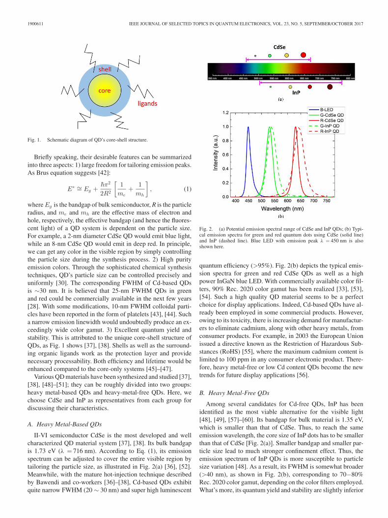
Fig. 6. (a) Schematic diagram and (b) photographic image of QD on-surfacegeometry (i.e. QDEF).
to be carefully designed, like scattering particles concentrationin QD matrix, distance between QD rail and LGP, QD rail’ssize, etc.
C. On-Surface Geometry
This is the most commonly used geometry, also known asquantum dot enhancement film (QDEF) [71]. It is placed abovethe LGP [Fig. 3(c)], decoupled from the LED heat source spa-tially. As a result, the resultant operating temperature shouldbe close to the room temperature. Both reliability and long-term stability are enhanced significantly. In fact, a lifetime over30,000 hours has been achieved by the accelerated aging experi-ments [72]. Fig. 6(a) shows a sketched structure of QDEF, whichcomprises three layers – two plastic barrier films sandwiching alayer of quantum dots suspended in a polymer matrix [73], [74].The barrier film for QDEF is optically clear to let light passthrough, flexible for rolling and thin to allow a slim device pro-file, while prevents degradation from oxygen and moisture in apackage. QD layer contains trillions of red- and green-emittingquantum dots, yielding yellow appearance for QDEF, as shownin Fig. 6(b). One drawback of QDEF is the massive materialconsumption, especially for large screen TVs. As the capacityof QDEF keeps growing, the cost should decrease gradually inthe near future.
IV. SYSTEM PERFORMANCE
After introducing QD materials formulation and device con-figuration, next let us analyze the optical performance of an LCDsystem [27], [31]. Fig. 7 shows the system configuration of atypical LCD panel [75]. The incident light Sin(λ) is split intothree channels: red (R), green (G) and blue (B) corresponding toRGB color filters. Then they pass through the thin film transistor(TFT) backplane, LC layer, and color filter array successively.Finally, the RGB channels mix together and transmit out of theLCD panel with spectrum given as:
Sout(λ) = Sout,R (λ) + Sout,G (λ) + Sout,B (λ). (2)
Fig. 7. System configuration of a typical LCD panel. (LC: liquid crystal; TFT:thin-film transistor).
Fig. 8. Gaussian fitting of the white light spectrum using a blue LED to excitegreen/red CdSe QDs.
As usual, two metrics are defined here to evaluate the back-light performance: total light efficiency (TLE) and color gamut.
TLE =683 lm
W
∫Sout(λ)V (λ)dλ∫Sin(λ)dλ
. (3)
TLE represents how much input light transmits through theLCD panel and finally gets converted to the brightness per-ceived by the human eye. Here, V(λ) stands for the human eyesensitivity function [76]. Unless otherwise stated, all the TLEspresented here are evaluated at the same white point D65.
As for color gamut, three color coordinates could be calcu-lated using the output spectrum for each channel, i.e. Sout,R (λ),Sout,G (λ), and Sout,B (λ). Then the triangular area defined bythe color coordinates of the RGB primaries (the color gamut ofthe system) is compared to the standard gamut, like NTSC orRec. 2020. The color gamut of the system can then be describedas a percent coverage or percent area for a gamut [54].
A. Gaussian Fitting Effect
As shown in Fig. 2(b), QD emission spectrum is Gaussian-like, and so is blue LED. Thus Gaussian fitting is commonlyconducted to extract the peak wavelength and FWHM [Fig. 8].To make it simple, in some cases, the fitted curves are employed

CHEN et al.: RECENT ADVANCES ON QUANTUM-DOT-ENHANCED LIQUID-CRYSTAL DISPLAYS 1900611
Fig. 9. (a)-(c) Calculated output spectra for blue, green and red primary colorsafter LC layer and color filters (CF-1).
directly into further calculations and optimizations for colorgamut and other metrics by neglecting the fitting discrepancy[27], [31], [54]. Here, we discuss this Gaussian fitting effect andinvestigate how much it influences the final color performance.
Let us use blue LED and green and red CdSe QDs,as Fig. 8 depicts, as examples. The fitted peak wave-lengths for three primary colors are λB = 450.4 nm, λG =
TABLE ICALCULATED COLOR GAMUT AND TOTAL LIGHT EFFICIENCY
FOR SPECTRUM WITH AND WITHOUT GAUSSIAN FITTING
Rec. 2020 TLE (lm/W)
CIE 1931 CIE 1976
w/ Gaussian Fitting 87.7% 88.1% 26.2w/o Gaussian Fitting 82.4% 76.2% 28.0
529.5 nm, and λR = 630.8 nm. The corresponding FWHM isΔλB = 20.3 nm, ΔλG = 30.5 nm, and ΔλR = 24.4 nm byGaussian fittings. Clearly, some discrepancies in the tails areobserved, especially for blue LED. For R/G QDs, there ex-ists longer emission tails than Gaussian function could predict.Such problem is more noticeable for the InP QDs, as shownin Fig. 2(b). During our calculations, commercial color filters(CF-1) are employed [27], whose transmission spectra will beshown later.
Fig. 9 shows the calculated output spectrum for each primarycolor after LC layer and CF-1. As expected, the spectra withGaussian fitting exhibit much weaker color crosstalk; less lightleakage results from the emission tails. Whereas for real spec-trum without Gaussian fitting, there is a noticeable bump in theblue and green regions, which would deteriorate the color purityand shrink the color gamut.
The color gamut shrinkage can be visualized more clearly inFig. 10. In both color spaces, CIE 1931 and CIE 1976, greenand blue coordinates with Gaussian fitting expand outwards,leading to a much wider color gamut than that of real spectrum.The simulated results are listed in Table I. In CIE 1931, the colorgamut with Gaussian fittings is 5.3% wider than that using thereal spectrum. While in CIE 1976, this difference is increased to11.9%. This discrepancy is too large to be neglected. Therefore,we should use the real spectrum instead of using fitted curveswhen carrying out future calculations. It is worth mentioninghere: due to the light leakage shown in Fig. 9, continuing todecrease the FWHM of QDs, e.g. from 30 nm to 20 nm and thento 10 nm, will not improve the color gamut noticeably. Rather,it will eventually lead to a saturated color gamut.
B. Color Filter Effect
Besides backlight, color filters also play an important rolein determining LCD’s color performance. Fig. 11 shows thetransmission spectra of two commercial color filters: CF-1 hashigher transmittance but larger overlap between blue/green andgreen/red regions, while CF-2 has less color crosstalk, butthe transmittance is lower, especially in the blue and greenregions.
Fig. 12 shows the calculated color gamut and light efficiency.For comparison purpose, besides CdSe and InP QDs, we alsoinclude three other light sources: 1) cold cathode fluorescentlamp (CCFL), 2) yellow phosphor-converted white LED (1pc-WLED), and 3) green and red phosphor-converted white LED(2pc-WLED). Their emission spectra are obtained from [20] and[77]. Moreover, an OLED is also included here for comparison

1900611 IEEE JOURNAL OF SELECTED TOPICS IN QUANTUM ELECTRONICS, VOL. 23, NO. 5, SEPTEMBER/OCTOBER 2017
Fig. 10. Simulated color gamut in (a) CIE 1931 and (b) CIE 1976 color space.
Fig. 11. Transmission spectra of two commercial color filters.
Fig. 12. TLE versus color gamut using (a) CF-1 and (b) CF-2. (Here, colorgamut in CIE 1931 color space is employed).
[78], but its TLE is not representative because the definition foran emissive OLED’s light efficiency is totally different from anon-emissive LCD. From Fig. 12, the Cd-based QD-enhancedbacklight shows the best performance in terms of light effi-ciency and color gamut. While 2pc-WLED, OLED, and InP QDhold a similar electro-optic performance. This is understandablebecause they all exhibit similar FWHM emission spectra (40 nm∼ 50 nm).
When comparing Fig. 12(a) with (b), we find an interestingphenomenon. Firstly, for all the backlight sources, the opticalefficiency is drastically reduced when CF-2 color filters (i.e.narrower bandwidth but less efficient) are used. But for colorgamut, the effect is reversed. For CCFL and 1pc-WLED, the im-provement using narrower CF-2 is as large as 13% in Rec. 2020,but for 2pc-WLED and InP QD this improvement is only ∼9%.For the CdSe QD, its color gamut only increases 6% in Rec.2020, indicating that the backlight with purer emission peaksis less dependent on the color filters. Therefore, QD backlightwould allow the use of broader band CFs (CF-1) for achievingbalanced efficiency and color gamut.

CHEN et al.: RECENT ADVANCES ON QUANTUM-DOT-ENHANCED LIQUID-CRYSTAL DISPLAYS 1900611
Fig. 13. Isoquality curves of the perceived quality metric (or known as displayquality score).
C. Helmholtz–Kohlrausch Effect
Wide color gamut not only helps produce vivid colors but alsohelps reduce power consumption. This is due to the so-calledHelmholtz–Kohlrausch (H-K) effect, in which a display withmore saturated color is perceived to be brighter [79]–[82]. It is anentoptic phenomenon. As Fig. 13 depicts, the perceived qualitymetric (PQM) [83], or known as display quality score (DQS)[84], is proposed to describe the display quality quantitatively.This figure describes how display quality is affected by bothluminance and color gamut. In this isoquality figure, the line atthe upper right corner represents better perceived quality, andpoints on the same line is considered as equal quality. Theselines are achieved using Adobe RGB in CIE 1976 color space.
Using the backlight sources described above, we could eas-ily mark their points in this PQM (or DQS) figure. Here, wefocus on the CdSe QD and OLED’s performances; the 2pc-WLED and InP QD exhibit similar color gamut as OLED. Incomparison, CdSe QD shows much larger color gamut thanOLED (129% vs. 106% Adobe RGE). When it comes to the per-ceived image quality, QD-LCD would be 1.26X more efficientthan OLED (347 cd/ m2 vs. 438 cd/ m2). Similar phenomenonhas been reported when comparing OLED with 1pc-WLEDbased LCD [85], or in LED projectors [86], [87]. Fig. 14 illus-trates this effect more clearly. For the same luminance intensity(347 cd/ m2) [Fig. 14(a)], QD-LCD looks better than OLEDdue to its more saturated colors. To possess similar quality, weneed to raise the luminance intensity of an OLED to 438 cd/ m2
[Fig. 14(b)].
V. FUTURE TRENDS
Because QD-enhanced backlight offers more saturated colors,and higher optical efficiency than conventional WLED, it hasbeen widely used in high-end TVs, monitors, and pads. Lately,some advanced QD-based technologies are being actively inves-
Fig. 14. Illustration of perceived image quality for OLED and QD-LCD.
tigated. Here we only highlight two of them, and discuss theirinherent advantages, issues and potential solutions.
A. Quantum Dot Array for Color Filters
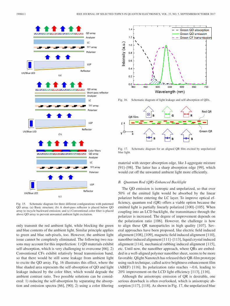
In conventional LCD panels, over 2/3 of the incident backlightis absorbed by the color filters (CFs) [75]. Thus, to improveoptical efficiency, one approach is to remove or replace CFs.As an excellent energy down-conversion material, QD holdsthis promise. Fig. 15(a) depicts the proposed structure, where apatterned QD array is placed above the LC layer. A UV-LEDor blue LED array is employed as the pumping source to excitethe RGB QDs. Since there is no spatial CFs, the light efficiencyshould be tripled. Another implicit advantage is faster responsetime. This is because only blue light traverses through the LClayer, we can use a thinner cell gap to achieve the requiredphase retardation. A thinner LC cell leads to a faster responsetime. Meanwhile, viewing angle is greatly widened, owing tothe isotropic emission of QDs. In 2016, Chen et al. combinedQD array with a TN LC panel to achieve excellent performance,such as fast response time (τon + τoff < 3ms), wide viewingangle, and increased optical efficiency [88]. In their design, adeep blue LED with λ = 410 nm was employed to excite theRGB QD array.
The design concept of patterned QD array is intriguing, butsome technical issues remain to be overcome. First, the back-ward emission of QD array should be recycled, otherwise halfof the emitted light would be lost. A band-pass reflector pro-vides a possible solution [Fig. 15(b)] as it transmits blue light,while reflecting green and red. This way, all the QD emissionscan be fully utilized [89]. Such design is particularly attractivefor virtual reality (VR) displays. In an immersed environment,there is no ambient light to excite the QD array.
If the display is exposed to an ambient light, then anotherserious concern would arise. Besides blue backlight, green andred QDs could be excited by the short-wavelength ambient lightas well. As a result, the ambient contrast ratio would degradesubstantially. To prevent this from happening, we can place aconventional color filter array above the QD layer to block theunwanted ambient light, as shown in Fig. 15(c) [89]. Let usexamine the red pixels first. Under such condition, the red CFs
1900611 IEEE JOURNAL OF SELECTED TOPICS IN QUANTUM ELECTRONICS, VOL. 23, NO. 5, SEPTEMBER/OCTOBER 2017
Fig. 15. Schematic diagram for three different configurations with patternedQD array. (a) Basic structure; (b) A short-pass reflector is placed below QDarray to recycle backward emission; and (c) Conventional color filter is placedabove QD array to prevent unwanted ambient light excitation.
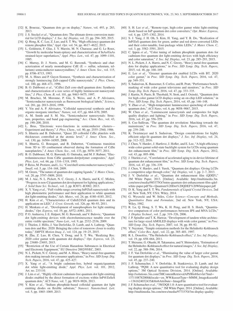
only transmit the red ambient light, while blocking the greenand blue contents of the ambient light. Similar principle appliesto green and blue sub-pixels, too. However, the ambient lightissue cannot be completely eliminated. The following two rea-sons may account for this imperfection: 1) QD materials exhibitself-absorption, which is very challenging to overcome [66]. 2)Conventional CFs exhibit relatively broad transmission band,so that there would be still some leakage from ambient lightto excite the QD array. Fig. 16 illustrates this effect, where theblue shaded area represents the self-absorption of QD and lightleakage induced by the color filter, which would degrade theambient contrast ratio. Two possible solutions can be consid-ered: 1) reducing the self-absorption by separating the absorp-tion and emission spectra [66], [90]; 2) using a color filtering
Fig. 16. Schematic diagram of light leakage and self-absorption of QDs.
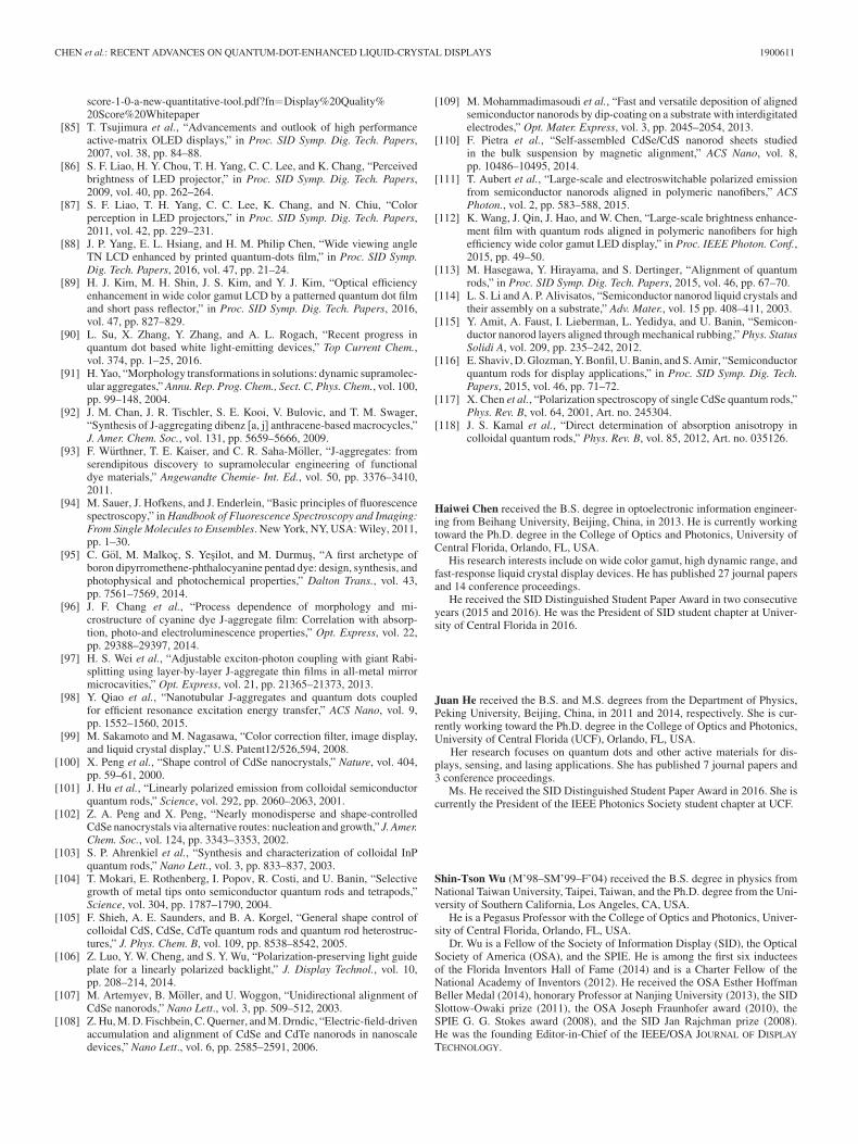
Fig. 17. Schematic diagram for an aligned QR film excited by unpolarizedblue light.
material with steeper absorption edge, like J-aggregate mixture[91]–[98]. The latter has a sharp absorption edge [99], whichwould cut off the unwanted ambient light more efficiently.
B. Quantum Rod (QR)-Enhanced Backlight
The QD emission is isotropic and unpolarized, so that over50% of the emitted light would be absorbed by the linearpolarizer before entering the LC layer. To improve optical ef-ficiency, quantum rod (QR) offers a viable option because theemitted light is partially linearly polarized [100]–[105]. Whencoupling into an LCD backlight, the transmittance through thepolarizer is increased. The degree of improvement depends onthe polarization ratio [106]. However, the challenge is howto align these QR nanoparticles in high quality [107]. Sev-eral approaches have been proposed, like electric field inducedalignment [108], [109], magnetic field induced alignment [110],nanofiber induced alignment [111]–[113], liquid crystal inducedalignment [114], mechanical rubbing induced alignment [115],etc. Until now, the nanofiber approach, where QRs are embed-ded in a well-aligned polymer nanofiber sheet, seems to be morefavorable. Qlight Nanotech has released their QR-film prototypeusing such technique, called active brightness enhancement film(ABEF) [116]. Its polarization ratio reaches ∼0.6, leading to20% improvement on the LCD light efficiency [113], [116].
Although the anisotropic emission of QR is desirable, oneserious drawback is often overlooked, which is anisotropic ab-sorption [117], [118]. As shown in Fig. 17, the unpolarized blue

CHEN et al.: RECENT ADVANCES ON QUANTUM-DOT-ENHANCED LIQUID-CRYSTAL DISPLAYS 1900611
light excites well-aligned green and red QRs. As expected, apartially linearly polarized green/red light is generated. Herewe assume the larger dipole moment of QR nanoparticle isaligned in x-axis, which determines the preferred emission di-rection. But at the same time, the absorption along x-axis wouldbe also much stronger than that of y-axis, leading to partiallylinearly polarized blue light. The polarization direction of theoutgoing blue light is orthogonal to that of emitted green/redbeams. In this case, a linear polarizer could easily deterioratethe color balance by absorbing either blue or green/red light.This polarization mismatch problem should be solved beforeQR-enhanced backlight can find widespread applications.
VI. CONCLUSION
We have briefly reviewed the recent progress of QD- en-hanced LCDs. From material viewpoint, Cd-based QDs showthe best performance, including narrow FWHM (∼25 nm), highquantum efficiency (>95%) and long-term stability (>30,000hours). Meanwhile, heavy metal-free QDs are emerging: InPQDs are catching up in lifetime and quantum efficiency, butits FWHM needs further improvement. Regarding the deviceconfiguration, QDEF and QD rail have been commercialized,while the on-chip approach is still awaiting for the lifetime andcompliant packaging issues to be resolved. As for the systemlevel, we first investigate the effect of Gaussian fitting in thecolor gamut calculations, and observe a noticeable difference.Compared to other backlight sources, QD technology exhibitssuperior performance, like higher efficiency and wider colorgamut. When considering the H-K effect, QD-enhanced LCDis 1.26X more efficient than OLED due to the more saturatedprimary colors. New trends for QD-LCDs are also highlighted.One is to use QD array to replace conventional color filters.Some specific structure designs are needed in order to utilizethe backward emission and prevent ambient light excitation.Another one is quantum rod enhanced backlight. It exhibitsanisotropic emission, but also anisotropic absorption. The lattercauses polarization mismatch between the transmitted blue lightand the photoluminescent green/red light. The development ofQD-LCD is still undergoing very actively. We believe the primetime for QD-enhanced LCDs is around the corner.
ACKNOWLEDGMENT
The authors would like to thank R. Zhu and G. Tan for help-ful discussions, Y. Huang for providing her photograph, andDr. Y.-T. Lu of EFUN Technology (Taiwan) for providing theQDEF sample shown in Fig. 6(b).
REFERENCES
[1] S. Kobayashi, S. Mikoshiba, and S. Lim, LCD Backlights. New York,NY, USA: Wiley, 2009.
[2] T. Okumura, A. Tagaya, Y. Koike, M. Horiguchi, and H. Suzuki, “Highly-efficient backlight for liquid crystal display having no optical films,”Appl. Phys. Lett., vol. 83, pp. 2515–2517, 2003.
[3] K. Kalantar, “Modified functional light-guide plate for backlightingtransmissive LCDs,” J. Soc. Inf. Display, vol. 11, pp. 641–645, 2003.
[4] D. Feng, Y. Yan, X. Yang, G. Jin, and S. Fan, “Novel integrated light-guide plates for liquid crystal display backlight,” J. Opt. A, Pure Appl.Opt., vol. 7, pp. 111–117, 2005.
[5] M. Anandam, “Progress of LED backlights for LCDs,” J. Soc. Inf.Display, vol. 16, pp. 287–310, 2008.
[6] H. T. Huang, Y. P. Huang, and C. C. Tsai, “Planar lighting system usingarray of blue LEDs to excite yellow remote phosphor film,” J. DisplayTechnol., vol. 7, pp. 44–51, 2011.
[7] “Parameter values for the HDTV standards for production and interna-tional programme Exchange,” ITU Recommendation BT.709-6, 2015.
[8] “Parameter values for ultra-high definition television systems for pro-duction and international programme exchange,” ITU RecommendationBT.2020-2, 2015.
[9] K. Masaoka, Y. Nishida, M. Sugawara, and E. Nakasu, “Design of pri-maries for a wide-gamut television colorimetry,” IEEE Trans. Broadcast.,vol. 56, no. 4, pp. 452–457, Dec. 2010.
[10] G. Harbers and C. Hoelen, “High performance LCD backlighting usinghigh intensity red, green and blue light emitting diodes,” in Proc. SIDSymp. Dig. Tech. Papers, 2001, vol. 32, pp. 702–705.
[11] R. S. West et al., “High brightness direct LED backlight for LCD TV,”in Proc. SID Symp. Dig. Tech. Papers, 2003, vol. 34, pp. 1262–1265.
[12] W. Folkerts, “LED backlighting concepts with high flux LEDs,” in Proc.SID Symp. Dig. Tech. Papers, 2004, vol. 35, pp. 1226–1229.
[13] R. B. Lu, S. Gauza, and S. T. Wu, “LED-lit LCD TVs,” Mol. Cryst. Liq.Cryst., vol. 488, pp. 246–259, 2008.
[14] H. J. Chiu and S. J. Cheng, “LED backlight driving system for large-scaleLCD panels,” IEEE Trans. Ind. Electron., vol. 54, no. 5, pp. 2751–2760,Oct. 2007.
[15] C. Y. Wu, T. F. Wu, J. R. Tsai, Y. M. Chen, and C. C. Chen, “MultistringLED backlight driving system for LCD panels with color sequentialdisplay and area control,” IEEE Trans. Ind. Electron., vol. 55, no. 10,pp.3791–3800, Oct. 2008.
[16] E. F. Schubert, T. Gessmann, and J. K. Kim, Light Emitting Diodes.New York, NY, USA: Wiley, 2005.
[17] R. J. Xie, N. Hirosaki, and T. Takeda, “Wide color gamut backlight forliquid crystal displays using three-band phosphor-converted white light-emitting diodes,” Appl. Phys. Express, vol. 2, 2009, Art. no. 022401.
[18] Y. Ito, T. Hori, T. Kusunoki, H. Nomura, and H. Kondo, “A phosphorsheet and a backlight system providing wider color gamut for LCDs,”J. Soc. Inf. Display, vol. 22, pp. 419–428, 2014.
[19] J. H. Oh, H. Kang, M. Ko, and Y. R. Do, “Analysis of wide color gamutof green/red bilayered freestanding phosphor film-capped white LEDsfor LCD backlight,” Opt. Express, vol. 23, pp. A791–A804, 2015.
[20] L. Wang et al., “Highly efficient narrow-band green and red phosphorsenabling wider color-gamut LED backlight for more brilliant displays,”Opt. Express, vol. 23, pp. 28707–28717, 2015.
[21] N. Hirosaki et al., “Characterization and properties of green-emitting β-SiAlON:Eu2+ powder phosphors for white light-emitting diodes,” Appl.Phys. Lett., vol. 86, 2009, Art. no. 211905.
[22] R. J. Xie, N. Hirosaki, H. L. Li, Y. Q. Li, and M. Mitomo, “Synthesisand photoluminescence properties of β-sialon:Eu2+ (Si6-zAlzOzN8-z:Eu2+) - A promising green oxynitride phosphor for white light-emitting diodes,” J. Electrochem. Soc., vol. 154, pp. J314–J319, 2008.
[23] S. Adachi and T. Takahashi, “Direct synthesis and properties ofK2SiF6:Mn4+ phosphor by wet chemical etching of Si wafer,” J. Appl.Phys., vol. 104, 2008, Art. no. 023512.
[24] T. Takahashi and S. Adachi, “Synthesis of K2SiF6:Mn4+ red phosphorfrom silica glasses by wet chemical etching in HF/KMnO4 solution,”Electrochem. Solid State Lett., vol. 12, pp. J69–J71, 2009.
[25] J. E. Murphy, F. Garcia-Santamaria, A. A. Setlur, and S. Sista, “PFS,K2SiF6:Mn4+: The red-line emitting LED phosphor behind GE’s Tri-Gain TechnologyTM platform,” in Proc. SID Symp. Dig. Tech. Papers,2015, vol. 46, pp. 927–930.
[26] E. Jang et al., “White-light-emitting diodes with quantum dot color con-verters for display backlights,” Adv. Mater., vol. 22, pp. 3076–3080,2010.
[27] Z. Luo, Y. Chen, and S. T. Wu, “Wide color gamut LCD with a quantumdot backlight,” Opt. Express, vol. 21, pp. 26269–26284, 2013.
[28] S. Coe-Sullivan, W. Liu, P. Allen, and J. S. Steckel, “Quantum dots forLED downconversion in display applications,” ECS J. Solid State Sci.Technol., vol. 2, pp. R3026–R3030, 2013.
[29] Y. Shirasaki, G. J. Supran, M. G. Bawendi, and V. Bulovic, “Emergenceof colloidal quantum-dot light-emitting technologies,” Nat. Photon.,vol. 7, pp. 13–23, 2013.
[30] J. S. Steckel et al., “Quantum dot manufacturing requirements for thehigh volume LCD market,” in Proc. SID Symp. Dig. Tech. Papers, 2013,vol. 44, pp. 943–945.
[31] Z. Luo, D. Xu, and S. T. Wu, “Emerging quantum-dots-enhanced LCDs,”J. Display Technol., vol. 10, pp. 526–539, 2014.
1900611 IEEE JOURNAL OF SELECTED TOPICS IN QUANTUM ELECTRONICS, VOL. 23, NO. 5, SEPTEMBER/OCTOBER 2017
[32] K. Bourzac, “Quantum dots go on display,” Nature, vol. 493, p. 283,2013.
[33] J. S. Steckel et al., “Quantum dots: The ultimate down-conversion mate-rial for LCD displays,” J. Soc. Inf. Display, vol. 23, pp. 294–305, 2015.
[34] Q. Hong, K. C. Lee, Z. Luo, and S. T. Wu, “High-efficiency quantum dotremote phosphor film,” Appl. Opt. vol. 54, pp. 4617–4622, 2015.
[35] L. Goldstein, F. Glas, J. Y. Marzin, M. N. Charasse, and G. Le Roux,“Growth by molecular beam epitaxy and characterization of InAs/GaAsstrained-layer superlattices,” Appl. Phys. Lett., vol. 47, pp. 1099–1101,1985.
[36] C. Murray, D. J. Norris, and M. G. Bawendi, “Synthesis and char-acterization of nearly monodisperse CdE (E = sulfur, selenium, tel-lurium) semiconductor nanocrystallites,” J. Amer. Chem. Soc., vol. 115,pp. 8706–8715, 1993.
[37] M. A. Hines and P. Guyot-Sionnest, “Synthesis and characterization ofstrongly luminescing ZnS-capped CdSe nanocrystals,” J. Phys. Chem.,vol. 100, pp. 468–471, 1996.
[38] B. O. Dabbousi et al., “(CdSe) ZnS core-shell quantum dots: Synthesisand characterization of a size series of highly luminescent nanocrystal-lites,” J. Phys. Chem. B, vol. 101, pp. 9463–9475, 1997.
[39] M. Bruchez, M. Moronne, P. Gin, S. Weiss, and A. P. Alivisatos,“Semiconductor nanocrystals as fluorescent biological labels,” Science,vol. 281, pp. 2013–2016, 1998.
[40] Y. Yin and A. P. Alivisatos, “Colloidal nanocrystal synthesis and theorganic-inorganic interface,” Nature, vol. 437, pp. 664–670, 2005.
[41] A. M. Smith and S. M. Nie, “Semiconductor nanocrystals: Struc-ture, properties, and band gap engineering,” Acc. Chem. Res., vol. 43,pp. 190–200, 2010.
[42] L. Brus, “Electronic wave-functions in semiconductor clusters—Experiment and theory,” J. Phys. Chem., vol. 90, pp. 2555–2560, 1986.
[43] S. Ithurria and B. Dubertret, “Quasi 2D colloidal CdSe platelets withthicknesses controlled at the atomic level,” J. Amer. Chem. Soc.,vol. 130, pp. 16504–16505, 2008.
[44] S. Ithurria, G. Bousquet, and B. Dubertret, “Continuous transitionfrom 3D to 1D confinement observed during the formation of CdSenanoplatelets,” J. Amer. Chem. Soc., vol. 133, pp. 3070–3077, 2011.
[45] B. O. Dabbousi, M. G. Bawendi, O. Onitsuka, and M. F. Rubner, “Elec-troluminescence from CdSe quantum-dot/polymer composites,” Appl.Phys. Lett., vol. 66, pp. 1316–1318, 1995.
[46] P. Reiss, M. Protiere, and L. Li, “Core/shell semiconductor nanocrystals,”Small, vol. 5, pp. 154–168, 2009.
[47] M. Green, “The nature of quantum dot capping ligands,” J. Mater. Chem.,vol. 20, pp. 5797–5809, 2010.
[48] M. J. Anc, N. L. Pickett, N. C. Gresty, J. A. Harris, and K. C. Mishra,“Progress in non-Cd quantum dot development for lighting applications,”J. Solid State Sci. Technol., vol. 2, pp. R3071–R3082, 2013.
[49] X. Y. Yang et al., “Full visible range covering InP/ZnS nanocrystals withhigh photometric performance and their application to white quantumdot light-emitting diodes,” Adv. Mater., vol. 24, pp. 4180–4185, 2012.
[50] H. Kim et al., “Characteristics of CuInS2/ZnS quantum dots and itsapplication on LED,” J. Cryst. Growth, vol. 326, pp. 90–93, 2011.
[51] H. Menkara et al., “Development of nanophosphors for light emittingdiodes,” Opt. Express, vol. 19, pp. A972–A981, 2011.
[52] P. O. Anikeeva, J. E. Halpert, M. G. Bawendi, and V. Bulovic, “Quantumdot light-emitting devices with electroluminescence tunable over theentire visible spectrum,” Nano Lett., vol. 9, pp. 2532–2536, 2009.
[53] J. Thielen, J. Hillis, J. Van Derlofske, D. Lamb, and A. Lathrop, “Quan-tum dots and Rec. 2020: Bringing the color of tomorrow closer to realitytoday,” SMPTE Motion Imag. J., vol. 124, pp. 19–25, 2015.
[54] R. Zhu, Z. Luo, H. Chen, Y. Dong, and S. T. Wu, “Realizing Rec.2020 color gamut with quantum dot displays,” Opt. Express, vol. 23,pp. 23680–23693, 2015.
[55] “Restriction of the Use of Certain Hazardous Substances in Electricaland Electronic Equipment,” EU Directive 2002/95/EC, 2003.
[56] N. L. Pickett, N. C. Gresty, and M. A. Hines, “Heavy metal-free quantumdots making inroads for consumer applications,” in Proc. SID Symp. Dig.Tech. Papers, 2016, vol. 47, pp. 425–427.
[57] X. Yang et al., “A bright cadmium-free, hybrid organic/quantumdot white light-emitting diode,” Appl. Phys. Lett. vol. 101, 2012,Art. no. 233110.
[58] J. Lim et al., “Highly efficient cadmium-free quantum dot light-emittingdiodes enabled by the direct formation of excitons within InP@ZnSeSquantum dots,” ACS Nano, vol. 7, pp. 9019–9026, 2013.
[59] Y. Kim et al., “Indium phosphide-based colloidal quantum dot lightemitting diodes on flexible substrate,” Nanosci. Nanotechnol. Lett.vol. 5, pp. 1065–1069, 2013.
[60] S. H. Lee et al., “Remote-type, high-color gamut white light-emittingdiode based on InP quantum dot color converters,” Opt. Mater. Express,vol. 4, pp. 1297–1302, 2014.
[61] S. J. Yang, J. H. Oh, S. Kim, H. Yang, and Y. R. Do, “Realization ofInP/ZnS quantum dots for green, amber and red down-converted LEDsand their color-tunable, four-package white LEDs,” J. Mater. Chem. C,vol. 3, pp. 3582–3591, 2015.
[62] C. Ippen et al., “Color tuning of indium phosphide quantum dots forcadmium-free quantum dot light-emitting devices with high efficiencyand color saturation,” J. Soc. Inf. Display, vol. 23, pp. 285–293, 2015.
[63] N. L. Pickett, J. A. Harris, and N. C. Gresty, “Heavy metal-free quantumdots for display applications,” in Proc. SID Symp. Dig. Tech. Papers,2015, vol. 46, pp. 168–169.
[64] E. Lee et al., “Greener quantum-dot enabled LCDs with BT. 2020color gamut,” in Proc. SID Symp. Dig. Tech. Papers, 2016, vol. 47,pp. 549–551.
[65] S. Sadasivan, K. Bausemer, S. Corliss, and R. Pratt, “Performance bench-marking of wide color gamut televisions and monitors,” in Proc. SIDSymp. Dig. Tech. Papers, 2016, vol. 47, pp. 333–335.
[66] J. Kurtin, N. Puetz, B. Theobald, N. Stott, and J. Osinski, “Quantum dotsfor high color gamut LCD displays using an on-chip LED solution,” inProc. SID Symp. Dig. Tech. Papers, 2014, vol. 45, pp. 146–148.
[67] Y. Zhao et al., “High-temperature luminescence quenching of colloidalquantum dots,” ACS Nano, vol. 6, pp. 9058–9067, 2015.
[68] W. Chen et al., “Luminescent nanocrystals and composites for highquality displays and lighting,” in Proc. SID Symp. Dig. Tech. Papers,2016, vol. 47, pp. 556–559.
[69] S. Coe-Sullivan, “The quantum dot revolution: Marching towards themainstream,” in Proc. SID Symp. Dig. Tech. Papers, 2016, vol. 47,pp. 239–240.
[70] K. Twietmeyer and S. Sadasivan, “Design considerations for highlyefficient edge-lit quantum dot displays,” J. Soc. Inf. Display, vol. 24,pp. 312–322, 2016.
[71] J. Chen, V. Hardev, J. Hartlove, J. Hofler, and E. Lee, “A high-efficiencywide-color-gamut solid-state backlight system for LCDs using quantumdot enhancement film,” in Proc. SID Symp. Dig. Tech. Papers, 2012,vol. 43, pp. 895–896.
[72] J. Thielen et al., “Correlation of accelerated aging to in-device lifetime ofquantum dot enhancement film,” in Proc. SID Symp. Dig. Tech. Papers,2016, vol. 47, pp. 336–339.
[73] J. Chen, V. Hardev, and J. Yurek, “Quantum dot displays: Giving LCDsa competitive edge through color,” Inf. Display, vol. 1, pp. 2–7, 2013.
[74] J. V. Derlofske et al., “Quantum dot enhancement film (QDEF),”3M White Paper, 2013. [Online]. Available: http://multimedia.3m.com/mws/media/985375O/3mtm-quantum-dot-enhancement-film-qdef-white-paper.pdf?fn=Quantum%20Dot%20QDEF%20Whitepaper.pdf
[75] D. K. Yang and S. T. Wu, Fundamentals of Liquid Crystal Devices, 2nded. New York, NY, USA: Wiley, 2014.
[76] G. Wyszecki and W. Stiles, Color Science—Concepts and Methods,Quantitative Data and Formulate, 2nd ed. New York, NY, USA:Wiley, 1982.
[77] R. Lu, Q. Hong, S. T. Wu, K. H. Peng, and H. S. Hsieh, “Quantita-tive comparison of color performances between IPS and MVA LCDs,”J. Display Technol., vol. 2, pp. 319–326, 2006.
[78] J. P. Spindler and T. K. Hatwar, “Development of tandem white architec-ture for large-sized AMOLED displays with wide color gamut,” in Proc.SID Symp. Dig. Tech. Papers, 2007, vol. 38, pp. 89–92.
[79] Y. Nayatani, “Simple estimation methods for the Helmholtz-Kohlrauscheffect,” Color Res. Appl., vol. 22, pp. 385–401, 1997.
[80] R. L. Donofrio, “The Helmholtz-Kohlrausch effect,” J. Soc. Inf. Display,vol. 19, pp. 658–664, 2011.
[81] T. Shizume, G. Ohashi, H. Takamatsu, and Y. Shimodaira, “Estimation ofthe Helmholtz–Kohlrausch effect for natural images,” J. Soc. Inf. Display,vol. 22, pp. 588–596, 2014.
[82] J. F. Van Derlofske et al., “Illuminating the value of larger color gamutfor quantum dot displays,” in Proc. SID Symp. Dig. Tech. Papers, 2014,vol. 45, pp. 237–240.
[83] J. F. Schumacher, J. V. Derlofske, B. Stankiewicz, D. Lamb, and ArtLathrop, “PQM: A new quantitative tool for evaluating display designoptions,” 3M Optical Systems Division, 2014. [Online]. Available:http://solutions.3m.com/3MContentRetrievalAPI/BlobServlet?lmd=1371108782000&locale=en_WW&assetType=MMM_Image&assetId=1361624032435&blobAttribute=ImageFile
[84] J. F. Schumacher et al., “3M DQS 1.0: A new quantitative tool for evaluat-ing display design options,” 3M White Paper, 2014. [Online]. Available:http://multimedia.3m.com/mws/media/977337O/3m-display-quality-
CHEN et al.: RECENT ADVANCES ON QUANTUM-DOT-ENHANCED LIQUID-CRYSTAL DISPLAYS 1900611
score-1-0-a-new-quantitative-tool.pdf?fn=Display%20Quality%20Score%20Whitepaper
[85] T. Tsujimura et al., “Advancements and outlook of high performanceactive-matrix OLED displays,” in Proc. SID Symp. Dig. Tech. Papers,2007, vol. 38, pp. 84–88.
[86] S. F. Liao, H. Y. Chou, T. H. Yang, C. C. Lee, and K. Chang, “Perceivedbrightness of LED projector,” in Proc. SID Symp. Dig. Tech. Papers,2009, vol. 40, pp. 262–264.
[87] S. F. Liao, T. H. Yang, C. C. Lee, K. Chang, and N. Chiu, “Colorperception in LED projectors,” in Proc. SID Symp. Dig. Tech. Papers,2011, vol. 42, pp. 229–231.
[88] J. P. Yang, E. L. Hsiang, and H. M. Philip Chen, “Wide viewing angleTN LCD enhanced by printed quantum-dots film,” in Proc. SID Symp.Dig. Tech. Papers, 2016, vol. 47, pp. 21–24.
[89] H. J. Kim, M. H. Shin, J. S. Kim, and Y. J. Kim, “Optical efficiencyenhancement in wide color gamut LCD by a patterned quantum dot filmand short pass reflector,” in Proc. SID Symp. Dig. Tech. Papers, 2016,vol. 47, pp. 827–829.
[90] L. Su, X. Zhang, Y. Zhang, and A. L. Rogach, “Recent progress inquantum dot based white light-emitting devices,” Top Current Chem.,vol. 374, pp. 1–25, 2016.
[91] H. Yao, “Morphology transformations in solutions: dynamic supramolec-ular aggregates,” Annu. Rep. Prog. Chem., Sect. C, Phys. Chem., vol. 100,pp. 99–148, 2004.
[92] J. M. Chan, J. R. Tischler, S. E. Kooi, V. Bulovic, and T. M. Swager,“Synthesis of J-aggregating dibenz [a, j] anthracene-based macrocycles,”J. Amer. Chem. Soc., vol. 131, pp. 5659–5666, 2009.
[93] F. Wurthner, T. E. Kaiser, and C. R. Saha-Moller, “J-aggregates: fromserendipitous discovery to supramolecular engineering of functionaldye materials,” Angewandte Chemie- Int. Ed., vol. 50, pp. 3376–3410,2011.
[94] M. Sauer, J. Hofkens, and J. Enderlein, “Basic principles of fluorescencespectroscopy,” in Handbook of Fluorescence Spectroscopy and Imaging:From Single Molecules to Ensembles. New York, NY, USA: Wiley, 2011,pp. 1–30.
[95] C. Gol, M. Malkoc, S. Yesilot, and M. Durmus, “A first archetype ofboron dipyrromethene-phthalocyanine pentad dye: design, synthesis, andphotophysical and photochemical properties,” Dalton Trans., vol. 43,pp. 7561–7569, 2014.
[96] J. F. Chang et al., “Process dependence of morphology and mi-crostructure of cyanine dye J-aggregate film: Correlation with absorp-tion, photo-and electroluminescence properties,” Opt. Express, vol. 22,pp. 29388–29397, 2014.
[97] H. S. Wei et al., “Adjustable exciton-photon coupling with giant Rabi-splitting using layer-by-layer J-aggregate thin films in all-metal mirrormicrocavities,” Opt. Express, vol. 21, pp. 21365–21373, 2013.
[98] Y. Qiao et al., “Nanotubular J-aggregates and quantum dots coupledfor efficient resonance excitation energy transfer,” ACS Nano, vol. 9,pp. 1552–1560, 2015.
[99] M. Sakamoto and M. Nagasawa, “Color correction filter, image display,and liquid crystal display,” U.S. Patent12/526,594, 2008.
[100] X. Peng et al., “Shape control of CdSe nanocrystals,” Nature, vol. 404,pp. 59–61, 2000.
[101] J. Hu et al., “Linearly polarized emission from colloidal semiconductorquantum rods,” Science, vol. 292, pp. 2060–2063, 2001.
[102] Z. A. Peng and X. Peng, “Nearly monodisperse and shape-controlledCdSe nanocrystals via alternative routes: nucleation and growth,” J. Amer.Chem. Soc., vol. 124, pp. 3343–3353, 2002.
[103] S. P. Ahrenkiel et al., “Synthesis and characterization of colloidal InPquantum rods,” Nano Lett., vol. 3, pp. 833–837, 2003.
[104] T. Mokari, E. Rothenberg, I. Popov, R. Costi, and U. Banin, “Selectivegrowth of metal tips onto semiconductor quantum rods and tetrapods,”Science, vol. 304, pp. 1787–1790, 2004.
[105] F. Shieh, A. E. Saunders, and B. A. Korgel, “General shape control ofcolloidal CdS, CdSe, CdTe quantum rods and quantum rod heterostruc-tures,” J. Phys. Chem. B, vol. 109, pp. 8538–8542, 2005.
[106] Z. Luo, Y. W. Cheng, and S. Y. Wu, “Polarization-preserving light guideplate for a linearly polarized backlight,” J. Display Technol., vol. 10,pp. 208–214, 2014.
[107] M. Artemyev, B. Moller, and U. Woggon, “Unidirectional alignment ofCdSe nanorods,” Nano Lett., vol. 3, pp. 509–512, 2003.
[108] Z. Hu, M. D. Fischbein, C. Querner, and M. Drndic, “Electric-field-drivenaccumulation and alignment of CdSe and CdTe nanorods in nanoscaledevices,” Nano Lett., vol. 6, pp. 2585–2591, 2006.
[109] M. Mohammadimasoudi et al., “Fast and versatile deposition of alignedsemiconductor nanorods by dip-coating on a substrate with interdigitatedelectrodes,” Opt. Mater. Express, vol. 3, pp. 2045–2054, 2013.
[110] F. Pietra et al., “Self-assembled CdSe/CdS nanorod sheets studiedin the bulk suspension by magnetic alignment,” ACS Nano, vol. 8,pp. 10486–10495, 2014.
[111] T. Aubert et al., “Large-scale and electroswitchable polarized emissionfrom semiconductor nanorods aligned in polymeric nanofibers,” ACSPhoton., vol. 2, pp. 583–588, 2015.
[112] K. Wang, J. Qin, J. Hao, and W. Chen, “Large-scale brightness enhance-ment film with quantum rods aligned in polymeric nanofibers for highefficiency wide color gamut LED display,” in Proc. IEEE Photon. Conf.,2015, pp. 49–50.
[113] M. Hasegawa, Y. Hirayama, and S. Dertinger, “Alignment of quantumrods,” in Proc. SID Symp. Dig. Tech. Papers, 2015, vol. 46, pp. 67–70.
[114] L. S. Li and A. P. Alivisatos, “Semiconductor nanorod liquid crystals andtheir assembly on a substrate,” Adv. Mater., vol. 15 pp. 408–411, 2003.
[115] Y. Amit, A. Faust, I. Lieberman, L. Yedidya, and U. Banin, “Semicon-ductor nanorod layers aligned through mechanical rubbing,” Phys. StatusSolidi A, vol. 209, pp. 235–242, 2012.
[116] E. Shaviv, D. Glozman, Y. Bonfil, U. Banin, and S. Amir, “Semiconductorquantum rods for display applications,” in Proc. SID Symp. Dig. Tech.Papers, 2015, vol. 46, pp. 71–72.
[117] X. Chen et al., “Polarization spectroscopy of single CdSe quantum rods,”Phys. Rev. B, vol. 64, 2001, Art. no. 245304.
[118] J. S. Kamal et al., “Direct determination of absorption anisotropy incolloidal quantum rods,” Phys. Rev. B, vol. 85, 2012, Art. no. 035126.
Haiwei Chen received the B.S. degree in optoelectronic information engineer-ing from Beihang University, Beijing, China, in 2013. He is currently workingtoward the Ph.D. degree in the College of Optics and Photonics, University ofCentral Florida, Orlando, FL, USA.
His research interests include on wide color gamut, high dynamic range, andfast-response liquid crystal display devices. He has published 27 journal papersand 14 conference proceedings.
He received the SID Distinguished Student Paper Award in two consecutiveyears (2015 and 2016). He was the President of SID student chapter at Univer-sity of Central Florida in 2016.
Juan He received the B.S. and M.S. degrees from the Department of Physics,Peking University, Beijing, China, in 2011 and 2014, respectively. She is cur-rently working toward the Ph.D. degree in the College of Optics and Photonics,University of Central Florida (UCF), Orlando, FL, USA.
Her research focuses on quantum dots and other active materials for dis-plays, sensing, and lasing applications. She has published 7 journal papers and3 conference proceedings.
Ms. He received the SID Distinguished Student Paper Award in 2016. She iscurrently the President of the IEEE Photonics Society student chapter at UCF.
Shin-Tson Wu (M’98–SM’99–F’04) received the B.S. degree in physics fromNational Taiwan University, Taipei, Taiwan, and the Ph.D. degree from the Uni-versity of Southern California, Los Angeles, CA, USA.
He is a Pegasus Professor with the College of Optics and Photonics, Univer-sity of Central Florida, Orlando, FL, USA.
Dr. Wu is a Fellow of the Society of Information Display (SID), the OpticalSociety of America (OSA), and the SPIE. He is among the first six inducteesof the Florida Inventors Hall of Fame (2014) and is a Charter Fellow of theNational Academy of Inventors (2012). He received the OSA Esther HoffmanBeller Medal (2014), honorary Professor at Nanjing University (2013), the SIDSlottow-Owaki prize (2011), the OSA Joseph Fraunhofer award (2010), theSPIE G. G. Stokes award (2008), and the SID Jan Rajchman prize (2008).He was the founding Editor-in-Chief of the IEEE/OSA JOURNAL OF DISPLAY
TECHNOLOGY.


![288 IEEE JOURNAL OF SELECTED TOPICS IN QUANTUM …web.mst.edu/~yangxia/journal publications/22. IEEE JSTQE - EIT.pdfdynamics [8] in silicon nanophotonics. In-plane-type devices in](https://img.pdfslide.net/doc/110x75/5fa18ad2b41bf0376f650a3e/288-ieee-journal-of-selected-topics-in-quantum-webmsteduyangxiajournal-publications22.jpg)