Embed Size (px)
Citation preview
IEEE TRANSACTIONS ON COMMUNICATIONS, VOL. COM-33, NO. 7, JULY-1985 665
Analysis and Simulation of a Digital Mobile Channel Using Orthogonal Frequency Division Multiplexing
LEONARD J. CIMINI, JR., MEMBER, IEEE
Abstract-This paper discusses the analysis and simulation of a technique for combating the effects of multipath propagation and cochannel interference on a narrow-band digital mobile channel. This system uses the discrete Fourier transform to orthogonally frequency multiplex many narrow subchannels, each signaling at a very low rate, into one high-rate channel. When this technique is used with pilot-based correction, the effects of flat Rayleigh fading can be reduced signifi- cantly. An improvement in signal-to-interference ratio of 6 dB can be obtained over the bursty Rayleigh channel. In additim, with each subchannel signaling at a low rate, this technique can provide added protection against delay spread. To enhance the behavior of the technique in a heavily frequency-selective environment, interpolated pilots are used. A frequency offset reference scheme is employed for the pilots to improve protection against cochannel interference.
S I. INTRODUCTION
EVERE multipath propagation, arising from multiple scat- tering by buildings and other structures in the vicinity of a
mobile unit, makes the design of a mobile communication channel very challenging [ 1 1 . This scattering produces rapid random amplitude and phase variations in the received signal as the vehicle moves in the multipath field. In addition, the vehicle motion introduces a Doppler shift, which causes a broadening of the signal spectrum. Measurements confirm that the short4erm statistics of the resultant signal envelope approximate a Rayleigh distribution.
Multipath fading may also be frequency selective, that is, the complex fading envelope of the received signal at one fre- quency may be only partially correlated with the received en- velope at a different frequency. This decorrelation is due t o the difference in propagation time delays associated with the various scattered waves making up the total signal. The spread in arrival times, known as delay spread, causes transmitted data pulses t o overlap, resulting in intersymbol interference. In a typical urban environment, a spread of several micro- seconds and greater can be occasionally expected.
There is an additional impairment in a cellular mobile sys- tem. The available radio channels are reused at different loca- tions within the overall cellular service area in order to use the assigned spectrum more efficiently. Thus, mobiles simultane- ously using the same channel in different locations interfere with each other. This is termed cochannel interference and is often the dominant impairment.
In addition, there is a long-term variation of the local mean of the received signal, called shadow fading. Shadow fading in a mobile radio environment is caused by large obstacles block- ing the transmission path. This impairment is alleviated in cel- lular systems by using transmitted and received base-station signals at two different geographical locations [ 11, and will not be discussed in this paper.
Given the harsh mobile environment and the, scarcity of
Paper approved by the Editor for ,hdio Communication of the IEEE Communications Society for publication without oral presentation. Manu- script received June 18, 1984; revised January 14, 1985.
The author is with AT&T Bell Laboratories, Holmdel, NJ 07733.
available spectrum, it is desirable to look for channel designs which provide good performance -for both speech and data transmission, and which are also bandwidth efficient. The channel designs presented in this paper could accommodate speech or data transmission. For the narrow channel assumed, a low-bit-rate speech coder would be required. For example, a 7.5 kHz channel using the system proposed in this paper can support 8.6 kbits/s. In what follows, the channel will be as- sumed to be transmitting data symbols.
In a conventional serial data system, the symbols are trans- mitted sequentially, with the frequency spectrum of each data symbol allowed to occupy the entire available bandwidth. Due to the bursty nature of the Rayleigh channel, several adjacent symbols may be completely destroyed during a fade. To illu- strate the severity of the problem, consider the following ex- ample. Assume that there is a cochannel interferer with an average power level 17 dB below that of the desired signal. This condition occurs approximately 10 percent of the time in a cellular mobile system. A fade 17 dB below the average level will bury the desired signal in the interference. At a carrier fre- quency of 850 MHz and a vehicle speed of 60 mph, the aver- age fade duration for a fade 17 dB below the local mean of the desired signal is 0.75 ms [ 11. For a data rate of 10 kbits/s, 7 or 8 adjacent bits would be destroyed during such a fade.
In a serial system, higher data rates can be achieved, at the expense of a degradation in performance, by using higher order modulations or, at the expense of increased channel band- width, by decreasing the symbol interval. However, delay spread imposes a waiting period that determines when the next pulse can be transmitted. This waiting period requires that the signaling be reduced t o a rate much less than the reciprocal of the delay spread to prevent intersymbol interference. De- creasing the symbol interval makes the system more susceptible t o delay spread impairments.
A parallel or multiplexed data system offers possibilities for alleviating many of the problems encountered with serial systems. A parallel system is one in which several sequential streams of data are transmitted simultaneously, so that at any instant many data elements are being transmitted. In such a system, the spectrum of an individual data element normally occupies only a small part of the available bandwidth. In a classical parallel data system, the total signal frequency band is divided into N nonoverlapping frequency subchannels. Each subchannel is modulated with a separate symbol and, then, the N subchannels are frequency multiplexed. A more efficient use of bandwidth can be obtained with a parallel system if the spectra of the individual subchannels are permitted to overlap, with specific orthogonality constraints imposed to facilitate separation of the subchannels at the receiver.
A parallel approach has the advantage of spreading out a fade over many symbols. This effectively randomizes the burst errors caused by the Rayleigh fading, so that instead of several adjacent symbols being completely destroyed, many symbols are only slightly distorted. This allows precise reconstruction of a majority of them. A parallel approach has the additional advantage of spreading out the total signaling interval, thereby reducing the sensitivity of the system to delay spread.
Several systems have previously used orthogonal frequency
0090-6778/85/0700-0665$01.00 0 1985 IEEE
666 IEEE'TRANSACTIONS ON COMMUNICATIONS, VOL. COM-33, NO. 7 , JULY 1985
cos W O t
SERIAL STREAM DATA d ( n ) = a ( n ) + j b ( n )
4 f* =- At (SPEECH OR DATA)
b ENCODER L M u L n u x , D ( t )
CHANNEL
CHANNEL
sinw,,,,,t (b)
Fig. 1. Basic OFDM system. (a) Transmitter. (b) Receiver.
division multiplexing (OFDM) [3]-[8]. In particular, in the early 1960's, this technique was used in several high-frequency military systems (for example, KINEPLEX [ 9 ] , ANDEFT [ 101, KATHRYN [ 1 11, [ 121 ), where fast fading was not a problem. Similar modems have found applications in voice bandwidth data communications (for example, [ 131 ) to allevi- ate the degradations caused by an impulsive noise environment.
In this paper, a parallel system which uses the OFDM tech- nique is described. In Section 11 an analysis and simulation of the'basic system, using pilot-based correction, is presented. In Section 111 a practical 7.5 kHz channel design is presented, along with a discussion of several of the problems encountered in reliably retrieving the pilots used in the data correction process. Several solutions to these problems are also presented.
This investigation is simplified by the assumption that the sole source of additive signal degradation is cochannel interfer- ence-thermal noise is assumed negligible. Man-made environ- mental noise, such as that caused by automotive ignitions or neon lights, is also ignored. However, these impairments are basically impulsive and their effect should be greatly reduced by this technique.
11. BASIC PRINCIPLES OF OPERATION A, Orthogonal Frequency Division Multiplexing (OFDM)
When an efficient use of bandwidth is not required, the most effective parallel system uses conventional frequency division multiplexing where the spectra of the different subchannels do not overlap. In such a system, there is sufficient guard space between adjacent subchannels to isolate them at the receiver using conventional filters. A much more efficient use of band- width can be obtained with a parallel system if the spectra of the individual subchannels are permitted to overlap. With the addition of coherent detection and the use of subcarrier tones separated by the reciprocal of the signaling element duration (orthogonal tones), independent separation of the multiplexed tones is possible.'
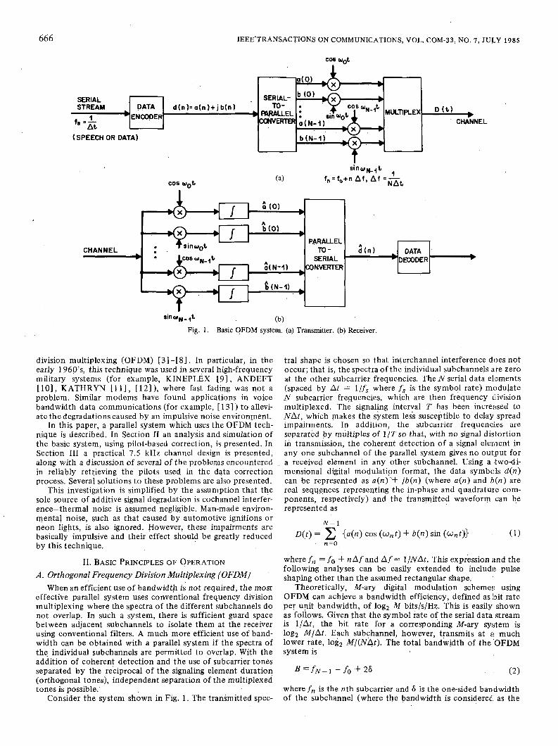
Consider the system shown in Fig. 1. The transmitted spec-
tral shape is chosen so that interchannel interference does not occur; that is, the spectra of the individual subchannels are zero at the other subcarrier frequencies. The N serial data elements (spaced by At = l/f, where fs is the symbol rate) modulate N subcarrier frequencies, which are then frequency Chvision multiplexed. The signaling interval T has been increased to N A t , which makes the system less susceptible to delay spread impairments. In addition, the subcarrier frequencies are separated by multiples of 1/T so that, with no signal dislortion in transmission, the coherent detection of a signal element in any one subchannel of the parallel system gives no output for a received element in any other subchannel. Using a twodi- mensional digital modulation format, the data symbols d ( n ) can, be represented as a(n) '+ jb(n) (where a ( n ) and b ( n ) are real sequences representing the in-phase and quadratur,e com- ponents, respectively) and the transmitted waveform can be represented as
N - 1
where f n = fo + n A f and A f = 1/NAt . This expression ;tnd the following analyses can be easily extended to include pulse shaping other than the assumed rectangular shape.
Theoretically, M-ary digital modulation scheme:: using OFDM can achieve a bandwidth efficiency, defined as 'bi t rate per unit bandwidth, of logz M bits/s/Hz. This is easily shown as follows. Given that the symbol rate of the serial data stream is l /At , the bit rate for a corresponding M-ary syljtem is log2 M/At . Each subchannel, however, transmits at z ! much lower rate, log2 M/(NAt> . The total bandwidth of the 'OFDM system is
where fn is the nth subcarrier and 6 is the one-sided bandwidth of the subchannel (where the bandwidth is considerec: as the

CIMINI: ANALYSIS AND SIMULATION OF DIGITAL MOBILE CHANNEL 667
COCHANNEL INTERFERER
/STREAM\
PILOT
/ I
R (m) a ( n ) ,
hL PARALLEL PHASE GAIN FFT-,
6h1) ' *CORRECTION CORRECTION TO SERIAL . t CONVERTER
- - Fig. 2. OFDM system implemented with an FFT.
distance to the first null). The subcarriers are uniformly spaced so that f N - - fo = (N - 1)Af. Since A f = l /NAt due to the orthogonality constraint, f N - 1 - fo = (1 - ( l /N))( l /&). Therefore, the bandwidth efficiency P becomes
(3)
For orthogonal frequency spacing and strictly band-limited spectra (bandwidth Af) with 6 = 4 Af = 1/2NAt, = log2 M bits/s/Hz. In reality, however, the spectra overflow this min- imum bandwidth by some factor CY so that 6 = ( I + a ) ( l / 2NA[) and the efficienc,y (3) becomes
p=- log' < log2 M. CY
1 +- N
To obtain the highest bandwidth efficiency in an OFDM sys- tem,N must be large and CY must be small.
B. Implementation of OFDM Using the Discrete Fourier Transform
The principal objections to the use of parallel systems are the complexity of the equipment required to implement the system, and the possibility of severe mutual interference among subchannels when the transmission medium distorts the sig- nal. The equipment complexity (filters, modulators, etc.) can be greatly reduced by eliminating any pulse shaping, and by using the discrete Fourier transform (DFT) t o implement the modulation processes, as shown in [71, 181 . There it is shown that a multitone data signal is effectively the Fourier trans- form of the original data stream, and that a bank of coherent demodulators is effectively an inverse Fourier transform. This can be seen by writing (1) as
n =0
Letting t = mAt, the resulting sampled sequence D ( m ) is seen as the real part of the DFT of the sequence d(n).l The act of truncating the signal t o t he interval (0, NAt) imposes a sin x/x frequency response on each subchannel with zeros at multiples of 1/T. This spectral shape has large sidelobes, and gives rise t o significant interchannel interference in the presence of multi- path. This point will be discussed in more detail in Section 111.
' It is convenient in this paper to think of d(n) as being in the frequency domain and D(m) as being in the time domain, contrary to the, usual engineering interpretation [8].
7- DECODER
Further reductions in complexity are possible by using the fast Fourier transform (FFT) algorithm to implement the DFT when N is large.
C. Pilot-Based Correction If the transmission channel is distortionless, the orthogo-
nality of the subcarriers allows the transmitted signals to be received without error at the receiver. Consider the system in Fig. 2 with the block of data represented by the sequence of N complex numbers {d(O), d( l ) , .-, d(N - 1)). These complex numbers are generated byethe data encoder from a binary data sequence. A DFT is performed on this block of data, giving the transmitted symbols2
N - 1
Notice that this is a sampled version of ( 5 ) where the complex notation has been retained. All future analyses will be done in the complex domain. Under the assumption of a distortionless channel, the received data sequence (the output of the inverse DFT) will be exactly the transmitted sequence due to the orthogonality of the subcarrier tones (exponentials).
If the transmission channel distorts the signal, this orthog- onality is impaired. In a flat Rayleigh fading environment (i.e., the environment is not frequency selective), the effects of the Rayleigh channel can be represented as a multiplicative noise process on the transmitted signal. This multiplicative process is characterized by a complex fading envelope with samples Z ( m ) = A ( m ) e l e ( m ) where the A ( m ) are samples from a Ray- leigh distribution and the B(m) are samples from a uniform distribution [ 11. These samples multiply the sequence of (6) to give
R(m) = Z(m)D(m). (7)
The output data sequence i ( k ) is the inverse DFT of (7),
N - 1
= d(n)z(k - n ) n =o
* Throughout this paper, all indexes will be assumed to belong to the set (0, 1, 2, ..., N - 1 ) .
668 IEEE TRANSACTIONS ON COMMUNICATIONS, VOL. COM-33, NO. 7, JULY 1985
where z ( n ) is the inverse DFT of Z(m) . It can be seen from (8) that there is a complex-weighted averaging of the samples of the complex fading envelope. If Z ( m ) = 1 for all m (the distortionless channtl), z (k - n ) is simply the Kronecker delta function 6 k n and d ( k ) = d(k). In the presence of fading, z ( k - n ) # 6kn and
N - 1
n=O n#k
The second term on the right represents the interchannel (in- tersymbol) interference caused by the loss of orthogonality. Without correction for the fading, the output sequence is cor- rupted by intersymbol interference even if there is no cochan- ne1 interferer.
Pilot-based correction provides an amplitude and phase reference which can be used to counteract the unwanted ef- fects of multipath propagation. Similar considerations have been analyzed for single-sideband mobile-radio systems [ 141, [ 151. Coherent detection, by definition, requires a phase reference; however, gain correction is also needed in an OFDM system in a fading environment to remove intersymbol inter- ference. If phase and gain correction is employed in the absence pf cochannel interference, it is easily shown, in (9), that d ( k ) = d(k) .
In a cellular mobile system, the dominant transmission impairment often comes from other users using the same carrier frequency. It is assumed here that the desired signal and a single undesired cochannel interferer are received si- multaneously, and that both are digital signals modulated by different data sequences with identical signaling rates. It is also assumed that they are subject to mutually independent Rayleigh fading.
When a cochannel interferer is present in the received sig- nal, it is not advantageous to do unlimited gain correction, due to the possibility of enhancing the energy of the interferer during deep fades of the desired signal. The detrimental effects of unlimited gain correction in the presence of a cochannel interferer can be seen as follows. Let D(m) be the desired transmitted signal sequence and let I ( m ) be the correspondin cochannel interferer sequence. With Zd ( m ) = A d ( m ) e j e d ( m y and Z i ( m ) = A j ( m ) e l e l ( m ) the desired and interferer com- plex fading sequences, respectively, the sequence present at the receiver can be represented as
R(m) = zd (nz>D(m> + f i z i ( W ( m > (10)
where y is the interference-to-signal power ratio (SIR-l) . R ( m ) is corrected by a complex correction sequence Zc(rn) = Z,(m), the complex pilot fading envelope, giving
Taking the inverse DFT of (1 l), the received data sequence becomes
N - l N--l 1 z j ( m )
n=o m=o N Z p ( m ) = d(n)z(k - n ) + fi X - -
i
If unlimited gain and phase correction is used [i.e., Z p ( , m ) = Z d ( m ) ] , Z(k - n ) = 6 k n , there is no intersymbol interference, and ( 12) becomes
The only distortion is caused by the cochannel inte~ferer. However,. since Zi(rn) and Z d ( m ) are statistically independent, the desired signal may be in a fade when the interferer is not, and unlimited gain correction may boost the interferer alrerage energy above that of the desired signal.
One alternative t o unlimited gain and phase correctio!l is t o have a limit on the gain correction, so as not to follow t:he de- sired signal into deep fades [ l ] . This is done at the expense of increased intersymbol interference, due to imperfect correc- tion of the desired signal. In this situation, the correction sig- nal is of the form
where E is the gain limit and is defined relative to the average value of the local field strength. Therefore, in (1 2), z (k -- n ) # 6,,, resulting in intersymbol interference. Consequently, there is a tradeoff between increasing the intersymbol interference and boosting the cochannel interference energy.
Another alternative is to develop an optimum gain coset- tion factor which takes both distortion effects into account. An optimum gain correction factor F ( m ) has been deri’rfd by minimizing the mean-square distortion betweenD(m) andD(m). The derivation of F ( m ) has been omitted for the sake of brevity. The correction sequence then becomes
Zc(m = z, (m )F(m)
=Z,(m) [1+ .(3)>’]. This correction procedure would be more difficult to imple- ment than the gain limiting procedure described above. ..*
In addition to the impairments caused by intersymbol and cochannel interference, frequency-selective fading may also be present. This phenomenon causes a decorrelation of :the re- ceived signal envelopes at different frequencies, lessening the effectiveness of the pilot-correction procedure, since a data point which is being corrected may be decorrelated from the corresponding pilot complex fading envelope.
Finally, one of the major advantages of the OFDM tech- nique is its ability to “average” out impairments, making ,the bursty Rayleigh channel appear much less bursty. The extent to which this averaging approaches a Gaussian channel de- pends on the correlation between samples of the complex fading envelope. It can be seen that as N increases, more inde- pendent fades are averaged. This enables burst errors to be randomized and thereby aids in bit error correctiorl. This property will be more evident in the simulation results, which indicate that the curves for the bit error rate fall betwcen the linear Rayleigh channel curves and the exponential Glmssian channel curves. For large N and high vehicle speeds, the bit error curve approaches that for a Gaussian channel.
D. Distortion Analyses Several mechanisms contribute to the overall distortion of
the desired signal. In this section, emphasis is on the contribu- tions due to gain limiting, evident in increased inter!;ymbol interference, and due to cochannel interference. The distor-
CIMINI: ANALYSIS AND SIMULATION OF DIGITAL MOBILE CHANNEL 669
tion resulting from decorrelation of the pilot due to frequency- selective fading or due to interference on the pilot is considered in Section 11-F.
First, consider the case of gain-limited correction, where the amplitude correction is bounded to follow fades only as deep as E. Assume that the random processes which produce the random sequences are ergodic, thereby permitting the equivalence of time and ensemble averages. The pilot complex fading envelope at a particular instant in time is Z,(m) = z d ( m ) and the correction sequence is
Z,(m> = max (Ad(m) , e)e ied(m). (16)
The corrected output samples become
The signal-to-distortion ratio (SDR) can be defined as in [ 141,
where x denotes a time average of X . Assuming I D(m) I z = ]l(m)' = 1 , the denominator in ( 1 8) reduces to
I b ( m ) - D(m> l 2
Assuming time averages can be replaced by expected values and assumingdd(m) andAi(m) are statistically independent and Rayleigh distributed, ( 1 8) becomes, after some manipulations,
S
+ T 1 SIR
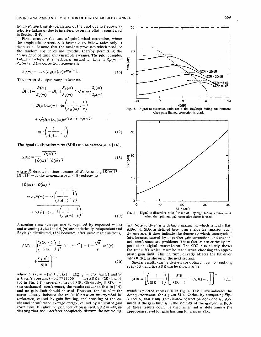
where E,(x) = -[@ + In (x) + (-l)"x"/nn!)J and \k is Euler's constant (=0.57721566 .-). The SDRin (20) is plot- ted in Fig. 3 for several values of SIR. Obviously, if SIR = - (no cochannel interference), the results reduce to that in [ 141 and no gain limit should be used. However, for SIR < 00 the curves dearly indicate the tradeoff between intersymbol in- terference, caused by gain limiting, and boosting of the co- channel interference average energy, caused by unlimited gain correction. If unlimited gain correction is used, SDR = -00, in- dicating that the interferer completely distorts the desired sig-
c !s 8 a
10 - dB
=io dB =I5 dB
I I I I I -30 -20 -10 0 10
€(dB) Fig. 3. Signal-to-distortion ratio for a flat Rayleigh fading environment
when gain-limited correction is used.
I I I
0 10 20 30 40 SIR (dB)
Fig. 4. Signal-to-distortion ratio for a flat Rayleigh fading environment when the optimum gain correction factor is used.
nal. Notice, there is a definite maximum which is fairly flat. Although SDR as defined here is an analog transmission qual- ity measure, it does indicate the degree to which intersymbol interference, caused by imperfect gain correction, and cochan- ne1 interference are problems. These factors are critically im- portant in digital transmission. The SDR also clearly shows the tradeoffs which must be made when choosing the appro- priate gain limit. This, in turn, directly affects the bit error rate (BER), as shown in the next section.
Similar results can be derived for optimum gain correction, as in (IS), and the SDR can be shown to be
SDR = [( &) [ & In (SIR) - 1 I]-' (21)
which is plotted versus SIR in Fig. 4. This curve indicates the best performance for a given SIR. Notice, by comparing Figs. 3 and 4, that using gain-limited correction does not sacrifice much if the gain limit is in the vicinity of the maximum. Both of these results could be used as an aid in determining the appropriate level for gain limiting for a given SIR.

670 IEEE TRANSACTIONS ON COMMUNICATIONS, VOL. COM-33, NO. 7 , JULr‘ 1985
E. Simulation Results Initial simulations were performed assuming flat Rayleigh
fading. In these simulations, it was also assumed that the pilots could be recovered perfectly; that is, there is no inter- ference or distortion on the pilots. A symbol rate and chan- nel bandwidth of 7.5 kHz3 were used and the BER was deter- mined for several values of SIR (100 000 bits were used in the simulation to provide statistical significance). Based on this choice for the bandwidth, the maximum bit rate is 7.5 log2 M kbits/s. Several parameters were vaned in this initial investiga- tion, the most important being N , the number of subchannels, and u, the vehicle speed. Both quantities are very important factors in determining the ability of this system to effectively randomize the burst errors created by the Rayleigh fading. The fading rate is directly proportional to the vehicle speed. In particular, at a carrier frequency of 850 MHz, independent fades are about 7 in apart, giving a fade every 6.6 ms at 60 mph. Therefore, for a given value of N , higher vehicle speeds should result in better performance because more fades are included in the averaging process. Similarly, for a given ve- hicle speed, if N is large, the total signaling interval is also large and more fades are again used in the averaging process.
The results shown in Fig. 5 , where quadrature phase shift keying (QPSK) has been employed, indicate the improvement possible if OFDM is used with gain correction under the as- sumptions of ideal pilot recovery and a flat Rayleigh fading environment. Results for both optimum gain correction, as in (1 5), and gain-limited correction, as in (14), are given. These results clearly indicate the effects of vehicle speed and the number of subchannels. At a carrier frequency of 850 MHz and with a vehicle speed of 60 mph, with gain-limited correc- tion, improvements in SIR of 6-7 dB4 have been obtained using 5 12 subchannels ( T = 6 8 ms). This is in comparison to a flat Rayleigh channel using coherent detection ( N = 1) with QPSK. A reduction in speed t o 30 mph results in a loss in performance of less than 1 dB. A reduction of N to 128 sub- channels-(T = 17 ms) results in an additional 2 dB loss, be- cause fewer independent fades are included in the averaging process. For the cases where gain-limited correction is used, the BER curves shown are for the “best” absolute gain limit. If the optimum gain correction factor can be determined, an additional improvement of 1 dB can be obtained. The sensi- tivity of the BER on the gain limit, shown in Fig. 6, indicates that adaptive gain limiting, or some “intelligent” guess at the gain limit based on the distortion curves, may be required.
F. Effects of Frequency-Selective Fading When good correlation exists between the fading statistics
of the pilot tone and those of the fading information signal, almo‘st total suppression of the unwanted amplitude and phase fluctuations is possible. The simulation results given in Section 11-E were obtained under the assumption that the fading on the pilot and the desired signal were totally correlated. This is a valid consideration when there is no interference on the pilot and when the fading is not frequency selective.
In general, however, the mobile environment is frequency selective, due to the existence of a spread in arrival times of the various multipath components. In this case, the correlation in phase and amplitude between two pilots separated in fre- quency is high for small frequency separation, and falls essen- tially to zero as the separation substantially exceeds the correla- tion bandwidth [ 1 ] . The gain correction process, as will be seen, requires a high degree of correlation between the phase and
Such a channel allows a factor of 4 improvement in spectral efficiency
All comparisons in this paper will be made at a BER level of over the current 30 kHz cellular mobile telephone service channel.
10 0
lo-’
40-2
E W m
10-3
I 0-4
10-5
1 1 1 1 1 1 1 1 1 1 1 1
- N= 512 v.60 MPH, OPTIMUM GAIN CORRECTION --- N= 512, v 560 MPH, GAIN-LIM~TED CORRECTION
***.. N.512,~ =30 MPH, GAIN-LIMITED CORRECTIIW .-e- N.128, v = ~ O MPH, GAIN-LIMITED CORRECTION
0 2 4 6 8 10 12 44 16 18 2 0 22 24 26
SIR (dB) Fig. 5 . Simulation results assuming perfect pilot recovery in a flat kayleigh
fading environment (QPSK, = 7.5 Hz).
I 10’~
I d4
- S I R = I b d B
SIR
/ /
1 6 ~ 6 I -24 -22 -20-18 -16 -14-12 -10 -0 -6 - 4 - 2
Fig. 6. Sensitivity of BER to variations in gain limit (N = 512, u = 60 mph,f, = 7.5 kHz).
CIMINI: ANALYSIS AND SIMULATION OF DIGITAL MOBILE CHANNEL 67 1
amplitude variations of the pilot and that of the phase and amplitude variations imposed on the data.
A simple'way to estimate the effects of a delay spread en- vironment is to compute the equivalent decorrelation between the pilot and the data caused by the frequency-selective fading (for example, see [ 121). These calculations depend on the model used t o describe the dispersive channel. In the simula- tions, the delay spread channel is simply modeled as a two-im- pulse channel response with equal-amplitude signal and echo separated by some time A. As in [2, sect. 9.81 , an approxima- tion model will be assumed for the delay distribution. In this model, the probability density function of the delay is repre- sented as two equal-amplitude, equally likely impulses sepq- rated by some delay A. This is the model which was employed in the simulation and is a sufficient approximation for s < n/2. The rms delay spread in this case is simply A/2. The corre- sponding complex correlation coefficient can be shown to be
where s is the frequency separation in rad/s, T is the separation in time between two samples, and wm is the maximum Dop- pler shift in rad/s. Letting T = 0 (without loss of generality)
1 p(s, a) = - [l + cos (sa)] 1 / 2
&- The coherence bandwidth, defined as the frequency separation when the envelope correlation ( p 2 ) is 0.5, is easily computed to be l /A. According to published data for New York City [ 161, the rms delay spread is usually less than 3 ps (A = 6 ps). However, other measurements in Newark [ 171 suggest that values of A as high as 5 0 ps are possible. Values of A = 25 p s were found to occur often enough and with sufficient repeat- ability in Newark to be regarded seriously. The usefulness of the OFDM technique has been illustrated for a flat Rayleigh fading environment. It remains to show how much the system degrades in a delay spread environment where the pilots and the data become decorrelated.
In the simulation, a bound on the effects of delay spread has been obtained by appropriately decorrelating the pilot fading sequence and the fading data sequence. At a specific instant in time, the correlation hetween the complex fading envelope of the pilot, Z,(rn), and the complex fading envelope of the data, Z,(m), is some value p < 1. It is easily shown that this will be true if the pilot complex fading envelope is chosen as
where Zx(rn) is statistically independent from Zd(m) . In the previous section, p was assumed to'be unity. Obviously, this process causes additional distortion. Using limited gain correc- tion, it can be shown that in a frequency-selective environment the SDR is
P+ cos @ - erf ( E ) + 1 - p2 + - E 1 ( e 2 ) E ( S:R) I-'
(25)
where @ = arctan [-sa]. This reduces to (20) for p = 1 and reduces to results in [ 141 when SIR = m and @ = 0.
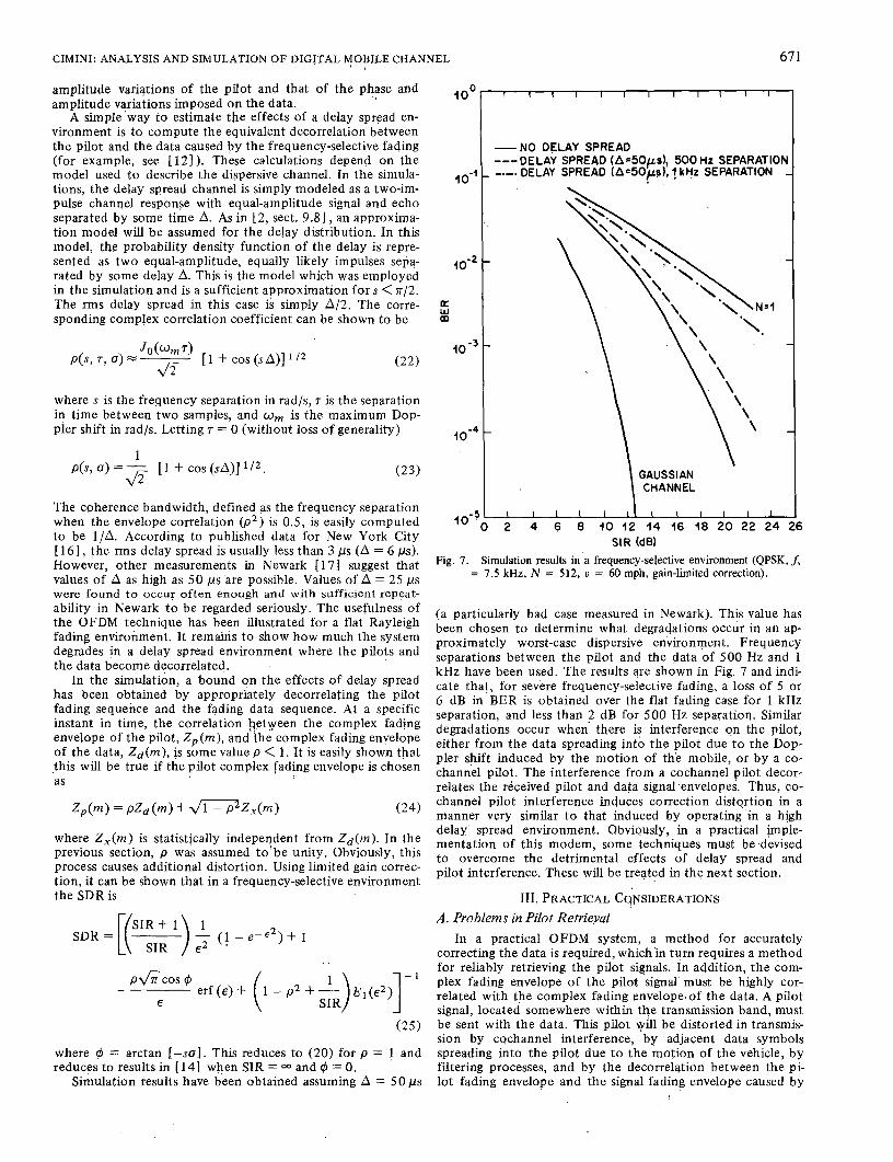
Simulation results have been obtained assuming A = 5 0 ps
loo r -NO DELAY SPREAD ---DELAY SPREAD (A'5OpdI 500 HZ SEPARATIOI
,o-~ -.-. DELAY SPREAD ( A e 5 0 p ) , j kHz SEPARATION
io-2
a m w
lom3
IO-^ \
GAUSSIAN CHANNEL
6 SIR (dB)
Fig. 7. Simulation results in a frequency-selective environment (QPSK, f, = 7.5 kHz, N = 512, u = 60 mph, gain-limited correction).
(a particularly bad case measured in Newark). This value has been chosen to determine what degradations occur in an ap- proximately worst-case dispersive environment. Frequency separations between the pilot and the data of 500 Hz and 1 kHz have been used. The results are shown in Fig. 7 and indi- cate that, for severe frequency-selective fading, a loss of 5 or 6 dB in BER is obtained over the flat fading case for 1 kHz separation, and less than 2 dB for 500 Hz separation. Similar degradations occur when there is interference on the pilot, either from the data spreading into the pilot due to the Dop- pler shift induced by the motion of the mobile, or by a co- channel pilot. The interference from a cochannel pilot decor- relates the received pilot and data signal -envelopes. Thus, co- channel pilot interference induces correction distortion in a manner very similar to that induced by operating in a high delay' spread environment. Obviqusly, in a practical jmple- mentation of this modem, some techniques must be devised to overcome the detrimental effects of delay spread and pilot interference. These will be treated in the next section.
III. PRACTICAL C~NSIDERATIONS . .
A . Problems in Pilot Retrieval In a practical OFDM system, a method for accurately
correcting the data is required, whichin turn requires a method for reliably retrieving the pilot signals. In addition, the com- plex fading envelope of the pilot signal' must be highly cor- related with the complex fading envelope,of the data. A pilot signal, located somewhere within the transmission band, must be sent with the'data. This pilot will be distorted in transmis- sion by cochannel interference, by adjacent data symbols spreading into the pilot due to the motion of the vehicle, b y filtering processes, and by the decorrelqtion between the pi- lot fading envelope and the signal fading envelope caused by
672 IEEE TRANSACTIONS ON COMMUNICATIONS, VOL. COM-33, NO. 7 , JULY 1985
a frequency-selective environment. Techniques will be pre- sented which alleviate these distortions.
B. Techniques for Reliable Pilot Retrieval When there is adequate separation between the pilot tone
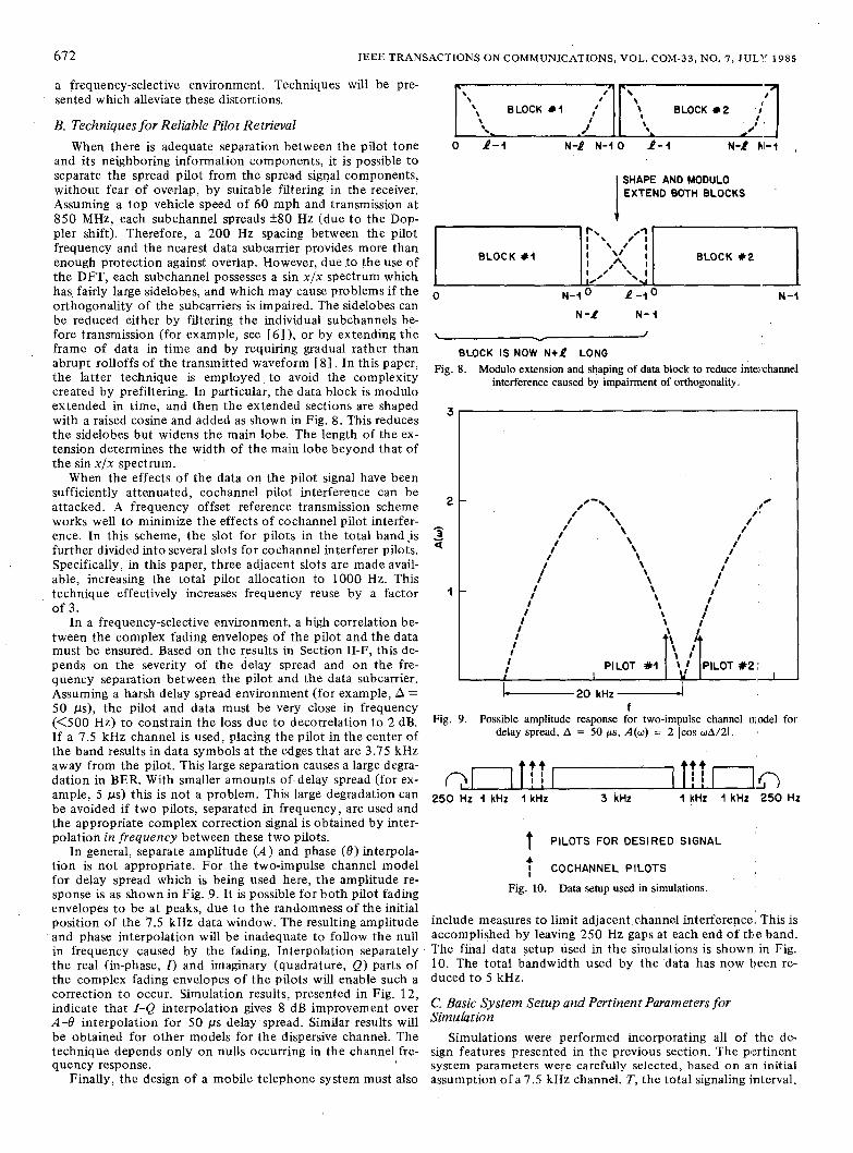
and its neighboring information components, it is possible to separate the spread pilot from the spread signal components, without fear of overlap, by suitable filtering in the receiver. Assuming a top vehicle speed of 60 mph and transmission at 850 MHz, each subchannel spreads +80 Hz (due to the Dop- pler shift). Therefore, a 200 Hz spacing between the pilot frequency and the nearest data subcarrier provides more than enough protection against overlap. However, due to the use of the DFT, each subchannel possesses a sin xfx spectrum which has. fairly large sidelobes, and which may cause problems if the orthogonality of the subcarriers is impaired. The sidelobes can be reduced either by filtering the individual subchannels be- fore transmission (for example, see [ 6 ] ) , or by extending the frame of data in time and by requiring gradual rather than abrupt rolloffs of the transmitted waveform [ 81. In this paper, the latter technique is employed, to avoid the complexity created by prefiltering. In particular, the data block is modulo extended in time, and then the extended sections are shaped with a raised cosine and added as shown in Fig. 8. This reduces the sidelobes but widens the main lobe. The length of the ex- tension determines the width of the main lobe beyond that of the sin x/x spectrum.
When the effects of the data on the pilot signal have been sufficiently attenuated, cochannel pilot interference can be attacked. A frequency offset reference transmission scheme works well to minimize the effects of cochannel pilot interfer- ence. In this scheme, the slot for pilots in the total bandis further divided into several slots for cochannel interferer pilots. Specifically, in this paper, three adjacent slots are made avail- able, increasing the total pilot allocation to 1000 Hz. This technique effectively increases frequency reuse by a factor of 3.
In a frequency-selective environment, a high correlation be- tween the complex fading envelopes of the pilot and the data must be ensured. Based on the results in Section 11-F, this de- pends on the severity of the delay spread and on the fre- quency separation between the pilot and the data subcarrier. Assuming a harsh delay spread environment (for example, A = 50 ps), the pilot and data must be very close in frequency (<500 Hz) to constrain the loss due to decorrelation to 2 dB. If a 7.5 kHz channel is used, placing the pilot in the center of the band results in data symbols at the edges that are 3.75 kHz away from the pilot. This large separation causes a large degra- dation in BER. With smaller amounts of-delay spread (for ex- ample, 5 ps) this is not a problem. This large degradation can be avoided if two pilots, separated in frequency, are used and the appropriate complex correction signal is obtained by inter- polation in frequency between these two pilots.
In general, separate amplitude ( A ) a d phase ( 8 ) interpola- tion is not appropriate. For the two-impulse channel model for delay spread which is being used here, the amplitude re- sponse is as shown in Fig. 9. It is possible f0.r both pilot fading envelopes to be at peaks, due to the randomness of the initial position of the 7.5 kHz data window. The resulting amplitude and phase interpolation will be inadequate to follow the null in frequency caused by the fading. Interpolation separately the real (in-phase, I ) and imaginary (quadrature, Q ) parts of the complex fading envelopes of the pilots will enable such a correction to occur. Simulation results, presented in Fig. 12, indicate that I-Q interpolation gives 8 dB improvement over A-8 interpolation for 50 ps delay spread. Similar results will be obtained for other models for the dispersive channel. The technique depends only on nulls occurring in the channel fre- quency response.
Finally, the design of a mobile telephone system must also
n I m\
\
\\ BLOCK # I ,‘ 1 BLOCK # 2 .g I \ I
I \
8. ~
0 1 - 1 N-& N - I O 1 - 1 N-P bl-1 , ‘8. 20’
I SHAPE AND MODULO EXTEND BOTH BLOCKS
p\ 89 -
I 8 / I
BLOCK # I ‘,I‘
I .2 I I ,’ \\ I
BLOCK # 2
0 I/ 4 7 N - l o 1 - l o N -1
N -1 N- I
\ J v
BLOCK IS NOW N+k? LONG Fig. 8. Modulo extension and shaping of data block to reduce interchannel
interference caused by impairment of orthogonality.
3
2
0
3 9 -
1
j ! @
/ /
I I
I I
I
i
I I
i
/ PILOT 9 2 ;
7 c 2 0 kHz f
Fig. 9. Possible amplitude response for two-impulse channel ni,odel for delay spread, A = 50 ps, A(w) = 2 lcos wA/2( .
I yrt I I I I I?? I I [ 250 Hz I kHz 1 kHz 3 kHz I kHz 1 kHz 250 Hz
1 PILOTS FOR DESIRED SIGNAL
4 COCHANNEL PILOTS
Fig. 10. Data setup used in simulations.
include measures to limit adjacent.channe1 interference. This is accomplished by leaving 250 Hz gaps at each end of th.e band. The final data setup used in the simulations is shown, in Fig. 10. The total bandwidth used by the data has now been re- duced to 5 kHz.
C. Basic System Setup and Pertinent Parameters for Sirnuletion
Simulations were performed incorporating all of :the de- sign features presented in the previous section. The pertinent system parameters were carefully selected, based on a:n initial assumption of a 7.5 kHz channel. T , the total signaling interval,

CIMINI: ANALYSIS AND SIMULATION OF DIGITAL MOBILE CHANNEL 673
4-ARY (Q PS K) dmin = 4.41
(7PSK- 01 8 - A R Y
16-ARY (QA M 1 ___+____ dmin = 0.63
x x x x x x
Fig. 1 1 . Modulation formats used in simulations (average energy = 1).
should be chosen to be much greater than the average dura- tion between fades, so that many fades are averaged in the receiver. In the previous simulation, T was 68 ms and good results were obtained. However, based on subjective opinions, a signaling interval of 68 ms was shown to result in a notice- able round trip delay for speech transmission when buffer- ing and processing times are included. Also, by making T too large, the subchannels are closer together and the inter- channel interference due to spreading may become unaccept- able. An interval on the order of 20 ms (N = 128) is more satisfactory. This decrease in T results in a degradation of about 2 dB in performance compared t o T = 68 ms.
Note that the average interval between fades tends to in- finity as the speed of the mobile approaches zero. Therefore, T must be very large at low speeds to obtain any averaging. A solution to this problem is to make the vehicles always ap- pear to move at some substantial speed, such as 30 mph. One way this can be done is by forcing an antenna to oscillate when the vehicle is moving at low speeds, as in [ 181.
Assuming an initial sample rate of 7.5 kHz and letting N = 128 gives T = 17.06 ms and A f = 58.59 Hz. Assuming a total interval of 20 ms, these parameters allow 2.93 ms of extension. Sacrificing two bands of 1000 Hz each for pilot protection and 250 HZ at either end for adjacent channel interference protec- tion leaves space for 86 data channels and a bandwidth ef- ficiency of 0 = 0.57 log2 M bits/s/Hz. For QPSK, this corre- sponds to a maximum data rate o f 8.6 kbits/s.
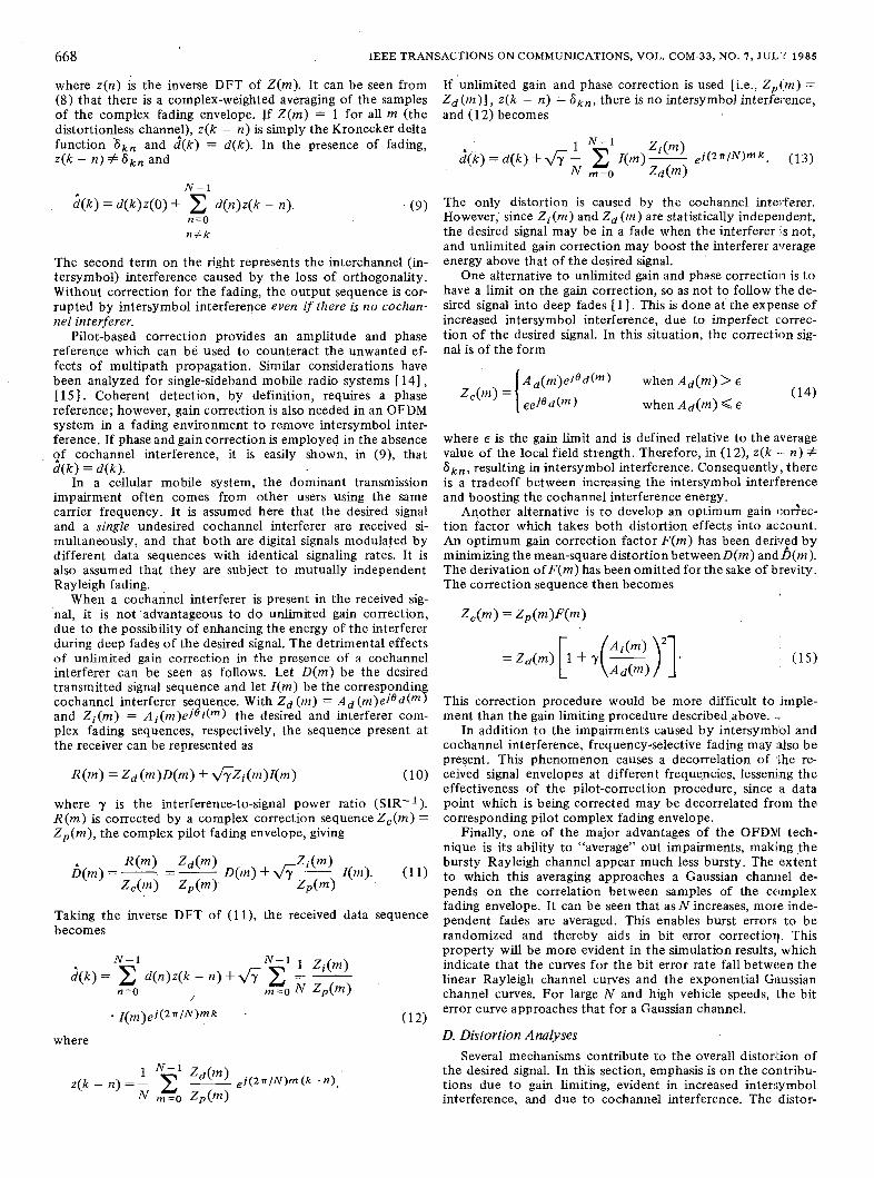
D. Simulation Results In this simulation, several different two-dimensional modu-
lation formats were considered. These are shown in Fig. 11, along with the corresponding minimum distances. Results
I O 0
( - - I 2
I o-2
E W m
1 o - ~
1 o - ~
I o - ~
DELAY SPREAD,A =50 p ~ , 4-ARY8 A-8 ...... .. N = l , NO DELAY SPREAD ._._._DELAY SPREAD, h=50~8. 4-ARY. 1-0
2 4 6 8 I O 12 14 16 18 20 22 24 S I R (dB)
Fig. 12. Simulation results (N = 128, u = 30 mph,f, = 7.5 kHz).
were obtained for binary (BPSK), 4-ary (QPSK), 8-ary (7PSK-0), and 16-ary (QAM) modulation schemes. The 8-ary constellation used a seven-point phase shift keying pattern with an additional data point at the origin. This requires a two- step detection procedure, but gives 1.7 dB improvement in performance over conventional 8-PSK, based on comparison of the minimum distances in each constellation. These pat- terns could form the basis of a multimode system.
Simulation results for a flat Rayleigh fading environment are shown in Fig. 12. Gain-limited correction has been used in the data correction process. These results are computed for a vehicle speed of 30 mph. For a. vehicle speed of 60 mph, there is an improvement of 1 dB. Each pilot was also run 10 dB higher in energy than any individual data point, for ad- ditional protection of the pilots. By using the frequency off- set reference technique to combat cochannel pilot interfer- ence, the total pilot-to-distortion ratio is 25 dB, a reasonable level of distortion. The pilot filters were implemented, in the simulation, as low-pass FIR filters with 100 Hz passbands. These filters added no significant distortion to the pilots. The results in Fig. 12 indicate the improvements which are attain- able with this technique. Gains of 2-3 dB were obtained for OFDM-QPSK over coherent QPSK. An additional 3 dB is gained over differential QPSK (DQPSK).
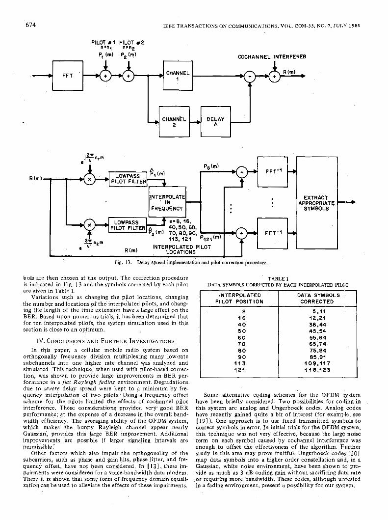
Fig. 12 also indicates the BER for QPSK when there is sig- nificant delay spread. Delay spread was implemented as a sta- tistically independent delayed echo added to the desired sig- nal. At a BER = lop2 , there is a loss of only 2 dB in SIR for A = 50 ps. For A = 10 ps, the loss is about 0.5 dB. The losses due to delay spread have been minimized by interpolating in frequency ten appropriately spaced pilots, which are then each used to correct the data sequence. The appropriate sym-
674 IEEE TRANSACTIONS ON COMMUNICATIONS, VOL. COM-33, NO. 7, JULY 1985
R (m)
PILOT # I PILOT #2 n=n4 n=n2
T COCHANNEL INTERFERER
--., CHANNEL 1
CHANNEL DELAY
'?, (m) + INTERPOLATE
FREQUENCY ' IN
. . .
t n=6,16, fiz (m). 70, 80,90,
40,50,60,
113,121 P12?(m)
LOCATIONS - INTERPOLATED PILOT
1 Fig. 13. Delay spread implementation and pilot correction procedure.
. .
TABLE I bols are then chosen at the output. The correction procedure is indicated in Fig. 13 and the symbols corrected by each pilot are given in Table'I.
Variations suFh as changing the pilot locations, changing the number and locations of the interpolated pilots, and chang- ing the length of the time extension have a large effect on the BER. Based upop numerous trials, it has been determined that for ten interpolated pilot's, the system simulation used in this section is close to an optimum.
IV. CONCLUSIONS AND FURTHER INVESTIGATIONS In this paper, a cellular mobile radio system based on
orthogonally frequency division multiplexing many low-rate subchannels into one higher rate channel was analyzed and simulated. This technique, when used with pilot-based correc- tion, was shown to provide large improvements in BER per- formance in a f l a t Rayleigh fading environment. Degradations due to severe delay spread were kept to a minimum by fre- quency interpolation of two pilots: Using a frequency offset scheme for the pilots limited the effects of cochannel pilot interference. These considerations provided very' good BER performance; at the expense of a decrease in the overall band- width efficiency. The averaging ability of the OFDM system, which makes' the bursty Rayleigh channel appear nearly Gaussian, provides this large BER improvement. Additional improvements are possible if larger signaling intervals are permissible:'
Other factors which also impair the orthogonality of the subcarriers, such as phase and gain hits, phase jitter, and fre- quency offset, have not been considered. In [ 131, these im- pairments were considered for a voice-bandwidth data modem. There it is shown that some form of frequency domain equali- zation can be used to alleviate the effects of these impairments.
EXTRACT 4PPROPRIATE
SYMBOLS
DATA SYMBOLS CORRECTED BY EACH INTERPOLATED PILC~T
INTERPOLATED PILOT POSITION
8 16 40 50 60 70 80 90
113 121
DATA SYMBO.LS CORRECTED
38.44 45,54 55.64 65.74 75,84 85,91
109.11 7 I 18,123
Some alternative coding schemes for the OFDM ;;ystem have been briefly considered. Two possibilities for coding in this system are analog and Ungerboeck codes. Analog codes have recently gained quite a bit of interest (for example, see [ 191). One approach is t o use fixed transmitted symbols to correct symbols in error. In initial trials for the OFDM system, this technique was not very effective, because the largl: noise term on each symbol caused by cochannel interference was enough to offset the effectiveness of the algorithm. Further study in this area may prove fruitful. Ungerboeck codf's [ 2 0 ] map data symbols into a higher order constellation and, in a Gaussian, white noise environment, have been shown'to pro- vide as much as 3 dB. coding gain without sacrificing data rate or requiring more bandwidth. These codes, although untested in a fading environment, present a possibility for our system.

CIMINI: ANALYSIS AND SIMULATION OF DIGITAL MOBILE CHANNEL 675
ACKNOWLEDGMENT The author would like to acknowledge gratefully N. Sollen-
berger and K. Leland for their helpful suggestions throughout the course of this project.
[71
REFERENCES
W. C. Jakes, Jr. , Ed., Microwave Mobile Communications. New York: Wiley, 1974. W. C. Y. Lee, Mobile Communications Engineering. New York: McGraw-Hill, 1982. R. W. Chang, “Synthesis of band-limited orthogonal signals for multichannel data transmission,” Bell Syst. Tech. J. , vol. 45, pp. 1775-1796, Dec. 1966.
3 488 445, tiled Nov. 14, 1966, issued Jan. 6, 1970. B. R. Saltzberg, “Performance of an efficient data transmission system,” IEEE Trans. Commun. Technol., vol. COM-15, pp. 805- 813, Dec. 1967. R. W. Chang and R. A. Gibbey, “A theoretical study of performance of an orthogonal multiplexing data transmission scheme,” ZEEE Trans. Commun. Technol., vol. COM-16, pp. 529-540, Aug. 1968. J. Salz and S. B. Weinstein, “Fourier transform communication system,” in Proc. ACM Symp. Probl. Optimiz. Data Commun. Syst., Pine Mountain, GA, October 13-16, 1969, pp. 99-128. S. B. Weinstein and P. M. Ebert, “Data transmission by frequency- division multiplexing using the discrete Fourier transform,” IEEE Trans. Commun. Technol., vol. COM-19, pp. 628-634, Oct. 1971. M. L. Doelz. E. T. Heald, and D. L. Martin, “Binary data transmission techniques for linear systems,” Proc. IRE, vol. 45, pp. 656-661, May 1957. G. C. Porter, “Error distribution and diversity performance of a frequency-differential PSK HF modem,” IEEE Trans. Commun. Technol., vol. COM-16, pp. 567-575, Aug. 1968. M. S. Zimmerman and A. L. Kirsch, “The AN/GSC-IO (KATHRYN) variable rate data modem for HF radio,” IEEE Trans. Comrzun. Technol., vol. COM-15, pp. 197-205, Apr. 1967. P. A. Bello, “Selective fading limitations of the Kathryn modem and some system design considerations,” IEEE Trans. Commun. Tech- nol., vol. COM-13, pp. 320-333, Sept. 1965. W. E. Keasler, Jr., “Reliabile data communications over the voice bandwidth telephone channel using orthogonal frequency division
- , “Orthogonal frequency division multiplexing,” U.S. Patent
multiplexing,” Ph.D. dissertation, Univ. Illinois, Urbana-Champaign, 1982.
[14] K. W. Leland and N. R. Sollenberger, “Impairment mechanisms for SSB mobile communications at UHF with pilot-based Doppledfading correction,” Bell Syst. Tech. J., vol. 59, pp. 1923-1942, Dec. 1980.
[I51 J . P. McGeehan and A. J. Bateman, “Theoretical and experimental investigation of feedforward signal regeneration as a means of combating multipath propagation effects in pilot-based SSB mobile radio systems,” IEEE Trans. Veh. Technol., vol. VT-32, pp. 106- 120, Feb. 1983.
[16] D. C. Cox and R. P. Leck, “Distributions of multipath delay spread and average excess delay for 910 MHz urban mobile radio path,” IEEE Trans. Antennas Propagat., vol. AP-23, pp. 206-213, Mar. 1975.
[17] K. W. Leland and N. R. Sollenberger, private communication. [18] W. C. Wong, R. Steele, B. Glance, and D. Horn, “Time diversity with
adaptive error detection to combat Rayleigh fading in digital mobile
‘1983. radio,” IEEE Trans. Commun., vol. COM-31, pp. 378-387, Mar.
[19] J. K. Wolf, “Redundancy, the discrete Fourier transform, and impulse noise cancellation,’’ IEEE Trans. Commun., vol. COM-31, pp. 458- 461, Mar. 1983.
[20] G. Ungerboeck, “Channel coding with multilevel/phase signals,” IEEE Trans. Inform. Theory, vol. IT-28, pp. 55-67, Jan. 1982.
* Leonard J. Cimini, Jr. (S’77-M’82) was born in Philadelphia, PA, on April 19, 1956. He received the B.S.E., M.S.E., and Ph.D. degrees in electrical engineering from the University of Pennsylvania, Philadelphia, in 1978, 1979, and 1982, respec- tively. During his graduate work he was supported by a National Science Foundation Fellowship.
He has been employed by AT&T Bell Laborato- ries, Holmdel, NJ, since 1982, working in the area
, , of mobile radio systems. His main research interests are in the general areas of signal processing and
communications systems. He also teaches courses in communication systems at Monmouth College, West Long Branch, NJ.
Dr. Cimini is a member of Tau Beta Pi and Eta Kappa Nu.