Embed Size (px)
Citation preview
978-1-5090-2364-6/17/$31.00 ©2017 IEEE
A Proposal of Consequent-Pole Type Bearingless Vernier Motor
Abstract- This paper presents a consequent pole type bearingless vernier motor which can generate high torque at low rotational speed without mechanical contacts. The conventional bearingless motor is suitable for rotating at high speed. However it is not suitable for generating high torque. Vernier motor have a particular structure. Because of that, it gets the high torque at low speed without gears. Thus, to combine bearingless motor with consequent pole type vernier motor, the proposed motor can generate high torque at low speed without any mechanical contacts. In this paper, the torque equation and the suspension force equation is shown. In addition to that, the theory and the analysis results are compared.
I. INTRODUCTION
Recently, there is a problems that is fretting or early wearing caused by reciprocating action of motors used in industrial robot arm [1]. Moreover, mechanical gears are installed in motor for generating high torque in this field. Thus, the motors
cannot use as an application that need high-cleanness environments because of the problems such as metal powder occurred by abrasion and lubrication oil caused by mechanical contacts. To resolve this problem caused by mechanical contacts, bearinglesss motor is effective because it has no mechanical contact by magnetic levitation [2]. However, bearingless motor is not suited for high torque application since mechanical gears cannot used. Therefore, we propose the consequent-pole type bearingless vernier motor (CP-VBelM). Applying technique of magnetic levitation on vernier motors, the CP-VBelM can generates high-torque without mechanical contacts because of magnetically deceleration effect by its structure. This feature lead to use the motors as robot arms that used in high-vacuum and/or high-cleanness environments that are difficult to use mechanical bearings and gears. In this paper, we proposed the CP-VBelM and explain the torque equation and the suspension force equation. Moreover, the theory and the analysis results are compared.
II. THE STRACTURE OF CP-VBELM
Fig. 1 shows sectional view of the simplified schematic of outer rotor type CP-VBelM. The rotor has consequent pole structure that the permanent magnets are inserted into between rotor teeth. The all permanent magnets are magnetized to inward radial direction and all gap surfaces are the N-pole [3].
The reason why we choose consequent-pole type is for getting the suspension force efficiently. To generate suspension force, the interference of the two kind of fluxes which means the excitation flux by the permanent magnets and the magnetic flux by the suspension winding are used. Thus, to get the space which they pass through is significant. The permeability of a permanent magnet is same as of an air and
Fig. 1. The structure of CP-VBelM
TABLE I THE SYMBOL AND ITS MEANING
Symbol Meaning
Z s The number of stator teeth
Z r The number of rotor teeth
p The pole pair number of motor winding
p s The pole pair number of suspension winding
θ r The angle of rotor coordinate
θ s The angle of stator coordinate
φ r The rotor slot pitch
ω The angular velocity of three phase alternating currentω m The rotor mechanical angular velocity
w r The width of rotor teeth
w s The width of stator teeth
N m The motor winding turns per slot
N s The motor winding turns per slot
r The radius of the air gap
μ 0 The permeability of vacuum
ξφ rThe mecahnical angle between
the stator coordinate origin and the rotor cordinate origin
k m,order The winding factor of motor winding toward the harmonics
k s,order The winding factor of suspension winding toward the harmonics
I m The rms value of the motor current
I s The DC value of suspension current
L The stack length of iron laminationτ The mechanical pole pitch length
n Positive integer numbers or zeroα, γ, l, j The integer numbers
Takahiro Sekine Tokyo City University [email protected]
Kanako Minami Tokyo City University [email protected]
Kimio Hijikata Tokyo City University
Yasuhiro Tanaka Tokyo City University
IEEE PEDS 2017, Honolulu, USA12 – 15 December 2017
373
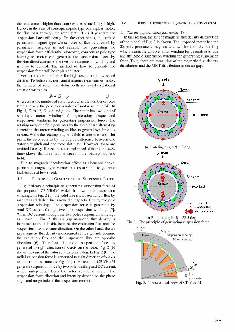
the reluctance is higher than a core whose permeability is high. Hence, in the case of consequent-pole type bearingless motor, the flux pass through the rotor teeth. Thus it generate the suspension force efficiently. On the other hands, the surface permanent magnet type whose rotor surface is covered by permanent magnets is not suitable for generating the suspension force efficiently. Moreover, consequent pole type bearingless motor can generate the suspension force by flowing direct current to the two-pole suspension winding and is easy to control. The method of how to generate the suspension force will be explained later.
Vernier motor is suitable for high torque and low speed driving. To behave as permanent magnet type vernier motor, the number of rotor and stator teeth are satisfy relational equation written as
Zs = Zr ± p (1) where ZS is the number of stator teeth, Zr is the number of rotor teeth and p is the pole pair number of motor winding [4]. In Fig. 1, ZS is 12, Zr is 8 and p is 4. The stator has two kind of windings, motor windings for generating torque and suspension windings for generating suspension force. The rotating magnetic field generates by the three phase alternating current in the motor winding as like as general synchronous motors. While the rotating magnetic field rotates one stator slot pitch, the rotor rotates by the degree difference between one stator slot pitch and one rotor slot pitch. However, these are omitted for easy. Hence, the rotational speed of the rotor is p/ZR times slower than the rotational speed of the rotating magnetic field.
Due to magnetic deceleration effect as discussed above, permanent magnet type vernier motors are able to generate high-torque at low speed.
III. PRINCIPLE OF GENERATING THE SUSPENSION FORCE
Fig. 2 shows a principle of generating suspension force of the proposed CP-VBelM which has two pole suspension windings. In Fig. 2 (a), the solid line shows excitation flux by magnets and dashed line shows the magnetic flux by two pole suspension windings. The suspension force is generated by send DC current through two pole suspension windings [5]. When DC current through the two poles suspension windings as shown in Fig. 2, the air gap magnetic flux density is increased at the left side because the excitation flux and the suspension flux are same direction. On the other hand, the air gap magnetic flux density is decreased at the right side because the excitation flux and the suspension flux are opposite direction [6]. Therefore, the radial suspension force is generated to right direction of x-axis on the rotor. Fig. 2 (b) shows the case of the rotor rotates to 22.5 deg. In Fig. 2 (b), the radial suspension force is generated to right direction of x-axis on the rotor as same as Fig. 2 (a). Hence, the CP-VBelM generate suspension force by two pole winding and DC current, which independent from the rotor rotational angle. The suspension force direction and intensity depend on the phase angle and magnitude of the suspension current.
IV. DERIVE THEORETICAL EQUATIONS OF CP-VBELM
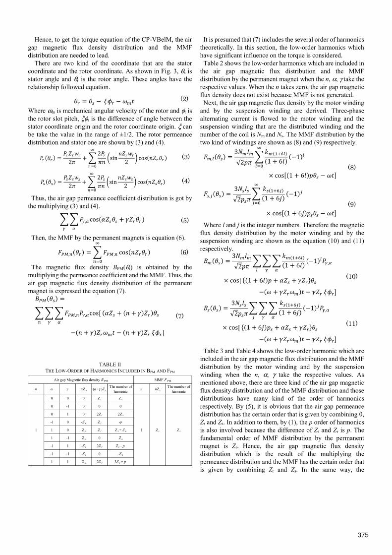
A. The air gap magnetic flux density [7] In this section, the air gap magnetic flux density distribution
of the model of Fig. 3 is shown. The proposed motor has the 2Zr-pole permanent magnets and two kind of the winding which means the 2p-pole motor winding for generating torque and the 2-pole suspension winding for generating suspension force. Thus, there are three kind of the magnetic flux density distribution and the MMF distribution in the air gap.
(a) Rotating angle θr = 0 deg
(b) Rotating angle θr = 22.5 deg Fig. 2. The principle of generating suspension force
Fig. 3. The sectional view of CP-VBelM
y-axis
x-axis
Rotor
Stator
MagnetSuspension winding
Motor winding
θr
θs
ξφr
ωt
374
Hence, to get the torque equation of the CP-VBelM, the air gap magnetic flux density distribution and the MMF distribution are needed to lead.
There are two kind of the coordinate that are the stator coordinate and the rotor coordinate. As shown in Fig. 3, θs is stator angle and θr is the rotor angle. These angles have the relationship followed equation. = − − (2) Where ωm is mechanical angular velocity of the rotor and φr is the rotor slot pitch, ξφr is the difference of angle between the stator coordinate origin and the rotor coordinate origin. ξ can be take the value in the range of ±1/2. The rotor permeance distribution and stator one are shown by (3) and (4). = 2 + 2 sin 2 cos∞
=0 (3)
= 2 + 2 sin 2 cos∞=0 (4)
Thus, the air gap permeance coefficient distribution is got by the multiplying (3) and (4).
, cos + (5)
Then, the MMF by the permanent magnets is equation (6).
, = , cos (6)
The magnetic flux density BPM(θr) is obtained by the multiplying the permeance coefficient and the MMF. Thus, the air gap magnetic flux density distribution of the permanent magnet is expressed the equation (7). =
, , cos[ + +
− + − + ] (7)
It is presumed that (7) includes the several order of harmonics theoretically. In this section, the low-order harmonics which have significant influence on the torque is considered.
Table 2 shows the low-order harmonics which are included in the air gap magnetic flux distribution and the MMF distribution by the permanent magnet when the n, α, γ take the respective values. When the n takes zero, the air gap magnetic flux density does not exist because MMF is not generated.
Next, the air gap magnetic flux density by the motor winding and by the suspension winding are derived. Three-phase alternating current is flowed to the motor winding and the suspension winding that are the distributed winding and the number of the coil is Nm and Ns. The MMF distribution by the two kind of windings are shown as (8) and (9) respectively.
, = 3√2 1 + 6 −1
× cos[ 1 + 6 − ] (8)
, = 3√2 1 + 6 −1
× cos[ 1 + 6 − ] (9)
Where l and j is the integer numbers. Therefore the magnetic flux density distribution by the motor winding and by the suspension winding are shown as the equation (10) and (11) respectively. = 3√2 1 + 6 −1 ,
× cos[ { 1 + 6 + + } − + − ] (10)
= 3√2 1 + 6 −1 ,
× cos[ { 1 + 6 + + } − + − ] (11)
Table 3 and Table 4 shows the low-order harmonic which are included in the air gap magnetic flux distribution and the MMF distribution by the motor winding and by the suspension winding when the n, α, γ take the respective values. As mentioned above, there are three kind of the air gap magnetic flux density distribution and of the MMF distribution and those distributions have many kind of the order of harmonics respectively. By (5), it is obvious that the air gap permeance distribution has the certain order that is given by combining 0, Zr and Zs. In addition to them, by (1), the p order of harmonics is also involved because the difference of Zs and Zr is p. The fundamental order of MMF distribution by the permanent magnet is Zr. Hence, the air gap magnetic flux density distribution which is the result of the multiplying the permeance distribution and the MMF has the certain order that is given by combining Zr and Zs. In the same way, the
TABLE II THE LOW-ORDER OF HARMONICS INCLUDED IN BPM AND FPM
n α γ αZ s (n +γ )Z rThe number of
harmonicn nZ r
The number ofharmonic
0 0 0 Z r Z r
0 -1 0 0 0
0 1 0 2Z r 2Z r
-1 0 -Z s Z r -p
1 0 Z s Z r Z r + Z s
1 -1 Z s 0 Z s
-1 1 -Z s 2Z r Z r - p
-1 -1 -Z s 0 -Z s
1 1 Z s 2Z r 3Z r + p
Air gap Magnetic flux density B PM MMF F PM
Z r1 1 Z r
375
fundamental order of MMF by the motor winding is p and the air gap magnetic flux density distribution has the Zr, Zs and p order harmonics. In the case of the MMF distribution by the suspension winding, the fundamental order of harmonics is ps which means 1. Hence, it has the certain order that is given by combining 1, Zr and Zs. Especially, the Zr ± 1, Zs ±1 and p ± 1 order harmonics are significant for generating the suspension force.
B. The torque equation The torque is written by the equation (12) because magnetic
energy integrated gives torque. = − 2 + (12)
Bg is the air gap magnetic flux density distribution and it is the sum of (7), (10), (11). Fg is the air gap MMF distribution and it is sum of the equation (6), (8), (9). = + + (13) = + + (14)
When there are same numbers between the harmonics of the air gap magnetic flux density distribution and the harmonics of the MMF distribution, they contribute to generating torque. In this case, p, Zr and 2Zr order are chosen. Therefore, from (12), the torque of the each case can be got, and the total torque is written by
= 3 2√2 { , , +
−1 ,1 + 6 , sin[ + − ]} (15)
By (15), the torque is shown as multiplying the magnetic flux density distribution by permanent magnet and the MMF distribution by the motor winding. Hence, the torque is not influenced by the suspension winding.
C. The suspension force equation [8] The suspension force is given by differentiating the stored
magnetic energy in the air gap by the rotor radial displacement and it can be showed by integrated the equation of Maxwell stress from 0 to 2π. = 12 cos (16)
= 12 sin (17)
fx is the x-axis direction suspension force and fy is the y-axis direction suspension force. Only the terms, 2BPMBs and 2BmBs, which is involved in Bg
2 and have the first order of harmonics give the certain value. Because BPM and Bm have p, Zs and Zr order of harmonics and Bs have p ± 1, Zs ± 1, Zr ± 1, hence, 2BPMBs and 2BmBs have the first order of harmonics. Another terms involved in Bg
2 are not effective. First, in the case of generating the x-axis direction suspension force, the x-axis direction suspension force is derived as below. The angular velocity of the suspension current is 0 because it is DC. From (16), the suspension force involved in 2BPMBs and 2BmBs can be expressed as (18) and (19) respectively.
, = 8 { , + , , + , + , , + , + , , } (18)
, = 8 { , + , , + , + , , + , + , , } cos[ + + ] (19)
The total x-axis direction suspension force is sum of (18) and (19). In the case of vernier motor, when the rotor rotates in synchronization with the rotating magnetic field, ω +Zrωm is 0. On the other hands, the permanent type vernier motor the phase angle of the motor current Zrξφr is regulated to π/2. At this time, (19) is 0, hence, the total suspension force is only (18). The x-axis suspension force is not influenced by the motor winding theoretically. Moreover, the suspension force have no ripple at the time because (19) which generate the ripple according to
TABLE IV THE LOW-ORDER OF HARMONICS INCLUDED IN BS AND FS
TABLE III THE LOW-ORDER OF HARMONICS INCLUDED IN BM AND FM
l α γ (1+6l )p αZ s γ Z rThe number of
harmonicl (1+6l )p
The number ofharmonic
0 0 p 0 0 p
0 -1 p 0 -Z r p -Z r
0 1 p 0 Z r Z s
-1 0 p -Z s 0 -Z r
1 0 p Z s 0 Z r+2p
1 -1 p Z s -Z r 2p
-1 1 p -Z s Z r 0
-1 -1 p -Z s -Z r -2Z r
1 1 p Z s Z r 2Z s
p0 0 p
l α γ (1+6l )p s αZ s γ Z rThe number of
harmonicl (1+6l )p s
The number ofharmonic
0 0 1 0 0 1
0 -1 1 0 -Z r 1-Z r
0 1 1 0 Z r 1+Z r
-1 0 1 -Z s 0 1-Z s
1 0 1 Z s 0 1+Z s
1 -1 1 Z s -Z r 1+p
-1 1 1 -Z s Z r 1-p
-1 -1 1 -Z s -Z r 1- (Z r+Zs)
1 1 1 Z s Z r 1+ (Z r+Zs)
10 0 1
376
the rotor rotation is 0. Next, the y-axis direction suspension forced is derived. In the same way, from (17), the suspension force involved in 2BmBs can be expressed as (20). In the case of 2BPMBs, (17) is zero.
, = 8 { , + , , + , + , , + , + , , } sin[ + + ] (20)
(20) takes constant value because the sin function equal 1. The y-axis suspension force involve the magnetic flux density by the motor winding. Hence, unlike in the case of x-axis direction suspension force, y-axis direction suspension force is in proportion to the motor current. The CP-VBelM have the suspension force characteristics as (21)[8].
= + − + (21)
Unlike in the case of the conventional consequent-pole type bearingless motor, the suspension force of CP-VBelM is influenced by the motor current.
V. COMPARISON OF THE ANALYSIS RESULTS AND THE THEORY
A. The characteristics of torque In this section, the results of torque analysis are obtained by
2D-FEM analysis is shown. The analysis model is shown as Fig. 3 and it is the outer rotor type CP-VBelM. The specification of analysis model is shown in Table 5. The number of stator teeth ZS is 24, the number of rotor teeth Zr is 20 and the pole pair number p is 4. These are decided according to (1).
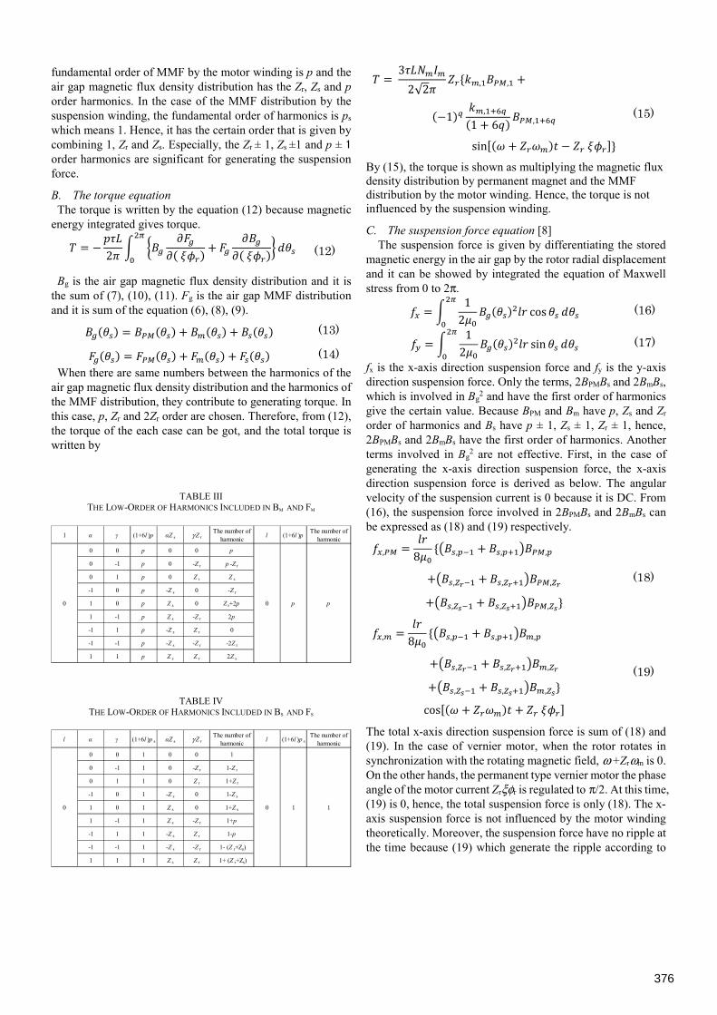
The result of torque analysis is shown in Fig. 4. The horizontal line shows the rotor rotational mechanical angle and the vertical line shows the torque. This analysis is performed at the rated motor current 1.0 Arms without the suspension current. From Fig. 4, the analysis model generates 19.8 N·m average torque and the ripple is 7.0 %. The 120 times torque ripples are involved in the torque wave form per one rotor rotation. That is caused by the second term of (15) with l =1 and large γ.
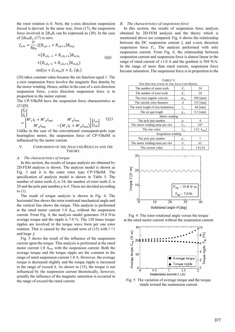
Fig. 5 shows the result of the influence of the suspension current upon the torque. This analysis is performed at the rated motor current 1.0 Arms with the suspension current. Both the average torque and the torque ripple are the constant in the range of rated suspension current 1.0 A. However, the average torque is decreased slightly and the torque ripple is increased in the range of exceed it. As shown in (15), the torque is not influenced by the suspension current theoretically, however, actually the influence of the magnetic saturation is occurred in the range of exceed the rated current.
B. The characteristics of suspension force In this section, the results of suspension force analysis
obtained by 2D-FEM analysis and the theory which is mentioned above are compared. Fig. 6 shows the relationship between the DC suspension current Is and x-axis direction suspension force Fx. The analysis performed with only suspension current. From Fig. 6, the relationship between suspension current and suspension force is almost linear in the range of rated current of ±1.0 A and the gradient is 569 N/A. In the range of more than rated current, suspension force become saturation. The suspension force is in proportion to the
Fig. 5 The variation of average torque and the torque ripple toward the suspension current
Fig. 4 The rotor rotational angle versus the torque at the rated motor current without the suspension current
TABLE V THE SPECIFICATION OF THE ANALYSIS MODEL
The number of stator teeth Z s 24
The number of rotor teeth Z r 20
The rotor angular velocity ω m 200 [rpm]
The outside rotor diameter d 135 [mm]
The stack length of iron lamination l a 60 [mm]
The air gap length g a 0.5 [mm]
The pole pair number p 4The motor winding turns per slot N m 247
The rms value I m 1.0 [ Arms]
The pole pair number p s 1
The motor winding turns per slot N s 61
The current value I s 1.0 [A]
Motor winding
Suspension winding
377
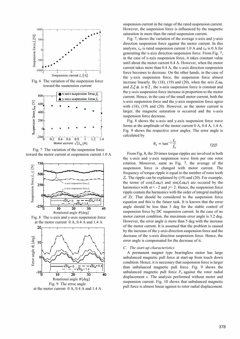
suspension current in the range of the rated suspension current. However, the suspension force is influenced by the magnetic saturation in more than the rated suspension current.
Fig. 7, shows the variation of the average x-axis and y-axis direction suspension force against the motor current. In this analysis, isa is rated suspension current 1.0 A and isb is 0 A for generating the x-axis direction suspension force. From Fig. 7, in the case of x-axis suspension force, it takes constant value until about the motor current 0.4 A. However, when the motor current takes more than 0.4 A, the x-axis direction suspension force becomes to decrease. On the other hands, in the case of the y-axis suspension force, the suspension force almost increase linearly. By (18), (19) and (20), when the ω is Zrωm and Zrξ φr. is π/2 , the x-axis suspension force is constant and the y-axis suspension force increase in proportion to the motor current. Hence, in the case of the small motor current, both the x-axis suspension force and the y-axis suspension force agree with (18), (19) and (20). However, as the motor current is larger, the magnetic saturation is occurred and the x-axis suspension force decrease.
Fig. 8 shows the x-axis and y-axis suspension force wave forms at the amplitude of the motor current 0 A, 0.4 A, 1.4 A. Fig. 9 shows the respective error angles. The error angle is calculated by
From Fig. 8, the 20 times torque ripples are involved in both the x-axis and y-axis suspension wave form per one rotor rotation. Moreover, same as Fig. 7, the average of the suspension force is changed with motor current. The frequency of torque ripple is equal to the number of rotor teeth Zr. The ripple can be explained by (19) and (20). For example, the terms of cos(Zrωmt) and sin(Zrωmt) are occured by the harmonics with α = - 2 and γ = 2. Hence, the suspension force ripple contain the harmonics with the order of integral multiple of Zr. That should be considered to the suspension force equation and this is the future task. It is known that the error angle should be less than 5 deg for the stable control of suspension force by DC suspension current. In the case of no motor current condition, the maximum error angle is 3.2 deg. However, the error angle is more than 5 deg with the increase of the motor current. It is assumed that the problem is caused by the increase of the y-axis direction suspension force and the decrease of the x-axis direction suspension force. Hence, the error angle is compensated for the decrease of it.
C. The start-up characteristics A permanent magnet type bearingless motor has large
unbalanced magnetic pull force at start-up from touch down condition. Hence, it is necessary that suspension force is larger than unbalanced magnetic pull force. Fig. 9 shows the unbalanced magnetic pull force Fu against the rotor radial displacement x. The analysis performed without motor and suspension current. Fig. 10 shows that unbalanced magnetic pull force is almost linear against to rotor radial displacement.
= tan (22)
Fig. 9 The erroe angle at the motor current 0 A, 0.4 A and 1.4 A
Fig. 8 The x-axis and y-axis suspension force at the motor current 0 A, 0.4 A and 1.4 A
Fig. 7 The variation of the suspension force toward the motor current at suspension current 1.0 A
Rotational angle θ [deg]
Err
or a
ngle
θe [
deg]
Rotational angle θ [deg]
Sus
pens
ion
forc
e f x
, fy
[N]
x-axis suspension force fx
y-axis suspension force fy
Fig. 6 The variation of the suspension force toward the suspension current
378
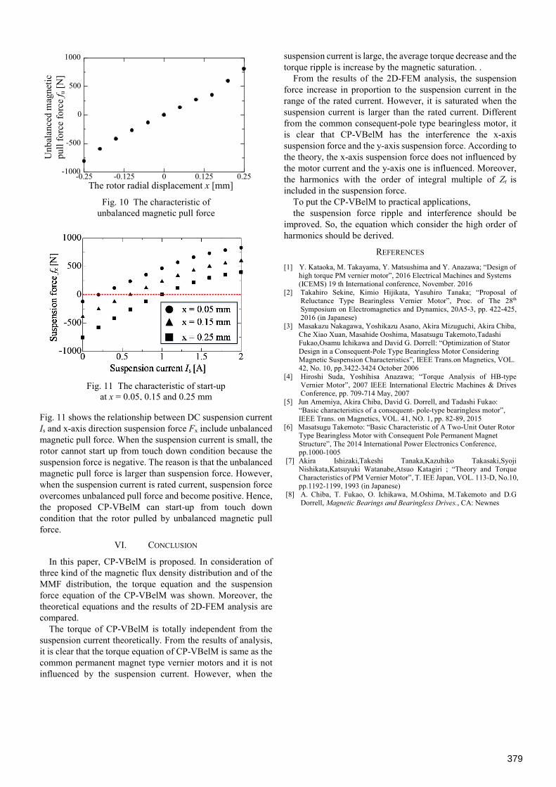
Fig. 11 shows the relationship between DC suspension current Is and x-axis direction suspension force Fx include unbalanced magnetic pull force. When the suspension current is small, the rotor cannot start up from touch down condition because the suspension force is negative. The reason is that the unbalanced magnetic pull force is larger than suspension force. However, when the suspension current is rated current, suspension force overcomes unbalanced pull force and become positive. Hence, the proposed CP-VBelM can start-up from touch down condition that the rotor pulled by unbalanced magnetic pull force.
VI. CONCLUSION
In this paper, CP-VBelM is proposed. In consideration of three kind of the magnetic flux density distribution and of the MMF distribution, the torque equation and the suspension force equation of the CP-VBelM was shown. Moreover, the theoretical equations and the results of 2D-FEM analysis are compared.
The torque of CP-VBelM is totally independent from the suspension current theoretically. From the results of analysis, it is clear that the torque equation of CP-VBelM is same as the common permanent magnet type vernier motors and it is not influenced by the suspension current. However, when the
suspension current is large, the average torque decrease and the torque ripple is increase by the magnetic saturation. .
From the results of the 2D-FEM analysis, the suspension force increase in proportion to the suspension current in the range of the rated current. However, it is saturated when the suspension current is larger than the rated current. Different from the common consequent-pole type bearingless motor, it is clear that CP-VBelM has the interference the x-axis suspension force and the y-axis suspension force. According to the theory, the x-axis suspension force does not influenced by the motor current and the y-axis one is influenced. Moreover, the harmonics with the order of integral multiple of Zr is included in the suspension force.
To put the CP-VBelM to practical applications, the suspension force ripple and interference should be
improved. So, the equation which consider the high order of harmonics should be derived.
REFERENCES
[1] Y. Kataoka, M. Takayama, Y. Matsushima and Y. Anazawa; “Design of high torque PM vernier motor”, 2016 Electrical Machines and Systems (ICEMS) 19 th International conference, November. 2016
[2] Takahiro Sekine, Kimio Hijikata, Yasuhiro Tanaka; “Proposal of Reluctance Type Bearingless Vernier Motor”, Proc. of The 28th Symposium on Electromagnetics and Dynamics, 20A5-3, pp. 422-425, 2016 (in Japanese)
[3] Masakazu Nakagawa, Yoshikazu Asano, Akira Mizuguchi, Akira Chiba, Che Xiao Xuan, Masahide Ooshima, Masatsugu Takemoto,Tadashi Fukao,Osamu Ichikawa and David G. Dorrell: “Optimization of Stator Design in a Consequent-Pole Type Bearingless Motor Considering Magnetic Suspension Characteristics”, IEEE Trans.on Magnetics, VOL. 42, No. 10, pp.3422-3424 October 2006
[4] Hiroshi Suda, Yoshihisa Anazawa; “Torque Analysis of HB-type Vernier Motor”, 2007 IEEE International Electric Machines & Drives Conference, pp. 709-714 May, 2007
[5] Jun Amemiya, Akira Chiba, David G. Dorrell, and Tadashi Fukao: “Basic characteristics of a consequent- pole-type bearingless motor”, IEEE Trans. on Magnetics, VOL. 41, NO. 1, pp. 82-89, 2015
[6] Masatsugu Takemoto: “Basic Characteristic of A Two-Unit Outer Rotor Type Bearingless Motor with Consequent Pole Permanent Magnet Structure”, The 2014 International Power Electronics Conference, pp.1000-1005
[7] Akira Ishizaki,Takeshi Tanaka,Kazuhiko Takasaki,Syoji Nishikata,Katsuyuki Watanabe,Atsuo Katagiri ; “Theory and Torque Characteristics of PM Vernier Motor”, T. IEE Japan, VOL. 113-D, No.10, pp.1192-1199, 1993 (in Japanese)
[8] A. Chiba, T. Fukao, O. Ichikawa, M.Oshima, M.Takemoto and D.G Dorrell, Magnetic Bearings and Bearingless Drives., CA: Newnes
Fig. 11 The characteristic of start-up at x = 0.05, 0.15 and 0.25 mm
Fig. 10 The characteristic of unbalanced magnetic pull force
-0.25 -0.125 0 0.125 0.25-1000
-500
0
500
1000U
nbal
ance
d m
agne
tic
pull
for
ce f
orce
f u [
N]
The rotor radial displacement x [mm]
379