Embed Size (px)
Citation preview

IEEE PC62.92.5/D4, May 2008
IEEE PC62.92.5™/D 4Draft Guide for the Application of Neutral Grounding in Electrical Utility Systems, Part V - Transmission Systems and Subtransmission Systems
Prepared by the Neutral Grounding Working Group of the
Surge Protective Devices Committee
Copyright © 2008 by the Institute of Electrical and Electronics Engineers, Inc.Three Park AvenueNew York, New York 10016-5997, USAAll rights reserved.
This document is an unapproved draft of a proposed IEEE Standard. As such, this document is subject to change. USE AT YOUR OWN RISK! Because this is an unapproved draft, this document must not be utilized for any conformance/compliance purposes. Permission is hereby granted for IEEE Standards Committee participants to reproduce this document for purposes of IEEE standardization activities only. Prior to submitting this document to another standards development organization for standardization activities, permission must first be obtained from the Manager, Standards Licensing and Contracts, IEEE Standards Activities Department. Other entities seeking permission to reproduce this document, in whole or in part, must obtain permission from the Manager, Standards Licensing and Contracts, IEEE Standards Activities Department.
IEEE Standards Activities DepartmentStandards Licensing and Contracts445 Hoes Lane, P.O. Box 1331Piscataway, NJ 08855-1331, USA
Copyright © 2008 IEEE. All rights reserved.This is an unapproved IEEE Standards Draft, subject to change.
1
1
2
3
4
5
6
7
89
1011
121314151617181920
2122232425
23

IEEE C62.92.5/D4, May 2008
Abstract: Basic factors and general considerations in selecting the class and means of neutral grounding for a particular ac transmission or subtransmission system are covered. An apparatus to be used to achieve the desired grounding is suggested, and methods for specifying the grounding devices are given. Transformer tertiary systems, equipment-neutral grounding, and the effects of series compensation on grounding are discussedKeywords: electrical utility systems, equipment neutral grounding, grounding, neutral grounding, subtransmission systems, transformer tertiary systems, transmission systems, series compensation
Copyright © 2008 IEEE. All rights reserved.This is an unapproved IEEE Standards Draft, subject to change.
ii
1
1234567
23

IEEE C62.92.5/D4, May 2008
Introduction(This introduction is not part of IEEE PC62.92.5/D4, Draft Guide for the Application of Neutral Groundingin Electrical Utility Systems, Part V - Transmission Systems and Subtransmission Systems.)
This guide is a part of a series on neutral grounding in electrical utility systems. When the series of documents were first approved and published, they replaced IEEE Std.143-1954, IEEE Guide for Ground-Fault Neutralizers, Grounding of Synchronous Generator Systems, and Neutral Grounding of Transmission Systems. In this series of documents, individual considerations and practices have been given to the grounding of synchronous generator systems, generator-station auxiliary systems, and distribution systems. IEEE Std.143-1954 is a revision of AIEE No. 954, October 1954, which was a compilation of the following three AIEE Transaction papers:
AIEE Committee Guide Report, “Application of Ground-Fault Neutralizers,” AIEE Transactions (Power Apparatus and Systems), vol. 72, pt. III, pp. 183–190, April 1953.
AIEE Committee Report, “Application Guide for the Grounding of Synchronous Generator Systems,” AIEE Transactions (Power Apparatus and Systems), vol. 72, pt. III, pp. 517–530, June 1953.
AIEE Committee Report, “Application Guide on Methods of Neutral Grounding of Transmission Systems,” AIEE Transactions (Power Apparatus and Systems), vol. 72, pt. III, pp. 663-668, June 1953.
The contents of Parts I–V of the revision of IEEE Std.143-1954 are based on the foregoing documents but are amplified and updated with new material from the IEEE tutorial course “Surge Protection in Power Systems” (79H0144-6-PWR) and other sources. In Parts I through V of this series, emphasis is on power system grounding practices as con trasted with the grounding, for example, of industrial systems, which is covered in other guides and standards. These guides and standards should be referenced, when appropriate, to gain a full picture of other grounding practices. It is impossible to give recognition to all those who have contributed to the technology and practices of grounding of power systems, since work involving the preparation of this guide has been in progress for over 30 years. However, the assistance of members, past and present, of the Neutral Grounding Devices Subcommittee of the Surge-Protective Devices Committee, and other similar groups with comparable purposes, should be acknowledged.
Disclaimer
This guide is specifically written for electrical utility systems and does not recognize the neutral grounding requirements for dispersed storage and generation. These requirements must recognize the restrictions imposed by the specific network to which the dispersed storage or generation is connected. Neutral grounding of dispersed storage and generation needs to be coordinated with the electrical utility system.
This guide is a revision of IEEE Std. C62.92.5-1992 (R2001). The changes include addressing all comments received in the most recent reaffirmation of this guide.
Laws and regulations
Users of these documents should consult all applicable laws and regulations. Compliance with the provisions of this standard does not imply compliance to any applicable regulatory requirements. Implements of the standard are responsible for observing or referring to the applicable regulatory requirements. IEEE does not, by the publication of its standards intend to urge action that is not in compliance with applicable laws, and these documents may not be construed as doing so.
Copyright © 2008 IEEE. All rights reserved.This is an unapproved IEEE Standards Draft, subject to change.
iii
1
123456789
1011
1213
1415
1617
181920212223242526272829
30
31323334
353637
38
3940414243
23

IEEE C62.92.5/D4, May 2008
Copyrights
This document is copyrighted by the IEEE. It is made available for a wide variety of both public and private uses. These include both use, by reference, in laws and regulations, and use in private self-regulation, standardization, and the promotion of engineering practices and methods. By making this document available for use and adoption by public authorities and private users, the IEEE does not waive any rights in copyright to this document.
Updating of IEEE documents
Users of IEEE standards should be aware that these documents may be superseded at any time by the issuance of new editions or may be amended from time to time through the issuance of amendments, corrigenda, or errata. An official IEEE document at any point in time consists of the current edition of the document together with any amendments, corrigenda, or errata then in effect. In order to determine whether a given document is the current edition and whether it has been amended through the issuance of amendments, corrigenda, or errata, visit the IEEE Standards Association Web site at
http://ieeexplore.ieee.org/xpl/standards.jsp
or contact the IEEE at the address listed previously.
For more information about the IEEE Standards Association or the IEEE standards development process, visit the IEEE-SA website at http://standards.ieee.org.
Patents
Attention is called to the possibility that implementation of this guide may require use of subject matter covered by patent rights. By publication of this guide, no position is taken with respect to the existence or validity of any patent rights in connection therewith. The IEEE shall not be responsible for identifying patents or patent applications for which a license may be required to implement an IEEE standard or for conducting inquiries into the legal validity or scope of those patents that are brought to its attention.
Copyright © 2008 IEEE. All rights reserved.This is an unapproved IEEE Standards Draft, subject to change.
iv
1
1
23456
7
89
10111213
14
15
1617
18
192021222324
23

IEEE C62.92.5/D4, May 2008
Participants
At the time this draft guide was completed, the Neutral Grounding Working Group had the following membership:
Steven G. Whisenant, Chair
Michael ChampagneTom FieldRandy GoodrichSteven HensleyDavid W. JacksonJoseph L. Koepfinger
Rusty RobbinsThomas RozekKeith StumpEva TarasiewiczEd TaylorRao Thallman
Larry VogtReigh WallingFrank WatererJim WilsonJon Woodworth
The following members of the balloting committee voted on this guide. Balloters may have voted for approval, disapproval, or abstention.
(to be supplied by IEEE)
Copyright © 2008 IEEE. All rights reserved.This is an unapproved IEEE Standards Draft, subject to change.
v
1
1
2
3456
789
10111213
141516171819
2021222324
252627282930
23

IEEE PC62.92.5/D4, May 2008
CONTENTS
1. Scope............................................................................................................................................................1
2. Normative references....................................................................................................................................1
3. General considerations.................................................................................................................................2
4. Transmission system grounding...................................................................................................................2
4.1 General...................................................................................................................................................24.2 Control of overvoltages produced by ground faults and degree of surge-voltage protection with surge arresters........................................................................................................................................................34.3 Control of ground fault currents............................................................................................................74.4 Sensitivity, operating time, and selectivity of the grounding relaying..................................................8
5. Subtransmission system grounding..............................................................................................................8
5.1 General...................................................................................................................................................85.2 Control of overvoltages produced by ground faults and degree of surge voltage protection with surge arresters......................................................................................................................................................105.3 Control of ground fault currents..........................................................................................................125.4 Sensitivity, operating time, and selectivity of the grounding relaying................................................15
6. Transformer tertiary systems......................................................................................................................16
7. Equipment neutral grounding.....................................................................................................................17
7.1 Shunt capacitor banks..........................................................................................................................177.2 High voltage shunt reactors.................................................................................................................197.3 Tapped substation transformers...........................................................................................................19
8. Series-compensated transmission lines......................................................................................................20
Annex A (informative) Specifying a grounding device for a transmission or a subtransmission system (examples)......................................................................................................................................................22
A.1 General................................................................................................................................................22A.2 Specifying a grounding transformer bank..........................................................................................24A.3 Specifying a neutral grounding resistor..............................................................................................25A.4 Specifying a neutral grounding reactor...............................................................................................27A.5 Specifying a ground fault neutralizer.................................................................................................28
Annex B (informative) Zero sequence impedance equivalent circuit for an autotransformer with an impedance-grounded neutral and a delta-connected tertiary..........................................................................30
Annex C (informative) Bibliography.............................................................................................................34
C.1 General................................................................................................................................................34
Copyright © 2008 IEEE. All rights reserved.This is an unapproved IEEE Standards Draft, subject to change.
iii
1
1
2
3
4
5
6789
10
11
1213141516
17
18
192021
22
2324
2526272829
3031
32
33
23

IEEE PC62.92.5/D4, May 2008
C.2 Effect of system grounding on transient overvoltages........................................................................35C.3 Neutral inversion and instability.........................................................................................................35C.4 Effects of equipment-neutral grounding.............................................................................................36C.5 Series compensation of transmission lines.........................................................................................37
Copyright © 2008 IEEE. All rights reserved.This is an unapproved IEEE Standards Draft, subject to change.
iv
1
12345
23

IEEE PC62.92.5/D4, May 2008
Draft Guide for the Application of Neutral Grounding in Electrical Utility Systems, Part V - Transmission Systems and Subtransmission Systems
1. Scope
The scope of this document is to give the basic factors and general considerations in selecting the class and means of neutral grounding for a particular ac transmission or sub-transmission system, and the suggested method and apparatus to be used to achieve the desired grounding. Definitions of grounding terms used in this part of the guide can be found in IEEE Std. C62.92.1-2000 (R2005).
The purpose of this document is to provide the user with insight on the basic factors and general considerations in selecting the class and means of neutral grounding for a particular ac transmission or subtransmission system. An apparatus to achieve the desired grounding is suggested, and methods for specifying the grounding devices are given.
2. Normative references
The following referenced documents are indispensable for the application of this document. For dated references, only the edition cited applies. For undated references, the latest edition of the referenced document (including any amendments or corrigenda) applies.
IEEE Std.C62.92.1-2000 (R2005), IEEE Guide for the Application of Neutral Grounding in Electrical Utility Systems, Part I—Introduction (ANSI).1 2
IEEE 1313.1-1996 (R2002), IEEE Standard for Insulation Coordination – Definitions, Principles and Rules.
IEEE Std.32-1972 (R1997), IEEE Standard Requirements, Terminology, and Test Procedures for Neutral Grounding Devices (ANSI).
IEEE Std. C62.11-2005, IEEE Standard for Metal-Oxide Surge Arresters for AC Power Circuits (ANSI).
1 ? IEEE publications are available from the Institute of Electrical and Electronics Engineers, Service Center, 445 Hoes Lane, P.O. Box 1331, Piscataway, NJ 08855-1331, USA
2 ? The IEEE standards or products referred to in this clause are trademarks of the Institute of Electrical and Electronics Engineers, Inc.
Copyright © 2008 IEEE. All rights reserved.This is an unapproved IEEE Standards Draft, subject to change.
1
1
1
2
3
4
5
6789
1011121314
15
161718192021
2223
2425
26
234567
89

IEEE PC62.92.5/D4, May 2008
IEEE Std.C62.22-1997, IEEE Guide for the Application of Metal-Oxide Surge Arresters for Alternating-Current Systems (ANSI).
3. General considerations
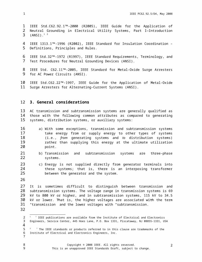
AC transmission and subtransmission systems are generally qualified as those with the fol lowing common attributes as compared to generating systems, distribution systems, or auxiliary systems:
a) With some exceptions, transmission and subtransmission systems take energy from or supply energy to other types of systems (i.e., from generating systems and to distribution systems) rather than supplying this energy at the ultimate utilization point.
b) Transmission and subtransmission systems are three-phase systems.
c) Energy is not supplied directly from generator terminals into these systems; that is, there is an interposing transformer between the generator and the system.
It is sometimes difficult to distinguish between transmission and subtransmission systems. The voltage range in transmission systems is 69 kV to 800 kV or higher, and in subtransmission systems, 115 kV to 34.5 kV or lower. That is, the higher voltages are associated with the term “transmission” and the lower voltages with “subtransmission.”
Generally, the basic factors that have to be evaluated in selecting a grounding scheme for either system are
Control of overvoltages and degree of surge voltage protection with surge arresters
Control of ground-fault currents
Sensitivity, operating time, and selectivity of the ground-fault relaying
These three basic factors can have a considerable influence on system economics, the details of the system design and physical layout, and service continuity.
4. Transmission system grounding
4.1 General
According to IEEE Std. 1313.1-1996 (R2002)1, the AIEE Committee Report, “Application Guide on Methods of Neutral Grounding of Transmission Systems,” [B2] and IEEE Std. 32-1972 (R1997), grounding of the transmission system neutral is an established practice, and in the design of a new system or the revamping of an old one, the question is not “should the neutral be grounded,” but rather “what means of grounding is best suited to the application.”
In systems operating at 115 kV and above, there are strong economic reasons encouraging the use of effective grounding, as explained in IEEE Std.C62.92.1-2000 (R2005). The most significant factors are insulation costs and the lower cost per kilovoltampere of transformers. Neutral grounding affects insulation requirements in two ways. First, the use of effective grounding controls temporary overvoltages due to
1 For information on references, see Clause 2.
Copyright © 2008 IEEE. All rights reserved.This is an unapproved IEEE Standards Draft, subject to change.
2
1
12
3
45
678
9
1011
12
131415161718
19
20
21
22
2324
25
26
2728293031323334353637
2
34

IEEE PC62.92.5/D4, May 2008
ground faults at lower levels than those obtained with other classes of grounding. Second, effective grounding permits the use of lower-rated surge arresters, thereby providing better protection of the insulation against surge voltages.
Many transmission systems consist of multiple voltage levels in which new higher voltage lines are overlaid on an older, lower voltage system. The different voltage levels are usually interconnected through autotransformers. This type of arrangement generally requires that both of the voltage levels be effectively grounded; otherwise, faults on the higher voltage system could impress excessive temporary overvoltages on the lower voltage system. Two-winding transformers could be used if it were desired to have one of the voltage levels non-effectively grounded, but the transformer cost differential encourages the use of autotransformers and effectively grounded systems.
The use of three winding transformers is another method to connect two transmission systems of different voltages together, or to connect a transmission system to a subtransmission system. The transformer can have a wye-delta-wye connection, with the transmission system connected wye and either solidly grounded or grounded through a low impedance. Thus, the transformer is a ground source for both transmission systems. The delta winding may be left idle or may be used to provide station service, to supply capacitor or reactor banks, or to supply a distribution system. This winding should be protected against surges if the terminals of the delta are brought out.
Transmission systems are normally connected to generating systems by means of a delta-wye-connected transformer bank with the generator side connected in delta and the transmission system connected grounded wye. This connection provides a ground source for the transmission system. It also reduces the magnitude of ground-fault current in the generating system.
4.2 Control of overvoltages produced by ground faults and degree of surge-voltage protection with surge arresters
There are two components of voltage or overvoltage in electrical systems when a system ground fault occurs or when a circuit breaker or a switch operates in clearing the ground fault. One of these is the temporary overvoltage or fundamental frequency overvoltage, and the second is the natural frequency voltage, usually of short duration, that is superimposed upon the temporary overvoltage. Since total voltages are of greater interest, the sum of the temporary overvoltage and the natural frequency voltage is commonly used and termed the transient voltage.
4.2.1 Temporary overvoltage (TOV) and arrester rating
The ultimate surge voltage protection is obtained through arrester voltage ratings as low as system grounding conditions will permit during normal and abnormal system conditions. Initially, however, when the surge arrester was adopted as the basic protection device, the equipment design (coordination of major insulating structures) assumed that an “ungrounded neutral” or “100% rated” arrester would be used, unless otherwise specified [IEEE Std. C62.11-2005].
In time, after successful service experience with 100% rated arresters (100% of maximum line-line voltage), it was reasoned that lower rated arresters would be suitable on grounded neutral systems. On these systems, the TOV on the unfaulted phases during a line-to-ground fault would bear the same relationship to arrester rating as “maximum line-line voltage” in an ungrounded system. An “effectively grounded” system was then defined in terms of the symmetrical-component sequence resistances and reactances [IEEE Std. C62.92.1-2000 (R2005)], for which the TOV on an unfaulted phase does not exceed 80% of the maximum line-to-line voltage. Under this condition, an arrester rated at 80% of maximum line-to-line voltage was deemed applicable, and it was classified as a “grounded neutral” arrester.
The use of a “grounded neutral” arrester with lower protective levels enabled designs in some electrical equipment, such as transformers, to have reduced insulation levels with adequate protection. Reduced insulation allowed reduction in size, weight, and cost. Subsequently, still lower rated arresters were
Copyright © 2008 IEEE. All rights reserved.This is an unapproved IEEE Standards Draft, subject to change.
3
1
123456789
101112131415161718192021222324
2526
272829303132
33
343536373839404142434445464748495051
23
IEEE PC62.92.5/D4, May 2008
commonly applied whenever the grounding was significantly better than “effective,” particularly at system voltages where these reductions were significant (above 230 kV).
Usually the TOV produced by a system ground fault is greater than that produced by other causes (generator over speed, ferroresonance, harmonics, etc.). An exception to this might occur on systems where the coefficient of grounding [IEEE Std. C62.92.1-2000 (R2005)] is less than 80%.
The rating of gapped silicon-carbide surge arresters generally exceeded the TOV due to a phase-to-ground fault on the system where it was applied [B10]. This criterion was based on the assumptions that the maximum TOV is produced by a ground fault and that the arrester might operate due to a surge while there was a ground fault on another phase. The arrester had then to seal off against the TOV, which was sustained until the fault was interrupted. There were some arresters that sealed off against voltages higher than their rating. Overvoltage characteristics for these arresters were published in the late 1960s or early 1970s. This feature has sometimes been utilized to provide lower protective levels.
An important consideration for selecting a metal-oxide arrester is the maximum continuous operating voltage (MCOV) [IEEE Std.C62.11-2005]; however, the arrester will also be subjected to TOVs [IEEE Std.C62.22-1997]. A conservative criterion is that the TOV should not exceed the MCOV rating of the arrester [IEEE Std.C62.11-2005]. However, metal-oxide arresters can have thermal capability for TOVs in excess of MCOV rating for specified times, and data and curves of TOV versus allowable time of the overvoltage are available [IEEE Std.C62.11-2005].
The TOVs on the unfaulted phases during line-to-ground and line-to-line-to-ground faults can be ascertained from the coefficient of grounding, which is discussed in Appendix A of IEEE Std.C62.92.1-2000 (R2005). In addition to the formulas presented, curves are provided which show the relationship of the coefficient of grounding (COG) as a function of X0 /X1 and R0 /X1 for various values of R1/X1. From the information presented, it is possible to obtain a comprehensive view of the system TOVs during line-to-ground faults with variations in size and type of neutral impedance.
4.2.2 Effect of system grounding on transient voltage
Curves for transient voltages following faults, in terms of system impedances viewed from the fault, cannot be compiled for the general case as is possible for TOVs. In an actual system, the transient voltages due to fault initiation are affected by the electrical system components and their configuration. As a first approach, however, indications of the maximum transient voltage to be expected can be ascertained from an idealized, lumped circuit without any damping. The maximum transient voltage is then obtained by adding the peak TOV to the peak natural frequency voltage on the assumption that inevitably these two components will have their maximum value at the same instant. Results based on these conditions are shown in Figure 1 as calculated from an idealized symmetrical-component circuit for a single generator and a delta-wye-grounded step-up transformer feeding a faulted transmission line, represented only by its positive- and zero-sequence capacitance [B19], [B25]. XC1 and XC0 on Figures 1 and 2 are the positive-sequence and zero-sequence capacitive reactance, respectively. See A1.4 and IEEE Std.C62.92.1-2000 (R2005).
Copyright © 2008 IEEE. All rights reserved.This is an unapproved IEEE Standards Draft, subject to change.
4
1
123456789
10111213141516171819202122232425262728
29
3031323334353637383940
23

IEEE PC62.92.5/D4, May 2008
Figure 1—Temporary and transient overvoltages as a function of X0/X1
Reprinted with permission from IEEE [B19].
NOTE 1—Magnitudes are maximum voltage-to-ground of unfaulted phases at fault location.
NOTE 2—Solid curves are TOV magnitudes; dotted curves are maximum transient overvoltages.
NOTE 3—Resistance of the system has been neglected.
NOTE 4—Figure 1(a) is for a line-to-ground fault; Figure 1(b) is for a double-line-to-ground fault.
Copyright © 2008 IEEE. All rights reserved.This is an unapproved IEEE Standards Draft, subject to change.
5
1
12
3
4
5
6
7
23
IEEE PC62.92.5/D4, May 2008
Figure 2—Temporary and transient overvoltages for reactive- and resistance-grounded systems
Reprinted with permission from IEEE [B19].
NOTE 1—Magnitudes are maximum voltage-to-ground of unfaulted phases at fault locations.
NOTE 2—X0 = X1; XC0 = XC1.
NOTE 3—Solid curves are TOV magnitudes; dotted curves are maximum transient overvoltages.
NOTE 4—Figure 2(a) is for reactance neutral grounding, 3Xn/X1; Figure 2(b) is for resistance neutral grounding, 3rn/X1
Copyright © 2008 IEEE. All rights reserved.This is an unapproved IEEE Standards Draft, subject to change.
6
1
12
34
5
6
7
8
9
23

IEEE PC62.92.5/D4, May 2008
If resistance is included, hand calculations are possible but are extremely time consuming; therefore, other means have been developed to facilitate finding the solutions to the problem, namely by a Transient Network Analyzer (TNA) or by digital transient analysis computer programs.
Examples of results obtained from a TNA for fault initiation are plotted in Figure 2, showing transient and temporary overvoltages for reactance- and resistance-grounded systems. The data was derived from a TNA study using an idealized three-phase circuit for the same system as for Figure 1 [B19].
The above examples from these studies show the effects of system parameters (including system grounding) on the TOVs and transient voltages of a simplified transmission system. The results indicate that on an effectively grounded system (where X0 /X1 ≤ 3 and R0 /X1 < 1 [IEEE Std.C62.92.1-2000 (R2005)], the transient voltages due to ground faults should be less than two times the normal line-to-neutral voltage, since XC0/X1 is usually well above 10.
4.3 Control of ground fault currents
Transmission systems are normally grounded by grounded-wye transformer banks with delta-connected tertiary or delta-connected secondary windings. In some systems, the zero-sequence impedance is relatively low, and it might be desirable to increase this impedance by installing neutral reactors or operating with some transformer bank neutrals ungrounded. Neutral reactors are not usually installed in autotransformer neutrals. However, if it is determined that one is required; the equivalent zero-sequence impedance diagram for an autotransformer with a neutral reactor and with a delta-connected tertiary is shown in Figure B.2. The neutral of an autotransformer bank should never be operated ungrounded. To do so would allow the zero-sequence voltage from the high-voltage system to be applied directly to the low-voltage system without transformation.
If the zero-sequence impedance of a transformer system is too low, the following undesirable effects can result:
a) The short-circuit duty on power circuit breakers will be greater for ground faults than for three-phase faults (X0 < X1), and it can exceed the breaker rating.
b) The station ground potential can rise excessively with respect to remote ground during ground faults because of a high-magnitude fault current.
c) The system stability margins can be excessively reduced when considering failure of circuit breakers to trip during ground faults.
d) During a ground fault the positive-sequence voltage is reduced and there is a negative-sequence voltage. This effect is greater for lower X0 /X1 ratios. These voltage changes are undesirable because they can produce excessive torques on three-phase machines. In a few situations, low-resistance neutral grounding resistors have been used on generator transformer neutrals to provide damping of torques during ground faults. These systems, however, are still effectively grounded.
e) The zero-sequence voltage during a ground fault is lower for low values of X0 /X1 . This voltage produces operating and polarizing currents in the ground relays at remote terminals and might not be sufficient for positive operation.
These problems have to be studied by the system engineer and an acceptable value of zero-sequence impedance selected to balance the advantages of smaller fault currents against the increase in fault overvoltages in the system.
If neutral reactors or resistors are installed in the transformer neutral, voltage during ground faults should be calculated to see that the transformer neutral and the reactor or resistor are not overstressed. That is, the neutral-to-ground voltage resulting during a fault should not exceed the rated voltage of the transformer
Copyright © 2008 IEEE. All rights reserved.This is an unapproved IEEE Standards Draft, subject to change.
7
1
123456789
10111213
14
15161718192021222324252627
2829
3031
323334353637
383940
41
424344
454647
23

IEEE PC62.92.5/D4, May 2008
neutral.
When a neutral reactor or resistor is used, a surge arrester is usually needed to protect the transformer neutral from voltages due to switching surges from the system or from lightning surges. Lightning striking the station can cause the station ground potential to rise above the potential of the transformer neutral. An arrester with the same voltage rating as the transformer neutral has been frequently used.
If the transformer neutral is ungrounded, it is recommended that the neutral voltage rise during a fault be studied to ensure that the neutral insulation is not overstressed. For example, as shown in Figure 3, if a transformer is connected to a generator or other source on the low-voltage (delta) side, but disconnected from the system on the high-voltage (wye) side, there can be a high TOV on the transformer high-voltage neutral due to a ground fault on the high-voltage side of the transformer. For this reason, a generator transformer neutral with reduced insulation should not be ungrounded. Further, it is recommended that if the transformer neutral is ungrounded, a surge arrester should be provided to protect the neutral from switching and lightning surges, selected for the highest neutral voltage as determined by the study.
Figure 3— Representative system where circuit breaker opening results in a fault on an ungrounded circuit
4.4 Sensitivity, operating time, and selectivity of the grounding relaying
The type of grounding employed on a system has a considerable influence on the type of ground-fault relaying equipment needed. Since transmission systems are generally effectively grounded, they will have maximum phase-to-ground fault currents of the same order of magnitude as their three-phase fault currents and will require rapid clearing to minimize voltage disturbances, instability, high ground potential rises and equipment damage.
5. Subtransmission system grounding
5.1 General
The basic considerations in the grounding of subtransmission systems are not different from those of transmission systems. However, lower voltages employed for subtransmission make insulation costs less significant than in the higher voltage systems. As a result, other types of grounding can be used, although
Copyright © 2008 IEEE. All rights reserved.This is an unapproved IEEE Standards Draft, subject to change.
8
1
1
2345
6789
10111213
141516
17
1819202122
23
24
252627
23

IEEE PC62.92.5/D4, May 2008
effective grounding is most common.
Delta-connected transformer windings are commonly found at subtransmission voltages. For example, in transformers stepping down from the transmission voltage level, the use of a wye-delta connection provides an inexpensive design with adequate third harmonic suppression, and it permits the neutral of the wye connection to serve as a grounding point for the high-voltage system. Transformers stepping down from subtransmission to distribution voltage are frequently delta-wye connected in order to provide a stabilized neutral for four-wire distribution circuits. Many systems, of course, utilize other connections for a variety of reasons, including maintenance of phase relationship and neutral grounding of the subtransmission system.
The abundance of delta connections on subtransmission systems requires that the neutral grounding for the system be adequately planned to ensure that proper grounding is maintained for all expected system operating contingencies. In general, two different types of locations are available for grounding a subtransmission system: the source transformers (stepping down from the transmission voltage) and the load transformers (stepping down to a distribution voltage for large customers). Where a choice is available, the source transformers are the preferred location for grounding. Ideally, a source of ground current should be provided at each source of power to ensure that whenever the system is energized it is properly grounded.
If grounding at the system sources is not convenient or not economical, it is possible to ground the system adequately through the use of wye-connected, high-voltage windings at the load transformers. To do this properly, it is necessary that a number of transformers be wye connected so that, during fault conditions or routine switching, the subtransmission system does not become isolated from its ground sources while still connected to the power source.
If a subtransmission system is connected to another voltage level through an autotransformer, the subtransmission system is usually effectively grounded for the reasons noted in 4.1. Even if the system design is such that effective grounding is not required, there are advantages to consider in its use. First, if a suitable number of wye-connected transformers are available, it is generally the least expensive method. Second, effective grounding permits the use of lower rated surge arresters, which reduces arrester costs and provides maximum protective margins to the equipment insulation. Further economies through the use of reduced equipment insulation levels are possible. Finally, ground-fault relaying on an effectively grounded system is usually the least expensive protection system.
Despite these advantages of effective grounding, there are specific instances in which consideration of other grounding methods is appropriate. If problems such as communication overbuilds or ground potential rise require limitation of the ground-fault current (to less than 60% of three-phase fault current), Low-Resistance Grounding [IEEE Std.C62.92.1-2000 (R2005)] provides an attractive alternative to effective grounding. Transient overvoltages are well controlled with this method, and relaying is similar to that used on effectively grounded systems.
Low-Resistance Grounding can also be less expensive than effective grounding, if grounding transformers are required. Grounding transformers with neutral resistors could have a lower current rating, decreasing costs. Grounding transformers used for this service should have a low enough zero-sequence impedance to meet the required goals [IEEE Std.C62.92.1-2000 (R2005)]. The neutral insulation of the transformer should be rated for system phase-to-neutral voltage.
If grounding transformers without neutral resistors are used to ground the system, the grounding may be Low-Inductance or High-Inductance Grounding [IEEE Std.C62.92.1-2000 (R2005)], depending upon whether the grounding transformer impedance(s) produce an X0/X1 ratio of less than or more than 10. High-Inductance Grounding can have higher transient overvoltages than Low-Resistance Grounding. With High-Inductance Grounding and a possibility of circuit breaker restriking, transient voltages might need to be controlled with surge arresters.
Copyright © 2008 IEEE. All rights reserved.This is an unapproved IEEE Standards Draft, subject to change.
9
1
123456789
10
1112131415161718
1920212223
2425262728293031
323334353637
3839404142
434445464748
23

IEEE PC62.92.5/D4, May 2008
5.2 Control of overvoltages produced by ground faults and degree of surge voltage protection with surge arresters
5.2.1 Temporary overvoltage and surge arrester rating
The voltage rating of surge arresters on a subtransmission system should be based on the maximum continuous operating voltage (MCOV) as well as the magnitude and duration of the maximum TOV. The maximum TOV will usually occur during phase-to-ground faults and can be determined by calculation or from the coefficient of grounding curves in Appendix A of IEEE Std.C62.92.1-2000 (R2005). The MCOV should be determined for all contingency conditions and can be especially of concern during light-load conditions or where high-voltage capacitor banks are present.
5.2.2 Effect of system grounding on transient voltage
If the subtransmission system is not effectively grounded, the transient voltages due to a ground fault will be somewhat higher than if the system were effectively grounded. An approximation of these voltages can be made from Figures 1 and 2. More accurate determination of the transient voltages can be made with available computer programs. Surge arresters limit high transient voltages; however, their discharge energy capability must not be exceeded.
An intermittent conductor-to-ground arcing fault was often referred to as an “arcing ground” in the early technical papers on ungrounded neutral operation. Theories were given to show how an “arcing ground” could have caused apparatus breakdowns. Apparatus failures were more frequent in this early period, but inadequate insulation strength or inadequate surge protection was probably more often the cause of the trouble rather than the “arcing ground.”
An arcing fault, to produce an extremely high overvoltage, has to occur in a medium where the dielectric strength in the arc path increases for each restrike of the arc following its repeated extinction, resulting in higher and higher voltages being obtained on successive restrikes. Field tests on actual systems during arcs to ground failed to produce these high overvoltages. This supports the conclusion that the mechanism for producing these high overvoltages is not available for an arc in air or in a solid dielectric [B17], [B20], [B22], [B23], [B24].
Reignitions or restrikes in a switch or a circuit breaker can produce high overvoltages [B21]. When the contacts part and there is a current zero, either forced by the arc voltage or naturally occurring, there is a race between dielectric strength buildup of the open gap and the transient recovery voltage across the gap. If the transient voltage across the gap is faster than the dielectric strength build up within the first quarter cycle, the gap reignites, and breaker current continues until the next current zero and the race repeats. This is normal and the gap should reignite if it cannot interrupt the current. In many cases the first current interruption might be hardly noticed.
Restrikes tend to occur when the voltage cross the breaker gap builds up slowly, the interruption is too easy, and the gap does not reconduct (restrike) until more than a quarter cycle after initial current zero. The classic example of this is voltage doubling during capacitor bank de-energization. When the contacts open and a natural current zero occurs no immediate voltage tends to develop across the contacts and no reignition occurs. The voltage across the contacts develops as a power frequency 1 - cos ω t wave and a half-cycle later there is a two per unit voltage across the contacts. If the breaker restrikes at this two per unit time, the capacitor voltage quickly reverses and overshoots to three per unit. The next maximum voltage across the contacts will be five per unit. Another restrike can occur and the process will continue until something fails. This was more of a problem for air-magnetic and oil breakers than for modern gas and vacuum breakers.
Copyright © 2008 IEEE. All rights reserved.This is an unapproved IEEE Standards Draft, subject to change.
10
1
12
3
456789
10
1112131415
1617181920
212223242526
27282930313233
34353637383940414243
23

IEEE PC62.92.5/D4, May 2008
Reignitions are usually of little consequence in so far as generating overvoltages during the interruption process; however, this is not true for a circuit breaker which is prone to restrikes since this process can generate significant overvoltages, which might need to be controlled by applying sure arresters.
The maximum overvoltage caused by restrikes of switches is a function of the system neutral grounding. The highest overvoltages occur on the ungrounded neutral system. Overvoltages in the ground-fault neutralizer system are next in severity [IEEE Std.C62.92.1-2000 (R2005)]. Effectively grounded systems, low-inductance grounded systems, and low-resistance systems have the lowest transient overvoltages [IEEE Std.C62.92.1-2000 (R2005)], [B21]. But when the reactance ratio X0/X1 exceeds 10, high transient overvoltages can occur [IEEE Std.C62.92.1-2000 (R2005)].
The results of a TNA study done in 1954 [B18] showed the effects of resistance grounding in subtransmission systems on the line-to-ground transient overvoltages caused during restrikes in a circuit breaker interrupting a line-to-ground fault. Two restrikes were simulated at points in time to give the highest overvoltages. The purpose of the study was to determine the value of resistance that would limit the transient overvoltages to less than three times normal line-to-ground voltage. Three times per unit was chosen because this value was, at that time, the approximate switching-surge sparkover voltage of an ungrounded-neutral-rated, gapped, surge arrester.
Results of the TNA study are shown in Figures 4 and 5 and indicate the following:
a) For grounding conditions in which X0 /X1 ≥ 10, the use of the neutral grounding resistor reduces the recovery voltage across the contacts of the interrupting circuit breaker, thereby reducing the probability of restriking and cumulative build-up in voltage, either on the faulted phase or on unfaulted phases.
b) On most systems, if the grounding conditions are such that R0 /X0 ≥ 2, the transient overvoltages that result from restriking in a circuit breaker that interrupts a line-to-ground fault will not exceed 3.0 per unit regardless of the ratio X0/X1.
c) System conditions involving values of R0 /X0 ≥ 15 can result in transient overvoltages near 3.0 per unit when the ratio XC0 /X1 is around 150 or 200.
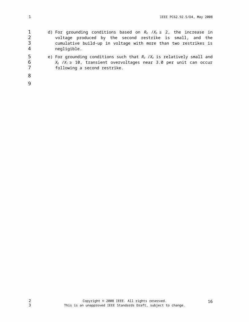
d) For grounding conditions based on R0 /X0 ≥ 2, the increase in voltage produced by the second restrike is small, and the cumulative build-up in voltage with more than two restrikes is negligible.
e) For grounding conditions such that R0 /X0 is relatively small and X0 /X1 ≥ 10, transient overvoltages near 3.0 per unit can occur following a second restrike.
Copyright © 2008 IEEE. All rights reserved.This is an unapproved IEEE Standards Draft, subject to change.
11
1
123
456789
10111213141516
17
18192021
222324
2526
272829
3031
32
33
23

IEEE PC62.92.5/D4, May 2008
5.3 Control of ground fault currents
If a subtransmission system is entirely supplied from grounded-wye connected transformers, which include delta-connected windings, the zero-sequence impedance at this ground source will be less than the positive-sequence impedance, and the system will be effectively grounded. Therefore, the single-line-to-ground (SLG) fault current will be larger than the three-phase fault current. A reactor is sometimes installed in the neutral of the grounded-wye winding to reduce the SLG fault current. The transformer neutral and neutral reactor should then be capable of withstanding the voltage across the reactor during ground faults and be protected against transient voltage surges as discussed in 4.3.
If a grounding transformer is used to establish system grounding conditions, a system ground-fault study should be done to size the transformer. The transformer should have sufficiently high reactance so that the current in a nearby fault will not require an excessive kilovoltampere unit size, but low enough reactance to allow adequate current for relaying ground faults at the far end of the circuit. One criterion in determining the maximum grounding transformer impedance is that the ground current for a fault at the most remote point on the circuit should be at least 10% of the three-phase fault current. This criterion should permit X0/X1 ratios as high as 28. But the TOVs on the unfaulted phases during a ground fault should not exceed the capability of the surge arresters on this circuit.
The high inductive reactance of the grounding transformer can cause the R0/X0 ratio to be very small. Unfortunately, the highest transient overvoltages occur when this ratio is zero as shown by Curve A of Figures 4 and 5. Since these overvoltages are of the nature of switching surges, they can be limited in magnitude by surge arresters. However, as mentioned earlier, these overvoltages occur during restriking of the circuit breaker that interrupts the fault. They should not occur as often in modern circuit breakers which have a lower incidence of restrike.
Copyright © 2008 IEEE. All rights reserved.This is an unapproved IEEE Standards Draft, subject to change.
12
1
1
23456789
1011121314151617181920212223
23

IEEE PC62.92.5/D4, May 2008
Figure 4—Effect of Resistance grounding on line-to-ground transient overvoltages caused by two circuit breaker restrikes, X0/X1 = 30
Reprinted with permission from IEEE [B18].
NOTE—R0/X0 for Curve A = 0, B = 1, C = 2, D = 5, E = 10 and F = 20.
Copyright © 2008 IEEE. All rights reserved.This is an unapproved IEEE Standards Draft, subject to change.
13
1
123
4
5
23

IEEE PC62.92.5/D4, May 2008
Figure 5—Effect of Resistance Grounding on Line-to-Ground Transient Overvoltages Caused by Two Circuit-Breaker Restrikes, C1/C0 = 1.6
Reprinted with permission from IEEE [B18].
NOTE—R0/X0 for Curve A = 0, B = 1, C = 2, D = 5, E = 10, and F = 20.
A grounding transformer selected by the above criterion will have maximum impedance and minimum kilovoltampere rating. However, very high values of reactance should be avoided to prevent harmonic resonance from occurring between the zero-sequence capacitance of the system and the zero-sequence inductance of the grounding transformer. Usually the third harmonic frequency is of most concern, but other triple harmonics should be considered.
Reducing both the size of the grounding transformer and the transient overvoltages can be accomplished by
Copyright © 2008 IEEE. All rights reserved.This is an unapproved IEEE Standards Draft, subject to change.
14
1
123
4
5
6789
101112
13
23

IEEE PC62.92.5/D4, May 2008
installing a resistor in the neutral of the grounding transformer such that R0/X0 ≥ 2.
The fault current, however, should still be at least 10% of the three-phase value for faults anywhere in the circuit. Curves C, D, E, and F in Figures 4 and 5 show that the transient overvoltages are considerably less than three per unit when R0/X0 ≥ 2.
If low-resistance grounding is used, economics generally dictate that the grounding resistance limit the ground-fault current to a range of 10–25% of the three-phase fault current. Again, the lower range of 10% is established by the minimum current requirements for relaying, and the upper range of 25% by the cost of the resistor as dictated by the watts loss in the resistor and the cost relative to that of reactive grounding.
5.4 Sensitivity, operating time, and selectivity of the grounding relaying
Sub-transmission systems with very low levels of ground-fault current, such as ungrounded, high-resistance grounded, and neutralizer grounded [IEEE Std.C62.92.1-2000 (R2005)], are often not equipped with ground-fault relaying. However, there are relaying systems that can provide selective ground-fault protec-tion. Alternatively, the systems may have a temporary grounding device actuated by the ground fault to develop enough ground-fault current for clearing by conventional relays.
Low-resistance and effectively grounded systems for subtransmission networks are generally designed to permit the use of conventional ground relays.
Copyright © 2008 IEEE. All rights reserved.This is an unapproved IEEE Standards Draft, subject to change.
15
1
1
234
5678
9
1011121314
1516
17
23

IEEE PC62.92.5/D4, May 2008
6. Transformer tertiary systems
The delta-connected tertiaries of autotransformers or wye-wye power transformers can be used within the substation for various purposes. Among these are:
a) Connection of shunt capacitors or reactors for voltage control
b) Connection of synchronous condensers
c) Station service supply
Although these tertiary voltage systems are generally within the distribution voltage class (5–35 kV), the neutral grounding requirements are usually different from those of a utility distribution system. Because of the very limited extent of the system, the delta connection of the source, and the absence of a need for four-wire service, there is little reason to effectively ground such systems. In addition, the very high short-circuit duty available on many tertiaries would require a very expensive, high-capacity grounding transformer in order to produce an X0 /X1 ratio of less than 3.0.
As a result of these considerations, tertiary systems are often designed as nominally ungrounded systems. Because of their limited extent, the system zero-sequence capacitance is small, unless cable is used, and these systems are unlikely to suffer from the severe overvoltage problems that sometimes afflict large ungrounded systems.
If the tertiary voltage system is to be operated ungrounded, then the neutrals of connected apparatus such as reactors, capacitors, and station service transformers should also be ungrounded. If these were to be grounded, the character of the system grounding would be changed depending on whether the apparatus is in service. In particular, grounded capacitor banks should be avoided because of the overvoltage associated with ground faults on capacitively grounded systems.
Where synchronous condensers or other large machines are connected directly to the tertiary system, the grounding requirements of the machine have to be considered. The generator grounding standard, IEEE Std. C62.92.2-1989 (R2000) [B11] contains information applicable to such installations.
In most instances, it will be desirable to provide a ground detector to detect the presence of an accidental ground on the tertiary voltage system. This detector will usually take the form of a voltage relay supplied from either a single-line-to-ground voltage transformer or three voltage transformers connected in wye-broken delta configuration. On tertiary systems of limited extent, such voltage transformer installations can be subject to neutral inversion [B27], [B28], [B30] or neutral instability [B26], [B27], [B28], [B29], [B31]. In the more common case of three voltage transformers, neutral instability can generally be eliminated by the proper application of a resistance burden across the broken delta secondary [B28], [B30] or in the primary neutral.
The addition of a resistance burden across the broken delta secondary to prevent ferro-non-linear oscillations has two additional benefits. First, the resistance burden tends to damp out possible overvoltages caused by intermittent arcing faults to ground. Optimum performance in this regard requires that the installation meet the high resistance grounding criterion: the watts loss in the resistor during a solid phase-to-ground fault equals or exceeds the VARs supplied by 3Cg (the sum of the three system phase-to-ground capacitances). Care should be taken to insure that the voltage and power ratings of the voltage transformers and the resistance burden are not exceeded when the tertiary system is grounded by a single line-to-ground fault.
The second benefit of resistance loading of the secondary delta of the voltage transformers is the tendency of the loading to stabilize the neutral of the system under normal conditions; i.e., to equalize the magnitude
Copyright © 2008 IEEE. All rights reserved.This is an unapproved IEEE Standards Draft, subject to change.
16
1
1
23
4
5
6
7
89
10111213141516171819202122232425262728293031323334
3536373839404142
4344
23

IEEE PC62.92.5/D4, May 2008
of the three phase-to-ground voltages. Without resistance loading, the phase-to-ground voltages are determined solely by the relative values of the three phase-to-ground capacitances.
These capacitances can be quite unequal because of the absence of transpositions inherent in bus structures. Unbalance of the voltages to ground is undesirable, since it will tend to cause the ground detector to indicate a system ground fault when none is present. The stabilizing effect of the secondary resistance is particularly important when the source transformers are composed of single-phase units that may not have equal capacitances from the tertiary winding to ground. This can occur even for transformers whose principal electrical characteristics are similar but that were produced by different manufacturers. A common situation producing this problem is the use of a non-identical spare transformer in a bank normally consisting of identical units.
7. Equipment neutral grounding
In addition to the basic decision of how a system is to be grounded, questions arise from time to time about neutral grounding of specific pieces of apparatus connected to the system. On effectively grounded systems, equipment neutral grounding can generally be freely chosen since it will have little or no impact on the character of the system grounding in non-effectively grounded systems. Grounding the neutral of a specific piece of apparatus can change the character of the system grounding and can result in the apparatus rating being exceeded. Careful analysis is required to assess the full significance before a decision is made to install grounded neutral equipment on non-effectively grounded systems.
The following subsections discuss specific pieces of apparatus that are usually wye connected and the specific characteristics of operating these devices with grounded or ungrounded neutrals.
7.1 Shunt capacitor banks
Neutral grounding of shunt capacitor banks has significant effect in several distinct areas, each of which requires consideration in the grounding decision. These areas are
a) Duty on the capacitor switching device
b) Transients created by capacitor switching
c) Harmonic current distribution
d) Capacitor fusing
e) System grounding
These considerations, together with insulation requirements, usually result in the grounding of capacitor banks applied to systems above 115 kV.
7.1.1 Switching duty
Switching duty is addressed by the following standards:
a) IEEE Std.C37.04-1999 [B37]
b) ANSI C37.06-2000 [B32]
c) IEEE Std.C37.012-1979 (R 2000) [B38]
d) IEEE C37.99-2000 [B39]
Copyright © 2008 IEEE. All rights reserved.This is an unapproved IEEE Standards Draft, subject to change.
17
1
12
3456789
10
11
12131415161718
1920
21
2223
24
25
26
27
28
293031
32
333435
36
37
38
23
IEEE PC62.92.5/D4, May 2008
The recovery voltage across the switching device that is de-energizing a capacitor bank is higher (approximately 3 per unit versus 2 per unit) for an ungrounded capacitor bank than for a grounded capacitor bank [B36], [B41]. At transmission and subtransmission voltages, the higher recovery voltage can mean that a given switching device cannot interrupt as large an ungrounded bank as it can a grounded one. At transmission voltages (above 138 kV), devices for switching ungrounded capacitor banks can require special considerations.
7.1.2 Energizing transients
Energizing capacitor banks, particularly when two or more are connected to the same bus, produces a large, high-frequency transient current. When these capacitors are connected in grounded-wye configuration, these transients flow in the station ground grid. The transient ground currents produced by large, high-voltage shunt capacitor banks can induce high voltages into the low-voltage, station control, and protective circuitry and into secondary circuits of current transformers [B34]. Equipment damage and false operation have been reported as being caused by such transients. Special shielding measures and grounding techniques might be required to control these effects, as well as the use of current-limiting reactors in the switched circuit [IEEE C37.99-2000] [B39], [B40].
Transient energizing currents for ungrounded banks are confined to the phase conductors and do not usually induce significant voltages into the control wiring. Transient voltages can appear, however, on the ungrounded neutral [B35]. These can be of importance if an instrument transformer is connected from neutral-to-ground for relay protection of the capacitor bank [B39].
7.1.3 Harmonic currents
For issues related to capacitor bank protection, refer to IEEE Std. C37.99-2000 [B39].
Capacitor banks have a lower impedance at harmonic frequencies than at 60 Hz. As a result, installation of a capacitor bank can cause a redistribution of harmonic current flow on the power system. Capacitor banks do not create harmonic currents, but by changing the apparent impedance of the system at harmonic frequencies, they can redirect the flow of harmonic current drawn by transformers and customer loads.
Harmonic current flow is of interest primarily because of the need to avoid interference in communications circuits that parallel power lines [B33]. The principal interfering harmonics are those of odd triple frequency (180 Hz, 540 Hz, 900 Hz, etc.). When balanced, these triple harmonics are equal and in phase in the three phases and are hence zero-sequence quantities. It is for this reason that they cause the most interference with communication circuits. Since the odd triple-harmonic currents are zero-sequence quantities, they will flow into a capacitor bank only if it has a grounded neutral. Installing a particular grounded capacitor bank can have an adverse effect, a beneficial effect, or no effect on a given inductive coordination problem. A system analysis is required to predict the expected effect of any given installation. An ungrounded bank can be expected to have substantially no effect on triple-harmonic flow.
7.1.4 Capacitor fusing
In ungrounded capacitor banks, the fault current for a shorted capacitor unit is limited by the impedance of the capacitors in the other two phases.
Similarly, in large high-voltage capacitor banks, which consist of several series-connected groups of capacitor units, the maximum fault current is limited by the impedance of the other series groups, regardless of whether the bank neutral is grounded. However, in grounded banks with single-series groups of capacitor units rated at line-to-neutral voltage, the available short-circuit current is equal to the full system phase-to-ground short-circuit current, requiring fuses capable of interrupting this current.
Copyright © 2008 IEEE. All rights reserved.This is an unapproved IEEE Standards Draft, subject to change.
18
1
1234567
8
9101112131415161718192021
22
23242526272829303132333435363738
39
4041
4243444546
23

IEEE PC62.92.5/D4, May 2008
7.1.5 System grounding
Installation of a grounded capacitor bank on an effectively grounded system will, in most cases, have a negligible effect on the system grounding. In unusual cases, such as the installation of a large grounded capacitor bank at a remote station with no grounded transformer banks, the installation should probably be reviewed to ensure that the X0/X1 ratio does not become excessively high and possibly negative, and that directional ground relays will not operate incorrectly due to capacitive current flow to external ground faults.
Grounded capacitor banks should be avoided on systems that are ungrounded, resistance grounded, or resonant grounded [IEEE Std.C62.92.1-2000 (R2005)]. The high voltage on the unfaulted phases of such systems during a ground fault will put an overvoltage on the capacitor units and possibly other apparatus. In addition, the presence of the capacitor bank will greatly increase the system zero-sequence capacitance, emphasizing the transient overvoltage characteristics of ungrounded systems and interfering with the transient suppression properties of resistance grounding.
Where it is desired to use a grounded capacitor bank on an inductance grounded system, the application should be carefully studied to ensure that the capacitor bank does not cause an unacceptable increase in temporary or transient overvoltages.
7.2 High voltage shunt reactors
High-voltage shunt reactors are connected to the lines or buses of many high-voltage systems (230 kV and above) to compensate for the high capacitive charging current of underground cables or long transmission lines. The most economical construction for such reactors is a grounded-wye configuration with the winding insulation graded to a relatively low level (usually 15 kV class, 110 kV BIL) at the neutral grounded end. Since these high-voltage systems are universally effectively grounded, the moderate amount of zero-sequence current contributed by these reactors has no noticeable effect on the system grounding.
In certain applications such as a single-pole tripping on long overhead lines, it might be necessary to install shunt reactors on the line with a neutral reactor so that the zero-sequence impedance is greater than the positive-sequence impedance [B42], [B43], [B44], [B46]. Some high voltage, three-phase reactors are also designed to have higher X0 than X1 [B42][B45]. This is necessary in order to reduce the secondary fault current of such systems (i.e., the fault current that continues to flow after the faulted phase has been opened) in order to allow single-pole reclosing of the circuit breaker. This current is caused by the capacitive coupling between the open phase and the two remaining energized phases. With this additional neutral impedance, the reactor neutral point will have a potential to ground under both ground fault and single-phase open-pole conditions. This value ranges from 30 – 60% of phase-to-neutral voltage on effectively grounded systems, depending on the neutral reactance. This, of course, might require greater insulation at the neutral end of the phase reactors as compared to the solidly grounded case, and it also usually will require the provision of surge protection for the neutral end insulation.
7.3 Tapped substation transformers
When a substation transformer is tapped to or fed directly from a transmission line or subtransmission line, it is common practice to use a delta connection so as not to reduce relay current at the source breaker or breakers during ground faults. If the substation feeds a system that has permanent or temporary backfeed due to large generators or motors, or other transformers with their secondaries connected in parallel (Figure 6), the line will become an ungrounded system when disconnected from the source. If this is due to a permanent ground fault on the line, voltages to ground approaching normal line-to-line voltage can occur on the unfaulted phases. These voltages can exceed insulation levels and arrester ratings on transmission
Copyright © 2008 IEEE. All rights reserved.This is an unapproved IEEE Standards Draft, subject to change.
19
1
1
234567
89
10111213
141516
17
1819202122232425262728293031323334353637
38
39404142434445
23

IEEE PC62.92.5/D4, May 2008
lines that are normally effectively grounded.
Figure 6— A tapped substation resulting in backfeed on a transmission system
NOTE—Figure 6 is presented as an example for illustration. It is not a preferred design.
Accordingly, insulation levels and arrester ratings on a part of the transmission line, which can be backfed from a tapped substation, might have to be raised to levels associated with 100% line-to-line voltage rather than those for the 80% voltage generally used with effectively grounded systems. The determining factor will be how much positive-sequence voltage the generators or motors are able to maintain with the existing loads. The source of backfeed should be tripped as soon as possible.
If a grounded-wye connection is used for the tapped substation transformer, the neutral of the wye will be grounded, usually through a relatively high-impedance neutral reactor. If a subsystem with backfeed is isolated on a section of transmission line, the system will not be ungrounded, but grounded through this reactor. The TOV on unfaulted phases during a ground fault will, therefore, be determined by the positive-sequence voltage that the source of backfeed is able to maintain and by the ratio of Z0/Z1.
8. Series-compensated transmission lines
Series compensation of long high-voltage and extra-high-voltage lines has become almost standard practice [B54]. The presence of series compensation affects the X0/X1 ratios of the system, with the reactance of the series capacitor appearing in all three sequence networks. Therefore, temporary and transient overvoltages as a result of faults, as well as circuit-breaker recovery voltages and surge arrester operation, are different than those that would appear in the uncompensated system[B49], [B51], [B53], [B55], [B56], [B57].
Copyright © 2008 IEEE. All rights reserved.This is an unapproved IEEE Standards Draft, subject to change.
20
1
1
2
345
6789
1011121314151617
18
1920212223
23

IEEE PC62.92.5/D4, May 2008
There have also been concerns about ferroresonant TOVs in series-compensation systems [B50], but few if any cases of ferroresonance have been reported for operating transmission or subtransmission systems. However, because of this concern, some utilities buying series capacitors have specified special subharmonic detection devices as part of the series capacitor bank. There are also concerns about subsynchronous resonance (SSR) of rotating machine mechanical systems with the series-compensated electrical system [B52].
Additional concerns have centered on fundamental-frequency resonance conditions during faults at critical locations in the transmission systems. But economical applications of series capacitors dictate that some means be supplied to limit the overvoltage appearing across the series capacitor during faults to voltages no higher than economical design levels. Limiting this overvoltage virtually eliminates the possibility of high temporary fundamental resonant overvoltages.
The overvoltage protection for series capacitors applied to transmission systems has taken two forms. The earliest forms of overvoltage protection were spark-gap systems [B49], [B54] that limited voltage to the sparkover voltage of the gap setting, which was generally no more than 3.5 times the rated voltage across the series capacitor bank, but often less. More recently, the protection has been achieved by metal-oxide varistors [B47], [B48], somewhat similar to surge arresters but applied across the series capacitor and limiting the voltage to about two times the rated voltage across the series capacitor bank.
Both forms, when acting during a fault, can reduce temporary and transient overvoltages, the spark gap by electrically bypassing the capacitor during its arcing time, and the metal-oxide varistors by limiting the overvoltage, inherently reducing the capacitive reactance, and inserting some value of equivalent resistance into the circuit until the fault is cleared.
The effect on temporary and transient overvoltages (and the possibility of SSR) as a result of using of series compensation with its overvoltage protection should be carefully studied.
Copyright © 2008 IEEE. All rights reserved.This is an unapproved IEEE Standards Draft, subject to change.
21
1
123456
789
1011
121314151617
18192021
2223
24
23

IEEE PC62.92.5/D4, May 2008
Annex A
(informative)
Specifying a grounding device for a transmission or a subtransmission
system (examples)
A.1 General
IEEE Std.32-1972 (R1997)1 has been applied to devices used to control the ground current or the potentials to ground of an alternating-current system. The bases for ratings for such devices include: current, voltage, frequency, basic impulse insulation level (BIL), insulation class, system circuit voltage, indoor and outdoor service conditions, and time ratings.
A.1.1 Current and time ratings
Unless otherwise specified, the basis for the current rating shall be the thermal current; that is, the current through the neutral grounding device during a single-line-to-ground fault at the device location. Implicit in the thermal current rating is an associated continuous current, which, unless otherwise specified, bears a relationship to the thermal rating determined by the rated time of the device. The rated time (or time rating) is the time during which the device will carry its rated thermal current under standard operat ing conditions without exceeding the limitations established by standards [IEEE Std. 32-1972 (R1997)].
Of importance also are the mechanical forces associated with fault currents, especially those forces associated with the crest of the offset current wave. In calculating such currents, subtransient reactance fault conditions are often assumed, but the results will depend on the location of the grounding device within the system.
A method of calculating the thermal current rating is given for each type of grounding device in the following subsections. In order to make this calculation, the value of the zero-sequence impedance of the grounding device and the sequence impedances of the system to a ground fault at the grounding device, as well as the system operating voltage and frequency, are needed. (For further discussion of fault current calculations, see, for example, those parts applying to line-to-ground faults in Clause 5 and Annex A of IEEE Std. C37.010-1999 [B9].)
Rated times are associated with temperature rises within the grounding device when carry ing rated current. IEEE Std. 32-1972 (R1997) specifies that rated times shall be 10 s, 1 min, 10 min, and extended time. The rated-time temperature rises of extended-time devices shall be taken as the ultimate rise above the ambient resulting from the continued flow of rated thermal current (or for certain resistors, the continued application of rated voltage). According to IEEE Std. 32-1972 (R1997), extended-time operation shall not exceed an average of 90 days per year.
A.1.2 Rated frequency
Generally, fundamental system frequency is assumed for the ratings of grounding devices; however, it should be recognized that, in certain transmission or sub-transmission systems, system frequencies can be off nominal for varying periods of time. Such variations are not significant to the rating of grounding
1 Many of the following subsections have been developed based on material taken directly from this reference.
Copyright © 2008 IEEE. All rights reserved.This is an unapproved IEEE Standards Draft, subject to change.
22
1
1
2
3
4
5
6789
10
1112131415161718192021222324252627282930313233
34
353637
2
34

IEEE PC62.92.5/D4, May 2008
devices. Also, for some devices the rating may include the effects of additional harmonic frequencies.
A.1.3 Indoor and outdoor service
Whether the grounding device will be operated in an indoor or an outdoor environment shall be specified. This specification is related to service conditions, which if unusual, should also be specified [IEEE Std. 32-1972 (R1997)].
A.1.4 System impedances
In the following subsections, formulas are given for calculating the ratings for various types of grounding devices. These formulas are based on a simple, single-source system with a single grounding device. The system impedance values necessary to use these formulas are defined in Figure A1.
Figure A.1—Sequence components for sizing a grounding transformer and a neutral impedance
NOTE—The three networks on the left of the above figure apply to sizing a grounding transformer whereas the three networks on the right of the above figure apply to sizing a neutral impedance.
Copyright © 2008 IEEE. All rights reserved.This is an unapproved IEEE Standards Draft, subject to change.
23
1
1
2
345
6
789
101112
131415
23

IEEE PC62.92.5/D4, May 2008
In both parts of Figure A.1, the system zero-sequence capacitance, XCO, is shown. Prior to installing a grounding device, the system zero-sequence impedance, Z0, is equal to –jXC0. For most grounding device applications, it is not necessary to know this value explicitly, as long as it is known that | XC0|>>|X0|. The exceptions to this rule are ground fault neutralizers (GFNs) and neutral resistors for High-Resistance Grounding. For these devices, XC0 has to be known, since the impedance of the neutral grounding device has a definite relationship to it.
In Fig A.1, the impedance 3Zn represents three times the neutral grounding device and may be either 3Rn for a resistor or j3Xn for a reactor or GFN. The reactance jX0 represents the impedance of the grounding transformer or power transformer whose neutral is used to connect the grounding device.
For more complex systems, in which power is supplied to the network at several locations or in which there are multiple grounding devices, a short-circuit study of the network is necessary to size a grounding device. This study should include all practical operating conditions of the system in order to find the highest currents and voltages to which the grounding device can be exposed.
A.2 Specifying a grounding transformer bank
In order to specify the rating of a grounding transformer, the value of zero-sequence ohms of the grounding transformer (X0) at the system frequency (f), the system line-to-line voltage rms (E), and the sequence impedances of the system to a ground fault at the grounding transformer (Z1, Z2, Z0) have to be known if the fault current is to be calculated. The rating of the grounding transformer shall include the following:
a) Rated Current (It). This is the current through the grounding transformer neutral during a ground fault at the grounding transformer location.
(A.1)
where
It is the rated current through the grounding transformer neutral in amperes
E is the system line-to-line rms voltage in volts
Z1 is the positive sequence impedance in ohms
X0 is the zero sequence reactance in ohms
j is a mathematical vector operator of +90 electrical degrees
Equation (A.1) assumes Z1 = Z2 and |Z0| >> |X0|
b) Rated Voltage (V). The rated voltage of a grounding transformer is the maximum line-to-line rms voltage at which it is designed to operate continuously.
(A.2)
where
V is the rated voltage of the grounding transformer in volts
Copyright © 2008 IEEE. All rights reserved.This is an unapproved IEEE Standards Draft, subject to change.
24
1
123456
789
10111213
14
15
1617181920
2122
23
24
25
26
27
28
2930
31
32
3334
35
36
37
23

IEEE PC62.92.5/D4, May 2008
E is the system line-to-line rms voltage in volts
c) Rated Frequency (f). This is the system frequency.
d) Basic Impulse Insulation Level (BIL). The line-end and ground-end insulation levels of the grounding transformer are selected as prescribed by Section 9.1 from IEEE Std. 32-1972 (R 1997).
e) Circuit Voltage of the System. This is the system line-to-line rms voltage (E).
f) Service. Service is either indoor or outdoor.
g) Rated Time. Rated time is the time during which the grounding transformer will carry its rated current (It), and is either (as defined by standards) 10 s, 1 min, 10 min, or extended time.
NOTE— A short-time kilovoltampere rating also has sometimes been applied to grounding transformers, which is equal to the product of the rated voltage divided by (i.e., the system line-to-ground voltage ) times the rated neutral current in kiloamperes.
A.3 Specifying a neutral grounding resistor
In order to specify the rating of a neutral grounding resistor, the value of its resistance at 25 oC (Rn), the system line-to-line voltage (E), the system frequency (f), and the sequence impedances to a ground fault at the resistor location (Z1, Z2, and Z0) have to be known if the fault current is to be calculated. The rating of the resistor shall include the following:
a) Rated Current (It). This is the current through the resistor during a ground fault at the resistor location.
(A.3)
(A.4)
where
It is the rated current through resistor in amperes
E is the system line-to-line rms voltage in volts
Z1 is the positive sequence impedance in ohms
Z2 is the negative sequence impedance in ohms
X0 is the zero sequence reactance in ohms
Rn is the rating of the neutral grounding resistor in ohms
when
Copyright © 2008 IEEE. All rights reserved.This is an unapproved IEEE Standards Draft, subject to change.
25
1
1
23
456
7
8
910
111213
14
15
16171819202122
23
24
25
26
27
28
29
30
31
32
33
23

IEEE PC62.92.5/D4, May 2008
XC0 >> X0 (where XC0 is the zero sequence shunt capacitive reactance of the system)
XC0 |Z0|
and if
Z1 = Z2
|Z0| >>3Rn
b) Rated Voltage (V). This is the product of the resistor current and resistance at 25 oC (Rn), unless this value exceeds 80% of the system line-to-neutral voltage. Then the resistor shall be rated equal to the system line-to-neutral voltage [IEEE Std.32-1972 (R1997)]:
(A.5)
where
V is the rated voltage across the resistor in volts
It is the rated current through resistor in amperes
Rn is the rating of the neutral grounding resistor in ohms
unless
(A.6)
where
E is the system line-to-line rms voltage in volts
It is the rated current through resistor in amperes
Rn is the rating of the neutral grounding resistor in ohms
then
(A.7)
where
V is the rated voltage across the resistor in volts
E is the system line-to-line rms voltage in volts
c) Rated Frequency (f). This is the system frequency.
d) Basic Impulse Insulation Level (BIL). The line-end and ground-end insulation level of the resistor are selected from Table 4 of IEEE Std. 32-1972 (R1997) on the basis of the fault voltage (It × Rn) criteria, in columns 3 and 4 of Table 4 of IEEE Std.32-1972 (R1997).
Copyright © 2008 IEEE. All rights reserved.This is an unapproved IEEE Standards Draft, subject to change.
26
1
1
2
3
4
5
6789
10
11
12
13
14
15
16
17
18
19
20
21
222324
25
26
27
28
293031
323334
23

IEEE PC62.92.5/D4, May 2008
e) Circuit Voltage of the System (E). This is the system line-to-line rms voltage.
f) Service. Service is either indoor or outdoor.
g) Rated Time. Rated time is the time during which the resistor will carry its rated thermal current (It), and it shall be either 10 s, 1 min, 10 min, or extended time.
A.4 Specifying a neutral grounding reactor
In order to specify the rating of a neutral grounding reactor, the value of its reactance (Xn), the system frequency (f), the system line-to-line rms voltage (E), and the sequence impedances to a ground fault at the reactor location (Z1, Z2, Z0) have to be known if the fault current is to be calculated. The rating of the reactor shall include the following:
a) Rated Current (It). This is the current through the reactor during a ground fault at the reactor location.
(A.8)
or
(A.9)
where
It is the rated current through resistor in amperes
E is the system line-to-line rms voltage in volts
Z1 is the positive sequence impedance in ohms
Z2 is the negative sequence impedance in ohms
X0 is the zero sequence reactance at system frequency in ohms
Rn is the rating of the neutral grounding resistor in ohms
if
Z1 = Z2
XC0 >>(X0 +3Xn)
b) Rated Voltage (V). This is the product of the reactor current and reactance Xn of the reactor at system frequency. This voltage shall be as specified in Table 4 of IEEE Std.32-1972 (R1997) [4].
(A.10)
where
V is the rated voltage of the reactor in ohms
It is the rated current through reactor in amperes
Copyright © 2008 IEEE. All rights reserved.This is an unapproved IEEE Standards Draft, subject to change.
27
1
1
2
34
5
6
789
10111213
14
15
16
17
18
19
20
21
22
23
24
25
26
272829
30
31
32
33
23

IEEE PC62.92.5/D4, May 2008
Xn is the reactance of the reactor at system frequency in ohms
c) Frequency (f). This is the system frequency.
d) Basic Impulse Insulation Level (BIL). The BIL of the neutral reactor is as specified in Table 4 of IEEE Std. 32-1972 (R1997). See also IEEE Std. C62.11-2005.
e) Circuit Voltage of the System (E). This is the system line-to-line rms voltage.
f) Insulation. Insulation is oil, dry, or gas insulated.
g) Service. Service is either indoor or outdoor.
h) Rated Time. Rated time is the time during which the reactor will carry its rated thermal current (It), and it shall be either10 s, 1 min, 10 min, or extended time.
A.5 Specifying a ground fault neutralizer
In order to specify the rating of a ground fault neutralizer (GFN), the following has to be known or determined: The value of its reactance (XGFN), the system line-to-line voltage (E) at the system frequency (f), the zero-sequence series inductive reactance of the system at the GFN location (X0), and the zero-sequence shunt capacitive reactance of the system at the GFN location, (XC0). The rating of the GFN shall include the following:
a) Reactance. For exact tuning, the reactance (XGFN) of the GFN shall be such that 3XGFN plus the zero-sequence inductive reactance of the system (X0) shall equal the zero-sequence capacitive reactance of the system (XC0) or
(A.11)
or
(A.12)
where
XGFN is the reactance of the GFN at system frequency in ohms
X0 is the zero-sequence inductive reactance of the system in ohms
XC0 is the zero-sequence shunt capacitive reactance of the system
NOTE—XGFN = Xn of clause A.1.4
Since the system and its XC0 are subject to change, off-load taps are sometimes incorporated for returning XGFN to the appropriate XC0.
b) Rated Voltage (V). The rated voltage applied to the GFN in volts will be approximately the system phase-to-neutral voltage, or
Copyright © 2008 IEEE. All rights reserved.This is an unapproved IEEE Standards Draft, subject to change.
28
1
1
2
3
45
6
7
8
910
11
12
13
141516171819202122
23
24
25
26
27
28
29
30313233343536
23

IEEE PC62.92.5/D4, May 2008
(A.13)
where
V is the rated voltage across the resistor in volts
E is the system line-to-line rms voltage in volts
c) Rated Current (It). This will be the current through the GFN during a ground fault.
(A.14)
where
It is the rated current through resistor in amperes
E is the system line-to-line rms voltage in volts
XGFM is the reactance of the GFN at system frequency in ohms
d) Rated Frequency (f). This is the system frequency.
e) Basic Impulse Insulation Level (BIL). The BIL is determined similar to that for a neutral reactor, that is, according to Table 4 of IEEE Std.32-1972 (R1997). See IEEE Std. C62.11-2005.
f) Circuit Voltage of the System (E). This is the system line-to-line rms voltage.
g) Insulation. Insulation is oil, dry, or gas insulated.
h) Service. Service is either indoor or outdoor.
i) Rated Time. Rated time is the time during which the GFN will carry its rated thermal current (It), which is either 10 s, 1 min, 10 min, or extended time. Where it is intended to maintain operation with a sustained ground fault, extended time rating should be used. Where operation with a sustained ground fault is not contemplated, a 10 min rating has been use.
NOTE 1—For other considerations in the specification and in the application of GFNs, attention is directed to the appropriate references given in the Bibliography (Annex C).
NOTE 2—GFNs are not used in the USA on transmission systems but are used on subtransmission systems in the USA.
Copyright © 2008 IEEE. All rights reserved.This is an unapproved IEEE Standards Draft, subject to change.
29
1
1
2
3
4
56
7
8
9
10
11
12
1314
15
16
17
18192021
2223
2425
2627282930
23

IEEE PC62.92.5/D4, May 2008
Annex B
(informative)
Zero sequence impedance equivalent circuit for an autotransformer with an
impedance-grounded neutral and a delta-connected tertiary
Figure B.1 shows the one line diagram of a three-phase autotransformer and a delta-connected tertiary with a reactor connected in the neutral of the common winding.
Figure B.2—Three-phase autotransformer with neutral impedance and a delta-connected tertiary
Figure B.2 shows the zero-sequence impedance equivalent circuit between the high- and medium-voltage terminals of the autotransformer. The delta-connected tertiary provides an additional circuit into which zero-sequence currents can flow, and therefore affecting the zero-sequence impedances of the equivalent
Copyright © 2008 IEEE. All rights reserved.This is an unapproved IEEE Standards Draft, subject to change.
30
1
1
2
3
4
567
89
10
111213
23

IEEE PC62.92.5/D4, May 2008
circuit. The zero-sequence impedances of the transformer itself are assumed equal to the positive-sequence impedances.
Figure B.3—Zero-sequence impedance equivalent circuit for an autotransformerThe impedances are derived on the bases of the medium voltage circuit line-to-line, kVM, and three-phase, kVAM (or MVAM).
Ω (B.1)
where
ZB is the base impedance of the system in ohms
kVM is the base voltage (medium voltage line-to-line) of the system in kilovolts
MVAM is the base power rating of the system in megavoltamperes
For a neutral impedance of ZN ohms, in per unit or in percent of the base, ZB.
(per unit) (B.2)
and
Copyright © 2008 IEEE. All rights reserved.This is an unapproved IEEE Standards Draft, subject to change.
31
1
12
3
4
56
7
8
9
10
11
1213
14
1516
23

IEEE PC62.92.5/D4, May 2008
(in percent per unit) (B.3)
where
Z’N is the neutral impedance in per unit
ZN is the neutral impedance in ohms
ZB is the base impedance of the system in ohms
or
(percent per unit) (B.4)
where
Z’N is the neutral impedance in per unit
ZN is the neutral impedance in ohms
kVM is the base voltage of the system in kilovolts
MVAM is the base power rating of the system in megavoltamperes
The zero-sequence equivalent circuit (Figure B.2) consists of impedances ZNH, ZNM, and ZNT to be added to the zero-sequence impedances of the windings of the transformer, ZN, ZM, and ZT, where:
(percent per unit) (B.5)
(percent per unit) (B.6)
(percent per unit) (B.7)
where
ZH is the impedance of the high voltage winding in per unit ohms
ZM is the impedance of the medium voltage winding in per unit ohms
ZT is the impedance of the tertiary voltage winding in per unit ohms
ZHM is the impedance between the high and medium voltage terminals of the transformer in per unit ohms
Copyright © 2008 IEEE. All rights reserved.This is an unapproved IEEE Standards Draft, subject to change.
32
1
12
3
4
5
6
7
89
10
11
12
13
14
15
1617
18
19
20
21
22
23
24
2526
23

IEEE PC62.92.5/D4, May 2008
ZHT is the impedance between the high and tertiary voltage terminals of the transformer in per unit ohms
ZMT is the impedance between the medium and tertiary voltage terminals of the transformer in per unit ohms
ZHM, ZMT, and ZHT are all expressed in percent per unit on the same bases.
NOTE—Equivalent circuits are also given for other transformer winding connections with impedance neutral grounding in the Electrical Transmission and Distribuiton Reference Book, p. 799 [B5].
With the medium voltage circuit as the base, define
(B.8)
where
kVM is the line-to-line voltage at the medium voltage terminal of the transformer
kVH is the line-to-line voltage at the high voltage terminal of the transformer
Then with Z’N in percent per unit:
(in percent per unit) (B.9)
(in percent per unit) (B.10)
(in percent per unit) (B.11)
where
Z’N is the impedance of the neutral impedance in percent per unit ohms
ZNH is the impedance between the neutral and high voltage terminals of the transformer in percent per unit ohms
ZNM is the impedance between the neutral and medium voltage terminals of the transformer in percent per unit ohms
ZNT is the impedance between the neutral and tertiary voltage terminals of the transformer in percent per unit ohms
K is the medium voltage to high voltage turn ratio calculated in Equation (B.8).
Copyright © 2008 IEEE. All rights reserved.This is an unapproved IEEE Standards Draft, subject to change.
33
1
12
34
56
789
1011
12
131415
16
17
181920
21
22
23
24
25
2627
2829
3031
32
33
23
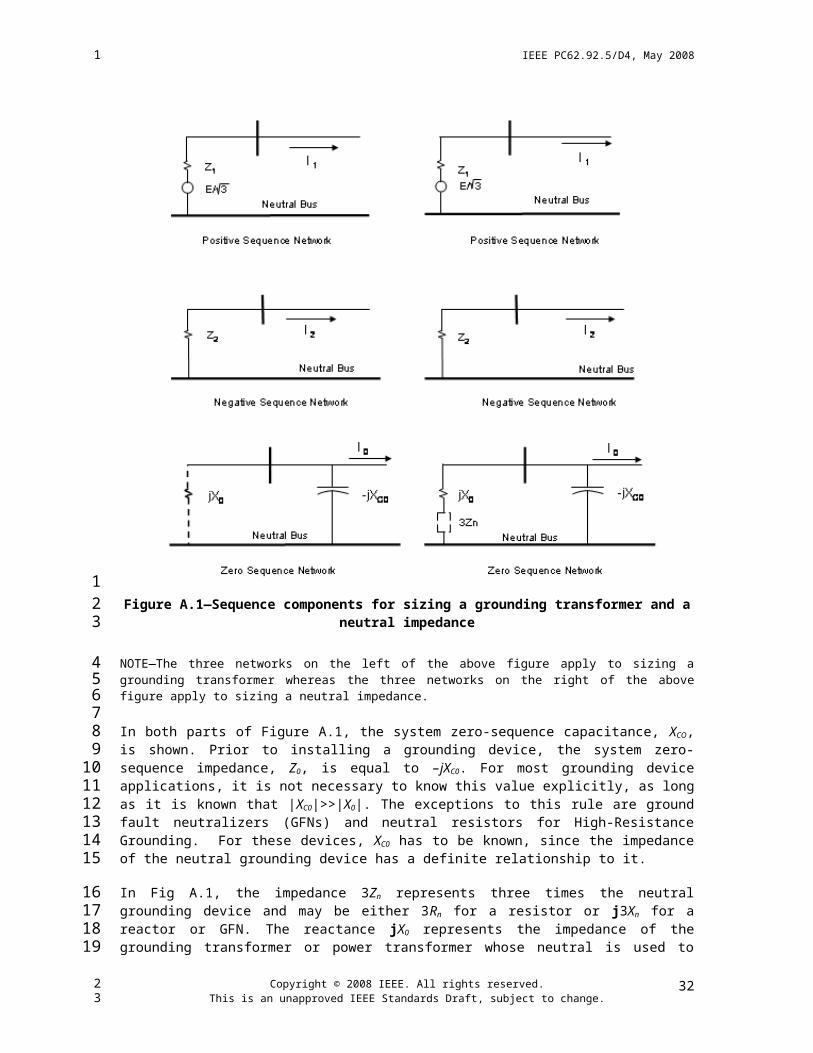
IEEE PC62.92.5/D4, May 2008
Annex C
(informative)
Bibliography
C.1 General
[B1] AIEE Committee Report, “Application Guide for Ground-Fault Neutralizers,” AIEE Transactions, pt. III, pp. 182–190, April 1953.
[B2] AIEE Committee Report, “Application Guide on Methods of Neutral Grounding of Transmission Systems,” AIEE Transactions on Power Apparatus and Systems, vol. 72, pt. III, pp. 663-668, August, 1953 (AIEE 954 October 1954).
[B3] AIEE Committee Report, “Report on Survey of Unbalanced Charging Currents on Transmission Lines as Affecting Ground-Fault Neutralizers,” AIEE Transactions, vol. 60, pt. II, pp. 1328–1339, 1949.
[B4] Brown, H. H. and Gross, E. T. B., “Experience with Resonant Grounding in a Large 34.5 kV System,” IEEE Transactions, vol. PAS-85, no. 5., pp. 541–547, May 1966.
[B5] Central Stations Engineers of the Westinghouse Electric Corporation, Electrical Transmission and Distribution Reference Book, Chapter 19, Grounding of Power System Neutrals. Raleigh, NC: Asea Brown Boveri/Transmission Technology Institute, 1950.
[B6] Gross, E. T. B. and Atherton, E. W., “Application of Resonant Grounding in Power Systems in the United States,” AIEE Transactions, vol. 70, pp. 389–396, 1951.
[B7] IEEE Std. 80-2000, IEEE Guide for Safety in AC Substation Grounding (ANSI).
[B8] IEEE Std. 142-1991 (R1996), IEEE Recommended Practice for Grounding of Industrial and Com-mercial Power Systems (IEEE Green Book) (ANSI).
[B9] IEEE Std. C37.010-1999, IEEE Application Guide for AC High-Voltage Circuit Breakers Rated on a Symmetrical Current Basis (ANSI).
[B10] IEEE Std. C62.2-1987 (Withdrawn), IEEE Guide for the Application of Gapped Silicon-Carbide Surge Arresters for Alternating-Current (ANSI).
[B11] IEEE Std. C62.92.2-1989 (R2000), IEEE Guide for the Application of Neutral Grounding in Elec-trical Utility Systems, Part II—Grounding of Synchronous Generator Systems (ANSI).
[B12] IEEE Std. 100-2000, The Authoritative Dictionary of IEEE Standards Terms.
[B13] IEEE Tutorial Course, Surge Protection in Power Systems, Chapter 2, “Grounding Power System Neutrals,” 79EH0144-6PWR.
[B14] Project UHV and Transmission Engineers of General Electric, Transmission Line Reference Book, 345 kV and Above. Palo Alto, CA: Electric Power Research Institute, 1982.
[B15] Rudenberg, R., Transient Performance of Electric Power Systems. New York: McGraw-Hill Book Company, Inc., 1950.
Copyright © 2008 IEEE. All rights reserved.This is an unapproved IEEE Standards Draft, subject to change.
34
1
1
2
3
4
56
789
1011
1213
141516
1718
19
2021
2223
2425
2627
28
2930
3132
3334
23

IEEE PC62.92.5/D4, May 2008
[B16] Willheim, R. and Waters, M., Neutral Grounding in High-Voltage Transmission. New York: Elsevier Publishing Company, 1956.
C.2 Effect of system grounding on transient overvoltages
[B17] Allen, J. E. and Waldorf, S.K., “Arcing Ground Tests on a Normally Ungrounded 13-kV 3-Phase Bus,” AIEE Transactions, vol. 65, pp. 298-306, 1946.
[B18] Breuer, G. D., Johnson, I. B., and Lyon, S. V., “Grounding of Subtransmission Systems,” AIEE Transactions, vol. 73, pt. III-B, Power Apparatus and Systems, pp. 1580-1585, 1954.
[B19] Clarke, Edith, Crary, S. B., and Peterson, H. A., “Overvoltages During Power System Faults,” AIEE Transactions, vol. 58, pp. 377-385, 1939.
[B20] Concordia, C. and Peterson, H. A., “Arcing Faults in Power Systems,” AIEE Transactions, vol. 60, pp.340-346, 1941.
[B21] Concordia, C.and Skeats, W. F., “Effect of Restriking on Recovery Voltage,” AIEE Transactions, vol. 58, pp. 371-376, 1939.
[B22] Eaton, J. R., Peck, J. K., and Dunham, J. M., “Experimental Studies of Arcing Faults on a 75 kV Transmission System,” AIEE Transactions, vol. 50, no. 4, pp. 1669-1479, 1931.
[B23] Evans, R. D., Montieth, A. C., and Witzke, R. L., “Power System Transients Caused by Switching and Faults,” AIEE Transactions, vol. 58 pp. 386-397, 1939.
[B24] Gilkeson, C. L. and Jeanne, P. A., “Overvoltages on Transmission Lines,” AIEE Transactions, vol. 53, no. 5, pp. 1301-1309, 1934.
[B25] Peterson, Harold A., Transients in Power Systems, New York: John Wiley & Sons, Inc., 1951.
C.3 Neutral inversion and instability
[B26] Boyajian, A. and McCarthy, O. P., “Physical Nature of Neutral Instability,” AIEE Transactions, vol. 50, pp. 317-327, 1931.
[B27] Gleason, Lyle L., “Neutral Inversion of Single Potential Transformer Connected Line to Ground on an Isolated Delta System,” AIEE Transactions, vol. 70, pt. I, pp. 103-111, 1951.
[B28] Karlicek, R. F. and Taylor, E. R., Jr., “Ferroresonance of Grounded Potential Transformers on Ungrounded Power Systems,” AIEE Transactions, vol. 78 p. IIIA, Power Apparatus and Systems, pp. 607-614, 1959.
[B29] LaPierre, C. W., “Theory of Abnormal Line to Neutral Transformer Voltages,” AIEE Transactions, vol. 50, pp. 328-342, 1931.
[B30] Shott, H. S. and Peterson, H. A., “Criteria for Neutral Stability of Wye-Grounded-Primary Broken Delta-Secondary Transformer Circuits,” AIEE Transactions, vol. 60, pp. 997-1002, November 1941.
[B31] Weller, C. T., “Experiences with Grounded-Neutral, Y-Connected Potential Transformers on Ungrounded Systems,” AIEE Transactions, vol. 50, pp. 299-316, 1931.
Copyright © 2008 IEEE. All rights reserved.This is an unapproved IEEE Standards Draft, subject to change.
35
1
12
3
45
67
89
1011
1213
1415
1617
1819
20
21
2223
2425
262728
2930
3132
3334
23

IEEE PC62.92.5/D4, May 2008
C.4 Effects of equipment-neutral grounding
[B32] ANSI C37.06-2000, American National Standard for Switchgear – AC High-Voltage Circuit Breakers Rated on a Symmetrical Current Basis – Preferred Ratings and Related Required Capabilities.
[B33] Central Station Engineers of the Westinghouse Electric Corporation, Electrical Transmission and Distribution Reference Book, Chapter 23, Coordination of Power and Communication Systems, Raleigh, NC: Asea Brown Boveri/Transmission Technical Institute, 1950.
[B34] Fillenberg, R. R., Cleaveland, G. W., and Harris, R. E., “Exploration of Transients by Switching Capacitors,” IEEE Transactions on Power Apparatus and Systems, vol. PAS-90, no. 1, pp. 250-257, January/February 1971.
[B35] Harner R. E. and Owen R. E., “Neutral Displacement of Ungrounded Capacitor Banks During Switching,” IEEE Transactions on Power Apparatus and Systems, vol. PAS-90, pp. 1631-1638, July/August 1971.
[B36] Johnson, I.B., Schultz, A. J., Schultz, N. R., and Shores, R. B., “Some Fundamentals of Capacitive Switching,” AIEE Transactions, vol. 74, pt. III, Power Apparatus and Systems, pp. 727-736, 1955.
[B37] IEEE Std. C37.04-1999, IEEE Standard Rating Structure for AC High-Voltage Circuit Breakers Rated on a Symmetrical Current Basis – Preferred Ratings (ANSI)
[B38] IEEE Std. C37.012-1979 (R2000), IEEE Application Guide for Capacitance Current Switching for AC High-Voltage Circuit Breakers Rated on a Symmetrical Current Basis (ANSI).
[B39] IEEE C37.99-2000, IEEE Guide for Protection of Shunt Capacitor Banks.
[B40] Rogers, E. J. and Gillies, D. A., “Shunt Capacitor Switching EMI Voltages, Their Reduction in BPA Substations,” IEEE Transactions, vol. PAS-93, pt. III, Power Apparatus and Systems, pp. 1849-1860, November/December 1974.
[B41] Van Sickle, R. C. and Zaborsky, J., “Capacitor Switching Phenomenon,” AIEE Transactions, vol. 80, pp. 151-158, 1951.
[B42] Kimbark, E. W., “Bibliography on Single-Pole Switching,” IEEE Transactions on Power Apparatus and Systems, vol. PAS-75, pp. 1072-1078, May/June 1975.
[B43] Kimbark, E. W., “Suppression of Ground-Fault Arcs on Single-Pole-Switched EHV Lines by Shunt Reactors,” IEEE Transactions on Power Apparatus and Systems, vol. 83, pp. 285-290, March 1964.
[B44] Knudson, N., “Single-Phase Switching of Transmission Lines Using Reactors for Extinction of the Secondary Arc,” CIGRE Report No. 10, 1962 Session.
[B45] Sekine, Y. et al., “Asymmetrical Four-Legged Reactor Extinguishing Secondary Arc Current for High-Speed Reclosing on UHV System,” CIGRE Paper 38-03, 1984 Session.
[B46] Shperling, B. R., Fakheri, A., and Ware, B. J., “Compensation Scheme for Single-Pole Switching on Untransposed Transmission Lines,” IEEE Transactions on Power Apparatus and Systems, vol. PAS-97, pp. 1421-1429, July/August 1978.
Copyright © 2008 IEEE. All rights reserved.This is an unapproved IEEE Standards Draft, subject to change.
36
1
1
23
456
789
101112
1314
1516
1718
19
202122
2324
2526
2728
2930
3132
333435
23
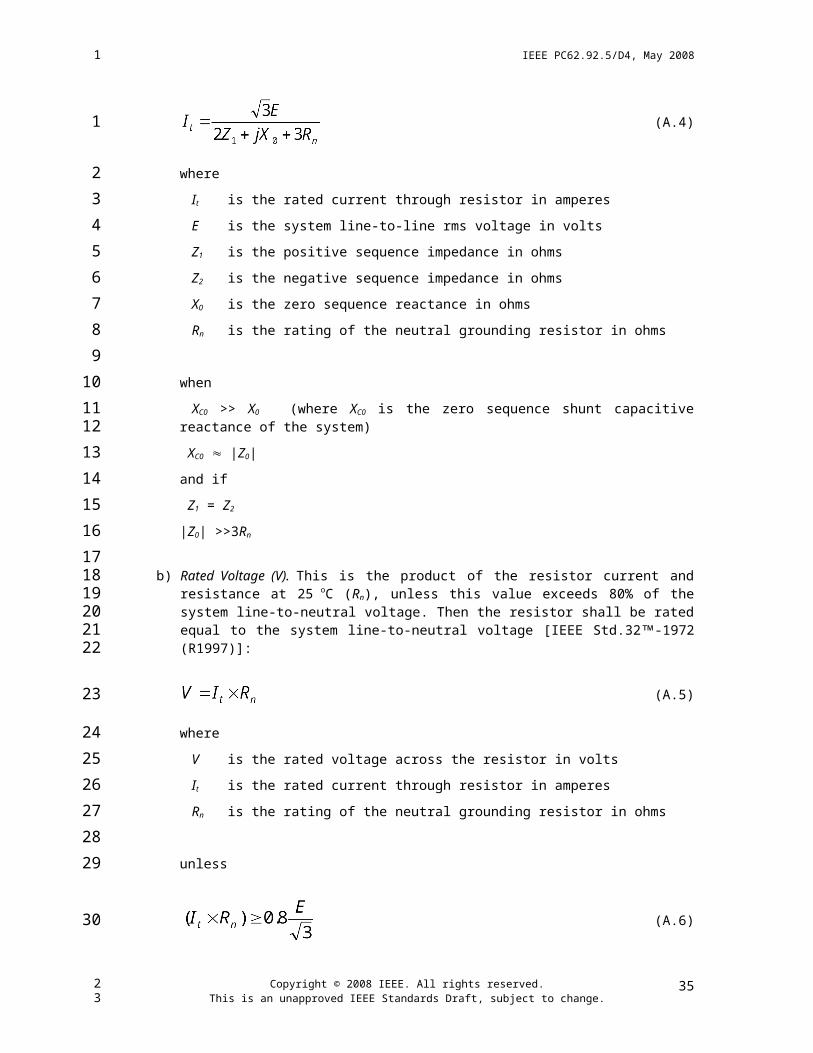
IEEE PC62.92.5/D4, May 2008
C.5 Series compensation of transmission lines
[B47] Allustriarti, R. et al., “Design and Uprating Performance of 500-kV Metal-Oxide-Protected Series-Capacitor Banks on the Table Mountain-Tesla Line,” IEEE Transactions on Power Delivery, vol. 3, no. 4, pp. 1951-1957, October 1988.
[B48] Barcus, J. M. et al., “The Varistor Protected Series Capacitor at the 500-kV Broadview Substation,” IEEE Transactions on Power Delivery, vol. 3, no. 4 pp. 1976-1985, October 1988.
[B49] Benko, I. S. et al., “Internal Overvoltages and Protective Devices in EHV Compensated Systems-Series Capacitors and Shunt Reactors,” CIGRE Paper 33-05, 1976 Session.
[B50] Butler, J. W. and Concordia, C., “Analysis of Series Capacitor Application Problems,” AIEE Transactions, vol. 56, pp. 975-988, August 1937.
[B51] Harder, E. L., Barkle, J. E., and Ferguson, R. W., “Series Capacitors During Faults and Reclosing,” AIEE Transactions, vol. 70, pp. 1627-1642, 1957.
[B52] IEEE Committee Report, “A Bibliography for Study of Subsynchronous Resonance Between Rotating Machines and Power Systems,” IEEE Transactions on Power Apparatus and Systems, vol. PAS-95, no. 1, pp. 216-218, January/February 1976. (See also later supplements to this bibliography)
[B53] Iliceto, F. et al., “Transient Voltages and Currents in Series-Compensated EHV Lines,” Proceedings of the IEEE, vol. 123, no. 8, pp. 811-817, August 1976.
[B54] Maneatis, J. A. et al., “500-kV Series Capacitor Installations in California,” IEEE Transactions on Power Apparatus and Systems, vol. PAS-90, pp. 1138-1149, May/June 1978.
[B55] Niggli, M. R. et al., “Fault Clearing Overvoltages on Long Transformer Terminated Lines,” IEEE Transactions on Power Apparatus and Systems, vol. 93, pp. 667-678, March/April 1974.
[B56] Thanassoulis, P. et al, “Overvoltages on a Series-Compensated 750-kV System for the 10000 MW Itaipu Project,” IEEE Transactions on Power Apparatus and Systems, vol. PAS-94, pp. 622-631, March/April 1975.
[B57] Wilson, D. D., “Series Compensated Lines – Voltage Across Circuit Breakers and Terminals Caused by Switching,” IEEE Transactions on Power Apparatus and Systems, vol. PAS-92, pp. 1050-1056, May/June 1973.
Copyright © 2008 IEEE. All rights reserved.This is an unapproved IEEE Standards Draft, subject to change.
37
1
1
234
56
78
910
1112
131415
1617
1819
2021
222324
252627
28
29
23