Embed Size (px)
Citation preview
IEEE TRANSACTIONS ON COMPUTER AIDED DESIGN OF INTEGRATED CIRCUITS AND SYSTEMS, VOL. X, NO. X, XX 2016 1
Adaptive Tuning of Photonic Devices in a PhotonicNoC Through Dynamic Workload Allocation
Jose L. Abellan, Member, IEEE, Ayse K. Coskun, Member, IEEE, Anjun Gu, Student Member, IEEE, Warren Jin,Ajay Joshi, Member, IEEE, Andrew B. Kahng, Fellow, IEEE, Jonathan Klamkin, Senior Member, IEEE,
Cristian Morales, John Recchio, Student Member, IEEE, Vaishnav Srinivas, Member, IEEE,Tiansheng Zhang, Student Member, IEEE
Abstract—Photonic network-on-chip (PNoC) is a promisingcandidate to replace traditional electrical NoC (ENoC) in many-core systems that require substantial bandwidths. The photoniclinks in the PNoC comprise laser sources, optical ring resonators,passive waveguides, and photodetectors. Reliable link operationrequires laser sources and ring resonators to have matchingoptical frequencies. However, inherent thermal sensitivity ofphotonic devices and manufacturing process variations can leadto a frequency mismatch. To avoid this mismatch, micro-heatersare used for thermal trimming and tuning, which can dissipatea significant amount of power. This paper proposes a novelFreqAlign workload allocation policy, accompanying an AdaptiveFrequency Tuning (AFT) policy, that is capable of reducingthermal tuning power of PNoC. FreqAlign uses thread allocationand thread migration to control temperature for matching theoptical frequencies of ring resonators in each photonic link. TheAFT policy reduces the remaining optical frequency differenceamong ring resonators and corresponding on-chip laser sourcesby hardware tuning methods. We use a full modeling stack of aPNoC that includes a performance simulator, a power simulator,and a thermal simulator with a temperature-dependent lasersource power model to design and evaluate our proposed policies.Our experimental results demonstrate that FreqAlign reduces theresonant frequency gradient between ring resonators by 50-60%when compared to existing workload allocation policies. Coupledwith AFT, FreqAlign reduces localized thermal tuning power by19.28 W on average, and is capable of saving up to 34.57 Wwhen running realistic loads in a 256-core system without anyperformance degradation.
I. INTRODUCTION
As core count increases in manycore systems to supportthe ever-increasing thread-level parallelism exhibited by ap-
Manuscript received November 19, 2015; revised March 14, 2016 and June1, 2016; accepted July 24, 2016. Current version published XXX XX, 2016.This work was supported by the NSF grants CNS-1149703 and CCF-1149549.This paper was recommended by Associate Editor L. P. Carloni.
J. L. Abellan is with the Department of Computer Science, CatholicUniversity of Murcia, Murcia 30107, Spain.
A. K. Coskun, A. Joshi, C. Morales and T. Zhang are with the Departmentof Electrical and Computer Engineering, Boston University, Boston, MA02215 USA.
A. Gu, J. Recchio and V. Srinivas are with the Department of Electricaland Computer Engineering, University of California at San Diego, La Jolla,CA 92093 USA.
W. Jin and J. Klamkin are with the Department of Electrical and ComputerEngineering, University of California at Santa Barbara, Santa Barbara, CA93106 USA.
A. B. Kahng is with the Department of Computer Science and Engineeringand the Department of Electrical and Computer Engineering, University ofCalifornia at San Diego, La Jolla, CA 92093 USA.
plications, the NoC bandwidth must correspondingly increaseto maximize application performance. Future application do-mains (e.g., cyber-physical and big data) are expected to re-quire even larger network-on-chip (NoC) bandwidths. At suf-ficiently large bandwidths, photonic links can improve energy-per-bit performance over electrical links with their higherbandwidth density (Gbps/µm), lower global communicationlatency, and lower data-dependent power [1], [2], [3], [4], [5].
A typical silicon photonic link consists of: (1) a lasersource to emit optical waves, (2) a ring modulator and a ringfilter to modulate optical waves at the transmitter and filterthem at the receiver, respectively, (3) a passive waveguide topropagate optical waves, and (4) a photodetector to convertoptical signals into electrical signals. Silicon photonic linksrequire the optical frequency of the laser source powering thatlink to match with the resonant frequencies of its associatedring modulators and filters. In a photonic NoC (PNoC), thering resonators are typically placed close to the cores to reducethe delay and energy of the electrical link connecting thecores to the silicon photonic link transmitter and receiver, butresonant frequencies of these ring resonators are sensitive totemperature. Variations in core power consumption can alter aring’s temperature and introduce data transmission errors (i.e.,increasing the link error rates) or even break the link entirely.
In PNoC, thermal tuning via micro-heaters [6] is commonlyused to match the resonant frequencies of ring resonators, andthe frequencies of ring resonators with those of laser sources.However, this method induces significant power overheadwhen there are large optical frequency mismatches betweenring resonators and corresponding laser sources. Thus, lowoverhead tuning methods that can match the optical frequen-cies of both ring resonators and laser sources are required.On-chip laser sources are good candidates for reducing thermaltuning power due to their close proximity to the PNoC controlcircuits [7]. Their proximity allows for runtime control overtheir optical frequencies, which allows for more flexible tuningmethods for photonic devices to be implemented.1
In this paper we propose FreqAlign, a new workload al-location policy, and an Adaptive Frequency Tuning (AFT)policy, which work together to match the optical frequencies
1Using off-chip laser sources to power silicon photonic links is anotheroption, and may provide better temperature stability and higher operatingefficiency than on-chip laser sources. However, the lack of runtime controlmakes them less flexible for optical frequency tuning.
Copyright (c) 2016 IEEE. Personal use of this material is permitted. However, permission to use this materialfor any other purposes must be obtained from the IEEE by sending an email to [email protected].
IEEE TRANSACTIONS ON COMPUTER AIDED DESIGN OF INTEGRATED CIRCUITS AND SYSTEMS, VOL. X, NO. X, XX 2016 2
of the on-chip laser sources and ring resonators in a PNoCto minimize tuning power. FreqAlign first spatially assignsworkloads to cores in a manycore system to achieve an on-dietemperature gradient that minimizes the difference among theresonant frequencies of the ring resonators. AFT then locallytunes the temperatures of ring resonators and laser sourcesfor the remaining differences in their optical frequencies. Themain contributions of this paper are the following:• We provide a full modeling stack of performance, power and
thermal simulations for a manycore system with a PNoC, in-cluding a temperature-dependent laser source power model.
• We propose a novel workload allocation policy, FreqAlign,which performs significantly better than our previouslyproposed workload allocation policy, RingAware [8], inmatching the resonant frequencies of the ring resonators,even in the presence of process variations and for variousPNoC logical topology and physical layout combinations.
• We propose AFT, a tuning policy to control the opticalfrequencies of on-chip laser sources adaptively based onthe temperatures of ring resonators at runtime to reduce thetuning power of manycore systems with PNoC.
• We demonstrate that when running real workloads, Freq-Align reduces the resonant frequency difference betweenring resonators in the same photonic link by 50-60% com-pared to RingAware without any performance degradation.Proposed AFT reduces thermal tuning power by as much as34.57 W when compared to the baseline tuning policy.The rest of the paper starts with a review of related work in
Section II. Section III presents our target manycore systemand PNoC design flow, and we introduce our simulationinfrastructure in Section IV. Section V describes our proposedworkload allocation and tuning policy. Section VI providesexperimental evaluation and Section VII concludes the paper.
II. RELATED WORK
Silicon photonics is a promising technology to support theincreasing demand for energy-efficient and high-bandwidthon-chip communication in future manycore systems. Com-pared to an electrical NoC (ENoC), a PNoC can providehigher bandwidth density with lower data-dependent powerdissipation. Thus, designing an energy-efficient PNoC hasbeen widely explored [1], [2], [3], [4], [5].
A major challenge in designing an energy-efficient PNoCis the large thermal tuning power overhead, which adverselyaffects PNoC energy efficiency. Photonic devices such asring resonators and laser sources are sensitive to temperature.The optical frequencies of these components need to matchto ensure link signal integrity. There has been some effortat the technology level to counter this thermal challenge,including the introduction of negative thermo-optic coefficientmaterials to compensate for the positive thermo-optic coef-ficient of silicon [9]. However, the technology surroundingthese athermal devices is immature and demonstrates thermalinsensitivity over only a limited temperature range. Anothermethod incorporates a heater with a temperature sensor forlocalized thermal tuning of ring resonators [6]. Other hardwareimplementations of wavelength locking including balanced
homodyne locking [10] and programmable locking and routingusing a field programmable gate array (FPGA) [11] have beendemonstrated as well. From the chip stack design perspective,inserting an insulation layer between logic and photonic layerscan decouple temperatures of these layers [12].
To compensate for the tuning power overhead, one methodis to tune a group of ring resonators simultaneously instead oftraditional single ring tuning, at the cost of additional hard-ware support [13]. Our prior RingAware workload allocationpolicy [8] balances the temperature of the ring groups withoutusing extra hardware, but this policy does not consider theimpact of process variation on the ring resonators, nor does itattempt to match the optical frequencies of the laser sourcesand ring resonators. Aurora [14] leverages localized tuningand workload allocation techniques and embodies a cross-layer approach at the device, architecture and OS levels. Atthe device level, Aurora controls small temperature variationsby applying a bias current through the ring resonators [15].For larger temperature changes, packets are rerouted awayfrom hot regions, and dynamic voltage and frequency scaling(DVFS) is applied to reduce the temperature of hot areas. Atthe OS level, a job allocation policy prioritizes jobs to theouter cores of the chip.
A common drawback among all these techniques is thatthere is no focus on matching the optical frequencies betweenon-chip laser sources and ring resonators under varying systemutilizations. Moreover, prior methods do not account for theimpact of temporal temperature variations on the thermaltuning power. In our work, we propose FreqAlign, a dynamicworkload allocation policy combined with AFT policy, tomatch the resonant frequencies of the ring resonators with theoptical frequencies output by their associated laser sources.Compared to solely balancing ring temperatures, our policyrequires much lower thermal tuning power under various ringplacements, process variation scenarios, and system layouts.
III. MANYCORE SYSTEMS WITH PNOC
To design a manycore system with PNoC, the requirementsand constraints for both electronic components and photonicdevices must be considered. In this section, we introduce thearchitecture of our target manycore system and PNoC designflow. Table I shows the notations used in this work.
A. Manycore System Architecture
We use a 256-core system designed using a typical 22 nmSOI CMOS process, operating at 1 GHz with 0.9 V supplyvoltage. For each core, we use an architecture similar to theIA-32 core from Intel SCC [16]. Every core consists of a16 KB I/D L1 cache and a 256 KB private L2 cache. Wescale the core architecture to 22 nm, resulting in a singlecore area of 0.93 mm2 (including the L1 cache), and an L2cache area of 0.35 mm2. Our total chip area2 is 326.5 mm2.The average power consumption for each core is 1.17 W . Thesystem is organized into 64 equal tiles. In each tile, four cores
2There are commercial products with similar die size and power consump-tion, e.g., SPARC T4 processor [17].
IEEE TRANSACTIONS ON COMPUTER AIDED DESIGN OF INTEGRATED CIRCUITS AND SYSTEMS, VOL. X, NO. X, XX 2016 3
Ring Group
L2Core +
L1
(a) 256-core system with U-shape layout of PNoC.
(b) 256-core system withhorizontally shifted ring groups.
(c) 256-core system withvertically shifted ring groups.
Waveguides
y inputsfor inputstage router Clos Network
z-ary
On-ChipLaser Source
(d) 256-core system with W-shape physical layout.
(e) 256-core system with 1:4 chip aspectratio and chain-shape physical layout.
InputStage
MiddleStage
OutputStage
50µm300µm
Active Region Cross Section:
30nm 2µm
470nm 470nm 1µm
WG* Ring WG Next WG
1.5µm
PD*
*WG -- WaveguideRing -- Ring modulators/filters
50µm
100nmburied oxide layer
SiO2 SiO2
substrate190nm
PD -- Photodetector
5µm
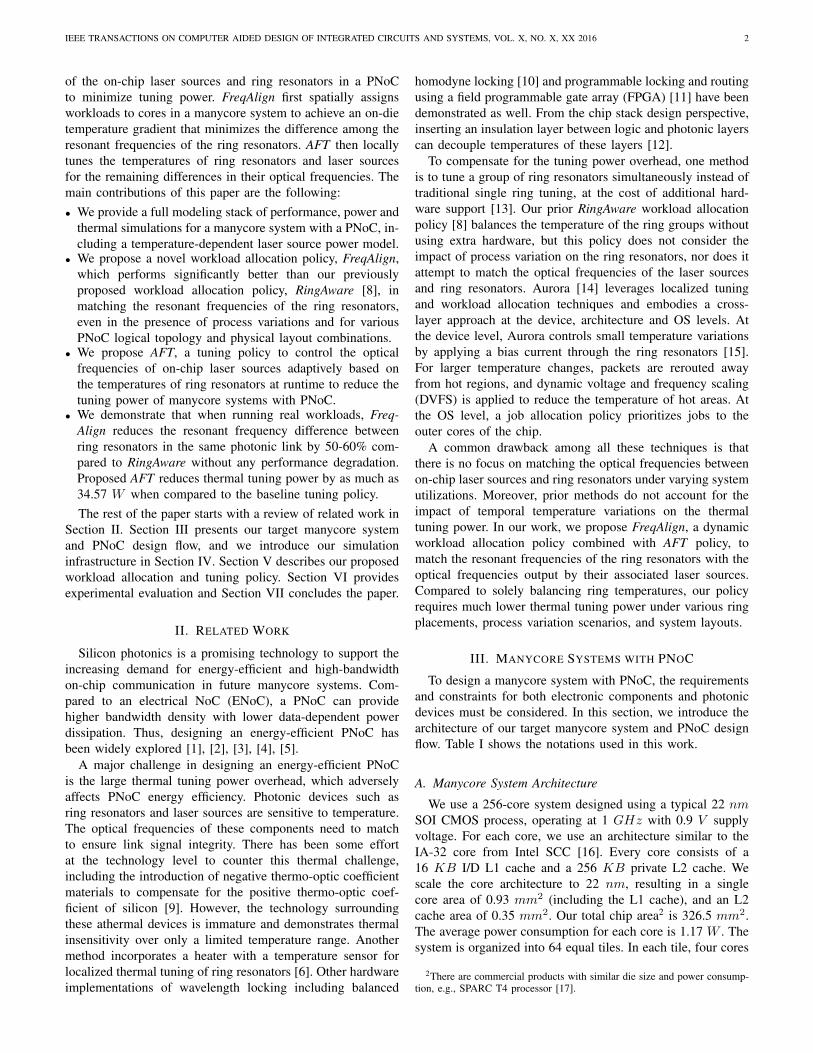
Fig. 1: Target manycore system with a PNoC (a), manycore systems with 8-ary 3-stage Clos topology and shifted physical layouts (b)-(c),and manycore systems with different logical topology and physical layout combinations (d)-(e). (d) is designed with 16-ary 3-stage Clostopology and W-shape physical layout; (e) is designed with 8-ary 3-stage Clos topology and chain-shape physical layout.
are connected via an electrical router. There are 16 memorycontrollers that are uniformly distributed along two edges ofthe chip. We use an 8-ary 3-stage Clos network topology toconnect the L2 caches and memory controllers. Our Clos canbe described by the triplet (x=8, y=10, z=8), where x is thenumber of middle stage routers, y is the number of I/O portson the first or last stage routers, and z is the number of firstor last stage routers. Therefore, the 8-ary 3-stage Clos PNoChas 128 channels in total.
We map the 8-ary 3-stage Clos topology to a U-shapedphysical layout of silicon photonic waveguides as shown inFigure 1(a), where each ring group is assigned to the nearesteight tiles and two memory controllers. We apply the siliconphotonic link technology described in prior work [18], [19],[20], where photonic devices are monolithically integratedwith CMOS devices. In this system, single crystal Si is utilizedfor waveguides and ring resonators, and Ge on Si is utilizedfor photodetectors. Ring resonators are designed in Si by ionimplantation and are tuned with metal heaters. We combinethe ring modulators and filters from one electrical router ofeach of the three network stages into a ring group (RG).The optical waves from laser sources arrive at a ring groupand are modulated. The modulated optical waves traverse thenetwork and are filtered by the ring filters in the destinationring group, where a photodetector converts the optical signalinto an electrical current that is fed to the link receiver circuit.Prior work [18], [19], [20] employs off-chip laser sources. Inthis work, we assume on-chip laser sources, which simplifypackaging, reduce cost and improve laser source control.Several approaches have been proposed for realizing on-chiplaser sources [22], [23], [24]. Specifically, our discussion
# of cores & NoC topology
Apps
BW per λ
BW requirement
# of λ
# of waveguides
# of λ per waveguide
RadiusRing design
Thermal
Spacing between λ
Resonant Frequency
Free Spetral Range
Optical NoC
Mismatch Impact
sensitivityng
needed area constraint
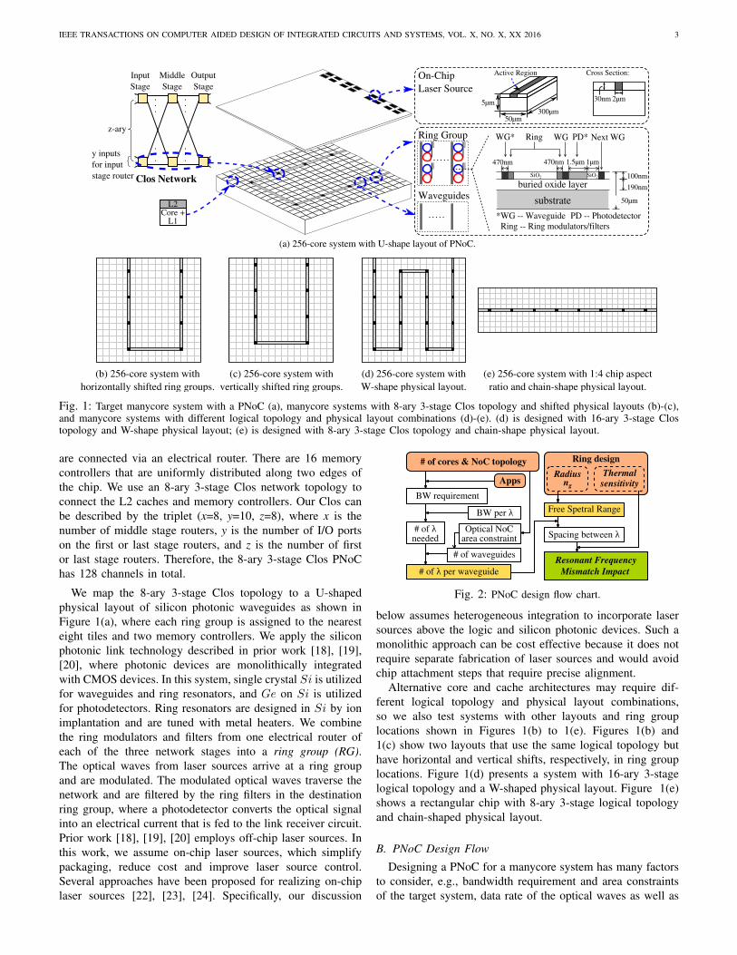
Fig. 2: PNoC design flow chart.
below assumes heterogeneous integration to incorporate lasersources above the logic and silicon photonic devices. Such amonolithic approach can be cost effective because it does notrequire separate fabrication of laser sources and would avoidchip attachment steps that require precise alignment.
Alternative core and cache architectures may require dif-ferent logical topology and physical layout combinations,so we also test systems with other layouts and ring grouplocations shown in Figures 1(b) to 1(e). Figures 1(b) and1(c) show two layouts that use the same logical topology buthave horizontal and vertical shifts, respectively, in ring grouplocations. Figure 1(d) presents a system with 16-ary 3-stagelogical topology and a W-shaped physical layout. Figure 1(e)shows a rectangular chip with 8-ary 3-stage logical topologyand chain-shaped physical layout.
B. PNoC Design Flow
Designing a PNoC for a manycore system has many factorsto consider, e.g., bandwidth requirement and area constraintsof the target system, data rate of the optical waves as well as

IEEE TRANSACTIONS ON COMPUTER AIDED DESIGN OF INTEGRATED CIRCUITS AND SYSTEMS, VOL. X, NO. X, XX 2016 4
TABLE I: Notations used in the paper.
Variable Definition Uniti Ring group indexj Core indexk Thread indexl Laser source indexs Simulation step indexg Material indexR Thermal resistivity m ·K/W
Rjoint Thermal resistivity of the NoC block m ·K/W
∆fR/∆fLSThermal sensitivity of ring resonators/ laser sources in frequency domain GHz/K
∆λR/∆λLSThermal sensitivity of ring resonators/ laser sources in wavelength domain pm/K
ηR/ηLSThermal tuning efficiency of ring
resonators / laser sources W/K
ngRefractive index of the ring resonator
materialr Ring resonator radius µm
V Volume m3
M Total number of ring groupsH Total number of rings in a ring groupN Total number of coresS Total number of threadsQ Total number of laser sources
nλNumber of wavelengths per
waveguidex Number of middle stage routers
yNumber of I/O ports on first or last
stage routersz Number of first or last stage routersw Weight factor K/W
wijWeight factor for ring group i and
core j for temperature impact K/W
∆w Weight factor difference K/Wt Time msT Temperature oC
TRGi Temperature of ring group i oCTLSl Temperature of laser source l oCPj Power of core j WPFT Optical frequency tuning power WPleak Leakage power Wλ Wavelength nmF Frequency GHz
FRGi Frequency of ring group i GHzFLSl Frequency of laser source l GHz
the design of ring resonators. To investigate the design spaceof a PNoC, we adopt a cross-layer approach where we jointlyconsider the photonic device design and NoC architecturedesign. Figure 2 shows the design flow adopted for jointlychoosing the ring dimensions, the number of wavelengths perwaveguide, and the number of waveguides for a given thermalgradient and area constraint. We consider area overhead as aconstraint in the design flow because monolithic integrationincreases die area, resulting in increased manufacturing cost.
The bandwidth requirement of a PNoC depends on targetedapplications in a manycore system. In this work, we simulateselected SPLASH-2 [25], PARSEC [26] and UHPC [27]applications on our manycore system and determine the peakNoC bandwidth (BW) requirement to be 512 GB/s, whichcorresponds to 64 bits/cycle for each photonic channel inour 8-ary 3-stage Clos network. A monolithically integratedsilicon photonic link with 2.5 Gbps/λ bandwidth has beendemonstrated in prior work [19]. In this work, we assume abandwidth of 4 Gbps/λ. This is reasonable considering theperformance of current silicon photonic devices that operatebeyond 25 Gbps [28]. The link bandwidth and the requiredbandwidth of the applications define the total number ofwavelengths needed in the PNoC. We constrain PNoC area tobe at most 10% of the total die area. This constraint puts an
f0 fnλ-1
Free Spectal Range (FSR)
FWHM
'f0f1 f2
RingModulatorSide
RingFilterSide
Case 1 Case 2
ΔF1 ΔF2
Fig. 3: Impact of resonant frequency mismatch. Case 1: Smallmismatch reduces the filtered optical power; Case 2: Large mismatchmay result in a ring to filter the data of its neighboring ring in thefrequency domain.
upper limit on the number of waveguides in the system andthus a lower limit on the number of wavelengths that needto be mapped to a waveguide. We ignore the non-linearitylimit on the power that can be injected into a waveguide [2].However, our proposed policy is applicable even if we accountfor waveguide non-linearity while designing a PNoC.
For the ring resonator design, we choose 10 µm as theradius. The ring resonators are designed around a centerwavelength (λ0) of 1550 nm and have a thermal sensitivity(∆λR) of 78 pm/K [18], which translates to a 9.7 GHz/Kfrequency shift (∆fR) based on the following equations:
F0 =c
λ0= 193 THz, (1)
∆λRλ0
=∆fRF0
(2)
This means that for every degree of temperature gradientbetween a ring modulator and ring filter in a link, there isa 9.7 GHz mismatch in resonant frequency.
The spacing between adjacent wavelengths depends on thefree spectral range (FSR) of a ring resonator design and thenumber of wavelengths per waveguide (nλ), as shown inEquations (3) and (4):
FSR =c
2πrng(3)
Fspacing =FSR
nλ(4)
where ng is the group index, c is the speed of light, andFspacing is the spacing in resonant frequency for two adjacentwavelengths in a waveguide. The impact of resonant frequencymismatch is shown in Figure 3, where FWHM represents fullwidth at half maximum. When the mismatch is small, a ringfilter receives only a portion of the signal power, resulting inless current from the photodetector and causing data loss (Case1). As the mismatch increases, a ring filter may even filterthe optical waves corresponding to its neighboring resonantfrequency (Case 2).
Within each ring group in a PNoC, there are ring resonatorswith varying resonant frequencies belonging to different sili-con photonic links. Each silicon photonic link is multiplexedwith other links on a waveguide and has one ring modulator(on the transmitter side) in one ring group and a ring filter(on the receiver side) with the same resonant frequency inanother ring group. For the sake of convenience, in the
IEEE TRANSACTIONS ON COMPUTER AIDED DESIGN OF INTEGRATED CIRCUITS AND SYSTEMS, VOL. X, NO. X, XX 2016 5
McPAT HotSpot
Workload Alloc. Policy
SniperCACTI
Perf.Stats
Power Traces
Leakage Power Model
Laser SourcePower Model
Arr.Time
JobName
ThreadCount
Job Queue
10 barnes 32
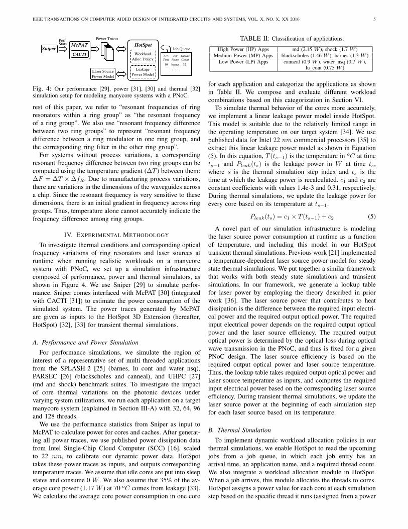
Fig. 4: Our performance [29], power [31], [30] and thermal [32]simulation setup for modeling manycore systems with a PNoC.
rest of this paper, we refer to “resonant frequencies of ringresonators within a ring group” as “the resonant frequencyof a ring group”. We also use “resonant frequency differencebetween two ring groups” to represent “resonant frequencydifference between a ring modulator in one ring group, andthe corresponding ring filter in the other ring group”.
For systems without process variations, a correspondingresonant frequency difference between two ring groups can becomputed using the temperature gradient (∆T ) between them:∆F = ∆T ×∆fR. Due to manufacturing process variations,there are variations in the dimensions of the waveguides acrossa chip. Since the resonant frequency is very sensitive to thesedimensions, there is an initial gradient in frequency across ringgroups. Thus, temperature alone cannot accurately indicate thefrequency difference among ring groups.
IV. EXPERIMENTAL METHODOLOGY
To investigate thermal conditions and corresponding opticalfrequency variations of ring resonators and laser sources atruntime when running realistic workloads on a manycoresystem with PNoC, we set up a simulation infrastructurecomposed of performance, power and thermal simulators, asshown in Figure 4. We use Sniper [29] to simulate perfor-mance. Sniper comes interfaced with McPAT [30] (integratedwith CACTI [31]) to estimate the power consumption of thesimulated system. The power traces generated by McPATare given as inputs to the HotSpot 3D Extension (hereafter,HotSpot) [32], [33] for transient thermal simulations.
A. Performance and Power Simulation
For performance simulations, we simulate the region ofinterest of a representative set of multi-threaded applicationsfrom the SPLASH-2 [25] (barnes, lu cont and water nsq),PARSEC [26] (blackscholes and canneal), and UHPC [27](md and shock) benchmark suites. To investigate the impactof core thermal variations on the photonic devices undervarying system utilizations, we run each application on a targetmanycore system (explained in Section III-A) with 32, 64, 96and 128 threads.
We use the performance statistics from Sniper as input toMcPAT to calculate power for cores and caches. After generat-ing all power traces, we use published power dissipation datafrom Intel Single-Chip Cloud Computer (SCC) [16], scaledto 22 nm, to calibrate our dynamic power data. HotSpottakes these power traces as inputs, and outputs correspondingtemperature traces. We assume that idle cores are put into sleepstates and consume 0 W . We also assume that 35% of the av-erage core power (1.17 W ) at 70 oC comes from leakage [33].We calculate the average core power consumption in one core
TABLE II: Classification of applications.
High Power (HP) Apps md (2.15 W ), shock (1.7 W )Medium Power (MP) Apps blackscholes (1.46 W ), barnes (1.3 W )
Low Power (LP) Apps canneal (0.9 W ), water nsq (0.7 W ),lu cont (0.75 W )
for each application and categorize the applications as shownin Table II. We compose and evaluate different workloadcombinations based on this categorization in Section VI.
To simulate thermal behavior of the cores more accurately,we implement a linear leakage power model inside HotSpot.This model is suitable due to the relatively limited range inthe operating temperature on our target system [34]. We usepublished data for Intel 22 nm commercial processors [35] toextract this linear leakage power model as shown in Equation(5). In this equation, T (ts−1) is the temperature in oC at timets−1 and Pleak(ts) is the leakage power in W at time ts,where s is the thermal simulation step index and ts is thetime at which the leakage power is recalculated. c1 and c2 areconstant coefficients with values 1.4e-3 and 0.31, respectively.During thermal simulations, we update the leakage power forevery core based on its temperature at ts−1.
Pleak(ts) = c1 × T (ts−1) + c2 (5)
A novel part of our simulation infrastructure is modelingthe laser source power consumption at runtime as a functionof temperature, and including this model in our HotSpottransient thermal simulations. Previous work [21] implementeda temperature-dependent laser source power model for steadystate thermal simulations. We put together a similar frameworkthat works with both steady state simulations and transientsimulations. In our framework, we generate a lookup tablefor laser power by employing the theory described in priorwork [36]. The laser source power that contributes to heatdissipation is the difference between the required input electri-cal power and the required output optical power. The requiredinput electrical power depends on the required output opticalpower and the laser source efficiency. The required outputoptical power is determined by the optical loss during opticalwave transmission in the PNoC, and thus is fixed for a givenPNoC design. The laser source efficiency is based on therequired output optical power and laser source temperature.Thus, the lookup table takes required output optical power andlaser source temperature as inputs, and computes the requiredinput electrical power based on the corresponding laser sourceefficiency. During transient thermal simulations, we update thelaser source power at the beginning of each simulation stepfor each laser source based on its temperature.
B. Thermal Simulation
To implement dynamic workload allocation policies in ourthermal simulations, we enable HotSpot to read the upcomingjobs from a job queue, in which each job entry has anarrival time, an application name, and a required thread count.We also integrate a workload allocation module in HotSpot.When a job arrives, this module allocates the threads to cores.HotSpot assigns a power value for each core at each simulationstep based on the specific thread it runs (assigned from a power
IEEE TRANSACTIONS ON COMPUTER AIDED DESIGN OF INTEGRATED CIRCUITS AND SYSTEMS, VOL. X, NO. X, XX 2016 6
WorkloadDistribution
Core & CachePower
Ring GroupTemperature
Laser SourceTemperature
Laser & RingControl Power
Core & CacheTemperature
Ring GroupProcess Variation
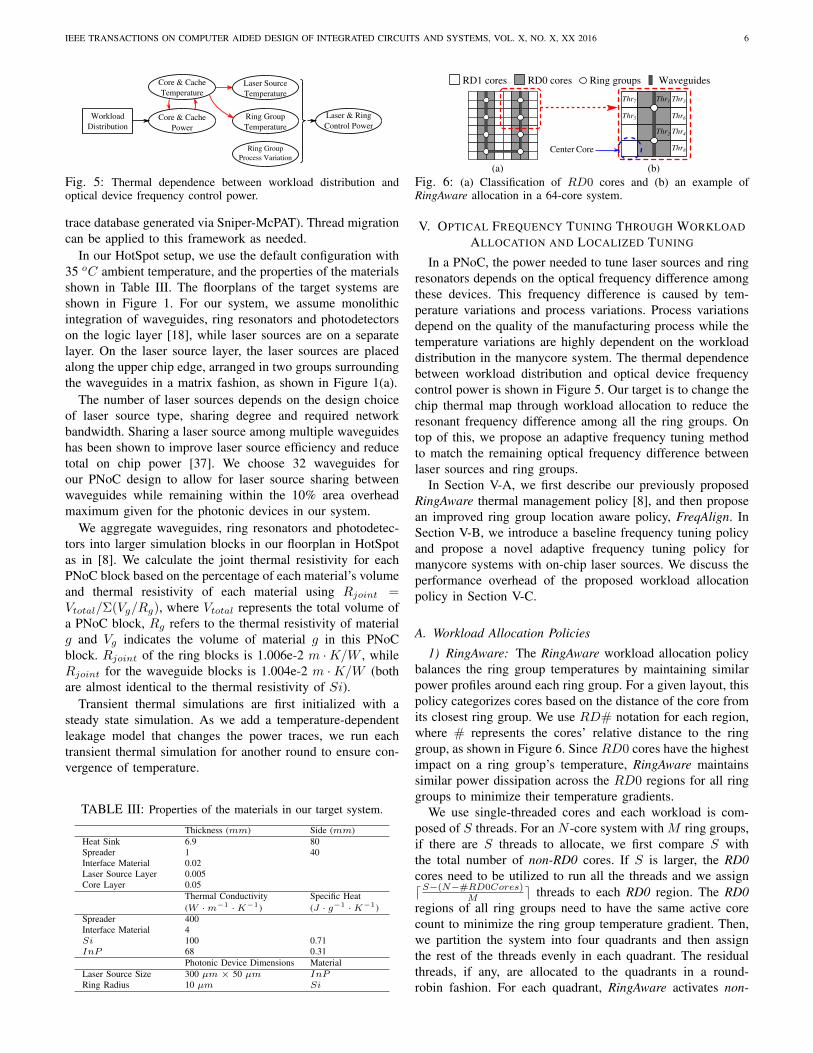
Fig. 5: Thermal dependence between workload distribution andoptical device frequency control power.
trace database generated via Sniper-McPAT). Thread migrationcan be applied to this framework as needed.
In our HotSpot setup, we use the default configuration with35 oC ambient temperature, and the properties of the materialsshown in Table III. The floorplans of the target systems areshown in Figure 1. For our system, we assume monolithicintegration of waveguides, ring resonators and photodetectorson the logic layer [18], while laser sources are on a separatelayer. On the laser source layer, the laser sources are placedalong the upper chip edge, arranged in two groups surroundingthe waveguides in a matrix fashion, as shown in Figure 1(a).
The number of laser sources depends on the design choiceof laser source type, sharing degree and required networkbandwidth. Sharing a laser source among multiple waveguideshas been shown to improve laser source efficiency and reducetotal on chip power [37]. We choose 32 waveguides forour PNoC design to allow for laser source sharing betweenwaveguides while remaining within the 10% area overheadmaximum given for the photonic devices in our system.
We aggregate waveguides, ring resonators and photodetec-tors into larger simulation blocks in our floorplan in HotSpotas in [8]. We calculate the joint thermal resistivity for eachPNoC block based on the percentage of each material’s volumeand thermal resistivity of each material using Rjoint =Vtotal/Σ(Vg/Rg), where Vtotal represents the total volume ofa PNoC block, Rg refers to the thermal resistivity of materialg and Vg indicates the volume of material g in this PNoCblock. Rjoint of the ring blocks is 1.006e-2 m ·K/W , whileRjoint for the waveguide blocks is 1.004e-2 m ·K/W (bothare almost identical to the thermal resistivity of Si).
Transient thermal simulations are first initialized with asteady state simulation. As we add a temperature-dependentleakage model that changes the power traces, we run eachtransient thermal simulation for another round to ensure con-vergence of temperature.
TABLE III: Properties of the materials in our target system.
Thickness (mm) Side (mm)Heat Sink 6.9 80Spreader 1 40Interface Material 0.02Laser Source Layer 0.005Core Layer 0.05
Thermal Conductivity Specific Heat(W ·m−1 ·K−1) (J · g−1 ·K−1)
Spreader 400Interface Material 4Si 100 0.71InP 68 0.31
Photonic Device Dimensions MaterialLaser Source Size 300 µm × 50 µm InPRing Radius 10 µm Si
RD0 cores Ring groups
Thr7
CoreCenter
(a) (b)
RD1 cores Waveguides
Thr5 Thr6
Thr3
Thr4
Thr8
Thr1
Thr2
Fig. 6: (a) Classification of RD0 cores and (b) an example ofRingAware allocation in a 64-core system.
V. OPTICAL FREQUENCY TUNING THROUGH WORKLOADALLOCATION AND LOCALIZED TUNING
In a PNoC, the power needed to tune laser sources and ringresonators depends on the optical frequency difference amongthese devices. This frequency difference is caused by tem-perature variations and process variations. Process variationsdepend on the quality of the manufacturing process while thetemperature variations are highly dependent on the workloaddistribution in the manycore system. The thermal dependencebetween workload distribution and optical device frequencycontrol power is shown in Figure 5. Our target is to change thechip thermal map through workload allocation to reduce theresonant frequency difference among all the ring groups. Ontop of this, we propose an adaptive frequency tuning methodto match the remaining optical frequency difference betweenlaser sources and ring groups.
In Section V-A, we first describe our previously proposedRingAware thermal management policy [8], and then proposean improved ring group location aware policy, FreqAlign. InSection V-B, we introduce a baseline frequency tuning policyand propose a novel adaptive frequency tuning policy formanycore systems with on-chip laser sources. We discuss theperformance overhead of the proposed workload allocationpolicy in Section V-C.
A. Workload Allocation Policies
1) RingAware: The RingAware workload allocation policybalances the ring group temperatures by maintaining similarpower profiles around each ring group. For a given layout, thispolicy categorizes cores based on the distance of the core fromits closest ring group. We use RD# notation for each region,where # represents the cores’ relative distance to the ringgroup, as shown in Figure 6. Since RD0 cores have the highestimpact on a ring group’s temperature, RingAware maintainssimilar power dissipation across the RD0 regions for all ringgroups to minimize their temperature gradients.
We use single-threaded cores and each workload is com-posed of S threads. For an N -core system with M ring groups,if there are S threads to allocate, we first compare S withthe total number of non-RD0 cores. If S is larger, the RD0cores need to be utilized to run all the threads and we assigndS−(N−#RD0Cores)
M e threads to each RD0 region. The RD0regions of all ring groups need to have the same active corecount to minimize the ring group temperature gradient. Then,we partition the system into four quadrants and then assignthe rest of the threads evenly in each quadrant. The residualthreads, if any, are allocated to the quadrants in a round-robin fashion. For each quadrant, RingAware activates non-
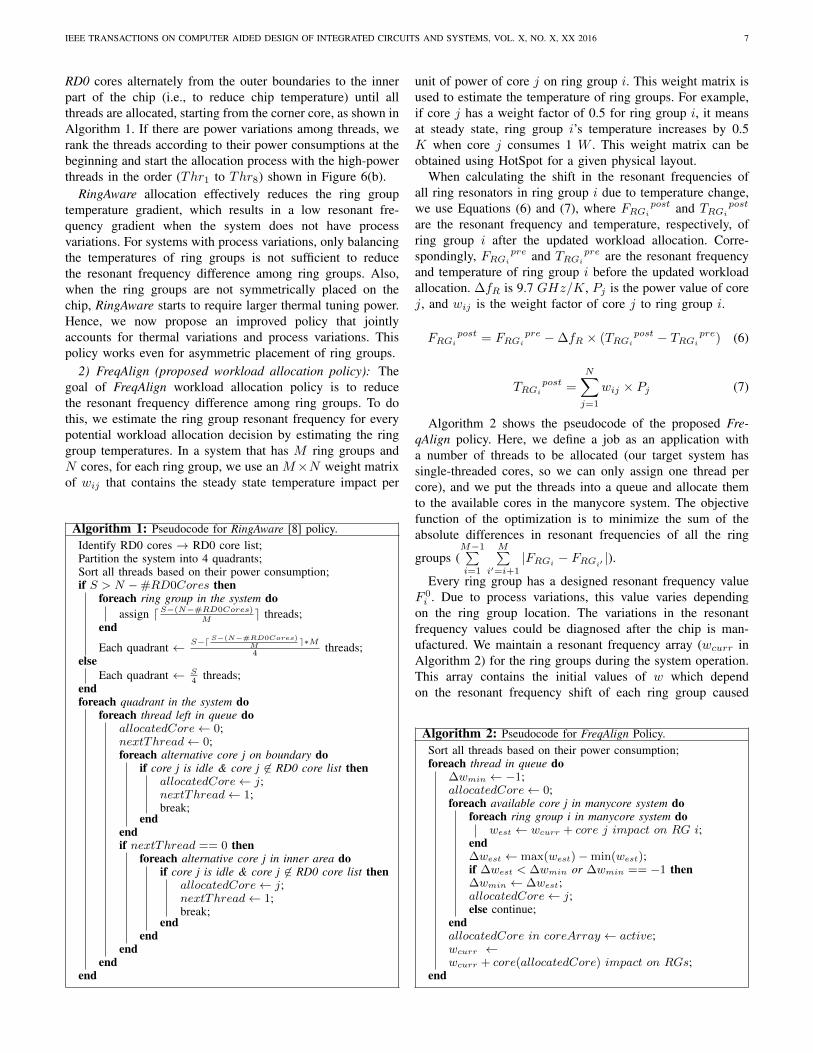
IEEE TRANSACTIONS ON COMPUTER AIDED DESIGN OF INTEGRATED CIRCUITS AND SYSTEMS, VOL. X, NO. X, XX 2016 7
RD0 cores alternately from the outer boundaries to the innerpart of the chip (i.e., to reduce chip temperature) until allthreads are allocated, starting from the corner core, as shown inAlgorithm 1. If there are power variations among threads, werank the threads according to their power consumptions at thebeginning and start the allocation process with the high-powerthreads in the order (Thr1 to Thr8) shown in Figure 6(b).
RingAware allocation effectively reduces the ring grouptemperature gradient, which results in a low resonant fre-quency gradient when the system does not have processvariations. For systems with process variations, only balancingthe temperatures of ring groups is not sufficient to reducethe resonant frequency difference among ring groups. Also,when the ring groups are not symmetrically placed on thechip, RingAware starts to require larger thermal tuning power.Hence, we now propose an improved policy that jointlyaccounts for thermal variations and process variations. Thispolicy works even for asymmetric placement of ring groups.
2) FreqAlign (proposed workload allocation policy): Thegoal of FreqAlign workload allocation policy is to reducethe resonant frequency difference among ring groups. To dothis, we estimate the ring group resonant frequency for everypotential workload allocation decision by estimating the ringgroup temperatures. In a system that has M ring groups andN cores, for each ring group, we use an M×N weight matrixof wij that contains the steady state temperature impact per
Algorithm 1: Pseudocode for RingAware [8] policy.Identify RD0 cores → RD0 core list;Partition the system into 4 quadrants;Sort all threads based on their power consumption;if S > N −#RD0Cores then
foreach ring group in the system doassign dS−(N−#RD0Cores)
Me threads;
end
Each quadrant ← S−dS−(N−#RD0Cores)M
e∗M4
threads;else
Each quadrant ← S4
threads;endforeach quadrant in the system do
foreach thread left in queue doallocatedCore← 0;nextThread← 0;foreach alternative core j on boundary do
if core j is idle & core j 6∈ RD0 core list thenallocatedCore← j;nextThread← 1;break;
endendif nextThread == 0 then
foreach alternative core j in inner area doif core j is idle & core j 6∈ RD0 core list then
allocatedCore← j;nextThread← 1;break;
endend
endend
end
unit of power of core j on ring group i. This weight matrix isused to estimate the temperature of ring groups. For example,if core j has a weight factor of 0.5 for ring group i, it meansat steady state, ring group i’s temperature increases by 0.5K when core j consumes 1 W . This weight matrix can beobtained using HotSpot for a given physical layout.
When calculating the shift in the resonant frequencies ofall ring resonators in ring group i due to temperature change,we use Equations (6) and (7), where FRGi
post and TRGipost
are the resonant frequency and temperature, respectively, ofring group i after the updated workload allocation. Corre-spondingly, FRGi
pre and TRGipre are the resonant frequency
and temperature of ring group i before the updated workloadallocation. ∆fR is 9.7 GHz/K, Pj is the power value of corej, and wij is the weight factor of core j to ring group i.
FRGipost = FRGi
pre −∆fR × (TRGipost − TRGi
pre) (6)
TRGipost =
N∑j=1
wij × Pj (7)
Algorithm 2 shows the pseudocode of the proposed Fre-qAlign policy. Here, we define a job as an application witha number of threads to be allocated (our target system hassingle-threaded cores, so we can only assign one thread percore), and we put the threads into a queue and allocate themto the available cores in the manycore system. The objectivefunction of the optimization is to minimize the sum of theabsolute differences in resonant frequencies of all the ring
groups (M−1∑i=1
M∑i′=i+1
|FRGi − FRGi′ |).
Every ring group has a designed resonant frequency valueF 0i . Due to process variations, this value varies depending
on the ring group location. The variations in the resonantfrequency values could be diagnosed after the chip is man-ufactured. We maintain a resonant frequency array (wcurr inAlgorithm 2) for the ring groups during the system operation.This array contains the initial values of w which dependon the resonant frequency shift of each ring group caused
Algorithm 2: Pseudocode for FreqAlign Policy.Sort all threads based on their power consumption;foreach thread in queue do
∆wmin ← −1;allocatedCore← 0;foreach available core j in manycore system do
foreach ring group i in manycore system dowest ← wcurr + core j impact on RG i;
end∆west ← max(west)−min(west);if ∆west < ∆wmin or ∆wmin == −1 then∆wmin ← ∆west;allocatedCore← j;else continue;
endallocatedCore in coreArray ← active;wcurr ←wcurr + core(allocatedCore) impact on RGs;
end
IEEE TRANSACTIONS ON COMPUTER AIDED DESIGN OF INTEGRATED CIRCUITS AND SYSTEMS, VOL. X, NO. X, XX 2016 8
by its process variations. For example, an initial array of[5, 0, 0, 0, 0, 0, 0,−5], means that RG1 has a resonant fre-quency 5 K × 9.7 GHz/K = 48.5 GHz lower than thedesigned frequency while RG8 has a resonant frequency 48.5GHz higher than the designed frequency. Every time a coreis activated, we update this array based on the impact of thecore on these ring groups. Our target in workload allocationis to equalize the values in this array.
During the system operation, when an application with Sthreads arrives, we rank the threads based on their powerconsumption (which can be estimated through previous runsor performance counters history) and assign them to the coreswhile balancing the resonant frequency of the ring groups.After all S threads are allocated to the corresponding cores, thesystem starts to run. As Algorithm 2 shows, when assigningthe threads, we go through all the available cores in thesystem. For each available core, we calculate the expectedresonant frequency difference among all ring groups if athread is assigned to that core. For each thread, we select thecore that results in the smallest resonant frequency variationamong all ring groups (∆wmin). After assigning a thread, weupdate the estimated resonant frequency values for all ringgroups. We iterate this process until all threads are assigned.If there are jobs currently running on the manycore systemand a new job arrives, we rank the new threads and theexisting threads together according to their power consumptionand redo the workload allocation. The potential workloadmigration when redoing the allocation induces context switchoverhead and cache cold start effect to the system. FreqAligncan be integrated with the operating system scheduler andrun on any available core in the system. We discuss theperformance overhead of FreqAlign in Section V-C.
B. Frequency Tuning Methods
1) Baseline Frequency Tuning: Workload allocation canhelp decrease the resonant frequency difference among thering groups. We use localized tuning to compensate for theremaining resonant frequency difference as well as the opticalfrequency difference between ring groups and laser sources.Resonant frequencies of ring resonators can be controlledthrough thermal tuning devices such as micro-heaters. Asfor on-chip laser sources, their optical frequencies can becontrolled in a number of ways, depending on the laser sourcetype. For example, multi-section distributed Bragg reflectorlaser sources comprise of wavelength tuning control elementssuch as mirrors and a phase section. The wavelengths ofdistributed feedback lasers, which we use in this work, arecontrolled by injecting current. More advanced laser sourceson silicon photonic platforms may comprise of extra ring filterswithin the laser cavity that can be also used for tuning.
Our baseline frequency tuning method is Target FrequencyTuning (TFT). In this tuning method, at any given time duringsystem operation, all ring groups and laser sources are firsttuned to their optical frequencies at the temperature thresholdof the target manycore system (90 oC in our case), andthen are individually tuned further to compensate for processvariations to match their optical frequencies. We also assume
that all the ring resonators within a ring group share the sametemperature. Since the material used for the laser sources andring resonators have different thermo-optic coefficients, theirrespective tuning efficiencies (8 mW/nm [38] for the lasersources and 2.6 mW/nm [18] for the ring resonators) alsodiffer. The temperature sensitivity values for laser sources andring resonators are 12.5 GHz/K [39] and 9.7 GHz/K [40],respectively. For a fixed target optical frequency, the amount offrequency tuning power (PFT ) required is shown in Equation(8), where FLSl is the frequency of laser source l, Ftargeti/lis the desired target optical frequency of a photonic devicei/l at the target temperature, ∆fLS is the thermal sensitivityof the laser source, ηLS is the tuning efficiency of the lasersources, FRGi is the frequency of ring group i, ∆fR is thethermal sensitivity of the ring resonators, ηR is the tuningefficiency of a single ring resonator, Q is the total number oflaser sources, M is the total number of ring groups, and H isthe number of ring resonators in a ring group.
PFT =
Q∑l=1
|FLSl − Ftargetl |∆fLS
× ηLS+
M∑i=1
FRGi − Ftargeti∆fR
× ηR ×H
(8)
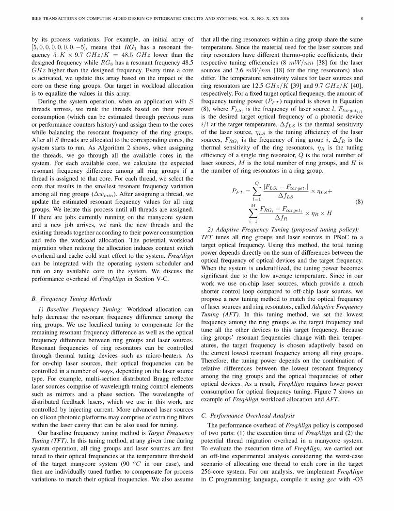
2) Adaptive Frequency Tuning (proposed tuning policy):TFT tunes all ring groups and laser sources in PNoC to atarget optical frequency. Using this method, the total tuningpower depends directly on the sum of differences between theoptical frequency of optical devices and the target frequency.When the system is underutilized, the tuning power becomessignificant due to the low average temperature. Since in ourwork we use on-chip laser sources, which provide a muchshorter control loop compared to off-chip laser sources, wepropose a new tuning method to match the optical frequencyof laser sources and ring resonators, called Adaptive FrequencyTuning (AFT). In this tuning method, we set the lowestfrequency among the ring groups as the target frequency andtune all the other devices to this target frequency. Becausering groups’ resonant frequencies change with their temper-atures, the target frequency is chosen adaptively based onthe current lowest resonant frequency among all ring groups.Therefore, the tuning power depends on the combination ofrelative differences between the lowest resonant frequencyamong the ring groups and the optical frequencies of otheroptical devices. As a result, FreqAlign requires lower powerconsumption for optical frequency tuning. Figure 7 shows anexample of FreqAlign workload allocation and AFT.
C. Performance Overhead Analysis
The performance overhead of FreqAlign policy is composedof two parts: (1) the execution time of FreqAlign and (2) thepotential thread migration overhead in a manycore system.To evaluate the execution time of FreqAlign, we carried outan off-line experimental analysis considering the worst-casescenario of allocating one thread to each core in the target256-core system. For our analysis, we implement FreqAlignin C programming language, compile it using gcc with -O3
IEEE TRANSACTIONS ON COMPUTER AIDED DESIGN OF INTEGRATED CIRCUITS AND SYSTEMS, VOL. X, NO. X, XX 2016 9
Ring Group 1
Ring Group 2
Ring Group 3
Optical Frequency
Designed optical freq.
Actual optical freq.(Process Variation)Optical freq. after each thread allocation
1
1
1234
4
4
3 2
3 2
Laser Source14 3 2
k Thread index
Optical freq. after tuning
Using tuning to adjust laser source's optical freq.
Fig. 7: Illustration of FreqAlign workload allocation policy andadaptive frequency tuning AFT policy. Every thread allocated byFreqAlign increases the temperatures of ring groups and causes adownward shift in their frequencies. When all threads are allocated,thermal tuning is used to bring all ring groups to the lowest commonresonant frequency. Above, ring groups 1 and 3, as well as the lasersource, are tuned to match the resonant frequency of ring group 2.
flag, and run it on Sniper. The simulation results show that theallocation of 256 threads to 256 cores takes a total of 192 µs.
Whenever a new job enters the system, thread allocation inFreqAlign also involves a reallocation process, in which wemigrate the existing threads if necessary. Thread migrationmay hurt application performance due to the context switchand the cache cold start effect. We use Sniper along withits hardware thread migration scheme [41] to investigate theimpact of thread migration overhead on our target system’sperformance. Once the pipeline of the core a thread is orig-inally running on has been drained, its architectural state istransferred to the destination core. The destination core thenstarts running the thread and endures the cache cold starteffect. The overhead from migrating a thread from one coreto another core includes three major components: (1) a fixedpenalty of 1000 cycles for storing and restoring the core’sarchitectural state [41]; (2) the time to drain the source core’spipeline prior to migration; and (3) the cache cold start effect.As quantified in several previous studies [41], [42], cache coldstart effect is the dominant component in migration overheadand can be two orders of magnitude larger than the other twocomponents combined. In our thread migration scheme, thereis no flushing of the source core’s caches. Every cache missin the destination core sends a memory request to the sourcecore’s L2 cache instead of memory. This lowers the numberof memory accesses. Any source core’s L2 cache block that isin shared/modified state triggers a writeback/invalidation usingthe normal cache coherency protocol.
As thread migration overhead varies with both applicationworkload and the number of threads needed to be migrated,we carry out a comprehensive experimental evaluation thatconsiders all applications under varying number of threadsused in this work (further details in Section VI). We configureSniper with multiple thread migration intervals (time sliceafter which a thread migrating process occurs): 500 µs, 1ms and 10 ms. For each interval case, we configure themigration percentage, i.e., the number of threads that actuallymigrate: 0.0 (baseline case without thread migration), 0.05 (5%
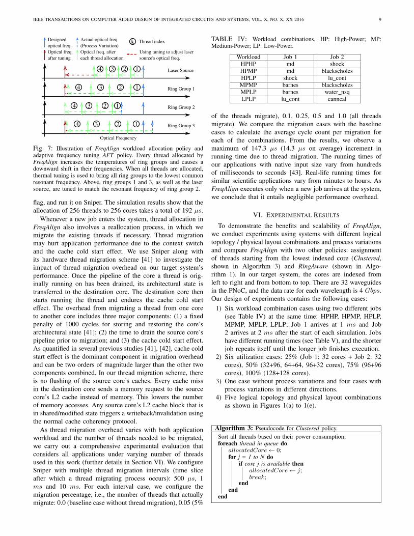
TABLE IV: Workload combinations. HP: High-Power; MP:Medium-Power; LP: Low-Power.
Workload Job 1 Job 2HPHP md shockHPMP md blackscholesHPLP shock lu contMPMP barnes blackscholesMPLP barnes water nsqLPLP lu cont canneal
of the threads migrate), 0.1, 0.25, 0.5 and 1.0 (all threadsmigrate). We compare the migration cases with the baselinecases to calculate the average cycle count per migration foreach of the combinations. From the results, we observe amaximum of 147.3 µs (14.3 µs on average) increment inrunning time due to thread migration. The running times ofour applications with native input size vary from hundredsof milliseconds to seconds [43]. Real-life running times forsimilar scientific applications vary from minutes to hours. AsFreqAlign executes only when a new job arrives at the system,we conclude that it entails negligible performance overhead.
VI. EXPERIMENTAL RESULTS
To demonstrate the benefits and scalability of FreqAlign,we conduct experiments using systems with different logicaltopology / physical layout combinations and process variationsand compare FreqAlign with two other policies: assignmentof threads starting from the lowest indexed core (Clustered,shown in Algorithm 3) and RingAware (shown in Algo-rithm 1). In our target system, the cores are indexed fromleft to right and from bottom to top. There are 32 waveguidesin the PNoC, and the data rate for each wavelength is 4 Gbps.Our design of experiments contains the following cases:
1) Six workload combination cases using two different jobs(see Table IV) at the same time: HPHP, HPMP, HPLP,MPMP, MPLP, LPLP; Job 1 arrives at 1 ms and Job2 arrives at 2 ms after the start of each simulation. Jobshave different running times (see Table V), and the shorterjob repeats itself until the longer job finishes execution.
2) Six utilization cases: 25% (Job 1: 32 cores + Job 2: 32cores), 50% (32+96, 64+64, 96+32 cores), 75% (96+96cores), 100% (128+128 cores).
3) One case without process variations and four cases withprocess variations in different directions.
4) Five logical topology and physical layout combinationsas shown in Figures 1(a) to 1(e).
Algorithm 3: Pseudocode for Clustered policy.Sort all threads based on their power consumption;foreach thread in queue do
allocatedCore← 0;for j = 1 to N do
if core j is available thenallocatedCore← j;break;
endend
end
IEEE TRANSACTIONS ON COMPUTER AIDED DESIGN OF INTEGRATED CIRCUITS AND SYSTEMS, VOL. X, NO. X, XX 2016 10
HPHP HPMP HPLP MPMP MPLP LPLP(a) Cluster Workload Allocation
0
20
40
60
80
100
120Re
sona
nce
Freq
uenc
y Di
ffere
nce
Amon
g Ri
ng G
roup
s (G
Hz)
32+32 64+64 32+96 96+32 96+96 128+128
HPHP HPMP HPLP MPMP MPLP LPLP(b) RingAware Workload Allocation
0
20
40
60
80
100
120
HPHP HPMP HPLP MPMP MPLP LPLP(c) FreqAlign Workload Allocation
0
20
40
60
80
100
120 HP: High PowerMP: Medium PowerLP: Low Power
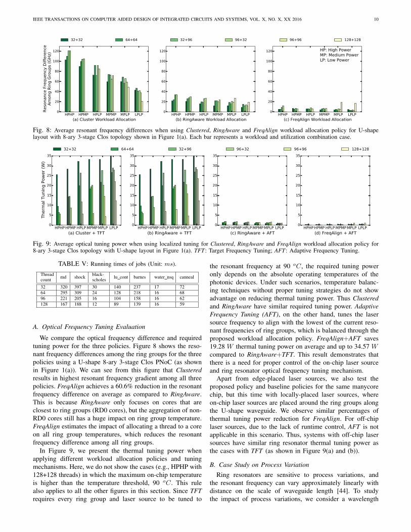
Fig. 8: Average resonant frequency differences when using Clustered, RingAware and FreqAlign workload allocation policy for U-shapelayout with 8-ary 3-stage Clos topology shown in Figure 1(a). Each bar represents a workload and utilization combination case.
HPHPHPMP HPLP MPMPMPLP LPLP
(a) Cluster + TFT
0
5
10
15
20
25
30
35
Therm
al Tunin
g P
ow
er
(W)
32+32 64+64 32+96 96+32 96+96 128+128
HPHPHPMP HPLP MPMPMPLP LPLP
(b) RingAware + TFT
0
5
10
15
20
25
30
35
HPHPHPMP HPLP MPMPMPLP LPLP
(c) RingAware + AFT
0
5
10
15
20
25
30
35
HPHPHPMP HPLP MPMPMPLP LPLP
(d) FreqAlign + AFT
0
5
10
15
20
25
30
35
Fig. 9: Average optical tuning power when using localized tuning for Clustered, RingAware and FreqAlign workload allocation policy for8-ary 3-stage Clos topology with U-shape layout in Figure 1(a). TFT: Target Frequency Tuning; AFT: Adaptive Frequency Tuning.
TABLE V: Running times of jobs (Unit: ms).
Threadcount md shock black-
scholes lu cont barnes water nsq canneal
32 320 397 30 140 237 17 7264 295 309 24 128 218 16 6896 221 205 16 104 158 16 62128 167 188 12 89 139 16 59
A. Optical Frequency Tuning Evaluation
We compare the optical frequency difference and requiredtuning power for the three policies. Figure 8 shows the reso-nant frequency differences among the ring groups for the threepolicies using a U-shape 8-ary 3-stage Clos PNoC (as shownin Figure 1(a)). We can see from this figure that Clusteredresults in highest resonant frequency gradient among all threepolicies. FreqAlign achieves a 60.6% reduction in the resonantfrequency difference on average as compared to RingAware.This is because RingAware only focuses on cores that areclosest to ring groups (RD0 cores), but the aggregation of non-RD0 cores still has a huge impact on ring group temperature.FreqAlign estimates the impact of allocating a thread to a coreon all ring group temperatures, which reduces the resonantfrequency difference among all ring groups.
In Figure 9, we present the thermal tuning power whenapplying different workload allocation policies and tuningmechanisms. Here, we do not show the cases (e.g., HPHP with128+128 threads) in which the maximum on-chip temperatureis higher than the temperature threshold, 90 oC. This rulealso applies to all the other figures in this section. Since TFTrequires every ring group and laser source to be tuned to
the resonant frequency at 90 oC, the required tuning poweronly depends on the absolute operating temperatures of thephotonic devices. Under such scenarios, temperature balanc-ing techniques without proper tuning strategies do not showadvantage on reducing thermal tuning power. Thus Clusteredand RingAware have similar required tuning power. AdaptiveFrequency Tuning (AFT), on the other hand, tunes the lasersource frequency to align with the lowest of the current reso-nant frequencies of ring groups, which is balanced through theproposed workload allocation policy. FreqAlign+AFT saves19.28 W thermal tuning power on average and up to 34.57 Wcompared to RingAware+TFT. This result demonstrates thatthere is a need for proper control of the on-chip laser sourceand ring resonator optical frequency tuning mechanism.
Apart from edge-placed laser sources, we also test theproposed policy and baseline policies for the same manycorechip, but this time with locally-placed laser sources, whereon-chip laser sources are placed around the ring groups alongthe U-shape waveguide. We observe similar percentages ofthermal tuning power reduction for FreqAlign. For off-chiplaser sources, due to the lack of runtime control, AFT is notapplicable in this scenario. Thus, systems with off-chip lasersources have similar ring resonator thermal tuning power asthe cases with TFT (as shown in Figure 9(a) and (b)).
B. Case Study on Process Variation
Ring resonators are sensitive to process variations, andthe resonant frequency can vary approximately linearly withdistance on the scale of waveguide length [44]. To studythe impact of process variations, we consider a wavelength
IEEE TRANSACTIONS ON COMPUTER AIDED DESIGN OF INTEGRATED CIRCUITS AND SYSTEMS, VOL. X, NO. X, XX 2016 11
HPHP HPMP HPLP MPMP MPLP LPLPRingAware Workload Allocation
0
20
40
60
80
100
Reso
nanc
e Fr
eque
ncy
Diffe
renc
e Am
ong
Ring
Gro
ups
(GHz
)32+32 64+64 32+96 96+32 96+96 128+128
HPHP HPMP HPLP MPMP MPLP LPLPFreqAlign Workload Allocation
0
20
40
60
80
100
(a) Horizontal process variation gradient. Average (maximum)power reduction is 1.83 W (2.77 W ), 62.9% (82.5%).
HPHP HPMP HPLP MPMP MPLP LPLPRingAware Workload Allocation
0
20
40
60
80
100
Reso
nanc
e Fr
eque
ncy
Diffe
renc
e Am
ong
Ring
Gro
ups
(GHz
)
32+32 64+64 32+96 96+32 96+96 128+128
HPHP HPMP HPLP MPMP MPLP LPLPFreqAlign Workload Allocation
0
20
40
60
80
100
(b) Vertical process variation gradient. Average (maximum) powerreduction is 1.81 W (2.91 W ), 64.7% (84.3%).
HPHP HPMP HPLP MPMP MPLP LPLPRingAware Workload Allocation
0
20
40
60
80
100
Reso
nanc
e Fr
eque
ncy
Diffe
renc
e Am
ong
Ring
Gro
ups
(GHz
)
32+32 64+64 32+96 96+32 96+96 128+128
HPHP HPMP HPLP MPMP MPLP LPLPFreqAlign Workload Allocation
0
20
40
60
80
100
(c) Maximum process variation among ring groups. Average (max-imum) power reduction is 2.04 W (3.26 W ), 60.1% (80.8%).
HPHP HPMP HPLP MPMP MPLP LPLPRingAware Workload Allocation
0
20
40
60
80
100
Reso
nanc
e Fr
eque
ncy
Diffe
renc
e Am
ong
Ring
Gro
ups
(GHz
)
32+32 64+64 32+96 96+32 96+96 128+128
HPHP HPMP HPLP MPMP MPLP LPLPFreqAlign Workload Allocation
0
20
40
60
80
100
(d) Maximum on-chip process variation. Average (maximum) powerreduction is 2.12 W (3.13 W ), 61.4% (76.2%).
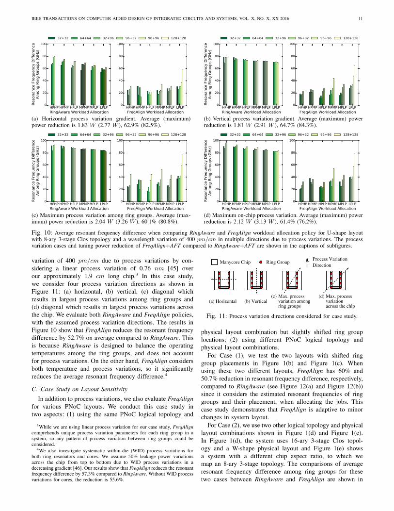
Fig. 10: Average resonant frequency difference when comparing RingAware and FreqAlign workload allocation policy for U-shape layoutwith 8-ary 3-stage Clos topology and a wavelength variation of 400 pm/cm in multiple directions due to process variations. The processvariation cases and tuning power reduction of FreqAlign+AFT compared to RingAware+AFT are shown in the captions of subfigures.
variation of 400 pm/cm due to process variations by con-sidering a linear process variation of 0.76 nm [45] overour approximately 1.9 cm long chip.3 In this case study,we consider four process variation directions as shown inFigure 11: (a) horizontal, (b) vertical, (c) diagonal whichresults in largest process variations among ring groups and(d) diagonal which results in largest process variations acrossthe chip. We evaluate both RingAware and FreqAlign policies,with the assumed process variation directions. The results inFigure 10 show that FreqAlign reduces the resonant frequencydifference by 52.7% on average compared to RingAware. Thisis because RingAware is designed to balance the operatingtemperatures among the ring groups, and does not accountfor process variations. On the other hand, FreqAlign considersboth temperature and process variations, so it significantlyreduces the average resonant frequency difference.4
C. Case Study on Layout Sensitivity
In addition to process variations, we also evaluate FreqAlignfor various PNoC layouts. We conduct this case study intwo aspects: (1) using the same PNoC logical topology and
3While we are using linear process variation for our case study, FreqAligncomprehends unique process variation parameters for each ring group in asystem, so any pattern of process variation between ring groups could beconsidered.
4We also investigate systematic within-die (WID) process variations forboth ring resonators and cores. We assume 50% leakage power variationsacross the chip from top to bottom due to WID process variations in adecreasing gradient [46]. Our results show that FreqAlign reduces the resonantfrequency difference by 57.3% compared to RingAware. Without WID processvariations for cores, the reduction is 55.6%.
Manycore Chip Ring Group
Max. process
Process Variation Direction
(a) Horizontal (b) Vertical(c) Max. process (d)
ring groupsvariation among
across the chipvariation
Fig. 11: Process variation directions considered for case study.
physical layout combination but slightly shifted ring grouplocations; (2) using different PNoC logical topology andphysical layout combinations.
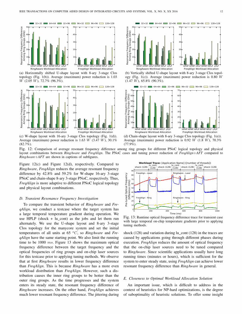
For Case (1), we test the two layouts with shifted ringgroup placements in Figure 1(b) and Figure 1(c). Whenusing these two different layouts, FreqAlign has 60% and50.7% reduction in resonant frequency difference, respectively,compared to RingAware (see Figure 12(a) and Figure 12(b))since it considers the estimated resonant frequencies of ringgroups and their placement, when allocating the jobs. Thiscase study demonstrates that FreqAlign is adaptive to minorchanges in system layout.
For Case (2), we use two other logical topology and physicallayout combinations shown in Figure 1(d) and Figure 1(e).In Figure 1(d), the system uses 16-ary 3-stage Clos topol-ogy and a W-shape physical layout and Figure 1(e) showsa system with a different chip aspect ratio, to which wemap an 8-ary 3-stage topology. The comparisons of averageresonant frequency difference among ring groups for thesetwo cases between RingAware and FreqAlign are shown in
IEEE TRANSACTIONS ON COMPUTER AIDED DESIGN OF INTEGRATED CIRCUITS AND SYSTEMS, VOL. X, NO. X, XX 2016 12
HPHP HPMP HPLP MPMP MPLP LPLPRingAware Workload Allocation
0
10
20
30
40
50
Reso
nanc
e Fr
eque
ncy
Diffe
renc
e Am
ong
Ring
Gro
ups
(GHz
)32+32 64+64 32+96 96+32 96+96 128+128
HPHP HPMP HPLP MPMP MPLP LPLPFreqAlign Workload Allocation
0
10
20
30
40
50
(a) Horizontally shifted U-shape layout with 8-ary 3-stage Clostopology (Fig. 1(b)). Average (maximum) power reduction is 1.03W (2.05 W ), 72.7% (96.3%).
HPHP HPMP HPLP MPMP MPLP LPLPRingAware Workload Allocation
0
10
20
30
40
50
Reso
nanc
e Fr
eque
ncy
Diffe
renc
e Am
ong
Ring
Gro
ups
(GHz
)
32+32 64+64 32+96 96+32 96+96 128+128
HPHP HPMP HPLP MPMP MPLP LPLPFreqAlign Workload Allocation
0
10
20
30
40
50
(b) Vertically shifted U-shape layout with 8-ary 3-stage Clos topol-ogy (Fig. 1(c)). Average (maximum) power reduction is 0.80 W(1.47 W ), 65.8% (90.3%).
HPHP HPMP HPLP MPMP MPLP LPLPRingAware Workload Allocation
0
10
20
30
40
50
Reso
nanc
e Fr
eque
ncy
Diffe
renc
e Am
ong
Ring
Gro
ups
(GHz
)
32+32 64+64 32+96 96+32 96+96 128+128
HPHP HPMP HPLP MPMP MPLP LPLPFreqAlign Workload Allocation
0
10
20
30
40
50
(c) W-shape layout with 16-ary 3-stage Clos topology (Fig. 1(d)).Average (maximum) power reduction is 1.63 W (3.47 W ), 30.1%(82.7%).
HPHP HPMP HPLP MPMP MPLP LPLPRingAware Workload Allocation
0
10
20
30
40
50
60
70
Reso
nanc
e Fr
eque
ncy
Diffe
renc
e Am
ong
Ring
Gro
ups
(GHz
)
32+32 64+64 32+96 96+32 96+96 128+128
HPHP HPMP HPLP MPMP MPLP LPLPFreqAlign Workload Allocation
0
10
20
30
40
50
60
70
(d) Chain-shape layout with 8-ary 3-stage Clos topology (Fig. 1(e)).Average (maximum) power reduction is 0.92 W (1.8 W ), 70.3%(77.9%).
Fig. 12: Comparison of average resonant frequency difference among ring groups for different PNoC logical topology and physicallayout combinations between RingAware and FreqAlign. The PNoC cases and tuning power reduction of FreqAlign+AFT compared toRingAware+AFT are shown in captions of subfigures.
Figure 12(c) and Figure 12(d), respectively. Compared toRingAware, FreqAlign reduces the average resonant frequencydifference by 42.8% and 59.2% for W-shape 16-ary 3-stagePNoC and chain-shape 8-ary 3-stage PNoC, respectively. Thus,FreqAlign is more adaptive to different PNoC logical topologyand physical layout combinations.
D. Transient Resonance Frequency Investigation
To compare the transient behavior of RingAware and Fre-qAlign, we conduct a testcase where the target system hasa large temporal temperature gradient during operation. Weuse HPLP (shock + lu cont) as the jobs and let them runalternately. We use the U-shape layout and 8-ary 3-stageClos topology for the manycore system and set the initialtemperatures of all units at 65 oC, so RingAware and Fre-qAlign have the same starting point. We also limit the runningtime to be 1000 ms. Figure 13 shows the maximum opticalfrequency difference between the target frequency and theoptical frequencies of ring groups and on-chip laser sourcesfor this testcase prior to applying tuning methods. We observethat at first RingAware results in lower frequency differencethan FreqAlign. This is because RingAware has a more evenworkload distribution than FreqAlign. However, such a dis-tribution causes the inner ring groups to be hotter than theouter ring groups. As the time progresses and the systementers its steady state, the resonant frequency difference ofRingAware increases. On the other hand, FreqAlign achievesmuch lower resonant frequency difference. The jittering during
0 200 400 600 800 1000
Time (ms)
0
10
20
30
40
50
60
70
80
90
RingAware - RingFreqAlign - Ring
RingAware - LaserFreqAlign - Laser
Pre
-tun
ed
Op
tica
l Fr
eq
uency
Diff
ere
nce
(G
Hz)
shock (128)lucont(128)
shock (128)lucont(128)
shock (128)lucont(128)
shock (128)
Workload Trace: [Application Name] ([number of threads])
shock (128)lu_cont(128) shock (128) shock (128) shock (128)
lu_cont(128)
lu_cont(128)
Fig. 13: Runtime optical frequency difference trace for transient casewith large temporal on-chip temperature gradients prior to applyingtuning methods.
shock (128) and variation during lu cont (128) in the traces arecaused by applications going through different phases duringexecution. FreqAlign reduces the amount of optical frequencythat the on-chip laser sources need to be tuned comparedto RingAware. Since scientific applications usually have longrunning times (minutes or hours), which is sufficient for thesystem to enter steady state, using FreqAlign can achieve lowerresonant frequency difference than RingAware in general.
E. Closeness to Optimal Workload Allocation Solution
An important issue, which is difficult to address in thecontext of heuristics for NP-hard optimizations, is the degreeof suboptimality of heuristic solutions. To offer some insight
IEEE TRANSACTIONS ON COMPUTER AIDED DESIGN OF INTEGRATED CIRCUITS AND SYSTEMS, VOL. X, NO. X, XX 2016 13
into the quality of FreqAlign workload allocation solutionsrelative to optimal solutions, we have studied the variousheuristics on a smaller chip architecture (a 2×4-core systemwith 2 ring groups placed on the two shorter opposite edges).This is because finding the optimal solution is practicallyinfeasible for larger systems (N ! workload allocation solutionsfor a fully utilized N -core system). For the 2×4 system,we run all 10080 workload allocation solutions (10080 = 8!/ 4 after accounting for horizontal and vertical symmetries)for ten power profiles generated by picking power numbersrandomly between 0.4 W and 2.8 W for each core. Onaverage, FreqAlign results in lower resonant frequency dif-ference between two ring groups than 87.7% of all workloadallocation solutions, while RingAware outperforms 69.3% ofall workload allocation solutions. This suggests that FreqAlignreturns solutions that are substantially closer to optimal thanthose of RingAware. We leave the closing of this suboptimalitygap for future research.
VII. CONCLUSION
PNoC is a promising replacement for ENoC in manycoresystems. Adoption of PNoC relies on developing techniquesthat efficiently manage the optical frequencies of the opticaldevices. In this paper, we propose a novel workload allocationpolicy accompanied by an adaptive tuning technique to alignthe optical frequencies of on-chip laser sources and ringresonators. Our policy, FreqAlign with adaptive frequencytuning, aligns the resonant frequency of the ring groupsinstead of aligning the temperature, and hence it can jointlycompensate for the difference in the optical frequency dueto thermal and process variations, which in turn reduces thepower consumed in localized thermal tuning. This is the firsttime resonant frequency matching of on-chip laser sourcesand ring resonators has been investigated, and their transientimpact considered with dynamic workload allocation. Theexperimental results demonstrate that the proposed FreqAlignpolicy performs significantly better than our previously pro-posed workload allocation policy RingAware, especially forsystems with process variation in ring resonators. We alsodemonstrate that FreqAlign achieves similar benefits acrosssystems with different PNoC logical topology and physicallayout combinations. More specifically, adaptively tuning theon-chip optical devices reduces the localized tuning power by19.28 W on average and by as large as 34.57 W .
REFERENCES
[1] A. Shacham, K. Bergman and L. P. Carloni, “On the Design of a PhotonicNetwork-on-Chip”, Proc. International Symposium on Networks-on-Chip,2007, pp. 53-64.
[2] A. Joshi, C. Batten, Y. Kwon, S. Beamer, I. Shamim, K. Asanovicand V. Stojanovic, “Silicon-photonic Clos Networks for Global On-chipCommunication”, Proc. International Symposium on Networks-on-Chip,2009, pp. 124-133.
[3] Y. Pan, P. Kumar, J. Kim, G. Memik, Y. Zhang and A. Choudhary,“Firefly: Illuminating Future Network-on-Chip with Nanophotonics”,Proc. International Symposium on Computer Architecture, 2009, pp. 429-440.
[4] D. Vantrease, R. Schreiber, M. Monchiero, M. McLaren, N. Jouppi,M. Fiorentino, A. Davis, N. Binkert, R. Beausoleil and J. Ahn, “Corona:System Implications of Emerging Nanophotonic Technology”, Proc.International Symposium on Computer Architecture, 2008, pp. 153-164.
[5] M. Cianchetti, J. C. Kerekes and D. H. Albonesi, “Phastlane: A RapidTransit Optical Routing Network”, Proc. International Symposium onComputer Architecture, 2009, pp. 441-450.
[6] C. DeRose, M. Watts, D. Trotter, D. Luck, G. Nielson and R. Young,“Silicon Microring Modulator with Integrated Heater and TemperatureSensor for Thermal Control”, Proc. Conference on Lasers and Electro-Optics and Quantum Electronics and Laser Science, 2010, pp. 1-2.
[7] M. Heck and J. Bowers, “Energy Efficient and Energy ProportionalOptical Interconnects for Multi-core Processors: Driving the Need for On-chip Sources”, IEEE Journal of Selected Topics in Quantum Electronics20(4)(2014), pp. 1-12.
[8] T. Zhang, J. Abellan, A. Joshi and A. Coskun, “Thermal Managementof Manycore Systems with Silicon-photonic Networks”, Proc. Design,Automation and Test in Europe Conference and Exhibition, 2014, pp.1-6.
[9] S. S. Djordjevic, K. Shang, B. Guan, S. T. S. Cheung, L. Liao, J. Basak,H.-F. Liu and S. J. B. Yoo, “CMOS-compatible, Athermal Silicon RingModulators Clad with Titanium Dioxide”, Optics Express 21(12)(2013),pp. 958-968.
[10] J. A. Cox, D. C. Trotter and A. L. Starbuck, “Integrated Control ofSilicon-photonic Micro-resonator Wavelength via Balanced HomodyneLocking”, Proc. IEEE Optical Interconnects Conference, 2013, pp. 52-53.
[11] D. Calhoun, Q. Li, C. Browning, N. C. Abrams, Y. Liu, R. Ding,L. P. Barry, T. W. Baehr-Jones, M. Hochberg and K. Bergman, “Pro-grammable Wavelength Locking and Routing in a Silicon-photonic Inter-connection Network Implementation”, Proc. OSA Optical Fiber Commu-nication Conference, 2015, pp. Tu2H-3.
[12] Y. Demir and N. Hardavellas, “Parka: Thermally Insulated NanophotonicInterconnects”, Proc. International Symposium on Networks-on-Chip,2015, pp. 1-8.
[13] C. Nitta, M. Farrens and V. Akella, “Addressing System-level TrimmingIssues in On-chip Nanophotonic Networks”, Proc. International Sympo-sium on High Performance Computer Architecture, 2011, pp. 122-131.
[14] Z. Li, A. Qouneh, M. Joshi, W. Zhang, X. Fu and T. Li, “Aurora: ACross-layer Solution for Thermally Resilient Photonic Network-on-Chip”,IEEE Transactions on Very Large Scale Integration Systems 23(1)(2015),pp. 170-183.
[15] S. Manipatruni, R. K. Dokania, B. Schmidt, N. Sherwood-Droz, C. B.Poitras, A. B. Apsel and M. Lipson, “Wide Temperature Range Operationof Micrometer-scale Silicon Electro-optic Modulators”, Optics Letters33(19)(2008), pp. 2185-2187.
[16] J. Howard, S. Dighe, S. Vangal, G. Ruhl, N. Borkar, S. Jain, V. Er-raguntla, M. Konow, M. Riepen, M. Gries, G. Droege, T. Lund-Larsen,S. Steibl, S. Borkar, V. De and R. Van Der Wijngaart, “A 48-core IA-32Processor in 45 nm CMOS Using On-die Message-passing and DVFS forPerformance and Power Scaling”, IEEE Journal of Solid-State Circuits46(1)(2011), pp. 173-183.
[17] “SPARC T4 Processor Data Sheet,” http://www.oracle.com/us/products/servers-storage/servers/sparc-enterprise/t-series/sparc-t4-processor-ds-497205.pdf. Online: accessed May 5, 2016.
[18] J. S. Orcutt, B. Moss, C. Sun, J. Leu, M. Georgas, J. Shainline,E. Zgraggen, H. Li, J. Sun, M. Weaver, S. Urosevic, M. Popovic, R. J.Ram and V. Stojanovic, “Open Foundry Platform for High-performanceElectronic-photonic Integration”, Optics Express 20(11)(2012), pp. 222-232.
[19] B. Moss, C. Sun, M. Georgas, J. Shainline, J. Orcutt, J. Leu, M. Wade,Y.-H. Chen, K. Nammari, X. Wang, H. Li, R. Ram, M. Popovicand V. Stojanovic, “A 1.23pJ/b 2.5Gb/s Monolithically Integrated Op-tical Carrier-injection Ring Modulator and All-digital Driver Circuit inCommercial 45nm SOI”, Proc. IEEE International Solid-State CircuitsConference, 2013, pp. 126-127.
[20] M. Georgas, B. Moss, C. Sun, J. Shainline, J. Orcutt, M. Wade, Y.-H. Chen, K. Nammari, J. Leu, A. Srinivasan, R. Ram, M. Popovicand V. Stojanovic, “A Monolithically-integrated Optical Transmitter andReceiver in a Zero-change 45nm SOI Process”, Proc. Symposium on VLSICircuits Digest of Technical Papers, 2014, pp. 1-2.
[21] H. Li, A. Fourmigue, S. Le Beux, X. Letartre, I. O’Connor andG. Nicolescu, “Thermal Aware Design Method for VCSEL-based On-chip Optical Interconnect”, Proc. Design, Automation and Test in EuropeConference and Exhibition, 2015, pp. 1120-1125.
[22] B. Song, P. Contu, C. Stagarescu, S. Pinna, P. Abolghasem, S. Ristic,N. Bickel, J. Bowker, A. Behfar and J. Klamkin, “3D Integrated HybridSilicon Laser”, Proc. European Conference on Optical Communication,2015, pp. 1-3.
IEEE TRANSACTIONS ON COMPUTER AIDED DESIGN OF INTEGRATED CIRCUITS AND SYSTEMS, VOL. X, NO. X, XX 2016 14
[23] T. Wang, H. Liu, A. Lee, F. Pozzi and A. Seeds, “1.3-µm InAs/GaAsQuantum-dot Lasers Monolithically Grown on Si Substrates”, OpticsExpress 19(12)(2011), pp. 11381-11386.
[24] S. Lourdudoss, “Heteroepitaxy and Selective Area Heteroepitaxy forSilicon Photonics”, Current Opinion in Solid State and Materials Science16(2)(2012), pp. 91-99.
[25] S. Woo, M. Ohara, E. Torrie, J. Singh and A. Gupta, “The SPLASH-2 Programs: Characterization and Methodological Considerations”, Proc.International Symposium on Computer Architecture, 1995, pp. 24-36.
[26] C. Bienia, S. Kumar, J. P. Singh and K. Li, “The PARSEC BenchmarkSuite: Characterization and Architectural Implications”, Proc. Interna-tional Conference on Parallel Architectures and Compilation Techniques,2008, pp. 72-81.
[27] D. Campbell, D. Bader, S. Brandt, D. Cook, M. Gokhale, R. Hornung,J. Keasler, P. LeBlanc, G. Marin, B. Mulvaney, M. Richards, J. Vetter andI.Walker, “Ubiquitous High Performance Computing: Challenge ProblemsSpecification”, Georgia Institute of Technology, Tech. Rep. HR0011-10-C-0145, 2012.
[28] T. Baehr-Jones, R. Ding, A. Ayazi, T. Pinguet, M. Streshinsky, N. Harris,J. Li, L. He, M. Gould, Y. Zhang, A. E. Lim, T. Liow, S. H. Teo, G. Loand M. Hochberg, “A 25 Gb/s Silicon Photonics Platform”, arXiv preprintarXiv:1203.0767, 2012.
[29] T. Carlson, W. Heirman and L. Eeckhout, “Sniper: Exploring the Levelof Abstraction for Scalable and Accurate Parallel Multi-core Simula-tions”, Proc. International Conference for High Performance Computing,Networking, Storage and Analysis, 2011, pp. 1-12.
[30] S. Li, J.-H. Ahn, R. Strong, J. Brockman, D. Tullsen and N. Jouppi,“McPAT: An Integrated Power, Area, and Timing Modeling Frameworkfor Multicore and Manycore Architectures”, Proc. International Sympo-sium on Microarchitecture, 2009, pp. 469-480.
[31] D. Tarjan, S. Thoziyoor and N. P. Jouppi, “CACTI 4.0”, HP LaboratoriesPalo Alto, Tech. Rep. HPL-2006-86, 2006.
[32] K. Skadron, M. Stan, W. Huang, S. Velusamy, K. Sankaranarayanan andD. Tarjan, “Temperature-aware Microarchitecture”, Proc. InternationalSymposium on Computer Architecture, 2003, pp. 2-13.
[33] J. Meng, K. Kawakami and A. Coskun, “Optimizing Energy Efficiencyof 3-D Multicore Systems with Stacked DRAM under Power and ThermalConstraints”, Proc. Design Automation Conference, 2012, pp. 648-655.
[34] H. Su, F. Liu, A. Devgan, E. Acar and S. Nassif, “Full Chip Leakage-estimation Considering Power Supply and Temperature Variations”, Proc.International Symposium on Low Power Electronics and Design, 2003,pp. 78-83.
[35] H. Wong, “A Comparison of Intel’s 32nm and 22nm Corei5 CPUs: Power, Voltage, Temperature, and Frequency”,http://blog.stuffedcow.net/2012/10/intel32nm-22nm-core-i5-comparison/.Online: accessed September 3, 2013.
[36] L. A. Coldren, S. W. Corzine and M. L. Mashanovitch, “Diode Lasersand Photonic Integrated Circuits”, Hoboken, Wiley, 2012.
[37] C. Chen, T. Zhang, P. Contu, J. Klamkin, A. K. Coskun and A. Joshi,“Sharing and Placement of On-chip Laser Sources in Silicon-photonicNoCs”, Proc. International Symposium on Networks-on-Chip, 2014, pp.88-95.
[38] M. Larson, A. Bhardwaj, W. Xiong, Y. Feng, X. D. Huang, K. Petrov,M. Moewe, H. Ji, A. Semakov, C. Lv, S. Kutty, A. Patwardhan, N. Liu,Z. Li, Y. Bao, Z. Shen, S. Bajwa, F. Zhou and P.-C. Koh, “NarrowLinewidth Sampled-grating Distributed Bragg Reflector Laser with En-hanced Side-mode Suppression”, Proc. Optical Fiber CommunicationConference and Exhibition, 2015, pp. 1-3.
[39] T. Kimoto, T. Shinagawa, T. Mukaihara, H. Nasu, S. Tamura, T. Numuraand A. Kasukawa, “Highly Reliable 40-mW 25-GHz× 20-ch ThermallyTunable DFB Laser Module Integrated with Wavelength Monitor”, Fu-rukawa Review 24(2003), pp. 1-5.
[40] P. Dong, R. Shafiiha, S. Liao, H. Liang, N.-N. Feng, D. Feng, G. Li,X. Zheng, A. V. Krishnamoorthy and M. Asghari, “Wavelength-tunableSilicon Microring Modulator”, Optics Express 18(11)(2010), pp. 941-946.
[41] K. Van Craeynest, S. Akram, W. Heirman, A. Jaleel and L. Eeckhout,“Fairness-aware Scheduling on Single-isa Heterogeneous Multi-cores”,Proc. International Conference on Parallel Architectures and CompilationTechniques, 2013, pp. 177-188.
[42] K. Van Craeynest, A. Jaleel, L. Eeckhout, P. Narvaez and J. Emer,“Scheduling Heterogeneous Multi-cores Through Performance ImpactEstimation (PIE)”, Proc. International Symposium on Computer Archi-tecture, 2012, pp. 213-224.
[43] “Benchmark Native Execution,” http://snipersim.org/documents/gainestown-native.html. Online: accessed Feburary 25, 2016.
[44] W. Zortman, D. Trotter and M. Watts, “Silicon Photonics Manufactur-ing”, Optics Express 18(2010), pp. 23598-23607.
[45] M. Mohamed, Z. Li, X. Chen, L. Shang, A. Mickelson, M. Vachharajaniand Y. Sun, “Power-efficient Variation-aware Photonic On-chip NetworkManagement”, Proc. International Symposium on Low-Power Electronicsand Design, 2010, pp. 31-36.
[46] S. Dighe, S. Vangal, P. Aseron, S. Kumar, T. Jacob, K. BowmanJ. Howard, J. Tschanz, V. Erraguntla, N. Borkar, V. De and S. Borkar,“Within-Die Variation-Aware Dynamic-Voltage-Frequency-Scaling WithOptimal Core Allocation and Thread Hopping for the 80-Core Ter-aFLOPS Processor”, IEEE Journal of Solid-State Circuits 46(1)(2011),pp. 184-193.
Jose L. Abellan (S’07-M’08) is an assistant professor at the ComputerScience Department of Catholic University of Murcia. His research interestsinclude GPU architectures, networks-on-chips, high performance computing,and emerging silicon photonics technology. He received the Ph.D. degree inComputer Science and Engineering from the University of Murcia.
Ayse K. Coskun (M’06) is an associate professor at the Electrical and Com-puter Engineering Department of Boston University. Her research interestsinclude energy-efficient computing, 3-D stack architectures, and embeddedsystems and software. She received the Ph.D. degree in Computer Scienceand Engineering from the University of California, San Diego.
Anjun Gu (S’12) is a Ph.D. student at the Electrical and Computer Engi-neering Department of the University of California, San Diego. His researchinterests include 3-D IC physical implementation flow and design marginreduction and signoff. He received the B.S. degree in Electrical and ComputerEngineering from the University of Texas, Austin.
Warren Jin is a Ph.D. student at the Electrical Engineering Department ofthe University of California, Santa Barbara. His research interests includeoptoelectronics and photonics. He received the B.S. degree in ComputerEngineering from Brown University.
Ajay Joshi (S’99-M’07) is an associate professor at the Electrical and Com-puter Engineering Department of Boston University. His research interestsinclude VLSI design and emerging device technologies including siliconphotonics and memristors. He received the Ph.D. degree in Electrical andComputer Engineering from Georgia Institute of Technology.
Andrew B. Kahng (M’03-SM’07-F’10) is a professor at the ComputerScience Engineering Department and Electrical and the Computer EngineeringDepartment of the University of California, San Diego. His interests include ICphysical design, the design-manufacturing interface, combinatorial optimiza-tion, and technology roadmapping. He received the Ph.D. degree in ComputerScience from the University of California, San Diego.
Jonathan Klamkin (SM’14) is an associate professor at the Electrical andComputer Engineering Department of the University of California, Santa Bar-bara. His research interests include photonic integrated circuits and devices,widely-tunable lasers, and semiconductor optical amplifiers. He received thePh.D. degree in Electronic Materials from the University of California, SantaBarbara.
Cristian Morales is a Ph.D. student at the Electrical and Computer Engineer-ing Department of Boston University. His research interests include thermalmodeling and management of systems with silicon photonic networks. Hereceived the B.S. degree in Electrical Engineering from Boston University.
John Recchio (S’11) is a Ph.D. student at the Electrical and ComputerEngineering Department of the University of California, San Diego. Hisresearch interests include photonic integrated circuits and networks. Hereceived his B.S. degree in Electrical and Computer Engineering from theUniversity of California, San Diego.
Vaishnav Srinivas (M’02) is a Ph.D. student at the Electrical and ComputerEngineering Department of the University of California, San Diego. Hiscurrent research interests include low-power interfaces, IO and memoryarchitecture, and roadmapping interface technology. He received the M.S.degree from the University of California, Los Angeles.
Tiansheng Zhang (S’12) is a Ph.D. student at the Electrical and ComputerEngineering Department of Boston University. His research interests include3-D stack architectures, silicon photonic NoCs, and resource and thermalmanagement on manycore systems. He received the B.S. degree in ElectricalEngineering from Harbin Institute of Technology.


![University of California, San Diego (UCSD), La Jolla, CA 92093, … · 2010-09-14 · University of California, San Diego (UCSD), La Jolla, CA 92093, USA ... Sitter space [8{10]](https://img.pdfslide.net/doc/110x75/5f915effefb0ec12e81a6444/university-of-california-san-diego-ucsd-la-jolla-ca-92093-2010-09-14-university.jpg)