Embed Size (px)
Citation preview
Model Estimation and Selection towardsUnconstrained Real-Time Tracking and Mapping
Steffen Gauglitz, Student Member, IEEE , Chris Sweeney, Student Member, IEEE ,
Jonathan Ventura, Member, IEEE , Matthew Turk, Fellow, IEEE , and Tobias H€ollerer, Member, IEEE
Abstract—We present an approach and prototype implementation to initialization-free real-time tracking and mapping that supports
any type of camera motion in 3D environments, that is, parallax-inducing as well as rotation-only motions. Our approach effectively
behaves like a keyframe-based Simultaneous Localization and Mapping system or a panorama tracking and mapping system,
depending on the camera movement. It seamlessly switches between the two modes and is thus able to track and map through
arbitrary sequences of parallax-inducing and rotation-only camera movements. The system integrates both model-based and model-
free tracking, automatically choosing between the two depending on the situation, and subsequently uses the “Geometric Robust
Information Criterion” to decide whether the current camera motion can best be represented as a parallax-inducing motion or a rotation-
only motion. It continues to collect and map data after tracking failure by creating separate tracks which are later merged if they are
found to overlap. This is in contrast to most existing tracking and mapping systems, which suspend tracking and mapping and thus
discard valuable data until relocalization with respect to the initial map is successful. We tested our prototype implementation on a
variety of video sequences, successfully tracking through different camera motions and fully automatically building combinations of
panoramas and 3D structure.
Index Terms—Visual tracking, simultaneous localization and mapping, panorama mapping, model selection, GRIC score, keyframe-based,
initialization-free, augmented reality
Ç
1 INTRODUCTION
OVER the past decade, there has been a tremendousamount of work on real-time monocular vision-
based tracking and mapping (T&M) systems, that is, sys-tems that simultaneously determine the position and/ororientation of the camera with respect to a previouslyunknown environment and create a model of this envi-ronment. In addition to other applications, T&M is animportant enabling technology for Augmented Reality(AR) in unprepared environments.
Two important characteristics of a T&M system are thetype of camera motion and the geometry of the environmentthat it supports. For example, a system may assume a planarenvironment [31] or a camera that is rotating around itsoptical center [7], [42]. Simultaneous Localization and Map-ping (SLAM) systems such as [6], [8], [17], [27] can dealwith environments of arbitrary geometry and any cameramotion that induces parallax. However, with few exceptions[4], they do not support rotation-only camera motion: Theirmapping is intrinsically built upon triangulation of features;thus, they require that each feature be observed from two
distinct camera locations and may produce degeneratemaps or fail completely if the camera rotates from one partof the environment to another.
Therefore, most SLAM systems need to be initializedwith a distinct “traveling” movement of the camera foreach newly observed part of the environment, and therequired travel distance is directly proportional to the dis-tance to the environment. This restriction is acceptable forvehicle navigation or if building a model of the environ-ment is the user’s main intent. However, it is a major lim-itation for the use of SLAM systems in AR, where theenvironment modeling is assumed to be done in the back-ground and ideally transparent to the user, who shouldnot be required to move a certain way in order to makethe system work. Moreover, rotation-only “lookingaround” is a very natural motion and may occur in manyAR applications [21], [42].
Our particular motivation is the use of a T&M system forremote collaboration [10], where the emerging model of theenvironment is used to allow a physically remote user toview and navigate the environment, and AR annotationsthat are registered to this model are used to communicatevisual/spatial information. For this and many other appli-cations, the paradigm for modeling the environment shouldbe to make the best possible use of all data that can becasually collected and to enable viewing and placement ofannotations for as much time as possible. In particular, thismeans not forcing the user to concentrate on model build-ing, and not discarding all frames that stem from rotation-only movements (as in most SLAM systems) or translations(as with panorama mapping).
In this paper, we present an approach and prototypeimplementation that fulfills these criteria: We describe a
� S. Gauglitz, C. Sweeney, M. Turk, and T. H€ollerer are with the Depart-ment of Computer Science, University of California, Santa Barbara, SantaBarbara, CA 93106.E-mail: {sgauglitz, cmsweeney, mturk, holl}@cs.ucsb.edu.
� J. Ventura is with the Institute for Computer Graphics and Vision, GrazUniversity of Technology, Inffeldgasse 16, 8010 Graz, Austria.E-mail: [email protected].
Manuscript received 22 Feb. 2013; revised 5 Aug. 2013; accepted 3 Oct. 2013;published online xx xx xxxx.Recommended for acceptance by M. Gandy, K. Kiyokawa, and G. Reitmayr.For information on obtaining reprints of this article, please send an e-mail to:[email protected], and reference IEEECS Log NumberTVCGSI-2013-02-0049.Digital Object Identifier no. 10.1109/TVCG.2013.243
IEEE TRANSACTIONS ON VISUALIZATION AND COMPUTER GRAPHICS, VOL. 20, NO. X, XXXXX 2014 1
1077-2626/14/$31.00 � 2014 IEEE Published by the IEEE Computer Society
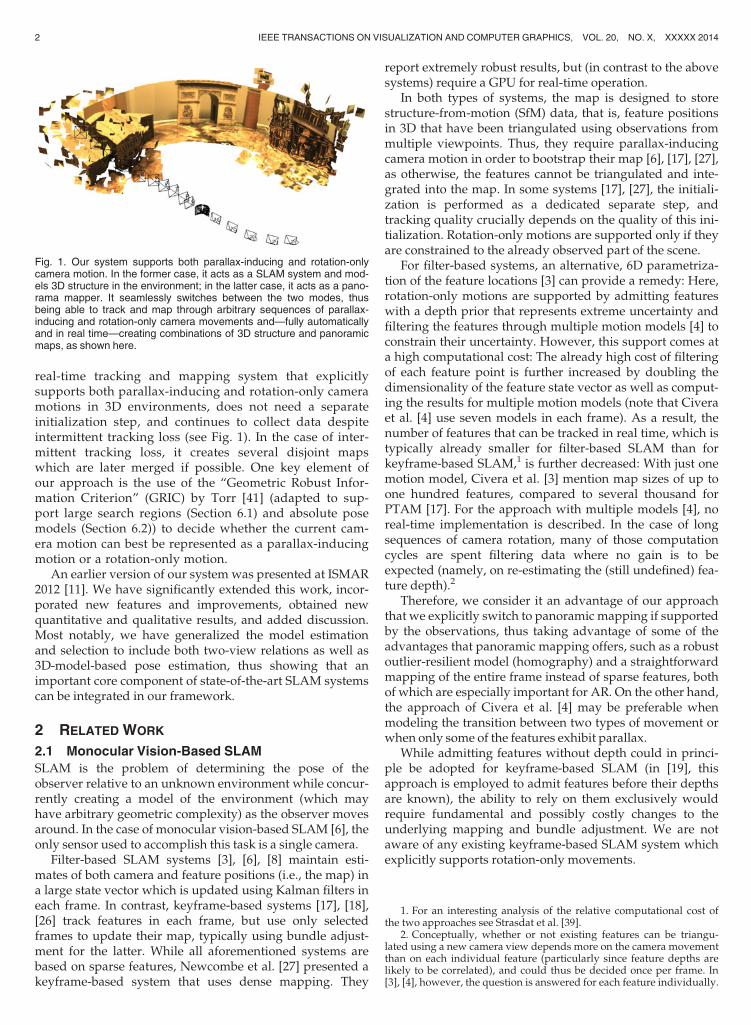
real-time tracking and mapping system that explicitlysupports both parallax-inducing and rotation-only cameramotions in 3D environments, does not need a separateinitialization step, and continues to collect data despiteintermittent tracking loss (see Fig. 1). In the case of inter-mittent tracking loss, it creates several disjoint mapswhich are later merged if possible. One key element ofour approach is the use of the “Geometric Robust Infor-mation Criterion” (GRIC) by Torr [41] (adapted to sup-port large search regions (Section 6.1) and absolute posemodels (Section 6.2)) to decide whether the current cam-era motion can best be represented as a parallax-inducingmotion or a rotation-only motion.
An earlier version of our system was presented at ISMAR2012 [11]. We have significantly extended this work, incor-porated new features and improvements, obtained newquantitative and qualitative results, and added discussion.Most notably, we have generalized the model estimationand selection to include both two-view relations as well as3D-model-based pose estimation, thus showing that animportant core component of state-of-the-art SLAM systemscan be integrated in our framework.
2 RELATED WORK
2.1 Monocular Vision-Based SLAM
SLAM is the problem of determining the pose of theobserver relative to an unknown environment while concur-rently creating a model of the environment (which mayhave arbitrary geometric complexity) as the observer movesaround. In the case of monocular vision-based SLAM [6], theonly sensor used to accomplish this task is a single camera.
Filter-based SLAM systems [3], [6], [8] maintain esti-mates of both camera and feature positions (i.e., the map) ina large state vector which is updated using Kalman filters ineach frame. In contrast, keyframe-based systems [17], [18],[26] track features in each frame, but use only selectedframes to update their map, typically using bundle adjust-ment for the latter. While all aforementioned systems arebased on sparse features, Newcombe et al. [27] presented akeyframe-based system that uses dense mapping. They
report extremely robust results, but (in contrast to the abovesystems) require a GPU for real-time operation.
In both types of systems, the map is designed to storestructure-from-motion (SfM) data, that is, feature positionsin 3D that have been triangulated using observations frommultiple viewpoints. Thus, they require parallax-inducingcamera motion in order to bootstrap their map [6], [17], [27],as otherwise, the features cannot be triangulated and inte-grated into the map. In some systems [17], [27], the initiali-zation is performed as a dedicated separate step, andtracking quality crucially depends on the quality of this ini-tialization. Rotation-only motions are supported only if theyare constrained to the already observed part of the scene.
For filter-based systems, an alternative, 6D parametriza-tion of the feature locations [3] can provide a remedy: Here,rotation-only motions are supported by admitting featureswith a depth prior that represents extreme uncertainty andfiltering the features through multiple motion models [4] toconstrain their uncertainty. However, this support comes ata high computational cost: The already high cost of filteringof each feature point is further increased by doubling thedimensionality of the feature state vector as well as comput-ing the results for multiple motion models (note that Civeraet al. [4] use seven models in each frame). As a result, thenumber of features that can be tracked in real time, which istypically already smaller for filter-based SLAM than forkeyframe-based SLAM,1 is further decreased: With just onemotion model, Civera et al. [3] mention map sizes of up toone hundred features, compared to several thousand forPTAM [17]. For the approach with multiple models [4], noreal-time implementation is described. In the case of longsequences of camera rotation, many of those computationcycles are spent filtering data where no gain is to beexpected (namely, on re-estimating the (still undefined) fea-ture depth).2
Therefore, we consider it an advantage of our approachthat we explicitly switch to panoramic mapping if supportedby the observations, thus taking advantage of some of theadvantages that panoramic mapping offers, such as a robustoutlier-resilient model (homography) and a straightforwardmapping of the entire frame instead of sparse features, bothof which are especially important for AR. On the other hand,the approach of Civera et al. [4] may be preferable whenmodeling the transition between two types of movement orwhen only some of the features exhibit parallax.
While admitting features without depth could in princi-ple be adopted for keyframe-based SLAM (in [19], thisapproach is employed to admit features before their depthsare known), the ability to rely on them exclusively wouldrequire fundamental and possibly costly changes to theunderlying mapping and bundle adjustment. We are notaware of any existing keyframe-based SLAM system whichexplicitly supports rotation-only movements.
Fig. 1. Our system supports both parallax-inducing and rotation-onlycamera motion. In the former case, it acts as a SLAM system and mod-els 3D structure in the environment; in the latter case, it acts as a pano-rama mapper. It seamlessly switches between the two modes, thusbeing able to track and map through arbitrary sequences of parallax-inducing and rotation-only camera movements and—fully automaticallyand in real time—creating combinations of 3D structure and panoramicmaps, as shown here.
1. For an interesting analysis of the relative computational cost ofthe two approaches see Strasdat et al. [39].
2. Conceptually, whether or not existing features can be triangu-lated using a new camera view depends more on the camera movementthan on each individual feature (particularly since feature depths arelikely to be correlated), and could thus be decided once per frame. In[3], [4], however, the question is answered for each feature individually.
2 IEEE TRANSACTIONS ON VISUALIZATION AND COMPUTER GRAPHICS, VOL. 20, NO. X, XXXXX 2014
2.2 Panorama Tracking and Mapping
Like a SLAM system, a panorama tracking and mappingsystem aims at modeling the environment while determin-ing the pose of the camera,3 but in this case, the camera isassumed to rotate around its optical center, so that only itsorientation has to be determined. An early real-time systemis Envisor [7]. Wagner et al. [42] describe a system that oper-ates robustly and in real time on a mobile device.
2.3 Stereo and Non-Visual Environment Modeling
In theory, using stereo cameras eliminates the problem ofrequiring the camera to travel, since the baseline required totriangulate features is built-in. In practice, however, usingstereo cameras is only a partial remedy, since the baselinehas to be significant in relation to the distance to the envi-ronment in order to reliably estimate depth. Thus, a wear-able stereo system would be unable to map a buildingacross the street without requiring the user to provide addi-tional baseline by traveling (while a panorama system,though unable to provide depth, would produce veryusable information).
Further, systems based on alternative sensor typesshould be considered. In particular, active depth sensorsbased on time-of-flight or structured light [22], [28] haverecently generated significant interest and can arguablyprovide for more detailed models and more robust track-ing when lighting conditions for vision-based trackingare unfavorable. However, all of these systems haveother inherent limitations such as limited range, inabilityto work in sunlight, power consumption, and need foradditional special hardware.
We thus argue that there are both theoretical and practi-cal interests in solving T&M using monocular vision.
2.4 Model Selection, GRIC Score and Applications
Model selection is defined as choosing the model thatbest describes a set of observations. Various metrics
(frequently dubbed “information criteria”) have beenproposed to assess the fitness of a particular model giventhe data, for example minimum description length [34],AIC [1], and BIC [36]. Torr described both a maximumlikelihood [40] and a Bayesian formulation [41] of GRIC,and we use the latter in this work. These information cri-teria are general in nature and can be applied to varioustypes of models. In SfM, the GRIC score has beenapplied particularly to detect homographies in order toavoid them during keyframe selection [32], [33]. In con-trast, we use the GRIC score to select between two mod-els, but we use the data in either case.
3 SYSTEM OVERVIEW
Our concept borrows two key ideas from Klein andMurray’s PTAM system [17], [18], [19], namely, the centralrole of keyframes and the splitting of tracking and mappinginto two parallel threads.
The split and design of the threads follows two guide-lines: 1) the tracking thread should be as fast as possibleand leave all tasks that are not imminent in order for thenext frame to be processed to the mapping thread, whichruns asynchronously in the background; and 2) the firststeps in the pipeline should not be dependent on the motionmodel (parallax-inducing versus rotation-only) that will beselected, in order to minimize redundant computations.
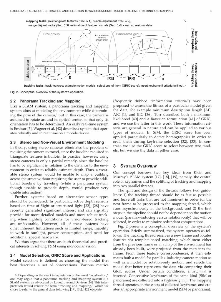
Fig. 2 presents a conceptual overview of the system’soperation. Briefly summarized, the system operates as fol-lows: The tracking thread receives a new frame and locatesfeatures via template-based matching, which stem eitherfrom the previous frame or, if a map of the environment hasalready been built, were projected from the map into theframe. From these feature correspondences, it then esti-mates both a model for parallax-inducing camera motion aswell as a model for rotation-only motion, and selects themodel that better represents the data via comparing theirGRIC scores. Under certain conditions, a keyframe isinserted. Consecutive keyframes of the same kind (SfM orpanorama) are collected into a keyframe group. The mappingthread operates on these sets of collected keyframes and cre-ates an appropriate environment model (SfM or panorama).
3. Depending on the exact interpretation of the word “localization,”one may argue that a panorama tracking and mapping system is aSLAM system, as advocated by Lovegrove and Davison [24]. This inter-pretation would render the term “tracking and mapping,” which wechose to refer to the general class following [17], [31], [42], obsolete.
Fig. 2. Conceptual overview of the system’s operation.
GAUGLITZ ET AL.: MODEL ESTIMATION AND SELECTION TOWARDS UNCONSTRAINED REAL-TIME TRACKING AND MAPPING 3
The tracking and mapping threads are described in detailin Sections 4 and 5, respectively. Section 6 describes theproblem of model selection and the GRIC score.
3.1 Two-View Relations and Model-Based Poses
Conceptually, two two-view relations (namely, the essen-tial matrix E and the homography H) are all-encompass-ing in that they describe all cases of camera movementsthat can occur in a static environment. Consequently, ourprevious implementation used only these two models[11]. However, this implementation does not make opti-mal use of the environment model that is built in the back-ground; by sequentially estimating E from potentiallysmall baselines, tracking remains relatively brittle and jit-tery (cf. Fig. 10).
Therefore, we have extended our concept to include bothtwo-view relations (for initialization, after tracking loss, orwhen rotating into uncharted territory) as well as twomodel-based absolute poses ½Rjt� and ½Rj0� 4 (whenever thecamera observes a part of the environment for which a 3Dmodel has been built). It should be noted that, in each frame,we still estimate only two models (the two-view relations orthe absolute pose models); thus, the computational load hasnot increased.
The integration of absolute pose models has two furtheradvantages: First, it allows to distinguish rotation-onlymovement from planar environments (which is difficult inthe model-free case, since in both cases, the resulting trans-formations are described by the same relation, namely, ahomography). Second, it decreases the risk of fragmentationof the model into connected sub-maps of alternating types(which a linear sequence of E’s and H’s may produce, asdiscussed in [11]), since the system can connect incomingframes directly to an existing model (rather than only to theprevious keyframe).
Why is estimating ½Rj0� necessary? Unlike in the case ofE versus H, when a model is available, the absolute pose½Rjt� is well-defined and can be estimated irrespective ofthe (relative) camera motion. Thus, it is less obvious whyestimating ½Rj0� and the subsequent model selection stepis necessary. We do so for the following reason: Considerthe case that the camera observes a known scene (thususing model-based tracking), then rotates towards unob-served parts of the scene. Due to the rotation-only move-ment, no new features can be triangulated. If ½Rjt� is theonly model-based pose that is estimated, and has priorityas long as enough triangulated features are visible, thesystem will switch to H only when very few (if any) ofthe existing features are left, risking tracking loss inbetween and generating a panorama that has very littleoverlap with the existing model. By estimating ½Rj0� andthus explicitly switching to panorama mode (if ½Rj0�proves to better represent the data), we can start buildingthe panorama immediately, ensuring that it is well-con-nected to the existing structure by the time the systemswitches to H, seamlessly continuing the panorama as itextends into newly observed parts of the scene.
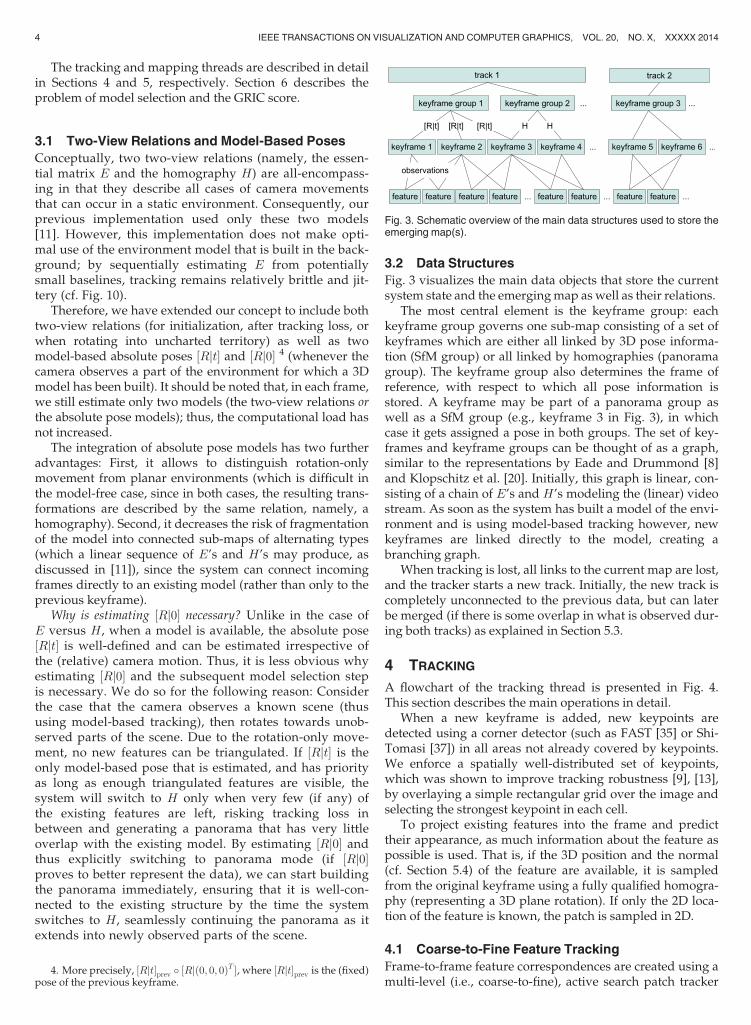
3.2 Data Structures
Fig. 3 visualizes the main data objects that store the currentsystem state and the emerging map as well as their relations.
The most central element is the keyframe group: eachkeyframe group governs one sub-map consisting of a set ofkeyframes which are either all linked by 3D pose informa-tion (SfM group) or all linked by homographies (panoramagroup). The keyframe group also determines the frame ofreference, with respect to which all pose information isstored. A keyframe may be part of a panorama group aswell as a SfM group (e.g., keyframe 3 in Fig. 3), in whichcase it gets assigned a pose in both groups. The set of key-frames and keyframe groups can be thought of as a graph,similar to the representations by Eade and Drummond [8]and Klopschitz et al. [20]. Initially, this graph is linear, con-sisting of a chain of E’s and H’s modeling the (linear) videostream. As soon as the system has built a model of the envi-ronment and is using model-based tracking however, newkeyframes are linked directly to the model, creating abranching graph.
When tracking is lost, all links to the current map are lost,and the tracker starts a new track. Initially, the new track iscompletely unconnected to the previous data, but can laterbe merged (if there is some overlap in what is observed dur-ing both tracks) as explained in Section 5.3.
4 TRACKING
A flowchart of the tracking thread is presented in Fig. 4.This section describes the main operations in detail.
When a new keyframe is added, new keypoints aredetected using a corner detector (such as FAST [35] or Shi-Tomasi [37]) in all areas not already covered by keypoints.We enforce a spatially well-distributed set of keypoints,which was shown to improve tracking robustness [9], [13],by overlaying a simple rectangular grid over the image andselecting the strongest keypoint in each cell.
To project existing features into the frame and predicttheir appearance, as much information about the feature aspossible is used. That is, if the 3D position and the normal(cf. Section 5.4) of the feature are available, it is sampledfrom the original keyframe using a fully qualified homogra-phy (representing a 3D plane rotation). If only the 2D loca-tion of the feature is known, the patch is sampled in 2D.
4.1 Coarse-to-Fine Feature Tracking
Frame-to-frame feature correspondences are created using amulti-level (i.e., coarse-to-fine), active search patch tracker
4. More precisely, ½Rjt�prev � ½Rjð0; 0; 0ÞT �, where ½Rjt�prev is the (fixed)
pose of the previous keyframe.
Fig. 3. Schematic overview of the main data structures used to store theemerging map(s).
4 IEEE TRANSACTIONS ON VISUALIZATION AND COMPUTER GRAPHICS, VOL. 20, NO. X, XXXXX 2014
with normalized cross-correlation (NCC)-based templatematching. On the full-resolution image, the feature locationis refined to subpixel accuracy by using a quadratic fit toneighboring scores.
This is similar to the keypoint tracking by other systems[17], [42], [43]; however in contrast to these system, themulti-level tracking is executed on a per-feature basis(instead of interleaved with the pose estimation), since wedo not know which type of camera motion to expect (andthus which model to enforce) until after the tracking step.We have designed, but not yet fully integrated, a moresophisticated approach that retains the advantages of theinterleaved pose estimation, and discuss this approach inSection 8.2.
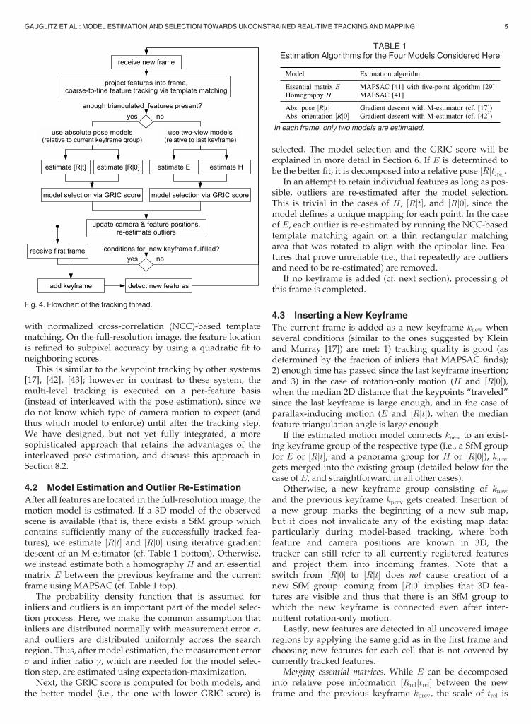
4.2 Model Estimation and Outlier Re-Estimation
After all features are located in the full-resolution image, themotion model is estimated. If a 3D model of the observedscene is available (that is, there exists a SfM group whichcontains sufficiently many of the successfully tracked fea-tures), we estimate ½Rjt� and ½Rj0� using iterative gradientdescent of an M-estimator (cf. Table 1 bottom). Otherwise,we instead estimate both a homography H and an essentialmatrix E between the previous keyframe and the currentframe using MAPSAC (cf. Table 1 top).
The probability density function that is assumed forinliers and outliers is an important part of the model selec-tion process. Here, we make the common assumption thatinliers are distributed normally with measurement error s,and outliers are distributed uniformly across the searchregion. Thus, after model estimation, the measurement errors and inlier ratio g, which are needed for the model selec-tion step, are estimated using expectation-maximization.
Next, the GRIC score is computed for both models, andthe better model (i.e., the one with lower GRIC score) is
selected. The model selection and the GRIC score will beexplained in more detail in Section 6. If E is determined tobe the better fit, it is decomposed into a relative pose ½Rjt�rel.
In an attempt to retain individual features as long as pos-sible, outliers are re-estimated after the model selection.This is trivial in the cases of H, ½Rjt�, and ½Rj0�, since themodel defines a unique mapping for each point. In the caseof E, each outlier is re-estimated by running the NCC-basedtemplate matching again on a thin rectangular matchingarea that was rotated to align with the epipolar line. Fea-tures that prove unreliable (i.e., that repeatedly are outliersand need to be re-estimated) are removed.
If no keyframe is added (cf. next section), processing ofthis frame is completed.
4.3 Inserting a New Keyframe
The current frame is added as a new keyframe knew whenseveral conditions (similar to the ones suggested by Kleinand Murray [17]) are met: 1) tracking quality is good (asdetermined by the fraction of inliers that MAPSAC finds);2) enough time has passed since the last keyframe insertion;and 3) in the case of rotation-only motion (H and ½Rj0�),when the median 2D distance that the keypoints “traveled”since the last keyframe is large enough, and in the case ofparallax-inducing motion (E and ½Rjt�), when the medianfeature triangulation angle is large enough.
If the estimated motion model connects knew to an exist-ing keyframe group of the respective type (i.e., a SfM groupfor E or ½Rjt�, and a panorama group for H or ½Rj0�), knew
gets merged into the existing group (detailed below for thecase of E, and straightforward in all other cases).
Otherwise, a new keyframe group consisting of knew
and the previous keyframe kprev gets created. Insertion ofa new group marks the beginning of a new sub-map,but it does not invalidate any of the existing map data:particularly during model-based tracking, where bothfeature and camera positions are known in 3D, thetracker can still refer to all currently registered featuresand project them into incoming frames. Note that aswitch from ½Rj0� to ½Rjt� does not cause creation of anew SfM group: coming from ½Rj0� implies that 3D fea-tures are visible and thus that there is an SfM group towhich the new keyframe is connected even after inter-mittent rotation-only motion.
Lastly, new features are detected in all uncovered imageregions by applying the same grid as in the first frame andchoosing new features for each cell that is not covered bycurrently tracked features.
Merging essential matrices. While E can be decomposedinto relative pose information ½Rreljtrel� between the newframe and the previous keyframe kprev, the scale of trel is
TABLE 1Estimation Algorithms for the Four Models Considered Here
In each frame, only two models are estimated.
Fig. 4. Flowchart of the tracking thread.
GAUGLITZ ET AL.: MODEL ESTIMATION AND SELECTION TOWARDS UNCONSTRAINED REAL-TIME TRACKING AND MAPPING 5
arbitrary. Before it can be integrated into an existing SfMgroup, a common scale has to be found. In order to do so,we use the set of all features that have been observed (andthus have a triangulated position) in both the existing SfMgroup as well as with respect to ½Rreljtrel�, and calculate theratios of their distances to kprev in both coordinate systems.We then take the median of those ratios as a robust measureof the scale between the two coordinate systems and scaletrel accordingly.
4.4 Relocalizing versus Starting a New Track
When tracking gets lost—i.e., when the number of inliersfor the selected model falls below a set threshold—thestandard strategy employed by most T&M systems (e.g.,[17], [31], [42]) is to continuously try to relocalize thecamera with respect to the current map with each newframe until successful. However, this means that track-ing and mapping are suspended and no data is collecteduntil relocalization is successful.
Here, we employ an alternative strategy proposed byEade and Drummond [8]: instead of trying to relocalize, westart a new track immediately, and leave it to the back-ground thread to merge tracks if possible (cf. Section 5.3).The benefit of this method, illustrated in Figs. 5 and 11, isthat the system continues to collect data even after trackingfailure occurs, and, if the tracks are later found to overlap,merges the created maps. If they do not overlap, the mapsremain separate. (Note that in this case, a recovery-basedsystem would never recover.)
5 MAPPING
The mapping thread runs in parallel to the tracking threadand is responsible for the following tasks:
1. triangulate new features,2. run bundle adjustment,3. merge disjoint tracks,4. estimate feature normals, and5. clean up residual data.These tasks are allowed to be more computationally
intensive than the tracker’s tasks, since the system does notdepend on them in order to process the next frame.
Each of the tasks gets assigned a priority which dependson the time it was last executed and the system’s currentstate. In each iteration, the task with highest priority is exe-cuted. For example, after a new keyframe is inserted, trian-gulation of new features becomes important; if tracking gotlost and thus a new track is started, merging of tracks is pri-oritized to enable quick merging of tracks. Thus, assumingthat the two threads run on two independent cores, the lat-ter can happen as quickly as conventional relocalization.
5.1 Triangulating Features
A feature that was observed in at least two keyframeswithin the same SfM group, but not bundle adjusted yet, istriangulated and gets assigned a 3D location with respect tothis group’s frame of reference. When the tracker adds anew keyframe with a new observation of a feature f , f is re-triangulated using all information when the mapper cyclesthrough this step the next time.
5.2 Bundle Adjustment
SfM groups with at least three keyframes get passedthrough a standard bundle adjuster [23] that globallyoptimizes all keyframe (i.e., camera) poses and featurepositions in this group’s frame of reference. If there aremultiple such groups, the group with the newest
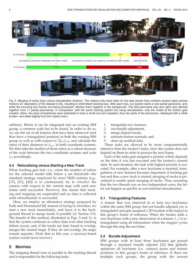
Fig. 5. Merging of tracks (top) versus relocalization (bottom). The rotation-only input video for the data shown here contains several rapid cameramotions (cf. description of the dataset in [5]), resulting in intermittent tracking loss. After each loss, our system starts a new partial panorama, and,while the incoming live frames are being processed, stitches them together in the background. The final panorama (top and right) was stitchedtogether from 11 partial panoramas. In comparison, with the same tracking system but using relocalization, only the model at the bottom getscreated. (Here, two pairs of keyframes were estimated to have a small non-zero baseline, thus two parts of the panorama—displayed with a whiteborder—are offset slightly from the rotation axis.)
6 IEEE TRANSACTIONS ON VISUALIZATION AND COMPUTER GRAPHICS, VOL. 20, NO. X, XXXXX 2014
keyframe (that is, the keyframe that got adjusted theleast number of times) is processed.
More sophisticated bundle adjustment strategies withlocal and global adjustment steps [17] could be integratedas needed.
5.3 Merging Disjoint Tracks
When tracking gets lost, the tracker immediately starts anew, independent track, rather than continuously tryingto relocalize with respect to the existing map. In doingso, the tracker continues to collect and “stitch together”data even though the spatial relation to the first map isinitially unknown.
The algorithm that merges tracks is similar to the key-frame-based recovery by Klein and Murray [18] (alsoused in [31], [42], among others): as observed by Eade andDrummond [8], recovery, loop closure, and (here) mergingof tracks are effectively similar to each other; the main dif-ference lies in when the algorithm is executed and how itsresult is used.
Whenever a new keyframe is taken, the system stores adownsampled, blurred copy of the image (here: 80� 60 pix-els, blurred with a Gaussian with s ¼ 1:5px), dubbed smallblurry image (SBI).
Merging of tracks is implemented as follows: The algo-rithm chooses a keyframe k1 and computes the NCC of itsSBI with the SBI of all other keyframes. Keyframes on thesame track as k1 are omitted, as are keyframes to which aprevious merge attempt failed. The keyframe k2 with thehighest NCC score is selected, and the SBIs of k1 and k2 arealigned to each other using inverse compositional imagealignment [2] of an affine homography HA. The features ofk1 are then projected into k2 using HA, and a regular“tracking” step (cf. Section 4) is executed.
If the tracking step fails, k2 is “blacklisted” in k1 as afailed attempt (so that the algorithm does not attempt thesame combination again), and k1 stores a timestamp ofwhen this merge attempt occurred. The next time the algo-rithm tries to merge tracks, the keyframe that has not beenchosen as k1 the longest is chosen as k1.
If the tracking step succeeds in estimating a model that issupported by a sufficient fraction of feature correspond-ences, the two tracks are considered successfully merged.Several different cases have to be considered in actuallymerging the environment models, depending on the type oftransition connecting the two tracks, and whether or not k1
and k2 are already part of a keyframe group of the respec-tive type. If available, the transition is preferred that wouldnot introduce a new keyframe group. (For example, if k1
and k2 are both part of a panorama group, and could be con-nected with either H or E, H is preferred.) Adding of agroup (if needed) as well as merging of panorama groups isstraightforward (the latter only requires concatenating thehomographies accordingly). To merge SfM groups, featuresthat are observed in both groups are needed. To generatethose, we track the features that are connecting k1 and k2
one frame “into” k2’s group via epipolar search. Then, acommon scale is computed as described in Section 4.3.
The benefit of merging of tracks is visualized in the caseof panorama data in Fig. 5. In this particular case, the map
of the merged tracks consists of an almost complete hori-zontal panorama, to which 1,605 frames (68 percent of theinput data) are registered. Another 410 frames are regis-tered to partial panoramas (not shown) which the systemwas unable to connect to the main model (whether theseshould be counted as success or failure depends on theapplication). In comparison, with the same tracking systembut using relocalization, while the system is able to recoverand expand the initial map several times, only 1,154 frames(49 percent) are tracked; all other data (which “passed by”while the system unsuccessfully tried to relocalize) are dis-carded. A similar result for 3D data is presented in Fig. 11.
5.4 Estimation of Feature Normals
To properly predict a feature’s appearance from anassumed camera pose, one needs to know not only its 3Dposition, but also its local structure. Assuming that suffi-ciently many features are located on locally approximatelyplanar surfaces, this structure can be defined by a normalvector n, and the change in appearance between two viewsof the feature is given by a homography H?, which can beexpressed in terms of n, the relative camera pose ½Rreljtrel�,and the feature’s 3D position x [25], [44]:
H? ¼ Rrel þtrel � nTnTx
, H? ¼ Rrel
�nTx � I3�3 þ trel � nT
�:
(1)
(Note that H? is a homogeneous quantity, i.e., its scale is arbi-trary.) The two views will be reasonably similar, as otherwisethe tracker would have failed to locate the feature. Yet, smalldifferences between them allow to estimate H? and thus nusing image alignment [25], [44].
If we assume n to be the only unknown, H? has only twodegrees of freedom, and it is possible to parametrize itaccordingly [25]. However, as Molton et al. [25] note, noisein other variables will cause the projections to not coincideprecisely, such that one has to allow for at least two addi-tional degrees of freedom for shift. We have had more suc-cess with using an affine homography (as in [44]) with astraightforward six-degree-of-freedom parametrization,which we use in a standard inverse-compositional imagealignment framework [2], and afterwards extracting n fromthe over-determined system given by Eq. (1) using singularvalue decomposition.
Executing the image alignment step for each feature isfairly expensive; however, it should be noted that it can berun feature-by-feature in the background and is highly par-allelizable, and none of the other steps are immediatelydependent on it. (While no normal estimate is available, thetracker will continue to use a 2D projection of the feature.)
To maintain and refine the normal vector n over time,instead of feeding it through a Kalman filter [25], [44], wesimply collect independent estimates of n from randompairs of views, the average of which is taken as the currentlyassumed value of n. This allows us to adapt elastically to theamount of processing power available. For well-texturedand indeed planar features, the set of estimates is highlyconsistent, while less textured and highly non-planar fea-tures cause the image alignment to fail to converge or pro-duce a set of wildly diverging estimates. This information
GAUGLITZ ET AL.: MODEL ESTIMATION AND SELECTION TOWARDS UNCONSTRAINED REAL-TIME TRACKING AND MAPPING 7
could be used to further characterize the features and poten-tially remove them; this idea is left to future work.
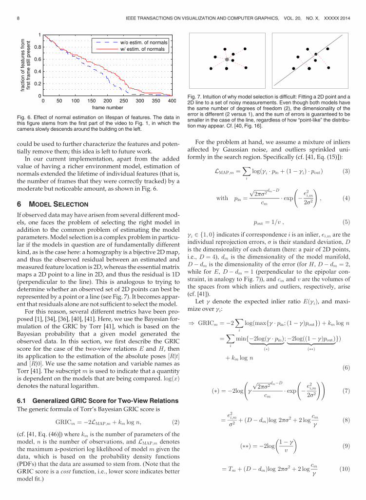
In our current implementation, apart from the addedvalue of having a richer environment model, estimation ofnormals extended the lifetime of individual features (that is,the number of frames that they were correctly tracked) by amoderate but noticeable amount, as shown in Fig. 6.
6 MODEL SELECTION
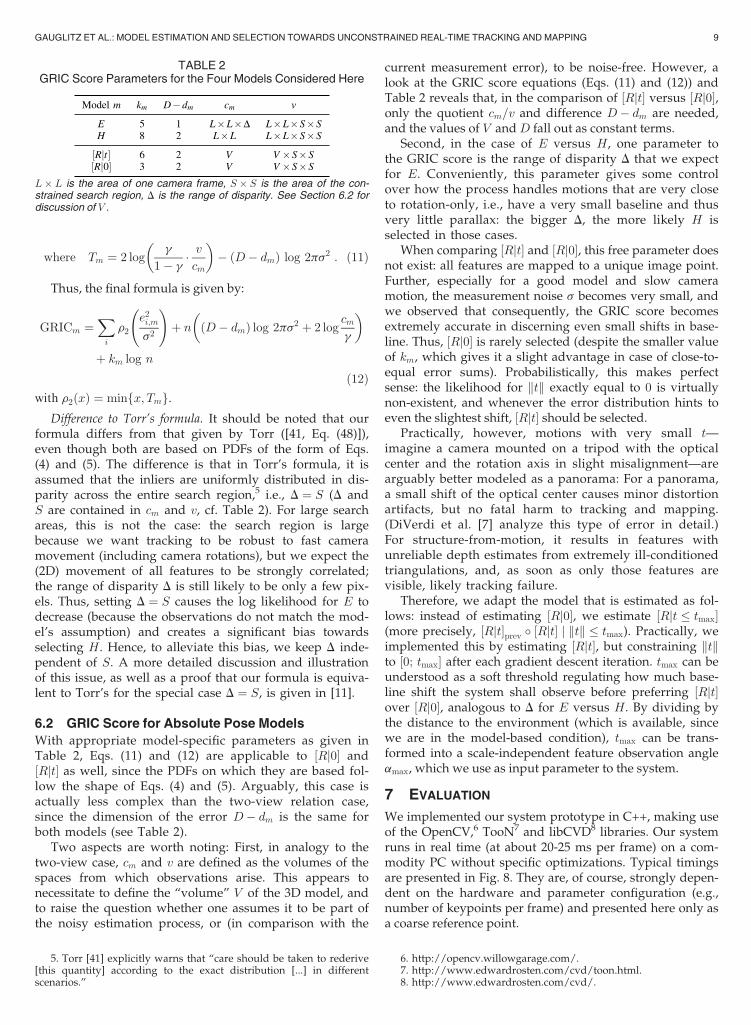
If observed data may have arisen from several different mod-els, one faces the problem of selecting the right model inaddition to the common problem of estimating the modelparameters. Model selection is a complex problem in particu-lar if the models in question are of fundamentally differentkind, as is the case here: a homography is a bijective 2D map,and thus the observed residual between an estimated andmeasured feature location is 2D, whereas the essential matrixmaps a 2D point to a line in 2D, and thus the residual is 1D(perpendicular to the line). This is analogous to trying todetermine whether an observed set of 2D points can best berepresented by a point or a line (see Fig. 7). It becomes appar-ent that residuals alone are not sufficient to select the model.
For this reason, several different metrics have been pro-posed [1], [34], [36], [40], [41]. Here, we use the Bayesian for-mulation of the GRIC by Torr [41], which is based on theBayesian probability that a given model generated theobserved data. In this section, we first describe the GRICscore for the case of the two-view relations E and H, thenits application to the estimation of the absolute poses ½Rjt�and ½Rj0�. We use the same notation and variable names asTorr [41]. The subscript m is used to indicate that a quantityis dependent on the models that are being compared. logðxÞdenotes the natural logarithm.
6.1 Generalized GRIC Score for Two-View Relations
The generic formula of Torr’s Bayesian GRIC score is
GRICm ¼ �2LMAP;m þ km log n; (2)
(cf. [41, Eq. (46)]) where km is the number of parameters of themodel, n is the number of observations, and LMAP;m denotesthe maximum a-posteriori log likelihood of model m given thedata, which is based on the probability density functions(PDFs) that the data are assumed to stem from. (Note that theGRIC score is a cost function, i.e., lower score indicates bettermodel fit.)
For the problem at hand, we assume a mixture of inliersaffected by Gaussian noise, and outliers sprinkled uni-formly in the search region. Specifically (cf. [41, Eq. (15)]):
LMAP;m ¼X
i
logðgi � pin þ ð1� giÞ � poutÞ (3)
with pin ¼ffiffiffiffiffiffiffiffiffiffi2ps2p dm�D
cm� exp �
e2i;m
2s2
!
; (4)
pout ¼ 1=v ; (5)
gi 2 f1; 0g indicates if correspondence i is an inlier, ei;m are theindividual reprojection errors, s is their standard deviation, Dis the dimensionality of each datum (here: a pair of 2D points,i.e., D ¼ 4), dm is the dimensionality of the model manifold,D� dm is the dimensionality of the error (for H, D� dm ¼ 2,while for E, D� dm ¼ 1 (perpendicular to the epipolar con-straint, in analogy to Fig. 7)), and cm and v are the volumes ofthe spaces from which inliers and outliers, respectively, arise(cf. [41]).
Let g denote the expected inlier ratio EðgiÞ, and maxi-mize over gi:
) GRICm ¼ �2X
i
logðmaxfg � pin; ð1� gÞpoutgÞ þ km log n
¼X
i
minf�2logðg � pinÞ|fflfflfflfflfflfflfflfflfflffl{zfflfflfflfflfflfflfflfflfflffl}ð�Þ
;�2logðð1� gÞpoutÞ|fflfflfflfflfflfflfflfflfflfflfflfflfflfflffl{zfflfflfflfflfflfflfflfflfflfflfflfflfflfflffl}ð��Þ
gÞ
þ km log n
(6)
ð�Þ ¼ �2log g
ffiffiffiffiffiffiffiffiffiffi2ps2p dm�D
cm� exp �
e2i;m
2s2
! !
(7)
¼e2i;m
s2þ ðD� dmÞlog 2ps2 þ 2 log
cmg
(8)
ð��Þ ¼ �2log1� g
v
� �(9)
¼ Tm þ ðD� dmÞlog 2ps2 þ 2 logcmg
(10)
Fig. 6. Effect of normal estimation on lifespan of features. The data inthis figure stems from the first part of the video to Fig. 1, in which thecamera slowly descends around the building on the left.
Fig. 7. Intuition of why model selection is difficult: Fitting a 2D point and a2D line to a set of noisy measurements. Even though both models havethe same number of degrees of freedom (2), the dimensionality of theerror is different (2 versus 1), and the sum of errors is guaranteed to besmaller in the case of the line, regardless of how “point-like” the distribu-tion may appear. Cf. [40, Fig. 16].
8 IEEE TRANSACTIONS ON VISUALIZATION AND COMPUTER GRAPHICS, VOL. 20, NO. X, XXXXX 2014
where Tm ¼ 2 logg
1� g� vcm
� �� ðD� dmÞ log 2ps2 : (11)
Thus, the final formula is given by:
GRICm ¼X
i
r2
e2i;m
s2
!
þ n ðD� dmÞ log 2ps2 þ 2 logcmg
� �
þ km log n
(12)
with r2ðxÞ ¼ minfx; Tmg.Difference to Torr’s formula. It should be noted that our
formula differs from that given by Torr ([41, Eq. (48)]),even though both are based on PDFs of the form of Eqs.(4) and (5). The difference is that in Torr’s formula, it isassumed that the inliers are uniformly distributed in dis-parity across the entire search region,5 i.e., D ¼ S (D andS are contained in cm and v, cf. Table 2). For large searchareas, this is not the case: the search region is largebecause we want tracking to be robust to fast cameramovement (including camera rotations), but we expect the(2D) movement of all features to be strongly correlated;the range of disparity D is still likely to be only a few pix-els. Thus, setting D ¼ S causes the log likelihood for E todecrease (because the observations do not match the mod-el’s assumption) and creates a significant bias towardsselecting H. Hence, to alleviate this bias, we keep D inde-pendent of S. A more detailed discussion and illustrationof this issue, as well as a proof that our formula is equiva-lent to Torr’s for the special case D ¼ S, is given in [11].
6.2 GRIC Score for Absolute Pose Models
With appropriate model-specific parameters as given inTable 2, Eqs. (11) and (12) are applicable to ½Rj0� and½Rjt� as well, since the PDFs on which they are based fol-low the shape of Eqs. (4) and (5). Arguably, this case isactually less complex than the two-view relation case,since the dimension of the error D� dm is the same forboth models (see Table 2).
Two aspects are worth noting: First, in analogy to thetwo-view case, cm and v are defined as the volumes of thespaces from which observations arise. This appears tonecessitate to define the “volume” V of the 3D model, andto raise the question whether one assumes it to be part ofthe noisy estimation process, or (in comparison with the
current measurement error), to be noise-free. However, alook at the GRIC score equations (Eqs. (11) and (12)) andTable 2 reveals that, in the comparison of ½Rjt� versus ½Rj0�,only the quotient cm=v and difference D� dm are needed,and the values of V and D fall out as constant terms.
Second, in the case of E versus H, one parameter tothe GRIC score is the range of disparity D that we expectfor E. Conveniently, this parameter gives some controlover how the process handles motions that are very closeto rotation-only, i.e., have a very small baseline and thusvery little parallax: the bigger D, the more likely H isselected in those cases.
When comparing ½Rjt� and ½Rj0�, this free parameter doesnot exist: all features are mapped to a unique image point.Further, especially for a good model and slow cameramotion, the measurement noise s becomes very small, andwe observed that consequently, the GRIC score becomesextremely accurate in discerning even small shifts in base-line. Thus, ½Rj0� is rarely selected (despite the smaller valueof km, which gives it a slight advantage in case of close-to-equal error sums). Probabilistically, this makes perfectsense: the likelihood for ktk exactly equal to 0 is virtuallynon-existent, and whenever the error distribution hints toeven the slightest shift, ½Rjt� should be selected.
Practically, however, motions with very small t—imagine a camera mounted on a tripod with the opticalcenter and the rotation axis in slight misalignment—arearguably better modeled as a panorama: For a panorama,a small shift of the optical center causes minor distortionartifacts, but no fatal harm to tracking and mapping.(DiVerdi et al. [7] analyze this type of error in detail.)For structure-from-motion, it results in features withunreliable depth estimates from extremely ill-conditionedtriangulations, and, as soon as only those features arevisible, likely tracking failure.
Therefore, we adapt the model that is estimated as fol-lows: instead of estimating ½Rj0�, we estimate ½Rjt tmax�(more precisely, ½Rjt�prev � ½Rjt� j ktk tmax). Practically, weimplemented this by estimating ½Rjt�, but constraining ktkto ½0; tmax� after each gradient descent iteration. tmax can beunderstood as a soft threshold regulating how much base-line shift the system shall observe before preferring ½Rjt�over ½Rj0�, analogous to D for E versus H. By dividing bythe distance to the environment (which is available, sincewe are in the model-based condition), tmax can be trans-formed into a scale-independent feature observation angleamax, which we use as input parameter to the system.
7 EVALUATION
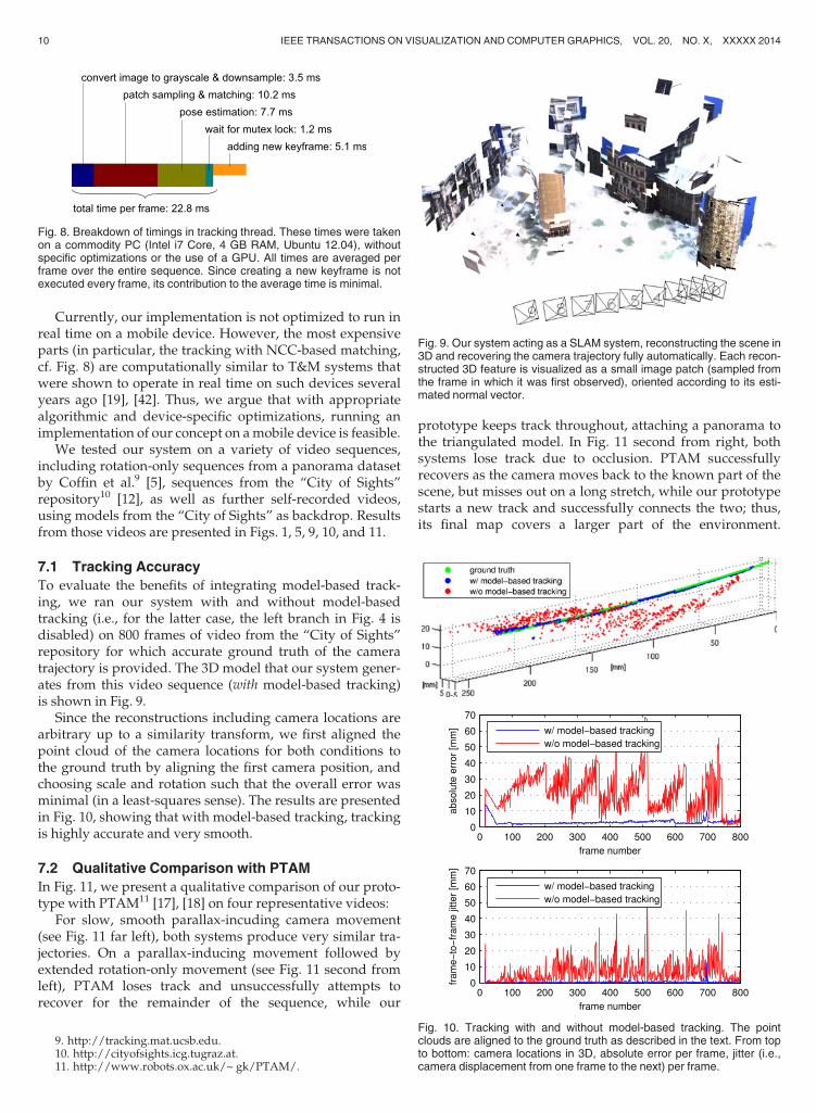
We implemented our system prototype in C++, making useof the OpenCV,6 TooN7 and libCVD8 libraries. Our systemruns in real time (at about 20-25 ms per frame) on a com-modity PC without specific optimizations. Typical timingsare presented in Fig. 8. They are, of course, strongly depen-dent on the hardware and parameter configuration (e.g.,number of keypoints per frame) and presented here only asa coarse reference point.
TABLE 2GRIC Score Parameters for the Four Models Considered Here
L� L is the area of one camera frame, S � S is the area of the con-strained search region, D is the range of disparity. See Section 6.2 fordiscussion of V .
5. Torr [41] explicitly warns that “care should be taken to rederive[this quantity] according to the exact distribution [...] in differentscenarios.”
6. http://opencv.willowgarage.com/.7. http://www.edwardrosten.com/cvd/toon.html.8. http://www.edwardrosten.com/cvd/.
GAUGLITZ ET AL.: MODEL ESTIMATION AND SELECTION TOWARDS UNCONSTRAINED REAL-TIME TRACKING AND MAPPING 9
Currently, our implementation is not optimized to run inreal time on a mobile device. However, the most expensiveparts (in particular, the tracking with NCC-based matching,cf. Fig. 8) are computationally similar to T&M systems thatwere shown to operate in real time on such devices severalyears ago [19], [42]. Thus, we argue that with appropriatealgorithmic and device-specific optimizations, running animplementation of our concept on a mobile device is feasible.
We tested our system on a variety of video sequences,including rotation-only sequences from a panorama datasetby Coffin et al.9 [5], sequences from the “City of Sights”repository10 [12], as well as further self-recorded videos,using models from the “City of Sights” as backdrop. Resultsfrom those videos are presented in Figs. 1, 5, 9, 10, and 11.
7.1 Tracking Accuracy
To evaluate the benefits of integrating model-based track-ing, we ran our system with and without model-basedtracking (i.e., for the latter case, the left branch in Fig. 4 isdisabled) on 800 frames of video from the “City of Sights”repository for which accurate ground truth of the cameratrajectory is provided. The 3D model that our system gener-ates from this video sequence (with model-based tracking)is shown in Fig. 9.
Since the reconstructions including camera locations arearbitrary up to a similarity transform, we first aligned thepoint cloud of the camera locations for both conditions tothe ground truth by aligning the first camera position, andchoosing scale and rotation such that the overall error wasminimal (in a least-squares sense). The results are presentedin Fig. 10, showing that with model-based tracking, trackingis highly accurate and very smooth.
7.2 Qualitative Comparison with PTAM
In Fig. 11, we present a qualitative comparison of our proto-type with PTAM11 [17], [18] on four representative videos:
For slow, smooth parallax-incuding camera movement(see Fig. 11 far left), both systems produce very similar tra-jectories. On a parallax-inducing movement followed byextended rotation-only movement (see Fig. 11 second fromleft), PTAM loses track and unsuccessfully attempts torecover for the remainder of the sequence, while our
prototype keeps track throughout, attaching a panorama tothe triangulated model. In Fig. 11 second from right, bothsystems lose track due to occlusion. PTAM successfullyrecovers as the camera moves back to the known part of thescene, but misses out on a long stretch, while our prototypestarts a new track and successfully connects the two; thus,its final map covers a larger part of the environment.
Fig. 8. Breakdown of timings in tracking thread. These times were takenon a commodity PC (Intel i7 Core, 4 GB RAM, Ubuntu 12.04), withoutspecific optimizations or the use of a GPU. All times are averaged perframe over the entire sequence. Since creating a new keyframe is notexecuted every frame, its contribution to the average time is minimal.
Fig. 9. Our system acting as a SLAM system, reconstructing the scene in3D and recovering the camera trajectory fully automatically. Each recon-structed 3D feature is visualized as a small image patch (sampled fromthe frame in which it was first observed), oriented according to its esti-mated normal vector.
Fig. 10. Tracking with and without model-based tracking. The pointclouds are aligned to the ground truth as described in the text. From topto bottom: camera locations in 3D, absolute error per frame, jitter (i.e.,camera displacement from one frame to the next) per frame.
9. http://tracking.mat.ucsb.edu.10. http://cityofsights.icg.tugraz.at.11. http://www.robots.ox.ac.uk/~ gk/PTAM/.
10 IEEE TRANSACTIONS ON VISUALIZATION AND COMPUTER GRAPHICS, VOL. 20, NO. X, XXXXX 2014
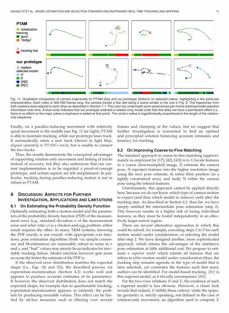
Finally, on a parallax-inducing movement with relativelyquick movement in the middle (see Fig. 11 far right), PTAMis able to maintain tracking, while our prototype loses track.It automatically starts a new track (shown in light blue,aligned separately to PTAM’s track), but is unable to connectthe two tracks.
Thus, the results demonstrate the conceptual advantagesof supporting rotation-only movement and linking of tracksinstead of recovery, but they also underscore that our cur-rent implementation is to be regarded a proof-of-conceptprototype, and certain aspects are left unoptimized. In par-ticular, tracking during parallax-inducing motion is not asrobust as PTAM.
8 DISCUSSION: ASPECTS FOR FURTHER
INVESTIGATION, APPLICATIONS AND LIMITATIONS
8.1 On Estimating the Probability Density Function
Optimally estimating both a motion model and the parame-ters of the probability density function (PDF) of the measure-ment error (e.g., standard deviation s of the measurementerror and inlier ratio g) is a chicken-and-egg problem: eitherresult requires the other. In many T&M systems, knowingthe PDF exactly is not crucial: with appropriate cost func-tions, pose estimation algorithms (both via sample consen-sus and M-estimators) are reasonably robust to noise in s
and g, and “bad” values may merely be an indicator for inev-itable tracking failure. Model selection however gets moreaccurate the better the estimate of the PDF is.
If the observed error distribution matches the expectedshape (i.e., Eqs. (4) and (5)), the described process viaexpectation-maximization (Section 4.2) works well andappears to produce accurate estimates of its parameters.If however the observed distribution does not match theexpected shape, for example due to questionable tracking,expectation-maximization appears to intensify the prob-lem by producing unusable values. This effect can be lim-ited by ad-hoc measures such as filtering over several
frames and clamping of the values, but we suggest thatfurther investigation is warranted to find an optimaland principled solution balancing accurate estimates andleniency for tracking.
8.2 On Improving Coarse-to-Fine Matching
The standard approach to coarse-to-fine matching (approxi-mately as employed by [17], [42], [43]) is to 1) locate featuresin a coarse (downsampled) image, 2) estimate the camerapose, 3) reproject features into the higher resolution imageusing the new pose estimate, 4) refine their position (in atightly constrained area), and lastly 5) refine the camerapose using the refined features.
Unfortunately, this approach cannot be applied directlyhere, because we do not know which type of camera motionto expect (and thus which model to enforce) until after thetracking step. As described in Section 4.1, thus far, we havesimply omitted the intermediate pose estimation (step 2).This however results in a higher risk of losing individualfeatures, as they must be found independently in an effec-tively larger search region.
There are several alternative approaches in which thiscould be solved, for example, executing steps 2 to 5 for eachmotion model under consideration, or selecting the modelafter step 2. We have designed another, more sophisticatedapproach, which retains the advantages of the interleavepose estimation at little additional cost: We propose to esti-mate a superset model which admits all features that areinliers to either motion model under consideration (thus, thetracking step remains agnostic to the type of model that islater selected), yet constrains the features such that manyoutliers can be identified. For model-based tracking, ½Rjt� isthis superset model, as it trivially encompasses ½Rj0�.
For the two-view relations H and E, the existence of sucha superset model is less obvious. However, a closer lookreveals that indeed, E fulfills these criteria: while the epipo-lar geometry is, strictly speaking, not defined in the case ofrotation-only movement, an algorithm used to compute E
Fig. 11. Qualitative comparison of camera trajectories for PTAM (top) and our prototype (bottom) on selected videos, highlighting a few particularcharacteristics. Each video is 300-500 frames long, the camera travels a few feet along a scene similar to the one in Fig. 9. The trajectories fromboth systems were aligned to each other as described in Section 7.1. The color bar underneath each panel shows per-frame tracking/model selectioninformation over time. A blue circle indicates that our prototype selected a rotation-only model (note that this does not have a permanent effect (i.e.,there is no effect on the map) unless a keyframe is added at that point). The circle’s radius is logarithmically proportional to the length of the rotation-only sequence.
GAUGLITZ ET AL.: MODEL ESTIMATION AND SELECTION TOWARDS UNCONSTRAINED REAL-TIME TRACKING AND MAPPING 11
will return some result �E, and true inliers for either H or E willfulfill xT2 � �E � x1 ¼ 0 (cf. in particular [14, Section 11.9.3]).Thus, while �E may lack a geometric interpretation (in thecase of rotation-only movement), it does provide a neces-sary condition for any correct correspondence. Assumingthat outliers are statistically independent, the chances for arandom outlier to satisfy xT2 � �E � x1 0 are small.
We have implemented and verified this approach on sev-eral videos (including rotation-only sequences, which, for�E, is the most unfavorable case). However, we have not yetintegrated it fully with the rest of our system, so the evalua-tion of potential robustness and performance improvementsremains to be done. One particular challenge is to robustlyestimate the PDF parameters (cf. Section 8.1) in the noweffectively much smaller active search regions.
8.3 On Merging of Maps
As discussed in Section 5.3, the algorithm we use to detectoverlap between disjoint tracks and thus initiate their merg-ing is basically the same as what is commonly employed forrelocalization, which implies that similar detection perfor-mance can be expected. An interesting area for futureresearch is to exploit the fact that we actually have moredata than what is available with the relocalization strategy:instead of one individual new frame, we have a new mapconsisting of multiple frames; thus, overlap detection couldpotentially yield higher detection performance than relocali-zation. This could be exploited even within the SBI-basedrecovery framework: For example, Kim et al. [16] haveexplored the use of “virtual keyframes,” i.e., renderings ofthe model from strategically distributed viewpoints, ratherthan actual keyframes. As we now seek to connect two mod-els, this strategy could be applied on both sides.
Similarly, the overlap between the tracks may encompassan area larger than a single frame. While we currently useonly features from one pair of keyframes to merge themaps, the registration could be improved by explicitly cal-culating and then using the entire extent of the overlap.Note however that a much larger overlap is unlikely, sinceotherwise it would likely have been detected earlier.
8.4 On Applications and Limitations of the HybridMap
It is clear that hybrid maps consisting of both SfM and pano-rama data (such as Fig. 1 or the map produced from Fig. 11second from left) do not possess all qualities that one wouldlook for in an ideal environment map. Most obviously, thepanorama part lacks depth information, but furthermore,the individual SfM reconstructions do not share a commonscale, since the rotation-only movement cannot propagatescale. We emphasize that this is not a limitation of ourdesign, but an inherent limitation of the input data; thealternative is not to create a fully 3D model, but to losetracking altogether. If a fully 3D model of the environmentis required, one has to either employ additional and/oractive sensors, or put constraints on the camera movement.
However, for many AR applications, where the mainpurpose of the model is to register annotations, the hybridnature of the map (and lack of depth) may not be a majorconcern, since the user automatically provides, and thus
allows registration of annotations for, exactly those view-points that are needed. Specifically, if only a panorama isprovided and thus an annotation can be registered to a bear-ing (but not depth) in this panorama, it implies that the userhas been looking at the scene from this viewpoint only andthus mainly needs the annotation’s bearing (cf. work onapplications of AR annotations based on panoramas [21],[42]). As soon as the user moves and thus the annotation’sdepth is needed for correct registration, this new viewpointcan be exploited to create 3D structure and register theannotation in 3D. Similarly, annotations in different parts ofthe scene may be registered to a different SfM group with adifferent scale factor, but these annotations are (by construc-tion) outside the user’s field of view and not visible directly.However, due to the topology provided by the hybrid map,topological or navigational annotations (for example, direc-tions towards an object outside the current field of view)can still be displayed, which is not possible with uncon-nected local reconstructions.
Further, even if one ultimately aims for a fully 3D model,it is arguably better to collect the panoramas than to discardthem. For example, Pan et al. [30] describe how to first col-lect panoramas, and then use them as single images withwide field of view for 3D reconstruction afterwards.
9 CONCLUSIONS
We have presented an approach and prototype implemen-tation for initialization-free real-time tracking and mappingthat supports both parallax-inducing and rotation-onlycamera motions in 3D environments, and integrates bothmodel-free and model-based tracking. Our design para-digm was to make use of all data that can be casually col-lected, and to not require any particular assistance by theuser (such as a separate initialization step, or particulartypes of camera motion).
Our system is able to track and map through motionsequences that neither conventional six-degree-of-freedomSLAM systems nor panoramic mapping systems can pro-cess. Depending on the video sequence, the strategy of start-ing a new track and later merging separate tracks (instead oftrying to relocalize with respect to the first map) can signifi-cantly increase the amount of data represented in the finalenvironment model.
We believe that our approach is an important conceptualstep towards the vision of fully transparent tracking andmapping for “Anywhere Augmentation” [15], making thebest use of the input data irrespective of the type of cameramotion (or, for example, the distance to the environment).We emphasize that our current implementation is to beregarded a proof-of-concept prototype, and many imple-mentation details are unoptimized. In particular, trackingrobustness during general motion is not yet comparable tosystems such as PTAM [17] or DTAM [27]. However, wehave shown that the core components of state-of-the-artSLAM systems—including model-based pose estimation,which is a significant advancement over our earlier imple-mentation [11]—can be integrated in a general framework(see Fig. 4) such that tracking and mapping can continuethrough both parallax-inducing and rotation-only motion.From here, techniques that were proven to increase
12 IEEE TRANSACTIONS ON VISUALIZATION AND COMPUTER GRAPHICS, VOL. 20, NO. X, XXXXX 2014
robustness or scalability—such as estimation of in-planerotation before the pose estimation [18], more advancedmap feature management including filtering of outliers,proactive search for new features in existing frames [17],and more sophisticated bundle adjustment strategies (cf.Section 5.2)—can be integrated as appropriate. Further areasfor future work were outlined in Section 8.
There are several other areas with open research ques-tions. For example, while we currently select only onemodel for the entire frame (which is, theoretically, the cor-rect thing to do, since the motion refers to the camera andthus to the entire frame), there may be cases especially inoutdoor scenes in which the foreground exhibits enoughparallax to be modeled in 3D, while the background exhibitslittle parallax and might benefit from the stable, dense map-ping that homographies offer. This leads to an interestingproblem in which image segmentation and environmentmodeling interact.
Finally, it remains an open question how a model thatconsists of a mixture of structural data and (partial) panora-mas can best be visualized, presented to, and navigated bythe user. This is not a concern if the model is used only asan anchor for AR annotations, in which case the user neveractually sees the model, but only the annotations fused withhis/her view of the real world (cf. discussion in Section 8.4).However, if the model is to be used in Virtual Reality aswell (for example, to allow a spatially remote user to viewthe scene [10]), the model itself needs to be visualized andnavigated. This works very well in the case of panoramicmapping, where the emerging model is easy to interpretand browse. It is inherently more challenging in the case of3D data (especially if the model is incomplete, so that theviewpoints for which useful views can be rendered arerestricted), and, to our knowledge, an open research prob-lem for the case of live, incomplete data that consists of mix-tures of structural and panoramic data. By building on largedata collections and offline reconstructions, interestingviewing modalities for mixed data like this have emergedfrom the SfM community [38].
ACKNOWLEDGMENTS
The authors would like to thank their anonymousreviewers for many acute observations and suggestions,and several attendees of ISMAR 2012 for insightful discus-sions, especially Gerhard Reitmayr, Daniel Wagner, PierreFite-Georgel, Andrew Davison, Georg Klein, and TomDrummond. This work was supported by a Chancellor’sfellowship from UCSB for S.G., NSF CAREER Grant IIS-0747520, ONR Grant N00014-09-1-1113, and NSF GrantIIS-1219261.
REFERENCES
[1] H. Akaike, “A New Look at the Statistical Model Identification,”IEEE Trans. Automatic Control, vol. 19, no. 6, pp. 716-723, Dec.1974.
[2] S. Baker and I. Matthews, “Lucas-Kanade 20 Years on: A UnifyingFramework: Part 1,” Technical Report CMU-RI-TR-02-16, RoboticsInst., Carnegie Mellon Univ., July 2002.
[3] J. Civera, A. Davison, and J. Montiel, “Inverse Depth Parametriza-tion for Monocular SLAM,” IEEE Trans. Robotics, vol. 24, no. 5,pp. 932-945, Oct. 2008.
[4] J. Civera, A. Davison, and J. Montiel, “Interacting Multiple ModelMonocular SLAM,” Proc. IEEE Int’l Conf. Robotics and Automation(ICRA), pp. 3704-3709, 2008.
[5] C. Coffin, J. Ventura, and T. H€ollerer, “A Repository for theEvaluation of Image-Based Orientation Tracking Solutions,”Proc. Second Int’l TrakMark Workshop in Conjunction withISMAR 2011, 2011.
[6] A.J. Davison, I.D. Reid, N.D. Molton, and O. Stasse, “MonoSLAM:Real-Time Single Camera SLAM,” IEEE Trans. Pattern Analysis andMachine Intelligence, vol. 29, no. 6, pp. 1052-1067, June 2007.
[7] S. DiVerdi, J. Wither, and T. H€ollerer, “All Around the Map:Online Spherical Panorama Construction,” Computers andGraphics, vol. 33, no. 1, pp. 73-84, 2009.
[8] E. Eade and T. Drummond, “Unified Loop Closing and Recoveryfor Real Time Monocular SLAM,” Proc. British Machine VisionConf. (BMVC), 2008.
[9] S. Gauglitz, L. Foschini, M. Turk, and T. H€ollerer, “EfficientlySelecting Spatially Distributed Keypoints for Visual Tracking,”Proc. IEEE Int’l Conf. Image Processing (ICIP), 2011.
[10] S. Gauglitz, C. Lee, M. Turk, and T. H€ollerer, “Integrating thePhysical Environment into Mobile Remote Collaboration,” Proc.14th Int’l Conf. Human-Computer Interaction with Mobile Devices andServices (MobileHCI), 2012.
[11] S. Gauglitz, C. Sweeney, J. Ventura, M. Turk, and T. H€ollerer,“Live Tracking and Mapping from Both General and Rotation-Only Camera Motion,” Proc. IEEE Int’l Symp. Mixed and AugmentedReality (ISMAR), 2012.
[12] L. Gruber, S. Gauglitz, J. Ventura, S. Zollmann, M. Huber, M.Schlegel, G. Klinker, D. Schmalstieg, and T. H€ollerer, “The City ofSights: Design, Construction, and Measurement of an AugmentedReality Stage Set,” Proc. IEEE Ninth Int’l Symp. Mixed and Aug-mented Reality (ISMAR), pp. 157-163, Oct. 2010.
[13] L. Gruber, S. Zollmann, D. Wagner, D. Schmalstieg, and T.H€ollerer, “Optimization of Target Objects for Natural FeatureTracking,” Proc. 20th Int’l Conf. Pattern Recognition (ICPR),pp. 3607-3610, 2010.
[14] R. Hartley and A. Zisserman, Multiple View Geometry in ComputerVision. second ed., Cambridge Univ. Press, 2004.
[15] T. H€ollerer, J. Wither, and S. DiVerdi, “Anywhere Augmentation:Towards Mobile Augmented Reality in Unprepared Environ-ments,” Location Based Services and TeleCartography, Series: LectureNotes in Geoinformation and Cartography, pp. 393-416, Springer-Verlag, Feb. 2007.
[16] S. Kim, C. Coffin, and T. H€ollerer, “Relocalization Using VirtualKeyframes for Online Environment Map Construction,” Proc. 16thACM Symp. Virtual Reality Software and Technology (VRST),pp. 127-134, 2009.
[17] G. Klein and D. Murray, “Parallel Tracking and Mapping forSmall AR Workspaces,” Proc. IEEE and ACM Sixth Int’l Symp.Mixed and Augmented Reality (ISMAR), 2007.
[18] G. Klein and D. Murray, “Improving the Agility of Keyframe-Based SLAM,” Proc. 10th European Conf. Computer Vision (ECCV),pp. 802-815, Oct. 2008.
[19] G. Klein and D. Murray, “Parallel Tracking and Mapping on aCamera Phone,” Proc. IEEE Eighth Int’l Symp. Mixed and Aug-mented Reality, pp. 83-86, Oct. 2009.
[20] M. Klopschitz, A. Irschara, G. Reitmayr, and D. Schmalstieg,“Robust Incremental Structure from Motion,” Proc. Int’l Symp. 3DData Processing, Visualization and Transmission (3DPVT), vol. 2, p. ,2010.
[21] T. Langlotz, C. Degendorfer, A. Mulloni, G. Schall, G. Reitmayr,and D. Schmalstieg, “Robust Detection and Tracking of Annota-tions for Outdoor Augmented Reality Browsing,” Computers andGraphics, vol. 35, no. 4, pp. 831-840, 2011.
[22] S. Lieberknecht, A. Huber, S. Ilic, and S. Benhimane, “RGB-DCamera-Based Parallel Tracking and Meshing,” Proc. IEEE Int’lSymp. Mixed and Augmented Reality (ISMAR), pp. 147-155, Oct.2011.
[23] M.A. Lourakis and A. Argyros, “SBA: A Software Package forGeneric Sparse Bundle Adjustment,” ACM Trans. Math. Software,vol. 36, no. 1, pp. 1-30, 2009.
[24] S. Lovegrove and A.J. Davison, “Real-Time Spherical MosaicingUsing Whole Image Alignment,” Proc. European Conf. ComputerVision (ECCV), vol. 6313, pp. 73-86, 2010.
[25] N. Molton, A. Davison, and I. Reid, “Locally Planar Patch Featuresfor Real-Time Structure from Motion,” Proc. 15th British MachineVision Conf. (BMVC), 2004.
GAUGLITZ ET AL.: MODEL ESTIMATION AND SELECTION TOWARDS UNCONSTRAINED REAL-TIME TRACKING AND MAPPING 13
[26] E. Mouragnon, M. Lhuillier, M. Dhome, F. Dekeyser, and P. Sayd,“Real Time Localization and 3D Reconstruction,” Proc. IEEE Com-puter Vision and Pattern Recognition (CVPR), vol. 1, pp. 363-370,2006.
[27] R. Newcombe, S. Lovegrove, and A. Davison, “DTAM: DenseTracking and Mapping in Real-Time,” Proc. IEEE Int’l Conf. Com-puter Vision (ICCV), pp. 2320-2327, 2011.
[28] R.A. Newcombe, S. Izadi, O. Hilliges, D. Molyneaux, D. Kim, A.J.Davison, P. Kohli, J. Shotton, S. Hodges, and A. Fitzgibbon,“KinectFusion: Real-time Dense Surface Mapping and Tracking,”Proc. IEEE Int’l Symp. Mixed and Augmented Reality (ISMAR), 2011.
[29] D. Nist�er, “An Efficient Solution to the Five-Point Relative PoseProblem,” IEEE Trans. Pattern Analysis and Machine Intelligence,vol. 26, no. 6, pp. 756-770, June 2004.
[30] Q. Pan, C. Arth, G. Reitmayr, E. Rosten, and T. Drummond,“Rapid Scene Reconstruction on Mobile Phones from PanoramicImages,” Proc. IEEE 10th Int’l Symp. Mixed and Augmented Reality(ISMAR), pp. 55-64, 2011.
[31] C. Pirchheim and G. Reitmayr, “Homography-Based Planar Map-ping and Tracking for Mobile Phones,” Proc. IEEE Int’l Symp.Mixed and Augmented Reality (ISMAR), pp. 27-36, 2011.
[32] M. Pollefeys, F. Verbiest, and L. Van Gool, “Surviving DominantPlanes in Uncalibrated Structure and Motion Recovery,” Proc.European Conf. Computer Vision (ECCV), pp. 613-614, 2002.
[33] J. Repko and M. Pollefeys, “3D Models from Extended Uncali-brated Video Sequences: Addressing Key-Frame Selection andProjective Drift,” Proc. Fifth Int’l Conf. 3D Digital Imaging andModeling (3DIM), pp. 150-157, 2005.
[34] J. Rissanen, “Modeling by Shortest Data Description,” Automatica,vol. 14, no. 5, pp. 465-471, 1978.
[35] E. Rosten and T. Drummond, “Machine Learning for High-SpeedCorner Detection,” Proc. IEEE European Conf. Computer Vision,vol. 1, pp. 430-443, May 2006.
[36] G. Schwarz, “Estimating the Dimension of a Model,” Annals of Sta-tistics, vol. 6, pp. 461-464, 1978.
[37] J. Shi and C. Tomasi, “Good Features to Track,” Proc. IEEE Conf.Computer Vision and Pattern Recognition, pp. 593-600, 1994.
[38] N. Snavely, S. Seitz, and R. Szeliski, “Photo Tourism: ExploringPhoto Collections in 3D,” ACM Trans. Graphics, vol. 25, no. 3,pp. 835-846, 2006.
[39] H. Strasdat, J. Montiel, and A. Davison, “Real-Time MonocularSLAM: Why Filter?” Proc. IEEE Int’l Conf. Robotics and Automation(ICRA), pp. 2657-2664, 2010.
[40] P.H. Torr, A.W. Fitzgibbon, and A. Zisserman, “The Problem ofDegeneracy in Structure and Motion Recovery from UncalibratedImage Sequences,” Int’l J. Computer Vision, vol. 32, pp. 27-44, 1999.
[41] P. Torr, “Bayesian Model Estimation and Selection for EpipolarGeometry and Generic Manifold Fitting,” Int’l J. Computer Vision,vol. 50, no. 1, pp. 35-61, 2002.
[42] D. Wagner, A. Mulloni, T. Langlotz, and D. Schmalstieg, “Real-Time Panoramic Mapping and Tracking on Mobile Phones,” Proc.IEEE Virtual Reality (VR), Mar. 2010.
[43] D. Wagner, D. Schmalstieg, and H. Bischof, “Multiple TargetDetection and Tracking with Guaranteed Framerates on MobilePhones,” Proc. IEEE Int’l Symp. Mixed and Augmented Reality(ISMAR ’09), pp. 57-64, 2009.
[44] H. Wuest, F. Wientapper, and D. Stricker, “Acquisition of HighQuality Planar Patch Features,” Proc. Fourth Int’l Symp. Advancesin Visual Computing, pp. 530-539, 2008.
Steffen Gauglitz received the Dipl.-Ing. degreein computer engineering from RWTH AachenUniversity, Germany, in 2008. He is currentlyworking toward the PhD degree in computer sci-ence at the University of California, Santa Bar-bara. His current research interests includeaugmented reality, real-time computer vision,and in particular their application to interactiveand immersive telepresence. He is the recipientof a UCSB Chancellor’s Fellowship and hasinterned at WorldViz LLC, Qualcomm Inc.
CR&D, and Google Inc. He is a student member of the IEEE.
Chris Sweeney received the BS and BA degreesin computer science and mathematics from theUniversity of Virginia in 2011. He is currentlyworking toward the PhD degree in computer sci-ence in the Four Eyes Lab at the University ofCalifornia, Santa Barbara. His research interestsinclude bridging the gap between large-scalestructure from motion and traditional SLAM sys-tems so that large 3D reconstructions can beeasily accessible for outdoor augmented reality.He is currently supported by a US National Sci-
ence Foundation Graduate Research Fellowship. He is a student mem-ber of the IEEE.
Jonathan Ventura received the BS, MS andPhD degrees from the University of California,Santa Barbara, in 2001, 2005, and 2012, respec-tively. He has worked as a project scientist atUCSB and as an intern at the Adobe AdvancedTechnology Lab in San Jose, California. In hisdoctoral dissertation, he developed methods forindividual users to visually model and track out-door buildings with mobile phone hardware. He iscurrently a senior researcher at the Institute forComputer Graphics and Vision at Graz University
of Technology in Austria. His current research interests include com-puter vision technologies, user interfaces and application design forwide-area augmented reality. He is a member of the IEEE.
Matthew Turk received the BS degree fromVirginia Tech, Blacksburg, the MS degreefrom Carnegie Mellon University, Pittsburgh,Pennsylvania, and the PhD degree from theMassachusetts Institute of Technology, Cam-bridge. He is a professor of computer scienceand was a former chair of Media Arts andTechnology at the University of California,Santa Barbara, where he co-directs the FourEyes Lab and is involved in several interdisci-plinary centers and programs. He has worked
at Martin Marietta Denver Aerospace, LIFIA/ENSIMAG (Grenoble,France), Teleos Research, and Microsoft Research, where he was afounding member of the Vision Technology Group. He is on the edi-torial board of the ACM Transactions on Intelligent Interactive Sys-tems and the Journal of Image and Vision Computing. He is a fellowof the IEEE and the 2011-2012 Fulbright-Nokia distinguished chairin Information and Communications Technologies.
Tobias H€ollerer received the graduate degreein informatics from the Technical University ofBerlin, Germany, and the MS and PhD degreesin computer science from Columbia University,City of New York. He is a professor of computerscience at the University of California, Santa Bar-bara, where he co-directs the Four Eyes Lab,conducting research in the four I’s of Imaging,Interaction, and Innovative Interfaces. Hisresearch interests include the area of human-computer interaction and experimental systems,
with a particular focus on augmented and virtual reality, information visu-alization, 3D displays and interaction, and social and adaptive user inter-faces. He is a recipient of the National Science Foundation’s CAREERaward, for his work on “Anywhere Augmentation”, which enables mobilecomputer users to place annotations in 3D space wherever they go. Heis a member of the IEEE.
" For more information on this or any other computing topic,please visit our Digital Library at www.computer.org/publications/dlib.
14 IEEE TRANSACTIONS ON VISUALIZATION AND COMPUTER GRAPHICS, VOL. 20, NO. X, XXXXX 2014

![World-Stabilized Annotations and Virtual Scene Navigation ...holl/pubs/Gauglitz-2014-UIST.pdf · structed environment (“VR view”). Lastly, Sukan et al. [40] ... device hardware](https://img.pdfslide.net/doc/110x75/5fe4a662e792820d95490638/world-stabilized-annotations-and-virtual-scene-navigation-hollpubsgauglitz-2014-uistpdf.jpg)


![In Touch with the Remote World: Remote Collaboration with ...holl/pubs/Gauglitz-2014-VRST.pdf · Christie and Olivier 2009; Jankowski and Hachet 2013], including ... The feedback](https://img.pdfslide.net/doc/110x75/5fcf1dca5defdb782b7a611c/in-touch-with-the-remote-world-remote-collaboration-with-hollpubsgauglitz-2014-vrstpdf.jpg)