Embed Size (px)
Citation preview

IFC-COMPLIANT DESIGN INFORMATION MODELING AND SHARING
SUBMITTED: September 2002 REVISED: April 2003 PUBLISHED: May 2003 at http://www.itcon.org/2003/1 EDITOR: Bo-Christer Bjork
QZ Yang, Dr Singapore Institute of Manufacturing Technology, Singapore
r.edu.sg/ email: [email protected], http://www.simtech.a-sta
SUMMARY: This paper presents a method for IFC-compliant design information modelling and sharing by use of the IFC technology and IFC property set (Pset) extension mechanism. The method comprises defining the non-standard and project-specific design information in extensible and interoperable Psets, instantiating these Pset definitions with CAD object information and generating IFC-compliant product models, and managing and sharing product model data across AEC computer applications. A software implementation of the method has been developed as an add-on toolkit to the Architectural Desktop CAD package and incorporated into a Web-enabled information service prototype system. The prototype supports the generation of extended IFC product models from architectural design, manages the consistency and sharability of the IFC and XML objects in the system repository, and facilitates the design information exchange and sharing among different software systems. Three use scenarios of the prototype are discussed in the paper for CAD information modelling with Pset extensions, IFC and XML objects query and browsing over the Internet, and XML-based information exchange and sharing from architectural design to quantity survey and to structural analysis applications.
KEYWORDS: Design information modelling, interoperability, IFC object model, Pset extensions, data exchange and sharing.
1. INTRODUCTION Modelling of interoperable information in computer-aided architectural design involves not only the representation of full geometry of building objects, but also the formalisation of all other non-graphical and project-related information, with standardised definitions for common semantics of design concept. Such a common data model forms the basis for exchange and sharing of the interoperable design information across different product life-cycle software applications in building design, analysis, procurement, construction, and facility management. On the other hand, the common data model has to be extensible and flexible to cater for the potentially unique information requirements from project to project. The Industry Foundation Class (IFC) technology (IAI, 2000) provides mechanisms for the uniform representation and exchange of project information to facilitate the software interoperability. It also specifies approaches for extending the IFC object model. Among others, the IFC Property Set (Pset) is known as a mechanism for dynamic definition extension of the standard IFC model (IAI, 2001).
Substantial efforts have been made to continuously develop the IFC object models (IAI, 1998, 1999 and 2000) and to promote the IFC-based software applications to the AEC/FM industry. Especially in the architectural CAD area, commercial IFC solutions have been or are being made available to CAD users and to other software applications. For example, the leading architectural CAD packages, such as Architectural Desktop (ADT) (Autodesk, 2001), ArchiCAD (Graphisoft, 2002), Microstation TriForma (Bentley System, 2002), and AllPlan (Nemetschek, 2002), are currently providing/developing facilities to support the IFC format in architectural and structural design. Another active implementation area is in the development of the IFC toolboxes as underlying IFC information supporting platforms for storage, management, exchange and sharing of IFC product model data. The EDM package (EPM Technology, 2002) provides full set of APIs for processing IFC and XML objects with Web support. The IFC Toolboxes from Eurostep (Eurostepsys, 2002a) and PDTec (PDTec, 2002) also facilitate the IFC object reading, writing, and accessing from other software applications. Besides these CAD and toolbox implementations, many other pilot IFC projects in specific AEC application domains, such as in building energy simulation (Hitchcock, 2000), construction planning (YIT, 2002), code compliance checking (Yang and
ITcon Vol. 8 (2003); Yang, pg. 1
Li, 2001, Han el al, 1998), and project management for cost estimation and scheduling (Froese el al, 1999) have also been conducted.
Although these IFC development and implementation efforts have generated critical impacts on the conventional ways of representing and exchanging application-specific information between AEC/FM software systems, the IFC object model has not achieved widespread adoption on a general level in the industry (Stouffs and Krishnamurti, 2001). Furthermore, most of these implementations are based on the standard IFC object models with only formal and static definitions for generalised concepts.
The methods and software implementations of the IFC Pset extension mechanism on commercial CAD platforms are required in the real-world projects for generation of extended IFC models with both the IFC-defined and user-defined design properties to satisfy the specific information needs from different disciplinary software applications. But currently, such implementations in the commercial CAD packages, such as in the ADT system, are not available. To address the information sharing capabilities in IFC, traditionally they are implemented through common project databases, which can provide sharable information content compliant with the IFC object model to satisfy the information needs from multi-users and multi-applications; maintain the data integrity and consistency; and manage the concurrent accessibility to shared data from each user/application. However these information sharing capabilities of the static database implementations are inadequate for the information sharing needs identified in the present research, where the multi-disciplinary design teams (architects, structural engineers, and quantity surveyors) are sharing variety of non-standard information with localised context (PSB, 2001) in their collaborative design activities. Most of the project-specific information is defined and stored in each proprietary system, but needs to be shared within the project team. As such, the current research emphasis will be both on developing IFC-based common project databases and on defining and implementing sharable interaction protocols used for information exchange and sharing.
This paper describes a method to develop IFC-compliant information models for 3D architectural design by use of the IFC technology and IFC Pset extension mechanism. It also implements a Web-enabled information service prototype to support the generation of the extended IFC product models from architectural design by ADT, to manage the consistency and sharability of the IFC and XML objects in the prototype repository, and to facilitate the design information exchange and sharing between AEC applications. The client-side application of the prototype is developed as an add-on toolkit to the ADT CAD package. It is used for IFC-compliant information modelling with Pset extensions embedded in the ADT CAD models and populated in the IFC data files. The server-side application of the prototype is developed on top of the WebSTEP server (Eurostepsys, 2002b) and used to provide Web-based services for IFC-compliant information management, exchange and sharing.
The paper is organised into five sections. Section 2 proposes a method for the extended IFC information modelling on the ADT CAD platform. Section 3 describes the prototype implementation of this method. Section 4 discusses the use scenarios of the prototype. Section 5 outlines the conclusion of this research and its future development.
2. IFC-COMPLIANT DESIGN INFORMATION MODELLING A method for modelling richer sets of design information on ADT CAD platform by using IFC Pset extension mechanism is described in this section, including ADT property modelling, association between properties and CAD models, property mapping from ADT to IFC definitions, and common vocabulary database and property database establishment and management.
2.1 ADT Property Modelling An IFC-compliant design object model consists of not only standard representations of the design objects, object relationships and constraints defined in the specification of the IFC object model (IAI, 2000), but also semantic instantiations from the Pset dynamic definition extensions specified by projects. Containing richer information sets pertaining to a design, such a model is capable of supporting the different information needs from different design disciplines. The design characteristics can be extracted from the object model and transformed for use in other discipline-specific computer applications. As such, the model objects, especially the extended property objects have to be defined with unambiguous and consistent definitions across different disciplinary software applications. That’s why a well-structured information modelling method is needed to define these Pset extensions for architectural design objects.
ITcon Vol. 8 (2003); Yang, pg. 2

A basic concept for describing ADT property extensions is that of entity property. An ADT entity property is defined by attributes and quantitative constraints of attributes. An attribute has a name for identifying the attribute and a data type for indicating the data format of the attribute value. All attributes of an entity property together describe the semantics of the property being defined. A quantitative constraint contains a set of methods to control the validity of the attribute types and values which ADT system can support. An ADT property object is instantiated by using an entity property as a template. During instantiation, the quantitative constraints of the entity property will not be presented in the property objects generated. Instead, they are implemented as constraint algorithms in the software add-on tool of ADT and associated with the respective attributes in this entity property. Whenever a property object is instantiated by assigning attribute values to the attribute names of this entity property, these quantitative constraint algorithms will be invoked to ensure the auto-extracted or user-entered attribute types and values compliant with the data type and data scope defined in the entity property for these attributes. Table 1 shows an example of modelling an ADT entity property for fire rating and some of the fire rating property objects instantiated.
TABLE 1: Modelling of ADT FireRating entity property and its instances
Attributes
Name DataType Quantitative Constraints
PropertyName String
Description String
Value Real >= 0
Unit TimeUnit Enum (Hour, Minute)
Instantiation
Property Name Description Value Unit
FireRating 1 Fire rating of entrance door 2.5 Hour
FireRating 2 Fire rating of window 1 0.5 Hour
FireRating 3 Fire rating of roof assembly 75 Minute
2.2 Association between Properties and CAD Models The ADT entity properties are categorised as groups called ADT Property Sets (ADT Pset). Similar to the concept of IFC Pset, an ADT Pset is a container to hold collections of properties and used to facilitate more flexible and easier association between ADT design objects and groups of properties. An ADT Pset is associated with one or more ADT CAD objects. This association is established in the ADT modelling environment by direct linkage relations between the ADT Pset and CAD object(s). Fig. 1 illustrates the modelling of ADT Pset and the association between Psets and ADT CAD models.
ITcon Vol. 8 (2003); Yang, pg. 3
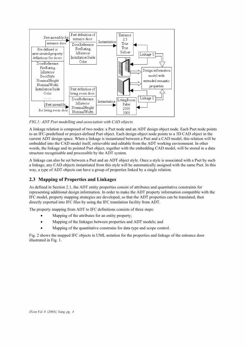
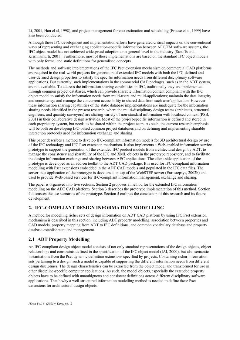
FIG.1: ADT Pset modelling and association with CAD objects
A linkage relation is composed of two nodes: a Pset node and an ADT design object node. Each Pset node points to an IFC-predefined or project-defined Pset object. Each design object node points to a 3D CAD object in the current ADT design space. When a linkage is instantiated between a Pset and a CAD model, this relation will be embedded into the CAD model itself, retrievable and editable from the ADT working environment. In other words, the linkage and its pointed Pset object, together with the embedding CAD model, will be stored in a data structure recognisable and processible by the ADT system.
A linkage can also be set between a Pset and an ADT object style. Once a style is associated with a Pset by such a linkage, any CAD objects instantiated from this style will be automatically assigned with the same Pset. In this way, a type of ADT objects can have a group of properties linked by a single relation.
2.3 Mapping of Properties and Linkages As defined in Section 2.1, the ADT entity properties consist of attributes and quantitative constraints for representing additional design information. In order to make the ADT property information compatible with the IFC model, property mapping strategies are developed, so that the ADT properties can be translated, then directly exported into IFC files by using the IFC translation facility from ADT.
The property mapping from ADT to IFC definitions consists of three steps: • Mapping of the attributes for an entity property; • Mapping of the linkages between properties and ADT models; and • Mapping of the quantitative constrains for data type and scope control.
Fig. 2 shows the mapped IFC objects in UML notation for the properties and linkage of the entrance door illustrated in Fig. 1.
ITcon Vol. 8 (2003); Yang, pg. 4

#10 (Pset of door) : IfcPropertySet
- Descript ion : IfcText = Pset of entrance door- GlobalId : IfcGloballyUniqueId = grRA6z6jQe- HasProperties : IfcProperty = (#11, #12, #13, #14, #15)- Name : IfcLabel = Pset_DoorCommon- OwnerHistory : IfcOwnerHistory = #60
#11 (Type of door) : IfcPropertyEnumeratedValue
- Descript ion : IfcText = Type of door- Enumerat ionReference : IfcPropertyEnumeration = #50- EnumerationValues : IfcValue = Entrance- Name : IfcIdentifier = DoorReference
#50 (Door type enumeration) : IfcPropertyEnumeration
- Enumerat ionValues : IfcValue = (Kitchen, BedRoom, Entrance)- Name : IfcLabel = DoorTypeEnum- Unit : IfcUnit = $
#14 (Instal lation guide) : IfcPropertySingleValue
- Description : IfcText = $- Name : IfcIdentifier = InstallationGuide- NominalValue : IfcValue = True- Unit : IfcUnit = $
#15 (Door color) : IfcPropertySingleValue
- Descript ion : IfcText = color of entrance door- Name : IfcIdentifier = Color- NominalValue : IfcValue = Yellow- Unit : IfcUnit = $
#60 (Owner history) : IfcOwnerHistory
#1 (Linkage) : IfcRelDefinesByPropert ies
- Description : IfcText = $- GlobalId : IfcGloballyUniqueId = 0hsdEiU8fg- Name : IfcLabel = $- OwnerHistory : IfcOwnerHistory = #60- RelatedObjects : IfcObject = (#20)- RelatingPropertyDefinition : IfcPropertySetDefini tion = #10
#12 (Fire rating of door) : IfcPropertySingleValue
- Description : IfcText = Fire rating for entrance door- Name : IfcIdentifi er = Fi reRating- NominalValue : IfcValue = 2.5- Unit : IfcUni t = Hour
#13 (External door) : IfcPropertySingleValue
- Description : IfcText = $- Name : IfcIdentifier = IsExterior- NominalValue : IfcValue = True- Unit : IfcUni t = $
#20 (Ent rance door) : IfcDoor
Utility : QuantitativeConstraint
mapType( )veri fyType( )verifyScope( )
mapType( )veri fyType( )
veri fyType( )
veri fyType( )
verifyType( )
FIG.2: UML collaboration diagram of mapped IFC objects for a door Pset object and its linkage
2.4 Common Vocabulary A collection of common vocabulary agreed by multi-disciplinary design teams in a collaborative project would be beneficial in achieving a common and explicit naming approach to shared property definitions. By complying with the vocabulary, much of misunderstanding and misinterpretation to the shared information would be removed. Furthermore, use of common vocabulary would ensure more effective and consistent manipulations to shared property definitions in property database in Section 2.5.
It is concerned in this research how to define and maintain a common vocabulary database, rather than how to establish the meaning of terms in the vocabulary, or how to make everyone agree with the terms and the like. A vocabulary database stores groups of common-agreed and sharable terms together with their meanings used in collaborative design processes for naming Psets and inclusion properties, naming CAD type objects (styles), and naming geometric representation maps of CAD models. A data structure in XML is defined to store and retrieve the vocabulary entries, which comprises:
• a structured storage hierarchy for vocabulary;
• a Pset field for vocabulary of Pset names;
• a collection of property names classified under a Pset name;
• a type object field for vocabulary of CAD style names; and
• a collection of representation map names classified under a type object.
ITcon Vol. 8 (2003); Yang, pg. 5

The IFC pre-defined Pset and property names are included in the vocabulary database. The other non-standard terms/names defined in the common vocabulary are compliant with the CP83 CAD standard of Singapore (PSB, 2001). The vocabulary database is stored in the server repository and sharable among multi-disciplinary design teams. It is extensible and customisable to meet the project-specific naming requirements, but this has to be done through a vocabulary database administrator on request. The basic manipulations including search, retrieval, validation and updating to the vocabulary database are supported.
2.5 Property Database In this research, a property database is modelled to store and manage the pre-defined and new-created property and Pset definitions in the XML format for ADT. Instead of using tabular forms to hold these definitions in the database, XML files are employed to maximise the information structuring flexibility, property definition accessibility, and property information exchangability across applications. The property database is composed of XML documents. Each XML file defines one Pset with a collection of properties. The information structure of each XML document is described in DTD (Ahmed et al, 2001). Default DTDs for Pset definitions of ADT objects and ADT type objects have been provided with the ADT add-on toolkit as templates. Alternatively, a well-formed Pset XML is also acceptable to the database.
A rich set of pre-defined properties built from IFC recommended property definitions and extended with localised CAD standard content has been specified, stored and managed by the property database. Meanwhile, ADT add-on facilities are provided for new properties creation or for existing properties modification. The common vocabulary in Section 2.4 has been incorporated into these facilities to enforce use of the standard terms and names in property creation and modification. In the current implementation, the property database provides the functionality of:
• receiving Pset and property definitions in XML;
• validating the attribute identifiers of each definition for compliance with the common vocabulary;
• accepting and storing the valid XML files in the database;
• searching and comparing XML files in question; and
• providing operational methods to manipulate the property database entries.
All XML elements in the property database are maintained by the ADT add-on toolkit for retrieval, modification, deletion, and adding operations. The tool also supports for searching and loading the user-specified Psets in the database to an ADT CAD drawing database once a linkage between the Pset and the CAD model having been established.
3. FROM INFORMATION MODELLING TO SOFTWARE IMPLEMENTATION To take advantage of the extended design information modelling method in practice, a software implementation of the method is required. The development of a prototype to test the modelling concepts and the interoperability of the extended IFC models is discussed in this section.
3.1 Functional Architecture The prototype is developed as a three-tier Web-centric application system to provide Web-based information services. It consists of a client-side and a server-side application, as well as a data storage. Fig. 3 illustrates the functional architecture of the prototype.
ITcon Vol. 8 (2003); Yang, pg. 6

ADT
CAD Add-Ons
Other AECCAD Web
Browser
Java3DEnabledBrowser
IFC,XML XML XML
CADQuantitySurvey
StructuralAnalysis
Interfacing Module
Core Module
Geometry & TopologyInformation Processor
VocabularyFacility
XMLTransformation
InformationServices
ServerManagement
WebSTEP Server
DataStorage
DataAccess
API
FIG. 3: Functional architecture of the prototype
3.2 Implementation of Client-Side Application The client-side application of the prototype is designed for use with the ADT system, as an add-on toolkit, to provide services for defining the semantics of entity properties and Psets, instantiating these definitions with design parameters, and structuring the property information for export/import of extended IFC files. Three functional modules are developed in this application to implement these services.
Entity Property Definition Module. This module is used to define the semantics of ADT properties and to specify the constituents of ADT Psets for CAD models. It provides customised ADT assistance interfaces to define/modify the entity properties with the naming constraints imposed by the common vocabulary. One of such interfaces is shown in Fig. 4 for selecting a FireRating property definition from the ADT property database as an inclusion in the Pset of the entrance door shown in Fig. 1. If a user can not find a property he needs from the existing property definitions retrieved from the database, he can use the “Add New” button in Fig. 4 to create a new one. Alternatively, he may invoke the “Modify” function in this interface to make an existing property suitable for his use.
ITcon Vol. 8 (2003); Yang, pg. 7
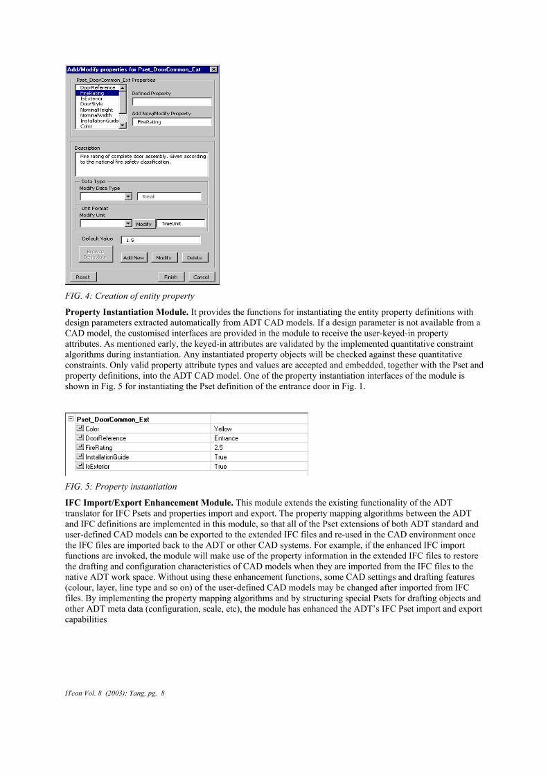
FIG. 4: Creation of entity property
Property Instantiation Module. It provides the functions for instantiating the entity property definitions with design parameters extracted automatically from ADT CAD models. If a design parameter is not available from a CAD model, the customised interfaces are provided in the module to receive the user-keyed-in property attributes. As mentioned early, the keyed-in attributes are validated by the implemented quantitative constraint algorithms during instantiation. Any instantiated property objects will be checked against these quantitative constraints. Only valid property attribute types and values are accepted and embedded, together with the Pset and property definitions, into the ADT CAD model. One of the property instantiation interfaces of the module is shown in Fig. 5 for instantiating the Pset definition of the entrance door in Fig. 1.
FIG. 5: Property instantiation
IFC Import/Export Enhancement Module. This module extends the existing functionality of the ADT translator for IFC Psets and properties import and export. The property mapping algorithms between the ADT and IFC definitions are implemented in this module, so that all of the Pset extensions of both ADT standard and user-defined CAD models can be exported to the extended IFC files and re-used in the CAD environment once the IFC files are imported back to the ADT or other CAD systems. For example, if the enhanced IFC import functions are invoked, the module will make use of the property information in the extended IFC files to restore the drafting and configuration characteristics of CAD models when they are imported from the IFC files to the native ADT work space. Without using these enhancement functions, some CAD settings and drafting features (colour, layer, line type and so on) of the user-defined CAD models may be changed after imported from IFC files. By implementing the property mapping algorithms and by structuring special Psets for drafting objects and other ADT meta data (configuration, scale, etc), the module has enhanced the ADT’s IFC Pset import and export capabilities
ITcon Vol. 8 (2003); Yang, pg. 8

3.3 Implementation of Server-Side Application The server-side application of the prototype is implemented in Java on Windows NT platform. The implementation makes use of WebSTEP (Eurostepsys, 2002b) as the IFC object repository. Java Servlets, JSPs and Java beans (Allamaraju et al, 2001) are developed to process the application logic and to provide the Web-based services to CAD clients and Web browser clients (see Fig 3).
Interfacing Module. Three interfacing components are developed in this module to support the data communication between the prototype server and its clients, which include CAD, quantity survey and structural engineering applications currently. Sharable interaction protocols in XML schema have been developed and implemented in these interfacing components. Fig 6 shows one of such protocols for sending and receiving the structural analysis model data in XML.
FIG. 6: XML schema for structural analysis model
Core Module. As described in Fig. 3, five components are implemented in this module. • The vocabulary facility provides GUIs for vocabulary database administrators to create, validate,
modify, delete and maintain the common vocabulary library, which defines the names and terms shared among project participants and applications. It also provides services to end-users for downloading and updating the client copy of the vocabulary database.
• The major role of the XML transformation component is to query and extract XML objects from a source XML file representing architectural design, and to populate the extractions to target XML files following the interaction protocols defined in the Interfacing Module. Transformation from big XML models to small ones facilitates effective exchange of application-specific XML data over the Internet. By invoking this service, the encapsulated design semantics in the extended architectural design XML files are transformed then exchanged with other AEC software applications. The current implementation supports the XML transformation from architectural design to quantity survey application, as well as the XML object query for quantity information.
• The geometric and topologic information processing component analyses the geometry of architectural design IFC files, identifies and idealises the load-bearing elements, and generates topologic relationships among the idealised structural elements to build structural analysis models. The resulting structural model data are then used to instantiate the XML schema in Fig. 6, from which XML files describing these structural analysis models are generated and communicated with the structural engineering applications.
• The information service component provides online information services to Web browser clients. Through HTML pages, users interact with the server for 3D architectural IFC models visualisation,
ITcon Vol. 8 (2003); Yang, pg. 9

3D structural model viewing and editing, BoQ (bill of quantity) query, property objects adding to models in XML format, IFC and XML objects query, and browsing of the model data structures.
• The server management component provides facilities for IFC and XML objects management and for system and user management. It maintains the model data integrity and consistency in the repository. For example, when additional Pset objects are inserted to or deleted from an IFC model stored in the repository, the linkage relations of these Pset objects with individual CAD objects in these models will be processed and checked by this component to ensure the information consistent. Transactional mechanisms are implemented for structural model data editing and Pset objects adding, so that the data integrity for these objects is maintained. It also provides methods for user profile and system log record management.
4. APPLICATION SCENARIOS In this section, the usage of the Web-based information service prototype is illustrated by a series of application scenarios, including IFC-compliant CAD information modelling, online services for IFC and XML object manipulations, and design information exchange and sharing across different AEC applications.
4.1 Design Information Modelling Scenario This scenario demonstrates the IFC-compliant design information modelling with Pset extensions by use of the client-side application of the prototype – the ADT add-on toolkit. The modelling of a non-standard ADT CAD object, such as a basin, is taken as an example in this scenario.
The 3D CAD geometry of the basin is modelled by the ADT system and packed with multi-view blocks to fully describe the graphical representations of the CAD object. By right-mouse click on the CAD model, the add-on tool is invoked from within the ADT environment to define the entity properties and Psets and to extract/define design characteristics for these property objects (shown in Fig. 7).
Properties are mapped & exported to IFC files
FIG. 7: Design information modelling with Pset extensions
ITcon Vol. 8 (2003); Yang, pg. 10

Once the property attribute instantiations are completed and the CAD file saved, a linkage between the CAD object and the Pset object is recorded and stored, with all defined properties, into the basin drawing database. The property attributes can be modified in the ADT environment and exported in IFC format. Any other building objects can be modelled similarly by the add-on toolkit for encapsulating Pset information into the design objects. The final architectural design is then exported into an IFC file with all Pset extensions, which will be uploaded to the server for sharing the design information with downstream quantity survey and structural analysis applications.
When the basin model in IFC is imported back to CAD, the embedded properties will be re-used to set the basin CAD model by clicking on the “Model Regenerate” button in Fig. 7. As some special Psets have been implemented in the add-on tool to retain the ADT drafting meta data in the basin’s IFC file, this non-standard basin CAD model can be fully restored from the imported IFC file without loss of any its original drafting features.
4.2 Online Services In this scenario, the server-side application of the prototype is used to provide online services for Web browsers. An extended IFC file for a sample CAD design is uploaded to the server’s repository and used as a shared information resource for description of the server’s functionality.
3D IFC model visualisation. An IFC to VRML conversion tool is wrapped in the server. Any IFC models in the server repository can be viewed from a Web browser. Allowed manipulations to the browsed model include zooming, translation, rotation, and selection. Fig. 8 shows the 3D structural elements in the sample design file.
FIG. 8: Visualisation of IFC model
3D structural model viewing and editing. With a Java3D enabled browser, any structural analysis models generated by the prototype from architectural IFC files can be displayed and edited. Fig. 9 shows a 3D structural analysis model and one of the editing interfaces for adding structural Psets and properties to the structural model through a browser.
FIG. 9: Viewing and editing of structural model
ITcon Vol. 8 (2003); Yang, pg. 11

IFC model structure browsing. Users can use an information structure browser to navigate through the extended IFC model structures. It is especially useful for users to allocate design objects when additional property objects are attached to or deleted from the design objects in an IFC model.
Property object manipulation and sharing. Users from different design disciplines need to share project data, such as architectural and structural design models and semantic properties. The server supports the manipulations to the property objects in the server’s repository through browsers. Additional properties can be added to the IFC model in the repository by supplying a property XML file from a client or by directly using the data entered from an interactive interface of the client browser. For example, a structural engineer may edit the structural model in Fig. 9 by adding a joint Pset and other needed properties to some structural element through the editing interface. By clicking on the “Save” button in Fig. 9, this modification is sent back to the server. Based on the information received, the server adds the joint Pset and all properties to the specified structural element in the IFC product model. As any additional Psets/properties added from an authorised client browser are incorporated into the common product model itself at the server’s repository, these Psets and properties are ready for sharing with any other computer applications. Besides adding operations, modification and deletion of the property objects are also allowed.
IFC/XML objects query. Users can invoke the online query services to retrieve the model data in IFC or XML format from the server’s repository. The object access granularity can be set at the object and sub-model levels. One of the XML quantity information queries at the object level is given in Fig. 10.
FIG. 10: XML object query for quantity information
4.3 XML Based Information Exchange This scenario describes the exchange of information between CAD and quantity take-off by use of a sample design file.
Using the server facility for IFC-XML conversion, an XML file sized 3.4 MB is generated from the sample IFC model. All the Pset extensions, schedule data sets, and quantity data sets are presented in this XML file. In general, the size of an XML file for a complete design is huge. It is not practical to transfer so big block of XML data over the Internet. To individual applications, only relevant data sets from the original model are needed. The server has developed XML transformation methods to extract and store the relevant information into different XML files for different applications. Through Web pages, the users specify the building objects to query quantity information of these objects. Based on the quantity survey requests, the server generates a small XML file containing only requested quantity information with a size of 47 KB. It also creates a BoQ report and places it on the client’s Web browser. Fig. 11 is an example of such a report. If detailed BoQ about one particular type of objects is required, the server will generate another report with the refined quantity information.
ITcon Vol. 8 (2003); Yang, pg. 12
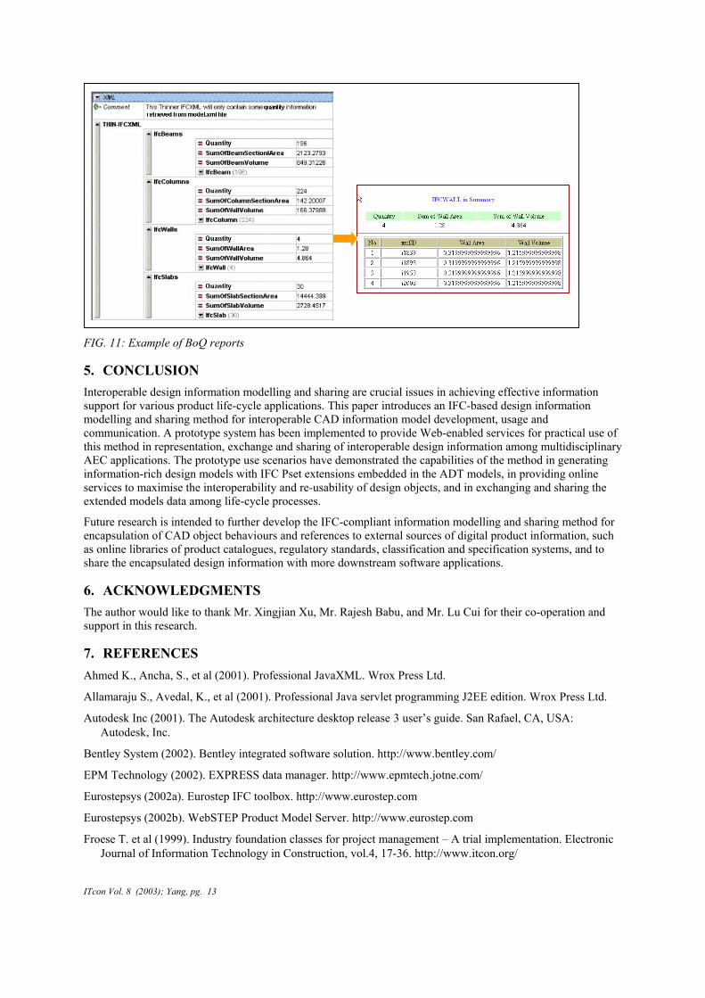
FIG. 11: Example of BoQ reports
5. CONCLUSION Interoperable design information modelling and sharing are crucial issues in achieving effective information support for various product life-cycle applications. This paper introduces an IFC-based design information modelling and sharing method for interoperable CAD information model development, usage and communication. A prototype system has been implemented to provide Web-enabled services for practical use of this method in representation, exchange and sharing of interoperable design information among multidisciplinary AEC applications. The prototype use scenarios have demonstrated the capabilities of the method in generating information-rich design models with IFC Pset extensions embedded in the ADT models, in providing online services to maximise the interoperability and re-usability of design objects, and in exchanging and sharing the extended models data among life-cycle processes.
Future research is intended to further develop the IFC-compliant information modelling and sharing method for encapsulation of CAD object behaviours and references to external sources of digital product information, such as online libraries of product catalogues, regulatory standards, classification and specification systems, and to share the encapsulated design information with more downstream software applications.
6. ACKNOWLEDGMENTS The author would like to thank Mr. Xingjian Xu, Mr. Rajesh Babu, and Mr. Lu Cui for their co-operation and support in this research.
7. REFERENCES Ahmed K., Ancha, S., et al (2001). Professional JavaXML. Wrox Press Ltd.
Allamaraju S., Avedal, K., et al (2001). Professional Java servlet programming J2EE edition. Wrox Press Ltd.
Autodesk Inc (2001). The Autodesk architecture desktop release 3 user’s guide. San Rafael, CA, USA: Autodesk, Inc.
Bentley System (2002). Bentley integrated software solution. http://www.bentley.com/
EPM Technology (2002). EXPRESS data manager. http://www.epmtech.jotne.com/
Eurostepsys (2002a). Eurostep IFC toolbox. http://www.eurostep.com
Eurostepsys (2002b). WebSTEP Product Model Server. http://www.eurostep.com
Froese T. et al (1999). Industry foundation classes for project management – A trial implementation. Electronic Journal of Information Technology in Construction, vol.4, 17-36. http://www.itcon.org/
ITcon Vol. 8 (2003); Yang, pg. 13
Graphisoft R&D (2002). IFC supports. http://www.graphisoft.com/products/ifc_supports/
Han C.S., Kunz J.C. and Law K.H. (1998). A client/server framework for on-line building code checking. Journal of Computing in Civil Engineering, vol.12, no.4, 181-194. New York: American Society of Civil Engineers.
Hitchcock R. (2000). Acquiring geometry from CAD for EnergyPlus through the use of Industry Foundation Classes. Building Energy Simulation User News. Vol. 21, no. 5, 2-5.
International Alliance for Interoperability (IAI) (2000, 1999, 1998). Industry Foundation Classes - Release 2x, Release 2.0 and Release 1.5.1. IAI.
International Alliance for Interoperability (IAI) (2001). IFC2x property set development guide. IAI.
Nemetschek AG (2002). http://www2.nemetschek.com/
PDTec GmbH (2002). ECCO toolkit. http://www.pdtec.de/
Productivity and Standards Board (PSB) of Singapore (2001). CP83: Code of Practice for Construction Computer-Aided Design. PSB.
Stouffs R. and Krishnamurti R. (2001). On the road to standardisation. Proceedings of CAAD Futures 2001. 75-88.
YIT Corporation (2002). A product model boosts the efficiency of the construction process. http://www.yit.fi/
Yang Q and Li X. (2001). Representation and execution of building codes for automated code checking. Proceedings of CAAD Futures 2001. 315-329.
ITcon Vol. 8 (2003); Yang, pg. 14