Embed Size (px)
Citation preview
8 Edition 02.11Technical Information · GB
• Electrical ignition of gas burners• Ignition and burner control with a single electrode possible• For installation in a control cabinet or wall mounting• Complying with EN 61558-2-3• TZI 7,5-20/33R complies with CSA
Ignition transformers TZI, TGI
TZI, TGI · Edition 02.11 2▼ = To be continued
ContentsIgnition transformers TZI, TGI . . . . . . . . . . . . . . . . . . . . . . . 1Contents . . . . . . . . . . . . . . . . . . . . . . . . . . . . . . . . . . . . . . . . 21 Application . . . . . . . . . . . . . . . . . . . . . . . . . . . . . . . . . . . . . 31.1 Examples of application. . . . . . . . . . . . . . . . . . . . . . . . . . 5
1.1.1 Double-electrode operation . . . . . . . . . . . . . . . . . . . . . . . . . .51.1.2 Single-electrode operation . . . . . . . . . . . . . . . . . . . . . . . . . . .5
2 Certification . . . . . . . . . . . . . . . . . . . . . . . . . . . . . . . . . . . . 63 Function . . . . . . . . . . . . . . . . . . . . . . . . . . . . . . . . . . . . . . . 73.1 Connection diagrams . . . . . . . . . . . . . . . . . . . . . . . . . . . 7
4 Selection . . . . . . . . . . . . . . . . . . . . . . . . . . . . . . . . . . . . . . 84.1 Selection table . . . . . . . . . . . . . . . . . . . . . . . . . . . . . . . . . 84.1.1 Type code. . . . . . . . . . . . . . . . . . . . . . . . . . . . . . . . . . . . . . . . 8
5 Project planning information . . . . . . . . . . . . . . . . . . . . . . 95.1 Operation . . . . . . . . . . . . . . . . . . . . . . . . . . . . . . . . . . . . . 95.2 Installation . . . . . . . . . . . . . . . . . . . . . . . . . . . . . . . . . . . . 95.3 Cable selection . . . . . . . . . . . . . . . . . . . . . . . . . . . . . . . . 95.4 Ignition electrode . . . . . . . . . . . . . . . . . . . . . . . . . . . . . . 95.5 Reduction of EMC, wiring . . . . . . . . . . . . . . . . . . . . . . . . 95.6 Single-electrode operation. . . . . . . . . . . . . . . . . . . . . . 105.7 Intermittent operation/Star electrodes. . . . . . . . . . . . . 105.8 Duty cycle. . . . . . . . . . . . . . . . . . . . . . . . . . . . . . . . . . . . 10
6 Accessories . . . . . . . . . . . . . . . . . . . . . . . . . . . . . . . . . . . .116.1 High-voltage cable . . . . . . . . . . . . . . . . . . . . . . . . . . . . .116.2 Radio interference suppressed electrode adapters . .11
7 Technical data . . . . . . . . . . . . . . . . . . . . . . . . . . . . . . . . . 127.1 Dimensions. . . . . . . . . . . . . . . . . . . . . . . . . . . . . . . . . . . 13
Feedback . . . . . . . . . . . . . . . . . . . . . . . . . . . . . . . . . . . . . . 14Contact . . . . . . . . . . . . . . . . . . . . . . . . . . . . . . . . . . . . . . . . 14
TZI, TGI · Edition 02.11 3
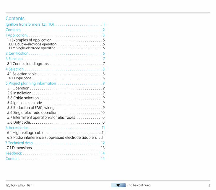
TZI 5-15/20TZI 5-15/100, TZI 7-25/20, TZI 7,5-12/100, TZI 7,5-20/33 TGI
1 ApplicationIgnition transformers TZI and TGI are designed for high-voltage spark ignition of gas burners and gas-ignited or directly ig-nited oil burners. The ignition transformers can also be used on burners with single-electrode operation; the ignition cur-rent and ionization current flow over a common electrode. Ignition transformer TZI fulfils the requirements for enclosure IP 20. It is suitable for installation in a control cabinet. Igni-tion transformer TGI in its die-cast aluminium housing meets the requirements for enclosure IP 65. It is suitable for on-site mounting near to the burner.
TZI, TGI · Edition 02.11 4
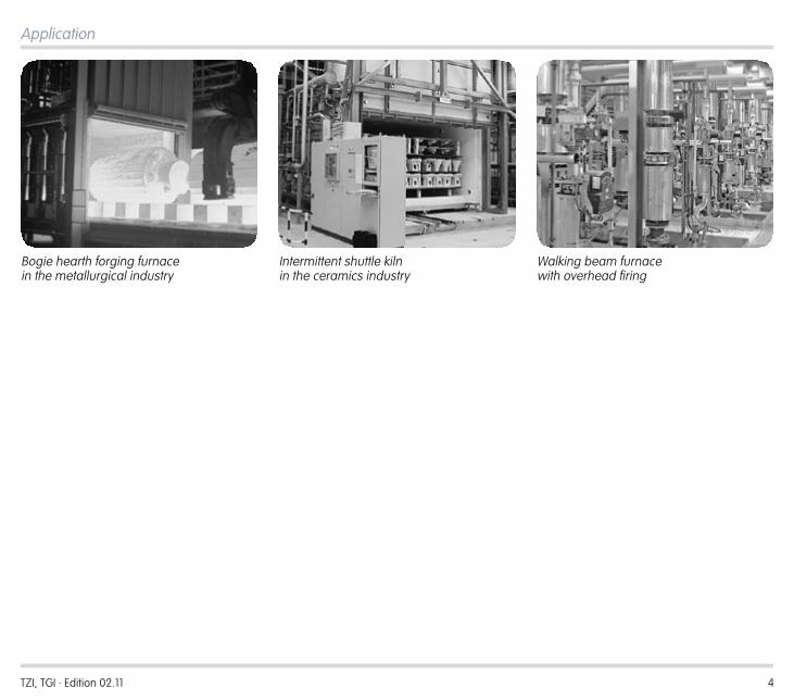
Bogie hearth forging furnace in the metallurgical industry
Intermittent shuttle kiln in the ceramics industry
Walking beam furnace with overhead firing
Application
TZI, TGI · Edition 02.11 5
IFD 258
BIO/BIC
VAS
VR..R
GIK
NL1
TGI
IFD 258
BIO/BIC
VAS
GIK
NL1
TGI
VR..R
Application
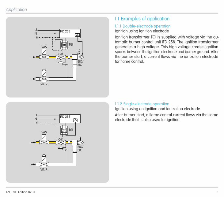
1 .1 Examples of application1 .1 .1 Double-electrode operationIgnition using ignition electrodeIgnition transformer TGI is supplied with voltage via the au-tomatic burner control unit IFD 258. The ignition transformer generates a high voltage. This high voltage creates ignition sparks between the ignition electrode and burner ground. After the burner start, a current flows via the ionization electrode for flame control.
1 .1 .2 Single-electrode operationIgnition using an ignition and ionization electrode.After burner start, a flame control current flows via the same electrode that is also used for ignition.
TZI, TGI · Edition 02.11 6
2 CertificationIgnition transformers TZI and TGI are built for applications pursuant to the Machinery Directive 2006/42/EC.
TZI 7,5-20/33RComplies with Canadian Standards Association CSA C22.2 No. 13-1962.
TZI, TGI · Edition 02.11 7
H
∅ 7 mm (0.275")
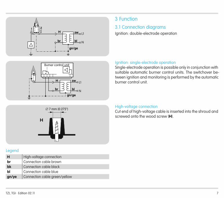
3 Function3 .1 Connection diagramsIgnition: double-electrode operation
Ignition: single-electrode operationSingle-electrode operation is possible only in conjunction with suitable automatic burner control units. The switchover be-tween ignition and monitoring is performed by the automatic burner control unit.
High-voltage connectionCut end of high-voltage cable is inserted into the shroud and screwed onto the wood screw (H).
LegendH High-voltage connectionbr Connection cable brownbk Connection cable blackbl Connection cable bluegn/ye Connection cable green/yellow
sw
bl
gn/ge
H
br
L1
N
Burner control unit
sw
bl
gn/ge
H
br
I Z
L1
N
TZI, TGI · Edition 02.11 8
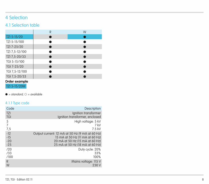
4 Selection4 .1 Selection table
R WTZI 5-15/20 ● ●
TZI 5-15/100 ● ●
TZI 7-25/20 ● ●
TZI 7,5-12/100 ● ●
TZI 7,5-20/33 ● ●
TGI 5-15/100 ● ●
TGI 7-25/20 ● ●
TGI 7,5-12/100 ● ●
TGI 7,5-20/33 ● ●
Order exampleTZI 5-15/20W
� = standard, � = available
4 .1 .1 Type codeCode DescriptionTZITGI
Ignition transformerIgnition transformer, enclosed
577,5
High voltage: 5 kV7 kV
7.5 kV-12-15-20-25
Output current: 12 mA at 50 Hz (9 mA at 60 Hz)15 mA at 50 Hz (11 mA at 60 Hz)
20 mA at 50 Hz (15 mA at 60 Hz)25 mA at 50 Hz (18 mA at 60 Hz)
/20/33/100
Duty cycle: 20%33%
100%RW
Mains voltage: 115 V230 V
TZI, TGI · Edition 02.11 9
5 Project planning information5 .1 OperationThe ignition transformers are suitable only for applications for igniting gas burners and gas-ignited or directly ignited oil burners. Do not operate the transformers when no ignition sparks are created.
5 .2 InstallationInstallation position for TZI and TGI: install in a horizontal posi-tion, or with the connections facing down.Install the ignition transformer directly on the burner (recom-mended ignition cable length: max. 5 m, recommended < 1 m).
TZILength of the mains cable is 410 mm.The ignition transformer has enclosure IP 20. In the event that a different enclosure is needed, install the ignition transformer in a corresponding housing or in a control cabinet as necessary.
5 .3 Cable selectionUse mains cable suitable for the type of operation and com-plying with local regulations.Install an equipotential bond (4 mm2, compliant with local regulations) between burner and ignition transformer.Use unscreened high-voltage cable for the ignition cable, see page 11 (Accessories).Recommended ignition cable length: max. 5 m, recommended < 1 m. The longer the ignition ca-ble, the lower the ignition capacity.
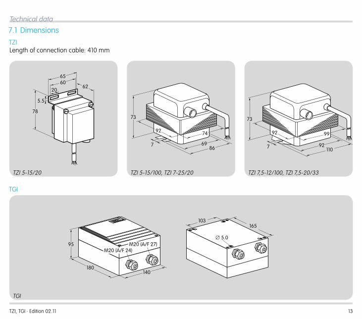
TGIThe TGI housing has two A/F 27 cable glands with double seal inserts for two cables up to 7 mm in diameter. A seal insert for 10 to 14 mm is enclosed and can be used in the A/F 27 cable gland, see page 13 (Dimensions).
5 .4 Ignition electrodeThe distance between ignition electrode and burner ground should be 2 ± 0.5 mm.
5 .5 Reduction of EMC, wiringAvoid external electrical interference.Lay cables individually and, if possible, not in a metal conduit.Do not lay UV/ionization cable and ignition cables together and lay them as far apart as possible.Screw the ignition cable securely into the high-voltage con-nection on the ignition transformer and run to the burner by the shortest possible route, see page 7 (High-voltage connection).Use an interference suppressed electrode adapter on the burner (with 1 k Ω resistor), see page 11 (Accessories).
TZI, TGI · Edition 02.11 10
5 .6 Single-electrode operationSingle-electrode operation is possible only in conjunction with suitable automatic burner control units.For single-electrode operation, wire an equipotential bond between the burner and the automatic burner control unit, see page 7 (Ignition: single-electrode operation). Ensure that the wiring has been done correctly, otherwise the connected units will be damaged.
5 .7 Intermittent operation/Star electrodesWe recommend using 7.5 kV ignition transformers for On/Off intermittent operation or when using burners with star electrodes.
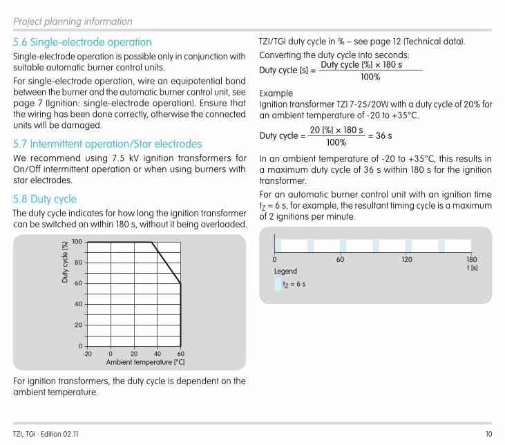
5 .8 Duty cycleThe duty cycle indicates for how long the ignition transformer can be switched on within 180 s, without it being overloaded.
-20 0 20 40 600
20
40
60
80
100
Dut
y cy
cle
[%]
Ambient temperature [°C]
For ignition transformers, the duty cycle is dependent on the ambient temperature.
TZI/TGI duty cycle in % – see page 12 (Technical data).Converting the duty cycle into seconds:
Duty cycle [s] =Duty cycle [%] × 180 s
100%
Example Ignition transformer TZI 7-25/20W with a duty cycle of 20% for an ambient temperature of -20 to +35°C.
Duty cycle =20 [%] × 180 s
100%= 36 s
In an ambient temperature of -20 to +35°C, this results in a maximum duty cycle of 36 s within 180 s for the ignition transformer.For an automatic burner control unit with an ignition time tZ = 6 s, for example, the resultant timing cycle is a maximum of 2 ignitions per minute.
0 60 120 180
tZ = 6 s
t [s]Legend
Project planning information
TZI, TGI · Edition 02.11 11
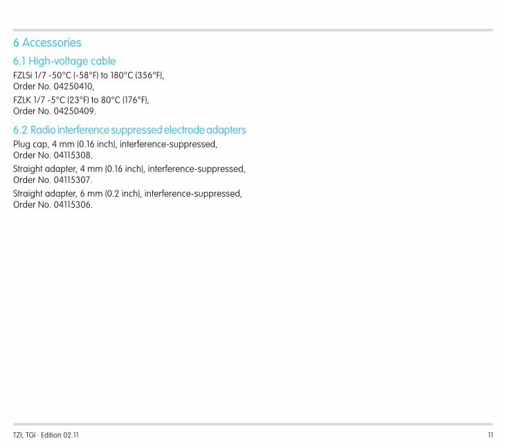
6 Accessories6 .1 High-voltage cableFZLSi 1/7 -50°C (-58°F) to 180°C (356°F), Order No. 04250410,FZLK 1/7 -5°C (23°F) to 80°C (176°F), Order No. 04250409.
6 .2 Radio interference suppressed electrode adapters Plug cap, 4 mm (0.16 inch), interference-suppressed, Order No. 04115308.Straight adapter, 4 mm (0.16 inch), interference-suppressed, Order No. 04115307.Straight adapter, 6 mm (0.2 inch), interference-suppressed, Order No. 04115306.
TZI, TGI · Edition 02.11 12
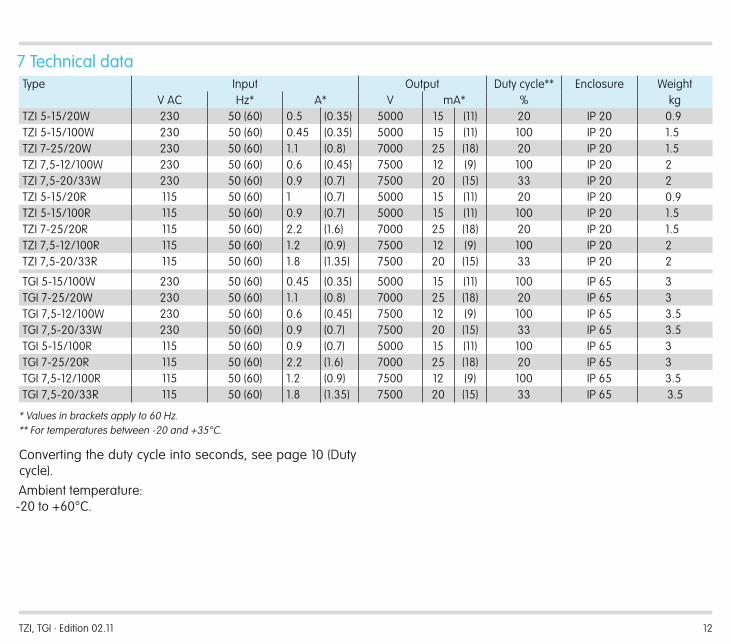
7 Technical dataType Input Output Duty cycle** Enclosure Weight
V AC Hz* A* V mA* % kgTZI 5-15/20W 230 50 (60) 0.5 (0.35) 5000 15 (11) 20 IP 20 0.9TZI 5-15/100W 230 50 (60) 0.45 (0.35) 5000 15 (11) 100 IP 20 1.5TZI 7-25/20W 230 50 (60) 1.1 (0.8) 7000 25 (18) 20 IP 20 1.5TZI 7,5-12/100W 230 50 (60) 0.6 (0.45) 7500 12 (9) 100 IP 20 2TZI 7,5-20/33W 230 50 (60) 0.9 (0.7) 7500 20 (15) 33 IP 20 2TZI 5-15/20R 115 50 (60) 1 (0.7) 5000 15 (11) 20 IP 20 0.9TZI 5-15/100R 115 50 (60) 0.9 (0.7) 5000 15 (11) 100 IP 20 1.5TZI 7-25/20R 115 50 (60) 2.2 (1.6) 7000 25 (18) 20 IP 20 1.5TZI 7,5-12/100R 115 50 (60) 1.2 (0.9) 7500 12 (9) 100 IP 20 2TZI 7,5-20/33R 115 50 (60) 1.8 (1.35) 7500 20 (15) 33 IP 20 2
TGI 5-15/100W 230 50 (60) 0.45 (0.35) 5000 15 (11) 100 IP 65 3TGI 7-25/20W 230 50 (60) 1.1 (0.8) 7000 25 (18) 20 IP 65 3TGI 7,5-12/100W 230 50 (60) 0.6 (0.45) 7500 12 (9) 100 IP 65 3.5TGI 7,5-20/33W 230 50 (60) 0.9 (0.7) 7500 20 (15) 33 IP 65 3.5TGI 5-15/100R 115 50 (60) 0.9 (0.7) 5000 15 (11) 100 IP 65 3TGI 7-25/20R 115 50 (60) 2.2 (1.6) 7000 25 (18) 20 IP 65 3TGI 7,5-12/100R 115 50 (60) 1.2 (0.9) 7500 12 (9) 100 IP 65 3.5TGI 7,5-20/33R 115 50 (60) 1.8 (1.35) 7500 20 (15) 33 IP 65 3.5
* Values in brackets apply to 60 Hz.** For temperatures between -20 and +35°C.
Converting the duty cycle into seconds, see page 10 (Duty cycle).Ambient temperature: -20 to +60°C.
TZI, TGI · Edition 02.11 13
78
6220
6065
5.5
7492
73
7 6986
73
7 92110
9992
TZI 5-15/20 TZI 5-15/100, TZI 7-25/20 TZI 7,5-12/100, TZI 7,5-20/33
TGI
Technical data
7 .1 DimensionsTZILength of connection cable: 410 mm
TGI
140180
95 M20 (A/F 27)M20 (A/F 24)
103165
∅ 5.0
TZI, TGI · Edition 02.11
ClarityFound information quicklySearched for a long timeDidn’t find informationWhat is missing?
ComprehensionCoherentToo complicatedNo answer
ScopeToo littleSufficientToo wideNo answer
No answer
NavigationI can find my way aroundI got “lost”No answer
UseTo get to know the productTo choose a productPlanningTo look for information
My scope of functionsTechnical departmentSalesNo answer
Remarks
(Adobe Reader 7 or higher required) www.adobe.com
Elster GmbH Postfach 2809 · 49018 Osnabrück Strotheweg 1 · 49504 Lotte (Büren) GermanyT +49 541 1214-0 F +49 541 1214-370 [email protected]
The current addresses of our international agents are available on the Internet:www.kromschroeder.de/index.php?id=718&L=1
We reserve the right to make technical modifications in the interests of progress.Copyright © 2013 Elster GmbH All rights reserved.
Feedback
Contact
Finally, we are offering you the opportunity to assess this “Technical Information (TI)” and to give us your opinion, so that we can improve our documents further and suit them to your needs.
0325
0846

![Studie „Technologische und anwendungsorientierte Potenziale …rue/PDF-Dateien/TZI-Bericht... · 2003. 6. 6. · [wearLab]@tzi TZI-Bericht Nr. 24 Studie „Technologische und anwendungsorientierte](https://img.pdfslide.net/doc/110x75/5fef5bc275df9b71697aa358/studie-atechnologische-und-anwendungsorientierte-potenziale-ruepdf-dateientzi-bericht.jpg)