Embed Size (px)
Citation preview

~-rz,- i-
~ ~7T'ROYAL AI-RC.RAFTl ETA4LISIrMEN1
TECHNIfCAL 49P-ORT No.` 66034,
cW N. 4.vi"
CL4 MA L Cs'w N O ut U"~ C"1 i Z
^F IiPJONS NVAC

U.D.C. No. 536.212.2 : 621.884.052.2 : 533.5 : 669.715
ROYAL AIRCRAFT ES.T'AB LI SHM ENT
Technical Report No. 66034,
February 1966
T1!MMAL C0NDUCTANCE OF LAP-JOINTS IN VACUUM
by
A. B. Osborn
W. N. Mair
SUMARY
Experiments on the thermal conductance, in vacuum, of lap-jointed
specimens of aluminium-clad L72, and unclad L70, aluminium alloys (4% Cu;
O.7. Si; 0.71 Mn) P.re described. The specimens were strips of thin sheet
fastened with rivets, or nuts and bolts. The effects of variability of
riveting technique, temperature, thermal cycling, overlap area, bolting-
torque, burrs, and interlayers of paint, anti-corrosive jointing compound,
indium and electrical insulators were studied. In general, the results
szutport a mechanism of high heat transfer, by metallic conduction, near the
rivets or bolts only. This hypothesis is discussed, and it is suggested
that the thermal behaviour of the specimens is described better in terms of
an additional length of heat-conduction path than by a conventional heat
transfer coefficient.
It was found, if burrs are removed, that both careful bolt-tightening
and standard, aircraft-construction, riveting techniques produce thermally
good lap-joints for which the effect of the doubled thickness is equal to,
or greatcr than, the opposing effect of the interfacial thermal resistance.
Best Available Copy
Dep artmental Reference: CPM. 60 p

T2
CONTENS Page
I INTRODUCTION 32 EEPM•MNTAL METHOD 1.
2.1 Specimens 4
2,2 Test apparatus 5
2.j Experimental procedure 6
3 TnEoRY OF THE METHOD 6
4 RESULTS 8
4.1 Riveted L72 lap-joints 8
4.1.1 Preliminary results fcr machine-set rivets 8
4.1.2 Hand-riveting 10
4.1.3 Final results fo- standard riveting patterns 11
4.1.4 Effects 2 temperature and temperature cycling 11
4.2 Bolted L72 lap-joints 12
4.2.1 Bolted L7C lap-joints with 4 lb in fastening torque 12
4.2.2 The eff,'ot of fastening torque 13
4.3 Effect of surface hardness and roughness 14
4..3.1 Bolted L70 lap-joints 14
4.3.2 Irdium interlayers 16
4.3.3 The effect of burrs 17
4.4 Miscellaneous factors: electrically insulating joints 18
4,.4.1 Insulated screws 18
4.4.2 Electrically insulated lap-joints 19
4.4..3 Anti-corrosive jointing compound 19
4.4.4 The effects of paint layers 20
5 DISCUSSION 21
6 CONCLUSIONS 24
ACKNOWLDEGMEET 25
Appendix A Riveting - standard aircraft practice 2
Appendix B Thermocouples 27
Appendix C Theory of the lap-jointed strip in the steady state, 28excluding radiation and gas-conduction
Appe-ndix D The effects of radiation and gaseous conduction 32
References 36
Illustratibns Figures 1-8
Detachable abstract cardz

3
1 IMTRODUCTION
This paper describes experiments made to obtain data, on the thermal
conductanoe of riveted and bolted joints between metals, that would be relevant
to the engineering design of space-vehicles. The problems of the thermal
balance of a space-vehicle are those of spreading, and finally radiating tO
space, the heat, received from the sun and dissipated by electronic packages,
in such a way that no part of the vehicle exceeds, at any time; its maximum
operating temperature. Radiation is the brst way of transferring heat over
large distances; however for small distances conduction can give a useful
contribution. A joint in a metallic conduction path introduces a thermal
resistance at the interface. At atmospheric pressure, gaseous conduction
as:ssts in the ransfer of heat between two metals pressed together; in the
vwcuum of space (see Appendix D), this contribution is absent.
The interfacial resistance of a joint occurs because only the peaks of
microscopic surface irregularities make actual contact. If the contact
* pressure is applied uniformly over the joint area, there is, for most flat
engineering surfaces, a fairly uniform distribution of contact points; the
number increases with surface smoothness. An increase in the pressure causes
deformation and flow of the contacting asperities, which increase both in
size and number until the area of real contact is silfficient to jupport the
lead. The area of real contact is usually only a small fraction of the
total area of the interface (see Section 5). Since the thermal conductance
of the metals is usually greater than that of any fluid filling the gap, the
lines of heat flow converge towards the contact points where they are restricted
to narrow channels thus causing 2a "constriction resistance". Several analyses
of the idealiz,-d situation have been published3 's45 and experimental results
show6'7'8,9,i0 that the thermal conductmce of an interface varies as
Drudicted with thermal conductivity, mechanical pressure, surface hardness
and surface finish. Guarded hot plate thermal conductivity apparatus, in which
the pressure is applied uniformly over the area of the interface, was used
and the results given in terms of the coefficient of heat transfer h, i.e.,
the heat flux per unit temperatire difference across the interface.
However, such ressults are not directly applicable to the types of
,joints aoually made by engineers. In normal aircraft practice, joints are
fastened by ritrets or bolts, and the contact pressure is no longer uniform
over tho interface. The pressure is •igh under the head of the fastener 12,
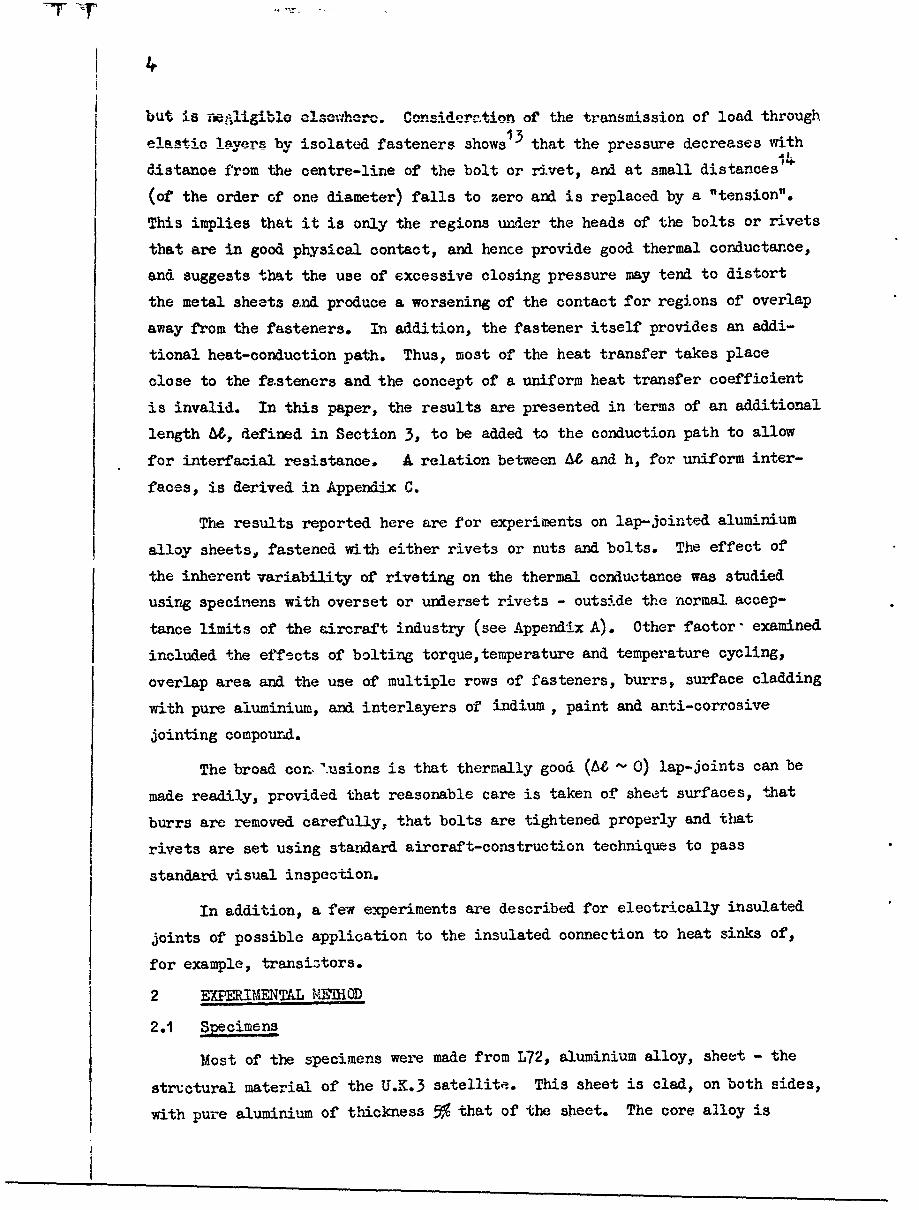
but iS _e_.ligible clsc r••erc.. Considertionn of the transmission of load through
ela-stic !ayvers by isolated fasteners shows13 that the pressure decreases withIi.
distance from the centre-line of the bolt or rivet, and at small distances""
(of the order of one diameter) falls to zero and is replaced by a "tension".
This implies that it is only the regions under the heads of the bolts or rivets
that are in good physical contact, and hence provide good thermal conductance,
and suggests that the use of excessive closing pressure may tend to distort
the metal sheets and produce a worsening of the contact for regions of overlap
away from the fasteners. In addition, the fastener itself provides an addi-
tional heat-conduction path. Thus, most of the heat transfer takes place
close to the fasteners and the concept of a uniform heat transfer coefficient
is invalid. In this paper, the results are presented in terms of an additional
length U, defined in Section 3, to be added to the conduction path to allow
for interfacial resistance. A relation between At and h, for uniform inter-
faces, is derived in Appendix C.
The results reported here are for experiments on lap-jointed aluminium
alloy sheets, fastened with either rivets or nuts and bolts. The effect of
the inherent variability of riveting on the thermal conductance was studied
using specinens with overset or underset rivets - outside the normal accep-
tance limits of the aircraft industry (see Appendix A). Other factor- examined
included the effects of bolting torque, temperature and temperature cycling,
overlap area and the use of multiple rows of fasteners, burrs, surface cladding
with pure aluminium, and interlayers of indium, paint and anti-corrosive
jointing compound.
The broad con, usions is that thermally good (AZ - 0) lap-joints can be
made readily, provided that reasonable care is taken of sheet surfaces, that
burrs are removed carefully, that bolts are tightened properly and that
rivets are set using standard aircraft-construction techniques to pass
standard visual inspection.
In addition, a few experiments are described for electrically insulated
joints of possible application to the insulated connection to heat sinks of,
for example, transistors.
2 E• RIMENT• L ME'IHOD
2.1 Specimens
Most of the specimens were made from L72, aluminium alloy, sheet - the
structural material of the U.K.3 satellite. This sheet is clad, on both sides,
with pure aluminium of tlhickness 5% that of the sheet. The core alloy is

5
aluminium containing 4• copper, 0.7% silicon and 0.75 manganese. L72 material
is heat-treated in its final form, and aged at room temperature. This leaves
the surface layer of pure aluminium in an annealed condition, which should
be ideal for :-aking good thermal cozitact; to check this, a few specimens
were made from L70 sheet, which -s the same core alloy in unclad form.
Each specimen was made by lap-jointing two rectangular strips of sheet
material: the joints were fastened either by •" diameter SP80 rivets*
(size 404) or by 6BA stainless steel nuts and balts (or screws); burrs,
raised in drilling clearance holes for the fasteners, were carefully
removed before the strips were assembled. The rivets were closed by
machine, at various settings, or by hand using a pneumatic gun (see Appendix A).
Nuts and bolts were tightened using torque spanners.
The various types of specimen and the patterns of fasteners used are
illustrated in Fig.1. The overall length of each specimen was about 25 cm.
For the earlier experiments, most of the specimens were made to a pattern A,
3 cm wide, thickness of order i mm (20 swg for L72, 0.002" Al cladding;
18 swg for L70) and with an overlap of 2.5 cm: pattern B was used to obtain
an increased heat flux. In later experiments, the standard riveting patterns
C, D and E were used.
Thermocouples were used to measure the distribution of temperature
along each specimen. Short lengths of chromel and alumel wVires were spot-
welded to the specimens (see Appendix B); thermocouple location was accurate
to about ±11 mm. Throughout the experiments there was a gradual improvement
in thermocouple technique; this is discussed in Appendices B and D.
2.2 Test apparatus
In essence, the appar-atus consisted of two copper blocks against which
the ends of a specimen were clamped (see Fig.2). The clamping plates were
of copper, 5/16" thick, backed by 1" plates of mild steel. The upper block,
containing a nichrome heater, was supported by stainless steel brackets from
the lower, water-cooled block. (The lower block also contained a heating
clemeot; its use is described in Appendix D). Boron nitride washers were
used to reduce heat losses to these brackets. Thermally insulating supports
were used between the lower block and the brass base-plate of the vacuum
apparatus.
• Al, 2% Cu alloy (L86), which does not age-harden appreoiably.
S° . ... i'•"• • BIS • .. •, _ •.,..,t r..,.-.,.e

A large glass bell-jar covered the apparatus and was evacuated through
a hole in the base-plate, by a 4" oil-diffusion pump. Two vacuum-tight sockets
carried the thermocouple leads through the base-plate to a selector s;itch
outside the vacuum system. These sockets were 24 way Plesse"' Mark IV sockets,
specially sealed with "Glyptal" cement and 0-ring gaskets.
2.3 Experimental procedure
Six lap-jointcd specimens, with short thermocouple wires already attached
were clamped in position between the two copper blocks. The thermocouple wires
were then electrically welded to similar wires from the base-plate sockets.
The apparatus was covered by the bell-jar and evAcuated to a final pressure
of about 5 x 10⁻⁵ torr.
Water-cooling was then applied to the lower block, and the upper block
was heated rapidly to the desired temperature. The heater current was then
reduced to a predetermined value, allowing the specimens to reach a steady
state teiupcrature distribution in About 1½ hours. Temperature observations
were observed repeatedly, at about hourly intervals, to check that the steady
state had been reached.
The normal conditions of test were a hot block temperatue of about
I0ooC and a water-cooled cold block temperatue of about 20O. Occasionally
a hot block temperature of about 200o. was used; attention is drawn to these
"hot" experiments in the resvlts of Section 4.
The thermocouple emf's, between the hot junctions on the specimens and
a reference junction held at 00 C in melting ice, were measured by a digital
voltmeter to an accuracy of t10 gV, i.e. a temperature accuracy of about _•°C .
The ¼ mm uncertainty in hot-junction location is equivalent to an additional
temperature uncertainty of about 1/100C.
The magnitude of the heat losses from the sides of a specimen, due to
conduotion in the residual gas in the apparatus and to radiation, is discussed
in Appendix D. It is shown to be negligible in a vacuum of 5 x 10 - torr for
a surface emissivity of 105 of a "black-body" or less.
3 THEORY OF TBE METHOD
In the experiments described in Section 2, specimens of lap-jointed
strips conduct heat from a hot black to a cold sink. For thin strips of high
thermal conductivity k, the flow of heat, in the absence of radiation and

7
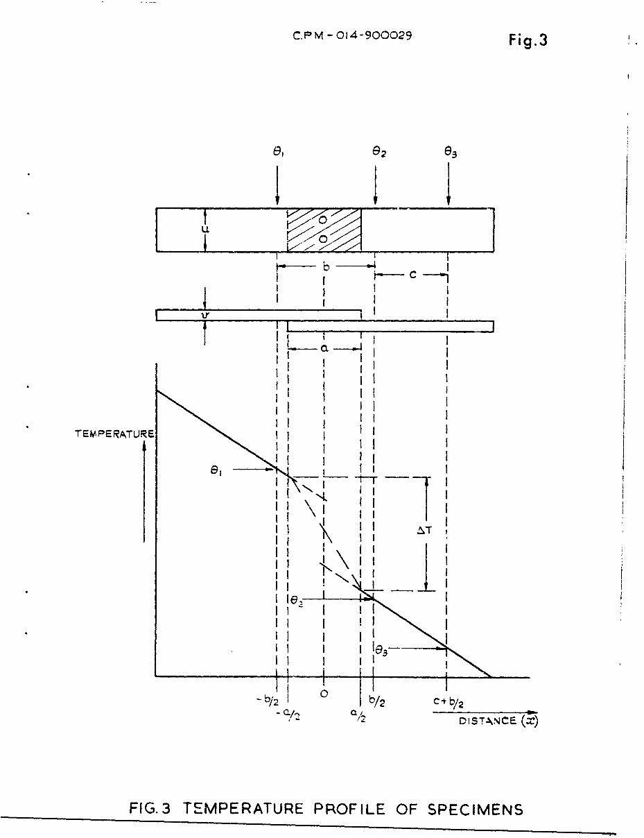
gas-conduction losses, is essentially one-dimensional. In the steady state,
the temperature gradient 6T/ax along thc strip n• + theht Plow Q are
constant everywhcre ap..art fom the overlap region -a/2 < x <, a/2 - Fig.3);
and
Q = -kuv 8-T
where u is the width and v the thickness of the strips.
The specimen temperature is normally observed at three positions; two
thermocouples are attached symmetrically with respect to the lap-joint
(x = Tib) and r third to the colder strip at x = c + -b. if the observed
temperatures, in the steady state, are e1, 62 and e3 respectively,
8 - E),5T_3 (2)axc
is the te-mpcrature gradient away from the joint itself, and the temperature
drop AT across the lap-joint - i.e., the difference in temperature of the
hotter strip at x = -Aa and the colder strip at x - la - is given by
AT = (6 -2) + (b - a) (3)
Division by -aT/ix gives the length &0 of a simple strip, of the same section
uv, of the same material having the same AT for the same heat flow Q. There-
fore, as regards its thermal resistance, a lap-joint, with an actual length a
of overlap, can be described as having an "effective length" 4, of continuous,
unjointed, strip. Hence,
= c (e: - (b - a) . (4.)\e2 - (33) ,
Thus a strip of total length 4, with an overlap length a, behaves
thermally as a continuous strip of length Z + (zo - a). The additional
length AU, due to the thermal resistance of ",e joint, is given by
M -a- a . (5)(= 2 -3

S~8
A high value of At indicates a poor thermal contact; for a joint in which the
effect of the doubled th-ickness of the overlap outweighs the interfacial
reesi-stance 66 is nP~ative.
4RESULTS
In this section, the results are given in terms of the additional length
i6, defined in Section 3; the lower the value of At , the better is the thermal
contact.
4.i Riveted L72 lap- joints
4.1.1 Preliminar results for machine-set rivets
In the fi,'st experiments, the effects of variability of riveting technique
on the thermal conductance of lap-joints was studied. Tae methods of machine-
and hand-riveting used, and the variability produced, are described in Appendix A.
The spec1iiens were 3 cm wide strips of 20 swg L72, joined with two rivets
(pattern A of Fig.1); the length of overlap was 1". Before riveting, the
drilling burrs were carefully removed.
It was noticed that the surface of the strips around the rivets were
deformed to produce a saucer-shaped depression; the effect was slight with
underset rivets, and greater with overset rivets.
The results obtained with overset and underset machine-riveting are given
in Table 1: the first column gives the specimen number - the middle digit
indicating the machine setting, 3 for underset and 4 for overset rivets. Sub-
sequent columns give the values of L& in millimetres obtained in successive
experiments. Between experiments the apparatus was cooled to room temperature
ard, in some cases, air was let in and pumped out again. In all experiments
the cold block was water-cooled at about 200C: in- most experiments the tempera-
ture of the hot block was about 1000 C; the restlts, for the three experiments
in which it was 200 C, ar- marked by * and /. In the third "hot" experiment
() the specimen was kept at temperatare for the relatively long duration of
6 hours.

Table I
Admm) for mderset. and overset m .chine-riveting
Specimen , ,number
131 1a9 0.5 0.6 1.0 1.3 0.4 0.9132 -0.9 --0.9 -1-4 -1.7 -0.4 0.0 0.9133 -1.8 -1.8 -2.4. -2.4 -1.3 -1.8 -1.4.134. -1.3 -0.9 -2.2 -1.3135 -1.7 -2.2 -3.4 -1.8136 0.0 0.0 -0.8 -1.8
14.1 1.9 0.2 0.2 2.2 1.8 1.4 1.3 2.2 0.6 2.2142 2.4 1.4 0.4 0.2 1.8 1.4 0.9143 2.9 1.9 1.9 1.)4 2.7 2.8 2.3144 2.2 2.8 1.7 2.314.5 0.4. 0.4 -1.2 -0.9
The most striking result is that JAZI for all specimens is less than
3 mm. The thermal contact of the lap-joints is therefore good, even though
the setting of the rivets is outside the limits that would be passed, by
visual inspection, for mechanical soundness.
Not all the scatter of these results is attributable to the a lbility
of riveting: in these experiments, small pieces of adhesive glass-. \ tape
were used to improve the mechanical strength of the thermocouple wse-s; radia-
tion losses from the thermally "black" tape may have introduced additional
variability.
In spite of the scatter, certain interesting deductions can be made
from these results, The average values of -M are shown in Table 2; the"normal" experiments are those for which the hot block temperature was abo,2t
1000C, compared with 2000C for the "hot" experiments.
Table 2
Average values of AZ (mm)
Underset Oversetrivets rivets
normal experiments -0.64 1.77hot experiments -1.17 0.60

10
vi car .e Pee f^r mah,-b 2 +2ha+ the ioint conductance is better in the
r hot experiments and is better for underset rivets. The latter is perhaps
t surprising; at first glance, it might be expected that increasing the riveting
pr.essure might improve the contact. However, it is suggested in Section 1
that the use of excessive closing pressure would distort the sheets and worsen
the contact for regions of overlap away from the rivets. This is discussed
in Section 5.
Table 3 gives the results of later experiments, in which the improved
method of attaching thermocouples was used (see Appendix B).
Table 3
AC (mm) for underset and overset rachine-riveting
Specimen Average
number
133 -2.2 -2.0 underset -1.96
135 -2.0 0.4
141 o.6144 1.2 overset -0.13145 -0.7 -i.6 J
With these experiments, there is some doubt of the validity of the numeri-
cal values due to an inadvertant annealing of the hot ends of the specimen
which caused an increase in the thermal and electrical conductivities. However,
they show the same dependence of At on riveting pressure as Table 2.
4.1.2 Hand rilvetind
Results, obtained with similar samples (pattern A of Fig.1) joined by
hand set rivets (normal setting; pneumatic hand-gun), are shown in Table 4.
Table _ 4
At (mm) for hand riveting (normal settin)
Specimen Length of Averagenumber overlap
112 0 0 -1.91
113 -3.1 -3.6 -3.6J
114 1" -2.6 -2.2 -1.90115 1" -0.9 -

11
For i" overlap, the results are similar to those obtained with underset
mauhine-riveting (see Section 4.1 .1). Th, lack of dependence cf the average
At on the length of overlap suggests that negligible heat transfer between
strips occurs in the regions of overlap away f:'oyn the rivets. With such
small numbers, and showing such a large scatter, the apparent numerical
agreement is perhaps fortuitous, but later results (see Sections 4.1.3,
4.2.1 and 4..3.1) also support this conclusion.
4.1.3 Final results for standard riveting patterns
Three batches of 20 swg L72 specimens were prepared by maching-riveting
(normal setting) to patterns C, D and E of Fig.i. It is considered that
pattern C forms a representative test section of two large sheets joined by
a single row of rivets; similarly patterns D and E represent large sheets
fastened by double rows of rivets.
The results obtained with pattern C specimens is given in the "initial
A&" column of Table 6; the average value of AZ = 0 mm: this is compared, in
Table 5, with the measured AZ values for double rows of rivets.
Table 5
A& (mm) for standard riveting patterns
Rivet Specimen AZ (mm)pattern number
C 231-245 0251 -6.8252 -6.8
255 -6.oE 256 -7.7
258 -7.5
The reduction in A& obtained by using a double row of rivets is con-
sistent with the suggestion (see Sections 4..1A and 4.2.A) that the overlap
regions away frcm the fasteners contribute little to the heat transfer across
a lap-joint; use of a second row of rivets produces additional area of good
thermal contact in regions of overlap that had previously been in poor contact.
4.1.4 Effects of temperature and tempratiure cycling
U was measured for specimens of 20 swg L72 strips riveted to pattern C
of Fig.1 by machine (normal setting). The specimens were divided into

12
5 batches and each batch was given a diif#reurt thermal trlat,-.,nt; 60 w-.a- t-hen
S... .... " - - -' again . .... re u .t . ... y i,•,,,, TOO 4-;t#"
Table 6
Effects of temrnrature andternerature cycling
Batch Specimen Initial 66 after Storage Ovennumber number AZ (mm) treatment time (days) temperature
) 241 -0,3 0.2 270 room242 -0.4 -0.6 temperature
24-3 -0.3 0.42 24 -0.1 -0.4 38 50(
1.245 0.2 0.2 JF 237 0.4 o.4
I 0.403 { 238 0.6 0.1 =- 40 80°CL 239 -0.5 0.2
231 0.2 0.5
4 232 0.3 0.2 • 33 IIO°C233 0 0.4.
"231. -0.4 0.1 •5 235 -0.3 O.1 33 110°C
236 o,_ 6 3.32..
average = 0
The specimens of batch 5 were removed from the oven and allowed to cool,
twice daily. It is concluded from these results that the effects of the
temperatures used, and of temperature cycling, on AZ is negligible.
4.2 Bolted L72 1ap-joints
4.2.1 Bolted L72 la-joint•s with 4 lb in fastening torque
The values of U• (mm) obtained with 3 am wide strips of 20 swg L72,
joined with two 6 BA stainless steel nuts and bolts (pattern A of Fig.1), are
given in Table 7. The length of the overlap was 1". Drilling burrs were
carefully remcved, and the bolts were tightened using a 4 lb in torque-spanner.
13
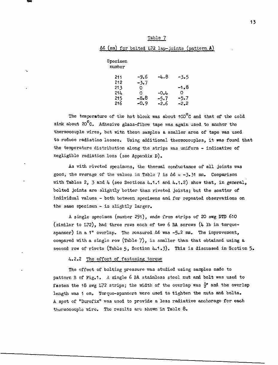
Ta]- 7
At (mm) for bolted L72 lap,'-j-oint (aerA)A
Specimennumber
211 -9.6 -4-8 -3.52'12 -3.7213 0 -1.8214. -0.4 0215 -8.8 -5.7 -5.7216 -0,9 -2.6 -2.2
The temperature of the hot block was about 1000C and that of tlhe cold
sink about 20 0 C. Adhesive glass-fibre tape was again used to anchor the
thermocouple wires, but with these samples a smaller area of tape was used
to reduce radiation losses. Using additional thermocouples, it was found that
the temperature distribution along the strips was uniform - indicative of
negligible radiation loss (see Appexndix D).
As with riveted specimens, the thermal conductance of all joints was
good; -he average of the values in Table 7 is At = -3.31 mm. Comparison
with Tables 2, 3 and 4 (see Sections 4.1.1 and 4.1.2) show that, in general,
bolted joints are slightly better than riveted joints; but the scatter of
individual values - both between specimens and for repeated observations on
the same specimen - is slightly larger.
A single specimen (number 291), made from strips of 20 swg DTD 610
(similar to L72), had three rows each of two 6 BA screws (4 lb in torque-
spanner) in a I" overlap. The measured AU was -5.2 mm. The improvement,
compared with a single row (Table 7), is smaller than that obtained using a
second row of rivets (Table 5, Section 4.1.3). This is discussed in Section 5.
4.2.2 The effect of fastening torque
The effect of bolting pressure was studied using samples made to
pattern B of Fig.1. A single 6 BA stainless steel nut and bolt was used to
fasten the 18 swg L72 strips; the width of the overlap was 1' and the overlap
length was I cm, Torque-spanners were used to tighten the nuts and bolts.
A spot of "Durofix" was used to provide a less radiative anchorage for each
t.hrmocouple wire. The results are shown in Table 8.

TEble 8
AZ (mm) for bolted L72 lap-joints (pattern BD
Specimen Torquenumber 1b in
411 1.7 0.9 1.1 0.1 0.7412 2.0 0.2 0.3 -0.2 0413 3.0 -0.3 -0.2 -1.4 -0.5
In the experiment marked *, the top block temperature was about 2000C
compared with about 1000C for the other three experiments: in all experiments
the cold sink temperature was about 200C.
The results show that increasing the bolting torque increases the
thermal conductance of the lap-joint, that is apparently the opposite effect
to that obtained with increasing the riveting pressure (see Section 4.1.1).
This is discussed in Section 5.
In a later experiment two specimens, made to pattern A of Fig.1, were
each fastened with two 6 BA stainless steel nuts and bolts using a 9 lb in
torque-spanner - the breaking torque is sligItly greater than 10 lb in. A
slight distortion of the strips to form a slight surface depression around the
fasteners was produced. The appearance was similar to that produced by under-
set riveting. The measured values of A6 are sbh.,, in Table 9.
Table 9
AZ (mm) for bolted L72 lap-joints (pattern A)- high torque
Specimen 9 lb in 3 lb innumbev
271 4.7 5.3272 6.0 5.4
Comparison with Table 7, shows that the use of a 9 lb in torque-spanner
produces a poorer contact than 4 lb in. Unfastening the bolts and re-tightening
to 3 lb in did not improve the contact (last column of Table 9) suggesting
that the effect of the high torque was to produce a permanent deformation.
4.3 Effects of surface hardness and roughness
4.-3.1 Bolted L70 lap-joints
L70 material is essentially unclad L72. The Brinell hardness is 125
compared with 16 for pure annealed aluminium. From the discussion in Section i.,

15
on the microjunctions that form the metallic conduction paths for heat
transfer between the two strips of a lap-joint, it is to be expected, for a
given contact pressure, that t14 soft aluminium cladding of L72 sheet would
lead :;o a larger area of true z-ontact, and hence a lower thermal resistance,
? than occurs with L70 (see Section 5). Comparison of At obtained with L70
7 and L72 specimens confirms this.
The values of At (mm) obtained with 3 cm wide lap-jointed strips of
18 swg L70 are given in Table 10; each joint (pattern A of Fig.1) wae
fastened with two 6 BA stainless steel screws and nuts using a 4 lb iL
torque-spanner; the overlap length was I".
Table 10
AL (mm) for bolted L70 lap-joints
Specimen 71number
311 2.9 3.4 3.3 3.331 2 1.4 0 0.5 0.9313 1.0 0.5 0.9 1.4J314 -1.0 -0.6 -0.5 0.5315 -0.5 0.5 0.5316 1.0 1.9 0.5 2.9
In Table 10, the first 4 columns of results are for successive experi-
ments; between runs the apparatus was cooled to room temperature, air was
admitied and the apparatus re-evacuated. The average of all values in these
4 columns is At = 1.06 mm. Comparison with the average value, At = -3.31 mm
(Section 4.2.1) obtained with similar lap-joints of L72, shows the increased
thermal conductance resulting from the aluminium cladding.
On two of the specimens (numbers 313 and 315), the screws were slackened
after the second experiment and re-tightened gently; a torque-spanner was not
used - the estimated torque was about 2 lb in, but certainly less than the
g original 4. lb in. The effect of this, shown in the columns marked by J, was
to increase At slightly. In later experiments (see Section 4.2.2) Lhe effect
of bolting torque was studied more carefully.
In addition, the length of overlap for two specimens (numbers 314 and
316) was reduced from I" to -" by removing 5/16" of the unfastened free end.
16V
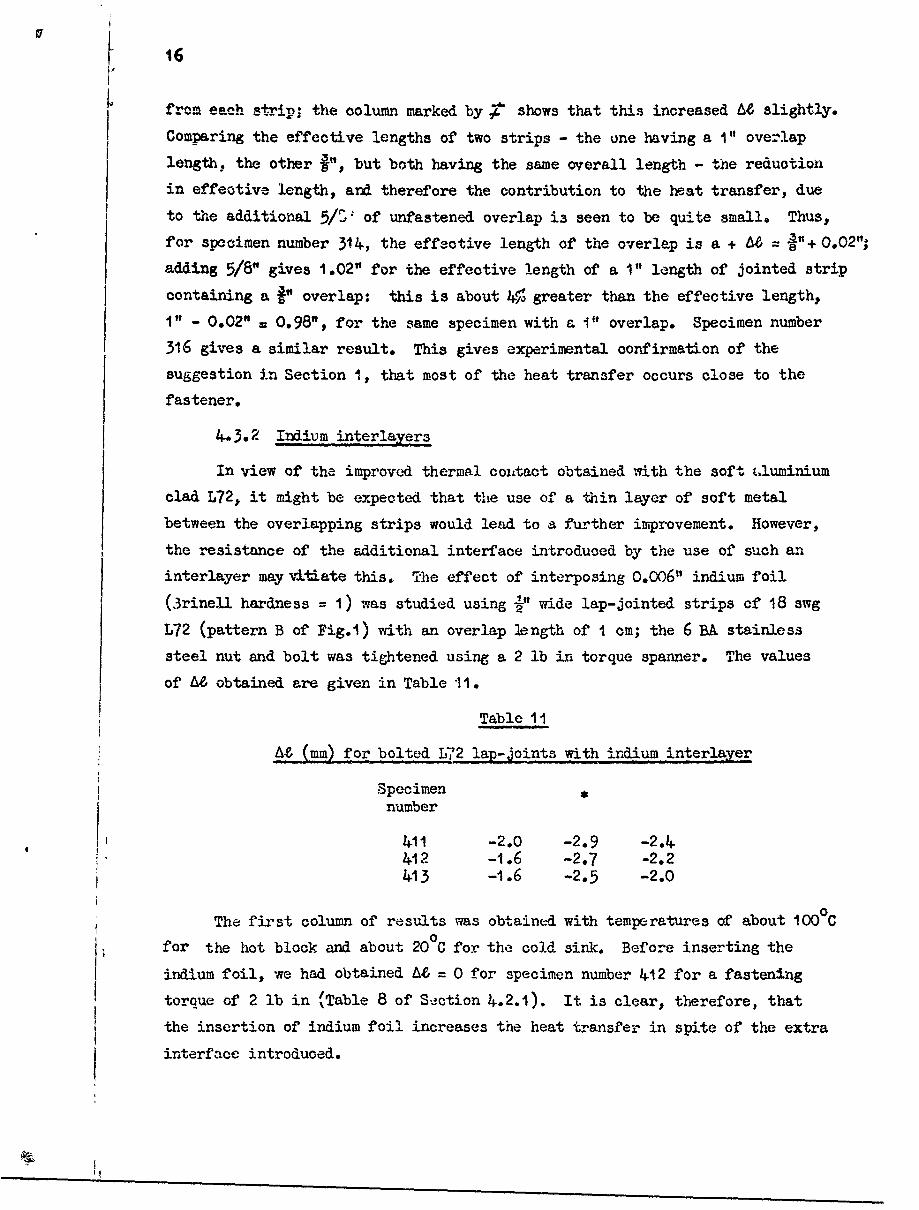
from each strip; the column marked by • shows that this increased U, slightly.
Comparing the effective lengths of two strips - the one having a I" overlap
length, the other •", but both having the same overall length - the reduction
in effective length, and therefore the contribution to the heat transfer, due
to the additional 5/C? of unfastened overlap is seen to be quite small. Thus,
for specimen number 314, the effective length of the overlap is a + 6= 0.02";
adding 5/8" gives 1.02" for the effective length of a I" length of jointed strip
containing a P" overlap: this is about 4o greater than the effective length,
I" - 0.02" = 0.98", for the same specimen with a I" overlap. Specimen number
316 gives a similar result. This gives experimental confirmation of the
suggestion in Section i, that most of the heat transfer occurs close to the
fastener.
4.3.2 Indium interlayers
In view of the improved thermal coultact obtained with the soft cluminium
clad L72, it might be expected that the use of a thin layer of soft metal
between the overlapping strips would lead to a further improvement. However,
the resistance of the additional interface introduced by the use of such an
interlayer may vitiate this. The effect of interposing 0.006" indium foil
(3rinell hardness = 1) was studied using -" wide lap-jointed strips of 18 swg
L72 (pattern B of Fig.1) with an overlap length of I cm; the 6 BA stainless
steel nut and bolt was tightened using a 2 lb in torque spanner. The values
of Aei obtained are given in Table 11.
Table 11
M& (mm) for bolted L721 la-joints with indium interlayer
Specimen *
number
4.11 -2.0 -2.9 -2.4+4.12 -1.6 -2.7 -2.24.13 -1.6 -2.5 -2.0
The first column of results was obtained with temperatures of about 1000C
for the hot block and about 20°C for the cold sink. Before inserting the
indium foil, we had obtained A6 = 0 for specimen number 4.12 for a fastening
torque of 2 lb in (Table 8 of Section 4.2.1). It is clear, therefore, that
the insertion of indium foil increases the heat transfer in spite of the extra
interface introduced.
17
'4.
Increasing the temperature of the hot block to about 1 900C, and the
indium to about 1300C improves the joint conductance lcolurwu of reults marked
by *) and part of this improvement i3 retained on reducing the hot block
temperature to about 100 C again (final column). The possibility that thisimprovement is due to some diffusion and alloying or welding is supported
by the signs of adhesion that were found on dismantling one of the specimens.
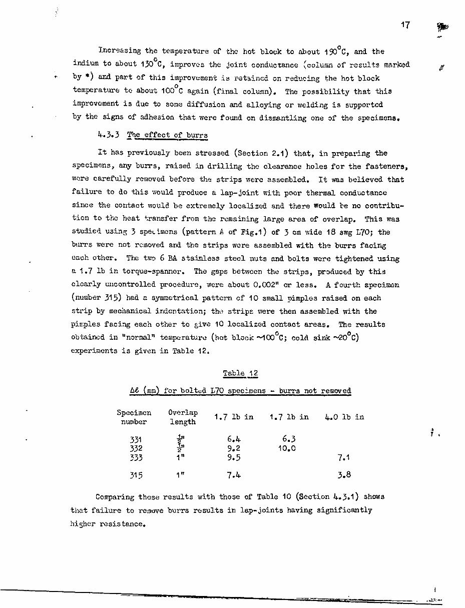
4.3.3 The effect of burrs
it has previously been stressed (Section 2.1) that, in preparing thespecimens, any burrs, raised in drilling the clearance holes for the fasteners,
wore carefully removed before the strips were assembled. It was believed that
failure to do this would produce a lap-joint with poor thermal conductance
since the contact would be extremely localized and there Would be no contribu-tion to the heat transfer from the remaining large area of overlap. This was
studied using 3 speLimens (pattern A of Fig.1) of 3 cm wide 18 swg L70; theburrs were not removed and the strips were assembled with the burrs facing
each other. The two 6 BA stainless steel nuts and bolts were tightened using
a 1.7 lb in torque-spanner. The gaps between the strips, produced by thisclearly uncontrolled procedure, were about 0.002" or less. A fourth specimen
(number 315) had a symmetrical pattern of 10 small pimples raised on each
strip by mechanical indentation; tho strips were then assembled with the
pim.ples facing each other to give 10 localized contact areas. The results
obtained in "normal" temperature (hot block -100°C; cold sink -20 0C)
experiments is given in Table 12.
Table 12
t6 (mm) for bolted L7O specimens - burrs not removed
Specimen Overlap 1.7 lb in 1.7 lb in 4.0 lb innumber length
331 b,, 6.4. 6.3332 33'332 2 9.2 10.0333 1" 9.5 7.1
315 1" 7.4 3.8
Comparing these results with those of Table 10 (Section 4.3.1) shows
that failure to remove burrs results in lap-joints having significantly
higher resistance.

18
l4.4 Miscellaneous factor.-: electrically insulating joints
in the transfer of heat between the strips of a bolted lap-joint, there
is, in addition to the metallic conduction paths formed by the microjunctions
at the interface, a path through the head of the screw, its shank and the nut.
In order to estimate the rela+1.ve importance of this route, a few specimens
with insulated screws were tested. Later, specimens having insulating inter-
layers were used (a thermally conducting, but electrically insulated, joint
is perhaps relevant to the attaching of transistors to their heat sinks). In
these experiments, the specimens were all 3 cm wide, 18 swg L70, with I"
overlap (pattern A of Fig.i).
The effects of interiayers of anti-corrosion fluid and of high emissivity
paint were also st'adIed.
4.4.1 Insulated screws
Specimen 321 had enlarged holes to accommodate thin sleeves of silicone-
rubber covering the shanks of the 6 BA stainless steel screws. Ceramic
washers wtre placed under the nut and the head of the screw to increase
considerably the thermal resistance of the conduction path via the fastener.
This spacimen was compared, in two successive experiments, with two specimens
(322 and 333) having normal 6 BA clearance holes and non-insulated screws;
the estimated bolting torque was t 2 lb in. In a third experiment (marked
by 7), the ceramic washers were removed from specimen 321 and the three
specimens were re-assembled using a 1.7 lb in torque-spanner. The results
are shown in Table 13.
Table 13
A (mm): heat transfer via the fastener
Specimen
number
321 2.9 2.3 4..
322 1..4 1.8 1.14
333 1.5 0.8
The results are not conclusive; but the smallness of the difference in
AZ suggests that conduction across the interface is much more effective than
that via the fastener.

19
4.4.2 Electrically insulated lap-joints
The values of U& obtained in experiments with electricall insulatedjoints are given in Table 14.
Table 14
Electricallv insulating joints
Specimen Torquenumber screws lb in interlayer ti (mm)
312 nylon -1 none 15.9313A nylon - none 7.0
313 nylon -1 fluon 37.6321A steel 4 mica 73.2321C steel 3 mica 77.13-IB steel 4 anodized Al 8.2
The stainless steel fasteners were electrically insulated from the L70
strips by having mica washers under the nuts and screw-heads and by passing
through enlarged clearance holes without touching. Both the fluon tape and
the mica interlayers were 0.004" thick. With specimen 321B, the insulating
interlayer consisted of two strips of anodized aluminium (3.2 cm x 1.1 cm,
thickness 0.022"; anodic oxide coating 0.0001") placed each side of the line
of the bolt-holes. The eleotrical resistance of the insulated joints was
greater than 20 MO.
The results show that the clamping load available with nylon screwsis inadequate to provide good thermal contact between L70 strips, and that for
producing high thermal conductance with electrical insulation, anodic aluminium
oxide coatings are much better than mica interlayers.
4.4.3 Anti-corrosive jointina compound
The effect of anti- corrosion fluid ("Celloseel") was studied usingspecimen number 223. Two 3 cm wide, undrilled, strips of 20 swg L72 were
coated with fluid and placed together to form a lap-joint with a 1" length
of overlap. The joint was pressed to-ether under a I lb load and air-dried
for 18 hours at room temperaturu, followed by 25 hours at 60°C. The electrical
resistance of the joint was .few ohms - not high enough, perhaps, to preclude
the possibility of there being some slight metallic contact through the layer
of compound.

I
20
Tested under "normal" conditions, A6 was -8.1 mm and -8.4. mm in
-uccessive experiments - the highest thermal conductance joint observed.
Specimen 223 was the ~ ~mpl��.t-tedin=o+ A nh i.. •ated fastenex s were
not used; it was therefore, the only joint for which one might expect uniform
thermal properties over the whole of the interfacial area. The value of Z/a,
corresponding to U = -8.1 mm, is 0.68. Hence, we have, using the analysis of-1 -2 -
Appendix C and Fig.8, h a 0.08 cal sec cm deg C-1 for-1 -1 -1
k=1/3 cal seo cm deg C
Thus this relatively low value of heat transfer coefficient produces a
joint with good thermal conductance with Zo/a = 0.68; Fig.8 shows that, for
z > 2 (say),quite large increases in h ý'educe y/a only slightly; even for
h = o, Zo/a is reduced to only 0.5.
4.4.4-. The effects of paint layers
The dominant mcde of heat transfer inside a satellite is by radiation
(see Section I). With highly reflecting aluminium surfaces, radiative heat
transfer coefficients are small. The emissivity can be increased conveniently
by using suitable paincs. At about room temperature, the maximum of the
radiation intensity occurs at a wavelength of about 10 ýi; for such long wave-
lengths the emissivities of paints are high and not strongly dependent on the
particular colour of the paint.
The thermal conductance of 4 painted specimens was measured in order
to assess the effects of lap-joint assembly after painting - a possibility
that might arise if electronic packages in a satellite are changed.
The specimens were made to pattern C of Fig.1 (length of overlap 5/8"):
141, wide strips of 20 swg L72 were fastened with three 6BA stainless steel
screws and nuts, tightened with a 3 lb in torque; only one strip of each
specimen was painted, the other was unpainted.
The paints used were to DTD 5555 and were supplied by Cellon-Docker,
Kingston-on--Thames. An etch-priming coat (sL.5539 primer + SL.5460 catalyst)
was sprayed onto the freshly degreased strips, air-dried for 4 hours and then
stove-dried for I hour at 800 C. On top of this, a dcuble-track, gloss white,
finishing coat (SL.5459 gloss white paint + SL,5460 catalyst) was applied.
This coat was also air-dried for 4 hours and stove dried at 800 C for I hour.
The total thickness of the dried paint film was 0.O04".
The painted strips of specimens 261 and 262 were masked for painting
so that two strips of paint, parallel to the line of bolt holes,were made on

each strip. Removal of the masking tape produced "steps" at the edges of
the paint film. When the specimens were assembled these steps came just inside
the overlap area. The central region of" the overlap wa3 free of paint so that
metallic contact was made where the screws were tightened:
The values of U& obtained in "normal" temperature experiments are
listed in Table 15.
Table 15
At (mm) for painted specimens
Specimen M (m)number
261 0.8262 1.2
263 18.3264 16.2
The results show that a continuous film of paint increases considerably
the thermal resistance of the interface, Comparing these results with those
of Section 5.1, for riveted L72 to the same pattern, shows that stripes of
paint, that allow metallic contact in interfacial regions close to the
fasteners, affect the thermal conductance only sli-ghtly.
5 DISCUSSION
In this section, the results of Section 4 are discussed in terus of
the model of interfacial metallic conduction given in Section i, and the
influence on it of using localized fasteners.
,e will first estimate the area of real contact for the specimens of
Section 4.3.1 (L70; pattern A). As regards the friction between threads,
it was found, for a 6 Bk nut and screw, that a torque of about 1.5 lb in is
required to lift a 100 lb load hanging vertically from the screw. Hence
load (lb) = 60 x torque (lb in)
after making a small allowance for the friction of the bearing surfaces when
the two sheets are bolted together; i.e. for a torque of 4 lb in the-2load = 240 lb =108 kgm. The Brinell hardness of L7O is 125 lkgm mm;
22
hence, neglecting work-hardening of the deforming asperitice, the orea o" real
contact is probably of the order of Im per bolt - a very small fraction of2the 760 mm overlap area. For aluminium-clad L72, the area of real contact
2is a few mm per bolt; the Brinell hardness of annealed aluminium is 16, but
may perhaps be doub), b iy work-hardening.
Comparison of the results for L72 (Table 7, Section 4.2.1) and L70
specimens (Table 10, section 4.3.1) shows that the presence of aluminium
cladding reduces the thermal resistance. A similar reduction is obtained
..2(see Section 4.3.2) by interposing a thin layer of indium (hardness- lkgm mm
but in this case the situation is complicated by the introduction of an extra
interface.
No systematic study was made of the effects of surface finish: all the
specimens tested, except those of Section 4.3.3, had surfaces in the "as
received" condition; however care was taken to ensure that the surfaces were
not scratc;hed or damaged. Apart from effects due to the dependence of hard-
ness cn plastic strain, the area of real contact for a given load is indepen-
dent of the number of contact points - the product of hardness and area is
equal to the load. Comparison of the results obtained with specimens having
burrs and the dimpled specimen (Section 4.3.3) with those for similar
specimens with burrs removed (Section 4.3.1) shows that gross surface rough-
ness produces high resistance joints. This is consistent with the generally
accepted predictions and experiments that a lower thermal resistance is obtained
with a large number of small area contacts, i.e. the conductance increases
with the sirface finish.
In Section I it was suggested that the fastening of lap-joints With
rivets or bolts would produce intimate contact only in localized regions
close to the fasteners, and that, in more remote regions of the overlap,
the metallic contact and hence the interfacial heat transfer in the absence
of radiation andfluidconduction would be poor; the use of excessive closing
pressure would distort tne strips and cause thorm to separate away from the
fasteners. It is therefore expected that gradually increasing the closing
pressure would first improve, then produce an optimum, and finally worsen the
joint conductance; that an increase in the overlap area would cause only a
slight improvement; that interposing an insulating layer of paint, in regions
away from the fastenetrs, would cause onLly a sY "ht worsening; and that the use
of multiple rows of fasteners would enable a greater fraction of the overlap

23
area to contribute effectively to the transfer of heat across the interfaoe,
In general, the results of Section "I suport these predictions.
With rivetcd specimens there is visual evidence of surface depressions
around the rivets; this distortion is probably not due to the tension in the
rivet itself, but to pressmres involved in the riveting process. CompEarison
of Tables 3 and 4. suggests that the optimum riveting pressure is about that
of underset or normally set rivets. Table 4. also shows that a change of
uverlap area has no effect on At, suggesting, for closing pressures sufficient
to produce visible surface deformation near the rivet, that the strips are
separating. Table 5 shows that a double row of rivets produces a significant
improvement.
With bolted specimens, there is a gradual improvement of thermal contact
with bolting torque (Table 8); the 4 lb in torque used for the results of
Table 7 is probably close to the optimum: an excessive 9 lb in torque
(Table 9) produced visible deformation and a joint of poor thermal contact.
(In view of the excessively large value of At, this result should, perhaps,
be discounted; the results obtained after slackening the bolts and retighten-
ing to 3 lb in suggests permanent distortion of the specimens.) Table 10
shows a 4¶,• increase in M6 for a 5/8" reduction in the length of overlap;
it is concluded that with a 4 lb in bolting torque there is a small contribu-
L tion from an extra overlap, in comparison to a zero contribution with visibly
deformed rive.ted specimens. The effect of paint at the edges of the overlap
a.-ea (Table 15) again suggests a small, but greater than zero, contribuition
from an extra overlap. As with rivets, multiple rows of bolts (Section 4.2.1)
prvduce a significant improvement in joint conductance.
The thermal conductance of the joints inureases with temperature
(Table 2). The temperature of the centre of the joint is the mean of the
hot and cold block temperatures, i.e. about 600 C in a "normal" experiment and
about 11000 in a "hot" experiment. No explanation is offerred for this
observed temperature dependence of At. Hcever, the results of section 4.1.4,
and of Tables I and 8: show that the effect is reversible; no permanent
increase in conductan3e results from the Uigher temperature. This suggests
that the softening temperature of the deformed asperities is above 110°C
and that, even in long times of order 30 days, there is negligible thermall
movement of atoms producing a decrease in hardness and an increase in
contact area. With indium interlayers (section 4.3.-2) part of the
increased heat-conduction in a "hot" experiment is retained in a subsequent
"normal" experiment.

24
L It is clear from the definition (see Section 3) of the "additional
length" parameter that the value of AU should be specific to the particulargeometry of the lap-joint. Thus, for example, Table 5 shows thatt ̂is a
function of the number of rows of fasteners used; it is likely that At
depends also on the sheet thickness and on the size of the fasteners used -
experimental variables not included in this work.
CONCLUSI ONS
The thermal behaviour of riveted and bolted lap-joints of aluminium
alloys (L70 and L72) in vacuum can be summarized as:-
(a) the dominant mode of interfacial heat transfer is by metallic con-
duction; the contributions from radiation and gaseous conduction are negligible
for low emissivity aluminium surfaces in pressures below 10-4 torr
(Appendix D).
(b) most of the heat transfer occurs close to the fasteners; the
thermal contact in ovtrlap regions away from the rivets or bolts is poor
(Sections i and 5).
(o) the concept of a uniform heat transfer coefficient is invalid for
riveted or bolted lap-joints; the thermal behaviour of the lap-jointed
specimens used is better described in terms of an additional length AM, to
be added to the conduction path to allow for interfacial resistance (Section 1).
Limitations to the general use of the AU parameter are discussed in the final
paragraph of Section 5.
(d) for joints of good thermal conductance, AU 0; i.e. the effects
of interfacial resistaice and doubled thickness cancel each other; for a
perfect joint AZ = -a/2, where a is the length of ovzrlap (Section 3 and
Appendix C).
(e) to produce thermally good joints, the mating surfaces should be
flat, and free from scratches and gross surface irregularities; burrs raised
in drilling clearance holes for bolts or rivets should be carefully removed
(Section 4.3.3).
(f) standard riveting techniques to pa-s standard visual inspection
for mechanical soundness as practised by the aircraft industry (Appendix A)
produce joints that are thermally good (Section 4.1).
(g) good joints are also produced by bolting provided that the bolts
are tightened properly, but not excessively (Section 4.2).
25
(h) an improvement in thermal conductance is obtained if multiple rowsof fasteners are used (Sections 4.1.3 and 4.2.1).
Wi) the thermal contact is improved if the aluminium alloy sheets are
clad with pure aluminium (Section 4.3.1).
(j) the thermal conductance increases with temperature (Table 2); temper-ature cycling and prolonged storage at 1I0°C have no effect (Section 4.1.4).
(k) a thin indium interlayer improves the thermal contact and a further
improvement is obtained after heating to 110 0C (Section 4.3.2).
(1) a single experiment suggested that a thin film of anti-corrosive
jc inting compound ("Celloseel") may not be harmful and may be beneficial
(Section 4.4.3).
(m) insulating interlayers of fluon tape, mica and paint, preventmetallic Qontaot and reduce the thermal conductance of the joint (Sections
4.4.2 aWd 4.4.4).
(n) anodio aluminium oxide coatings can be used to produce electrically
insulating joints of only slightly reduced thermal conductance (Section 4.4.2).
ACIGJOWI1EDGEMENTS
The authors are grateful to Mr. Blondstein (British Aircraft Corporation
Ltd., Stevenage) and his colleagues on the U.K.3 satellite project, for their
helpful co-operation, and to their skilled craftsmen for riveting and painting
some of the specimens.

1 i26
A pendix A
R -IVETING - STANDARD AIRCRAT PRACTISE
Aluminium alloy rivets are usually* made from L86, which contains 215copper. Since this alloy does not age-harden appreoiably, the rivets can be
used from stock without re-amnealing. Rivet holes are jig-drilled about
0.002" oversize and burrs are removed. The sections are clamped together and
rivets are inserted. With thin sheets the techni.que of "reaction riveting"is
used; a small metal anvil ("dolly") is held against the rivet shank while a
second operator presses a hand "gun" lightly against the pre-formed head of
the rivet. The hand-gun has a cylindrical steel hammer shaft, pneumatically
vibrated along its axis. Under the impact pressure of the vibrating hammer,
the rivet shank squashes down and spreads to form a barrel-shaped cheese head
against the dolly. The operator, by experience, adjusts time and pressure to
produce a uniform size of head. Maximum diameter can be checked by a socket
gauge, which should be a snug fit.
More precise mechanical control is obtained by machine-riveting, in
which the rivet is squeezed by the steady pressure of a pneumatic plunger;
the pressure and stroke are adjustable. This process can be used only on
sections of work small enough to be manipulated between the jaws of the
machine.
Riveting pressure is normally adjusted to give a result of the type B
in Fig.4., in which the cheese-head diameter is 500/• larger than the shank
diameter. Inadequate pressure produces the "underset" rivet (type A) and
excessive pressure causes "oversetting" (type C).
When access to both sides of the work is not available a technique of
blind, or "pop", riveting is used. Pop-rivets have a hollow shank which is
expanded by the wedge action of an :nner core. This method tends to be more
variable thsn the previous mcthocis and is avoided when possible; it has not
been included in this investigation.
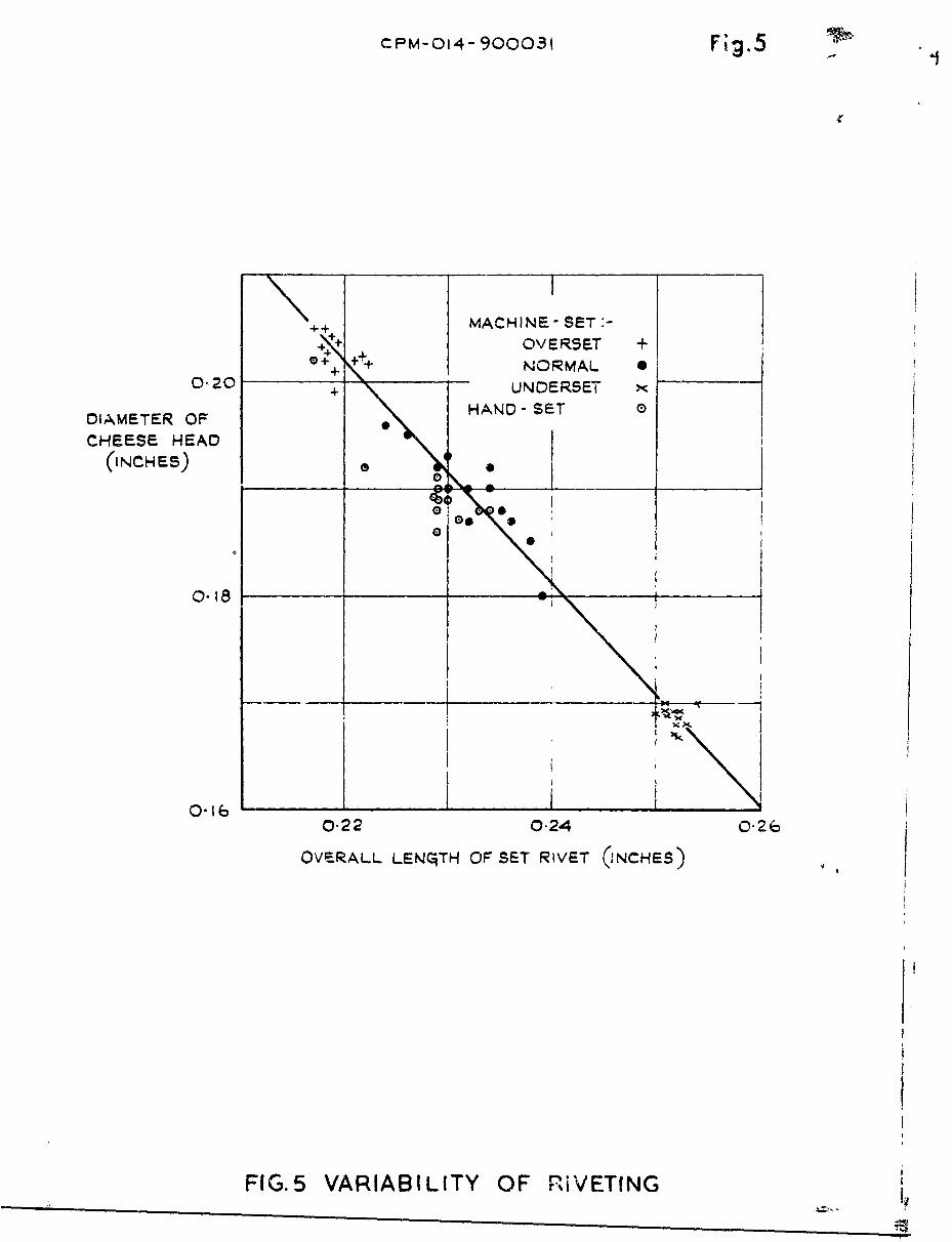
For the experiments reported in Section 4.1. three batches of machine-
riveted specimens were prepared, corresponding to types A, B and C of Fig.4.
A fourth batch was made by standard hand-riveting technique, using the pneu-
matic gun. Fig.5 shows a linear relation between the cheese-head diameter and
the overall length; it also shows that, although hand-rivetin- is more
variable than machine riveting, the variation rarely exceeds 5%.
* Highly stressed joints may use the ,41tronger L37 alloy, containing 4% copper.These rivets must be annealed shortly before use.

27
Appendix, B
Thermocouples
The junction obtained by spot-welding a fine wire of chromei or alumel
onto a surface cf alu~minium is intrinsically weak. Since these alloys have
a much higher resistivity than alumainium, they tend to melt completely before
the aluminium surface gets hot. If the tip of the welding electrode is flat,
the wire collapses under it forming a thin wafer of negligible strength. By
use of a rounded or cylindrical electrode surface, a more gradual change of
wire thickness, with improved mechanical strength, is obtained.
The wires to be welded should be free from surface oxide; ordinary
"black" wire can be cleaned with carborundum paper, but it is more convenient
to use bright drawn wire*. Alumel tarnishes slow'ly in air, but the thin
surface film is easily removed. Oxidation of base metals is generally con-
trolled by reducing welding time to a minimum: we therefore tried a
capacity power supply, with a discharge time of about 10 m sec ; however,
excessive &plashing occurred, preventable only by using excessive electrode
pressure (,a 20 lb load): better results were obtained with a thyratron-
controlled power supply, using a longer weld-time (40 m sec = 2 cycles) and
normal electrode pressure.
These welds were reasonably strong in tension, but still rather weak
under bending stresses. Additional mechanical support was provided by
anchoring each wire to the edge of the specimen. For the earliest specimens,
a small strip of adhesive glass-fibre tape was used; with later specimens this
was replaced by a spot of "Durofix", to reduce radiation losses (see Appendix D).
In order to control the location of the hot junctions (see Fig.6, lines
were scribed across the specimens at accurately measured intervals. A pair
of wires (diameter 0.012" for the earliest specinens; 0.007" later) was laid
end-to-end along the scribe-lines, and individually welded. The scribe-lines
were perpendicular to the long axis of the specimens, that is, perpendicular
to the direction of heat flow, so that the thermal emf's would be unaffected
by the intermediate section of aluninium at each junction.
* Obtainable, for example, from A.G. Scott Ltd., '!anchester.

28
Appendix C
THEORY OF ThE LAp-J0Tr.D mrlTl- Ti, TV." STMnAD S
EVCT.TrnTMG PADTATI ON ATD GhS-C01NDUCTION
As discussed in Sections I and 5, the use of localized fasteners pro-
duces non-uniformities in the thermal resistance across the interface of a
lap-joint. A simple description of the thermal behaviour of such joints is
provided by the concepts of effective length Zol and additional length M&
due to thermal resistance, proposed in Section 3. However, for the case of
uniform thermal resistance, the results can be expressed in terms of the usual.
heat transfer coefficient h, i.e., the heat flux per unit temperature difference
across the interface of the overlapping strips. In this appendix, we give,
since it is not included in the standard reference books, a theory for this
ideal case of constant h.
The conduction of heat in lap-jointed strips (width u; thickness v;
thickness 2v in the overlap region -a >, x 5 -a - see Fig.7) is essentially
one dimensional for large thermal conductivity k, if v is small enough. In
the absence of radiation end at pressures low enough for gas-conduction
losses to be negligible, the flow of heat Q is, in the steady state, constant
along the specimen.
Let subscript I refer to the hotter and subscript 2 to the colder of
the two strips. For an element Zx of the overlap region, the net heat con-
ducted by one strip is equal to the heat cransferred to the other strip.
Hence, in the steady state,
•2 TI
2kvhu (T -T)
•22 1
ax
Subtracting and adding these equations, and putting M = T - T2 and = T1 + T2,
we obtain
2S2h 2 (C.2)4x "k = mkv
t o . (C.3)ax

Appendix C 29
The solutions are,
C= CeM + De-'m (C.4)
(= Ax + B (C.5)
where the constants A, B, C and D are to be found from boundary conditions.
The condition of constant heat flux gives,
Q = -kuv(.Z. -kuv (C.6)
x:ý- ja
Since the temperature versus distance diagram is symmetrical and there is no
heat flow from the free ends of the strips, we have
IN= ( - X = o . (C.7)
Differentiating equation (0.5), we obtain
aTI aT2
A (C. 8 )
and from equiations (c.7) and (C.6),
kuv K~~ a (50.9)
Differentiation of equation (C.4) gives
am T I aT2 mx -rx
-x - - -x = nCme -Dine .(C.1)aX x ax
Adding and subtracting equations (C.8) and (C.io), and using boundary condition
(C.7), we obtain
-A = D-AC = D 2m sinh (1m a))

3}0 Appendix G
Let T be the avornlc te•0wr:'.turc at x 0 0; thra.t is
T + T
From symmetrfj, T0 = a + T2(x=a/2)T
also, and is thus readily derived from observed temperatures. Substitution
in equation (C.5), for x = 0, gives
B = 2T . (C.12)
The complete solutions are, therefore,
FI ~cosh mx )T = T 1 + AxF1 "h
o 0 L mx sinh (2-ma) a
(C.13)Fo'cosh rTx
ji
aITwhere A, from equation (C.9), is the temperature gradient aT in either strip
away from the overlap region.
.o calculate h, we substitute, in equations (C.13), the temperature
drop AT across the lap-joint, deduced from observed temperatures using
equation (3) of Section 3. As before, division by -aT/ax gives the "effective
length" Z° of an actual length a of over]ap. Hence,
-0 ( I + b] = + coth_- a . (c.-i4al
Note that for a perfect "ideal" joint,
h oo
-Im a 0o
a 2

,.p-_nndix C
that is, the effective length is half the actual length - the expected result
since the thickness is doubled at the overlap. For a value of eo/a, derivedfrom experiment using equation (5,zg.8, in" which •(i + oth z/z) is plotted
again6t a/ a can be used to -solve equation (c.14) graphically for m; the
heat transfer coefficient h is then given by h = k kum2 (equation (C.2)).
Fig.8 also shows that, for 6/a < I, to is not strongly dependent onh (zm h). From an engineering point of view, this implies that, when Z
0
has been reduced to u0 a, only slight t ivantage is obtained by increasing
h further; for example, the results of Section 4.4.3 show that an increase offrom 0.08 cal sec- cm-2 deg C-1 to infinity ruduces Zo/a only slightly -
from 0.68 to 0.5.

32
Appendix .i
TE EFFECTS OF RADIATION AND GASEOUS CONDUCTION
The steady state temperature distribution, for heat flowing through a
long bar from which the sideways heat losses are proportional to the tempera-
ture difference (T - TO) between the bar and its surroundings, is describedS~15,16in the standard theoretical treatments of heat conduction . For the
particular case of a bar of cross-section uv, thermal conductivity k, and
surface heat transfer coefficient e, we have, in the steady state
a2Tk~ u+v (T To0) (Doi)ax
Writing e for (T - To), :;e obtain
2=2 (u + V).e = n e. (D.2)
uv kax
The solution is
6 E Ee"n +F'e' (D-3)
where the constants E and F are to be found from boundary conditions.
In the absence of lateral heat losses, the temperature varies linearly
with distance along the bar; but if e is finite the temperature profile is
curied. The curvature can be studied by observing the tenperatures 81, e2
and 6 at three points on the bar. If the distance between consecutive points3
is equal (say b), we have, from equation (D.3),
+ e )3 = (nb -ao=2(n +e = cosh nb = w(say) (D.1)
Hence nb= cosh- = in [w + /i2--] (D.5)
In order to estimate the effects of radiation and gas-conduction on the
experiments of Section 2.3, we consider a 25 cm length of unjointed 3 cm x I/10 cm
strip of aluminium alloy ( k 1/5 cal sec 1 cm 1 deg C-) clamped between the
two blocks of the apparatus.

Appendix D
The radiant heat flux is given by 3tefan's law,
T T - 0 ) (D.6)
in which 0 = 5.72 x 10-A2 watts cm deg and E is the total emissivity -
or emissive power expressed as a fraction of a"black body" - of the surface.
Hence the heat transfer coefficient for radiation is,
=1 4ET 3 (D.7)
which, for a highly rýflecting metal surface (E - 10-t say) at 330 0 K (the mean
temperature of the experiments), gives
.5-1 -2 -1
CI !- 2 x 10⁻⁵ cal sec cm deg C • (D.8)
For air at 5 x 10⁻⁵ torr (the residual pressure in the apparatus) therate of molecular impacts is about 2 x 1o16 sec ;tking the specific
heat as 6 cal mole"I, or 10-23 cal molecule-1 (5/2R for a diatomic gasplus 4R to take account of the higher impingement rate of the fazter molecules)
and assuming frfe molecule flow and an energy accommodation coefficient of
unity, we obtain for the surface heat transfer coefficietit for gaseous con-
duction in a pressure of 5 x 10⁻⁵ torr,
-1 -2 -1 D9
C2 = 2 x 10⁻⁷ cal sec cm degC ,(
which is small compared with the coefficient e1 for radiation.
Putting e = 2 x 10⁻⁵ in equation (D.2) we obtain n = 12 x , or
n = 3.5 x 10⁻². Hence, for a separation of d = 3 cm between thermocouples,nd z0 .1 and cosh nd= 1.005, so that, for e2 400C, the departure from
linearity [½(6I + 03) - 02] is about 1/5°C, which is about the limit of
sensitivity of the thermometry used (see Section 2.3). In experiments,
using specimens with additicnal thermocouples, no curvature of the tempera-
ture profile was detected.
A more sensitive experiment is to raise both copper blocks of the
apparatus to the same tepac.'ature (-40 0C above ambient, say) and to

S34 Appendix D
observe how much cooler the centre of an unjointed strip is. If th I le t a-tures are e at the two ends, x = v, and e0 at the cent.. of. the strip. we
have, from equation (D.3)
cosh n =
or
- = (cosh me. - 1) 0o (D.1O)
For 26= 20 cm, ani taking n 10 as before, we obtain nme 0.44 andcosh nri 1, giving aet - o0 4.C. In such experiments, using the earliestspecimens which had 0.012" diameter thermocouple wires supported by adhesive
glass-fibre tape, the centre was I to 1½°C cooler than the ends. This difference-*0was reduced to about ° C by using 0.007" wires supported by spots of "Durofix" -
indicating that the high emissivity of the tape and the relatively large areaneeded to provide anchorage for the wires were introducing unnecessary radia-
tion losses. This improved thermocouple technique, with the lower radiationloss, was used for the later specimens (see Appendix B); a -°C temperature
difference suggests an emissivity o£' order 1% rather than the 10% assumed inthe sums above. Thus, for the experiments described in Section 2, it is con-cluded that the heat losses from the sides of the specimens are negligible.
As regards the heat transfer in the overlap region of the lap-jointed
specimens, we will now show that, under the coneitions of the experiments,the contributions of radiation aid gaseous conduction are very much smaller
than that of metallic conduction. In most of the experiments Cia = I (see
Section 4). 4suJsmng, for the purposes of this argument, that the thermal
beh 7viowr of the interface can be described in terms of a heat tran3fer
coefficient h, unif orm over the over-lap region (see Appendix C), we have
from Fig.8,
z a = ----- aa h = 1.16S2kv
or- 10 > cal sec- cm 2 deg C-1 (D.1i)
which is so large, compared with the radiative heat transfer coefficient,
I 1 =2 x 10⁻⁶ cal sec 1 cm 2 deg C 1 for I% of black body, that, even with
multinle reflections, metallic conduction must be the predominant mode of
heat transfer.

Appendix D 35
Comparison of equation& (D.9) and (D.11) suggests that the transfer ofheat across the interface by gaseous and metallic conduction should be eoualat a prebsure of 2.5 torr. However, the assumaptions of free mole-cular flowend a uniform h, implied in this comparison, are probably invalid. Experimemtsat higher pressures indicated an increasingly significant contribution bygas-conduction to the interfacial heat transfer, but the large curvature ofthe temperature profile produced by the increased lateral losses precludedsatisfactory interpretation of experiments. In view of this, only a fewexperiments at higher pressures were attempted and their results are notreported.

36
R17 E-RETCE.S
No. Author Title, eto,.
I F.P. Bowden The friction and lubrication of solids.
D. Tabor C1areadon Press, Oxford (1950)
2 R. Holm Electric contacts handbook, 3rd edition
Springer-Verlag; Berlin (1958)
3 T.N. Cetinkale Therral conductance of metallic surfaces in contact,
M. Fishenden general discussion on heat transfer.
Proc. Inst. Mech. Engrs., ASME, p 271, (1951)
4 L.C. Laming Thermal and electrical conductance of machined metal
contacts.
Ph. D. Thesis, (University of London(1958))
5 H. Fenech Prediction of thermal conductance of metallic surfaces
W.M. Rohsenow in contact.
Trans. ASME 85, series C, (62-HT-32) p 15 (1963)
6 R.B. Jacobs Thermal conductance of metallic contacts.
C. Starr Rev. Sci. Instrum., 1L0, p 140, (1939)
7 Yu. P. Shlykov Experimental study of contact heat exchange.
E.A. Ganin Teploenergetika 8, p 73, (1961)-translation AD 430 088 (28/1/1964)
8 E. Fried Interface thermal contact resistance problem in
F.A. Costello space vehicles.
J. Amer. Rocket Scc. 32, p 237, (1962)
9 E. Fried Thermal joint conductance in a vacuum.
ASKE paper No. 63-AHGT-1 8, (March 1963)
10 T.W. McDonald Thermal contact resistance.
Trans. Eng. Inst. Canada 6, (1963)
iS W.E. Kaspareck Measurements of thermal contact conductance between
R.M. Dailey dissimilar metals in vacuum.
ASME. paper No. 64-HT-38, (August 1964)
12 W. Aron Controlling factors of thLrmal conductance across
G. Colombo bolted joints in a vacuum environment.
AS•oX paper No. 63.-WA-1 96, (November 1963)

37
RKFRENGES (Contd)
No. Auth'r Title, etc.
13 E.H. Coker A treatise on photoelasticity, 2nd Edition.
L.N.G. Filon (Cambridge University Press (1957))
14 I. Fernlund A method to calculate the pressure between bolted
or riveted plates.
Report No. 24.5, Trans. Chalmers Univo Techn.,
Gothenberg, Sweden (1961)
15 H.3. Carslaw The conduction of heat in solids.
J.C. Jaeger Clarendon Press, Oxford (194.8)
16 H.S. Allen A textbook of heat, Part 2.
R.S. Maxwell Macmillan and Co. Ltd., London (191.3)

CPM-014-900027 Fig.1
T> 10
S- - '-
I-,
-I0 0o----
I --
DOUBLE~ ROWI
Y2 I
,I_ " iQO--i --
E
NDOUBLE ROW 0 ---- - IRE0
,OH OW- - ,
F ,.1 RIVET PATTERNS OF LAP-JOINTED SPECIMENS

Fig.2 CRM-014-9000 2 8
ELECTRICALLY HEATED ML TE
HOT BLOCK ACKINq PLAýTES,
CLAMPING PLA4TES
5UjpPORT
WIATER
COLD BLOCK
EI, P HEAPPARATUS
C.PM -014-900029 Fig.3
)e2 e.
T 0I I
_____I - I I,C
! i I; II I I ,'
I 0I
N -----
kI I I I
i. I I
i ie,TEMPE ATPRR I I SPECI
iI I II ~i-- I
_ _ I I
Ii I
II I! I
II I jI
FIG. 3 TEMPERATURE PROFILE OF SPECIMENS

" . Fig.4 CPM-014-900030
A
A B C
UNDERSET NORMAL OVERSET
FIG.4 MACHINE-SET RIVETS
CPM-014- 900031 Fig.5
MA MACHINE- SET:-
+.+ OVERSET +-+ N IORMAL 0
0,20 + UNDERSET
DIAMETER OF HAND-SET 0
CHEESE HEAD(INCHES)
ole
0.18o
0.10
0.22 0.24 0.26
OVERALL LENGTH OF SET RIVET QiNCHES)
FIG.5 VARIABILITY OF riVETING

t Fig.6 CFM-04-900032
ei2 e3
HEATFLOW
I
II
FIG.6 LOCATION OF THERMOCOUPLES

CPM-o04-9ooo35 Fig.7
, 1 T,/I I
I II II I
t, II
TE ~ToTR AT1
¶I I
r 0 -.----- ) I
T2
FIG. 7 TEMPERATURE DISTRIBUTION FOR
LAP-JOINT WITH UNIFORM h

Fig.8CPM- 014-900034
+ -
2( __
0/CL
f I _ _ _
L--M
- _ _ -
cot-4H- - - 1-+