Embed Size (px)
Citation preview
INTERNATIONAL JOURNAL OF INNOVATIVE TECHNOLOGY & CREATIVE ENGINEERING (ISSN:2045-8711) VOL.1 NO.5 MAY 2011
10
Performance Evaluation and Selection of Optimal Parameters in Turning of Ti-6Al-4V
Alloy Under Different Cooling ConditionsM Venkata Ramanaa, K Srinivasulub, G Krishna Mohana Raoc,*
a: Sr. Asst Prof in Mech Engg, VNRVJIET, Bachupally, Hyderabad, AP, India.b: Asst.Prof. in MEch Engg, CMR Institute of Technology, Medchal, Hyderabad, AP, India
c,*: Associate Prof in Mech Engg, JNTUH College of Engg, JNT University Hyderabad, Kukatpally, Hyderabad-85, AP, India,
Abstract -Titanium alloys have very high tensile strength and toughness, light weight, extraordinary corrosion resistance, and ability to withstand extreme temperatures. However, the high cost of both raw materials and processing limit their use to military applications, aircraft, spacecraft, medical devices, connecting rods on expensive sports cars, some premium sports equipment and consumer electronics. Surface finish plays vital role in service life of components, to ensure a great reliability of sensitive aeronautical components, surface integrity of titanium alloys should be satisfied. Therefore, it required to optimize process parameters like cutting speed, feed and depth of cut while machining titanium components for better surface finish and also high tool life in order to reduce the tool cost. In order to reduce high temperatures in the machining zone, cutting fluids are employed in machining. Cutting fluid improves the surface conditions of the work piece, tool life and the process as a whole. It also helps in carrying away the heat and debris produced during machining. This project work deals with performance evaluation and optimization of process parameter in turning of Ti6Al4V alloy with different coolant conditions using Taguchi’s design of experiments methodology on surface roughness by uncoated carbide tool. The results have been compared among dry, flooded with Servo cut oil and water and flooded with Synthetic oil coolant conditions. From the experimental investigations, the cutting performance on Ti6Al4V alloy with synthetic oil is found to be better when compared to dry and servo cut oil and water in reducing surface roughness. The results from ANOVA shows that while machining Ti6Al4V alloy, the Synthetic oil is more effective under high cutting speed, high depth of cut and low feed rate compared to dry and servo cut oil and water conditions. The ANOVA also reveals that feed rate is dominant parameter under dry, servo cut oil and water and synthetic oil conditions in optimizing the surface roughness.
Keywords: Titanium alloy, Turning, Coolants, Optimization
I. INTRODUCTIONA. Work material
Titanium alloys are used for demanding applications such as static and rotating gas turbine engine components. Some of the most critical and highly-stressed civilian and military airframe parts are made of these alloys. The use of Titanium has expanded in recent years to include applications in nuclear power plants, food processing plants, oil refinery heat exchangers, marine components and medical prostheses. The high cost of Titanium alloy components may limit their use to certain applications. The relatively high cost is often the result of the intrinsic raw material cost, fabricating costs and the metal removal costs incurred in obtaining the desired final shape. For most applications Titanium is alloyed with small amounts of Aluminum and Vanadium, typically 6% and 4% respectively, by weight. This mixture has a solid solubility which varies dramatically with temperature, allowing it to undergo precipitation strengthening.
The difficulties involved in machining of Titanium alloys:
Higher difficulties are expected when machining Titanium alloys because of the following factors: (I) The mechanical properties, especially the hardness and the tensile stress at high temperatures (400 ◦C) (II) The differences of structure with a variable quantity of the alpha phase (III) The morphology of the transformed beta phase. (IV) High temperature strength, (V) Very low thermal conductivity, (VI) Relatively low modulus of elasticity and (VII) High chemical reactivity.
Due to the above mentioned reasons traditional metal cutting of Titanium alloys requires large quantities of cutting fluids
B. Cutting fluids:
INTERNATIONAL JOURNAL OF INNOVATIVE TECHNOLOGY & CREATIVE ENGINEERING (ISSN:2045-8711) VOL.1 NO.5 MAY 2011
11
Cutting fluids are used in metal machining for a variety of reasons such as improving tool life, reducing work piece thermal deformation, improving surface finish and flushing away chips from the cutting zone. Practically all cutting fluids
presently in use fall into one of four categories:
- Straight oils
- Soluble oils (Servo cut oils)
- Semi synthetic fluids
- Synthetic fluids
C. Various possible conditions of lubrication in metal cutting:
The high temperature and the high stresses developed at the cutting edge of the tool are the principal problems when machining titanium alloys. To minimize the problem, a cutting fluid must be applied, as a basic rule. The cutting fluid not only acts as a coolant but also functions as a lubricant, reducing the tool temperatures and lessening the cutting forces and chip welding that are commonly experienced with titanium alloys, thus improving the tool life. The correct choice of cutting fluid has a significant effect on tool life. Abundant, uninterrupted flow of coolant will also provide a good flushing action to remove chips, excellent chip breakability, minimize thermal shock of milling tools and prevent chips from igniting. Additionally, a high pressure coolant supply can result in small, discontinuous and easily disposable chips, unlike the long continuous chips produced when machining with a conventional coolant supply.
II. LITERATURE SURVEY
Manna.A et. al. [1] has presented an
experimental investigation of the influence of cutting conditions on surface finish during of Al/Sic-MMC. In this study, the Taguchi method, is used to optimize cutting parameters for effective turning of Al/Sic-MMC using a fixed rhombic tooling system. Nektarios M. Heretis et al [2] examined the surface roughness of Ti6Al4V alloy after machining in conventional machines with various tool geometries, cutting speeds and lubrication/cooling conditions. The surface roughness of biocompatible Ti6Al4V is important when this titanium alloy is used for cell growth on human implants. The result reported in this paper provides a guideline on adhesion, orientation and growth of fibroblast for the Ti6Al4V titanium alloy. Ram Cherukuri et al [3] discussed about the research and development in machining of titanium with WC/Co and PCD tools Results agree well with the
general observation that a stable, strong adherent layer forms at the interface between the tool and the chip and minimizes the dissolution-diffusion wear mechanism. S. K. Bhaumik et al [4] have made an attempt to machine Ti6Al4V alloy with wurtzite boron nitride (wBN) based cutting tools. The mechanisms controlling the wear of the cutting tool have been found to be similar to those observed in polycrystalline diamond (PCD) and polycrystalline cubic boron nitride (PCBN) tools. The results indicate that the wBN-cBN composite tools can be used economically to machine titanium alloys. A.A. Ganeeva et al [5] has focused on the manufacturing of layered material from titanium alloy. The characteristic features of the fractured specimens are studied. It has been an evident case that the surface finish of titanium alloy materials is a research topic of VITALITY. A thorough study of literature suggests the usage of processes like Dry Machining and Flooded Machining at three different cutting conditions for a better surface finish of Titaium-Ti-6Al-4V. In the present work, uncoated tungsten carbide has been selected as cutting tool material replacing the coated tungsten carbide because studies prove that uncoated tungsten carbide will enable us to get a better surface finish when compared to the usage of coated tungsten carbide.
III. EXPERIMENTAL DETAILS
A. Selection Of Control Factors And Levels:
A total of three process parameters with three levels are chosen as the control factors such that the levels are sufficiently far apart so that they cover wide range. The process parameter and their ranges are finalized based on the literature, machine operators’ experience. The three control factors selected are spindle speed (A), feed (B), and depth of cut (C). Uncoated carbide tools are used in experimentation. The control factors and their alternative levels are listed in Table 1
Table I: Control Factors And Levels
LEVEL
NUMBER
SPEED
(A) (rpm)
FEED RATE
(B) (mm/min)
DEPTH OF CUT
(C) (mm)
1 400 0.206 0.6
2 500 0.240 1.0
3 630 0.329 1.6
B. Selection of Orthogonal Array:
INTERNATIONAL JOURNAL OF INNOVATIVE TECHNOLOGY & CREATIVE ENGINEERING (ISSN:2045-8711) VOL.1 NO.5 MAY 2011
12
Selection of particular orthogonal array from the standard O.A, depends on the number of factors, levels of each factor and the total degrees of freedom.
i) Number of control factors = 3
ii) Number of levels for each control factors = 3
iii) Total degrees of freedom of factors = 6
iv) Minimum number of experiments to be conducted =7.
Based on these values and the required minimum number of experiments to be conducted (9), the nearest O.A. fulfilling this condition is L9(3
4).It can accommodate a maximum of four
number of control factors each at three levels with 9 numbers of experiments. Here the requirement is to accommodate four control factors at three levels, which can be easily done in this O.A. However, one column in this O.A. lefts empty, which is also permitted by the principles of robust design methodology. Table 2 gives the factor level fixed for the present study.
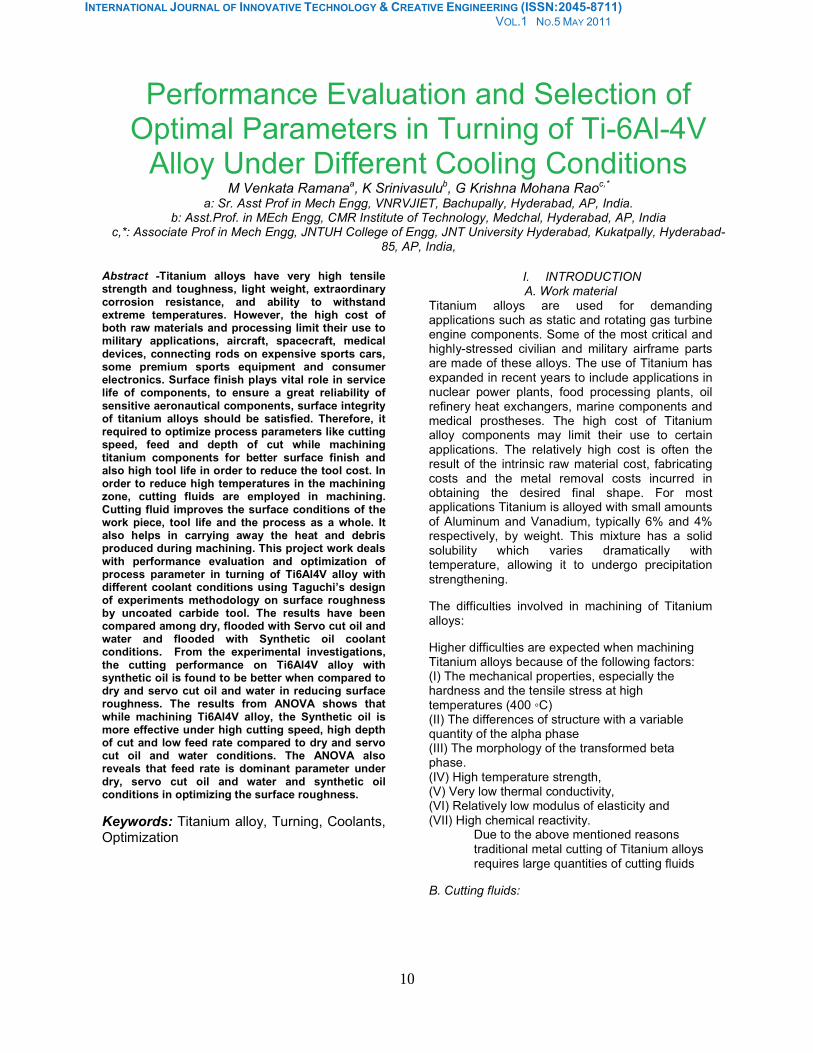
C. Experimental Setup
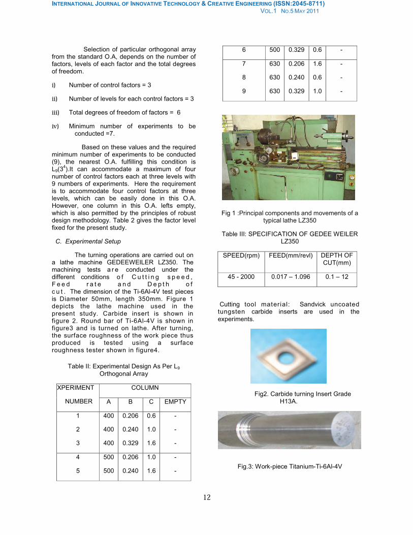
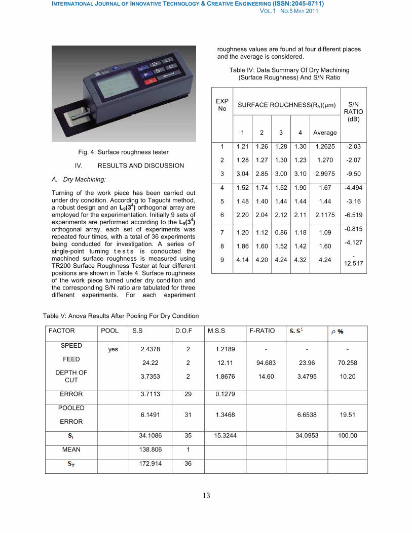
The turning operations are carried out on a lathe machine GEDEEWEILER LZ350. The machining tests a r e conducted under the different conditions o f C u t t i n g s p e e d , F e e d r a t e a n d D e p t h o f c u t . The dimension of the Ti-6Al-4V test pieces is Diameter 50mm, length 350mm. Figure 1 depicts the lathe machine used in the present study. Carbide insert is shown in figure 2. Round bar of Ti-6Al-4V is shown in figure3 and is turned on lathe. After turning, the surface roughness of the work piece thus produced is tested using a surface roughness tester shown in figure4.
Table II: Experimental Design As Per L9
Orthogonal Array
COLUMN EXPERIMENT
NUMBER A B C EMPTY
1
2
3
400
400
400
0.206
0.240
0.329
0.6
1.0
1.6
-
-
-
4
5
500
500
0.206
0.240
1.0
1.6
-
-
6 500 0.329 0.6 -
7
8
9
630
630
630
0.206
0.240
0.329
1.6
0.6
1.0
-
-
-
Fig 1 :Principal components and movements of a typical lathe LZ350
Table III: SPECIFICATION OF GEDEE WEILER LZ350
SPEED(rpm) FEED(mm/revl) DEPTH OF CUT(mm)
45 - 2000 0.017 – 1.096 0.1 – 12
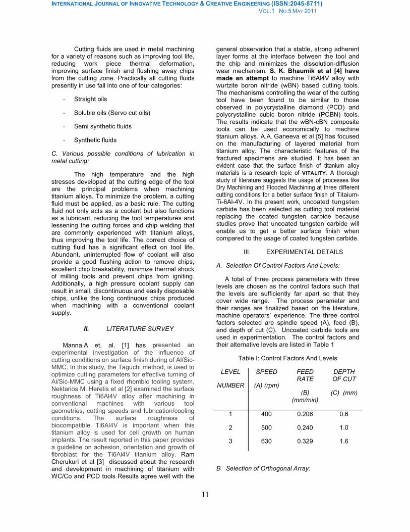
Cutting tool material: Sandvick uncoated tungsten carbide inserts are used in the
experiments.
Fig2. Carbide turning Insert Grade H13A.
Fig.3: Work-piece Titanium-Ti-6Al-4V
INTERNATIONAL JOURNAL OF INNOVATIVE TECHNOLOGY & CREATIVE ENGINEERING (ISSN:2045-8711) VOL.1 NO.5 MAY 2011
13
Fig. 4: Surface roughness tester
IV. RESULTS AND DISCUSSION
A. Dry Machining:
Turning of the work piece has been carried out under dry condition. According to Taguchi method, a robust design and an L9(3
4) orthogonal array are
employed for the experimentation. Initially 9 sets of experiments are performed according to the L9(3
4)
orthogonal array, each set of experiments was repeated four times, with a total of 36 experiments being conducted for investigation. A series o f single-point turning t e s t s is conducted the machined surface roughness is measured using TR200 Surface Roughness Tester at four different positions are shown in Table 4. Surface roughness of the work piece turned under dry condition and the corresponding S/N ratio are tabulated for three different experiments. For each experiment
roughness values are found at four different places and the average is considered.
Table IV: Data Summary Of Dry Machining (Surface Roughness) And S/N Ratio
SURFACE ROUGHNESS(RA)(µm) EXP No
1 2 3 4 Average
S/N RATIO
(dB)
1
2
3
1.21
1.28
3.04
1.26
1.27
2.85
1.28
1.30
3.00
1.30
1.23
3.10
1.2625
1.270
2.9975
-2.03
-2.07
-9.50
4
5
6
1.52
1.48
2.20
1.74
1.40
2.04
1.52
1.44
2.12
1.90
1.44
2.11
1.67
1.44
2.1175
-4.494
-3.16
-6.519
7
8
9
1.20
1.86
4.14
1.12
1.60
4.20
0.86
1.52
4.24
1.18
1.42
4.32
1.09
1.60
4.24
-0.815
-4.127
-12.517
Table V: Anova Results After Pooling For Dry Condition
FACTOR POOL S.S D.O.F M.S.S F-RATIO
SPEED
FEED
DEPTH OF
CUT
yes 2.4378
24.22
3.7353
2
2
2
1.2189
12.11
1.8676
-
94.683
14.60
-
23.96
3.4795
-
70.258
10.20
ERROR 3.7113 29 0.1279
POOLED
ERROR 6.1491 31 1.3468 6.6538 19.51
34.1086 35 15.3244 34.0953 100.00
MEAN 138.806 1
172.914 36
INTERNATIONAL JOURNAL OF INNOVATIVE TECHNOLOGY & CREATIVE ENGINEERING (ISSN:2045-8711) VOL.1 NO.5 MAY 2011
14
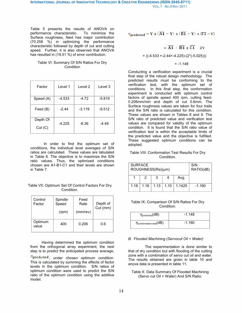
Table 5 presents the results of ANOVA on performance characteristic. To minimize the Surface roughness, feed has major contribution (70.258 %) in optimizing the performance characteristic followed by depth of cut and cutting speed. Further, it is also observed that ANOVA has resulted in (19.51 %) of error contribution.
Table VI: Summary Of S/N Ratios For Dry Condition
Factor Level 1 Level 2 Level 3
Speed (A) -4.533 -4.72 -5.819
Feed (B) -2.44 -3.119 -9.512
Depth Of
Cut (C) -4.225 -6.36 -4.49
In order to find the optimum set of conditions, the individual level averages of S/N ratios are calculated. These values are tabulated in Table 6. The objective is to maximize the S/N ratio values. Thus, the optimized conditions chosen are A1-B1-C1 and their levels are shown in Table 7.
Table VII: Optimum Set Of Control Factors For Dry Condition.
Control Factor
Spindle Speed
(rpm)
Feed Rate
(mm/rev)
Depth of Cut (mm)
Optimum value
400 0.206 0.6
Having determined the optimum condition from the orthogonal array experiment, the next step is to predict the anticipated process average,
, under chosen optimum condition. This is calculated by summing the effects of factor levels in the optimum condition. S/N ratios of optimum condition were used to predict the S/N ratio of the optimum condition using the additive
model.
= ((-4.533 +-2.44+-4.225)-(2*(-5.025)))
= -1.148
Conducting a verification experiment is a crucial final step of the robust design methodology. The predicted results must be conforming to the verification test, with the optimum set of conditions. In this final step, the conformation experiment is conducted with optimum control factors of spindle speed 400 rpm, cutting feed-0.206mm/min and depth of cut 0.6mm. The Surface roughness values are taken for four trails and the S/N ratio is calculated for this condition. These values are shown in Tables 8 and 9. The S/N ratio of predicted value and verification test values are compared for validity of the optimum condition. It is found that the S/N ratio value of verification test is within the acceptable limits of the predicted value and the objective is fulfilled. These suggested optimum conditions can be adopted.
Table VIII: Conformation Test Results For Dry Condition.
SURFACE ROUGHNESS(Ra)(µm)
1 2 3 4 Avg.
S/N RATIO(dB)
1.18 1.16 1.13 1.10 1.1425 -1.160
Table IX: Comparison Of S/N Ratios For Dry Condition.
ηpredicted(dB) -1.148
ηconformation test(dB) -1.160
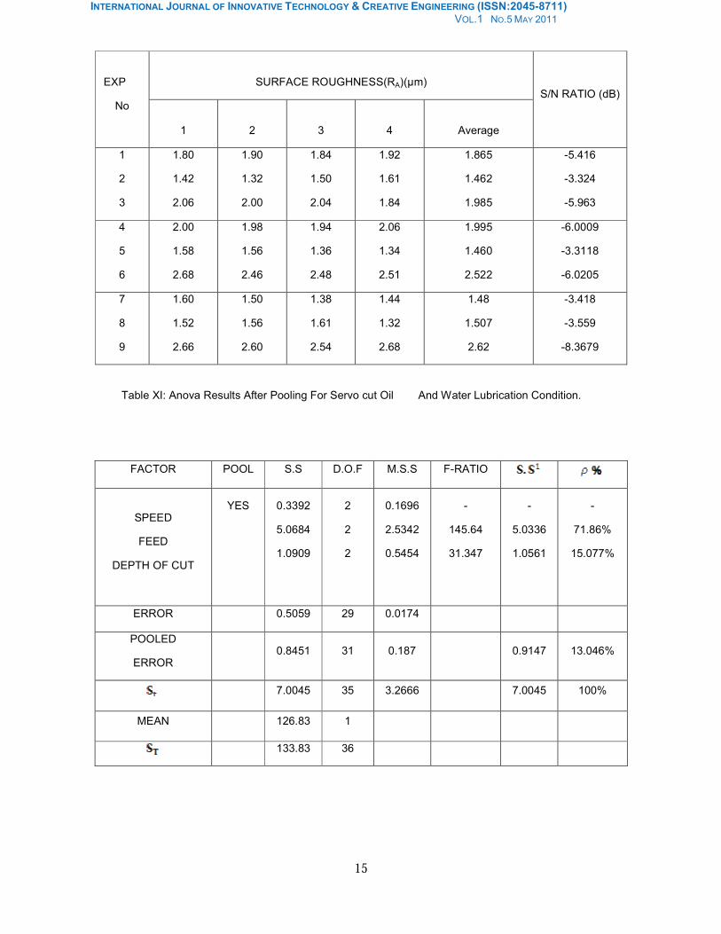
B. Flooded Machining (Servocut Oil + Water)
The experimentation is done similar to that of dry condition but with flooding of the cutting zone with a combination of servo cut oil and water. The results obtained are given in table 10 and
anova data is presented in table 11.
Table X: Data Summary Of Flooded Machining
(Servo cut Oil + Water) And S/N Ratio:
INTERNATIONAL JOURNAL OF INNOVATIVE TECHNOLOGY & CREATIVE ENGINEERING (ISSN:2045-8711) VOL.1 NO.5 MAY 2011
15
Table XI: Anova Results After Pooling For Servo cut Oil And Water Lubrication Condition.
FACTOR POOL S.S D.O.F M.S.S F-RATIO
SPEED
FEED
DEPTH OF CUT
YES 0.3392
5.0684
1.0909
2
2
2
0.1696
2.5342
0.5454
-
145.64
31.347
-
5.0336
1.0561
-
71.86%
15.077%
ERROR 0.5059 29 0.0174
POOLED
ERROR 0.8451 31 0.187 0.9147 13.046%
7.0045 35 3.2666 7.0045 100%
MEAN 126.83 1
133.83 36
SURFACE ROUGHNESS(RA)(µm) EXP
No
1 2 3 4 Average
S/N RATIO (dB)
1
2
3
1.80
1.42
2.06
1.90
1.32
2.00
1.84
1.50
2.04
1.92
1.61
1.84
1.865
1.462
1.985
-5.416
-3.324
-5.963
4
5
6
2.00
1.58
2.68
1.98
1.56
2.46
1.94
1.36
2.48
2.06
1.34
2.51
1.995
1.460
2.522
-6.0009
-3.3118
-6.0205
7
8
9
1.60
1.52
2.66
1.50
1.56
2.60
1.38
1.61
2.54
1.44
1.32
2.68
1.48
1.507
2.62
-3.418
-3.559
-8.3679
INTERNATIONAL JOURNAL OF INNOVATIVE TECHNOLOGY & CREATIVE ENGINEERING (ISSN:2045-8711) VOL.1 NO.5 MAY 2011
16
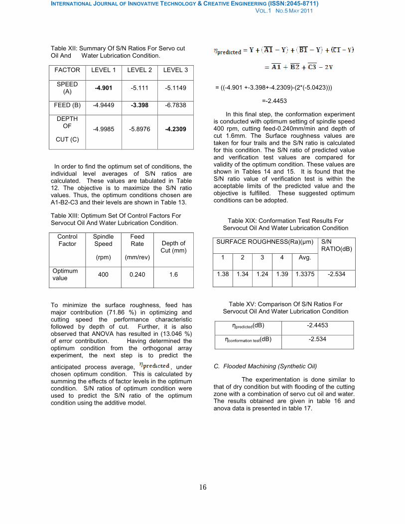
Table XII: Summary Of S/N Ratios For Servo cut Oil And Water Lubrication Condition.
FACTOR LEVEL 1 LEVEL 2 LEVEL 3
SPEED (A)
-4.901 -5.111 -5.1149
FEED (B) -4.9449 -3.398 -6.7838
DEPTH OF
CUT (C)
-4.9985 -5.8976 -4.2309
In order to find the optimum set of conditions, the individual level averages of S/N ratios are calculated. These values are tabulated in Table 12. The objective is to maximize the S/N ratio values. Thus, the optimum conditions chosen are A1-B2-C3 and their levels are shown in Table 13.
Table XIII: Optimum Set Of Control Factors For Servocut Oil And Water Lubrication Condition.
Control Factor
Spindle Speed
(rpm)
Feed Rate
(mm/rev)
Depth of Cut (mm)
Optimum value
400 0.240 1.6
To minimize the surface roughness, feed has major contribution (71.86 %) in optimizing and cutting speed the performance characteristic followed by depth of cut. Further, it is also observed that ANOVA has resulted in (13.046 %) of error contribution. Having determined the optimum condition from the orthogonal array experiment, the next step is to predict the
anticipated process average, , under chosen optimum condition. This is calculated by summing the effects of factor levels in the optimum condition. S/N ratios of optimum condition were used to predict the S/N ratio of the optimum condition using the additive model.
= ((-4.901 +-3.398+-4.2309)-(2*(-5.0423)))
=-2.4453
In this final step, the conformation experiment is conducted with optimum setting of spindle speed 400 rpm, cutting feed-0.240mm/min and depth of cut 1.6mm. The Surface roughness values are taken for four trails and the S/N ratio is calculated for this condition. The S/N ratio of predicted value and verification test values are compared for validity of the optimum condition. These values are shown in Tables 14 and 15. It is found that the S/N ratio value of verification test is within the acceptable limits of the predicted value and the objective is fulfilled. These suggested optimum conditions can be adopted.
Table XIX: Conformation Test Results For Servocut Oil And Water Lubrication Condition
SURFACE ROUGHNESS(Ra)(µm)
1 2 3 4 Avg.
S/N RATIO(dB)
1.38 1.34 1.24 1.39 1.3375 -2.534
Table XV: Comparison Of S/N Ratios For Servocut Oil And Water Lubrication Condition
ηpredicted(dB) -2.4453
ηconformation test(dB) -2.534
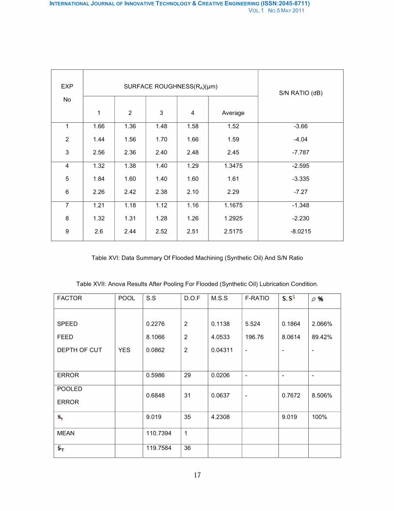
C. Flooded Machining (Synthetic Oil)
The experimentation is done similar to that of dry condition but with flooding of the cutting zone with a combination of servo cut oil and water. The results obtained are given in table 16 and
anova data is presented in table 17.
INTERNATIONAL JOURNAL OF INNOVATIVE TECHNOLOGY & CREATIVE ENGINEERING (ISSN:2045-8711) VOL.1 NO.5 MAY 2011
17
Table XVI: Data Summary Of Flooded Machining (Synthetic Oil) And S/N Ratio
Table XVII: Anova Results After Pooling For Flooded (Synthetic Oil) Lubrication Condition.
FACTOR POOL S.S D.O.F M.S.S F-RATIO
SPEED
FEED
DEPTH OF CUT YES
0.2276
8.1066
0.0862
2
2
2
0.1138
4.0533
0.04311
5.524
196.76
-
0.1864
8.0614
-
2.066%
89.42%
-
ERROR 0.5986 29 0.0206 - - -
POOLED
ERROR 0.6848 31 0.0637 - 0.7672 8.506%
9.019 35 4.2308 9.019 100%
MEAN 110.7394 1
119.7584 36
SURFACE ROUGHNESS(RA)(µm) EXP
No
1 2 3 4 Average
S/N RATIO (dB)
1
2
3
1.66
1.44
2.56
1.36
1.56
2.36
1.48
1.70
2.40
1.58
1.66
2.48
1.52
1.59
2.45
-3.66
-4.04
-7.787
4
5
6
1.32
1.84
2.26
1.38
1.60
2.42
1.40
1.40
2.38
1.29
1.60
2.10
1.3475
1.61
2.29
-2.595
-3.335
-7.27
7
8
9
1.21
1.32
2.6
1.18
1.31
2.44
1.12
1.28
2.52
1.16
1.26
2.51
1.1675
1.2925
2.5175
-1.348
-2.230
-8.0215
INTERNATIONAL JOURNAL OF INNOVATIVE TECHNOLOGY & CREATIVE ENGINEERING (ISSN:2045-8711) VOL.1 NO.5 MAY 2011
18
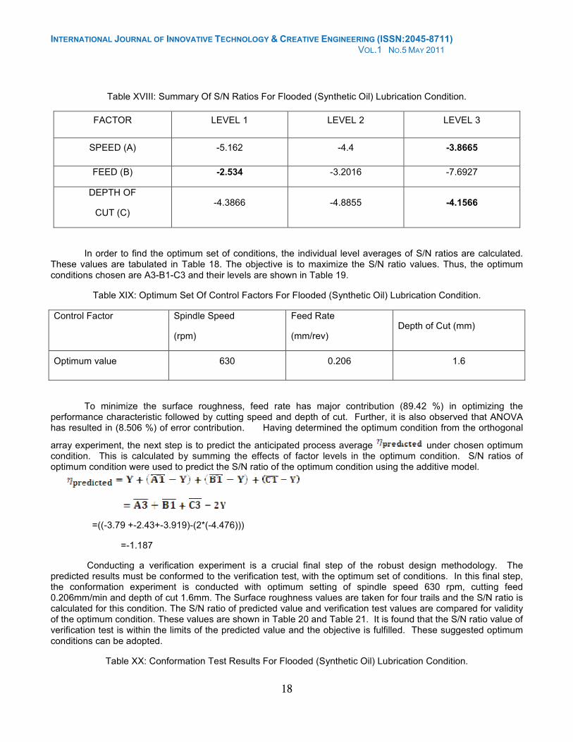
Table XVIII: Summary Of S/N Ratios For Flooded (Synthetic Oil) Lubrication Condition.
FACTOR LEVEL 1 LEVEL 2 LEVEL 3
SPEED (A) -5.162 -4.4 -3.8665
FEED (B) -2.534 -3.2016 -7.6927
DEPTH OF
CUT (C) -4.3866 -4.8855 -4.1566
In order to find the optimum set of conditions, the individual level averages of S/N ratios are calculated. These values are tabulated in Table 18. The objective is to maximize the S/N ratio values. Thus, the optimum conditions chosen are A3-B1-C3 and their levels are shown in Table 19.
Table XIX: Optimum Set Of Control Factors For Flooded (Synthetic Oil) Lubrication Condition.
Control Factor Spindle Speed
(rpm)
Feed Rate
(mm/rev) Depth of Cut (mm)
Optimum value 630 0.206 1.6
To minimize the surface roughness, feed rate has major contribution (89.42 %) in optimizing the performance characteristic followed by cutting speed and depth of cut. Further, it is also observed that ANOVA has resulted in (8.506 %) of error contribution. Having determined the optimum condition from the orthogonal
array experiment, the next step is to predict the anticipated process average under chosen optimum condition. This is calculated by summing the effects of factor levels in the optimum condition. S/N ratios of optimum condition were used to predict the S/N ratio of the optimum condition using the additive model.
=((-3.79 +-2.43+-3.919)-(2*(-4.476)))
=-1.187
Conducting a verification experiment is a crucial final step of the robust design methodology. The predicted results must be conformed to the verification test, with the optimum set of conditions. In this final step, the conformation experiment is conducted with optimum setting of spindle speed 630 rpm, cutting feed 0.206mm/min and depth of cut 1.6mm. The Surface roughness values are taken for four trails and the S/N ratio is calculated for this condition. The S/N ratio of predicted value and verification test values are compared for validity of the optimum condition. These values are shown in Table 20 and Table 21. It is found that the S/N ratio value of verification test is within the limits of the predicted value and the objective is fulfilled. These suggested optimum conditions can be adopted.
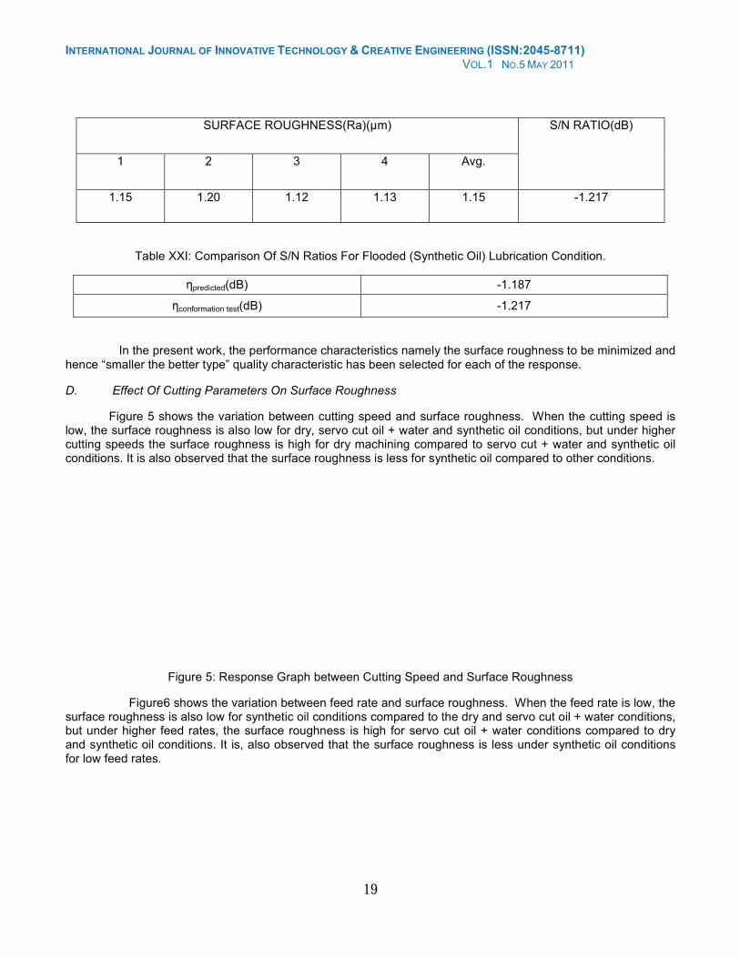
Table XX: Conformation Test Results For Flooded (Synthetic Oil) Lubrication Condition.
INTERNATIONAL JOURNAL OF INNOVATIVE TECHNOLOGY & CREATIVE ENGINEERING (ISSN:2045-8711) VOL.1 NO.5 MAY 2011
19
SURFACE ROUGHNESS(Ra)(µm)
1 2 3 4 Avg.
S/N RATIO(dB)
1.15 1.20 1.12 1.13 1.15 -1.217
Table XXI: Comparison Of S/N Ratios For Flooded (Synthetic Oil) Lubrication Condition.
ηpredicted(dB) -1.187
ηconformation test(dB) -1.217
In the present work, the performance characteristics namely the surface roughness to be minimized and hence “smaller the better type” quality characteristic has been selected for each of the response.
D. Effect Of Cutting Parameters On Surface Roughness
Figure 5 shows the variation between cutting speed and surface roughness. When the cutting speed is low, the surface roughness is also low for dry, servo cut oil + water and synthetic oil conditions, but under higher cutting speeds the surface roughness is high for dry machining compared to servo cut + water and synthetic oil conditions. It is also observed that the surface roughness is less for synthetic oil compared to other conditions.
Figure 5: Response Graph between Cutting Speed and Surface Roughness
Figure6 shows the variation between feed rate and surface roughness. When the feed rate is low, the surface roughness is also low for synthetic oil conditions compared to the dry and servo cut oil + water conditions, but under higher feed rates, the surface roughness is high for servo cut oil + water conditions compared to dry and synthetic oil conditions. It is, also observed that the surface roughness is less under synthetic oil conditions for low feed rates.
INTERNATIONAL JOURNAL OF INNOVATIVE TECHNOLOGY & CREATIVE ENGINEERING (ISSN:2045-8711) VOL.1 NO.5 MAY 2011
20
Figure 6: Response Graph between Feed Rate and Surface Roughness
Figure 7 shows the variation between depth of cut and surface roughness. When the depth of cut is low, the surface roughness is also low for synthetic oil conditions compared to the dry and servo cut oil + water conditions, but under higher depth of cut, the surface roughness is high for synthetic oil conditions compared to dry and servo cut oil + water conditions. It is observed that the surface roughness is less under synthetic oil conditions for low depth of cut.
Figure 7: Response Graph between Depth of Cut and Surface Roughness
E. Optimization Of Cutting Parameters
The optimum cutting parameters found in turning of Ti6Al4V alloy for low surface roughness and comparison of the optimum parameters for under Dry, Servo cut oil + water and Synthetic oil conditions are shown in the Table 22.
Table XXII: Optimum Parameters
Lubrication conditions SPEED
(A) (rpm) FEED RATE (B) (mm/min)
DEPTH OF CUT (C) (mm)
Dry 400 0.206 0.6
Servo cut oil+ water 400 0.240 1.6
Synthetic oil 630 0.206 1.6
From Table 22, it is observed that, the Synthetic oil is more effective at high cutting speed, high depth of cut and low feed rate compared to dry and servo cut oil + water conditions, whereas under servo cut oil + water condition is effective at higher depth of cut compared Dry and Synthetic oil. Dry machining suitable only at lower cutting speed, feed rate and depth of cut.
INTERNATIONAL JOURNAL OF INNOVATIVE TECHNOLOGY & CREATIVE ENGINEERING (ISSN:2045-8711) VOL.1 NO.5 MAY 2011
21
Feed rate has major contribution in optimizing the performance characteristics followed by depth of cut and cutting speed for dry and servo cut oil + water, whereas the feed rate has major contribution in optimizing the performance characteristics followed by cutting speed and depth of cut for Synthetic oil.
F. Influence Of Cooling Conditions:
The main primary purpose of the applying the coolants in machining are lubricating the cutting process primarily at low cutting speeds, cooling the work-piece primarily at high cutting speeds, flushing chips away from the cutting zone, improving tool life, reduced thermal deformation of workpiece and improving Surface Finish. In this project, different cooling conditions like dry, servo cut oil + water and synthetic oil has been chosen as the cutting fluids in machining of Ti-6Al-4V alloy. However in dry machining no coolant has been applied, hence in this machining no lubrication and cooling at machining zone appears. The servo cut oil + water has superior cooling and lubricating properties which impart excellent surface finish and minimizes tool wear. These are recommended for a variety of cutting operations on ferrous and non-ferrous metals; the kinematic viscosity of the servo cut oil varies in between 20 to 24 cst at 40°C. The synthet ic oils are water soluble synthetic coolants. The solutions prepared from these coolants are clear and free from any oil or fatty matter. These products have remarkable anti-rust characteristics. These oils recommended for machining of ferrous metals, high nickel and titanium alloys only. These oils are not recommended for machining of non-ferrous metals. The kinematic viscosity of the synthetic varies between 9 to 15 cst at 40° C.
As seen from the results of optimum process parameters for surface finish Table 5.1. The Synthetic oil is more effective at high cutting speed, high depth of cut and low feed rate compared to dry and servo cut oil + water conditions, the main reason for this is due to low viscosity of oil, high thermal conductivity compared to servo cut oil and these oils exhibits more cooling properties, but under servo cut oil + water condition is effective at higher depth of cut and moderate cutting speeds compared dry and synthetic oil, the main reason for this is due to high viscosity of oil, low thermal conductivity compared to synthetic oil and these oils exhibits more lubricating properties than cooling, where as dry machining suitable only at lower cutting speed, feed rate and
depth of cut because no cooling and lubrication action.
IV. CONCLUSIONS
Based on the results of the present experimental investigations on machining Ti6Al4V alloy, the following conclusions are drawn:
• The cutting performance on Ti6Al4V alloy with synthetic oil shows favorable and better performance compared to dry and servo cut oil + water.
• The synthetic oil as a cutting fluid in machining of Ti6Al4V alloy shows advantage in minimizing the surface roughness. ,
• The ANOVA shows that machining of Ti6Al4V alloy, the Synthetic oil is more effective at high cutting speed, high depth of cut and low feed rate compared to dry and servo cut oil + water conditions, but under servo cut oil + water condition is effective at higher depth of cut compared Dry and Synthetic oil, where as dry machining suitable only at lower cutting speed, feed rate and depth of cut.
• The ANOVA also reveals that feed rate is dominant parameter under dry, servo cut oil + water and synthetic oil conditions in optimizing the surface roughness.
REFERENCES
[1] Manna, A, Bhattacharyya, B., (May 2004), “Investigation for optimal parametric combination for achieving better surface finish during turning of Al/SiC-MMC”, The International Journal of Advanced Manufacturing Technology, Vol. 23, pp. 658-665(8)
[2] Heretis, Nektarios M.; Spanoudakis, Polychronis; Tsourveloudis, Nikos, (6 November 2009), “Surface roughness characteristics of Ti6Al4V alloy in conventional lathe and mill machining”, International Journal of Surface Science and Engineering, Vol. 3, pp. 435-447(13)
[3] Ram Cherukuri, Pal Molian, (2003), “Lathe Turning of Titanium Using Pulsed Laser Deposited, Ultra-Hard Boride Coatings of Carbide Inserts”, Machining Science and Technology: An International Journal, Vol. 7, pp. 119 – 135.
[4] S. K. Bhaumik , C. Divakar and A. K. Singh, (1995), “Machining Ti-6Al-4V alloy with a wBN-cBN composite tool”, Materials & Design, Vol. 16, pp. 221-226
[5] A.A.Ganeeva, A.A.Kruglov and R.Ya.Lutfullin, (2010), “Layered Material Manufactured From Titanium Alloy Ti-6al-4v”, Advanced Material Science Vol. 25, pp.136-141.


