Embed Size (px)
DESCRIPTION
IKD 1 is an I/O extension board
Citation preview

37135C
Manual Softwareversion 1.00xx
Manual 37135C
IKD 1 Digital I/O Expansion Board

Manual 37135C IKD 1 - Digital I/O Expansion Board
Page 2/41 © Woodward
WARNING Read this entire manual and all other publications pertaining to the work to be performed before instal-ling, operating, or servicing this equipment. Practice all plant and safety instructions and precautions. Failure to follow instructions can cause personal injury and/or property damage. The engine, turbine, or other type of prime mover should be equipped with an overspeed (overtempe-rature, or overpressure, where applicable) shutdown device(s), that operates totally independently of the prime mover control device(s) to protect against runaway or damage to the engine, turbine, or oth-er type of prime mover with possible personal injury or loss of life should the mechanical-hydraulic governor(s) or electric control(s), the actuator(s), fuel control(s), the driving mechanism(s), the lin-kage(s), or the controlled device(s) fail. Any unauthorized modifications to or use of this equipment outside its specified mechanical, electric-al, or other operating limits may cause personal injury and/or property damage, including damage to the equipment. Any such unauthorized modifications: (i) constitute "misuse" and/or "negligence" with-in the meaning of the product warranty thereby excluding warranty coverage for any resulting damage, and (ii) invalidate product certifications or listings.
CAUTION To prevent damage to a control system that uses an alternator or battery-charging device, make sure the charging device is turned off before disconnecting the battery from the system. Electronic controls contain static-sensitive parts. Observe the following precautions to prevent dam-age to these parts. • Discharge body static before handling the control (with power to the control turned off, contact a
grounded surface and maintain contact while handling the control). • Avoid all plastic, vinyl, and Styrofoam (except antistatic versions) around printed circuit boards. • Do not touch the components or conductors on a printed circuit board with your hands or with
conductive devices.
OUT-OF-DATE PUBLICATION This publication may have been revised or updated since this copy was produced. To verify that you have the latest revision, be sure to check the Woodward website: http://www.woodward.com/pubs/current.pdf The revision level is shown at the bottom of the front cover after the publication number. The latest version of most publications is available at: http://www.woodward.com/publications If your publication is not there, please contact your customer service representative to get the latest copy.
Important definitions
WARNING Indicates a potentially hazardous situation that, if not avoided, could result in death or serious injury.
CAUTION Indicates a potentially hazardous situation that, if not avoided, could result in damage to equipment.
NOTE Provides other helpful information that does not fall under the warning or caution categories.
Woodward reserves the right to update any portion of this publication at any time. Information provided by Woodward is believed to be correct and reliable. However, Woodward assumes no responsibility unless otherwise expressly undertaken.
© Woodward
All Rights Reserved.
Manual 37135C IKD 1 - Digital I/O Expansion Board
© Woodward Page 3/41
Revision History
Rev. Date Editor Changes NEW 03-02-14 Tr Release A 04-06-03 TP Minor corrections B 07-12-20 TP Minor corrections C 11-09-08 TE Minor corrections
Contents
CHAPTER 1. GENERAL INFORMATION ........................................................................................ 5 Introduction ................................................................................................................................................ 5
CHAPTER 2. ELECTROSTATIC DISCHARGE AWARENESS ............................................................. 6
CHAPTER 3. INSTALLATION ....................................................................................................... 7 Power Supply ............................................................................................................................................ 7 Discrete Inputs .......................................................................................................................................... 8
Positive Logic .................................................................................................................................. 8 Negative Logic ................................................................................................................................ 8
Relay Outputs ............................................................................................................................................ 9 Interface .................................................................................................................................................. 10
CAN Bus ....................................................................................................................................... 10 DPC - Direct Configuration Cable ................................................................................................. 12
CHAPTER 4. FUNCTIONAL DESCRIPTION .................................................................................. 13 Introduction .............................................................................................................................................. 13 Main Functions ........................................................................................................................................ 14
Coupling to a Higher Level Control Unit (e.g. GCP) ...................................................................... 14 Coupling to a PLC ......................................................................................................................... 14
CAN Bus Telegrams ............................................................................................................................... 15 Discrete Inputs ........................................................................................................................................ 18 Relay Outputs .......................................................................................................................................... 18 Configuration Options .............................................................................................................................. 18
CHAPTER 5. LEDS AND INTERFACES....................................................................................... 19 LEDs ........................................................................................................................................................ 19 Interfaces................................................................................................................................................. 19 Direct Configuration (DPC)...................................................................................................................... 19
CHAPTER 6. CONFIGURATION.................................................................................................. 20 Basic Data ............................................................................................................................................... 20 CAN Bus Parameter ................................................................................................................................ 21 Discrete Inputs ........................................................................................................................................ 24 Relay Outputs .......................................................................................................................................... 27
CHAPTER 7. COMMISSIONING .................................................................................................. 29
APPENDIX A. WIRING DIAGRAM ............................................................................................... 30
APPENDIX B. DIMENSIONS ...................................................................................................... 31
APPENDIX C. TECHNICAL DATA ............................................................................................... 32
Manual 37135C IKD 1 - Digital I/O Expansion Board
Page 4/41 © Woodward
APPENDIX D. LIST OF PARAMETERS ........................................................................................ 33
APPENDIX E. SERVICE OPTIONS .............................................................................................. 36 Product Service Options ......................................................................................................................... 36 Returning Equipment For Repair ............................................................................................................ 36
Packing A Control ......................................................................................................................... 37 Return Authorization Number RAN .............................................................................................. 37
Replacement Parts ................................................................................................................................. 37 How To Contact Woodward .................................................................................................................... 38 Engineering Services .............................................................................................................................. 39 Technical Assistance .............................................................................................................................. 40
Illustrations
Figure 3-1: Power supply ............................................................................................................................................................. 7 Figure 3-2: Discrete inputs - positive logic .................................................................................................................................. 8 Figure 3-3: Discrete input - negative logic .................................................................................................................................. 8 Figure 3-4: Relay outputs ............................................................................................................................................................ 9 Figure 3-5: Interface - Terminals ............................................................................................................................................... 10 Figure 3-6: Interface - loop of CAN bus .................................................................................................................................... 10 Figure 3-7: Interface - shielding of CAN bus ............................................................................................................................ 11 Figure 6-1: NO/NC .................................................................................................................................................................... 27 Figure 7-1: Wiring diagram ....................................................................................................................................................... 30 Figure 7-2: Dimensions ............................................................................................................................................................. 31

Manual 37135C IKD 1 - Digital I/O Expansion Board
© Woodward Page 5/41
Chapter 1. General Information
Introduction ≡≡≡≡≡≡≡≡≡≡≡≡≡≡≡≡≡≡≡≡≡≡≡≡≡
The IKD 1 is an external digital expansion card that can be used alternatively with an upper level control unit (e. g. GCP) or an PLC. The IKD 1 can read the status of 8 discrete inputs and transmit these via the CAN bus to the higher level control unit. In the opposite direction the higher level control unit can control the 8 relay outputs situated on the IKD 1 via the CAN bus. Type designation of the IKD 1 as follows: IKD1 M
Mounting
[S]..Vibration absorber [M]..DIN-rail/rear panel mounting
Model Examples: • IKD1M (standard unit for DIN-rail/rear panel mounting) • IKD1S (standard unit for vibration absorber mounting) Intended Use The item must only be operated for the uses described in this manual. The prerequisite for a proper and safe operation of the product is correct transportation, storage, and installation as well as careful operation and maintenance.
NOTE These manual have been developed for an item fitted with all available options. Inputs/outputs, func-tions, configuration screens and other details described, which do not exist on your item may be ig-nored. The present manual has been prepared to enable the installation and commissioning of the item. On account of the large variety of parameter settings, it is not possible to cover every possible combina-tion. The manual are therefore only a guide. In case of incorrect entries or a total loss of functions, the default settings can be taken from the enclosed list of parameters.

Manual 37135C IKD 1 - Digital I/O Expansion Board
Page 6/41 © Woodward
Chapter 2. Electrostatic Discharge Awareness
All electronic equipment is static-sensitive, some components more than others. To protect these components from static damage, you must take special precautions to minimize or eliminate electrostatic discharges. Follow these precautions when working with or near the control. 1. Before doing maintenance on the electronic control, discharge the static electricity on your body to ground by
touching and holding a grounded metal object (pipes, cabinets, equipment, etc.). 2. Avoid the build-up of static electricity on your body by not wearing clothing made of synthetic materials.
Wear cotton or cotton-blend materials as much as possible because these do not store static electric charges as much as synthetics.
3. Keep plastic, vinyl, and Styrofoam materials (such as plastic or Styrofoam cups, cup holders, cigarette pack-
ages, cellophane wrappers, vinyl books or folders, plastic bottles, and plastic ash trays) away from the con-trol, the modules, and the work area as much as possible.
4. Do not remove the printed circuit board (PCB) from the control cabinet unless absolutely necessary. If you
must remove the PCB from the control cabinet, follow these precautions:
• Ensure that the device is completely de-energized (all connectors must be disconnected).
• Do not touch any part of the PCB except the edges.
• Do not touch the electrical conductors, the connectors, or the components with conductive devices or with your hands.
• When replacing a PCB, keep the new PCB in the plastic antistatic protective bag it comes in until you
are ready to install it. Immediately after removing the old PCB from the control cabinet, place it in the antistatic protective bag.
Warning To prevent damage to electronic components caused by improper handling, read and observe the pre-cautions in Woodward manual 82715, Guide for Handling and Protection of Electronic Controls, Printed Circuit Boards, and Modules.
Manual 37135C IKD 1 - Digital I/O Expansion Board
© Woodward Page 7/41
Chapter 3. Installation
Caution A circuit breaker must be provided near to the device and in a position easily accessible to the opera-tor. This must also bear a sign identifying it as an isolating switch for the unit.
NOTE Inductivities connected (such as coils of operating current or undervoltage tripping devices, or aux-iliary or power contacts) must be connected to a suitable interference suppressor.
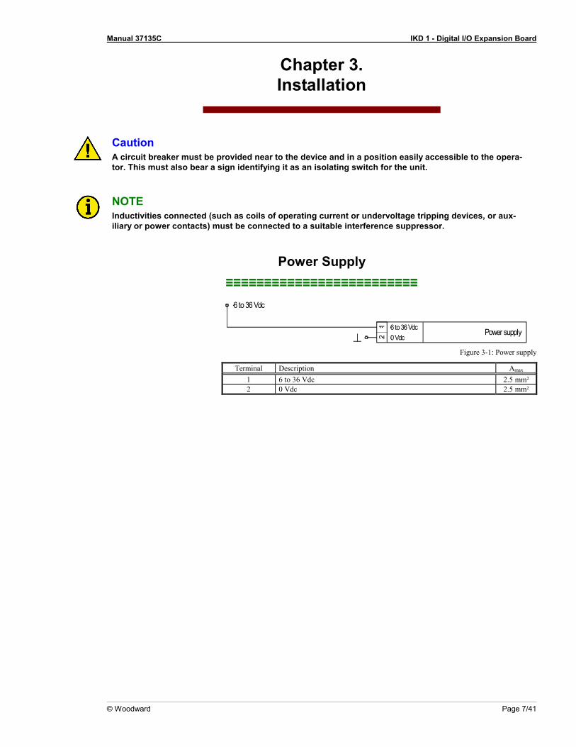
Power Supply ≡≡≡≡≡≡≡≡≡≡≡≡≡≡≡≡≡≡≡≡≡≡≡≡≡
Power supply
6 to 36 Vdc
12 0 Vdc
6 to 36 Vdc
Figure 3-1: Power supply
Terminal Description Amax 1 6 to 36 Vdc 2.5 mm² 2 0 Vdc 2.5 mm²
Manual 37135C IKD 1 - Digital I/O Expansion Board
Page 8/41 © Woodward
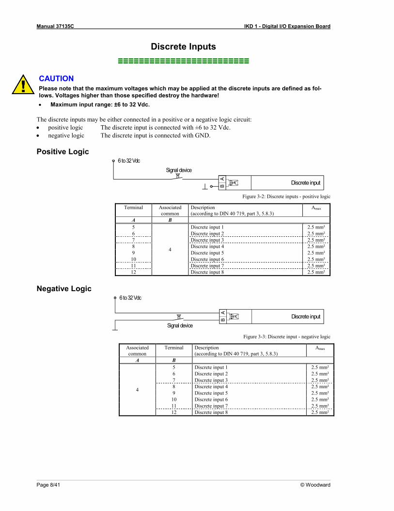
Discrete Inputs ≡≡≡≡≡≡≡≡≡≡≡≡≡≡≡≡≡≡≡≡≡≡≡≡≡
CAUTION Please note that the maximum voltages which may be applied at the discrete inputs are defined as fol-lows. Voltages higher than those specified destroy the hardware! • Maximum input range: ±6 to 32 Vdc.
The discrete inputs may be either connected in a positive or a negative logic circuit: • positive logic The discrete input is connected with ±6 to 32 Vdc. • negative logic The discrete input is connected with GND.
Positive Logic 6 to 32 Vdc
Signal device
Discrete input
AB
Figure 3-2: Discrete inputs - positive logic
Terminal Associated common
Description (according to DIN 40 719, part 3, 5.8.3)
Amax
A B 5
4
Discrete input 1 2.5 mm² 6 Discrete input 2 2.5 mm² 7 Discrete input 3 2.5 mm² 8 Discrete input 4 2.5 mm² 9 Discrete input 5 2.5 mm²
10 Discrete input 6 2.5 mm² 11 Discrete input 7 2.5 mm² 12 Discrete input 8 2.5 mm²
Negative Logic
Discrete input
AB
Signal device
6 to 32 Vdc
Figure 3-3: Discrete input - negative logic
Associated common
Terminal Description (according to DIN 40 719, part 3, 5.8.3)
Amax
A B
4
5 Discrete input 1 2.5 mm² 6 Discrete input 2 2.5 mm² 7 Discrete input 3 2.5 mm² 8 Discrete input 4 2.5 mm² 9 Discrete input 5 2.5 mm²
10 Discrete input 6 2.5 mm² 11 Discrete input 7 2.5 mm² 12 Discrete input 8 2.5 mm²
Manual 37135C IKD 1 - Digital I/O Expansion Board
© Woodward Page 9/41
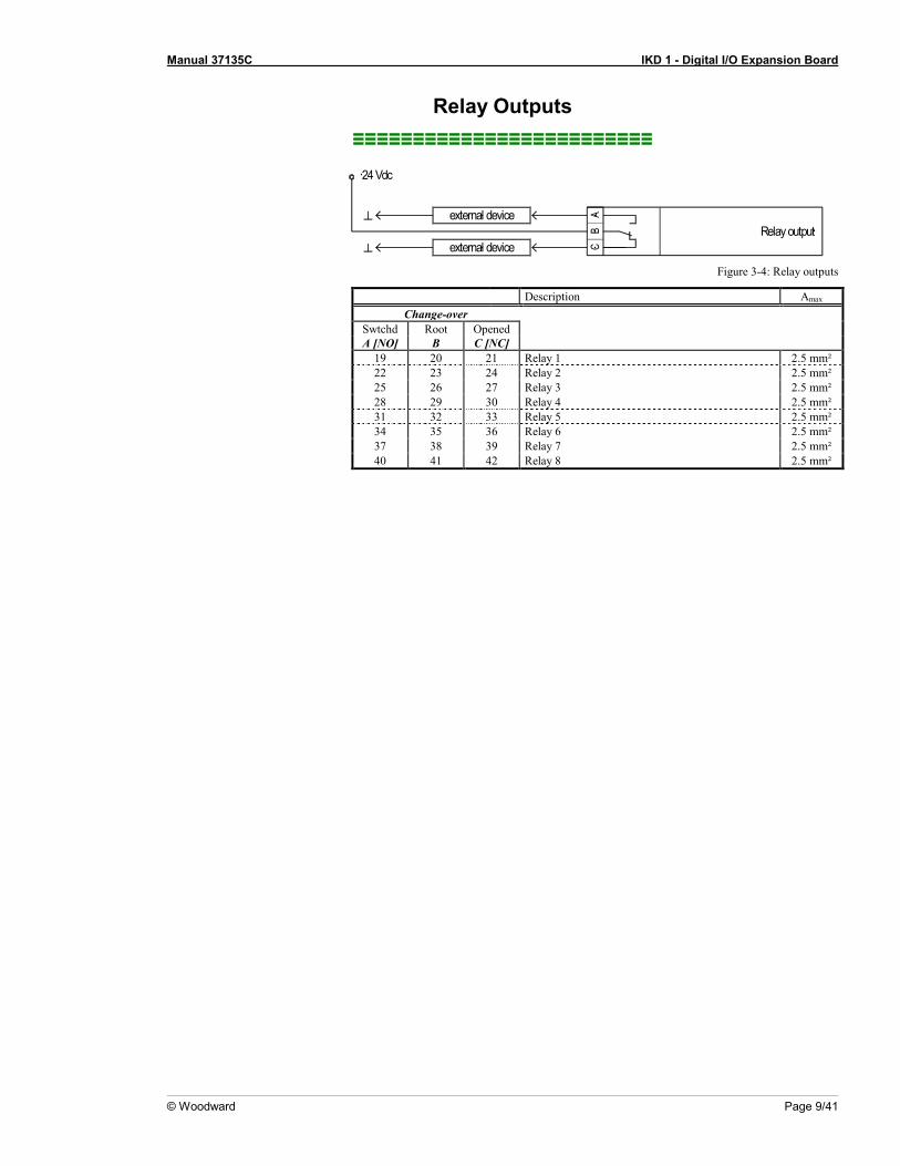
Relay Outputs ≡≡≡≡≡≡≡≡≡≡≡≡≡≡≡≡≡≡≡≡≡≡≡≡≡
Relay outputexternal device
external device
AB
C
24 Vdc
Figure 3-4: Relay outputs
Description Amax Change-over
Swtchd Root Opened A [NO] B C [NC]
19 20 21 Relay 1 2.5 mm² 22 23 24 Relay 2 2.5 mm² 25 26 27 Relay 3 2.5 mm² 28 29 30 Relay 4 2.5 mm² 31 32 33 Relay 5 2.5 mm² 34 35 36 Relay 6 2.5 mm² 37 38 39 Relay 7 2.5 mm² 40 41 42 Relay 8 2.5 mm²
Manual 37135C IKD 1 - Digital I/O Expansion Board
Page 10/41 © Woodward
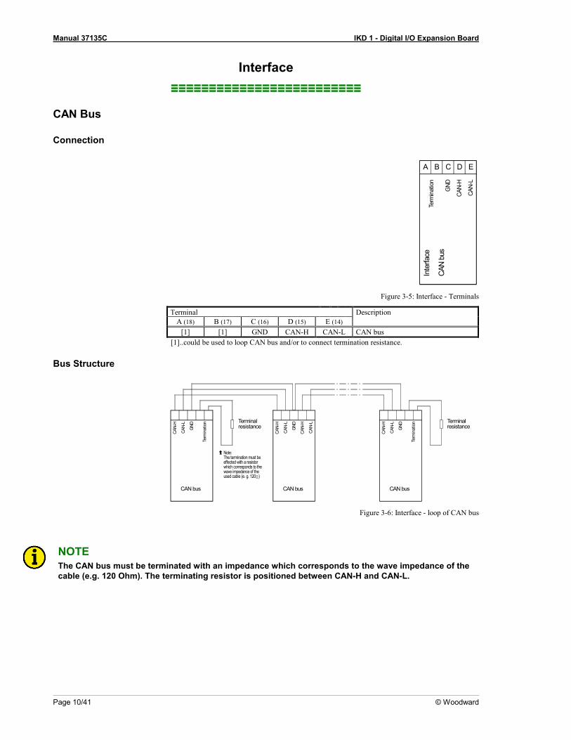
Interface ≡≡≡≡≡≡≡≡≡≡≡≡≡≡≡≡≡≡≡≡≡≡≡≡≡
CAN Bus
Connection
Inte
rface
CAN
bus
CAN-
L
Term
inat
ion
CAN-
H
GND
CA B D E
Figure 3-5: Interface - Terminals
Terminal Description A (18) B (17) C (16) D (15) E (14)
[1] [1] GND CAN-H CAN-L CAN bus [1]..could be used to loop CAN bus and/or to connect termination resistance.
Bus Structure
Terminalresistance
Note:The termination must beeffected with a resistorwhich corresponds to thewave impedance of theused cable (e. g. 120 )
CAN bus
CAN-
H
CAN-
L
GND
Term
inat
ion
Ω
CAN bus
CAN-
HTerminalresistance
CAN-
L
CAN-
H
CAN-
L
GND
CAN-
L
CAN-
H
CAN bus
Term
inat
ion
GND
Figure 3-6: Interface - loop of CAN bus
NOTE The CAN bus must be terminated with an impedance which corresponds to the wave impedance of the cable (e.g. 120 Ohm). The terminating resistor is positioned between CAN-H and CAN-L.
Manual 37135C IKD 1 - Digital I/O Expansion Board
© Woodward Page 11/41
Possible CAN Bus Problems
If no data is transmitted on the CAN bus, check the following for common CAN bus communication problems: • T structure bus is utilized • CAN-L and CAN-H are interchanged • Not all devices on the bus are using identical Baud rates • Terminating resistor are missing • Baud rate to high for wiring length • The CAN bus cable is co-routed with power cables
Woodward recommends the use of twisted-pair cables for the CAN bus (i.e.: Lappkabel Unitronic LIYCY (TP) 2×2×0.25, UNITRONIC-Bus LD 2×2×0.22).
Maximum CAN bus Length
The maximum length of the communication bus wiring is dependent on the configured Baud rate. Refer to the fol-lowing table for the maximum bus length (Source: CANopen; Holger Zeltwanger (Hrsg.); 2001 VDE VERLAG GMBH, Berlin und Offenbach; ISBN 3-8007-2448-0).
Baud rate Max. length 1000 kbit/s 25 m 800 kbit/s 50 m 500 kbit/s 100 m 125 kbit/s 250 m 50 kbit/s 1000 m 20 kbit/s 2500 m
The maximum specified length for the communication bus wiring might not be achieved if poor quality wire is utilized, there is high contact resistance, or other conditions exist. Reducing the baud rate may overcome these is-sues.
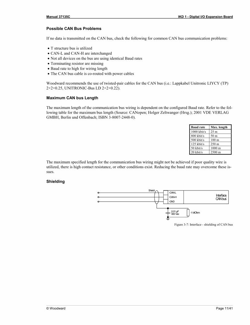
Shielding
InterfaceCAN bus
CAN-L
CAN-H
GND
Shield
1 MOhm0.01 µF400 Vac
Figure 3-7: Interface - shielding of CAN bus

Manual 37135C IKD 1 - Digital I/O Expansion Board
Page 12/41 © Woodward
DPC - Direct Configuration Cable The IKD 1 provides a configuration interface for connecting a computer via the DPC (direct configuration cable). The configuration interface is the RJ45 socket on the IKD 1 board.
NOTE Configuration with the direct configuration cable DPC (P/N 5417-557) is possible. A laptop/PC, the DPC cable, the program LeoPC1 version 3.1.1 or higher (included on CD Rom with control unit), and the proper configuration files are required.
NOTE The connection cable delivered with the DPC must be used between DPC and IKD 1 to ensure proper functionality of the IKD 1. An extension or utilization of different cable types for the connection be-tween IKD 1 and DPC may result a malfunction of the IKD 1. This may possibly result in damage to components of the system. If an extension of the data connection line is required, only the serial cable (RS-232) between DPC and laptop/PC may be extended. It is recommended to use an industry standard cable for this.

Manual 37135C IKD 1 - Digital I/O Expansion Board
© Woodward Page 13/41
Chapter 4. Functional Description
Introduction ≡≡≡≡≡≡≡≡≡≡≡≡≡≡≡≡≡≡≡≡≡≡≡≡≡
The IKD 1 is a external expansion board with totally • 8 discrete inputs as well as • 8 relay outputs. This in- and outputs can be alternatively controlled from • a higher level control unit (e.g. GCP, easYgen) or • a PLC. Therefore different parameters are available that have to be adjusted in dependence of the application. The IKD 1 is to be used dependent on the definition alternatively at • the Engine CAN bus (coupling via a higher level control unit, e.g. GCP) or directly at • the Guidance CAN bus (coupling to a PLC). Following main functions apply dependent on the use.

Manual 37135C IKD 1 - Digital I/O Expansion Board
Page 14/41 © Woodward
Main Functions ≡≡≡≡≡≡≡≡≡≡≡≡≡≡≡≡≡≡≡≡≡≡≡≡≡
Coupling to a Higher Level Control Unit (e.g. GCP) 1. Recognition of status transferred via external sensors to the discrete inputs and transfer via the engine
CAN bus to the higher level control unit that is coupled with the IKD 1. Evaluation is proceeded according to the configured action and additional steps are initiated.
2. Output of signals to the relays that are received from the higher level control unit. For this feature it is possible to configure the relays of the IKD 1 using the relay manager of the higer level control unit (please note external description of higher level control unit).
Coupling to a PLC 1. Recognition of status transferred via external sensors to the discrete inputs and transfer via the engine
CAN bus to the PLC that is coupled with the IKD 1. Evaluation is proceeded according to the program in the PLC.
2. Output of signals to the relays that are received from the PLC. For this feature the relays have to be con-trolled from the PLC

Manual 37135C IKD 1 - Digital I/O Expansion Board
© Woodward Page 15/41
CAN Bus Telegrams ≡≡≡≡≡≡≡≡≡≡≡≡≡≡≡≡≡≡≡≡≡≡≡≡≡
Communication via the CAN bus is used to exchange data between components coupled to the CAN bus. Using the CAN bus it is possible to cyclically output internal data. If configuration is proceeded using the D-1 parame-ters are equal to the parameters of the full version of LeoPC1 (please note that the CAN IDs can only be read-out).
Identifier (ID)
The IDs can be configured. Please note that selected CAN bus specific parameters can only be changed using the direct configuration interface (e.g. baud rate and IDs).
NOTE When setting the ID please make sure that no conflicts occur with other bus participants.
NOTE If you configure a Node ID ≠ 0 no other IDs have to be configured. All other IDs are automatically pre-assigned and configuration as well as display of IDs is invalid thereby. The displayed IDs during confi-guration are valid for Node ID = 0 !
6 transmit or receive message boxes are scheduled which IDs can be freely assigned at Node ID = 0: • receiving of data, • transmitting of data, • receiving of configuration messages, • transmitting of an answer to a configuration message, • receiving of uploads and • sending of uploads. Additionally the unit reacts on start/stop messages on ID 0.
Manual 37135C IKD 1 - Digital I/O Expansion Board
Page 16/41 © Woodward
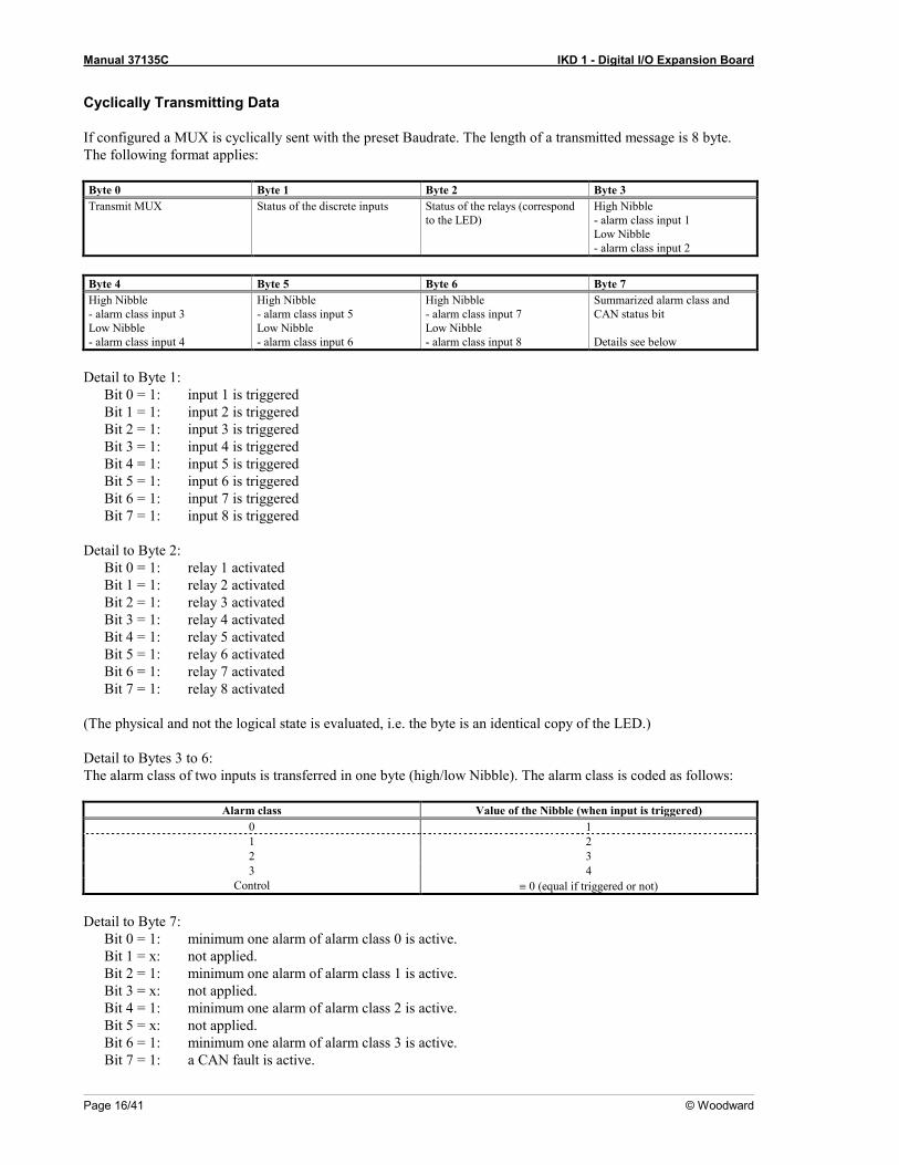
Cyclically Transmitting Data
If configured a MUX is cyclically sent with the preset Baudrate. The length of a transmitted message is 8 byte. The following format applies: Byte 0 Byte 1 Byte 2 Byte 3 Transmit MUX Status of the discrete inputs Status of the relays (correspond
to the LED) High Nibble - alarm class input 1 Low Nibble - alarm class input 2
Byte 4 Byte 5 Byte 6 Byte 7 High Nibble - alarm class input 3 Low Nibble - alarm class input 4
High Nibble - alarm class input 5 Low Nibble - alarm class input 6
High Nibble - alarm class input 7 Low Nibble - alarm class input 8
Summarized alarm class and CAN status bit Details see below
Detail to Byte 1:
Bit 0 = 1: input 1 is triggered Bit 1 = 1: input 2 is triggered Bit 2 = 1: input 3 is triggered Bit 3 = 1: input 4 is triggered Bit 4 = 1: input 5 is triggered Bit 5 = 1: input 6 is triggered Bit 6 = 1: input 7 is triggered Bit 7 = 1: input 8 is triggered
Detail to Byte 2:
Bit 0 = 1: relay 1 activated Bit 1 = 1: relay 2 activated Bit 2 = 1: relay 3 activated Bit 3 = 1: relay 4 activated Bit 4 = 1: relay 5 activated Bit 5 = 1: relay 6 activated Bit 6 = 1: relay 7 activated Bit 7 = 1: relay 8 activated
(The physical and not the logical state is evaluated, i.e. the byte is an identical copy of the LED.) Detail to Bytes 3 to 6: The alarm class of two inputs is transferred in one byte (high/low Nibble). The alarm class is coded as follows:
Alarm class Value of the Nibble (when input is triggered) 0 1 1 2 2 3 3 4
Control ≡ 0 (equal if triggered or not) Detail to Byte 7:
Bit 0 = 1: minimum one alarm of alarm class 0 is active. Bit 1 = x: not applied. Bit 2 = 1: minimum one alarm of alarm class 1 is active. Bit 3 = x: not applied. Bit 4 = 1: minimum one alarm of alarm class 2 is active. Bit 5 = x: not applied. Bit 6 = 1: minimum one alarm of alarm class 3 is active. Bit 7 = 1: a CAN fault is active.

Manual 37135C IKD 1 - Digital I/O Expansion Board
© Woodward Page 17/41
Receiving Data
The length of a received message is 8 byte. The following format applies: Byte 0 Byte 1 Byte 2 Byte 3 Receiving MUX Desired relay status Acknowledgment, ignore relay
demand, enable Details see below
Not applied
Byte 4 Byte 5 Byte 6 Byte 7 Not applied Not applied Not applied Not applied
Detail to Byte 1:
Bit 0 = 1: set relay 1 Bit 1 = 1: set relay 2 Bit 2 = 1: set relay 3 Bit 3 = 1: set relay 4 Bit 4 = 1: set relay 5 Bit 5 = 1: set relay 6 Bit 6 = 1: set relay 7 Bit 7 = 1: set relay 8
Detail to Byte 2:
Bit 0 = 1: Acknowledgment (applies only at a change from 0 to 1 and only if the message has been enabled for minimum two cycles.)
Bit 1 = 1 The content of Byte 1 (desired relay status) is ignored at this message. The relays remain in their previous status.
Bit 2 = 1 Enable evaluation of the digital inputs (see configuration.) Bit 3 to 7 ≡ 0
Start/Stop of Cyclically Transmission of Data Via CAN Bus
Bus The ID for a start/stop message is always 0. The length of the message is 2 Bytes.
Byte 0 "1" for start, "2" for stop. Byte 1 Node ID or "0" (common command for all units on the bus).
NOTE Using configuration different start behaviors can be selected.
Manual 37135C IKD 1 - Digital I/O Expansion Board
Page 18/41 © Woodward
Discrete Inputs ≡≡≡≡≡≡≡≡≡≡≡≡≡≡≡≡≡≡≡≡≡≡≡≡≡
For each discrete input the following parameters can be configured separately: • type of action (NO/NC), • alarm class (control input, class 0, 1, 2 or 3), • tripping delay, • release delay, • enable conditions, • type of resetting, and • is the input used as a remote acknowledgment input.
Relay Outputs ≡≡≡≡≡≡≡≡≡≡≡≡≡≡≡≡≡≡≡≡≡≡≡≡≡
For each relay output the following parameters can be configured separately: • type of action (NO/NC), • base status (during CAN bus failure), • is the relay 1 used as a readiness for operation relay (using this setting no other function can be assigned to
the relay) and • is a CAN bus failure is recorded via a relay. (Note: If you want to record time-critical alarms via a relay
please use the relays directly contained in the higher level control unit to eliminate delays caused by CAN run-times.)
Configuration Options ≡≡≡≡≡≡≡≡≡≡≡≡≡≡≡≡≡≡≡≡≡≡≡≡≡
The following options exist for configuration. Configuration can be done alternatively via • the configuration plug using the direct configuration cable DPC and the PC program LeoPC1 • the CAN bus using the D-1 unit
Manual 37135C IKD 1 - Digital I/O Expansion Board
© Woodward Page 19/41
Chapter 5. LEDs And Interfaces
LEDs ≡≡≡≡≡≡≡≡≡≡≡≡≡≡≡≡≡≡≡≡≡≡≡≡≡
The LEDs on the PCB are used to display the status of the unit.
LED A "Readiness for operation"
Color: GREEN
This LED indicates that power supply has been applied.
LED B
"CAN bus" Color: YELLOW
Is the CAN bus active this LED is flashing.
LED C
"Alarm" Color: RED
This LED indicates an alarm. Is a discrete input triggered and is at least alarm class 1 configured to the input the LED is shining.
LED input 1 to 8 Color: YELLOW
This LED indicates the physical status of the inputs. Is a input set to a high level this LED is shining.
Interfaces ≡≡≡≡≡≡≡≡≡≡≡≡≡≡≡≡≡≡≡≡≡≡≡≡≡
The IKD 1 is equipped with two interfaces working with the following baud rates: • Direct configuration 1,200 Baud (8 Bit, no parity, 1 Stop bit) and • CAN bus (CiA) 125, 250 or 500 kBaud configurable using the serial interface.
Direct Configuration (DPC) ≡≡≡≡≡≡≡≡≡≡≡≡≡≡≡≡≡≡≡≡≡≡≡≡≡
Using the configuration interface the unit can be configured directly. Therefore a direct configuration cable DPC is necessary that is connected on one side with the PC/laptop and on the other side at the unit. For the direct configuration a file is necessary that can be opened using the PC program LeoPC1 (file name: xxxx-xxxx-yyy-zz.asm, whereas 'xxxx-xxxx' is the product number, 'yyy' the revision number and 'zz' the language [US = English, DE = German]). The parameters described in chapter "Configuration" beginning page 20 could be modified with this file.
Manual 37135C IKD 1 - Digital I/O Expansion Board
Page 20/41 © Woodward
Chapter 6. Configuration
Configuration can be carried out using a PC and the PC program LeoPC1^1 via the serial interface. Additionally configuration can be carried out via the CAN bus. The following baud rates apply: • Configuration via direct configuration = 1,200 Baud and • CAN bus configuration: The baud rate corresponds to the baud rate for transmitting and receiving messages.
It can be configured using the direct configuration (125, 250, 500 kBaud according CiA).
CAUTION Do not change parameters during operation.
The parameters can be changed using the PC program LeoPC1 (see separate manual).
NOTE Please note the list of parameters at the end of this manual.
Basic Data ≡≡≡≡≡≡≡≡≡≡≡≡≡≡≡≡≡≡≡≡≡≡≡≡≡
Software version Software version
Version number of the software.
Software number Software number for identification
Unique identification number.
Manual 37135C IKD 1 - Digital I/O Expansion Board
© Woodward Page 21/41
CAN Bus Parameter ≡≡≡≡≡≡≡≡≡≡≡≡≡≡≡≡≡≡≡≡≡≡≡≡≡
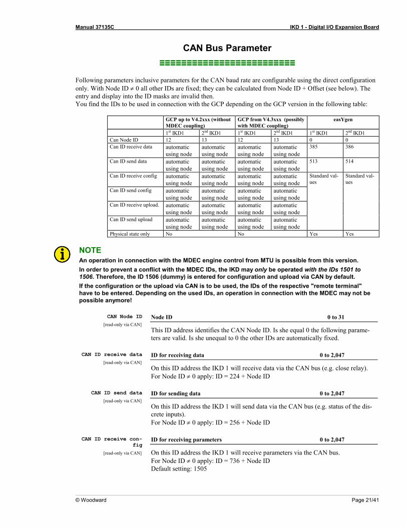
Following parameters inclusive parameters for the CAN baud rate are configurable using the direct configuration only. With Node ID ≠ 0 all other IDs are fixed; they can be calculated from Node ID + Offset (see below). The entry and display into the ID masks are invalid then. You find the IDs to be used in connection with the GCP depending on the GCP version in the following table:
GCP up to V4.2xxx (without MDEC coupling)
GCP from V4.3xxx (possibly with MDEC coupling)
easYgen
1st IKD1 2nd IKD1 1st IKD1 2nd IKD1 1st IKD1 2nd IKD1 Can Node ID 12 13 12 13 0 0 Can ID receive data automatic
using node automatic using node
automatic using node
automatic using node
385 386
Can ID send data automatic using node
automatic using node
automatic using node
automatic using node
513 514
Can ID receive config automatic using node
automatic using node
automatic using node
automatic using node
Standard val-ues
Standard val-ues
Can ID send config automatic using node
automatic using node
automatic using node
automatic using node
Can ID receive upload. automatic using node
automatic using node
automatic using node
automatic using node
Can ID send upload automatic using node
automatic using node
automatic using node
automatic using node
Physical state only No No Yes Yes
NOTE An operation in connection with the MDEC engine control from MTU is possible from this version. In order to prevent a conflict with the MDEC IDs, the IKD may only be operated with the IDs 1501 to 1506. Therefore, the ID 1506 (dummy) is entered for configuration and upload via CAN by default. If the configuration or the upload via CAN is to be used, the IDs of the respective "remote terminal" have to be entered. Depending on the used IDs, an operation in connection with the MDEC may not be possible anymore!
CAN Node ID
[read-only via CAN] Node ID 0 to 31
This ID address identifies the CAN Node ID. Is she equal 0 the following parame-ters are valid. Is she unequal to 0 the other IDs are automatically fixed.
CAN ID receive data
[read-only via CAN] ID for receiving data 0 to 2,047
On this ID address the IKD 1 will receive data via the CAN bus (e.g. close relay). For Node ID ≠ 0 apply: ID = 224 + Node ID
CAN ID send data
[read-only via CAN] ID for sending data 0 to 2,047
On this ID address the IKD 1 will send data via the CAN bus (e.g. status of the dis-crete inputs). For Node ID ≠ 0 apply: ID = 256 + Node ID
CAN ID receive con-
fig
[read-only via CAN]
ID for receiving parameters 0 to 2,047
On this ID address the IKD 1 will receive parameters via the CAN bus. For Node ID ≠ 0 apply: ID = 736 + Node ID Default setting: 1505

Manual 37135C IKD 1 - Digital I/O Expansion Board
Page 22/41 © Woodward
CAN ID send config
[read-only via CAN] ID for sending parameters 0 to 2,047
On this ID address the IKD 1 will send parameters via the CAN bus. For Node ID ≠ 0 apply: ID = 768 + Node ID Default setting: 1505
CAN ID receive upl-
oad
[read-only via CAN]
ID for receiving parameters from a higher level control 0 to 2,047
On this ID address the IKD 1 will receive parameters from a higher level control unit via the CAN bus. For Node ID ≠ 0 apply: ID = 800 + Node ID Default setting: 1505
CAN ID send upload
[read-only via CAN] ID for sending of visualization masks 0 to 2,047
On this ID the IKD 1 will send visualization masks to the higher level control unit via the CAN bus. For Node ID ≠ 0 apply: ID = 832 + Node ID Default setting: 1505
CAN baudrate
[read-only via CAN] Baudrate 125/250/500 kBaud
With this baud rate the CAN communication will be driven. Note: If the IKD 1 is working with a GCP please enter 250 kBaud here. Default setting: 250 kBaud Note: If the IKD 1 is operated together with an MDEC, 125 kBaud have to be set here.
Mux send MUX for sending of data 0 to 255
With the MUX different sending messages can be distinguished on the same Identifi-er. Default setting: 1
Mux receive MUX for receiving of data 0 to 255
With the MUX different receiving messages can be distinguished on the same Iden-tifier. Default setting: 1
Rate to send (s) Rate of sending 0 to 99.98s
The sending rate can be adjusted here. If you set "0" the unit does not send anything. Default setting: 0.10s Note (see below): To enable the unit to send messages either the following parameter has to be set to S/S Off or S/S+AUT or a start command has to be received via the CAN bus.
Manual 37135C IKD 1 - Digital I/O Expansion Board
© Woodward Page 23/41
Start-up procedure Handling during start-up S/S Off / S/S+Aut / S/S-Aut
This parameter sets the handling during start-up (cyclical sending of data via the CAN bus). See also Start/Stop of Cyclically Transmission of Data Via CAN Bus on page 17. S/S Off ......... no start/stop (for operation with GCP)
With switching-on the unit it sends with the configured sending baud rate data via the CAN bus. Interruption of sending is not possible.
S/S+Aut ....... Start/stop with auto start With switching-on the unit it sends with the configured sending baud rate data via the CAN bus. Interruption and re-start of sending is poss-ible via the CAN bus.
S/S-Aut ........ Start/stop without auto start Sending of data is started after this has been enabled through a CAN bus signal. Sending can be interrupted and re-start as often as neces-sary via the CAN bus.
Default setting: no start/stop Note: • To enable the unit to send data a sending baud rate (≥ 20 ms) has to be confi-
gured (see above)! • Auto start is enabled one second after applying the power supply. • Start/stop commands would accepted one second after receiving of the message,
too. If you configure via the CAN bus (D-1): 0.................... no start/stop 1.................... start/stop with auto start 2.................... start/stop without auto start
CAN error delay (s) Triggering time for CAN faults (timeout) 0 to -99.98 s
If you configure "0" in this screen an CAN fault would not lead to an alarm. If the unit did not receive data within this configured limit a CAN fault is recognized. If a relay has been configured (see further below) this would be triggered. The status of the rest of the relays would not be changed or the relays would be set to base setting (depends on configuration). Additionally in Byte 7 of the CAN sending message a fault bit is set. If the CAN still allows this message can be received by another CAN participant. Note: It is not allowed to lower this time under the sending baud rate of the corresponding unit.
CAN error
self-acknowledgment CAN alarm acknowledgment YES/NO
Here you can configure the type of acknowledgment for CAN alarms. YES .............. self acknowledgment
The alarm message is canceled right after the CAN fault has been cleared.
NO ................ no self acknowledgment The alarm message is canceled right after the CAN fault has been cleared and a acknowledgment has been received.
Note: Acknowledgment can be done via the CAN bus or the configured discrete input (if configured).
Manual 37135C IKD 1 - Digital I/O Expansion Board
Page 24/41 © Woodward
Discrete Inputs ≡≡≡≡≡≡≡≡≡≡≡≡≡≡≡≡≡≡≡≡≡≡≡≡≡
Phys. state
[ Physical state only YES/NO
Attention! This parameter affects all inputs! NO ................ Only the logical state of the inputs is forwarded to the CAN. (The set-
tings under function NC, tripping delay, enable delay, remote enabling, self acknowledgement and remote acknowledgement are active). This setting has to be selected when operating in connection with GCP.
YES .............. Only the physical state of the inputs is forwarded to the CAN. (The set-tings under function NC, tripping delay, enable delay, remote enabling, self acknowledgement and remote acknowledgement have no effect.) This setting has to be selected for devices, which include this parame-ters already e.g. easYgen.
Default setting: No
Function NC
[x = 1 to 8] Type YES/NO
The discrete inputs can be triggered via a NO or NC input. A NC input allows to monitor a wire break. A positive or negative voltage difference can be applied. NO ................ NO input
The discrete input triggers if voltage is applied. YES .............. NC input
The discrete input triggers if no voltage is applied.
Tripping delay (s)
[x = 1 to 8] Triggering delay 0.00 to 99.98 s
The triggering of a discrete input can be delayed by an individual time. If you enter "0" the delay is smaller than 20 ms. To trigger the alarm the input has to be applied for at least the time set here. If the voltage isn't applied during the whole period the delay is re-started. Note: This delay is related to internal calculation times of the IKD 1. The time until a unit coupled to the CAN bus reacts additionally depends on the runtime of the message through the CAN bus. Therefore time critical messages should always been wired di-rectly to the control unit GCP.
Enable delay (s)
[x = 1 to 8] Reset delay 0.00 to 99.98 s
The reset of a discrete input can be delayed by an individual time. If you enter "0" the delay is smaller than 20 ms. To reset the alarm the input has not to be applied for at least the time set here. If the voltage is applied during the reset delay the delay is re-started. Note: Triggering of the input can be reset after this time.

Manual 37135C IKD 1 - Digital I/O Expansion Board
© Woodward Page 25/41
Remote enabling
[x = 1 to 8] Enable YES/NO
Evaluation of the discrete inputs can be configured as depended on a enable signal (e.g. at the GCP the delayed engine monitoring). Therefore the enable Bit (Byte 2, Bit 2) in the receiving message is prepared. NO ................ Evaluation is done independent of the enable Bit. YES .............. Evaluation is done following the enable Bit has been set via the CAN
bus (triggering time starts with setting the enable Bit and the discrete input).
Note: The enable Bit does not affect the 8 status LEDs; they always indicate the physical status of the discrete inputs.
Alarm class
[x = 1 to 8] Alarm class / modus Control / 0 / 1 / 2 / 3
Every discrete input can be configured with an alarm class (control 0, 1, 2, 3). If one input with alarm class ≥ 1 has been triggered the alarm LED (LED "C") lights up. Note: Control input should be configured to self acknowledgment. Applying a control in-put does not trigger an alarm class. Using configuration via CAN bus (e. g. with the D-1) the alarm class can not be set directly. A modus (0..4) has to be entered that refers to the corresponding alarm class (see table below). Modus Alarm class 0 Control 1 0 2 1 3 2 4 3
Self acknowledgment
[x = 1 to 8] Self acknowledgement YES/NO
Type acknowledgment for every input can be set here. NO ................ no self acknowledgment (for operation with GCP)
Triggering is delayed after the input signal has be reset for the time of the reset delay and if a acknowledge signal has been set.
YES .............. self-acknowledgment Triggering is delayed after the input signal has been reset for the time of the reset delay.
Note: Setting YES has to be chosen for control inputs.

Manual 37135C IKD 1 - Digital I/O Expansion Board
Page 26/41 © Woodward
Remote acknowledg
[x = 1 to 8] Select input for acknowledgment YES/NO
Any of the discrete inputs can be set as the acknowledgment input. If a acknowledg-ment input is set all triggering are reset if the input signal is reset for at least the con-figured reset delay of each input. If a triggering delay is configured for the acknowl-edgment input this time has to be over until a acknowledgment is accepted. NO ................ The input is no acknowledgment input. (for operation with GCP) YES .............. The input is an acknowledgment input. Note: If an input is configured as an acknowledgment input he also should be configured to self acknowledgment and alarm class "control input".
Manual 37135C IKD 1 - Digital I/O Expansion Board
© Woodward Page 27/41
Relay Outputs ≡≡≡≡≡≡≡≡≡≡≡≡≡≡≡≡≡≡≡≡≡≡≡≡≡
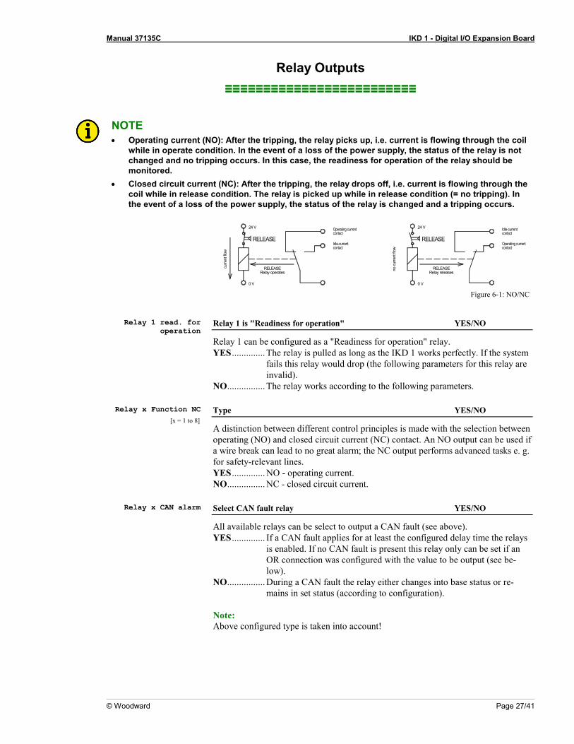
NOTE • Operating current (NO): After the tripping, the relay picks up, i.e. current is flowing through the coil
while in operate condition. In the event of a loss of the power supply, the status of the relay is not changed and no tripping occurs. In this case, the readiness for operation of the relay should be monitored.
• Closed circuit current (NC): After the tripping, the relay drops off, i.e. current is flowing through the coil while in release condition. The relay is picked up while in release condition (= no tripping). In the event of a loss of the power supply, the status of the relay is changed and a tripping occurs.
Operating currentcontact
Idle-currentcontact
curre
nt fl
ow
0 V
RELEASERelay operates
24 V
RELEASE
Operating currentcontact
Idle-currentcontact
RELEASERelay releasesno
cur
rent
flow
0 V
RELEASE
24 V
Figure 6-1: NO/NC
Relay 1 read. for
operation Relay 1 is "Readiness for operation" YES/NO
Relay 1 can be configured as a "Readiness for operation" relay. YES .............. The relay is pulled as long as the IKD 1 works perfectly. If the system
fails this relay would drop (the following parameters for this relay are invalid).
NO ................ The relay works according to the following parameters. Relay x Function NC
[x = 1 to 8] Type YES/NO
A distinction between different control principles is made with the selection between operating (NO) and closed circuit current (NC) contact. An NO output can be used if a wire break can lead to no great alarm; the NC output performs advanced tasks e. g. for safety-relevant lines. YES .............. NO - operating current. NO ................ NC - closed circuit current.
Relay x CAN alarm Select CAN fault relay YES/NO
All available relays can be select to output a CAN fault (see above). YES .............. If a CAN fault applies for at least the configured delay time the relays
is enabled. If no CAN fault is present this relay only can be set if an OR connection was configured with the value to be output (see be-low).
NO ................ During a CAN fault the relay either changes into base status or re-mains in set status (according to configuration).
Note: Above configured type is taken into account!
Manual 37135C IKD 1 - Digital I/O Expansion Board
Page 28/41 © Woodward
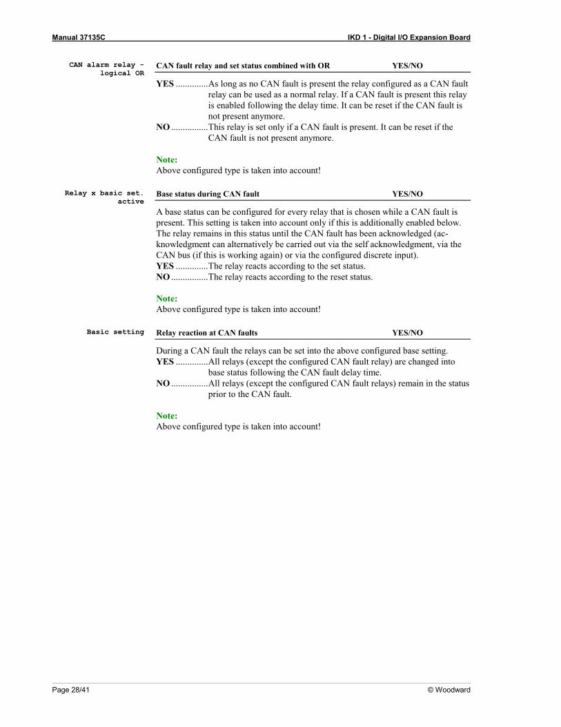
CAN alarm relay -
logical OR CAN fault relay and set status combined with OR YES/NO
YES .............. As long as no CAN fault is present the relay configured as a CAN fault relay can be used as a normal relay. If a CAN fault is present this relay is enabled following the delay time. It can be reset if the CAN fault is not present anymore.
NO ................ This relay is set only if a CAN fault is present. It can be reset if the CAN fault is not present anymore.
Note: Above configured type is taken into account!
Relay x basic set.
active Base status during CAN fault YES/NO
A base status can be configured for every relay that is chosen while a CAN fault is present. This setting is taken into account only if this is additionally enabled below. The relay remains in this status until the CAN fault has been acknowledged (ac-knowledgment can alternatively be carried out via the self acknowledgment, via the CAN bus (if this is working again) or via the configured discrete input). YES .............. The relay reacts according to the set status. NO ................ The relay reacts according to the reset status. Note: Above configured type is taken into account!
Basic setting Relay reaction at CAN faults YES/NO
During a CAN fault the relays can be set into the above configured base setting. YES .............. All relays (except the configured CAN fault relay) are changed into
base status following the CAN fault delay time. NO ................ All relays (except the configured CAN fault relays) remain in the status
prior to the CAN fault. Note: Above configured type is taken into account!

Manual 37135C IKD 1 - Digital I/O Expansion Board
© Woodward Page 29/41
Chapter 7. Commissioning
DANGER - HIGH VOLTAGE When commissioning the unit, please observe the five safety rules applying to the handling of live equipment. Make sure that you know how to provide first aid in current-related accidents and that you know where the first-aid kit and the nearest telephone are. Never touch any live components of the sys-tem or on the back of the system:
D A N G E R T O L I V E
CAUTION Only a qualified technician may commission unit. The "EMERGENCY-OFF" function must be safely working prior to the commissioning, and must not depend on the unit.
Step-by-step instruction 1. Following check-out if all inputs, outputs, and the CAN bus have been wired correct power supply can be ap-
plied. 2. If a configuration/change of pre-specified values should be necessary please follow the instructions for confi-
guration in chapter "Configuration" at page 20. 3. Parameters of the higher level control unit have to be adjusted. Therefore please note the manual of the used
control.

Manual 37135C IKD 1 - Digital I/O Expansion Board
Page 30/41 © Woodward
Appendix A. Wiring Diagram
Relay 1
5
0 V DC
2002-11-07 | IKD 1 Wiring Diagram ikd1ww-4502-ap.skf
4
6
7
8
4241
40
12
45
67
89
1011
12
NO
NC
12/24 V DCSubject to technical mocifications.
Common
Digital input 1
Digital input 2
Digital input 3
Digital input 4
Digital input 5
Digital input 6
Digital input 7
Digital input 8
The socket for the PC configurationis situated on the top of the unit.
This is where the DPChas to be plugged in.
IKD
1 (D
igita
le I/
O E
xten
sion
Boar
d)
3
2
1
CAN bus
14CAN-L
CAN-H 15
GND 16
CAN-L 17
CAN-H 18
Relay 2
3938
37
Relay 3
3635
34
Relay 4
3332
31
Relay 5
3029
28
Relay 6
2726
25
Relay 7
2423
22
Relay 8
2120
19
NO
NC
NO
NC
NO
NC
NO
NC
NO
NC
NO
NC
NO
NC
133
N/C
0 V DC
Figure 7-1: Wiring diagram

Manual 37135C IKD 1 - Digital I/O Expansion Board
© Woodward Page 31/41
Appendix B. Dimensions
Dire
ctco
nfigu
ratio
nco
nnec
tor
309
128 mm
8
6
12345
7
2021
2526272829
222324
19
18
1011121314151617
24 mm
168
mm
Subje
ct to
techn
ical m
odific
ation
s.
Note
:An
insta
llatio
n in
the
engin
e sw
itch
box i
s not
reco
mm
ende
d if t
he u
nitis
faste
ned
via sn
ap-o
n ra
ilins
talla
tion.
For
this,
a vi
brat
ionab
sorb
er h
as to
be
used
.
2003
-01-08
| IK
D 1 D
imen
sions
ikd1
ww-02
03-ab
.skf
Mou
nting
ove
r the
pcb
12 mm 101 mm
122 mm
152
mm
141
mm
42
3233
3738394041
343536
31
39 mm
51 mm
Figure 7-2: Dimensions

Manual 37135C IKD 1 - Digital I/O Expansion Board
Page 32/41 © Woodward
Appendix C. Technical Data
Ambient variables ---------------------------------------------------------------------------------------------- - Power supply (Vaux) ---------------------------------------------------- 12/24 Vdc (6.0 to 36.0 Vdc) - Intrinsic consumption ------------------------------------------------------------------------- max. 3 W - Ambient temperature for storage ------------- -40 to 85 °C / -40 to 185 °F (P/N: 8440-2028) - Ambient temperature for storage ------------- -30 to 80 °C / -22 to 176 °F (P/N: 8440-1041) - Ambient temperature for operation ----------------------------------- -20 to 70 °C / -4 to 158 °F - Ambient humidity -------------------------------------------------------------- 95 %, not condensing
Discrete inputs ------------------------------------------------------------------------ galvanically isolated - Input range (VCont., dig.input) -------------------------------- Rated voltage 12/24 Vdc (6 to 32 Vdc) - Input resistance ------------------------------------------------------------------------- approx. 6.8 kΩ
Relay outputs ---------------------------------------------------------------------------------- potential free - Contact material --------------------------------------------------------------------------------- AgCdO - General purpose (GP) (VCont, relay output)
AC ------------------------------------ 2.00 Aac@250 Vac DC -------------------------------------- 2.00 Adc@24 Vdc ------------------------------------ 0.36 Adc@125 Vdc ------------------------------------ 0.18 Adc@250 Vdc
- Pilot duty (PD) (VCont, relay output) AC ------------------------------------------------------ B300 DC -------------------------------------- 1.00 Adc@24 Vdc ------------------------------------ 0.22 Adc@125 Vdc
------------------------------------ 0.10 Adc@250 Vdc
Interface, Service interface ----------------------------------------------------------------------------------- - Version -------------------------------------------------------------------------------------------- RS-232 - Signal level -------------------------------------------------------------------------------------------- 5 V
---------------------------------- Level conversion and insulation by using DPC (P/N 5417-557)
Interface, CAN ----------------------------------------------------------------------- galvanically isolated - Insulation voltage (continuously) ------------------------------------------------------------ 100 Vdc - Insulation test voltage (≤ 5 s) --------------------------------------------------------------- 1,000 Vac - Version ------------------------------------------------------------------------------------------ CAN-Bus - Internal line termination ------------------------------------------------------------------ not available
Housing ---------------------------------------------------------------------------------------------------------- - Extrusion profile for fastening onto a DIN rail/C profile ------------------------------- Um 122 - Dimensions ------------------------------------------------------------------------ 168 × 128 × 51 mm - Vibration absorber ------------------------------------------------------------------------------ M4×6 - Dimensions ------------------------------------------------------------------------ 152 × 122 × 52 mm - Wiring ------------------------------------------------------------------Screw-plug terminals 2.5 mm²
------------------------------------------------------------------ Recommended locked torque 0.5 Nm -------------------------------------------------------------------------- use 60/75 °C copper wire only --------------------------------------------------------------------- use class 1 wire only or equivalent
- Weight-------------------------------------------------------------------------------------- approx. 360 g
Protection -------------------------------------------------------------------------------------------------------- - Protection type -------------------------------------------------------------------------------------- IP 00 - EMC test (CE) -------------------------------------- tested according to applicable EN guidelines - Type approval ............... UL/cUL, Ordinary Locations, File No.: 231544 (P/N: 8440-2028)
Manual 37135C IKD 1 - Digital I/O Expansion Board
© Woodward Page 33/41
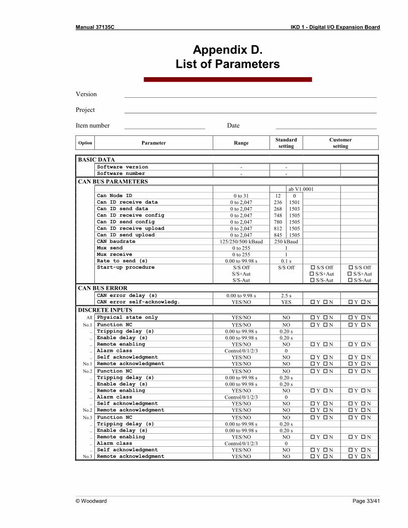
Appendix D. List of Parameters
Version ___________________________________________________________________________ Project ___________________________________________________________________________ Item number ________________________ Date ______________________________
Option Parameter Range Standard setting
Customer setting
BASIC DATA Software version - - Software number - -
CAN BUS PARAMETERS ab V1.0001 Can Node ID 0 to 31 12 0 Can ID receive data 0 to 2,047 236 1501 Can ID send data 0 to 2,047 268 1503 Can ID receive config 0 to 2,047 748 1505 Can ID send config 0 to 2,047 780 1505 Can ID receive upload 0 to 2,047 812 1505 Can ID send upload 0 to 2,047 845 1505 CAN baudrate 125/250/500 kBaud 250 kBaud Mux send 0 to 255 1 Mux receive 0 to 255 1 Rate to send (s) 0.00 to 99.98 s 0.1 s Start-up procedure S/S Off
S/S+Aut S/S-Aut
S/S Off S/S Off S/S+Aut S/S-Aut
S/S Off S/S+Aut S/S-Aut
CAN BUS ERROR CAN error delay (s) 0.00 to 9.98 s 2.5 s CAN error self-acknowledg. YES/NO YES Y N Y N
DISCRETE INPUTS All Physical state only YES/NO NO Y N Y N
No.1 Function NC YES/NO NO Y N Y N .. Tripping delay (s) 0.00 to 99.98 s 0.20 s .. Enable delay (s) 0.00 to 99.98 s 0.20 s .. Remote enabling YES/NO NO Y N Y N .. Alarm class Control/0/1/2/3 0 .. Self acknowledgment YES/NO NO Y N Y N
No.1 Remote acknowledgment YES/NO NO Y N Y N No.2 Function NC YES/NO NO Y N Y N
.. Tripping delay (s) 0.00 to 99.98 s 0.20 s
.. Enable delay (s) 0.00 to 99.98 s 0.20 s
.. Remote enabling YES/NO NO Y N Y N
.. Alarm class Control/0/1/2/3 0
.. Self acknowledgment YES/NO NO Y N Y N No.2 Remote acknowledgment YES/NO NO Y N Y N No.3 Function NC YES/NO NO Y N Y N
.. Tripping delay (s) 0.00 to 99.98 s 0.20 s
.. Enable delay (s) 0.00 to 99.98 s 0.20 s
.. Remote enabling YES/NO NO Y N Y N
.. Alarm class Control/0/1/2/3 0
.. Self acknowledgment YES/NO NO Y N Y N No.3 Remote acknowledgment YES/NO NO Y N Y N
Manual 37135C IKD 1 - Digital I/O Expansion Board
Page 34/41 © Woodward
Option Parameter Range Standard setting
Customer setting
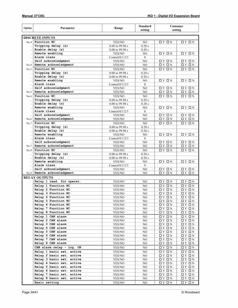
DISCRETE INPUTS No.4 Function NC YES/NO NO Y N Y N
.. Tripping delay (s) 0.00 to 99.98 s 0.20 s
.. Enable delay (s) 0.00 to 99.98 s 0.20 s
.. Remote enabling YES/NO NO Y N Y N
.. Alarm class Control/0/1/2/3 0
.. Self acknowledgment YES/NO NO Y N Y N No.4 Remote acknowledgment YES/NO NO Y N Y N No.5 Function NC YES/NO NO Y N Y N
.. Tripping delay (s) 0.00 to 99.98 s 0.20 s
.. Enable delay (s) 0.00 to 99.98 s 0.20 s
.. Remote enabling YES/NO NO Y N Y N
.. Alarm class Control/0/1/2/3 0
.. Self acknowledgment YES/NO NO Y N Y N No.5 Remote acknowledgment YES/NO NO Y N Y N No.6 Function NC YES/NO NO Y N Y N
.. Tripping delay (s) 0.00 to 99.98 s 0.20 s
.. Enable delay (s) 0.00 to 99.98 s 0.20 s
.. Remote enabling YES/NO NO Y N Y N
.. Alarm class Control/0/1/2/3 0
.. Self acknowledgment YES/NO NO Y N Y N No.6 Remote acknowledgment YES/NO NO Y N Y N No.7 Function NC YES/NO NO Y N Y N
.. Tripping delay (s) 0.00 to 99.98 s 0.20 s
.. Enable delay (s) 0.00 to 99.98 s 0.20 s
.. Remote enabling YES/NO NO Y N Y N
.. Alarm class Control/0/1/2/3 0
.. Self acknowledgment YES/NO NO Y N Y N No.7 Remote acknowledgment YES/NO NO Y N Y N No.8 Function NC YES/NO NO Y N Y N
.. Tripping delay (s) 0.00 to 99.98 s 0.20 s
.. Enable delay (s) 0.00 to 99.98 s 0.20 s
.. Remote enabling YES/NO NO Y N Y N
.. Alarm class Control/0/1/2/3 0
.. Self acknowledgment YES/NO NO Y N Y N No.8 Remote acknowledgment YES/NO NO Y N Y N
RELAY OUTPUTS Relay 1 read. for operat. YES/NO NO Y N Y N Relay 1 Function NC YES/NO NO Y N Y N Relay 2 Function NC YES/NO NO Y N Y N Relay 3 Function NC YES/NO NO Y N Y N Relay 4 Function NC YES/NO NO Y N Y N Relay 5 Function NC YES/NO NO Y N Y N Relay 6 Function NC YES/NO NO Y N Y N Relay 7 Function NC YES/NO NO Y N Y N Relay 8 Function NC YES/NO NO Y N Y N Relay 1 CAN alarm YES/NO NO Y N Y N Relay 2 CAN alarm YES/NO NO Y N Y N Relay 3 CAN alarm YES/NO NO Y N Y N Relay 4 CAN alarm YES/NO NO Y N Y N Relay 5 CAN alarm YES/NO NO Y N Y N Relay 6 CAN alarm YES/NO NO Y N Y N Relay 7 CAN alarm YES/NO NO Y N Y N Relay 8 CAN alarm YES/NO NO Y N Y N CAN alarm relay - log. OR YES/NO NO Y N Y N Relay 1 basic set. active YES/NO NO Y N Y N Relay 2 basic set. active YES/NO NO Y N Y N Relay 3 basic set. active YES/NO NO Y N Y N Relay 4 basic set. active YES/NO NO Y N Y N Relay 5 basic set. active YES/NO NO Y N Y N Relay 6 basic set. active YES/NO NO Y N Y N Relay 7 basic set. active YES/NO NO Y N Y N Relay 8 basic set. active YES/NO NO Y N Y N Basic setting YES/NO NO Y N Y N

Manual 37135C IKD 1 - Digital I/O Expansion Board
© Woodward Page 35/41

Manual 37135C IKD 1 - Digital I/O Expansion Board
Page 36/41 © Woodward
Appendix E. Service Options
Product Service Options ≡≡≡≡≡≡≡≡≡≡≡≡≡≡≡≡≡≡≡≡≡≡≡≡≡
The following factory options are available for servicing Woodward equipment, based on the standard Woodward Product and Service Warranty (5-01-1205) that is in effect at the time the product is purchased from Woodward or the service is performed. If you are experiencing problems with installation or unsatisfactory performance of an installed system, the following options are available: • • Consult the troubleshooting guide in the manual. • • Contact Woodward technical assistance (see "How to Contact Woodward" later in this chapter) and dis-
cuss your problem. In most cases, your problem can be resolved over the phone. If not, you can select which course of action you wish to pursue based on the available services listed in this section.
Returning Equipment For Repair ≡≡≡≡≡≡≡≡≡≡≡≡≡≡≡≡≡≡≡≡≡≡≡≡≡
If a control (or any part of an electronic control) is to be returned to Woodward for repair, please contact Wood-ward in advance to obtain a Return Authorization Number. When shipping the unit(s), attach a tag with the fol-lowing information: • • name and location where the control is installed; • • name and phone number of contact person; • • complete Woodward part numbers (P/N) and serial number (S/N); • • description of the problem; • • instructions describing the desired type of repair.
CAUTION To prevent damage to electronic components caused by improper handling, read and observe the pre-cautions in Woodward manual 82715, Guide for Handling and Protection of Electronic Controls, Printed Circuit Boards, and Modules.

Manual 37135C IKD 1 - Digital I/O Expansion Board
© Woodward Page 37/41
Packing A Control Use the following materials when returning a complete control: • • protective caps on any connectors; • • antistatic protective bags on all electronic modules; • • packing materials that will not damage the surface of the unit; • • at least 100 mm (4 inches) of tightly packed, industry-approved packing material; • • a packing carton with double walls; • • a strong tape around the outside of the carton for increased strength.
Return Authorization Number RAN When returning equipment to Woodward, please telephone and ask for the Customer Service Department in Stuttgart [+49 (0) 711 789 54-0]. They will help expedite the processing of your order through our distributors or local service facility. To expedite the repair process, contact Woodward in advance to obtain a Return Authoriza-tion Number, and arrange for issue of a purchase order for the unit(s) to be repaired. No work can be started until a purchase order is received.
NOTE We highly recommend that you make arrangement in advance for return shipments. Contact a Wood-ward customer service representative at +49 (0) 711 789 54-0 for instructions and for a Return Authori-zation Number.
Replacement Parts ≡≡≡≡≡≡≡≡≡≡≡≡≡≡≡≡≡≡≡≡≡≡≡≡≡
When ordering replacement parts for controls, include the following information: • • the part numbers P/N (XXXX-XXX) that is on the enclosure nameplate; • • the unit serial number S/N, which is also on the nameplate.

Manual 37135C IKD 1 - Digital I/O Expansion Board
Page 38/41 © Woodward
How To Contact Woodward ≡≡≡≡≡≡≡≡≡≡≡≡≡≡≡≡≡≡≡≡≡≡≡≡≡
Please contact following address if you have questions or if you want to send a product for repair: Woodward GmbH Handwerkstrasse 29 70565 Stuttgart - Germany Phone: +49 (0) 711 789 54-0 (8.00 - 16.30 German time) Fax: +49 (0) 711 789 54-100 E-mail: [email protected] For assistance outside Germany, call one of the following international Woodward facilities to obtain the address and phone number of the facility nearest your location where you will be able to get information and service. Facility Phone number USA +1 (970) 482 5811 India +91 (129) 409 7100 Brazil +55 (19) 3708 4800 Japan +81 (476) 93 4661 The Netherlands +31 (23) 566 1111 You can also contact the Woodward Customer Service Department or consult our worldwide directory on Wood-ward’s website (www.woodward.com) for the name of your nearest Woodward distributor or service facility. [For worldwide directory information, go to www.woodward.com/ic/locations.]

Manual 37135C IKD 1 - Digital I/O Expansion Board
© Woodward Page 39/41
Engineering Services ≡≡≡≡≡≡≡≡≡≡≡≡≡≡≡≡≡≡≡≡≡≡≡≡≡
Woodward Industrial Controls Engineering Services offers the following after-sales support for Woodward prod-ucts. For these services, you can contact us by telephone, by e-mail, or through the Woodward website. • Technical support • Product training • Field service during commissioning Technical Support is available through our many worldwide locations, through our authorized distributors, or through GE Global Controls Services, depending on the product. This service can assist you with technical ques-tions or problem solving during normal business hours. Emergency assistance is also available during non-business hours by phoning our toll-free number and stating the urgency of your problem. For technical engineer-ing support, please contact us via our toll-free or local phone numbers, e-mail us, or use our website and reference technical support. Product Training is available on-site from several of our worldwide facilities, at your location, or from GE Global Controls Services, depending on the product. This training, conducted by experienced personnel, will as-sure that you will be able to maintain system reliability and availability. For information concerning training, please contact us via our toll-free or local phone numbers, e-mail us, or use our website and reference customer training. Field Service engineering on-site support is available, depending on the product and location, from our facility in Colorado, or from one of many worldwide Woodward offices or authorized distributors. Field engineers are expe-rienced on both Woodward products as well as on much of the non-Woodward equipment with which our prod-ucts interface. For field service engineering assistance, please contact us via our toll-free or local phone numbers, e-mail us, or use our website and reference field service.

Manual 37135C IKD 1 - Digital I/O Expansion Board
Page 40/41 © Woodward
Technical Assistance ≡≡≡≡≡≡≡≡≡≡≡≡≡≡≡≡≡≡≡≡≡≡≡≡≡
If you need to call for technical assistance, you will need to provide the following information. Please write it down here before calling: Contact Your company ____________________________________________________ Your name _______________________________________________________ Phone number ____________________________________________________ Fax number ______________________________________________________ Control (see name plate) Unit no. and Revision: P/N: ____________________ REV: _____________ Unit type IKD 1 _____________________________________ Serial number S/N _______________________________________ Description of your problem _______________________________________________________________ _______________________________________________________________ _______________________________________________________________ _______________________________________________________________ _______________________________________________________________ _______________________________________________________________ _______________________________________________________________ Please be sure you have a list of all parameters available. You can print this using LeoPC1. Additionally you can save the complete set of parameters (standard values) and send them to our Service department via e-mail.

We appreciate your comments about the content of our publications. Please send your comments to: [email protected]
Please include the manual number from the front cover of this publication.
Woodward GmbH Handwerkstrasse 29 - 70565 Stuttgart - Germany
Phone +49 (0) 711 789 54-0 • Fax +49 (0) 711 789 54-100 [email protected]
Homepage
http://www.woodward.com
Woodward has company-owned plants, subsidiaries, and branches, as well as authorized distributors and other authorized service and sales facilities throughout the world.
Complete address/phone/fax/e-mail information
for all locations is available on our website (www.woodward.com).
2011/9/Stuttgart