Embed Size (px)
Citation preview
1
ILC(International Linear Collider) Asian Region Electrical Design
2012.3.21
ILC Mechanical & Electrical Review and CFS Baseline Technical Review
2
Agenda
① Electrical Power System
② Electrical Grounding System
③ Communication Network System
3
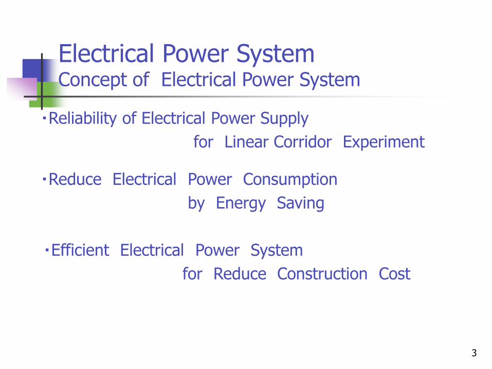
Electrical Power System Concept of Electrical Power System
・Reliability of Electrical Power Supply
for Linear Corridor Experiment
・Reduce Electrical Power Consumption
by Energy Saving
・Efficient Electrical Power System
for Reduce Construction Cost
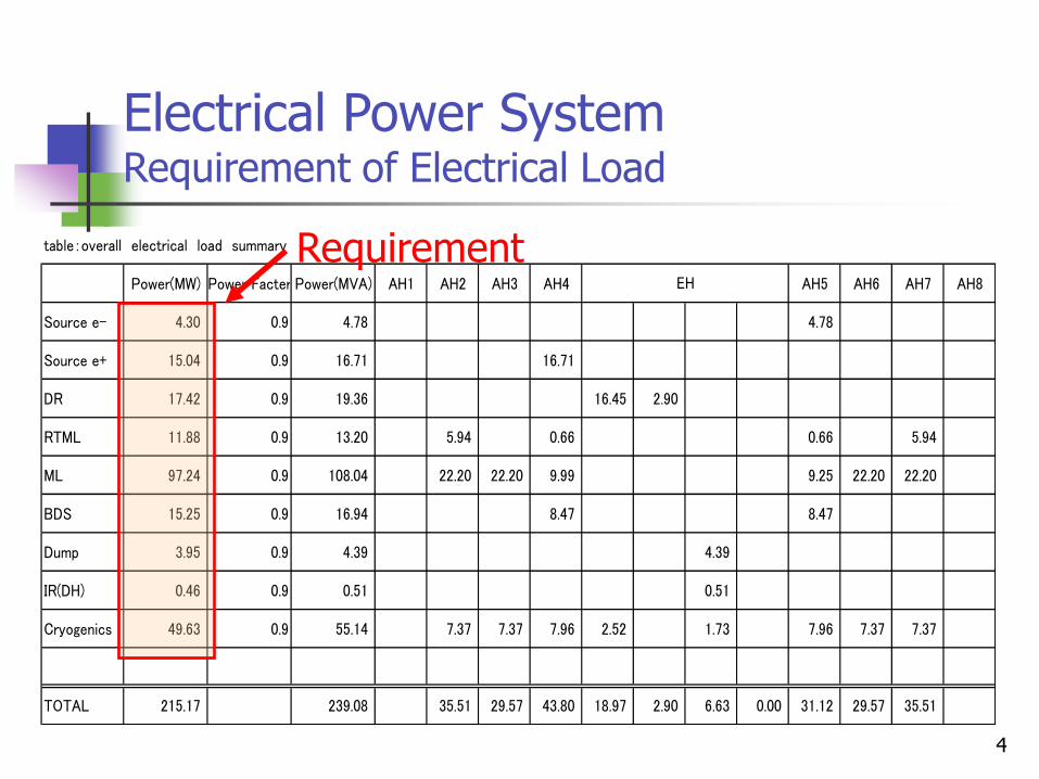
4
table:overall electrical load summary
Power(MW) Power Facter Power(MVA) AH1 AH2 AH3 AH4 AH5 AH6 AH7 AH8
Source e- 4.30 0.9 4.78 4.78
Source e+ 15.04 0.9 16.71 16.71
DR 17.42 0.9 19.36 16.45 2.90
RTML 11.88 0.9 13.20 5.94 0.66 0.66 5.94
ML 97.24 0.9 108.04 22.20 22.20 9.99 9.25 22.20 22.20
BDS 15.25 0.9 16.94 8.47 8.47
Dump 3.95 0.9 4.39 4.39
IR(DH) 0.46 0.9 0.51 0.51
Cryogenics 49.63 0.9 55.14 7.37 7.37 7.96 2.52 1.73 7.96 7.37 7.37
TOTAL 215.17 239.08 35.51 29.57 43.80 18.97 2.90 6.63 0.00 31.12 29.57 35.51
EH
Electrical Power System Requirement of Electrical Load
Requirement
5
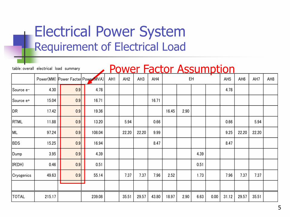
Electrical Power System Requirement of Electrical Load
Power Factor Assumption table:overall electrical load summary
Power(MW) Power Facter Power(MVA) AH1 AH2 AH3 AH4 AH5 AH6 AH7 AH8
Source e- 4.30 0.9 4.78 4.78
Source e+ 15.04 0.9 16.71 16.71
DR 17.42 0.9 19.36 16.45 2.90
RTML 11.88 0.9 13.20 5.94 0.66 0.66 5.94
ML 97.24 0.9 108.04 22.20 22.20 9.99 9.25 22.20 22.20
BDS 15.25 0.9 16.94 8.47 8.47
Dump 3.95 0.9 4.39 4.39
IR(DH) 0.46 0.9 0.51 0.51
Cryogenics 49.63 0.9 55.14 7.37 7.37 7.96 2.52 1.73 7.96 7.37 7.37
TOTAL 215.17 239.08 35.51 29.57 43.80 18.97 2.90 6.63 0.00 31.12 29.57 35.51
EH
6
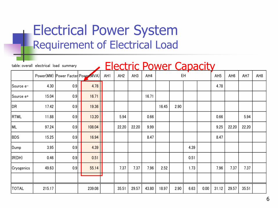
Electrical Power System Requirement of Electrical Load
Electric Power Capacity table:overall electrical load summary
Power(MW) Power Facter Power(MVA) AH1 AH2 AH3 AH4 AH5 AH6 AH7 AH8
Source e- 4.30 0.9 4.78 4.78
Source e+ 15.04 0.9 16.71 16.71
DR 17.42 0.9 19.36 16.45 2.90
RTML 11.88 0.9 13.20 5.94 0.66 0.66 5.94
ML 97.24 0.9 108.04 22.20 22.20 9.99 9.25 22.20 22.20
BDS 15.25 0.9 16.94 8.47 8.47
Dump 3.95 0.9 4.39 4.39
IR(DH) 0.46 0.9 0.51 0.51
Cryogenics 49.63 0.9 55.14 7.37 7.37 7.96 2.52 1.73 7.96 7.37 7.37
TOTAL 215.17 239.08 35.51 29.57 43.80 18.97 2.90 6.63 0.00 31.12 29.57 35.51
EH
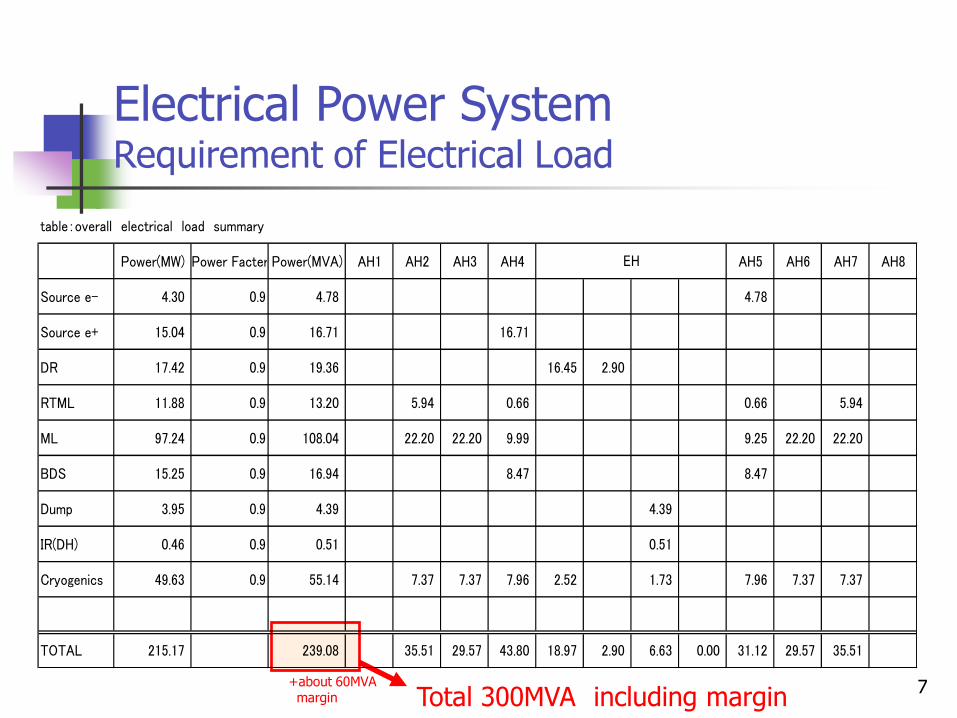
7
Electrical Power System Requirement of Electrical Load
Total 300MVA including margin
table:overall electrical load summary
Power(MW) Power Facter Power(MVA) AH1 AH2 AH3 AH4 AH5 AH6 AH7 AH8
Source e- 4.30 0.9 4.78 4.78
Source e+ 15.04 0.9 16.71 16.71
DR 17.42 0.9 19.36 16.45 2.90
RTML 11.88 0.9 13.20 5.94 0.66 0.66 5.94
ML 97.24 0.9 108.04 22.20 22.20 9.99 9.25 22.20 22.20
BDS 15.25 0.9 16.94 8.47 8.47
Dump 3.95 0.9 4.39 4.39
IR(DH) 0.46 0.9 0.51 0.51
Cryogenics 49.63 0.9 55.14 7.37 7.37 7.96 2.52 1.73 7.96 7.37 7.37
TOTAL 215.17 239.08 35.51 29.57 43.80 18.97 2.90 6.63 0.00 31.12 29.57 35.51
EH
+about 60MVA margin
8
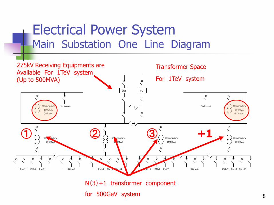
Electrical Power System Main Substation One Line Diagram
VCT VCT
275KV/66KV
100MVA
(in futre)
(in future)
275KV/66KV
100MVA
275KV/66KV
100MVA
275KV/66KV
100MVA
275KV/66KV
100MVA
275KV/66KV
100MVA
(in future)
(in future)
PM-11 PM-9 PM-7 PM*-0 PM-11 PM-9 PM-7 PM*-0 PM+7 PM+9 PM+11 PM+7 PM+9 PM+11
Transformer Space
For 1TeV system
N(3)+1 transformer component
for 500GeV system
① ② ③ +1
275kV Receiving Equipments are Available For 1TeV system (Up to 500MVA)
9
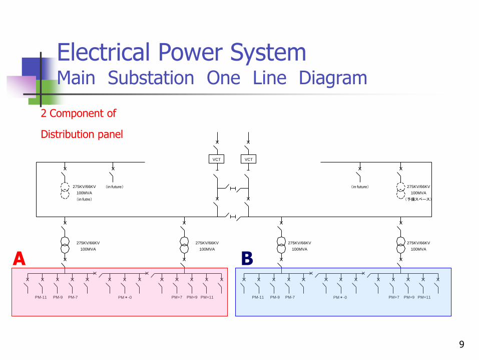
Electrical Power System Main Substation One Line Diagram
VCT VCT
275KV/66KV
100MVA
(in futre)
(in future)
275KV/66KV
100MVA
275KV/66KV
100MVA
275KV/66KV
100MVA
275KV/66KV
100MVA
275KV/66KV
100MVA
(予備スペース)
(in future)
PM-11 PM-9 PM-7 PM*-0 PM-11 PM-9 PM-7 PM*-0 PM+7 PM+9 PM+11 PM+7 PM+9 PM+11
A B
2 Component of
Distribution panel
10
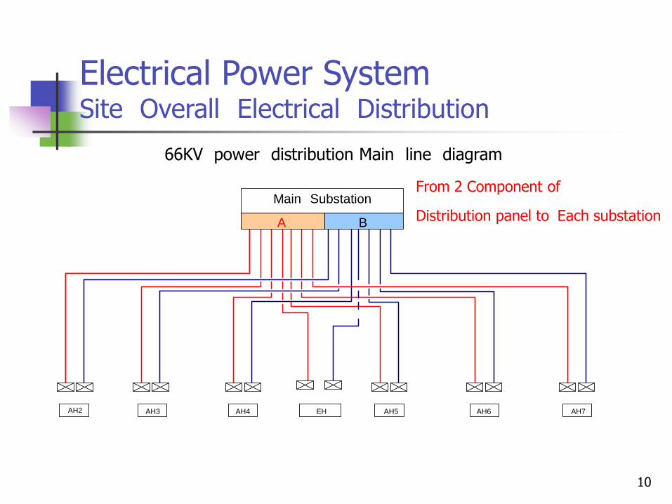
Electrical Power System Site Overall Electrical Distribution
66KV power distribution Main line diagram
AH2 AH3 AH4 EH AH5 AH6 AH7
A B
Main Substation From 2 Component of
Distribution panel to Each substation
11
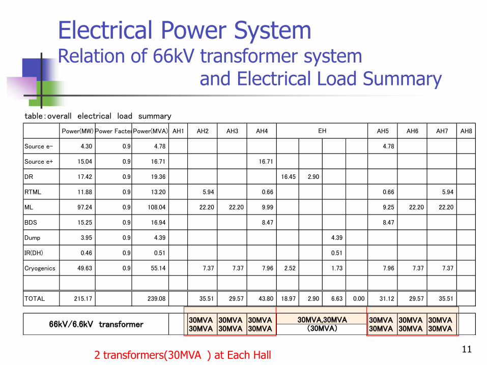
Electrical Power System Relation of 66kV transformer system and Electrical Load Summary
2 transformers(30MVA ) at Each Hall
table:overall electrical load summary
Power(MW) Power FacterPower(MVA) AH1 AH2 AH3 AH4 AH5 AH6 AH7 AH8
Source e- 4.30 0.9 4.78 4.78
Source e+ 15.04 0.9 16.71 16.71
DR 17.42 0.9 19.36 16.45 2.90
RTML 11.88 0.9 13.20 5.94 0.66 0.66 5.94
ML 97.24 0.9 108.04 22.20 22.20 9.99 9.25 22.20 22.20
BDS 15.25 0.9 16.94 8.47 8.47
Dump 3.95 0.9 4.39 4.39
IR(DH) 0.46 0.9 0.51 0.51
Cryogenics 49.63 0.9 55.14 7.37 7.37 7.96 2.52 1.73 7.96 7.37 7.37
TOTAL 215.17 239.08 35.51 29.57 43.80 18.97 2.90 6.63 0.00 31.12 29.57 35.51
30MVA30MVA
30MVA30MVA
30MVA30MVA
30MVA30MVA
30MVA30MVA
30MVA30MVA
30MVA,30MVA(30MVA)66kV/6.6kV transformer
EH
12
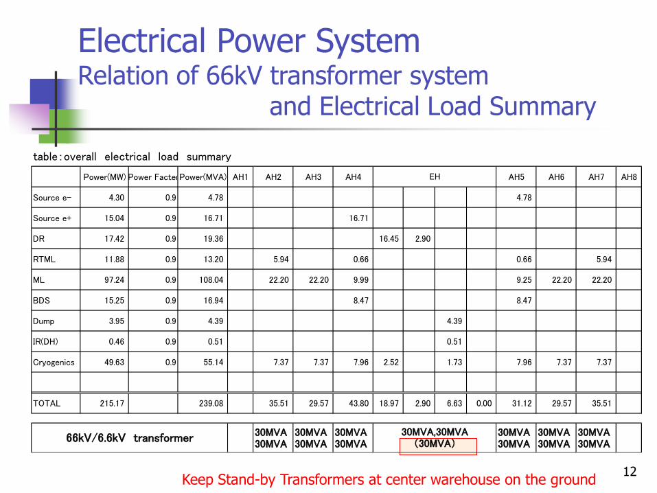
Electrical Power System Relation of 66kV transformer system and Electrical Load Summary
Keep Stand-by Transformers at center warehouse on the ground
table:overall electrical load summary
Power(MW) Power FacterPower(MVA) AH1 AH2 AH3 AH4 AH5 AH6 AH7 AH8
Source e- 4.30 0.9 4.78 4.78
Source e+ 15.04 0.9 16.71 16.71
DR 17.42 0.9 19.36 16.45 2.90
RTML 11.88 0.9 13.20 5.94 0.66 0.66 5.94
ML 97.24 0.9 108.04 22.20 22.20 9.99 9.25 22.20 22.20
BDS 15.25 0.9 16.94 8.47 8.47
Dump 3.95 0.9 4.39 4.39
IR(DH) 0.46 0.9 0.51 0.51
Cryogenics 49.63 0.9 55.14 7.37 7.37 7.96 2.52 1.73 7.96 7.37 7.37
TOTAL 215.17 239.08 35.51 29.57 43.80 18.97 2.90 6.63 0.00 31.12 29.57 35.51
30MVA30MVA
30MVA30MVA
30MVA30MVA
30MVA30MVA
30MVA30MVA
30MVA30MVA
30MVA,30MVA(30MVA)66kV/6.6kV transformer
EH
13
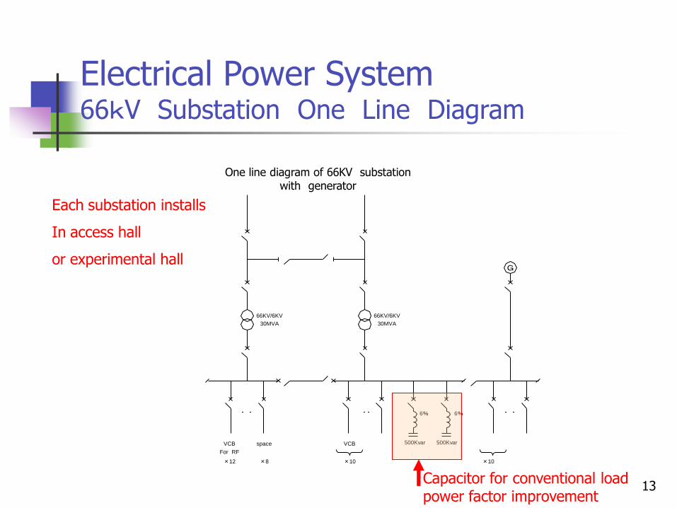
Electrical Power System 66kV Substation One Line Diagram
One line diagram of 66KV substation with generator
Each substation installs
In access hall
or experimental hall
66KV/6KV
30MVA
66KV/6KV
30MVA
6% 6%
VCB
For RF
500Kvar 500Kvar
×12
space
×8
VCB
×10 ×10
Capacitor for conventional load power factor improvement
14
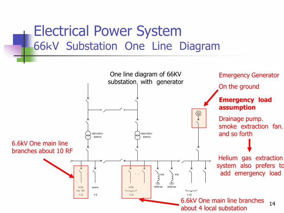
Electrical Power System 66kV Substation One Line Diagram
One line diagram of 66KV substation with generator
Emergency Generator
On the ground
66KV/6KV
30MVA
66KV/6KV
30MVA
6% 6%
VCB
For RF
500Kvar 500Kvar
×12
space
×8
VCB
×10 ×10
6.6kV One main line branches about 10 RF
6.6kV One main line branches about 4 local substation
Emergency load assumption
Drainage pump, smoke extraction fan, and so forth
Helium gas extraction system also prefers to add emergency load
15
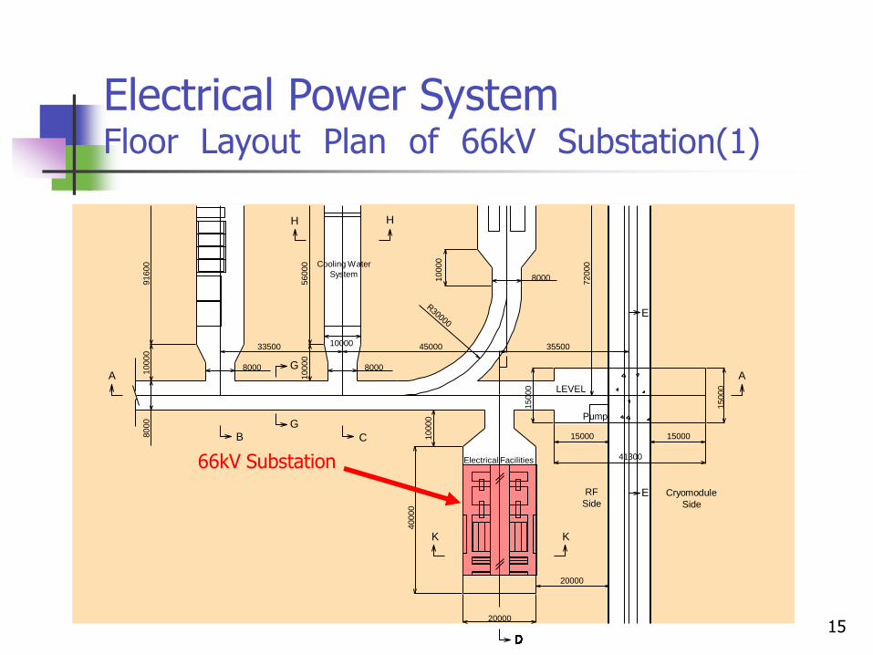
Electrical Power System Floor Layout Plan of 66kV Substation(1)
A
G
Cooling Water
System
H H
B
G
C
K K
E
E
LEVEL
Pump
RF
Side Cryomodule
Side
Electrical Facilities
A
8000
10000
91600
56000
10000
10000
8000
33500
8000
45000
10000
8000
72000
35500
15000
15000 15000
15000
41300
10000
40000
20000
20000
66kV Substation
16
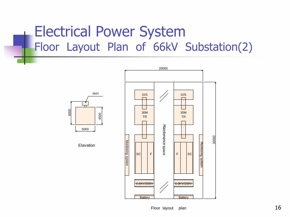
Electrical Power System Floor Layout Plan of 66kV Substation(2)
5000
6000
4500
duct
Elavation
GIS
20000
30000
30M
TR
Monito
ring s
yste
m
SC F
6.6KV/200V
Battery
Monito
ring syste
m
GIS
30M
TR
F SC
Floor layout plan
Main
tenance
space
6.6KV/200V
Battery
17
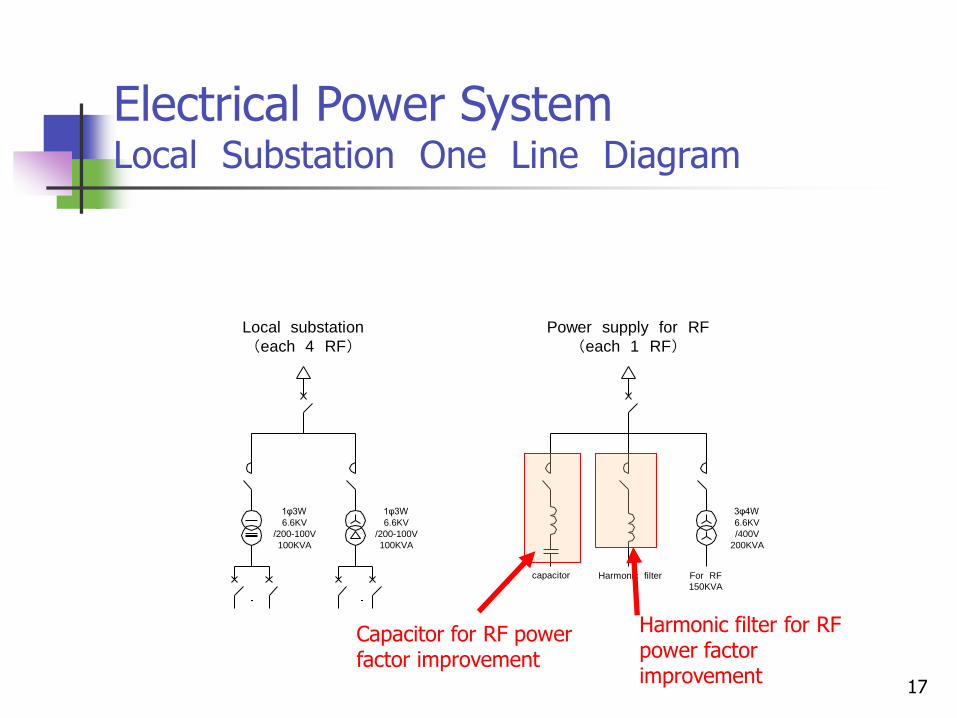
Electrical Power System Local Substation One Line Diagram
1φ3W
6.6KV
/200-100V
100KVA
1φ3W
6.6KV
/200-100V
100KVA
3φ4W
6.6KV
/400V
200KVA
capacitor Harmonic filter For RF
150KVA
Local substation
(each 4 RF)
Power supply for RF
(each 1 RF)
Capacitor for RF power factor improvement
Harmonic filter for RF power factor improvement
18
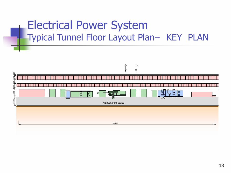
Electrical Power System Typical Tunnel Floor Layout Planー KEY PLAN
16
00
1
60
0
10
00
50
0
80
0
20
0
38000
A B
Maintenance space
19
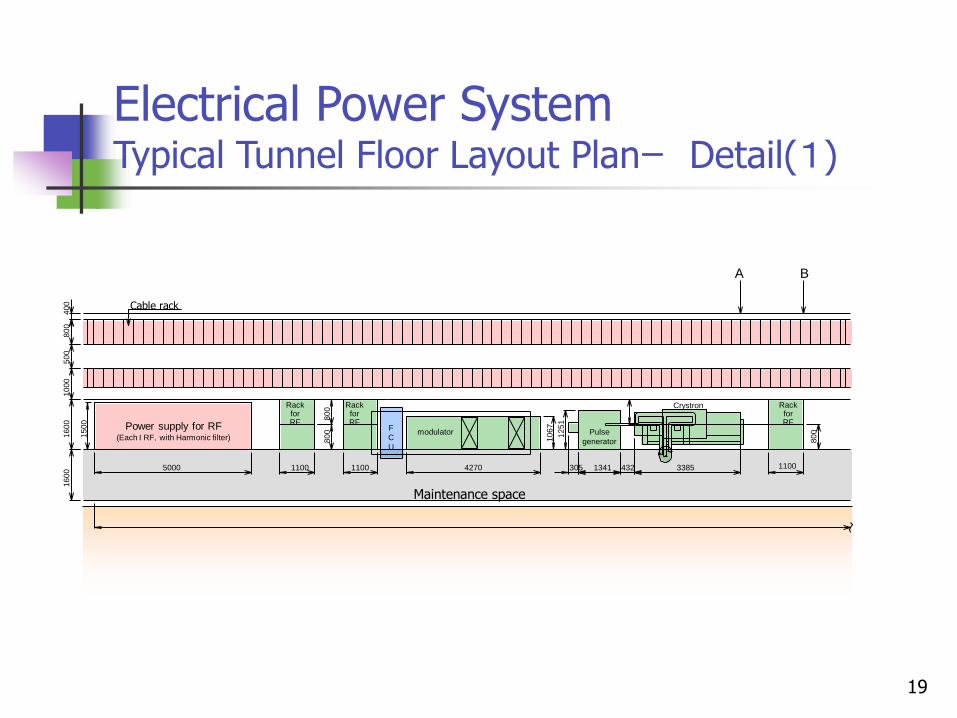
Electrical Power System Typical Tunnel Floor Layout Planー Detail(1)
Cable rack
F
C
U
Pulse
generator
Crystron
modulator
Rack for RF Power supply for RF
(Each I RF,with Harmonic filter)
Rack for RF
Rack for RF
15
00
16
00
1
60
0
10
00
5
00
8
00
40
0
1100 1100 4270 5000 305 1341 432 3385
80
0
80
0
10
67
12
51
1100
80
0
A B
Maintenance space
20
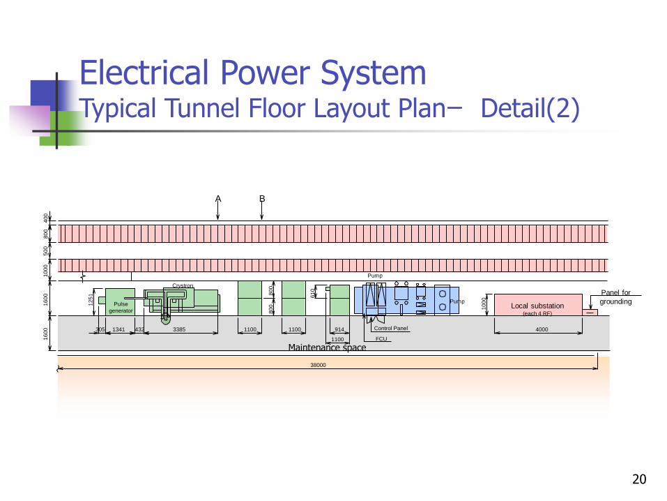
Electrical Power System Typical Tunnel Floor Layout Planー Detail(2)
Pump
Control Panel
FCU
Local substation (each 4 RF)
Panel for
grounding Pulse
generator
Crystron
Pump
A B
50
0
80
0
40
0
16
00
1
60
0
10
00
12
51
305 1341 432 3385 1100 1100 914
80
0
80
0
38000
61
0
10
00
4000
1100
Maintenance space
21
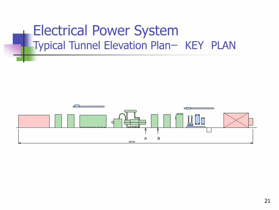
Electrical Power System Typical Tunnel Elevation Planー KEY PLAN
A B 38000
22
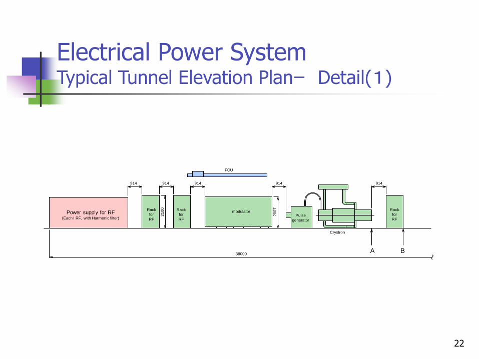
Electrical Power System Typical Tunnel Elevation Planー Detail(1)
Pulse
generator
modulator Rack
for
RF
Power supply for RF (Each I RF,with Harmonic filter)
Rack
for
RF
Rack
for
RF
Crystron
914 914 914
FCU
20
07
914 914
A B
21
00
38000
23
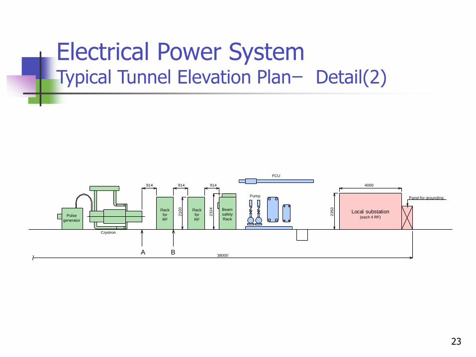
Electrical Power System Typical Tunnel Elevation Planー Detail(2)
Beam
safety
Rack
FCU
A B
4000
23
50
914 914
23
24
21
00
914
38000
Pulse
generator
Crystron
Rack
for
RF
Rack
for
RF
Pump
Local substation (each 4 RF)
Panel for grounding
24
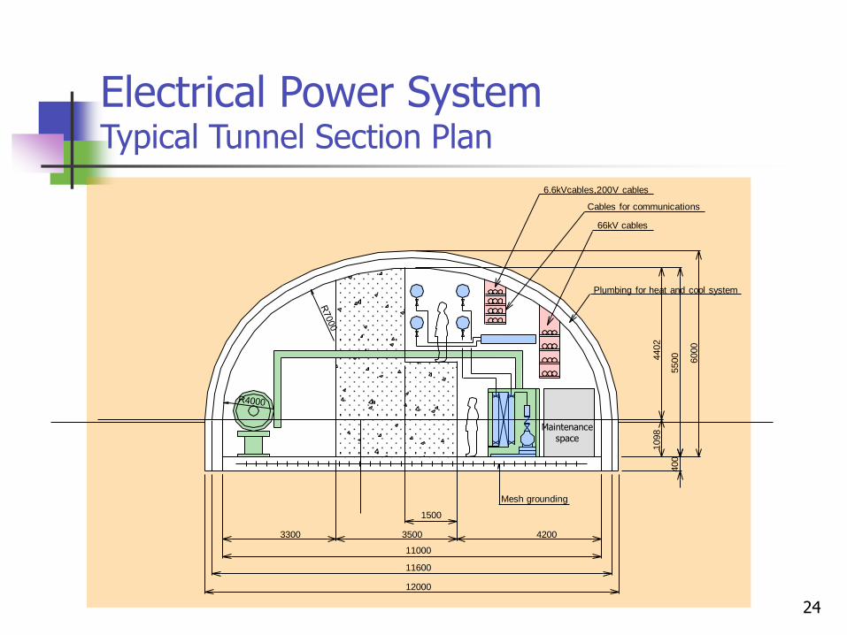
Electrical Power System Typical Tunnel Section Plan
400
1098
4402
5500
6000
Plumbing for heat and cool system
Mesh grounding
6.6kVcables,200V cables
Cables for communications
66kV cables
3300 3500
1500
4200
11000
11600
12000
Maintenance space
25
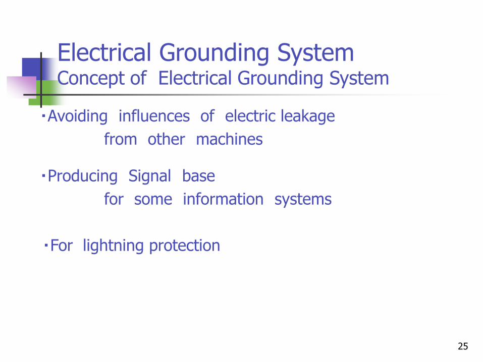
Electrical Grounding System Concept of Electrical Grounding System
・Avoiding influences of electric leakage
from other machines
・Producing Signal base
for some information systems
・For lightning protection
26
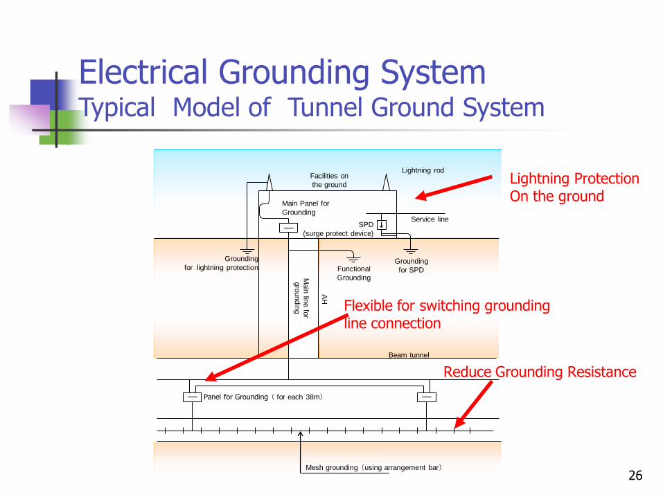
Electrical Grounding System Typical Model of Tunnel Ground System
Mesh grounding (using arrangement bar)
Panel for Grounding ( for each 38m)
Beam tunnel
AH
Main
line fo
r
gro
undin
g
Grounding
for lightning protection Functional
Grounding
Grounding
for SPD
Service line SPD
(surge protect device)
Main Panel for
Grounding
Facilities on
the ground
Lightning rod
Reduce Grounding Resistance
Flexible for switching grounding line connection
Lightning Protection On the ground
27
Communication Network System Abstract
・Reliability of Information system
・Reduce Space by Unified wiring management
・Efficient Information System
for Reduce Construction Cost
28
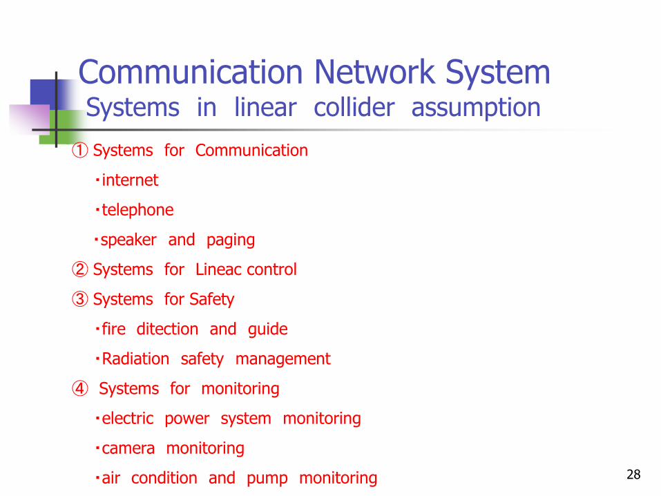
Communication Network System Systems in linear collider assumption ① Systems for Communication
・internet
・telephone
・speaker and paging
② Systems for Lineac control
③ Systems for Safety
・fire ditection and guide
・Radiation safety management
④ Systems for monitoring
・electric power system monitoring
・camera monitoring
・air condition and pump monitoring
29
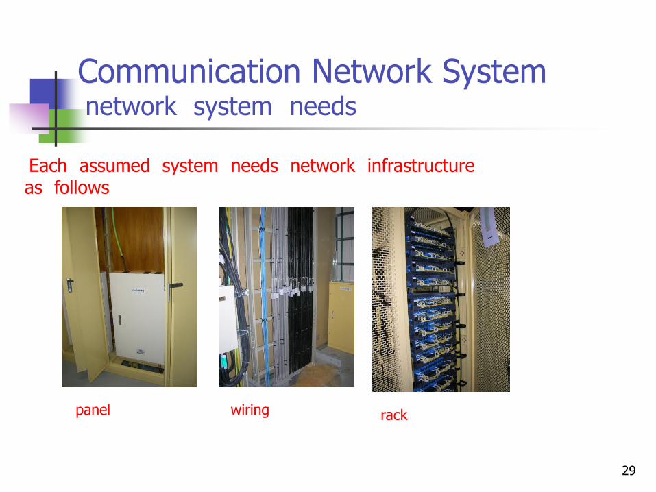
Communication Network System network system needs
Each assumed system needs network infrastructure as follows
panel wiring rack
30
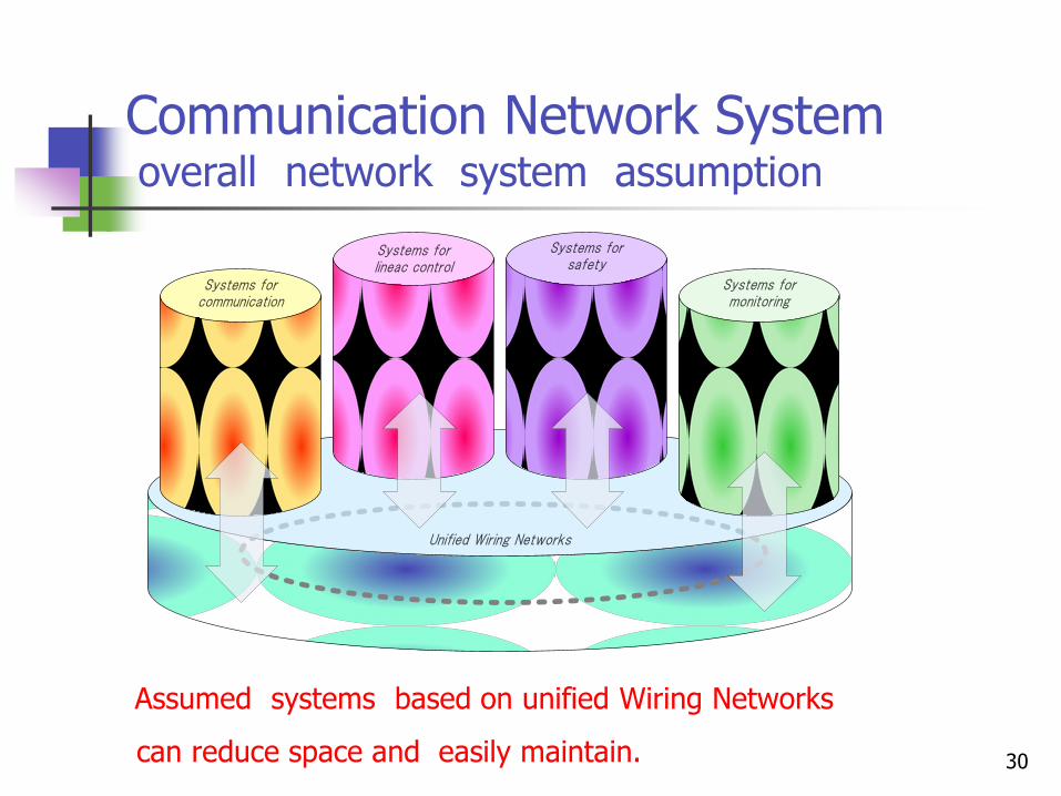
Communication Network System overall network system assumption
Unified Wiring Networks
Systems for communication
Systems for lineac control
Systems forsafety
Systems formonitoring
Assumed systems based on unified Wiring Networks
can reduce space and easily maintain.

![REFERENCE DESIGN REPORT ILC Global Design E ort · PDF fileINTERNATIONAL LINEAR COLLIDER REFERENCE DESIGN REPORT ILC Global Design E ort and World Wide Study arXiv:0712.1950v1 [ ]](https://img.pdfslide.net/doc/110x75/5ab5f4ee7f8b9a1a048d6378/reference-design-report-ilc-global-design-e-ort-linear-collider-reference-design.jpg)