Embed Size (px)
Citation preview

Linear Collider Flavour Identification Collaboration:Case for Support
■ Introduction to the ILC and LCFI:
♦ Physics at the ILC
♦ LCFI physics studies
♦ Sensor design and testing
♦ Mechanical studies
■ Proposed LCFI programme:
♦ WP1 Simulation and physics studies
♦ WP2 Sensor development
♦ WP3 Readout and drive electronics
♦ WP4 External electronics
♦ WP5 Integration and testing
♦ WP6 Vertex detector mechanical studies
♦ WP7 Test-beam and EMI studies
LCFI Collaboration
P Allport3, D Bailey1, C Buttar2, D Cussans1, CJS Damerell3, J Fopma4, B Foster4, S Galagedera5, AR Gillman5, J Goldstein5, T Greenshaw3, R Halsall5, B Hawes4,
K Hayrapetyan3, H Heath1, S Hillert4, D Jackson4,5, EL Johnson5, N Kundu4, AJ Lintern5, P Murray5 A Nichols5, A Nomerotski4, V O’Shea2, C Parkes2, C Perry4,
KD Stefanov5, SL Thomas5, R Turchetta5, M Tyndel5, J Velthuis3, G Villani5, S Worm5, S Yang4.
1 Bristol University2 Glasgow University3 Liverpool University4 Oxford University5 Rutherford Appleton Laboratory
The International Linear Collider
■ Standard Model of particle physics is clearly incomplete.
■ From 2007, LHC experiments will study pp collisions √s = 14 TeV giving large mass reach for discovery of new physics.
■ Precision measurement (of masses, branching ratios etc.) complicated by hadronic environment.
■ International consensus: e+e LC operating at up to √s ~ 1 TeV needed in parallel with the LHC, i.e. start-up in next decade.
■ Detailed case presented by LHC/LC Study Group: hep-ph/0410364.
■ International Technology Review Panel recommended in August 2004 that superconducting technology be used for accelerating cavities.
■ Global effort now underway to design SC ILC, director Barry Barish.
■ Timeline defined by ILC Steering Group foresees formation of experimental collaborations in 2008 and writing of Technical Design Reports in 2009.
■ Agreement that vertex detector technology be chosen following “ladder” tests in 2010.
Flavour and quark charge identification at the ILC
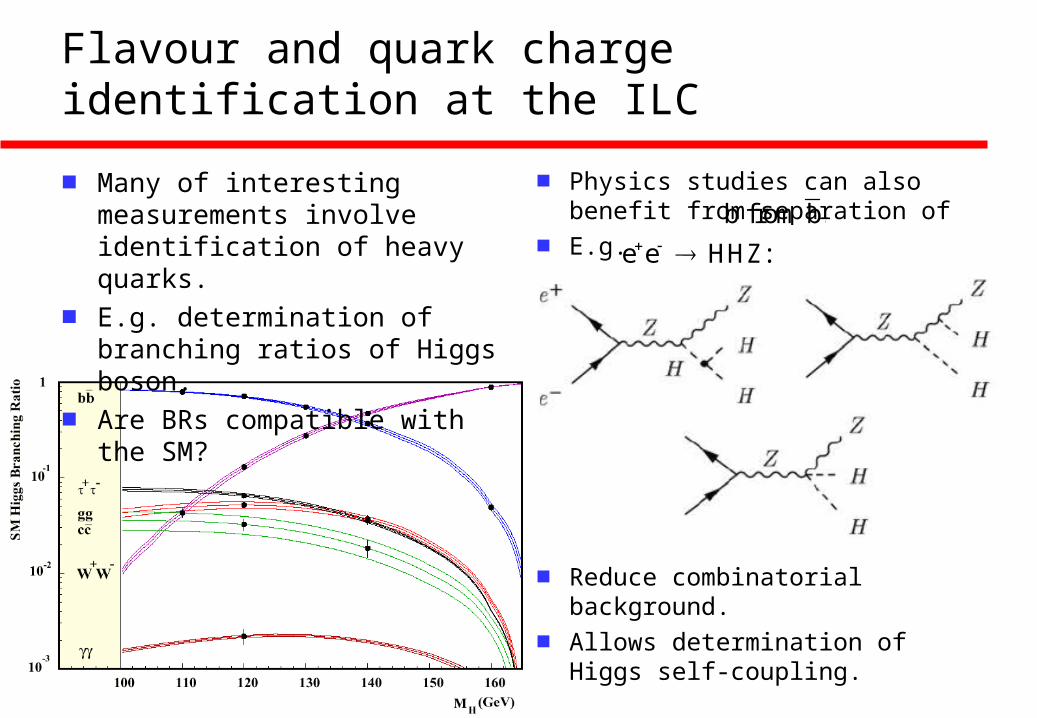
■ Many of interesting measurements involve identification of heavy quarks.
■ E.g. determination of branching ratios of Higgs boson.
■ Are BRs compatible with the SM?
■ Physics studies can also benefit from separation of
■ E.g.
■ Reduce combinatorial background.
■ Allows determination of Higgs self-coupling.
b from b.
e e HHZ:

Quark charge identification
■ Increases sensitivity to new physics.
■ E.g. effects of large extra dimensions on
■ Study ALR = (L – R)/tot as a function of cos .
■ For muons, effects of ED not visible:
■ Changes much more pronounced for c (and b) quarks:
■ Requires efficient charge determination to large cos .
e e ff .

Quark charge identification
■ Provides new tools for physics studies.
■ E.g. measure top polarisation in decay
■ Top decays before hadronisation.
■ Anti-strange jet has 1 – cos distribution w.r.t. top polarisation direction.
■ Distinguish between t and by tagging b and c jets and determining quark charge for (at least) one of these jets.
■ Example of physics made accessible using this technique:
■ Determine tan and tri-linear couplings Ab and At through measurements of top polarisation in
t W b
cs
c
t
W+
b
t0
s
b and t decays.
t

Vertex detector performance goals
■ Average impact parameter of B decay products ~ 300 m, of charmed particles less than 100 m.
■ resolution given by convolution of point precision, multiple scattering, lever arm and mechanical stability.
■ Multiple scattering significant despite large √s at ILC as charged track momenta extend down to ~ 1 GeV.
■ Resolve all tracks in dense jets.
■ Cover largest possible solid angle: forward/backward events are of particular significance for studies with polarised beams.
■ Stand-alone reconstruction desirable.
■ Implies typically:
♦ Pixels ~ 20 x 20 m2
♦ Hit resolution better than 5 m.
♦ First measurement at r ~ 15 mm.
♦ Five layers out to radius of about 60 mm, i.e. total ~ 109 pixels
♦ Material ~ 0.1% X0 per layer.
♦ Detector covers |cos < 0.96.
B
B
track 2 track 1

Constraints due to machine and detector
■ Minimum beam pipe radius 14 mm.
■ Pair background at this radius in ~ 4T field causes 0.03 (0.05) hits per BC and mm2 at √s = 500 (800) GeV.
■ Bunch train structure:
■ For 109 pixels of size 20 x 20 m2, implies readout or storage of signals ~ 20 times during bunch train to obtain occupancy less than ~ 0.3 (0.9) %.
■ Must withstand:
♦ Radiation dose due to pair background of ~ 20 krad p.a.
♦ Annual dose of neutrons from beam and beamstrahlung dumps ~ 1 x 10⁹ 1 MeV equiv. n/cm2.
■ Must cope with operation in 4T field.
■ Must be robust against beam-related RF pickup and noise from other detectors.
337 (189) ns
2820 (4500)
0.2 s
0.95 ms

Conceptual vertex detector design
■ Here using CCDs:
■ VXD surrounded by ~ 2 mm thick Be support cylinder.
■ Allows Be beam pipe to be of thickness of ~ 0.25 mm.
■ Pixel size 20 x 20 m2, implies about 109 pixels in total.
■ Standalone tracking using outer 4 layers.
■ Hits in first layer improve extrapolation of tracks to IP.
■ Readout and drive connections routed along BP.
■ Important that access to vertex detector possible.
Conceptual detector design
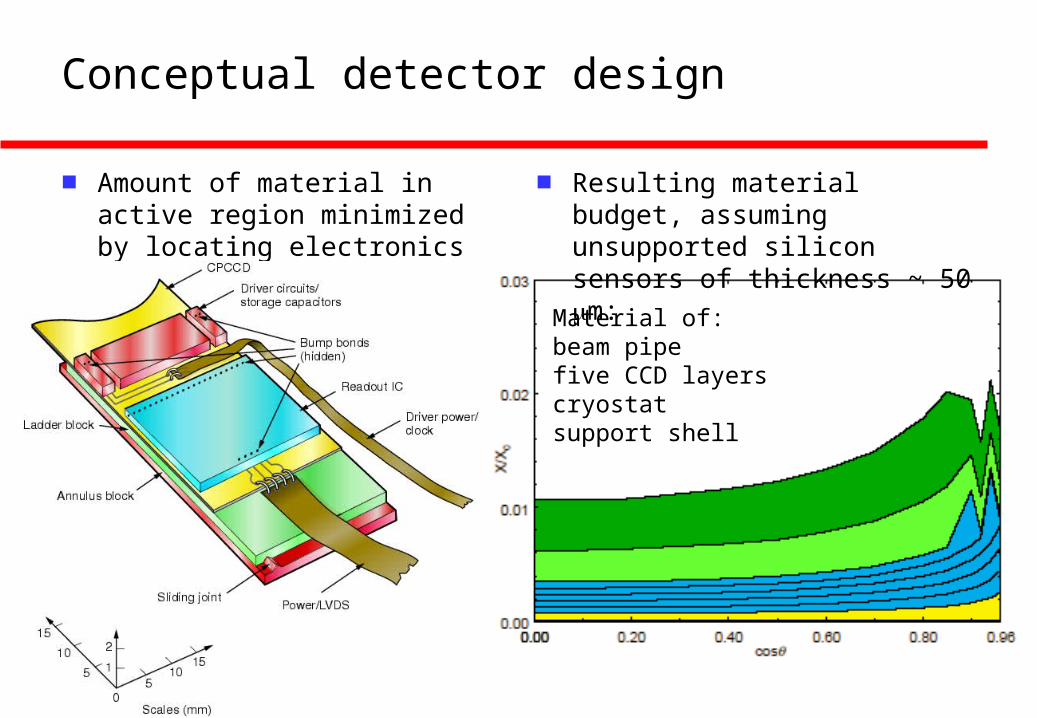
■ Amount of material in active region minimized by locating electronics only at ends of ladders.
■ Resulting material budget, assuming unsupported silicon sensors of thickness ~ 50 m:
Material of:beam pipefive CCD layerscryostatsupport shell
Vertex detector performance – impact parameter
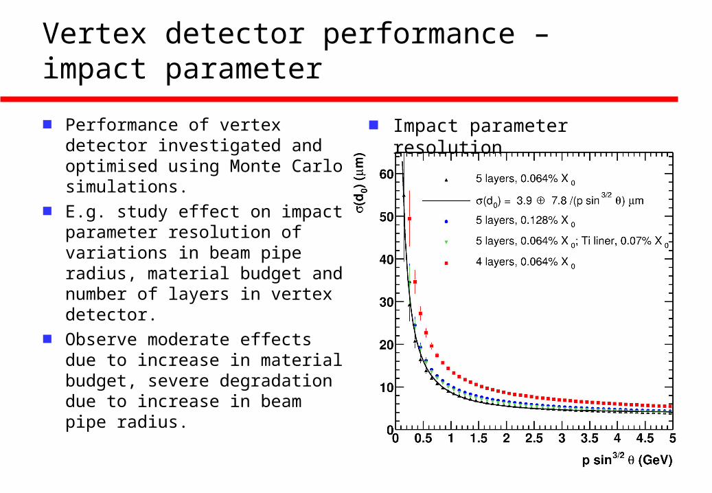
■ Performance of vertex detector investigated and optimised using Monte Carlo simulations.
■ E.g. study effect on impact parameter resolution of variations in beam pipe radius, material budget and number of layers in vertex detector.
■ Observe moderate effects due to increase in material budget, severe degradation due to increase in beam pipe radius.
■ Impact parameter resolution
Flavour identification performance
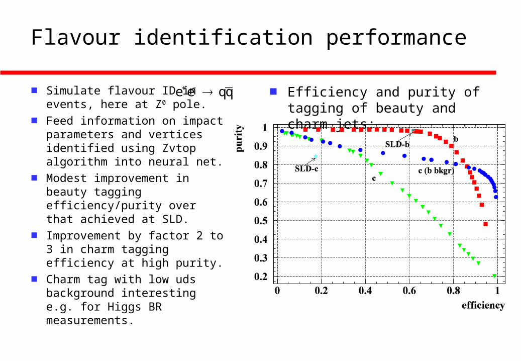
■ Simulate flavour ID inevents, here at Z0 pole.
■ Feed information on impact parameters and vertices identified using Zvtop algorithm into neural net.
■ Modest improvement in beauty tagging efficiency/purity over that achieved at SLD.
■ Improvement by factor 2 to 3 in charm tagging efficiency at high purity.
■ Charm tag with low uds background interesting e.g. for Higgs BR measurements.
■ Efficiency and purity of tagging of beauty and charm jets:
e e qq

Quark charge identification performance
■ Must assign all charged tracks to correct vertex.
■ Multiple scattering critical, lowest track momenta ~ 1 GeV.
■ Sum charges associated with b vertex:
■ Quark charge identification for neutral B requires “dipole” algorithm.

Sensors for the vertex detector – CCDs
■ Standard CCDs cannot achieve necessary readout speed
■ LCFI developed Column Parallel CCD with e2v technologies.
Sensors – CPCCD
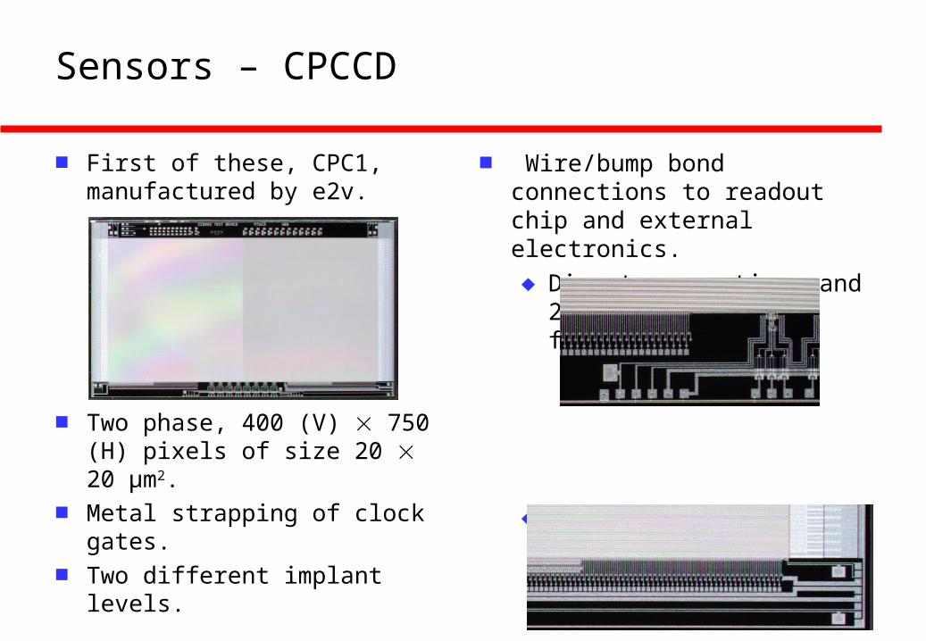
■ First of these, CPC1, manufactured by e2v.
■ Two phase, 400 (V) 750 (H) pixels of size 20 20 μm2.
■ Metal strapping of clock gates.
■ Two different implant levels.
■ Wire/bump bond connections to readout chip and external electronics.
♦ Direct connections and 2-stage source followers:
♦ Direct connections and single stage source followers (20 m pitch):

Sensors – CPC1 and CPR1
■ Standalone CPC1 tests:
■ Noise ~ 100 e (60 e after filter).
■ Minimum clock potential ~1.9 V.
■ Max clock frequency above 25 MHz (design 1 MHz).
■ Limitation caused by asymm. clock signals due to single metal design.
■ Marry with CMOS CPCCD readout ASIC, CPR1 (RAL):
■ IBM 0.25 μm process.
■ 250 parallel channels, 20 μm pitch.
■ Designed for 50 MHz.

Sensors – CPC1 and CPR1
■ Bump bonding of CPC1 and CPR1done at VTT:
■ CPR1 bump bonded to CPC1, signal from charge channels:
■ Observe ~ 70 mV signal, expected 80 mV, good agreement.
CCD radiation hardness tests
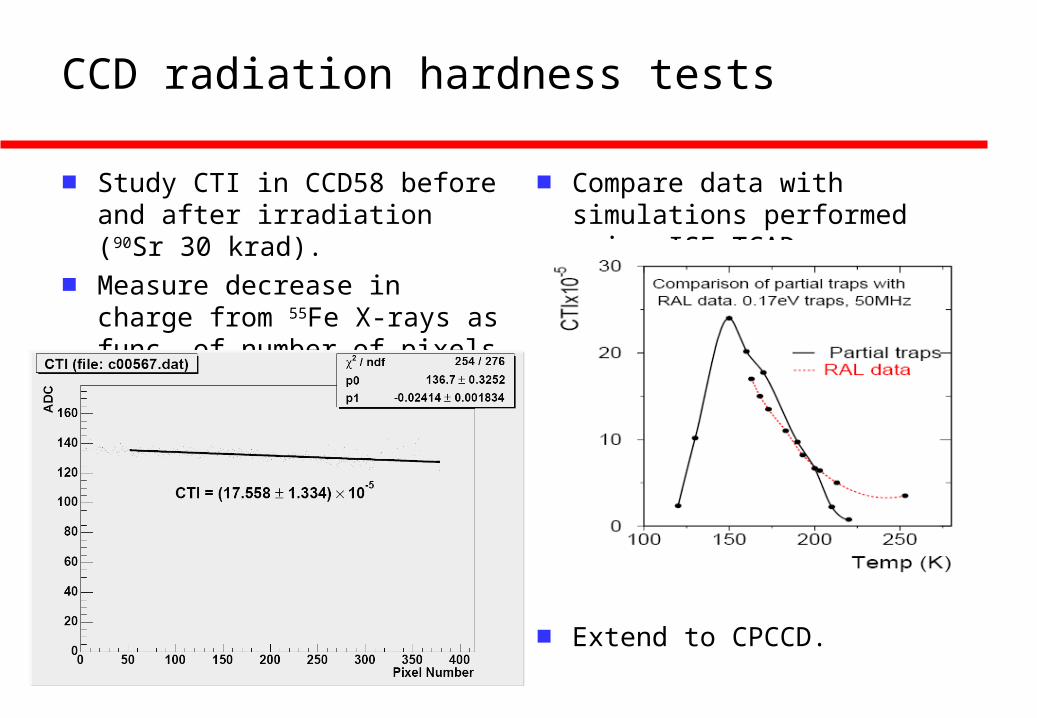
■ Study CTI in CCD58 before and after irradiation (90Sr 30 krad).
■ Measure decrease in charge from 55Fe X-rays as func. of number of pixels through which charge transferred.
■ Compare data with simulations performed using ISE-TCAD.
■ Extend to CPCCD.

Sensors – ISIS
■ In-situ storage image sensor.
■ Signal collected on photogate.
■ Transferred to small CCD register in pixel.
■ Signal charge always buried in silicon until bunch train has passed.
■ Column parallel readout at ~ 1 MHz sufficient to read out before arrival of next bunch train.
■ ISIS1 being built by e2v.
■ 40 160 μm2 cell containing 3-phase CCD with 5 pixels.

Vreset Vdd
Out
Select
Reset
Sensors – FAPS
■ Monolithic Active Pixel Sensors developed within UK.
■ Ongoing development for scientific applications by MI3 collaboration.
■ Storage capacitors added to pixels to allow use at ILC, Flexible Active Pixel Sensors.

Sensors – FAPS
■ Present design “proof of principle”.
■ Pixels 20 x 20 m2, 3 metal layers, 10 storage cells.
■ Test of FAPS structure with LED:
■ 106Ru source tests:
■ Signal to noise ratio between 14 and 17.
■ MAPS demonstrated to tolerate radiation doses above those expected at ILC.
Mechanical considerations
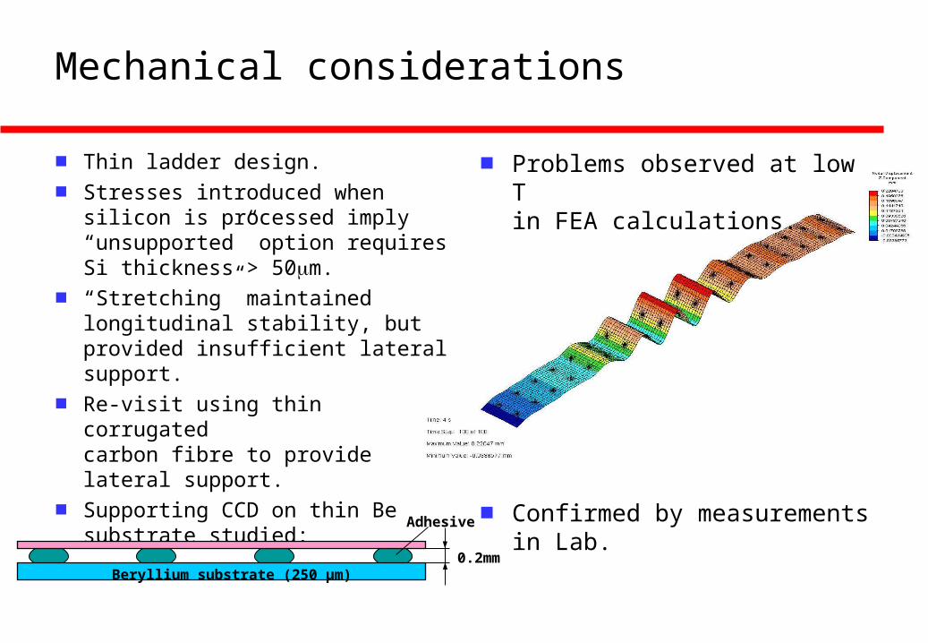
■ Thin ladder design.
■ Stresses introduced when silicon is processed imply “unsupported” option requires Si thickness > 50m.
■ “Stretching” maintained longitudinal stability, but provided insufficient lateral support.
■ Re-visit using thin corrugated carbon fibre to provide lateral support.
■ Supporting CCD on thin Be substrate studied:
■ Problems observed at low Tin FEA calculations.
■ Confirmed by measurements in Lab.
Beryllium substrate (250 μm)
Adhesive
0.2mm
Mechanical considerations
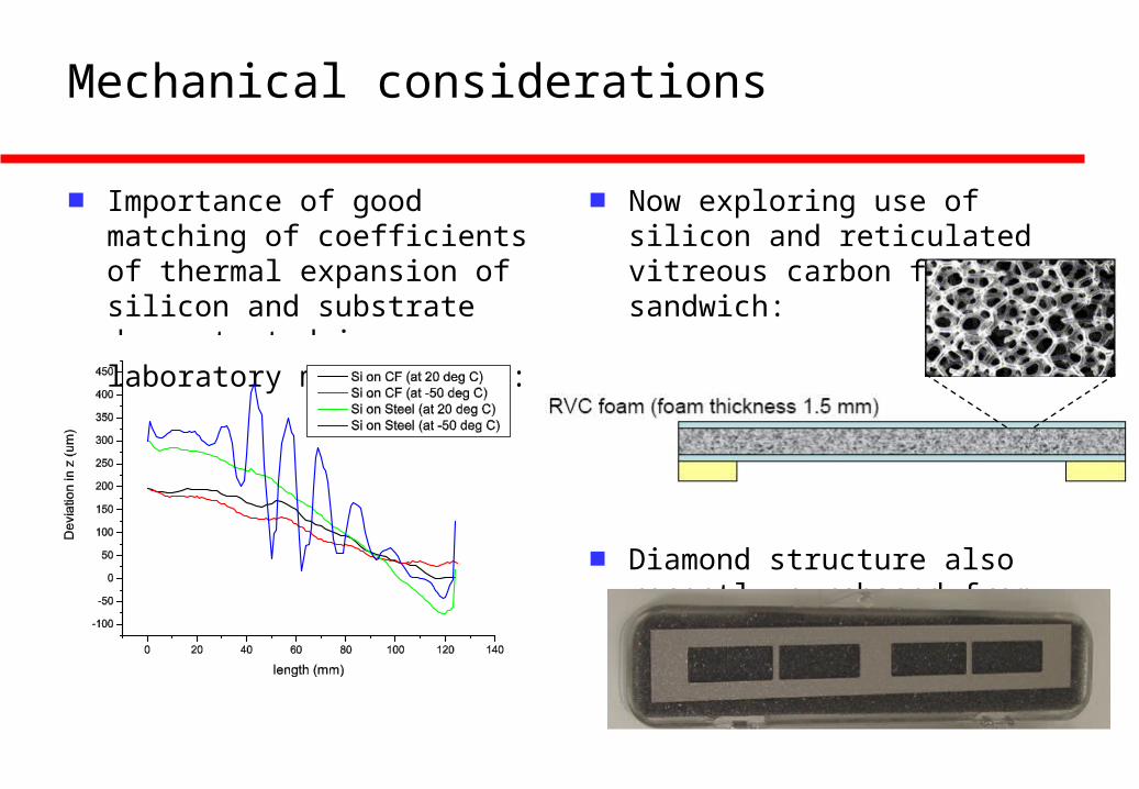
■ Importance of good matching of coefficients of thermal expansion of silicon and substrate demonstrated in laboratory measurements:
■ Now exploring use of silicon and reticulated vitreous carbon foam sandwich:
■ Diamond structure also recently purchased from Element Six:

Summary
■ Progress made in understanding physics accessible with a precise vertex detector at the ILC via:
♦ Flavour identification.
♦ Determination of b, c charge.
■ Column Parallel CCD development progressing:
♦ LCFI will soon have sensors of scale close to that required for the ILC.
♦ A major remaining challenge is the construction of low mass CCD drive circuitry.
■ Studies of ISIS and FAPS storage sensors initiated.
■ Mechanical studies have demonstrated:
♦ Unsupported Si will not result in lowest mass sensors.
♦ Emphasis shifted to new materials.
■ Milestones of previous proposal met or surpassed in last three years.


![knc/ 6] lcfi](https://img.pdfslide.net/doc/110x75/5d51cddd88c993c9398b5421/knc-6-lcfi.jpg)
