Embed Size (px)
Citation preview
CWP-711
Illumination compensation for image-domain wavefieldtomography
Tongning Yang∗, Jeffrey Shragge+, Paul Sava∗∗ Center for Wave Phenomena, Colorado School of Mines+ School of Earth and Environment, University of Western Australia
ABSTRACT
Wavefield tomography represents a family of velocity model building techniques basedon full waveforms as the input and seismic wavefields as the information carrier. Whenthese techniques are implemented in the image domain and use seismic images as theinput, they are referred to as image-domain wavefield tomography. The objective func-tion for image-domain approach is designed to optimize the coherency of reflections inextended common-image gathers. The function applies a penalty operator to the gath-ers, thus highlighting image inaccuracies due to the velocity model error. Minimizingthe objective function optimizes the model and improves the image quality, by makinguse of the gradient of the objective function computed using the adjoint-state method.Uneven illumination is a common problem for complex geological regions, such assub-salt, or the consequence of incomplete data. Imbalanced illumination not only cre-ates shadow zone for migrated images, but also results in defocusing in common-imagegathers even when the migration velocity model is correct. This additional defocus-ing violates the wavefield tomography assumption stating that the migrated imagesare perfectly focused in the case of the correct model. Therefore, defocusing risingfrom illumination mixes with defocusing rising from the model errors and degrades themodel reconstruction. We address this problem by incorporating the illumination ef-fects into the penalty operator such that only the defocusing by model errors is used formodel construction. This method improves the robustness and effectiveness of wave-field tomography applied in the areas characterized by poor illumination. Our syntheticexamples demonstrate that velocity models are more accurately reconstructed by ourmethod using the illumination compensation, leading to more coherent and better fo-cused subsurface images than those in the conventional approach without illuminationcompensation.
Key words: wavefield tomography, illumination compensation, extended images, ad-joint state method
1 INTRODUCTION
Building an accurate and reliable velocity model remains oneof the biggest challenges in current seismic imaging prac-tice. In regions characterized by complex subsurface structure,prestack wave-equation depth migration, (e.g., one-way wave-equation migration or reverse-time migration), is a powerfultool for accurately imaging the earth’s interior (Gray et al.,2001; Etgen et al., 2009). The widespread use of these ad-vanced imaging techniques drives the need for high-quality
velocity models because these migration methods are very sen-sitive to model errors (Symes, 2008; Woodward et al., 2008;Virieux and Operto, 2009).
Wavefield tomography represents a family of techniquesfor velocity model building using seismic wavefields (Taran-tola, 1984; Woodward, 1992; Pratt, 1999; Sirgue and Pratt,2004; Plessix, 2006; Vigh and Starr, 2008; Plessix, 2009;Symes, 2009). The core of wavefield tomography is using awave equation (typically constant density acoustic) to simu-late wavefields as the information carrier. Wavefield tomog-
94 T. Yang, J. Shragge, and P. Sava
raphy is usually implemented in the data domain by adjust-ing the velocity model such that simulated and recorded datamatch (Tarantola, 1984; Pratt, 1999). This match is based onthe strong assumption that the wave equation used for simula-tion is consistent with the physics of the earth. However, thisis unlikely to be the case when the earth is characterized bystrong (poro)elasticity. Significant effort is often directed to-ward removing the components of the recorded data that areinconsistent with the assumptions used.
Wavefield tomography can also be implemented in theimage domain rather than in the data domain. Instead of min-imizing the data misfit, the techniques in this category updatethe velocity model by optimizing the image quality, whichis the cross-correlation of wavefields extrapolated from thesource and receiver. The image quality is optimized when thedata are migrated with the correct velocity model, as stated bythe semblance principle (Al-Yahya, 1989; Yilmaz, 2001). Thecommon idea is to optimize the coherency of reflection eventsin common-image gathers (CIGs) via velocity model updating.Since images are obtained using full seismograms, and veloc-ity estimation also employs seismic wavefields as the informa-tion carrier, these techniques can be regarded as a particulartype of wavefield tomography, and we refer to them as image-domain wavefield tomography. Unlike traditional ray-basedreflection tomography methods, image-domain wavefield to-mography uses band-limited wavefields in the optimizationprocedure. Thus, this technique is capable of handling com-plicated wave propagation phenomena such as multi-pathingin the subsurface. In addition, the band-limited character ofthe wave-equation engine more accurately approximates wavepropagation in the subsurface and produces more reliable ve-locity updates.
Differential semblance optimization (DSO) is one real-ization of image-domain wavefield tomography. The essenceof the method is to minimize the difference of the same reflec-tion between neighboring offsets or angles. Symes and Caraz-zone (1991) propose a criterion for measuring coherency fromoffset gathers and establish the theoretic foundation for DSO.The concept is then generalized to space-lag (subsurface-offset) and angle-domain gathers (Shen and Calandra, 2005;Shen and Symes, 2008). Space-lag gathers (Rickett and Sava,2002; Shen and Calandra, 2005) and angle-domain gathers(Sava and Fomel, 2003; Biondi and Symes, 2004) are two pop-ular choices among various types of gathers used for velocityanalysis. These gathers are obtained by wave-equation migra-tion and are free of artifacts usually found in conventional off-set gathers obtained by Kirchhoff migration, and thus they aresuitable for applications in complex earth models (Stolk andSymes, 2004).
DSO implemented using space-lag gathers constructs apenalty operator which annihilates the energy at zero lag andenhances the energy at nonzero lags (Shen et al., 2003). Thisconstruction assumes that migrated images are perfectly fo-cused at zero lag when the model is correct. If the model isincorrect, reflections in the gathers are defocused and the re-flection energy spreads to nonzero lags. As a result, any en-ergy left after applying the penalty is attributed to the result of
model errors. However, this assumption is violated in practicewhen the subsurface illumination is uneven. Uneven illumina-tion introduces additional defocusing such that images are notperfectly focused even if the velocity is correct, and it usuallyresults from incomplete surface recorded data or from com-plex subsurface structure. Incomplete data cause loss of signalat some reflection angles and thus degrade the image. Nemethet al. (1999) show that least-squared migration method cancompensate the poor image quality due to the data deficiency.This method, however, is costly because of it requires manyiterations to converge (Shen et al., 2011). In complex subsur-face regions, such as sub-salt, uneven illumination is a generalproblem and it deteriorates the quality of imaging and velocitymodel building (Leveille et al., 2011). Gherasim et al. (2010)and Shen et al. (2011) show that the quality of migrated imagescan be optimized by illumination-based weighting generatedfrom a demigration/remigration procedure. Tang and Biondi(2011) compute the diagonal of the Hessian matrix for themigration operator and use it for illumination compensationof the image before velocity analysis. These approaches ef-fectively improve the quality of subsurface images, especiallythe balance of the amplitude. Nonetheless, they do not investi-gate the negative impact of illumination on the velocity modelbuilding. Furthermore, the misleading velocity updates due touneven illumination remains an unsolved problem.
In this paper we address the problem of uneven illumina-tion associated with image-domain wavefield tomography. Wefirst review the theory for wavefield tomography in the image-domain including the formulation of the objective function andthe gradient calculation. Next we explain how the uneven illu-mination affects the focusing of space-lag gathers and breaksdown the assumption for DSO. We then propose a solutionto this problem by using the illumination information in theconstruction of the penalty operator which is an integral partof the objective function. We illustrate our method with twosynthetic examples representing two different types of illumi-nation problems.
2 THEORY
In image-domain wavefield tomography using space-lag ex-tended images (subsurface-offset CIGs), we formulate an ob-jective function and compute its gradient using the adjoint-state method (Plessix, 2006; Symes, 2009). We discuss thismethod in detail and then analyze the influence of the illumi-nation on gather focusing and how it impacts wavefield tomog-raphy. We conclude this section by introducing our solution tothe illumination problem for wavefield tomography.
For simplicity, we discuss the methodology in thefrequency-domain rather than in the time-domain althoughthe latter is completely equivalent and analogous. We formu-late the inverse problem by first defining the state variables,through which the objective function is related to the modelparameter. The state variables for our problem are the sourceand receiver wavefields us and ur obtained by solving the fol-
Wavefield tomography with illumination compensation 95
lowing acoustic wave equation:»L (x, ω,m) 0
0 L∗ (x, ω,m)
– »us (j,x, ω)ur (j,x, ω)
–=
»fs (j,x, ω)fr (j,x, ω)
–,
(1)where fs is a point or plane source, fr are the record data,j = 1, 2, ..., Ns where Ns is the number of shots, ω is the an-gular frequency, and x are the space coordinates {x, y, z}. Thewave operator L and its adjoint L∗ propagate the wavefieldsforward and backward in time respectively using a two-waywave equation. Thus, L is formulated as
L = −ω2m−∆ , (2)
where ∆ is the Laplace operator, and m represents the model(slowness squared).
In the second step of the adjoint-state method, we con-struct the objective function from which we derive the adjointsources used to model the adjoint-state variables required bythe gradient computation. The objective function for image-domain wavefield tomography is defined using the semblanceprinciple (Yilmaz, 2001) and measures the image incoherencycaused by the model errors. Therefore, the inversion simulta-neously reconstructs the model and improves the image qual-ity by minimizing the objective function.
The objective function based on space-lag CIGs is
Hλ =1
2‖KI (x)P (λ) r (x,λ) ‖2x,λ , (3)
and
r (x,λ) =X
j
Xω
us (j,x− λ, ω)ur (j,x + λ, ω)
=X
j
Xω
T (−λ)us (j,x, ω)T (λ)ur (j,x, ω) ,
(4)
where the overline represents complex conjugate. The operatorT represents the space shift applied to the wavefields and isdefined by
T (λ)u (j,x, ω) = u (j,x + λ, ω) , (5)
The mask operator KI (x) limits the construction of the gath-ers to select locations in the subsurface. The penalty opera-tor P (λ) annihilates the focused energy at zero lag and high-lights the energy of residual moveout at nonzero lag (Shen andSymes, 2008):
P (λ) = |λ| . (6)
In practice, it is common to restrict the space-lags in the hor-izontal directions only, i.e. λ = {λx, λy, 0}. The objectivefunction Hλ is minimized when the reflections focus at zerolag, which is an indication of the correct velocity model.
The adjoint sources are computed as the derivatives of theobjective functionHλ shown in equation 3 with respect to the
state variables us and ur:»gs (j,x, ω)gr (j,x, ω)
–=24 P
λ
T (λ)P (λ) KI (x)KI (x)P (λ)r (x,λ)T (λ)ur (j,x, ω)Pλ
T (−λ)P (λ) KI (x)KI (x)P (λ)r (x,λ)T (−λ)us (j,x, ω)
35 .
(7)
The adjoint state variables as and ar are the wavefields ob-tained by backward and forward modeling, respectively, usingthe corresponding adjoint sources defined in equation 7:»L∗ (x, ω,m) 0
0 L (x, ω,m)
– »as (j,x, ω)ar (j,x, ω)
–=
»gs (j,x, ω)gr (j,x, ω)
–,
(8)whereL andL∗ are the same wave propagation operators usedin equation 1.
The last step of the gradient computation is simply thecorrelation between state variables and adjoint state variables:
∂Hλ
∂m=X
j
Xω
∂L∂m
“us (j,x, ω) as (j,x, ω) + ur (j,x, ω) ar (j,x, ω)
”,
(9)
where ∂L∂m
is the partial derivative of the wave propagationoperator with respect to the model parameter. Using the def-inition of L in equation 2, we find that ∂L
∂m= −ω2. From
equation 9 one may notice that the gradient for image-domainwavefield tomography consists of two correlations because wedefine both the source and receiver wavefields as the state vari-ables.
The derivation above shows the construction of theimage-domain wavefield tomography objective function andits gradient. Given these two components, the solution to theinverse problem is found by minimizing the objective functionusing non-linear gradient-based iterative methods (Knyazevand Lashuk, 2007). In each iteration, the gradient is computedand the model update is calculated by a line search in the steep-est descent or conjugate gradient directions.
To analyze the illumination effects on focusing, we firstillustrate the focusing mechanism for reflections in space-laggathers. Yang and Sava (2010) derive the analytic formula forthe reflection moveout in the extended images. Assuming con-stant local velocity, a reflection in space-lag gathers obtainedby migrating one shot experiment is a straight line in 2D anda plane in 3D:
z (λ) = d0 −tan θ (q · λ)
nz. (10)
Here d0 represents the depth of the reflection correspondingto the chosen CIGs location, λ represents the horizontal spacelag λ = {λx, λy, 0}, nz is the vertical component of the unitvector normal to the reflection plane, q is the unit vector par-allel to the reflection plane, and θ is the reflection angle. Whenwe stack the gathers obtained with a correct model from allavailable shots, the straight lines or planes corresponding to re-flections from different shots are superimposed and interfere toform a focused point at zero lag (Yang and Sava, 2010). Good
96 T. Yang, J. Shragge, and P. Sava
interference of such events, however, occurs only if the reflec-tor point is well illuminated by the experiments from the sur-face. In other words, the surface shot coverage must be largeenough and regularly distributed. Also, the subsurface illumi-nation must be even so that the reflector is illuminated on asufficient range of reflection angles from the surface. If eitherof these conditions is not satisfied, the reflection energy doesnot interfere perfectly and the gathers defocus, even if the cor-rect model is used for the imaging.
We conclude that the defocusing of reflections in thespace-lag gathers may result from velocity errors, as well asfrom the imperfect stacking due to uneven illumination. Ingeneral, these two different kinds of defocusing are indistin-guishable to the velocity analysis procedure. The penalty op-erator in equation 6 emphasizes all energy away from zero lagand includes both the defocusing caused by the velocity er-ror and by the uneven illumination. Thus, the penalty operatorleads to a residual that is much larger than what would be ex-pected for a given error in the model. Penalizing the defocus-ing due to the illumination misleads the inversion and resultsin overcorrection and artificial updates.
To alleviate the negative influence of uneven illumination,we need to include the illumination information in the tomo-graphic procedure. One approach uses the illumination infor-mation as a weighting function to preconditioning the gath-ers. The gathers in poor illumination areas are down-weightedas the defocusing information is less reliable than the gathersin good illumination areas. This approach stabilizes the inver-sion but decreases the accuracy of the results as the useful ve-locity information in poor illumination areas is ignored. Thepoor illumination area, however, is exactly the place wherewe want to make use of all available information for themodel building. To overcome the illumination problem andpreserve the useful information in the tomography, we intro-duce a new illumination-based penalty operator to replace theconventional DSO penalty operator. The new operator is con-structed such that it only emphasizes the defocusing caused bythe velocity error and ignores the defocusing caused by un-even illumination. To achieve this goal, we analyze the imagedefocusing due to uneven illumination by applying illumina-tion analysis.
Illumination analysis in the framework of wave-equationmigration is formulated using the solution to migration decon-volution problems (Yu and Schuster, 2003). Migration decon-volution first establishes a linear relationship between a reflec-tivity distribution r̃ and seismic data d:
Mr̃ (x) = d , (11)
whereM represents a forward Born modeling operator whichis linear with respect to the reflectivity. A migrated image isobtained by applying the adjoint of the modeling operatorM∗to the data,
M∗d =M∗Mr̃ (x) = r (x) , (12)
where r is a migrated image. Note that the migrated imageis the result of blurring the reflectivity r̃ by (M∗M), whichis the Hessian (second-order derivative of the operator with
respect to the model) for the operatorM. Thus, the reflectivitycan be computed from the migrated image by
r̃ (x) = (M∗M)−1r (x) , (13)
where (M∗M)−1 includes the subsurface illumination infor-mation associated with the velocity structure and acquisitiongeometry. In practice, the full (M∗M)−1 matrix is too costlyto construct, but we can evaluate its impact by applying a cas-cade of demigration and migration (M∗M) to a reference im-age:
re (x) =M∗Mr (x) . (14)
The resulting image re approximates the diagonal elementsof the Hessian as the illumination effects, and can be used as aweight for illumination compensation of migrated image (Gui-tton, 2004; Gherasim et al., 2010; Tang and Biondi, 2011).equation 14 only computes the illumination effects distributedat image points. In our problem, we are concerned with the de-focusing caused by the illumination in the space-lag gathers,and need to evaluate the illumination effects at image pointsand along their space-lag extension. Using the concept of ex-tended modeling (Symes, 2008), we can generalize equation12 to the extended space x− λ:
re (x,λ) =M∗Mr (x,λ) , (15)
where re (x,λ) are space-lag gathers containing reference im-age at zero space lag, and re are the output gathers containingdefocusing associated with illumination effects. Such defocus-ing is the consequence of uneven illumination and should notbe penalized by the penalty operator in the velocity updatingprocess. Therefore, an illumination-based penalty operator canbe constructed as
P (x,λ) =1
E[re (x,λ)] + ε, (16)
where E represents envelope and ε is a damping factor usedto stabilize the division. By definition, this penalty operatorhas low values in the area of defocusing due to uneven il-lumination and high values in the rest. Thus, this operator isconsistent with our idea of avoiding penalty to reflection en-ergy irrelevant to velocity errors, e.g., the artifacts caused byillumination. Replacing the conventional penalty in equation 6with the one in equation 16 is the basis for our illuminationcompensated image-domain wavefield tomography. Note thatthe DSO penalty operator is a special case of our new penaltyoperator and corresponds to the case of perfect subsurface il-lumination and wide-band data.
3 EXAMPLES
In this section, we use two synthetic examples to illustrate ourillumination compensated image-domain wavefield tomogra-phy. In the first example, we use incomplete data to simulateillumination problems due to the acquisition. In the second ex-ample, we use the Sigsbee model to test our method in regionsof complex geology with poor subsurface illumination causedby irregular salt.
Wavefield tomography with illumination compensation 97
(a)
(b)
(c)
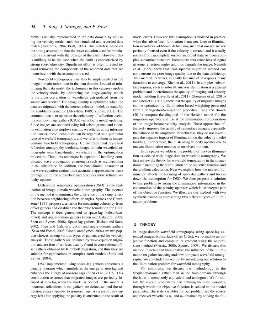
Figure 1. (a) The true model used to generate the data, (b) the migrated image, and (c) the angle-domain gathers obtained using the true model.
98 T. Yang, J. Shragge, and P. Sava
(a)
(b)
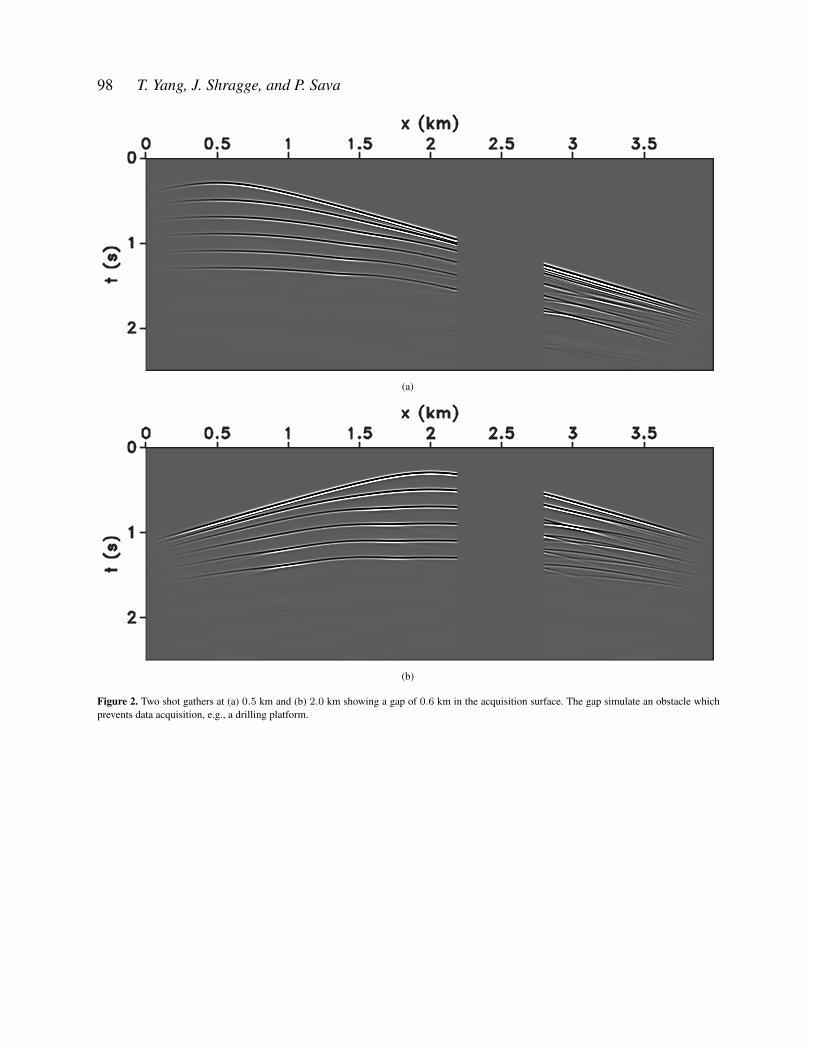
Figure 2. Two shot gathers at (a) 0.5 km and (b) 2.0 km showing a gap of 0.6 km in the acquisition surface. The gap simulate an obstacle whichprevents data acquisition, e.g., a drilling platform.
Wavefield tomography with illumination compensation 99
(a)
(b)
(c)
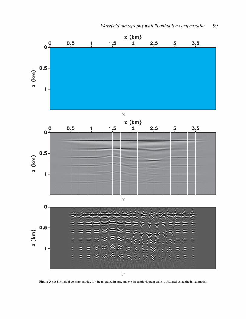
Figure 3. (a) The initial constant model, (b) the migrated image, and (c) the angle-domain gathers obtained using the initial model.
100 T. Yang, J. Shragge, and P. Sava
(a)
(b)
(c)
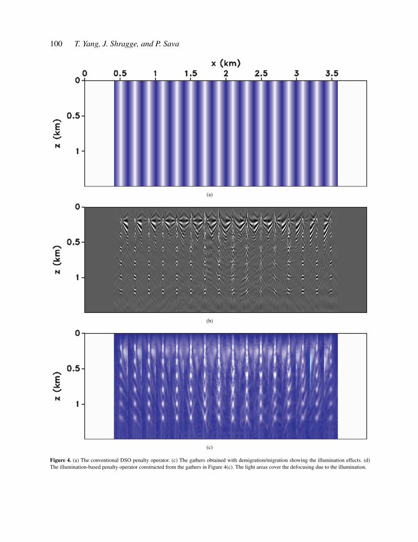
Figure 4. (a) The conventional DSO penalty operator. (c) The gathers obtained with demigration/migration showing the illumination effects. (d)The illumination-based penalty operator constructed from the gathers in Figure 4(c). The light areas cover the defocusing due to the illumination.
Wavefield tomography with illumination compensation 101
(a)
(b)
(c)
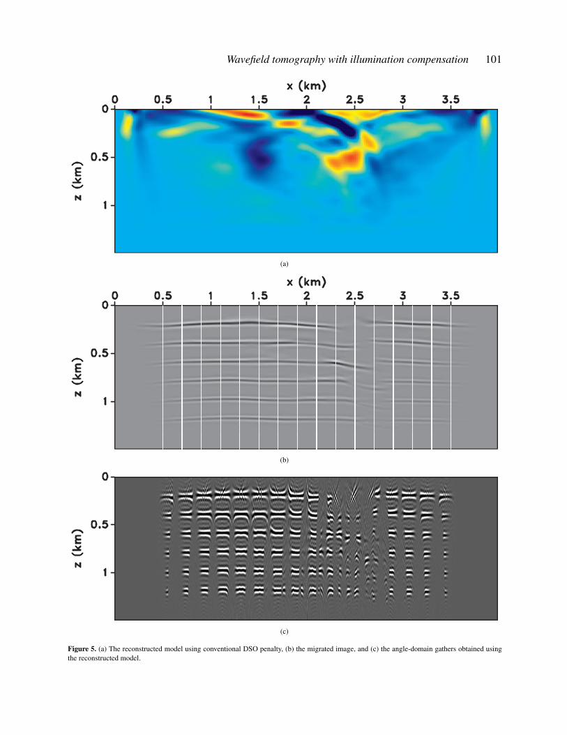
Figure 5. (a) The reconstructed model using conventional DSO penalty, (b) the migrated image, and (c) the angle-domain gathers obtained usingthe reconstructed model.
102 T. Yang, J. Shragge, and P. Sava
(a)
(b)
(c)
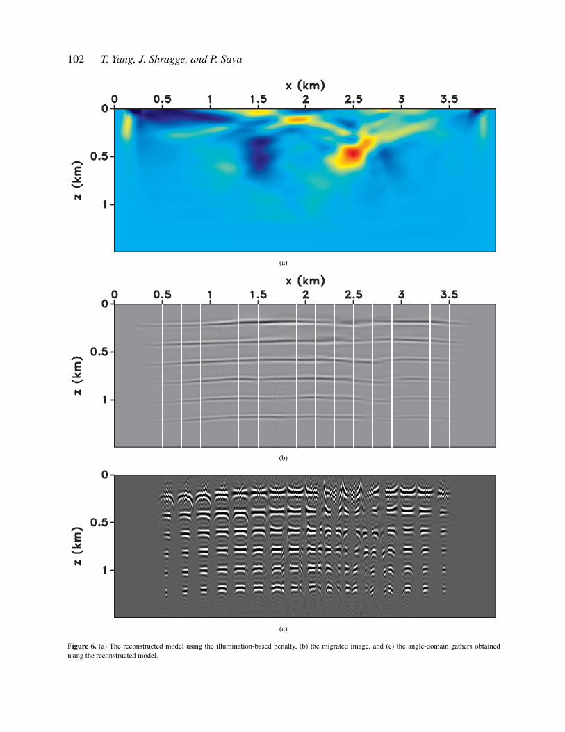
Figure 6. (a) The reconstructed model using the illumination-based penalty, (b) the migrated image, and (c) the angle-domain gathers obtainedusing the reconstructed model.
Wavefield tomography with illumination compensation 103
The velocity model for the first example is shown in Fig-ure 1(a). For five horizontal interfaces simulated as densitycontrasts, we generate the data at receivers distributed alongthe surface. Two shot gathers are shown in Figures 2(a) and2(b). The data are truncated from 2.2− 2.8 km to simulate anacquisition gap. The initial model is constant (Figures 3(a)).The migrated image and angle-domain gathers for the true andinitial models are shown in Figures 1(b)-1(c) and Figures 3(b)-3(c), respectively. Note that the angle gathers are displayed atselected locations corresponding to the vertical bars overlainin Figures 1(b) and 3(b). The migrated image for the initialmodel shows defocusing and crossing events caused by the in-correct model. The illumination gap due to the missing dataand the residual moveout caused by the wrong velocity can beobserved on the angle gathers shown in Figure 3(c).
For comparison with our method, we run the inversion us-ing conventional DSO penalty operator. Figure 9(a) plots thepenalty operators at the same selected locations shown in Fig-ure 1(b). The actual spacing of the gathers and penalty oper-ators are 0.2 km. Since the conventional penalty is laterallyinvariant, the figure consists of the same operators duplicatedat different lateral position. The inverted model after 30 non-linear iterations is plotted in Figure 5(a), and the correspond-ing migrated image and angle gathers are shown in Figure 5(b)and 5(c). The reconstruction of the model is not satisfactory,especially for the anomaly under the acquisition gap. Also, themodel contains many artifacts as the consequence of the in-complete data. As a result, the reduced quality of the imageobtained with the inverted model is not surprising. Althoughthe reflections on the left of the image are quite continuousand flat, those on the right, especially under the acquisitiongap, are not flat and are even discontinuous. This result clearlyshows the negative impact of the poor illumination on image-domain wavefield tomography.
To show the defocusing due to illumination effects in thegathers, we construct the space-lag gathers with the currentimage in Figure 3(b) at zero-lag as the reference image gath-ers. We apply the demigration/migration workflow from equa-tion 15 to the reference gathers. The result, as shown in Fig-ure 4(b), characterizes the illumination effects given the ve-locity model and acquisition setup. Most reflection energy isfocused, thus indicating good illumination, but we can still ob-serve defocusing as the consequence of incomplete data in thearea under the acquisition gap. The illumination-based penaltyoperator is constructed from the gathers in Figure 4(b) usingequation 16, as plotted in Figure 4(c). We can observe that theareas in light color coincide with the focused energy at zerolag and defocusing away from zero lag in Figure 4(b). Thus,the penalty operator does not emphasize the defocusing dueto the uneven illumination and highlights only the defocusingdue to velocity errors.
Using the new penalty operator, we update the model un-der the same conditions as in the example using DSO, Fig-ure 6(a). Compared with the result in Figure 5(a), the resultobtained with the new penalty is cleaner and contains fewerartifacts. Also, the anomaly under the acquisition gap is moreaccurately reconstructed and closer to the true model. Be-
cause of the improved model, the images are also improved, asseen in Figure 6(b). The reflections under the acquisition gapare more continuous and flat than the image in Figure 5(b).In addition, one can observe from the angle gathers in Fig-ure 6(c) that more events appear in the area under the acquisi-tion gap and overall reflections are flatter, which indicates animproved signal-to-noise ratio rising from the more accuratereconstructed model.
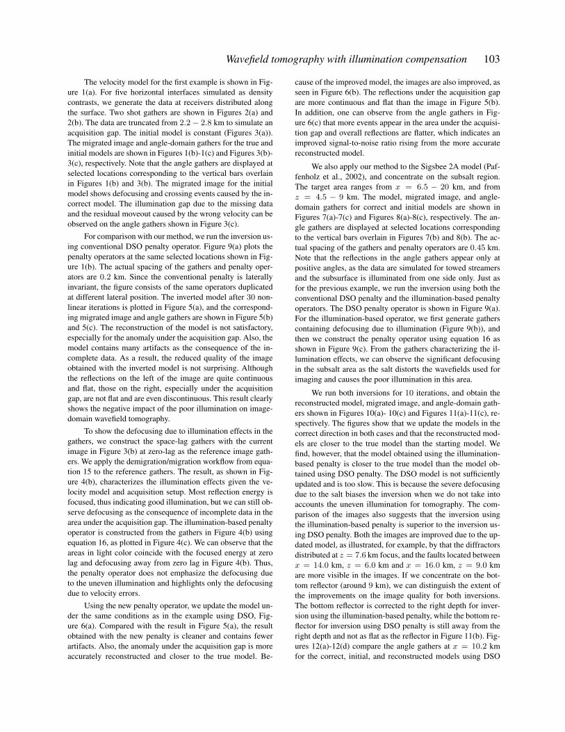
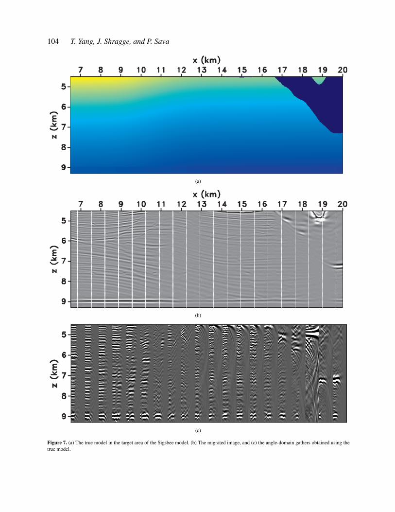
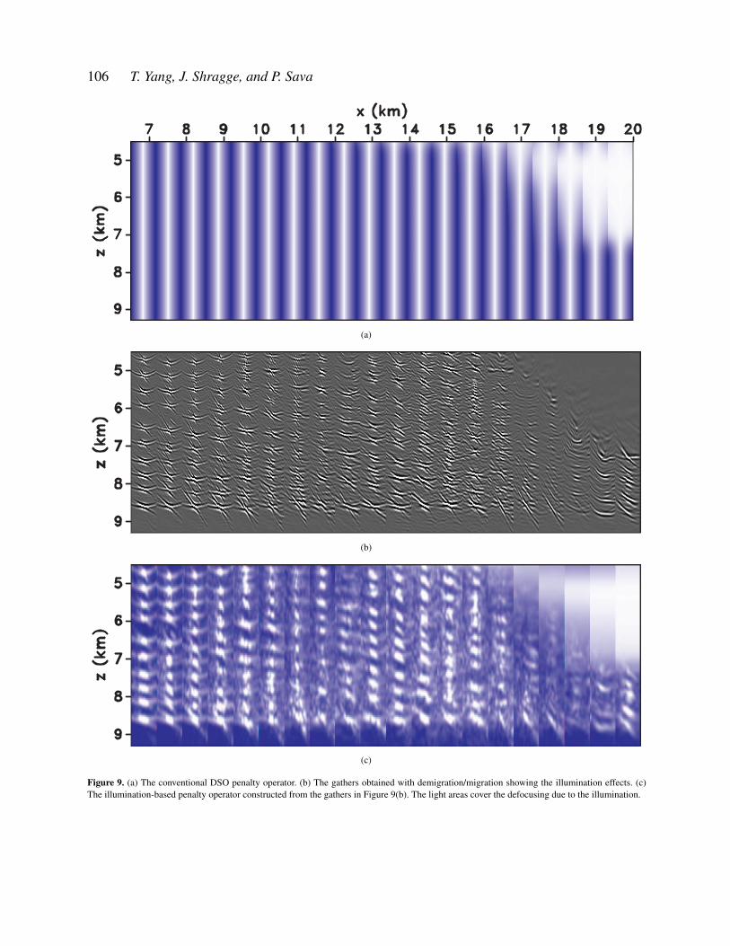
We also apply our method to the Sigsbee 2A model (Paf-fenholz et al., 2002), and concentrate on the subsalt region.The target area ranges from x = 6.5 − 20 km, and fromz = 4.5 − 9 km. The model, migrated image, and angle-domain gathers for correct and initial models are shown inFigures 7(a)-7(c) and Figures 8(a)-8(c), respectively. The an-gle gathers are displayed at selected locations correspondingto the vertical bars overlain in Figures 7(b) and 8(b). The ac-tual spacing of the gathers and penalty operators are 0.45 km.Note that the reflections in the angle gathers appear only atpositive angles, as the data are simulated for towed streamersand the subsurface is illuminated from one side only. Just asfor the previous example, we run the inversion using both theconventional DSO penalty and the illumination-based penaltyoperators. The DSO penalty operator is shown in Figure 9(a).For the illumination-based operator, we first generate gatherscontaining defocusing due to illumination (Figure 9(b)), andthen we construct the penalty operator using equation 16 asshown in Figure 9(c). From the gathers characterizing the il-lumination effects, we can observe the significant defocusingin the subsalt area as the salt distorts the wavefields used forimaging and causes the poor illumination in this area.
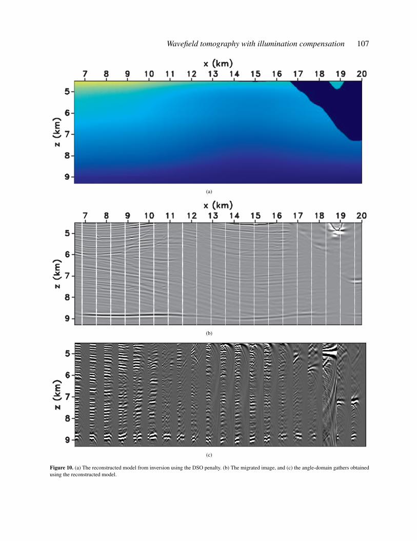
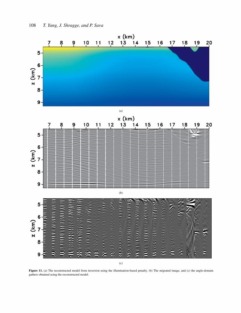
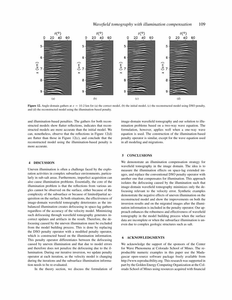
We run both inversions for 10 iterations, and obtain thereconstructed model, migrated image, and angle-domain gath-ers shown in Figures 10(a)- 10(c) and Figures 11(a)-11(c), re-spectively. The figures show that we update the models in thecorrect direction in both cases and that the reconstructed mod-els are closer to the true model than the starting model. Wefind, however, that the model obtained using the illumination-based penalty is closer to the true model than the model ob-tained using DSO penalty. The DSO model is not sufficientlyupdated and is too slow. This is because the severe defocusingdue to the salt biases the inversion when we do not take intoaccounts the uneven illumination for tomography. The com-parison of the images also suggests that the inversion usingthe illumination-based penalty is superior to the inversion us-ing DSO penalty. Both the images are improved due to the up-dated model, as illustrated, for example, by that the diffractorsdistributed at z = 7.6 km focus, and the faults located betweenx = 14.0 km, z = 6.0 km and x = 16.0 km, z = 9.0 kmare more visible in the images. If we concentrate on the bot-tom reflector (around 9 km), we can distinguish the extent ofthe improvements on the image quality for both inversions.The bottom reflector is corrected to the right depth for inver-sion using the illumination-based penalty, while the bottom re-flector for inversion using DSO penalty is still away from theright depth and not as flat as the reflector in Figure 11(b). Fig-ures 12(a)-12(d) compare the angle gathers at x = 10.2 kmfor the correct, initial, and reconstructed models using DSO
104 T. Yang, J. Shragge, and P. Sava
(a)
(b)
(c)
Figure 7. (a) The true model in the target area of the Sigsbee model. (b) The migrated image, and (c) the angle-domain gathers obtained using thetrue model.
Wavefield tomography with illumination compensation 105
(a)
(b)
(c)
Figure 8. (a) The initial model obtained by scaling the true model. (b) The migrated image, and (c) the angle-domain gathers obtained using theinitial model.
106 T. Yang, J. Shragge, and P. Sava
(a)
(b)
(c)
Figure 9. (a) The conventional DSO penalty operator. (b) The gathers obtained with demigration/migration showing the illumination effects. (c)The illumination-based penalty operator constructed from the gathers in Figure 9(b). The light areas cover the defocusing due to the illumination.
Wavefield tomography with illumination compensation 107
(a)
(b)
(c)
Figure 10. (a) The reconstructed model from inversion using the DSO penalty. (b) The migrated image, and (c) the angle-domain gathers obtainedusing the reconstructed model.
108 T. Yang, J. Shragge, and P. Sava
(a)
(b)
(c)
Figure 11. (a) The reconstructed model from inversion using the illumination-based penalty. (b) The migrated image, and (c) the angle-domaingathers obtained using the reconstructed model.
Wavefield tomography with illumination compensation 109
(a) (b) (c) (d)
Figure 12. Angle-domain gathers at x = 10.2 km for (a) the correct model, (b) the initial model, (c) the reconstructed model using DSO penalty,and (d) the reconstructed model using the illumination-based penalty.
and illumination-based penalties. The gathers for both recon-structed models show flatter reflections, indicates that recon-structed models are more accurate than the initial model. Wecan, nonetheless, observe that the reflections in Figure 12(d)are flatter than those in Figure 12(c), and conclude that thereconstructed model using the illumination-based penalty ismore accurate.
4 DISCUSSION
Uneven illumination is often a challenge faced by the explo-ration activities in complex subsurface environments, particu-larly in sub-salt areas. Furthermore, imperfect acquisition canalso cause illumination problems. Essentially, the core of theillumination problem is that the reflections from various an-gles cannot be observed on the surface, either because of thecomplexity of the subsurface or because of limited/partial ac-quisition on the surface. In both situations, the effectiveness ofimage-domain wavefield tomography deteriorates as the im-balanced illumination creates defocusing in space-lag gathersregardless of the accuracy of the velocity model. Minimizingsuch defocusing through wavefield tomography generates in-correct updates and artifacts in the result. Therefore, the de-focusing caused by the uneven illumination must be excludedfrom the model building process. This is done by replacingthe DSO penalty operator with a modified penalty operator,which is constructed based on the illumination information.This penalty operator differentiates between the defocusingcaused by uneven illumination and that due to model errorsand therefore does not penalize the defocusing due to the il-lumination. During our iterative inversion, we update penaltyoperator at each iteration, as the velocity model is changingduring the iterations and the subsurface illumination informa-tion needs to be re-evaluated.
In the theory section, we discuss the formulation of
image-domain wavefield tomography and our solution to illu-mination problems based on a two-way wave equation. Theformulation, however, applies well when a one-way waveequation is used. The construction of the illumination-basedpenalty operator is similar, except for the wave equation usedin all modeling and migrations.
5 CONCLUSIONS
We demonstrate an illumination compensation strategy forwavefield tomography in the image domain. The idea is tomeasure the illumination effects on space-lag extended im-ages, and replace the conventional DSO penalty operator withanother one that compensates for illumination. This approachisolates the defocusing caused by the illumination such thatimage-domain wavefield tomography minimizes only the de-focusing relevant to the velocity error. Synthetic examplesdemonstrate the negative effects of uneven illumination on thereconstructed model and show the improvements on both theinversion results and on the migrated images after the illumi-nation information is included in the penalty operator. Our ap-proach enhances the robustness and effectiveness of wavefieldtomography in the model building process when the surfacedata are incomplete or when the subsurface illumination is un-even due to complex geologic structures such as salt.
6 ACKNOWLEDGMENTS
We acknowledge the support of the sponsors of the Centerfor Wave Phenomena at Colorado School of Mines. The re-producible numeric examples in this paper use the Mada-gascar open-source software package freely available fromhttp://www.reproducibility.org. This research was supported inpart by the Golden Energy Computing Organization at the Col-orado School of Mines using resources acquired with financial
110 T. Yang, J. Shragge, and P. Sava
assistance from the National Science Foundation and the Na-tional Renewable Energy Laboratory.
REFERENCES
Al-Yahya, K., 1989, Velocity analysis by iterative profile mi-gration: Geophysics, 54, 718–729.
Biondi, B., and W. Symes, 2004, Angle-domain common-image gathers for migration velocity analysis by wavefield-continuation imaging: Geophysics, 69, 1283–1298.
Etgen, J., S. H. Gray, and Y. Zhang, 2009, An overview ofdepth imaging in exploration geophysics: Geophysics, 74,WCA5–WCA17.
Gherasim, M., U. Albertin, B. Nolte, and O. Askim, 2010,Wave-equation angle-based illumination weighting for op-timized subsalt imaging: Presented at the 80th Annual In-ternational Meeting, SEG, Expanded Abstracts.
Gray, S. H., J. Etgen, J. Dellinger, and D. Whitmore, 2001,Seismic migration problems and solutions: Geophysics, 66,1622–1640.
Guitton, A., 2004, Amplitude and kinematic corrections ofmigrated images for nonunitary imaging operators: Geo-physics, 69, 1017–1024.
Knyazev, A. V., and I. Lashuk, 2007, Steepest descent andconjugate gradient methods with variable preconditioning:Matrix Analysis and Applications, 29, 1267–1280.
Leveille, J. P., I. F. Jones, Z. Z. Zhou, B. Wang, and F. Liu,2011, Subsalt imaging for exploration, production, and de-velopment: A review: Geophysics, 76, WB3–WB20.
Nemeth, T., C. Wu, and G. T. Schuster, 1999, Least-squaremigration of incomplete reflection data: Geophysics, 64,208–221.
Paffenholz, J., B. McLain, J. Zaske, and P. Keliher, 2002,Subsalt multiple attenuation and imaging: Observationsfrom the sigsbee 2b synthetic dataset: 72nd Annual Inter-national Meeting, SEG, Expanded Abstracts, 2122–2125.
Plessix, R.-E., 2006, A review of the adjoint state methodfor computing the gradient of a functional with geophysicalapplications: Geophysical Journal International, 167, 495–503.
——–, 2009, Three-dimensional frequency-domain full-waveform inversion with an iterative solver: Geophysics,74, WCC53–WCC61.
Pratt, R. G., 1999, Seismic waveform inversion in the fre-quency domain, Part 1: Theory and verification in a physicalscale model: Geophysics, 64, 888–901.
Rickett, J., and P. Sava, 2002, Offset and angle-domain com-mon image-point gathers for shot-profile migration: Geo-physics, 67, 883–889.
Sava, P., and S. Fomel, 2003, Angle-domain common imagegathers by wavefield continuation methods: Geophysics, 68,1065–1074.
Shen, H., S. Mothi, and U. Albertin, 2011, Improving subsaltimaging with illumination-based weighting of rtm 3d anglegathers: Presented at the 81th Annual International Meet-ing, SEG, Expanded Abstracts.
Shen, P., and H. Calandra, 2005, One-way waveform in-version within the framework of adjoint state differentialmigration: 75th Annual International Meeting, SEG, Ex-panded Abstracts, 1709–1712.
Shen, P., C. Stolk, and W. Symes, 2003, Automatic veloc-ity analysis by differential semblance optimization: 73thAnnual International Meeting, SEG, Expanded Abstracts,2132–2135.
Shen, P., and W. W. Symes, 2008, Automatic velocity analy-sis via shot profile migration: Geophysics, 73, VE49–VE59.
Sirgue, L., and R. Pratt, 2004, Efficient waveform inversionand imaging: A strategy for selecting temporal frequencies:Geophysics, 69, 231–248.
Stolk, C. C., and W. W. Symes, 2004, Kinematic artifacts inprestack depth migration: Geophysics, 69, 562–575.
Symes, W., 2009, Migration velocity analysis and waveforminversion: Geophysical Prospecting, 56, 765–790.
Symes, W. W., 2008, Migration velocity analysis and wave-form inversion: Geophysical Prospecting, 56, 765–790.
Symes, W. W., and J. J. Carazzone, 1991, Velocity inver-sion by differential semblance optimization: Geophysics,56, 654–663.
Tang, Y., and B. Biondi, 2011, Target-oriented wavefieldtomography using synthesized born data: Geophysics, 76,WB191–WB207.
Tarantola, A., 1984, Inversion of seismic reflection data inthe acoustic approximation: Geophysics, 49, 1259–1266.
Vigh, D., and E. W. Starr, 2008, 3D prestack plane-wave, full-waveform inversion: Geophysics, 73, VE135–VE144.
Virieux, J., and S. Operto, 2009, An overview of full-waveform inversion in exploration geophysics: Geophysics,74, WCC1–WCC26.
Woodward, M., D. Nichols, O. Zdraveva, P. Whitfield, andT. Johns, 2008, A decade of tomography: Geophysics, 73,VE5–VE11.
Woodward, M. J., 1992, Wave-equation tomography: Geo-physics, 57, 15–26.
Yang, T., and P. Sava, 2010, Moveout analysis of wave-equation extended images: Geophysics, 75, 151–161.
Yilmaz, O., 2001, Seismic Data Analysis (2nd edition): So-ciety of Exploration Geophysicists.
Yu, J., and T. Schuster, 2003, Migration deconvolution vs.least squares migration: Presented at the 74th Annual Inter-national Meeting, SEG, Expanded Abstracts.


![Illumination-Aware Age Progressionnovel illumination-aware age progression technique, lever-aging illumination modeling results [1,31], that properly account for scene illumination](https://img.pdfslide.net/doc/110x75/5e72745a0ac7de5cbf4199be/illumination-aware-age-progression-novel-illumination-aware-age-progression-technique.jpg)