Embed Size (px)
Citation preview

LN-9 GMA Troubleshooting Guide
Troubleshooting Guide
IM355-TSNovember, 2001
Safety Depends on YouLincoln arc welding and cutting
equipment is designed and built
with safety in mind. However, your
overall safety can be increased by
proper installation ... and thought-
ful operation on your part. DONOT INSTALL, OPERATE ORREPAIR THIS EQUIPMENTWITHOUT READING THIS MAN-UAL AND THE SAFETY PRE-CAUTIONS CONTAINEDTHROUGHOUT. And, most
importantly, think before you act
and be careful.
• Sales and Service through Subsidiaries and Distributors Worldwide •
Cleveland, Ohio 44117-1199 U.S.A. TEL: 216.481.8100 FAX: 216.486.1751 WEB SITE: www.lincolnelectric.com
• World's Leader in Welding and Cutting Products •
Copyright © 2001 Lincoln Global Inc.
This manual covers equipment which is no longer in production by The Lincoln Electric Co. Speci�cations and availability of optional features may have changed.

TS-1 TS-1
LN-9 GMA Wire Feeder
Troubleshooting Guide....................................................................................................................
How to Use Troubleshooting Guide ....................................................................................TS-2
PC Board Troubleshooting Procedures...............................................................................TS-3
Troubleshooting Guide...........................................................................................TS-4 - TS-23
Test ProceduresT1 Transformer Test ....................................................................................................TS-24T2 Transformer Test ....................................................................................................TS-27Wire Drive Motor Test .................................................................................................TS-31Hall Effect Test and Alignment....................................................................................TS-34Voltmeter Accuracy Test .............................................................................................TS-38Meter Circuit Accuracy Test........................................................................................TS-41Wire Speed Accuracy Test..........................................................................................TS-46Out of Voltage Range Shut Down Test .......................................................................TS-48General Power Supply Tests.......................................................................................TS-51
TABLE OF CONTENTSTROUBLESHOOTING GUIDE
NOTE
This Troubleshooting section is specific to the LN-9 GMA. However, much of this informationmay apply to the LN-9 F GMA model with slightadaptation. Refer to LN-9F GMA Wiring Diagram.

HOW TO USE TROUBLESHOOTING GUIDE
Service and repair should be performed by only Lincoln Electric Factory Trained Personnel.Unauthorized repairs performed on this equipment may result in danger to the technician and machineoperator and will invalidate your factory warranty. For your safety and to avoid Electrical Shock, pleaseobserve all safety notes and precautions detailed throughout this manual.
TROUBLESHOOTINGTS-2 TS-2
LN-9 GMA Wire Feeder
CAUTION
This Troubleshooting Guide is provided to helpyou locate and repair possible machine malfunc-tions. Simply follow the three-step procedurelisted below.
Step 1. LOCATE PROBLEM (SYMPTOM). Lookunder the column labeled “PROBLEM (SYMP-TOMS). This column describes possible symp-toms that the machine may exhibit. Find the list-ing that best describes the symptom that themachine is exhibiting. Symptoms are groupedinto main categories: Function Problems,Feeding Problems, Welding Problems, MeterProblems, and Starting Problems.
Step 2. PERFORM EXTERNAL TESTS. Thesecond column, labeled “POSSIBLE AREAS OFMISADJUSTMENT(S)”, lists the obvious externalpossibilities that may contribute to the machinesymptom. Perform these tests/checks in theorder listed. In general, these tests can be con-ducted without removing the case wrap-aroundcover.
Step 3. PERFORM COMPONENT TESTS. Thelast column, labeled “Recommended Course ofAction” lists the most likely components that mayhave failed in your machine. It also specifies theappropriate test procedure to verify that the sub-ject component is either good or bad. If there area number of possible components, check thecomponents in the order listed to eliminate onepossibility at a time until you locate the cause ofyour problem.
All of the referenced test procedures referred to inthe Troubleshooting Guide are described in detailat the end of this chapter. Refer to theTroubleshooting and Repair Table of Contents tolocate each specific Test Procedure. All of thereferred to test points, components, terminalstrips, etc., can be found on the referenced elec-trical wiring diagrams and schematics. Refer tothe Electrical Diagrams Section Table of Contentsto locate the appropriate diagram.
WARNING
If for any reason you do not understand the test procedures or are unable to perform the test/repairssafely, contact the Lincoln Electric Service Department for electrical troubleshooting assistance beforeyou proceed. Call 1-888-935-3877.

ELECTRIC SHOCK can kill.
Have an electrician install and servicethis equipment. Turn the machine OFFbefore working on equipment. Do nottouch electrically hot parts.
Sometimes machine failures appear to be due to PCboard failures. These problems can sometimes betraced to poor electrical connections. To avoid prob-lems when troubleshooting and replacing PC boards,please use the following procedure:
1. Determine to the best of your technical ability thatthe PC board is the most likely component caus-ing the failure symptom.
2. Check for loose connections at the PC board toassure that the PC board is properly connected.
3. If the problem persists, replace the suspect PCboard using standard practices to avoid staticelectrical damage and electrical shock. Read thewarning inside the static resistant bag and performthe following procedures:
PC Board can be damaged by static electricity.
• Remove your body’s static chargebefore opening the static-shield-ing bag. Wear an anti-static wriststrap. For safety, use a 1 Megohm resistive cord con nected to agrounded part of the equipmentframe.
• If you don’t have a wrist strap,touch an unpainted, grounded,part of the equipment frame.Keep touching the frame to pre-vent static build-up. Be sure notto touch any electrically live partsat the same time.
• Tools which come in contact with the PC Board mustbe either conductive, anti-static or static-dissipative.
• Remove the PC Board from the static-shielding bagand place it directly into the equipment. Don’t setthe PC Board on or near paper, plastic or cloth whichcould have a static charge. If the PC Board can’t beinstalled immediately, put it back in the static-shielding bag.
• If the PC Board uses protective shorting jumpers,don’t remove them until installation is complete.
• If you return a PC Board to The Lincoln ElectricCompany for credit, it must be in the static-shieldingbag. This will prevent further damage and allowproper failure analysis.
4. Test the machine to determine if the failure symp-tom has been corrected by the replacement PCboard.
NOTE: Allow the machine to heat up so that all elec-trical components can reach their operatingtemperature.
5. Remove the replacement PC board and substituteit with the original PC board to recreate the originalproblem.
a. If the original problem does not reappearby substituting the original board, then thePC board was not the problem. Continueto look for bad connections in the controlwiring harness, junction blocks, and termi-nal strips.
b. If the original problem is recreated by thesubstitution of the original board, then thePC board was the problem. Reinstall thereplacement PC board and test themachine.
6. Always indicate that this procedure was followedwhen warranty reports are to be submitted.
NOTE: Following this procedure and writing on thewarranty report, “INSTALLED AND SWITCHEDPC BOARDS TO VERIFY PROBLEM,” will helpavoid denial of legitimate PC board warrantyclaims.
TROUBLESHOOTINGTS-3 TS-3
LN-9 GMA Wire Feeder
PC BOARD TROUBLESHOOTING PROCEDURES
WARNING
ATTENTIONStatic-SensitiveDevicesHandle only atStatic-SafeWorkstations
ReusableContainerDo Not Destroy

TROUBLESHOOTINGTS-4 TS-4
LN-9 GMA Wire Feeder
Observe Safety Guidelines TROUBLESHOOTING GUIDEdetailed in the beginning of this manual.
CAUTIONIf for any reason you do not understand the test procedures or are unable to perform the test/repairs safely, con-tact the Lincoln Electric Service Department for electrical troubleshooting assistance before you proceed. Call1-888-935-3877.
PROBLEMS(SYMPTOMS)
POSSIBLE AREAS OFMISADJUSTMENT(S)
RECOMMENDEDCOURSE OF ACTION
FUNCTION PROBLEMS
No wire feed when gun trigger isactivated. The digital meter doesNOT light. The drive rolls do notturn.
1. Make sure 115VAC is beingapplied to the LN-9 GMA at theinput connector. Pin "C" is lead#31 and pin "D" is lead #32.
2. Check the 3 amp circuit break-er. Reset if tripped.
3. The F101 4/10 amp slow blowfuse, located on the power PCboard, may be blown.
1. Check for loose or faulty leadconnections between the inputconnector, the T1 transformer,and the power PC board.
2. The T1 transformer may befaulty. Perform the T1 Trans -former Test.

TROUBLESHOOTING & REPAIRTS-5 TS-5
LN-9 GMA Wire Feeder
TROUBLESHOOTING GUIDE Observe Safety Guidelinesdetailed in the beginning of this manual.
CAUTIONIf for any reason you do not understand the test procedures or are unable to perform the test/repairs safely, con-tact the Lincoln Electric Service Department for electrical troubleshooting assistance before you proceed. Call 1-888-935-3877.
PROBLEMS(SYMPTOMS)
POSSIBLE AREAS OFMISADJUSTMENT(S)
RECOMMENDEDCOURSE OF ACTION
FUNCTION PROBLEMSNo wire feed when gun trigger isactivated. The drive rolls do notturn. The digital meter does lightbut reads only SET voltage andwire speed values.
1. The Ground Lead Protectormay have tripped. Reset andclear possible fault betweenelectrode circuit and feederframe.
2. The gun trigger may be faulty.
1. The 1CR relay on the power PCboard may be faulty. Check orreplace.
2. Check resistor R1. Normalresistance is 2 ohms.
3. Perform the TriggerTransformer T2 Test.
4. Perform the Trigger BoardTest.
5. Perform the Wire Drive MotorTest.
6. If the wire drive motor is OK, thepower PC board or the controlboard may be faulty.

TROUBLESHOOTINGTS-6 TS-6
LN-9 GMA Wire Feeder
Observe Safety Guidelines TROUBLESHOOTING GUIDEdetailed in the beginning of this manual.
CAUTIONIf for any reason you do not understand the test procedures or are unable to perform the test/repairs safely, con-tact the Lincoln Electric Service Department for electrical troubleshooting assistance before you proceed. Call1-888-935-3877.
PROBLEMS(SYMPTOMS)
POSSIBLE AREAS OFMISADJUSTMENT(S)
RECOMMENDEDCOURSE OF ACTION
FUNCTION PROBLEMS
The wire feed “coasts” when thegun trigger is released.
1. Make sure the gun trigger is not“sticking.”
1. The relay 1CR may be faulty.Replace.
The gas solenoid does not activatewhen the gun trigger is closed.The wire feeds and arc voltage ispresent.
1. If a K418 GMA Timer Kit or aK419 Burnback Timer Kit isinstalled, disconnect it andreplace it with the jumper plug.If the problem is resolved, theK418 or K419 is faulty.
1. With the gun trigger closed,check for 115VAC at the powerPC board terminals #7A to#32A.
a. If the 115VAC is present,the solenoid may be faulty.Replace.
b. If the 115VAC is NOT pre-sent at terminals #7 and#32, the relay CR1 on thepower PC board may befaulty. Replace.
The gas solenoid stays open afterthe gun trigger switch is released.
1. The gas solenoid may be stuckin the open position.
1. With the gun trigger NOTclosed, check for 115VAC atthe power PC board terminals#7 to #32A.
a. If the 115VAC is present,the relay CR1 may bedefective.
b. If the 115VAC is NOT pre-sent, the gas solenoid maybe defective.

TROUBLESHOOTINGTS-7 TS-7
LN-9 GMA Wire Feeder
TROUBLESHOOTING GUIDE Observe Safety Guidelinesdetailed in the beginning of this manual.
CAUTIONIf for any reason you do not understand the test procedures or are unable to perform the test/repairs safely, con-tact the Lincoln Electric Service Department for electrical troubleshooting assistance before you proceed. Call 1-888-935-3877.
PROBLEMS(SYMPTOMS)
POSSIBLE AREAS OFMISADJUSTMENT(S)
RECOMMENDEDCOURSE OF ACTION
FUNCTION PROBLEMS
The wire feeds when the gun trig-ger is activated, but there is no arcvoltage.
1. Make sure the interlock switchis in a "Wire Hot" position.
2. Check the welding cables forloose or faulty connections.
3. Put a jumper wire from #2 to #4on the power source terminalstrip. (Machines with 14 pinamphenols: pin C to pin D.) Ifthe arc voltage is not present atthe output terminals, the powersource is faulty. If the arc volt-age IS present, the problem isin the wire feeder or controlcable.
4. Check the continuity of leads#2 and #4 through the controlcable. Replace if "open."
1. The 1CR relay, located on thepower PC board, may be faulty.Check or replace.
2. If a burnback kit is installed,remove and install the jumperplug. If the problem is solved,the burnback kit is faulty.
3. Check the #2 and #4 leads inthe LN-9 GMA wiring harnessfor loose or faulty connections.See the Wiring Diagram.

TROUBLESHOOTINGTS-8 TS-8
LN-9 GMA Wire Feeder
Observe Safety Guidelines TROUBLESHOOTING GUIDEdetailed in the beginning of this manual.
CAUTIONIf for any reason you do not understand the test procedures or are unable to perform the test/repairs safely, con-tact the Lincoln Electric Service Department for electrical troubleshooting assistance before you proceed. Call 1-888-935-3877.
PROBLEMS(SYMPTOMS)
POSSIBLE AREAS OFMISADJUSTMENT(S)
RECOMMENDEDCOURSE OF ACTION
FUNCTION PROBLEMS
The SET speed is adjustable andsteady. The actual speed is uncon-trollable. The meter displays theactual speed correctly or reads"EEE."
1. Contact your local LincolnAuthorized Field ServiceFacility.
1. While the motor is running,carefully unplug the 15 pinmolex plug from the control PCboard.
If the motor continues to run,the power PC board may befaulty. Replace.
If the motor stops, the controlPC board may be faulty.Replace.
2. Perform the Wire Drive MotorTest.
The SET speed is adjustable andsteady. The actual speed readingis incorrect and/or erratic.
1. Check for loose or faulty con-nections on leads #510, #525,and #555 between the halleffect module and the controlPC board.
1. Perform the Hall EffectModule AlignmentProcedure.
2. Perform the Hall Effect Feed -back Test.
3. If the Hall Effect FeedbackTest is OK, the control PCboard may be faulty. Replace.

TROUBLESHOOTING & REPAIRTS-9 TS-9
LN-9 GMA Wire Feeder
TROUBLESHOOTING GUIDE Observe Safety Guidelinesdetailed in the beginning of this manual.
CAUTIONIf for any reason you do not understand the test procedures or are unable to perform the test/repairs safely, con-tact the Lincoln Electric Service Department for electrical troubleshooting assistance before you proceed. Call1-888-935-3877.
PROBLEMS(SYMPTOMS)
POSSIBLE AREAS OFMISADJUSTMENT(S)
RECOMMENDEDCOURSE OF ACTION
FUNCTION PROBLEMS
The SET speed is erratic or notadjustable over entire range ofcontrol. The actual speed is alsoerratic like the SET speed.
1. Check for loose or faulty con-nections on leads #631, #632,and #633 between the speedcontrol potentiometer (R2) andthe control PC board.
1. Remove power to the LN-9GMA and disconnect the plugto the control PC board. Checkthe resistance of the speedcontrol potentiometer (R2).When measured from the wiper(lead #632) to lead #633, theresistance should vary smooth-ly from 0 to 10,000 ohms whenthe shaft is rotated. See theWiring Diagram.
2. The control PC board may befaulty. Replace.
The wire continues to feed with thegun trigger open, and the wire iselectrically "hot." The interlockswitch is in the "OFF" position.
1. Disconnect the gun triggercable. If the problem isresolved, the gun trigger orcable is faulty. Repair orreplace.
1. Disconnect lead #530 from thetrigger PC board. See theWiring Diagram. If the problemis resolved, the trigger board isfaulty. Replace.
2. Relay 1CR may be stuckclosed. Check or replace.
3. The power PC board may befaulty. Replace.

TROUBLESHOOTING & REPAIRTS-10 TS-10
LN-9 GMA Wire Feeder
Observe Safety Guidelines TROUBLESHOOTING GUIDEdetailed in the beginning of this manual.
CAUTIONIf for any reason you do not understand the test procedures or are unable to perform the test/repairs safely, con-tact the Lincoln Electric Service Department for electrical troubleshooting assistance before you proceed. Call1-888-935-3877.
PROBLEMS(SYMPTOMS)
POSSIBLE AREAS OFMISADJUSTMENT(S)
RECOMMENDEDCOURSE OF ACTION
TRIGGER INTERLOCK FUNCTION PROBLEMS
The wire feeds when the interlockswitch is in the "ON" position. Nowelding or gun trigger activation.
1. Check to see if the reed switch2CR is stuck closed.
1. Check the 2CR reed switch forsticking and associated leads(#529 and #628) for shorts.
2. The power PC board may befaulty. Replace.
With the interlock switch in the"ON" position, the wire feed stopswhen the gun trigger is released.
1. Check leads #529 and #628 forloose or faulty connectionsbetween the 2CR reed switchand the power PC board.
1. The 2CR reed switch may befaulty. Check to see if it closeswhen welding.
2. Check the continuity (zeroohms) of leads #529 and #628from the 2CR reed switch to thepower PC board. Also checkcontinuity of leads #530 and#522 from the power PC boardto the interlock switch. See theWiring Diagram.
3. Check the interlock switch forproper operation.
4. The power PC board may befaulty. Replace.

TROUBLESHOOTINGTS-11 TS-11
LN-9 GMA Wire Feeder
TROUBLESHOOTING GUIDE Observe Safety Guidelinesdetailed in the beginning of this manual.
CAUTIONIf for any reason you do not understand the test procedures or are unable to perform the test/repairs safely, con-tact the Lincoln Electric Service Department for electrical troubleshooting assistance before you proceed. Call1-888-935-3877.
PROBLEMS(SYMPTOMS)
POSSIBLE AREAS OFMISADJUSTMENT(S)
RECOMMENDEDCOURSE OF ACTION
FUNCTION PROBLEMS
The SET voltage is erratic or notadjustable over the entire range ofcontrol. The actual voltage is alsoerratic like the SET voltage.
1. Check for loose or faulty con-nections on leads #634, #635,and #636 between the voltagecontrol potentiometer (R3) andthe voltage PC board.
1. Remove power to the LN-9GMA and disconnect Plug J9from the voltage PC board.Check the resistance of thevoltage control potentiometer(R3). When measured from thewiper (lead #635) to lead #634,the resistance should varysmoothly from 0 to 10,000ohms when the shaft is rotated.
2. The voltage PC board may befaulty. Replace.
The field fuse (F101), located onthe power PC board, repeatedlyfails.
1. Make sure the replacementfuse is a 4/10 amp slow blowtype fuse.
1. Perform the T1 TransformerTest.
2. Disconnect the meter PCboard. If the problem isresolved, the meter PC boardmay be faulty.
3. The power PC board may befaulty. Replace.

TS-12 TS-12
LN-9 GMA Wire Feeder
TROUBLESHOOTING
TROUBLESHOOTING GUIDE Observe Safety Guidelinesdetailed in the beginning of this manual.
CAUTIONIf for any reason you do not understand the test procedures or are unable to perform the test/repairs safely, con-tact the Lincoln Electric Service Department for electrical troubleshooting assistance before you proceed. Call1-888-935-3877.
PROBLEMS(SYMPTOMS)
POSSIBLE AREAS OFMISADJUSTMENT(S)
RECOMMENDEDCOURSE OF ACTION
FUNCTION PROBLEMS
Circuit breaker (3 amp) repeatedlytrips when the gun trigger is acti-vated.
1. Check or replace gun triggerand leads. Make sure the trig-ger leads are not shorted to theelectrode or work cables.
1. Disconnect lead #500 from thetrigger PC board. If the breakerstill trips when the gun trigger isactivated, the trigger PC boardmay be faulty. Replace
2. Disconnect any accessory thatmay be connected to terminals#7 and #32A. See the WiringDiagram. If the problem isresolved, the accessory may befaulty. Replace.
3. Perform the Wire Drive MotorTest.
4. The power PC board may befaulty. Replace.
Circuit breaker (3 amp) trips whenpower is applied to the LN-9 GMA.Gun trigger is NOT activated.
1. Disconnect any kits that may beincorporated in the LN-9 GMA(K418, K419, etc.). Be sure toinstall any necessary jumperplugs. If the problem is re -solved, the fault may be in thedisconnected kit.
1. Disconnect lead #620 from thetrigger PC board. See theWiring Diagram. If the problemis resolved, the trigger PCboard may be faulty. Replace.
2. Perform the T2 TransformerTest.
3. Check the harness leads #32A,#31, and #531 for shorts orgrounds. See the WiringDiagram.
4. The power PC board may befaulty. Replace.

TROUBLESHOOTINGTS-13 TS-13
LN-9 GMA Wire Feeder
TROUBLESHOOTING GUIDE Observe Safety Guidelinesdetailed in the beginning of this manual.
PROBLEMS(SYMPTOMS)
POSSIBLE AREAS OFMISADJUSTMENT(S)
RECOMMENDEDCOURSE OF ACTION
FUNCTION PROBLEMS
The 1/8 amp fuse on the voltagePC board repeatedly fails.
1. Check to make sure the PCboards are NOT grounded tothe case of the LN-9 GMA.This can happen due to metal-lic wire shavings build-up.
1. Remove input power to theLN-9 GMA. Replace the 1/8amp fuse and switch the LN-9GMA polarity switch to the"NEG" position.
Make a resistance check fromthe following leads to the LN-9GMA case grounding screw:Leads # 500, 510, 525, 522,526, 530, and 628.
The resistances should beabove 1000 ohms. If any testis below 1000 ohms, that cir-cuit has low resistance to caseground. Isolate the faultyleads or PC board. See theWiring Diagram andSchematic.
CAUTIONIf for any reason you do not understand the test procedures or are unable to perform the test/repairs safely, con-tact the Lincoln Electric Service Department for electrical troubleshooting assistance before you proceed. Call 1-888-935-3877.

TROUBLESHOOTINGTS-14 TS-14
LN-9 GMA Wire Feeder
TROUBLESHOOTING GUIDE Observe Safety Guidelinesdetailed in the beginning of this manual.
PROBLEMS(SYMPTOMS)
POSSIBLE AREAS OFMISADJUSTMENT(S)
RECOMMENDEDCOURSE OF ACTION
FUNCTION PROBLEMS
The LN-9 GMA shuts down whilewelding. Upon retriggering thegun, the unit will weld again for aperiod of time.
1. Make sure the power sourceand wire feeder polarity switch-es are set correctly for theprocess being used.
2. Make certain the voltage con-trol switch on the Lincoln CVpower source is set in the"Remote" position.
3. Make sure the #21 lead in thecontrol cable has continuity tothe work piece.
4. Check the 1/8 amp fuse on theLN-9 GMA voltage PC board.Replace if faulty.
5. Be sure the welding powersource is compatible with theLN-9 GMA.
1. Perform the Out of VoltageRange Shutdown Test.
2. The control cable may be faulty.Check or replace.
3. The voltage PC board may befaulty. Replace.
CAUTIONIf for any reason you do not understand the test procedures or are unable to perform the test/repairs safely, con-tact the Lincoln Electric Service Department for electrical troubleshooting assistance before you proceed. Call1-888-935-3877.

TROUBLESHOOTINGTS-15 TS-15
LN-9 GMA Wire Feeder
TROUBLESHOOTING GUIDE Observe Safety Guidelinesdetailed in the beginning of this manual.
PROBLEMS(SYMPTOMS)
POSSIBLE AREAS OFMISADJUSTMENT(S)
RECOMMENDEDCOURSE OF ACTION
FEEDING PROBLEMS
When the gun trigger is activatedthe drive rolls turn, but the wire willnot feed or wire feeding is rough.
1. Check or replace the gun cable.It may be kinked, clogged, ortwisted.
2. Make certain the drive rolls andguide tubes are correct for thewire being used.
3. Check or replace the gun con-tact tip.
4. The electrode wire may be rustyor dirty. Replace if necessary.
1. If conditions are extremely dirty,install a wiper on the wire beforeit enters the guide tube. Use apiece of cloth saturated with"Pyroil B."
CAUTIONIf for any reason you do not understand the test procedures or are unable to perform the test/repairs safely, con-tact the Lincoln Electric Service Department for electrical troubleshooting assistance before you proceed. Call 1-888-935-3877.

TROUBLESHOOTINGTS-16 TS-16
LN-9 GMA Wire Feeder
TROUBLESHOOTING GUIDE Observe Safety Guidelinesdetailed in the beginning of this manual.
PROBLEMS(SYMPTOMS)
POSSIBLE AREAS OFMISADJUSTMENT(S)
RECOMMENDEDCOURSE OF ACTION
WELDING PROBLEMS
The welding arc is variable or"hunting."
1. Make sure the welding parame-ters are correct for the weldingprocedure being used.
2. Check the welding cables forloose or faulty connections.
3. The gun cable may be faulty.Check or replace.
4. The gun contact tip may beworn. Check or replace.
6. The welding power supply maybe faulty. Check or replace.
1. Put the power source in"Machine Control" for voltage,and check whether weldingperformance improves. If theproblem is resolved, check orreplace the control cable. Or,the LN-9 GMA voltage PCboard may be faulty.
2. Perform the Wire Drive MotorTest.
CAUTIONIf for any reason you do not understand the test procedures or are unable to perform the test/repairs safely, con-tact the Lincoln Electric Service Department for electrical troubleshooting assistance before you proceed. Call1-888-935-3877.

TROUBLESHOOTINGTS-17 TS-17
LN-9 GMA Wire Feeder
TROUBLESHOOTING GUIDE Observe Safety Guidelinesdetailed in the beginning of this manual.
PROBLEMS(SYMPTOMS)
POSSIBLE AREAS OFMISADJUSTMENT(S)
RECOMMENDEDCOURSE OF ACTION
WELDING PROBLEMS
Poor arc striking with sticking or "blast offs." The weld bead mayalso be ropey and display weldporosity.
1. Make sure the welding parame-ters and techniques are correctfor the welding procedure beingused.
2. Check the welding cables forloose or faulty connections.
3. The gun cable may be faulty.Check or replace.
4. The gun contact tip may beworn. Check or replace.
5. The welding power source maybe faulty. Check or replace.
1. Put the power source in"Machine Control" and checkwhether welding performanceimproves. If the problem isresolved, check or replace thecontrol cable. Or, the LN-9GMA voltage PC board may befaulty.
CAUTIONIf for any reason you do not understand the test procedures or are unable to perform the test/repairs safely, con-tact the Lincoln Electric Service Department for electrical troubleshooting assistance before you proceed. Call1-888-935-3877.

TROUBLESHOOTINGTS-18 TS-18
LN-9 GMA Wire Feeder
TROUBLESHOOTING GUIDE Observe Safety Guidelinesdetailed in the beginning of this manual.
PROBLEMS(SYMPTOMS)
POSSIBLE AREAS OFMISADJUSTMENT(S)
RECOMMENDEDCOURSE OF ACTION
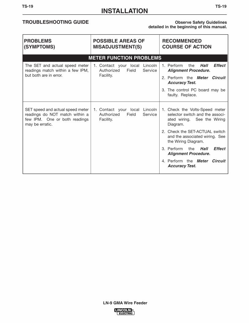
METER FUNCTION PROBLEMS
The arc is unstable or oscillating. 1. Check the welding cables forloose or faulty connections.
2. Make sure the electrode andgas (if used) are correct for theprocess being used.
3. Put the Lincoln power source inthe “Machine Control” mode.Jumper the “BYPASS” pins onthe LN-9 GMA voltage PCboard. Adjust the weld voltagefrom the power source for theprocess being used. If theproblem is NOT resolved, thepower source may be faulty.
1. The LN-9 GMA voltage PCboard may be faulty. Replace.
CAUTIONIf for any reason you do not understand the test procedures or are unable to perform the test/repairs safely, con-tact the Lincoln Electric Service Department for electrical troubleshooting assistance before you proceed. Call1-888-935-3877.
INSTALLATIONTS-19 TS-19
LN-9 GMA Wire Feeder
TROUBLESHOOTING GUIDE Observe Safety Guidelinesdetailed in the beginning of this manual.
PROBLEMS(SYMPTOMS)
POSSIBLE AREAS OFMISADJUSTMENT(S)
RECOMMENDEDCOURSE OF ACTION
The SET and actual speed meterreadings match within a few IPM,but both are in error.
1. Contact your local LincolnAuthorized Field ServiceFacility.
1. Perform the Hall EffectAlignment Procedure.
2. Perform the Meter CircuitAccuracy Test.
3. The control PC board may befaulty. Replace.
SET speed and actual speed meterreadings do NOT match within afew IPM. One or both readingsmay be erratic.
1. Contact your local LincolnAuthorized Field ServiceFacility.
1. Check the Volts-Speed meterselector switch and the associ-ated wiring. See the WiringDiagram.
2. Check the SET-ACTUAL switchand the associated wiring. Seethe Wiring Diagram.
3. Perform the Hall EffectAlignment Procedure.
4. Perform the Meter CircuitAccuracy Test.
METER FUNCTION PROBLEMS

TROUBLESHOOTINGTS-20 TS-20
LN-9 GMA Wire Feeder
TROUBLESHOOTING GUIDE Observe Safety Guidelinesdetailed in the beginning of this manual.
PROBLEMS(SYMPTOMS)
POSSIBLE AREAS OFMISADJUSTMENT(S)
RECOMMENDEDCOURSE OF ACTION
METER FUNCTION PROBLEMS
SET volts and actual volts readingsmatch within a few tenths of a voltwhile welding. However, bothreadings are inaccurate.
1. Put the Lincoln power source inthe "Machine Control" mode.Check to see if the powersource can be set for the arcvoltage required for the process.If not, the power source may befaulty.
2. The control cable may be faulty.Check or replace.
1. Check the voltage sensingleads for continuity (zero ohms).Lead #21 should have continu-ity to the work piece, and #67should have continuity to thebrass conductor block. See theWiring Diagram.
2. Perform the Meter CircuitAccuracy Test.
3. The voltage PC board may befaulty. Replace.
CAUTIONIf for any reason you do not understand the test procedures or are unable to perform the test/repairs safely, con-tact the Lincoln Electric Service Department for electrical troubleshooting assistance before you proceed. Call1-888-935-3877.
The actual volts reading does NOTmatch the SET volts reading withina few tenths of a volt while weld-ing. One reading may be erratic.The LN-9 GMA does NOT shut off.
NOTE: The Pulse Power Filter kitmay slow down the shutdown fea-ture.
1. Make sure the shutdown"BYPASS" pins are NOTjumpered together on the LN-9GMA voltage PC board.
2. Check the voltage sensingleads for continuity (zero ohms).Lead #21 should have continu-ity to the work piece, and #67should have continuity to thebrass conductor block. See theWiring Diagram.
3. Put the Lincoln power source inthe "Machine Control" mode.Check to see if the power sup-ply can be set for the arc volt-age required for the process. Ifnot, the power supply may befaulty.
1. If the actual reading is the prob-lem, check the actual voltsswitch and associated leads.
2. If the SET reading is the prob-lem, check the set volts switchand the associated leads.
3. Check the Volts-Speed selectorswitch and associated leads.
4. The voltage PC board may befaulty. Replace.

TROUBLESHOOTINGTS-21 TS-21
LN-9 GMA Wire Feeder
TROUBLESHOOTING GUIDE Observe Safety Guidelinesdetailed in the beginning of this manual.
PROBLEMS(SYMPTOMS)
POSSIBLE AREAS OFMISADJUSTMENT(S)
RECOMMENDEDCOURSE OF ACTION
STARTING PROBLEMS
The output voltage is too low tostart the weld.
1. Check the welding cables forloose or faulty connections.
2. Put the Lincoln power source inthe "Machine Control" mode.Jumper the "BYPASS" pins onthe LN-9 GMA voltage PCboard. Adjust the weld voltagefrom the power source for theprocess being used. If the cor-rect voltage cannot be set, thepower source may be faulty.
3. Check for correct control cableconnections to the power sup-ply.
4. The control cable may be faulty.Check or replace.
1. Check the voltage controlpotentiometer (R3) and theassociated leads. See theWiring Diagram.
2. The voltage PC board may befaulty. Replace.
CAUTIONIf for any reason you do not understand the test procedures or are unable to perform the test/repairs safely, con-tact the Lincoln Electric Service Department for electrical troubleshooting assistance before you proceed. Call1-888-935-3877.

TROUBLESHOOTINGTS-22 TS-22
LN-9 GMA Wire Feeder
TROUBLESHOOTING GUIDE Observe Safety Guidelinesdetailed in the beginning of this manual.
PROBLEMS(SYMPTOMS)
POSSIBLE AREAS OFMISADJUSTMENT(S)
RECOMMENDEDCOURSE OF ACTION
STARTING PROBLEMS
Voltage seems to be too high orthe arc flares at the start of weld.Welding is good.
1. Adjust the "start" trimmer on thevoltage PC board. It should beonly slightly higher than the weldvoltage. See Starting Charac-teristics in the Operation sec-tion of this manual.
2. Put the Lincoln power source inthe "Machine Control" mode.Jumper the "BYPASS" pins onthe LN-9 GMA voltage PCboard. Adjust the weld voltagefrom the power source for theprocess being used. If the cor-rect voltage cannot be set, thepower source may be faulty.
3. Check for correct control cableconnections to the power sup-ply.
1. The LN-9 GMA voltage PCboard may be faulty. Replace.
CAUTIONIf for any reason you do not understand the test procedures or are unable to perform the test/repairs safely, con-tact the Lincoln Electric Service Department for electrical troubleshooting assistance before you proceed. Call1-888-935-3877.

TROUBLESHOOTINGTS-23 TS-23
LN-9 GMA Wire Feeder
TROUBLESHOOTING GUIDE Observe Safety Guidelinesdetailed in the beginning of this manual.
PROBLEMS(SYMPTOMS)
POSSIBLE AREAS OFMISADJUSTMENT(S)
RECOMMENDEDCOURSE OF ACTION
STARTING PROBLEMS
The arc voltage appears to rise tooslowly or stubs or blasts at thestart of a weld. Once started thewelding is good.
NOTE: Pulse Power 500 operationwith a filter kit may exhibit thesesymptoms.
1. Adjust the "start" trimmer onthe voltage PC board. It shouldbe slightly higher than the weldvoltage. See Starting Charac-teristics in the Operation sec-tion of this manual.
3. Put the Lincoln power source inthe "Machine Control" mode.Jumper the "BYPASS" pins onthe LN-9 GMA voltage PCboard. Adjust the weld voltagefrom the power source for theprocess being used. If the cor-rect voltage cannot be set, thepower source may be faulty.
4. Check for correct control cableconnections to the power sup-ply.
1. The voltage PC board may befaulty. Replace.
CAUTIONIf for any reason you do not understand the test procedures or are unable to perform the test/repairs safely, con-tact the Lincoln Electric Service Department for electrical troubleshooting assistance before you proceed. Call1-888-935-3877.

TROUBLESHOOTINGTS-24 TS-24
LN-9 GMA Wire Feeder
T1 TRANSFORMER TEST
WARNING
Service and repair should be performed by only Lincoln Electric factory trained person-nel. Unauthorized repairs performed on this equipment may result in danger to the tech-nician or machine operator and will invalidate your factory warranty. For your safety andto avoid electrical shock, please observe all safety notes and precautions detailedthroughout this manual.
If for any reason you do not understand the test procedures or are unable to perform thetest/repairs safely, contact the Lincoln Electric Service Department for electrical trou-bleshooting assistance before you proceed. Call 1-888-935-3877.
DESCRIPTION
This test will aid the technician in determining if the T1 transformer is functioning.
MATERIALS NEEDED
115VAC power supplyPhillips head screwdriverVolt/ohmmeter (multimeter)
This procedure takes approximately 20 minutes to perform.

TROUBLESHOOTINGTS-25 TS-25
LN-9 GMA Wire Feeder
T1 TRANSFORMER TEST (continued)
TEST PROCEDURE
1. Remove input power to the LN-9 GMA wirefeeder.
2. Using the phillips head screwdriver, removethe screws holding the left side coverassembly.
3. Disconnect lead #532 from the power PCboard terminal. See Figure F.1.
Electric Shock can kill.
• With power applied,there are high voltagesinside the wire feeder.Do not reach into thewire feeder or touch anyinternal part of the wirefeeder while power isapplied.
4. Apply power (115VAC) to the T1 transformerprimary leads #31 and #532. See Figure F.1and the Wiring Diagram.
5. Using the volt-ohmmeter, check for 28VACat secondary leads #526 and #527. SeeFigure F.1. Place the meter probes wherethe leads attach to the power PC board ter-minals.
WARNING
FIGURE F.1 – LEAD #532 AT POWER PC BOARD
115 VAC
T1TRANSFORMER
LEAD 526
LEAD 532
LEAD 31
LEAD 527

TROUBLESHOOTINGTS-26 TS-26
LN-9 GMA Wire Feeder
6. Using the volt/ohmmeter, check for 10VACat secondary leads #601 and #602.Typically, these leads are yellow. Place theprobes at the lead splices. See Figure F.2.
7. With 115VAC applied to the primary leads#532 and #31, if either or both of the sec-ondary voltages are missing or low the T1transformer may be faulty. Replace thetransformer.
8. After the test is completed, disconnect the115VAC from the T1 transformer primaryleads. Reconnect lead #532 to the powerPC board terminal. Close the left side coverassembly and re-assemble the screws.
T1 TRANSFORMER TEST (continued)
FIGURE F.2 – SECONDARY LEADS #601 AND #602 AT LEAD SPLICES
LEAD 601LEAD 602

TROUBLESHOOTINGTS-27 TS-27
LN-9 GMA Wire Feeder
WARNING
T2 TRANSFORMER TEST
Service and repair should be performed by only Lincoln Electric factory trained personnel.Unauthorized repairs performed on this equipment may result in danger to the technician ormachine operator and will invalidate your factory warranty. For your safety and to avoid elec-trical shock, please observe all safety notes and precautions detailed throughout this manu-al.
If for any reason you do not understand the test procedures or are unable to perform thetest/repairs safely, contact the Lincoln Electric Service Department for electrical trou-bleshooting assistance before you proceed. Call 1-888-935-3877.
DESCRIPTION
This test will aid the technician in determining if the T2 transformer is functioning.
MATERIALS NEEDED
115VAC power supplyPhillips head screwdriverVolt/ohmmeter (multimeter)
This procedure takes approximately 20 minutes to perform.

TROUBLESHOOTINGTS-28 TS-28
LN-9 GMA Wire Feeder
T2 TRANSFORMER TEST (continued)
FIGURE F.3 – “PROTECTION CIRCUIT TROUBLESHOOTING” NAMEPLATE
PROTECTION CIRCUITTROUBLESHOOTING NAMEPLATE
TEST PROCEDURE
1. Remove input power to the LN-9 GMA wirefeeder.
2. Using the phillips head screwdriver, removethe screws holding the left side coverassembly.
3. Lift the right side cover assembly.
4. Using the phillips head screwdriver, removethe two screws from the Protection CircuitTroubleshooting nameplate. Remove thenameplate as far as the lead length willallow. See Figure F.3.

TROUBLESHOOTINGTS-29 TS-29
LN-9 GMA Wire Feeder
T2 TRANSFORMER TEST (continued)
4. Locate the T2 transformer primary lead#32A connected to the 5 amp circuit break-er. Remove lead #32A from the circuitbreaker. See Figure F.4 and the WiringDiagram.
5. Lift the left side cover assembly.
6. Locate T2 transformer primary lead #531connected to the R1 2-ohm resistor. Seethe Wiring Diagram. See Figure F.4.
FIGURE F.4 – T2 PRIMARY LEADS #32A AT 5 AMP CIRCUIT BREAKER AND #531 AT R1 RESISTOR
LEAD 32A
LEAD 531
R1 RESISTOR
CIRCUITBREAKER

TROUBLESHOOTINGTS-30 TS-30
LN-9 GMA Wire Feeder
T2 TRANSFORMER TEST (continued)
Electric Shock can kill.
• With power applied,there are high voltagesinside the wire feeder.Do not reach into thewire feeder or touch anyinternal part of the wirefeeder while power isapplied.
7. Insulate the T2 transformer primary leads#531 and #32A and apply 115 VAC power.See the Wiring Diagram and Figure F.4.
8. Using the volt/ohmmeter, check forapproximately 24VAC at the T2 trans-former secondary leads #621 and #620.Place the probes where the leads connecton the trigger PC board. See Figure F.5.
9. With 115VAC applied to the primary leads#531 and #32A, if the secondary voltageis missing or low the T2 transformer maybe faulty. Replace the T2 transformer.
10. After the test is completed, disconnect the115VAC from the T2 transformer primaryleads #531 and #32A. Reconnect lead #32to the circuit breaker. Re-attach theProtection Circuit Troubleshooting name-plate. Close the right and left side coverassemblies and replace all previouslyremoved screws.
FIGURE F.5 – T2 SECONDARY LEADS #621 AND #620 ON TRIGGER PC BOARD
LEAD621
TRIGGERPC BOARD
LEAD620
WARNING

TROUBLESHOOTINGTS-31 TS-31
LN-9 GMA Wire Feeder
WARNING
WIRE DRIVE MOTOR TEST
Service and repair should be performed by only Lincoln Electric factory trained personnel.Unauthorized repairs performed on this equipment may result in danger to the technician ormachine operator and will invalidate your factory warranty. For your safety and to avoid elec-trical shock, please observe all safety notes and precautions detailed throughout this man -ual.
If for any reason you do not understand the test procedures or are unable to perform thetest/repairs safely, contact the Lincoln Electric Service Department for electrical trou-bleshooting assistance before you proceed. Call 1-888-935-3877.
DESCRIPTION
This test will help determine if the drive motor is functioning properly.
MATERIALS NEEDED
Phillips head screwdriverAnalog volt/ohmmeter (multimeter)
This procedure takes approximately 12 minutes to perform.

TROUBLESHOOTINGTS-32 TS-32
LN-9 GMA Wire Feeder
WIRE DRIVE MOTOR TEST (continued)
FIGURE F.6 – LEAD #539 AND #541 AT POWER PC BOARD TERMINAL STRIP
LEAD 539
LEAD 541
TEST PROCEDURE
1. Remove input power to the LN-9 GMA wirefeeder.
2. Remove any electrode wire or disengagethe drive rolls.
3. Using the phillips head screwdriver, removethe screws from the left side cover assem-bly.
4. Lift the left side cover assembly.
5. Locate leads #539 and #541 at the powerPC board terminal strip. See Figure F.6.

ELECTRIC SHOCK can kill.
• With power applied,there are high voltagesinside the wire feeder.Do not reach into thewire feeder or touch anyinternal part of the wirefeeder while power isapplied.
6. Apply 115 VAC power.
7. With the gun trigger activated or the gunterminals jumpered together (see the WiringDiagram), check the motor armature volts atleads #541(+) and #539(-). Normal is 5 to95VDC depending on the wire feed speedsetting. As the armature voltage isincreased the wire feed speed shouldincrease.
8. If the above voltages are present and themotor does not operate, the motor, motorbrushes or gear box may be faulty.
If the armature voltage is missing or not cor-rect, the power board or 1CR relay may befaulty.
If the motor is running at high speed and thearmature voltage is high and uncontrollable,proceed with the Hall Effect Module Test.
TROUBLESHOOTINGTS-33 TS-33
LN-9 GMA Wire Feeder
WIRE DRIVE MOTOR TEST (continued)
WARNING

HALL EFFECT MODULE TEST AND ALIGNMENT
Service and repair should be performed by only Lincoln Electric factory trained personnel.Unauthorized repairs performed on this equipment may result in danger to the technician ormachine operator and will invalidate your factory warranty. For your safety and to avoid elec-trical shock, please observe all safety notes and precautions detailed throughout this man -ual.
If for any reason you do not understand the test procedures or are unable to perform thetest/repairs safely, contact the Lincoln Electric Service Department for electrical trou-bleshooting assistance before you proceed. Call 1-888-935-3877.
DESCRIPTION
This test will help determine if the Hall Effect Module is correctly aligned and functioningproperly.
MATERIALS NEEDED
9/16” WrenchAnalog volt/ohmmeter (multimeter)Phillips head screwdriver
TROUBLESHOOTINGTS-34 TS-34
LN-9 GMA Wire Feeder
WARNING
The Hall Effect Module Test takes approximately10 minutes to perform.
The Hall Effect Alignment Procedure takes approximately10 minutes to perform.

TROUBLESHOOTINGTS-35 TS-35
LN-9 GMA Wire Feeder
HALL EFFECT MODULE FEEDBACK TEST PROCEDURE
1. Remove the input power to the LN-9 GMAwire feeder.
2. Remove any electrode wire or disengagethe drive rolls.
3. Using the phillips head screwdriver, removethe screws from the left side cover assembly.
4. Lift the left side cover.
5. Locate the hall effect leads #510, #525 and#555 on the control PC board. See FigureF.7.
HALL EFFECT MODULE TEST AND ALIGNMENT (continued)
FIGURE F.7 – LEADS #525, #510, #555 ON CONTROL PC BOARD
LEAD525
LEAD510
LEAD555

ELECTRIC SHOCK can kill.
• With power applied,there are high voltagesinside the wire feeder.Do not reach into thewire feeder or touch anyinternal part of the wirefeeder while power isapplied.
6. Apply input power to the LN-9 GMA andtest for 15VDC at leads #525(+) to #510(-).This is the supply voltage from the controlPC board to the hall effect module. If thecorrect voltage is present, proceed to thenext step. If the voltage is missing, checkthe wiring and perform the General PowerSupply Test.
7. With the gun trigger activated or the gunterminals jumpered together (see the WiringDiagram), check leads #555(+) to #510(-) forthe presence of between 4.5 - 10.5VDC.(The motor must be running.) This is thefeedback voltage from the hall effect mod-ule to the control PC board. This voltage isdependent upon motor speed. If the feed-back voltage is missing or does not varywith motor speed, the hall effect modulemay be faulty.
TROUBLESHOOTINGTS-36 TS-36
LN-9 GMA Wire Feeder
WARNING
HALL EFFECT MODULE TEST AND ALIGNMENT (continued)

HALL EFFECT MODULE ALIGNMENT TEST PROCEDURE
The LN-9 GMA wire speed sensor is a threelead hall-effect device encased in an externallythreaded housing. It is screwed into a mount-ing plate on the motor side of the wire drivegearbox. See Figure F.8.
1. Remove the input power to the LN-9 GMA.
2. Check that the module mounting plate isscrewed securely to the side of the gearboxand seated flush against the top surface.
3. Gently screw the hall effect module into themounting plate until it just touches andstops against the rotating part inside thegearbox.
4. Back the module out 1/2 turn. Then, usingthe 9/16” wrench, carefully snug the modulelocknut without rotating the module posi-tion.
5. After the hall effect module tests are com-pleted, remove the jumper from the gun ter-minals (if used). Close the left side casecover assembly and reattach the screws.
INSTALLATIONTS-37 TS-37
LN-9 GMA Wire Feeder
HALL EFFECT MODULE TEST AND ALIGNMENT (continued)
FIGURE F.8 – HALL EFFECT MODULE LOCATION
HALL-EFFECTMODULE

TROUBLESHOOTINGTS-38 TS-38
LN-9 GMA Wire Feeder
WARNING
VOLTMETER ACCURACY TEST
Service and repair should be performed by only Lincoln Electric factory trained personnel.Unauthorized repairs performed on this equipment may result in danger to the technician ormachine operator and will invalidate your factory warranty. For your safety and to avoid elec-trical shock, please observe all safety notes and precautions detailed throughout this manual.
If for any reason you do not understand the test procedures or are unable to perform thetest/repairs safely, contact the Lincoln Electric Service Department for electrical trou-bleshooting assistance before you proceed. Call 1-888-935-3877.
DESCRIPTION
This test will help determine if the LN-9 GMA voltmeter is providing accurate readings.
MATERIALS NEEDED
Phillips head screwdriverDigital volt/ohmmeter (multimeter) with at least 3-1/2 digits and ± 0.5% accuracy
This procedure takes approximately 8 minutes to perform.

TROUBLESHOOTINGTS-39 TS-39
LN-9 GMA Wire Feeder
VOLTMETER ACCURACY TEST (continued)
FIGURE F.9 – VOLTMETER CONNECTION POINT
TEST PROCEDURE
Perform the following checks with the LN-9GMA wire feeder connected to a Lincoln CVwelding power source according to the properconnection diagram. (See the Installation sec-tion of this manual.)
See Figure F.9 for this test.
1. Lift the right side cover assembly.
2. Connect the test meter (see MaterialsNeeded) between the brass conductor blockon the wire feeder and the work piece.
BRASSCONDUCTOR
BLOCK

ELECTRIC SHOCK can kill.
• With power applied,there are high voltagesinside the wire feeder. Donot reach into the wirefeeder or touch any inter-nal part of the wire feederwhile power is applied.
3. With the LN-9 GMA gun trigger closed or thegun terminals jumpered together (see theWiring Diagram), the test meter readingshould match the LN-9 GMA ACTUAL voltsreading within ± 0.5 volts. If it does not,check the integrity and placement of the volt-age sensing leads #21 and #67. Perform theMeter Circuit Accuracy Test.
4. Remove the test voltmeter and, while weld-ing, compare the SET volts and ACTUALvolts meter readings. Depending upon thearc voltage characteristics of the weldingprocess being used, the ACTUAL readingmay vary somewhat around an averagevalue. The average ACTUAL reading shouldmatch the SET reading within ± 0.5 volts. Ifnot, refer to the Meter Circuit AccuracyTest.
5. If no further tests are required, remove thejumper from the gun terminals (if used) andclose the left case side cover assembly.
TROUBLESHOOTINGTS-40 TS-40
LN-9 GMA Wire Feeder
WARNING
VOLTMETER ACCURACY TEST (continued)

TROUBLESHOOTINGTS-41 TS-41
LN-9 GMA Wire Feeder
WARNING
METER CIRCUIT ACCURACY TEST
Service and repair should be performed by only Lincoln Electric factory trained personnel.Unauthorized repairs performed on this equipment may result in danger to the technician ormachine operator and will invalidate your factory warranty. For your safety and to avoid elec-trical shock, please observe all safety notes and precautions detailed throughout this manual.
If for any reason you do not understand the test procedures or are unable to perform thetest/repairs safely, contact the Lincoln Electric Service Department for electrical trou-bleshooting assistance before you proceed. Call 1-888-935-3877.
DESCRIPTION
This test will help determine if the LN-9 GMA meter circuit is functioning properly.
MATERIALS NEEDED
Phillips head screwdriverDigital volt/ohmmeter (multimeter) with at least 3-1/2 digits and ± 0.5% accuracySlot head screwdriver3/8" Nut driver
This procedure takes approximately 17 minutes to perform.

TROUBLESHOOTINGTS-42 TS-42
LN-9 GMA Wire Feeder
METER CIRCUIT ACCURACY TEST (continued)
FIGURE F.10 – METER PC BOARD LOCATIONS AND COVER
MOUNTING SCREWS
TEST PROCEDURE
1. Remove input power to the LN-9 GMA wirefeeder.
2. Lift the right side cover assembly and removethe two screws holding the meter cover tothe right side assembly. Carefully remove themeter cover. See Figure F.10.
3. Locate and gain access to the meter PCboard. See Figure F.10.
4. Apply input power to the wire feeder.
ELECTRIC SHOCK can kill.
• With power applied, thereare high voltages insidethe wire feeder. Do notreach into the wire feederor touch any internal partof the wire feeder whilepower is applied.
WARNING

TROUBLESHOOTINGTS-43 TS-43
LN-9 GMA Wire Feeder
METER CIRCUIT ACCURACY TEST (continued)
5. Test for AC supply to the meter PC board.
Check for 8 to 11 VAC from lead #601 to#602. See Figure F.11.
NOTE: The coating will have to be removedfrom the test points.
6. Test for DC volts on the meter PC board.
Check for 4.75 to 5.25 VDC from TP5 to lead#510C. See Figure F.11.
NOTE: The coating will have to be removedfrom the test points.
If the display is NOT lit and the correct DC volt-age is present at TP5 to lead #510C, the digitalmeter may be faulty. Replace the digital meter.
If AC voltage IS present at leads #601 to #602and the DC voltage is missing, the meter PCboard may be faulty.
FIGURE F.11 – METER PC BOARD TEST POINTS
561
601
602
510C
517
560
TP5
TP4
519
TROUBLESHOOTINGTS-44 TS-44
LN-9 GMA Wire Feeder
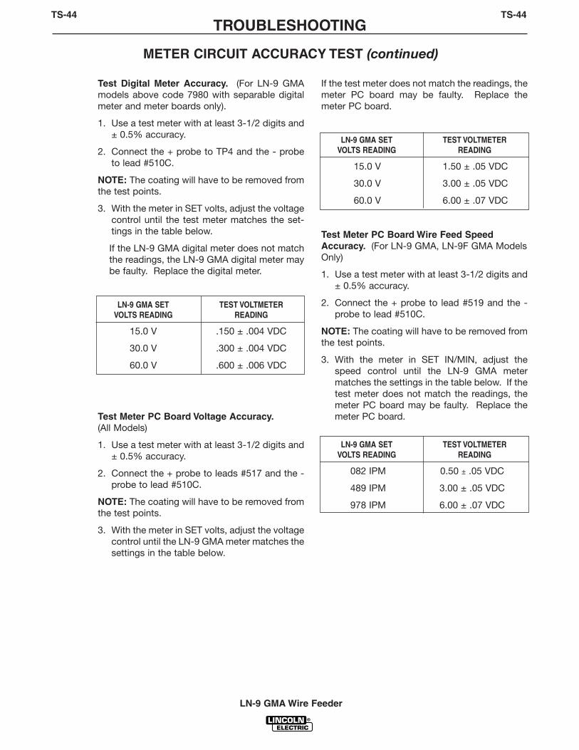
METER CIRCUIT ACCURACY TEST (continued)
Test Digital Meter Accuracy. (For LN-9 GMAmodels above code 7980 with separable digitalmeter and meter boards only).
1. Use a test meter with at least 3-1/2 digits and± 0.5% accuracy.
2. Connect the + probe to TP4 and the - probeto lead #510C.
NOTE: The coating will have to be removed fromthe test points.
3. With the meter in SET volts, adjust the voltagecontrol until the test meter matches the set-tings in the table below.
If the LN-9 GMA digital meter does not matchthe readings, the LN-9 GMA digital meter maybe faulty. Replace the digital meter.
LN-9 GMA SET TEST VOLTMETERVOLTS READING READING
15.0 V .150 ± .004 VDC
30.0 V .300 ± .004 VDC
60.0 V .600 ± .006 VDC
Test Meter PC Board Voltage Accuracy. (All Models)
1. Use a test meter with at least 3-1/2 digits and± 0.5% accuracy.
2. Connect the + probe to leads #517 and the -probe to lead #510C.
NOTE: The coating will have to be removed fromthe test points.
3. With the meter in SET volts, adjust the voltagecontrol until the LN-9 GMA meter matches thesettings in the table below.
If the test meter does not match the readings, themeter PC board may be faulty. Replace themeter PC board.
LN-9 GMA SET TEST VOLTMETERVOLTS READING READING
15.0 V 1.50 ± .05 VDC
30.0 V 3.00 ± .05 VDC
60.0 V 6.00 ± .07 VDC
Test Meter PC Board Wire Feed SpeedAccuracy. (For LN-9 GMA, LN-9F GMA ModelsOnly)
1. Use a test meter with at least 3-1/2 digits and± 0.5% accuracy.
2. Connect the + probe to lead #519 and the -probe to lead #510C.
NOTE: The coating will have to be removed fromthe test points.
3. With the meter in SET IN/MIN, adjust thespeed control until the LN-9 GMA metermatches the settings in the table below. If thetest meter does not match the readings, themeter PC board may be faulty. Replace themeter PC board.
LN-9 GMA SET TEST VOLTMETERVOLTS READING READING
082 IPM 0.50 ± .05 VDC
489 IPM 3.00 ± .05 VDC
978 IPM 6.00 ± .07 VDC

Test Meter PC Board Wire Feed Speed Accuracy.(Metric Models Only)
1. Use a test meter with at least 3-1/2 digits and ± 0.5% accuracy.
2. Connect the + probe to lead called for in the tablebelow and the - probe to lead #510C.
NOTE: The coating will have to be removed from thetest points.
3. With the meter in SET M/MIN, adjust the speedcontrol until the LN-9 GMA meter matches the set-tings in the table below. If the test meter does notmatch the readings, the meter PC board may befaulty. Replace the meter PC board.
TROUBLESHOOTINGTS-45 TS-45
LN-9 GMA Wire Feeder
METER CIRCUIT ACCURACY TEST (continued)
METRIC MODEL METRIC RANGE SET M/MIN READING TEST VOLTMETER READING
LN-9 GMA or LN-9F GMA LO 8.28 LEAD #5602.00 ± .05VDC
HI 24.8 LEAD #5616.00 ± .07VDC

TROUBLESHOOTINGTS-46 TS-46
LN-9 GMA Wire Feeder
WARNING
WIRE SPEED ACCURACY TEST
Service and repair should be performed by only Lincoln Electric factory trained personnel.Unauthorized repairs performed on this equipment may result in danger to the technician ormachine operator and will invalidate your factory warranty. For your safety and to avoid elec-trical shock, please observe all safety notes and precautions detailed throughout this manual.
If for any reason you do not understand the test procedures or are unable to perform thetest/repairs safely, contact the Lincoln Electric Service Department for electrical trou-bleshooting assistance before you proceed. Call 1-888-935-3877.
DESCRIPTION
This test will help determine if the LN-9 GMA is providing the proper wire feed inches per rev-olution of the drive roll.
MATERIALS NEEDED
Phillips head screwdriverRuler or other linear measuring device
This procedure takes approximately 12 minutes to perform.

TROUBLESHOOTINGTS-47 TS-47
LN-9 GMA Wire Feeder
WIRE SPEED ACCURACY TEST (continued)
TEST PROCEDURE
Perform the following checks with the LN-9 GMAwire feeder connected to a Lincoln CV weldingpower source according to the proper connec-tion diagram. (See the Installation section ofthis manual.)
A. Check for the proper wire feed inches perrevolution of the drive roll.
1. Set the LN-9 GMA wire speed control forbetween 50 and 120 IPM (1.27 to 3.17M/MIN).
2. Measure the precise length of wire fed byexactly 10 revolutions of the drive rolls.This measured length should be 53.0 ± .8inches (1.35 ± .02 meters). If not, theremay be a problem with the wire or thewire feed path. See the Trouble shootingGuide (Feeding Problems) in this sec-tion of the manual. Also check for correctdrive roll tension adjustment.
B. Check for the proper drive roll revolutionsper minute.
1. Adjust the LN-9 GMA wire speed controlfor the LN-9 GMA ACTUAL speed meterreadings given in the table below.
2. Compare the corresponding LN-9 GMAdrive roll RPM (counted revolutions in 60seconds) and LN-9 GMA SET speedmeter readings with the table below. Thenumbers should match. If not, performthe Meter Circuit Accuracy Test.
MODEL ACTUAL SPEED METER MEASURED SET SPEED METERREADING DRIVE ROLL READING
SPEED
MODEL IN/MIN M/MIN RPM IN/MIN M/MIN
LN-9 GMA 161 4.1 30 ± 1/2 161 ± 3 04.1 ± .1or 322 8.2 60 ± 1 322 ± 3 08.2 ± .1
LN-9F GMA

TROUBLESHOOTINGTS-48 TS-48
LN-9 GMA Wire Feeder
WARNING
OUT OF VOLTAGE RANGE SHUT DOWN TEST
Service and repair should be performed by only Lincoln Electric factory trained personnel.Unauthorized repairs performed on this equipment may result in danger to the technician ormachine operator and will invalidate your factory warranty. For your safety and to avoid elec-trical shock, please observe all safety notes and precautions detailed throughout this manual.
If for any reason you do not understand the test procedures or are unable to perform thetest/repairs safely, contact the Lincoln Electric Service Department for electrical trou-bleshooting assistance before you proceed. Call 1-888-935-3877.
DESCRIPTION
This test will help determine if the out-of-voltage range shut down circuitry is functioningproperly.
MATERIALS NEEDED
Phillips head screwdriverVolt/ohmmeter (multimeter)Jumper wire
This procedure takes approximately 18 minutes to perform.

TROUBLESHOOTINGTS-49 TS-49
LN-9 GMA Wire Feeder
OUT OF VOLTAGE RANGE SHUT DOWN TEST (continued)
FIGURE F.12 – VOLTAGE PC BOARD WITH JUMPERS
BYPASSPINS
1/8 AMPFUSE
TEST PROCEDURE
1. Remove input power to the LN-9 GMA wirefeeder.
2. Using the phillips head screwdriver, removethe screws from the left side cover assembly.
3. Lift the left side cover assembly.
4. Locate the voltage PC board. Jumper togeth-er the "BYPASS" pins on the LN-9 GMA volt-age PC board. See Figure F.12. (On older volt-age boards these pins may be labeled "B".)This should disable the shut down circuit.
ELECTRIC SHOCK can kill.
• With power applied,there are high voltagesinside the wire feeder.Do not reach into thewire feeder or touch anyinternal part of the wirefeeder while power is
applied.
5. Connect to a Lincoln Electric CV powersource per connection diagram. See theInstallation section of this manual.
6. Start welding and observe the ACTUAL volt-age reading on the LN-9 GMA digital meter.The actual voltage must match the SET volt-age within ± 0.5V. If it does NOT, the LN-9GMA is designed to shut down.
7. If the LN-9 GMA continues to shut down withthe "BYPASS" pins jumpered together, thevoltage PC board may be faulty.
WARNING

TROUBLESHOOTINGTS-50 TS-50
LN-9 GMA Wire Feeder
OUT OF VOLTAGE RANGE SHUT DOWN TEST (continued)
8. If the ACTUAL voltage reading is zero, thesensing leads may be faulty. Check thecontinuity (zero ohms) of leads #21 and #67.Lead #21 must have continuity to the work-piece, and #67 must have continuity to theelectrode. Also check the 1/8 amp fuse onthe voltage PC board.
9. Check the polarity switches in the LN-9GMA and the Lincoln power source andtheir associated leads. Set the switches tothe same polarity as the electrode. See theWiring Diagram.
10. If the ACTUAL voltage reading is differentfrom the SET voltage reading, the powersource may not be capable of producing therequired arc voltage, the control cable maybe faulty or misconnected, or the LN-9 GMAvoltage PC board may be faulty.
11. After all tests are complete, remove inputpower to the wire feeder and remove thejumper you placed on the "BYPASS" pins onthe voltage PC board. Reattach the left caseside cover assembly.

TROUBLESHOOTINGTS-51 TS-51
LN-9 GMA Wire Feeder
WARNING
GENERAL POWER SUPPLY TESTS
Service and repair should be performed by only Lincoln Electric factory trained personnel.Unauthorized repairs performed on this equipment may result in danger to the technician ormachine operator and will invalidate your factory warranty. For your safety and to avoid elec-trical shock, please observe all safety notes and precautions detailed throughout this manual.
If for any reason you do not understand the test procedures or are unable to perform thetest/repairs safely, contact the Lincoln Electric Service Department for electrical trou-bleshooting assistance before you proceed. Call 1-888-935-3877.
DESCRIPTION
These tests will help determine if the power PC board is supplying the correct voltage to thecontrol PC board and the voltage PC board.
MATERIALS NEEDED
Phillips head screwdriverVolt/ohmmeter (multimeter)
This procedure takes approximately 18 minutes to perform.

TROUBLESHOOTINGTS-52 TS-52
LN-9 GMA Wire Feeder
GENERAL POWER SUPPLY TESTS (continued)
TEST PROCEDURE1. Remove input power to the LN-9 GMA wire
feeder.
2. Using the phillips head screwdriver, removethe screws from the left side cover assembly.
3. Lift the left side cover assembly.
4. Locate the power PC board and the controlPC board in the wire feeder main assembly;locate the voltage PC board in the left sidecover.
ELECTRIC SHOCK can kill.
• With power applied, thereare high voltages insidethe wire feeder. Do notreach into the wire feederor touch any internal partof the wire feeder whilepower is applied.
5. Apply power (115VAC) to the wire feeder atthe correct pins. See the Wiring Diagram.
6. Perform the power supply checks asdescribed in the table below. If any of thereadings are incorrect (out of range) or miss-ing, the power PC board may be faulty.
NOTE: Do NOT unplug the Molex connector.
7. Also perform the T1 Transformer Test.
WARNING

TROUBLESHOOTINGTS-53 TS-53
LN-9 GMA Wire Feeder
GENERAL POWER SUPPLY CHECKS
CHECKPOINT TEST CONNECTOR LEAD NO. NORMALLOCATION DESCRIPTION PLUG PIN NO. ACCEPTABLE
VOLTAGEREADING
CONTROL P.C. CHECKBOARD +15VDC
CONNECTOR SUPPLY FROMPLUG POWER 525(+) 13.5 - 15.5 VDC
BOARD TO 510(-)CONTROL 10(+)
BOARD 9(-)
CONTROL P.C. CHECK - 10 VDCBOARD SUPPLY FROM
CONNECTOR POWER 500(-) 9.2 - 10.8 VDCPLUG BOARD TO 510(+)
CONTROL 14(-)BOARD 9(+)
VOLTAGE P.C. CHECKBOARD UPPER + 15 VDCCONNECTOR SUPPLY FROM
PLUG NEXT TO POWER 525(+) 13.5 - 15.5 VDC"F" AND “S” BOARD TO 510(-)
PINS VOLTAGE 4(+)BOARD 6(-)
VOLTAGE P.C.BOARD UPPERCONNECTOR 510(+)
PLUG NEXT TO6(+)"F" AND "S" CHECK - 10 VDC
PINS SUPPLY FROMPOWER 9.2 - 10.8 VDC
BOARD TOVOLTAGE P.C. VOLTAGE
BOARD LOWER BOARDCONNECTOR 500(-)
PLUG NEXT TO 4(-)PLASTIC
COVEREDRELAY
GENERAL POWER SUPPLY TESTS (continued)
525
510
500
510
525
510
510
500


• Sales and Service through Subsidiaries and Distributors Worldwide •
Cleveland, Ohio 44117-1199 U.S.A. TEL: 216.481.8100 FAX: 216.486.1751 WEB SITE: www.lincolnelectric.com
• World's Leader in Welding and Cutting Products •