Embed Size (px)
Citation preview
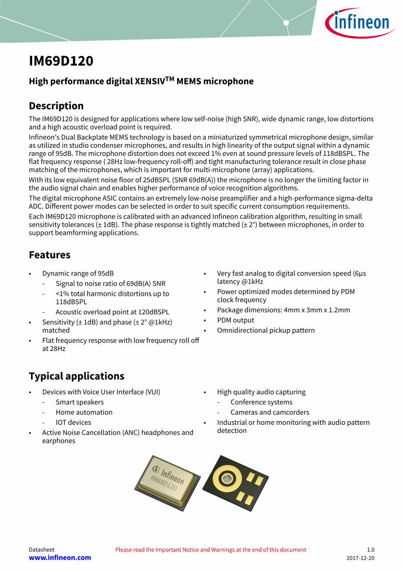
IM69D120High performance digital XENSIVTM MEMS microphone
DescriptionThe IM69D120 is designed for applications where low self-noise (high SNR), wide dynamic range, low distortionsand a high acoustic overload point is required.Infineon's Dual Backplate MEMS technology is based on a miniaturized symmetrical microphone design, similaras utilized in studio condenser microphones, and results in high linearity of the output signal within a dynamicrange of 95dB. The microphone distortion does not exceed 1% even at sound pressure levels of 118dBSPL. Theflat frequency response ( 28Hz low-frequency roll-off) and tight manufacturing tolerance result in close phasematching of the microphones, which is important for multi-microphone (array) applications.With its low equivalent noise floor of 25dBSPL (SNR 69dB(A)) the microphone is no longer the limiting factor inthe audio signal chain and enables higher performance of voice recognition algorithms.The digital microphone ASIC contains an extremely low-noise preamplifier and a high-performance sigma-deltaADC. Different power modes can be selected in order to suit specific current consumption requirements.Each IM69D120 microphone is calibrated with an advanced Infineon calibration algorithm, resulting in smallsensitivity tolerances (± 1dB). The phase response is tightly matched (± 2°) between microphones, in order tosupport beamforming applications.
Features• Dynamic range of 95dB
- Signal to noise ratio of 69dB(A) SNR- <1% total harmonic distortions up to
118dBSPL- Acoustic overload point at 120dBSPL
• Sensitivity (± 1dB) and phase (± 2° @1kHz)matched
• Flat frequency response with low frequency roll offat 28Hz
• Very fast analog to digital conversion speed (6µslatency @1kHz
• Power optimized modes determined by PDMclock frequency
• Package dimensions: 4mm x 3mm x 1.2mm• PDM output• Omnidirectional pickup pattern
Typical applications• Devices with Voice User Interface (VUI)
- Smart speakers- Home automation- IOT devices
• Active Noise Cancellation (ANC) headphones andearphones
• High quality audio capturing- Conference systems- Cameras and camcorders
• Industrial or home monitoring with audio patterndetection
Datasheet Please read the Important Notice and Warnings at the end of this document 1.0www.infineon.com 2017-12-20
Use cases• Below 1% total harmonic distortion
- Voice command during music from the loudspeaker
- Effective active noise cancellation even closeto loud noise source
- Recordings in a discotheque or at a rockconcert
• High Signal to noise ratio- Far field audio signal pick-up- Low volume audio and whispered voice
capturing- Microphone noise is no longer limiting the
audio chain
• Sensitivity and phase matching- Full utilization of voice algorithms capability- Audio beam forming- High and precise attenuation of background
noise• Power optimized modes
- Low current consumption for always onapplications
- Long operating time of battery powereddevices
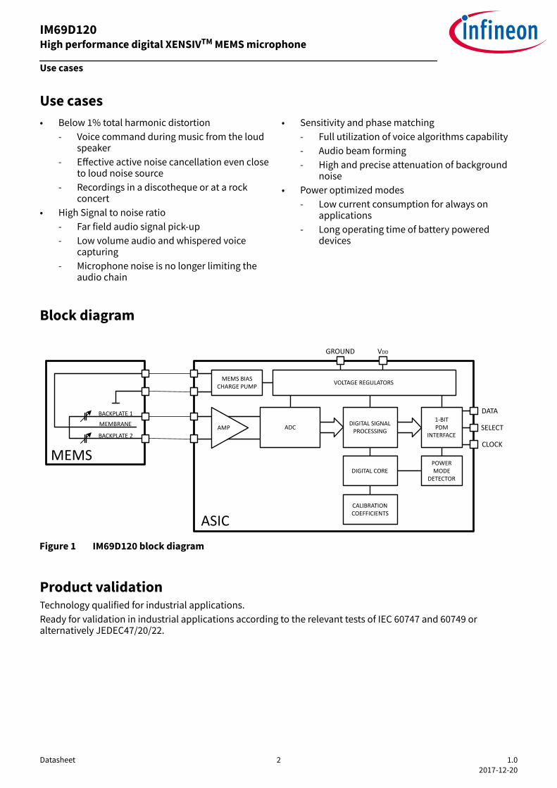
Block diagram
DIGITAL SIGNAL PROCESSING
VOLTAGE REGULATORS
POWER MODE
DETECTOR
1-BITPDM
INTERFACE
CALIBRATION COEFFICIENTS
DIGITAL CORE
VDDGROUND
DATA
SELECT
CLOCK
AMP
MEMS BIAS CHARGE PUMP
ADC
MEMS
BACKPLATE 1
BACKPLATE 2
MEMBRANE
ASICFigure 1 IM69D120 block diagram
Product validationTechnology qualified for industrial applications.Ready for validation in industrial applications according to the relevant tests of IEC 60747 and 60749 oralternatively JEDEC47/20/22.
IM69D120High performance digital XENSIVTM MEMS microphone
Use cases
Datasheet 2 1.02017-12-20
Table of contents
Description . . . . . . . . . . . . . . . . . . . . . . . . . . . . . . . . . . . . . . . . . . . . . . . . . . . . . . . . . . . . . . . . . . . . . . . . . . . . .1
Features . . . . . . . . . . . . . . . . . . . . . . . . . . . . . . . . . . . . . . . . . . . . . . . . . . . . . . . . . . . . . . . . . . . . . . . . . . . . . . . 1
Typical applications . . . . . . . . . . . . . . . . . . . . . . . . . . . . . . . . . . . . . . . . . . . . . . . . . . . . . . . . . . . . . . . . . . . . 1
Use cases . . . . . . . . . . . . . . . . . . . . . . . . . . . . . . . . . . . . . . . . . . . . . . . . . . . . . . . . . . . . . . . . . . . . . . . . . . . . . . .2
Block diagram . . . . . . . . . . . . . . . . . . . . . . . . . . . . . . . . . . . . . . . . . . . . . . . . . . . . . . . . . . . . . . . . . . . . . . . . . . 2
Product validation . . . . . . . . . . . . . . . . . . . . . . . . . . . . . . . . . . . . . . . . . . . . . . . . . . . . . . . . . . . . . . . . . . . . . 2
Table of contents . . . . . . . . . . . . . . . . . . . . . . . . . . . . . . . . . . . . . . . . . . . . . . . . . . . . . . . . . . . . . . . . . . . . . . . 3
1 Typical performance characterstics . . . . . . . . . . . . . . . . . . . . . . . . . . . . . . . . . . . . . . . . . . . . . . . . . . . . . .4
2 Acoustic characteristics . . . . . . . . . . . . . . . . . . . . . . . . . . . . . . . . . . . . . . . . . . . . . . . . . . . . . . . . . . . . . . . . . 52.1 Free field frequency response . . . . . . . . . . . . . . . . . . . . . . . . . . . . . . . . . . . . . . . . . . . . . . . . . . . . . . . . . . . . .6
3 Electrical parameters and characteristics . . . . . . . . . . . . . . . . . . . . . . . . . . . . . . . . . . . . . . . . . . . . . . . .73.1 Absolute maximum ratings . . . . . . . . . . . . . . . . . . . . . . . . . . . . . . . . . . . . . . . . . . . . . . . . . . . . . . . . . . . . . . . 73.2 Electrical parameters . . . . . . . . . . . . . . . . . . . . . . . . . . . . . . . . . . . . . . . . . . . . . . . . . . . . . . . . . . . . . . . . . . . . 73.3 Electrical characteristics . . . . . . . . . . . . . . . . . . . . . . . . . . . . . . . . . . . . . . . . . . . . . . . . . . . . . . . . . . . . . . . . . 8
4 Typical stereo application circuit . . . . . . . . . . . . . . . . . . . . . . . . . . . . . . . . . . . . . . . . . . . . . . . . . . . . . . . 10
5 Reliability specifications . . . . . . . . . . . . . . . . . . . . . . . . . . . . . . . . . . . . . . . . . . . . . . . . . . . . . . . . . . . . . . .11
6 Package information . . . . . . . . . . . . . . . . . . . . . . . . . . . . . . . . . . . . . . . . . . . . . . . . . . . . . . . . . . . . . . . . . . 12
7 Footprint and stencil recommendation . . . . . . . . . . . . . . . . . . . . . . . . . . . . . . . . . . . . . . . . . . . . . . . . . 13
8 Packing . . . . . . . . . . . . . . . . . . . . . . . . . . . . . . . . . . . . . . . . . . . . . . . . . . . . . . . . . . . . . . . . . . . . . . . . . . . . . . . 14
Revision history . . . . . . . . . . . . . . . . . . . . . . . . . . . . . . . . . . . . . . . . . . . . . . . . . . . . . . . . . . . . . . . . . . . . . . . 15
Disclaimer . . . . . . . . . . . . . . . . . . . . . . . . . . . . . . . . . . . . . . . . . . . . . . . . . . . . . . . . . . . . . . . . . . . . . . . . . . . . 16
IM69D120High performance digital XENSIVTM MEMS microphone
Table of contents
Datasheet 3 1.02017-12-20

1 Typical performance charactersticsTest conditions: VDD = 1.8V, fCLK = 3.072MHz, no load on DATA
Figure 2 Typical freefield frequency response Figure 3 Typical THD vs SPL
Figure 4 Typical phase response vs frequency Figure 5 Typical group delay vs frequency
Figure 6 Typical IDD vs VDDFigure 7 Typical noise floor (unweighted)
IM69D120High performance digital XENSIVTM MEMS microphone
Typical performance characterstics
Datasheet 4 1.02017-12-20
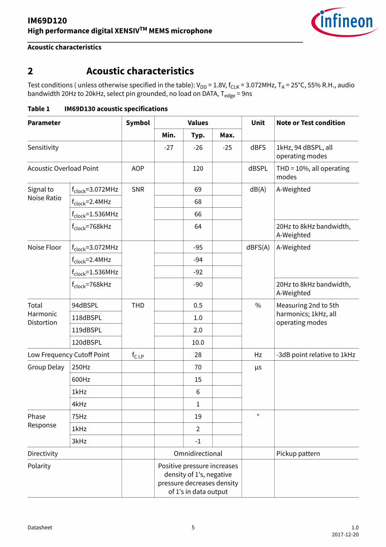
2 Acoustic characteristicsTest conditions ( unless otherwise specified in the table): VDD = 1.8V, fCLK = 3.072MHz, TA = 25°C, 55% R.H., audiobandwidth 20Hz to 20kHz, select pin grounded, no load on DATA, Tedge = 9ns
Table 1 IM69D130 acoustic specifications
Parameter Symbol Values Unit Note or Test condition
Min. Typ. Max.
Sensitivity -27 -26 -25 dBFS 1kHz, 94 dBSPL, alloperating modes
Acoustic Overload Point AOP 120 dBSPL THD = 10%, all operatingmodes
Signal toNoise Ratio
fclock=3.072MHz SNR 69 dB(A) A-Weighted
fclock=2.4MHz 68
fclock=1.536MHz 66
fclock=768kHz 64 20Hz to 8kHz bandwidth,A-Weighted
Noise Floor fclock=3.072MHz -95 dBFS(A) A-Weighted
fclock=2.4MHz -94
fclock=1.536MHz -92
fclock=768kHz -90 20Hz to 8kHz bandwidth,A-Weighted
TotalHarmonicDistortion
94dBSPL THD 0.5 % Measuring 2nd to 5thharmonics; 1kHz, alloperating modes
118dBSPL 1.0
119dBSPL 2.0
120dBSPL 10.0
Low Frequency Cutoff Point fC LP 28 Hz -3dB point relative to 1kHz
Group Delay 250Hz 70 µs
600Hz 15
1kHz 6
4kHz 1
PhaseResponse
75Hz 19 °
1kHz 2
3kHz -1
Directivity Omnidirectional Pickup pattern
Polarity Positive pressure increasesdensity of 1's, negative
pressure decreases densityof 1's in data output
IM69D120High performance digital XENSIVTM MEMS microphone
Acoustic characteristics
Datasheet 5 1.02017-12-20
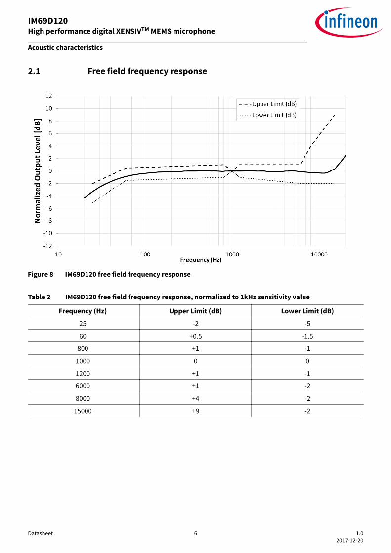
2.1 Free field frequency response
Figure 8 IM69D120 free field frequency response
Table 2 IM69D120 free field frequency response, normalized to 1kHz sensitivity value
Frequency (Hz) Upper Limit (dB) Lower Limit (dB)
25 -2 -5
60 +0.5 -1.5
800 +1 -1
1000 0 0
1200 +1 -1
6000 +1 -2
8000 +4 -2
15000 +9 -2
IM69D120High performance digital XENSIVTM MEMS microphone
Acoustic characteristics
Datasheet 6 1.02017-12-20
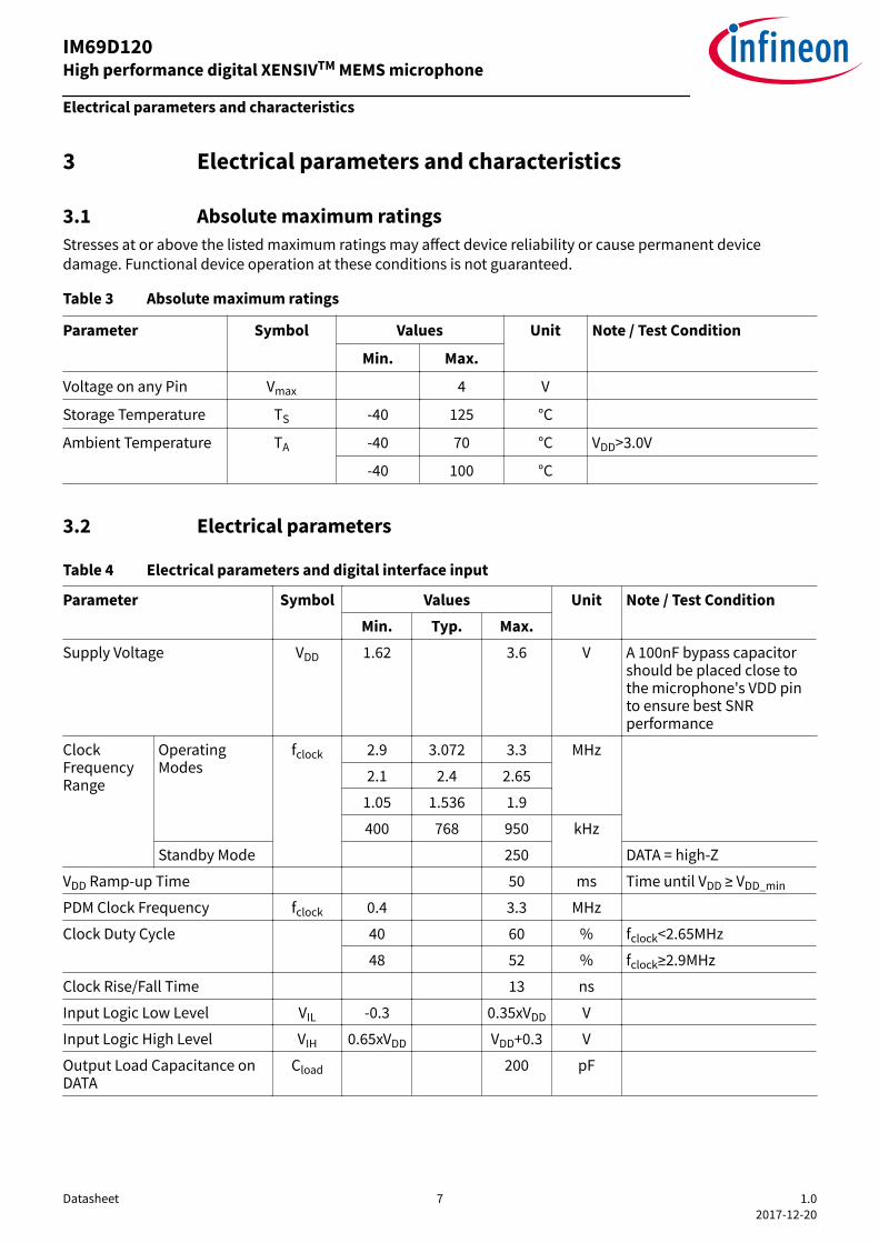
3 Electrical parameters and characteristics
3.1 Absolute maximum ratingsStresses at or above the listed maximum ratings may affect device reliability or cause permanent devicedamage. Functional device operation at these conditions is not guaranteed.
Table 3 Absolute maximum ratings
Parameter Symbol Values Unit Note / Test Condition
Min. Max.
Voltage on any Pin Vmax 4 V
Storage Temperature TS -40 125 °C
Ambient Temperature TA -40 70 °C VDD>3.0V
-40 100 °C
3.2 Electrical parameters
Table 4 Electrical parameters and digital interface input
Parameter Symbol Values Unit Note / Test ConditionMin. Typ. Max.
Supply Voltage VDD 1.62 3.6 V A 100nF bypass capacitorshould be placed close tothe microphone's VDD pinto ensure best SNRperformance
ClockFrequencyRange
OperatingModes
fclock 2.9 3.072 3.3 MHz
2.1 2.4 2.65
1.05 1.536 1.9
400 768 950 kHz
Standby Mode 250 DATA = high-Z
VDD Ramp-up Time 50 ms Time until VDD ≥ VDD_min
PDM Clock Frequency fclock 0.4 3.3 MHz
Clock Duty Cycle 40 60 % fclock<2.65MHz
48 52 % fclock≥2.9MHz
Clock Rise/Fall Time 13 ns
Input Logic Low Level VIL -0.3 0.35xVDD V
Input Logic High Level VIH 0.65xVDD VDD+0.3 V
Output Load Capacitance onDATA
Cload 200 pF
IM69D120High performance digital XENSIVTM MEMS microphone
Electrical parameters and characteristics
Datasheet 7 1.02017-12-20
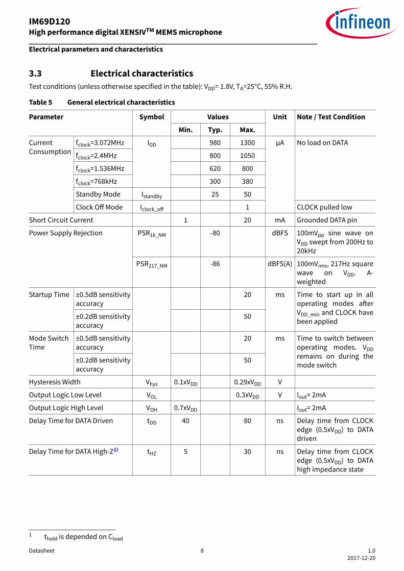
3.3 Electrical characteristicsTest conditions (unless otherwise specified in the table): VDD= 1.8V, TA=25°C, 55% R.H.
Table 5 General electrical characteristics
Parameter Symbol Values Unit Note / Test Condition
Min. Typ. Max.
CurrentConsumption
fclock=3.072MHz IDD 980 1300 μA No load on DATA
fclock=2.4MHz 800 1050
fclock=1.536MHz 620 800
fclock=768kHz 300 380
Standby Mode Istandby 25 50
Clock Off Mode Iclock_off 1 CLOCK pulled low
Short Circuit Current 1 20 mA Grounded DATA pin
Power Supply Rejection PSR1k_NM -80 dBFS 100mVpp sine wave onVDD swept from 200Hz to20kHz
PSR217_NM -86 dBFS(A) 100mVrms, 217Hz squarewave on VDD. A-weighted
Startup Time ±0.5dB sensitivityaccuracy
20 ms Time to start up in alloperating modes afterVDD_min and CLOCK havebeen applied
±0.2dB sensitivityaccuracy
50
Mode SwitchTime
±0.5dB sensitivityaccuracy
20 ms Time to switch betweenoperating modes. VDDremains on during themode switch
±0.2dB sensitivityaccuracy
50
Hysteresis Width Vhys 0.1xVDD 0.29xVDD V
Output Logic Low Level VOL 0.3xVDD V Iout= 2mA
Output Logic High Level VOH 0.7xVDD Iout= 2mA
Delay Time for DATA Driven tDD 40 80 ns Delay time from CLOCKedge (0.5xVDD) to DATAdriven
Delay Time for DATA High-Z1) tHZ 5 30 ns Delay time from CLOCKedge (0.5xVDD) to DATAhigh impedance state
1 thold is depended on Cload
IM69D120High performance digital XENSIVTM MEMS microphone
Electrical parameters and characteristics
Datasheet 8 1.02017-12-20
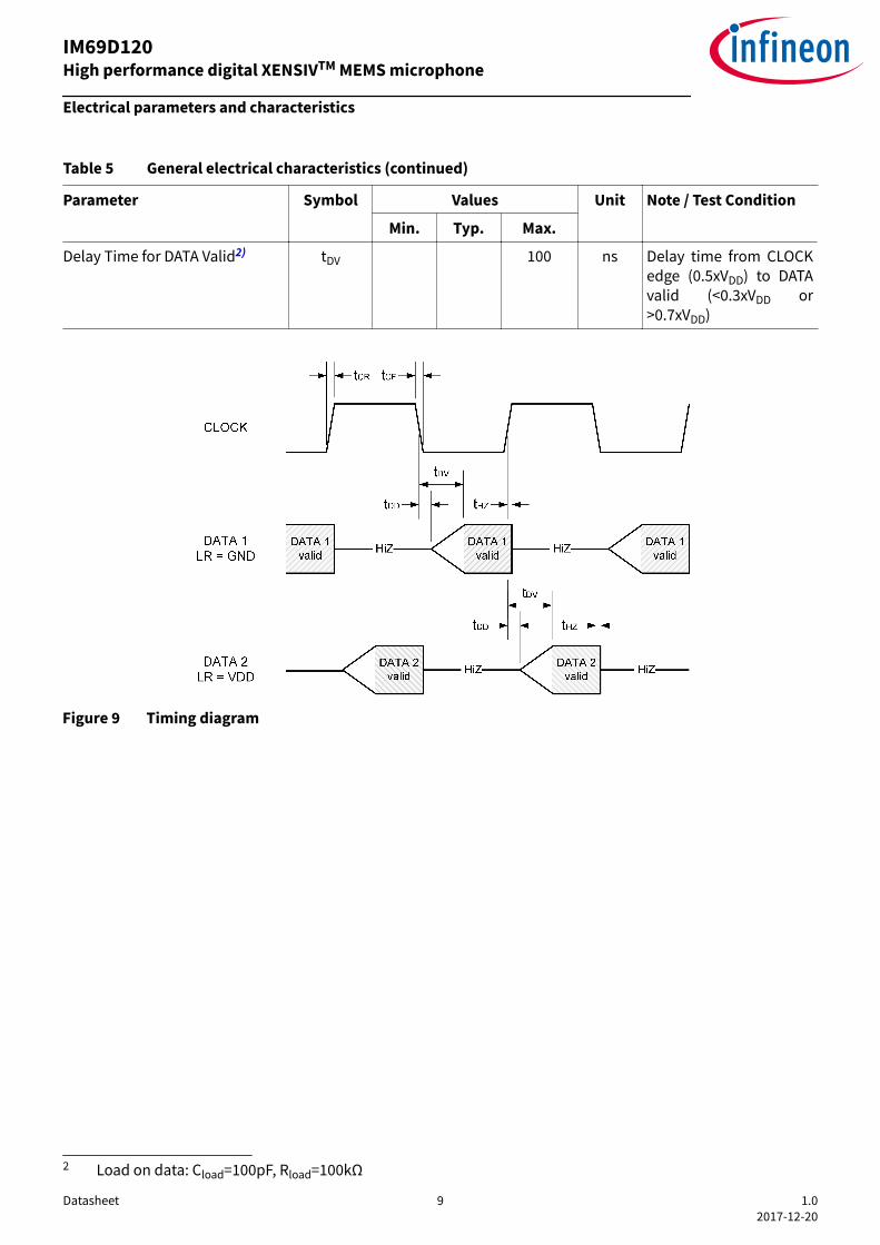
Table 5 General electrical characteristics (continued)
Parameter Symbol Values Unit Note / Test Condition
Min. Typ. Max.
Delay Time for DATA Valid2) tDV 100 ns Delay time from CLOCKedge (0.5xVDD) to DATAvalid (<0.3xVDD or>0.7xVDD)
Figure 9 Timing diagram
2 Load on data: Cload=100pF, Rload=100kΩ
IM69D120High performance digital XENSIVTM MEMS microphone
Electrical parameters and characteristics
Datasheet 9 1.02017-12-20
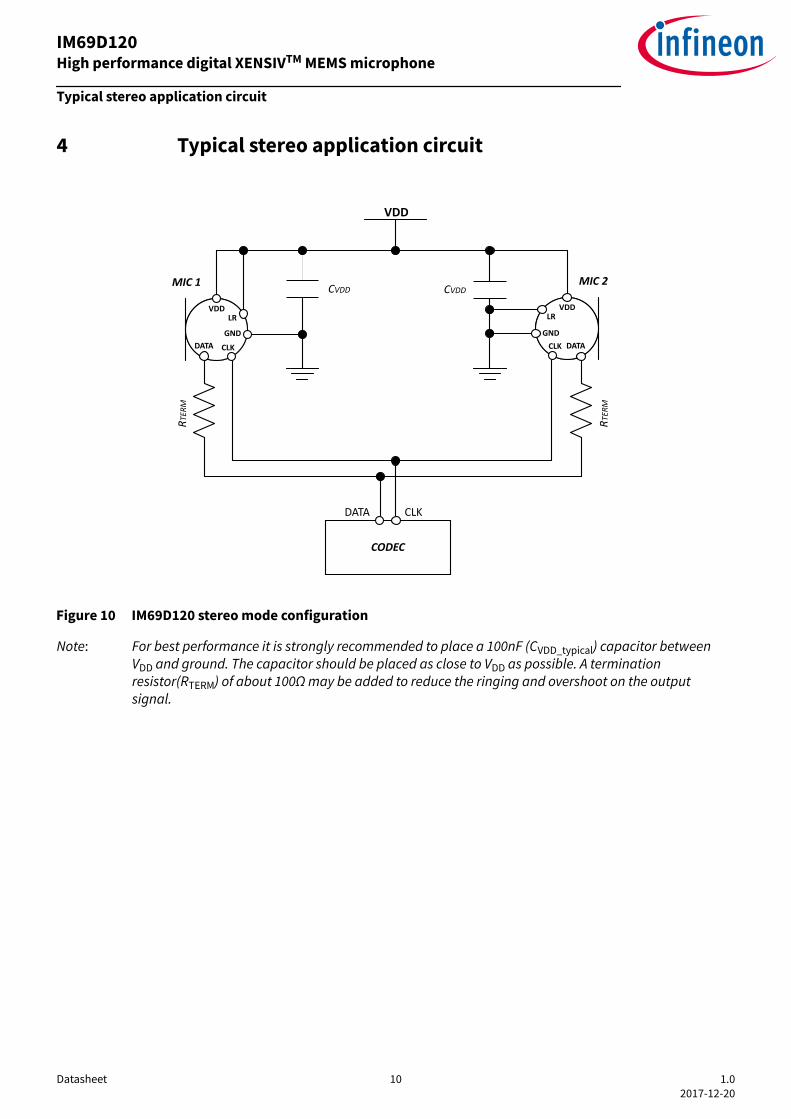
4 Typical stereo application circuit
VDD
RTER
M
RTER
M
CVDD CVDD
CLKDATA
CODEC
MIC 1 MIC 2
VDD VDD
GND GNDCLK CLK DATADATA
LRLR
Figure 10 IM69D120 stereo mode configuration
Note: For best performance it is strongly recommended to place a 100nF (CVDD_typical) capacitor betweenVDD and ground. The capacitor should be placed as close to VDD as possible. A terminationresistor(RTERM) of about 100Ω may be added to reduce the ringing and overshoot on the outputsignal.
IM69D120High performance digital XENSIVTM MEMS microphone
Typical stereo application circuit
Datasheet 10 1.02017-12-20

5 Reliability specificationsThe microphone sensitivity after stress must deviate by no more than 3dB from the initial value.
Table 6 Reliability tests
Test Test Condition Standard
Vibration 20Hz to 2000Hz with a peakacceleration of 20g in X, Y, and Z for4 minutes each, total 4 cycles
MIL-STD-883J
High Temperature Storage Ta=+125°C, 1000 hours JESD22 A-103E
Low Temperature Storage Ta=-40°C, 1000 hours JESD22-A119A
High Temperature Operation Ta=+125°C, VDD=2.5V, 1000 hours JESD22 A-108D
Cold Temperature Operation Ta=-40°C, VDD=3.2V, 1000 hours JESD22 A-108D
Temperature/Humidity Bias Ta=+85°C, R.H = 85%, VDD=3.2V,1000 hours
JESD22-A101D
Mechanical Shock 10000g/0.1msec direction ±x,y,z, 5shocks in each direction, 30 shocksin total
IEC 60068-2-27
Thermal cycle 1000 cycles, -40°C to +125°C, 30minutes per cycle
JESD22.A104E
Reflow Solder 3 reflow cycles, peak temperature =+260°C
IPC-JEDEC J-STD-020D-01
ESD-SLT 3 contact discharges of ±8kV to lidwhile Vdd and fclock are suppliedaccording to the operationalmodes; (Vdd and fclock ground isseparated from earth ground)
IEC-61000-4-2
ESD-HBM 1 pulse of ±2kV between all I/O pincombinations
JS001
Latch up Trigger current from ±150mA JESD 78E
IM69D120High performance digital XENSIVTM MEMS microphone
Reliability specifications
Datasheet 11 1.02017-12-20
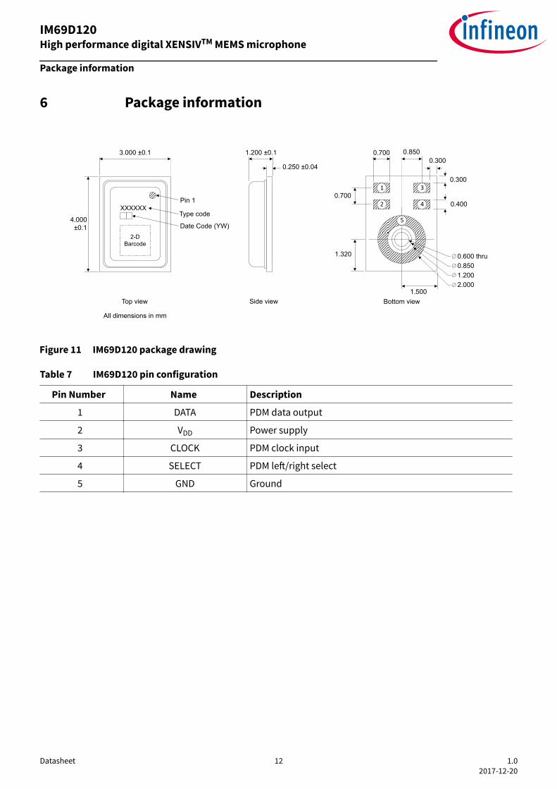
6 Package information
0.8500.7000.300
0.300
1.320
0.700
1.5002.0001.2000.850
1.200 ±0.1
0.250 ±0.04
3.000 ±0.1
4.000±0.1
All dimensions in mm
0.600 thru
0.400
1
2
3
5
4XXXXXXPin 1
2-D Barcode
Top view Side view Bottom view
Type code
Date Code (YW)
Figure 11 IM69D120 package drawing
Table 7 IM69D120 pin configuration
Pin Number Name Description
1 DATA PDM data output
2 VDD Power supply
3 CLOCK PDM clock input
4 SELECT PDM left/right select
5 GND Ground
IM69D120High performance digital XENSIVTM MEMS microphone
Package information
Datasheet 12 1.02017-12-20

7 Footprint and stencil recommendationThe acoustic port hole diameter in the PCB should be larger than the acoustic port hole diameter of the MEMSMicrophone to ensure optimal performance. A PCB sound port size of radius 0.4 mm (diameter 0.8mm) isrecommended.The board pad and stencil aperture recommendations shown in Figure 12 are based on Solder Mask Defined(SMD) pads. The specific design rules of the board manufacturer should be considered for individual designoptimizations or adaptations.
Figure 12 IM69D120 footprint and stencil recommendation
Note: Dimensions are in millimeters unless otherwise specified
IM69D120High performance digital XENSIVTM MEMS microphone
Footprint and stencil recommendation
Datasheet 13 1.02017-12-20
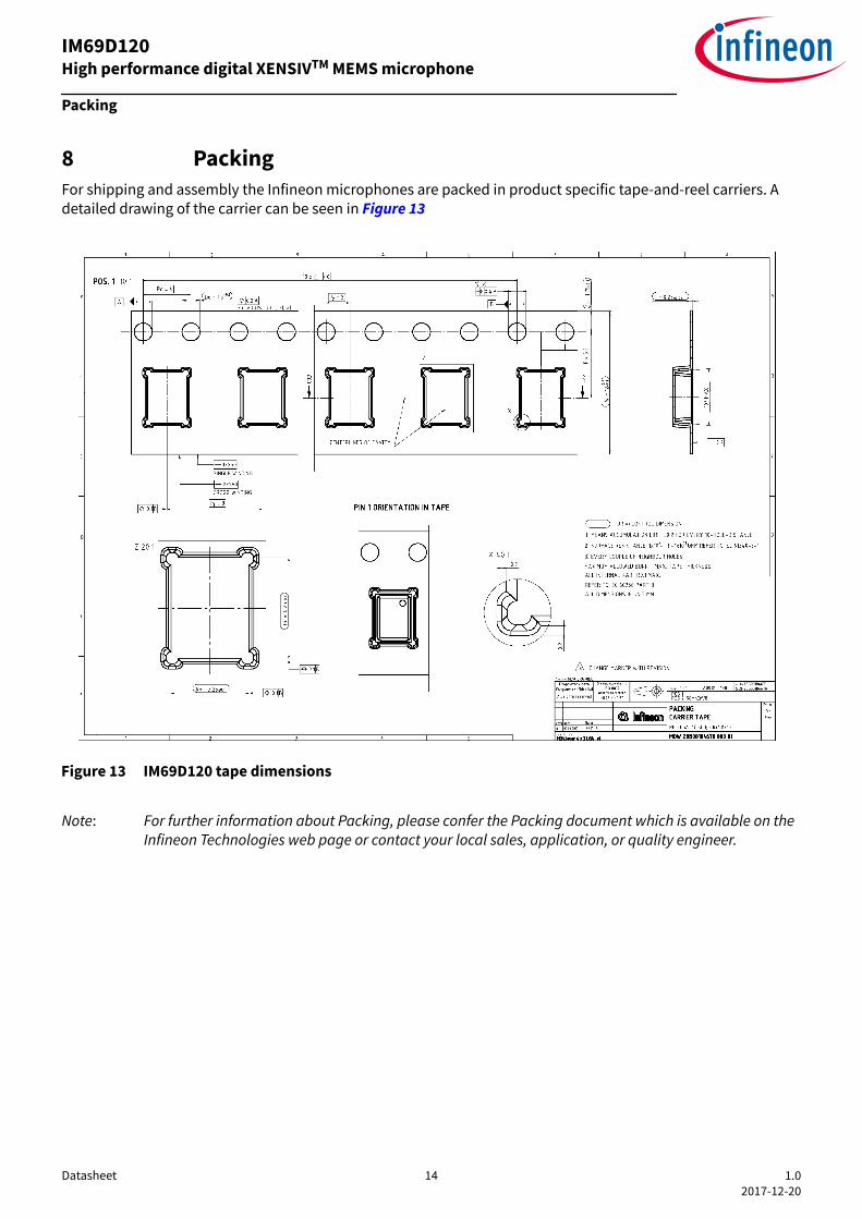
8 PackingFor shipping and assembly the Infineon microphones are packed in product specific tape-and-reel carriers. Adetailed drawing of the carrier can be seen in Figure 13
Figure 13 IM69D120 tape dimensions
Note: For further information about Packing, please confer the Packing document which is available on theInfineon Technologies web page or contact your local sales, application, or quality engineer.
IM69D120High performance digital XENSIVTM MEMS microphone
Packing
Datasheet 14 1.02017-12-20
Revision historyDocumentversion
Date ofrelease
Description of changes
1.0 20.12.2017 Initial datasheet
IM69D120High performance digital XENSIVTM MEMS microphone
Revision history
Datasheet 15 1.02017-12-20
TrademarksAll referenced product or service names and trademarks are the property of their respective owners.
Edition 2017-12-20Published byInfineon Technologies AG81726 Munich, Germany © 2017 Infineon Technologies AGAll Rights Reserved. Do you have a question about anyaspect of this document?Email: [email protected] Document referenceIFX-tgc1507128354827
IMPORTANT NOTICEThe information given in this document shall in noevent be regarded as a guarantee of conditions orcharacteristics (“Beschaffenheitsgarantie”) .With respect to any examples, hints or any typical valuesstated herein and/or any information regarding theapplication of the product, Infineon Technologieshereby disclaims any and all warranties and liabilities ofany kind, including without limitation warranties ofnon-infringement of intellectual property rights of anythird party.In addition, any information given in this document issubject to customer’s compliance with its obligationsstated in this document and any applicable legalrequirements, norms and standards concerningcustomer’s products and any use of the product ofInfineon Technologies in customer’s applications.The data contained in this document is exclusivelyintended for technically trained staff. It is theresponsibility of customer’s technical departments toevaluate the suitability of the product for the intendedapplication and the completeness of the productinformation given in this document with respect to suchapplication.
WARNINGSDue to technical requirements products may containdangerous substances. For information on the typesin question please contact your nearest InfineonTechnologies office.Except as otherwise explicitly approved by InfineonTechnologies in a written document signed byauthorized representatives of Infineon Technologies,Infineon Technologies’ products may not be used inany applications where a failure of the product orany consequences of the use thereof can reasonablybe expected to result in personal injury