Embed Size (px)
Citation preview
Solutions for Materials Preparation, Testing and Analysis
By: Matthias Hoffman, Kai Akatsu, & George Vander Voort
Image Processing in the Material’s Laboratory!
Published by Buehler, a division of Illinois Tool Works Volume 1, Issue 4
Video/Digital ImagingFor many years, metallographers have documented images. Typically, they are acquired using light optical microscopes, stere microscopes, macro lenses and scanning electron microscopes (SEM). Photography was, and still is, the most common way to obtain micro- and macrostructural images for the materials laboratory. At first, glass plates, then sheet film and 35mm film formats were used to accomplish this task. Since the 1960’s, Polaroid instant films have largely replaced wet-processed films. Polaroid film is expensive and duplicates of the original prints are rather costly. To generate reports, photomicrographs have to be manually cropped and pasted, a rather time consuming task.
Wet processed films produce the highest quality images, with best permanence, easily duplicated but the process is labor intensive and negative storage (and subsequent retrieval) is a problem. Instant films, which do not require a darkroom technician, offer speed and convenience. The savings in processing time and labor is offset somewhat by high film costs, waste, and the greater expense when multiple prints are required. Further, image quality of some instant films is noticeably inferior. Color instant films are plagued with reciprocity failures, i.e., inability to generate true colors unless the exposure time is carefully controlled. The newer 64T film has solved this problem.
The revolutionary progress in computer and video technology has created a definitive trend toward electronic image acquisition. These images can be used in other software applications such as word processors or desktop publishing programs allowing for faster report generation.
Today’s developments aim to match the established photographic quality standards in the materials laboratory with video/digital microscopy and archiving technologies. In fact, ASTM (American Society for Testing and Materials) Committee E-4 on Metallographyis developing guidelines for video microscopy. The term “Photo Realistic Imaging” is commonly used to describe the desired imagequality utilizing video microscopy techniques. The final quality of electronicallygenerated images depends on a number of variables: the image input device, frame grabber, computer system and printing device. All the above electronic hardware components have to be matched up properly to achieve the desired results of creating photo realistic images. With the ability to acquire images electronically, the need for image handling logistics is evident.
What is Video/Digital imaging? Video/digital imaging includes a number of operations: image capture (wide range of sources), image processing, storage, permanent archiving and image retrieval. A logical organizational structure needs to be in place to perform these tasks.
Image CaptureThis term describes acquisition of an image by means of a camera and frame grabber. Because of the many choices of camera types, a video microscopy system must be flexible. Analog CCD (Charged-Coupled Device) cameras, both black and white and color, are most frequently used. Component video (Y/C or S-Video) and composite video signals and a number of color video standards such as NTSC,PAL and SECAM need to be supported. Images acquired in the materials laboratory are optimized in real time by adjusting brightness, contrast, and color saturation. The analog output camera signal is then digitized utilizing an analog frame grabber board. Various PC-compatible image file formats and compression algorithms are commonly used, such as TIFF, BMP, TGA, DBA, PCX, JPEG and many others. The gamma factor (ratio of input signal to brightness level) can be adjusted on a captured image. Video cameras are rated by resolution expressed in horizontal video lines. This rating system provides a comparison between cameras describing the capability of resolving features under certain test conditions. Some available cameras provide resolutions of 700 H (Horizontal) lines or higher.
Digital output CCD camera technology requires digital frame grabber boards. Today, high-resolution digital cameras are available with real-time imaging capability. This technology however is very costly, therefore limiting the use of these cameras. However, digital video technology is expected to become less expensive in the future.
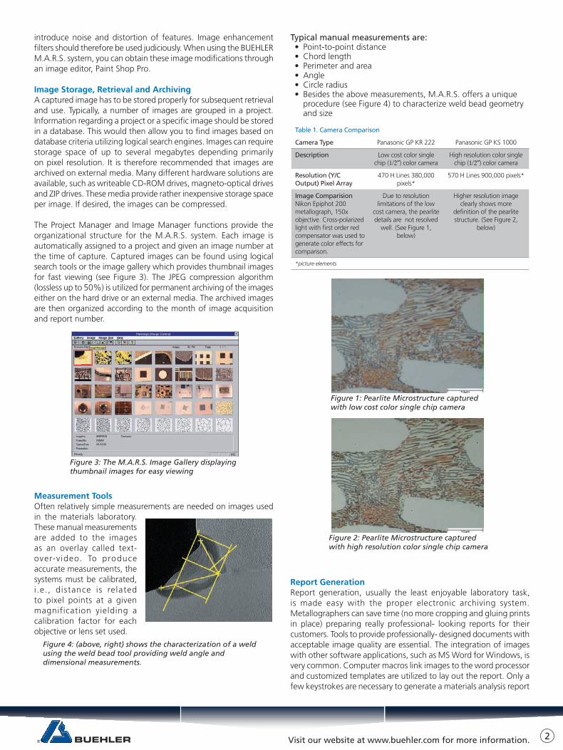
The influence of increased horizontal line camera resolution is illustrated in Figures 1 and 2 (facing page) which show the microstructure of a pearlitic steel captured using two different cameras. Table 1 summarizes the capture conditions of the images discussed above.
Image EnhancementSimple image enhancements are brightness, contrast, color saturation and gamma factor adjustments. More complex image enhancements can be performed with mathematical processing filters. These filters alter the spatial characteristics of the image. Filters have been developed to both enhance and soften edges, contours and fine detail. Excessive use of these image filters can
Visit our website at www.buehler.com for more information.
introduce noise and distortion of features. Image enhancement filters should therefore be used judiciously. When using the BUEHLER M.A.R.S. system, you can obtain these image modifications through an image editor, Paint Shop Pro.
Image Storage, Retrieval and ArchivingA captured image has to be stored properly for subsequent retrieval and use. Typically, a number of images are grouped in a project. Information regarding a project or a specific image should be stored in a database. This would then allow you to find images based on database criteria utilizing logical search engines. Images can require storage space of up to several megabytes depending primarily on pixel resolution. It is therefore recommended that images are archived on external media. Many different hardware solutions are available, such as writeable CD-ROM drives, magneto-optical drives and ZIP drives. These media provide rather inexpensive storage space per image. If desired, the images can be compressed.
The Project Manager and Image Manager functions provide the organizational structure for the M.A.R.S. system. Each image is automatically assigned to a project and given an image number at the time of capture. Captured images can be found using logical search tools or the image gallery which provides thumbnail images for fast viewing (see Figure 3). The JPEG compression algorithm (lossless up to 50%) is utilized for permanent archiving of the images either on the hard drive or an external media. The archived images are then organized according to the month of image acquisition and report number.
Measurement ToolsOften relatively simple measurements are needed on images used in the materials laboratory. These manual measurements are added to the images as an overlay called text-over-v ideo. To produce accurate measurements, the systems must be calibrated, i .e., distance is related to pixel points at a given magnification yielding a calibration factor for each objective or lens set used.
Typical manual measurements are:• Point-to-point distance• Chord length• Perimeter and area• Angle• Circle radius• Besides the above measurements, M.A.R.S. offers a unique
procedure (see Figure 4) to characterize weld bead geometry and size
Report GenerationReport generation, usually the least enjoyable laboratory task, is made easy with the proper electronic archiving system. Metallographers can save time (no more cropping and gluing prints in place) preparing really professional- looking reports for their customers. Tools to provide professionally- designed documents with acceptable image quality are essential. The integration of images with other software applications, such as MS Word for Windows, is very common. Computer macros link images to the word processor and customized templates are utilized to lay out the report. Only a few keystrokes are necessary to generate a materials analysis report
Figure 3: The M.A.R.S. Image Gallery displaying thumbnail images for easy viewing
Figure 4: (above, right) shows the characterization of a weldusing the weld bead tool providing weld angle and dimensional measurements.
Table 1. Camera Comparison
Camera Type Panasonic GP KR 222 Panasonic GP KS 1000
Description Low cost color single chip (1/2″) color camera
High resolution color single chip (1/2″) color camera
Resolution (Y/C Output) Pixel Array
470 H Lines 380,000 pixels*
570 H Lines 900,000 pixels*
Image ComparisionNikon Epiphot 200 metallograph, 150x objective. Cross-polarized light with first order red compensator was used to generate color effects for comparison.
Due to resolution limitations of the low
cost camera, the pearlite details are not resolved
well. (See Figure 1, below)
Higher resolution image clearly shows more
definition of the pearlite structure. (See Figure 2,
below)
*picture elements
Figure 1: Pearlite Microstructure captured with low cost color single chip camera
Figure 2: Pearlite Microstructure captured with high resolution color single chip camera
2

BUEHLER Worldwide Headquarters41 Waukegan RoadLake Bluff, Illinois 60044-1699 USAP: (847) 295-6500www.buehler.com | [email protected]
BUEHLER [email protected]
BUEHLER [email protected]
BUEHLER United [email protected]
BUEHLER [email protected]
BUEHLER [email protected]
BUEHLER [email protected]
BUEHLER [email protected]
Connect with us:
© 2015 BUEHLER, a division of Illinois Tool Works Inc. Printed in U.S.A. FN01022_0615
in minutes or less. Figure 5 shows a typical materials analysis report generated with the BUEHLER M.A.R.S. system utilizing templates in MS Word for Windows.
ConclusionThe materials laboratory is undergoing many changes due to the increased efforts to provide automation of all possible processes. Video capture and archiving forms an essential link in the overall lab automation process. We are living in a fast moving world demanding rapid exchange of information with customers, vendors and interest groups. Documented images can be shared by means of E-mail and the World Wide Web. As computer and video technology continuesto expand, the trend towards high resolution video systems will prevail. The ability to provide high resolution “photo realistic” images in a cost effective manner will largely replace photography in the materials laboratory.
Look for future issues of Tech-Notes for information on image resolution and printing technology.
AcknowledgmentsThe technical input of Alan Woodman is greatly appreciated by the authors.
Tech-TipsQuestion: What are critical parameters to ensure proper mounting results using castable epoxy resins?
Answer: A number of variables have to be considered and addressed to obtain successful epoxy mounts: specimen preparation before mounting, measuring the resin and hardener, mixing, shelf life and curing temperatures. Specimens to be mounted must be absolutely dry. This is especially important with porous specimens. Appropriatecleaning and drying of the specimens is needed to guarantee
proper adhesion and curing of the mounting material. Castable epoxy mounting resins have two components, the epoxy resin and hardener.Unlike acrylic resin systems, the proportioning of resin and hardener has to be controlled more tightly. The resin and hardener amounts should be determined by weight rather than by volume. The resin-to-hardener ratio is 5:1 for EPO-KWICK® and EPOXIDE resins, and 5:2 for the EPO-THIN® system. Proper, homogeneous mixing is typicallyachieved in 60 seconds of time. Do not stir too vigorously! It is not recommended to mix batches larger than 100g. Larger amounts may develop too much exothermic heat causing rapid gas generation and accelerated curing. It is recommended to tilt the mounting cup while stirring the resin mixture allowing trapped air bubbles to raise to thesurface. Remaining air bubbles tend to attach themselves to the edge of the specimen leading to preparation problems. Epoxy resins typically have a shelf life of one year. In particular, the hardener is chemically altered by exposure to oxygen. Curing times often increase as a result of aging of the hardener. This can be compensated by putting the mounts in a laboratory oven to accelerate the curing process (60 minutes at 50°C). Mounts are known to become yellow with the use of an aged hardener. Refrigeration helps to prolong the shelf life of the hardener. The guidelines given here are for roomtemperatures around 20°C (70 F). An increase of 10°C (18 F) could potentially decrease the curing time by almost a factor of two causing shrinkage and cracking problems due to the accelerated curing.
Question: What is the reason for offering different epoxy resins?
Answer: Certain specimens might be sensitive to the maximum peak curing temperature (such as polymers) or may require lower viscosity to infiltrate pores and voids.
The table below shows a summary of the castable epoxy resin systems offered by BUEHLER.
Resin Type Hardener Ratio
(by weight)
Curing Time Peak
Temp.
Applications
EPO-KWICKfi 5:1 45-60 min. 182 F If relatively fast curing time is needed
EPOXIDE 5:1 8 hours 82 F If low curing temperature is required
EPO-THINfi 5:2 12-20 hrs. (2 hours oven curedat 80 C for 60 min.)
82 F If low viscosity is required to infiltrate pores
EPO-COLOR 5:1 1-2 hours 175 F Designed to create color contrast of voids.
Figure 5: A typical materials analysis report generated with the MS Word template.


![· Series Photomicrographic Systems [For EPIPHOT 200] Nikon's FX-III Series photomicro- graphic systems employ the swing- out beam splitter system which directs 1000/0 of the illumination](https://img.pdfslide.net/doc/110x75/5b9e3c2109d3f2a4348d6778/-series-photomicrographic-systems-for-epiphot-200-nikons-fx-iii-series-photomicro-.jpg)