Embed Size (px)
Citation preview

IMIA-WGP18 (01)E
IMIA Meeting 2001, Sydney
Tunnel Boring Machine (TBM) applications in softground conditions
Authors: Louis Wassmer, Oscar Treceno, Enrico Andreossi, Swiss Re

2
IMIA Paper
Tunnel Boring Machine applications (TBM/SM) in softground conditions.
Pages
1 Executive Summary 3
2 Introduction 3
3.1 Soft soil basic classification 53.2 Methods of preliminary investigation 53.3 Consequences for construction 6
4.1 TBM/SM Concept 74.2 Shield Machine (SM) types 10
5 Risk analysis5.1 Project environment 115.2 Characteristics of tunnel works 125.3 Parties involved 125.4 List of possible failures 135.5 Third party liability (TPL) 15
6.1 Loss experience 166.2 Case study A) Wastewater project Alpha 176.3 Case Study B) Metro project Beta 196.4 Conclusions on cases studied 22
7 Risk transfer7.1 Insurance 227.2 Wording 237.3 Material change of risk 247.4 Loss settlement 257.5 Special tunnelling clauses 267.6 Others recommendations 27
8 General conclusions 29
9 Annexes 30

���([HFXWLYH�VXPPDU\6RPH�PDMRU�DVSHFWV�LQIOXHQFLQJ�WXQQHO�FRQVWUXFWLRQ�LQ�VRIW�VRLOV�KDYH�FKDQJHGFRQVLGHUDEO\�GXULQJ�WKLV�ODVW�GHFDGH��,Q�WXUQ��ERWK�LQVXUHUV�DQG�UHLQVXUHUV�DUH�QRZ�LQ�DYHU\�GHOLFDWH�VLWXDWLRQ�UHJDUGLQJ�WKH�RXWFRPH�7KH�ZRUOGZLGH�GHPDQG�IRU�XQGHUJURXQG�IDFLOLWLHV�LV�JURZLQJ�DW�D�UDSLG�UDWH��DQG�DVXEVWDQWLDO�QXPEHU�RI�WKHVH�SURMHFWV�DUH�ORFDWHG�LQ�FLWLHV�ZKHUH�JURXQG�FRQGLWLRQV�DUH�QRWRSWLPDO�*LYHQ�WKH�DGYDQFHV�LQ�WXQQHOOLQJ�WHFKQRORJ\�WRGD\��WXQQHOV�FDQ�EH�H[FDYDWHG�LQ�YLUWXDOO\DOO�W\SHV�RI�VRLO�DQG�HQYLURQPHQW��EXW�WKHUH�DUH�VWLOO�QXPHURXV�XQNQRZQ�SDUDPHWHUV��2QHRI�WKH�PRVW�LPSRUWDQW�LV�WKH�NQRZOHGJH�RI�WKH�JURXQG�WKURXJK�ZKLFK�WKH�WXQQHO�ZLOO�EHURXWHG��%HIRUH�WKH�FRQVWUXFWLRQ�VWDUWV��D�QXPEHU�RI�DVVXPSWLRQV�UHJDUGLQJ�JHRORJ\�K\GURORJ\��VRLO�FKDUDFWHULVWLFV��DQG�HYHQ�WKH�VXUURXQGLQJV�PXVW�EH�PDGH��7KH�OHYHO�RIDFFXUDF\�RI�WKHVH�DVVXPSWLRQV�KDV�D�GLUHFW�LPSDFW�RQ�WKH�ILQDO�H[SRVXUH�7KHUH�LV�DOVR�D�FOHDU�WUHQG�WR�VKLIW�WKH�EXUGHQ�RI�JHRORJLFDO�ULVN�IURP�WKH�SULQFLSDO�WR�WKHFRQVWUXFWRU�DQG�XOWLPDWHO\�WR�WKH�LQVXUHUV�UHLQVXUHUV��SURGXFLQJ�D�FOHDU�LQFUHDVH�RI�WKHILQDO�H[SRVXUH�7KH�ZRUGLQJV�HPSOR\HG�DUH�RIWHQ�QRW�LGHDOO\�DGDSWHG�WR�WKH�FKDUDFWHULVWLFV�RI�WXQQHOOLQJSURMHFWV�EHFDXVH�RI�WKH�RYHUODSSLQJ�RI�ORVV�PLWLJDWLRQ��UHSDLU�ZRUNV��DQG�EHWWHUPHQW�+HQFH��WKH\�PDNH�ORVV�VHWWOHPHQWV�LQ�WXQQHOOLQJ�KLJKO\�GLIILFXOW�/DVW�EXW�QRW�OHDVW��WKLUG�SDUWLHV�KDYH�EHFRPH�PXFK�PRUH�FODLPV�FRQVFLRXV��'XH�WR�WKHSUR[LPLW\�RI�WKH�WXQQHO�WR�DERYH�JURXQG�SURSHUWLHV�¤�FOHDUO\�WKH�FDVH�LQ�FLWLHV�¤�DQG�LQOLJKW�RI�WKLV�WUHQG��D�PDMRU�SRUWLRQ�RI�WKH�SUHPLXP�PXVW�QRZ�EH�GHGLFDWHG�WR�WKH�73/SROLF\�VHFWLRQ�7KH�FRPELQHG�HIIHFW�RI�DOO�WKHVH�HOHPHQWV�KDV�OHG�WR�WKH�GHWHULRUDWLRQ�RI�WKH�ORVV�UDWLR�LQUHFHQW�\HDUV��DQG�KHQFH��WKH�QHHG�IRU�LQ�GHSWK�VWXGLHV�RI�WKLV�VLWXDWLRQ����,QWURGXFWLRQ�,Q�FRQWUDVW�WR�PDQ\�RWKHU�FLYLO�HQJLQHHULQJ�SURFHVVHV��WXQQHO�FRQVWUXFWLRQ�SKDVHVFXUUHQWO\�XVHG�DUH�SULQFLSDOO\�LGHQWLFDO�RU�VLPLODU�WR�WKRVH�HPSOR\HG�LQ�WKH�ODVW�FHQWXU\�EXW�WKH�PHWKRGV�DUH�QRW��7KH�PDMRU�FKDQJHV�ZKLFK�KDYH�RFFXUUHG�SULPDULO\�LQYROYH�PRUHVWULQJHQW�H[WHUQDO�LQIOXHQFHV�DQG�WKH�DGYHQW�RI�QHZ�GULOOLQJ�DQG�H[FDYDWLRQ�WHFKQRORJLHV�7XQQHOOLQJ�SURMHFWV�PXVW�QRZ�FRQVLGHU�QXPHURXV�XQGHUO\LQJ�SROLWLFDO�DQG�HQYLURQPHQWDOIDFWRUV�ZKLFK�DGG�WR�WKH�RYHUDOO�FRPSOH[LW\�RI�D�JLYHQ�SURMHFW��$UJXDEO\�RQH�RI�WKH�PRVWGHPDQGLQJ�FLYLO�HQJLQHHULQJ�GLVFLSOLQHV��WXQQHOOLQJ�UHIOHFWV�D�ERUGHUOLQH�VLWXDWLRQEHWZHHQ�VDIHW\�DQG�HFRQRP\�7KH�WXQQHO�LWVHOI�FDQ�QR�ORQJHU�EH�FRQVLGHUHG�DV�DQ�DXWRQRPRXV�FLYLO�ZRUNV�HQWLW\�5DWKHU��LW�PXVW�EH�YLHZHG�ZLWKLQ�WKH�FRQWH[W�RI�LWV�LQWHJUDWLRQ�LQ�H[LVWLQJ�WUDQVSRUWDWLRQLQIUDVWUXFWXUHV�DQG�KRZ�LW�ZLOO�VXEVHTXHQWO\�FRPSO\�ZLWK�SURVSHFWLYH�QHWZRUN�FRQFHSWV�
4
Generally, a tunnelling project can be divided into the following five constructionphases.
Once the tunnel’s overall purpose is defined, the environment and surrounding regionsare evaluated to arrive at a rough decision regarding the tunnel’s alignment or routing.These decisions depend on the scope of the tunnel, and reflect the influence of factorssuch as governmental regulations, restrictions, accessibility, cost parameters, projectdeadlines, and possible time restraints.
The second phase involves the evaluation of different design parameters (e.g.diameter,lining) and the respective construction method to be employed (e.g. conventional,staged or sequential excavation coupled with the use of shotcrete lining, hybridtechniques, tunnel boring machine (TBM).
Once the specific construction technique is selected, the project details are thenanalysed in depth. During this phase, specialists, suppliers and possibly contractors areinvolved to arrive at final project specifications.
Phase four involves the actual excavation and construction. Since this phase is ofcentral importance for the underwriter, additional factors also come into play, i.e. soilcomposition of the tunnelling site, stabilisation safeguards for the excavation whichinclude shotcrete linings, anchor, rock bolts, wire mesh, provisional or permanentsection linings according to the respective technique. The loading and discharge of theexcavated material into a deposit or silo for future use is also a decisive logisticsfactor.
The final phase is devoted to the finishing and installation work which is oftenperformed by a different contractor adapting the tunnel to its ultimate use (e.g.railroad,road, sewage, water supply) Technical installations including lighting, signalling, firedetection and safety systems and equipment are provided after construction iscompleted.
At the beginning of the last century, geological factors were predominantly responsiblefor determining the overall feasibility of a tunnel project, the determinative factor beingthe rock or ground conditions. Consequently, the state of the art in engineering at thetime limited construction to shorter tunnels.
Tunnels are now built where they are needed or specified. The political and particularlyenvironmental considerations have become vital factors over the years, in some casesvying in importance with engineering and geological factors. The tunnel’s integration inexisting transportation networks is also a decisive factor. Due to these restraints, tunnelsare often routed through ground compositions which are less than ideal. Geologicalaspects have assumed a secondary importance and available technology is expected tocope with them.
Today, there are many different techniques available, but certainly one of the majortechnological breakthroughs is the tunnel boring machine (TBM) for fully mechanisedtunnelling, comprising excavation, support, lining, and transportation of excavationmaterial.

5
3.1 Basic soil classification
Ground categories are broken down roughly according to the following table:
Hard rock Soft rock Soft soil(without cohesion)
Soft soil(with cohesion)
DolomiteLimestoneSandstoneGraniteBasaltLavaGneissQuartzite
MarlHard claySlateDolomite
Sand, fine gravel,gravel,coarse–grained,stonesFlowing ground =soil with high watercontent.
Expansive orswelling groundsuch as clay-stones,anhydrite rock incontact with water,silt
These soil classifications are done according to national / international standards andrecommendations (e.g. DIN 18196 soil classification for construction purposes)
Only the soft soil categories will be considered in this paper
Soft soils are, contrarily to igneous or metamorphous rock the result of sedimentation andmay be roughly classified in two types of behaviour :
- Non-cohesive soils such as gravel and sand are unstable and will, if excavated, achievea surface inclined according to their internal friction angle. They are permeable andground water is subject to the hydrological flow laws.
- Cohesive soils such as silt and clay may for some time stand vertically, but threaten toshear off and are often highly compressible. Groundwater does not conform with thehydrological laws, but adheres to soil particles and can be removed only using specialpoint wells.
Generally, soft soils are unstable over a certain period and must be considered as lesspredictable than hard rock. Hence, adequately describing their behavioural propertiesrequires definition of many more parameters than in the case of hard rock.
Some of the primary analytical parameters include the following: grading curve, angle offriction, cohesion, deposit thickness, strength figures, plasticity, swelling behaviour,permeability, water bearing and water pressure, consistency, and relative density,liquefaction possibility.
The following technical data can be obtained from the cited geotechnical characteristicvalues and an overall assessment of the geological and hydrological conditions of thesubsoil, face stability, proposed face support measures, time lag between excavation andsecuring the subsoil, and deformation behaviour.

6
Geological chart with grouting profile
3.2 Methods of investigation
Knowledge of geotechnical conditions is the most important principle for the planning andexecuting a tunnelling project. Soil analysis requires time and expertise and normallyrequires 1% to 3% of the overall construction budget.
The preliminary assessment relies on existing documents, topographical maps andfeedback from previously constructed civil works in the vicinity to provide an overallevaluation of geological and hydrogeological conditions and is supplemented by furtherinvestigation as required. More precise information is required for the design phase, anddifferent investigation techniques are used:- Investigative boring and the respective core samples- Exploration and surface samples- Dynamic penetration tests, pressure probes- Mechanical borehole examinations (expansion tests)- Pump and water injection tests, exploratory tunnels or shafts
During construction, additional information is obtained along the tunnel or by additionalpilot tunnels. This provides a comparative analysis with anticipated ground conditions andis fundamental for subsequently adapting construction to relevant conditions, which is anongoing process during the entire project.
3.3 Consequences for Construction
Generally, tunnels built in soft ground are located in metropolitan areas. Their applicationsrange from utility tunnels linked to sewage systems, water transport systems or wider

7
diameter tunnels – mainly tunnels for highway (city by pass) rail or subways. Stability is acritical aspect of soft ground tunnels and safety measures must be implemented promptlyin time and distance from the excavation face so that the support structure is active.
The contractor requires highly detailed geological information, and additionalinvestigations are required if a clear assessment cannot be made.
Geological documentation should provide information on the following:- Ground structure with indication of material classification and homogeneity
(geological map, tables with measured factors)- Subterranean obstacles to be expected (e.g. boulders, blocks, erratic blocks,
underground structures, archaeological artefacts)- Groundwater conditions indicating the level, ground permeability, flow direction and
velocity, chemical values, hydrostatic pressure- Probable ground reaction after excavation- Possible use of excavated material, contamination possibility and degree, deposit
criteria, waste deposits above and underground- Vibration characteristics of the excavation method tend to lower the groundwater
table, creating settlements.
The respective construction method is determined by relevant geotechnical characteristicvalues and construction information. Tunnelling classes are then assigned over therouting length which identify the performance requirements per class and describe thelevel of technical difficulty.
Sometimes alternatives in sequence or construction method might be economically morefavourable. The proposal of alternative methods depends on the type of contract betweenthe principal and the construction company. However if an alternative method is adopted,the contractor must assume the full design responsibility.
4.1 Underlying concepts for Tunnel Boring Machine (TBM) / Shield Machine (SM)
In an effort to facilitate and automate tunnelling operations to some extent, the civilengineering industry began developing machines incorporating mechanisation andautomation practices similar to those employed in manufacturing processes. During thepast 25 years, the industry has continually improved their features and enhanced theirapplication ranges.
Generally speaking, tunnelling machines are circular, they either head the entire tunnelcross-section with a cutter head or cutting wheel full-face or in part segments by meansof suitable extraction equipment. During the excavation phase, the machine is movedforward either continuously or incrementally.
Both the TBM (hard rock applications) and SM (soft ground) fulfil the same purpose:- ensuring systematic and automated subsoil excavation;- providing an effective protection (the shield) for the labour force at the front ;- stabilising the tunnel through quickly closing of the support ring- transportation of the excavated material

8
In this paper, discussion is confined to shield machines (SM).An other limitation is regarding the so called micro-tunnelling techniques / pipe jacking(normally diameter < 3 metres), those techniques are gaining importance, neverthelessthey will not be treated in this paper.
The main constitutive items of a SM are the following:- Front face where the soil is excavated with special tools (shield or cutting wheel)- Steering mechanism part with drive engines for forward movement.- Control mechanism for deviation and inclination- Removal installation for transporting excavated material through the machine to a
separator or directly onto an independent transport system- Installations behind the working chamber permitting either further soil improvements
(i.e. with rock bolts, shotcrete or injections) or are used for preliminary investigations- Support installations within the protection of the shield tail- Eventually grouting the void at the shielded tail created between the lining and the
subsoil.
The support lining erected inside the shield tail consists of large precast concretesegments, weighing roughly 1 ton which require positioning by a power erector armbefore they are interconnected.
Segment positioning

9
Behind the shield, excavated material is transported to the outside (depending on thematerial and excavation method) either by truck (large diameter tunnels) tracked vehicle,conveyor belts, or pumped through pipes.
The backup or tail is part of the systems and provides the necessary undergroundinfrastructure with regard to ventilation, electric power, equipment transport, temporarydeposit for segments, injection material, and others support functions. In case of slurrySM (see definition in 4.2.), the pressure liquid is also prepared in this area.
Due to the characteristics of these machines, they are not suitable for all requirements,let mentioned some of the limiting criteria.
Adaptability: In most cases, the SM is customised as closely as possible to the groundspecifications which are expected according to the geological assessment. The increasingapplication of tunnelling machines and the continual improvement of various extractiontechniques have led to machine types capable of penetrating more hetererenous subsoil,thereby enhancing their rather limited flexibility.
Transport of cutting head Assembling a SM
Installation: SM involve high installation/transport costs. Due to its weight of severalhundred tons and an overall length of more than one hundred metres, it must betransported to the site in smaller components. Assembling the entire machine is labour-intensive and requires space.
Investment: due to relatively high operation costs, only tunnel lengths of more than 2kilometres are considered economically justifiable.
Delivery period: Ordering a SM must be scheduled well in advance in view of its customconfiguration and long waiting periods (between 6 months and one year).
All SM types used in soft ground are shielded. As a rule, there are two methods applicablefor excavating in unstable ground with little or no standup times :

10
a) Excavation with shield protection. In case of an unstable front face, this area can beprotected additionally by platforms and breasting plates. This method is often usedwhen excavating in segments.
b) With a fully closed front shield (cutter wheel, disk). This method is used for full faceexcavation. The excavated material enters the shield via small openings and is thentransported to the rear. When excavating in ground with high water saturation or evenunder the groundwater level a counterpressure must be generated to prevent liquidsoil from filling the excavated hole at the face.
If the ground quality is insufficient, the subsoil must be grouted, vibrator compression,injections or freezing to adapt it to the characteristics of the selected SM.
Compared with the conventional excavation techniques (drill and blast) SM mechanicalexcavation produces a higher average daily advance rate (between 10 m to 40 m), ismore continuous, generates less dust, noise or vibrations, and provides superiorprotection. The profile accuracy of the cavity cross section is particularly high providedthe SM is driven within its operating tolerances.
4.2 Shield machine types
To provide an understanding of the operating characteristics of the SM, adistinction is made between three main types:
Air pressure:The front part of the SM from the face to the working chamber is provided with air locksand generates a pressure strong enough to withhold inflowing liquid. This method isfeasible only up to a water depth of 30 – 50 m max, corresponding to 3 – 5 bar.Furthermore, the ground layer above the water must be thick enough to withhold airblowers reaching the surface. This TBM type is no longer frequently in use and is oftenreplaced by more versatile types which feature air pressure as an option.
Slurry or fluid support machinesIn this case the unstable ground at the front is supported by liquid mixture underincreased pressure generating an even counterpressure. A filter between the existingground and the support liquid (i.e. using bentonite suspension) prevents the liquid frompenetrating and disappearing into the ground. Depending on the subsoil permeability,density and viscosity can be varied, pressure can be regulated by controlling the speed ofthe delivery and feed pumps.The excavation is done by a turning cutting wheel. The excavated ground material andsuspension liquid is mixed by hydraulic conveyance via tubes with subsequent separationof the two materials.
EPB - Earth pressure Balance machinesInstead of a hydraulic/bentonite suspension the excavated ground is used as part of thesupporting liquid and forms a ground slurry. This method request ground which ishomogeneous, soft and cohesive.If the water content is too low or if small particles are absent in the grain sizedistribution, they must be added artificially (bentonite, polymers, foam). In this case, theenvironmental compatibility of the material for landfill purposes must be taken intoconsideration.

11
Earth pressure balance concept
Increasing application of tunnelling machines and the related continual improvement ofthe various extraction techniques has led to machines types which have the capacity topenetrate extremely heterogeneous subsoil, that is respectively a mixture of soft soilsground and unconsolidated rock.
Basic range of application forEPB and slurry machines basedon permeability
5.1 Project Environment
The worldwide demand for underground facilities is growing at a rapid rate, and asubstantial number of those projects are located in cities where ground conditions are notthe most suitable. Since ground through which the tunnel is routed is the single mostimportant item and has a decisive impact on the feasibility study, the number ofpreliminary investigations, design, construction method envisaged, estimated advancerate, overall cost as well as cost for material and equipment and last but not least therisk.
Tunnel construction is now considered to be much more technically hazardous than in thepast. This is mainly attributed to:

12
- Trend towards larger cross sections, e.g. 3-lane highways produces greaterdisturbance of the underground.
- Tunnels are more often built with low overburden constructed close to the surface(subways, underpasses, railways, sewage systems) and beneath overbuilt areas,thereby aggrandising the consequences of a failure
- Tunnels are often part of major projects (new or upgrading networks of transport )and the pressure to match with the time schedule of the others portion, reducesflexibility
- Less impact on surroundings are tolerated (settlement, dust, noise)- Space on surface for the site, the equipment is often very limited- Congested underground, often already used over decades if not centuries with
installations that are sometimes even still in use- Due to the requested parameters to fulfil such as minimum diameter, min curve
radius or max inclination tolerated etc. bypass unknown or unreported obstacles is impossible
5.2 Characteristics of Tunnel works
The wide range of underground works varies considerably from other civil engineeringprojects.
In a conventional civil works project, the design is based on established criteria andaccurate calculations, the material used is well known, already tested and theircharacteristics clearly defined with requested safety margins. Overall there are very fewopen items or grey areas. In the case of underground projects, the opposite is true. Themain material is the ground to be excavated; due to the variety of unknown factors, itsbehaviour and characteristics can only be estimated since its real material behaviour isknown only during excavation.
Unlike projects above-ground, incidents often lead to a full halt of the works until theproblem is solved. Excavating at a different site is virtually precluded, nor is it possible toalter the excavation sequence. The standard work flow of excavation, removal of material,implementation of safety measures, installation of linings is a single direction process andcannot be changed. The entire project must be considered as one on a critical path. Hence,any disruption of the process (even from external factors) can lead immediately to delays.Combining the special project feature of having virtually no buffer time and the increasingdemand from the financial backers (see section 5.3) for covering Delay in Start Up (DSU),the exposure to financial consequences of such delays are self evident.
5.3 Parties involved
To illustrate the various different challenges faced by tunnel builders, it is important todiscuss some of the majors issues the principal parties must confront:
Principal:Can he obtain the required financial backing and at what terms and conditions?Will the project be kept on schedule and be completed on time?Can he transfer some of the obligations? To whom and at what price?Can the contractor complete the project at the lump sum agreed?
13
Financial backers:Is the project viable?What happens if the project is not completed on time or it cannot be commissioned onthe scheduled date?Who will pay the interest and how secure is repayment?What if an accident prevents project completion and it is abandoned?
General contractor:Can he build the tunnel according to time schedule within cost parameters and with thestipulated construction method and equipment? Have unforeseen conditions beenadequately evaluated and can he fully cope with them?Does he have alternatives for construction methods, equipment, labour force,scheduling?Does his work force have the required experience and what training is required?How reliable is the geological information and the conclusions presented? What ifdifferences are revealed?Can he manage the very complex structure involving many different subcontractorsfrom many different nationalities?
SM supplier:What is his experience with this contractor?What is his past experience with the relevant geological factors of the project?How flexibly can the SM cope with changes?Who is responsible if advance rate falls behind schedule?What triggers the performance guarantee?
Under such a constellation, it is readily apparent that each partner group may possiblyhave very highly contradictory objectives. In most projects, financial factors and therelated scheduling are the crucial elements for any decision which can compromise boththe excavation technique and safety considerations. This, in turn, aggravates risk.
5.4 List of possible major failures
Principal failure mechanisms in soft soil conditions can be classified in two majorcategories: ground collapse in heading and lining failure before or even after ringclosure.
The first category can be divided into 4 subgroups:- Ground heading is too weak for the excavation method, i.e. invert, bench and crown
failures, full or local face failures- Crown weakness (vertical fissures, pipes, and man-made features)- Surface collapse (low overburden; craters, mainly in metropolitan areas)- Ground / running water ingress in tunnel or in shaft (see example on next page)

14
-
Ingress of groundwater into a shaft under construction, drop in of groundwater table and subsequent collapse
Once the definitive lining is in place, the second failure category includes:- Shear failure- Compression failure- Combined bending and thrust- Punching failure- Watertightness of segments
Based on our experience, the first category is by far the most precarious for insurers. Notonly because the reconstruction costs are greater but also because their frequency ismuch higher.

15
Compression failure by segment
5.5 Third Party Liability (TPL) exposure
Dealing with third parties is certainly one of the most challenging issues facing tunnellingengineers when building a tunnel in urban centres with soft soil conditions. Sinceunderground works in metropolitan areas disturb existing, often fragile undergroundconditions, consequences with third parties are virtually unavoidable.Compared with normal above-ground projects, this intervention (dust, noise, vibrations,restricted access) is aggrandised in view of the tunnel’s proximity to the foundations ofthird party properties.
This TPL exposure is not restricted to above-ground projects since works in a congestedunderground increase the risk of interfering with underground utilities such as:- sewage network- telecommunication- gas and electricity
In this context, it should be remembered that third party liability cover is meant only tocover direct material damage or bodily injury to third parties and does not cover anyimmaterial or any consequential financial loss.
Another point for consideration is that the impact of these interferences is not limited tothe immediate proximity of the construction site. One component of any soil compositionis water. Consequently, the hydrological status is affected in conjunction withmodification of the soil structure during tunnel excavation. In same cases, propertiessome 50 metres away from the tunnel axis can be damaged due to a declining waterlevel, leading to a sudden or gradual settlement of the surrounding subsoil.
One primary factor related to all these technical considerations is that third parties(person or companies) have become much more “claims conscious”. Not surprisingly, thenumber of TPL claims on projects has increased exponentially during these last years.According to our experience, there is clear trend to divide TPL claims categories into twogroups: those with very few TPL claims and others with numerous claims (up to roughlyone thousand). These separate distribution categories confirm our impression that TPLclaims are influenced more by the general attitude of the involved parties towards risk

16
(working method, reputational risk) than by the too often claimed “unforeseen groundconditions”.
All those factors are combined, and today, TPL claims have increased and demand asubstantial part of the premium, larger by far than their percentage of the overallpremium.
TPL exposure, metro line in middle of a city
6.1 Loss Experience
Obtaining reliable figures on tunnels claims is somewhat demanding. This is due mainly tothe lack of clear surveyability of complex infrastructure transportation projects in whichtunnels only form a part. Such projects might include smaller bridges, underpasses orexcavation work for subway stations. Often, insurers are aware of this breakdown invalues only partially or not at all. On the other hand, claims are often registered withinthe context of the overall project.The final results of a careful analysis of this situation – integrating the above-mentionedfactors – reveals an interesting picture of tunnelling risks in soft soils.Based on experiences over the past 15 years, and analysis of more than 300 differentcases, the loss ratio is roughly 160% – based on net premium.This situation has deteriorated substantially considering that until 1992, the loss ratiowas only 81%. The worsening of this result certainly reflects the consequences of thedecrease in rates, and increased exposure.

17
The pie chart indicates a breakdown in percent of the loss categories of the total lossamounts in our portfolio (always based on 100%), providing the following results:
The aggregate of categories up to (Euro’s) EU 2 m constitute 84% of the lossburden.Considering that final losses (after deductible) below EU 50,000 (approx. 50% innumber, but limited in amount to approx. 1%), medium-sized losses characterisetunnelling in soft soil loss pattern.
Larger loss in excess of EU 2 m only make up the remaining 16%.Therefore, this case involves more of a frequency aspect rather than a volatileportfolio. Hence, a loss ratio of approx. 160% is even worse since it does not reflectthe direct consequence of catastrophic events.
Catastrophic losses as the Heathrow airport tunnel collapse lossof EU 150 m, (not included in the statistics above) rarely occur. Also note that losspayments exceeding EU 100 m are expected only in CAR and DSU combined policies.
Instead of a comprehensive list of losses, the following two cases demonstrate thecomplexity of tunnels incidents. They have been selected due to technicalconsiderations in addition to their highly complex repairs methods, and because they arerelevant to the general situation regarding SM in soft soil conditions.
6.2 Case study A ) Wastewater Treatment Project Alpha
DescriptionThe project involved the construction of a new EU 360 m wastewatertreatment plant and transfer tunnels. The transfer works consisted oftunnels to convey wastewater flow from two pumping stations to the plantand then in an outfall tunnel.
Distribution of losses in % of the total loss amount
48%
21%
15%
11%5%
0->0.5
0.5->1
1->2
2->5
5->15
Loss categoriesin EU mio

18
Specifications: tunnel diameter 4.1 m; length 10.3 km average: Tunnel depthbelow ground level: 20 m – 25 m. The tunnels were constructed by two EPB SMin the closed face mode. Original program: 3.5 years.
GeologyThe following findings and conclusions were obtained after numerous boreholesand site investigations. The ground consist of four main layers:1. Backfill ground, thickness: 1 m to 2.5 m,2. Recent alluvial deposits, varying thickness: 3 m to more than 15 m3. Glacial deposits, average thickness: 20 m4. Chalk bedrock, varying depth: 15 m to 35 m.
The tunnel will be constructed for 2/3 of the length through, full face glacial laminatedclay, or full face glacial sand with gravel. The remaining 1/3 is mostly through the upperglacial layer.
Risk AssessmentVery detailed and thorough study by independent company and specialisedoffices checking the project and providing recommendations.
Technical description of some problems identified:- change in tunnel route to outfall; further investigation of ground conditions
requested- glacial gravel and sand might lead to excessive wear at cutting face of SM,
possibility of large boulders- potential underground obstructions through fender pillows along the
river/dockyard and pile foundation of historic buildings.- areas of archaeological artefacts around shaft- 75 buildings or building groups identified with potential of risks of structural
damage due to ground settlement. Request for more detailed investigationand mitigation measures.
- tunnelling process rather optimistic and in certain areas ambitious.- tight schedule- recommendations given to gain better information in specific areas (geology)
and reducing exposure by mitigation measures costing approx. 1% of TCV.
Incident at end 1999
Close to a vertical shaft, distortion was encountered for approx. 15 m of recentlycompleted tunnel, causing seepage of silt and water. Further investigation showed thatapart from this distortion, approx.100 m of the tunnel was still intact but had droppedinto the void created by the underlying bed of fine sand that poured into the tunnel due tohigh groundwater pressure during lining failure. As a consequence, the SM was trapped.Management and all parties involved reacted immediately and tried to stabilise thesituation:- tunnel area stabilised by 2 bar compressed air, followed later by filling the section
with water to stop further pouring of sand into the tunnel.- checking the already completed 8 km of tunnel; no evidence of distortion- checking the surroundings; no residential properties affected by the subsidence- works stopped- parallel investigation started to evaluate possible methods to stabilise the ground
and further procedures. Ground freezing selected among several alternatives.

19
Additional works carried out after immediate measures were in place:- 3 stage advance (crown, bench, invert) in frozen ground in one metre steps
lining by shotcrete with additional insulation-layer between frozen ground and lining.
- heating of mixture aggregates to 40°C.- secondary lining applied in 20 m steps and featuring original inner diameter.- SM 2 used on the second contract phase has, after finishing his works, been
relocated, in a new additional shaft and will work backwards to gain access to the trapped SM.
Situation nowThe wastewater plant is in operation at 50% capacity only.Full commissioning delayed, performance tests scheduled for Oct 2001.The other flow, originally scheduled for Nov 2000, should only be in operation August2001.The amount for the material damage only (still pending), is expected to beapprox. EU 65 m.
6.3 Case study B ) Metro Beta
Project descriptionUpgrading existing lines and construction of new ones, 7 km are in tunnels,10 underground stations. Overall construction time estimated before operation: 7 years;8 years until final handover. Total Project value: EU 800 m.
Tunnel diameter 8.7 m, 22% of line between 0 m and 10m depth, 60% approx. 15 m,6% at 20 m and 12% at 30 m.Construction value approx. EU 360 m, 30% tunnel-related and 70% to otherconstruction works, e.g. stations. Tunnels to be constructed with a EPB SM.
GeologyThe geology is very complex, often changing with a wide range of material.The report distinguishes 4 layers related to the tunnel depth:1. Residual soils and cobbers2. Packing of fluvialtil material,3. Granitic boulders,4. Faulty partially granite to blocky granite
Groundwater level about 10 m below subsoil. After heavy rains, percolating waterexpected due to fractionated upper zones.
Risk AssessmentThe underground works project was studied by an independent company and specialisedoffice which checked the project and the documents available at this time.This assessment was based on a detailed study of 13 zones of 50 m to 500 m lengthevaluating for underground works the following items: soil type, structure,geomechanics, weathering, water pressure, settlement and for possible surfacesettlements.

20
Major findings of risk analysis :
The interfaces between the different formations are generally diffused and impossible topreview precisely.20% of the project is very close to the surface.Various weathering hazardous phenomena could appear in such a context, without anyindication, Weathering due to granite structure (faultiness, lamination), water(permeability, pressure, chemical composition) and surface (geomorphology).At certain locations, the water pressure more critical due to special ground conditionsand is a critical factor with respect to collapse and settlement. In this case, tunnelconstruction requires particular precautionary measures regarding overall stabilityOne line is designed with short radii curves (170 m/ 50 m), which is close to themaximum estimated capability of the SM. Taking into account the interface of hardrock, soft rock and poor soil within the excavation profile, this configuration willproduce a number of guiding and piloting difficulties which could contribute to developdeviation of excavated profile. Possible consequences could be attenuation of theprogress ratio, excavated profile stemming from contractual tolerances, poor connectionbetween rings, watertight deficiencies.High risk level at 3 locations due to either lack of sufficient information, orproximity to historic buildings.Potential underground obstructions due to existing foundations and undergroundwater utility lines, wells, and cisterns no longer in use.More than 200 buildings inspected; 50 of them rated at medium to highvulnerability with potential risk of structural damage due to ground settlementand vibration (always high with a SM EPB due to very high torque) .
First incident, mid-2000SM started final test phase by performing an excavation at the tunnel front, consistingof a piled wall.Rotation of the 700 ton SM by 45% after hard brief vibration period.Cause is under investigation. Presumably failure of hydraulic system safety valve.
Second incident, autumn 2000SM advanced some 120 meters at a tunnel depth of approx. 12 m.Tunnel excavation intercepted a former well resulting of the discharge of its water.Ground collapse below two buildings produced material damage to structures, groundsettlement up to 2.5 meters within an area of approx. 40 m2.Prompt and safe evacuation of tenants according to pre-established contingency plan.
Activities of commercial establishments interrupted for two months and relocation oftenants. Restart of SM some 6 weeks later.
Third incident end-2000Tunnel depth approx. 26 m. After passage of SM, cracks encountered in the walls of abuilding followed by a 250 m3 subsidence of the back gardens.
Fourth incident beginning of 2001Tunnel at a depth of around 25 m. In this area, the buildings and stores are describedas historic to some extent. A few days earlier, a minor incident forced the SM to haltto fill a cavity of around 15 m3 due to over excavation. At restart, water ingress onfront of excavated tunnel, subsequent water inflow in the SM.A fatal injury resulted when a third party fell into the crater, roughly 8 m x 8 m x 6 mdepth, resulting from the ground collapse.

21
Two buildings totally destroyed, and major structural damage encountered in two otherbuildings and to other third parties properties already affected by the previous incident.Relocation of tenants for about one year until the buildings are rebuilt; other tenants inhotels for months.
Findings from this caseInvestigations on the causes still incomplete, but technical and procedural questions ofgeneral importance have been asked and discussed with experts.
Some of the preliminary findings:- Not all reasonable safety measures may have been adopted in line with the
situation, more soil improvement or additional soil investigations should have been performed
- Bearing in mind the high level of exposure for the buildings, the presence of wells should have led to prevention measures for possible instabilities
- SM passing changed the ground conditions by increasing the alteration degree, water ingress under pressure and the occurrence of significant over excavation.
- Worsening ground conditions means a significant divergence from what was foreseen in the project .
- Alarm established for overexcavation, comparing the weight of the theoretical volume to be excavated and the actually extracted excavated weight should have been established.
- Soil indications such as water ingress, ground settlement, change of pressure at cutter wheel deserve interpretation, the question of being under pressure to continue versus security/safety considerations has been raised.
- Vulnerability of these buildings indicated in the survey as low risk, must be revised taking into account the soil conditions
- Questions arose whether halting the SM was a wise decision (fourth incident). Was the option to continue boring an alternative?
Current situationThe government intervened after the fatality, interrupting the works andinvestigating responsibilities. The amount of the material damage is negligible butfor the TPL (still pending) is expected to be approx. EU 3 m.
Fourth incident, crater.

22
6.4 Conclusions on the two cases studied
Out of these two cases we have extracted almost all the issues of concern regardingthe difficulties to insure tunnels in soft soil conditions:
- An incident can occur despite sound and professional preliminary studies, careful analysis and above average documentation. Geological factors especially in soft ground pose certain unpredictability.
- A tunnel is always part of a system and might be the bottle neck, therefore the DSU exposure increases, even if in those cases the cover was not granted. Nevertheless asubstantial delay caused a considerable financial loss to the principal.
- In general, underground events and even more so, those involving SM demand professional management and pre-determined procedures.
- Independent risk management analysis was correct in several respects, but the necessary conclusions and actions, e.g. more preliminary investigations were not implemented.
- The “repair” of underground works differs from that of above-ground situations. It is seldom possible without improving ground conditions (eliminating the incident cause). Therefore, underground accidents are very costly to repair
- Existing wells/cisterns etc are always dangerous. They demand special attention and detailed preliminary investigations.
- A substantial part of the final losses is the additional cost of working (ACOW), Debris Removal, Expediting costs.
- The TPL exposure is underestimated.
7 Risk transfer
7.1 Insurance
As already been mentioned, unknown geological conditions represent an importantfactor in tunnelling insurance. In the past, this risk was clearly assumed by the principal,and the contractor could work knowing that he would be compensated for consolidationwork on basis of specially agreed unit price basis if he encountered adverse geologicalconditions.
This situation changed completely as federally subsidised programs for infrastructureprojects gave way to private financing schemes and the introduction of lump sumcontracts . In conjunction with this, there was a clear trend to shift the burden of therisk from the principal to the contractor and ultimately to the insurers/reinsurers. Thistrend has significantly aggravated the insurance result.
In others words, insurers are being compelled to an ever greater extent to underwriteentrepreneurial risk. This fact is characterised by the greater demand for such covers asUnforeseeable Soil Conditions, or Increased Cost of Working.

23
7.2 Wordings
From an insurance standpoint, wordings are very often not ideally adapted to thecharacteristics of tunnelling projects. As described in the first section of this paper, themajor monetary apportionment in the Total Contract Value (TCV) involves groundexcavation, and to lesser degree void stabilisation. The sum insured, in fact, primarilyconstitutes these two elements which are normally restricted to the design profile.However, in the event of an incident, the affected ground area is much larger than thatconsidered in the TCV or Sum Insured (SI).
Another point which is far more difficult to apply in tunnelling projects is the followingwording: Adoption of reasonable safety and prevention measures in accordance withprofessional regulations to avoid damages.
In the first place, design standards are not clearly determined, and secondly if available,they are very difficult to apply, given that local soil conditions may change from onemetre to the next.
Two different aspects of the project must be assessed to determine the exposure of theinsurer/reinsurer from a practical standpoint. The first involves the technical aspects ofthe project, and the other, which is more difficult, concerns how the policy will meetthe “test” of an event, and how it will be ultimately interpreted.
The wording is drafted during the tender phase for budgeting and subsequently remainsthe same (unless additional covers are integrated). However, it should be preciselyphrased after the construction method is selected and a proper risk assessment hasbeen conducted.
There is very often a lack of understanding with respect to applicable terminology, andthe removal of debris may serve as a case in point.On above-ground construction projects, debris is understood mainly as ruined ordamaged parts of constructed items and is therefore part of the contract value. Thematerial is known, as is the deposit location and the attendant costs.
In tunnelling projects, however, debris is subject to several interpretations. Does it onlyentail the material brought into the site, i.e. concrete, anchor rock bolts, etc) or does it

24
include the excavated material within the tunnel profile or that material intruded fromoutside the profile ? Depending on the scenario, this may result in substantially highercosts just for the removal, meaning that debris removal can be substantially moreexpensive than the original value calculated for excavation only.
7.3 Material change of risk
The risk assessment of a certain project usually considers the type of risk, contractprice, its plausibility and the construction period. Furthermore, it is based on theselected and specified construction method, e.g. alignment and other criteria which mayhave contributed to the specific design and technical calculations. If these fundamentalschange, the risk may not be the one assessed or insured before a material change of riskoccurs.
Most of the relevant factors are known for above-ground construction projects, and inmost cases, design changes with respect to risk assessment are only of limitedimportance for the overall project. A change is given if the primary constructionmaterials are altered, e.g. from concrete to wood or in the event of adding another levelor underground section. Normally, however, the latter case would require a petition for anew construction permit and new negotiations would commence.
In underground construction projects, the situation is quite different in several importantrespects.
The tender and the officially submitted project design are based on certain facts –insofar as they are already available – and on a number of assumptions regardinggeology, hydrology, soil characteristics and surrounding areas during excavation.Design parameters not only include the diameter, alignment, inclination, lining thickness,etc but also prospective safety measures such as anchor, rock bolts, wire mesh, soilimprovement measures, monitoring etc, The design is also based on pre-defined soilcategories.
Despite prospective drilling and core samples, the distribution of these soil categoriesare based on certain assumptions. Unfortunately these assumptions prove very often tobe inaccurate or they differ substantially from the soil types actually encountered. Timeand again, unfavourable ground conditions are encountered in more extended areas thanit had been originally assumed.Additionally, unexpected higher ingress or filtration of water is encountered morefrequently and require additional measures.

25
If assumptions are at the border line of soft soil categories, decisive for the choiceof SM technology or type (EPB / Slurry) difficulties may occur
All these scenarios will often lead to substantially higher costs, require more timeand may even necessitate changing the construction method.
In such cases, principal, contractors, financiers as well as primary suppliers mustagree on additional measures, and they may even decide to modify the design andthe construction method, but would hardly consider these circumstances as a caseof Material Change of Risk. Sometimes such modifications are introduced for alimited period or only for specific tunnel section, but they could well turn out to bethose with maximum exposure.
On the other hand, these changes – involving technical factors or a substantialincrease in the contract value – may significantly alter the insurer’s exposure andoften the risk itself after such a modification. According to most policies, theinsured party is obliged to inform the insurer of such changes, but the insurer iswell advised to ensure that he is informed regularly about any changes ormodifications. Nevertheless, any major material changes will require an adjustmentof the insurance cover and conditions.
7.4 Loss settlement
Virtually all tunnelling claims have demonstrated that actual wordings are unsuitable fortunnelling works in most cases. Lacking clear and precise definitions, e.g. wordingssuch as material damage, additional repair and stabilisation measures, immediate lossminimisation measures put into effect without the insurer’s consent – leave far toomany uncertainties and repeatedly and understandably initiate a number of disputes.

26
Consequently, loss settlement in tunnelling is always highly complex. The overlappingnature of loss mitigation, repair works, works reinstatement, additional soil stabilisationand even improvement, makes it very difficult to clearly allocate costs for these set ofmeasures, not to mention the diverging interests of the individual parties involved.
Indeed, such aspects as: new ground injections, ground removal in excess of tunnelprofile, additional excavation, bypasses, temporary measures, longer anchor rock bolts,even constructing a new vertical shaft are excluded from the original bill of quantitiesand are not part of the original sum insured.
It is a common understanding, that improvements are not included in the cover.Therefore, they should be deducted from the total repair costs which is quite difficult inpractice and in the absence of an adequate clause. For example, if a collapse occursbecause the temporary retention anchors or rock bolts were only five metres long, repairworks include anchors with of a 10-metre length. This collapse would not have occurredhad these anchors had a length of 10 metres. These stabilisation measures must beconsidered an improvement and rockbolts should be indemnified only up to a length of 5metres. Similar considerations may apply in the event of extensive grouting after theloss, and if this operation were not performed beforehand.
By way of illustration, it should be mentioned that the repair costs in certain recentcases exceeded almost ten times the original costs.
Commercial concessions made on small claims may have repercussions for larger ones;it is important to be precise and strict in handling small claims as well since this practiceestablishes the framework for handling larger losses and may motivate the insured totake adequate loss prevention measures. While prompt loss adjustment is appreciated,quality should not be jeopardised. Very often a correct and fair loss assessment can beachieved only by close collaboration between contractor, loss adjusters, insurers andtunnelling experts.
7.5 Special tunnelling and underground clauses
It is no secret that the experience gained by insurers and reinsurers in tunnellinginsurance over the last 20 years has not been at all encouraging. To ensure that tunnelscan remain insurable, some insurers and reinsurers have proposed special technicalclauses which should serve to exclude or limit inherent design risks or those of a purelyentrepreneurial nature, such as soil risks.
The main approaches are :
1. A clear delimitation of the insurer‘s liability by excluding overbreak, the cost ofrefilling cavities, loss prevention measures, bentonite loss, grouting material,abandonment of shafts/tunnels, etc. and by excluding any cost of improvement or bydeducting as-if costs described in section 7.4 (see the complete wording Sect. 9, SwissRe clause EPI 47 – Underground construction, Munich Re clause 101).
2. Limitation of excess repair costs:Whilst the TSI is based on original construction costs, repair costs may amount up totenfold of these original costs. In some cases therefore the insured desires to buy against aseparate and adequate additional premium, an additional excess cost which may be granted

27
as a sum per event (SR approach) or in excess of a percentage stated of the original per-metre construction cost (MR approach). (see sect. 9 clause Munich Re no. 101, Swiss ReEPI 11 )
Crater in construction metroMunich
7.6 Others recommendations
Very detailed preliminary investigations in such soft soil conditions should be anabsolute must to even obtain insurance. Generally, it is advisable to base riskassessment and underwriting on a neutral technical project report authored by atunnelling specialist. All relevant project data should be part of this report and specialconsideration must be given to exposed areas such as the tunnel entrance, verticalshafts, adjacent properties and backfilled areas. Furthermore, a detailed soilinvestigation report is mandatory for precise risk assessment.
Case studies and long experience shows that even the best risk assessment is not aguarantee against unforeseen losses. However, foreseeable losses should be addressedand clearly excluded from the very beginning and before granting CAR cover and issuingthe policy.
Some additional technical clauses may prove to be necessary, depending on the locationand other risk aspects, such as :
Dewatering systemexcludes loss or damages to the works due to breakdown of the groundwater pumpingsystem unless sufficient standby pumping facilities are installed and ready for immediateuse
Vibration, Weakening and removal of Support Coverthis extension applies for tunnelling excavation and vertical shafts and covers adjacentproperty; it is based on a neutral survey report on the structural condition of certainnamed adjacent properties.
28
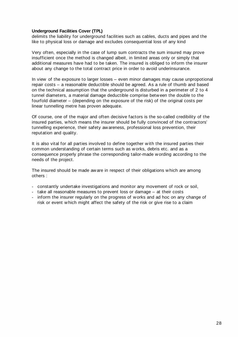
Underground Facilities Cover (TPL)delimits the liability for underground facilities such as cables, ducts and pipes and thelike to physical loss or damage and excludes consequential loss of any kind
Very often, especially in the case of lump sum contracts the sum insured may proveinsufficient once the method is changed albeit, in limited areas only or simply thatadditional measures have had to be taken. The insured is obliged to inform the insurerabout any change to the total contract price in order to avoid underinsurance.
In view of the exposure to larger losses – even minor damages may cause unpropotionalrepair costs – a reasonable deductible should be agreed. As a rule of thumb and basedon the technical assumption that the underground is disturbed in a perimeter of 2 to 4tunnel diameters, a material damage deductible comprise between the double to thefourfold diameter – (depending on the exposure of the risk) of the original costs perlinear tunnelling metre has proven adequate.
Of course, one of the major and often decisive factors is the so-called credibility of theinsured parties, which means the insurer should be fully convinced of the contractors’tunnelling experience, their safety awareness, professional loss prevention, theirreputation and quality.
It is also vital for all parties involved to define together with the insured parties theircommon understanding of certain terms such as works, debris etc. and as aconsequence properly phrase the corresponding tailor-made wording according to theneeds of the project.
The insured should be made aware in respect of their obligations which are amongothers :
- constantly undertake investigations and monitor any movement of rock or soil,- take all reasonable measures to prevent loss or damage – at their costs- inform the insurer regularly on the progress of works and ad hoc on any change of
risk or event which might affect the safety of the risk or give rise to a claim

29
8 Conclusions
Tunnelling projects in soft soil conditions are always on the borderline between safetyand economy. The less known about relevant geological factors, the greater thetendency to make assumptions and unfounded decisions, leading to even moreunpredictability. Often, not enough time and money are budgeted for in-depthinvestigations before and during the construction and instead of appropriating morecapital on additional studies, the risk may be transferred to the insurer.
Given the advances in tunnelling technology today, tunnels can be excavated invirtually all types of soil and environment, but there are still numerous unknownsparameters. During excavation, the situation can become critical at any minute, metre,and under any circumstance. If the entire tunnelling project is on a critical path, thereare no buffers or possibilities to reassign the SM and to shift the work force to otherareas if an incident halts excavation work.
The TPL exposure, even if not important in terms of MPL, must be carefully consideredin the assessment due to its high frequency.
Future tunnelling projects are certain to become even more demanding from thetechnical side and more complex with respect to management and control. Insurers areprepared to face the challenge, to consider new trends and methods and to providecover for such projects. They are prepared to assume material damage risks on thebasis of satisfactory and sufficient information and cover potential losses throughtailor-made wordings for the risk exposure as well as professional and fair lossadjustments.
However, this is possible in the long run, only if sound underwriting principles areapplied, risk adequate terms and conditions are achieved and no concessions aremade, regardless of market cycles.

30
9 Annexes
9.1 Pictures copyrights:Swiss ReMunich ReBabendererde Ingenieure GmbHHerrenknecht AG
9.2 Sample Endorsements:
Swiss Re
EPI 11 Underground Construction, Additional Costs Cover
________________________________________________________________________________
It is hereby agreed that as of the inception date of this Policy the following Condition isadded to the Special Conditions:
Notwithstanding anything contained to the contrary the insurance under Section 1Material Damage is in case of total or partial collapse of tunnels, shafts, caverns andsimilar underground works extended to indemnify the Insured in respect of additionalcosts of working arising in direct connection with repair or reconstruction as indemnifiedunder Section 1 incurred for
(a) replacement or restoration of rock or soil which supports or contributes to supportthe Property, if such rock or soil is lost or if its original state and structure has beendestroyed and/or
(b) difficult repair working conditions, alternative construction method, additionalequipment or work force, change of the works programme or
(c) localised deviation, subject to agreement by the Insurers which is to be obtainedprior to commencing any such deviation work.
Sum Insured in respect of each and every accident:
..................................................
Sum Insured in the aggregate for two or more accidents during the Period of Insurance:
..................................................
Swiss Re
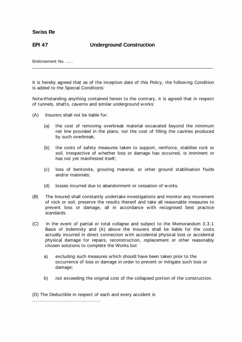
EPI 47 Underground Construction
Endorsement No. ....._________________________________________________________________________________________
It is hereby agreed that as of the inception date of this Policy, the following Conditionis added to the Special Conditions:
Notwithstanding anything contained herein to the contrary, it is agreed that in respectof tunnels, shafts, caverns and similar underground works:
(A) Insurers shall not be liable for:
(a) the cost of removing overbreak material excavated beyond the minimumnet line provided in the plans, nor the cost of filling the cavities producedby such overbreak;
(b) the costs of safety measures taken to support, reinforce, stabilise rock orsoil, irrespective of whether loss or damage has occurred, is imminent orhas not yet manifested itself;
(c) loss of bentonite, grouting material, or other ground stabilisation fluidsand/or materials;
(d) losses incurred due to abandonment or cessation of works.
(B) The Insured shall constantly undertake investigations and monitor any movementof rock or soil, preserve the results thereof and take all reasonable measures toprevent loss or damage, all in accordance with recognised best practicestandards.
(C) In the event of partial or total collapse and subject to the Memorandum 3.3.1Basis of Indemnity and (A) above the Insurers shall be liable for the costsactually incurred in direct connection with accidental physical loss or accidentalphysical damage for repairs, reconstruction, replacement or other reasonablychosen solutions to complete the Works but
a) excluding such measures which should have been taken prior to the occurrence of loss or damage in order to prevent or mitigate such loss or damage;
b) not exceeding the original cost of the collapsed portion of the construction.
(D) The Deductible in respect of each and every accident is..............................................

32
Munich Re
Endorsement 101
Special conditions concerning the construction of tunnels, galleries, temporary or permanentsubsurface structures or installations
It is agreed and understood that otherwise subject to the terms, exclusions, provisionsand conditions contained in the Policy or endorsed thereon, the Insurers shall notindemnify the Insured in respect of the expenses incurred for
• alterations in the construction method or due to unforeseen ground conditions orobstructions,
• measures which become necessary to improve or stabilise ground conditions or toseal against water ingress unless necessary to reinstate indemnifiable loss or damage,
• removing material which has been excavated, or due to overbreak in excess of thedesign profile and/or for refilling cavities resulting therefrom,
• dewatering unless necessary to reinstate indemnifiable loss or damage,• loss or damage due to breakdown of the dewatering system if such loss or damage
could have been avoided by use of standby facilities,• the abandonment or recovery of tunnel-boring machines,• the loss of bentonite, suspensions, or any media or substance used for excavation
support or as a ground-conditioning agent.
In the event of indemnifiable loss or damage the maximum amount payable under thisPolicy shall be limited to the expenses incurred to reinstate the insured property to astandard or condition technically equivalent to that which existed immediately before theoccurrence of loss or damage but not in excess of the percentage as stated below of theoriginal average per-metre construction cost of the immediate damaged area.
Maximum percentage payable: %