Embed Size (px)
Citation preview

-70MO 361 A DEMONSTRRTION OF A TRUSTED COMPUTER INTERFACE TnimE 1/2I A MULTILEVEL SECU..(U) NAVAL POSTGRADUATE SCHOOL
MONTEREY CA G E RECTOR MR87
mhhhhmmhmmhhlImommo os

LLL 2
- 3- ,- a ' w a aw .3w - ' .11 -W w

'- a
I]TiC FILE cPI
NAVAL POSTGRADUATE SCHOOLMonterey, California
SAUG 1 71987A. D
THESISA DEMONSTRATION OF A TRUSTED COMPUTER
INTERFACE BETWEENA MULTILEVEL SECURE COMMAND AND CONTROL
SYSTEM ANDUNTRUSTED TACTICAL DATA SYSTEMS
by
George E. Rector, Jr.
March 1987
Thesis Advisor Thomas J. Brown
Approved for public release; distribution is unlimited
7 ..
~87 8 i3 039

SECURITY CLASSIFICATION 0$ Tw,$ PAGE /.$ , j
REPORT DOCUMENTATION PAGEis REPORT SECURITY CLASSIFICATION lb RESTRICTIVE MARKINGS
UNCLASSIFIED _
2 SECURITY CLASSIFICATION AUTHORITY I OISTRIeUTIONIAVAILABILITY OF REPORT
lb DECLASSiCATIONIOOWNGRADiNG SCHEDUL Approved for public release;distribution is unlimited
a PERFORMING ORGANIZATION REPORT NUMBER(S) 5 MONITORING ORGANIZATION REPORT NUJVER(S)
ba NAME OF PERFORMING ORGANIZATION 60 OFFICE SYMBOL ?a NAME OF MONITORING ORGANIZATION(of applicable)
Naval Postgraduate Schoo Code 39 Naval Postgraduate School
fi ADDRESS C(,y. Satie. and ZIP Code) 7b ADDRESS (City,. St., and ZIPCode)
Monterey, California 93943-5000 Monterey, California 93943-5000
So NAME OF FUNDINGSPONSORING Sb OFICE SYMBOL 9 PROCUREMENT INSTRUMENT IOENTI?,CATION PjtM9ERORGANIZATION (It appliable)
Bc ADORE SS try. State. and ZI Code) 10 S0'JRCE OF %LNDING NkIMBERS
PROGRAM PROJECT TASK WOI -,TiELE6ENT NO INO ACCESS '4 NO
T.'LE Iiflclude Se't'Iy CIauS~fcaruon )i
A DEMONSTRATION OF A TRUSTED COMPUTER INTERFIC'9 BETWEEN A MULTILEVELSF.CURE COMMAND AND CONTROL SYSTEM AND UNTRUETED TACTICAL DATA SYSTEMS
RIERSONAc AUTmOR(S)George E. Rector, Jr.
'] 3 VP O'' RE aPORT ]b T* M( COVERED 114 DATE OF REPORT (Year. Aoonth Oay) J' PAC.E (0_%TMaster's Thesis ,O. To . 1987 March 161
'6 SFPLEFVENTARY NOTATION
COSATI CODES 1 SUBJECT TERMS (Confinue on ,'vente if necessary and d enlfty ty bieck nurnber)
PELD GROUP SUB.GROU P Computer Security, Multilevel Secure Computing,
Trusted Systems, Tactical Data Systems,9 BSTRACT (Continue on reverse of neceuary, and identify by block numbe )
The task of this research is to demonstrate a multilevel secureinterface between a system operating at multiple security levels andother untrusted systems operating at a single security level. Without atrusted interface device, these systems cannot be electronicallyconnected. All communications between the systems must be done manuallywith all information transfer being reviewed by a security officer.Only releasable information is printed or stored in a removable mediumand hand carried to the other system. In contrast, a trusted,mult'level secure guard can connect untrusted systems electronically andcontrol the release of sensitive information. This task willdemonstrate the ability of a multilevel trusted system 'to interface withuntrusted systems operating at different levels of security.
;0 D SR'3UTiON/AVAILABILITY Of ABSTRACT 21 ABSTRACT SECURITY CLASSIFICATION.NCLA$SIED,.jNLIMTD C SAME AS PT, Q3,OTIC USERS Unclassified
Ila NAMIE 0 RESPONSIBLE INDIVIDUAL |20 TELIPHONE (Include Area Code)|27'c OIIA S'MBOLThomas J. Brown (408) 646-2772 Code 62Bb
00 FORM 1473. e4 MAR 81 APR eatuon ay be used ulI e.t'autted SECURITY CLASSIFICATION OF T iS PAGEAll other editions are Obsolete
1

-- ---- -9CUORtY CLASUICAT14OR o t PAGSt (Shf. Doe Now**.
Item 18 Cont'dMarine Tactical Command and Control System (MTACCS)Marine Air Command and Control System (MACCS)InteroperabilitySecure GuardKernelReference MonitorGeminiCommand and Control (C2 )
DTIo
*COPY
INSPECTED
6
PAcc(.s1012 For
$,N 0o2-. L. 4--
SAUNITYR" CLAIP'CATI10 OP T0I PA5(VYen Does AWm 4
I-
.... . .. .. • .. ..... . . . .... . .. ., . : ,- , ,, .-. ., , .- . , -, ,.,.,: . ., -.. % ',.,;, . , ., ,..- .. , ,rn

Approved for public release; distribution is unlimited.
A Demonstration of A Trusted Computer Interface BetweenA Multilevel Secure Command and Control System and
Untrusted Tactical Data Systems
by
George E. Rector, Jr.Captain, United States Marine Corps
B.S., United States Naval Academy, 1976
Submitted in partial fulfillment of therequirements for the degree of
MASTER OF SCIENCE IN SYSTEMS TECHNOLOGY(Command, Control and Conmmunications)
from the
NAVAL POSTGRADUATE SCHOOLMarch 1987
Author. Geo~rge E. Rector44r.
Approved by: z u049Thomas J.Brown, Thesis Advisor
Mihe 0.Svrie- l~rrnn
Joint Commandhn oeontn;d Comm citaio~ns, aden- Group
3
ABSTRACT
'-The task of this research is to demonstrate a multilevel secure interface between a
system operating at multiple security levels and other untrusted systems operating at a
single security level. Without a trusted interface device, these systems cannot be
electronically connected. All communications between the systems must be done
manually with all information transfer being reviewed by a security officer. Only
releasable information is printed or stored in a removable medium and hand carried to
the other system. In contrast, a trusted, multilevel secure guard can connect untrusted
systems electronically and control the release of sensitive information. This task will
demonstrate the ability of a multilevel trusted system to interface with untrusted
systems operating at different levels of security.
4
r - :,, , ,,,. . ,., , .,,,,,,, .-. ,,,: .... ,,-..:;,;..,,,,,.,... . .... ,....: : . .,..,,....;./..,....,..-.; ,...:.:.

TABLE OF CONTENTS
INTRODUCTION ............................................. 10A. HISTORICAL PERSPECTIVE .............................. 10
B. MARINE CORPS TACTICAL DATA SYSTEMS (TDS) ........ 16
1. G eneral .............................................. 16
2. The Marine Tactical Command and Control (MTACC)system s .............................................. 16
3. Marine Air Command and Control System ................. 20
4. Other Tactical Data Systems ............................. 21
5. Interoperability ....................................... 21
6. Interface Requirements ................................. 22
7. System Security ....................................... 24
II. BACKGROUND .............................................. 27
A. MULTILEVEL SECURE COMPUTING SYSTEMS ............ 27
I. Trusted Computer System Requirements ................... 27
2. The Security Kernel and Guard Technology ................ 31
3. Data Encryption ...................................... 34
4. Sum m ary ............................................ 36
B. ?EM INI TRUSTED MULTIPLE MICROCOMPUTERBASE ............................................... 38
1. Description of Gemini System Components ................ 38
2. Gemini Resource Management Overview ................... 39
3. Gemini Secure Operating System (GEMSOS)A rchitecture .......................................... 40
4. Application Development Environment .................... 43
5. Sum m ary ............................................ 48
III. DEVELOPMENT OF A MULTILEVEL SECURE INTERFACE ...... 49
A . G EN ERA L .............................................. 49
1. O bjectives ............................................ 49
2. D esign C onstraints ..................................... 51
5

3. Summary of Design Decisions ........................... 51B. SYSTEM IMPLEMENTATION ............................. 53
1. Hardware Components ................................. 532. Application Program Format ............................ 53
C. SYSTEM SOFTWARE DESIGN ............................ 55
1. Application Segment Development ........................ 55
2. Process Synchronization ................................ 58
D. DESIGN SUMMARY ..................................... 58
IV. DISCUSSION OF RESULTS .................................... 61
A. SYSTEM OPERATION .................................... 61B. DEVELOPMENTAL PHASES .............................. 62
1. JINTACCS Automated Message Preparation SystemImplementation ....................................... 62
2. Intersegment Linkage of Multiple LanguageA pplications .......................................... 63
3. Communications ...................................... 654. Demonstration of GEMSOS Security Mechanisms ........... 67
C. SYSTEM TESTING ....................................... 67
D. OBSERVATIONS AND LESSONS LEARNED ................ 68
1. Applications Development with GEMSOS ................. 682. Development of Applications Using ADA .................. 693. Computer Security for Marine Tactical Data Systems ........ 70
4. Integrated Security Requirements ......................... 71
E. SUM M A RY ............................................. 73
V. CONCLUSIONS .............................................. 74
A. G EN ERA L .............................................. 74
B. RECOMMENDATIONS FOR FURTHER STUDY ............ 75I. Integration of JAMPS into GEMSOS ..................... 752. Implementation of a Polling Scheme ...................... 753. Modem Programming Techniques ........................ 76
APPENDIX A: GLOSSARY ........................................... 77
APPENDIX B: LIST OF ACRONYMS AND ABBREVIATIONS ............ 81
6
q d" " " € , • m • ' ..." •, •• °" " ". °.% • ." • %•" ""° % " -"". ' q" ° % °, " " ° ' % % °" "° J

APPENDIX C: INTERFACE USERS GUIDE ............................ 83
APPENDIX D: SYSTEM MANAGER PROGRAM LISTING .............. 86
APPENDIX E: GUARD.KMD LINKING FILE ......................... 121
APPENDIX F: GUARD-CON.ZLI INCLUDE FILE OF CONSTANTDECLARATIONS ..................................... 122
APPENDIX G: WtARD-TYP.ZLI TYPE DECLARATION INCLUDE .FILE..............................................123
APPENDIX H: TDSj TERMINAL UTILITY PROGRAM LISTING(JANUS ADA) ........................................ 124
APPENDIX I: DEFS.LIB LIBRARY DEFINITION FILE ................ 130
APPENDIX J: DEFS.PKG PACKAGE BODY FILE USED TOSUPPORT DEFS.LIB .................................. 132
APPENDIX K: TDS2 TERMINAL UTILITY PROGRAM LISTING ....... 139
APPENDIX L: TDS2.KMD LINKING FILE FOR TDS2.PAS ............. 155
APPENDIX M: GUARD.SSB SYSTEM GENERATION SUBMIT FILE ..... 156
LIST OF REFERENCES ............................................... 157
BIBLIOG RA PHY ..................................................... 159
INITIAL DISTRIBUTION LIST ........................................ 160
F
7%
~ .~ ~ . .. . . -s * *' 4.

LIST OF TABLES
I. TDS INTERFACE REQUIREMENTS AND INTERFACE LEVELS ....... 23
2. TDS COMMUNICATION INTERFACES ............................. 25
'8'Is
8r
2 ', ' :,." :'."".' : ''.., i :'k"':;'." ,',;,'.r..'..'2 .:'-.,'.2.'.r,.'.''2" '-'2'2 . .': . 2 . .;. 2"r '.,2'.> .'. X',',' ' ." ,"

LIST OF FIGURES
1.1 Marine Corps Tactical Data Systems ................................. 17
2.1 ECB Mode of DES Encryption ..................................... 36
2.2 CBC Mode of DES Encryption ..................................... 37
2.3 CFB Mode of DES Encryption ..................................... 38
2.4 Compromise and Integrity Properties ................................ 41
2.5 Single and Multilevel Device Properties ............................... 43
2.6 GEMSOS Hierarchical Structure .................................... 45
2.7 GEMSOS Hierarchical Structure Including an Application ............... 46
3.1 Proposed System Design ........................................... 52
3.2 Final Hardware Diagram .......................................... 54
3.3 System M anager Flow Chart ....................................... 57
3.4 Terminal Utility Flow Chart ........................................ 59
4.1 Revised Hardware Configuration .................................... 64
4.2 Computer System Vulnerabilities .................................... 72
9
.1~ ~ .dI

I. INTRODUCTION
As automation increases and our reliance on computer systems grows, it becomesincreasingly important to ensure that the information entrusted to these systems is
protected. Techniques to address information protection can be as simple as
procedural controls, or as complicated as controls embedded in the hardware and
software of the computer system itself Each technique addresses a particular
information protection problem and assumes that other techniques are available tosolve problems in other areas. This thesis addresses some of the problems involved
with computer security, specifically, computer security of tactical data systems. Thegoal of this thesis is to provide an introduction to the concept of computer security, to
focus on a particular area where computer security is vital--Marine tactical data
systems, and to demonstrate how a secure guard may be added to Marine tactical data
systems as a "first step" toward designing a multilevel secure computer system to
protect information vital to command and control of Marine forces.
Chapter I of this thesis provides an overview of computer security and introduces
Marine tactical data systems, their interoperability, and their interface requirements.
Chapter II provides a basic understanding of multilevel computing systems, specifically,the Gemini Trusted Multiple Microcomputer System. Chapter III describes the
development of a demonstration of the Gemini Trusted Computing Base (TCB) used as
a guard between Marine tactical data systems operating at multiple levels of security.
Chapter IV discusses the implementation of the demonstration, its testing and "lessonslearned". Finally Chapter V provides conclusions drawn from this research and
recommendations for further study.
A. HISTORICAL PERSPECTIVE
Computers are here to stay. They are permeating every facet of society from
games to managing information critical to our national security. Information has
become a strategic resource. The availability of computers has moved us from anindustrial society to an information society. Our C31 posture is critically affected by
and dependent on computers. Their speed and unfailing accuracy make them well
suited to the massive information handling tasks in battle management for:" Shared information storage. retrieval and dissemination
* Rapid and common processing systems
10

* Efficient and reliable communications process control [Ref. 1: p.271].
Relying on computers to carry out timely and reliable information transfer raisesthe question, can they be trusted? Trust and reliability in computer software and
hardware are not necessarily synonymous. First, what vulnerabilities must we guard
against and next, what is needed to bridge the gap between the plain vanilla computer
and the trusted computer?
Rapid advances of hardware and software technologies in microelectronics,
computers, network systems and man-machine interfaces are making major changes intoday's C31 architecture approaches. Modem C3 I systems will be implemented by new
architectures consisting of a large number of networks, computers, processors and
input,'output devices. However, many of the computer and network systems used to
support modem C31 technologies must handle sensitive information and work in acompletely secure environment. Information used with today's C3I systems must be
protected.To better understand the role of computers in information protection, let us look
at how our evolving use of computers has brought with it computer security problems.
This will help determine what can and cannot be done to protect our newest strategic
resource.Until the mid-1950's, computers were commonly dedicated to one user at a time
and security was of minor concern. The user either worked on his own behalf or as a
programmer for someone else. The computer power was limited. With reasonable
planning, the user kept the machine busy for his period of use. The jobs were typically
processing of numerical data which required only a limited amount of software and
data. The user brought with him all the data (card deck) and no one else could affect
the machine while he used it. If he had sensitive data, he could easily purge the small
bit of information in the machine and take all of his data and results with him when hefinished. Thus, with no sharing of the machine and no sharing of data, the user was in
control of his own security. [Ref. 21
Later, in the 1960's more powerful and much more expensive computers could
not be dedicated to just one user. The human was just too slow to efficiently employthe machine and usage expanded. Software packages called operating systems or
monitors evolved and computers were shared by multiple users. In this mode, the
machine was under the physical control of a computer operator, not the user. Mostcommon and useful operating systems employ multiprogramming or timesharing so that
1
several jobs may run simultaneously. Regardless of the operating system particulars,
the computer is in control of its resources, not the user. In this environment, the
nature of computer security becomes quite clear. The operating system software is
more privileged in some sense than the user. This poses no problem as long as the
operating system is trusted. It did not take long to discover that a malicious user could
easily penetrate the operating system and cause it to share its privileges. [Ref. 21
An answer to this problem of non-existent internal security is to eliminate any
user who is not authorized access to the information. This method of security can be
effective, but it has two disadvantages. It can be quite expensive, since it limits sharing
of the computer's resources to a common need to know. It can also encourage
imprudent risks because of the temptation to increase sharing by treating all users as
honest when they may have no need to know or may even be hostile. The distinctive
characteristic of a shared system is that security can be provided by isolating the users
into compatible groups that share machine resources.
Since the mid-1960's, computers have been increasingly used for this purpose in
information management. The principle capability of these systems is access control
vice processing. These controls can be as simple as distinguishing whether a user can
read only or both read and write a file to more complex controls over access--such as
those implicit in the military classification levels.
For example, wargaming centers often have a need to provide war games at
several levels of classification using a single software system and a large classified data
base. Frequently the users, who are expected to participate through hands-on use of
the computer, have no clearance or clearance at a level lower than might be required.
This forces downloading of the sensitive portions of the data base, a disruptive practice
in a wargaming center. The use of a trusted guard could control the access to the data
base and allow operation of games with various levels of classification using a single,
fixed classified data base.
Information systems and networks are rapidly expanding in the private sector as
well as the military. The available isolation techniques are not workable--since the
need is to provide controlled (shared) access via the computer. This means that we
have no alternative but to develop internal controls for the computer itself--new, more
powerful, and trusted operating systems.
From this perspective, we can see that there are basically two kinds of responses;
limit the opportunity to do harm and, in doing so, we reduce the vulnerabilities- and
stimulate industry to apply emerging technology to counter these vulnerabilities.
12
A fundamental step in shoring up the technical weakness of today's computers isdefining a clear, well formulated policy to influence secure computer system designs.
The computer designer must be told exactly what policy the system must enforce. Thecomputer cannot make a judgment regarding the user's request for access to stored
information. It can only grant or deny access based on the authority that it has beengiven. Thus, what is needed, as a basis for any trusted system, is a policy thatarticulates well defined authorizations to information and computer resources.
There are many documents which attempt to define requirements for trustedcomputer systems. They have been generated at all levels of the government, and in
some cases are in conflict with each other. In 1983 an attempt was made within the
Department of Defense (DOD) to consolidate these documents as well as otherinformation concerning trusted computer systems. The goal was to create a singlesource document which would define guidelines for the development and testing of new
systems. The result was entitled "DOD Trusted Computer System EvaluationCriteria," commonly referred to as the 'Orange Book' [Ref. 3]. Published in 1983, itcontains definitions and information essential to understanding trusted computersystems. The Orange Book goes into extensive detail concerning the implementation of
automated data processing (ADP) security systems. As described in the Orange Bookthere is mandatory security which is defined as:
Security policies defined for svstems that are used to process classified or otherspecifidallv categorized sensitive information must include provisions for theentorcement of ffiandatorv access control rules. That is. they must include a setof rules for controlling a6cess based directly on a comparisoh of the individual'sclearance or authorization for the information and the classification or sensitivitvdesignation of the information being.sought, and indirectly on considerations ofphysical and other environmental Tactos of control. The mandatory accesscoitrol rules must accurately reflect the laws, regulations, and generar policiesfrom which they are derived. '[Ref 3: p.72]
As the name implies, mandatory security policy is a strict limitation of accessbased o,1 access level, which is determined by the user's security clearance. This policycan not be changed and represents the foundation for the second type of security
policy. Discretionar' security policy is a subset of mandatory security policy whichrepresents a further restriction of access to information based on a user's "need to
know" the information. The control objective for discretionary security is:
Security policies that are defined for systems that are used to process classifiedor other sensitive information must iiclude provisions tbr the enforcement of'
13
iI
... A

discretionary access rules. That is, they must include a consistent set of rules forcontrolling and limiting access based on identified individuals who have beendeterminea to have a need-to-know for the information. [Ref. 3: p.73]
This type of security is a definite asset in a research and developmentenvironment. For example, when developing combat system software, a projectmanager may have teams developing several modules simultaneously on the same
system. Although the modules may be of the same classification level, the managermay want to limit each team's access to the module on which they are working. Thiswould be accomplished by establishing a discretionary security policy.
Traditional attacks on security systems have involved compromise of keywordswhich would allow unauthorized access to a system. This threat can largely be
eliminated by physical means: changing keywords, multi-level identification, and
restricting access to the system. A more subtle attack, and potentially more dangerousthreat is the establishment of a covert channel in the system. A covert channel isdefined as "any communications channel that can be exploited by a process to transfer
information in a manner that violates the system security policy." [Ref. 3: p.79] In amulti-level computer system, the presence of a covert channel can be exploited to gainunauthorized access to information without alerting security mechanisms. Covert
channels will be discussed further as a design consideration for a multi-level secure
communications system.
One of the most difficult tasks in developing trusted computer systems isdetermining test criteria to evaluate their performance. As the security level is
increased, the test criteria become more stringent and detailed. When operating in a
network environment, the problem is compounded by requiring communications
security between the trusted computer systems as well.
Although such an explicit policy is necessary, it is not sufficient; the problem
remains the effectiveness of the operating system. One technology that can provide
penetration-proof controls is a security kernel. A security kernel is essentially a small
subset of an operating system and its associated hardware that will guarantee internal
enforcement of an explicit security policy, independent of the rest of the operating
system or user programs.
The security kernel is a breakthrough that has transformed the designer's game of
wits with penetrators into a methodical design process. Since early kernels were first
introduced in 1972, further research has demonstrated their feasibility, functionalitV
14

and broad certifiability. With such technology available, vendors are now beginning to
offer kernel based operating systems. Its successful implementation will enable
computers to thwart subversion attacks aimed at unauthorized access, disclosure,
modification or disruption of service of a computer-based C31 system. This entails not
only converting policy objectives into technical standards based on a mathematically
sound means to specify security requirements, but also the means to verify their design
and implementation and to maintain continuous control upon acceptance.
Computer development in the past decade has made considerable progress in
meeting multiple level security requirements. There have been several approaches to
these requirements. Security kernel technology has been more successful and is the
main basis for practical computer security products. For example, under Navy
sponsorship, Honeywell has developed the SCOMP (Secure Communications
Processor) using a security kernel. Under Air Force sponsorship, IBM/ITT is about to
deliver the SACDIN (Strategic Air Command Digital Network) processor which also
uses a security kernel. Both the SCOMP and SACDIN secure processors use a single
minicomputer.With increasing recognition of the security problems in both computer and
network systems and recent security policy developments in the Department of Defense
(DOD), it would be useful for a research effort to start at the Naval Postgraduate
School for the support of DOD wide security requirements in C31 developments.
A new distributed C31 testbed is being developed using the Gemini trusted
multiple microcomputer base to support some of the C31 related research topics at the
Naval Postgraduate School. There are three ways to address the security problems
that form the. foundation for this research.
* For untrusted computers and!or networks which already have been developedand are in operation today, such as the MILNET, new inultilevel secure guarddevices are potential candidates.
• For networks which are still being developed such as DDN, new trustedinterface units could be developed to support multilevel security requirements.
• For new systems which have not been designed, new trusted computer systemtechnotoei~s can be included in the svstemf design to sup-port new multilevelsecure CI systems satisfying the DOD'ComputerSecunty Center s criteria.
This thesis investigates the use of a trusted computing base (TCB) to act as a
multilevel secure interface between the tactical data systems (TDS) of the Marine
Corps. This thesis proposes that the Marine Corps Tactical Intelligenge Management
System (TIMS) act as a multilevel, trusted, systems manager with the ability to
15
% A

communicate with untrusted systems operating at single levels of security such as the
Tactical Combat Operations (TCO) System, the Advanced Tactical Air Control Central(ATACC), the Marine Integrated Fire and Air Support System (MIFASS), and the
Tactical Air Operations Module (TAOM). Therefore, TIMS would act as the primaryinterface and the center of information for the Marine Corps tactical data systems.
B. MARINE CORPS TACTICAL DATA SYSTEMS (TDS)
I. GeneralThe automated systems discussed in this section are those currently existing or
projected to support the exchange of tactical information for the Marine Corps. Eachwill be described below. More detailed descriptions may be found in current Marine
Corps documentation such as the U. S. Marine Command and Control Master Plan
(C2 Mp) [Ref. 4] and systems requirements documents and specifications. The MarineCorps tactical data systems are a conceptual association of command and control
systems to support tactical operations. It consists of functionally oriented, tactical and
training systems, using, where feasible, common equipment, operational procedures,data bases, and design philosophy. These systems, where appropriate, will interoperate
through a common communication system as depicted in Figure 1. 1
2. The Marine Tactical Command and Control (MTACC) SystemsIn order to receive, process, store, display and forward the large quantities of
information that will be available on the modem battlefield in a useful and timely
manner, selective application of automation within operations centers is required tosupport the command and control of Marine Air-Ground Task Forces (MAGTF). A
semi-automated, hardened, secure, and transportable command and control system,capable of interfacing with existing Marine communications systems, is required in
operations centers to provide real-time data input/output, storage, display, retrieval
and processing support to the commander in the performance of his operations,planning, and intelligence functions. The Marine Tactical Command and Control
System (MTACCS) is a conceptual association of command and control systems to
support tactical operations. It consists of six functionally oriented tactical and trainingsystems, using, where feasible, common equipment, operational procedures, data bases,
and design philosophy, and, where appropriate, interoperating through a common
communications system.
The six systems included in the MTACCS concept are:Marine Integrated Fire and Air Support System (MIFASS)
16
* *. 5'-'l

I- IU r4
2
U 6 04 4~ U,
U -
0' £Ua -
C,,
4U 2 -
*1U .4U U.
C-,
A' o
0
.4.
C-
.5
17

* Tactical Combat Operations (TCO) System0 Tactical Air Operations Module (TAOM)
* Marine Air-Ground Intelligence System (MAGIS)* Position Location Reporting System (PLRS)" Tactical Warfare Simulation Evaluation and Analysis System (TWSEAS)
The following paragraphs from the C2MP provide an overview of how each
MTACC system contributes to the whole configuration. This will be accomplished by
presenting a summary description of their design objectives and by describing
functional boundaries or limits for these systems. '
a. Marine Integrated Fire and Air Support System (MIFASS)
MIFASS performs the critical function of coordination and control of
supporting arms. This is accomplished by integrating, directing, and coordinating
artillery, mortar, naval gunfire, and air support. Real-time friendly position location
reporting such as that provided by PLRS and the TAOC is essential to the effective
operation of MIFASS so that its rapid response capabilities can be fully realized.
MIFASS consists of suites of modular microprocessing and display equipment and
software tailored to the functions performed at a given level of command. It is
characterized by the commonality of equipment with other MTACC systems, especially
TCO with which it may share much of its equipment at some echelons.
b. Tactical Combat Operations (TCO) System
As the title implies, TCO is the system which will provide the commander
his principal assistance in combat operations planning, monitoring, and coordinating.
TCO will provide commanders with the capability to accomplish the planning and
direction of combat operations. Modular microprocessing and display equipment.
tailored for the using command, will be provided to MAGTF commanders at all levels
from the Marine Amphibious Force (MAF) down to battalion and squadron. Digital
Communications Terminals (DCTs), capable of transmitting and receiving combat-
essential information to and from battalion and squadron level, will be provided below
these levels. This will permit, in addition to other functions. the transmission of
forward-echelon combat information via TCO channels for entry into the Marine Air-
Ground Intelligence System (MAGIS). TCO is expected to become one of the
principal means by which information is passed to MAGIS. Conversely, intelligence
and information produced by MAGIS will be provided to echelons below MAF via
TCO. Friendly position location information (PLI), such as that available from the
18
Tiq,,-,W. ,,¢,r ~ 'o 'o , -;i., ,- i- ,,-ii .. -. .' • • - " -. ' ". .- '. ." " " . ".'."- - . -. -. ".' ,' '' '. ". . ."".

Position Location Reporting System (PLRS), is essential for TCO system operations.
TCO will be used to support staff operations and intelligence functions at all echelons "
of command. By receiving, via the Landing Force Integrated Communications System
(LFICS) and Joint Tactical Information Distribution System (JTIDS), and displaying
selected data from MIFASS, MAGIS, PLRS, and TAOM, TCO will provide the focal
point at which the commander can obtain his operational information and disseminate
command decisions.
The TCO mission is to provide an accurate data input, storage, information
retrieval, and processing system for the real-time support of ground, aviation and
MAGTF operational functions and those intelligence functions below MAF level (not
supported by MAGIS/IAC) within operations centers.
c. Tactical Air Operations Modue (TAOM)The TAOM will provide the Tactical Air Commander (TAC) with the
means to monitor, coordinate, and control intercept aircraft and surface-to-air missile
systems, including Forward Area Air Defense (FAAD) weapons, and to give enroute
traffic control assistance to aircraft within the MAGTF area of responsibility. It is a
modular system which can be tailored to meet the requirements of any size MAGTF "-
from a Marine Amphibious Force (MAF) to a Marine Amphibious Unit (MAU). In
order to augment its organic radar coverage capabilities for effective execution of the
TAOM air defense mission, the TAOM system exchanges TADIL-B position location
information with the senior MIFASS-supported FASC.d. Marine Air-Ground Intelligence System (MA GIS) %
The primary function of MAGIS is the processing of information
concerning the enemy, weather, and terrain into timely, accurate, detailed, all-source
intelligence in support of the tactical commander. The AN/TYQ-19(V) IAC, is a
tactical intelligence processing facility which will serve as the heart of MAGIS. The
IAC will accept information from the Imagery Interpretation segment, Tactical
Electronic Reconnaissance Processing and Evaluation System, Integrated Signals
Intelligence System, MAF Reconnaissance and Surveillance Center, division and wing
intelligence centers, TCO, and other sources for processing into intelligence. Normally,
one IAC is assigned to each MAF and may be retained at the MAF headquarters or
assigned to the Air Combat Element (ACE), or the Ground Combat Element (GCE)
Headquarters. The automated intelligence functions will be supported by the Tactical
Intelligence Management System (TIMS). TIMS will handle intelligence information %
19
.1
".wa'aV%' - % .," ." " ', 1,, . . ."-" " ' . -.". . . . . . *,= ." - .~% -% -. =%%"% %-, .% -- * . , -** °. ...- . .- '.'

with a classification above secret and TCO will handle intelligence information with a
classification of secret or lower.
e. Position Location Repotring System (PLRS)
PLRS performs the function of position location reporting of PLRS-
equipped units, vehicles, and aircraft essential to TCO and MIFASS maneuver andfirepower coordination and control. Its capability of locating friendly units, vehicles,
and aircraft brings the element of real-time, accurate, current PLI to the battlefield
commander.
f. Tactical Warfare Simulation, Evaluation, and Analysis System (TWSEAS)
Tactical Warfare Simulation, Evaluation, and Analysis System. TWSEAS is
a tactical command and control system, with multiple capabilities for supporting
virtually all types of tactical exercises conducted in the Marine Corps. TWSEAS is not
a combat system; its role is training support. TWSEAS is a mobile facility designed
and configured for sustained operations in the field with tactical units during training
exercises. TWSEAS can function as a control center for an exercise, or be used to
support staff exercises, such as map maneuvers, which are not necessarily conducted in
the field.
3. Marine Air Command and Control System
MACCS comprises those agencies that support the air commander in the
exercise of centralized coordination and supervision of air operations while
decentralizing control to subordinate agencies. The systems supporting MACCSagencies are described in more detail below. Their general concept of employment is
discussed in the C2 Mp.
a. Tactical Air Operations tlodule (TA OAl)
TAOM is a transportable, modular, software intensive, automated element
of the aviation C2 system. It provides the primary link between MTACCS andMACCS. It is therefore listed as a subsystem for both. The TAOM is capable of
controlling and coordinating the employment of air defense weapons in support of any
size MAGTF.
h. Advanced Tactical Air Command Central (A TA CC)
ATACC is a computer-supported facility which provides the TAC with theresources needed for planning and directing the air battle. It is the senior Marine air
command and control agency from which the TAC exercises overall supervision.coordination and general control of tactical air operations. Subordinate agencies from
20

which the TAC exercises these functions include the TAOC, DASC, Marine air traffic
control squadrons, and terminal control action elements.
c. Marine Air Traffic Control and Landing System (MA TCALS)
MATCALS provides semi-automated and automated capabilities for
aircraft surveillance, identification, tracking, vectoring, track hand-over, and cross-
telling. This system provides automated tracking based on correlation of radar;
identification, friend or foe; and data-link replies. The system provides simultaneous
landing control. It may control up to six aircraft with a routinely sustained landing
rate of one aircraft per minute, and has the technical capability of increasing the rate
to two aircraft per minute.
d. Other MACC SystemsOther systems to be included in the Marine Air Command and Control
System include the Marine Remote Area Approach and Landing System (MRAALS ,
Tactical Data Communications Central (ANi'YQ-3), Direct Air Support Central
(DASC), Hawk Missile System, and a host of radar sets.
4. Other Tactical Data Systems
Other tactical data systems include:
* Battery Computer System (BCS), AN'GYK-29.
* Radar Set, Firefmder, AN/TPQ-36.
* Field Artillery Meterological Data System (FAMDS), AN/TMQ-31.* Modular Universal Laser Equipment (MULE), AN,PAW-3.
Additional detail on each of the tactical data systems listed may be found in the C2 Mp
[Ref. 4] and other reference materials associated with individual programs.
5. Interoperability
Exchange of information between agencies participating in a tactical
(amphibious) operation is critical to the success of the overall mission. Equipment in
operations centers will provide the facilities required to achieve necessary
interoperability of information exchange with tactical data systems and the systems of
other services to support commanders at all echelons. Data exchange standards will be
in accord with the provisions of the U. S. Marine Corps Technical Intert'ce Design
Plan (TIDP) and Technical Interface Concept (TIC) [Ref. 5: p. 1-51. The interface
standards for data exchange between Marine tactical data systems and other service
systems will be in accord with the provisions established by the Joint Interoperability
of Tactical Command and Control Systems (JINTACCS) plan.
21v
6. Interface Requirements
In describing interoperability between systems, the levels of interface are
categorized into three levels: manual, semi-automated, and automated. In Table 1
from [Ref. 6: p. 4-41, the level of interface is defined for both sides of each interface.Where the same level of interface exists at the systems on both sides of the interface, a
single designator appears in the matrix at the intersection of the column and row for
the two systems. For example, at the intersection of the row opposite "TAOM" andthe column headed "ATACC', the letter "S" appears, indicating that each system has a
semi-automated interface with the other system. Where the levels of interface are notthe same on both sides of the interface, the letter in the upper side of the box at the
intersection indicates the level of interface of the system at the head of the column.
The level of interface for the system named on the left side of the row is indicated by
the letter in the lower half of the box.Table 2 from the Technical Interface Concept for Marine Tactical Systems,
[Ref. 6: p. 4-6], depicts the general character of the interface. The communication
medium, requirements for controllers, and the use of TADILs are portrayed. The
actual physical interface in each case is provided by either or both of the following
means:
" Cable; e.g., fiber optic cable, 26-pair cable, and wire." Radio; e.g., single channel and multichannel.
An additional element of an interface may be an interface device or interface
controller. Such a device is necessary where the interoperating systems useincompatible circuit and/or message standards or operate at different levels of security.
Examples of interfaces requiring interface devices are:" MIFASS -PLRS
• MIFASS -TACFIRE
" TCO - MAGIS'ITAC
• TCO -ATACC
* TCO- PLRS
* TCO-MIFASS
Tactical Data Interface Links (TADIL) are used to achieve interoperabilitybetween Marine Corps TDSs and other service systems, and among some Marine
Corps systems. A TADIL is a JCS-approved. standardized, communications link
suitable for transmission of' digital data. TADILs are characterized by standard

TABLE 1
TDS INTERFACE REQUIREMENTS AND INTERFACE LEVELS
U. C ?
PLRS A A
MIFASS A A AS A M AS S
To A AS ILS M
DOT is sM MI I Sl S
AN/TYfQ-1 SM M IM IIATACC SS S Sl Is Is S
AN/TYQ-2 SsM MIMMA A I
TAOM Al S S M MM SAA I
AN/'TSO-122 M M IM MIIDASC MMIMI MIM IMI II I
RGDBS M MIMMI
MATCALS M Si M MHAWK 6CC A
HAWK AFU A
BOS Al S I SS S
FAMOS sI IS
AN/TPO-36 ISl ISMULE-----------------I
IAC I S IS S S SIM S
TERPES IIS I
IF ISl IMI
ASIP IS M
TIMS M M MM MM
TCAC S MISA
CCO A S
AIRCRAFT M M SIAM MAA A
AN/TPS-32AI
AN/TPS-39 A
ANITPS -63 Al
M:- Manual S: Semi-automaic A. AuJtomatic
23

message formats and transmission characteristics. TADILs appearing in table 2 are
listed below-* TADIL A (NATO Link 11)." TADIL B." TADIL C (NATO Link 4A).
* TADIL J (NATO Link 16).
* ATDL I.
* NATO Link 1.
7. System Security
The protection of tactical data systems is vital to landing force safety and
imposes stringent requirements for system security. The primary elements which
implement this protection are TDS equipment and program features, physical security
measures, procedural features, and access controls. These features provide the in-
depth, mutually supporting protection of classified material as well as system integrity.
24
W 4 % ~ J3
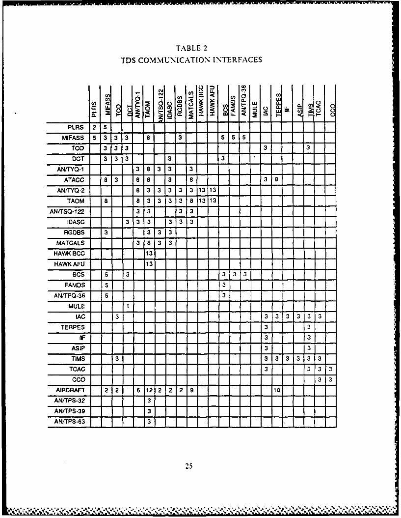
TABLE 2
TDS COMMUNICATION INTERFACES
(n 4 a a.
PLRS 2 5
MIFASS 5 3 3 3 8 3 5 5 5
TCO 3 3 3 3 3
DCT 3 3 3 3 3 1AN/"YQ-1 3 8 3 3 3
ATACC 8 3 8 8 3 8 3 8
AN/TYQ-2 8 3 3 3 3 3 13 13
TAOM 8 8 3 3 3 3 8 1313
AN/TSQ-122 3 3 3 3
IDASC 3 3 3 3 3 3 1
RGDBS 3 3 3 3
MATCALS 3 8 3 3
HAWKBCC 13
HAWK AFU 13
BCS 5 3 3 3 3
FAMDS 5 3
AN/TPQ-36 5 3
MULE 1
IAC 3 3 3 3 3 3 3
TERPES 3 3
IF 3 3
ASIP 3 3
TIMS 3 3 3 3 3 3 3
TCAG 3 3 3 3
CCO 3 3
AIRCRAFT 2 2 6 12 2 2 2 9 10
AN/TPS-32 3
AN/TPS-39 3
AN/TPS-63 3
25

TABLE 2
TDS COMMUNICATION INTERFACES (CONT'D.)
LEGEND1
1. Cable; e.g., fiber optic cable, 26-pair cable and wire
2. Radio, e.g., single channel and multichannel
3. Cable and radio
4. Cable with an interface controller
5. Cable and radio with interface controller
6. Radio with TADIL A
7. Radio with TADIL B
8. Cable and radio with TADIL B
9. Radio with TADIL C
10. Radio with TADIL B
11. Radio with TADILs A and J
12. Radio with TADILs C and J
13. Cable and radio with ATDL 1
14. Cable and radio with NATO Link 1
2 6
S

II. BACKGROUND
A, MULTILEVEL SECURE COMPUTING SYSTEMS1. Trusted Computer System Requirements
As computer systems have become more sophisticated and widespread in their
applications, the need to protect their integrity has grown. Protection is often thought
of as a supplement to multiprogramming operating systems, so that untrustworthyusers might share a common logical space, such as a directory, or a common physical
space such as memory. Modem security concepts have evolved to increase the
reliability of any complex system which makes use of shared resources.
In general, secure systems will control, through the use of specific security
features, access to information [Ref. 3: p. 31. Protection refers to the mechanism forcontrolling the access of programs, processes, or users to the resources defined by a
computer system. This mechanism must provide a means for specification of the
controls to be imposed, together with some means of enforcement. There are severalincentives for protection. Most obvious is the need to prevent mischievous, intentional
violation of an access restriction by a system user. Of equal importance is the need to
ensure that each program component active in a system uses the system resources only
in ways consistent with stated policies. This is an absolute requirement for a trusted
system.
A computer system may be viewed as a collection of processes and resources.
To ensure the orderly and efficient operation of a system, the processes are subjected
to policies that govern the use of resources. The role of protection in a computer
system is to provide a mechanism for the enforcement of the policies governing
resource use. These policies may be established in a number of ways. Some are fixed
in the design of a system, while others are formulated by the management of a system.
A protection system must have the flexibility to enforce a variety of policies that can
be declared to it.
Policies for resource use may vary, depending on their application, and they
may be subject to change over time. For these reasons, computer security can not beconsidered solely as a matter of concern to operating system designers. It should beavailable as a tool for the applications programmer, so that resources creatcd and
.4.
27
£ ~ ~ C ~" or % % * ***~ .... ..-...-..

supported by an application may be guarded against misuse. There must be protection
mechanisms provided so that applications designers may use them in designing their
own protection software.
One important principle is the separation of policy from mechanism.
Mechanisms determine how to do something while policies determine what will be
done. This separation is very important for flexibility. Policies are likely to change
from time to time or place to place, whereas, mechanisms should be more general, only
requiring modification of certain parameters or minor change.
A computer system is a collection of processes (or subjects) and objects.
Objects may be hardware objects (such as the cpu, memory segments, printers, card
readers, or tape drives), and software objects (such as files, programs, and semaphores).
Each object has a unique label that differentiates it from all other objects in the systemand can be accessed only through well-defuied and meaningful operations.
Obviously, a process should be allowed to access only those resources it has
been authorized to access. Furthermore, at any time it should be able to access only
those resources that it currently needs to complete its assigned task. This requirementis commonly referred to as the need-to-know principle or discretionary access control.
This principle is useful in limiting the damage that a faulty process can cause a system.
These access controls shall be capable of specifying, for each named object, a listof named individuals and a list of groups of named individuals with theirrespective modes of access to that object. Furthermore, for each such namedobject, it shall be possible to specify a list of named individuals and a list ofgroups of named individuals for which no access to the object is to be given.[Ref. 3: p. ,43]
This introduces the concept of a protection domain. A process operates
within a protection domain, which specifies the resources that the process may access.
Each domain defines a set of objects and the types of operations that may be invokedon each object. The ability to execute an operation on an object is an access right. A
domain is a collection of access rights, each of which is an ordered pair < object-name.
rights-set>. For example, if domain A has the access right < file X, read,write>, then
a process executing in domain A can both read and write file X, it cannot perform any
other operation on that object.A domain is an abstract concept which may be realized in a number of ways:
* A domain mav be defined for each user. The set of objects which can beaccessed depenls on the identity of" the user.
28
- x.e "Q', _.Z.'- '.." .... - . ....... • -.. _......'-_ '..'....._A. . .' ' '.'m . " . ,

"=URN" Pon~ % 1
* A process may be a domain. Each object which can be accessed by thatprocess is descfibed. Also each operation which may be performed is defified.
* Each procedure may be a domain. Thus, each object which may be accessed bythat procedure is d6imed.
The degree of protection provided in existing computer systems has usually
been achieved through a security kernel, a guard which inspects and validates each
attempt to access a protected resource. Since extensive access validation is potentially
a source of considerable overhead, it must either be given hardware support to reducecost, or one must accept that the system may be designed with lower goals of
protection. It is difficult to satisfy all of the goals if the flexibility to implementvarious security policies is restricted by the support mechanisms provided.
As operating systems have become more complex, and particularly as they
have attempted to provide higher-level user interfaces, the goals of protection have
become much more refined. In this refinement, we find that designers have drawn
heavily on ideas that originated in programming languages, especially on concepts such
as abstraction, layering, virtualization, and information hiding. Protection systems are
now concerned not only with the identity of a resource to which access is attempted,
but also with the functional nature of the access.
Policies for resource use may also vary, depending on the application. For
these reasons, protection can not be considered solely as a matter of concern to system
designers, it must also be available as a tool for the applications designer in order that
applications may be guarded against tampering or the influence of an error.
There are two documents which provide the basis for evaluation of the
effectiveness of security controls built into computer systems or networks. These
documents are distributed by the National Computer Security Center located at Fort
Meade, Maryland. They are the Department of Defense Trusted Computer System
Evaluation Criteria (CSC-STD-001-83) dated 15 August 1983 and the Department ofDefense Trusted Network Evaluation Criteria (draft) dated 29 July 1985. These two
documents form the foundation for all acceptable secure computer systems.
To call any computer system "secure," a set of requirements must be
established. There are six fundamental requirements presented in [Ref 3] as the
absolute essentials for obtaining a secure system. Four of these requirements deal withthe means to be provided to control access and two deal with how one can obtain
credible assurances that this is accomplished in a trusted computer system.* Requirement one -- SECURITY POLICY -- There must be an explicit and well
detined security policy enforced by the system. Given identitied subjects and
29
V1$ %% .~.4.U ~ *4~.* % %. A~ - * . . 4 . . - - -- -- *4 ~ ~.4

objects, there must be a set of rules that are used by the systemy to determinewhether a given subject can be permitted to gain access to a specified object.
SRequirement two -- MARKING -- Access control labels must be associatedwith objects. In order to control access to information stored in a computer,according to rules of a mandatory security policy, it must be possible to markevery object with a label that riliablv identifieg the object's sensitivity levei,and,or modes of access accorded thosi subjects who may potentially acdess theobject.
• Requirement three -- IDENTIFICATION -- Individual subjects must beidentified. Each access to information must be mediated based on who isaccessing the information and what classes of information they are authorizedto deal with.
• Requirement four -- ACCOUNTABILITY -- Audit information must beselectively k.ept and protected so that actions affecting security can be traced tothe responsible party. A trusted system must be able to record the occurrencesof security-relevant events m an addit log.
* Requirement five -- ASSURANCE -- The computer system must containhardware, software that can be independently evaluated to _provide suflicientassurance that the system enforces requiremeits one through 'our above.
* Requirement six -- CONTINUOUS PROTECTION -- The trusted mechanismsthat enforce these basic requirements must be continuously protected againsttampering and or unauthorized change. No computer systemh can be consideredtrulv secure if the basic hardware and software mechanisms that enforce thesecdiritv policy are themselves subject to unauthorized modification orsubveriion. [Kef. 3: pp. 3-4]
Derived from these six basic requirements are the criteria for evaluation oftrusted computing systems. The criteria are divided into four divisions, D: minimal
protection, C: discretionary protection, B: mandatory protection, and A: verifiedprotection, ordered in a hierarchical manner from lowest to highest. Each division
represents a major improvement in the overall confidence one can place in the systemfor the protection of sensitive information. A rating for a system is based on thoroughtesting of the security relevant portions of the system. The security relevant portion of'
the system is spoken of as the Trusted Computing Base (TCB).Division D: Minimal protection has only one class and is reserved for systems
that have been evaluated, but failed to achieve the standards of a higher class.Division C: Discretionary protection contains two classes that provide
discretionary access to information and the means to audit and account for such usage.The two classes are: class Cl: discretionary security protection and class C2: controlledaccess protection. The Trusted Computing Base (TCB) of cla s Cl satisfiesdiscretionary access requirements by separating users and data. The class C Ienvironment is expected to be one of cooperating users processing data at the same
level of sensitivity [Ref. 3: p. 12]. Identification and authentication are required todetermine authorized individual or group users. The discretionary control of' class (2
30
W 100 "e p" , , ¢ " €, 'j , 'I* ,, ,.. ' ....' ', .'. Vf.. P"." '. -%'.'.. .-' .. " -. .... .. .

is made more rigid through login procedures, auditing of security relevant events, and
resource isolation. By limiting usage to specified individuals, accountability for
sensitive data is more easily maintained.
Division B: Mandatory Protection contains three classes that are characterized
by a Trusted Computer Base (TCB) that preserves the integrity of the security labelsand uses them to enforce a set of mandatory access control rules by using the reference
monitor concept. These three classes are: class BI: labeled security protection, class
B2: structured protection, and class B3: security domains, class BI systems have the
same requirements found in class C2 along with an informal statement of the security
policy model, data labeling and mandatory access control over named subjects and
objects [Ref. 3: p.201.
Class B2 requires the presence of a formal security policy unlike class B 1.This formal policy must state both mandatory and discretionary access controls. The
TCB enforces a more rigid authentication mechanism. This is the first level that
addresses covert channels (channels which allow transfer of information in such a
manner that it violates the system's security policy). Systems which conform to classB2 requirements are considered to be relatively resistant to penetration [Ref. 3: pp.
28-30].
Class B3 systems must include a reference monitor that mediates over all user
access to system information. They must be tamperproof and small enough for
exhaustive testing and analysis. The audit mechanisms in class B3 systems areexpanded to signal all security relevant events and recovery procedures [Ref. 3: pp.
33-401.
Division A: Verified Design contains one class, class Al which has the mostrigid security requirements given the state of current technology. Extensive
documentation is required on the TCB to demonstrate the ability to conform to
security requirements. Systems in this class are functionally equivalent to class B3.The primary difference is the formality of class Al. There are no architectural or
policy differences. Formal security verification methods are required to assure thatboth discretionary and mandatory access controls protect all classified or sensitive
information either stored or processed on the system.
2. The Security Kernel and Guard Technology
A security kernel is defined to be the hardware, software component thatimplements the concept of a reflerence monitor [Ref 7]. Since the early 1970s several
31
V.. .I_

efforts have been underway to build secure operating systems based upon the kernelapproach. The concept of a security kernel grew out of the concept of a referencemonitor--an abstract mechanism that controls the flow of information within acomputer system by mediating every attempt by a subject (active system element) to
access an object (information container) [Ref. 7]. The hardware,,software mechanism
that implements the reference monitor is called a security kernel.
The basis of the security kernel idea is that a small central portion of anoperating system (both hardware and software) can be designed in such a way as tocontrol the rest of the system and in doing so, make sure that the system functions
according to some system of good behavior. To provide security, a kernel must:* mediate every access by a subject to an object,* be protected from unauthorized modification,
* and correctly perform its functions. [Ref. 71
A kernel satisfies the first requirement by creating an environment withinwhich all non-kernel software is constrained to operate and by maintaining control
over it. The requirement to protect against unauthorized modification is satisfied by
isolating the security software in one or more protected domains. Finally, therequirement that the kernel correctly performs its functions can be satisfied by using aformal methodology. Such a methodology would include:
• proof that the kernel behavior enforces the desired policy, and* proof that the kernel is correctly implemented with respect to the description of
its behavior used in the first step. [Ref. 8]There are two classes of applications designed for security kernels: uni-level
and multi-level. Uni-level applications can be categorized as those that could be builton conventional, nonsecure operating systems, but use a secure system to eliminate thecost associated with operating several systems at different levels. Because uni-levelapplications contain no sharing of information across security levels, they contain noadditional "trusted" code other than the security kernel and supporting software.
[Ref. 91The more interesting class of applications are those that are inherently multi-
level. Multi-level applications generally enforce a much richer policy than thatprovided by the underlying security kernel. In order to build multi-level applications,the concept of a "trusted process" was added to the security kernel. A trusted processis a security relevant process that requires the ability to ignore one or more o' the
32

kernel supplied protection rules. In providing a trusted process with this capability,one must demonstrate that this process does not circumvent the integrity of the kerneland that the trusted process enforces the more complex policy for which it wasintended. The architecture of a multi-level application consists of one or mreuntrusted application processes working together with the security kernel, as extended
by the application's specialized process [Ref. 8].One specific application of the multi-level secure kernel is the "Guard
Application'. In military operations, there is a great need to be able to interconnectcomputers of different classification levels. Unfortunately, such connections are verydifficult to implement in a secure manner. This problem would be made much easier ifall computers had secure operating systems available, but such is not the case.
There is also a recurring need to make a subset of classified data available foruse at a lower level of classification. To prevent compromise. this is done through the
use of "sanitization" and "downgrading." Sanitization is often accomplished byremoving the identity of the source of the data or by reducing the precision of the data.If the system that performs these functions is not multi-level secure, then we cannottrust it to perform the sanitization and release function properly.
A guard application is an intermediate solution to this problem. A guardconsists of a secure computer that acts as an interface between systems at differentlevels [Ref. 101. Information may be transferred to systems at greater security levelswithout intervention. Information transferred to systems at a lower security level must
be checked to ensure that no compromise occurrs. This check is normally made via
human review.
Security kernels were first justified as a basis for allowing users havingmultiple clearances to share a common hardware. The emerging problem appears co "
be the inability to communicate and process information effectively at multiple levelswithout imposing unnecessary constraints on the users. Security kernels provide a
foundation for allowing multi-level secure computing.One means of automatically checking the security level of infbrmation to be
transferred to a lower level is the use of a cryptographic checksum, a function of the
entire record, computed by a special authentication device as data is entered into a
system. The checksum is appended to the record and stays with the record forever. Asinformation enters the system, the guard computes a unique, non-forgeable checksum
which is appended to the entry before it enters the data base. When a record ,s
33
.A~kM

selected for output, it is routed to a dedicated system (the guard processor) where the
cryptographic checksum is recomputed. If the recomputed value is identical to the
checksum appended to the record when it entered the data base. the entry can he
released without further review. If the checksum check fails, the item will not be
forwarded to the requester and the record, destination and all other pertinent
information will be written to an audit tile and reviewed by a sanitzation special
security officer.
The cryptographic checksum of the original entry is produced using a secret
key known only to the guard interface processor. The checksum is produced by block-
chained encipherment of the incoming entry. In block-chained encipherment, the
ciphertext of each block of the item being enciphered is dependent on the contents of
all previous blocks. The last block of an item is dependent on the entire entry and is
used as the checksum. [Ref. II: p. 15]
With the cryptographic checksum keys physically isolated Crom all
components but the guard interface, the only method of forging a checksum is to pick
a 64-bit number at random and attach it to a record. The probability of picking a
correct checksum is 1 264 (the size of the checksumi or 5.2.4 x 10- 2.4 [Ref. 11: p. 151.In summary, the protection against lborger. is provided by protecting the key.
Key protection is provided by:0 Physically separating the guard interface and the message processor.
0 liard-winng the key on the encryption board so that it is not even readable bythe guard.
* Providine a ;ecuntv kernel in the guard 'input check-sum generator) to controlIheir operation. I Ref. 11: p. 1 ]
3. Data Encryption
Data encrption is fundamental to a secure communications network. The
methods available vary widely as do the security levels for which they are approved.
Approval is based on the computational power, and the amount of time required to
break the code. A cipher that cannot be proven to resist all attacks is considered
computationally secure" if the computational cost involved in breaking it exceeds the
value of the information gained [Ref 12]. Recent technological advanLes iiave
produced computer chips which reliably encrypt data with a high degree of security.
The relatively low cost and high speed of these devices make them excellent choices for
secure network applications. The major problem to date has been getting them
approved lor transport of DOD classified data. Fwo major enc, ptlon methods are hx
€," ', ,. ."..' -...:,.v -.-. ...-v -- ....- ....--......-.-.. ..-. - ,
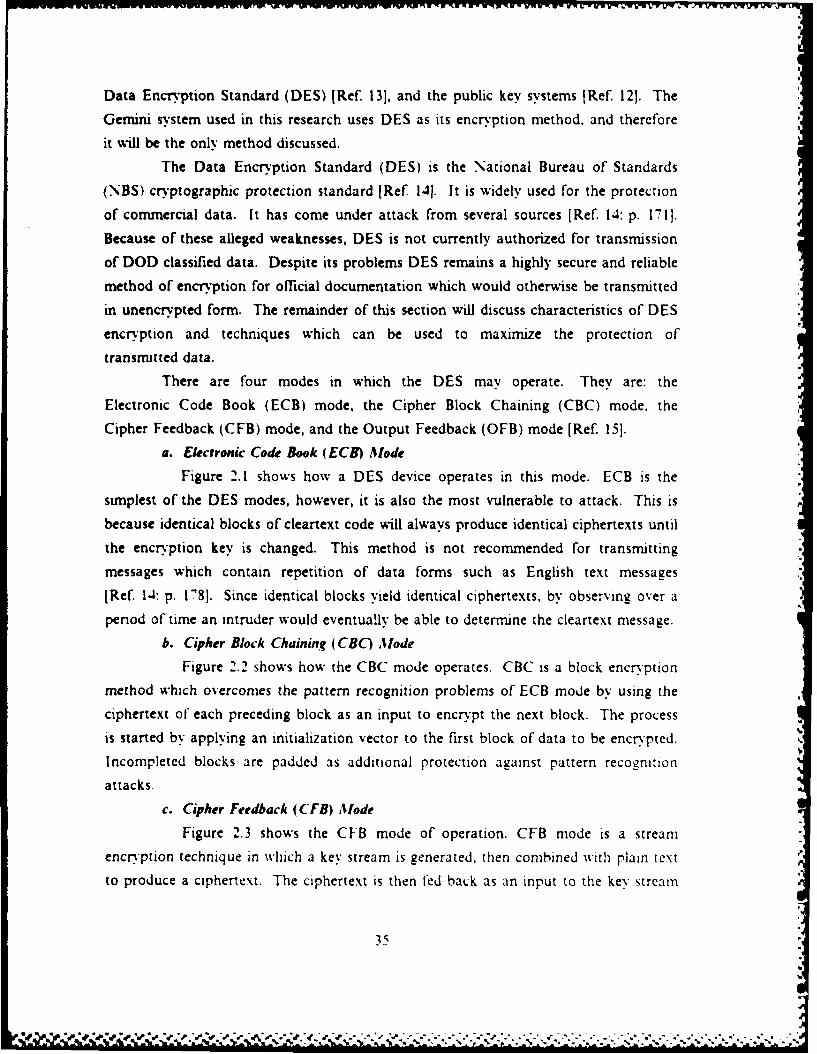
Data Encryption Standard (DES) [Ref. 13], and the public key systems [Ref. 12]. The
Gemini system used in this research uses DES as its encryption method, and therefore
it will be the only method discussed.
The Data Encryption Standard (DES) is the National Bureau of Standards
(NBS) cryptographic protection standard [Ref 14]. It is widely used for the protection
of commercial data. It has come under attack from several sources [Ref. 14: p. 171].
Because of these alleged weaknesses, DES is not currently authorized for transmission
of DOD classified data. Despite its problems DES remains a highly secure and reliable
method of encryption for official documentation which would otherwise be transmitted
in unencrypted form. The remainder of this section will discuss characteristics of DES
encryption and techniques which can be used to maximize the protection of
transmitted data.
There are four modes in which the DES may operate. They are: the
Electronic Code Book (ECB) mode, the Cipher Block Chaining (CBC) mode. the
Cipher Feedback (CFB) mode, and the Output Feedback (OFB) mode [Ref. 15].
a. Electronic Code Book (ECH) Mode
Figure 2.1 shows how a DES device operates in this mode. ECB is the
simplest of the DES modes, however, it is also the most vulnerable to attack. This is
because identical blocks of cleartext code will always produce identical ciphertexts until
the encryption key is changed. This method is not recommended for transmitting
messages which contain repetition of data forms such as English text messages
[Ref. 1-4: p. 178]. Since identical blocks yield identical ciphertexts, by observing over a
period of time an intruder would eventually be able to determine the cleartext message.
b. Cipher Block Chaining (CBC) Mode
Figure 2.2 shows how the CBC mode operates. CBC is a block encryption
method which overcomes the pattern recognition problems of ECB mode by using the
ciphertext of each preceding block as an input to encrypt the next block. The process
is started by applying an initialization vector to the first block of data to be encrypted.
Incompleted blocks are padded as additional protection against pattern recognition
attacks.c. Cipher Feedback (CFB) Mode
Figure 2.3 shows the CFB mode of operation. CFB mode is a stream
encryption technique in which a key stream is generated, then combined with plain text
to produce a ciphertext. The ciphertext is then fed back as an input to the key stream
35
Lim

0 Clstnext
I lSI ,m ,=Key E64Bit Blocks
4 t
Figure 2.1 ECB Mode of DES Encryption.
generation process. Stream ciphers are in general slower than block ciphers [Re. 16: p.
1511. and are not used when large throughputs are required.
d. Output Feedb"a (0 FR) Mtode
The OFB mode is also a stream encryption method. In this method the
key stream is completely independent of the plaintext and ciphertext streams. This
eliminates the problem of error propagation and would seem to be a definite
advantage. However, some degree of error propagation is required to detect message
modification attacks [Ref. 16: p. 149]. As a result, OFB mode is not normally used in
secure network environments. This mode is not implemented on the Gemnini system's
hardware encryption device because it is not self synchronizing.
The interface being developed in this thesis can best be implemented us'ing
the CBC mode of DES encry,.ption. The systcm must be capable of quickly handling
large volumes of data (large throughput), as well as official correspondence.
4. Summary
Assuming that the guard system works as described and it is interposed
between TCO and other Tactical Data S% .stems, this approach has several interesting
36
.% Vn .%i * '

TRANSMI7TER
* 4
IV Block I Bock2 Block3
- - - - - - - - - --
B1 It
RECEN
4 I
Figure 2.2 CBC Mode of DES Encry'ption.
properties with respect to multilevel security. First, no failure or compronuse of t
hardware or programs in the TCO will permit data to spill from TCO to any other
sy'stem. Second, no manipulation of TCO or its processor will release information
across the guard interface. This is because the guard interface will be designed to onlydeal with TCO messages, and to escape the guard. a cryptograph'ic checksumn is
recomputed before release of any message. If this checksum does not identically match
37
* 4
* "I / ! " ." # / . ,.,,J" ., . -.a" ,r ""o . ""/ , ''',",. ,""°"'"""o . . . . ,t . ,,"° "", . ","' ,.

Transmitter Receiver*----------------------------------- -------------------Cleartext
I . [, I ~ oI I * I I II I I ! IKey DES IDES Key
Discard- D sc r -
Cleartext Ciphertext Cleartext
Figure 2.3 CFB Mode of DES Encryption.
the checksum computed when the message entered TCO, the message does not Let
released.The guard can be designed in such a way as to permit TCO to test the correct
operation of the guard by addressing various kinds of messages to itself. The only
records that should return are those whose checksum is properly computed andrecomputed. If there is a concern that an attacker could use this facility to generate
and test checksums, It mig~ht be noted that it would take about .5S.494 y'ear~s tosystematically try all possible 264 checksumns agzainst a single record. At the rate of
10,000,000 trials,,second on average, one could expect to ind the correct checksum inone half the time, or D9,247 years Dsca
B. GEMINI TRUSTED MULTIPLE MICROCOMPUTER BASE1. Description of Gemini System Components
The Gemini Trusted Microcomputer Base is one of the systems currently
being evaluated by the National Computer Security Center for certification at the 3
(Ref 31 level of classification. Until recently, lack of evaluation criteria. as well as,microprocesso technology, made construction of such systems impractical. The
foundation upon which all trusted computer systems are developed is the securit
kernel. The Gemini system employs the latest technology in both hardware and
software engineering. Some of its major features are:
38

* The capability to operate up to eight Intel iAPX-286 microcomputers. inearalet. This provides tremendous processing power, while communicating
through shared memory increases throughput.
The Gemini system is extremely flexible with regard to the types of peripheraldevices which may be connected to the Multibus. These incluile fixed a rd disk,removable disk, find high density floppy diskette drives, as well as, non-volatilememory devices. A maximum of eigt devices may be attached to each RS-232110 interface board.
, With its multiple microcomputers,. the Gemini system supports a varietv ofmultiprocessing and multiprogrammng applications. Processes can be pipelinedto a single processor, or distrouted in parallel among several processors.
Other features include a NBS DES chip encrption device real-time clock, andnon-volatile memory to protect passwords and encryption keys. [Ref. 171
The Gemini system also provides a self-hosting environment for software
development [Ref. 17: p. 41. This allows users to develop applications software.
Gemini supports several advanced programming languages for development. These
include JANUS/ADA, PASCAL, and C. Because of the secure environment, not all
standard constructs are supported, especially in the input/output area. Becausecommunications to and from devices require special formats, utility libraries are
provided with the system containing routines which put calling arguments in the proper
format for use in GEMSOS.
A major attraction for the Gemini system is its tremendous potential for
growth. Its ability to handle a variety of hardware configurations is especially valuable
in DOD applications where a trusted computer system may be required to
communicate with systems using different protocols and hardware interfaces. When
used as proposed in this thesis as a guard between two untrusted systems, the Gemini
system could potentially communicate with a variety of communications devices using
different 1,10 ports.
2. Gemini Resource Management OverviewThe Gemini Secure Operating System (GEMSOS) kernel is logically divided
into three management areas. These are: segment management, process management,
and device management. Management functions are invoked by initiating a GEMSOS
service call [Ref. 17: p. 5]. The formats for calling arguments are found in the'
GEMSOS interface libraries provided with Gemini's software development tools.
a. Segment Management
All data used in the GEMSOS environment is contained in segments. Theapplications programmer is mainly concerned with code segments, stack segments, and
data segments. Bootstrap and kernel segments normally do not change when
39
, ,",,.,,
developing basic applications software. There are eight segment management
functions. A discussion of how to initiate these service calls is contained in
[Ref. 20: pp. 16-28]. Segments can also be managed in groups. Secondary storage
devices are represented by volumes which can be identified as separate entities to a
calling process. Volumes and individual segments can be brought into the address
space of the calling process by using resource management service calls.
b. Process Management
Through process management functions the Gemini system is able to
support a full range of multiprogramming and multiprocessing applications. Each
process is uniquely identified by code, stack, and data segments. Once created the
process can be synchronized to run simultaneously with other processes using one of
two methods. Eventcounts and sequencers were selected over other techniques because
they are particularly well suited to operation in a secure environment [Ref. 17: p. 6].
All segments created in an applications program are assigned an eventcount and
sequencer automatically. Process management calls to these devices allow the
programmer to coordinate process functioning while maintaining access security.
c. Device Management
The third management area is device management. The Gemini approach
to device management is to minimize the size of the security kernel code by reassigning
device management functions to application level code whenever possible [Ref. 17: p.
91. This has two effects. Reducing the size of the kernel makes verification easier.
*however it also makes writing applications software more difficult. Traditional input
and output files are replaced by segments which can be read from or written into.
Devices are attached and detached to allow them to be used by more than one calling
process. Process synchronization primitives are used to control access to the segments
made available to an attached device. The 1,0 device controller is treated as a process,
which is then synchronized with the available segment eventcounts or sequencers to
perform the required device management functions. Additional information concerning
Gemini resource management functions is contained in [Ref. 17: pp. 5-10].
3. Gemini Secure Operating System (GEMSOS) Architecture
The Gemini system uses four hierarchical rings to implement its security
structure. Ring 0 provides the most security, while ring 3 is least secure. It can
support both discretionary and mandatory policies. The mandatory policy is contained
in ring 0. This policy cannot be modified. Ring I is used to control the discretionary
40
. 7 . ' ,' ''.". : . ; . .-, :, . -.V '.-. .. .:. . -. . -. ". . . . . .. '. / . ' , . . -.. -' ... .." ..". - "

or 'need-to-know' policy, supervise the use of the data encryption device, and support
other security functions not contained in the mandatory policy. Ring 2 and 3 are
available to the programmer for use in developing applications software. The security
mechanism which coordinates inter-ring communications involves the control of access
to subjects and objects. A subject is a process which is allowed to operate over a
specific domain within the system. An object is a specific piece of information which is
assigned a security label. All access between subjects and objects is controlled by the
GEMSOS security kernel located in ring 0. Approval is based on comparison of the
security labels of the two entities trying to gain access.
Compromise Properties:
1) If a subject has "observe" access to an object, the compromiseaccess component of the subject must dormnate the compromiseaccess component of the object.
2) If a subject has "modify" access to an object. the compromiseaccess component of the object must dominate the compromiseaccess component of the subject.
Integrity Properties:
1) If a subject has "modify" access to an object then the integrityaccess component of the subject dominates the integrity accesscomponent of the object.
2) If the subject has "observe" access to an object, then the integrityaccess component of the object dominates the integrity access .component of the subject.
Figure 2.4 Compromise and Integrity Properties.
Security labels are used to identify the access class of all subjects and objects.
The access class is further broken into a compromise (observe) level and an intearity
(modify) level. Compromise and integrity protection are based on strict properties
which must be observed in order for access to be granted. Figure 2.4 is taken from
[Ref. 17: pp. 16,171, and contains a simplified statement of these properties.
Domination as stated in these properties means that the level of the access component
is greater than or equal to the entity it is trying to observe or modify.
41
7. ..

S-Y..lr, . I%.-W
Compromise protection property I is a traditional security policy. It states
that in order to observe information, you must have a clearance equal to or greater
than the information you want to observe. The second property is more subtle. This
property prevents, for example, a secret user from modifying a file which could be
viewed by a confidential user. This property is especially important in prevention of
'Trojan horse' type attacks [Ref. 18: pp. 65-691. The integrity protection properties are
similar to the compromise properties except that they refer to the ability to modify
information. Property I states that in order to modify a confidential document, you
must have at least a confidential integrity level. The second integrity property
prevents, for example, a secret user from observing (and possibly being influenced by)
information which could be modified by someone at a lower integrity level.
In addition to the access class integrity described above, the Gemini system
also employs ring integrity. Ring integrity means that subjects at a certain level can
only access objects of the same, or higher ring number. This policy reinforces the
hierarchical structure of the GEMSOS rings.
These compromise and integrity policies are further complicated by the fact
that the Gemini system is a multilevel system. This means that both users and
resources may have clearance to access a range of security levels. Multilevel subjects
are potentially very dangerous because within their range of operation they are not
subject to the second compromise and integrity protection properties [Ref. 17: p. 20].
It is up to the applications programmer to ensure that he does not create subjects
which will allow violation of these properties. This is especially important when
interfacing with devices. Figure 2.5 is taken from [Ref. 17: pp. 21,22], and represents a
summary of the security properties of single and multilevel devices.
Device access levels refer to the physical security of the environment in which
the device is going to operate. This is separate from the security level of the process
which is attempting to communicate with the device. For example, a terminal located
in an unsecure room with an unclassified device access level, cannot receive
information from a secr& process. The term single level device implies that the
maximum and minimum access classes for the device are the same. In multilevel
devices the access classes are different, and represent the range over which the device is
allowed to operate.
42

iw w uw W%r~nfuWuW mu-'iV Wr WUam 1UM% WU WWJWTWFW FJrJVW % -wu wY' UK:
Single Level Devices:
1) To receive ("read") information:process maximum compromise > = device minimum compromisedevice maximum integrity > = process minimum integrity
2) To send ("write") information:device maximum compromse > = process mnummum compromiseprocess minimum integrity > = device minimum integrity
Multilevel Devices:
1) To rec,;ive ("read") information:process maximum compromise > = device maximum compromisedevice minimum integrity > = process minimum integrity
2) To send ("write " ) information:device minimum compromise > = process minimum compromiseprocess maximum integrity > = device maximum integrity
Figure 2.5 Single and Multilevel Device Properties.
4. Application Development Environment
a. General Description
This section provides the foundation for the necessary steps to develop
software for the Gemini system. It is important because it provides the basic
components that are needed for applications development. This provides a bridge
between the applications programmer and the operating system primitives to allow
development of reliable software.
The objective of this section is to present an ordered method of developingapplication software within the GEMSOS environment. It should be considered as a
guide and not as a fixed set of rules. The facts considered here are taken from
[Ref. 201.
b. Hierarchical Storage Structure
The Gemini system provides a one-level secondary storage system for
information. File concepts are not supported by Gemini. Instead, segments are used
which are considered as objects having logical attributes related to them (i.e., security).
Each segment has a maximum size of 64 K bytes. The segments are handled by the
43
v.

WMw1d w, -V
system as a hierarchy, where each segment is identified by a unique path namecorresponding to the index of an entry in the Location Description Table (LDT) of theprocess that creates and/or uses that segment.
The representation of segments follow a hierarchical structure in which theroot is the system root (transparent to the user) and the whole collection of segments is
assembled as an inverted tree. Each application program becomes part of thehierarchical structure and is statically created at system generation time using a system
submit file as explained in [Ref. 19].
System generation consists of creating a hierarchical structure of allsegments known to the system at system runtime. It is basically the inclusion of thesegment hierarchy of the application program into the GEMSOS hierarchy. This isaccomplished by using segments declared in the submit file. Figure 2.6 shows a typical
hierarchical structure representing the segments that GEMSOS requires to runapplications. This structure is fixed and must be considered in the development of anytP
application program. Figure 2.7 shows the addition of segments necessary to execute a r
specific application. Entry 5 in the hierarchical structure is always dedicated as the Zmentor (or root) of user applications. This entry is the mentor of all the segments thatare needed to implement the upper levels of the system application program. Under
the Gemini concept, a segment can support up to 12 descendents numbered from 0 to
I I. To support this concept there is a volume aliasing table (VAT) or volume mentorthat relates the segments to their mentors [Ref. 19: p. 21.
When a segment is used by a process, it must be deleted before it can be
made available for another process. The numbers indicated in both Figures 2.6 and 2.7correspond to entry numbers of segments associated with a mentor (from 0 to 11);segment numbers have a different enumeration which corresponds to their entries inthe LDT. Each segment in the system has a unique path name that identifies it, but
not by the application process. Instead, a process-local segment number is used.When two processes share the same segment, each one recognizes the segment by a
different segment number assigned in its own LDT.
For example, in Figure 2.7 the path 5,7 corresponds to a segment thatholds the code for a child application program and must be declared in the submit file.Entry 5 is the mentor for entry 7. This creation is static and the path indicated mustbe known in the application program. On the other hand, the path 5.5,7 is used to
hold data and will be created dynamically during execution of the application program.A more complete explanation is presented in [Ref. 19].
44

System
SSAT V1LOADER VILOADER RITRAP NVDSCODE STACK CODE (APPLICATION
NV.DS V1 LOGIN APPLICATIONCODE CODE
Figure 2.6 GEMSOS Hierarchical Structure.
c. 110 Device Assignment
The process of attaching devices must be accomplished before an I 0
device becomes known to the system. This involves assigning a logical process to the
1, 0 device so that the device is known by the process. The process then contains the
device drivers to allow it to manipulate the device. A device may be declared as either
a read (input) or write (output) device, as part of the information provided to the
"ATTACH" primitive call in GEMSOS [Ref. 20: pp. 43-44). A device may be attached
to only one process at a time. An error will occur if an attempt is made to attach a
device by more than one process. The inverse primitive is called "DETACH" device.
This primitive detaches the associated process and the device becomes available for
further assignment [Ref. 20: p. 451.
45

Mentor
HV.DS
0 1 2 3 4 5 APPLICATION . 1
SSAT VILOADER VILOADER RITRAP
NV.DS V1LOGIN APPLICATION Mentor CHILD
CHILD CHILD
STACK DATA
Figure 2.7 GEMSOS Hierarchical Structure Including an Application.
d. Process Creation
This section describes the steps that should be considered when creating a
process. One process is created from another. The creator is known as the "parent"and the created process is known as the "child". The child process receives its
resources from the parent. Each process is a collection of segments known to thatprocess and managed using primitive functions or "calls" provided by the system. Anaddress space is created to hold a segment and an application programmer must make
use of GEMSOS primitives for the creation and use of address spaces.
The sequence of steps that must be followed in order to create a processstarts with the "CREATE" primitive. When this primitive is called anaddress space is
created for that segment. The next step links the address space with a specific process,
46

i.e., a recognition of the segment by the process as an entry in its Local Description
Table (LDT). The result is the identification of this address space with a segment
number. The primitive used for this is the "MAKEKNOWN" primitive.
The last step is related to the use of this segment--a segment must be in
main memory in order to be used. This function is performed using the primitive
"SWAP-IN", which loads the segment from secondary storage into main memory.When the segment is no longer needed by the process, an inverse action
must be performed in order to release the space used by the segment. As in the
procedure described above, a logical sequence of steps must be followed, starting with
the release of the memory used by the segment. This is performed by the "SWAP-
OUT" primitive in which the segment is written back out to secondary storage. The
next step is the elimination of the association of the segment and the process.
Elimination of a segment from a process' address space is performed by the
"TERMINATE" primitive, which breaks the association and makes the entry number
used in the LDT of the process.
The final step is total removal of the segment from the system address
space. This is accomplished by the "DELETE" primitive. The result is the removal of
the segment from the system and the return of the address space to system resources.
e. Process lanagement
Because a process is a collection of segments, segment creation is an
important step that should be considered during process creation. Each segment has
its own attributes which are specified in a segment structure record and then declared
in a "CREATE SEGMENT" primitive. The segment is created with the specified
attributes and the addition of a new branch in the hierarchical structure is made
[Ref. 20: pp. 20-211. The inverse action is the "DELETESEGMENT" call, where a
segment previously created is now removed from the hierarchical structure [Ref. 20: p.
22]. This call is used when a process finishes its execution because segments are not
automatically removed.f. Mfakeknownl Terminate Segment
The "MAKEKNOWNSEGMENT" call adds the specified segment to the
address space of the calling process [Ref. 20: pp. 23-25]. Like all of the primitives it
has its own record structure, which must be initialized with the pathname that the
segments will use in the hierarchical structure. The inverse call.
"TERMINATE SEGMENT" eliminates the pathname from the hierarchical structure
and frees the segment number from the LDT table [Ref. 20: p. 26].
47
g. Swapin/Swapout Segment
A segment is created in secondary storage by first using the primitive
"SWAPIN_SEGMENT," to provide main memory space for the new segment.
"SWAPOUTSEGMENT" is used to write a segment from main memory to secondary
storage. [Ref. 20: pp. 27-28]
h. Synchronization
Synchronization among processes is maintained by the use of eventcounts
and sequencers (Ref. 21: pp 115-.1241. Segments used to control synchronization must
be common to all of the processes involved in that synchronization. An eventcount ismaintained by an integer counter under control of the cooperating process.
Completion of an operation (event) is signaled by incrementing the eventcount. Theupdated eventcount provides a signal to a waiting process that the operation is
complete. The primitives used are described in [Ref. 20: pp. 37-411.5. Summary
The Gemini Trusted Multiple Microcomputer Base is an extremely capable
computer system which combines state-of-the-art technology with a high degree of
flexibility to handle a variety of possible applications. Its multiple processor and
multiprogramming configurations are valuable assets when functioning as a secure
guard interface between two untrusted systems as proposed by this thesis. Its ability to
simultaneously handle devices with different protocol requirements and security levels
could potentially eliminate the need for time consuming review and sanitation of
information for transfer between Tactical Data Systems.
'4
48
.L

III. DEVELOPMENT OF A MULTILEVEL SECURE INTERFACE
A. GENERAL
1. Objectives
The objective of this research is to develop a simple interface which will
demonstrate how the Gemini Trusted Multiple Microcomputer Base may be effectively
used as a trusted computing base (TCB) linking untrusted command and control
systems. There are four major phases in the development of the system:
I) )emonstrate the transportability of the JINTACCS Automated MessageProcessing System CJAM.PS) software to the Gemini Multiprocessing SecureOperating System (GEMSOS).
2) Demonstrate the inter-sepment linkage for the use of multiple languageapplications programs andltibrares for use with GEMSOS.
3) Establish two way communications between users at remote terminals usingthe Gemini systerfm as a secure communications interface.
4') Demonstrate the use of Gemini security mechanisms to prevent unauthorizedaccess to sensitive information.
The Air Force JINTACCS Program Office in Langley, Virginia and MITRE
Corporation are currently working jointly to develop an automated, JINTACCS
format, message preparation system. This system is the Joint Interoperability of
Tactical Command and Control Systems (JINTACCS) Automated Message
Preparation System (JAMPS). JINTACCS was established by the Joint Chiefs of Staff
(JCS) so that the military services could have a common standard for communicatingduring joint operations. JAMPS is a software package developed to automate the
preparation of these JINTACCS-standardized messages. The first phase of thisresearch is to demonstrate the transportability of the JAMPS software to the Gemini
Multilevel Secure Operating System (GEMSOS) in order to have JAMPS operate in a
multilevel secure environment allowing automation of JINTACCS message preparation
for communication between systems.
The Gemini system provides a self-hosting environment for software
development and provides development environments in several languages to include
PASCAL, C, and ADA. The second phase of this thesis is to develop applications
using more than one programming language to display the intersegment linkage of the
multi-language gates provided with GEM SOS and the flexibility of the Geminiapplication development environment. The intention is to demonstrate the use o"
49
_-'. .t ' r.¢' .et,"N ,.o ' o,,.' ,' .€ . . . o .%.'% - '_'%€ 4' . . . . .- .. .o-= - -."o =.-=- •. - - o.-.-.-o ..-j ", -. ., - == . .,•.

ADA in a secure environment and to show the capability that GEMSOS has for
linking multiple languages. The languages used are PASCAL MT-86 and Janus
ADA. The Janus ADA environment has not been completely developed for use with
GEMSOS and a secure environment, specifically not all ADA constructs are supported
in the GEMSOS environment. The majority of the modifications occur in the
input/,output area. Because communications to and from devices require special
formats in a secure environment, Gemini provides utility libraries which put these calls
in the proper format. Currently, these utility libraries are well developed for the
PASCAL language. The goal of the second phase of this research is to demonstrate
the flexibility of GEMSOS by writing segments of code in PASCAL and ADA using
inter-segment linkage to have the system manager, a trusted process written in
PASCAL, call and control multiple TDS terminal utility processes, written in both
PASCAL and ADA while maintaining the rules of compromise and integrity required
in the GEMSOS secure environment.
In order to create a realistic communications link, it is necessary to simulate
having untrusted computer systems communicating with each other. This is
accomplished by having the Gemini system communicate with itself using separate 1:0
ports. By routing the incoming and outgoing traffic from each port to separate
processes, the "multiple computer" environment may be simulated. The interface is
controlled by the multilevel security manager located at a data terminal linked to the
Gemini system. This security manager is responsible for:
* System start-up and initialization.
* Assigning access levels for other terminals.
• Entering the cryptographic key.
Control of communications to and from the external ports.
• Routing of message traffic to the appropriate terminals.
Each user terminal is assumed to be located in an area which would provide
appropriate physical security for the access level of the terminal. Each may enter
messages. transmit messages, and display incoming messages provided the terminal at
which they are located has the proper access level.
The final goal, to test security of information and access, is demonstrated
using a series of specific configurations and data sets to exercise security mechanisms.
These tests are meant to demonstrate, rather than prove that information security and
integrity are preserved. They are in no way intended to be exhaustive, however. they
allow for a series of observations to be made concerning overall system security.
50

2. Design Constraints
The Gemini system used for the development of this demonstration has 12
ports available for attachment of 1,0 devices. This allows for up to eight user
terminals and the security manager terminal. For this demonstration, only the system
manager terminal and two TDS utility terminals are used for simplicity of design and
testing.
Software constraints are generated by the environment in which this type ofsystem would be used. An assumption is made that when acting as a multilevel trusted
computing base and interface device, the system will most likely be adapted to "off-the-shelf' systems within the Department of Defense (DOD). Systems such as this have
built-in physical and software security attributes. For this reason, no effort is made toprovide security between the Gemini system and the remote terminals other than end-
to-end encryption. This security would be provided by some mechanism other than theTrusted Computing Base (TCB). The lines are assumed to be secure, as are thelocations in which the terminals are used. In order to provide overall system security,
these security measures would have to be verified prior to installation of the trustedcomputer system at a particular activity. Another assumption is that the system
demonstrated may communicate by a variety of means including hard wiring, secureteletype, Autodin, DDN, or satellite communications. For this reason, no specific
protocol was adapted. JINTACCS message processing was used as the message
format, adapted to the Gemini system. Header information and secure labels wereplaced on each message in order to allow transmission over a variety of
communications devices.
3. Summary of Design Decisions
Figure 3.1 shows a block diagram of the proposed system design. Forsimplicity of the demonstration, only three terminals are used. One terminal is used asthe multilevel system manager and the other two simulate untrusted tactical data
systems such as MAGIS/IAC or ATACC. To provide additional flexibility, the accessclass of the untrusted terminal may be changed by the system security manager. The
untrusted terminal may send and receive messages from the trusted computer system,however they must rely on the system security manager to actually transmit the
messages and provide the appropriate security.
It is necessary for the system security manager to create a single level processfor each user terminal attached. Figure 3.1 shows how a single level process is used to
51 '
S . .

VWVW11qrrw1?QFxVw1 - -
System ManagerMultilevelProcess
TOO e-*,00 Ge;iri TrustedSYSTEMMANAGER
(D
DES DESEncrypted CommunicationEncrypted Communication
M ni Trusted Interfa mini Trusted Interia
13
13
Single Level ingle LevelTerminal Utility Terminal Utility
Process Process
TDS TDSTERMINAL TERMINAL
UTILITY UTILITY
Figure 3.1 Proposed Systern Design.
52

provide a buffer to protect information. Even if an attacker were to cause information
of a higher level to be misrouted by the multilevel process. it would still be protected
from compromise by the single level process which interfaces directly with the user
terminal.In order for this design to work there must be synchronization among the
processes. Interprocess communications are synchronized by using eventcounts
[Ref. 22: p. 20]. Although the system simulates the link of two separate systems, onlyone multilevel communications process is used to simplify the synchronization
problem. Since the communications processes would be identical this limitation does '"
not adversely impact system design.
B. SYSTEM IMPLEMENTATION
1. Hardware Components
As discussed in the preceding section, the number of data terminals used in the system
was limited for simplicity of design and testing. Figure 3.2 shows the final system
hardware design. Terminal 100 is used by the system security manager to initiate and
coordinate communications via the external communications interface. Remote user
terminals are connected as read'write devices and attached to global serial ports () and
3 of the Gemini computer. This represents untrusted users exchanging information viathe trusted process. The external communications interface is simulated with the use of
a null modem allowing the Gemini computer to communicate with itself. Global serial
ports I and 2 were used for this purpose. A user's guide for this demonstration is5-
provided in Appendix C.
2. Application Program Format "-
Preparing programs to run in the Gemini Multilevel Secure Operating System
(GEM SOS) environment is more complicated than running PASCAL programs in a
nonsecure environment. In order to be accepted by the system they must first be put
into a specific format which can be recognized by GEMSOS in order to gain access to
the security kernel. There are several software tools which can speed up the process of
preparing a program to be run in the secure environment. The flact that a program
compiles successfully does not necessarily mean that it will run in the GEMSOS
environment. For a PASCAL program, following compilation, the program is linked
to the appropriate modules using a file named, 'applicationname.KMD' [Ref. 23].
This file contains a formatted list of the modules with which the application segment
53
L:5
'.5
.-- . . " . ) . " . . " . ." . . . . . - . .- , .- . . .- - . - . - - . . - . . - . . . , - - - . . . ,, - . . - % .' , ". " . .

.vvw . KwvvLW

needs to be linked. The result of the linking process is a file namedIapplication name.CMD' which still has no security classification assigned. To assign
security classification, and prepare the program to execute in the secure environment, a
secure volume must be created by running the operating system generation (SYSGEN)
program.
When developing a JanusADA application which is to run on GEMSOS, 3
main points must be kept in mind:" Standarm Janus/ADA I/O file type utilities cannot be used, GEMSOS kernel
calls must be made instead.• The first statement in an. application program must be a function call to the
get rI def function. This unction returns the ring 1 process definition recordwc-h is required for subsequent kernel calls.
* All anlpications must be linked with the "/c80" option, for example "JLINKTDS ru80."
To assign security classification, and prepare the program to execute in the secure
environment, a secure volume must be created in the same manner as mentioned above
using the SYSGEN program.
Executing the SYSGEN program includes the application program in a
segment structure which is then transformed into a "bootable system structure on
formatted volumes." [Ref. 19: p. 1] Detailed procedures for using the SYSGEN
program are contained in [Ref. 19: p. 7-201. The key to proper use of the SYSGEN
program is identifying the segment structure in which the application segment will be
placed. The segment structure includes the boot-strap, kernel, application code, and
data segments. The easiest way to identify this segment structure is to include it in a
submit file named 'application name.SSB.' For basic application programs, the
segment structure does not change. Use of the submit (.SSB) file eliminates the need
to enter the segment structure interactively each time the operating system generation
program is run. Use of the SYSGEN submit mode is further explained in [Ref. 19: p.
9-14]. The submit file used for system generation of this demonstration (GUARD.SSB)
is provided in Appendix M.
C. SYSTEM SOFTWARE DESIGN
1. Application Segment Development
Application software for this system was developed using modular
programming construction techniques. This allowed for independent testing of each
module prior to its inclusion in the main program. This technique was especially usel'ul
55

because trouble-shooting GEMSOS related Ring 0 service calls can be difficult for newusers. Processes were developed as application code segments. They are:
1) multilevel system manager process (PASCAL MT + 86)2) single level terminal utility process (PASCAL MT+ 86)
3) single level terminal utility process (Janus ADA)
Each process was developed as an independent application code segment. Thesingle level terminal utility segment may be assigned different access levels by thesystem manager to demonstrate the interface to more than one system.
a. System Manager Segment
The system manager segment controls system configuration, dataencryption, and communications through the external communications ports. Figure3.3 shows a flow diagram of how this segment is constructed. A detailed source listingof the code implementation is contained in Appendix D.
Creation of a child process requires completion of four record structures.Each record structure has several entries. Each entry is completed in a specific orderwhich builds to the 'CREATEPROCESS' resource management call. Detailed
instructions for process creation and record entry format are found in [Ref. 20].Segment and process management are the most difficult concepts for someone
unfamiliar with secure computer systems to grasp. The procedure developed in thissegment could be used as a model for process creation in other programs. The specificentries may vary, however, the physical structure of the procedure is general enough to
fit a variety of applications.
The system security manager located at terminal 0 has direct control oversystem assets. To provide this control, the system manager has the option of
specifying (within predefined limits) how the system will operate. These parameters areentered when the system is initialized. They are interactively entered into a system
operator record from which they can be drawn when required by other procedures.Parameters which do not need to be directly controlled by the system manager are
fixed and cannot be directly accessed.
b. Terminal Utility Segments
As discussed earlier in this chapter the user terminals can input, transmit,and display messages. Each terminal is a single level device capable of sending andreceiving messages of the same level. Figure 3.4 shows a flow diagram for the terminalutility application segment. The actual code for the programs which implement this
56
../. .....: ....- ..,.-. .-. • . . . - . ... -.-.-. . -.-. -. . . . . . . . . ".. . -. .- - - - ,.- - - -,e - -,l

START
INPUTPARAMETERS
r Comm &CRYPTO TEST
SOURE O I MORlEC YSOUC NERROR j TEMNSSGDETNTO
AWAIT
MAKRE OFSIECV DOESIAIN
ERROR MSG 4 VIOLATION INCOMING MSG
Figure 3.3 Systemn Manager Flow Chart.
57

flow diagram is contained in Appendices H through L. This program is activated when
the terminal process is created by the system manager process.
All messages sent and received at the terminal are stored in a speciallydesigrated message buffer segment. Access to this segment is shared by the user
terminal and the system manager process. Each terminal has its own message buffer
segment, and cannot access the other's segment without going through the system
manager process. When the user has completed his message transactions, he initiates alogoff procedure. The logoff procedure deletes the terminal process and returns the
resources allocated to the process to the system manager process which created it.
These include memory space, process local segment numbers, and any attached devices.
c. Program Documentation
Each module in the application segments has a header describing itspurpose and general operation. The intent was to provide clear programs which could
be used as a basis for future research. In some cases this meant sacrificing efficiency
in order to provide better clarity.
2. Process SynchronizationProcess synchronization was accomplished using the eventcount of the
message buffer segments of each terminal process created by the multilevel system
manager. By advancing the proper stack eventcount the terminal process alerts the
system manager that it is ready to begin message processing. The terminal advances
the outgoing message buffer segment eventcount to notify the system manager process
when it desires to transmit a message or when it has completed processing. When a
terminal process indicates that it desires to transmit a message, the system managertransmits the message, and then unblocks the other terminal process to display the
incoming message by advancing its incoming message buffer eventcount. This processcan be continued indefinitely. The actual implementation of this sequencing is further
explained in the applications code segment listings contained in Appendix D.
D. DESIGN SUMMARY
This chapter has discussed the ;ystem design process in terms of- its objectivesand limitations. The resulting hardwire and software configuration was implemented
using modular construction techniques which greatly reduced the number of software
errors.
58
* ..... *.. % .. .* * .% %,.

aflO flfl ~ fl W~flLr ~.W~~flfflr il IN~f NilSF R af wdl S T~AT
DISPLYLDYMOE NTYA
BUFFE SUFER SFFERMEIL
FiueI.STrinPLiAtYFo Cat
1 7 L0 xI
**Mv 4 .*IT. DIPA TRNSI L-. -~
The resulting system uses the Gemini as a secure communications interface andmessage processing facility. All communications are protected to the maximum extentpossible using the Data Encryption Standard (DES) algorithm in the cipher blockchaining (CBC) mode. Terminal processes are assigned single level access whichprevents a user from gaining unauthorized access to classified information by allowingthe kernel to enforce the rules of integrity (authorization to write) and compromise
(authorization to read).
60
IV. DISCUSSION OF RESULTS
A. SYSTEM OPERATION
The model communication system developed in this thesis to demonstrate using
the Gemini Trusted Multiple Microcomputer Base as a secure interface for data
communications met or exceeded all design goals. Messages were passed between
tactical data systems in a manner that ensured security from unauthorized access at
both source and destination. Data encryption was used to maximize the security of the
transmitted data. Finally, by varying the access class of the terminal processes it was
possible to demonstrate the system's ability to detect and respond to security
violations. Flexibility in determining system configuration allows modification of
system parameters to meet a variety of test requirements.
System operation is initiated and controlled by the system manager. The
multilevel system manager process creates the single level TDS processes at access
levels based on two separate controls. First, the Gemini computer used for testing and
evaluating the interface was configured to allow classification of the serial input,' output
ports. This means that the operating system, specifically the kernel, recognized the
maximum access level of each serial port. This process was completed by burning the
machine PROM specifying that each port had a maximum access level. The second
control measure was accomplished by allowing the multilevel system manager to
specify an access class at or below the maximum allowed by the serial port. Based on
these constraints, a TDS terminal may only display messages created at or below its
access level (enforcing the compromise level, authorization to read) and send messages
to other terminals at or above its access level (enforcing the integrity level,
authorization to write). It is important to note that, for this demonstration, the user
does not assign the classification of the outgoing message. Message classification is
assigned by the system manager according to the access level of the TDS sending the
message. All security checks are performed within the multilevel system manager
process to strictly enforce the security policy established for that system. To facilitate
security testing, the TDS access levels in this demonstration are manually entered by
the system manager. (If a local commander did not want to leave this choice up to the
system manager, the access level information could be hidden in a File that he does not
61
-r %e
* _.I ", : :X /-:--=- .... ,'. .;.-.--,, '.,.'.., .- '-'-. ... ;. -.- ".'-'.:.:-. ".' ," . -

have access to, or simply left as configured on the system PROM (built into the
hardware). Once started, the system operates independently. This eliminates the
possibility of a system manager manually misrouting information stored in the message
buffers.
One potential problem was the possibility that an unclassified user could enter
classified information in an unclassified message and transmit it to an accomplice who
had tapped into the external communications line. To help prevent this, the outgoing
message is encrypted using keys which are inserted by the system manager. Possible
compromise of the key could further be prevented by having the key entered by
someone other than the system manager or by a hardware key generation device. The
goal was to develop a process which would demonstrate the enforcement of basic
computer security measures and provide a baseline understanding of this technology
and its application in a tactical command and control system. There are a wide variety
of possible system configurations. Selection of a particular configuration would have
to be based on the security policy of the particular command and its associated
security requirements.
B. DEVELOPMENTAL PHASES
1. JINTACCS Automated Message Preparation System Implementation
a. Discussion
JAMPS is a portable set of computer controlled equipment for assisting
operators in composing and exchanging JINTACCS messages. It provides one or
more operators a work station for composing communications messages over an
external link. Each work station provides the capability to store and retrieve messages
composed at the work station and messages received via external communications.
The original intent of this thesis was to completely integrate the JAMPS software into
a secure environment within and controlled by the Gemini Trusted Computer. After
close review it was determined that total integration of JAMPS was beyond the scope
of this thesis and further study is recommended in the area of transporting JAMPS into
the GEMSOS environment. JAMPS is used, however, in this thesis as a controlled
process by each of the TDS terminal utilities as the mechanism for creation of
messages used in the communication process.
62

b. Compromise Design
The primary objective of this thesis remains the same, except that the
JAMPS software was not transported onto the Gemini computer. The JAMPS
procedure is, however, controlled by the TDS terminal utility process. Figure 4.1
depicts the hardware configuration showing a personal computer running the JAMPS
software attached to the Gemini computer as a write device of the same access class as
its controlling TDS. This actually creates a multi-terminal workstation with the PC
running the JAMPS software and transmitting JINTACCS formatted messages with
appropriate compromise and integrity rules enforced by the Trusted Computing Base
(TCB).
Each of the TDS workstations consists of a terminal and a personal
computer and may be configured with a printer for hard copies of transmitted and
received messages. Each element of the workstation would have the same access class
and therefore would be controlled by the system manager for enforcement of security.
It is recommended that a project be undertaken to transport the JAMPS
software onto the Gemini Trusted Computing Base to eliminate the need for the
additional PC and to have the message preparation process completely controlled by
the TCB rather than attaching it as an untrusted process.
2. Intersegment Linkage of Multiple Language Applications
The Gemini multiple microcomputer system is a self-hosting environment for
software development using the CP/M-86 operating system. Any programming
language that runs on CP'M-86 potentially can be used to develop concurrent
computing and multilevel secure application software. Gemini is currently supporting
the following languages: PASCAL MT+, Janus/ADA. PLI, C, and FORTRAN.
Additional software development tools are provided by several utility programs
supplied as a part of the Gemini applications development package. Currently, the
PASCAL MT+ applications development environment is the most thoroughly
developed. This environment contains libraries of ring 0 and ring I calls and routines.
The other languages have been supported fbr specific Gemini clients. An important
aspect of this thesis was a demonstration of the use of ADA in a secure environment,
therefore, the application development package provided by Gemini needed to be
updated and more completely developed to support this project. As a result, additional
libraries have been developed to support the ring 0 and ring I calls for Janus ADA to
bring applications support to a level comparable with PASCAL NIT+. These libraries
are listed in Appendices I and J.
63
k ,V N.* N V% %
VL. k .- 1 . li 'k. j iil. li-,ii.,,1~,,~iii, M i 'l ,* l *
I ' - ... ."

Figure ~ ~ ~ ~ ~ ~ Nl 4.Meie -ad r ofgrto.m
TC64
System.

All information in a Gemini system is contained in discrete, logical objects
called segments. Each segment has an access class that reflects the sensitivity of
information contained in the segment. Segments may be simultaneously shared by
multiple subjects, but access to the segment on the part of each subject is controlled by
the relationship between the segment's access class and each subject's access class.
Every segment in GEMSOS has a unique identifier. This identifier is
effectively different for every segment ever created in any Gemini system. Unique
identifiers are used to prevent "spoofing" of the system by substituting one segment for
another.
Different languages pass information and identifiers to segments in different
formats and using different protocols. Assembly routines can be used to "translate" the
information and protocols in order for subjects created in different languages to access
shared segments. This inter-segment linkage is necessary in the secure GEMSOS
environment for the kernel to enforce the security rules in the trusted environment.
The difficulty of inter-segment linkage can be reduced by creating separate
processes in different languages with their own code, stack, and data segments. By
creating separate processes, no assembly routines are required because, once the sourcecode is compiled, it is essentially identical and no protocol or translation is necessary.
The multi-language code segments can be called and implemented without restriction.
The final design included the system manager, a trusted process written in
PASCAL MT+, and untrusted TDS terminal utility processes written in PASCAL
MT+ and Janus ADA. Each TDS terminal utility was accessed and controlled by the
trusted process. Since each TDS utility process was separately compiled and linked,there was no need for an assembly routine to translate information between segments.
Therefore, any language which can be compiled and linked into a CP'M-86environment could be used to create untrusted processes.
3. Communications
In order to create a realistic communications link, it was necessary to simulate
having untrusted computer systems communicating with each other. This wasaccomplished by having the Gemini system communicate with itself using separate 1 0ports. By routing the incoming and outgoing traffic from each port to separate
processes, the "multiple computer" environment could be simulated. The interface was
controlled by the multilevel security manager located at a data terminal linked to the
Gemini system. This security manager was responsible for:* System start-up, initialization and testing.
65

* Assigning access levels for other terminals.
* Entering the cryptographic key.
a Control of communications to and from the external ports.
* Routing of message traffic to the appropriate terminals.
* Enforcing rules of integrity and compromise throughout the communicationsnetwork.
Each TDS terminal was allowed to input JAMPS formatted messages (using
the attached PC running the JAMPS software), transmit messages, and display
incoming messages provided the terminal at which they were located had the proper
access level.
A typical scenario might include:* System startup, login, and initialization.
* Input of parameters such as communications ports, access class for each TDStefninal, and buter sizes.
* Communications and encryption testing.
• Creation of the child process for each TDS terminal.
* Entering the transmit/receive loop.
* Message creation (activation of JAMPS software)
• Message transmission.
• Message display
* Enforcement of security rules and report of security violations.
• Detaching and terminating child processes.
• System shutdown.
Two way communications between TDS terminals could easily be maintained without
error, while ensuring that the rules of integrity and compromise were enforced.
a. System Upgrade
Initially, the Gemini computer installed in the Wargaing, Analysis, and
Research (WAR) laboratory was inadequate for development of a suitable
demonstration of the scope of this thesis. Initial development was done on site at
Gemini Computers in Monterey. Dunng the development of the demonstration it was
determined that a system upgrade. to inciude memory expansion and a global serial
board (consisting of 8 serial ports) was necessary. A machine was configured at
Gemini and used until an upgrade could be accomplished on the Gemini computer in
the wargaing laboratory. Once this upgrade was accomplished the demonstration
developed for this thesis could be modified slightly and used as a working, multilevel
66
% .% .%7............. .-

communications network to support wargarming and research in a multilevel secure
environment.
4. Demonstration of GEMSOS Security Mechanisms
The fourth task of this thesis was to demonstrate how GEMSOS would
enforce security mechanisms to prevent unauthorized access to sensitive information.
To demonstrate the enforcement of security mechanisms, a scenario was developed
with planned attempts at security violations. Specifically, attempts were made to
transmit messages to terminals at lower access levels (attempting to violate integrity)
and attempts were made to read messages written at higher access levels (violation of
compromise). In each case the system manager was able to interrupt the transmission
and stop any violation of security. These tests were meant to demonstrate, rather than
to prove that information security are preserved. They are in no way intended to be
exhaustive, however, they allow for a series of observations to be made concerning
system security.
C. SYSTEM TESTING
The test phase was designed to demonstrate particular security features of the
model guard interface system. It was not intended to prove that the security of the
system could be violated, but to demonstrate the security mechanisms enforced in the
GEM SOS environment. Testing consisted of two major areas.
First, commur.ications were established between users having the same access
level. Messages were passed between the two terminals via the multilevel
communications process. Initially, the multilevel system manager was created to
coordinate the communications between two unclassified users. The system manager
assigned the access classes of the TDS terminals and all information passed between
the two was encrypted, transmitted, received, and decrypted by the system manager.
The second area was to test the enforcement of security rules as discussed in
previous sections. To test this, TDS terminals were attached to ports with different
access classes and the system manager assigned access classes to the TDS processes at
or below the access class of the port. When messages were sent between the TDS
terminals, the trusted process enforced the rules of compromise and integrity, and upon
detecting a security violation it would issue the appropriate error message to the
originator. In this case the security check consisted of a comparison of the incoming
message header, with the system manager defined destination access level. The error
67

message interrupted the normal sequential passing of messages, to inform theoriginator that the destination of his message did not have the proper access level to
receive the message.
Each TDS terminal operated independently, simulating being located at two*, different activities. They could send and receive messages from different physical ports,
and communicate to each other using different external ports. Inter-process
synchronization was accomplished by allowing only one terminal to send a message ata time. Once a terminal's message transmission was completed, control was passed to!.he other terminal to allow it to display the incoming message. This technique was
chosen to facilitate testing. It is not the only method which could have been used.
This technique would not be adequate for real-time communications flow. The
software developed for this demonstration would have to be modified and updated witha view toward pipeline processing, making maximum use of the multi-processor Gemini
system. The multiple microcomputers in a Gemini system are capable ofmultiprocessing as well as multiprogramming. Depending on the requirements of the
application, the GEMSOS can multiplex processes onto a single processor or distribute
them among several processors to support combinations of parallel and pipelineprocessing. A timed polling scheme with all terminals operating simultaneously would
be appropriate and would be an avenue to take this particular application for further
study.
D. OBSERVATIONS AND LESSONS LEARNED
The following sections provide a set of observations based upon the experience of
developing a trusted application on the Gemini Trusted Multiple Microcomputer Base.
1. Applications Development with GEMSOS
Development of applications programs in a secure environment is morecomplicated than development in a nonsecure environment. Applications development
tools such as example programs, demonstrations and libraries greatly speed up the
process of preparing an application for the secure environment. Successful compilationand linking are the first step for development. Once linked with the appropriate
modules, an application still has no security associated with it. To assign a security
classification and prepare the program to execute in GEMSOS, a secure volume must
be created by running the system generation (SYSGEN) program. This process places
the application in the segment structure recognized by GEMSOS and creates a
68
.'-- , .. . . . .. ..- .- .. . ... ...

m
bootable system segment structure on a formatted volume. The key to proper use of
the SYSGEN program is identification of the segment structure in which the
application will be placed. The segment structure includes the boot-strap, the kernel,the application code, and data segments. Understanding the format of your
application is very important for system generation.
As with any new area of study, multilevel security has its own terms and
concepts which must be thoroughly understood prior to implementation. As discussed
in Chapter II, the manner in which the Gemini system manages resources is not like
unsecure systems. The interaction of the process, segment and device management
functions is key to understanding overall system operation.
Another step in the education process for secure applications development is
the rigid control that the secure operating system must maintain over subjects and
objects. A programmer cannot think in terms of "read" and "write" as in typical
PASCAL programming. Commands such as these compile successfully, but causetrapping in the secure operating system. Once the programme understands the
restrictions of a secure environment and develops the "mind set" for programming of
secure applications, the development of secure applications becomes routine.
Gemini provides applications development packages with their machines to
make the development environment more friendly. Libraries, utilities and
demonstrations are constantly being updated and revised as developments in secure
technology are made. Any programmer with experience with 8086 or 80286 system
programming and an understanding of high order languages can easily adapt to
programming in the GEMSOS environment.
2. Development of Applications Using ADA
This section addresses the question: "How can a trusted computer system
architecture be defined so that untrusted software applications programs can be coded
in ADA and DoD security policy still be enforced ?"
The 'Orange Book' requires that a system be divided into two pieces, the
trusted computing base and the untrusted software. The trusted computing base is
responsible for enforcing the system security policy. System security is independent ofthe untrusted software. Models of DoD security include the concepts of subject and
object. The trusted computing base must assure that all accesses of subjects to objects
adhere to the system policy. How can security subjects be 'defined in a system using
ADA programs so that this is possible?
69
p1

The ADA task is the active entity in an ADA program. Therefore, the task isthe obvious candidate for a subject. However, selection of an ADA task as the subject
leads to problems. In general, different tasks within the same ADA program can
communicate bidirectionally in the following ways:* They can rendezvous.
" They can read and change global data.* They can use a common global package, which might change data that is
pnvate to the package.* They can open, read, write, and close the same devices.
In most security models, each subject can be assigned a different security level. Buttwo way communication between tasks at different security levels would violate the
security policy. Thus, if different tasks in the same program are different subjects at
different levels, the kernel must eliminate the two way communication between them.
It must mediate each rendezvous, mediate access to shared global data, mediate accessto global packages, and it must assign devices separately to separate tasks in a
program. This type of approach becomes somewhat complicated. A direct approach
to the solution is the use of a trusted subject to control each access or communication.
The Gemini system does this by using the kernel as the trusted process and using the
ADA task as an application built over the GEMSOS kernel. Tasks in differentprograms can communicate using the host operating system interprocess
communications mechanisms. The system is as secure as the host operating system:
system security is as independent of ADA as it is any app~ication development
language.3. Computer Security for Marine Tactical Data Systems
The protection of information processed, stored and transmitted by Marinetactical data systems is vital to Marine Air Ground Task Force safety and imposesstringent requirements for system security. This protection is provided by hardware
and software features, physical security measures, procedural security, and access
controls. These features must provide in-depth protection of sensitive information aswell as ensuring the integrity of transmitted data.
Presently we can have only limited security because of the untrustedcomponents. Currently, security is enforced using only restrictive security policies and
procedures such as:
* System high modes of operation.
• Dedicated modes of operation.
70
. "- " . ." . . ' . ." " - " ''" *"

* Controlled modes of operation.We must continue to build trusted perimeters around the untrusted components.
subsystems and systems using methods which provide security when information is
created such as: u
* Trusted smart terminals.
* Trusted PCs.
* Trusted workstations.
* Trusted network interfaces.* Trusted gateways
We must also provide security when information is released outside the security
perimeter such as:
* Trusted guards.
• Trusted network interfaces.
" Trusted front end processors
These protection mechanisms come as "add-on" type security. We cannot limit
ourselves to this "band-aid" approach. We must begin to develop "built-in" security.
In order to do this we must think from the ground up. This can be done by designing
and building systems consisting of untrusted components and trusted components
developed together to form trusted systems, and by building completely trusted systems
by using all trusted components from conception. Future security of Marine tactical
data systems requires that we understand our needs, develop a rigid security policy and
develop our command and control systems with security in nind from conception.
4. Integrated Security Requirements
Total security of Marine tactical data systems is the integration of:
* Physical security through the proper use of access controls and creating asecure environment. ,-
" Personnel security with all personnel having appropriate clearances and "need-to-know".
" Administrative security to include a rigid security policy., appropriateresponsibility, well established procedures, access controls, planning, and back-up.
" Computer security
" Communication security
• Information security
Every aspect of system security must be reviewed to make the Marine Corps' conmand
and control structure secure. We cannot think in terms of physical security alone. The
71

security policy must be an integrated, well thought out plan protecting against every
vulnerability. Figure 4.2 from the 1967 Joint Computer Conference shows what we are
up against when evaluating the vulnerabilities of any information processing system.
Secure front end processors. trusted guards, encryption, and physical security are all
components in the secure system.
CRIOSS'rALKRRADIATION TAPSCROSSTALK
-'- 0 -'
0- ROESOR ClAINCA'TION SWrTCHING
I), LNES CENTER
~REMOTE*Theft A WAECNOS
Unautonzed access
wWA RE _R\' S PRRAMMEFailure of protection circuits Replace suoervisor Disable protective featuresContrioute to software failures Reveal protective measures Provide *ins"
Reveal protective measures
ARE MAINTENANCE MAN
Failure of protective features Disaole naroware devices Attachment of recordsAccess control Use stand-alone utility programs Bugs
Bounds control
UERIdentification
AuthenticationSubtle softwareModifications
Figure 43.2 Computer System Vulnerabilities.
72

E. SUMMARY
The demonstration of a trusted interface between tactical data systems developed
in this thesis met or exceeded all design goals. Messages were passed between two
remote terminals simulating tactical data systems in a manner that ensured security
from unauthorized access at both source and destination. Encryption was used to
maximize security between terminals. By varying the access class of each TDS
terminal, it was possible to demonstrate the system's ability to detect and respond to
security voilations. Flexibility in determining system configuration allows for
modification of system parameters to meet a variety of requirements. Finally, by using
modular programming techniques, the application may be altered to fit various
demands based upon the particular security policy of an organization.
J
a
73,

I - h . t -%
V. CONCLUSIONS
A. GENERAL
The multilevel secure interface designed in this thesis was developed to
demonstrate the secure interface between untrusted, single level tactical data systems
operating at different security levels. The system developed is capable of supporting
the control of the dissemination of information either with or without the presence of a
security officer. The principle security mechanism demonstrated is the enforcement of
integrity and compromise by a reference monitor (security kernel) implemented by the
Gemini Secure Operating System.
Most of the Marine Corps' tactical data systems rely solely on a physical security
perimeter, protecting the computer and its users by guards, fences and other means.
Communications between computer and remote devices may be encrypted to
geographically extend the security perimeter. When only physical security is used, all
users can potentially access all information in the computer system. Consequently. all
users must be trusted in the same degree. When the system contains sensitive
information that only certain users should access, additional protection mechanisms
must be placed in the system. One solution is to give each class of users a separate
machine. This solution is becoming increasingly less costly because of declining
hardware prices. However, the proliferation of computers and the networks to
interconnect them means that in the future, the potential users of many computers will
include individuals not authorized access to much of the growing amount of valuable
and sensitive information they" contain.
It is becoming increasingly clear that in the future, many computers will need
interconnections to other computers in order to do their jobs. JCS Pub 1, Jan S6
defines interoperability as:
The condition achieved among communications-electronics svstems, or items ofcommunications-electronics e uipment, when information 6r services can beexchanged directly and satisfactorily between them andror their users.
The increasing number of tactical data systems in the Marine Corps and all of the
services leads to the absolute need to connect in some way to pass the wealth of"
74

information to and from the multitude of subscribers. Information is becoming a
national resource and protecting information is vital. Advanced tactical data systems
facilitate the exchange of information, but unless they address the controlled sharing of
information among users, the information could easily do us as much harm as good.
Sharing information from a computer requires internal controls to isolate sensitive
information from unauthorized users. The notion of controlled sharing implies that it
is possible to define what controls on sharing are desired. This definition constitutes
the security policy. Thus, in addition to defining interoperability of tactical data
systems there must be a security policy defined as well.
There are two types of security policy: mandatory and discretionary. A
mandatory policy contains security rules which are imposed on all users. A
discretionary policy, on the other hand, contains security rules that can be specified at
the option of each user. The protection policy enforced by a security kernel is
encapsulated in a set of rules that constitute a formal security policy. Today the
security kernel is the only available technology for demonstrating secure computer
systems of practical proportions. During the past decade the maturation of thistechnology and the improvements in software engineering and microelectronics make
the security kernel practical and affordable. The Marine Corps has a workable
solution to the computer security problem through the use of a secure kernel as a
guard between untrusted systems or as a trusted front end process linking tactical data
systems at multiple levels of security.
B. RECOMMENDATIONS FOR FURTHER STUDY
1. Integration of JAMPS into GEMSOS
JAMPS is a portable set of computer controlled equipment for assisting
operators in composing and exchanging JINTACCS formatted messages. JAMPS was
used in the demonstration as an untrusted process solely for the creation of
JINTACCS messages. It is recommended that JAMPS be fully integrated into
GEMSOS and be run as a trusted process. Transport of the JAM PS software onto a
trusted machine would establish a secure, multilevel workstation for creation, storage.
and communication of JINTACCS formatted messages.
2. Implementation of a Polling Scheme
The current communications process created for this demonstration used anevent driven environment which only allowed one terminal to have control at any
75

particular time. The establishment of an interrupt driven environment could make
maximum use of the multiprogramming and multiprocessor environment of GEMSOS.A polling scheme or an interrupt driven environment would allow each terminal
process more access to the multiple processors in the Gemini system and would create
a more real time, secure communications system.
3. Modern Programming Techniques
The technique of top down, sequential programming was used for this
demonstration. This was simply due to inexperience with working with a
multiprocessor system. A completely different approach must be used to take full
advantage of the Gemini multiple microprocessor environment. Techniques such as
parallel, pipeline, and concurrent processing must be used for applications
development. A new "mind set" must be established to think of these advanced
techniques when developing applications. A topic recommended for further study is
the restructuring of this demonstration using parallel and pipeline processing
techniques.
76
~P~A.AJ

APPENDIX A
GLOSSARY
Access - A specific type of interaction between a subject and an object that results inthe flow of iniformatibni from one to another.
Access Level - The combination of the security level and the integrity level of a subjector object.
Audit Trail - A set~ of records that collectively proyide documentary evidence ofprocessing used to aid in tracing from original transactions forward to related recordsand reports, and,'or backwards from records and reports to their component sourcetransactions.
Bell-LaPadula Model - A formal state transition model of computer security policy thatdescribes a set of access rules. In this formal model, the entities in a computer systemare divided into abstract sets of subjects and objects. The notion of a secure state isdefined and it is proven that each state transition preserves secunity by moving tromsecure state to secure state: thus, inductively proving that the sv~temf is secure. Asvstem state is defined to be "secure" if the oftly permitted access diodes of' subjects toobjects are in accordance with a specific secunitv policy. In order to determnine whetheror not a specific access mode is allow*ed, the clbarancE of a subject is compared to theclassification of the object and a determination is made as to whether the subject isauthorized for the specific access mode. The clearance: classification scheme isexpressed in terms of a lattice.
Category Set - A category set, part of a security level, is a list of information .categoriesa phcabl to an object or subject. Categorie 'orepod roughly to the topic areas oft4' infomation. A subject must be cleared for all categories on an object to read theobject.
Channel -An information transfer path within a system. May also refer to themechanism by which the path is effected.
Compartment - Compartments are a mutually exclusive way to assign categories. If anobetp onartm~ented. then it IeNel has onli7 one categori'. called a
compartment. Compartments are used Thostly in the intellfgence commanify. They' areimplemented in a kernel-based system using categories.
Comnputer - Any device *capable of storing and processing information and, if linked bya net work, of' ommunicatinjz with other computers. C omputers used in this mnnerare commonly referred to as-Hosts, as contrasted with those used in commiunicationsapplications, 'called Switches..
Controlled - Some users having neither a security' clearance nor a need-to-know 'orsome Information processed by the system, but' separation of' users and classifiedmaterial not essentially under ooerating'system control.
Covert Channel -A communication channel that allows a process to transferinformation in a manner that violates the system's security policy.
Dedicated Securitv Mode - All system (Comnputer or Network) equipment -used
exclusively by that system, and all uisers cleared F or and having a need-lo-know [or alinf'ormati6n rocessed by the system.
77
....b. ..... + .. ........., . .. .. . :+ i+ + + .. .. ... = II. q . ..... I. J : + L J .. . . .Jn + L + .+ +

Descriptive Top-Level Specification (DTLS) -*A top-level specification that is written ina natural language, an informal program design notation, or a combination of the two.
Discretionary Access Control - A means of restricting access to objects based on theidentitv of subjects and.,or groups to which they belong. The controls are discretionaryin the 'sense that a subject-vith a certain access pernission is capable of passing tlatpermission on to another subject.
Discretionary Security - The aspect of security policy implementing the "need-to-know"
requirement for access to information.
Domain - A set of objects that a subject has the ability to access.
Flow Control - A strategy for protecting the contents of information objects from beingtransferred to objects at improper access levels.
Formal Top-Level Specification (FTLS) - A Top-Level Specification that is written in aformal ma hematical language, to allow theorems showing the correspondence of thesystem specification to its requirements to be hypothesized and formally proven.
Formal Verification - The process of using formal proofs to demonstrate theconsistency between a formar specification of a system and a formal security policymodel or between the formal specification and its program implementation.
Mandatory Access Control - A means of restricting access to objects based on thesensitivity of the inlormation contained in the objects and the formal authorization ofsubjects to access information of such sensitivity.
Multilevel - Some users havin2 neither a security clearance nor a need-to-know forsome inf'ormation processed 5v the system: separation of' personnel and materialaccomplished by the operating s,'stem arid associated software.
Multilevel Device - A device that is used in a manner that permits it to qimultaneoislvprocess data of two or more security levels without risk of compromise. To accompiishthis, sensitivity labels are stored on'the same physical medium and in the same form asthe data being processed.
Multilevel Secure - A class of system containing information with different sensitivitiesthat simultaneously permits access by users with different security clearances andneeds-to-know, but prevents users froni obtaining access to information for which theylack authorization.
Network - An entIty composed of any of a number of communications media used tolink Computers and transfer information.
Non-discretionary (Mandatory) Security - The aspect of DoD security polic' whichdeals with security levels. Asecuritv level is comprised of' a security clissification andone or more cate'gories of access restriction. Classifications are totally ordered whilecategories are partiallv ordered. To access a piece of information, a user must have aclasgification greater than or equal to the classification of the information, and at leastall of the categ.ories of access restriction of the information.
7
-J *P

Object. - A passive entity that contains or receives information. Access to an objectpotentially implies access to the information it contains. Examples of objects are:records, blocks, pages, segments, files, directories, directory trees, and programs, as wellas bits bytes, words, Uields, processors, video displays,- keyboards, cl6'cks, printers,network nodes, etc.
Process - A program in execution. It is characterized by a single current executionpoint and address space.
Read - A fundamental operation that results only in the flow of information from anobject to a subject.
Reference Monitor Concept - An Access control concept that refers to an abstractmachine that mediates all access to objects by subjects.
Security Kernel - The hardware., firmware, and .software elements of a TrustedComputig Base that implement the reference monitor concept. It must mediate allaccesses, be protected from modification, and be verifiable as correct.
Security Policy - The set of laws, rules, and practices that regulate how an organizationmanages, protects, and distributes sensitive information.
Sensitivity Label - A piece of information that represents the security level of an objectand that describes the sensitivity of the data in that object. Sensitivity labels are usedby the TCB as the basis for maridatory access control decisions.
Single-Level Device - A device that is used to process data of a single security level atany one time. Since the device need not be trusted to separate data of dif'erentsecurity levels, sensitivity labels do not have to be stored with the data being processed.
Subject. - An active entity, generally in the form of a person. process, or device thatcauses information to lowv among 6bjects or changes the system state. Technically. aprocess' domain pair.
System - A collection of two or more computers linked by a network.
System High - All equipment protected in accordance with requirements for the mostclassified information processed by the system. All users cleared to that level, butsome not having a need-to-know fdr some of the information.
Top-Level Specification - A non-procedural description of system behavior at the mostabstract level. Typically a functional specitication that' omits all implementationdetails.
Trusted Computer System - One which employs sufficient hardware and softwareintegrity measures to allow its use for processing simultaneously a range of sensitivityor cass'fied information.
Trusted Computing Base - All of the protection mechanisms within a computer system(hardware, firmware, and software) which enforce a security policy on that computer.It creates a basic protection environment and provides additional User service requiredfor a trusted computer system.
79
er

Trusted Network Base - All the protection mechanisms within a network which enforcea security policy on that network.
Trusted System - One which employs sufficient hardware and software integritymeasures to allow its use for processing simultaneously a range of sensitivity orclassified information.
Verification - The process of comparing two levels of system specification for propercorrespondence (e.g., security poiicy model with top-level specification. TLS withsource code, or source code' with 6object code). This process may or may not beautomated.
80
,-;, .; -;;.. .: ' .; -, .:;. , .. . . . . . . .....- --- -.-.-. :./ . : -. ..- . . ... :,,. .. ,...- ." .- - .,

1
APPENDIX B
LIST OF ACRONYMS AND ABBREVIATIONS
AADCCS - Army Air Defense Command and Control System
AAW - Antiair warfare
ABIC - Army Battlefield Interface Concept
ACE - Aviation Combat Element
ADOC - Air Defense Operations Center (NATO)
AFATDS - Advanced Field Artillery Tactical Data System (Army)
AMASS - Advanced Marine Airborne SIGINT System
AOC - Air Operations Center (Navy)
ARTADS - Army Tactical Data System
ASCII - American Standard Code for Information Exchange
ATACC - Advanced Air Tactical Command Central
ATF - Amphibious Task Force
Btry - Battery
BUCS - Backup Computer System
C3 - Command, Control and Communication
CAS - Close Air Support
CCP - Communications Control Panel
CDU - Control and Display Unit (GPS)
CLF - Commander Landing Force
COMSEC - Communication Security
DASC - Direct Air Support Center
DCC - Display Control Console (PLRS)
DSCS - Defense Satellite Communications System
DSD - Dynamic Situation Display
EMCON - Emission Control
FAMDS - Field Artillery Meteorological Data System
FASC - Fire and Air Support Center
FDC - Fire Direction Center
GPS - Global Positioning System
IAC - Intelligence Analysis Center (MAGISI
JAMPS - JINTACCS Automated Message Preparation System
SI
".* ,. ' .. ' , - ' . -' "-. ..V

JINTACCS - Joint Interoperability of Tactical Command and Control Systems
LFICS - Landing Force Integrated Communications System
MAB - MArine Amphibious Brigade
MACCS - Marine Air Command and Control System
MAGIS - Marine Air-Ground Intelligence System
MAGTF - Marine Air-Ground Task Force
MATCALS - Marine Air Traffic Control and Landing System
MIFASS - Marine Integrated Fire and Air Support System
MPIC - MIFASS-PLRS Interface Controller
MRAALS - Marine Remote Area Approach and Landing System
MTACCS - Marine Corps Tactical Command and Control Systems
MTDS - Marine Tactical Data System
NCCS - Navt Command and Control System
PLI - Position Location Information
PLRS - Position Loation Reporting System
REAL FAMMIS - Real-Time Finance and Manpower Management InformationSystem
SIGINT - Signals IntelligenceTAC - Tactical Air CommanderTACC - Tactical Air Command Center
TACFIRE - Tactical Fire Direction System (Army)
TAOHl - Tactical Air Operations Module
TCC - Tactical Communications Center
TCO - Tactical Combat Operations System
TDS - Tactical Data System
TERPES - Tactlcal Electronic Reconnaissance Processing and Evaluation System(MAGIS)TIC - Technical Interface ConceptTWSEAS - Tactical Warfare Simulation, Evaluation, and Analysis System
VWAMCCS - Worldwide Military Command and Control System
82
• ~~... .....-.-.... -. -..-..- *-..-,. /-. . -.. .- - . - ,- ..-.... - - - .-

APPENDIX CINTERFACE USERS GUIDE
This Demonstration simulates a secure multi-level system manager and two
unsecure TDS terminals. The unsecure TDS terminals may create JINTACCS
formatted messages by transferring control to a PC operating the JINTACCS
Automated Message Preparation System (JAMPS) and may then transmit and receive
messages from other TDS terminals.
All messages must first pass through the trusted system manager. The system
manager computes a checksum on the message header, which consists of the source
and destination, the access classes, the message number and the number of blocks in
the message. The checksum and the message are encrypted and transmitted to the
destination system manager (guard). All messages must first pass through the system
manager. The receiving system manager computes a checksum on the message and
compares this checksum with the checksum that was sent along with the message. If
the two checksums are not exactly the same, the message cannot be transferred to a
TDS terminal. The encrypted checksums will not match if the message contents or
clearance level has been modified during the transmission of the message. If the
checksums are the same, the message is sent to the TDS terminal, if the file's clearance
level is the same or less than the TDS terminal.
The demonstration uses the standard loader and login processes. The standard
loader process creates a system manager. The system manager creates the two
processes that actually implement the demonstration. The two processes that
implement the TDS terminal utilities of the demonstration are called the TDS
terminal utility pocesses.
The system manager attaches the Local SIO port 100, which must be connected
to a terminal, so it can prompt the operator to input parameters such as how
many terminals the demonstration will use, the ports to attach as transmit and
receive devices and the size of the message buff rs.
The trusted process attaches the GSIO ports 0 and 3, for reading and writing,so that the TDS processes may display a menu of options to the operator. The
operator is allowed to input, transmit and display messages. Each TDS process
also attaches an LSIO port to allow a PC running JAMPS to allow it to create the
JINTACCS formatted messages.
83
* **i1'-*-*:.. *, * ~ ~ *

When an operator requests to input a message, control is shifted to the PC and
a JINTACCS message may be created using JAMPS. Once the message is input
control is shifted back to the TDS terminal and the menu returns allowing the
terminal to transmit the message to another terminal through the system manager.
When the system manager transmits the message to another TDS terminal,
control is shifted to that terminal allowing it to display the message. That terminal
now has control and may create a message to be transmitted, and the cycle continues
until a security violation creates an error or one of the terminals logs off the network.
Control is then shifted back to the system manager and the process may begin again.
The menu that the TDS terminal displays is:
Enter mode desired
I = INPUT MESSAGE
D = DISPLAY MESSAGE
X - TRANSMIT MESSAGE
E = LOGOFF
ENTER MODE HERE
The "INPUT" option allows the operator to shift control to the PC running
JAMPS and create a JINTACCS formatted message. Once the message is created,
control shifts back to the terminal and the operator is prompted for the
destination terminal. If the operator enters a destination terminal with an improper
access level, an error message is sent to the system manager and the message
"IMPROPER DESTINATION TRY AGAIN" is displayed on the TDS screen. After
the proper destination has been entered, the original menu reappears.
The "TRANSMIT" option allows the operator to attempt to send a message.
When the operator selects "X", control is shifted to the system manager and the
system manager is prompted for an encryption key. Once the key is entered the
message is encrypted, transmitted, received, and decrypted. If there has been no
security violation the message is placed in the destination terminal's read buffer and
control is shifted to the destination terminal. The menu now appears on his screen
and the operator may enter "D" to display the received message. If the operator tries
to retrieve a message that does not exist, the error message. "INCOMING
MESSAGE BUFFER EMPTY" is displayed.
84
The following is a list of all the segments used in this demonstration
(segments are listed using pathnames):
5 Mentor segment for all segments used for demo.
5,0 System manager code segment.
5,2 TDSI terminal utility code segment.
5,3 TDS2 terminal utility code segment.
85

APPENDIX D
SYSTEM MANAGER PROGRAM LISTING
The source code for the system manager is written in in PASCAL MT+. With
the exception of GUARD-CON.ZLI (Appendix F) and GUARD-TYP.ZLI (Appendix
G), all include files are library utility files which were delivered as part of the
development environment for the Gemini operating system. Information concerning
how to invoke library functions is contained in [Ref. 20]. Once the source file is
compiled, the required modules are linked together by using the GUARD.KMD file
with the PASCAL MT+ linker. A listing of this file is provided as Appendix E. Upon
completion of the linking process, the resulting GUARD.CMD must be prepared to
run in the Gemini Secure Operating System (GEMSOS) environment. This is
accomplished by operating the system generation (SYSGEN) program and using the
GUARD.SSB submit file provided as Appendix M. Procedures for operating the
SYSGEN program are contained in [Ref. 19]. Once the secure volume is created, the
Gemini system is reinitialized using the secure volume. This begins the execution of
the system manager process.
86

i{
MODULE -- GUARD.PAS
DATE -- 6 FEBRUARY 1987
AUTHOR -- G. E. RECTOR CAPT/USMC
ADVISOR -- T. J. BROWN MAJ/USAF
PURPOSE -- This module is initialized as a multi-level process which allows a terminal attached to port 0
to simulate the multilevel TIMS workstation as the systemmanager. It allows the system manager to configure and
operate a multilevel secure interface between TIMS and
single level, untrusted terminals
simulating untrusted tactical data systems. Once
the system is initialized, configured and tested, it runsindependently allowing remote terminal users to transmit
messages via the multilevel secure interface.
module guard;
{ constant include files }
const
{Si gate-con.zli} {Gate constant include file}
[Si rl-con.zli} {Ring 1 constant include file}(Si guard-con.zli} {Application constant include file}
type include files }
type
{Si gate-typ.zli} {Gate type include file}
(Si lib-typ.zli} (Library type include file}
(Si rlp-typ.zli} (Ring 1 type include file}
87
* - - . - - -- - - - -
*1~ , - -

(Si kst-typ.zli} {Known segment table type include file)
(Si guard-typ.zlij (Application type include filej
{library include}
{Si io-dec.zli} {1/O integer manipulation include file)
(Si io-hex.zli} {1/0O hexidecinial include file}
(Si seg-mgr.zli} {Segment manager include file)
{Si gate.zli} (Gate include file)
(Si lib.zli} (Library include file)
(Si lib-b24.zli} (Library include file)
(Si io-str.zli} {I/O string manipulatin include file)
Procedure: inputparam
Purpose: This procedure allows the system
manager to input parameters necessary to setup and test
system operation.
procedure inputparam( class :access-class:
var sys rec :sysmgrrec;
var proc_suc: boolean);
temp str:string;
temp char: char;
temp int: integer;
t:integer;
begin { input param}
putln(w_dev,'PLEASE ENTER THE SYSTEM PAR-AM(ETERS');
putln(wjdev,'ENTER 1ST PHYSICAL PORT USED FOR EXTERNAL COMM )
88
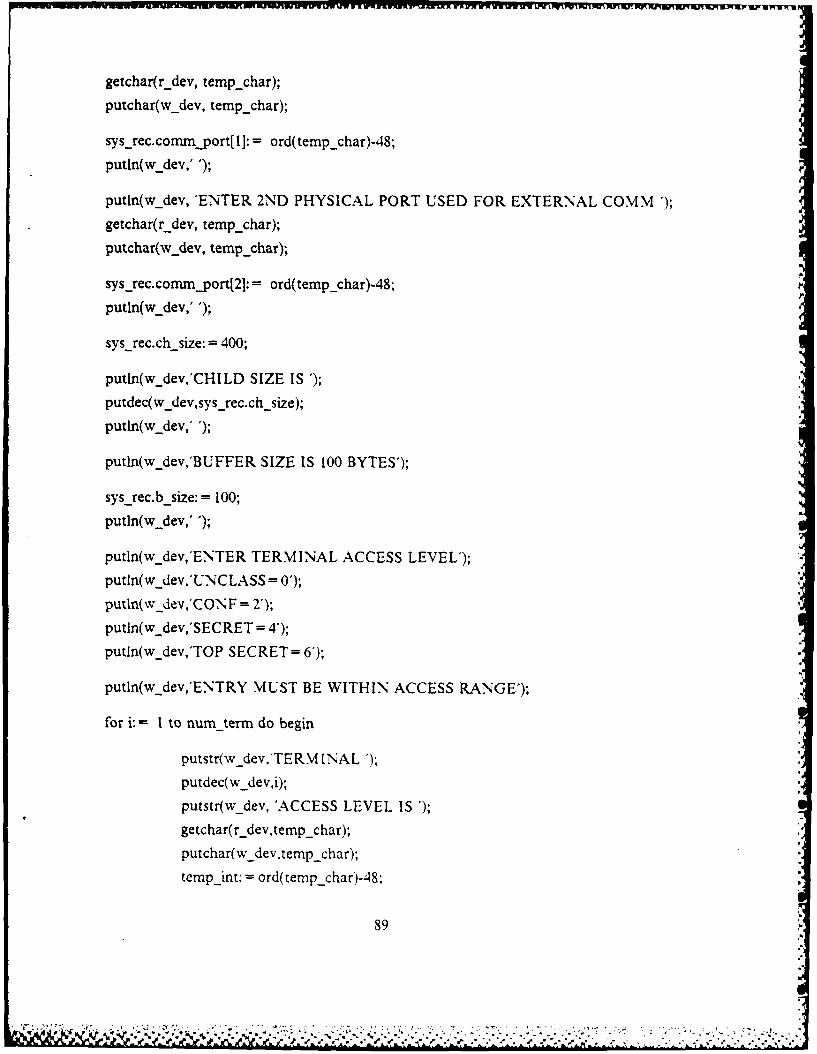
gechrrdvt mfhar; w-iww xw av~www F 1IWMPRI uwnruw
putchar(w dev, temp_char);
sys-rec.commjport[IJ: = ord(temp~char)-48;
putln(wdev,' )
putln(W_dev, 'ENTER 2ND PHYSICAL PORT USED FOR EXTERNAL COMM ');
getchar(rdev, temp_char);
putchar(wdev, temp_ char);
sys-rec.commjport21: = ord(tempchar)-48;
putln(w~dev,' ');
sys recxch size: =400;
putln(w_dev,'CI-ILD SIZE IS ');
putdec(wdev,sys -rec.chsize);
putln(wdev, ');
putin(wdev,'BUFFER SIZE IS 100 BYTES');
sys_rec.b-size:= 100;
putln(w dev,' )
putln(wdev,'ENITER TERMINAL ACCESS LEVEL');
putln(w dev,'UNC LASS = 0');
putin~wdev,'C 0N F = 2');
putln(wdev,'SECRET = 4');
putln(wdev,'TOP SECRET= 6');
putln(Wdev,'ENTRY MUST BE WITHIN ACCESS RANGE');
for i: I to num-term do begin
putstr(w_dev.'TE RMINA L')
putdec(W_dev,i);
putstr(wdev, 'ACCESS LEVEL IS )
getchar(r dev,temp char);
putchar(w dev,temp char);,
temp int: ord( temp char)-8
89

tempjint =temp mnt & S0007;
sysjrec.chaccessi] := class;
sys-rec.ch-access[iI.compromise[OI=
class. compronise[O1 & Sfflh;
sysrec.chaccess(i.compromise[O] =
sysrec.chaccessi. compromise[OI !temp i;putln(wdev,' ;
end; (for)
putln(wdev,'ENTER 8 CHARACTER INITIAL CRYPTO KEY (NO ECHO)');
for i: = I to 8 do begin
getchar(r dev,temp char);
sys-rec.key[i]: = ord( temp char);
end; (for)
putln(wdev,'CRYPTO KEY INSERTED');
{ fixed parameters '}
(code segment entry numbers}
* sys-rec.chld_ent[1]: =2;
svs-rec.chld_ent[2J1: =3-
putln(w_dev,'ENTRY OF PARAMETERS IS COMPLETE');
end; Iinput paraml
1rocedure: sys-config
Purpose: This procedure configures the external
communication ports identified in parm input for port to
port communications with flow control. They are attached
to read and write sequentially 8 bytes at a time to be
compatible with the data encryption device.
90
A~~~~~~~~~A~~~ -1 N I *''j%.* . **-% ~ ~ * ~ ~ AW * A ,

procedure sys config( sendjport: integer;
recvport: integer;
var config_suc:boolean);
var
rd-dev,wr-dev: dev name;
rdjpann,wrjarm:- devjparm-rec;
success: integer;
begin {sys config}
config-suc: = false;
putln(wdev,'CONFIGURING TRANSMIT AND RECEIVE PORTS');
{attach xmit and recv ports for computer to computer communications
{ fill-in attach-device calling arguments )
*** receiver should be attacheG first }
rd-dev.name: =sior;
rd-dev.num: =recv-port;
rd dev.d type: = o
device mode entries)
rdjparm.sior.mrl: = 504d;
rdjparm.sior.mir2: = S03e;
rdjparm.sior.io mode: = rts oflow;
rd_parm.sior.max: = 8;
rd_parm.sior.delim-active: = flalse;
attach-device( rd-dev,recv-st,rdparmsuccess);
show-err(' RECEIVER ATTACH ERROR',success);
Sattach transmitter }
91

wr-dev. name: - siow;
wr-dev.num: -send-Port;
wr-dev.d type: - io;
(device mode entries}
wrparm-siow-nmrl: = S04d;
wrjparm.siow.mr2: = 503e;
wrJparm. siow.io mode: = asrt-none;
attach-device(wr _dev,xritslt,wrjarm,success);
show err('TRANSM ITTER ATTACH ERROR',success);
putln(wdev,'COM MUN [CATION DEVICES ATTACHED');
I * xrnit and recv attached computer to computer no flow control }
config-suc: - true;
end-, (sysconfig)
Procedure: comm-tst
Purpose: This procedure checks communications in
both directions by transmitting a test string of data. Once
communications have been checked the comm devices are
detached.
procedure comm tst(init: r1..process defP
send port: integer;
recvport: integer;
var commn-tst-suc: boolean);
var
charin,charout: array [1..8] of char;
wr_class rd class: access_class;
92

arifarrawilwujW~r1FWvW1N WFW=WWrWW WW~W ~ vummmlvv Vj %. wl WvWWN W- wrvWwv'lWwmrd vv-vUwWum w
i,success: integer;
size: integer;
begin ( com tst )
comm _tst-suc: - false;
putln(wdev,'BEGINNING COMMUNICATION TEST');
{ ** transmidtter access-class for commn test ***
wr-class.compromise: =init.resources.max -class.compromise;
wr-class. integrity: = init. reso urces.nin-cla ss. integrity;
putstr(wdev,'TEST MESSAGE IS')
for i: = I to 8 do begin
charouttl: = 'T';
putchar(w-devcharouti);
end; (for)
putln(wdev,' )
write sequential( xmit slt,addr( charout,8.wr class.success);
show err( 'WRITE SEQENTIAL ERROR' ,success);
read sequential( recv slt,addr( charin),size,wrT class.success);
shjw-err('READ SEQUENTIAL ERROR',success);
for i: = I to 8 do
putchar(wdevcharinfi]).
putln(w..dev.' ');
detach-device(xmidtslt.success);
show err('TRANSM [ITTER DETACH ERROR',success);
detach-device(recv_slt.success);
show err('RECEIVER DETACH ERROR',success);
93
putln(wdev,'COMMUNICATION TEST COMPLETE');
comm tstsuc: = true;
end; { comm tst }
Procedure: att_crypto
Purpose: This procedure uses four process local
device slots to attach the required encryption and
decryption devices. Crypto key and feedback key are pro-
vided in the procedure call. Devices are attached using
the cipher block chaining (CBC) mode.
procedure attcrypto(crv_key: buf B;
cry fbkey: bufr;var att_cryptosuc: boolean);
var
rendev.wendev.rdedev,wdedev: dev name:
ren_parm.wenparm,wde_parm.rde_parm: devparmrec:
success: integer,
begin att_crypto }
att-crypto suc: false;
{ attach read encryption device ***
rendev.name: = dcpren;
rendev.num: = 0:
rendev.d_type: = io:
ren parm.ren.blk size: 8: S bytes per blk
94
9'4 '5-

attach-device( rendev~ren_slt,renjparm, success);
show err('ATTACH READ ENCRYPTION DEVICE ERROR',success);
( ** attach write encryption device 4
wendev.name: = dcpwen;
wendev.num: = 0;
wendev.d-type: = io;
wenjparm.wen.mode: =1; 1 for CBC mode)I
wenjparm.wen.key: = cry key;
wen parm.wen.fb key: = cry fbkey;
attach deiewne~e~l~e~am ucs)
show err('ATTACH WRITE ENCRYPTION DEVICE ERROR',success);
{ ~attach read decryption device *4
rdedev. name: = dcprde;
rdedev.num: = 1;
rdedev.d type: = io;
rdeparm.rde.mode:= I;( for CBC mode4
rde-parm.rde.key: = cry key;,
rdeparm.rde.fbkey: =cry Lbkey;
rdeparm.rde.blk-size: = 8;
attach device(rdedev,rde_slt,rde_parm,success);
show err('ATTACH READ DECRYPTION DEVICE ERROR',success);
{ attach write decryption device 4
wdedev.name: =dcpwdle;
wdedev.num: =1;
wdedev.d-type: = io;
(wde-parm is blank record4
attach-device(wdedev,wvdest,wde_parmsuccess),
show err('ATTACH WRITE DECRYPTION DEVICE ERROR,'siucce&-1
95
50-___ -

AO-A±693 361 A DEMONSTRAITION OF A1 TRUSTED COMPUTER INTERFACE SETNEEN 2/'2MULTILEVEL SECU..(U) NAVAL POSTGRADUATE SCHOOL
MIFI MONTEREY CA G E RECTOR MAR 87F/255H
Emmohhmhhoml
mmhhhhhhhmmslEhhhmmhmhlo

41111 " 3 ,2
I-,. L'.2
W V iw .~w .. w -.. Iw .-.w w *w w .

att crypto-suc: - true;
end; { attcrypto }
Procedure: crypto-tst
Purpose: This procedure verifies that the
encryption and decryption devices are working properly.A test string is encrypted then decrypted using testkeys. Results are output to the tims terminal. When
complete all data ciphering devices are detached.
procedure crypto tst(init: rl process def;
crypto tst-suc: boolean);
var
encryptin,encryptout,decryptout: array [1..8] of char;wrclass,rdclass: access-class;
size: integer;
i: integer;
success: integer;
procsuc: boolean;
begin { cryptotst }
crypto_tst_suc: - false:
putln(wdev,'BEGIN ENCRYPTION DEVICE TEST');
wr class.compromise: = init.resources.max class.compromise;
wr class.integrity: = init.resources.minclass.integrity;
putstr(wdev,'ENCRYPTION TEST STRING IS );
96
":. ' ' l" ,," ' ,,g ; : ' ',' " " .:,.' ' . , ' ', ': ' '. ,i' ,- .-. -- '- , i, " ;' .",,', t, ,. :, ,,-.."... ,,'. .'. . .. ,.. .... ,

for i: -I to 8 do begin
encryptini]: -''
putchar(Wdev,encryptin[il);
end; (for)
putln(w _dev,' )
( **write test string to encryption device I
write-sequential(wenslt,addr(encryptin),8,wr-class,success);
show err( WRITE ENCRYPTION SIOW ERROR,success);
( ** read encrypted string ** )
read sequential(ren slt,addr(encrypotsz dclssccs)
show err('READ ENCRYPTION SIOR ERROR',success);
putst(Wdev,'ENCRYPTED STRING IS');
for i:' -Ito 8do
if (ord(encryptout[iJ) > - 40) and
(ord(encryptoutlil) < - 176) then
putchar( w dev,encryptoutl ij);
putln(wdev,-);
write encrypted string to decryption device
write sequential( wde slt.addr( encryptouc).8 .wr class.success).
show err( 'WRITE DECRYPTION SlOW ERROR',success);
1*** read decrypted striig -*
readsequential( rde slt.addr( decryptout ). size .rd class, success)i;
show ..rr('READ DECRY'PTION SlOW ERROR,success).
putstr(w-dev.'DECRYPTED STRING IS
for i: -1 to 8do

putchar(wdev,decryptouti]);
putln(w dev,' ");putln(w. dev,'ENCRYPTION TEST COMPLETE');
( *** detach encryption/decryption devices * }detcrypto(proc-suc);
crypto-tst-suc: - true;
end; { cryptotst }
Procedure: termjproc create
Purpose: This procedure creates a single level
child process for an untrusted tds using the parameters
specified by the system manager. The child process
code segment is a single level utiity program which attaches
the child process at the desired physical port. Four seg-
ments are passed to the child process. The stack segment
contains the ch init:rlprocessdef record. The two
common message buffer segments (inbuf and outbuf) are usedto pass messages between the parent and child processes.
Finally a code segment is required for all child processes.
Process local segment numbers as well as pointers to the
message buffer segments are passed back to the main pro-
cedure when the child process has been created.
procedure term_proccreate( mit: r Iprocess de,
chparm: sysmgr recchld num: integer.
%ar stk %lot:.h _,rra'-
var outhuf_slot: ..h_arras;

var inbuf slot: ch-array;
var outptr: pointer;
var inptr: pointer;
term create suc: boolean);
var
DEBUGI: INTEGER;
DEBUG2: INTEGER;
ch-cde-segnum ch-array;
chld-entry: integer,
ch-init: r l.processder,
ch-addrjec: r laddr-array;
ch-reg~ec: r I regrecord;
ch-res-rec: ritres record;
ch-segjist. seg array,
stkinitjptr: rlj rocess def-
stkjpcr: varpointer;
inbuf ptr,outbuf tr. array (I ..num zerml of pointer;
seg~rgr by-tes: integer;
stack size,chld size,buf size: integer;
stk-evcyval: ch-array;
size.success: integer;
i.j: integer;
class: access clas s;
begin (termproc create}
term-create-suc: - false;
Sinitialize child parameters
chld size: -c hparn.ch size;
buf-size: - chjparm.b size;.
j- chid-num.
chid entry: chparm. chid entljlI-
99

create, makeknown, and swapin child segments
{ rakeknown terminal utility code segment located at child
entry number specified in sysmgr.ssb file )
segmakeknown(init.initial -seg[rootoffsetl,chld-entry,
ch-cdesegnul,re,sizeclass,success);
show _err( MAKE KNOW N CHILD ENTRY E RROR',success);
( Determine required size for stack. It must be large
enough required information for child initialization.)
segmgrbytes: - sizeoifstack header) +sizeofqkstheader)
+ (sizeofi kstentry)init. num-kst);
stack-size: - r I stack-size + vect size + seg mgr bytes - 1;
I * create, makeknown, and swapin child stack segment }
seg..create(ch -cde -segnu j,O,stack-size,success);
show err('CREATE CHILD STACK ERROR',success);
segmakeknown( chcdeseg nurjOstslot[jJ,r wsize,
class.success:.
show err('MAKEKNOWN CHILD STACK ERRQR',success);
swapinsegment( rk~slotljI ,success)-.
show err( SWAPIN CHILD STACK ERROR',success);
( stack eventcount is used to notify sys migr that the
terminal process is activated. It is also used as an
entry in the ch-init record
read evc( stk slot~jj~stk evc val~jj,success ):
show-err('READ STACK EVC ERROR'.success).
stk-evc-valbJ stk evc valijJ + 1;
c reate mesage huffers
I 00

{outgoing message buffer}
segcreate(ch cde seg urrj],I ,buf size,success);
show _err('CREATE OUTBUF ERROR',success);
segmakeknown(ch-cdeseg._numfj], I,outbuf slotUjJ,
r -w,size,class,success);
show err( MAKEKNOWN OUTBUF ERROR',success);
swapinsegment(outbuf slotj],success);
show err('SWAPIN OUTBUF ERROR',success);
( incomi ng message buffer}
segcreate(ch -cde segnunJ],2,bufsize,success);
show err(CREATE INBUF ERROR',success);
segmakeknown(ch-cde-segnuj,2,inbuf slofjJ,
r -w,size,class~success);
show err('MAKEKNOWN INBUF ERROR',success);
swapinsegment(inbuf slotjj,success);
show _err('SWAPIN INBUF ERRORW,success);
{ ** fill in chseg~jist ** )
{ch seg list determines order in which segments are passed
to the child process )
chsegist(stack_offsetJ: - stkslotj];
chseglistcodeoffsetj: - chcdescgnumljJ;
chseglistrootoffsetj: - init.initialsegfrootoffset];
ch~seglist(outbuf-offset]: - outbuf slotljl;
chseglist inbuf offset]: - inbuf sloijj;
(**fill in child init record }
ch mnit record is placed on stack for use by child
process when created
chilnit.cpu: -init-cpu;
11

ch-int.num kst: - init.num-kst;
chmiit.root access: - init.root access;
chjinit.s-seg: - stack-offset;
ch-iit.sjegevent: - stk-evc-valol- 1;
chnt.resources. priorty: - init. resources. priority- 10;
libjinteger..to b24(chld size,ch init.resources.memory);
chjnit.resources.processes: - 2;
chjinit.resources. segments: - 90;
{ min class and nmax-class determine the access level of
the child process. Since the terminal process is single
level, they are the same. Levels are specified by the
sysmgr during the parmjinput initialization. )
ch-init.resources.min-class: -chjparm.ch -accessol;
ch-init.resources.max-class: -ch..parmch-accessol;
chjinitsp2: - 0;
ch-iit.ring-num: 1;
( ** create stack pointer }
(stack pointer is offset to start of rljrocess def
stkjnr.seg: - lib-mksel( ldt table,stk-slotUl, 1);
stk~ptr.offl- stack- size-( vect size +seg mgr bytes
-4-sizeof~rljprocess def)) + 1;
stkjinitptr: - stk~ptr.p;
( copy ch mnit on to stack
move(chinit.stkinityPtr .sizcoq~rl process def));
(create pointers to message buffers}
point to start of message buffer, no offset}
outbuf ptrfjl: - lib mk_pntr(Idt-table~outbuf slot[j],1);
inbuf pttj]: - librnkpntr( Idt table,inbuf slot[], 1);
102

{ fdin remaining records for createprocess call }
( child address record}
{ a maximum of 5 segments may be passed in ch addr array }for i:= 0 to 4 do begin
ch.addrjrec[i].segment number: - ch-seg.listi];
{ code segment must be of type read execute }{ others are type read-write }
if i - I then begin
ch-addr-rec[i].segmenttype:- r-e;
end else begin
ch.addr.reci].segmenttype: = r-w;
end; (if)
( swapin allsegments except rootoffset }
if i - 2 then begin
ch-addr-recli.swapin: - false;
end else begin
ch addrjrec[i].swapin: - true;
end; (if)
ch-addr-rec[i].protection: - 1;
end; (for)
*** child register record ** }
chregrec.ip: = 580;
chregrec.sp: - stk_ptr.off,chregrec.sp 1: - stacksize-(vectsize + segmgr bytes) + 1;
chregrec.sp2: = 0;
ch-regrec.vec-seg: = 0;
103

chregrec.vec-offi stack-size-vect size + 1;
*** child resource record }
{child I is located at ch -res -rec.chld-num- 0
ch-res-rec.child-numn - chid-num-I;
ch-res-rec.priorty: = ch-init.resources. priority;
ch-res-rec.memory: = ch-init.resources. memory;
ch-resjec.processes: - Jh-nit.resources.processes;
chjesjec. segments: - ch-init. resources. segments;
ch-res-rec.miin-class: =chparmnch-access[chld.num];
ch-res rec.max-class: =chjparm.ch-access[chld-num;
injptr - inbuf ptrj];
outptr: = outbuf ptrU];
putln(wjdev,'CREATING CHILD PROCESS');
createprocess(chaddr -rec,ch -reg-rec,ch-resrec,success);
show err('CREATE CHILD PROCESS ERROR',success);
{wait for child process to advance stack eventcount
indicating that child process is active}
read-evc(stkslotj],DEBUG 1,success);
read-evc(chCdesegnuljj,DEBUG2,success);
putstr(wdev, 'AWAITING STACK VALUE ');
putdec(w_dev,stk-evc-valUj);
putstr(w _dev, 'CURRENT STACK VALUE ');
putdec(wdev,DEBUG 1); USED FOR DEBUGGING
putln(w._dcv,");
putstr(w ~dcv, 'CURRENT CODE VALUE ');
putdec(wdev,DEBUG2);
putln(wdev,");
await( stkslotU ],stkevcvalUl, success);
show err( 'AWAIT STAC K ADVANCE E RROR',success);,
readevc(chcde-segnunfjJ,DEBUG I .success);
104

putln(w_dev,'CODE VALUE AFTER AWAIT ');putdec(wdev,DEBUGI);
putln(w dev,");
DEBUGI := outbuf ptrj]
show err('CHILD ATTACH FAILED ', DEBUGI);
putln(wdev,'CHILD PROCESS CREATED');
termcreatesuc: - true;
end; { term_proccreate }
Procedure: xmit rec
Purpose: This procedure takes the message stored
in the outgoing buffer of the source terminal, encrypts
each block, and transmits it sequentially via the
appropriate external communications port. The crypto-
graphic is provided by the sysmgrrec. The fb key is
initially input by the system manager. (Then the encrypted
block becomes the fb_key for the next block.) At the receiver
the message is decrypted and stored in the incoming message
buffer of the destination terminal. Access levels of the
msg and dest are compared. If they do not match the msg
is not delivered, and an error msg is returned to the
source.
procedure xmit recv( ch_parm: sysmgrrec;
origterm: integer;
dest term: integer;
o_out ptr: pointer;
o-inptr:pointer;
105

d-outptr: pointer;
d-in~ptr: pointer;
var int-mess-nuntinteger;
var recv-suc: boolean);
var
out rec~in rec: buf rec;
iAjptr,outjptr. array [1 ..num term] of pointer;
time: cc-array;
fbkey. bufB,
srce,dest: char,
int-dest: integer;
str-mess_num:string;
encryptout,decryptin,decryptout: array [1..8] of char;
ij: integer;
size: integer;
recv-class,xmit -class,class: access-class;
count: integer;
success: integer;
dest-comp,mess-comp: integer;
proc-suc: boolean;
temp char: char;
begin (xmit recv}
recv-suc: - false;
putln(wdev,'ENTERING TRANS MIT/ RECEIVE MODULE');
sysconfig(orig_term.dest-term,proc-suc);
{ ** retrieve message stored in originator's outgoing msg buf "~
move( ooutjptr ,outrec, size off out-rec));
( fill in remaining address block entries }
(outgoing message number
106

out-rec.num: - int mess-num;
{message classification)
out rec.block[ 11161: = chr(chjparm.ch accesslorig term].
compromise[O] + 48);
{insert message number in address block}
binascii(int mess nurm,4,str mess num,'0');
for i:= -Ito 3doout-rec.block[I i + 21: = str-mess numi;
increment message number counter}
int mess-num: = int-mess num + 1;
putln(Wdev, 'ENTER THE 8 CHARACTER ENCRYPTION KEY.');
for i: = I to 8 do begin
getchar(r dev,temp char);
fbkey[i]: = ord(tempchar)-48;
end; (for)
putin(wdev,'ENCRYPTION KEY INSERTED');
( transmitter access class}
xrnit class: = ch-parm.ch-accessiorig term];
begin transmitf receive loop
for i: = 1 to out rec-num-bik do begin
{in cbc mode crypto devices must be reattached to transmidt
107j

Ixan W ... 1 U, F w kPW. -.rwwsWL~ nn
each block, this is required because the previous encrypt-
ed block is used as the fb key to encrypt the next block.)
att-Crypto(chjarm.key,fbkey,proc-suc);
t write to encryption device}
wirite sequential(wen-slt,addr( out -rec.blockfiJ),8,xmit-class,success);
show _err('WRITE ENCRYPTION SIOW ERROR',success);
{ read encrypted text )
read sequential(ren slt,addr( encryptout),size,class,success);
show err('READ ENCRYPTION SIOR ERROR',success);
( transmit encrypted block }
write sequential(xznit slt,addr( encryptout),8,xmitclass,success);
show err('TRANSMIT ERROR',success);
( determine fb key for next block)
for j: = Ito 8do
fbkeyfl: = encryptouto];
begin receiving message
{receiver access class}
recv-class: = chjparm.ch-access[dest-termj;
(read encrypted text}
read sequential(recv slt,addr(decryptin),size,class,success);
show err( 'RECE IVE ERRORW,success);
putln(w; dev, RECEIVED MESSAGE IS');
for j:= Ito 8do
108
.. . -- ,' . . . . . . *---'A,
X4 ,. * S)~ 'S~- '

putchar(w._.dev,decryptinbj);
putln(wdev,' ');
[(write to decryption device}
write sequential(wde slt,addr(decryptin),8 ,recv -class,success);
show err('WRITE DECRYPTION SIOW ERROR' ,success);
{ read decrypted text }
read-Sequential(rdeslt,ad dr(decryptout),size,class,success);
show errC'READ DECRYPTION SIOR ERROR',success);
putln(wx_dev,'DECRYPTED MESSAGE 1S');
for j: = I to 8do begin
in-rec-blockIli1b: - decryptoutlil;
if (ord(decryptoutUjj) > - 40) and
(ord(decryptoutU]) < = 176) then
putchar(wdev,decryptoutU 1);
end;
putln(W dcv,'')
{count is number of blocks in received message}
count: = count + 1;
( detach crypto devices to prepare for next block)
detcrypto(procsuc);
end; (for)
detach(xnuctslt);
detach(recv sit);
109

message transmitted and received
{insert number of blocks into incomdig record}
mnrec.num-blk: - count;
{ decode address block}
srce: - in -rec.block[J[1];
dest: - in -rec. block[1][2];
putstr(w-dev,'DESTINATION IS');
putchar(wdev,dest);
int-dest: - ord(dest)-48;
putstr(wfidev,'I NTD EST IS');
putdec(Wdev,int -dest);
putln(w dev,' ');
dest-comp: - chjparmch-access(intdest]compromise[O];
mess-comp: = ord(in - ec. block[ 1][6])-48;
putln(wdev,' ');
putstr(wjiev,'DEST-COM P.M ESS-COM P');
putde(Wdev,destcomp);
putdec(w dev,messcomp);
putln(W_dcv,' ');
{compare message and destination access levels for
possible security violation}
if mess-comp < > destcomp then begin
{if srce - '0' then incomning message is an error
message concerning a security violation4
if srce < > '0' then begin
putln(w._dev,'SECURITY VIOLATION MESSAGE 'NU MBER');
for i. 3 to 5do
110

putchar(wdevinec. blocki I IiJ);
recvsuc: - false;
( prepare error msg for transmission I
errjnsg( srce,dout_ptrproc suc?;
end else begin
( if incoming traffic is an error msg then
move it to the incomming message buffer of
the destination terminal
move( in_rec,din.ptr ,sizeoqin-rec));
{ reset recvsuc )
recvsuc: M true;
end;
end else begin
(if no violation, move msg into incoming rsg
buffer of destination terminal)
move(in-rec,d-in-ptr ,sizeot~inrec));
recv suc: = true;
end: (ifl
end; { xmztrec)
Procedure: errmsg
Purpose: In the event of a secunt. violation.
this procedure fills destination outgoing buffer with
an error message. This error message is then transnutted
to the source for display at the onginator s ternunal.
III
'%'VVV ' 1 Vw<. -.
' [ r - ' '
l" " ;i' :- " - "
.a.. . . . . . .1 'Wo

procedure err nsl dest:char,
xnutptr:pointer:
var err msLsuc:boolean);
wa~r
err rec: bufrec;
iinteger.
be (errmsg
errec.num - 0.
Serror msg has only an address block
err rec.nwn bik:-!I
source of 0 indicates an error message
errrec, block( I I 1:- '0;
err rec. block 1121: - dest;
: remainder of address block is empty
for1:- 3toSdo
err rec.blockltll]:" 0.
move error message to outgoing buffer of Jest term
for transrmssion back to source
movet err_rec.xmntPtr .sizeollerrrec i ;
end;, err msS;
Pro4.edure Jet cr' pto
%2

Purpose: This procedure detachs all data
encryption: decryption devices.
procedure detcrypto(var procsuc:boolean);
begin (det_crypto)
detach(wensit);
detach(ren_sit);
detach(wde-sit);
detach(rde_slt);
end; (detcrypto)
Procedure: show err
Purpose: This procedure is called to display
the success code of the resource management call if it is
other than zero. If the success code indicates no error
then no message is output.
*ee. S '@0di e.a.....0 sO Q*8 ,ms' e * s seiasd * . s iee*dB. . i . . e .e e s ee .s
procedure show_err(str: string;
code: integer);
begin show_err)
it'code < noerror then begin
putstrnw_dcv.str ;
putstr(w-dev. *);
putdeco w de.%' ode ).
putlntw_Je'.
113

end-,
end; ( show err )
Procedure: main
Purpose: This procedure initializes system
operation. It performs comm and crypto checks and then
creates a single level process for the remote terminal.
Once the system is on-line, it controls access to the
external communications ports. Messages are transmitted
and received, and security checks are performed on all
incoming traffic.
procedure main( var init : rlprocess-deo;
var
DEBUG: INTEGER; 000 USED FOR DEBUGGING *
i: integer,
stk slt.bufoutslt,buftinslt: ch arrav;
bufout_ptr.buftinptr: array Il..numterml
of pointer;
bufout evc,bufin-evc: ch-array;
mgrrec: sysmgrrec;
testkey.test_fbkev: bu(S:
mess-dest.mess srce: integer;tempt _port.temp2_port: integer;
success: integer;
ch num: integer;
proc suc: boolean;
recv suc: boolean;
I1 1
* - % ~ *%*,. ~ ~ * % * * . -

niess num:in teger.temp-class : access-class;
begin (main)
if (init.cpu < > 0) then begin
self delete(init.initiailsegjstackoffsetj, success);
await( init.initaal seg[stack offsetl, 32000, success);
end; (if)
attach(0,w-dev,false,success).
if (success < > no-error) then begin
self delete( init.initial segistack offsetj, success);
await( init-initial segistack offset], 32000, success);
end. ( if)
attach(0,rdev,true,success,;
if (success < > no-error) then begin
show err(*ATTACI- R-DEV FAILED ', success);
self delete( inut.initial segfscackoffsetj, success);
await(init. initial segfstack_offsetl, 32000. success!i;
end,- ;fi
putin(w-dev,'SYSTENM MANAGER TERMIINAL ATTACHED');
call procedure to enter system parameters
temp class-cornpromrise : - nit .resources.max -class. compromi se;
temp class. integrity :- init, resources. mm _-class, integrity',
input parami temp class.mgr rec.proc_ ,uc i
xmriit recv ports for conim tst
templpot: - mgrrec-commpot -1
temp2_port: - mgrrec.cornrnportj2l.
configure xnuc recv ports
sysconfig( temp ljpon,temp2_port,proc-suc);
( test comm channel pass I1
comm -tst( init,temp I _.port,temp2 Jport,proc sue);
( reconfigure xm-ic,'recv ports to transmit in opposite dir}
sys~config( temp2_port,templ1port,procsuc);
{test comm channel pass 2}
commntst(init,temp2_port,temp I _port,proc_suc);
(attach crypto devices in CBC mode}
attcrypto( mgrrec.key,mgrjrec.key,procsuc);
{ test crypto devices
cryptotst( init.procsuc:.
putln(wdev,'SYSTEM INITIALIZATION COMPLETE');
{loop to create child process for each remote terminal}
for i: I to num term do begin
ch num: i.
create child process
terrnproccreate( Int,
mgrjrec,
ch_num,
stk-sit.bufout-sit,
buln-sit.
bufout_ptrfiil,bufinptr ii.,
116

putstr(w dev,'CHILD PROCESS CREATED TERMINAL ');
putdec(w _devjz);
putln(wev,' ');
{ initialize buffer event counts }
bufmnevcli]:= 0;
bufout evc[i]: - 0;
end; (for}
{Initial message destination is terminal 2.}
mess dest: - 2;
mess num: 0;
{ To start systam advance inbuf evc for terminal 1.}
advance(bufmslt[ 1], success);
show err('START SYSTEM INBUFFER ADVANCE ERROR', success);
hhPP { initialize message receipt success value)
recv-suc: - true;
begin independent system operation loop
while true do begin
(inner loop synchronizes terminal to terminal communications }
for i I I to num term do begin
mess srce: i:
mess num: - mess num + 1;
( check for received message security violation )
if recv suc - true then begin
{ if no error then wait for next outgoing message
117
..
I#I
I'S
' , .. ,,,' :-, -,,sa.ir,.1; ,.'s .:: ?: .- -;o:, .., **n*. j ) .. W, x:,.:,--.:: ,.-. <..-

bufout-evc[i] -bufout evc[i] + 1;
USED FOR DEBUGGING
read evc(bufout Slt~il,DEBUG,success);
putstr(wdev, 'IN LOOP AWAITING VALUE ');
putdec(wdjev,bufbut -evc[ij);
putstr(wdev, 'CURRENT VALUE ');
putdec(wdev,DEBUG);
putln(wdev,-);
await( bufoutslt[i,bufout evc~i, success);
show err('AWAIT MESSAGE READY FOR TRANSMIT',success);
putln(wdev,' MESSAGE READY FOR TRANSMISSION');
{ transmit and receive outgoing message)
xmt-recv(mgrrec,mess-srce,mess-dest,
bufout~ptrdmess_srce,bufinjptrjmesssrce],
bufoutptrf mess dest],bufinjptrt mess dest],
mess num,recv suc);
putln(wdev,'MESSAGE SENT');
( notify message source that message was xmnit}
advance( burm nslt[messsrce,success);
show err('ADVANCE SOURCE INBUF ERROR',success);
(check for received message security violation4
if recv-suc - true then begin
{if no error then notify dest terminal
to display incoming message
advance( bufinslt[messdest], success):
118

show err('ADVANCE DEST INBUF ERROR',success);
putln(wdev,'MSG RECVD AND DELIVERED');
{ new dest term is message srce )
messdest: = i;
end else begin
( if security violation did occur then
transmit error msg back to source. error
msg has already been placed in outgoing
buffer by procedure xmit.recv. }
xmit recv( mgrrec,messdest,mess srce,
bufoutptrlmess dest],bufinjptr[mess-dest],
bufout_ptr[mess-srce,bum_ptr[mess_srcel,
mess num,procsuc);
putln(wdev,'ERROR MSG TRANSMITTED');
( notify source of incoming error message )
advance(bufin-sit[mess-srce,success);
show-err('NOTIFY SRCE OF ERROR ADVANCE',success);
end; (if)
end else begin
{ if received message had a security violation theloop will return control to the message source sothat he can display the error message I
{ recvsuc = true to allow display of error msg }
recv-suc: true;
end; (ifn
end; (for)
119
.q7.

end; (while)
putln(wdjev,'PROGRAM COMPLETE');
while true do;
end; (main)
modend.
120
X1 ~

I ~ ~ ~ ~ ~ ~ w MunFnn0RfMMRolM
APPENDIX EGUARD.KMD LINKING FILE
Program: GUARD.KMD
Date: 7 February 1987
Author: G. E. RECTOR, JR., CAPT/USMC
Advisor: T. J. BROWN, MMJ,USAF
Purpose: This program is used when linking GUARD.It eliminates the need to manually enter each of the filenlames each time a new version or update of the programis compiled.
guard =rimit, guard, rllib/s, paslib/s,p:80
121

APPENDIX F
GUARD-CON.ZLI INCLUDE FILE OF CONSTANT DECLARATIONS
Program: GUARD-CON.ZLI
Date: 7 FEBRUARY 1987
Author: G. E. RECTOR, JR., CAPT/USMC
Advisor: T. J. BROWN MAJ,'USAF
Purpose: This file is developed as an include file andcontains constant declarations used for the multilevel inter-face application program. This file must be included in theconstant declarations for each module.
num term =mess-bufsize ' 4;
xmit sit = 6;recv-slt 7;
wen sit - 2;ren sit =3wd€ sit -- 4,rde -lt - 5;
stack offset = 0;code -offset = 1;root offset - 2;pb oset 3;outbuf offset = 3;inbufUffset = 4;
********************** end of guard-con.zli *
122

WW WMV~rW~1W1W~rWM qwqw~ww- W Wx ... W- FIC
APPENDIX GGUARD-TYP.ZLI TYPE DECLARATION INCLUDE FILE
Program: GUARD-TYP.ZLI
Date: 7 FEBRUARY 1987
Author: G. E. RECTOR, JR, CAPTUSMC
Advisor: T. J. BROWN, MAJ/USAF
Purpose: This file was developed as an include file oftype declarations to be used with each module of this application.
sysmgrrec = record
commport : array [1-.2] of integer;b size : integer;cli size : Integer;ch-access :array [1 .num term] of access class;chrd ent arrayf I .num fermi of integer;-
end; key --buf8;
buf rec =record
num : integer;num blk: integer;blocZ: array [i..mess_buf size] of array [L..8] of char;
end;
ch-array =array [1. .num term] of integer;
~~~~ ~end guard-typ.zli ~***********
123

APPENDIX HTDS1 TERMINAL UTILITY PROGRAM LISTING (JANUS ADA)
The TDSI terminal utility package is compiled and prepared for execution in
almost the same manner as the system manager module. By modifying certain
parameters which are identified in the program listing, the system manager may specify
the specific port and terminal number of each remote terminal process. TDS.CMD
files are created for each terminal attached and are essentially identical except that
TDSI is written in Janus ADA and TDS2 is written in PASCAL MT+. Each is
compiled, linked, and sysgened separately, but perform identically. A TDS.CMD file
is submitted with the GUARD.SSB file for each remote terminal attached. To attach
additional terminals. (as more ports become available), entry numbers would have to
be specified in the GUARD.SSB file. Janus ADA is compiled and linked in a manner
very similar to PASCAL MT+. A library file was created providing the ring 0 and
ring 1 calls similar to those developed by Gemini for PASCAL MT+. A listing of the
library file DEFS.lib and the package body DEFS.PKG to support that librar" are
listed as Appendices I and J.
124
.. -\ * .. . " " . ." .. . .r . -,* . . ...

WITH agate. agatei, art. alib. alibi, strib. util. defs:
PACKAGE BODY TDSI IS
USE agate, agatei, art. alib, alibi, strhb, util, dels;
Program TDSI
Date: 11 FEBRUARY 1987
-- Author G. E. RECTOR CAPT LSMC
-- Advisor: MAJ. T. J. BROWN MAJ USAF
-- Purpose: This program is initiated when the system
-- manager creates the single level TDS process. It allows
-- the TDS operator to enter and send messages via the system
-- manager process, as well as display incoming messages.
-- Message specifications and terminal access level are deter-
-- mined by the system manager process and passed to the TDS
-- process in its rl.processdef record. Other system constants
-- are provided in the guard-typ.zli and guard-con.zli tiles.-- Incoming and outgoing buffers are used to store messages.
-- Eventcounts for these segments are used to synchronize system
communications.
-- Constants used by this program
t_phys_dev : CONSTANT Integer:= 100;pcdev : CONSTANT Integer:= 10l;
termnum : Constant Character - 'I;
-- Variables used by this program
125
.I-, -,"'.' " - . " " . .... ..C . . - -. " " - . ... . . .. '' ' ' '" 4 " ,' - ,. .- , " • -'-",,, ." - .. ,,". ' ",-",-" ". '. " . -" - -" - e" -" -" -".- .- .- . .. '.- . '."." . . '. .. ,- . .- - -. •.4

Debug: Integer;
Debugptr : Pointer:Success: Integer;
Seg_nux : Integer;
Mode Character;
Xrmtbuf statRecbufstat Boolean;
Temp str : String( 1);
i,Level : Integer;
inbufevc : Integer;
Stk-evc : Integer-Sys_start : Boolean.
Begin
-. initialize terminal process parameters
Xmit buf stat :- False;
Mode:- "0"
s/s start - f alse for twerminal I only all
-- other terminals should have sys_start - true
Sys start : - (Termnum - ');
Inbuf evc :.- 0: -- attach terminal as read. write device
Attach(T_phvs dev.W dev. False.Success i:
Ifl Success -No error) Then
Debug '- Success:
Swapin segmentf I nit. I nitial se( Outbuf offset .Success) ;
Debugptr • Libmk pnr Ldt tabie.Init. Initial segtOutbuf olfset).l )
Debugptr • - Debug;
End If;
Attach( T phys dev, R devTrue.Success);
Ifl Success - No error) Then
Show err"ATTACH R DEV FAILED ".Successi,;
End If-
Putln(W dev,.Putln(W dev."TERMINAL ACTI VE"):
Putchar Wdev.Termnnuni);
Putlnj W_dev..
126
re t.i %,.%%,...-,, ,G ,.,,,•.. ... ...... ,..,.... . .- /,: .- ,., .,. , .: , ., *

stack eventcount is advanced to notify
-- sysmgr that ternunal is activated
Advance( :it. Initial_seg( Code offset ,Success j;
Advance I nit. I nitialseg( Stack offset ). Success );
Showerr("STACK ADVANCE ERROR.Success;
-- loop until operator enters e to indicate logotT
While Mode - 'e- Loop
-- inbuf evc is used to have the terminal wait after
-- transmitting a message until a reply is received
-- from the dest term. It is initially advanced for
terminal I to start the system and then is advanced
-- upon receipt of an incoming message
lnbuf evc : - Inbuf evc - I;
Await( I rut. I nitial_seg( I nbuf offset ). I nbufevc, Success );
Show ern'AWAIT INCOMING MESSAGE-,Success);
-- s.s start is used to avoid the display incoming
-- message prompt at terunal I when the system is
started. Once the system is operating it will
always be true
If Sysstart Then
Rec buf stat : True;
PutlniW dev."DISPLAY INCOMING M ESSAGEi
End I :.
Sys_start : True:
-- inner loop is used to indicate that a
message has been sent and alert the operator
-- that the terminal is waiting for a reply
While (Mode - "X') Loop
-- help menu consists of a display of term
-- access level, and a display of" possible
modes
Putstr(Wdev."TERMINAL COMPROMISE LEVEL');
Level : lnit.Rootaccess.Compromruse( Ii;
Case Level Is
When 0 - >
127

PutlnW dev. -UNCLASS I F1 ED");When'. 2 >
Putrn(W-dev. CONF IDENTI[A Lp;
When 4 =->
Putln4 W-dev.-SECRET-).
When 6 = >
PuzlnWdev.'TOP SECRET-);
End Case;
Putln(Wdev.-ENTER MODE DESIRED");
Puti(W-dev.i-I INPUT MESSAGE');Putin(W-dev.-D DISPLAY RECEIVED MESSAGE-);Putin( WdevX -TRANSM IT M ESSAGE;Puln4 Wdev.'E LOGOFF-);Putrln&W dev. ');PutsrrnW dev.'EN\TER MODE HERE");
Getchart R dev. Mode);
I flMoe > 'a'iAnd'M od <- 'z'Then
Mode -Character VaR Type name Pos( Mode)
Typ namPos"a') + Tvp name'Pos(-A-);End If;If Mode - -I- Then
If Xrtbut'-stat - False Then
-enter message to be stored in-outgoing message buffer
I nput mess4 I rit. Resources. MIin-class.
[nit. Initial seg(Outbuf o(iset),Xmritbuf-stat);
ElsePutIn1W dev,-MvESSAGE WAITING TO BE TRANSMITTED-);
End If.
Elsif Miode D '1'thenIf Rec buf -stat - True Then
Putin(W dcv,' ENTERING DISPLAY MIODULE")displa%, contents of incoming
-. messaize buff'erDispmss I nit. Initial-seg( Inbuf' offset .Rec-buf-stat );
128

Else
PutlnWdev,IN'COMING BL FFER EMPTY-),
End If.
Elsif Mode - -X-Then
If Xmit buf stat - True Then
Put~nmW_dev.SENDI\G MESSAGE' ;
Xrnitnss4kmt. I nnaal_seg~ Inbuf offset),
lnit. I niial segOutbuf offset), Inbuf evc.Xrit buf stat ).
ElsePutnWdev,'OLTGOI\*G BU FFER E.MPTY?);
Mode: - "0.End If-,
Elsif Mode - "E ThenPutln(W-dev. LOGO FF PROCESS INITIATED* );
Else
Puttrn(W-dev.-MODE ENTRY ERROR. TRY:\G;Al\iN
End If, -- end of inner loop-exit after msg xnmt
End Loop;
Putl(W-dev.-WAITI\NG FOR INCOMING MESSAGE-);.reset mode selection value
Mode:- '0";
End Loop.
PutlnWdev.-END OF TDS TERMINAL PROCESS")Detach(W-dev i:
Detach(R-devi:. -- infinite loop to avoid crash
While True Loop
End Loop,
End TDSI-,
129
APPENDIX IDEFS.LIB LIBRARY DEFINITION FILE
Witamwbitek arl. abib. alibl, striib. util;
ISagate. agate), an.I abb ahibj. strhib. uti;nwn ter :COM NT N~ner: 2;
nsi int ger 4r teer :
p lv .\- 101
wndl sit CN AN Integer-wen it CONFT.\ Integer 2stac list CO\STA N Integer -0
cde Thlit CONSTAN T Ineer -
root o1 set CON5 [ANT Inteier - 2;pb 6ITet ONSI ANT Iteger - 3.oulbut offset COMN I Inever -inbut_ 37rset CONS TANT Incegert - -.
TYPE svsmngr rec: IS recordcoh.pr array I. 2) of integer;b sio nt e er
cl~ie mt rer,chaccess aa I ..num term) of access class
hrd ent arraV4i I num rerm# of integer.-
END RECORD:
TYPE rabic is \RR-\N -.. 1-s miI.*RA(- 1, R.
TYPE bul rec IS recordnum integer:num hiIk .ntefer:.hiocl irra Imess_ -)ut _qze ol1 laii.
END RECORD.
Procedure Jamps setup;.Procedure Jamps unhook.
PRO( [DI RE put In, idev in :nteger:. %vcias' in J(ICeSS ctaSS,str in strinlg
PROCEDL RE put str ildev in integer: w class in acLCSs cla'S:str in string )
PRO(LDI.( RE put dec( lde\ in integer w class in dLLeSS class:-ds al in inteer V .
PROCI DI_ RE *'ut _ 'ucc in tr in sring. deC i n nte~er-.
PROCX DL RL getn( ldev in integer. r-cla%% OUt CLess_ liaS.

str : out string );
Procedure Input mess (class : in access class:orpm buir: in Integer;
bu star : out boolean);
Procedure Xrnit mess (inbuf slot : in Integer:outbf slot : in Integer;inbutevc: in Inteer;xmut but'-stat : out Boolean);
Procedure Dispmess (conanbuf: in Integer;rec butstat : out Boolean);
Procedure Logoff ( init: in rljprocess-de;
Procedure Cr screen (procsuc : out Boolean);
END DEFS;
131

APPENDIX JDEFS.PKG PACKAGE BODY FILE USED TO SUPPORT DEFS.LIB
pragma rangecheck( ,tl); pragma debug(ofl); pragma arithcheck(ofl);pragrna enumtab( ot;
,&arlalibalibj, strlib, util;
Success: Integer;Att-rec : attachstruct;
Begin Att rec. dcv name : - sior;Att-rec.siof-rec.dev num : Pc dev;Att-rec.sior-rec.dev-tvpe :=loF-Attrec.sjor rec.dev-ia : - r dcv:Att-rec.siorrec.mrrF: - BvtE( 16; O4D;Att-rec.siorrec.mr2 :-= B~ite( 16gO354 )Att-rec.siorrec.io mode :-= rts oflow;Att-rec.sior rec.mrgximum :- 236;Att-rec.sior-rec.delim active :-= false;
Loop Detach device( R decv es)Put su~c("REA- EDEVIE DTACH ERROR -,Success,W class);Exir When (Success - No error);
~nd Loop; -- Repeat LoopopAttach devicetAtt rec Success)-
Put su~c("PC D EVICt ATTAtH ERROR ",Success,W_class);Exir When (Success - No error);
End Loop--- Repeat Loop-PutlnW dev,W-class,"PC? DEVICE ATTACHED ;
End Jampssefup;-
Procedure Jamps unhook Is
Success :Integer-,Atrec: attach struct;
Begin Atrec.dev name : - sior;Att rec.siorrec.dev num :=T phys dev;Att-recsior-rec.dev-tvpe : =[6
Att-rec.sio-rec.dev-hd :R dev:Att-rec.sior rec.rnrF-: ByteT 16=04D# jA ttrec.siorrec.mr2 := Bvte( 16i O3E#*)Att-rec-stor-rec.io mode := rts otlo,Att-rec.sior-rec.mdximum := 236;Att-rec.siorrec.delim-active : = false;
LopDetach devi ce(R dev. Success);Put su&c( 'PC D EM CE DETACH ERROR ",Success,W-class);Exif-When (Success = N.o_error);
End Loop; -- Repeat Loop
132

Loop Attach device(Att rec.Success);
Put su-c("READ DEVICE ATTACH ERROR ",Success,W class);Exir-When (Success = Noerror);
End Loop- -- Repeat LooPutn(W_dev,Wclass," READ DEVICE ATTACHED ");
End Jampsunhook;
PROCEDURE put-In ( ldev: in integer; w class : in access class;
str: in string ) T'S
put a string on device ldev with cr and If
out buf : string( 82);success integer;wt sio wt seq.struct;si:zte str : inte er;CR-CONS-FNT inteeer:= 13;LF: CONSTANT integer:= 10;BS : CONSTANT integer := 08;
BEGINout buf = str;size-str := lenfth( str );out1buf:= ou but" & char to str( character'val( CR ));out-buf= out-buf & char-to-str( character'val( LF ));wt -io.device :=r Idev;wt-sio.data off:= out buCADDRESS + 1;wt-sio.data-seg := getss();wt-sio.count size sfr + 2;wt-sio.class = w c1fss:'write sequential( wt sio, success );
END put _-n;
PROCEDURE putstr ( ldev : in integer: w class in access class;
str in stmng )IS -
-- put a string on device Idev.
out but :.string;sucCess : integer;wt sio: wt seq struct:siz _str : integer;
BEGINout buf:= str;size str := length( str );wt Tio.device : ldev;wtsio.data off:= out burADDRESS + 1;wt-sio.data-seg := get-ss(;wt-sio.count := size srr:wt-sio.class := w clfss:write sequential( Wt sio. success );
END put_str;-
PROCEDURE put dec( ldev : in integer; w class : in accessclass;
dval : in integer) IS
-- put the string equivalent of a integer on the terminal screen.
out buf: string( 10 i;
133
-€ , € _' - , .. . . . . ,. .. , ,. ,, , .. ., , . .. . . . € ,S . ., .

BEGINout buf: It to str( dval)put-str( ldev, W- class, out buf)
END putdec;
PROCEDURE put succ( in str: in string; dec val: in integer;w -class : in accdss class ) IS
printu a string and an integer on device attached in slot STDIO-W(should be a serial term-dial).
BEGINput str( STDIO W w class, in str)put-dect STDIO- W, AV class, ddc val)putln( STDIO_W _--as
END put-succ; Wwlss")
PROCEDURE get In( ldev :in integer; r class :out access_class;str : out strii~g) IS
Assumes Idev attached for single character reads.Reads a string one character Ai a time.Automaticallv echoes out STD[O WV.Handles back~spaces. Terminates bn CR or after 80 input chars.Ignores control chars other thacn BS and CR.
CR : CONSTANT integer := 13;LF: CONSTANT Integer :~10;BS : CONSTANT integer :08:.
?in buf: string( 80)sucess :integer;rd sio :rd seqstruct:rdret :rdseq~eturn;stF size :intesier:in char: integer:teffips : stringl 3)BEGIN
str s ize : = 0:in char:= 0:rd-sio.data ofr: = in char'ADDRESS;rd-sio.device : = ldev:-rd-sio.data seg :=get ssO;LOOP
read sequential( rd sio, rd ret, success )IF( cess = no error )THEN
in char := IEandt in char l6;t7F; - turn-off high bit.IF-( in char = BS )-THE",
IT ( str size > 0 ) THENstr size : = st size - 1.terfips( 0 ) Z haracter'val()temnps( I ):=character val B )temps( 2) - 'temps( 3 :=character'val( BS )
E\D t.str( STDIO W, rd ret.class, temps )ELSI F. "In char =CR ) THEN
temps( 0 ):=character'val(temnps( I ):character'val(C)temps( 'I : character'val( LF 1nut str( STDI() W. -d ret.clas teni E
ELSIFr( character val(-in -chfir )I'T Estr size :str s iz-Iin -bull str_sizE):= character'val( in-char )
13.4

teps : = character'val( )=character'vaO(in char)
END I F;tr( TDIOW rd_ret cla~s, temps)END IF:(EXIT WVHEN (( str size > = 80 ) OR in char CR)OR
END OOP (success /no-error
in buff. 0): character'val( str-size)str: =in buf;r class :: rd-ret.class;
END irtln;
-Procedure: input-mess
Purpose: This procedure allows the operatorto input a message into the outgoing message buffer.Characters are input into 8 byte blocks so thiat theywill be compatible with the data encryption device.The character 'S' is used to indicate the end of themessage. The intial block is reserved for the
-address header. Format of the header is as follows:
1-bk 1: sourceblk' I21: destinationblk1 '35]: message numberblk'' '61: classificationblkT 17-81: number of blocks in msg
Source,destination, and number of. blocks are enteredin this procedure. Remaining entries are filled in
-by the sysmgr process prior to transmission.
Procedure Input mess (class : in access class;.comm 'buff: in Integer;buf stat : out boolean) Is
Mess rec : Buf rec;Blk cnt : StringTertip,,ptr Input ptr : Pointer;Charmn: Characfdr;
ik.Success : Integer;Lount : Integer;Proc suc : Boolean;
Begin **************input mess***************-create pointer to start of input buffer
Input ptr := Lib mk pntr(Ldt table,Comn_bufIl);Temp-ptr := Inp~ult pr:Cir se-reen(Proc sucl;PutTn(WX_dev, W- class, "BEGIN J INTACC S AUTOMJATED
MESSAGE PREPARATION PROCESS.");Putln W dev,W ~class," ") -initialize msg block counterCharin : = Character'Val(0);Jams stuCass); -- beg in character entry loot)
ihe~ Thfn Caracter'Va(l 12)) And (i /-Mess buf size) Loop-- block I is addr. block 2 is strt of msg,
i:=i+ I; -- begin loop to read 8 char for each blockFor j In L..8 Loop
If (Charin =Character'Val(12) ThenGetchar( Rdev, Rclass,Chann);
135

Iuuwwq ~Mu www uuw.ww.w1W W VW VW wU1W1W V W U'UI. V U - d-W
Mess rec.Block(i)M) : Chann;echo character input td-terminal screen
Else rutchar( Wdev .Chanin 1;Mess rec.Block(iKj') :- "S";
EndIf-, -End Loop: -- For Loop.-- for
End Looinsert sentinel at end of buffier in case input
buffer size was exceededMess rec.Block(Mess_buf size)(8) "S"
-count keeps track of number of blocks inputCount: =1;
-- fillin address block source,dest~and num-bikMess rec.Num blk := Count-,Mess-rec.Block( I A1) :=Term num;jamp unhook-Putln(W dev,"& class," )Putln(W-dev,VV-class,-ENTER DESTINATION TERM INAL NU MBER");GetcharfR devR class,Mess rec.Block( IX)(;WhileJMe~s rec.3Iock(I)(2)B Term num) LOOP
Putln(W dev,W class."I MPROPER DESINATION TRY AGAIN");Getcharf'R dev,R class, Mess_rec. Block( 1 A 2));
End Loop- -- while -
Putchar(W deMess rec. Block( 1)(2.));Putin( W d~v,NV clas§-7' ");Binascii(Count.3IBlk- cm,'"-);For i In 1..2 LoopEdMess -rec.Block(1l)(i + 6) Blkcnt(i);
EdLoop.:-- For Loopplace mess rec in outgoing message buffer to
await transiussionM ove(Mess rec,Temp tiefMsrec));Buf stat : =-True;Putrn(W dev,W-class,"MESSAGE INPUT COMPLETE");
End Input mess;
-Procedure: xmit-mess
Purpose: This procedure alerts the system managerprocess that the operator desires to t'ransmidt the messagestored in the outgotno message buffer. This is done byadvancinp- the oulibuieeventcount. The system manader processnotifies t~ie terminal process that the message has be~n sentby advancing the input buffier eventcount.
Procedure Xmit-mess (inbuf slot : in Integer;ouqtbuf slot : in Integer;inbuf vc : in Inte2er-xnnt_-but'_stat : out Bb'olean) Is
Success : Integer;
Begin xn-it messnotiTy svsmgr, msg ready to xmit
Advance((Jutbuf slot,Success -Put-succ( "OUTPL*T ADVA~t:E ERROR",Success,W_class);
-- await svsm~r xrnit complete notificationInbuf 6vc :m-Inbuf' evc +- I:Awaif(Inbuf slot,Inbuf evc,Success);
136

Put succ("AWAIT INPUT BUFFER ERROR" Success W class)-Putrn(W dev,W class,"MESSAGE TRANSMISSION eiOMPLEt-E-);Xrnit buT stat False;
End XmitThiess;
-Procedure: disp mess
Purpose: This procedure displays themessage stored in the incomning butfier segment. It
-is similar in structure to input mess.
Procedure Disp mess (comn buf: in Integer;rec-buf stat : out Boolean) Is
Disp rec: Buf rec;Dispptr :Poiffter;D char : Character;
j'Integer-
Begin disp messcreate pointer to incoming message buffer segment
Disp ptr :Lib mkpntr(Ldt tableConm_buf,l1);Cir §Zreen(Proc -suc);Put~h(W -dev.Vt-class,"BEGIN DISPLAY OF RECEIVED MESSAGE-);
-phice contents of incoming message buffer into-- isp rec
Move( Ui~pbptr, Disp rec. Sizeofl Disp rec));-check inconing message for error message which~is indicated by asource of 'O'
if no error message then begin displayIflis rec.Block(I)(l) I="0" Then
FUtstr(W dev. MESSAGE FROM TERMINAL ");Putchar(W dev Disp rec. Block(1)( 1));Putln(W d'V,W clas~'Putstr(XW dev."M1ESSG NUMBER: )Putchar(W dev.Disp rec.Block( 1' 3))Putchr Wdev.Disp-rec. Block(1);
Putchar( X-dev Disp-rec. Block l)(5))Putln( d ',W class§.:Putln( W-dev,W-class," N SSAGE FOLLOWS-")Putln( W-dev,W-class," ")-
t:- - -output inbuf contents to terminalWhile' D char ="S") And (i, = Mess buf size) Loop
For In l8Looif D char =o "S" ThenPutchar(XV dev,Disp rec. Block( i)(j));D char : =Disprec-lllock(i)(j);
End If-, 2 ifEnd Loop; -- For Loop -- for
+4 1:EleEnd Loop-, -- while
Putln(W dev,W class,"MESSAGE FROM SYSTEM MANAGER");Putln W-dev NW'class"SECU RITY VIOLATION"Putln( WdevW'class , M PROPER DESTINAT I3o ACCES)PutlnW Wdev , W-lass," MESSAGE 'NOT DELIVERED"); ES)
End If -- iPutln(W devW class,"":Putln(W-dev W-class," END OF MESSAGE");Rec buft-tat :--False;
End Dispmnes-s;
137

-Procedure: logoff
Purpose: This procedure disables the TDS terminaland makes the resources assigned to that terminal process
-available. No new terminal process is created to replace it.
Procedure Logoff( iit : in rlprocess_def) Is
Suc,Success :Integer;
Begin -- logoffPFutln(W -dev,W class,'TERM INATING CHILD SEGMENTS");
-- to reinitialt-ze a terminal process at this terminal,Frocess segments would have to be terminated prior
th eFdelete callPtln( W devAW class,"SELF DELETING CHILD PROCESS 'NOW-);
Putln(W-.dev,W-class,"TER.MvINAL OFF LINE");Detach~ W dev)F-Detachf R -dev);Self delete Init.Initial see Stack offset),Success);If (Success ?= No erforr ihten
Attach(T'ph-vs devW dev FalIse Suc);Attach(~vs-dev* R -dev.'rrue, uc);'Put succfchild-self'delete error', ,Success, W class);
End Ifi ---ifEnd Logoff;,
-Procedure: dr-screen
-Purpose: Clears display screen.
Procedure Clr screen (proc suc : out Boolean) Is
iInteger;
Begin -- cir screenFor 11n L..25 Loop
Putln(W dev,XV class,"")End Loop; -- For Lodp
End Clr screen,End DETS;
138

APPENDIX KTDS2 TERMINAL UTILITY PROGRAM LISTING
The TDS terminal utility module is compiled and prepared for execution in -
almost the same manner as the system manager module. By modifying certainparameters which are identified in the program listing, the system manager may specify
the specific port and terminal number of each remote terminal process. TDS.CMDfiles are created for each terminal attached and are essentially identical except for
assignment of specific ports and terminal numbers, therefore, only the source code forone terminal utility is provided. A TDS2.CMD file is submitted with the GL.ARD.SSBfile for each remote terminal attached. To attach additional terminals. (as more ports
become available), entry numbers would have to be specified in the GLARD SSB file.
A Listing of the TDS2.KMD file is included as Appendix L.
139
LyuII kL.

Program: TDSI.PAS
Date: 7 FEBRUARY 1987
Author: G. E. RECTOR, JR., CAPT USMC
Advisor: T. J. BROWN MAJ/USAF
Purpose: This program is initiated when the system
manager creates the single level TDS process. It allows
the TDS operator to enter and send messages via the system
manager process, as well as display incoming messages.
Message specifications and terminal access level are deter-
mined by the system manager process and passed to the TDS
process in its rl_process def record. Other system constants
are provided in the guard-typ.zli and guard-con.zli files.
Incoming and outgoing buffers are used to store messages.
Eventcounts for these segments are used to synchronize system
communications.
module tds;
const
( system constant include files
{Si gate-con.zli}
(Si rl-con.zli)
Si guard-con.zli
t_phys_dev - 5: physical port to which
terminal is attached
term num = I
140
lalO

type
common type include files
(Si gate-typ.zli,"Si lib-typ.zlil,
S$i rlp-typ.zli)
(Si guard-typ.zli)
{ library procedure include files
(Si io-dec.zli}(Si io-hex.zli)
(Si seg-mgr.zli)
{Si gate.zli}
,Si lib.zliO
(Si io-str.zli
Procedure: inputmess
Purpose: This procedure allows the operator
to input a message into the outgoing message buffer.
Characters are input into 8 byte blocks so that they
will be compatible with the data encr'ption device.
The character 'S is used to indicate the end of the
message. The intial block is reserved for the
address header. Format of the header is as follows:
blk[ 11111: source
blk( 11121: destination
blk[ll[3-51: message number
blk[ 1116]: classification
blk[l][7-8]: number of blocks in msg
Source.destination. and number of blocks are entered
in this procedure. Remaining entries are tilled in
1-Il1'
L So rc .de -.sti.nat .ion.. - .n-um be.r-
.- v .r.- e..
U. ~ ' V . % % ~' -~. ,

W- 4wN.-
by the sysmg-r process prior to transmiussion.
procedure input _mes sc omn buf:- in teger;
var but'stat:boolean);
var
mess rec: buf rec;
blk-cnt: string;
tempptr inputptr: pointer,
charin:char;
i.j~k, success: integer;
count: integer;
proc_suc: boolean;
begi iinput mness
create pointer to start of input buffer
inputptr: - ib mkjpntr( ldt table,connbuf. I;
tempptr: - inputptr;
clr-screen( proc_suc);
putln(w-dev.'ENTER MESSAGE TO BE TRANXSMITTED');
putlnw_dcv, ENTER A S TO INDICATE END OF MESSAGE');
putlnm w_dev, )
initialize msg block counter
begin character entry loop
while(charin < > 'S') and
II<> mess butf ize -!I do begin
block 1 is addr. block 2 Is strt of msrg
: i1+ 1.
begin loop to read S char ftbr each block

for j:- 1 to 8Sdo begin
if charmn < > S' then begin
getchar( rdev,charin);
mess-rec-block[i]: - charin;
echo character input )}
putchar(wdev,charin);
end else
{if charm - 'S' then pad the remaining
entries with 'S' to avoid sending an
incomplete block}
mess rec.blockf ill]: -''
end; for)
end; {while}
{insert sentinel at end of buffer in case input
buffer size was exceeded}
mess-rec.block[mess buf size[8I: =';
{ count keeps track of number of blocks input}
count:
( fill address block source,dest,and num bik}
mess rec.num blk: - count;
mess-rec.block[l][1]: = term-num,
putln(Wdev,'ENTER DESTINATION TERM INAL NUMBER');
getchar(r-dev~mess-rec.blockf 1 ][21);
putchar(wdev,messrec. block[ 1]J[2]);
putln(wdev,' )
143
*-wI~l$- _V*

binasciu(count.3,bik_cnt, 0");
fori:- I to2do
messrec.blockli]i -# 6j:- blkcntli];
place messrec in outgoing message buffer to
await transmission }
move(messrec,temp.ptr ,sizeofl messrec));
buf stat: - true;
putln(wdev,'MESSAGE INPUT COMPLETE');
end; {inputmess}
Procedure: xmit mess
Purpose: This procedure alerts the system manager
process that the operator desires to transmit the message
stored in the outgoing message buffer. This is done by
advancing the outbuf eventcount. The system manager process
notifies the terminal process that the message has been sent
by advancing the input buffer eventcount.
procedure xmitmess(inbuf slot: integer;outbuf__slot:integer;
var inbuf evc:integer
var xmit bufstat:boolean);
var
success:integer,
begin (xmitmess}
( notify sysmgr, msg ready to xmIt
advance(outbut'sloc.successi;
144

show err( 'OUTPUT ADVANCE ERROR'.success);
await sysmgr xmnit complete notification
await(inbuf slot,inbuf evc+ isuccess);
show_err(*AWAIT INPUT BUFFER ERROR'.succewS;
inbuf evc: - inbuf evc +I;
putdn(wdev,'MESSAGE TRANSM ISSION COMPLETE');
xmit-buf stat: - false;
end; (xrnmitmess}
Procedure: disp mess
Purpose: This procedure displays the
message stored in the incomning buffer segment. Itis similar in structure to input mess.
procedure disp mes s(c omn_buf- integer;
var rec-buf stat:boolean);
var
disprec:buf rec:
disp~ptr:pointer;
d-char:char;
i~jainteger;
procsuc: boolean;
begin ;disp_messl(
(create pointer to incoming message buffer segment)
diptr: - lib mikjpntr( ldt-table.conibuf, );
clr-screenk proc_suc -:
145.
putln(wdev,'BEGIN DISPLAY OF RECEIVED MESSAGE');
{place contents of incoming message buffer into
disp~rec )
move( dispjptr ,disp_rec,sizeoff disprec));
( check incoming message for error message which
is indicated by a source of '0'}
{ if no error message then begin display}
if dispjec.block[ ]11 < > '0' then begin
putstr(wdev,'MESSAGE FROM TERMINAL');
putchar(wdev.disp_rec. block[ 11121);
putln(wdev.' ');
putln(wdev,'MESSAGE FOLLOWS--)
putln(wdev.' )
{output inbuf contents to terminal)
while (d char < > 'S') and
(i < > mess-buf size+ 1) do begin
forJ: = I to 8dobegin
if d char < > 'S' then begin
putchar( wdev ,disp rec blockiIj 1);d-char: = dispec.bloklifffl;
end; (if)I
end. ! for!
i= i + 1;
end; twhile,}
end else begin
putln(w_dev,'MESSAGE FROM SYSTEM MANAGER');
1-46

putln(W_dev,'SECURITY VIOLATION');
putln(wdev,ilM PROPER DESTINATION ACCESS');
putln(wdev,'MESSAGE NOT DEL IVERED');
end; (if)
putln(w-dev,'END OF MESSAGE');
rec-buf stat: - false;
end, {disp_ mess}
Procedure: logoff
Purpose: This procedure disables the TDS terminal
and makes the resources assigned to that terminal process
available. No new terminal process is created to replace it.
procedure logoff~init:r lprocess_def);
var
suc.success:integer;
begin (logoff
putln(wdev,'TERMIN.ATING CHILD SEGMENTS');
{to reinitialize a terminal process at this terminal,
process segments would have to be terminated prior
to the self delete call I
putln(wdev,*SELF DELETING CHILD PROCESS NOW');
putln(wdev,'TERMIN'AL OFF LINE');
detach(w dev);
detach( rdev);
self delete( init.initialseg~stackoffset,success);
147
% %.
if (success < > no-error) then begin
attach( 5,w-dev,false,suc);
attach(5,r-dev, true, suc);
show-err('child self delete error', succe ss);
end; [{if)
end; {logoff}
Procedure: show-err
Purpose: This procedure is called to
display the success code of the resource mngmnt
call if it is other than zero. If the success code
indicates no-error then no message is output.
procedure show err( str: string; code:integer);
begin (show-err)
if code < > no-error then begin
putstr(W_dev,str);
putstr(wdev, )
putdec(wdev~code);
putln(w_dev, ')
end;
end: (show-err)
Procedure: dr-screen.J
Purpose: Clears display screen.
148
procedure clr-screen(proc-suc: b oolean),,
var
i:integer;
begin tclr-screen}
for i:= I to 25do
putln(wdev,' )
end; {clr-screen}
Procedure: main
Purpose: This procedure provides a menu for the
termdial operator. It monitors buffer status and calls
the appropriate procedure dependent on the mode selection.
procedure main( var mnit : rlprocessdef)
var
DEBUG: INTEGER;, Used for debugging}
DEBUG PTR: POINTER: Used for debugging5
success : integer;
segnum:integer;
modexchar:
xmit buf stat,rec buf stat:boolean.
temp str: string[ fl;
i, level: integer;
inbuf evc: integer;
stk-evc:zinteger;
sy sstart:boolean;
149
~~~~~~~~N *-6*'S - -*5 % . :: .; < .. ...

begin (main)
f initialize terminal process parametersJ
xmnit-buf stat: = false;
mode: = '0';
{sys start = false for twermninal I only all
other terminals should have sys start = truej
sys_start: = false;
inbuf evc: = 0;
( atta ch terminal as read/write device
attach(5,w -dev,false, success);
if (success < > no-error) then
begin
DEBUG : = success,
swapinsegment( init.initial seg[outbuf offset], success);
DEBUGPTR := lib- mkjpntr(ldt table,
init.initial segfoutbuf offset], 1);
DEBUGPTR :DEBUG;
end; if}
attach(5.r-dev,true, success);
if (success < > no-error.) then
begin
show err('ATTACH RDEV FAILED 'success);
end; (ifl
putln(Nv_dcv,' )
putln(w_dev,'TERM IINAL ACTIVE');
putchar(wdev,term_num);
putln(w-dev,' )
stack eventcount is advanced to notify
15;0
~ 7

sysmgr that terminal is activated }advance(init.initialseg[codeoffset],success);
advance( init.initial seg[stack_offsetl,success);
show err('STACK ADVANCE ERROR',success);
(loop until operator enters 'e' to indicate logoff }
while mode < > 'e' do begin
{ inbufevc is used to have the terminal wait aftertransmitting a message until a reply is received
from the dest term. It is initially advanced for
terminal 1 to start the system and then is advanced
upon receipt of an incoming message)
await(init.initialseg[inbufoffsetj,inbufevc + l,success);
show err('AWAIT INCOMING MESSAGE',success);
inbuf evc: = inbuf evc + 1;
{ sysstart is used to avoid the 'display incoming
message' prompt at terminal I when the system is
started. Once the system is operating it will
always be true
if sysstart = true then begin
rec buf stat: = true;
putln(w dev,'DISPLAY INCOMING MESSAGE');
end; (if}
sys_start: = true-,
{ inner loop is used to indicate that a
message has been sent and alert the operator
that the terminal is waiting for a reply }
while mode < > 'x do begin
151
j.%
{help menu consists of a display of term
access level, and a display of possible
modes )
putstr(wdev,'TERMIN.\AL COMPROM ISE LEVEL');
level: = init.root-access.compromise[l];
case level of
0: putln(w_dev,'UNCLASSIFIED');
2: putln(wdev,'CO'NFI DENT IA L');
4: putln(w~dev,'SECRET');
6: putln(w_dev,'TOP SECRET');
end; (case)
putln(wdev,'ENTER MODE DESIRED');
putln(wdevj' INPUT MESSAGE');putln(NFdev,'D =DISPLAY RECEIVED MESSAGE');putln(wdev,'X =TRANSMIT MESSAGE');
putln(wdev,'E =LOGOFF);
putln(wdev,' ');
putstr(wdev,'ENTER MODE HERE');
getchar(rdev,mode);
if mode= 'I' then begin
if xmit-buf stat = false then begin
{enter message to be stored in
outgoing message buffer}
input mess( init. initial seg[ out buf ofl'setI,
xmit-buf stat);
end else begin
putln(wdev,'MESSAGE WVAITING TO BE TRANSMITTED')
end;
152

end else if mode= 'D' then begin
if rec buf.stat = true then begin
putln(w_dev,'ENTERING DISPLAY MODULE'S;
display contents of incoming
message buffer }
dispmess(init.initial-seg[inbuf offset],
rec buf stat);
end else begin
putln(wdev,'INCOMING BUFFER EMPTY');
end;
end else if mode = 'X' then begin
if xmit_bufstat= true then begin
putln(wdev,'SEND ING MESSAGE');
xmitmess(init.initial seglinbuf offset],
init.initial_ seg[outbuf offset,
inbuf.evc,xmitbuf-stat );
end else begin
putln(w_dev.'OUTGOING BUFFER EMPTYN ;
end:
end else if mode = 'E' then begin
putln(wdev.LOGOFF PROCESS INITIA\FED ,logo tr init );
end else
putln(w_dev,'MODE ENTRY ERROR. TRY .\(.\I\.
end of inner loop-exit after msg xmit
153

end, t{while)
putln(Wdev,'WATTING FOR INCOMING MESSAGE');
(reset mode selection value
mode: -'0';
end; (while)
putin(wdev,'E\ND OF TDS TERMINAL PROCESS');detach(wdev);
detach rdev);
(infinite loop to avoid crash)
while true do;
end. main)
modend.

APPENDIX LTDS2.KMD LINKING FILE FOR TDS2.PAS
Program: TDS2.KMD
Date: 7 February 1987
Author: G. E. RECTOR, JR., CAPT/USMCAdvisor: T. J. BROWN, MAJ/USAF
Purpose: This program is used when linking theTDS2 terminal utility program after it is compiled. Iteliminates the need to manually enter each of khe filenames each time a new versioh or update of the programis compiled.
tds2 rl-init, tds2, rllib's, paslibs'p:80
155
-1
., A "J. ~. -.U S 5 .4 ~ C.

~ww-~ w. . r W %rr wvn r w w WN sw ww-w XV3I9W WRK wL Wr ar nrr.p. Xr R,- Ar W P41 A .
APPENDIX MIGUARD.SSB SYSTEM GENERATION SUBMIT FILE
This file is used to sysgen the system. Each file is a command file used to createthe initial segments.
bs:ld3 .cmd
ks:kO.cmd
ks: k .cmd
ks:nv.cnid
ks:k2.cnid
ks:nv.cnid
ks:k3.crad
ks:k4.crmd
ks:nv.crad
cs:v 1 loader. crd:2;
ds:vlIlo&i.cmd;2, 10;
ds:r I trap. cmd;4;
ds:nv.ds;2,5;
ds:nv.ds;5;
ds: guard. cmd;5 ,0;
ds:tdst1.crnd;5,2;
ds:tds'2.cmd;5,3;
end
156

.46
LIST OF REFERENCES
.r
I. Klein. M. H "Computer Security," Issues in C31 Program Vfanagement, Ed. JonL. Bo*yes, AFCEA International Press, 1984.
2. Peterson, J. L., and Siiberschatz, A., Operating System Concepts, Massachusetts:Addison-Wesley, 1985.
3. Department of Defense Cornputer Security Center, DoD Trusted ComputerS stem Evaluation Criteria CS C-STD-001-83, Fort Meade, Maryland, 15 August
4. Headquarters. United States Marine Corps, Washington, D. C., U. S. M1arineCorps Command and Control Master Plan (C2MP), (Drajt), December 1986.
5. Marine Corps Tactical Systems Support Activity, Tactical Combat Operati.onsS stem Description Docunment, Marine Corps Base. Camp Pendleton, California.
6. Marine Corps Tactical Systems Support Activity Technical Interface Conceptjfr.Vfarine Tactical Systems, Marine Corps Base,'tamp Pendleton. California. 12September 1978.
7. Anderson, J. P., "Computer Security Technoloey Planning Study," ESD-TR-73-51 Volume I and II, AD758206, AD772806. James P. Andersbn & Co.,Fort Washington, Pennsylvania, October 1972.
8. Ames. S. R.. Jr., "Securitv Kernels: A Solution or a Problem." Proceedings of' the1981 Symposium on Sec iritv and Privacy, IEEE Computer Society Press. LosAngele;. California. April 1481.
9. Woodward, J. P. L. "ACCAT Guard System Specification (Type A),'.MvTR-36 34, The M1TR~ Corporation. Bedt'ord: Mvassachusetts. August I97R
10. Woodward, J. P. L.. "Applications [for Multilevel Secure OperatinqgSystems,"1979 National Computer Conference. New York, New York, June 1979
11. Anderson J P. On The Feasibility of Connecting~ RECON to an ExternalNetwork, 'ort W'ashington, Pennsylvdnia, March 1981.
12. Diffie. W.. and Hellman. %1. E.. "New Directions in Crvptolo y." IEEEFransacions on Informiation Theory, ZT-22. 6 November 19716.
13. Na t Ional Bureau of' Standards. Federal Information Processing Standard, FIPSPublication 416. Data Encryption Standard, January 1977.
1.4. Davio. M.. and others. 'AnalyTical Characteristics of' the DES." .-Idvanwc's in(rvptolog' Proceedings )I* C'rvpro 83. ed D). Chaum. Plenum Press. Inc., 1081S.
157
~~ ~ -~ %*. '4. ~ ~ ~ . 1 % '. 4 '% .

15. National Bureau of Standards, Federal Information Processing Standard. FIPSPublication 81, DES M1odes of Operation, 2 December 1980. -
16. Vovdock, V.. and Kent S., "Security in High-Level Network Protocols."Coinputing Surveys, Vol. 1B, No. 2, June 1983.
17. Gemini Computers Inc., Monterey, California. System Overview, Gemini TrustedMultiple Microcomputer Base, Version ). May 198-4.
18. Boebert, E., Kain R and Young, B., "Trojan Horse Rolls Up to DP Gate,"
Computerworld, 2 becember 1985.
19. Gemini Computers Inc., Monterey, California, Sysgen User's Manual, June, 1986.
20. Gemini Comuters Inc.. Monterey. California, GEMSOS Ring 0 User's Manualfor the Pascal,'MT+836 Language, July 1986.
21. Reed, D. P., and Kanodia, R. K.. "Synchronization with Eventcounts andSequencers." Communications of the ACM: Vol. 22, No. 2. February 1979.
22. Brewer, D. J.. 4 Real-Time Executive for Multiple Computer Clusters, MastersThesis, Naval Postgraduate School, Monterey, California, December 1984.
23. Digital Research, Inc., Monterey, California. CPM-86 Operating Mlanual. 1983.
158

BIBLIOGRAPHY
Barnes, J. G. P., Programming In ADA, Addison-Wesley Publishers Limited, 1984.
Brand, S., "Environmental Guidlines For Using DOD Trusted Computer SystemEvaluation Criteria', Proceedings of the 7th DOD; NBS Computer Security Conference,September 1984.
McMillan, B., DTST REPORT: Volume 5 "Battle Management, Command, Control,Communication and Data Processing", October 1983.
Morgan B. "Considerations in Applying an Encryption Device to a CommunicationsNetwork," 1977 Conference on Computer Security and the Data Encryption Standard, U.S. Department of Commerce, Springfield, Virginia, February 1978.
Peterson, J. L., and Siiberschatz, A., Operating System Concepts. Massachusetts:Addison-Wesley, 1985.
Schell. R.. and Tao. T. F.. "Microcomputer Based Trusted Systems ForCommunication and Workstation Applications', Proceedings 7th DOD'NBS ComputerSecurity Conference, September 1984.
159

INITIAL DISTRIBUTION LIST
No. Copies 2I. Defense Technical Information Center 2
Cameron StationAlexandria, VA 22304-6145
2. Library. Code 0142 2Naval Postgraduate SchoolMonterey, CA 93943-5002
3. Thomas J. Brown, Code 39 2Naval Postgraduate SchoolMonterey, CA 93943-5000
4. George E. RECTOR, Jr. 21001 T Lauran PlaceNokesville, Va 22123
5. Joseph S. Stewart, Code 55ST 2Naval Post graduate SchoolMonterey, CA 93943-5000
6. C3 Academic Group, Code 74 2Prof. M. K. SovereinNaval Postgraduate-SchoolMonterey, CA 93943-5000
7. Commandant of the Marine Corps (Code C4,CCA) 2Headquarters Marine CorpsWashington, D.C. 20380
8. Commandant of the Marine Corps (Code INTM) 2Headquarters Marine CorpsWashington, D.C. 20380
9. Chief. Command. Control and Communications Division (DI03FT) 2Marine Corps Development CenterMarine Corps Development and Education CommandQuantico, VA 22134-5080
10. Chief. Intelligence Division 2Marine Corps Development CenterMarine Corps Development and Education CommandQuantico, VA 22134-5080
11. Dr. Tien Tao 2Gemini Cornuters Inc.P.O. Box 224417Carmel. CA 93922
12. Dr. Roger SchellGernini Computers Inc.P.O. Box 22Z-417Carmel, CA 93922
160
'if
'- "~u-• . . . .. . ..- "o

______ U~~I~U~MUM
7
I,
I
~mmmmm~
I~4 ~ * *II~ ~ * * *J. *I~* ?,)* .~. p .J.',~. *,.. ~~I* ~ ~? .P ~ ~~j'


![[XLS]qiwi.com · Web view1 0 2 5 3 0 4 2.7 5 2.7 6 0.79999999999999982 7 2.7 8 2.7 9 2.7 10 2.7 11 2.7 12 2.7 13 2.7 14 2.7 15 2.7 16 2.7 17 2.7 18 2.7 19 2.7 20 2.7 21 6.6 754 9.4](https://img.pdfslide.net/doc/110x75/5aec4aae7f8b9a3b2e8ef5b5/xlsqiwicom-view1-0-2-5-3-0-4-27-5-27-6-079999999999999982-7-27-8-27-9-27.jpg)