Embed Size (px)
Citation preview

Impact of the cryomodule support design on the beam jitter of ILC and
XFEL main linacsRamila Amirikas, Alessandro Bertolini, Wilhelm Bialowons
DESY
22nd nd EUROTeVEUROTeV Annual Meeting, January 8Annual Meeting, January 8thth20072007

OverviewOverview
Introduction• effect of uncorrelated vibrations of quads on the beam position jitter at the end of the linac: comparison between ILC and XFEL.• vibration sources for the quadrupoles: with a reliable proven inner mechanical design, cryomodule supports and support foundations appearthe major causes of dynamical instability.
Measurements on some presently available support designs• TTF linac at DESY: classic design with module sitting on a girder• LHC dipoles at CERN: use only alignment jacks on floor, being proposedfor ILC linacs• XFEL: hanging from the tunnel ceiling
Conclusions and future investigations
22nd nd EUROTeVEUROTeV Annual Meeting, January 8Annual Meeting, January 8thth20072007

IntroductionIntroductionBeam position jitter due to uncorrelated quad vibrationBeam position RMS at the end of the linac: ILC and XFEL comparisonILC and XFEL comparison
ILC XFEL
Linac length 10.6 Km 1.4 Km
Initial energy 15 GeV 2.5 GeV
Final energy 250 GeV 20 GeV
Repetition rate 5 Hz 10 Hz
No.of quads ~ 300 ~100
Betatron wavelength ~ 90 m ~ 25 m
End σx 70 µm 30 µm
End σy 3 µm 30 µm
Beam jitter tolerance 1σ 0.1σ
Tolerable uncorrelatedquad rms offset
ay~70 nmax not critical
ay,, ax~70 nm
4222 kNay fqf ββ≈⟩⟨
*Regular FODO lattice with Nq quadrupoles with strength k.
XFEL vs ILC
• similar tolerances for the vertical RMS because of the stronger focusing in theXFEL main linac• the XFEL round beam requires the sametolerance for the horizontal RMS (morechallenging)• with shorter quad spacing higherfrequency onset for the uncorrelatedmotion
22nd nd EUROTeVEUROTeV Annual Meeting, January 8Annual Meeting, January 8thth20072007

Quad motion ingredientsQuad motion ingredients
22nd nd EUROTeVEUROTeV Annual Meeting, January 8Annual Meeting, January 8th th 20072007

Studies on TTF typeStudies on TTF type--II CMII CM
VesselVessel toptop vsvs groundground transfertransfer functionfunction
The horizontal motion was dominated by three large amplitudemechanical resonances at 4.3, 8.3and 9 Hz.
Horizontal longitudinal
Horizontal transverse
TTF Type-II cryomodule in DESY Hall I
22ndndEUROTeV Annual Meeting, January 8EUROTeV Annual Meeting, January 8th th 20072007

Studies on TTF typeStudies on TTF type--II CMII CMCoherenceVertical transfer function
Horizontal to vertical coupling at the 4.3 Hz mode measuredwith two vertical geophones along the cryomodule transversecross section• Rigid vertical coupling with no
resonances in the transfer function.• Strong coupling between horizontal and vertical also confirmed by thenotches in the coherence plot.• Test with two vertical geophonesconfirms that we are dealing withrocking modes of the module on itssupport
22ndnd EUROTeVEUROTeV Annual Meeting, January 8Annual Meeting, January 8thth 20072007

Module 6 Module 6 –– setup Isetup I
22nd nd EUROTeVEUROTeV Annual Meeting, January 8Annual Meeting, January 8thth20072007
Module 6 – Type-III cryomodule:Same ‘primitive’support with leveling bolts on steel pads.
Horizontal transverse
Horizontal longitudinal
VesselVessel toptop vsvs groundground transfertransfer functionfunction
Same primitive Same primitive supportsupport withwith levelinglevelingboltsbolts on on steelsteel padspads
Similar behaviour with lowestfrequency mode in the horizontal transverse direction at 4.7 Hz. Resonance in the longitudinal direction at 13 Hz.

Module 6 Module 6 –– setup Isetup IRigid body modes with no amplitude and phase change along the module length
22nd nd EUROTeVEUROTeV Annual Meeting, January 8Annual Meeting, January 8thth20072007
Vertical transfer function
Mode at 4.7 Hz measuredsimultaneously on top of themodule at the center and at thequad end.
Mode at 13 Hz measuredsimultaneously on top of themodule at the center and at thequad end.
Vertical transfer function
• Rigid vertical coupling with no resonances in the vertical transferfunction.• Strong horizontal-vertical coupling.

Module 6 Module 6 –– setup IIsetup II
22nd nd EUROTeVEUROTeV Annual Meeting, January 8Annual Meeting, January 8thth20072007
Stand-alone with crossbeams on a steel girder Horizontal transverse
Horizontal longitudinal
Again similar peak structure in thehorizontal plan. Lowest mode at 6 Hz, but we got similar results with thesame layout on concrete. No effect on the 13 Hz mode.
Module 6 in DESY cryomodule test stand
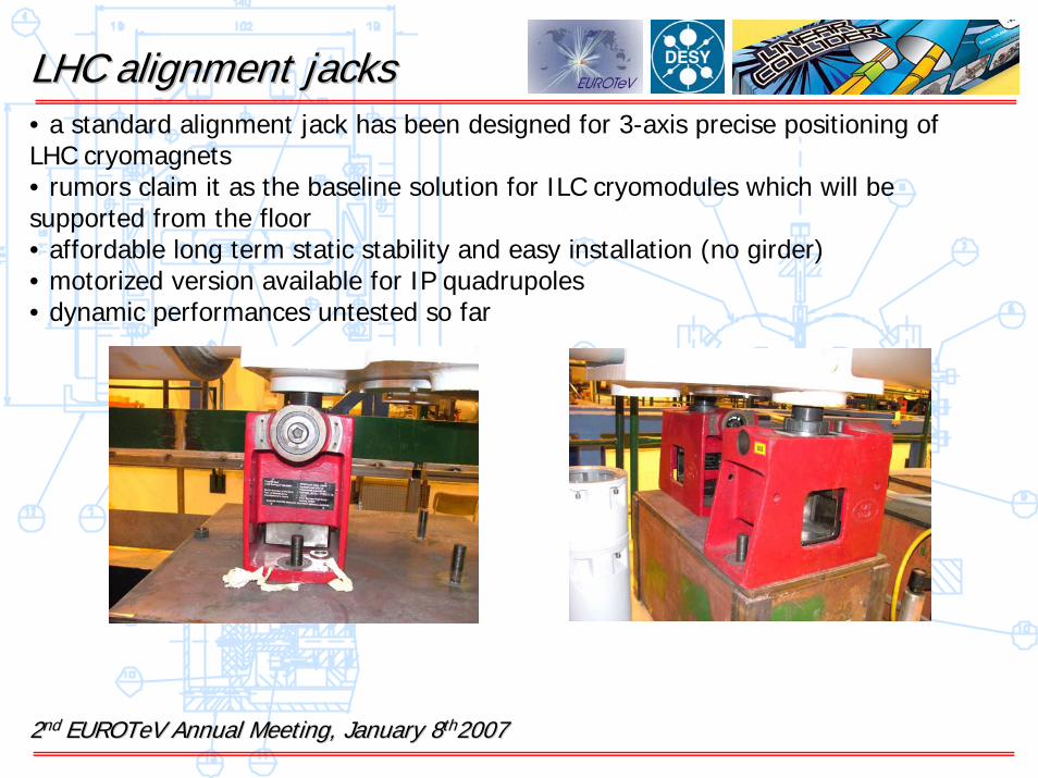
LHC alignment jacksLHC alignment jacks• a standard alignment jack has been designed for 3-axis precise positioning of LHC cryomagnets• rumors claim it as the baseline solution for ILC cryomodules which will be supported from the floor• affordable long term static stability and easy installation (no girder)• motorized version available for IP quadrupoles• dynamic performances untested so far
22nd nd EUROTeVEUROTeV Annual Meeting, January 8Annual Meeting, January 8thth20072007

LHC LHC CryodipolesCryodipoles
LHC standard cryodipole installed in the 3-4 arc section Fiberglass cold mass supports
Length 17 m
Weight 32 tons
Cryostat diameter ~ 1 m
No.of jacks 3+1 at center for sagitta compensation
Cold mass support 3 fiberglass posts on the bottom
Characteristics of LHC standard dipoles
Cold mass view22nd nd EUROTeVEUROTeV Annual Meeting, January 8Annual Meeting, January 8thth20072007

LHC LHC CryodipolesCryodipoles
22nd nd EUROTeVEUROTeV Annual Meeting, January 8Annual Meeting, January 8thth20072007
Horizontal transverse
Vertical
• Low frequency resonance at 4 Hz (Q~30) in the horizontal transversedirection. Other large amplitudemodes at 17 and 42 Hz.• Very rigid in vertical.
Stand-alone configuration
22nd nd EUROTeVEUROTeV Annual Meeting, January 8Annual Meeting, January 8thth20072007
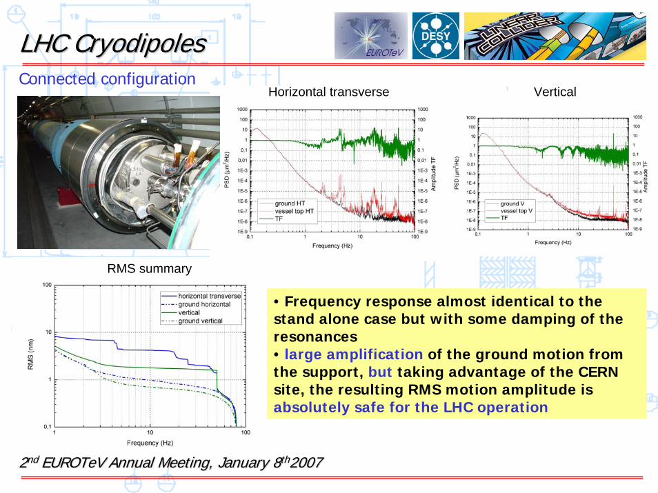
LHC LHC CryodipolesCryodipolesConnected configuration
• Frequency response almost identical to thestand alone case but with some damping of theresonances• large amplification of the ground motion fromthe support, but taking advantage of the CERN site, the resulting RMS motion amplitude isabsolutely safe for the LHC operation
Horizontal transverse Vertical
RMS summary

LHC Low LHC Low ßß QuadrupoleQuadrupole
Length ~ 9 m
Weight 17 tons
Cryostat diameter ~ 1 m
No.of jacks 3 with enlarged footing section
Cold mass support Full cross section collars
LHC low beta quadrupole next to ALICEInteraction region
View of the alignment jacks. Note the enlarged contactsection and the extra layer of concrete.
Composite spider-like cold mass support, designed for better rigidity.Characteristics of LHC low beta quadrupoles
22nd nd EUROTeVEUROTeV Annual Meeting, January 8Annual Meeting, January 8thth20072007

LHC Low LHC Low ßß QuadrupoleQuadrupole
Horizontal transverseHorizontal longitudinalGround to vessel top transfer functionGround to vessel top transfer function
Vertical
• stiffer than dipoles along the transverse
direction with the first mode at 10 Hz, but larger Q• soft in the longitudinal axis with a 7.3Hz mode• rigid along the vertical direction
22nd nd EUROTeVEUROTeV Annual Meeting, January 8Annual Meeting, January 8thth20072007

22nd nd EUROTeVEUROTeV Annual Meeting, January 8Annual Meeting, January 8thth20072007
LHC Low LHC Low ßß QuadrupoleQuadrupole
Vessel socket vs jack base
• the transverse mode structure already visibleat the interfacebetween the jack and the concrete pad, butnot in the floor• the enlarged contactsurface producessignificant benefits on the dynamic stability of the module
Effect of the support foundationEffect of the support foundation
Vessel socket vs floor

LHC MagnetsLHC Magnets--cold masscold massMeasurement on the standing alone dipole and Measurement on the standing alone dipole and quadrupolequadrupole
the cold mass motion is dominated by the large amplitude module rocking modes. In dipoles seems not veryrigidly supported internally: three modes at 8.6, 9 and 14 Hz are visible in the cold mass PSD only. Stiffer as expected the quadrupole with a lowest mode at 17 Hz. No modal shape investigation done yet.
22nd nd EUROTeVEUROTeV Annual Meeting, January 8Annual Meeting, January 8thth20072007

LHC MagnetsLHC Magnets-- SummarySummary
• we have investigated the dynamic stability of standard LHC arc section dipoles in both stand-alone and connected to the beam-line configurations• the support design with no girder and short leveling jacks has been evaluated• found low frequency mechanical resonances (4 Hz the lowest one) that largely amplifies the floor motion in the horizontal transverse direction• anyway no effect on LHC operation is expected because of the outstanding ground motion level in the tunnel• the alignment jacks look ‘undersized’ to guarantee proper vibrational stability to the 32 tons dipoles• the results of the measurements on the short low beta quadrupole cryostat look promising for the use of the alignment jacks for the ILC linacs, after suitable modifications (properly sized footing)
Thanks to: Claude Hauviller, Helene Mainaud-Durand, Jean-Pierre Quenelle, Kurt Artoos (CERN)
22nd nd EUROTeVEUROTeV Annual Meeting, January 8Annual Meeting, January 8thth20072007

XFELXFEL--hanging moduleshanging modulesXFEL Tunnel layoutXFEL Tunnel layout
*Courtesy of *Courtesy of AmbergAmberg Engineering Engineering
Connection boxes + continuous rails as Connection boxes + continuous rails as interface between the ceiling and the interface between the ceiling and the module string.
Alignment/support jigs clamped to the railsAlignment/support jigs clamped to the railsmodule string.
22nd nd EUROTeVEUROTeV Annual Meeting, January 8Annual Meeting, January 8thth20072007

XFELXFEL--jigs designjigs designTwo alternative design proposed and tested for vibrations by ourTwo alternative design proposed and tested for vibrations by our groupgroup
Pull Rod VersionPull Rod Version Bolt VersionBolt Version
22nd nd EUROTeVEUROTeV Annual Meeting, January 8Annual Meeting, January 8thth20072007
ConceptThe module is suspended by four M24 rods; three adjustment rods provide knobs foralignment in the horizontal
AdvantagesCheap, quick installation and alignment
DrawbacksHorizontal and vertical adjustment coupled;Internal resonances at low frequency
ConceptThe module is standing on three levelingbolts; the weight is supported by the twolarge cross section crossbars.
AdvantagesVery rigid, the machine is just standing in place, no static shear stresses, horizontal and vertical adjustment well decoupled
DrawbacksManufacturing costs, installation time

22nd nd EUROTeVEUROTeV Annual Meeting, January 8Annual Meeting, January 8thth20072007
XFELXFEL--Pull rod supportPull rod supportQuad end vessel top Quad end vessel top vsvs crossbeamcrossbeam
General commentRather complex transfer function due to thelack of stability of the test stand; all of thepeaks at low frequency belong due to theelasticity of the crossbeams and to their poorinterface with the concrete stands
Horizontal transverse/Vertical: coupledinternal mode at 15.5 Hz. The low frequency of the mode and the coupling prove the suspectedlimitations of this design

22nd nd EUROTeVEUROTeV Annual Meeting, January 8Annual Meeting, January 8thth20072007
XFELXFEL--Bolt supportBolt supportQuad end vessel top Quad end vessel top vsvs crossbeamcrossbeam
General commentSame effect from the test stand but no evidence for low frequency internalresonances. The rigidity of this design isconfirmed by the integrated RMS, with around20% matching in both horizontal and verticalat 1Hz.
Horizontal transverse/Vertical: very well decoupled. Benefit from the standing-likedesign
Horizontal Transverse RMSHorizontal Transverse RMS
Horizontal TransverseHorizontal Transverse

ConclusionsConclusions
• the dynamic stability of the quadrupoles is a crucial parameter for beam jitter at the output of the ILC and XFEL linacs; more critical for the XFEL with 0.1σtolerance at the input of the undulator
• the dynamics of the quadrupoles is dominated by the low frequency modes of the cryomodule on ist support system. A careful design should be implemented to avoid resonances below 10 Hz, at least.
• which support design choose for the ILC? TTF style looks inadequate. We haveinvestigated on the stability of LHC cryomagnets: not as good as claimed, but a viable way for the ILC with some changes in the design.
• a vibrationally stable support/alignment jig for the XFEL cryomodules has beentested; a machine hanging from the ceiling and hosted in a single tunnel looksfeasible.
22ndnd EUROTeVEUROTeV Annual Meeting, January 8Annual Meeting, January 8thth 20072007

Thanks to:Thanks to:
R. Lange, K. Jensch, W. Maschmann, H. Hintz (DESY-MKS)H. Hirsemann, N. Meyners, M. Schlösser, B. Sparr (DESY-MEA)D. Samberg (HASYLAB)S. Wendt (Technische Universität Hamburg- Harburg)
*Financial support from EuroTeV: Work supported by the Commission of the European Communities under the 6th Framework Program ‘Structuring the European Research Area’, contract number RIDS-011899.
2nd 2nd EUROTeVEUROTeV Annual Meeting, January 8Annual Meeting, January 8thth20072007