Embed Size (px)
Citation preview

Mixer Anatomy 101 In writing about mixers, we authors tend to toss around technical terms as if the readers knew what we were talking about. This article was originally written for the 1996 “Mixers” issue of Recording Magazine, so the editor decided that it was time for a detailed discussion about mixers (of course we’re talking analog here, before analog was cool). What follows is a discussion of common terms used to describe the workings of a mixer such as preamp, bus, channel, insert, path, group, equalizer, and in-line and split monitoring. We’ll then follow the block diagram of a Mackie 1604VLZ series mixer to show the various signal paths, inputs, and outputs. If you own a mixer, or are drooling over a sales brochure, this article will help you to understand how to follow a block diagram and learn what a mixer will and will not do for you. Mixers come in many shapes and sizes, from palm-sized to studio consoles several yards long, but they have a lot in common. A simple stereo mixer has the same basic functions as the monsters used for building a movie sound track from 96 tracks of audio, a dozen tracks of dialog, and hundreds of sound effects. The bigger console has more inputs and outputs, but it mixes just the same as one you might have in your tabletop studio. One mixer might be overkill for some projects, and be stretched thin to handle others.
Mixer? Or Console? We tend to use these terms interchangeably, and for the most part, the differences are in how the device is used. Both have mixing functions, but since a console generally functions as the control center for a recording studio, it often has more knobs and switches to provide control over several mixes, each of which has its own purpose during different phases of a production. There’s no benchmark point of complexity at which a mixer becomes a console. Use whatever term makes you comfortable. That’s what I do. This article was originally written when multitrack recorders, both analog and digital, had become affordable for personal use, but multitrack DAWs were in their infancy. It was still common to build a multitrack recording facility around a mixer with multiple outputs as well as multiple inputs, often with a separate section dedicated to monitoring while tracking. While today it’s possible (and typical) to build a studio based around software that performs most of the functions of a hardware mixer, there are several benefits to incorporating a mixer in your setup. Even if you choose not to use a mixer in your system, understanding its functions will help you to understand the multitrack recording and mixing process. While a hardware mixer is no longer an indispensable part of a recording system, often an “old school mixer” approach offers great flexibility in signal routing that are often missing from today’s highly integrated digital interfaces. Understanding what goes on under that panel full of knobs will help you to choose what’s appropriate for your work.

The Basic Framework - Buses A bus can be defined as a conductor or set of parallel conductors that forms a main transmission path. The term “bus” is common in many electrical technologies. Your computer has several buses which distribute data and control signals among the various motherboard modules and plug-in cards. The circuit breaker box in your basement has buses which distribute electrical power from the pole on the street to the various circuits in your home or studio. The word has only one “s” (no kissing, but today “busses” has become acceptable if you prefer) - it comes from the British “omnibus”, a common carrier. The fundamental purpose of a mixer is to combine signals from several sources to one or several outputs. The point at which they’re combined is the bus. In the simplest monophonic mixer, all of the input signals are sent, after adjusting their relative volumes, to a single bus, from which the output is taken. In a stereo mixer, left and right channel signals are combined to a pair of buses, which correspond to the mixer’s left and right outputs. In a 4 or 8-bus mixer typically used with a multitrack recorder, each input can be assigned to one or more buses. Those buses feed various things around the studio, including the channels of a multitrack recorder, effects processors, players’ headphones, and the studio monitor speakers. Every bus has one or more inputs and one output. Examine the block diagram of just about any mixer and somewhere near the center you’ll find a series of vertical parallel lines with a series of horizontal lines going off from them in both directions. The vertical lines represent the mixer’s buses. The horizontal lines coming from the left (usually) represent paths from signal sources feeding the bus while the lines going toward the right represent paths away from the bus which ultimately feed the mixer’s outputs. The number of buses is a good measure of the level of complexity of the mixer. A basic stereo mixer has a main left and right bus, and perhaps a couple of auxiliary buses for effects or monitor mixes. A multitrack recording console typically has more auxiliary or monitor buses, as well as subgroup buses. The important thing to recognize is that every mixer bus has more than one input, and one output, though that output may have more than one destination (which might be another bus). Hey! What gives!? You looked at the block diagram of your 8-bus console and saw seventeen vertical, parallel lines, not just eight? Did they send you the wrong manual? Well, the advertising people decided that “bus” was a cool term, but they usually designate a mixer by the number of output or subgroup buses, and there are eight of those. Typically it also has a pair of buses for the main stereo output, a bunch of auxiliary send buses, perhaps a PFL bus and solo bus, too.
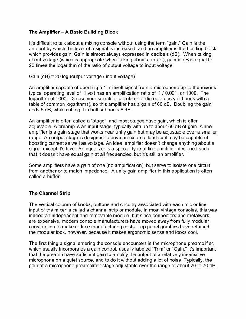
The Amplifier – A Basic Building Block It’s difficult to talk about a mixing console without using the term “gain.” Gain is the amount by which the level of a signal is increased, and an amplifier is the building block which provides gain. Gain is almost always expressed in decibels (dB). When talking about voltage (which is appropriate when talking about a mixer), gain in dB is equal to 20 times the logarithm of the ratio of output voltage to input voltage: Gain (dB) = 20 log (output voltage / input voltage) An amplifier capable of boosting a 1 millivolt signal from a microphone up to the mixer’s typical operating level of 1 volt has an amplification ratio of 1 / 0.001, or 1000. The logarithm of 1000 = 3 (use your scientific calculator or dig up a dusty old book with a table of common logarithms), so this amplifier has a gain of 60 dB. Doubling the gain adds 6 dB, while cutting it in half subtracts 6 dB. An amplifier is often called a “stage”, and most stages have gain, which is often adjustable. A preamp is an input stage, typically with up to about 60 dB of gain. A line amplifier is a gain stage that works near unity gain but may be adjustable over a smaller range. An output stage is designed to drive an external load so it may be capable of boosting current as well as voltage. An ideal amplifier doesn’t change anything about a signal except it’s level. An equalizer is a special type of line amplifier designed such that it doesn’t have equal gain at all frequencies, but it’s still an amplifier. Some amplifiers have a gain of one (no amplification), but serve to isolate one circuit from another or to match impedance. A unity gain amplifier in this application is often called a buffer.
The Channel Strip The vertical column of knobs, buttons and circuitry associated with each mic or line input of the mixer is called a channel strip or module. In most vintage consoles, this was indeed an independent and removable module, but since connectors and metalwork are expensive, modern console manufacturers have moved away from fully modular construction to make reduce manufacturing costs. Top panel graphics have retained the modular look, however, because it makes ergonomic sense and looks cool. The first thing a signal entering the console encounters is the microphone preamplifier, which usually incorporates a gain control, usually labeled “Trim” or “Gain.” It’s important that the preamp have sufficient gain to amplify the output of a relatively insensitive microphone on a quiet source, and to do it without adding a lot of noise. Typically, the gain of a microphone preamplifier stage adjustable over the range of about 20 to 70 dB.
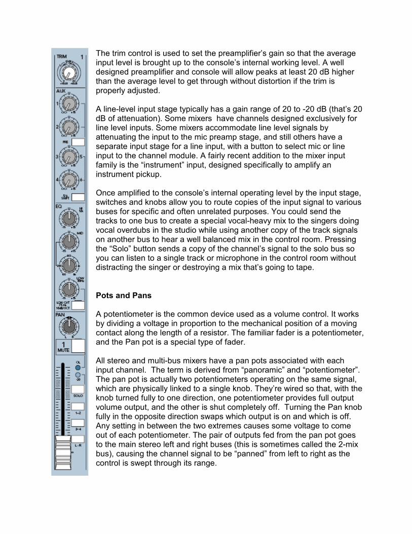
The trim control is used to set the preamplifier’s gain so that the average input level is brought up to the console’s internal working level. A well designed preamplifier and console will allow peaks at least 20 dB higher than the average level to get through without distortion if the trim is properly adjusted. A line-level input stage typically has a gain range of 20 to -20 dB (that’s 20 dB of attenuation). Some mixers have channels designed exclusively for line level inputs. Some mixers accommodate line level signals by attenuating the input to the mic preamp stage, and still others have a separate input stage for a line input, with a button to select mic or line input to the channel module. A fairly recent addition to the mixer input family is the “instrument” input, designed specifically to amplify an instrument pickup. Once amplified to the console’s internal operating level by the input stage, switches and knobs allow you to route copies of the input signal to various buses for specific and often unrelated purposes. You could send the tracks to one bus to create a special vocal-heavy mix to the singers doing vocal overdubs in the studio while using another copy of the track signals on another bus to hear a well balanced mix in the control room. Pressing the “Solo” button sends a copy of the channel’s signal to the solo bus so you can listen to a single track or microphone in the control room without distracting the singer or destroying a mix that’s going to tape.
Pots and Pans A potentiometer is the common device used as a volume control. It works by dividing a voltage in proportion to the mechanical position of a moving contact along the length of a resistor. The familiar fader is a potentiometer, and the Pan pot is a special type of fader. All stereo and multi-bus mixers have a pan pots associated with each input channel. The term is derived from “panoramic” and “potentiometer”. The pan pot is actually two potentiometers operating on the same signal, which are physically linked to a single knob. They’re wired so that, with the knob turned fully to one direction, one potentiometer provides full output volume output, and the other is shut completely off. Turning the Pan knob fully in the opposite direction swaps which output is on and which is off. Any setting in between the two extremes causes some voltage to come out of each potentiometer. The pair of outputs fed from the pan pot goes to the main stereo left and right buses (this is sometimes called the 2-mix bus), causing the channel signal to be “panned” from left to right as the control is swept through its range.

Groups and Subgroups In a basic stereo mixer, channels are routed via pan pots to a single pair of buses from which the main stereo output is taken. In a 4-bus console like our Mackie 1604VLZ, switches are provided to send the pan pot’s outputs to your choice of pairs of “group” buses (two pairs on a 4-bus console, four pairs on an 8-bus, and so on), in addition to the main stereo buses. One common studio setup is to connect the outputs of the group buses to the inputs of a multitrack recorder, one output per track, using the pan pots and bus assignment switches to send any input to any tape track. In these days of one-track-at-a-time recording, smaller consoles, and relatively inexpensive tracks, it’s fairly common to “mult” recorder inputs, for example connecting group output 1 to recorder inputs 1 and 4, group output 2 to recorder inputs 2 and 5, etc. This allows you to use the mixer as a convenient signal router when tracking by using the panpots and bus assign switches to freely assign any input source to any one or two of the output buses. Most multi-bus consoles have the ability to route the output of the group buses to the main stereo bus. In this configuration, the group outputs become “subgroups”, and the group faders become “submasters”. A submaster fader adjusts the level in the main stereo mix of the mix of all the sources which have been assigned to that subgroup. For example, assign all the background vocal tracks (or inputs, if you’re working on a live mix) to a subgroup pair, using the channel pan and balance controls for good blend. Then, by assigning that pair of submaster faders to the main stereo mix, you can adjust the level of the background vocals in the full mix using just the subgroup faders rather than having to manage a handful of faders, one for each background vocal part.
Auxiliaries Nearly all consoles have one or more auxiliary (“Aux”) buses with their associated controls. These are typically used for mixes that don’t go directly to tape, but which are still important to the recording and mixing process. Common applications are to send channel signals to an effects processor, or to create a special mix for musicians’ headphone feeds so that they can better hear parts that they’re trying to blend with or play against without being distracted by other things going on in the production. When mixing a live show, the auxiliary buses typically are used to create unique mixes that the musicians on stage hear from the monitor speakers.
Tape Monitoring OK, it isn’t always tape, but that’s a convenient term when talking about recording. The primary thing that most distinguishes a multitrack recording console from other types of mixers is its tape monitoring facilities. With a basic stereo mixer, you set up a bunch of microphones or other sound sources, mix them so that they sound good, perhaps add

Update: Now that 24-bit recording is pretty much the norm, it’s no longer important to record tracks as hot as possible, and in fact, it’s not advisable. Digital recordings sound better and mix easier when leaving some headroom. Still, you should shoot for a consistent nominal record level on each track.
effects, and send the whole mix out a pair of outputs (or a single output if you’re doing a mono production) to a recorder or speaker system. What you mix is what you get. In the multitrack recording process, however, we often record only a single instrument or voice on a track. After all the parts are recorded, either in a single pass with everyone playing at once or one or a few parts at a time, those recorded tracks are mixed to produce the final recording. During the process of recording the individual tracks (“tracking”), It’s necessary to hear what you’ve already recorded so that you can make the new parts fit. In essence, you’ll be mixing, at least roughly, as you’re recording, so the mixer needs to be able mix both inputs from the sources you’re recording and the playback from the recorder at the same time. If you’re doing a good job of engineering, you’ll record each track as “hot” as possible in order to achieve the best signal-to-noise ratio when using an analog recorder or the best low level resolution if recording digitally. This means that the tracks will all be at approximately equal volume, something that isn’t necessarily very musical. You’ll change that when you mix your tracks, but, while tracking, you’ll still want to hear something that makes musical sense. This is where the monitor section comes in. In a multitrack recording environment, what we listen to while tracking is a mix of what’s on (or being fed to) the recorder rather than the actual microphone inputs. In this way, record at the optimum level while listening to a musical mix. By using auxiliary buses, we can also create custom headphone mixes of the tracks and input sources, offering the players a mix that allows them give their best performance in the studio. Multitrack consoles have a dedicated set of tape inputs which, during tracking, are routed to a dedicated monitor section to create the monitor mixes. For final mixdown, the tape inputs are switched (with a button – no re-patching required) to the main section of the console to permit using the console’s full set of mixing capabilities. Two different architectures (or design philosophies) for multitrack recording console design have become popular, both related to the physical format of the tape monitor mixing section. These are called “split” (or “side-by-side”) and “in-line” consoles. Split monitoring is also sometimes known as “British style” (not to be confused with “British EQ”) because it first appeared on the earliest large multitrack consoles, which came from across the pond. In-line monitoring is sometimes called “American style” because it was developed a little later by US manufacturers, initially by Harrison Consoles and popularized by MCI. A split console has a distinct group of controls dedicated to monitoring the multitrack recorder outputs during the tracking process. It looks like a smaller mixer was bolted along side the main mixer, and indeed that’s how this style of multitrack monitoring originated. This “sidecar” mixer has, at minimum, level and pan controls for each track, but often not much more. The output of the monitor mixer usually feeds the main stereo

bus, where it can be sent to the control room’s monitor speakers and the mixdown recorder so that rough mixes can be recorded during the tracking session. While a split console may have 24, 36 or more input modules, its monitor section is almost always smaller, typically 16 or 24 inputs, corresponding to the typical 16 or 24 track recorders with which it was designed to work. A 48-channel monitor section on a split console, while not unheard of, is pretty unwieldy. Most of today’s multitrack consoles are of the in-line style. An in-line console, like a split console, provides a separate mix (often called Mix B) of the recorder returns, but unlike the split console, all of the controls and circuitry associated with both the channel’s line/mic input and the tape monitor sections are grouped together in a single channel module. It took a while for engineers to get used to the design, but the in-line design has two big advantages over the split console: First, without the extra monitor mixer section adjacent to the main channel modules, the console takes up less space. Second, since every input section has a set of controls for mixing the recorder outputs, you are able to monitor and mix as many tape tracks as you have input modules. With today’s modular digital multitracks, adding more tracks isn’t the large investment that it used to be. It’s often as simple as borrowing another recorder from a band member and hooking it up. With a split console, even if you have enough channels to mix down all the extra tracks you hauled in for the project, you might have to add an outboard mixer so you can hear all the recorded tracks during the tracking process. With an in-line console, if you have enough inputs to mix your tracks, you’ll have enough inputs to monitor them. The controls dedicated to tape monitor mixing on either style console are usually pretty minimal, often only rotary controls for level and pan. Sometimes an auxiliary send or two is provided so you can add reverb or an effect to the monitor mix, and occasionally, there’s low and high EQ, but nothing fancy. Alternately, there may be a button to switch part (or all) of the main channel equalizer into the monitor channel. A “flip” or “fader reverse” button is a powerful feature found on many in-line consoles. When the console is “flipped”, the small rotary pot controlling the track’s level in the monitor gets swapped with the main channel fader. When tracking, once you’ve set the gain for proper record level, you usually don’t have to “ride” the level sent to the recorder unless you’re working with a particularly wild singer. So why not use that nice slide fader for your monitor mix just as you’d use during the final mixing process, and use the dinky little rotary pot to set the record level? Makes good sense! You might lose the ability to equalize the signal going to tape in the swap, but in today’s megatrack environment, most engineers tend to record tracks flat (with no equalization) and apply EQ only when doing the final mix. On some consoles, the “flip” switches swap the entire monitor and main channel signal path so that, when tracking, you have all the controls available for monitor mixing that you have when doing the final mixdown. With all the tools available, including

automation if your console is so equipped, you can start developing your mix while the singer is trying for the twentieth time to get the phrasing just right. The in-line console has distinct advantages over the split design in size and cost, both important to entry level buyers. Experienced engineers, however, often find that the split console configuration is the easiest to work on when tracking a fast moving multitrack session. Visit Capitol Records and you’ll see both styles. Visit Joe’s Garage and you’ll probably find a modern, moderate priced in-line console. [21
st Century update
– visit Joe’s Spare Bedroom and you’ll likely find no console at all.]
Reading The Blocks One of the goals for this article is to get you sufficiently familiar with the functional blocks of a mixer so that you can by studying its block diagram, you can figure out what capabilities it has, and what use you can make of it’s various inputs, outputs and controls. The mixer we’ve chosen for our example is the Mackie 1604-VLZ. Although it’s neither a classic split or in-line design, it contains all the major elements you’ll encounter on just about any mixer. We won’t trace every line, just enough to get you familiar with the symbols and the process, and you can take it from there. A block diagram isn’t a schematic diagram, pictorial, or assembly drawing, but it contains elements of all of them. It won’t tell you anything about the noise figure of an amplifier stage or how many bits an A/D converter uses, but it will show you how a signal gets from one point to another, what switches and controls are in the path, and what inputs and outputs it has. Since a mixing console contains a lot of copies of the same circuitry, typically a block diagram will show only the first of many identical circuits. If a console has 16 identical input channels, expect to see only one or two shown on the block diagram. If there are four subgroup buses, although all the buses will be shown, you may see only one subgroup fader, insert jack, and output. You’ll have to go to the spec sheet to find out how many “duplicates” there are.
Symbology The electronic industry uses standard symbols for schematic diagrams. Block diagrams aren’t quite as standard, though, so you’ll have to dope out a certain amount of basic information on your own. In the case of the Mackie block diagrams, input and output connectors are shown with their standard schematic symbols. Since all of the 1/4” jacks on the VLZ are of the tip-ring-sleeve construction, they’re illustrated as such. Not everybody does this, so if a spec sheet says an input is balanced and the block diagram shows a single circuit jack (or just a block or an arrow), you have to trust ‘em. Mackie uses a circle with an arrow diagonally across it to represent a rotary control, and similarly a vertically oriented rectangle with the diagonal arrow to represent a slide fader. In general, an arrow through a symbol indicates that whatever the symbol

represents is adjustable. Switches are represented by a “wiper” pivoted at one end, with the other end pointing at one of the possible positions that the switch can be in. All the switches on the VLZ are two-position switches, meaning that the wiper connects its input to either of two outputs, (or connects its output to one of two inputs) one of which might be an open circuit (the switch is “off” in this position). You may find multi-position switches on other block diagrams. They look similar to the two-position switches found on the VLZ only there are more than two possible destinations for the signal that’s applied to the wiper. Amplifiers are represented by triangles with the point going in the direction of the signal flow. In the interest of settling “pin 2 hot” arguments, Mackie illustrates amplifiers with balanced inputs by showing two leads, labeled + and -, going into the triangle symbol. The amplifiers with the Greek letter sigma inside the triangle are “summing” amplifiers. A summing amplifier has a gain of 1 (unity, or 0 dB) unless it needs to make up some gain lost when summing several signals that are on a bus. Sigma is the mathematical symbol for summation. It’s kind of a free-for-all with other components. Resistors or attenuators (which may be a group of resistors) are shown on the VLZ block diagram as rectangles, capacitors use their standard schematic symbol, and indicator lights look like little suns. If you know what to expect, you can usually figure out what a symbol means. Block diagram convention is for signals to flow from left to right and from top to bottom, so you’ll usually find inputs on the left side of the diagram and outputs on the right. Sometimes, though, the art department takes liberties with this to make the diagram fit on the page. Since just about everything in a mixing console goes through a bus, the buses are in the middle, with inputs coming from the left side, and outputs leaving toward the right. A dot at the intersection of two lines indicates a connection, but lines crossing without a dot just cross on their way from one place to another.
The Route From Gozinta to Gozouta The main signal path through the mixer starts with the mic or line input, and ultimately ends up at the main left and right outputs. We’ll trace though this path first. The input section of the channel is located in the upper left corner of the block diagram. The signal from the mic connector goes through a pair of capacitors (it’s a bit unusual to show those capacitors on a block diagram) and into the first amplifier in the chain, the mic preamp. The mic input connector is also wired, through a pair of resistors, to the phantom power supply to provide the operating voltage to condenser microphones [today, some ribbon microphones have a built-in preamplifier which is powered by the phantom power supply]. The capacitors between the mic connector and the preamp are there to keep the phantom voltage away from the mic preamp stage and to assure that you won’t “power” a line input, possibly damaging the equipment you connect to it. The “Global switch” notation next to the Phantom Power switch. This means that power to all sixteen

So you have a fancy outboard mic preamp. Since you’re expecting it to be better than the mixer’s preamps, you want to avoid the internal preamp, right? Well, it’s really not so bad, because most of the characteristic sound of a preamp results from the interface between the mic and the preamp, and your mic is still connected to your outboard preamp. Arguably, you’re adding a bit more noise, but in most cases, it’s insignificant, and you have the advantage of a balanced input for your outboard preamp’s output. Don’t sweat it unless you have a problem. Note that many modern mixers targeted as the hub of a tabletop studio have fewer mic preamps than input channels, and have line inputs arranged as stereo pairs, with one channel strip controlling both. Know how your inputs are counted. A mixer sold as “12 channel” may have only 4 mic inputs and 4 pairs of line inputs.
of the mic inputs are controlled by a single switch. Other mixers have a dedicated phantom power switch for each mic input. The first amplifier block represents the mic preamp section. The associated rotary control is the input Trim control which adjusts the preamp gain, bringing the low level microphone signal up to the internal operating level of the console. The line input jack is located just below the mic connector is. Note that the signal goes from the jack, through a pair of resistors, directly to the input of the mic preamp. These resistors attenuate the level of the line input signal to approximately the same level as a microphone. Indeed, a source connected to a line input always goes through the mic preamp on our example mixer, and on most other mixers in the “project studio” price class. Few have dedicated, selectable lower gain line input stages. The channel insert jack follows the preamp. An Insert jack allows you to break into the signal path and insert a compressor or some other signal processor. Although this jack looks like the same tip-ring-sleeve type as the line input (and, indeed it is), it’s used in a different way. The tip and ring contacts are “normalled” together by switches built in to the jack, so that with nothing plugged in, the signal flows straight through as if the jack wasn’t there. Inserting a plug pushes the switch contacts open. The tip contact of the plug carries the output of the preamp out to the input of the outboard signal processor, while the ring contact carries the signal processor’s output to the input the next stage. Take a close look at how the switches on that Insert jack are wired. Normally, you’d insert the plug fully, both switches would open, and you’d get the circuit path described above. But if you inset the plug only half way, something interesting happens. Let’s follow the signal path on the block diagram. The preamp output goes to the tip (rearmost) contact of the jack, which is connected through one of the jack’s switches to the ring contact. Since the ring contact is connected directly to the next stage of the mixer, inserting the plug half way doesn’t break the signal flow, however it allows us to access the output of the mic preamp by itself. This the purest signal that we can send from this console to a recorder. Insert jacks wired in this manner are often used as “direct” outputs. It’s important to note the location in the circuit of the insert jacks on your console. They may come later on in the chain, which will affect they way you use them. Following the insert jack is a low-cut filter which can be switched in or bypassed. The equalizer stage follows the filter. On this mixer, the equalizer is always in the signal
path. Some mixers provide a bypass switch to take the equalizer out of the chain. Bypassing the EQ will allow you to compare the equalized and flat signal easily. And if it’s not being used, bypassing the equalizer will get rid of any noise contributed by it’s associated amplifiers. A mute switch follows the equalizer. This is simply an on/off switch which disconnects the input, up to the equalizer, from everything past the switch. Next comes the main channel fader, which feeds the pan pot. The pan pot splits the signal into two paths, which are routed to your choice of buses by the bus assign switches.
Hopping On And Off The Bus The bus assign switches operate in pairs, as indicated by the dotted lines connecting each pair of switches. Pressing the upper (L/R) switch connects the pan pot’s two outputs to the main Left and Right buses. The other bus assign switches send the pan pot outputs to subgroup buses 1/2 and 3/4. Remember that although the block diagram shows only one input channel, in reality there are sixteen channels with their associated bus assign switches. Just below the first pair of bus assign switches you’ll find two horizontal lines going off to the right. Notice the dots indicating that they’re connected to the main left and right buses at the left end, but they simply cross over all the other buses on their way to the Main Mix summing amplifier. That’s where all the signals assigned to a given bus are combined. The summing amplifier outputs go through another set of insert jacks which allow the full stereo mix to pass through a signal processing device (typically a compressor or equalizer). From there, the mix goes to the master left and right faders, and through a final set of amplifiers to the output connectors. Take a good look at the main L/R outputs. The amplifiers feeding those jacks are represented by a pair of overlapping triangles rather than a single triangle, with one “point” feeding the tip terminal of the output jack and the other “point” feeding the ring. This is Mackie’s way of showing an amplifier with a balanced output. The outputs of the left and right summing amplifiers are combined through two resistors to make a monophonic mix. The left + right sum goes to a level control, through another amplifier, to the mono output. The two resistors serve to isolate the left and right channels from each other so the main outputs don’t become mono also. Compare those main and mono output jacks to the Control Room output jacks just below them. You’ll see that the control room output jacks are fed directly from summing amplifiers (which have a single output), and the summing amp is connected to the tip terminal of the jack. The ring terminal of the jack is connected to the sleeve (ground) through a resistor. This is a simple way to make a balanced output. Though not quite

This is an “old school” direct output routing, which Mackie has stuck with through the current VLZ3 series. Most direct outputs are more direct, with a tap taken at the mic preamp output, pre-everything.
perfect, when connected to a balanced (differential) input, it offers a substantial amount of hum and noise rejection over a simple unbalanced output for the cost of a resistor. This is a level of detail that isn’t often found on a block diagram, but it’s nice to when they’re shown.
Alternate Routes We used the Mackie 1604 VLZ series for this discussion because it’s a simple, but fairly conventional four-bus design, which is actually six when you count the main left/right buses. However, on Mackie’s earliest mixer in this series, and the models with fewer than 16 input channels, they came up with a bus routing scheme that I call “semi-4-bus.” At the time, there really wasn’t a lot of need for a true four bus mixer, so to lower the cost, they put four buses inside, but left off some controls. The signal flow is essentially the same as the main left/right buses in the 1604 VLZ, but instead of three bus assign switches, there’s only one, and it’s labeled MUTE. Pressing that button switches the channel signal from the main L/R bus to the Alternate buses 3-4. Those buses don’t have any metering or a master fader, but they’re a convenient way to feed a signal to a sound card, and it can serve as a submaster. A number of other manufacturers have adopted this system in their smaller mixers.
Other Routes Remember we said that a signal in a mixer could be “copied” for use in more than one place? Let’s look at some alternate paths. You’ll see a point between the fader and pan pot where the signal branches off to become the Direct Output. An exception to the “inputs on the left, outputs on the right” convention, the Direct Output jack is located on the left side of the diagram just below the line input. Arrows along the path show us the direction of signal flow. Since the direct output is taken after the fader, which is after the equalizer, we say it’s “post-fader and post-EQ”. On the VLZ, not all of the auxiliary sends and returns have identical signal paths. We’ll walk through those with a straightforward path, and for homework, you can trace through the others. The Auxiliary Sends are copies of the input signal. There are six Aux Send buses, but they are shared by four controls. The same post fader/EQ signal feeding the Direct output goes to the lower two Aux Send pots. The output of the third pot goes to a switch which sends the signal to either the Aux Send 3 or Aux Send 5 bus. Similarly, the fourth pot can be switched to feed Aux Send 4 or Aux Send 6. Auxiliary Sends 1 and 2 have a switch to select the input source to the upper two Aux Send controls. In one position, Aux 1 and 2 use the same “post” signal that feeds Aux 3-6, and in the other position, it takes a tap off the signal coming out of the insert jack, which is pre- fader and pre-EQ, but post-insert. Auxiliary Returns typically have a fairly simple signal path with rarely more than a buffer amplifier and a level control between the Aux Return jack and the main stereo bus. The
VLZ adds a bit more flexibility with a pair of switches associated with Aux Return 3. In one position, the signal goes to the main L/R bus. In the other position, the second switch is active to send the return signal to either subgroup bus 1-2 or 3-4. Aux Return 4 has a switch to send the return signal either to the main bus (the conventional route) or just to the control room and headphone monitor outputs. Generally this is sufficient for mixing, but for live PA or recording, where you have monitors fed from auxiliary sends, you might want to be able to put some reverb in the wedges or headphones. One way to skin this cat is to connect the reverb output to a channel (or two if you want stereo reverb), which makes the reverb available to send to the auxiliary bus that feeds the monitors. But the VLZ series mixers (and, you’ll find this idea adopted by other manufacturers) have a clever solution. Get out your block diagram and follow along. Aux Returns 1 and 2 each have a pair of mono summing resistors. This mono return signal goes through a level control an on to an auxiliary send bus. That sounds confusing but there’s a method in the madness. If you use Aux Send 1 to feed a wedge monitor on stage and send the singer’s channel out to a reverb unit connected to Aux Send 3, then connect the reverb’s output to Aux Return 1, you can use that EFX to Monitor control on Aux Return 1 to send some reverb to the wedge mix. It helps to clear your head if you understand that Aux Send 1 doesn’t necessarily have to correspond to Aux Return 1.
Tape Monitoring The primary feature that distinguishes a multitrack recording console from a general purpose mixing console is that the recording console has provisions for listening to a mix of the recorded tracks at any time during the recordings process (as well as the mixing process, of course). When tracking, the monitor mix is built primarily from what comes out of the multitrack recorder, or today, the DAW. The live source (mic or line input on the console) is mixed with the recorder outputs so you can hear your singing or playing while listening to the previously recorded tracks. Whether you use a recorder and console or work entirely “in the box,” this monitoring principle is fundamental to the multitrack recording process. If you understand this concept, setting up DAW tracks for Input, Output, or, with some programs “Tape style” monitoring will make sense. The Mackie 1604-VLZ that we’ve been tracing through isn’t a true multitrack recording console, so you won’t find a tape monitor path on the block diagram. That’s not to say that you can’t use it as one, and many have, and do, but you’re limited in the number of tracks you can monitor. In the days when an 8-track recorder was standard fare in a project studio, a common setup was to use eight channels of the 1604 for mic or line inputs, and the other eight channels as the multitrack recorder returns. This turns it into a “split monitor” style console.

In operation, signals usually go in one direction only, from input to output. But sometimes when plodding through a busy diagram, it’s more convenient to see where a signal comes from than where it goes. We’re following this one “backwards” to
In order to follow a true tape monitoring path, we’ll examine the block diagram of the Soundcraft Ghost. You’ll see much in common with the Mackie diagram, but there are a few significant differences. First, notice the separate Tape Input below the Mic and Line input connectors. This is where you’d connect the outputs of your multitrack recorder. Both the mic/line and tape inputs go to a switch marked “REV”. The switch is shown in its “normal” position. Follow the mic/line path through the switch contacts as they’re shown in the block diagram, and you’ll see that the console mic/line input signal follows a path similar similar to what we traced through the Mackie. Now, look at the signal from the Tape Input. It goes through a different set of contacts in the REV switch and, with the switch in its normal position, it follows a different path which ultimately leads to the “tape mix.” That LF/HF EQ block in the Tape signal path is a feature of a number of consoles of this type. The equalizer can be split into two sections, with the mid-band equalization controls always in the main signal path, but allowing the low and high frequency bands (as a pair) to be switched into the tape monitor path. This lets you apply a little EQ to your monitored signal without affecting what’s going on to tape. The Ghost block diagram, for clarity (including the switch would be cumbersome), shows the LF/HF EQ block twice, once in the main or “channel” path, and again in the monitor path. In reality, both are the same set of components. From the equalizer, or straight through if it hasn’t been switched in, the signal goes through the Mix B fader, to a pan pot, and off to the Mix B bus where it’s mixed with other tape tracks. The Mix B can be used for many things, but let’s look at its function as a tape monitor during tracking. We need Mix B to feed the control room and/or headphone outputs, so lets trace it backwards from there. Locate the headphone jack along the right hand side of the diagram. Working back toward the bus from the headphone jack, we see amplifiers, the Dim switch (this lowers the monitor volume in one large step so you can “dim” the sound and have a conversation while the music is playing), the control room level control, and a bit ahead of that, a switch (represented here as a block rather than as the diagram of a switch) marked “Control Room Source Select”. One of the selections is (aha!) Mix B. Follow that pair of lines upward from the MIX B input of the switch and you’ll see that they connect to the Mix B Master fader. The Mix B fader is fed from the Mix B summing amplifiers, which get their inputs from the Mix B bus. The Mix B Master fader also goes to a set of independent outputs, and, via the “Mix B to Mix” switch, be added to the main L/R mix. During tracking, recorder inputs typically come from the main channel path using either the group buses or direct outputs (or directly from an outboard mic preamp) and you’d

monitor what’s on (or going to) tape through the Mix B path. Now. lets rewind back to the left side of the diagram and look at what happens during mixdown. Here’s where that mysterious REV switch comes into play. The REV switch swaps the paths of the tape and mic/line input signals. Image the switch wiper is in the opposite position from what’s shown on the block diagram. Now when you trace the path of the Tape signal through the REV switch. you’ll see that instead of going through the Mix B path, it now goes through the main channel path. This gives you access to the console’s full equalizer, subgrouping, and auxiliary sends for mixdown. Since the REV switch actually does a swap, the mic/line inputs are routed through the Mix B path, allowing you to use them for additional effects returns, inputs from samplers to fly in sound effects, or perhaps “virtual tracks” from sequenced synthesizers running in sync (try saying that fast) with the tape. That “Source” switch just before the equalizer block in the Mix B path selects whether the Mix B signal comes from the REV switch or directly from the channel path. By switching it to the channel positon Mix B can be used as an additional set of stereo auxiliary sends as well as feed the stereo Aux 8 bus.
Going Fishing An astute philosopher once said something like: “Give a man a fish and he’ll have a meal for a day. Teach a man to fish and he’ll never go hungry.” If can read a block diagram (assuming you can find one, and it’s reasonably complete and accurate), you can easily determine what capabilities a piece of equipment has and learn a lot about how it functions.

Mackie 1604VLZ-Pro Block Diagram

Soundcraft Ghost Block Diagram