Embed Size (px)
Citation preview

Implementation and Evaluation of a MAC
Scheduling Architecture for IEEE 802.16
WirelessMANs
by
Abhishek Maheshwari
Department of Computer Science and Engineering
Indian Institute of Technology Kanpur
May 2006

Implementation and Evaluation of a MAC
Scheduling Architecture for IEEE 802.16
WirelessMANs
by
Abhishek Maheshwari
A thesis
presented to the Indian Institute of Technology Kanpur
in fulfillment of the
thesis requirement for the degrees of
Bachelor of Technology and Master of Technology
in
Department of Computer Science and Engineering
IIT Kanpur, India, May 2006

Abstract
A worldwide demand for high speed broadband wireless systems across commercial and
residential regions is emerging rapidly due to the increasing reliance on web for informa-
tion, business, entertainment and new upcoming high bandwidth intensive or real-time
applications. The IEEE 802.16 WirelessMAN standard which has emerged as Broadband
Wireless Access (BWA) solution, is promising to meet all such requirements and becoming
the most popular way for wireless communication. The IEEE 802.16 advantages includes
variable and high data rate, last mile wireless access, point to multipoint communication,
large frequency range and QoS for various types of applications.
Despite of the above advantages, IEEE 802.16 WirelessMAN lacks in MAC scheduling
architecture in uplink as well as downlink direction. Efficient scheduling design is left for
the designers and thus providing QoS for IEEE 802.16 BWA system is challenge for system
developers. We propose Weighted Fair Queue (WFQ) based MAC scheduling architecture
for IEEE 802.16 WirelessMANs in both uplink and downlink direction. Our scheduling
architecture accommodates parameters like traffic priority, minimum reserved bandwidth
and queue information for various applications. Comparing with the traditional fixed
bandwidth allocation schemes, the proposed architecture incorporates the traffic schedul-
ing mechanism based on weights of flows and provides more fairness to the system.
Evaluation of our architecture is based on simulations on ns-2. To evaluate the perfor-
mance of our architecture, we performed extensive simulations in both uplink and down-
link direction for all different kinds of application traffic (CBR, Video, FTP and Telnet).
Simulation results show that our architecture performs better than any fixed bandwidth
allocation scheme in terms of delay for real-time applications (CBR and Video) as well as
in terms of throughput for high data rate application (FTP) in many possible scenarios of
different applications in both uplink and downlink directions.

Acknowledgments
I would like to thank Dr. Bhaskaran Raman for his continuous guidance throughout this
project. Specially I acknowledge his support when I was stuck and he is suggesting me
new ideas to solve the problems. I will always remember dinner and games at his home
with his family. I am honored having Dr. Bhaskaran Raman as my thesis supervisor and
as a friend too.
I would like to thank Dr. Sriram Vajapeyam, Director RTC research group from Ora-
cle Bangalore for initiating my interest in wireless research for real-time applications and
providing his valuable suggestions to improve thesis writing. I would like to thank Mr.
Ajay Kumar Singh and Mr. K. V. Partha from the same group for their support during
my summer internship and valuable suggestions to improve this work.
I would like to thank Dr. Sridhar Iyer for his mailing support to me and my guide
whenever needed. I would also like to thank Mr. Alexander Sayenko, PhD student Uni-
versity of Jyvaskyla, Finland for his mailing support to implement the WFQ in ns-2.
Lastly I would like to thank my colleagues Ayush Ghai, Nihit Purwar, S. Pavan Kumar
and Narasimha Puli Reddy for useful discussion during the implementation and simulation
time.
I am indebted to my BTech, Dual Degree friends and wing mates who gave me proper
light moments and study break whenever I needed them most. Eventually I see this thesis
as my 5 year learning in IIT Kanpur. I dedicate this thesis to my parents for no reasons
but feeling from bottom of my heart, without their love this work wouldn’t be possible.
Abhishek Maheshwari
Contents
1 Introduction 1
1.1 IEEE 802.16 WirelessMANs . . . . . . . . . . . . . . . . . . . . . . . . . . 1
1.2 Problem Statement . . . . . . . . . . . . . . . . . . . . . . . . . . . . . . . 3
1.3 Thesis Contributions . . . . . . . . . . . . . . . . . . . . . . . . . . . . . . 3
1.4 Thesis Organization . . . . . . . . . . . . . . . . . . . . . . . . . . . . . . . 4
2 IEEE 802.16 BWA System 5
2.1 IEEE 802.16 Architecture . . . . . . . . . . . . . . . . . . . . . . . . . . . 5
2.2 IEEE 802.16 MAC . . . . . . . . . . . . . . . . . . . . . . . . . . . . . . . 6
3 Previous Work 9
3.1 Related Work . . . . . . . . . . . . . . . . . . . . . . . . . . . . . . . . . . 9
3.1.1 Design of QoS or Scheduling Architecture . . . . . . . . . . . . . . 9
3.1.2 Calculation of Optimal Contention Period . . . . . . . . . . . . . . 12
3.2 Comparison of our work with prior work . . . . . . . . . . . . . . . . . . . 13
4 Our Scheduling Architecture 14
4.1 Design Goals . . . . . . . . . . . . . . . . . . . . . . . . . . . . . . . . . . 14
4.2 Proposed Architecture . . . . . . . . . . . . . . . . . . . . . . . . . . . . . 14
4.2.1 Conceptual details . . . . . . . . . . . . . . . . . . . . . . . . . . . 14
4.2.2 Other details . . . . . . . . . . . . . . . . . . . . . . . . . . . . . . 19
5 NS-2 Implementation Details 21
5.1 IEEE 802.16 Implementation . . . . . . . . . . . . . . . . . . . . . . . . . . 21
6

5.2 Modified NS Architecture . . . . . . . . . . . . . . . . . . . . . . . . . . . 22
6 Simulation Analysis 25
6.1 Assumptions . . . . . . . . . . . . . . . . . . . . . . . . . . . . . . . . . . . 25
6.2 Uplink Flow Analysis . . . . . . . . . . . . . . . . . . . . . . . . . . . . . . 28
6.2.1 Comment on parameters choices . . . . . . . . . . . . . . . . . . . . 28
6.2.2 Delay Analysis for Uplink Flows . . . . . . . . . . . . . . . . . . . . 31
6.2.3 Throughput Analysis for Uplink Flows . . . . . . . . . . . . . . . . 36
6.2.4 Total Throughput in BWC and NBWC . . . . . . . . . . . . . . . 38
6.2.5 Bandwidth Contention Period Analysis . . . . . . . . . . . . . . . . 42
6.2.6 Comparison between BWC and NBWC modes . . . . . . . . . . . . 44
6.3 Downlink Flow Analysis . . . . . . . . . . . . . . . . . . . . . . . . . . . . 45
6.3.1 Delay and Throughput Analysis for Downlink Flows . . . . . . . . . 47
6.3.2 Conclusions from Downlink Simulations . . . . . . . . . . . . . . . 49
7 Conclusions and Future Work 51
7.1 Conclusions . . . . . . . . . . . . . . . . . . . . . . . . . . . . . . . . . . . 51
7.2 Future Work . . . . . . . . . . . . . . . . . . . . . . . . . . . . . . . . . . . 52

List of Tables
3.1 Comparison of our architecture with prior work . . . . . . . . . . . . . . . 13
6.1 Weights for different flow type . . . . . . . . . . . . . . . . . . . . . . . . . 28
6.2 Simulation parameters for uplink flow analysis . . . . . . . . . . . . . . . . 29
6.3 Calculated parameters for uplink flow analysis . . . . . . . . . . . . . . . . 31
6.4 Simulation parameters for downlink flow analysis . . . . . . . . . . . . . . 46
6.5 Calculated parameters for downlink flow analysis . . . . . . . . . . . . . . 47
8

List of Figures
2.1 IEEE 802.16 Architecture . . . . . . . . . . . . . . . . . . . . . . . . . . . 6
4.1 Our IEEE 802.16 MAC Scheduling Architecture . . . . . . . . . . . . . . . 16
5.1 Modified BS Node Architecture . . . . . . . . . . . . . . . . . . . . . . . . 23
5.2 Modified SS Node Architecture . . . . . . . . . . . . . . . . . . . . . . . . 24
5.3 Location of IEEE 802.16 MAC in NS2.29 . . . . . . . . . . . . . . . . . . . 24
6.1 Average UGS delay with BE flows . . . . . . . . . . . . . . . . . . . . . . . 32
6.2 Average UGS delay with nrtPS flows . . . . . . . . . . . . . . . . . . . . . 33
6.3 Average UGS delay with rtPS flows . . . . . . . . . . . . . . . . . . . . . . 34
6.4 Average rtPS delay with BE flows . . . . . . . . . . . . . . . . . . . . . . . 35
6.5 Average rtPS delay with nrtPS flows . . . . . . . . . . . . . . . . . . . . . 36
6.6 Average rtPS delay with UGS flows . . . . . . . . . . . . . . . . . . . . . . 37
6.7 Throughput of nrtPS flows . . . . . . . . . . . . . . . . . . . . . . . . . . . 38
6.8 Total throughput with 30 UGS flows . . . . . . . . . . . . . . . . . . . . . 39
6.9 Total throughput with 20 rtPS flows . . . . . . . . . . . . . . . . . . . . . 40
6.10 Total throughput with 10 nrtPS flows . . . . . . . . . . . . . . . . . . . . . 41
6.11 Average UGS delay with bandwidth contention period . . . . . . . . . . . 42
6.12 Average rtPS delay with bandwidth contention period . . . . . . . . . . . . 43
6.13 Average UGS delay with other flows . . . . . . . . . . . . . . . . . . . . . 47
6.14 Average rtPS delay with other flows . . . . . . . . . . . . . . . . . . . . . . 48
6.15 nrtPS throughput with other flows . . . . . . . . . . . . . . . . . . . . . . 49
9

Chapter 1
Introduction
1.1 IEEE 802.16 WirelessMANs
Broadband Wireless Access (BWA) has become the easiest way for wireless communica-
tion and a solution to rapid requirement of internet connection for data, voice and video
service. BWA is a fast and easy alternative of cable networks and Digital Subscriber Line
(DSL) technologies. The IEEE working group has designed a new standard based on BWA
systems for last mile wireless access named IEEE 802.16 WirelessMAN [Draft 04]. The
IEEE 802.16 architecture is designed to achieve goals like easy deployment, high speed
data rate, large spanning area, and large frequency spectrum. The IEEE 802.16 standard
provides QoS to all different kinds of application including real time traffic in the form of
flow type association with each application.
The above stated advantages of IEEE 802.16 WirelessMAN prepare a platform for this
standard to compete with other wireless communication technologies like IEEE 802.11 and
its variants. Subsequently the requirement from IEEE 802.16 is to provide QoS for all
possible applications in both (uplink and downlink) directions. The IEEE 802.16 is likely
to emerge as a dominant technology for cost-competitive ubiquitous broadband wireless
access, supporting fixed, nomadic, portable and fully mobile operations offering integrated
voice, video and data services. The point-to-multipoint (PMP) architecture of IEEE 802.16
can be deployed in easy and cost effective manner in crowed geographical areas (metro
1

cities) and rural areas where no wired infrastructure is available.
IEEE 802.16 architecture consists of one Base Station (BS) and many Subscriber Sta-
tions (SSs). Clients are connected to SS for data transfer or any SS can itself be a client.
The only allowed communication is between SS and BS. All SSs have to be synchronized
with BS. SSs are allowed to send data only at scheduled time which is decided by the BS
and communicated to all SS in the beginning of each frame in Uplink Map (UL-MAP).
Though a number of techniques for bandwidth allocation and QoS are provided in IEEE
802.16 standard, detailed scheduling methods, and reservation techniques are not standard-
ized. The data transfer happens in uplink (SS to BS) and downlink (BS to SS) directions
with the help of Time Division Multiple Access (TDMA) style MAC protocol. The time is
divided between frames separated by guard time. Each frame is further divided between
uplink sub-frame and downlink sub-frame. The uplink sub-frame again divided between
three period namely ranging period, bandwidth contention period and data uplink period.
UL-MAP contains duration of each of these periods including transmission opportunities
(or time slots) for each SS to send data to BS in uplink sub-frame. In uplink direction, SSs
send data to BS in corresponding allotted slots. Any SS is not allowed to use any other
SS’s uplink slots for data transfer.
With the above described architecture, there is a need to allocate slots to each SS to
fulfill each client requirements. In order to better support QoS requirement of clients,
the standard defines key parameters like delay, minimum reserved bandwidth, bandwidth
request mechanism and flow type association but when and where to use these parameters
to get maximum QoS is not mentioned in standard. As we can deduce that scheduling
algorithm is the only way to support maximum application in parallel on this architecture.
Therefore, a proper scheduling algorithm is required to fulfill all clients QoS.
Scheduling has to be done in uplink as well as in downlink direction. Scheduling in
downlink direction is relatively easy because BS has all the packets and their status, but
the scheduling in uplink direction is complex because of various parameters like number
of clients, associated flows, delay bounds and required bandwidth of each flow. Although
prior research requires two scheduling components (one at BS and one at SS) for uplink
scheduling, we believe that only a single component sitting at the BS can properly schedule
all traffic. We need to collect all the information at BS for latter case.
2
1.2 Problem Statement
The IEEE 802.16 standard developed to support stringent QoS requirements of various
applications in parallel but it does not specify how this diverse QoS requirement can
be achieved. We looked at usual scheduling algorithm used in wired data transfer and
considered whether a Weighted Fair Queue (WFQ) based scheduling architecture will be
good enough for all clients QoS requirements. We will answer the following questions in
this thesis:
• Do we really need a complex scheduling algorithm as defined in [Supriya 05]? Will
WFQ based scheduling architecture satisfy our requirements with weights as mini-
mum reserved bandwidth?
• Using WFQ as scheduling algorithm, can we completely remove bandwidth con-
tention period and send bandwidth request piggybacked with data packets?
• Performance (in terms of delay and throughput) analysis of our WFQ based schedul-
ing architecture for different sets of application flows.
1.3 Thesis Contributions
The contributions from this thesis are:
• Implementation of IEEE 802.16 standards in ns-2 simulator (free and open source)
[nsWL16 06] with WFQ as uplink and downlink scheduling algorithm.
• Documentation and tutorials for the above implementation so that it can be used by
other researchers for further improvements.
• Delay and throughput analysis of WFQ scheduling for different sets of applications
in uplink and downlink direction.
• Comparative analysis of bandwidth contention and no bandwidth contention mode.
3

• Simulation analysis to select optimum value of bandwidth contention period based
on number and type of flows.
1.4 Thesis Organization
The remainder of the thesis is organized as follows. In Chapter 2, we will describe the
IEEE 802.16 architecture in detail. In Chapter 3, we will present the previous work in
this domain. In Chapter 4, we will give detailed description of our scheduling architecture
including our design goals. In Chapter 5, we will present our implementation details
and modified ns-2 node architecture with our major assumptions. In chapter 6, we will
present the detailed analysis of our choices of different parameters and evaluation of our
architecture on ns-2. Finally in Chapter 7, we will present our conclusions with some open
questions and future directions.
4
Chapter 2
IEEE 802.16 BWA System
2.1 IEEE 802.16 Architecture
The broadband wireless architecture is being standardized by the IEEE 802.16 Work-
ing Group (WG) [WLMAN 06] and the Worldwide Interoperability for Microwave Access
(WiMAX) [WiMAX 06] forum. The basic IEEE 802.16 architecture consists of one Base
Station (BS) and one (or more) Subscriber Stations (SSs). Both BS and SS are stationary
while clients connected to SS can be mobile. BS acts as a central entity to transfer all
the data from SSs in PMP architecture. Any two (or more) SSs are not allowed to com-
municate directly. Transmissions take place through two independent channels−Downlink
Channel (from BS to SS) and Uplink Channel (from SS to BS). Uplink channel is shared
between all the SSs while downlink channel is used only by BS.
The standard defines both Time Division Duplexing (TDD) and Frequency Division
Duplexing (FDD) for channel allocation. Both channels are time slotted and composed
of frames. The TDD frame composed of downlink and uplink sub frames. The duration
of each of these frames can be controlled by BS whenever needed. Downlink channel is
broadcast channel. BS broadcast data to all SS on downlink channel. SSs accept only
those packets which are destined to it. More details on this architecture can be found in
IEEE 802.16 draft [Draft 04]. The Figure 2.1 shows the BS and SS architecture connected
to each other through wireless links.
5

Figure 2.1: IEEE 802.16 Architecture
2.2 IEEE 802.16 MAC
The IEEE 802.16 MAC layer is divided in three parts−Privacy sublayer (lower), MAC
Common Part Sublayer (middle) and Convergence sublayer (upper). The core MAC layer
is Common Part Sublayer (CPS). The MAC CPS is designed to support PMP and mesh
network architecture. The IEEE 802.16 MAC is connection oriented. Upon entering the
network, each SS creates one or more connections over which their data packets are trans-
mitted to and from the BS. Each packet has to be associated with a connection at MAC
level. This provides a way for bandwidth request, association of QoS and other traffic
parameters and data transfer related actions. Each connection has a unique 16-bit con-
nection identifier (CID) in downlink as well as in uplink direction.
The MAC PDU is data unit used to transfer data between MAC layers of BS and SS.
6

The standard defined two types of MAC header−Generic MAC (GM) header and Band-
width Request (BR) header. The generic header is used to transfer data or MAC messages
while BR header is used to send bandwidth request packets to BS. SSs send their band-
width request either in bandwidth contention period or in alloted unicast uplink slots or
piggybacked with data packets. The standard defines binary truncated exponential backoff
algorithm for collision resolution in contention period. Collision happens only at BS. More
details on can be found in IEEE 802.16 draft [Draft 04].
The standard defines a number of MAC management messages, which has to be trans-
ferred between SS and BS before actual data transfer. Any upcoming SS first synchronize
itself with downlink channel to get Downlink Map (DL-MAP) and Uplink Map (UL-MAP)
from BS. DL-MAP contains the information regarding downlink sub-frame while UL-MAP
contains the information regarding uplink sub-frame. To setup a connection, each SS has to
perform ranging, capability negotiation, authentication, registration process in-sequence.
Ranging process starts by sending Ranging Request (RANG-REQ) packets to BS in rang-
ing contention slots. SSs send RANG-REQ in each frame till it gets Ranging Response
(RANG-RSP). SSs do capability negotiation, authentication in-sequence after successful
RANG-RSP. Registration is also done in request-response manner by sending Registration
Request (REG-REQ) packet to BS and then BS send Registration Response (REG-RSP)
packet to SS. Now any SS is ready to set up a connection with BS. Connection formation
is also done in request-response manner.
The IEEE 802.16 standard supports four different flow classes for QoS and the MAC
supports an request-grant mechanism for data transmission in uplink direction. These
flows are associated with packets at MAC level. Each connection has a unique flow type
associated with it. The IEEE 802.16 standard does not define any slot allocation crite-
rion or scheduling algorithm for any type of service. A scheduling module is necessary to
design UL-MAP to provide QoS for each SS. Slots assignment for connections is done by
BS and included the same in UL-MAP. The IEEE 802.16 standard support many traffic
types (data, video, voice) with different QoS requirements. The 802.16 standard defines
the following four types of service flow with distinct QoS requirement:
Unsolicited Grant Services (UGS) UGS is designed to support Constant Bit Rate
(CBR) services, such as VoIP without silence suppression. The associated parameters
7

are minimum reserved traffic rate, maximum delay and tolerated jitter.
Real-Time Polling Services (rtPS) rtPS is designed to support real-time services that
generate variable size data packets on a periodic basis, such as MPEG video or VoIP
with silence suppression. The associated parameters are minimum reserved traffic
rate, maximum sustained traffic rate, and maximum delay.
Non-Real-Time Polling Services (nrtPS) nrtPS is designed to support non-real-time
and delay tolerant services that require variable size data grant burst types on a
regular basis such as, FTP. The associated parameters are minimum reserved traffic
rate, maximum sustained traffic rate and traffic priority.
Best Effort (BE) Services BE service is designed to support data streams for which no
minimum service level is required such as telnet and http. The associated parameters
are maximum sustained traffic rate and traffic priority.
As described above, each flow has its distinct QoS parameters defined in [Draft 04]. For
UGS flow bandwidth request is not needed but for other flows queue length (incremental or
aggregate) at SS is included in bandwidth request packet to represent the current demand.
Bandwidth is always requested on a per connection basis. The IEEE 802.16 defines the
following two ways for allocation of bandwidth grants:
Grant per Connection (GPC) Bandwidth is allocated to a connection and SS uses this
grant only for this connection.
Grant per Subscriber Station (GPSS) SS granted bandwidth aggregated into a sin-
gle grant. This SS needs more intelligent to distribute this grant into various flows,
running at this SS.
8

Chapter 3
Previous Work
The IEEE 802.16 standard has gain much interest of researchers in past few years. A
good number of papers are available on the performance analysis of IEEE 802.16 BWA
systems. We found very few study describing their scheduling algorithm (or architecture)
and simulation platform clearly. To the best of our knowledge, no deployed architecture
study is available in this domain. In this section, we will discuss relevant papers and how
their work is different from our work.
3.1 Related Work
3.1.1 Design of QoS or Scheduling Architecture
In [Supriya 05] the authors have described their scheduling architecture and its effectiveness
through QualNet [Qual 04] simulations. This scheduling architecture is based on GPSS
grant mode with min-max fair allocation for uplink scheduling and WFQ for downlink
scheduling. The uplink scheduling is not exactly GPSS mode scheduling (as claimed by
authors) because in first stage slots are distributed into four uplink flows (on max-min fair
basis) then each flow bandwidth is distributed into SSs. Moreover constant weights are
used for UGS(weigth 4), rtPS(weigth 3), nrtPS(weigth 2) and BE(weigth 1) flows. The
9

choices of these (constant) weights does not have any underlying justification. In SS up-
link scheduler of their architecture, SSs send bandwidth request packets (just after finish
sending UGS packets) to BS in unicast uplink slots alloted to this SS. The authors do not
mention anything in the context of to how these bandwidth request packets are different
from the packets sent in bandwidth contention period. If these two packets are same, then
why should we send them twice? In simulation analysis of this study, the authors are more
focused on number of SSs rather than the number of flows.
In [Chu 02], the suggested uplink scheduling algorithm is Weighted Round Robin (WRR)
[Parekh 93] with GPSS grant mode. The duration of contention slots and uplink data
slots are dynamically distributed according to bandwidth requirements. The authors chose
five priority queues with dynamic priority competitive ratio parameter assignment. This
ratio assignment has no justification. The authors use WFQ scheduling for higher priority
service, WRR scheduling for middle priority service and FIFO scheduling for lower priority
service. The authors also employ some traffic policing and traffic shaping methods to stop
SSs using more then allocated bandwidth. The authors did no comment on what weights
to use for WRR scheduling and BS downlink scheduling. Moreover no simulation or theo-
retical analysis results are presented in the study.
In [Hawa 02], the authors suggest an uplink scheduling architecture for IEEE 802.16
[Draft 04] and DOCSIS (standard for delivering broadband services over Hybrid Fiber
Coax) [DOCSIS 00] with GPC grant mode. The authors are more focused on DOCSIS
rather then IEEE 802.16. The authors define three types of queues. Type 1 queues (FIFO
queue) are for UGS flows and unicast request for rtPS and nrtPS flows. Type 2 (FIFO
queue) queues are for flows with minimum reserved bandwidth and type 3 queue (prior-
ity queue) for flow with no bandwidth reservation. The suggested scheduling algorithm
does desired slot allocation of type 1 queues then Prioritized WFQ (PWFQ) scheduling
is employed for type 2 and type 3 queues in remaining slots. The Authors do not specify
the weight assignment for WFQ and also priority assignment for type 3 queues. The au-
thors also provide an algorithm to calculate the number of contention slots for each frame
and buffer management of various queues. The authors do not provide any simulation or
10

theoretical results for their support. Moreover the BS downlink scheduling algorithm not
mentioned either.
In [Chen 05] the authors suggest QoS enhancement of IEEE 802.16 standard based on
cross layer optimizations. These optimizations include traffic classifications and packet
mapping strategies of DiffServ services. The authors also design some admission control
mechanism at BS. A hierarchical (two-layer) scheduling algorithm is deployed at BS. Six
queues are defined according to their direction (uplink and downlink) and service classes
(rtPS, nrtPS and BE). Fixed bandwidth allocated to UGS flows (and deducted the same
from total available bandwidth before two-layer scheduling). Deficit Fair Priority Queue
(DFPQ) [Demers 89] is used as first layer scheduling algorithm. In the context of schedul-
ing algorithms for different flows (except UGS), Early Deadline First (EDF) used rtPS,
WFQ for nrtPS and Round Robin (RR) for BE flows. This work is more towards cross
layer QoS optimization rather then QoS scheduling algorithm for IEEE 802.16 architecture.
The authors presents simulation results to show the effectiveness of their cross layer QoS
architecture without mentioning their simulation platform.
In [Moraes 05], the authors have developed an analytical model of MAC protocol for BWA
systems with a traffic scheduling mechanism based message and SSs priorities. The authors
divide uplink sub-frame into Transmission interval and TDMA interval (or reservation in-
terval) with dynamically changing the length of these two interval. TDMA interval is used
by each of the stations to inform the BS about the services for which a bandwidth reser-
vation is being requested, as well as the number of packets to be transmitted for each of
those services. In TDMA interval each station gets only one slot to send the above specified
information to BS. This information could be different for different stations. The authors
do not comment on the value slot time as well as what happens when the information
data need more then one slot for transmission. The authors proposed two versions of their
analytic model, version 1 is more focused on degree of fairness in the access to the media
between the stations of the network while version 2 a station transmits all its messages
before one of lower priority. The authors do not present any calculation to show how to
dynamically calculate the length of Transmission interval and TDMA interval. Moreover
11

the calculation of average waiting time is calculated (both in version 1 and version 2) in
terms of number of slots but the length of one slot is not mentioned in paper.
In [Ganz 03], the authors suggest uplink bandwidth allocation algorithms based on flow
type and strict priority from highest to lowest - UGS, rtPS, nrtPS and BE. For UGS flow
fixed bandwidth is allocated, for rtPS flows Early Deadline Fisrt (EDF) service, for nrtPS
WFQ and remaining slots allocated for BE flow. An overall bandwidth allocation module
is proposed to stop higher priority flow to use more then their allocated bandwidth. The
authors use simulation model developed in C++ to show the effectiveness of their algo-
rithm.
In [Lee 04], the authors developed an ON-OFF [Brady 69] model in OPNET [Opnet 05] to
model voice traffic. BS allocates slots to SSs based on voice state transition of SSs, which
is conveyed to BS using reserved Grant-Me(GM) bit of generic 802.16 MAC header. BS
simply allocates full slots when GM bit is ON and exponential decrease slot size when GM
bit is OFF. Analytic and simulation results are presented to show the effectiveness of their
algorithm. This study is more focused on VoIP traffic only.
3.1.2 Calculation of Optimal Contention Period
In [Oh 05] the authors suggest a method to calculate optimal contention period according
to the number of users. The authors use OPNET [Opnet 05] simulator for simulation
analysis. The conclusion says that the optimal contention period duration should be 2
times the number of users. This result is unclear in the context of how many slots will be
used for this optimal contention period. Moreover in system model, the authors assumes
that each user transmits only one bandwidth request message in each frame. This is not a
valid assumption in IEEE 802.16 architecture.
12
3.2 Comparison of our work with prior work
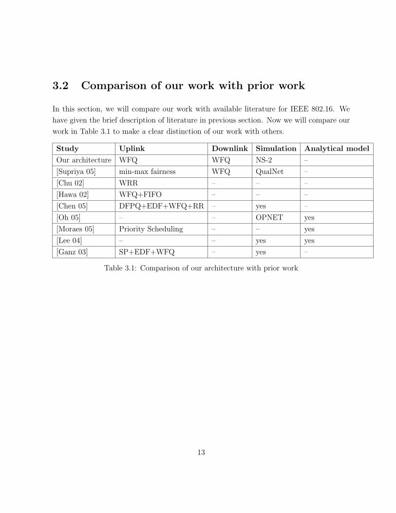
In this section, we will compare our work with available literature for IEEE 802.16. We
have given the brief description of literature in previous section. Now we will compare our
work in Table 3.1 to make a clear distinction of our work with others.
Study Uplink Downlink Simulation Analytical model
Our architecture WFQ WFQ NS-2 –
[Supriya 05] min-max fairness WFQ QualNet –
[Chu 02] WRR – – –
[Hawa 02] WFQ+FIFO – – –
[Chen 05] DFPQ+EDF+WFQ+RR – yes –
[Oh 05] – – OPNET yes
[Moraes 05] Priority Scheduling – – yes
[Lee 04] – – yes yes
[Ganz 03] SP+EDF+WFQ – yes –
Table 3.1: Comparison of our architecture with prior work
13

Chapter 4
Our Scheduling Architecture
4.1 Design Goals
We have designed our scheduling algorithm with the following goals:
• We want to provide delay bound scheduling for real-time traffic (UGS and rtPS flows)
and maximum throughput for data traffic (nrtPS and BE flows).
• We believe that the scheduling algorithm should provide best QoS for all types of
applications. This means the number and types of flow matters to us rather than
number of SSs. So we have designed our scheduling algorithm for the GPC grant
mode and not for the GPSS grant mode.
4.2 Proposed Architecture
4.2.1 Conceptual details
The IEEE 802.16 standard divides the uplink sub-frame into three periods namely ranging
period, bandwidth contention period and data uplink period. We call this the BandWidth
14

Contention (BWC) mode. We also consider a case where we completely remove the band-
width contention period in our architecture and call this the No BandWidth Contention
(NBWC) mode. In NBWC mode, the uplink sub-frame is divided between two parts
only−ranging period and data uplink period. Consequently the total number of data up-
link slots are more in NBWC mode.
We chose WFQ as the scheduling mechanism for uplink and downlink direction because
of mainly two reasons−WFQ provides bit wise bit fareness (according to the assigned
weigths) to all active flows, secondly WFQ also provides flow isolation. As mentioned in
[Miguel 03] that flow isolation is also necessary at the router (BS is an router also) in the
case of unresponsive flows. Our proposed scheduling architecture broadly contains five
parts−WFQ module, BS allocation module, SS uplink module, BS downlink module, and
Classifier module. WFQ module has been used twice in our architecture. One copy of
WFQ module is inside the BS allocation module (for uplink slot allocation) and the other
standalone copy is used for downlink scheduling. The Figure 4.1 shows our IEEE 802.16
scheduling architecture. We will discuss each of these modules in detail below:
WFQ module
This module is responsible for allocating the available bandwidth to different flows in ratio
of their assigned weights. The WFQ scheduling algorithm [Keshav 03] is an approximation
of Generalized Processor Scheduling and needs two things− weights assigned to each flow
and queue length for each flow. The WFQ algorithm calculates the finish time of every
arriving packet and adds this packet in Generalized Processor Sharing (GPS) queue. The
finish time of every packet is a function of its size, weight assigned to its flow, and the
finish time of the last packet in its queue. Packets are dequed from GPS queue in finish
time order (i.e. packet having the earliest finish time will get dequed first).
For WFQ scheduling in uplink direction, each SS has to communicate two things− the
number of packets waiting on its connection(s) and the sizes of the waiting packets. For
UGS, nrtPS and BE flows, the SS has to sends the total number of waiting packets and for
rtPS flows SS has to add sizes of different packets1 also. We call this whole information as
1because variable packet size in rtPS flows
15

queue information which has to be sent to BS. WFQ scheduling in downlink direction is
straight forward as the BS has all queues information and assigned weigths to respective
queues.
Figure 4.1: Our IEEE 802.16 MAC Scheduling Architecture
BS allocation module
This module is responsible for allocating data uplink slots for connections. These slots are
used by an SS to send data in the uplink direction. BS needs to know the queue information
(number of waiting packets and size of each packet) of connections at each SS for WFQ
scheduling. This queue information either piggybacked with data packets or conveyed in
bandwidth contention slots to BS once in each frame. We piggyback queue information
16

with data packets only once in each frame for connections which got data uplink slot(s) in
this uplink sub-frame.
BS uses the WFQ module to enque and deque packets from GPS queue. This WFQ
scheduling (for uplink direction) is completed virtually at the BS, means BS knows queue
information of connections from previous frame and it can virtually simulate GPS enque
and deque processes. For each deque call, BS allocate slots to the corresponding CID (the
CID with which this packet is associated by Classifier module) subjected to the sufficient
number of slots left in uplink sub-frame. We add up all the slots allocated to a single CID
and generate the slots allocation pattern. Once the slot allocation is complete, BS puts
the whole allocation pattern in UL-MAP which is read by each SS on downlink channel
in the beginning of each frame. In BWC mode all SSs send queue information to BS in
bandwidth contention period only (in contention manner) while in NBWC mode, queue
information is piggybacked with data packets only.
With the above specified scheduling, there can be scenarios where one connection never
gets any uplink slots and it is never able to convey its queue information to BS. We call
this case as forever loop. We will suggest a solution for this case in Section 4.2.2.
SS uplink module
Each SS has its different SS uplink module. This module is responsible for informing
SS about ranging contention period (in NBWC mode and both ranging and bandwidth
contention period in BWC mode) and its respective data uplink slots period. This module
is also responsible for ranging, registration, bandwidth Request and connection formation
whenever needed for its SS.
This module reads DL-MAP and UL-MAP at the beginning of each frame for downlink
sub-frame, ranging contention and data uplink duration. No SS is allowed to send data
on uplink channel in downlink sub-frame duration. In ranging period, each SS chooses its
contention window, waits for that many slots then sends Ranging Request (RANG-REQ)
packets to BS. Any SS will keep doing the same in each frame till it gets Ranging Response
(RANG-RSP) from BS. Once any SS got RANG-RSP from BS, it sends Registration
Request (REG-REQ) to BS and waits for the Registration Response (REG-RSP). Once any
SS gets REG-RSP from BS, it is now ready to send connection request with specified flow
17

type to BS. In NBWC mode, our architecture does not have any bandwidth contention
period, so any SS sends the request packets (ranging, registration and connection) in
ranging period only, while in BWC mode the request packets (registration and connection)
are sent in bandwidth contention period. The choice of sending registration and connection
request packets in bandwidth contention period or in ranging contention period does not
really matters in our simulations because SSs can not sent bandwidth request before any
connection formation. So eventually connection formation has to be done before to sent
any bandwidth request packet.
This module is also responsible for sending uplink data packets in appropriate allocated
slots to BS. This module keeps track of which connection(s) of its SS got uplink slots in
UL-MAP. This module start sending data packets to the BS from the corresponding CID
for the specified slots duration. Any SS is not allowed to use more then allotted uplink
slots for any CID. SS piggybacks its remaining queue information of corresponding CID
in last data packet which is used by BS to generate slots allocation pattern for the next
frame.
BS downlink module
This module is responsible for whole downlink scheduling of packets from BS to SSs. BS
uses WFQ module for downlink scheduling of packets. When uplink sub-frame ends, BS
first broadcast DL-MAP and UL-MAP, then RANG-RSP packets, then REG-REP packets,
then CONN-RSP packets then starts sending downlink data packets to SSs. The downlink
channel is always broadcast channel. The weights for different flows in downlink direction
is same as in uplink direction. The WFQ scheduling is not virtual here (as in the case
of BS allocation module) because BS already has all the queue lengths and size of each
downlink packet.
Classifier module
This component is responsible for the association of incoming IP packets with connections.
We are doing this association based on the flow-id of incoming IP packets. Consequently
each SS maintains many MAC level FIFO queues. The number of MAC level queue is same
18

as the connections formed between this SS and BS. Equivalently each connection has its
own MAC level queue maintained at SS side. Incoming packets are queued in respective
MAC level queue after classification.
4.2.2 Other details
Admission Control
Although we have not included any Admission Control mechanism in our implementation
but our choices of number of flows and their weights in the simulations do an admission
control based on remaining bandwidth and minimum reserve bandwidth needed for an
incoming flow.
Forever loop in NBWC mode
In NBWC mode, whenever any connection gets uplink data slots, it appends its queue
information with the last data packet. There might be cases when any connection does not
get any uplink slot(s) in one frame and GPS queue at BS does not have any more packets
of this connection. This scenario will lead us to a case when this connection is not able to
send its queue length to BS ever. We call this case as the forever loop case. To remove
this case, we have implemented the following.
We define a polling within constant time mechanism to solve the forever loop case. At
the very least, each connection should be able to communicate its queue information to BS
within a constant time. We call this constant time as polling time. If any connection is not
able to get its uplink data slots within polling time, BS allocates slots equivalent to at least
one bandwidth packet (used MAC header is BR header in this packet) for this connection.
BS steals these slots from the ranging period duration. This is because ranging happens
very rarely, in-fact only once for each SS in our simulations. Please note that if all the
connections get uplink data slots in each frame, the scheduling will not fall in forever loop
case. Also note the forever loop case applies only to NBWC mode.
19

Choice of polling time
The Polling Time is the maximum duration after which any connection gets unicast
uplink slots to convey its queue information to BS. The duration of these uplink slots
should be such that any connection can send at least one bandwidth request packet to
BS (in our simulations, this duration is 1 slot for UGS, nrtPS and BE flows and 2 slots
for rtPS flows). The choices of number and type of flows decides the appropriate value
of polling time. In our simulations, we have maximum 30 UGS flows, 20 rtPS flows, 10
nrtPS flows and 50 BE flows. We used 2 frame length (20 msec) as our polling time. In
our simulations, we have chosen the weights of different flow types such that we are not
pumping too much traffic from SS to BS. With the choices of weights give in Table 6.1 the
choice of polling time as 2 frames gives satisfactory results.
The choice of polling time is a function of number of flows, type of flows and weights
assigned to different flows. We might want to assign different polling time to different flow
types. Basically the choice of polling time for any flow type is inversely proportional to
weight assigned to this flow type, total number of other flows. Eventually everything will
boil down to the weights assigned to any flow type because we can assign the weights to
any flow type depending on the QoS requirement of this flow type and total number of
other flows.
20

Chapter 5
NS-2 Implementation Details
In this chapter, we will discuss the implementation details of IEEE 802.16 WirelessMAN
standard. We have implemented IEEE 802.16 WirelessMAN standards and WFQ schedul-
ing algorithm in ns2. Our implementation is free and open source and can be downloaded
from URL [nsWL16 06]. We have implemented only IEEE 802.16 MAC CSP layer in ns-2.
We have not focused ourselves on any security issues of IEEE 802.16. We have not imple-
mented IEEE 802.16 PHY layer. We are using the available IEEE 802.11 PHY layer of
ns2 [NS 05].
5.1 IEEE 802.16 Implementation
We have abstracted the relevant part of IEEE 802.16 MAC CSP layer for our implemen-
tation. In particular, the supported features are:
• Interface for IP layer
• TDD frame structure
• GPC mode bandwidth allocation
• RANG-REQ, BW-REQ, and CONN-REQ
21

• RANG-RSP, CONN-RSP
• IEEE 802.16 MAC frame structures
• All four uplink scheduling services
• Packets and CID association based on flowID
5.2 Modified NS Architecture
Network Simulator (ns version 2.29) is a discrete event network simulator. Ns-2 is designed
to simulate all type of traffic and wired and wireless support. The original ns-2 package
comes with IEEE 802.11 Link Layer (LL), MAC and PHY implementation. To the best
of our knowledge, our implementation is the first implementation of IEEE 802.16 on ns-2.
We have implemented IEEE 802.16 on version 2.29 but we believe that that supplied patch
files on [nsWL16 06] will work with other version also.
Ns-2 is an Object Oriented (OO) simulator package. The software structure is divided
into two OO languages C++ and Object TCL (OTCL) to separate the control and packet
level processing. C++ is used for packet level processing while OTCL is used to define
simulation configuration. OTAL and C++ share the class hierarchy. The input simulation
script is has to be written in OTCL with mentioned node topology, type of scheduler,
starting and end time of flows, type of flows with source and destination node ids. More
details on ns-2 can be found from [NS 05].
As shown in Figure 5.1 (the old architecture) a wireless node (or mobile node) in ns-2,
is a collection of address classifier, port classifier, agent, link layer, MAC layer, interface
queue (IFQ) and physical channel. These classifiers distribute in incoming packets to the
corrert agent or outgoing link. The protocol agent represent the application layer and
routing agent represent the IP layer. When packet travels from protocol agent to rout-
ing agent, the routing agent puts the next hop destination in this packet and send this
packet to Link Layer (LL). The LL determines in MAC address of destination hop using
Address Resolution Protocol (ARP). LL puts this MAC address in the packet and forward
this packet to MAC layer. MAC layer determines the time needed to send this packet on
22
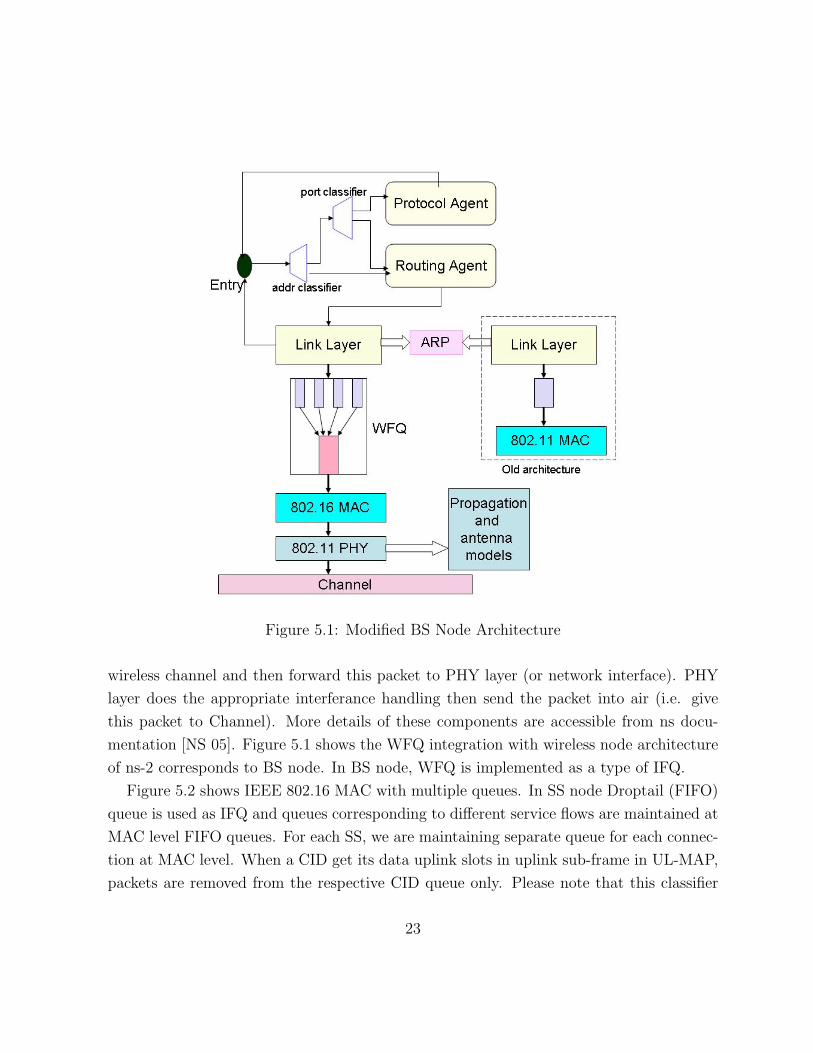
Figure 5.1: Modified BS Node Architecture
wireless channel and then forward this packet to PHY layer (or network interface). PHY
layer does the appropriate interferance handling then send the packet into air (i.e. give
this packet to Channel). More details of these components are accessible from ns docu-
mentation [NS 05]. Figure 5.1 shows the WFQ integration with wireless node architecture
of ns-2 corresponds to BS node. In BS node, WFQ is implemented as a type of IFQ.
Figure 5.2 shows IEEE 802.16 MAC with multiple queues. In SS node Droptail (FIFO)
queue is used as IFQ and queues corresponding to different service flows are maintained at
MAC level FIFO queues. For each SS, we are maintaining separate queue for each connec-
tion at MAC level. When a CID get its data uplink slots in uplink sub-frame in UL-MAP,
packets are removed from the respective CID queue only. Please note that this classifier
23

component is nowhere related to classifier component defined in Section 4.2 in Figure 5.1.
Figure 5.2: Modified SS Node Architecture
We first patched our ns2 (version 2.29) with wired WFQ implementation from [WWFQ 05].
We modified the appropriate files to make this WFQ module working in wireless scenario.
Our IEEE 802.16 MAC implementation sits parallel with IEEE 802.11 MAC implemen-
tation in ns2 directory architecture as shown in Figure 5.3. In the context of functional
specifications, our implementation follows the ns2 conventions of IEEE 802.11. We have
designed and implemented the functions with same naming convention as IEEE 802.11
whenever possible. Our function specifications and each function detail are included with
package and can be downloaded from the URL [nsWL16 06].
Figure 5.3: Location of IEEE 802.16 MAC in NS2.29
24

Chapter 6
Simulation Analysis
We have used Network Simulator (ns version 2.29) as our simulation platform. We have
performed extensive simulations in both uplink and downlink directions to show the effec-
tiveness of WFQ scheduling algorithm. More specifically we want to evaluate the following
in our architecture:
• Effect of one type of flow on other type of flow. That is keeping a constant number
of one type of flow, evaluate the average performance degradation (delay for UGS
and rtPS flows and throughput for nrtPS and BE flows) of this type of flow with the
increment in the number of other type of flow.
• Choice of appropriate bandwidth contention period in BWC mode with a constant
number of flows of same flow classes.
• Performance comparison of BWC and NBWC mode with above choice as bandwidth
contention duration in BWC mode.
6.1 Assumptions
We have assumed certain things in our implementation of IEEE 802.16 standard in open
source ns-2 simulator [NS 05]. We will state our assumptions and their justification in
25

respective context. We have assumed the following:
• We are implementing only IEEE 802.16 MAC CPS layer, consequently we are not
implementing any security mechanism used by IEEE 802.16 MAC Privacy sublayer.
• BS does not broadcast any Downlink Channel Descriptor (DCD) and Uplink Channel
Descriptor (UCD) because all nodes are use only one downlink and uplink channel
for communication.
• Time synchronization is not really a problem in simulations, so we are not using any
time stamp in any packets. We are not using any guard time also for the same reason.
• Our scheduling algorithm does not employ any admission control because we are not
focusing on the same in this study. However our choices of number and types of flows
are such that we do not need any admission control mechanism. We will elaborate
more on this point in Section 4.2.2.
• All nodes (BS and SSs) use omni-directional antenna with available IEEE 802.11
PHY layer of ns-2 [NS 05] for communication, consequently we are not implementing
IEEE 802.16 PHY layer.
• We have not implemented any Automatic Repeat reQuest (ARQ) mechanism of IEEE
802.16, that is we are assuming no packet losses on air.
We have used the following specifications to map different flows classes:
UGS Constant Bit Rate (CBR) traffic is used for UGS flow. We have used the specifica-
tions of G.729 (8Kbps) codec from [Cisco 00]. According to G.729 default specifica-
tions our CBR packet size is 28 Bytes with 22.4 Kbps constant rate.
rtPS We have used the video traces to generate rtPS flows from [Trace 00]. We have
performed our simulations on target 64 Kbps with H.263 codec video trace from
[Video 00]. Our implementation supports all other target bit rate specified on [Trace 00]
with MPEG-4 codec.
26

nrtPS We have used ns-2 FTP traffic on top of TCP to generate nrtPS flows. The packet
size of FTP flow is constant and equal to 1000 Bytes.
BE We have used ns-2 telnet traffic to generate BE flow. NS-2 uses 1000 Bytes (constant
size) packets for telnet flow. This modeling of telnet flow is not appropriate. We will
comment on how our simulation graphs will change in the case of appropriate telnet
flow later in this chapter.
Based on the above flow specifications, we have to send sizes of packets only for rtPS flows
(other flows have constant size packets) as queue information.
We have simulated WFQ scheduling efficiency in two cases−with Bandwidth Contention
(BWC) and No Bandwidth Contention (NBWC) period. In BWC mode, each SS sends its
every connection queue information to BS in Bandwidth Contention Period (in contention
manner). While in NBWC mode, whenever any connection gets uplink data slots, it
appends its queue information with the last data packet.
The NBWC mode seems to generate some overhead because of piggybacking of extra
bytes in last data packet but our simulation results shows that throughput achieved in
NBWC is more than BWC mode. Moreover, extra piggybacked bytes is 1 (for UGS, nrtPS
and BE flows) and 21 bytes1 (assuming maximum 10 packets waiting). It is easy to check
that adding 1 byte in UGS (or nrtPS and BE flows) does not cost much extra in terms of
slots(or integral number of slots) needed to send the packet but number of slots needed is
changed whenever we send extra 21 bytes. Please note that, piggybacking is done only once
in each frame for connections which got uplink slots in the uplink sub-frame, so overhead
caused due to rtPS flows are more. This effect clearly comes in our simulation graphs also.
Our choices of weights for different types of traffic is directly proportional to their
minimum reserved bandwidth. When any SS sends connection request to BS, it specifies
the minimum reserved bandwidth (and more parameters) for this connection. If the BS is
granting bandwidth to this connection then the BS uses the specified minimum reserved
bandwidth as weight for this connection. In our simulations, we have used the following
weights: The UGS and rtPS flows has 22.4 Kbps and 64.0 Kbps as average bandwidth
12 Bytes to send the size of each 10 packet and 1 Byte for the total number of packets, thus total20+1=21 Bytes
27

Flow type Weight
UGS 22.4
rtPS 64.0
nrtPS 100.0
BE 10.0
Table 6.1: Weights for different flow type
respectively. The weights for nrtPS and BE traffic are taken in such way that, with a
given number of nrtPS and BE flows, the maximum available part of whole bandwidth
should not acquired by these flows only. In this manner, we are giving preference to UGS
and rtPS flows with the proper choices of weights and number of flows. The length of
polling time (refer to Section 4.2.2) is 2 frame length (=20 msec). Running time for our all
the simulations is 20 sec. For all our simulations, the calculated delay is application level
(or agent level in ns2 terms) one way delay and then averaged over the number of flows.
Similarly the calculated throughput is application level throughput i.e. number of bytes
sent any application (or agent) within the simulation period.
6.2 Uplink Flow Analysis
In this section, we will present our simulation analysis for Uplink flows. We have focused
ourselves on two things− delay boundedness (for UGS and rtPS) and maximum achievable
throughput (for nrtPS flows). Our choices of the number and type of flows shows the effect
of one type of flow on the other type of flow. We have performed the simulations in both
BWC and NBWC mode.
Our simulation parameters and calculated parameters for uplink flow are as follows:
6.2.1 Comment on parameters choices
Data Rate The default used data rate is 11Mbps. It is same as the maximum data rate
in IEEE 802.11b standard. The higher data rate may affect our simulations in the
28

Parameters Value
Data Rate 11Mbps
Basic Rate 1Mbps
Slot Time 8 micro sec
Frame Length 10 msec
Downlink Frame 2 msec
Uplink Frame 8 msec
Ranging period 100 slots (=0.8 msec)
Bandwidth Contention 100 slots (=0.8 msec)
Data Uplink Slots (BWC) 800 slots (=6.4 msec)
Data Uplink Slots (NBWC) 900 slots (=7.2 msec)
Table 6.2: Simulation parameters for uplink flow analysis
context of 802.11 PHY implementation of ns-2. It might be possible BS and SS not
able to communicate at higher data rate. On the other hand, we will send data
packets in fewer number of slots on higher data rates. We chose 11Mbps because we
are using of IEEE 802.11 PHY channel for data communication.
Basic Rate Basic rate is used only to send MAC management packets of IEEE 802.16.
Any other choice of basic rate will not affect our simulation because basic rate is not
used for any data communication.
Slot time We use slot time as 8 micro seconds. Any larger value of slot time will waste the
bandwidth because the slots are always allocated in integral number. The lower value
of slot time will affect the UL-MAP structure, because more number of slots will be
needed to send the same amount of data. The lower value of slot time will increase
the byte space needed to broadcast the UL-MAP (or the time needed to broadcast
UL-MAP). The value 8 micro second is appropriate in both respects above.
Frame Length A large value of frame length will increase the delay of UGS and rtPS
flows, besides it may also conflict with TCP timeout (in nrtPS flows). In TCP
timeout case, TCP layer will keep sending the same packet again and again. A lower
29

value of frame length will be wastage of bandwidth because each frame has ranging
contention period and ranging is performed very rarely. Thus keeping a lower value
of frame length will lead us to waste bandwidth in ranging contention period.
Uplink Frame When we study uplink flow analysis, all the running flows are in uplink
direction so we kept the value of uplink frame higher then downlink frame. Moreover
there are no downlink flows in the case of UGS and rtPS flow and only ACK (40
Bytes) packets for nrtPS and BE flows, so keeping a low value of downlink flow make
sense for uplink flow analysis.
The above explanation also explains the value of downlink frame.
Ranging Period Connection formation is done only in ranging period (in NBWC mode).
In our simulations, we have up to 50 parallel connections. The probability of sending
requests packets on same time for two (or more SS) is very less. We have taken 100
slots as ranging period for simulation setup. A fewer or lerger number of slots will
not affet our simulation analysis.
Contention Period Our choices of number and type of flow decides the number of slots
needed for bandwidth contention period in BWC mode. We will elaborate more on
how to choose a good contention period in Section 6.2.5.
Data Uplink Slots The remaining slots from uplink frame after deducting ranging and
bandwidth contention period (in BWC mode) or simply ranging period (in NBWC
mode) is used for data uplink slots.
We have calculated the few more parameters for uplink flow analysis
Total frame length = 10 ms and Data rate = 11Mbps
Data uplink period (BWC mode) = 6.4 ms
Expected MAC layer throughput (BWC mode) = (6.4/10)*11 = 7.04 Mbps
Data uplink period (NBWC mode) = 7.2 ms
Expected MAC layer throughput (NBWC mode) = (7.2/10)*11 = 7.92 Mbps
MAC level size of one UGS packet2 = (28+10) = 38 Bytes
228 Bytes UGS packet size and 10 Bytes extra header size
30

slots for one UGS packet = (38/11) = 3.45 slots (4 integral slots)
MAC level size of one nrtPS packet3 = (1040+10) = 1050 Bytes
slots for one nrtPS packet = (1050/11) = 95.45 slots (96 integral slots)
Calculated parameters Value
Expected MAC layer Throughput (BWC) 7.04 Mbps
Expected MAC layer Throughput (NBWC) 7.92 Mbps
slots for single UGS packet 4 slots
slots for single nrtPS packet 96 slots
slots for single BE packet 96 slots
Table 6.3: Calculated parameters for uplink flow analysis
6.2.2 Delay Analysis for Uplink Flows
We have simulated the effect of increments in the number of one type of flow on the constant
number of other type of flow both in BWC and NBWC modes.
Effect of BE increment on 30 UGS flows We have simulated 30 UGS flows with in-
creasing number of BE flows. The number of BE flows are ranging from 0 to 20.
Figure 6.1 shows the delay analysis of 30 UGS flows with increment in BE flows. BE
flow packets come very rarely so the UGS delay is constant. In BWC mode very less
BE connections have any packets waiting at SS, so maximum number BE connec-
tions do not take part in contention period to send bandwidth request packets and
subsequently most of UGS flows are able to send their queue lengths to BS.
In NBWC mode, all the UGS flows are able to get uplink data slots and send their
queue information to BS, thus the delay is almost constant and is equal to 9 msec.
Effect of nrtPS increment on 30 UGS flows In Figure 6.2 we have simulated 30 UGS
flows with increment in the number of nrtPS flows. The number of nrtPS flows are
ranging from 0 to 20. Due to the contention in BWC mode, UGS flows are not
31040 Bytes nrtPS packet size and 10 Bytes extra header size
31

Figure 6.1: Average UGS delay with BE flows
able to send their queue information to BS. Consequently the GPS queue at BS is
relatively empty for UGS flows (equivalent to non-active queue), so WFQ scheduling
give remaining slots to active queues (rtPS flows). Thus UGS delay increment is
linear with nrtPS flows.
In NBWC mode, UGS flows are able to send its queue length on appropriate time,
so the delay is bounded (ranging from 8 msec to 15 msec). Moreover the GPS queue
is not relatively empty because the piggybacking is done with data packets.
Effect of rtPS increment on 30 UGS flows In Figure 6.3, we have simulated 30 UGS
flows with increasing number of rtPS flows. The number of rtPS flows are ranging
from 0 to 20. In BWC mode, (after 12 rtPS flows) when the number of rtPS flows
increases, the average UGS delay also increases. In BWC mode, all the connections
are not able to send their queue length to the BS in due to contention. It can be easily
seen that the offered load on network is very less (22.4*30+64*20=672+1280=1952
32

Figure 6.2: Average UGS delay with nrtPS flows
Kbps) as compared to available bandwidth but delay of UGS flows keeps increasing.
In NBWC mode, each connection is able to send its queue length piggybacked with
last data packets, so delay of UGS flows are bounded (9 msec).
Effect of BE increment on 20 rtPS flows We have simulated 20 rtPS flows with the
increment in number of BE flows. Figure 6.4 shows the delay graph of 20 rtPS
flows with the increment in BE flow and explains the random behavior of rtPS flows
itself. As shown in Figure 6.1 the BE flows does not pump much data on network
(because UGS delay is almost constant in BWC mode also), the delay of 20 rtPS
flows is unpredictable but lies in a certain range (55msec to 90 msec). The rtPS
delay is unpredictable because of its variable sized data packets. Because of variable
data sized packets, we need to send queue length as well as the packets sizes to BS
for WFQ scheduling. Sending this whole information takes more number of slots,
consequently only few number (ranging from 7 to 12) of connection are able to send
33

Figure 6.3: Average UGS delay with rtPS flows
queue information to BS in each contention period. Moreover 64 Kbps is the average
data rate for rtPS flows, but this data rate varies from 51 Kbps to 72Kbps.
In NBWC mode, because the offered load is very less, all the rtPS flows are able to
send their queue information and hence the rtPS delay is less and bounded (between
11msec to 12msec).
Effect of nrtPS increment on 20 rtPS flows In Figure 6.5 we have simulated 20 rtPS
flows with increasing number of nrtPS flows. The number of nrtPS flows are ranging
from 0 to 20. In BWC mode the initial jump in delay (80 msec) is because of
contention period and collision at BS. Moreover rtPS flows needs more slots to send
their queue information to BS (because of appending packets size also). In BWC
mode, the contention period is less to send queue length of 20 rtPS flows. The rtPS
delay is more with nrtPS flows as compared Figure 6.2. The reasons given for UGS
delay with nrtPS flows also apply here.
34

Figure 6.4: Average rtPS delay with BE flows
In NBWC mode, the delay of rtPS flows also increases (from 11 msec to 38 msec).
This is because the rtPS flow pump less data then nrtPS flows. Consequently the
rtPS queue becomes non-active with respect to nrtPS queue for GPS scheduling at
BS. Eventually polling within constant time mechanism will allow the rtPS flows to
send their queue length to BS.
Effect of UGS increment on 20 rtPS flows The Figure 6.6 shows the delay variation
of 20 rtPS flows with increment in number of UGS flows. In BWC mode, due to
contention period and collision at BS, rtPS connections are not able to send queue
length to BS even if the offered load is very less compared to the available bandwidth.
This results in more variation in delay.
In NBWC mode, the rtPS delay is almost constant and bounded by 13 msec.
35

Figure 6.5: Average rtPS delay with nrtPS flows
The reasons given for rtPS unpredictable behavior for Figure 6.4 also explain the unpre-
dictable behavior of rtPS flows in Figure 6.6 and Figure 6.5. In any case, the increment
in number of other types of flows will increase the rtPS delay and this behavior is clearly
present in all Figures 6.6, 6.5 and 6.4.
6.2.3 Throughput Analysis for Uplink Flows
We have also calculated the effect of UGS, rtPS and BE flows on the throughput perfor-
mance of nrtPS flows through simulations in both BWC and NBWC mode. In this set of
simulations, we have 10 nrtPS flows and vary the other number of flows from 0 to 20. The
calculated throughput here is application level throughput i.e. the number of bytes sent
by application divided by total simulation time. The throughput graph of 10 rtPS flows
with variable number of other flows is presented in Figure 6.7. In the case of UGS flows,
36
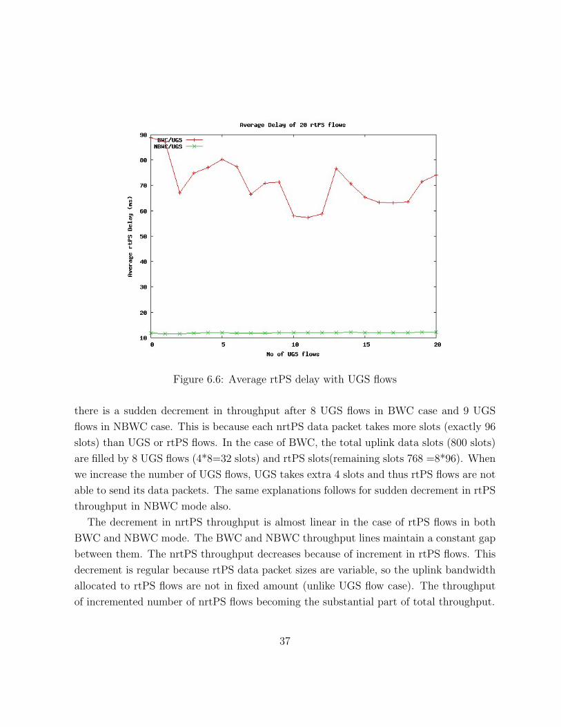
Figure 6.6: Average rtPS delay with UGS flows
there is a sudden decrement in throughput after 8 UGS flows in BWC case and 9 UGS
flows in NBWC case. This is because each nrtPS data packet takes more slots (exactly 96
slots) than UGS or rtPS flows. In the case of BWC, the total uplink data slots (800 slots)
are filled by 8 UGS flows (4*8=32 slots) and rtPS slots(remaining slots 768 =8*96). When
we increase the number of UGS flows, UGS takes extra 4 slots and thus rtPS flows are not
able to send its data packets. The same explanations follows for sudden decrement in rtPS
throughput in NBWC mode also.
The decrement in nrtPS throughput is almost linear in the case of rtPS flows in both
BWC and NBWC mode. The BWC and NBWC throughput lines maintain a constant gap
between them. The nrtPS throughput decreases because of increment in rtPS flows. This
decrement is regular because rtPS data packet sizes are variable, so the uplink bandwidth
allocated to rtPS flows are not in fixed amount (unlike UGS flow case). The throughput
of incremented number of nrtPS flows becoming the substantial part of total throughput.
37

Figure 6.7: Throughput of nrtPS flows
The decrement in nrtPS throughput is very almost linear in the case of BE flows also.
The above explanation applies here also. The decrement in nrtPS throughput is very less
(170 Kbps in both BWC and NBWC mode).
6.2.4 Total Throughput in BWC and NBWC
We have also calculated the total throughput for the scenario specified in Section 6.2.2 and
6.2.3 in both BWC and NBWC modes.
Total Throughput with 30 UGS flows Figure 6.8 shows the total throughput graph
of 30 UGS flows with variable number of other flows. The graphs of Figure 6.8 for
BWC/BE and NBWC/BE almost overlap. The graphs of BWC/rtPS and NBWC/rtPS
also almost overlap. This clearly shows that NBWC mode perform equivalent to
38

Figure 6.8: Total throughput with 30 UGS flows
BWC mode rtPS and BE flows for total throughput case. In the case of nrtPS flows,
the achieved throughput is more in NBWC mode because of extra data uplink slots.
Total Throughput with 20 rtPS flows Figure 6.9 shows the total throughput graph
of 20 rtPS flows with variable number of other flows. The graphs of Figure 6.9 for
BWC/BE and NBWC/BE almost overlap. The graphs of BWC/UGS and NBWC/UGS
also almost overlap. This shows that NBWC mode perform equivalent to BWC mode
UGS and BE flows for total throughput case. In the case of nrtPS flows, the achieved
throughput is more in NBWC mode because of extra data uplink slots. The behav-
ior is same as Figure 6.9 for the case of 30 UGS flows with variable number of other
flows.
Total Throughput with 10 nrtPS flows The analysis of total throughput with 10 nrtPS
39
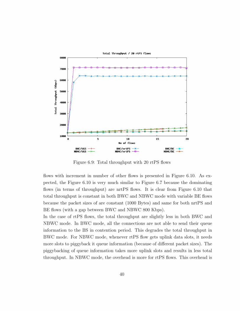
Figure 6.9: Total throughput with 20 rtPS flows
flows with increment in number of other flows is presented in Figure 6.10. As ex-
pected, the Figure 6.10 is very much similar to Figure 6.7 because the dominating
flows (in terms of throughput) are nrtPS flows. It is clear from Figure 6.10 that
total throughput is constant in both BWC and NBWC mode with variable BE flows
because the packet sizes of are constant (1000 Bytes) and same for both nrtPS and
BE flows (with a gap between BWC and NBWC 800 Kbps).
In the case of rtPS flows, the total throughput are slightly less in both BWC and
NBWC mode. In BWC mode, all the connections are not able to send their queue
information to the BS in contention period. This degrades the total throughput in
BWC mode. For NBWC mode, whenever rtPS flow gets uplink data slots, it needs
more slots to piggyback it queue information (because of different packet sizes). The
piggybacking of queue information takes more uplink slots and results in less total
throughput. In NBWC mode, the overhead is more for rtPS flows. This overhead is
40

Figure 6.10: Total throughput with 10 nrtPS flows
not very high and total throughput is more in NBWC mode.
In the case of UGS flows, the total throughput increases till 8 UGS flow (in BWC
mode) and 9 UGS flows (for NBWC mode). This is because the unused slots by
rtPS flows is used by UGS flows. Further increment in number of UGS flows results
in decrement in total throughput because now UGS is taking some uplink slots and
rtPS flows not able to get slots (minimum 96 to send one rtPS packet). The same
feature again come with 16 UGS flows. The decrement in total throughput is less
with 16 UGS flows because now UGS flows are also contributing in total throughput.
Further increment in UGS flows will decrease the total throughput again.
In all the case above, the total throughput in NBWC mode is higher then BWC mode.
This explains that NBWC mode throughput is always higher than BWC mode.
41

6.2.5 Bandwidth Contention Period Analysis
IEEE 802.16 standard does not specify the bandwidth contention duration. All the simu-
lations in Section 6.2.2 and Section 6.2.3 have been performed with bandwidth contention
period equal to 100 slots(=0.8 msec). We have performed simulations to justify our choice
of 100 slots as contention period. The choices of number and type of flows gives a clear
idea to choose a proper contention period length.
Figure 6.11: Average UGS delay with bandwidth contention period
We have simulated a number of UGS flows to evaluate the optimal value of contention
period for BWC mode. The Figure 6.11 shows the delay analysis of only UGS flows with
variable number of slots for the contention period. For a very less number of slots, the
UGS delay is high because all the UGS flows are not able to send their queue information
in bandwidth contention period. The UGS delay come to a minimum value for a particular
number of slots (this value depends on simulated number of UGS flows). We call this
42

contention period as suitable contention period at which the delay is minimum for a given
number of UGS flows in BWC mode. Beyond the suitable contention period the UGS delay
starts increasing almost linearly because of the length of contention period is more than
required and this further delays the UGS packets.
With 30 UGS flows, the delay is minimum at 100 slots as contention period. This shows
that for 30 UGS flows we should take 100 slots as contention period in BWC mode. Sim-
ilarly if we want to compare the performance of BWC and NBWC with 20 UGS flows or
40 UGS flows, we should take 60 or 120 slots as contention period duration respectively.
Figure 6.12: Average rtPS delay with bandwidth contention period
Similarly the Figure 6.12 shows the delay analysis of only rtPS flows with variable num-
ber of slots for contention period. The Figure 6.12 also shows that the delay of rtPS flows
becomes almost constant. This behavior is different from Figure 6.11. In the case of UGS
flows, all the UGS flows are able to send their queue information at their respective suitable
contention duration. Increasing the contention period length further increase end to end
43
delay of UGS flows. In the case of rtPS flows, one factor to increase the delay is increment
in bandwidth contention period (same as UGS flows) the second factor to decrease the
delay that all rtPS flows are able to send their queue information with larger bandwidth
contention time. The delay of rtPS flows is almost constant so the choice of number of
slots for contention period is open to us. We used 100 slots as this value give us minimum
delay for UGS flows in BWC mode.
6.2.6 Comparison between BWC and NBWC modes
We have simulated a number of uplink flows in both BWC and NBWC mode in previous
sections. We have evaluated the effect of increment in the number of one type of flow on
another type of flow. We have the following conclusions from the simulations of uplink
flows:
• The average delay of constant number of UGS flows is almost constant with the
increment in number of BE flows in both BWC and NBWC mode. However the
value of delay is higher in BWC mode.
• The average delay of constant number of UGS flows is linearly increasing with the
increment in number of nrtPS flows in both BWC and NBWC mode. However the
slope is negligible in NBWC mode compared with BWC mode.
• In BWC mode the average delay of constant number of UGS flows is almost constant
up to a certain increment in rtPS flows. Further increment in rtPS flows increments
the average delay in linear manner. In NBWC mode, the average delay is almost
constant for a large number of rtPS flows.
• The average delay of constant number of rtPS flows is unpredictable (but lies in a
certain range) with the increment of UGS or BE flows in BWC mode while it is
almost constant in NBWC mode. With the increment of nrtPS flows the average
rtPS delay increases linearly in both BWC and NBWC mode. Again the slope of
BWC mode is much higher then NBWC mode.
44

• Throughput of nrtPS flows decreases linearly with the increment in rtPS or BE flows
in both BWC and NBWC mode. nrtPS throughput decreases suddenly then stabilizes
itself with increment in UGS flows in both BWC and NBWC mode.
• In all above cases, NBWC mode performs equivalent or better than BWC mode in
terms of delay for UGS and rtPS flows as well as in terms of throughput for nrtPS
flows with a proper choice of polling time.
• The total throughput is almost constant with constant number of nrtPS flows and
varying number of BE flows in both BWC and NBWC mode. Total throughput
lies in a certain range with constant number of nrtPS flows and varying number of
rtPS flows. Total throughput suddenly decreases then stabilizes itself with constant
number of nrtPS flows and varying number of UGS flows.
• The total throughput behavior is similar to the throughput behavior of nrtPS flows
because the dominating flows (in terms of throughput) are nrtPS flows in both BWC
and NBWC mode.
• The optimal number of slots for bandwidth contention period for BWC mode depends
upon the choices of number and type of flows. We use 100 slots for bandwidth
contention period for our choices of flows.
6.3 Downlink Flow Analysis
We have simulated a number of downlink flows in a separate series of simulations. The
focused metrics for downlink flows are also same as uplink flows (i.e. delay boundedness for
UGS and rtPS flows and maximum achievable throughput for nrtPS flows). Consequently
the number and type of downlink flows are same as uplink flows as given in Section 6.2.
We have also evaluated the the effect of one type of flow on other type of flow. Please not
that we have simulated uplink or downlink flows one at a time (ofcourse there are ACK
packets in opposite direction with very less size and that too only with nrtPS and BE
flows). Consequently while simulating donwlink flows, having BWC or NBWC modes in
45

uplink direction does not affect our simulation analysis because the data uplink period is
sufficiently large for all ACK packets. We have performed the simulations with BWC mode
in uplink direction. Our simulation parameters and calculated parameters are as follows
for downlink flows:
Parameters Value
Data Rate 11Mbps
Basic Rate 1Mbps
Slot Time 8 micro sec
Frame Length 10 msec
Downlink Frame 8 msec
Uplink Frame 2 msec
Ranging period 25 slots (=0.2 msec)
Bandwidth Contention 25 slots (=0.2 msec)
Data Uplink Slots 200 slots (=1.6 msec)
Number of Downlink Slots 1000 slots (=8.0 msec)
Table 6.4: Simulation parameters for downlink flow analysis
We have calculated the few more parameters for downlink flow analysis
Total frame length = 10 ms and Data rate = 11Mbps
Downlink period = 8.0 ms
Expected MAC layer downlink throughput = (8.0/10)*11 = 8.8 Mbps
Data uplink period in uplink direction = 1.6 ms
Expected MAC layer uplink throughput = (1.6/10)*11 = 1.76 Mbps
MAC level size of one UGS packet4 = (28+10) = 38 Bytes
slots for one UGS packet = (38/11) = 3.45 slots (4 integral slots)
MAC level size of one nrtPS packet5 = (1040+10) = 1050 Bytes
slots for one nrtPS packet = (1050/11) = 95.45 slots (96 integral slots)
MAC level size for one ACK packets = (40+10) = 50 Bytes
slots for one ACK packets = (50/11) = 4.54 slots (5 integral slots)
428 Bytes UGS packet size and 10 Bytes extra header size51040 Bytes nrtPS packet size and 10 Bytes extra header size
46

Calculated parameters Value
Expected MAC layer downlink throughput 8.8 Mbps
Expected MAC layer uplink throughput 1.76 Mbps
slots for single UGS packet 4 slots
slots for single nrtPS packet 96 slots
slots for single BE packet 96 slots
slots for single ACK packet 5 slots
Table 6.5: Calculated parameters for downlink flow analysis
6.3.1 Delay and Throughput Analysis for Downlink Flows
We have simulated the effect of increment in the number of one type of flow on the constant
number of other type of flow in downlink direction.
Figure 6.13: Average UGS delay with other flows
47

Effect on 30 UGS flows Figure 6.13 shows delay variation of 30 UGS flows with in-
creasing number of other types of flows. The delay of UGS flows is almost constant
with the increment in number of rtPS or BE flows. The delay of UGS flows is less
with the increment in nrtPS flows. This gap is very less (< 2.5 ms). Overall the
delay of 30 UGS is bounded by 5.5 msec.
Figure 6.14: Average rtPS delay with other flows
Effect on 20 rtPS flows The Figure 6.14 shows the delay analysis of 20 rtPS flows with
the increment in number of other flows. As we alredy explined that the behavior of
rtPS flows is unpredictable (but lies in a certain range in Figure 6.4 and 6.6), here
also the delay of rtPS flows are unpredictable (for UGS and BE flows). The delay of
rtPS flows is less with the increment of nrtPS flows and almost constant. Again this
gap is very less (< 3.5 msec). In all cases the rtPS delay is bounded by 9 msec.
Effect on 10 nrtPS flows Figure 6.15 represent the throughput analysis of 10 rtPS flows
48

Figure 6.15: nrtPS throughput with other flows
with variable number of other flows. The decrement in throughput of rtPS flows is
linear in the case of BE and (with higher slope for rtPS flows). The throughput of
nrtPS flows decreases suddenly then become constant in the case of UGS flows. The
behavior is because of UGS flows are taking those slots which were allocated to nrtPS
flows. Figure 6.15 is very much similar to uplink nrtPS throughput analysis graphs
presented in Figure 6.7.
6.3.2 Conclusions from Downlink Simulations
We have simulated a number of flows in downlink direction to evaluate the performance of
our architecture. We can conclude the following from downlink simulations:
• The average delay of constant number of UGS flows is bounded by constant number
with the increasing number of rtPS, nrtPS or BE flows.
49

• The average delay of constant number of rtPS delay is also bounded by constant
number with the increasing number of UGS, nrtPS or BE flows.
• The throughput of constant number of nrtPS flows decreases linearly with increasing
number of rtPS or BE flows (the slope is higher for rtPS flows). With increasing
number of UGS flows, the throughput decreases suddenly then it stabilizes itself.
• The Figure 6.13 is not the expected delay variation. May be because the value of the
delay is very low (5 msec). The same thing applies to Figure 6.14 also.
50

Chapter 7
Conclusions and Future Work
7.1 Conclusions
In this thesis we presented a scheduling architecture for IEEE 802.16 standard. Our
scheduling architecture usea WFQ as the downlink as well as the uplink scheduling al-
gorithm. Downlink scheduling is easy because only involve entity is BS and it has all the
required information for the same. For uplink scheduling, each SS has to send its queue
information to BS. As defined in the standard, SSs can send their bandwidth request to
BS either in bandwidth contention period or in unicast slots which is allocated to SSs in
each frame or through piggyback the connections demands with data packets.
In the NBWC mode of operation, we completely remove bandwidth contention period
and send bandwidth request piggybacked with data packets thus we are removing any
possibility of collisions at BS. Our architecture has forever loop drawback as defined in
Chapter 6. We propose polling time concept to remove this drawback. We also suggest
a intutive way to choose polling time depending upon number and types of flows in Sec-
tion 4.2.2.
Our simulation results shows that NBWC mode performs better in terms of delay for
real time traffic and in terms of through for high data rate traffic in both uplink and down-
link direction. We chose a very simple approach to design our architecture and showed
that this architecture indeed statisfy the QoS requirements of different application flows.
51

The simplicity lies in our sheduling algorithm (WFQ) also which is known from last 2
decads and is able to perfom satisfactory for newly designed IEEE 802.16 architecture.
Besides this, the developers do not need to bother about the two different scheduling algo-
rithm for uplink and downlink direction. In the performance analysis to NBWC mode, we
have shown that it is possible to omit the bandwidth contention period from IEEE 802.16
standards.
7.2 Future Work
Our work can be extended in many dimensions. We will propose here some questions which
are still unanswered in our study:
Polling time calculation We have given an idea to calculate polling time in Section 4.2.2.
This idea includes some proportional relations with flow weight, number and type of
flows running and other factor. One has to explore this further into it and can setup
a concrete formula for polling time calculation. Please note that polling time can be
different for different flow type (in-fact it can different for different flows also).
ARQ mechanism The IEEE 802.16 standard mentioned some MAC ARQ mechanism.
Our work can also be extended to implement any suitable ARQ mechanism in ns-2.
This ARQ mechanism should also take care of the collisions at BS (in BWC mode)
and packet losses (in both BWC and NBWC mode).
Frame Size Other researchers have proposed dynamic adjustment of the frame size. One
parallel extension of ns-2 with dynamic frame size for IEEE 802.16 can be found
from [AN 06] and related BTech project report [BTP 06] will be a good help to
formulate the size of frame (or the sizes of uplink sub-frame and downlink sub-frame)
dynamically.
Fragmentation The IEEE 802.16 standard suggest some fragmentation scheme also.
These fragmentation scheme use fragmentation specific headers. We have not im-
plemented any fragmentation scheme. One can extend our work in this direction
also.
52

Order of bandwidth contention period The IEEE 802.16 standard puts the band-
width contention period in the middle of ranging contention period and data uplink
period. The authors in [Moraes 05] suggest a new way to change contention period
into unicast slots and change the order of contention period (i.e. put the contention
period after data uplink slots). In BWC mode, one can extend our work in this
direction also.
Classification of packets The IEEE 802.16 standard lacks in packet classification at
MAC level, means how to associate packets to connection. A wrong association of
packets will degrade the desired QoS very drastically. In our current design we are
associating packets with connection based on their flowID. In real scenario, flowID
is not defined for any packets. You can extract source and destination IP addresses
from packet. One has to explore more on how to extract application specific infor-
mation from the packet at MAC level for correct association between packets and
connections.
HTTP traffic as BE flows We have mapped the BE flows to ns-2 default telnet appli-
cation traffic. HTTP traffic can also map to BE flows. PackMime [Pack 06] is an
extension of ns-2 which include persistent (http 1.1) and non-persistent (http 1.0)
traffic generator. One can simulate PackMime HTTP traffic as BE flows to test our
architecture performance in more detail. PackMime will be shipped with the default
ns-2 package from the next version.
53

Bibliography
[nsWL16 06] http://www.cse.iitk.ac.in/users/braman/students/2006/abhim/index.html
[Draft 04] IEEE 802.16, IEEE Standard for Local and Metropolitan Area Networks
- Part 16: Air Interface for Fixed Broadband Wireless Access Systems,
IEEE Std. 802.16, Oct. 2004.
[WLMAN 06] IEEE 802.16 Working Group on Broadband Wireless Access.
http://wirelessman.org
[Supriya 05] Supriya Maheshwari, “An Efficient QoS Scheduling Architecture for
IEEE 802.16 Wireless MANs,” Masters Thesis, IIT Bombay, 2005.
[Chu 02] Guosong Chu, Deng Wang, and Shunliang Mei. “A QoS architecture for
the MAC Protocol of IEEE 802.16 BWA System.” IEEE International
Conference on Communications Circuits and System and West Sino Ex-
positions, vol.1, pp.435–439, China, 2002.
[Parekh 93] Parekh, A. K. and Gallager, “A generalized processor sharing ap-
proach to flow control in integrated services networks: the single-
node case.” IEEE/ACM Trans. Netw. 1, 3 (Jun. 1993), 344-357. DOI=
http://dx.doi.org/10.1109/90.234856
[Hawa 02] M. Hawa and D. W. Petr, “Quality of service scheduling in cable and
broadband wireless access systems,” 10th IEEE International Workshop
on Quality of Service, May 2002, pp. 247–255.
54

[DOCSIS 00] “Data-Over-Cable Service Interface Specifications Radio Frequency In-
terface Specification,” MCNS Consortium, CableLabs, SP-RFIv1.1106-
001 215, 2000.
[Chen 05] Jianfeng Chen, Wenhua Jiao, Qian Guo, “Providing integrated QoS con-
trol for IEEE 802.16 broadband wireless access systems,” Vehicular Tech-
nology Conference, 2005. VTC-2005-Fall. 2005 IEEE 62nd, Volume 2.
[Oh 05] Sung-Min Oh, Jae-Hyun Kim, “The analysis of the optimal contention
period for broadband wireless access network,” Pervasive Computing
and Communications Workshops, 2005.
[Opnet 05] http://www.opnet.com version 9.0
[NS 05] http://www.isi.edu/nsnam/ns/ version 2.29
[Moraes 05] L. F. M. de Moraes, P. D. Maciel Jr., “Analysis and Evaluation of a New
MAC Protocol for Broadband Wireless Access,” International Confer-
ence on Wireless Networks, Communications, and Mobile Computing -
WirelessCom 2005, Maui, Hawaii, USA. June of 2005.
[Ganz 03] Aura Ganz and Kitti Wongthavarawat, “IEEE 802.16 based last mile
broadband wireless military networks with quality of service support.”
IEEE Milcom 2003, vol.2 pp.779–784.
[Lee 04] Howon Lee, Taesoo Kwon, Dong-Ho Cho, ”‘An efficient uplink schedul-
ing algorithm for VoIP services in IEEE 802.16 BWA systems,” IEEE
Vehicular Technology Conference, 2004. VTC2004-Fall. 2004 IEEE 60th,
Volume 5.
[Brady 69] P.T. Brady, “A model for generating ON-OFF speech pattern in Two-
way Conversations,”Bell Syst. Technology journal, Volume 48, no. 7, pp
2245-2272, Sept. 1969.
[Qual 04] Scalable Network Technologies, The QualNet Simulator version 3.6 2004.
http://www.scalable-networks.com
55

[Keshav 03] S. Keshav, “An Engineering Approach to computer Networking.” Pear-
son education, sixth edition 2003.
[Video 00] http://trace.eas.asu.edu/TRACE/simulation.html
[Trace 00] http://trace.eas.asu.edu/TRACE/ltvt.html
[Cisco 00] http://www.cisco.com/warp/public/788/pkt-voice-
general/bwidth consume.htm
[Demers 89] Demers A, Keshav S, Shenker S. “Analysis and Simulation of a Fair
Queuing Algorithm.” SIGCOMM CCR 19 1989
[WWFQ 05] http://www.cc.jyu.fi/~sayenko/pages/en/projects.htm
[BTP 06] Ayush Ghai and Nihit Purwar, “Evaluation of IEEE 802.16 Broadband
Wireless Access MAC”, BTech project report, Dept. of CSE, IIT Kan-
pur, 2006.
[AN 06] http://www.cse.iitk.ac.in/users/braman/students/2006/ayush-
nihit/index.html
[Pack 06] http://dirt.cs.unc.edu/packmime
[WiMAX 06] http://www.wimaxforum.org/home/
[Black 98] S. Blake, D. Black, M. Carlson, E. Davies, Z. Wang, W. Weiss “An
architecture for differentiated services,” Internet Engineering Task Force,
December 1998.
[Miguel 03] Miguel A. Ruiz-Snchez, Walid Dabbous, “Controlling Bursts in Best-
effort Routers for Flow Isolation,” iscc, p. 399, Eighth IEEE Symposium
on Computers and Communications, 2003.
56